dsp and fpga based bunch current signal processing
TRANSCRIPT
DSP AND FPGA BASED BUNCH CURRENT SIGNAL PROCESSING
G.A.Naylor ESRF, Grenoble, FRANCE
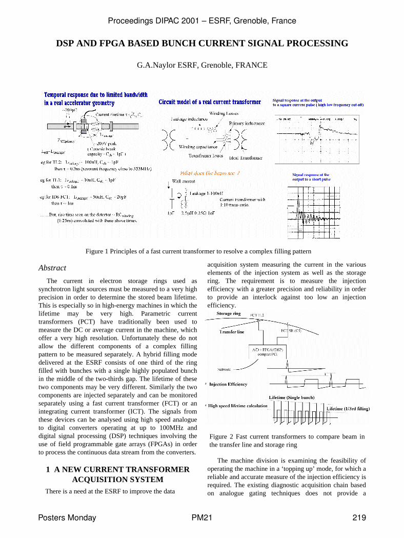
Figure 1 Principles of a fast current transformer to resolve a complex filling pattern
Abstract
The current in electron storage rings used as synchrotron light sources must be measured to a very high precision in order to determine the stored beam lifetime. This is especially so in high-energy machines in which the lifetime may be very high. Parametric current transformers (PCT) have traditionally been used to measure the DC or average current in the machine, which offer a very high resolution. Unfortunately these do not allow the different components of a complex filling pattern to be measured separately. A hybrid filling mode delivered at the ESRF consists of one third of the ring filled with bunches with a single highly populated bunch in the middle of the two-thirds gap. The lifetime of these two components may be very different. Similarly the two components are injected separately and can be monitored separately using a fast current transformer (FCT) or an integrating current transformer (ICT). The signals from these devices can be analysed using high speed analogue to digital converters operating at up to 100MHz and digital signal processing (DSP) techniques involving the use of field programmable gate arrays (FPGAs) in order to process the continuous data stream from the converters.
1 A NEW CURRENT TRANSFORMER ACQUISITION SYSTEM
There is a need at the ESRF to improve the data
acquisition system measuring the current in the various elements of the injection system as well as the storage ring. The requirement is to measure the injection efficiency with a greater precision and reliability in order to provide an interlock against too low an injection efficiency.
Figure 2 Fast current transformers to compare beam in the transfer line and storage ring
The machine division is examining the feasibility of operating the machine in a ‘topping up’ mode, for which a reliable and accurate measure of the injection efficiency is required. The existing diagnostic acquisition chain based on analogue gating techniques does not provide a
Proceedings DIPAC 2001 – ESRF, Grenoble, France
Posters Monday PM21 219
sufficiently reliable measurement when different filling patterns may be injected giving different pulse shape responses due to the limited band-pass of the current transformers (fig 1). Recent advances in high-speed digital acquisition and processing techniques allow the measurement to be performed digitally and with a much greater precision. The limited frequency response of the current transformers can be compensated in the time domain using correlation (fig 2,3). The measured pulse is numerically cross-correlated with a waveform of the anticipated pulse shape. The cross-correlation gives then a measure of the total injected charge and is fairly immune to noise that may be present on the signal. The measurement is immune both to high frequency noise and low frequency noise (the latter which gives rise to uncertainty in the base-line offset. The much greater precision afforded by such techniques will also allow the lifetime to be determined more quickly. This is important in the optimisation of machine parameters.
2 CALCULATION OF THE CROSSCORRELATION
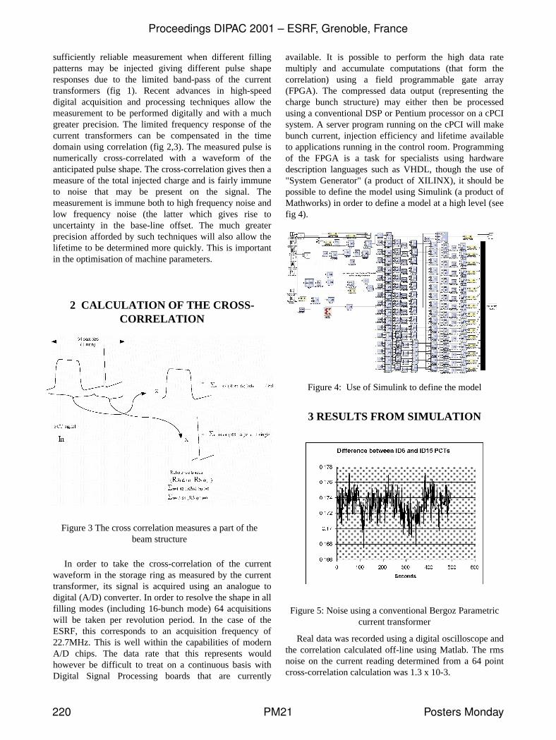
Figure 3 The cross correlation measures a part of the beam structure
In order to take the cross-correlation of the current waveform in the storage ring as measured by the current transformer, its signal is acquired using an analogue to digital (A/D) converter. In order to resolve the shape in all filling modes (including 16-bunch mode) 64 acquisitions will be taken per revolution period. In the case of the ESRF, this corresponds to an acquisition frequency of 22.7MHz. This is well within the capabilities of modern A/D chips. The data rate that this represents would however be difficult to treat on a continuous basis with Digital Signal Processing boards that are currently
available. It is possible to perform the high data rate multiply and accumulate computations (that form the correlation) using a field programmable gate array (FPGA). The compressed data output (representing the charge bunch structure) may either then be processed using a conventional DSP or Pentium processor on a cPCI system. A server program running on the cPCI will make bunch current, injection efficiency and lifetime available to applications running in the control room. Programming of the FPGA is a task for specialists using hardware description languages such as VHDL, though the use of "System Generator" (a product of XILINX), it should be possible to define the model using Simulink (a product of Mathworks) in order to define a model at a high level (see fig 4).
Figure 4: Use of Simulink to define the model
3 RESULTS FROM SIMULATION
Figure 5: Noise using a conventional Bergoz Parametric current transformer
Real data was recorded using a digital oscilloscope and the correlation calculated off-line using Matlab. The rms noise on the current reading determined from a 64 point cross-correlation calculation was 1.3 x 10⁻³.
Proceedings DIPAC 2001 – ESRF, Grenoble, France
220 PM21 Posters Monday
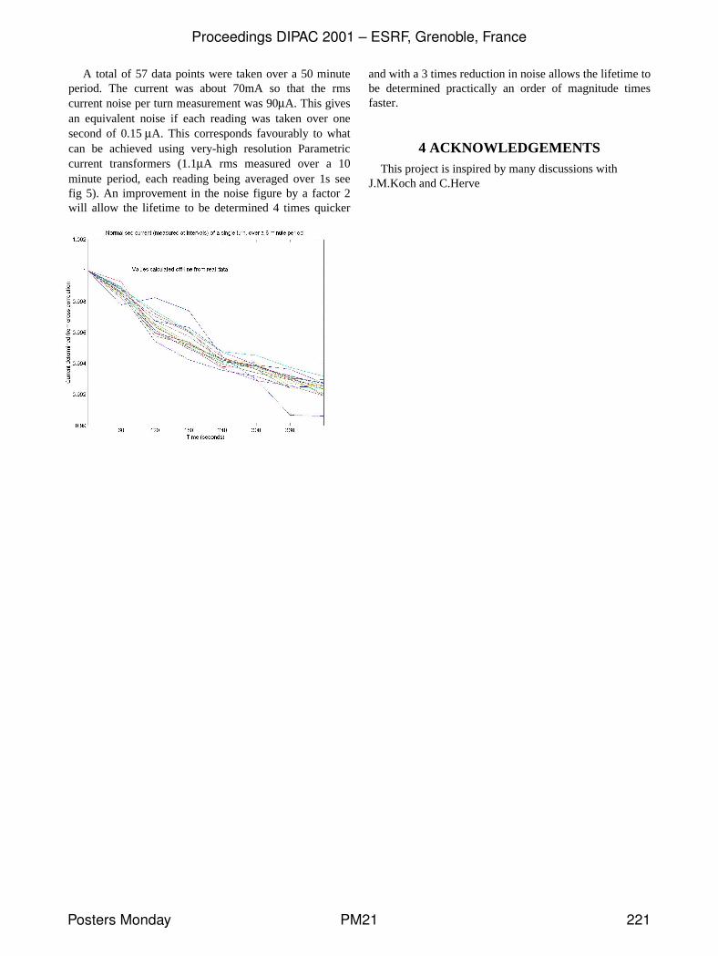
A total of 57 data points were taken over a 50 minute period. The current was about 70mA so that the rms current noise per turn measurement was 90µA. This gives an equivalent noise if each reading was taken over one second of 0.15 µA. This corresponds favourably to what can be achieved using very-high resolution Parametric current transformers (1.1µA rms measured over a 10 minute period, each reading being averaged over 1s see fig 5). An improvement in the noise figure by a factor 2 will allow the lifetime to be determined 4 times quicker
and with a 3 times reduction in noise allows the lifetime to be determined practically an order of magnitude times faster.
4 ACKNOWLEDGEMENTS This project is inspired by many discussions with
J.M.Koch and C.Herve
Proceedings DIPAC 2001 – ESRF, Grenoble, France
Posters Monday PM21 221