temporary traffic control devices the exception of trailer mounted devices described below,...
TRANSCRIPT

Gen
eral
Pr
ovis
ions
6K-r
Field Manual January 2018
Temporary Traffic Control Devices
Crashworthy Testing ComplianceWith the exception of Trailer Mounted Devices described below, Temporary Traffic Control devices, including Type A and Type B channelizing devices, Type III barricades, ballast systems, and sign support structures used on any roadway open to public travel, shall be crashworthy when installed facing traffic or turned away from traffic.FHWA policy requires that all roadside appurtenances, including Temporary Traffic Control devices, have been successfully crash tested in accordance with the National Cooperative Highway Research Program (NCHRP) Report 350, “Recommended Procedures for the Safety Performance Evaluation of Highway Features” or the American Association of State Highway and Transportation Officials (AASHTO) “Manual for Assessing Safety Hardware (MASH).”
Trailer Mounted DevicesWhen required, trailer mounted devices, such as Arrow Boards and Portable Changeable Message Signs shall be installed per Layout 7. When not in use, the devices should not be stored on the shoulder�
High Visibility ClothingAll workers who are exposed to traffic, work vehicles, or construction equipment within the TTC zone shall wear high-visibility safety apparel meeting ANSI/ISEA 107-2004 (or ANSI/ISEA 107-2010) Performance Class 2 or 3 requirements. ANSI/ISEA 107-2015 Type R, Performance Class 2 or 3 is also acceptable. Clothing shall have an attached original label indicating the Performance Class. When working in an area that does not require the use of a hard hat for head protection, a high visibility hat should be worn.
Flashing Warning LightsFlashing warning lights may be used to supplement road, ramp, and sidewalk closure signing, and other warning signs and/or barricades to attract the road user’s attention�
Vehicle Warning LightsAll vehicles shall have approved operating vehicle warning lights when decelerating to enter a TTC zone and again when a vehicle leaves the TTC zone and enters the traveled traffic lane. All vehicles within a mobile TTC operation or working within 15 feet of an open traffic lane should have approved vehicle warning lights. Vehicle warning lights shall be visible for 360 degrees around the vehicle at a minimum height of 3 1/2 feet and a radius of 60 feet or greater.

Gen
eral
Pr
ovis
ions
6K-s
Field Manual January 2018
Optional DevicesSome signs and devices on the TTC layouts are shown as optional or have factors that may make them optional. Some advance warning signs and/or channelizing devices may be omitted for low speed roads and/or if the duration will be less than 1 hour. Read the associated notes on each layout for options. The ONE LANE ROAD AHEAD sign is an example of a sign that is only required for higher speeds. The BE PREPARED TO STOP sign is shown as optional on most TTC layouts. This sign is usually added to the complement of signs when restricted sight distances warrant additional warning to the motorist or the advance warning area becomes extremely long due to sight distances or a move of the operation�
Channelizing DevicesThe function of channelizing devices is to delineate a desired vehicle path, mark specific hazards on or near the roadway, separate opposing traffic flows, and partially or totally close the roadway. See Figure 6K-7, Longitudinal Drop-off Guidelines (pages 6K-aj through 6K-al) for the use of channelizing devices adjacent to shoulder edge drop-offs or uneven lanes.Channelizing devices include cones, drums, barricades, temporary raised islands, and various kinds of markers. The devices are broken into two type classifications (Type A and Type B) based upon the nighttime visibility of the device. Visibility is determined based upon the total retroreflective area of the device. Devices with less than 270 square inches are classified as Type A channelizing devices and devices with more than 270 square inches of retroreflective area are Type B channelizing devices. Type A channelizing devices may be used in attended TTC zones and Type B channelizing devices shall be used if the TTC zone will be left unattended or be in place longer than 12 hours. Where a Type B channelizing device, such as a drum, causes an isolated sight restriction, or is too wide for a space, a 42-inch tall weighted channelizer may be substituted. This substitution may be used in unattended overnight conditions as approved by the road authority� When used, the spacing of the weighted channelizers should be reduced by up to 50 percent� Figure 6K-3 shows a breakdown of devices by Channelizer Type (drawn to approximate scale). See the MN MUTCD, Part 6F for additional details on application restrictions�

Gen
eral
Pr
ovis
ions
6K-t
Field Manual January 2018
Types of Channelizing DevicesFigure 6K-3
TYPE A CHANNELIZERS
42”minimum
WeightedChannelizer
36”minimum
18”minimum
SurfaceMounted
Delineator
TubularMarkers
daytimelow speed
only
Cones*
18”minimum
28” minimumto 36”
maximum
daytimelow speed
only
*Cones shall not be used in unattended work zones�
OpposingTraffic
Lane Divider
36”minimum
• Type A channelizing devices are typically used in attended Temporary Traffic Control zones�
TYPE C CHANNELIZER
Type III Barricade
60”minimum
48” minimum
• Orange diagonals shall slope down toward the traffic side�• Signs mounted on Type III barricades should not cover more than 50 percent of the top two rails or 33 percent of the total area of the three rails�• Type A Flashing Warning Lights may be used - place on the side with traffic�
TYPE B CHANNELIZERS
Type IBarricade
36”minimum
24” minimum
Type IIBarricade
36”minimum
24” minimum
Drum
36inches
minimum
Direction Indicator Barricade
24”
36”minimum
Vertical Panel
36”minimum
8”-12”
24”minimum
8”-12”
36”minimum
• Channelizers used on high speed roadways shall have a minimum of 270 square inches of retroreflective area facing road users�• Orange diagonals shall slope down toward the traffic side�• Type B channelizing devices shall be used if the Temporary Traffic Control zone will be installed for more than 12 hours or if it is left unattended� Weighted channelizers may be used in lieu of a Type B channelizer with the permission of the road authority�• Type A Flashing Warning Lights may be used - place on the side with traffic�

Gen
eral
Pr
ovis
ions
6K-u
Field Manual January 2018
Types of Channelizing DevicesFigure 6K-3
TYPE A CHANNELIZERS
42”minimum
WeightedChannelizer
36”minimum
18”minimum
SurfaceMounted
Delineator
TubularMarkers
daytimelow speed
only
Cones*
18”minimum
28” minimumto 36”
maximum
daytimelow speed
only
*Cones shall not be used in unattended work zones�
OpposingTraffic
Lane Divider
36”minimum
• Type A channelizing devices are typically used in attended Temporary Traffic Control zones�
TYPE C CHANNELIZER
Type III Barricade
60”minimum
48” minimum
• Orange diagonals shall slope down toward the traffic side�• Signs mounted on Type III barricades should not cover more than 50 percent of the top two rails or 33 percent of the total area of the three rails�• Type A Flashing Warning Lights may be used - place on the side with traffic�
TYPE B CHANNELIZERS
Type IBarricade
36”minimum
24” minimum
Type IIBarricade
36”minimum
24” minimum
Drum
36inches
minimum
Direction Indicator Barricade
24”
36”minimum
Vertical Panel
36”minimum
8”-12”
24”minimum
8”-12”
36”minimum
• Channelizers used on high speed roadways shall have a minimum of 270 square inches of retroreflective area facing road users�• Orange diagonals shall slope down toward the traffic side�• Type B channelizing devices shall be used if the Temporary Traffic Control zone will be installed for more than 12 hours or if it is left unattended� Weighted channelizers may be used in lieu of a Type B channelizer with the permission of the road authority�• Type A Flashing Warning Lights may be used - place on the side with traffic�
Work Zone SigningAs a general rule, signs should be located on the right-hand side of a two-way roadway and on both the right and left sides of a multi-lane divided roadway. See Figure 6K-11, TTC Distance Charts (page 6K-ap or back cover) for the Advance Warning Sign Spacing distance (A). When special emphasis is needed, signs may be placed on both the left and right sides of a two-way roadway. Signs, although ordinarily mounted on posts for long term operations, may be mounted on or above barricades or on temporary supports�Signs mounted on temporary supports should not be placed in the open traveled lane where they pose a hazard to traffic nor where pedestrians are expected to travel. Generally, these signs are placed on the shoulder or in the parking lane of the street or highway. The signs should not be blocked from view by parked vehicles, trees, or other sight obstructions on or near the roadway. Any portable sign or barricade placed in a pedestrian walkway that could be a hazard to a visually impaired pedestrian should have a detectable edge to guide the pedestrian around the hazard�Signs shall not be mounted on existing traffic signs, posts, or other utility structures without permission from the proper authority. All signs shall be mounted so that the sign face is approximately perpendicular to the roadway and vertically plumb in accordance with Quality Standards (pages 6K-93 through 6K-108). The bottom of signs mounted on barricades or temporary supports shall be no less than 1 foot above the traveled way. All regulatory signs on portable supports shall be mounted with a minimum mounting height of 4 feet measured from the ground to the center of the sign face� Supplemental advisory plaques shall be placed directly below or on the lower side of the warning sign nearest traffic.Some activity areas move slowly down a roadway and away from the operation’s advance signing. The distance from the last advance warning sign to the activity area should not allow the motorist to forget the existence of the Temporary Traffic Control zone. For high-speed streets and rural highways, the maximum distance from the last sign to a point where the driver detects the activity area shall not exceed 1 mile. In urban areas, the number of intersections shall be considered and this distance reduced accordingly�All advance warning signs shall be at least 48 x 48 inches in size when used on high speed roadways. Warning signs used on low speed roadways shall be at least 36 x 36 inches in size. Smaller signs may be used as approved by the road authority where larger signs become an additional hazard to motorists and pedestrians�Advance warning signs should be installed for drivers entering the TTC zone from cross streets. ROAD WORK AHEAD signs on intersecting roadways shall be installed if the motorist will not encounter another advance warning sign prior to reaching the activity area except for mobile operations.All signs used at night shall be retroreflective with a material that has a smooth sealed outer surface that shows the same shape and color both day and night. Non-retroreflective mesh signs shall not be used at any time. Retroreflectorized

Gen
eral
Pr
ovis
ions
6K-v
Field Manual January 2018
roll-up signs may be used for daytime and for nighttime only when workers are present to monitor the signs�On multi-lane divided roadways, where the median shoulder is narrow (less than 6 feet), the 48 x 48 inch advance warning signs, as shown on the TTC layouts, may not fit on the left side of the roadway. Where this situation occurs, one of the following options may be used:
1� Reduce the left side signs sizes, or
2� Eliminate the left side signing, use an additional RIGHT LANE CLOSED (or LEFT as appropriate) sign on the right side, and require the use of an arrow board on the shoulder at the beginning of the lane closure taper�
All advance warning signs shall be removed, covered, or turned to face away from traffic when they are no longer required or appropriate.

Gen
eral
Pr
ovis
ions
6K-w
Field Manual January 2018
Sign Codes Quick ReferenceFigure 6K-4
For additional signs and information on typical sizes and usage, see the Minnesota Manual on Uniform Traffic Control Devices�
R1-X3P
R3-1No Right Turn
R1-1
R1-2
R2-1
R2-6bP
R3-2No Left Turn
R9-10
R11-2
R10-6(R or L)
R9-11(R or L)
R11-4
W1-4 (R or L)Reverse Curve
W1-6One DirectionLarge Arrow(R or L)
W3-1Stop Ahead
W3-2Yield Ahead
W3-3Signal Ahead
W3-4
W3-5Speed Reduction
W4-2 (R or L)Lane Ends
W7-3aP
W6-4Opposing TrafficLane Divider
W8-1
W8-1a
W8-8
W8-9
W8-11
W8-2
W8-7
EN DWO R KZO N ES P E EDL I M I T
R2-12
W8-15
W5-1
R4-7cKeep Right
R3-18U-Turn & LeftTurn Prohibition
R3-7
R4-11Bikes may usefull lane
R3-5(R or L)
R9-9

Gen
eral
Pr
ovis
ions
6K-x
Field Manual January 2018
W20-1
W20-1a
W20-4
W20-7Flagger Ahead
W20-X3(R or L)
W20-X12
W20-X13(R or L)
W20-X16
W20-X18
W13-4P
W14-1
W14-X12
W14-2 W20-X10
W20-X11Reduced Width
W20-5
W12-1Double Arrow
W20-X17
W14-X13
W20-3
W21-X6
W8-15PMotorcyclePlaque
W8-23
W8-24
W20-X21
W20-X20
W21-X5
W21-X5a
W21-1aWorker Ahead
W20-X19
W21-X3Large Arrow(Variable Arrow Angle)
W21-X4a
W16-7P(R or L)
W13-1P
W16-3PDistance Plaque
W16-2PDistance Plaque
Sign Codes Quick ReferenceFigure 6K-4
For additional signs and information on typical sizes and usage, see the Minnesota Manual on Uniform Traffic Control Devices�

Gen
eral
Pr
ovis
ions
6K-y
Field Manual January 2018
For additional signs and information on typical sizes and usage, see the Minnesota Manual on Uniform Traffic Control Devices�
G20-X10
G20-X11P
G20-X9(VariableArrow Angle)
G20-X7(VariableArrow Angle)
W21-X10
W21-X11(R or L)
W21-X12
W24-1Double ReverseCurve(R or L)
G20-X1
G20-4
G20-5aP
W21-X7Flagger Panel
W21-X9
G20-X12P
G20-X14
G20-X17
D9-6HandicappedAccessible
G20-X15
G20-X18
G20-X18P
Sign Codes Quick ReferenceFigure 6K-4

Gen
eral
Pr
ovis
ions
6K-z
Field Manual January 2018
Typical TPAR DevicesFigure 6K-5
32 inchminimum
2 inch maximum
Pedestrian Channelizerusing a Temporary Barrier
Detectable Edge
⑤
②③
Handrailing Edge
Detectable Edge
2 inch maximum
34 - 38 inch
Pedestrian Channelizer
②
⑥
③①
⑧
Detectable Edgefor Portable Sign Stand
②③
Sidewalk Barricade
Typical audiblemessage device
location when used�
34 inchminimum2 inch
maximumWalkwaySurface
①③②
⑩
⑪
NOTES:① ① To prevent any tripping hazard to pedestrians, ballast shall be located behind or
internal to the device. Any support on the front of the device shall not extend into the 48 inch minimum walkway clear space and shall have 0.5 inch maximum height above the walkway surface with approved beveling (see Note #9 on page 6K-aa for beveling details).
① ② Detectable edges for long canes shall be continuous and 6 inches minimum above the walkway surface and have color or markings contrasting with the walkway surface. The detectable edge around a portable sign stand should be placed in the walkway area in which the sign poses a hazard to a visually impaired pedestrian.
① ③ Devices shall not block water drainage from the walkway. A gap height or opening from the walkway surface up to 2 inch maximum height is allowed for drainage purposes.
4. Railings or other objects may protrude a maximum of 4 inches into the walkway clear space when located 27 inches minimum above the walkway surface.
① ⑤ Longitudinal channelizing devices for pedestrians shall be 32 inches high or greater.
① ⑥ When hand guidance is required, the top rail or top surface shall be:• In vertical plane perpendicular to the walkway above the detectable edge,• Continuous at a height of 34 to 38 inches above the walkway surface, and• Supported with minimal interference to the pedestrian’s hands or fingers.
7. All devices shall be free of sharp or rough edges and fasteners (bolts) shall be rounded to prevent harm to hands, arms, or clothing.
① ⑧ All devices used to channelize pedestrian flow should interlock such that gaps do not allow pedestrians to stray from the channelized path.
9. Any pedestrian devices used to provide positive protection (traffic or hazard) for pedestrians or workers shall meet crashworthy requirements appropriate for the barriers’ application.
① ⑩ Barricades shall be used to close the entire width of the walkway surface.① ⑪ A walkway surface shall be firm, stable, and slip resistant. Refer to the MnDOT website Pedestrian Accommodations Through Work Zones for more information (http://www.dot.state.mn.us/trafficeng/workzone/apr.html).
Gen
eral
Pr
ovis
ions
6K-aa
Field Manual January 2018
Typical TPAR DevicesFigure 6K-5
Typical TPAR DevicesFigure 6K-5
Shown withProtective Edge
Shown withSide Apron
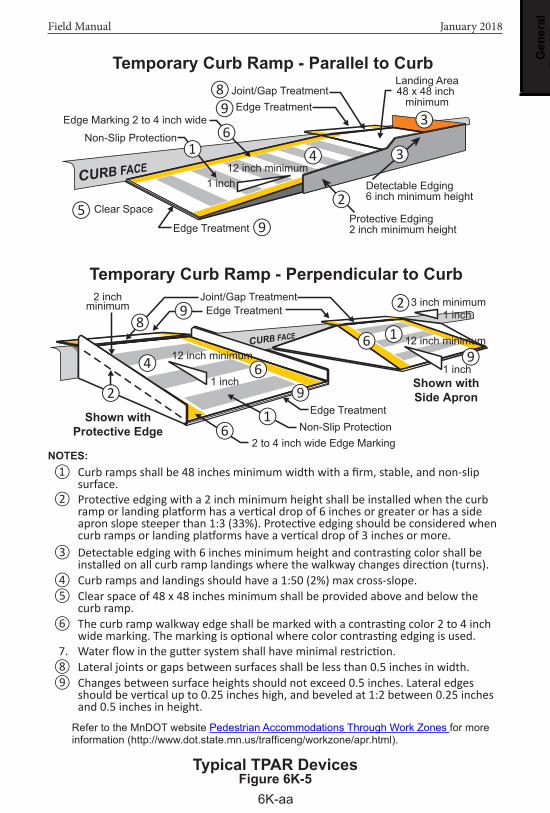
Temporary Curb Ramp - Parallel to Curb
Edge Marking 2 to 4 inch wide
Non-Slip Protection
Clear Space
Edge TreatmentProtective Edging2 inch minimum height
Detectable Edging6 inch minimum height
Landing Area48 x 48 inch
minimumJoint/Gap TreatmentEdge Treatment
12 inch minimum1 inch
Temporary Curb Ramp - Perpendicular to Curb
2 to 4 inch wide Edge MarkingNon-Slip Protection
Edge Treatment
Joint/Gap TreatmentEdge Treatment
3 inch minimum2 inchminimum
④
⑤
①
⑨
⑧
⑥⑨
③
②
④
⑧⑨
⑥⑨
①
①
⑥
⑥
②
⑨
②
③
1 inch
12 inch minimum1 inch
12 inch minimum
1 inch
NOTES:① ① Curb ramps shall be 48 inches minimum width with a firm, stable, and non-slip
surface.① ② Protective edging with a 2 inch minimum height shall be installed when the curb ramp or landing platform has a vertical drop of 6 inches or greater or has a side apron slope steeper than 1:3 (33%). Protective edging should be considered when curb ramps or landing platforms have a vertical drop of 3 inches or more.
① ③ Detectable edging with 6 inches minimum height and contrasting color shall be installed on all curb ramp landings where the walkway changes direction (turns).
① ④ Curb ramps and landings should have a 1:50 (2%) max cross-slope.① ⑤ Clear space of 48 x 48 inches minimum shall be provided above and below the
curb ramp.① ⑥ The curb ramp walkway edge shall be marked with a contrasting color 2 to 4 inch wide marking. The marking is optional where color contrasting edging is used.
7. Water flow in the gutter system shall have minimal restriction.① ⑧ Lateral joints or gaps between surfaces shall be less than 0.5 inches in width.① ⑨ Changes between surface heights should not exceed 0.5 inches. Lateral edges should be vertical up to 0.25 inches high, and beveled at 1:2 between 0.25 inches and 0.5 inches in height.
Refer to the MnDOT website Pedestrian Accommodations Through Work Zones for more information (http://www.dot.state.mn.us/trafficeng/workzone/apr.html).

Gen
eral
Pr
ovis
ions
6K-ab
Field Manual January 2018
Portable Changeable Message Signs (PCMS)The primary purpose of Portable Changeable Message Signs (PCMS) is to advise the driver of unexpected traffic and routing situations.
General Guidelines• A PCMS should be used to supplement conventional signs, pavement
markings, and lighting.
• If a PCMS is used as an arrow board, it shall meet all of the requirements of an arrow panel, and shall be used solely as an arrow board�
• Performance specifications can be found in the current version of the Minnesota Manual on Uniform Traffic Control Devices (MN MUTCD), Part 6, Section 6F.
• A PCMS installed on the shoulder of a road shall be accompanied with Type B channelizing devices (see Layout 7).
Messages• Each display should contain a single thought� The message should
consist of no more than 2 displays on high speed roadways and no more than 3 displays on low speed roadways.
• The entire message should be readable twice at the posted speed limit. See Table 6K-2 (page 6K-ac) for additional requirements.
• An accurate description of the work location or the incident location is critical�
• The PCMS shall have readable up-to-date information. Any delay message should accurately reflect the traffic delay time.
• The PCMS message shall use days of the week not calendar dates unless the PCMS is placed 7 days or greater in advance.
• The use of abbreviations is discouraged. The entire word should be spelled out whenever space permits.
• If abbreviations are used, they should be easily understood (see Table 6K-3: Abbreviations Allowable on PCMS(s), pages 6K-ad through 6K-ag and Table 6K-4: Unacceptable PCMS Abbreviations, page 6K-ah).
• Displays shall not scroll horizontally or vertically across the face of the sign�
• If multiple PCMSs are used, make sure the messages do not conflict.
For more information on the use of PCMSs, see the CMS Manual of Practice at: http://dotapp7.dot.state.mn.us/projectPages/pages/projectDetails.jsf;jsessionid=t3PoW79ooteIQ8QF9YwBytyc.9773acc1-da1d-30bb-b6a7-70c38c81c330?id=4590&type=CONTRACT.

Gen
eral
Pr
ovis
ions
6K-ac
Field Manual January 2018
RequirementsSpecifications for use of a PCMS are in the following table.
Table 6K-2: Specifications for use of a PCMS
Requirements Type A Type B Type C
Line(s) of Message 1 Line 2 Lines 3 Lines
Typical Mounting Vehicle Mounted Vehicle or Trailer Mounted Trailer Mounted
Allowed UsageEmergency and Incident Management
Advance Warning Advance Warning and Advance Notice
Legibility Distance Requirements Legible at 350 feet Legible at 750 feet Legible at 900 feet
Minimum Character Height 10 inches ≤ 40 mph* = 14 inches
≥ 45 mph* = 18 inches18 inches
Maximum Number of Displays 1 ≤ 40 mph* = 3
≥ 45 mph* = 2≤ 40 mph* = 3≥ 45 mph* = 2
Message Cycle Constant At least 2 seconds per display
At least 2 seconds per display
Minimum Sign Height to Bottom of
Sign Panel
5 feet (rural)7 feet (urban)
5 feet (rural)7 feet (urban)
5 feet (rural)7 feet (urban)
Minimum PCMS Spacing 500 feet 1000 feet 1000 feet
* Posted speed limit prior to work starting�
The width-to-height ratio of the sign characters should be between 0.7 and 1.0. The stroke width-to-height ratio should be 0.2.
Gen
eral
Pr
ovis
ions
6K-ad
Field Manual January 2018
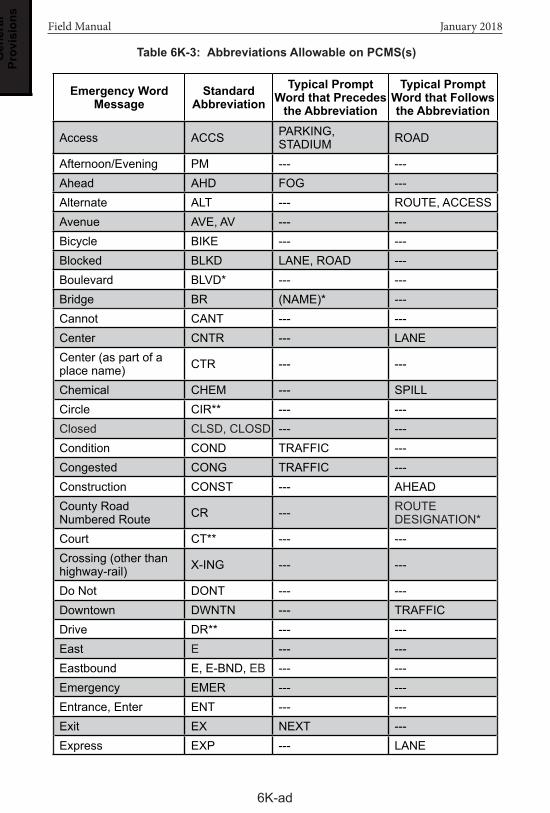
Table 6K-3: Abbreviations Allowable on PCMS(s)
Emergency Word Message
Standard Abbreviation
Typical Prompt Word that Precedes
the Abbreviation
Typical Prompt Word that Follows the Abbreviation
Access ACCS PARKING, STADIUM ROAD
Afternoon/Evening PM --- ---Ahead AHD FOG ---Alternate ALT --- ROUTE, ACCESSAvenue AVE, AV --- ---Bicycle BIKE --- ---Blocked BLKD LANE, ROAD ---Boulevard BLVD* --- ---Bridge BR (NAME)* ---Cannot CANT --- ---Center CNTR --- LANECenter (as part of a place name) CTR --- ---
Chemical CHEM --- SPILLCircle CIR** --- ---Closed CLSD, CLOSD --- ---Condition COND TRAFFIC ---Congested CONG TRAFFIC ---Construction CONST --- AHEADCounty Road Numbered Route CR --- ROUTE
DESIGNATION*Court CT** --- ---Crossing (other than highway-rail) X-ING --- ---
Do Not DONT --- ---Downtown DWNTN --- TRAFFICDrive DR** --- ---East E --- ---Eastbound E, E-BND, EB --- ---Emergency EMER --- ---Entrance, Enter ENT --- ---Exit EX NEXT ---Express EXP --- LANE

Gen
eral
Pr
ovis
ions
6K-ae
Field Manual January 2018
Emergency Word Message
Standard Abbreviation
Typical Prompt Word that Precedes
the Abbreviation
Typical Prompt Word that Follows the Abbreviation
Expressway EXPRS, EXPWY** --- ---
Feet FT --- ---
Freeway FRWY, FWY** --- ---
Friday FRI --- ---Frontage FRNTG --- ROADHazardous HAZ --- DRIVINGHazardous Material HAZMAT --- ---High Occupancy Vehicle HOV --- ---
Highway HWY --- ---Highway-Rail Grade Crossing RR XING --- ---
Hospital HOSP --- ---Hour(s) HR, HRS --- ---Information INFO --- ---International INTL --- ---Interstate Numbered Route I --- ROUTE
DESIGNATION*Junction/Intersection JCT --- ---
Lane LN, LA RIGHT, LEFT, CENTER ---
Left LFT, LF, L --- ---Local LOC --- TRAFFICLower LWR --- LEVELMaintenance MAINT --- ---Major MAJ --- CRASHMaximum MAX --- ---Mile(s) MIL --- ---Miles Per Hour MPH --- ---Minnesota Numbered Route MN ROUTE
DESIGNATION*Minimum MIN --- ---Minor MNR --- CRASH
Table 6K-3: Abbreviations Allowable on PCMS(s), cont.

Gen
eral
Pr
ovis
ions
6K-af
Field Manual January 2018
Emergency Word Message
Standard Abbreviation
Typical Prompt Word that Precedes
the Abbreviation
Typical Prompt Word that Follows the Abbreviation
Minute(s) MIN --- ---Monday MON --- ---Morning/Late Night AM --- ---Mount MT --- ---Mountain MTN --- ---National NATL --- ---Normal NORM --- ---North N --- ---Northbound N, N-BND, NB --- ---Oversized OVRSZ --- LOADParking PKING --- ---Parkway PKWY** --- ---Pavement PVMT WET, GROOVED ENDSPedestrian PED --- ---Place PL** --- ---Pounds LBS --- ---Prepare PREP --- TO STOPRight RT, R KEEP, NEXT ---Road RD** --- ---
Roadwork RDWK --- AHEAD (DISTANCE)
Route RT, RTE BEST, ALTERNATE ---Saint ST --- ---Saturday SAT --- ---Service SERV --- ---Shoulder SHLDR --- ---Signal SIGNL --- OUTSlippery SLIP --- ---South S --- ---Southbound S, S-BND, SB --- ---Speed SPD --- ---
Stadium STDM NAME OF STADIUM
PARKING, NEXT EXIT
Table 6K-3: Abbreviations Allowable on PCMS(s), cont.

Gen
eral
Pr
ovis
ions
6K-ag
Field Manual January 2018
Emergency Word Message
Standard Abbreviation
Typical Prompt Word that Precedes
the Abbreviation
Typical Prompt Word that Follows the Abbreviation
Street ST** --- ---Sunday SUN --- ---Sweeper SWEEP --- AHEADTemporary TEMP --- ---Terrace TER** --- ---Thursday THUR --- ---Tons of Weight T --- ---Traffic TRAF --- ---Trail TR** --- ---Tuesday TUE --- ---Two-Way Intersection 2-WAY --- ---
Two-Wheeled Vehicles CYCLES --- ---
Upper UPR --- LEVEL
US Numbered Route US --- ROUTE DESIGNATION*
Vehicle(s) VEH, VEHS --- ---Warning WARN --- ---Wednesday WED --- ---West W --- ---Westbound W, W-BND,WB --- ---Will Not WONT --- ---
NOTES:* A space and no dash shall be placed between the abbreviation and the number of the route�
** This abbreviation shall not be used for any application other than the name of a roadway.
Table 6K-3: Abbreviations Allowable on PCMS(s), cont.

Gen
eral
Pr
ovis
ions
6K-ah
Field Manual January 2018
Abbreviation Intended Word Common Misinterpretation
ACC Accident Access (Road)CLRS Clears ColorsDLY Delay DailyFDR Feeder FederalL Left Lane (Merge)LT Light (Traffic) LeftPARK Parking ParkPOLL Pollution (Index) PollRED Reduce RedSTAD Stadium StandardTH Trunk Highway Misunderstood
Table 6K-4: Unacceptable PCMS Abbreviations

Gen
eral
Pr
ovis
ions
6K-ai
Field Manual January 2018
Advance Warning Arrow Board SpecificationFigure 6K-6
Operating ModePanel Display
(Element layout for Type C panel shown�)
1. At least one of the following threemodes shall be provided:
Flashing Arrow
Sequential Chevron
Sequential Arrow
3. At least one of the following three modes shall be provided:
Arrow StickArrow Sticks may supplement other TTC devices, but shall not be used in place of arrow boards�
Caution
Flashing Four Corners
Flashing Bar
Alternating Flashing Diamonds
(Right arrow is shown, left arrow is similar)
2. The following mode shall be provided:
Flashing Double ArrowMove/Merge Right or Left
Move/Merge Right
Move/Merge Right
Move/Merge Right
PanelType
MinimumSize
(Inches)
Minimum LegibilityDistance(miles)
MinimumNumber ofElements
RecommendedUsage
A 48 x 24 0�50 12 Low Speed Streets
B 60 x 30 0�75 13Anything not covered
in A or C
C 96 x 48 1�00 15Freeways andExpressways