tender document supply , erection & commissioning of … · tender no. ms/piping/ibr/advt. no....
TRANSCRIPT

SECURITY PAPER MILL, HOSHANGABAD-461005(M.P.)(A unit of Security Printing & Minting Corporation of India Ltd.)
Wholly owned by Government of India
TENDER DOCUMENT
SUPPLY , ERECTION & COMMISSIONINGOF PIPES/PIPE FITTINGS/VALVES
AS PER INDIAN BOILER REGULATIONS(IBR)ON TURNKEY BASIS
Not TransferableSecurity Classification: Non-Security Item
TENDER DOCUMENT FOR SUPPLY, ERECTION & COMMISSIONING of PIPES/PIPEFITTINGS/VALVES (IBR) ON TURNKEY BASIS
Tender No. MS/PIPING/IBR/Advt. No. 92/2221 Dated: 16.11.2012
This Tender Document Contains 129 + 2 (Drawings) + 2 (Make List) Pages.
Tender Documents is sold to:
M/s
Address
Details of Contact person in SPM regarding this tender:
Name, Designation : Shri. Rajkumar ROfficer Materials
Address : Security Paper MillHoshangabadM.P-461005
Phone : 07574-279847, 07574-279791
Fax : 07574-255170
Email : [email protected][email protected]
1
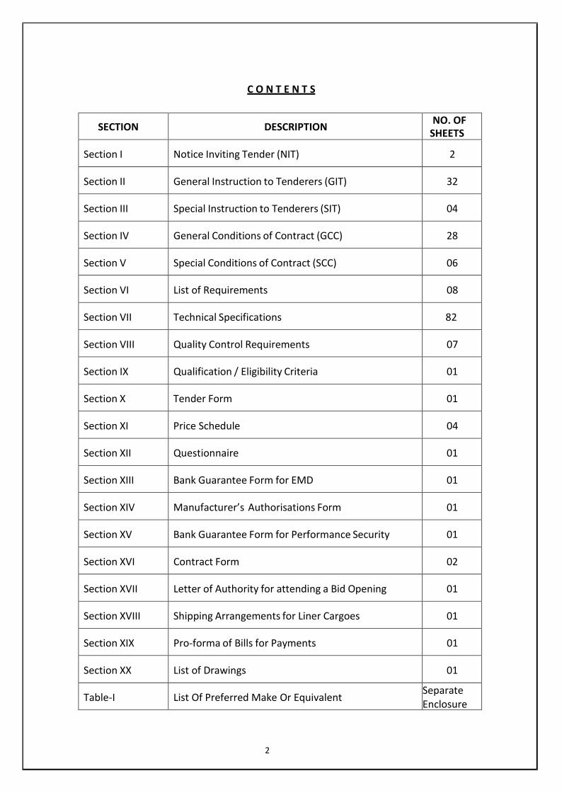
C O N T E N T S
SECTION DESCRIPTION NO. OFSHEETS
Section I Notice Inviting Tender (NIT) 2
Section II General Instruction to Tenderers (GIT) 32
Section III Special Instruction to Tenderers (SIT) 04
Section IV General Conditions of Contract (GCC) 28
Section V Special Conditions of Contract (SCC) 06
Section VI List of Requirements 08
Section VII Technical Specifications 82
Section VIII Quality Control Requirements 07
Section IX Qualification / Eligibility Criteria 01
Section X Tender Form 01
Section XI Price Schedule 04
Section XII Questionnaire 01
Section XIII Bank Guarantee Form for EMD 01
Section XIV Manufacturer’s Authorisations Form 01
Section XV Bank Guarantee Form for Performance Security 01
Section XVI Contract Form 02
Section XVII Letter of Authority for attending a Bid Opening 01
Section XVIII Shipping Arrangements for Liner Cargoes 01
Section XIX Pro-forma of Bills for Payments 01
Section XX List of Drawings 01
Table-I List Of Preferred Make Or Equivalent SeparateEnclosure
2

NOTICE INVITING TENDER (NIT)(Section – I)
Tender No. MS/PIPING/IBR/Advt. No. 92/2221 Dated:16.11.2012
1. Sealed tenders are invited from eligible and qualified tenderers for supply of following goods &Services:
ScheduleNo.
Brief Description of Goods/Services
Quantity(with unit)
Earnest Money(in Rs.)
1.Supply , Erection & Commissioning on turnkey basis ofPipes/Pipe Fittings/Valves (IBR)as per List of Requirement (Section-VI) of this tender
As per List ofRequirements
(Section VI)
Rs. 1,70,000/‐(Rs. One LakhSeventy thousandonly)
Type Of Tender Single stage (three packet), National Competitive Bidding
Tender Cost Rs. 1000/‐ (Rs. One Thousand Only)Date and time of Pre‐bid conference 08.12.2012 at 11.00 AMPlace of Pre‐bid conference Security Paper Mill, HoshangabadClosing date and time for receipt of tenders Up to 10.30 Hrs till 08.01.2013Place of receipt of tenders Security Paper Mill, HoshangabadTime and date of opening of tenders 11.00 Hrs On 08.01.2013Place of opening of tenders Security Paper Mill, HoshangabadNominated Person/ Designation for receivebulky tenders
Officer – Materials
2. Interested tenderers may obtain further information about this requirement from the Purchase section,Security Paper Mill, Hoshangabad. They may also visit our website mentioned above for further details.
3. Tender documents may be purchased on payment of non‐refundable fee of Rs.1000/‐ per set in theform of account payee demand draft/ cashier’s cheque/ certified cheque, drawn on a scheduledcommercial bank in India, in favour of Security Paper Mill payable at Hoshangabad.
4. If requested, the tender documents will be mailed by registered post/speed post to the domesticTenderers, for which extra expenditure per set will be Rs. 100/‐ (Rupees Hundred) for domestic post.The tenderer is to add the applicable postage cost in the non‐refundable fee mentioned in para 3 above.
3
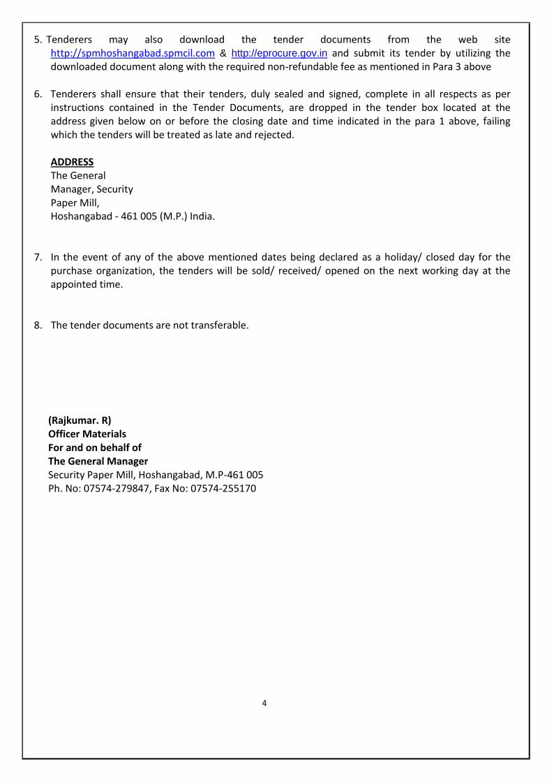
5. Tenderers may also download the tender documents from the web sitehttp://spmhoshangabad.spmcil.com & http://eprocure.gov.in and submit its tender by utilizing thedownloaded document along with the required non‐refundable fee as mentioned in Para 3 above
6. Tenderers shall ensure that their tenders, duly sealed and signed, complete in all respects as perinstructions contained in the Tender Documents, are dropped in the tender box located at theaddress given below on or before the closing date and time indicated in the para 1 above, failingwhich the tenders will be treated as late and rejected.
ADDRESSThe GeneralManager, SecurityPaper Mill,Hoshangabad ‐ 461 005 (M.P.) India.
7. In the event of any of the above mentioned dates being declared as a holiday/ closed day for thepurchase organization, the tenders will be sold/ received/ opened on the next working day at theappointed time.
8. The tender documents are not transferable.
(Rajkumar. R)Officer MaterialsFor and on behalf ofThe General ManagerSecurity Paper Mill, Hoshangabad, M.P-461 005Ph. No: 07574-279847, Fax No: 07574-255170
4

(Section – II)
GENERAL INSTRUCTIONS TO TENDERERS (GIT)
Kindly refer http://spmhoshangabad.spmcil.com/spmcil/uploaddocument/GIT.pdf for further details.
(GIT contains 32 Pages)
5

(Section – III)
SPECIAL INSTRUCTION TO TENDERER
The following Special Instructions to Tenderers will apply for this purchase. These special instructions willmodify/ substitute/ supplement the corresponding General Instructions to Tenderers (GIT)incorporated in Section II. The corresponding GIT clause numbers have also been indicated in thetext below. In case of any conflict between the provision in the GIT and that in the SIT, theprovision contained in the SIT shall prevail.
Sl. No. GIT ClauseNo.
Topic SITProvision
1. 8 Pre Bid Conference 1.2. 18 Earnest Money Deposit (EMD) 2.3. 19 Tender validity 3.4. 21 Submission of Tenders 4.5. 43 Parallel Contracts 5.6. 33 Evaluation Criteria for L1 Bidder 6.7. 21.1, 24.1 Corrections in GIT Clauses 7.8. Coordination with Statuary Bodies & outside
Agencies8.
1. PRE-BID CONFERENCE
Pre-bid conference will be held on 08.12.2012 at 11 AM held for this tender at SPM Hoshangabad.Bidder should send their queries if any before one week of pre-bid conference.
2. EARNEST MONEY DEPOSIT (EMD)
Tender should be accompanied with Earnest Money Deposit (Non-interest bearing) ofRs. 1,70,000/- (Rs. One Lakh Seventy thousand only) in the forms as given below.
a) Account Payee Demand Draft orb) Fixed Deposit Receipt orc) Banker’s cheque
The demand draft, fixed deposit receipt or banker’s cheque shall be drawn on anyscheduled commercial bank in India, in favour of Account specified in the Clause 3 of NIT. Theearnest money shall be valid for a period of forty five days beyond the validity period of thetender.
3. TENDER VALIDITY
3.1 The tender shall remain valid for acceptance for a period of 165 days after the date oftender opening prescribed in the tender document. Any tender valid for a shorter period shall betreated as unresponsive & rejected.
6
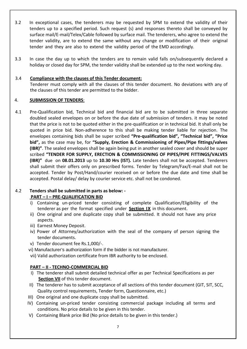
3.2 In exceptional cases, the tenderers may be requested by SPM to extend the validity of theirtenders up to a specified period. Such request (s) and responses thereto shall be conveyed bysurface mail/E-mail/Telex/Cable followed by surface mail. The tenderers, who agree to extend thetender validity, are to extend the same without any change or modification of their originaltender and they are also to extend the validity period of the EMD accordingly.
3.3 In case the day up to which the tenders are to remain valid falls on/subsequently declared aholiday or closed day for SPM, the tender validity shall be extended up to the next working day.
3.4 Compliance with the clauses of this Tender document:Tenderer must comply with all the clauses of this tender document. No deviations with any ofthe clauses of this tender are permitted to the bidder.
4. SUBMISSION OF TENDERS:
4.1 Pre-Qualification bid, Technical bid and financial bid are to be submitted in three separatedoubled sealed envelopes on or before the due date of submission of tenders. it may be notedthat the price is not to be quoted either in the pre-qualification or in technical bid. It shall only bequoted in price bid. Non-adherence to this shall be making tender liable for rejection. Theenvelopes containing bids shall be super scribed “Pre-qualification bid”, “Technical bid”, “Pricebid”, as the case may be, for “Supply, Erection & Commissioning of Pipes/Pipe fittings/valves(IBR)”. The sealed envelopes shall be again being put in another sealed cover and should be superscribed “TENDER FOR SUPPLY, ERECTION & COMMISSIONING OF PIPES/PIPE FITTINGS/VALVES(IBR)” due on 08.01.2013 up to 10.30 Hrs (IST). Late tenders shall not be accepted. Tenderersshall submit their offers only on prescribed forms. Tender by Telegram/Fax/E-mail shall not beaccepted. Tender by Post/Hand/courier received on or before the due date and time shall beaccepted. Postal delay/ delay by courier service etc. shall not be condoned.
4.2 Tenders shall be submitted in parts as below: -PART – I – PRE-QUALIFICATION BIDi) Containing un-priced tender consisting of complete Qualification/Eligibility of the
tenderer as per the format specified under Section IX in this document.ii) One original and one duplicate copy shall be submitted. It should not have any price
aspects.iii) Earnest Money Deposit.iv) Power of Attorney/authorization with the seal of the company of person signing the
tender documents.v) Tender document fee Rs.1,000/-.
vi) Manufacturer’s authorization form if the bidder is not manufacturer.vii) Valid authorization certificate from IBR authority to be enclosed.
PART – II - TECHNO-COMMERCIAL BIDI) The tenderer shall submit detailed technical offer as per Technical Specifications as per
Section VII of this tender document.II) The tenderer has to submit acceptance of all sections of this tender document (GIT, SIT, SCC,
Quality control requirements, Tender form, Questionnaire, etc.)III) One original and one duplicate copy shall be submitted.IV) Containing un-priced tender consisting commercial package including all terms and
conditions. No price details to be given in this tender.V) Containing Blank price Bid (No price details to be given in this tender.)
7
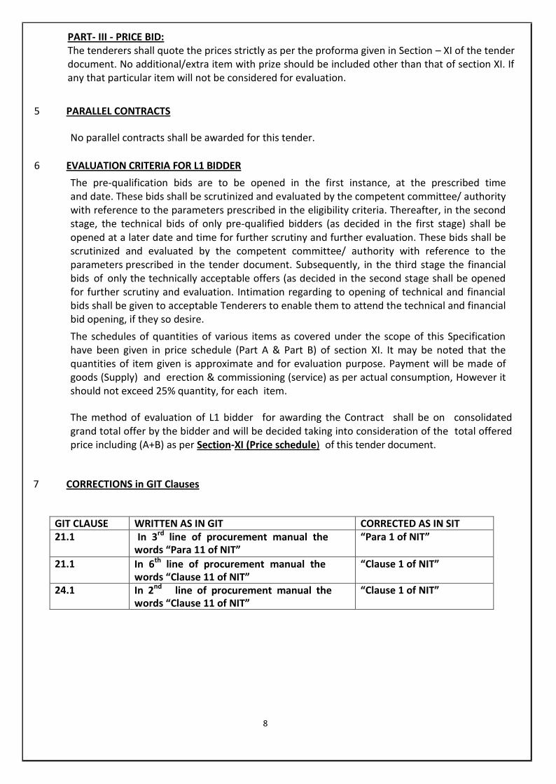
PART- III - PRICE BID:The tenderers shall quote the prices strictly as per the proforma given in Section – XI of the tenderdocument. No additional/extra item with prize should be included other than that of section XI. Ifany that particular item will not be considered for evaluation.
5 PARALLEL CONTRACTS
No parallel contracts shall be awarded for this tender.
6 EVALUATION CRITERIA FOR L1 BIDDERThe pre-qualification bids are to be opened in the first instance, at the prescribed timeand date. These bids shall be scrutinized and evaluated by the competent committee/ authoritywith reference to the parameters prescribed in the eligibility criteria. Thereafter, in the secondstage, the technical bids of only pre-qualified bidders (as decided in the first stage) shall beopened at a later date and time for further scrutiny and further evaluation. These bids shall bescrutinized and evaluated by the competent committee/ authority with reference to theparameters prescribed in the tender document. Subsequently, in the third stage the financialbids of only the technically acceptable offers (as decided in the second stage shall be openedfor further scrutiny and evaluation. Intimation regarding to opening of technical and financialbids shall be given to acceptable Tenderers to enable them to attend the technical and financialbid opening, if they so desire.The schedules of quantities of various items as covered under the scope of this Specificationhave been given in price schedule (Part A & Part B) of section XI. It may be noted that thequantities of item given is approximate and for evaluation purpose. Payment will be made ofgoods (Supply) and erection & commissioning (service) as per actual consumption, However itshould not exceed 25% quantity, for each item.
The method of evaluation of L1 bidder for awarding the Contract shall be on consolidatedgrand total offer by the bidder and will be decided taking into consideration of the total offeredprice including (A+B) as per Section-XI (Price schedule) of this tender document.
7 CORRECTIONS in GIT Clauses
GIT CLAUSE WRITTEN AS IN GIT CORRECTED AS IN SIT21.1 In 3rd line of procurement manual the
words “Para 11 of NIT”“Para 1 of NIT”
21.1 In 6th line of procurement manual thewords “Clause 11 of NIT”
“Clause 1 of NIT”
24.1 In 2nd line of procurement manual thewords “Clause 11 of NIT”
“Clause 1 of NIT”
8
8 CO-ORDINATION WITH STATUTORY BODIES AND OUTSIDE AGENCIES
The Contractor shall be fully responsible for carrying out all co-ordination & liaison work as maybe required with Boiler Inspector, IBR statutory bodies & other statutory bodies forimplementation of the work. The application on behalf of the Owner for submission to the BoilerInspector, IBR Statutory bodies & other statutory bodies along with copies of drawings, data, DBR…etc complete in all respects shall be done by the Contractor & approval/certificates taken wellahead of time so that the actual commissioning of equipment is not delayed for want ofinspection and approval by the Inspector & statutory bodies. The actual inspection work by theBoiler Inspector shall be arranged by the Contractor.
However, official fees paid to Boiler Inspector, IBR Statutory bodies / other statutory bodies, etc.in this regard shall be borne by the SPM.
9

(Section – IV)
GENERAL CONDITIONS OF CONTRACT (GCC)
Kindly refer http://spmhoshangabad.spmcil.com/spmcil/uploaddocument/GCC.pdf for further details.(GCC contains 28 Pages)
10
(Section – V)
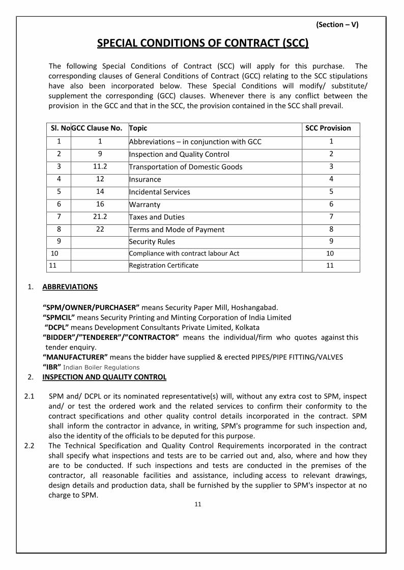
SPECIAL CONDITIONS OF CONTRACT (SCC)
The following Special Conditions of Contract (SCC) will apply for this purchase. Thecorresponding clauses of General Conditions of Contract (GCC) relating to the SCC stipulationshave also been incorporated below. These Special Conditions will modify/ substitute/supplement the corresponding (GCC) clauses. Whenever there is any conflict between theprovision in the GCC and that in the SCC, the provision contained in the SCC shall prevail.
Sl. NoGCC Clause No. Topic SCC Provision
1 1 Abbreviations – in conjunction with GCC 12 9 Inspection and Quality Control 23 11.2 Transportation of Domestic Goods 34 12 Insurance 45 14 Incidental Services 56 16 Warranty 67 21.2 Taxes and Duties 78 22 Terms and Mode of Payment 89 Security Rules 9
10 Compliance with contract labour Act 10
11 Registration Certificate 11
1. ABBREVIATIONS
“SPM/OWNER/PURCHASER” means Security Paper Mill, Hoshangabad.“SPMCIL” means Security Printing and Minting Corporation of India Limited“DCPL” means Development Consultants Private Limited, Kolkata
“BIDDER”/”TENDERER”/”CONTRACTOR” means the individual/firm who quotes against thistender enquiry.
“MANUFACTURER” means the bidder have supplied & erected PIPES/PIPE FITTING/VALVES“IBR” Indian Boiler Regulations
2. INSPECTION AND QUALITY CONTROL
2.1 SPM and/ DCPL or its nominated representative(s) will, without any extra cost to SPM, inspectand/ or test the ordered work and the related services to confirm their conformity to thecontract specifications and other quality control details incorporated in the contract. SPMshall inform the contractor in advance, in writing, SPM's programme for such inspection and,also the identity of the officials to be deputed for this purpose.
2.2 The Technical Specification and Quality Control Requirements incorporated in the contractshall specify what inspections and tests are to be carried out and, also, where and how theyare to be conducted. If such inspections and tests are conducted in the premises of thecontractor, all reasonable facilities and assistance, including access to relevant drawings,design details and production data, shall be furnished by the supplier to SPM's inspector at nocharge to SPM.
11

2.3 If during such inspections and tests the contracted work fail to conform to the requiredspecifications and standards, the inspector may reject them and the contractor shall eitherreplace the rejected work or make all alterations necessary to meet the specifications andstandards, as required within the original delivery period and as specified in the contract free ofcost to SPM and resubmit the same to the inspector for conducting the inspections and testsagain.
2.4 In case the contract stipulates pre-despatch inspection of the ordered work at contractor’spremises, the contractor shall put up the work for such inspection to SPM’s or DCPL’sInspector well ahead of the contractual delivery period, so that the inspector is able to completethe inspection within the contractual delivery period.
2.5 If the contractor tenders the goods to the inspector for inspection at the last momentwithout providing reasonable time to the inspector for completing the inspection within thecontractual delivery period, the inspector may carry out the inspection and complete theformality beyond the contractual delivery period at the risk and expense of the contractor.The fact that the goods have been inspected after the contractual delivery period will not havethe effect of keeping the contract alive and this will be without any prejudice to the legal rightsand remedies available to SPM under the terms & conditions of the contract.
2.6 Work accepted by SPM and/ or its inspector at initial inspection and in final inspection in termsof the contract shall in no way dilute SPM's right to reject the same later, if found deficient interms of the warranty clause of the contract, as incorporated under GCC Clause.
2.7 Travelling expenses, Lodging and boarding charges of SPM officer for pre-shipment inspectionshall be borne by SPM.
3. TRANSPORTATION OF DOMESTIC GOODS
The supplier shall arrange transportation of the ordered goods up to the SPM and furthertransportation up to the Project site.
4. INSURANCE
4.1 The Supplier shall arrange for insuring the goods the goods against loss or damage incidentalto manufacture or acquisition, transportation, storage and delivery in the following manner.
4.2 The supplier shall be responsible till the entire stores contracted for arrive in good conditionat destination. The transit risk in this respect shall be covered by the Supplier by gettingthe stores duly insured till unloading of the stores at site. The insurance cover shall be obtainedby the Supplier in its own name and not in the name of SPM or its Consignee.
4.3 Insurance in respect of damages to persons and property during equipment erection:
4.3.1 The Contractor shall be responsible for all injury or damage to persons, animals or things andfor all damage to property which may arise from any factor omission on the part of theCONTRACTOR or any of their employees. The liability under this clause shall cover also inter-aliaany damage to structures, whether immediately adjacent to the works or otherwise, anydamage to roads, streets, footpaths, bridges as well as damage caused to the building and otherstructures and works forming the subject matter of this contract. The Contractor shall also beresponsible for any damage caused to the buildings and other structures and works forming thesubject matter of this contract due to rain, wind, frost or other inclemency of weather.
12

The Contractor shall indemnify and keep indemnified the SPM and hold him harmless in respectof all and any loss and expenses arising from any such injury or damage to persons or propertyas aforesaid and also against any claim made in respect of injury or damage, whether under anystatute or otherwise and also in respect of any award or compensation or damageconsequent upon such claims. The Contractor shall, at his own expense, effect and maintaintill issue of the virtual completion certificate under this contract, with an insurance companyapproved by the SPM, an All Risks Policy for Insurance for the full amount of the contractincluding earth quake risk in the joint names of the SPM and the Contractor (the name of theformer being placed first in the policy) against all risks as per the standard all risk policy forContractor’s and deposit such policy or policies with SPM before commencing the works.
4.3.2 The Contractor shall reinstate all damage of every sort mentioned in this clause so as to dodelivery of the whole of the works complete and perfect in every respect and so as to makegood or otherwise satisfy all claims for damage to property or third parties.
4.3.3 The Contractor shall also indemnify and keep indemnified the SPM against all claims which maybe made against the SPM by any person in respect of anything which may arise in respect of theworks or in consequence thereof and shall at his own expense, effect and maintain until thevirtual completion of the contract, with an Insurance Company approved by the SPM a policyof Insurance in the joint names of the SPM and the Contractor (name of the former beingplaced first in the policy) against such risks and deposit such policy or policies beforecommencement of the works.
4.3.4 The minimum limit of the coverage under the policy shall be Rs.2 Lakhs per person for any oneaccident or occurrence and Rs.5 Lakhs in respect of damage to property for any one accident oroccurrence. The Contractor shall also indemnify the SPM against all claims which may be madeupon the SPM, whether under the Workmen’s Compensation Act or any other
4.4 Statute in force, during the currency of this contract or at Common Law in respect of anyemployee of the Contractor and shall be at his own expense, effect and maintain until theVirtual Completion of the Contract with an Insurance Company approved by the SPM a policy ofInsurance against such risks and deposit such policy or policies with the SPM from time to timeduring the currency of this contract.
4.4.1 In default of the Contractor insuring as provided above, the SPM may so insure and may deductthe premiums paid from any money due or which may become due to the Contractor.
4.4.2 The Contractor shall be responsible for any liability which may not be covered by the insurancepolicies referred to above and also for all other damages to any person, animal or defectivecarrying out of this contract, whatever, may be the reasons due to which the damage shall havebeen caused.
4.4.3 The Contractor shall also indemnify and keep indemnified the SPM against all and anycosts, charges or expenses arising out of any claim or proceedings relating to the works andalso in respect of any award of damage or compensation arising there from.
4.4.4 Without prejudice to the other rights of the SPM against Contractors in respect of such default,the SPM shall be entitled to deduct from any sums payable to the Contractor the amount of anydamages, compensation costs, charges and other expenses paid by SPM and which are payableby the Contractor under this clause.
13

4.4.5 The Contractor shall upon settlement by the insurer of any claim made against the insurerpursuant to a policy taken under this clause, proceed with due diligence to rebuild or repair theworks destroyed or damaged. In this event all the money received from the insurer in respect ofsuch damage shall be paid to the Contractor and the Contractor shall not be entitled to anyfurther payment in respect of the expenditure incurred for rebuilding or repairing of thematerials or goods destroyed or damaged.
4.4.6 The Contractor, in case of re-building or reinstatement after damage shall be entitled tosuch extension of time for completion as SPM and/ or DCPL may deem fit, but shall, however,not be entitled to reimbursement by SPM of any shortfall or deficiency in the amount finallypaid by the insurer in settlement of any claim arising as set out herein.
5. INCIDENTAL SERVICES5.1 Subject to the stipulation in the Technical Specification (Section - VII); the supplier shall be
required to perform all of the following services.
a) Providing required jigs and tools for assembly, start-up and maintenance of the goods.
b) Supplying required number of operation & maintenance manual for the goods.c) Installation and commissioning of the goods.d) Training of SPM’s operators for operating and maintaining the goods.e) Providing after sales service during the tenure of the contract.f) Providing maintenance service after expiry of the warranty period of the goods if so
incorporated in the contract.6. WARRANTY
6.1 The supplier warrants that the goods supplied under the contract is new, unused andincorporate all recent improvements in design and materials unless prescribed otherwise bySPM in the contract. The supplier further warrants that the goods supplied under the contractshall have no defect arising from design, materials (except when the design adopted and / orthe material used are as per SPM's specifications) or workmanship or from any act or omissionof the supplier, that may develop under normal use of the supplied goods under the conditionsprevailing in India.
6.2 This warranty shall remain valid for twelve months after the goods or any portion thereof asthe case may be, have been delivered to the final destination and installed and commissionedat the final destination and accepted by SPM in terms of the contract or for eighteen monthsfrom the date of despatch from the supplier's premises whichever is later.
6.3 In case of any claim arising out of this warranty, SPM shall promptly notify the same in writingto the supplier.
6.4 Upon receipt of such notice, the supplier shall, with all reasonable speed and time, repair orreplace the defective goods or parts thereof, free of cost, at the ultimate destination. Thesupplier shall take over the replaced parts/ goods after providing their replacements and noclaim, whatsoever shall lie on SPM for such replaced parts/ goods thereafter.
6.5 In the event of any rectification of a defect or replacement of any defective goods during thewarranty period, the warranty for the rectified/ replaced goods shall be extended to a furtherperiod of twelve months from the date such rectified / replaced goods starts functioning to thesatisfaction of SPM.
14
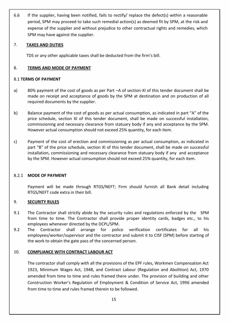
6.6 If the supplier, having been notified, fails to rectify/ replace the defect(s) within a reasonableperiod, SPM may proceed to take such remedial action(s) as deemed fit by SPM, at the risk andexpense of the supplier and without prejudice to other contractual rights and remedies, whichSPM may have against the supplier.
7. TAXES AND DUTIES
TDS or any other applicable taxes shall be deducted from the firm’s bill.
8. TERMS AND MODE OF PAYMENT
8.1 TERMS OF PAYMENT
a) 80% payment of the cost of goods as per Part –A of section-XI of this tender document shall bemade on receipt and acceptance of goods by the SPM at destination and on production of allrequired documents by the supplier.
b) Balance payment of the cost of goods as per actual consumption, as indicated in part “A” of theprice schedule, section XI of this tender document, shall be made on successful installation,commissioning and necessary clearance from statuary body if any and acceptance by the SPM.However actual consumption should not exceed 25% quantity, for each item.
c) Payment of the cost of erection and commissioning as per actual consumption, as indicated inpart “B” of the price schedule, section XI of this tender document, shall be made on successfulinstallation, commissioning and necessary clearance from statuary body if any and acceptanceby the SPM. However actual consumption should not exceed 25% quantity, for each item.
8.2.1 MODE OF PAYMENT
Payment will be made through RTGS/NEFT; Firm should furnish all Bank detail includingRTGS/NEFT code extra in their bill.
9. SECURITY RULES
9.1 The Contractor shall strictly abide by the security rules and regulations enforced by the SPMfrom time to time. The Contractor shall provide proper identity cards, badges etc., to hisemployees whenever directed by the DCPL/SPM.
9.2 The Contractor shall arrange for police verification certificates for all hisemployees/worker/supervisor and the contractor and submit it to CISF (SPM) before starting ofthe work to obtain the gate pass of the concerned person.
10. COMPLIANCE WITH CONTRACT LABOUR ACT
The contractor shall comply with all the provisions of the EPF rules, Workmen Compensation Act1923, Minimum Wages Act, 1948, and Contract Labour (Regulation and Abolition) Act, 1970amended from time to time and rules framed there under. The provision of building and otherConstruction Worker’s Regulation of Employment & Condition of Service Act, 1996 amendedfrom time to time and rules framed therein to be followed.
15
11. REGISTRATION CERTIFICATE
The contractor should be registered & established in the business of design, Engineering,Fabrication, Manufacture, testing, Supply, Erection and Commissioning of pipes/Pipefittings/Valves System. Copy of the registration certificate / Incorporation to be furnished by thebidder.
16

(Section – VI)LIST OF REQUIREMENTS
ScheduleNo.
Brief description of work and services(Related specifications etc. are inSection-VII)
Accountingunit
Quantity Amount ofEarnestMoney
1. Supply, transportation from stockyard,pre-assembly at site, consumablematerials, complete erection, testingand successful commissioning of IBRPipes and Pipe Fittings, Flanges,Valves, etc., including pipe supportingarrangements, as specified underSection – VII complete with all fittings
ReferAppendix-Bof Section VII
ReferAppendix-Bof Section VII
Rs.1,70,000/- (Rs.One LakhSeventythousand only)
Required Completion Schedule : Five (5) months from the date of issue of Notification ofAward of contract or Purchase Order whichever is earlier.(including Supply, Erection & Commissioning)
Required Terms of Delivery : F.O.R SPM Hoshangabad (Duly Unloaded)Preferred Mode of Transportation : Roadways
1. DETAIL SCOPE OF SUPPLY
The detail scope of supply of the Tenderer for this Tender shall include the following:
1.1 SCOPE OF SUPPLY
The scope of supply of the Tenderer covered under this specification shall include the following:
1.1.1 A l l p iping, valves, fittings, specialties, hangers and supports etc for steam services outside thebattery limit of different package Vendors as per the details incorporated within following Appendiceswhich form integral Part of this Specification :
a) Appendix - A : Site and Mill Services Data
b) Appendix - B : Schedule of Piping Materials.
c) Appendix – C : Schedule of Valves
d) Appendix - D : Mechanical Standards
e) Appendix – G : Schedule of Work Item
17

1.1.2 All materials i.e. insulation, aluminium cladding, wires, plaster polythene sheets, insulation supports,etc. as specified herein to insulate the Piping/Fittings/Flanges/Valves, etc.
1.1.3 Insulation thickness shall be provided as per charts attached herein with.
f) Appendix - E : Insulation Thickness Table
g) Appendix – F : Insulation Schedule
1.2 SCOPE OF SERVICES
1.2.1 The successful Tenderer under this specification shall be responsible for the completeerection, supervision, testing, commissioning .
1.2.2 The Tenderer shall arrange for supply of all labour (supervisor, skilled, unskilled and administrative),transport vehicles, erection tools and tackles, radiography & stress relieving equipment as may berequired for the efficient & timely execution of the contract. All consumable materials includingwelding electrode and gases, oils and greases, cleaning and anticorrosive fluids and all othernecessary materials required during erection.
1.2.3 Opening of packing cases, inspection & checking of materials for their completeness and condition.No packing case shall however be opened except in presence of SPM/DCPL authorizedrepresentative.
1.2.4 Once the materials are inspected, the same shall be stored by the Contractor near the place oferection, as required or directed Purchaser’s representative, adequately protected from theft anddeterioration or damage by rain, storm, dust water, tampering by casual visitors or workers. Anydamage or loss through theft shall be to Contractor’s account free of cost.
1.2.5 SPM will make available the following items free of cost to the successful Tenderer :Power, Air & Water required for testing and commissioning.However, successful Tenderer shall send prior intimation to the SPM indicating the details of aboveutility requirement for testing and commissioning.
1.2.6 All required labour, tools, equipment and transportation thereof and to insulate piping, vessels andequipment as defined in insulation schedule.
1.2.7 To protect adjacent equipment, pavements and other properties from scrap insulation, dripped orsprayed paint, asphalt etc. and to clean up the area after completion of his work, removing allunused insulation material, scaffolding, etc. provided by him or supplied to him by the purchaser.
2. SAFETY AND HEALTH INSTRUCTIONS
During installation, the Contractor shall follow all the Safety Policy and Plant Safety rules of SPMand also the various provisions of M.P. Factories Rules, 1962 made under Factories Act, 1948.
This instruction gives broad guidelines to be followed by the Contractor for ensuring safeworking conditions in and around the site.
18

2.1 SAFETY ORGANISATIONContractor at site shall organize a Safety Group headed by a Safety Officer who shall beresponsible for providing, supervising and monitoring safe working conditions at all times fortheir workers. The Safety Officer shall be experienced in maintaining safe conditions for workersat site and shall be responsible for and shall have authority to enforce safe conditions for theworkers.Contractor shall have a declared Safety Policy and shall get the same approved by the SPM and/orDCPL. The approved Safety Policy shall be displayed prominently in the Contractor’s site office.Contractor shall take active interest and participate in the development and operation of safetyprograms at site. His responsibility does not cease with establishment of Safety Group and
approval of its various activities. He shall demonstrate his involvement by regular participation insafety meetings, review of safety records and taking corrective action where required,introduction of safety promoting bulletins, posters, suggestions and awards and by settingexample by strictly observing safety rules.
Contractor shall remove all waste material and debris from and around the work area andproperly clean up the area at the end of each day before leaving the work site.The Contractor shall take all necessary precautions not only for safe working of his ownworkmen but also deploy all precautions to ensure safety of structures, equipment and workmenof other agencies in and around his work site. The Contractor shall ensure that his workmen donot trespass into prohibited areas.
SPM and/or DCPL shall have the right to inspect at any time, all items of machinery orequipment brought to site by the Contractor, his agents or workmen and to prohibit the use onthe site of any item, which in the opinion of the SPM and/or DCPL is or may be detrimental tothe safety of the site. The exercise of such right or the omission to exercise it in any particularcase shall not absolve the Contractor or his agents or workmen of their responsibility of adheringto the safe working practices.Contractor shall execute the work in a manner causing the least possible interference with thebusiness of the SPM and/or DCPL, or with the work of any other Contractor who may beengaged on the premises and shall at all times co-operate with the other Contractors working atsite.Contractor shall obtain work permit from the SPM and/or DCPL before starting any work atsite. The work permits are issued to prevent the Contractor from working in un-authorized areasand shall be valid for specific area for a stipulated period.The Contractor shall ensure at all times that his workers do not lie down or sleep under oraround any machine, equipment, vessel, vehicle or structures in his work area.
2.2 RESPONSIBILITIES OF THE CONTRACTOR’S SAFETY OFFICER
He is responsible and accountable for:a) Preventing injury to personnel, damage to plant and equipment and fires.b) Instituting ways to improve existing work methods from safety point of view.c) Legal and contractual requirements affecting safety, health, and welfare of his workmend) Provision and use of protective clothing and equipment and use of fire fighting equipmente) Suitability of new and hired equipment from a safety viewpointf) Identifying potential hazards.g) Changes in safety requirements and fire precautions
19

h) Carrying out site surveys to see that only safe work methods are in operation, health andsafety requirements are being observed and welfare and first aid facilities are adequate andproperly maintained.
i) Determining the cause of an accident or dangerous occurrence and recommend means ofpreventing recurrence.
j) Supervising the recording and analysis of information on injuries, damage and productionloss. Assess accident trends and review overall safety performance.
k) Assisting with training of employees at all levels. Organizing periodic demonstration ofpracticing safe working conditions by experienced safety instructors.
l) Taking part in discussions on injury, damage and loss control.m) Keeping up-do-date with recommended codes of practice and safety literature.
Circulating information applicable to each level of employees.n) Fostering within the company an understanding that injury prevention and damage control
are an integral part of business and operational efficiency.o) Attending job progress meetings where safety is an item on the agenda. Report on job safety
performance.The Safety Officer shall inspect and ensure the following:
a) All electrical equipments are securely earthed.b) Standard access platforms and ladders are provided for inspection, operation and
maintenance of equipment.c) The equipment are periodically inspected for their condition, maintained properly and
operated by trained personnel at design speeds and loads.
2.3 WORKING AT HEIGHTS
For carrying out work at heights exceeding 2 meters or near openings in floors and roofsetc. precautions as given in following para shall be taken.Adequate safety precautions like use of safety belts, crawling-ladders, safety nets etc. shallbe taken. The workers shall wear safety belts with hook properly fastened.All workmen engaged on work at heights shall be experienced in such work.Written permission of the SPM and/or DCPL shall be obtained before undertaking work on roofs.Wherever possible, steel staging or platform shall be erected.Staging with toe guards shall be provided with simple safety rails or ropes at waist heightthroughout its length on all open sides.Staging supports shall be All Purpose Scaffolding (APS) steel tubes scaffolding, safety secured andsupported on firm level footings or slung from overhead beams. The supports shall be situatedat maximum distance of 2.5 meters apart and the staging shall be secured to each support.Wherever it is not possible to put up staging and/or use of safety belts, safety nets shall beslung beneath the place of work for safety.When working over open process vessels or tanks, safety belts and safety nets shall alwaysbe used whether or not staging and scaffolding is provided.Safe access to all points of works shall be provided in the form of suitable ladders and stairwaysetc. Area around the work place shall be barricaded suitably or fenced off to avoid injuries topersonnel passing by. Suitable warning boards and signs shall be put up.
2.4 LIFTING GEAR
The Contractor shall submit a valid Test Certificate to the SPM and/or DCPL, from approvedcertifying authorities for all of his lifting gear and hoists, slings, chains, wire ropes, hooks, chain-pulley blocks, winches, hoists and cranes etc. before commencing work.These certificates shall be available at site in the Contractor’s office for inspection as and whenrequired.
20
2.5 PRESSURE AND LEAK TESTINGPressure and leak testing of equipment shall be carried out hydraulically. However, in specialcases where pneumatic testing is specified, written approval shall be obtained from the SPMand/or DCPL before starting work. Under no circumstance gases other than nitrogen, carbondioxide, air or steam shall be used for testing.In case nitrogen or carbon dioxide is used for testing, the equipment shall be adequatelyventilated and gas tested to ensure oxygen content of 21% before permitting a worker to enterthe equipment.
2.6 WORKS INSIDE AN EQUIPMENT OR DRAINAGE SYSTEM
All equipment and associated piping shall be isolated, completely drained, purged andwell ventilated before entry of a worker. The atmosphere inside the vessel or equipment shallbe tested to ensure absence of toxic and flammable gases.Toxic and flammable liquids and gases in the equipment shall be safely disposed of as per thestatutory requirements to the satisfaction of the SPM and/or DCPL.Workers carrying out drainage, purging and testing operations shall wear gas masks and otherprotective gear appropriate to the material being handled.
While a worker has entered equipment or a drainage system, another worker shall be presentoutside at all times to assist the worker inside in the event of an emergency.
2.7 ELECTRICAL
Portable power tools rated for above 50 V supply and hand lamps rated for above 24 V supply shallnot be used at site.
An armoured cable with a 3 pin Reyrolle type plug, properly earthed shall be provided between theContractor’s DG set and step down transformer.
All power supply and distribution boards shall have canopy for protection and all the distributionboards shall be earthed securely.All supply points shall have proper plug and socket.
The Contractor shall check tightness of connection of cable terminations and joints before startingthe work.
2.8 WELDING
Only qualified welders shall be employed at the work site. The Contractor shall organise thequalifying test at site for his welders and the SPM and/or DCPL shall approve the welders. Allwelders shall have to undergo qualifying test and only on passing the test, they shall be allowedto work at site. The welders engaged for erection and commissioning work shall be IBR approved.For all welding work at site, generator sets shall be used instead of AC transformer sets.AC Transformer sets are banned for welding jobs inside vessels (both open and closed top type).The Contractor shall get his welding sets certified by the SPM and/or DCPL before starting work.These certificates shall have to be renewed every two months. A copy of the certificates shall bedisplayed on respective welding sets.Only cables in good condition and insulated holders shall beused. The length of supply cable to welding site shall not exceed 8 metres and the welding setbody shall be properly earthed.A charged fire extinguisher of CO2 type shall be carried with eachwelding set. The Contractor shall keep Halon or equivalent type fire extinguishers near hot jobslike cutting oil lines.The welder shall not use a building structure, pipeline or railway track etc. asa return path of the current. Adequately rated circuit breaker shall be provided in the powercircuit for human protection on all power supply points.
21
2.9 HOT WORK
Before starting any hot work like gas cutting, welding and grinding etc., the Contractor shallobtain hot work permit from the SPM and/or DCPL. The permit shall be renewed on day-to-daybasis.The Contractor shall ensure purging of piping and equipment to make it totally safe beforecarrying out any hot work.Smoking is strictly prohibited in work areas inside the SPM premisesNo combustible material shall be stored on or near any source of heat like hot pipes, welding orgas. Before leaving the place of work or the Contractor’s sheds, the Contractor’s workmen shallensure that no material or item that could start a fire is left at site. Special attention shallbe paid to collection and disposal of oil soaked cotton waste or rags. On no account are these tobe dropped into corners, pushed below equipment or left hanging on pipes.Gas cylinders shall be used in a safe manner. These shall not be dropped from heights or draggedon the floor. Trolley with rubber rimmed wheels shall be used for transporting gas cylinderswithin the site. Acetylene cylinders shall be kept in upright position. Oxygen cylinders shall notbe kept near inflammable materials like oil etc.Tarpaulins shall not be used in the vicinity of welding and gas cutting jobs.The Contractor’s supervisor of the rank of a foreman or equivalent shall examine thearrangements made for hot work before commencement of work and shall satisfy him that allreasonable safety precautions have been taken.The Contractor shall return the hot work permit after completion of welding work.
2.10 PERSONAL PROTECTIVE EQUIPMENT
Workmen at site shall wear protective clothing, head, leg and eye protection safety equipment atall times as per the job requirements. These are to be supplied and provided by the Contractor.Adequate number of IS approved safety helmets shall be available at site.Welders shall wear good quality insulated welding gloves, goggles, face shield, shoes and overallswhile at work.
2.11 ACCIDENTSIn case of injury or serious illness of a worker, the DCPL/SPM shall be notified immediately. Allaccidents shall be recorded by filling in the ‘Accident Report’ form, which shallbe kept in easy accessible location in the site office of the Contractor. Any ‘Near Miss’ incidentshall also be reported by the Contractor and recorded.
2.12 INSURANCEAll the Contractor’s workmen shall be covered under the Employees State Insurance Scheme,Medi Claim Policy or any other scheme which may be specified by the Statutory Authorities fromtime to time.
2.13 REVIEW MEETINGThe SPM and/or DCPL shall conduct fortnightly Safety Review Meeting to review the safetyconditions practised at work areas by the Contractor.
2.14 WORK AFTER NORMAL WORKING HOURSExtra care shall be taken for jobs to be carried out after normal working hours with duerevalidated work permit and supervised by the Contractor’s site in-charge. The site-in-charge shall make available his residential address and telephone number to the SPM and/orDCPL so that he can be contacted in case of an emergency.Proper lighting shall be ensured at the workplace for any work carried out after the normalworking hours.
22
2.15 CONVEYANCE FOR EMERGENCY
The Contractor shall ensure that conveyance and person with driving license is available at siteat all times of work execution so that in case of an accident, the victim can be rushed tonearest medical centre.
2.16 SAFETY PRACTICESAvoid working under un-insulated live conductors or working on freshly painted steel, which is stillwet.Stairs and railing shall be in place as long as necessary. Ladders shall be periodically checked forany defects. Ladders shall be securely fastened to prevent movement while in use.The Contractor shall advise his workmen to take the following precautions while using ladders:a) While ascending or descending, face the ladder. Use both hands for holding.b) Do not climb higher than the third rung from top on straight or extension-ladders and
second rung from top on set ladders.c) Step-ladders shall be fully open before use.d) Sliding down a ladder shall be prohibited.e) Make shift ladders such as clear fastened across a single rail and short ladders spliced
together shall never be used.f) Ladders shall be kept free from dirt and grease.g) Defective ladders shall be removed from use.h) Ladders shall not be left un-attended unless these are securely anchored at top and bottom.i) While using ladders, shoes shall not be greasy, muddy or otherwise slippery.j) Ladder shall not be used during severe windy conditions.
Lumber shall be piled out of the work area. Nails shall be removed or bent while handling lumberto avoid injury to workmen.While tearing down plaster or brickwork, dust shall be controlled with water.Walls shall not be subjected to lateral pressure or impact from materials stored or fallingmaterials. The safety valves for boilers shall be set by trained personnel and shall be sealed orpadlocked at safe working pressure. Only authorized person shall change the setting of safetyvalves. The safety valve relieving pressures shall be checked as recommended by themanufacturer and applicable codes.Blow down valves shall be operated strictly as per instructions. If blow cock is not marked withan arrow to show open and close position, the same shall be marked at site.Safety slogans and safety instructions shall be prominently displayed in English, Hindi andlocal language at strategic locations.
2.17 EMERGENCY PROCEDURES
The Contractor shall familiarize himself with the emergency procedures, which apply to plantsand areas in which his men are working.First Aid Box shall be kept in the Contractor’s site office. The Contractor’s site-in-charge and hiskey supervisors shall be trained in administering first aid, preliminary treatment for electricalshocks, fall from height and burns etc.When an emergency condition exists or on hearing the ‘Stop Work Alarm’ every supervisorshall ensure:a) All work is stopped at once.b) All equipment is shutdown.c) All men are evacuated to a pre-determined assembly point.d) A roll call is taken and every man is accounted for.e) No one shall be permitted to return to work until notification has been received from
a responsible authorised agency that it is safe to do so.
23

2.18 RESPONSIBILITY OF THE CONTRACTOR’S SITE IN CHARGE
His primary responsibility is safety of personnel and equipment. He shall:Understand the company’s policy on maintaining safe working environment and appreciatethe responsibility allocated to each grade of supervision.Know the safety requirements and relevant Government Regulations, and ensuretheir implementation.Ensure that sound, safe working methods and reasonable welfare facilities are provided forworkers. Determine at the planning stage the following:
2.18.1 The most appropriate order and method of working2.18.2 Allocation of responsibilities to supervisors2.18.3 Storage areas and access etc.2.18.4 Hazards which may arise from overhead or underground services2.18.5 Facilities for welfare, first aid and sanitation2.18.6 Work permits procedures and requirements2.18.7 Basic fire precautions2.18.8 Provide written instructions to establish work methods, to explain the sequence of
operations, to outline potential hazards at each stage and to indicate precautions to be adopted.
2.19 TIME SCHEDULE
2.19.1 The work shall be executed strictly as per the time schedule given in this Bid Document.
2.19.2 The Bidder shall furnish a proposed time schedule by CPM/bar-chart along with hisquotation. The time schedule should indicate the details considering the date of issue of Letterof Intent as the zero date and should show completion of various activities there from.
2.19.3 The time schedule shall clearly include all important events regarding engineering,procurement, construction, testing and handing over for each area, commensurate with theoverall time schedule.
2.19.4 The time schedule shall form a part of the Contract Document.
2.19.5 BI-WEEKLY Progress reporting shall be done by the Contractor for engineering,procurement and construction activities on mutually agreed formats. Reports on suchformats will be sent regularly in soft copies with six (6) copies of print as per frequency /periodicity agreed upon from time to time.
24

(Section – VII)
TECHNICAL SPECIFICATIONSTABLE OF CONTENTS
CLAUSE NO. DESCRIPTION
1.00.00 INTENT OF SPECIFICATION
2.00.00 SCOPE OF WORK OF TENDERER
3.00.00 SPECIAL CONDITION FOR SUBMISSION OF OFFER
4.00.00 TECHNICAL REQUIRMENT
5.00.00 SPECIAL CONDITION FOR RATES OF CERTAIN ITEMS (SUPPLY)
6.00.00 CERTIFICATION OF CIB (IBR)
7.00.00 CONDITION OF SUPPLY
8.00.00 DRAWINGS/DATA/DOCUMENTS THAT SHALL BE FURNISHED TO THESUCCESSFUL TENDERER
APPENDIX A SITE & MILL SERVICES DATA
APPENDIX B SCHEDULE OF PIPING MATERIALS
APPENDIX C SCHEDULE OF VALVES
APPENDIX D MECHANICAL STANDARDS
APPENDIX E INSULATION THICKNESS TABLE
APPENDIX F INSULATION SCHEDULE
APPENDIX G SCHEDULE OF WORK ITEMS
ANNEXURESI THRU’ III
PROPOSAL SHEET
25
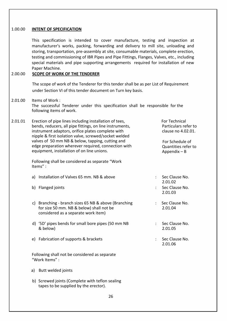
1.00.00 INTENT OF SPECIFICATION
This specification is intended to cover manufacture, testing and inspection atmanufacturer's works, packing, forwarding and delivery to mill site, unloading andstoring, transportation, pre-assembly at site, consumable materials, complete erection,testing and commissioning of IBR Pipes and Pipe Fittings, Flanges, Valves, etc., includingspecial materials and pipe supporting arrangements required for installation of newPaper Machine.
2.00.00 SCOPE OF WORK OF THE TENDERER
The scope of work of the Tenderer for this tender shall be as per List of Requirementunder Section VI of this tender document on Turn key basis.
2.01.00 Items of Work :The successful Tenderer under this specification shall be responsible for thefollowing items of work.
2.01.01 Erection of pipe lines including installation of tees,bends, reducers, all pipe fittings, on line instruments,instrument adaptors, orifice plates complete withnipple & first isolation valve, screwed/socket weldedvalves of 50 mm NB & below, tapping, cutting andedge preparation wherever required, connection withequipment, installation of on line unions.
For TechnicalParticulars refer toclause no 4.02.01.
For Schedule ofQuantities refer toAppendix – B
Following shall be considered as separate “WorkItems” :
a) Installation of Valves 65 mm. NB & above : Sec Clause No.2.01.02
b) Flanged joints : Sec Clause No.2.01.03
c) Branching - branch sizes 65 NB & above (Branchingfor size 50 mm. NB & below) shall not beconsidered as a separate work item)
: Sec Clause No.2.01.04
d) ‘5D’ pipes bends for small bore pipes (50 mm NB& below)
: Sec Clause No.2.01.05
e) Fabrication of supports & brackets : Sec Clause No.2.01.06
Following shall not be considered as separate“Work Items” :
a) Butt welded joints
b) Screwed joints (Complete with teflon sealingtapes to be supplied by the erector).
26

c) Mandatory non-destructive tests required by theapplicable Installation Codes and removal of alltemporary piping & appurtenances like pumps,tanks, hoses etc.
d) Fixing of supports.
e) Setting & final adjustment of spring hangers-variable & constant type . Spring boxes shall besupplied by the Bidder.
f) Supply & installation and subsequent dismantlingof temporary supports required duringtesting/commissioning
g) Fit up of on line hoses
h) Installation of Orifice flanges.
i) Any other item not specificallycalled out as “Separate work item”.
2.01.02 Installation of Valves :(Wafer type, Flanged, S.W. end. Flanged joints forflanged and valves shall be considered as a separatework item. Installation of floor stands & chair wheeloperators shall not be considered as a separate workitem.
2.01.03 Installation of Flanged joints including supply of bolts,nuts & gaskets.
For technical particulars refer toclause no. 4.02.02
For Schedule of quantities refer toAppendix-B
2.01.04 Branching (for branch sizes 65 mm NB & above)including cutting of hole on run pipe, edgepreparation, welding & mandatory testing requiredby applicable codes.
For technical particulars refer toclause no. 4.02.03
For Schedule of quantities refer toAppendix –B
2.01.05 Fabrication of ‘5D’ pipe bends for small bore pipes(50 mm NB & below)
27
For technical particulars refer to clauseno. 4.02.04
For Schedule of quantities refer toAppendix-B

2.01.06 Fabrication and installation of Local Access platformsincluding fixation of support legs on paved/ graded/concrete surfaces. All materials shall be supplied bythe successful Tenderer.
2.01.07 Fabrication of one/two/three/ four cut mitred elbows -‘V’ pieces & crosses.
2.01.08 Contractor may have to carry out small volume ofmiscellaneous work such as.
a) Concreting, Brickwork, Plastering& net cement finish if required by SPM/DCPL(Allmaterials by contractor)
b) Fabrication & fixing of pipe support inserts ifrequired by Purchaser (contingency). All materialsshall be supplied by the successful Tenderer.
c) Fixing of C.S. flanged nozzles on carbon steel tanks(non-pressure) if required by Purchaser(contingency). All materials shall be supplied by thesuccessful Tenderer.
2.01.09 Cleaning/flushing/oiling/steam-blowing/pickling/passivating of pipe lines as may be required forcommissioning of lines. Cleaning/ flushing/ oiling fluidsshall be arranged by the contractor exceptwater/steam which may be arranged by thePurchaser”. All temporary piping required forcleaning/flushing/oiling/steam-blowing shall bearranged by the Contractor. Removal of temporarypiping is also within Contractor’s scope of work.
For technical particulars refer toclause no. 4.02.07
For schedule of quantities refer toAppendix-B
For technical particulars refer toclause no. 4.02.08(a)
For technical particulars refer toclause no. 4.02.08(b)
For technical particulars refer toclause no. 4.02.08(c)
For technical particulars refer toclause no. 4.02.09
28
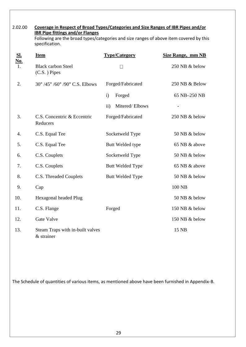
2.02.00 Coverage in Respect of Broad Types/Categories and Size Ranges of IBR Pipes and/orIBR Pipe fittings and/or FlangesFollowing are the broad types/categories and size ranges of above item covered by thisspecification.
Sl.No.
Item Type/Category Size Range, mm NB
1. Black carbon Steel 250 NB & below(C.S. ) Pipes
2. 30° /45° /60° /90° C.S. Elbows Forged/Fabricated 250 NB & Below
i) Forged 65 NB–250 NB
ii) Mitered/ Elbows -
3. C.S. Concentric & EccentricReducers
Forged/Fabricated 250 NB & below
4.
5.
C.S. Equal Tee
C.S. Equal Tee
Socketweld Type
Butt Welded type
50 NB & below
65 NB & above
6.
7.
8.
9.
10.
C.S. Couplets
C.S. Couplets
C.S. Threaded Couplets
Cap
Hexagonal headed Plug
Socketweld Type
Butt Welded Type
Butt Welded Type
50 NB & below
65 NB & above
50 NB & below
100 NB
50 NB & below
11.
12.
13.
C.S. Flange
Gate Valve
Steam Traps with in-built valves& strainer
Forged 150 NB & below
150 NB & below
15 NB
The Schedule of quantities of various items, as mentioned above have been furnished in Appendix-B.
29

3.00.00 SPECIAL CONDITION FOR SUBMISSION OF OFFER
For supply of any item, the same will be completely and uniquely defined by a threepart designation system comprising its Name, Specification Code No. and Size. Forexample : `Pipe', `Spec. code No. 28' and `150 NB' specified a unique item (i.e. pipe)and the same item cannot be specified/ described by any other designation.
4.00.00 TECHNICAL REQUIREMENT
4.01.00 FOR SUPPLY
4.01.01 Technical SpecificationItems covered by this Specification shall be manufactured, inspected, tested, markedand packed as per the technical specifications furnished in enclosed Appendix-D
4.01.02 Schedule of QuantitiesThe schedule of quantities of various items as covered under the scope of thisSpecification have been given in enclosed Appendix-B.
4.02.00 FOR SERVICES
4.02.01 Erection of Pipe Lines :For technical requirements refer to Mechanical standard A4.034.225.3“Fabrication & Installation of carbon Steel, Alloy Steel & Stainless SteelPiping Systems. - General Requirements.”Other miscellaneous requirements are listed below.(a) Instrument adaptors/nipples/first isolation valves/orifice plates shall be installed asper ‘Instrumentation Standards’-
4.02.02 Installation of Flanged Joints :For technical requirements refer to Mechanical Standard No. A4 034.227.3
4.02.03 Branching :
Branching requirements are specified in the “Piping Material Specification” for theproject.Branching (Stub-in) shall be designed according to the applicable” installation code (e.g.ANSI B31.1, IBR ETC.) defined in the “Project Piping Installation specification - Serviceindex.”Branches (Stub-in) shall be reinforced wherever indicated on the drawing.Reinforcement pads shall be cut from the line pipeReinforcement details shall be as per applicable installation code.Contractor shall submit details of branch welding & reinforcement pad for approval..Such details shall show applicable Material Specification Code no./s, size, ranges of runpipe & branch pipe, thickness range of run pipe & branch pipe, and in case of servicesunder IBR, design parameters (i.e. Design Pressure & Temperature).
30
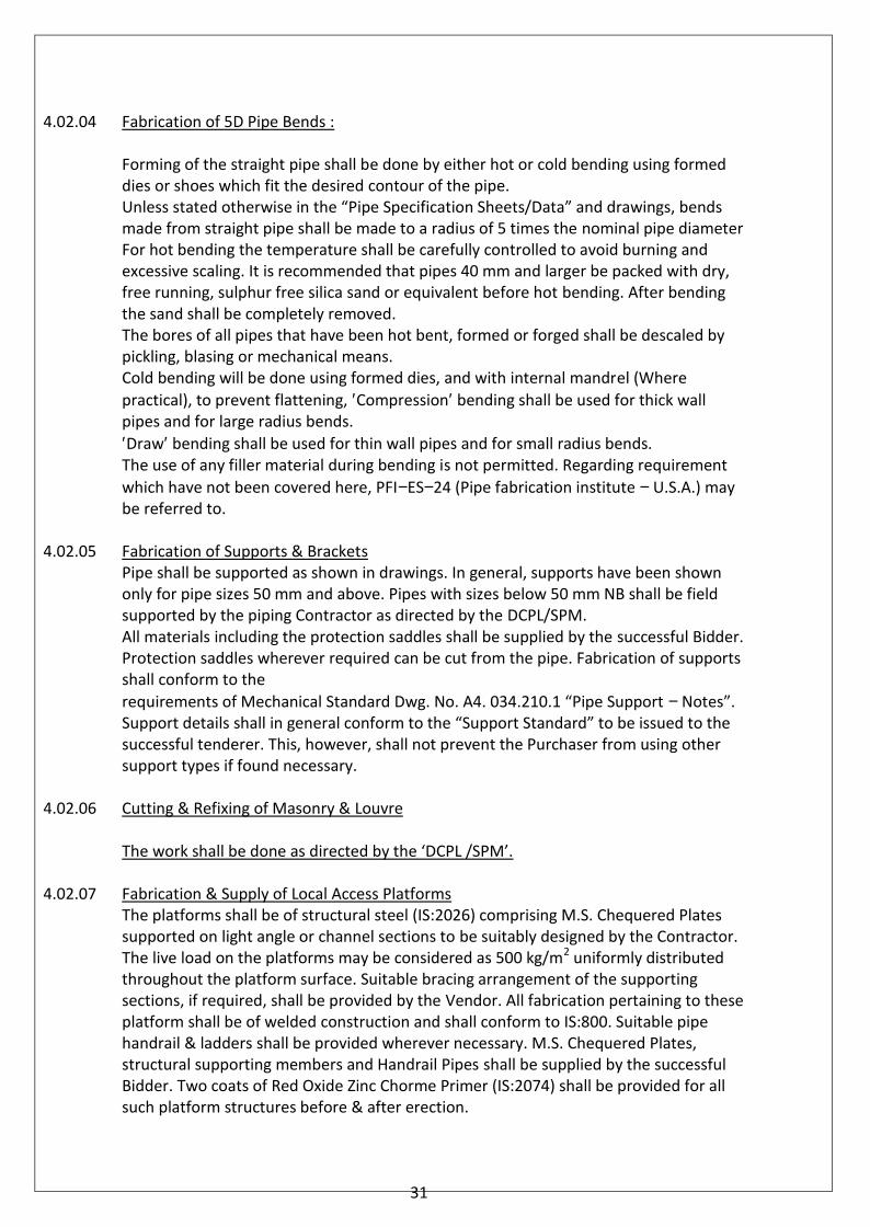
4.02.04 Fabrication of 5D Pipe Bends :
Forming of the straight pipe shall be done by either hot or cold bending using formeddies or shoes which fit the desired contour of the pipe.Unless stated otherwise in the “Pipe Specification Sheets/Data” and drawings, bendsmade from straight pipe shall be made to a radius of 5 times the nominal pipe diameterFor hot bending the temperature shall be carefully controlled to avoid burning andexcessive scaling. It is recommended that pipes 40 mm and larger be packed with dry,free running, sulphur free silica sand or equivalent before hot bending. After bendingthe sand shall be completely removed.The bores of all pipes that have been hot bent, formed or forged shall be descaled bypickling, blasing or mechanical means.Cold bending will be done using formed dies, and with internal mandrel (Wherepractical), to prevent flattening, ′Compression′ bending shall be used for thick wallpipes and for large radius bends.′Draw′ bending shall be used for thin wall pipes and for small radius bends.The use of any filler material during bending is not permitted. Regarding requirementwhich have not been covered here, PFI−ES−24 (Pipe fabrication institute − U.S.A.) maybe referred to.
4.02.05 Fabrication of Supports & BracketsPipe shall be supported as shown in drawings. In general, supports have been shownonly for pipe sizes 50 mm and above. Pipes with sizes below 50 mm NB shall be fieldsupported by the piping Contractor as directed by the DCPL/SPM.All materials including the protection saddles shall be supplied by the successful Bidder.Protection saddles wherever required can be cut from the pipe. Fabrication of supportsshall conform to therequirements of Mechanical Standard Dwg. No. A4. 034.210.1 “Pipe Support − Notes”.Support details shall in general conform to the “Support Standard” to be issued to thesuccessful tenderer. This, however, shall not prevent the Purchaser from using othersupport types if found necessary.
4.02.06 Cutting & Refixing of Masonry & Louvre
The work shall be done as directed by the ‘DCPL /SPM’.
4.02.07 Fabrication & Supply of Local Access PlatformsThe platforms shall be of structural steel (IS:2026) comprising M.S. Chequered Platessupported on light angle or channel sections to be suitably designed by the Contractor.The live load on the platforms may be considered as 500 kg/m2 uniformly distributedthroughout the platform surface. Suitable bracing arrangement of the supportingsections, if required, shall be provided by the Vendor. All fabrication pertaining to theseplatform shall be of welded construction and shall conform to IS:800. Suitable pipehandrail & ladders shall be provided wherever necessary. M.S. Chequered Plates,structural supporting members and Handrail Pipes shall be supplied by the successfulBidder. Two coats of Red Oxide Zinc Chorme Primer (IS:2074) shall be provided for allsuch platform structures before & after erection.
31
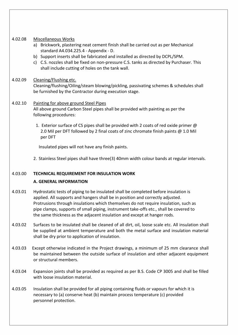
4.02.08 Miscellaneous Worksa) Brickwork, plastering neat cement finish shall be carried out as per Mechanical
standard A4.034.225.4 - Appendix - D.b) Support inserts shall be fabricated and installed as directed by DCPL/SPM.c) C.S. nozzles shall be fixed on non-pressure C.S. tanks as directed by Purchaser. This
shall include cutting of holes on the tank wall.
4.02.09 Cleaning/Flushing etc.Cleaning/flushing/Oiling/steam blowing/pickling, passivating schemes & schedules shallbe furnished by the Contractor during execution stage.
4.02.10 Painting for above ground Steel PipesAll above ground Carbon Steel pipes shall be provided with painting as per thefollowing procedures:
1. Exterior surface of CS pipes shall be provided with 2 coats of red oxide primer @2.0 Mil per DFT followed by 2 final coats of zinc chromate finish paints @ 1.0 Milper DFT
Insulated pipes will not have any finish paints.
2. Stainless Steel pipes shall have three(3) 40mm width colour bands at regular intervals.
4.03.00 TECHNICAL REQUIREMENT FOR INSULATION WORK
A. GENERAL INFORMATION
4.03.01 Hydrostatic tests of piping to be insulated shall be completed before insulation isapplied. All supports and hangers shall be in position and correctly adjusted.Protrusions through insulations which themselves do not require insulation, such aspipe clamps, supports of small piping, instrument take-offs etc., shall be covered tothe same thickness as the adjacent insulation and except at hanger rods.
4.03.02 Surfaces to be insulated shall be cleaned of all dirt, oil, loose scale etc. All insulation shallbe supplied at ambient temperature and both the metal surface and insulation materialshall be dry prior to application of insulation.
4.03.03 Except otherwise indicated in the Project drawings, a minimum of 25 mm clearance shallbe maintained between the outside surface of insulation and other adjacent equipmentor structural members.
4.03.04 Expansion joints shall be provided as required as per B.S. Code CP 3005 and shall be filledwith loose insulation material.
4.03.05 Insulation shall be provided for all piping containing fluids or vapours for which it isnecessary to (a) conserve heat (b) maintain process temperature (c) providedpersonnel protection.

32
4.03.06 Unless otherwise indicated equipments and piping having surface temperature above60OC and not requiring insulation for conservation or other process requirements shall beinsulated for personnel protection, up to a height of 2500 mm from finished grade oroperating platform level and adjacent to and within 600 mm of a walkway, platform orladder.
4.03.07 Steam traps and piping shall be insulated.
4.03.08 Name plates and data plates shall not be insulated. Insulation around markings ornameplates shall be sealed to be weather-proof.
4.03.09 Drain and vent lines in insulated lines downstream of a first block valve shall not beinsulated.
4.03.10 Manholes and hand holes shall not be insulated.Flanges and flanged valves on lines operating below 200OC with the exception of steamlines shall not be insulated. Insulation of pipe shall terminate at such distance from aflanged joint as will allow withdrawal of bolts without disturbing insulation.
4.03.11 Inspection plug shall be provided on pipes to assess corrosion.
B. INSULATION SUPPORTS
4.03.12 Insulation supports for pipes shall be generally as per Mechanical Standard Dwg. No. A-001-013 and the relevant dwg. For insulation application as attached herewith.
4.03.13 Suitable supports in form of rings, lugs, or pins shall be used to supports insulation onpipes. Insulation of vertical piping shall be supported by support rings.
4.03.14 Support rings shall be not less than 3 mm thick. However, the insulation contractor shallprovide the supports wherever any additional support is required.
4.03.15 Except otherwise noted in the attached drawings, spacing of studs, clips of pins used tosupport insulation shall be approximately 600 mm centres for Blanket insulation and oneper block for block insulation. Split pins, if used, shall be spread, bent over and embeddedinto the insulation.
33
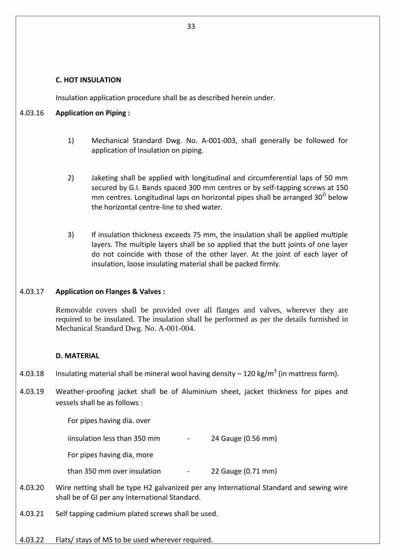
C. HOT INSULATION
Insulation application procedure shall be as described herein under.
4.03.16 Application on Piping :
1) Mechanical Standard Dwg. No. A-001-003, shall generally be followed forapplication of Insulation on piping.
2) Jaketing shall be applied with longitudinal and circumferential laps of 50 mmsecured by G.I. Bands spaced 300 mm centres or by self-tapping screws at 150mm centres. Longitudinal laps on horizontal pipes shall be arranged 30O belowthe horizontal centre-line to shed water.
3) If insulation thickness exceeds 75 mm, the insulation shall be applied multiplelayers. The multiple layers shall be so applied that the butt joints of one layerdo not coincide with those of the other layer. At the joint of each layer ofinsulation, loose insulating material shall be packed firmly.
4.03.17 Application on Flanges & Valves :
Removable covers shall be provided over all flanges and valves, wherever they arerequired to be insulated. The insulation shall be performed as per the details furnished inMechanical Standard Dwg. No. A-001-004.
D. MATERIAL
4.03.18 Insulating material shall be mineral wool having density – 120 kg/m3 (in mattress form).
4.03.19 Weather-proofing jacket shall be of Aluminium sheet, jacket thickness for pipes andvessels shall be as follows :
For pipes having dia. over
iinsulation less than 350 mm - 24 Gauge (0.56 mm)
For pipes having dia, more
than 350 mm over insulation - 22 Gauge (0.71 mm)
4.03.20 Wire netting shall be type H2 galvanized per any International Standard and sewing wireshall be of GI per any International Standard.
4.03.21 Self tapping cadmium plated screws shall be used.
4.03.22 Flats/ stays of MS to be used wherever required.
34
4.03.23 Metallic joints shall be sealed by sealing materials to protect insulation from outsidemoisture.
4.03.24 INSPECTION AND TESTING
All tests on insulation for establishing properties as required by relevant BS Codes shallbe carried out and test certificates shall be furnished to SPM/DCPL for approval.
4.03.25 SCHEDULE OF QUANTITY
The schedule as furnished herewith is to assess the job quantum only. This is subject tochanges as design progresses. Actual work shall be performed based on the necessaryfinal drawings indicating the insulation requirement of the systems. These drawingsshall be furnished to the successful Bidder after finalisation of order.
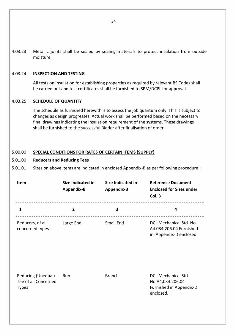
5.00.00 SPECIAL CONDITIONS FOR RATES OF CERTAIN ITEMS (SUPPLY)
5.01.00 Reducers and Reducing Tees
5.01.01 Sizes on above items are indicated in enclosed Appendix-B as per following procedure :
Item Size Indicated inAppendix-B
Size Indicated inAppendix-B
Reference DocumentEnclosed for Sizes underCol. 3
1 2 3 4
Reducers, of allconcerned types
Large End Small End DCL Mechanical Std. No.A4.034.206.04 Furnishedin Appendix-D enclosed
Reducing (Unequal)Tee of all ConcernedTypes
Run Branch DCL Mechanical Std.No.A4.034.206.04Furnished in Appendix-Denclosed.
35
5.01.02 The Tenderer shall quote for the above items which shall be exclusively based on thesizes indicated under Col.2 against above paragraph. For example, the prices of Reducersof a particular Specification and of Sizes, say, 200 mm NB x 150 mm NB, 200 mm NB x100 mm NB and 200 mm NB x 125 mm NB shall be same. Identical logic shall apply incase of Reducing Tees also.
5.01.03 For Concentric and Eccentric Reducers shall be same for a particular size andSpecification.
5.02.00 30o /45o/60o Elbows
Cost of Elbows of a particular Specification and size shall be same irrespective of aboveincluded angles. Consequently a total quantity for above included angles is indicated inAppendix-B against a particular Specification Code No. and Size.
6.00.00 CERTIFICATION OF CIB (IBR)
6.01.00 For SupplyWherever indicated for any item in any enclosed document certificate from aboveauthority of State of manufacture shall be furnished in prescribed Form (IIIA/IIIC)before dispatch of the concerned item. It shall be the total responsibility of the Vendorto get above certificates from the Concerned CIB.
6.02.00 For Erection ServicesWherever the requirement of Certification as per Indian Boiler Regulation (IBR) forerection work of any material is indicated the same shall be furnished in Form- IIIA / IIIC(as applicable for IBR).
6.02.01 In case the available CIB certificates for steam pipes are from outside of MadhyaPradesh, the final certification has to be obtained by the successful tenderer from CIBof Madhya Pradesh prior to erection.
7.00.00 CONDITIONS OF SUPPLY
7.01.00 Marking
7.01.01 In addition to the marking particulars required by the applicable standards (ASTM/IS)all items shall bear the corresponding "Specification Code Nos." used in thisSpecification. Method of marking shall be as specified in applicable ASTM/IS.
7.01.02 Wherever items are not as per any ASTM/IS Specification the same shall be markedwith the particulars and methods specified in relevant ASTM/IS specification for similaritems. However, in this case also, the same items shall be marked with the applicable"Specification Code Nos."

36
7.02.00 Surface ProtectionSurface of all black carbon steel items shall be protected against atmospheric corrosionby the application of a coat of Oil/Lacquer/Varnish.
7.03.00 Packing
7.03.01 All straight pipes shall be packed as per the relevant ASTM/IS standards. For pipes notspecified as per any ASTM/IS standard or where packaging specifications are notavailable the same shall be packed as per specifications of applicable ASTM standard.
7.03.02 All Pipe Fittings shall be properly and securely packed in wooden crates prior todelivery. All such crates shall be legibly marked with the following information.a) Name of the Purchaser (“Security Paper Mill”)b) Address of destination as advised in Purchase Order.c) Purchase Order No. and Date.d) Name of the Project as advised in the Purchase Order.e) Names of Pipe/Fittings packed andf) Specification Code Nos. of pipe Fittings.
8.00.00 DRAWINGS & DOCUMENTS THAT SHALL BEFURNISHED TO THE SUCCESSFUL TENDERER
In addition to the various standards and documents referred to above only thefollowing drawings & documents shall be furnished to the Contractor.A. Drawings & Documents.1. Flow Diagrams.2. Orthographic Drawings (Plans & Sections) showing fully dimensioned layout for
lines of sizes 50mm NB size shall have to be field routed & field supported.3. IBR approved drawings for lines within the purview of IBR.4. Piping Material Specifications.
B. Standards1. Instrumentation Standards2. Mechanical Standards (called out on the piping drawings).3. Support Standards.
C. Schedules1 Schedule of Special Materials2. Spring Hanger Schedule3. Flushing/Cleaning/blowing/pickling/passivating schedule.4. Schedule of local access platforms (Piping & valves)
D. OthersAny other document as may be decided by the Purchaser from time to time.

37
(Appendix – A)SITE AND MILL SERVICES DATA
A. PHYSICAL & CLIMATOLOGICAL DATA
1. Location
- Nearest Airport : Raja Bhoj Airport, Bhopal- Nearest Railhead : Hoshangabad- Nearest Sea Port : Mumbai
2. Altitude : 302 Meters above MSL
3. Ambient Air Temp.
- Maximum :- Minimum :- Average :
46.3º C3.3º C32.8º C
4. Mean Dry Bulb Temp. : 30.9º C
5. Mean Wet Bulb Temp. : 21.2º C
6. Relative Humidity
- Maximum : 91 %- Minimum : 19%
7. Rainfall
- Annual average :- Annual Maximum :
1225.9 mm2045.7 mm
8. Wind Velocity
- Mean :- Maximum :
0.8 m./sec2.1 m/sec
9. Earthquake zone : Seismic Zone III

38
SITE AND MILL SERVICES DATA (CONT’D.)
B. UTILITY SERVICES DATA
1. Mill water pressure at ground floor : 3.0 bar a
2. Mill air pressure : 6.0 bar a
3. Inst. Air pressure : 6.0 bar a
4. Process Steam Pressure & Temp.
- Medium Pressure - 2 : 8.5 bar g, 1810C
- Medium Pressure - 3 : 5.5 bar g. 1620C
- Low Pressure - 1 : 3.5 bar g, 1480C
- Low Pressure - 2 : 1.5 bar g, 1300C
5. Power Supply
• Primary Distribution Voltage : • 33 kV ±5%, 50 Hz ±3%, 3 Phase,3 Wire, Fault level : 31.5 KA for 3sec, Earthed through NGR
• Secondary Distribution Voltage : • 11 kV ±5%, 50 Hz ±3%, 3 Phase,3 Wire, Fault Level: 40 KA for 1sec,Earthed thru NGR
• 415 V ±10%, 50 Hz ±3%, 3 Phase,4 Wire, Effectively (Solidly)Earthed, Fault level:50 KA for 1 sec

39
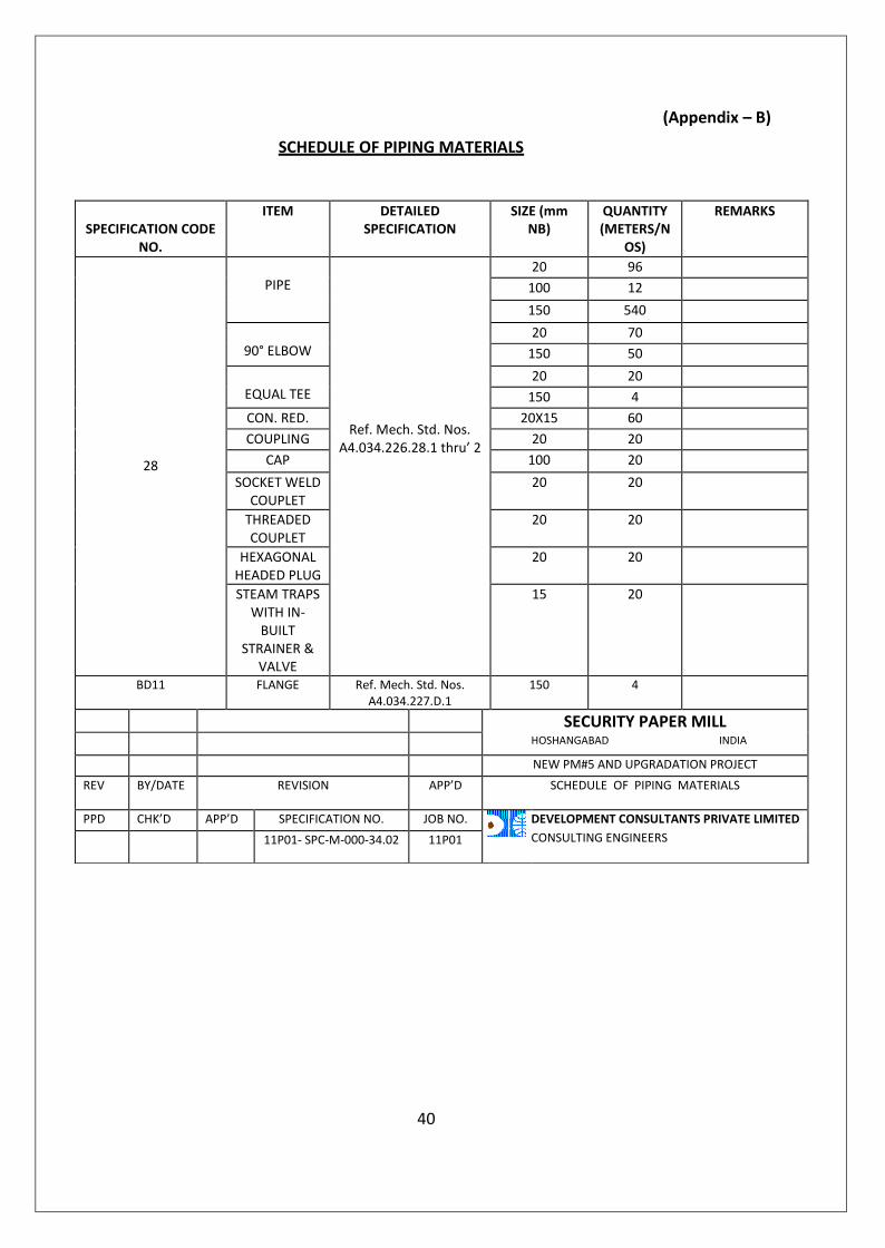
(Appendix – B)
SCHEDULE OF PIPING MATERIALS
40
SPECIFICATION CODENO.
ITEM DETAILEDSPECIFICATION
SIZE (mmNB)
QUANTITY(METERS/N
OS)
REMARKS
28
PIPE
Ref. Mech. Std. Nos.A4.034.226.28.1 thru’ 2
20 96100 12150 540
90° ELBOW20 70
150 50
EQUAL TEE20 20
150 4CON. RED. 20X15 60COUPLING 20 20
CAP 100 20SOCKET WELD
COUPLET20 20
THREADEDCOUPLET
20 20
HEXAGONALHEADED PLUG
20 20
STEAM TRAPSWITH IN-
BUILTSTRAINER &
VALVE
15 20
BD11 FLANGE Ref. Mech. Std. Nos.A4.034.227.D.1
150 4
SECURITY PAPER MILLHOSHANGABAD INDIA
NEW PM#5 AND UPGRADATION PROJECTREV BY/DATE REVISION APP’D SCHEDULE OF PIPING MATERIALS
PPD CHK’D APP’D SPECIFICATION NO. JOB NO. DEVELOPMENT CONSULTANTS PRIVATE LIMITEDCONSULTING ENGINEERS11P01- SPC-M-000-34.02 11P01
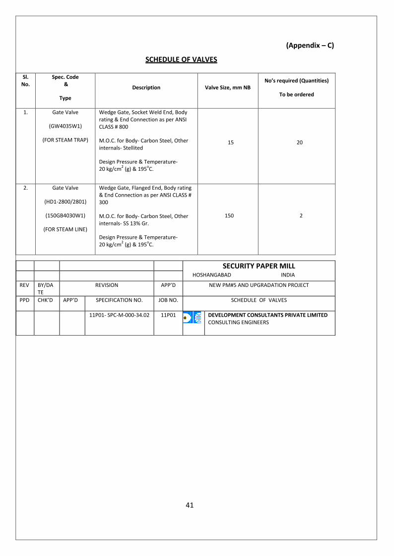
(Appendix – C)
SCHEDULE OF VALVES
Sl.No.
Spec. Code&
Type
Description Valve Size, mm NBNo’s required (Quantities)
To be ordered
1. Gate Valve
(GW4035W1)
(FOR STEAM TRAP)
Wedge Gate, Socket Weld End, Bodyrating & End Connection as per ANSICLASS # 800
M.O.C. for Body- Carbon Steel, Otherinternals- Stellited
Design Pressure & Temperature-20 kg/cm2 (g) & 195oC.
15 20
2. Gate Valve
(HD1-2800/2801)
(150GB4030W1)
(FOR STEAM LINE)
Wedge Gate, Flanged End, Body rating& End Connection as per ANSI CLASS #300
M.O.C. for Body- Carbon Steel, Otherinternals- SS 13% Gr.
Design Pressure & Temperature-20 kg/cm2 (g) & 195oC.
150 2
41
SECURITY PAPER MILLHOSHANGABAD INDIA
REV BY/DATE
REVISION APP’D NEW PM#5 AND UPGRADATION PROJECT
PPD CHK’D APP’D SPECIFICATION NO. JOB NO. SCHEDULE OF VALVES
11P01- SPC-M-000-34.02 11P01 DEVELOPMENT CONSULTANTS PRIVATE LIMITEDCONSULTING ENGINEERS

(Appendix – D)MECHANICAL STANDARDS
I N D E X
SL. NO. DWG. NO. DESCRIPTION SHEET NO.
1. A4.034.226.28.1 thru’2 Pipe Specification No. – 28 2 Sheets
2. A4.034.227.1 Flange Specification Code 1 Sheet
Numbering System
3. A4.034.227.2 -DO- 1 Sheet
4. A4.034.227.3 Installation of Flange Joints 1 Sheet
5. A4.034.227.A.1 thru’2 Flange Spec.-Carbon Steel Plate Type 2 Sheets
Slip on/Plate type Lap Joint
Backing/Blind Flange toClass 150
6. A4.034.227.B.1 -DO- 1 Sheet
7. A4.034.227.C.1 Flange Spec.-Carbon Steel 1 Sheet
Slip on/Welding Neck/
Blind Flange
8. A4.034.227.D.1 Flange Spec.-Carbon Steel(IBR) 1 Sheet
Slip on/Welding Neck/
Blind Flange
9. A4.034.227.E.1 Flange Spec.-G.I Screwed/ 1 Sheet
Blind Flange to Class 150
10. A4.034.228.1 Gasket Specification No. – G1 1 Sheet11. A4.034.228.2 Gasket Specification No. – G2 1 Sheet12. A4.034.228.12 Gasket Specification No. – G12 1 Sheet13. A4.034.229.1 Bolts Specification 1 Sheet
14. A4.034.201.7 Dimension for Socket weld Couplets 1 Sheet
15. A4.034.201.9 Details of Welding with Metal Arc 1 SheetProcess for IBR Services AttachmentOf Branch with Pad Type Reinforcement
42

SL. NO. DWG. NO. DESCRIPTION SHEET NO.
16. A4.034.201.14 Details of Welding with Metal Arc 1 SheetProcess for Class-I IBR Services AttachmentOf Branch without Reinforcement
17. A4.034.201.21 Details of Welding with Metal Arc 1 SheetProcess for Class-II IBR Services AttachmentOf Branch without Reinforcement.
18. A4.034.201.22 Details of Welding with Metal Arc 1 SheetProcess for Class-I IBR Services AttachmentOf Branch without Reinforcement.
19. A.034.203.02 Details of Socket welding attachment 1 SheetOf pipe socket weld End Component(Pipe Fittings or valves)
20. A4.034.203.03 Details of welding for IBR services, 1 SheetAttachment of Branch of Sizes 50NB& below, using socket welding half coupling
21. A.034.204.10 Steam Trap Assemblies Type-T1 2 Sheets
22. A.034.204.12 Drip Leg for Steam Lines 1 Sheet23. A4.034.206.04 Reduced Branching using a Tee 1 Sheet
(Equal or Reducing) and a Reducer
24. A4.034.226.38 Specification for Branch 1 SheetConnection on pipe linesFor low and moderatePressure temperatureServices.
25. A4.034.226.39 -DO- 1 Sheet
26. A4.034.225.3 Fabrication and installation 11 Sheetsof Carbon Steel, Alloy steel &Stainless Steel Piping System –General requirements
27. A4.034.225.4 Concreting, Brickwork , 2 SheetsPlastering & Excavation
28. A4.034.210.1 Pipe Support Notes 3 Sheets
43

SL. NO. DWG. NO. DESCRIPTION SHEET NO.
29. A4.001.001 Tension Band 1 Sheet
30. A4.001.003 Insulation for Elbow & Tees 1 Sheet
31. A4.001.004 Insulation for Flanges & Valves 1 Sheet
32. A4.001.013 Insulation Supports for Vertical Piping 1 Sheet
33. A4.034.230.07 Material Specifications-Piping & Valves 1 Sheet
44

1. PIPE
1.1 Material - Carbon Steel Black Pipes
1.2 Dimensions - Type E of ASTM A 53 Grade B (With Carbon Content = 0.25%)
1.3 Wall Thickness - Standard Weight.
1.4 End Preparation - Plain Ends.
2. FITTINGS
2.1 Material - ASTM A 234 Gr. WPB (with Carbon Content = 0.25%)
2.2 Dimensions
2.2.1 Elbows (45° and 90° only)
2.2.1.1 50 NB & below - Socket weld as per ANSI B 16.11. 3000 lb rating.
Elbows with any included angle other than above two (45° and90°) shall be fabricated (hot/cold bent with R = 5 x D) at site byPiping Erector from ‘Free Issue’ pipes.
2.2.1.2 65 NB and above - As per ANSI B16.9 Standard weight thick.
2.2.2 Reducers (Sizes indicated are for large ends only)
2.2.2.1 50 NB & below - Socket weld to ANSI B16.11. 3000 lb rating with(Only Concentric Following supplementary data :Reducers)
a) Bores of Sockets shall match nominal sizes of ends.b) Bore diameter ‘D’ shall be for small end size.c) Laying length ‘E’ shall be for large end size.
Above ‘D’ and ‘E’ dimensions correspond to ANSI B16.11 forsteel Socket welding Fittings.
MECHANICAL STANDARDPIPE SPECIFICATION
0 RFC – 1st Issue PSM May’12 NUMBER 28REV. DESCRIPTION APP’D DATE
PROJECT – SPM, NEW PM#5AND UPGRADATION PROJECT
DWG.NO. REV.DEVELOPMENT CONSULTANTS
PRIVATE LIMITEDCONSULTING ENGINEERS
APPROVED FOR THIS PROJECT:DCPL JOB NO. 11P01
A4.034.226.28.1 0
45

2.2.2.2 65 NB and above - As per ANSI B16.9 Standard Weight thick
2.2.3 Couplets - Type 1 as per DCPL Mech. Std. A4.034.201.7
2.2.4 All other Fittings
2.2.4.1 50 NB and below - Socket weld as per ANSI B16.11, 3000 lb rating.
2.2.4.2 65 NB and above - As per ANSI B16.9 Standard Weight thick
3. PIPE JOINTS
3.1 Erection Joints
3.1.1. 50 NB and below - Use Socket weld Couplings.
3.1.2 65 NB and above - Use Butt weld Joints
3.2 Maintenance Joints
Use Flanged joints for all sizes
4. BRANCH CONNECTION (EQUAL / REDUCING)
As per DCPL Mech. Std. No. A4.034.226.38 & 39
5. NOTES
5.1 This Specification is used for Steam service with following maximum service conditions.
Pressure Kg/cm2 Temperature °C Fluid Service Code
10.5 195 HD
MECHANICAL STANDARDPIPE SPECIFICATION
0 RFC – 1st Issue PSM May’12 NUMBER 28REV. DESCRIPTION APP’D DATE
PROJECT – SPM, NEW PM#5AND UPGRADATION PROJECT
DWG.NO. REV.DEVELOPMENT CONSULTANTS
PRIVATE LIMITEDCONSULTING ENGINEERS
APPROVED FOR THIS PROJECT:DCPL JOB NO. 11P01
A4.034.226.28.2 0
46

1.00.00 GENERAL
The Specification Code Number of any Flange shall consist of two digits and two letters. Thisalphanumeric combination shall be used to specify a Flange completely.
2.00.00 EXPLANATION
Above code numbering system is explained in following way :
First Part(a Letter)-------------
Second Part(a Letter)---------------
Third Part(a Digit)-------------
Fourth Part(a Digit)--------------
Designates theRated of theFlange as perANSI B 16.1/B 16.5 Standard
Designates theMaterial ofConstructionof the flange
Designates theMajorConstruction typeof the flange
Designates theFacing details ofthe Flange
3.00.00 SPECIFICATIONS AGAINST DESIGNATED LETTERS/DIGITS
First Part LetterDesignation--------------------
Second Part LetterDesignation-----------------------
Third Part DigitDesignation--------------------
Fourth Part DigitDesignation----------------------
A-Class 125*/150B-Class 250*/300C-Class 600D-E-Class 150F-Class 900
* For Cast Iron/SpheroidalGraphiteIron only
Carbon Steel tofollowing Spec.A- IS2062/ ASTMA216 Gr. WCBB-ASTMA181.CI.70C-ASTMA105/A216GR. WCBD-ASTMA105/A216Gr.WCBwith ‘C’ content
0.25%.E-Galvanised Iron
1-Slip-On withHub/Boss
2-Slip-On Platetype
3-Welding Neck-Std. Wt.**Thk.
4-Welding Neck-Sch.80 Thk. **
5-Welding Neck-Sch.120 Thk.**
6-Lap Joint Platetype
7-Lap joint withHub/Boss
8-Screwed9-Welding Neck
Thickness**To be specified0-Blind
** Thicknes ofMatching pipe atButtweld End.
1-Raised Face2-Flat Face3-Ring Type Joint4-Flat Face &
Undrilled
MECHANICAL STANDARDFLANGE SPECIFICATION CODE
0 RFC – 1st Issue PSM May’12 NUMBERING SYSTEMREV. DESCRIPTION APP’D DATEPROJECT – SPM, NEW PM#5AND UPGRADATION PROJECT
DWG.NO. REV.
APPROVED FOR THIS PROJECT:DCPL JOB NO. 11P01 A4.034.227.1 0
DEVELOPMENT CONSULTANTSPRIVATE LIMITED
CONSULTING ENGINEERS
47
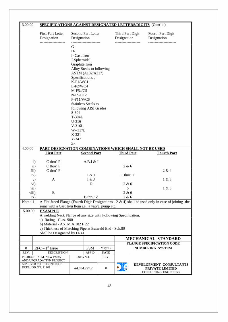
3.00.00 SPECIFICATIONS AGAINST DESIGNATED LETTERS/DIGITS (Cont’d.)
First Part LetterDesignation--------------------
Second Part LetterDesignation-----------------------
Third Part DigitDesignation--------------------
Fourth Part DigitDesignation----------------------
G-H-I- Cast IronJ-SpheroidalGraphite IronAlloy Steels to followingASTM (A182/A217)Specifications :K-F1/WC1L-F2/WC4M-F5a/C5N-F9/C12P-F11/WC6Stainless Steels tofollowing AISI GradesS-304T-304LU-316V-316LW--317LX-321Y-347Z-
4.00.00 PART DESIGNATION COMBINATIONS WHICH SHALL NOT BE USEDFirst Part Second Part Third Part Fourth Part
i) C thru’ F A.B.I & Jii) C thru’ F 2 & 6
iii) C thru’ F 2 & 4iv) I & J 1 thru’ 7v) A I & J 1 & 3
vi) D 2 & 6vii) 6 1 & 3
viii) B 2 & 6ix) B thru’ Z 2 & 6
Note :-1. A Flat-faced Flange (Fourth Digit Designations - 2 & 4) shall be used only in case of joining thesame with a Cast Iron Item i.e., a valve, pump etc.
5.00.00 EXAMPLEA welding Neck Flange of any size with Following Specification.a) Rating - Class 900b) Material - ASTM A 182 F 22c) Thickness of Matching Pipe at Butweld End - Sch.80Shall be Designated by FR41
MECHANICAL STANDARDFLANGE SPECIFICATION CODE
0 RFC – 1st Issue PSM May’12 NUMBERING SYSTEMREV. DESCRIPTION APP’D DATE
PROJECT – SPM, NEW PM#5AND UPGRADATION PROJECT
DWG.NO. REV.
APPROVED FOR THIS PROJECT:DCPL JOB NO. 11P01 A4.034.227.2 0
DEVELOPMENT CONSULTANTSPRIVATE LIMITED
CONSULTING ENGINEERS
48

2.00.0 MATERIAL
Material (Flange, Bolts, Nuts & Gaskets) shall be as specified in “PIPING MATERIALSPECIFICATION: for the Project.
2.00.0 INSTALLATION REQUIREMENT – GENERAL
Unless stated otherwise on the drawing, all flange holes shall straddle the center line of pipeMaximum allowable misalignment of flanges shall not exceed those shown in FIG. –1.
Flange faces shall not be concave. Convexity of the flange contact face width shall not exceed 1.6mm/100 mm width of flange face. Flanges with smooth finish or grooved for RTJ Convexity shall not exceed0.04 mm across the entire width of the raised face mating flanges.
MECHANICAL STANDARD
INSTALLATION OF FLANGE JOINTS0 RFC – 1st Issue PSM May’12REV.
DESCRIPTION APP’D DATE
PROJECT – SPM, NEW PM#5AND UPGRADATIONPROJECT
DWG.NO. REV.
APPROVED FOR THIS PROJECT:
DCPL JOB NO. 11P01A4.034.227.3 0 DEVELOPMENT CONSULTANTS
PRIVATE LIMITED
CONSULTING ENGINEERS49

1. Size : All Sizes
2. Materials :
2.1 50 NB and below :
Carbon steel plate to IS : 226 Gr. Fe 410-S (St 42-S) tested quality.
2.2 65 NB and above :
Carbon steel plates to IS : 2062 Gr. Fe 410-W (St 42 - W) tested quality or Carbon Steel plate asspecified in AWWA C 207-78.
3. Dimension :
3.1 Slip-on Plate Type Flanges
3.1.1 80 NB and below :
Same as those of Slip-on flange to ANSI B16.5, Class-150, including the knees except thatboss/bub is not required. Hence dimensions related to boss/hub are not applicable.
3.1.2 100 NB and above :
As per AWWA C207-78, Table-1, Class D including thickness, I.D. of flanges of 650 NB shall belarger by 6.4 mm than the O.D. of the connecting pipe which shall be as per ANSI B 36.10.
3.2 Lap Joint Plate Type Flanges :
3.2.1 80 NB and below :
Same as those of Lap Joint type flanges to ANSI B 16.5, Class - 150 including thickness exceptthat boss/hub is not required. Hence dimensions related to boss/hub are not applicable.
3.2.2 100 NB and above :
As per AWWA C 207-78 Table-1, Class - D including thickness I.D. of flanges shall be larger by6.4 mm than the O.D. of the connecting pipe which shall be as per ANSI B 36.19 Corner of ID onone face shall be filleted/45° chamfered with a radius of fillet / side of chamfered equal to 13mm.
MECHANICAL STANDARDFLANGE SPEC.-CARBON STEEL
0 RFC – 1st Issue PSM May’12 PLATE TYPE LAP JOINT BACKINGREV. DESCRIPTION APP’D DATE /BLIND FLANGE TO CLAS S 150
PROJECT – SPM, NEW PM#5AND UPGRADATION PROJECT
DWG.NO. REV.
APPROVED FOR THIS PROJECT:DCPL JOB NO. 11P01 A4.034.227.A.1 0
DEVELOPMENT CONSULTANTSPRIVATE LIMITED
CONSULTING ENGINEERS
50

3.3 Blind Flanges :
3.3.1 600 NB and below as per ANSI B 16.5 Class 150
3.3.2 650 NB above :
All dimensions except thickness shall be as per AWWA C207-78. Thickness shall be follows :
Size mm NB : 650 700 750 800 850 900 950 1000Thickness, mm 42.2 44.8 46.8 50.6 52.9 55.3 58.0 60.4
4. Method of Manufacture :
4.1 Slip-on Plate Type/Lap-Joint Plate Type Flanges / Blind Flanges :
Machined from plate to above specification. Each flange shall be machined out of single piece ofplate. Alternatively a maximum No. of four segment of plates may be used with butt weldedconstructional Weld fabrication shall be as per applicable paragraph of IS 2825 latest revision.All weld joints shall be fully radiographed. None of the bolt holes shall be placed on any weldjoint. All surfaces of flanges shall be finished machined.
5. Finish of Face
Matching face of slip-on plate type and blind flanges shall have serrations as per ANSI B16.5specification.
6. Call out codes
Letter Codes Digit Codes---------------- -------------------------------------------------------------------
1st Digit 2nd DigitAA 2-Slip-on plate type 1-Raised face
6-lap joint plate type 2-Flat face0-Blind 4-Flat face & undrilled
6.1 Normally Usable Call our Code :
AA21, AA01, AA62, AA22
For all other applicable call out order refer to Mech. Std. No. A4034.227.1
Note : 1 This flanges shall not be used beyond pressure of 10.5 kg/cm2 andtemperature of 93°C.
MECHANICAL STANDARDFLANGE SPEC.-CARBON STEEL
0 RFC – 1st Issue PSM May’12 PLATE TYPE LAP JOINT BACKINGREV. DESCRIPTION APP’D DATE /BLIND FLANGE TO CLAS S 150
PROJECT – SPM, NEW PM#5AND UPGRADATION PROJECT
DWG.NO. REV.
APPROVED FOR THIS PROJECT:DCPL JOB NO. 11P01 A4.034.227.A.2 0
DEVELOPMENT CONSULTANTSPRIVATE LIMITED
CONSULTING ENGINEERS
51

1. Size : All sizes
2. Type of Flanges : Slip-on, Welding - Neck, Lap-joint & Blind
3. Material : ASTM A 181 Class 70
4. Dimension : To ANSI B 16.5 for sizes 600 mm NB and below. Thickness at welding ends ofwelding neck flanges shall be as per call-out codes vide para no. 7 below.
5. Method of Manufacture : As per above material specification. Mating face, bore, welding endand seating surfaces for bolts/nuts on back of flanges shall be machine finished all bolt holes shallbe drilled.
6. Finish of Face : Mating face shall have serrations as per ANSI B16.5 (except Lap-Joint typeflanges).
7. Flange Call-out Spec. Codes
Letter Codes Digit Codes---------------------------------------- ----------------------------------------------------1st Letter 2nd Letter 1st Digit 2nd Digit
A-Class 150 B 1-Slip on with Hub/Boss 1-Raised FaceB-Class 300 3-WN Std. wt. thk. at ends
7-Lap Joint with Hub/Boss9-WN(thk. at ends to be 2-Flat Face
specified)0-Blind
7.1 Normally Usable Call our Code :
AB11, AB01, AB31, BB11, BB01, BB31, AB72, BB72
For all other applicable call-out codes refer to Mech. Std. No. A4034.227.1
MECHANICAL STANDARDFLANGE SPEC.-CARBON STEEL
0 RFC – 1st Issue PSM May’12 PLATE TYPE LAP JOINT BACKINGREV. DESCRIPTION APP’D DATE /BLIND FLANGE TO CLAS S 150
PROJECT – SPM, NEW PM#5AND UPGRADATION PROJECT
DWG.NO. REV.
APPROVED FOR THIS PROJECT:DCPL JOB NO. 11P01 A4.034.227.B.1 0
DEVELOPMENT CONSULTANTSPRIVATE LIMITED
CONSULTING ENGINEERS
52
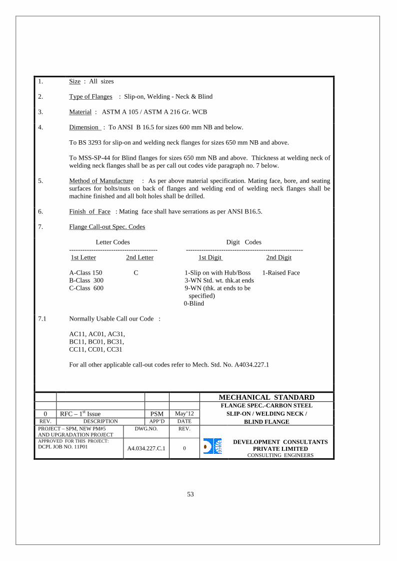
1. Size : All sizes
2. Type of Flanges : Slip-on, Welding - Neck & Blind
3. Material : ASTM A 105 / ASTM A 216 Gr. WCB
4. Dimension : To ANSI B 16.5 for sizes 600 mm NB and below.
To BS 3293 for slip-on and welding neck flanges for sizes 650 mm NB and above.
To MSS-SP-44 for Blind flanges for sizes 650 mm NB and above. Thickness at welding neck ofwelding neck flanges shall be as per call out codes vide paragraph no. 7 below.
5. Method of Manufacture : As per above material specification. Mating face, bore, and seatingsurfaces for bolts/nuts on back of flanges and welding end of welding neck flanges shall bemachine finished and all bolt holes shall be drilled.
6. Finish of Face : Mating face shall have serrations as per ANSI B16.5.
7. Flange Call-out Spec. Codes
Letter Codes Digit Codes---------------------------------------- -----------------------------------------------------1st Letter 2nd Letter 1st Digit 2nd Digit
A-Class 150 C 1-Slip on with Hub/Boss 1-Raised FaceB-Class 300 3-WN Std. wt. thk.at endsC-Class 600 9-WN (thk. at ends to be
specified)0-Blind
7.1 Normally Usable Call our Code :
AC11, AC01, AC31,BC11, BC01, BC31,CC11, CC01, CC31
For all other applicable call-out codes refer to Mech. Std. No. A4034.227.1
MECHANICAL STANDARDFLANGE SPEC.-CARBON STEEL
0 RFC – 1st Issue PSM May’12 SLIP-ON / WELDING NECK /REV. DESCRIPTION APP’D DATE BLIND FLANGE
PROJECT – SPM, NEW PM#5AND UPGRADATION PROJECT
DWG.NO. REV.
APPROVED FOR THIS PROJECT:DCPL JOB NO. 11P01 A4.034.227.C.1 0
DEVELOPMENT CONSULTANTSPRIVATE LIMITED
CONSULTING ENGINEERS
53
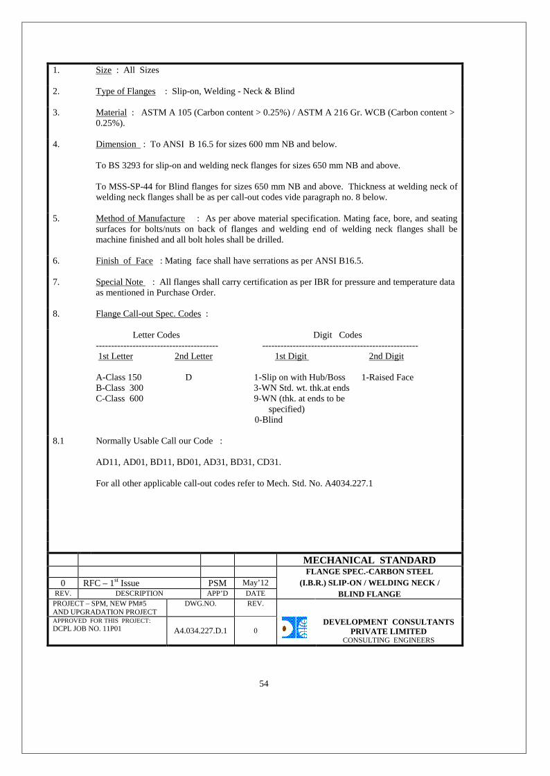
1. Size : All Sizes
2. Type of Flanges : Slip-on, Welding - Neck & Blind
3. Material : ASTM A 105 (Carbon content > 0.25%) / ASTM A 216 Gr. WCB (Carbon content >0.25%).
4. Dimension : To ANSI B 16.5 for sizes 600 mm NB and below.
To BS 3293 for slip-on and welding neck flanges for sizes 650 mm NB and above.
To MSS-SP-44 for Blind flanges for sizes 650 mm NB and above. Thickness at welding neck ofwelding neck flanges shall be as per call-out codes vide paragraph no. 8 below.
5. Method of Manufacture : As per above material specification. Mating face, bore, and seatingsurfaces for bolts/nuts on back of flanges and welding end of welding neck flanges shall bemachine finished and all bolt holes shall be drilled.
6. Finish of Face : Mating face shall have serrations as per ANSI B16.5.
7. Special Note : All flanges shall carry certification as per IBR for pressure and temperature dataas mentioned in Purchase Order.
8. Flange Call-out Spec. Codes :
Letter Codes Digit Codes---------------------------------------- ---------------------------------------------------1st Letter 2nd Letter 1st Digit 2nd Digit
A-Class 150 D 1-Slip on with Hub/Boss 1-Raised FaceB-Class 300 3-WN Std. wt. thk.at endsC-Class 600 9-WN (thk. at ends to be
specified)0-Blind
8.1 Normally Usable Call our Code :
AD11, AD01, BD11, BD01, AD31, BD31, CD31.
For all other applicable call-out codes refer to Mech. Std. No. A4034.227.1
MECHANICAL STANDARDFLANGE SPEC.-CARBON STEEL
0 RFC – 1st Issue PSM May’12 (I.B.R.) SLIP-ON / WELDING NECK /REV. DESCRIPTION APP’D DATE BLIND FLANGE
PROJECT – SPM, NEW PM#5AND UPGRADATION PROJECT
DWG.NO. REV.
APPROVED FOR THIS PROJECT:DCPL JOB NO. 11P01 A4.034.227.D.1 0
DEVELOPMENT CONSULTANTSPRIVATE LIMITED
CONSULTING ENGINEERS
54

1. Size : 150 NB and below.
2. Material : Hot dip galvanised carbon steel to IS : 226
3. Dimension : ANSI B 16.5, Class 150, Bore of Screwed Flange shall suit OD ofPipes to IS : 1239, Part I.
4. Method of Manufacture : Forging / Machining with machine cut threads followedby galvanising. If forged, all surfaces shall be machineprior to galvanising.
5. Finish of Face : Mating face shall have serrations.
6. Thread Standard : As per ANSI B16.5.
7. Flange Call-out Spec. Codes :
Letter Codes Digit Codes------------------- --------------------------------------------------1st Letter 1st Digit 2nd Digit
AE 8-Screwed 1-Raised Face0-Blind 2-Flat Face
For all other applicable call-out codes refer to Mech Std. No. A4034.227.1
Normally Usable Call our Code : AE81, AE01, AE82.
MECHANICAL STANDARDFLANGE SPEC.-G.I. SCREWED/
0 RFC – 1st Issue PSM May’12 BLIND FLANGE TO CLASS 150REV. DESCRIPTION APP’D DATE
PROJECT – SPM, NEW PM#5AND UPGRADATION PROJECT
DWG.NO. REV.
APPROVED FOR THIS PROJECT:DCPL JOB NO. 11P01 A4.034.227.E.1 0
DEVELOPMENT CONSULTANTSPRIVATE LIMITED
CONSULTING ENGINEERS
55

1. Size - All Sizes
2. Material - Neoprene or Nitrile Butadiene Rubber (Buna-N) as perASTM D 3185.
3. Dimensions - As per ANSI B 16.21, for bolting to Cast Iron items -B 16.1, 125 lb, Full-face type.
For all other locations - B 16.5, 150 lb, Flat Ring type.
4. Thickness - 1.6 mm
MECHANICAL STANDARD0 RFC – 1st Issue PSM May’12 GASKET SPECIFICATION
REV. DESCRIPTION APP’D. DATE NUMBER G1PROJECT – SPM, NEW PM#5AND UPGRADATION PROJECT
DWG.NO. REV.
APPROVED FOR THIS PROJECT:DCPL JOB NO. 11P01
A4.034.228.1 0
DEVELOPMENT CONSULTANTSPRIVATE LIMITED
CONSULTING ENGINEERS
56
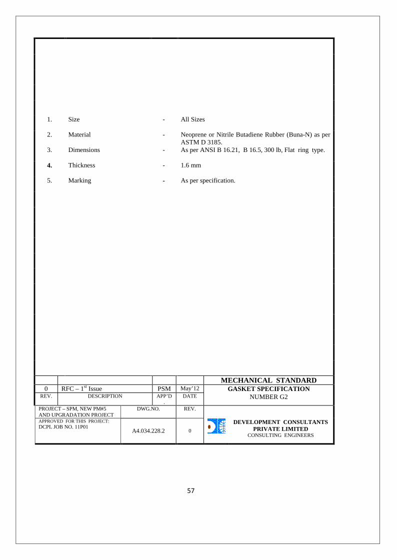
1. Size - All Sizes
2. Material - Neoprene or Nitrile Butadiene Rubber (Buna-N) as perASTM D 3185.
3. Dimensions - As per ANSI B 16.21, B 16.5, 300 lb, Flat ring type.
4. Thickness - 1.6 mm
5. Marking - As per specification.
MECHANICAL STANDARD0 RFC – 1st Issue PSM May’12 GASKET SPECIFICATION
REV. DESCRIPTION APP’D.
DATE NUMBER G2
PROJECT – SPM, NEW PM#5AND UPGRADATION PROJECT
DWG.NO. REV.
APPROVED FOR THIS PROJECT:DCPL JOB NO. 11P01
A4.034.228.2 0
DEVELOPMENT CONSULTANTSPRIVATE LIMITED
CONSULTING ENGINEERS
57
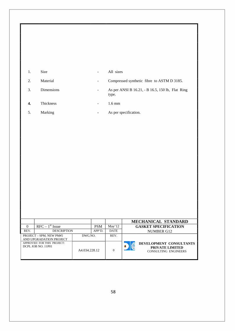
1. Size - All sizes
2. Material - Compressed synthetic fibre to ASTM D 3185.
3. Dimensions - As per ANSI B 16.21, - B 16.5, 150 lb, Flat Ringtype.
4. Thickness - 1.6 mm
5. Marking - As per specification.
MECHANICAL STANDARD0 RFC – 1st Issue PSM May’12 GASKET SPECIFICATION
REV. DESCRIPTION APP’D. DATE NUMBER G12PROJECT – SPM, NEW PM#5AND UPGRADATION PROJECT
DWG.NO. REV.
APPROVED FOR THIS PROJECT:DCPL JOB NO. 11P01
A4.034.228.12 0
DEVELOPMENT CONSULTANTSPRIVATE LIMITED
CONSULTING ENGINEERS
58

S P E C I F I C A T I O NSPEC. NO. B o l t s Heavy Hex. Nuts
Type Materials & Dimensions* Material & Dimension
B1 Machine Bolt ASTM A 307, Grade B ASTM A 563, Grade A
B2 Stud Bolt ASTM A 193, Grade B7 ASTM A 194, Grade 2H
B3 Machine Bolt ASTM A 193, Grade B7 ASTM A 194, Grade 2H
B4 Machine Bolt ASTM A 193, Grade B16 ASTM A 194, Grade 4
B5 Stud Bolt ASTM A 193, Grade B16 ASTM A 194, Grade 4
* Length of Bolts shall be as per ANSI B16.5 Standard forthe specified rating of concerned flanged joint.
MECHANICAL STANDARD0 RFC – 1st Issue PSM May’12 BOLT SPECIFICATION
REV. DESCRIPTION APP’D DATEPROJECT – SPM, NEW PM#5AND UPGRADATION PROJECT
DWG.NO. REV.
APPROVED FOR THIS PROJECT:DCPL JOB NO. 11P01
A4.034.229.1 0
DEVELOPMENT CONSULTANTSPRIVATE LIMITED
CONSULTING ENGINEERS
59
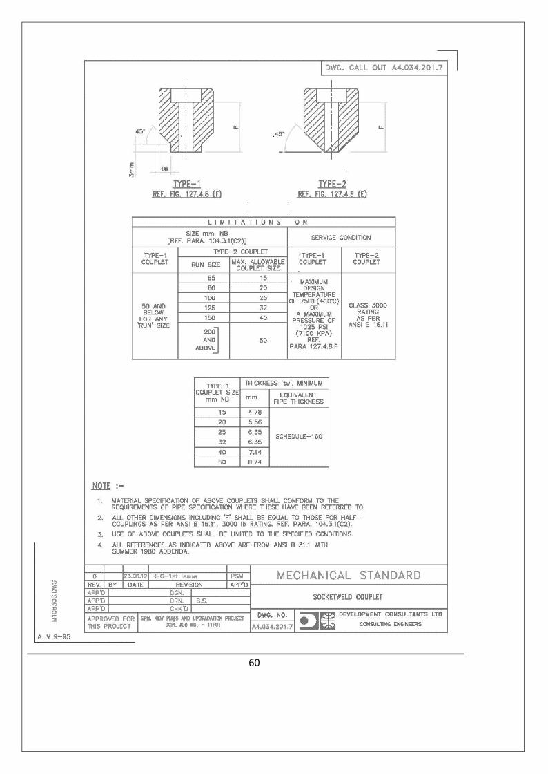
60
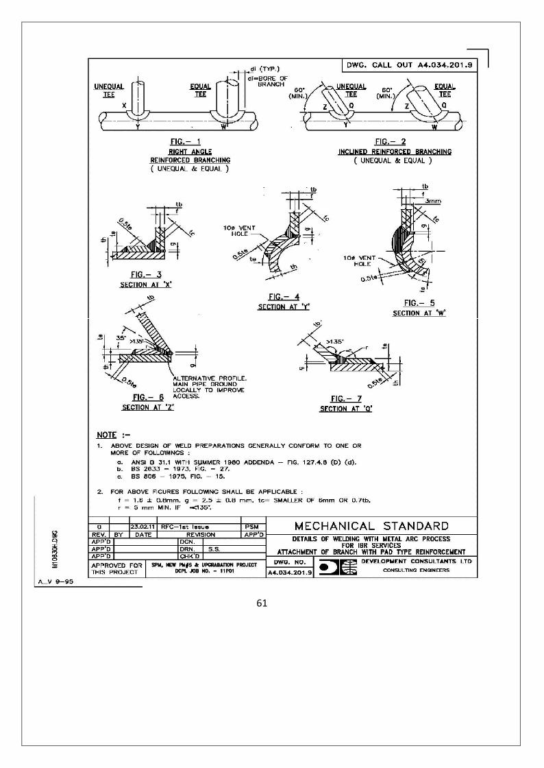
61
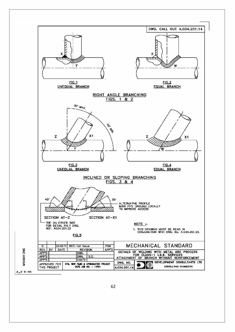
62
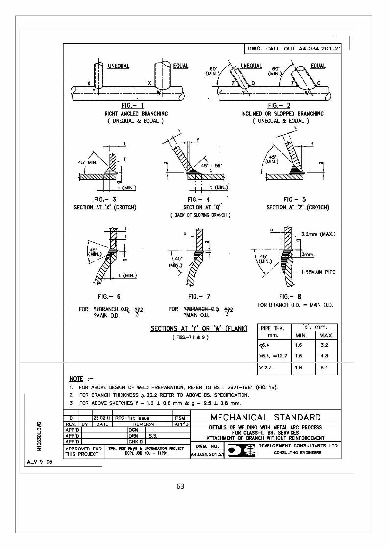
63
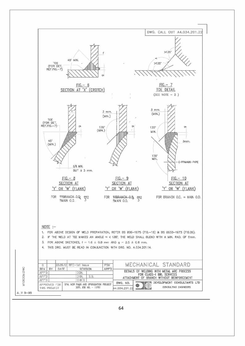
64

65
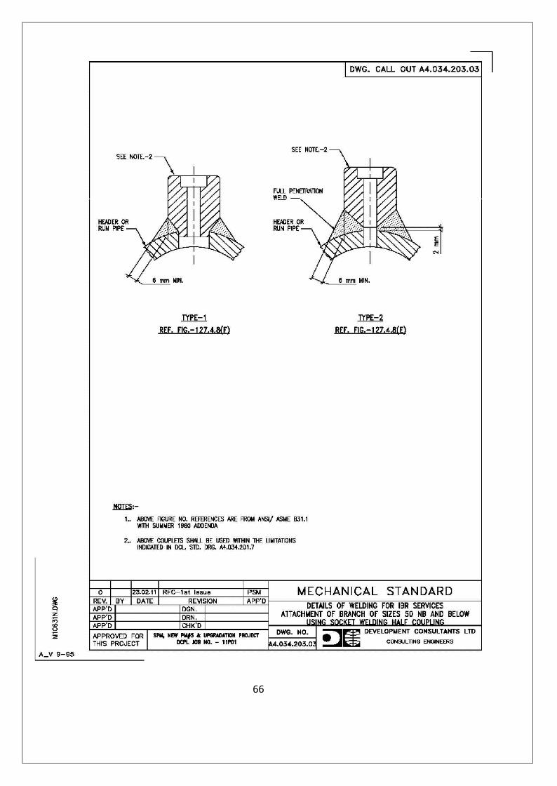
66

67
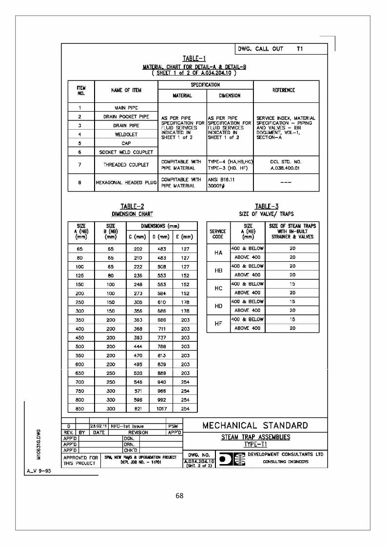
68
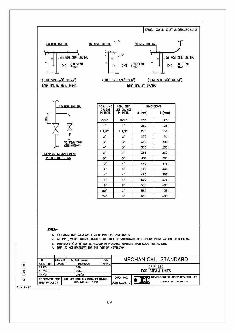
69
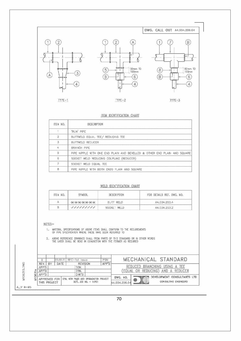
70

1. EQUAL BRANCHING
1.1 For `Run’ Sizes 50 NB and below
1.1.1 Method of Connection – Use Socket weld Equal Tee
1.1.2 Method of Welding Attachment – As per DCL Std. Drg. A.034.203.02
1.2 For `Run’ Sizes 65NB and above
1.2.1 Method of Connection - `Branch’ Pipes shall be directly welded on `Run’ Pipe. Requirement ofexternal Reinforcement to be welded on a particular Branch Connectionand Thickness thereof shall as per Schedule enclosed. Such externalreinforcement shall be of `Ring’ or `Pad’ type and out from `Run’/`Branch’ pipe and formed as required.
1.2.2 Method of Welding Attachmenta) For Branches Without Reinforcement -i) For Class I Services under IBR - As per DCL Stds. A4.034.201.14 & A4.034.201.22ii) For Class II Services under IBR- As per DCL Std.A4.034.201.21b) For Branches with Reinforcement - As per DCL Std. Drg.A4.034.201.9
2. REDUCED OR UNEQUAL BRANCHES2.1 For `Run’ Sizes 50NB and below
2.1.1 Method of Connection - Shall be by Use of following :
a) Socket weld Equal Tee
b) One No. Pipe Nipple with both Ends Plain and Square
and c) One No. Socket weld Reducing Coupling.
2.1.2 Method of Welding - As per DCL Std. Drg. A4.034.206.04, Type -3 .Attachment
2.2 For `Run’ Sizes 65NB and above
2.2.1 For `Branch’ Sizes 50NB and below
Contd. To Dwg. No. A4.034.226.39
MECHANICAL STANDARDSPECIFICATION FOR BRANCH CONNECTION ON
0 RFC – 1st Issue PSM May’12 PIPELINES FOR LOW & MODERATE PRESSURE
REV. DESCRIPTION APP’D DATE TEMPERATURE SERVICESPROJECT – SPM, NEW PM#5AND UPGRADATION PROJECT
DWG.NO. REV.
APPROVED FOR THIS PROJECT:DCPL JOB NO. 11P01
A4.034.226.38 0 DEVELOPMENT CONSULTANTSPRIVATE LIMITED
CONSULTING ENGINEERS
71

Contd. From Dwg. No. A4.034.226.38
2.2.1.1 Method of Connection – Use Socket weld Couplets.
2.2.1.2 Method of Welding - As per DCL Std. Drg.Attachment A4.034.203.03 (Type – 1)
2.2.2 For `Branch Sizes’ 65NB and above
2.2.2.1 Method of Connection – Same as against Para 1.2.1 above.
Method of WeldingAttachment - Same as against Para 1.2.2 above.
Notes : 1) All Items Required for Making a Branch Connection as per this Standard shall Conformto the Specification Stipulated in Pipe Specification Standard where this standard hasbeen Referred to .
2) All Standards mentioned in this Standard shall form part/s of this Standard. In otherwords this Standard shall be used in Conjunction with all other Standards Referred herein.
MECHANICAL STANDARDSPECIFICATION FOR BRANCH CONNECTION ON
0 RFC – 1st Issue PSM May’12 PIPELINES FOR LOW & MODERATE PRESSURE
REV. DESCRIPTION APP’D DATE TEMPERATURE SERVICESPROJECT – SPM, NEW PM#5AND UPGRADATION PROJECT
DWG.NO. REV. DEVELOPMENT CONSULTANTSPRIVATE LIMITED
CONSULTING ENGINEERSAPPROVED FOR THIS PROJECT:DCPL JOB NO. 11P01
A4.034.226.39 0
72
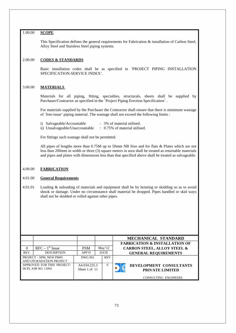
1.00.00 SCOPE
This Specification defines the general requirements for Fabrication & installation of Carbon Steel,Alloy Steel and Stainless Steel piping systems.
2.00.00 CODES & STANDARDS
Basic installation codes shall be as specified in `PROJECT PIPING INSTALLATIONSPECIFICATION-SERVICE INDEX’.
3.00.00 MATERIALS
Materials for all piping, fitting, specialties, structurals, sheets shall be supplied byPurchaser/Contractor as specified in the `Project Piping Erection Specification’ .
For materials supplied by the Purchaser the Contractor shall ensure that there is minimum wastageof `free-issue’ piping material. The wastage shall not exceed the following limits :
i) Salvageable/Accountable : 3% of material utilised.ii) Unsalvageable/Unaccountable : 0.75% of material utilised.
For fittings such wastage shall not be permitted.
All pipes of lengths more than 0.75M up to 50mm NB Size and for flats & Plates which are notless than 200mm in width or three (3) square meters in area shall be treated as returnable materialsand pipes and plates with dimensions less than that specified above shall be treated as salvageable.
4.00.00 FABRICATION
4.01.00 General Requirements
4.01.01 Loading & unloading of materials and equipment shall be by hoisting or skidding so as to avoidshook or damage. Under no circumstance shall material be dropped. Pipes handled or skid waysshall not be skidded or rolled against other pipes.
MECHANICAL STANDARDFABRICATION & INSTALLATION OF
0 RFC – 1st Issue PSM May’12 CARBON STEEL, ALLOY STEEL &REV. DESCRIPTION APP’D DATE GENERAL REQUIREMENTSPROJECT – SPM, NEW PM#5AND UPGRADATION PROJECT
DWG.NO. REV.
APPROVED FOR THIS PROJECT:DCPL JOB NO. 11P01
A4.034.225.3Sheet 1 of 11
0 DEVELOPMENT CONSULTANTSPRIVATE LIMITED
CONSULTING ENGINEERS
73

4.01.02 Sections of pipes shall not be welded together for lengths below 3M (2.5M for large diameter C.S.fabrication and rolled & welded S.S. pipes). Number of lengths shall be kept to a minimum forlonger lengths.
4.01.03 Materials which have been damaged or found to have defects shall not be used in fabricationexcept that minor surface marks may be dressed provided that the nominal wall or minimum wallthickness is not encroached after considering the manufacturing tolerance.
4.01.04 Unless stated otherwise on the drawings all flanges bolt holes shall straddle the centerlines of thepipes.
4.01.05 Longitudinal seams in seam-welded pipe shall be located so as to clear opening and externalattachments wherever possible. Longitudinal seams to adjoining courses shall preferably be at180º but a minimum between seams of 150mm measured around pipe circumference isacceptable.
4.02.02 Fabrication & Installation Tolerances
4.02.01 In addition to tolerance specified in the applicable `Installation Code’ (See project pipinginstallation specification-service index) the following also applies.
4.02.02 All linear dimensions involved in the relative position of branches bosses, flanged ends, flowinstrument tapings and change in directions to each other shall be maintained within ± 3 mm.
4.02.03 All angular dimensions of bends and branches shall be maintained within ± ¼ degree.
4.02.04 Mechanical Standard Dwg. No. A4.034.227.3 is enclosed herewith which indicates the allowablemisalignment of flanges and branch welding ends.
MECHANICAL STANDARDFABRICATION & INSTALLATION OF
0 RFC – 1st Issue PSM May’12 CARBON STEEL, ALLOY STEEL &REV. DESCRIPTION APP’D DATE GENERAL REQUIREMENTSPROJECT – SPM, NEW PM#5AND UPGRADATION PROJECT
DWG.NO. REV.
APPROVED FOR THIS PROJECT:DCPL JOB NO. 11P01
A4.034.225.3Sheet 2 of 11
0 DEVELOPMENT CONSULTANTSPRIVATE LIMITED
CONSULTING ENGINEERS
74
4.02.05 Pipes with a thickness less than 6mm shall not have internal misalignment of pipe wall exceeding 25percent of pipe wall thickness. Pipe with a thickness of 6mm and above shall not preferably haveinternal misalignment of pipe wall exceeding 1.5mm. Where the internal misalignment of pipe wallexceeds 1.5mm the component with the wall extending internally shall be internally trimmed.
4.02.06 For items of tolerance which are not covered by this Specification PFI-ES-3 (Pipe FabricationInstitute-USA) shall be applicable
4.02.07 Regarding any requirement of load bearing structural attachments such as tolerance etc. which arenot shown in Purchaser’s Drawing PFI-ES-26 (Pipe Fabrication Institute-USA) shall be applicable
4.03.00 Fit – Up
Pipes shall be properly aligned by Jigs or clamps as required in order to preclude extraneous load& minimize strain during tackling.
5.01.0 Threading
4.04.01 All threading shall be carried out after bending, forging or after heat treatment but where this is notpossible suitable thread protection must be provided.
4.04.02 Threads shall be concentric with the pipe and rough, wavy, sheared or improperly made threads ofany description shall be out from the pipe and new threads to be made to the satisfaction of thePurchaser.
4.04.03 Threaded joints which are to be seal welded shall be made up dry (without thread compound ortape).
5.00.00 WELDING
5.01.0 Welding Process
All piping shall be welded either by using any one of the following methods or a combination ofthese:
MECHANICAL STANDARDFABRICATION & INSTALLATION OF
0 RFC – 1st Issue PSM May’12 CARBON STEEL, ALLOY STEEL &REV. DESCRIPTION APP’D DATE GENERAL REQUIREMENTSPROJECT – SPM, NEW PM#5AND UPGRADATION PROJECT
DWG.NO. REV. DEVELOPMENT CONSULTANTS
PRIVATE LIMITED
CONSULTING ENGINEERS
APPROVED FOR THIS PROJECT:DCPL JOB NO. 11P01
A4.034.225.3Sheet 3 of 11
0
75
[Type a quote from the document or thesummary of an interesting point. Youcan position the text box anywhere inthe document. Use the Drawing Toolstab to change the formatting of the pullquote text box.]
Manual Metallic Arc : MMATungsten Inert Gas : TIGSubmerged Arc Welding : SMAWPlasma Arc Welding : -
For specific requirements, if any, refer to “PROJECT PIPING INSTALLATIONSPECIFICATION SERVICE INDEX”.
5.02.00 Welding Procedure
5.02.01 S.S. Pipes :
Some of the parameters have been defined in the following documents :
a) Dwg. No. A 034.225.1 Sheets 1 thru’ 7 – Clause Nos. 2.01.00, 20.02.00, 4.00.00,6.00.00, 10.00.00 thru’ 11.04.02.
5.02.02 DCPL Mech./IN-2/R-0
Other parameters shall be established through “Welding Procedure Specification” (As per SectionIX. ASME Boiler & Pressure Vessel Code). No work shall start until the procedure qualification testfor the particular type of welding have been inspected & accepted by “Purchaser”.
5.03.01 C.S. Pipes :
Some of the parameters have been defined in the “PROJECT PIPING INSTALLATIONSPECIFICATION – SERVICE INDEX”.
Other parameters shall be established through “Welding Procedure Specification”. No work shallstart until the procedure qualification test for particular type of welding have been inspected &accepted by the Purchaser.
5.03.00 General Requirements
5.03.01 No welding shall be done on surfaces which are wet. Surfaces to be welded shall be free from paint,rust, oil, grease, dust or any other contamination. Clothes used for cleaning shall be lint free.
MECHANICAL STANDARDFABRICATION & INSTALLATION OF
0 RFC – 1st Issue PSM May’12 CARBON STEEL, ALLOY STEEL &REV. DESCRIPTION APP’D DATE GENERAL REQUIREMENTSPROJECT – SPM, NEW PM#5AND UPGRADATION PROJECT
DWG.NO. REV. DEVELOPMENT CONSULTANTS
PRIVATE LIMITED
CONSULTING ENGINEERS
APPROVED FOR THIS PROJECT:DCPL JOB NO. 11P01
A4.034.225.3Sheet 4 of 11
0
76
Welds shall be cleaned between passes to remove all traces of slag and flux before successive bids orlayers are deposited. Completed weldments shall be cleaned to the same extent. The erators at thestarting and stopping points of each individual bead shall be carefully examined and any defectsshall be removed by grinding. Grinding wheels, wire brushes, chisels, etc. for use on stainless steelshall not be used on any other materials. The grinding wheels should be iron free and wire brushesshould be austenitic stainless steel to avoid iron contamination of the stainless steel surfaces.
Pining shall not be permitted.
The welding technique and arc manipulation shall be controlled to ensure the following:
a) Full Penetration.b) Full Fusion into the base metal without undercutting along the sides of the weld.c) Full fusion into the preceding bead or layer.d) Uniformity of surface in both single run passes and beaded layers.e) Floating all slag, oxide and gases to the surface behind the advancing arc.f) Delay in electrode travel until base metal fusion at the starting point is assured
and until the erector is well filled at the completion of the weld.
Haphazard striking of the electrode on the base metal in establishing the arc shall not be permitted.The arc should be struck either in the joint where the metal surface will be fused into the weld or ona starting tab. Starting tabs shall be of the same material or a material compatible with the base metalbeing welded.
When welding stainless steel stringer’s bead technique shall be used with slight oscillation ifnecessary to avoid entrapped slag and to minimize the number of beads needed to fill a joint.Because of higher co-efficient of expansion and lower thermal conductivity of stainless steel, it isnecessary to take precautions to reduce distortion, Skip welding, back step welding or effective tackwelding before-hand are the usual methods. Control of interpass temperature should also be used.
MECHANICAL STANDARDFABRICATION & INSTALLATION OF
0 RFC – 1st Issue PSM May’12 CARBON STEEL, ALLOY STEEL &REV. DESCRIPTION APP’D DATE GENERAL REQUIREMENTSPROJECT – SPM, NEW PM#5AND UPGRADATION PROJECT
DWG.NO. REV.
APPROVED FOR THIS PROJECT:DCPL JOB NO. 11P01
A4.034.225.3Sheet 5 of 11
0 DEVELOPMENT CONSULTANTSPRIVATE LIMITED
CONSULTING ENGINEERS
77
Vertical welds shall be made in an upward direction. On pipes ever 300mm in diameter weldingshall be done whenever possible by two welders working simultaneously on both sides of the pipe.
5.03.02 Temporary attachments such as may be required to retain fit up for welding shall be of materialcompatible with the material to which it is attached.
Removal of temporary attachments may be done by grinding, chipping, sawing or in the case ofheavy weldments by arc gauging or flame cutting. . The attachment is to be reduced to a very smallcross section and then the attachment “knocked off” when arc or flame gauging is used at least 1/8inch of metal shall be left on the pipe surface which will then be removed by grinding.
All tack welds shall either be removed completely with progress of welding or shall be properlyprepared by grinding or filling their stopping and starting ends so that they may be satisfactorilyincorporated into the final weld.
End preparation for welding shall be in accordance with the code of application/drgs for the specificproject. However, a set of drgs. is enclosed with this specification which shall be referred to inabsence of any such stipulated requirements for a project.
All butt welded joints shall have their end preparations formed by machining. Checking should bedone with profile gauges. Flame cutting may be used on Carbon Steel material to form the endpreparation, provided the cut edge is ground back at least 1/6 inch below the deepest indentation.
5.03.03 Finish of the completed weld shall be as required by the applicable codes/standards.
Intermediate passes or layers shall be of a flat to slightly concave contour, fully fused to the jointside-walls and each other, with sufficient overlap to prevent excess ridges and valleys and tominimise inclusions.
Final contour shall be slightly convex with complete coalescence at the weld tees to base metal.Where no Code/Standards requirements is given for the project, the reinforcement shall not exceed5.0mm for thickness up to 25.0mm and 6.0mm for thickness 25-50mm and undercut shall notexceed 1.0 mm.
MECHANICAL STANDARDFABRICATION & INSTALLATION OF
0 RFC – 1st Issue PSM May’12 CARBON STEEL, ALLOY STEEL &REV. DESCRIPTION APP’D DATE GENERAL REQUIREMENTSPROJECT – SPM, NEW PM#5AND UPGRADATION PROJECT
DWG.NO. REV.
APPROVED FOR THIS PROJECT:DCPL JOB NO. 11P01
A4.034.225.3Sheet 6 of 11
0 DEVELOPMENT CONSULTANTSPRIVATE LIMITED
CONSULTING ENGINEERS
78

Argon gas used in TIG welding for shielding and purging shall be at least 99.95% pure.
When purging 300 series stainless steel dry Nitrogen conforming to IS 1747 may be used althoughthe use of Argon is preferred.
Purging at a flow rate of approximately 10 cu.ft./hr. subjected to a maximum of 50 cu.ft./hr.depending on the diameter of the pipe until 6 times the volume of the section of piping between thedams has been replaced is usually adequate. In no case should the initial purge be for less than 10minutes. After initial purging is completed, the flow of backing gas during welding should bereduced to a point where a small positive pressure prevails. All these flow rates should beestablished at the procedure qualification stage.
Gas backing (purging) is not required on socket type welded joints provided it is ensured thatoxidation does not take place in case of stainless steel.
5.03.05 As far as practicable the heat treatment of pipe sections or sub-assemblies should be done in a closedfurnaces.
The furnace provided should be capable of accommodating the entire sub-assembly. In case wherethe pipe section or sub-assembly are too large to be accommodated in one heat, the parts may beheated in more than one heat if the overlap of the heated portions is at least 5 ft. When thisprocedure is used, the cooling rate of the portion outside the furnace shall be controlled by insulationto provide a gradually diminishing temperature outward from the heated portion. The cross sectionwhere the part projects from the furnace shall not intersect a nozzle or other structural discontinuity.
When induction or resistance heating methods are used, the width of the heated band on each side ofthe greatest width of the finished weld, including welded branch connections, shall not be less thantwice the wall thickness of the thicker component. Uniform temperature around the entirecircumference of the piping shall be ensured.The use of gas torches and gas rings shall be restricted to preheating operations not exceeding250º F.
MECHANICAL STANDARDFABRICATION & INSTALLATION OF
0 RFC – 1st Issue PSM May’12 CARBON STEEL, ALLOY STEEL &REV. DESCRIPTION APP’D DATE GENERAL REQUIREMENTSPROJECT – SPM, NEW PM#5AND UPGRADATION PROJECT
DWG.NO. REV.
APPROVED FOR THIS PROJECT:DCPL JOB NO. 11P01
A4.034.225.3Sheet 7 of 11
0 DEVELOPMENT CONSULTANTSPRIVATE LIMITED
CONSULTING ENGINEERS
79

6.00.00 CLEANING
For cleaning requirements refer to Flushing/Cleaning /Blowings / Pickling/Passivating schedule.
7.00.00 INSPECTION & TESTING
Installed pipe lines/prefabricated spools shall be tested for -
a) Compliances with drawings & other related documents.b) Soundness of Production welds.c) Leak tightness.
7.01.00 Rights of Inspection
The Inspecting Authority shall have the right to inspect all welds by non-destructivemethods or by removing welds and subjecting them to mechanical tests. Theinspection may be made during the welding or after the welding has been completed.Inspectors shall have right to review all the certificates and records pertaining to theInspection requirement including certified qualifications for welder’s performanceand weld-procedure qualification test.
7.02.00 Methods of Inspection
Inspection shall be carried out generally in accordance with applicable parts of Section-I, V and VIIIof ASME Boiler and Pressure Vessel Code. API-1104, ANSI B 31.1 and IS: 822-1970.
Non-destructive testing may consist of radiographic inspection or any other methods specified bythe Purchaser. (Refer to “PROJECT PIPING INSTALLATION SPECIFICATION - SERVICEINDEX”) The welds may also be examined be destructive means and the specimens in such caseshall be prepared and meet the requirements of Section IX of ASME - Boiler and Pressure VesselCode.
7.03.00 Hydrostatic Testing
Hydrostatic testing for leak-tightness shall be carried out as per the applicable “Installation Code”and PFI-ES-4 (Pipe Fabrication Institute -USA) Hydrostat measures shall be as specified in the“Line List”
MECHANICAL STANDARDFABRICATION & INSTALLATION OF
0 RFC – 1st Issue PSM May’12 CARBON STEEL, ALLOY STEEL &REV. DESCRIPTION APP’D DATE GENERAL REQUIREMENTSPROJECT – SPM, NEW PM#5AND UPGRADATION PROJECT
DWG.NO. REV.
APPROVED FOR THIS PROJECT:DCPL JOB NO. 11P01
A4.034.225.3Sheet 8 of 11
0 DEVELOPMENT CONSULTANTSPRIVATE LIMITED
CONSULTING ENGINEERS
80

7.04.00 Non-destructive Examination
The types and extent of non-destructive examinations shall be as specified in the “PROJECT PIPINGINSTALLATION SPECIFICATION-SERVICE INDEX”. Welds not requiring non-destructive testing(other than visual) by the design specifications-will be judged -acceptable if they pass the leak test .(See Clause 7.03.00).
7.04.01 Visual Examination :
Visual examination consists of observation of whatever portions of a component or weld are exposedto such observation, either before, during or after completion of welding.
A. Acceptance Standards. The following indications are unacceptable :
A1. Cracks - external surface.
A2. Under on surface which is greater than 1/32 (1.00 mm) inch deep.
A3. Weld-reinforcement greater than specified in Table 127.4.2 of ANSI B 31.1
A4. Lack of fusion on surface.
A5. Incomplete penetration (applies only when inside surfaces is readily accessible).
7.04.02 Magnetic Particle Examination :
Whenever required by design specification, magnetic particles examination shall be performed inaccordance with the methods of Article-7, Section-V of the ASME Boiler and Pressure Vessel Code.
A. Acceptable Standards. The following relevant indications are unacceptable :A1. Any cracks or linear indications.A2. Rounded indications with dimensions greater than 3/16 inch (5.00 mm).A3. Four or more rounded indications in a line separated by 1/16 inch (2.0 mm) or
less edge to edge.
MECHANICAL STANDARDFABRICATION & INSTALLATION OF
0 RFC – 1st Issue PSM May’12 CARBON STEEL, ALLOY STEEL &REV. DESCRIPTION APP’D DATE GENERAL REQUIREMENTSPROJECT – SPM, NEW PM#5AND UPGRADATION PROJECT
DWG.NO. REV.
APPROVED FOR THIS PROJECT:DCPL JOB NO. 11P01
A4.034.225.3Sheet 9 of 11
0 DEVELOPMENT CONSULTANTSPRIVATE LIMITED
CONSULTING ENGINEERS
81
A4. Ten or more rounded indications in any 6 square inches or surface with a majordimension not to exceed 6 inches the area taken in the most favourable locationrelative to the indications being evaluated.
7.04.03 Liquid Penetrant Examination
Whenever required by the design specification, liquid penetrant examination shall be performed inaccordance with the methods of Article-6, Section-V of the ASME- Boiler and Pressure Vessel Code.
A. Acceptance Standards. Indications where major dimensions are greater than1/16 inch (2.0 mm) shall be considered relevant. The following relevant indications areunacceptable.
A1 Any cracks or linear indications.A2 Rounded indications with dimensions greater than 3/16th inch (5.00mm).A3 Four or more rounded indications in a line separated by 1/16 inch (2.0mm)
or less edge to edge.A4 Ten or more rounded indications in any 6 square inches of surface with the
major dimension of this area taken in the most unfavourable location relative to theindications being evaluated.
7.05.00 Radiography
Wherever required by the design specification, radiography examination shall be performed inaccordance with the Article – 3, of Section – V of the ASME Boiler and Pressure Code.
A. Acceptance Standards. Welds that are shown of radiography to have any of the followingtypes of discontinuities are unacceptable.
A1. Any type of crack or zone of incomplete fusion or penetration .A2. Any other elongated indication which has length greater than :A2.1 ¼ inch (6.0 mm) for `t’ up to ¾ inch (19.0 mm) inclusive.A2.2 1/3t for t from¾ inch (19.0 mm) to 2¼ inch (57.0 mm) inclusiveA2.3 ¾ inch (19.0 mm) for t ever 2¼ inch (57.0 mm) where t is the thickness of
the thinner portion of the weld.
MECHANICAL STANDARDFABRICATION & INSTALLATION OF
0 RFC – 1st Issue PSM May’12 CARBON STEEL, ALLOY STEEL &REV. DESCRIPTION APP’D DATE GENERAL REQUIREMENTSPROJECT – SPM, NEW PM#5AND UPGRADATION PROJECT
DWG.NO. REV.
APPROVED FOR THIS PROJECT:DCPL JOB NO. 11P01
A4.034.225.3Sheet 10 of 11
0 DEVELOPMENT CONSULTANTSPRIVATE LIMITED
CONSULTING ENGINEERS
82
A3 Any group of indications in line that have an aggregate length greater than tin a length of 12 t except where the distance between the successive indications exceeds 6L,where L is the longest indication in the group.
A4 Porosity in excess of that shown as acceptable in Appendix-A 250 of Section-1 of ASMEBoiler and Pressure Vessel Code.
7.06.00 Ultrasonic Examination
Whenever required by design specification, ultrasonic examination shall be performed in accordancewith Article 5 of Section V of the ASME Boiler and Pressure Vessel Code.
7.06.01 Acceptance of Rejection Standards –
Linear type discontinuities are unacceptable if the amplitude exceeds the reference level anddiscontinuities have lengths which exceeds the following :
¼ inch (6.0 mm) for t up to ¾ inch (19.0 mm)1/3 t (8.0 mm) for t from¾ inch (19.0 mm) to 2¼ inch (57.0 mm)¾ inch (19.0 mm) for t ever 2¼ inch (57.0)
where t is the thickness of the thinner portion of the weld.
8.00.0 MARKING
Pipe lines & sub-assemblies may be marked in accordance with the line designation on the flowdiagram & match marked. The materials shall be marked by any method such as die-stampingetching, painting, etc. that will not result in any harmful contamination or sharp discontinuities andwhich will identify the material until the system is completely installed.
MECHANICAL STANDARDFABRICATION & INSTALLATION OF
0 RFC – 1st Issue PSM May’12 CARBON STEEL, ALLOY STEEL &REV. DESCRIPTION APP’D DATE GENERAL REQUIREMENTSPROJECT – SPM, NEW PM#5AND UPGRADATION PROJECT
DWG.NO. REV.
APPROVED FOR THIS PROJECT:DCPL JOB NO. 11P01
A4.034.225.3Sheet 11 of 11
0 DEVELOPMENT CONSULTANTSPRIVATE LIMITED
CONSULTING ENGINEERS
83

CONCRETING, BRICKWORK, PLASTERING & EXCAVATION
Concreting, Brickwork, Plastering & Excavation shall conform to the following Specification :
A. Concrete Work
All concrete work shall conform to IS-456 (latest edition) . The minimum Cement content for each ofConcrete shall be as follows :
Grade of Conc. Minimum Cement Content/M3 ofFinished concrete
M-150 325 KgM-200 360 KgM-250 420 Kg
The minimum Cement Content mentioned above are for average conditions. In case Cement Contentcan be reduced due to continuous and consistent favourable conditions, on account of better quality ofcement and aggregrates, use of large size of aggregrates & better quality control, then the Engineer mayinstruct lower Cement Content.
B. Brickwork
All necessary work shall be true to lines and levels as shown on dwgs. All masonry shall be tightly builtagainst structural members and bonded with dowels, inserts etc. as shown on dwgs. The minimumcompressive strength of brick used shall be 50 Kg/cm2 . The mortar shall be 1:6 (Cement : Sand) . Allthe Brickwork shall conform to IS:2212 & IS:2250 .
C. Plastering & neat Cement finish
Inside surface of the manholes & pits shall be plastered with 1:6 (Cement : Sand) mortar andimmediately after achieving a true plastered surface with the help of a wooden straight edge, the entirearea shall be uniformly treated with a paste of neat cement finish at the rate of 1 Kg/Sq.m and rubbedsmooth with a trowel . The rate should include all rounding, benching etc. complete . The relevantIndian Standard Codes shall be followed for the specification of materials, strength & workmanship .The total thickness of plaster shall be 20 mm thick .
D. Earthwork in Excavation
All work under this specification shall conform to the latest revision of the following Indian Standards :
MECHANICAL STANDARDCONCRETING, BRICKWORK
PLASTERING & EXCAVATION0 RFC – 1st Issue PSM May’12REV. DESCRIPTION APP’D DATE
PROJECT – SPM, NEW PM#5AND UPGRADATION PROJECT
DWG.NO. REV. DEVELOPMENT CONSULTANTS
PRIVATE LIMITED
CONSULTING ENGINEERS
APPROVED FOR THIS PROJECT:DCPL JOB NO. 11P01
A4.034.225.4Sheet 1 of 2
0
84
85
1) IS 3760 * * * Indian Standard for safety code for excavation work .
2) IS 1200 (Part I) * * * Indian Standard Method of measurement of Building & CivilEngineering work, Part-I – Earth Work .
3) IS 4701 * * * Indian Standard Code of Practice for Earthwork on Canals .
All excavations shall be kept free of water. The Contractor shall remove by pumping by other meansapproved by the Engineer all water inclusive of rain water . The Excavation rate shall include the cost ofdewatering & Shuttering wherever required. All materials/facilities required for dewatering & shutteringshall be furnished by the Contractor .
The Contractor is to carry out the Excavation work as per dwg. issued to him and/or Contractor’s dwgs.which are approved by the Engineer and/or the Engineer’s instructions .
Disposal
The excavated spoils will be disposed off in any or all the following manners :
a) By using it for back-filling and consolidating the same straightway.
b) By stacking it temporarily for use in backfilling at a later date during the execution of the Contract.
c) (i) By either spreading or(ii) By spreading and consolidating at designated disposal areas .
By selecting the useful material and stacking it neatly in areas designated by the Engineer for use inback-filling by some other agency.
MECHANICAL STANDARDCONCRETING, BRICKWORK
0 RFC – 1st Issue PSM May’12 PLASTERING & EXCAVATIONREV. DESCRIPTION APP’D DATE
PROJECT – SPM, NEW PM#5AND UPGRADATIONPROJECT
DWG.NO. REV.
APPROVED FOR THISPROJECT:DCPL JOB NO. 11P01
A4.034.225.4Sheet 2 of 2
0 DEVELOPMENT CONSULTANTSPRIVATE LIMITED
CONSULTING ENGINEERS

1. GENERAL
1.0 These support standard cover only C.S. & S.S. pipes. FRP/PVC/CONCRETE/PLASTIC pipes are notcovered by these standards and supports shall be detailed out in the corresponding layout drawings.
1.1 In general only pipe sizes 50 mm NB and above are covered. Pipes with sizes below 50 mm NB shallbe field supported by piping contractor/erector as directed by the Field Engineer.
2. DRAWING NOTES
2.0 In case of any discrepancy between these notes and the detail drawings, the detail drawings shallgovern.
2.1 a) All dimensions are given in millimeters.
b) The material are carbon steel (IS-226) or equal.
c) Dimensions of bolts & nuts shall be in accordance with IS:1363 and IS:3138. Material for bolts andnuts shall be as per IS:1367 Class 4.6 for bolts and Class 4 for nuts.
d) Washer for Bolt, U-bolt and hanger rod setting on channel or angle or I beam shall be 50 or 80 taperwasher (stock size).
e) Holes of bolt, U-bolt and hanger rod shall be as per following table :
Nominal Diameter of Holes Nominal Diameter of Holes
Size For Bolts For Bolt size For Bolts For
& U-Bolts Hanger Rod & U-Bolts Hanger Rod
M 10 12 13 M 30 33 34
M 12 14 15 M 33 36 38
M 16 18 19 M 39 42 44
M 20 22 23 M 42 45 47
M 22 24 25 M 45 48 50
M 24 27 27 M 48 51 53
M 27 30 30 M 52 55 57
MECHANICAL STANDARD
0 RFC – 1st Issue PSM May’12 PIPE SUPPORTS – NOTESREV. DESCRIPTION APP’D DATE
PROJECT – SPM, NEW PM#5AND UPGRADATION PROJECT
DWG.NO. REV.
APPROVED FOR THIS PROJECT:DCPL JOB NO. 11P01
A4.034.210.1Sheet 1 of 3
0 DEVELOPMENT CONSULTANTSPRIVATE LIMITED
CONSULTING ENGINEERS
86

2.1 f) All welds to be 6 mm continuous fillet.
g) Welding electrodes shall be selected from the following :
Material to be Welded Electrode Deposit Comp.
Carbon Steel to Carbon Steel Carbon Steel
Carbon Steel to Stainless Steel Stainless Steel or equal
Stainless Steel to Stainless Steel & Stainless Steel or equal
Alloy Steel
Alloy Steel to Alloy Steel Alloy Steel or equal
h) All clamps shall be hot formed
i) Each carbon steel support item to be thoroughly cleaned and given one coat of red leadPaint after fabrication.
j) All supports to be of welded construction.
k) Attachments on stress relieved piping (such as pipe shoes, dummies, lugs etc.) shall bewelded to pipe before stress relieving.
l) During hydrostatic testing of lines supported by springs, temporary rigid supports or blockmust be installed by piping contractor to prevent overloading of spring devices andexcessive strains on piping and equipments.
m) Attachments directly welded to pipe shall be same/equipment to the pipe material.
n) For sliding supports which are designed to slide over the foundation or paving shownbelow, it is necessary to ensure that the support is not overlapped with mortar or anyother obstruction. (see Fig. – 1)
3. Wherever adjustable supports are used, contractor shall make the adjustment to ensure thatintended loads are taken up by the support. This shall include but not limited to Rod Hangers,Spring Hangers, Constant Spring Hangers and adjustable low supports at pump suction anddischarge.
MECHANICAL STANDARD
0 RFC – 1st Issue PSM May’12 PIPE SUPPORTS – NOTESREV. DESCRIPTION APP’D DATE
PROJECT – SPM, NEW PM#5AND UPGRADATION PROJECT
DWG.NO. REV.
APPROVED FOR THIS PROJECT:DCPL JOB NO. 11P01
A4.034.210.1Sheet 2 of 3
0 DEVELOPMENT CONSULTANTSPRIVATE LIMITED
CONSULTING ENGINEERS
87
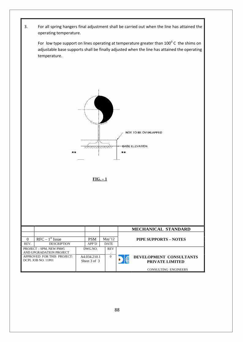
3. For all spring hangers final adjustment shall be carried out when the line has attained theoperating temperature.
For low type support on lines operating at temperature greater than 1000 C the shims onadjustable base supports shall be finally adjusted when the line has attained the operatingtemperature.
FIG. – 1
MECHANICAL STANDARD
0 RFC – 1st Issue PSM May’12 PIPE SUPPORTS – NOTESREV. DESCRIPTION APP’D DATE
PROJECT – SPM, NEW PM#5AND UPGRADATION PROJECT
DWG.NO. REV.
APPROVED FOR THIS PROJECT:DCPL JOB NO. 11P01
A4.034.210.1Sheet 3 of 3
0 DEVELOPMENT CONSULTANTSPRIVATE LIMITED
CONSULTING ENGINEERS
88

89

90
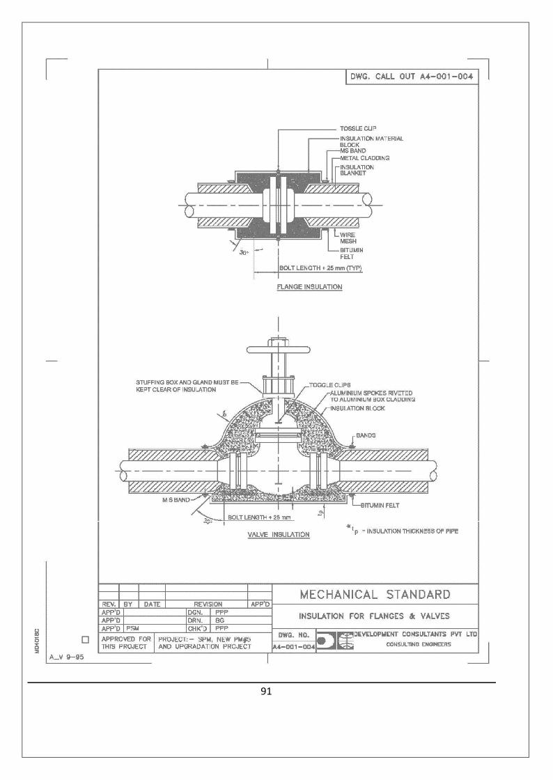
91

92
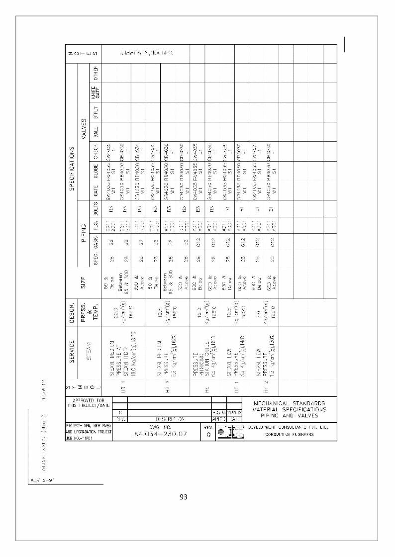
93
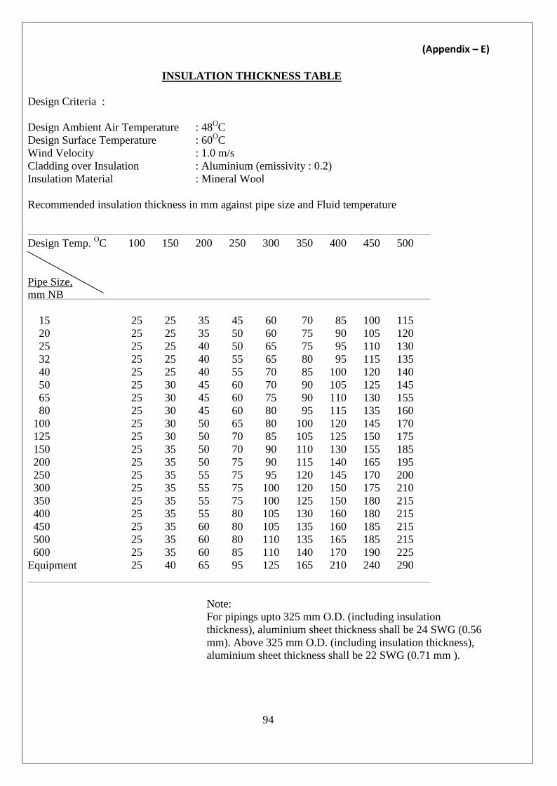
(Appendix – E)
INSULATION THICKNESS TABLE
Design Criteria :
Design Ambient Air Temperature : 48OCDesign Surface Temperature : 60OCWind Velocity : 1.0 m/sCladding over Insulation : Aluminium (emissivity : 0.2)Insulation Material : Mineral Wool
Recommended insulation thickness in mm against pipe size and Fluid temperature
Design Temp. OC 100 150 200 250 300 350 400 450 500
Pipe Size,mm NB
15 25 25 35 45 60 70 85 100 11520 25 25 35 50 60 75 90 105 12025 25 25 40 50 65 75 95 110 13032 25 25 40 55 65 80 95 115 13540 25 25 40 55 70 85 100 120 14050 25 30 45 60 70 90 105 125 14565 25 30 45 60 75 90 110 130 15580 25 30 45 60 80 95 115 135 160
100 25 30 50 65 80 100 120 145 170125 25 30 50 70 85 105 125 150 175150 25 35 50 70 90 110 130 155 185200 25 35 50 75 90 115 140 165 195250 25 35 55 75 95 120 145 170 200300 25 35 55 75 100 120 150 175 210350 25 35 55 75 100 125 150 180 215400 25 35 55 80 105 130 160 180 215450 25 35 60 80 105 135 160 185 215500 25 35 60 80 110 135 165 185 215600 25 35 60 85 110 140 170 190 225
Equipment 25 40 65 95 125 165 210 240 290
Note:For pipings upto 325 mm O.D. (including insulationthickness), aluminium sheet thickness shall be 24 SWG (0.56mm). Above 325 mm O.D. (including insulation thickness),aluminium sheet thickness shall be 22 SWG (0.71 mm ).
94

(Appendix – F)INSULATION SCHEDULE
1. SCHEDULE OF PIPING TO BE INSULATEDFluid Spec. Size (mm, NB) Pipe Length
(m)Temperature (OC) Insulation
Thickness (mm)
HD120100150
9612540 185OC
ReferInsulationThicknessTable
(Appendix – E)
2. SCHEDULE OF VALVES TO BE INSULATEDFluid Code Nominal Valve
Size (mm)Quantity (Nos.) Temperature (OC) Insulation
Thickness (mm)
HD1 15150
202 185OC
Refer InsulationThicknessTable(Appendix – E)
95
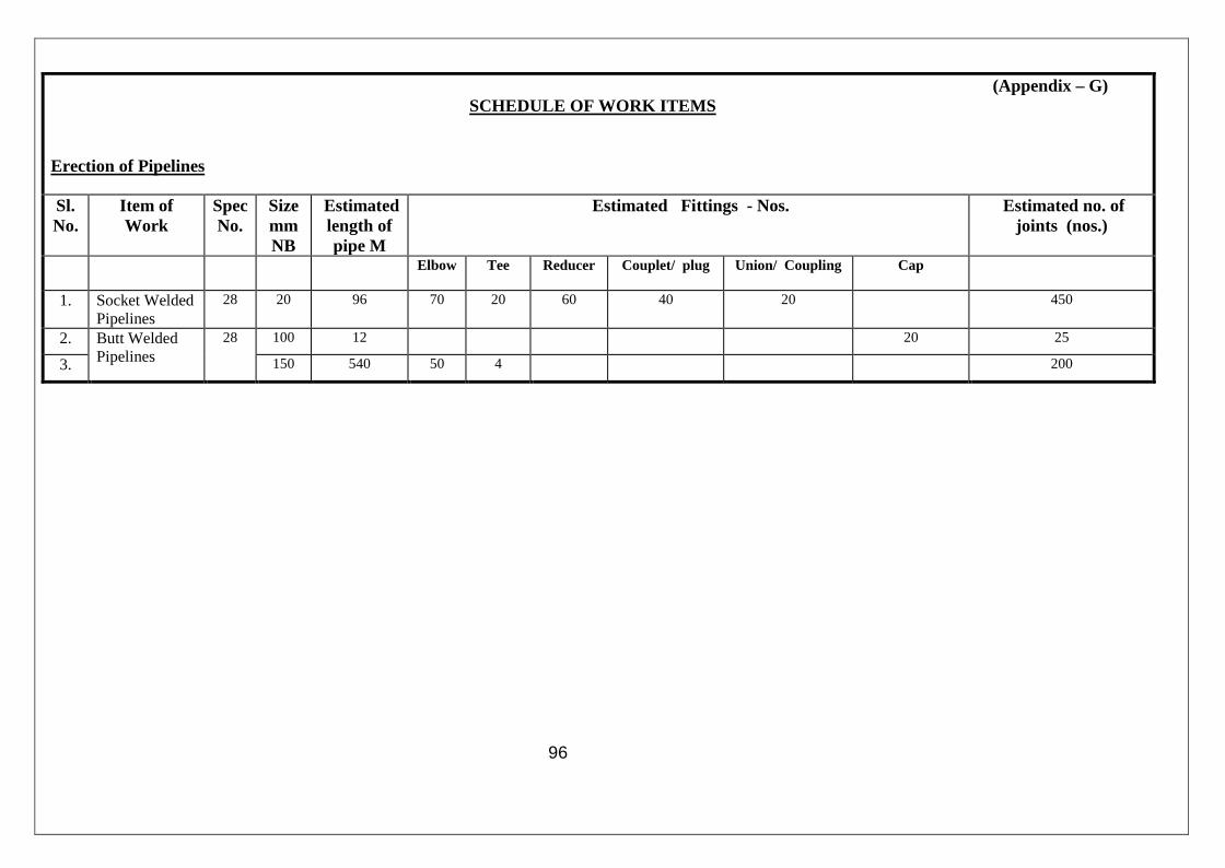
96
(Appendix – G)SCHEDULE OF WORK ITEMS
Erection of Pipelines
Sl.No.
Item ofWork
SpecNo.
SizemmNB
Estimatedlength ofpipe M
Estimated Fittings - Nos. Estimated no. ofjoints (nos.)
Elbow Tee Reducer Couplet/ plug Union/ Coupling Cap
1. Socket WeldedPipelines
28 20 96 70 20 60 40 20 450
2. Butt WeldedPipelines
28 100 12 20 25
3. 150 540 50 4 200

PROPOSAL SHEETSANNEXURE I THRU’ IV
97

PROPOSAL SHEETS
ANNEXURES TO TENDER SPECIFICATION
(To be filled by the Successful Bidder)
1.0.0 The Bidder shall fill in the Technical information and the data sheets required in the followingAnnexures after award of contract.
Annexure – I : Schedule of Items under Tenderer’s
Scope of supply
Annexure – II : Technical Particulars
Annexure – III : Progress Schedule
98

ANNEXURE – I
SCHEDULE OF ITEMS UNDER TENDERER’S SCOPE OF SUPPLY
(Use Separate Sheets for Each Item)
The Tenderer shall submit this Schedule of Items to show his Scope of Supply quantitatively (AdditionalSheets may be used if necessary)
Sl.No. Spec. Code * Item* Size, mm NB Quantity, Nos.
99
* ‘Spec. Code’ and ‘Item’ should be indicated exactly the same way as indicated inAppendix-B enclosed.
100

ANNEXURE – IITECHNICAL PARTICULARS
The Tenderer shall furnish technical information for the materials for a given size range as indicated inMechanical Standard Sheets, (Appendix-D) covered by this Tender Document in the following formatwithout which Tender shall be considered as incomplete. The Tenderer must fill in separate sheets forseparate specification Code Nos. as applicable for this offer.
1.00.00 General
1.01.00 Item :
1.02.00 Specification Code :
1.03.00 Name and Address of the :Manufacturer
1.04.00 Size/Size Range, mm NB :
2.00.00 Technical Specification
2.01.00 Applicable Basic Code/ :Standard/Specificationfor design/fabricationmanufacture
2.02.00 Material of Construction :
2.03.00 Dimensional Standard & : Size NB, mm Thickness,mmThickness
2.04.00 Minimum length per Piece :of Pipe, M
2.05.00 End Preparation Standard :
2.06.00 Basic Codes and Standards :for testing the following asapplicable
2.06.01 Material :
i) Chemical Composition :
ii) Mechanical :
iii) Metalographic :
101
ANNEXURE - IITECHNICAL PARTICULARS (Cont’d.)
2.06.02 Hydrostatic :
2.06.03 Non Destructive :
i) Radiographic :
ii) Ultrasonic :
iii) Eddy Current :
2.06.04 Hydrostatic Test Pressure :kg/cm2g
2.06.05 Minimum duration of Hydro- :static Test, Minutes
2.07.00 Basic Codes and Standards :for inspection Requirement
2.08.00 Certification Requirement :
2.09.00 Marking Standard :
2.10.00 Type of Surface protection :given before shipment
102

ANNEXURE - II
TECHNICAL PARTICULARS (Cont’d.)
THERMAL INSULATION
1.00.00 INSULATING MATERIAL
1.01.00 Trade Name :
1.02.00 Manufacturer :
1.03.00 Insulating Material Offered exactly :conforms to Code
1.04.00 Test results conform to relevant :Standards ?
2.00.00 OTHER MATERIALS
2.01.00 Weather Proofing Jacket :(Hot Insulation)
2.02.00 Wire Netting (hot insulation) :
2.03.00 Sewing Wire (hot insulation) :
2.04.00 Sealing Material (hot insulation) :
3.00.00 GENERAL
3.01.00 Method of Application of Insulation :is as specified
3.02.00 Other materials like MS Rods, Flats and :other materials as indicated in thespecification and as shown in theattached drawings supplied asnecessary?
3.03.00 All Consumables like welding electrodes: Yes/Noetc supplied as necessary.
103
ANNEXURE - II
TECHNICAL PARTICULARS (Cont’d.)
3.04.00 Erection Tools & Tackles, e.g. : Yes/Noscaffolding, welding sets, etc.arranged as necessary?
3.05.00 Drawing on application procedure : Yes/Nofurnished?
3.06.00 Illustrative catalogue on the types of : Yes/Nomaterials offered furnished?
104

ANNEXURE - IIIPROGRESS SCHEDULE
The Tenderer shall indicate the time required for different phases of work under the scope of thisSpecification in the format produced below. The time shall be mentioned in number of works considering thedate of issue of Letter / Telex/Fax/E-Mail of Intent or Purchase Order as zero date, the time shall include thefollowing activities in sequence.
ClauseNo.
Activity Time in Week.
1.00.00 Procurement of Raw Materials :
1.01.00 Start Issuing Orders :
1.02.00 Complete Issuing Orders :1.03.00 Start receiving at works :
1.04.00 Complete receiving at Works :
2.00.00 Purchase Order for Boughtout Items :
2.01.00 Start issuing Orders :
2.02.00 Complete issuing Orders :2.03.00 Start receiving at Works :
2.04.00 Complete receiving at Works :
3.00.00 Manufacture at Works :
3.01.00 Start Manufacture :
3.02.00 Complete Manufacture :
4.00.00 Testing at Manufacturers’ Works :
4.01.00 Start Testing :
4.02.00 Complete Testing :
105
ANNEXURE - IIIPROGRESS SCHEDULE (Cont’d.)
ClauseNo.
Activity Time in Week.
5.00.00 Delivery at site :
5.01.00 Start delivery F.O.R. , Hoshangabad :5.02.00 Complete delivery F.O.R., Hoshangabad :5.03.00 Arrival of first consignment at site
(estimated):
6.00.00 Erection :
6.01.00 Start Erection at site :
6.02.00 Complete Erection at site :
7.00.00 Testing at Stie :
7.01.00 Start Testing :
7.02.00 Complete Testing :
8.00.00 Commissioning :
8.01.00 Start Trial Run :
8.02.00 Complete Commissioning :
106

(Section VIII)
QUALITY CONTROL REQUIREMENTS
1.00.00 QUALITY ASSURANCE PROGRAMME
1.01.00 To ensure that the equipment and services under the scope of Contract whether manufacturedor performed within the Contractor's works or at his Sub-contractor's premises or at the SPM'sSite or at any other place or work are in accordance with the specifications, the Contractor shalladopt suitable quality assurance program to control such activities at all points, as necessary.Such programs shall be detailed by the Contractor and shall require acceptance and approval bythe SPM/DCPL before the award of Contract.
1.02.00 A quality assurance program of the Contractor shall generally cover the following:a) His organization structure for the management and implementation of the proposed quality
assurance programs.b) Qualification data for key personnel.c) Use of suitably qualified and experienced personnel in required number for each type of
work.d) The procedure for quality assurance in design & engineering.e) The methods, procedures and program for presenting, collating and assessing information
from the various sources, and its incorporation in designed submissions.f) Documentation control system.g) The procedure for purchase of materials, parts, components and selection of
Sub-contractor's services including vendor analysis, source inspection, incoming raw materialinspection, verification of materials purchased etc.
h) The method of protection, storage, stock control and issue of materials at site.i) System for shop manufacturing and site erection control including process controls and
fabrication and assembly controls.j) Inspection, sampling, testing, and acceptance procedures for plant and materials delivered
to site.k) Control of non-conforming items and system for corrective actions.l) Inspection and test procedure both for manufacture and all site related works.m) Control of calibration and testing of measuring and testing equipment.n) System for quality audit and self-monitoring of QA Systems.o) System for indication and appraisal of inspection status.p) System for handling, storage and delivery to site.q) Final inspection and certification of completed sections of work.r) Site security procedures.s) The recording and processing of variations to the Works and their incorporation on record
drawings.t) System for maintenance of recordsu) Furnishing of quality plans for design & engineering, manufacturing and field activities
detailing out the specific quality control procedure adopted for controlling the qualitycharacteristics relevant to each item of work.
107
1.03.00 The Quality Assurance arrangements shall include the preparation of and adherence todocumented quality plans. After approval by the SPM/DCPL Engineer the Quality Assurancearrangements shall form an integral part of the Contract. No changes shall be made without theprior written approval of the SPM Engineer.
1.04.00 The Bidder shall list his proposed sub-contractors and shall provide the following information inrespect of each sub-contractor:a) The items which the Bidder proposes to sub-contract.b) The basis on which the Bidder has assessed, or proposes to assess, the quality assurance
arrangements of the sub-contractors.c) How sub-contractors' quality plans/procedures will be approved, monitored and audited on
site during the Contract period.d) The results of any recent evaluations and audits of the sub-contractor which have been
performed by the Bidder or other organizations external to the sub-contractor.
The Bidder shall also state the level of detail of the Quality Plan proposed for each sub-contracted item.The information supplied in response to the above in the Tender shall be deemed a part ofthe Bidder's proposed Quality Assurance arrangements.
1.05.00 The Contractor shall provide documentation in such a manner that the SPM Engineer is therebyenabled to satisfy himself as to the effectiveness with which the Contractor is implementingthose provisions of the agreed and accepted Quality Assurance arrangements which relate tothe monitoring by the Contractor to sub-tier Quality Assurance arrangements.
1.06.00 Audits of sub-tier Quality Assurance arrangements shall be recorded in such a manner that therelevant documentation constitutes, inter alia, objective evidence of the extent of the audits andof the effectiveness with which they have been conducted. All such documentation relating toany one audit shall be made available to the Engineer, on request, as a single self-containeddocument or as one discrete self-contained package of documents.
1.07.00 General Requirements - Quality Assurance
1.07.01 All materials, components, equipment and systems covered under this specification shall beprocured, manufactured, erected, commissioned and tested at all the stages, as per acomprehensive Quality Assurance Program. Inspections, and tests at works including shopperformance tests and test at site for all equipment and systems shall be as per respective codesand standards and also as required in the specification.
1.07.02 Bidder shall furnish a detailed and exhaustive list of all inspections and tests that he or his sub-contractors shall carry out at works and at site for all equipment and systems covered under thisspecification. The list shall have to be approved by the DCPL/SPM before Award of Contract.
108
1.07.03 The Quality Plan for design and engineering shall cover the procedure for independentverification, validation and assessment of designs in terms of fitness for purpose,constructability, safety, compliance with standards, maintenance requirements, costeffectiveness etc.
1.08.00 The detailed Quality Plans for manufacturing and field activities (where applicable) shall bedrawn up by the Bidder separately and shall be submitted to DCPL/SPM for approval. Scheduleof finalization of such Quality Plans shall be finalized before award of Contract.
1.08.01 Manufacturing Quality Plan will detail out for all the components and equipment, varioustests/inspections to be carried out as per the requirements of this specification and standardsmentioned therein and quality practices and procedures followed by Contractor's QualityControl organization, the relevant reference documents and standards, acceptance norms,inspection documents raised etc., during all stages of materials procurement, manufacture,assembly and final testing/performance testing.
1.08.02 Field Quality Plans will detail out for all the equipment, the quality practices and procedures etc.to be followed by the Contractor's site Quality Control organization, during various stages of siteactivities from receipt of materials/equipment at site.
1.09.00 The Bidder shall also furnish copies of the reference documents/plant standards/acceptancenorms/tests and inspection procedure etc., as referred in Quality Plans along with Quality Plans.These Quality Plans and reference documents/standards etc. shall be subject to DCPL/SPM'sapproval without which manufacture shall not proceed. These approved documents shall form apart of the Contract. In these approved Quality Plans, DCPL/SPM representative shall identifyCustomer Hold Points (CHP). A Customer Hold Point signifies a stage in any item of work whichrequires documented proof of approval based on tests/checks which shall be carried out inpresence of the SPM/DCPL’s Engineer or his authorized representative and beyond which thework shall not proceed without consent of SPM/DCPL in writing.
1.10.00 The Contractor shall submit to the Engineer complete field welding schedule for all field weldingactivities for approval. The field welding schedule shall be submitted along with all supportingprocedures like welding procedures, heat treatment procedures, NDT procedures etc.
1.11.00 No material shall be dispatched from the manufacturer's works before the same is acceptedsubsequent to pre-dispatch final inspection including verification of records of all previoustests/inspections by SPM/DCPL’s Engineer, and duly authorized for dispatch.
1.11.01 Quality assurance/Inspection group of SPM/DCPL would issue a Material Dispatch ClearanceCertificate (MDCC) after the inspection clearance which will enable the Contractor to dispatchthe equipment and claim the payment.
109
1.12.00 All materials used or supplied shall be accompanied by valid and approved materials certificatesand tests and inspection report. These certificates and reports shall indicate the sheet numbersor other such acceptable identification numbers of the material. The material certified shall alsohave the identification details stamped on it.
1.13.00 Castings and forgings used for construction shall be of tested quality. Details of results ofchemical analysis, heat treatment record, and mechanical property test results shall befurnished.
1.14.00 All welding and brazing shall be carried out as per procedure drawn and qualified in accordancewith requirements of ASME Section-IX/BS-4870 or other International equivalent standardacceptable to the DCPL/SPM.
All brazers, welders etc. employed on any part of the contract at Contractor's/Sub-Contractor'sworks or at site shall be qualified as per the requirement of IBR or ASME Section-IX or BS-4871or equivalent international standards. Such qualification tests shall be conducted in presence ofCIB and /or SPM/DCPL’s Engineer.
1.15.00 All non-destructive examinations (NDT) shall be carried out in accordance with approvedinternational standard. The NDT operator shall be qualified as per SNT-TC-IA (of AmericanSociety of non- destructive examination). Results of NDT shall be properly recorded andsubmitted to SPM/DCPL.
1.16.00 All the sub-vendors proposed by the Contractor for procurement of equipment, material andservices and their quality assurance plans shall be subject to DCPL/SPM’s approval.
1.16.01 The list of all major sub-contractors would be submitted along with the Tender and this shall bemutually discussed and agreed to at the time of award of Contract. Regarding the various otherminor sub-vendors, the list would be submitted within six (6) months of the award of theContract and shall be mutually discussed and agreed to.
1.17.00 All the purchase specifications for the major bought-out items, list of which shall be drawn up bythe Contractor and finalized with the DCPL/SPM shall be furnished to the DCPL/SPM forcomments and subsequent approval before orders are placed.
1.18.00 SPM reserves the right to carry out quality audit and quality surveillance of the systems andprocedures of the Contractor's or their sub vendor's quality management and control activities.The Contractor shall provide all necessary assistance to enable the SPM carry out such audit andsurveillance.Quality audit/approval of the results of tests and inspection shall not prejudice theright of the SPM to reject an equipment not giving the desired performance after erection andshall not in any way limit the liabilities and responsibilities of the Contractor in earningsatisfactory performance of equipment as per specification.
110

1.19.00 Quality requirements for main equipment shall equally apply for spares and replacement items.
1.20.00 Repair/rectification procedures to be adopted to make any job acceptable shall be subject to theapproval of the DCPL/SPM.
1.21.00 Quality Assurance Document
1.21.01 The Contractor shall be required to submit two (2) copies and two (2) sets of electronic files ofthe following Quality Assurance documents within three (3) weeks after dispatch of theequipment:a) Material mill test reports on components as specified by the specification.b) The inspection plan with verification, inspection plan check points, verification sketches, if
used and methods used to verify that the inspection and testing points in the inspection planwere performed satisfactorily.
c) Non-destructive examination results/reports including radiography interpretation reports.d) Factory tests results for testing required as per applicable codes and standards referred in
the specification.e) Welder identification list listing welders and welding operator's qualification procedure and
welding identification symbols.
f) Sketches and drawings used for indicating the method of traceability of the radiographs tothe location on the equipment.
g) Stress relief time temperature charts.
h) Inspection and test reports duly signed by QA personnel of the SPM and Contractor for theagreed customer hold points. During the course of inspection, the following will also berecorded:
i) When some important repair work is involved to make the job acceptable.
ii) The repair work remains part of the accepted product quality.
iii) Letter of conformity certifying that the requirement is in compliance with finalizedspecification requirements.
1.22.00 Inspection, Testing and Inspection Certificates
The Bidder shall communicate to the SPM prior to the readiness of the machine to arrangevisit of representative for pre dispatch inspection. The inspection will be carried out for fiveworking days by five authorized representatives of the SPM for monitoring the progress of thevarious facilities of the machine at the suppliers work.
111
1.22.01 The Engineer, his duly authorized representative and/or an outside inspection agency acting onbehalf of the SPM shall have access at all reasonable times to inspect and examine the materialsand workmanship of the works during its manufacture or erection and if part of the works isbeing manufactured or assembled on other premises or works, the Contractor shall obtain forthe Engineer and for his duly authorized representative permission to inspect as if the workswere manufactured or assembled on the Contractor's own premises or works.
1.22.02 The Contractor shall give the Engineer/Inspector fifteen (15) days written notice of any materialbeing ready for testing. Such tests shall be to the Contractor's account except for the expensesof the Inspector. The Engineer/Inspector, unless the witnessing of the tests is virtually waived,will attend such tests within fifteen (15) days of the date on which the equipment is notified asbeing ready for test/inspection failing which the Contractor may proceed with test which shallbe deemed to have been made in the Inspector's presence and he shall forthwith forward to theInspector duly certified copies of test reports in six (6) copies.
1.22.03 The Engineer or Inspector shall within fifteen (15) days from the date of Inspection as definedherein give notice in writing to the Contractor, or any objection to any drawings and all or anyequipment and workmanship which is in his opinion are not in accordance with the Contract.The Contractor shall give due consideration to such objections and shall either makemodifications that may be necessary to meet the said objections or shall confirm in writing tothe Engineer/Inspector giving reasons therein, that no modifications are necessary to complywith the contract.
1.22.04 When the factory tests have been completed at the Contractor's or sub-contractor's works, theEngineer/Inspector shall issue a certificate to this effect fifteen (15) days after completion oftests but if the tests are not witnessed by the Engineer/ Inspectors, the certificate shall be issuedwithin fifteen (15) days of the receipt of the Contractor's test certificate by theEngineer/Inspector. Failure of the Engineer/Inspector to issue such a certificate shall not preventthe Contractor from proceeding with the works. The completion of these tests or the issue ofthe certificates shall not bind the SPM to accept the equipment should it, on further tests aftererection be found not to comply with the Contract.
1.22.05 In all cases where the contract provides for tests whether at the premises or works of theContractor or any sub-contractor, the Contractor, except where otherwise specified shallprovide free of charge such items as labour, materials, electricity, fuel, water, stores, apparatusand instruments as may be reasonably demanded by the Engineer/Inspector or his authorizedrepresentatives to carry out effectively such tests on the equipment in accordance with theContractor and shall give facilities to the Engineer/Inspector or to his authorized representativeto accomplish testing.
1.22.06 To facilitate advance planning of inspection in addition to giving inspection notice, theContractor shall furnish quarterly inspection programme indicating schedule dates of inspectionat customer hold points and final inspection stages. Updated quarterly inspection plans will bemade for each three consecutive months and shall be furnished before beginning of eachcalendar month.
112
1.23.00 Archiving
In addition to the requisite number of hard copies as specified, four (4) copies of all qualityassurance documents, final inspection and test certificates etc. shall be made available tothe SPM in Compact Disks before handing over of the plant.
113

(Section IX)
QUALIFICATION/ELIGIBILITY CRITERIA
1. Bidder Firm should have manufactured, supplied, installed and commissioned at least one similar IBRpiping work of different sizes with minimum total length of 648 meters, out of which 540 meter lengthshould be of size not less than 150 mm NB, in one plant, complete with all fittings during last five (5)years ending 31st March 2012.
2. The Bidder firm must have an annual capacity to manufacture and supply at least (1) no. similarinstallation as above.
3. The average annual turn-over of the Bidder during the last three (3) years, ending 31st March2012 should be at least Rs.25.50 Lac.
4. The Bidder firm should not have suffered any financial loss for more than one (1) year during thelast three (3) years ending 31st March 2012.
5. The net worth of the Bidder firm should not have eroded by more than 30% in the last three (3)years ending 31st March 2012.
6. Either the Indian agent on behalf of the principal/OEM or principal/OEM itself can bid bothcannot bid simultaneously for the same item/product in the same tender.
7. If an agent submits bid on behalf of the principal/OEM, the same agent shall not submit a bid onbehalf of another principal/OEM for the same item/product.
8. The bidder firm should be authorized by IBR authority to carry out such type of steam pipingwork.
NOTE:
1. All experience, past performance and capacity/capability related data should be certified by theauthorized signatory of the Bidder firm. The credentials regarding experience and pastperformance to the extent required as per the above eligibility criteria as submitted by the Biddermay be verified from the parties for whom work has been done.
2. All financial standing data should be certified by certified accountants’ e.g. CharteredAccountants (CA) in India and Certified Public Accountant/ Chartered Accountant of othercountries.
3. MOST IMPORTANT NOTE:BIDDER TO FURNISH STIPULATED DOCUMENTS IN SUPPORT OF FULFILLMENT OF QUALIFYINGCRITERIA. NON-SUBMISSION OR INCOMPLETE SUBMISSION OF DOCUMENTS MAY LEAD TOREJECTION OF OFFER.
114
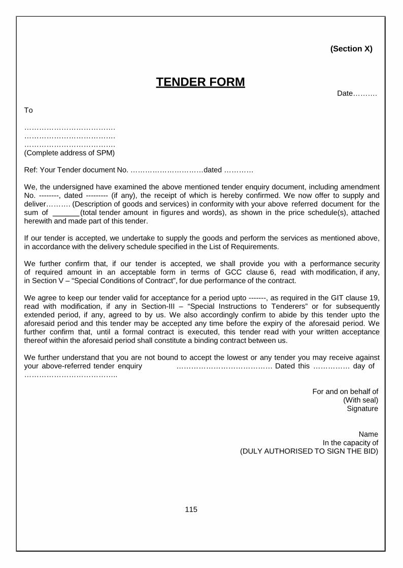
(Section X)
TENDER FORMDate……….
To
……………………………….……………………………….……………………………….(Complete address of SPM)
Ref: Your Tender document No. …………………………dated …………
We, the undersigned have examined the above mentioned tender enquiry document, including amendmentNo. --------, dated --------- (if any), the receipt of which is hereby confirmed. We now offer to supply anddeliver………. (Description of goods and services) in conformity with your above referred document for thesum of (total tender amount in figures and words), as shown in the price schedule(s), attachedherewith and made part of this tender.
If our tender is accepted, we undertake to supply the goods and perform the services as mentioned above,in accordance with the delivery schedule specified in the List of Requirements.
We further confirm that, if our tender is accepted, we shall provide you with a performance securityof required amount in an acceptable form in terms of GCC clause 6, read with modification, if any,in Section V – “Special Conditions of Contract”, for due performance of the contract.
We agree to keep our tender valid for acceptance for a period upto -------, as required in the GIT clause 19,read with modification, if any in Section-III – “Special Instructions to Tenderers” or for subsequentlyextended period, if any, agreed to by us. We also accordingly confirm to abide by this tender upto theaforesaid period and this tender may be accepted any time before the expiry of the aforesaid period. Wefurther confirm that, until a formal contract is executed, this tender read with your written acceptancethereof within the aforesaid period shall constitute a binding contract between us.
We further understand that you are not bound to accept the lowest or any tender you may receive againstyour above-referred tender enquiry ………………………………… Dated this …………… day of………………………………..
For and on behalf of(With seal)Signature
NameIn the capacity of
(DULY AUTHORISED TO SIGN THE BID)
115
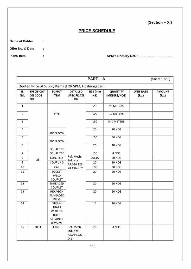
(Section – XI)
PRICE SCHEDULE
Name of Bidder :
Offer No. & Date :
Plant/ Item : SPM’s Enquiry Ref. :…………………………….
116
PART – A (Sheet 1 of 2)
Quoted Price of Supply Items (FOR SPM, Hoshangabad)SL.
NO.SPECIFICATION CODENO.
SUPPLYITEM
DETAILEDSPECIFICATI
ON
SIZE (mmNB)
QUANTITY(METERS/NOS)
UNIT RATE(Rs.)
AMOUNT(Rs.)
1
28
PIPE
Ref. Mech.Std. Nos.A4.034.226.28.1 thru’ 2
20 96 METERS
2 100 12 METERS
3 150 540 METERS
490° ELBOW
20 70 NOS
590° ELBOW
150 50 NOS
6EQUAL TEE
20 20 NOS
7 EQUAL TEE 150 4 NOS8 CON. RED. 20X15 60 NOS9 COUPLING 20 20 NOS
10 CAP 100 20 NOS11 SOCKET
WELDCOUPLET
20 20 NOS
12 THREADEDCOUPLET
20 20 NOS
13 HEXAGONAL HEADED
PLUG
20 20 NOS
14 STEAMTRAPS
WITH IN-BUILT
STRAINER& VALVE
15 20 NOS
15 BD11 FLANGE Ref. Mech.Std. Nos.A4.034.227.D.1
150 4 NOS

117
PART – A (Sheet 2 of 2)
Quoted Price of Supply Items (FOR SPM, Hoshangabad)SL.
NO.SPECIFICATIONCODENO.
SUPPLYITEM
DETAILEDSPECIFICATION
SIZE (mmNB)
QUANTITY(METERS/NOS)
UNIT RATE(Rs.)
AMOUNT (Rs.)
16 GW4035W1
GATEVALVE
Ref. Sheet 1 ofAppendix-C
15 20 NOS
17 GB4030W1
GATEVALVE
Ref. Sheet 1 ofAppendix-C
150 2 NOS
18 Supply of Thermal Insulation (Unit of Measurement – Meter. Measured along the C.L. of insulated pipe line)
a) INSULATION ON PIPES Ref. of Appendix-F
20 96 METERSb) 100 12 METERSc) 150 540 METERSd) INSULATIO
N ONVALVES
Ref. of Appendix-F15 20 NOS
e) 150 2 NOS
19 Supply of supports, Hangers & Brackets (Quote per Tonne. Quantity shown is indicative only. Actual quantity shall beas measured during erection)
a) Miscellaneous PipeSupports
Ref. Cl. No. 2.01.06 ofSection-VII of thisSpecification
250 Kg
20 Packing & Forwarding charges21 Freight charges including Unloading at site22 Taxes & Duties as applicable23 Total Price of Supply Items (1 to 22) in Figures24 Total Price of Supply Items (1 to 22) in Words

118
PART – B (Sheet 1 of 2)
Quoted Price of Services (FOR SPM, Hoshangabad)SL.
NO.SPECIFICATION CODENO.
ITEM DETAILEDSPECIFICATIO
N
SIZE (mmNB)
QUANTITY(METERS/NOS)
UNIT RATE (Rs.) AMOUNT(Rs.)
1
28
PIPE
Ref. Mech.Std. Nos.A4.034.226.28.1 thru’ 2
20 96 METERS
2 100 12 METERS
3 150 540 METERS
490° ELBOW
20 70 NOS
590° ELBOW
150 50 NOS
6EQUAL TEE
20 20 NOS
7 EQUAL TEE 150 4 NOS8 CON. RED. 20X15 60 NOS9 COUPLING 20 20 NOS
10 CAP 100 20 NOS11 SOCKET
WELDCOUPLET
20 20 NOS
12 THREADEDCOUPLET
20 20 NOS
13 HEXAGONAL HEADED
PLUG
20 20 NOS
14 STEAMTRAPS WITH
IN-BUILTSTRAINER &
VALVE
15 20 NOS
15 BD11 FLANGE Ref. Mech.Std. Nos.A4.034.227.D.1
150 4 NOS
16 GW4035W1 GATE VALVE Ref. Sheet 1of Appendix-C
15 20 NOS
17 GB4030W1 GATE VALVE Ref. Sheet 1of Appendix-C
150 2 NOS

Note:-
1. Cost of fabrication and erection of the above items should be inclusive of cost of sandblasting, cleaningand painting as per requirement of the specification.
2. The method of evaluation of L1 criteria for awarding the Contract shall be on consolidated offer by thebidder and will be decided taking into consideration of total offered price including Part (A+B) as above.
Bidder’s Signature_________________________
119
PART – B (Sheet 2 of 2)
Quoted Price of Services (FOR SPM, Hoshangabad)SL.
NO.SPECIFICATIONCODENO.
ITEM DETAILEDSPECIFICATION
SIZE (mmNB)
QUANTITY(METERS/NOS)
UNIT RATE(Rs.)
AMOUNT (Rs.)
18 Application of Thermal Insulation (Unit of Measurement – Meter. Measured along the C.L. of insulated pipe line)a)
INSULATIONON PIPES
Ref. of Appendix-F20 96 METERS
b) 100 12 METERSc) 150 540 METERSd) INSULATION
ON VALVESRef. of Appendix-F 15 20 NOS
e) 150 2 NOS19 Fabrication of supports, Hangers & Brackets (Quote per Tonne. Quantity shown is indicative only. Actual quantity shall
be as measured during erection)a) Miscellaneous
Pipe SupportsRef. Cl. No.2.01.06 ofSection-VII of thisSpecification
250 Kg
20 Taxes & Duties as applicable21 Total Price of Services (1 to 20) in Figures22 Total Price of Services (1 to 20) in Words23 TOTAL ERECTED & COMMISSIONED COST OF PIPING (PART-A + PART-B) in Figures24 TOTAL ERECTED & COMMISSIONED COST OF PIPING (PART-A + PART-B) in Words

(Section XII)QUESTIONAIRE
The tenderer should furnish specific answers to all the questions/ issues mentioned below. Incase a question/ issue does not apply to a tenderer, the same should be answered with theremark “not applicable”.Wherever necessary and applicable, the tenderer shall enclose certified copy as documentaryproof/ evidence to substantiate the corresponding statement.In case a tenderer furnishes a wrong or evasive answer against any of the under mentionedquestion/ issues, its tender will be liable to be ignored.
1. Brief description of Work and services offered:
3. Your permanent Income Tax A/C No. as allotted by the Income Tax Authority of Government ofIndia :Please attach certified copy of your latest /current Income Tax clearance certificate issued bythe above authority.
4. Status :a) Are you currently registered with the Directorate General of Supplies & Disposals
(DGS&D), New Delhi, and/or the National Small Industries Corporation (NSIC), NewDelhi, and/or the present SPMICL and/or the Directorate of Industries of the concernedState Government for the goods quoted? If so, indicate the date up to which you areregistered and whether there is any monetary limit imposed on your registration.
b) Are you currently registered under the Indian Companies Act, 1956 or ant other similarAct ?
Please attach certified copy(s) of your registration status etc. in case your answer(s) to abovequeries is in affirmative.
5. Please indicate name & full address of your Banker(s) :
6. Please state whether business dealings with you currently stand suspended/ banned by anyMinistry/ Deptt. of Government of India or by any State Govt.
……………………….(Signature with date)……………………….……………………….
(Full name, designation & address of the personduly authorized sign on behalf of the tenderer)For and on behalf of
…………………………..…………………………..(Name, address and stamp of the tendering firm)
120

(Section XIII)
BANK GUARANTEE FORM FOR EMD
Not applicable
121

(Section XIV)
MANUFACTURER’S AUTHORIZATION FORM
Not applicable
122
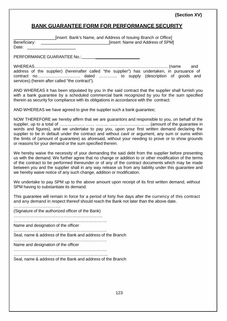
(Section XV)
BANK GUARANTEE FORM FOR PERFORMANCE SECURITY
[insert: Bank’s Name, and Address of Issuing Branch or Office]Beneficiary:Date:
[insert: Name and Address of SPM]
PERFORMANCE GUARANTEE No.:
WHEREAS……………………………………………………………………………………. (name andaddress of the supplier) (hereinafter called “the supplier”) has undertaken, in pursuance ofcontract no…………………………. dated …………. to supply (description of goods andservices) (herein after called “the contract”).
AND WHEREAS it has been stipulated by you in the said contract that the supplier shall furnish youwith a bank guarantee by a scheduled commercial bank recognized by you for the sum specifiedtherein as security for compliance with its obligations in accordance with the contract;
AND WHEREAS we have agreed to give the supplier such a bank guarantee;
NOW THEREFORE we hereby affirm that we are guarantors and responsible to you, on behalf of thesupplier, up to a total of ……………… …… ……… …… …………………. (amount of the guarantee inwords and figures), and we undertake to pay you, upon your first written demand declaring thesupplier to be in default under the contract and without cavil or argument, any sum or sums withinthe limits of (amount of guarantee) as aforesaid, without your needing to prove or to show groundsor reasons for your demand or the sum specified therein.
We hereby waive the necessity of your demanding the said debt from the supplier before presentingus with the demand. We further agree that no change or addition to or other modification of the termsof the contract to be performed thereunder or of any of the contract documents which may be madebetween you and the supplier shall in any way release us from any liability under this guarantee andwe hereby waive notice of any such change, addition or modification.
We undertake to pay SPM up to the above amount upon receipt of its first written demand, withoutSPM having to substantiate its demand.
This guarantee will remain in force for a period of forty five days after the currency of this contractand any demand in respect thereof should reach the Bank not later than the above date.…………………………….(Signature of the authorized officer of the Bank)……………………………………………………….………………………………………………………….Name and designation of the officer………………………………………………………….Seal, name & address of the Bank and address of the Branch………………………………………………………….Name and designation of the officer………………………………………………………….….……………………………………………………….Seal, name & address of the Bank and address of the Branch
123
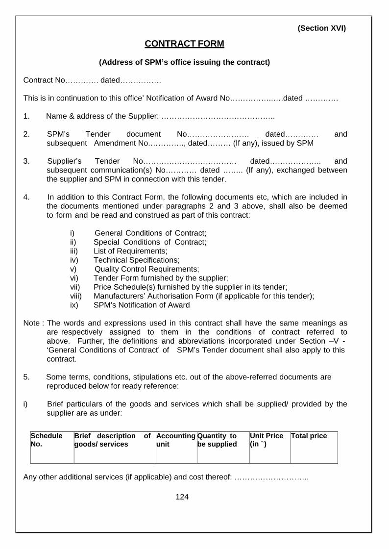
(Section XVI)
CONTRACT FORM
(Address of SPM’s office issuing the contract)
Contract No…………. dated…………….
This is in continuation to this office’ Notification of Award No……………..….dated ………….
1. Name & address of the Supplier: ……………………………………..
2. SPM’s Tender document No…………………… dated…………. andsubsequent Amendment No.…………., dated……… (If any), issued by SPM
3. Supplier’s Tender No……………………………… dated……………….. andsubsequent communication(s) No………… dated …….. (If any), exchanged betweenthe supplier and SPM in connection with this tender.
4. In addition to this Contract Form, the following documents etc, which are included inthe documents mentioned under paragraphs 2 and 3 above, shall also be deemedto form and be read and construed as part of this contract:
i) General Conditions of Contract;ii) Special Conditions of Contract;iii) List of Requirements;iv) Technical Specifications;v) Quality Control Requirements;vi) Tender Form furnished by the supplier;vii) Price Schedule(s) furnished by the supplier in its tender;viii) Manufacturers’ Authorisation Form (if applicable for this tender);ix) SPM’s Notification of Award
Note : The words and expressions used in this contract shall have the same meanings asare respectively assigned to them in the conditions of contract referred toabove. Further, the definitions and abbreviations incorporated under Section –V -‘General Conditions of Contract’ of SPM’s Tender document shall also apply to thiscontract.
5. Some terms, conditions, stipulations etc. out of the above-referred documents arereproduced below for ready reference:
i) Brief particulars of the goods and services which shall be supplied/ provided by thesupplier are as under:
ScheduleNo.
Brief description ofgoods/ services
Accountingunit
Quantity tobe supplied
Unit Price(in `)
Total price
Any other additional services (if applicable) and cost thereof: ………………………..
124

Total value (in figure) (In words)
(ii) Delivery schedule
(iii) Details of Performance Security
(iv) Quality Control
(a) Mode(s), stage(s) and place(s) of conducting inspections and tests.(b) Designation and address of SPM’s inspecting officer
(v) Destination and despatch instructions
(vi) Consignee, including port consignee, if any
(vii) Warranty clause
(viii)Payment terms
(ix) Paying authority
……………………………….(Signature, name and address of SPM’s authorized official)
For and on behalf of……………………
Received and accepted this contract
……………………………………………………………………(Signature, name and address of the supplier’s executive duly authorized to sign on behalf ofthe supplier)
For and on behalf of ………………….………………………(Name and address of the supplier)
……………………. ……………………….(Seal of the supplier)
Date:Place:
125

(Section XVII)
LETTER OF AUTHORITY FOR ATTENDING A BID OPENING
The General ManagerSecurity Paper MillHoshangabadM.P – 461 005
(Refer to clause 24.2 of GIT)
Subject : Authorization for attending bid opening on (date) in the Tender of.
Following persons are hereby authorized to attend the bid opening for the tendermentioned above on behalf ofpreference given below.
(Bidder) in order of
Order of Preference Name Specimen SignaturesI.
II.
Alternate Representative
Signatures of bidder orOfficer authorized to sign the bidDocuments on behalf of thebidder.
Note:
1. Maximum of two representatives will be permitted to attend bid opening. In cases whereit is restricted to one, first preference will be allowed. Alternate representative will bepermitted when regular representatives are not able to attend.
2. Permission for entry to the hall where bids are opened may be refused in caseauthorization as prescribed above is not produced.
126
(Section XVIII)
SHIPPING ARRANGEMENTS FOR LINER CARGOES
Not applicable
127

(Section XIX)
PROFORMA OF BILLS FOR PAYMENTS
(Refer Clause 22.6 of GCC)
Name and Address of the Firm.....................................................................................
Bill No............................................................... Dated.................................................
Purchase order No……………......................... Dated................................................
Name and address of the consignee ...........................................................................
S.No. Authority forpurchase
Description ofStores
Number orquantity
RateRs.
Price perRs.
AmountRs.
Total
1. C.S.T./Sales Tax Amount2. Freight (if applicable)3. Excise Duty (if applicable)4. Packing and Forwarding charges (if applicable)5. Others (Please specify)6. PVC Amount (with calculation sheet enclosed)7. (-) deduction/Discount8. Net amount payable (Rupees in Words)
Despatch detail:
RR No. /other proof of despatch.......................... Dated.......................... (enclosed)
Inspection Certificate No..................................... Dated........................... (enclosed)
Modvat Certificate No ................................................................................. (enclosed)
Excise Duty Gate pass…….......................................................................... (enclosed)
Received ............................. (Rupees in Words).........................................................
I hereby certify that the payment being claimed is strictly in terms of the contract and all theobligations on the part of the supplier for claiming that payment has been fulfilled as requiredunder the contract.
Revenue stamp Signature and of Stamp Supplier
128
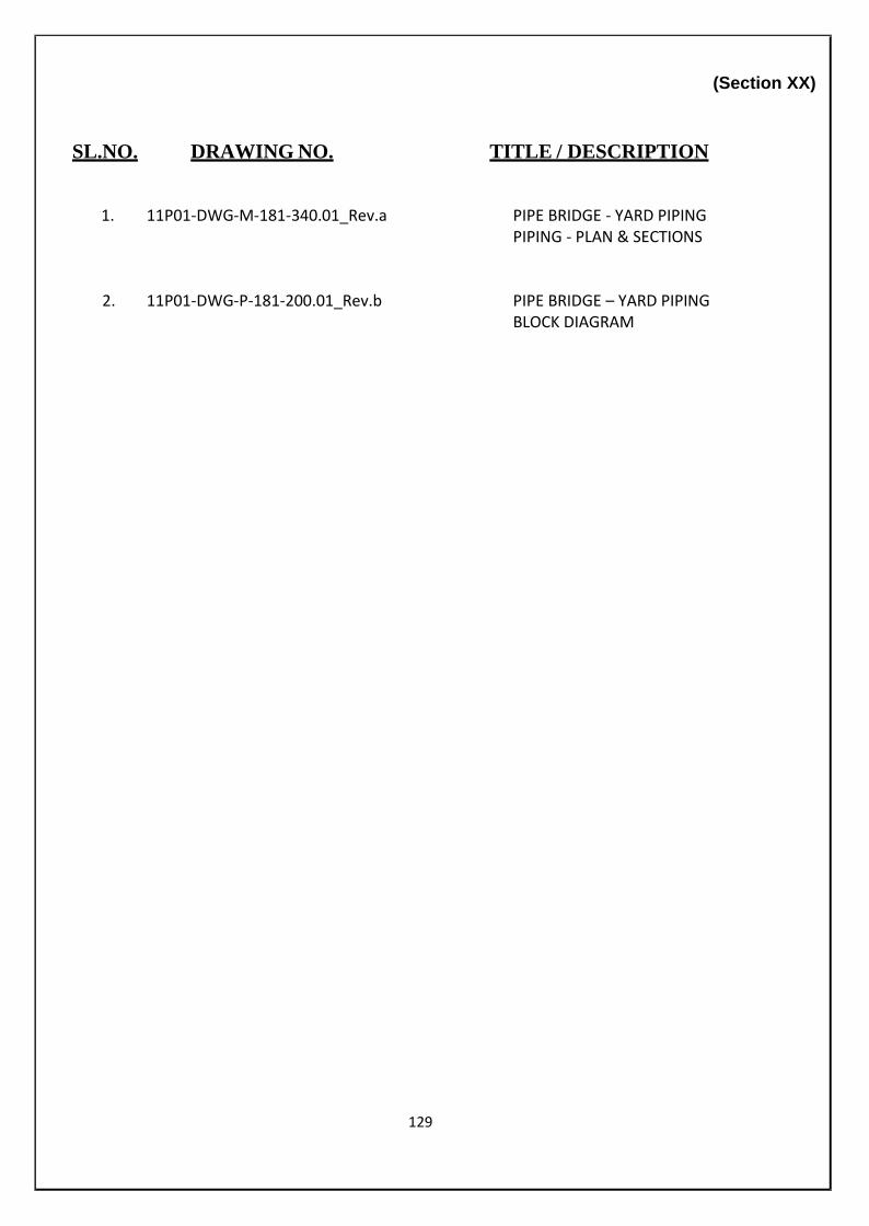
(Section XX)
SL.NO. DRAWING NO. TITLE / DESCRIPTION
1. 11P01-DWG-M-181-340.01_Rev.a PIPE BRIDGE - YARD PIPINGPIPING - PLAN & SECTIONS
2. 11P01-DWG-P-181-200.01_Rev.b PIPE BRIDGE – YARD PIPINGBLOCK DIAGRAM
129