tender turnkey instrumentation hazira -...
TRANSCRIPT

SPECIFICATION FOR TURNKEY INSTRUMENTATION SYSTEM AT HAZIRA �
DOC NO. 0435-JH0911-00-IN-SPC-0002 Rev.B Page 1 of 147
HINDUSTAN PETROLEUM CORPORATION LIMITED
LPG PROJECTS HINDUSTAN BHAWAN, 3RD FLOOR 8, SHOORJI VALLABHDAS MARG
BALLARD ESTATE MUMBAI – 400 001
TENDER DOCUMENT FOR
TURNKEY INSTRUMENTATION JOB
FOR FLOW CONTROL SYSTEMS BETWEEN ONGC
AND HPCL LPG PLANT
AT
HAZIRA LPG PLANT PO ICHCHAPORE
ONGC HAZIRA ROAD DIST SURAT, GUJARAT

SPECIFICATION FOR TURNKEY INSTRUMENTATION SYSTEM AT HAZIRA AND ICCHAPORE
DOC NO. 0435-JH0911-00-IN-SPC-0002 Rev. B Page 2 of 147
INDEX
1. NOTICE INVITING TENDER
2. INSTRUCTION TO BIDDERS
3. SPECIAL TERMS AND CONDITIONS
4. GENERAL TERMS & CONDITIONS
5. TECHNICAL SPECIFICATIONS(SCOPE OF JOBS,SPECS,BOQ, DRGS, DATA SHEETS)

SPECIFICATION FOR TURNKEY INSTRUMENTATION SYSTEM AT HAZIRA AND ICCHAPORE
DOC NO. 0435-JH0911-00-IN-SPC-0002 Rev. B Page 3 of 147
HINDUSTAN PETROLEUM CORPORATION LIMITED (A Govt. of India Enterprise)
NOTICE INVITING TENDER
Electronic digitally signed & sealed (encrypted) e-tenders are invited under ‘Two Bid system’ from eligible Indian Bidders for the following works of HAZIRA LPG project as per details given below-
S. No. Tender No. Job EMD
1.
TURNKEY INSTRUMENTATION JOB FOR
FLOW CONTROL SYSTEMS BETWEEN ONGC AND HPCL
LPG PLANT AT HAZIRA
NIL

SPECIFICATION FOR TURNKEY INSTRUMENTATION SYSTEM AT HAZIRA AND ICCHAPORE
DOC NO. 0435-JH0911-00-IN-SPC-0002 Rev. B Page 4 of 147
SECTION II
BRIEF TO TENDERERS

SPECIFICATION FOR TURNKEY INSTRUMENTATION SYSTEM AT HAZIRA AND ICCHAPORE
DOC NO. 0435-JH0911-00-IN-SPC-0002 Rev. B Page 5 of 147
BRIEF TO THE TENDERERS
1.0 Brief Project Description:
HPCL proposes to construct a new 88 TMPTA LPG Bottling Plant at Hazira. The facilities include 06 Bays T/T Loading bays. The Product receipt shall be from ONGC Hazira through a 08” Dia cros Country Pipeline and 240 Cum/Hr LPG Booster pumps located at ONGC Premises approx at 3.0 Km from proposed LPG Plant.
THE TURNKEY INSTRUMENTATION JOB FOR FLOW CONTROL SYSTEMS BETWEEN ONGC AND HPCL LPG PLANT
is required to be carried out at Hazira for the commissioning of the Facilities as per the Scope identified in this Tender Document. Detailed scope is outlined in Page 72 of this tender document
CONTACT PERSONS : The Following Persons shall be referred via Emails for seeking any clarification with respect to Technical Aspects of this tender Contact Persons at HQO : Sh. P. S. MURTHY , CHIEF MANAGER – LPG PROJECTS, HINDUSTAN BHAVAN 3, 8 S. V MARG, BALLARD ESTATE, MUMBAI 400001 (022 -2263 7072) Email: [email protected] Sh. S. K SINGH, EXE PROJECT ENGINEER ( 022-2263 7079) Email: [email protected] Contact Person at Hazira Site Sh ASHUTOSH PAL, EXEC PROJECT ENGINEER – LPG PROJECTS, HAZIRA LPG PROJECT SITE (02616454569, 09099027766) Email : [email protected] The Following Persons shall be referred via Emails for seeking any clarification with respect to Commercial Aspects of this tender Mr Prabakar Sant – Manager EP&P LPG, Hindustan Bhavan 3, 8 S.V. Marg, Ballard Estate, Mumbai-400001 (022 22637013) Email : [email protected]

SPECIFICATION FOR TURNKEY INSTRUMENTATION SYSTEM AT HAZIRA AND ICCHAPORE
DOC NO. 0435-JH0911-00-IN-SPC-0002 Rev. B Page 6 of 147
2.0 COMPLETION PERIOD:
4 MONTHS (FOUR MONTHS) FROM THE DATE OF ISSUE OF
LOI/Purchase Order or Advise to start works from User Department.
3.0 BID QUALIFICATION CRITERIA AS MENTIONED UNDERNEATH IS
APPLICABLE FOR THIS TENDER.
a) Vendor should have successfully carried out at least 01 job of
similar nature (Turnkey Instrumentation jobs in POL OR LPG
Bottling Plant, Plant control & Tankfarm Management Services
including supply of Hardware & SOftware) in any OMC
(HPCL/IOCL/BPCL) of value not less than 1.2 Crores (excluding
AMC Services) in the past 07 Years upto June11. The Job should
have been completed in all aspects. Vendor shall enclose
Purchase Order of the Job along with Completion certificate
issued from client as evidence of having accomplished the
requirement.
b) Vendor should be a regular Executor/Integrator of Terminal
Instrumentation jobs.
c) Vendor should have an average annual financial turnover of 1.6
Crores in the last 03 financial Years ending with March 2010.
Balance Sheets of last three years shall be enclosed In Technical
Bid

SPECIFICATION FOR TURNKEY INSTRUMENTATION SYSTEM AT HAZIRA AND ICCHAPORE
DOC NO. 0435-JH0911-00-IN-SPC-0002 Rev. B Page 7 of 147
4.0 Information/Documents required along with Application:
1) Title, style and postal address of the firm.
2) Communication particulars including telephone numbers, fax
numbers and e-mail address.
3) List of available technical manpower with their academic
qualification, experience and fields of specialization.
4) Integrity Pact: Duly Signed and Witnessed Hard Copy of the
Integrity Pact (as per the format enclosed after GENERAL TERMS
AND CONDITIONS) shall be submitted along with the above
documents. Failure to sign the Integrity Pact shall lead to outright
rejection of bid.
5) EMD Is Not Applicable for this Tender
5.0 GENERAL INFORMATION
i) (This Clause is not applicable for this Tender)
ii) Bidder can view the tender Document at HPCL website
http://www.hindustanpetroleum.com however bidders are not allowed to
quote on the basis of such downloaded document from website and
such offers shall not be considered.
iii) Bid document is non-transferable.
iv) For submitting the bid on-line it would be mandatory for
bidders to obtain digital certificate (which will enable data encryption as
well as digital signing). For information regarding digital certificate,
bidders may visit http://www.cca.gov.in. For submitting the bid online,

SPECIFICATION FOR TURNKEY INSTRUMENTATION SYSTEM AT HAZIRA AND ICCHAPORE
DOC NO. 0435-JH0911-00-IN-SPC-0002 Rev. B Page 8 of 147
bidders are advised to follow the step by step procedure given under
the link “Vendor Instruction Manual” at website http://eproc.hpcl.co.in.
The on-line bidding would comprise broadly following steps –
• Enrollment by vendor at http://eproc.hpcl.co.in (can be
done without
digital certificate) by clicking the link “Supplier
Registration”.
• The system generated challenge phrase will be sent to
vendor at e-mail address provided by him during
enrollment.
• The vendor would be required to login at
http://eproc.hpcl.co.in with this challenge phrase along with
his user id & password. The vendor has to complete 2
page registration form.
• As soon as vendor fills two page registration form, he
should put a request letter on letterhead (giving tender
number) to HPCL for approving his enrollment. The request
may be sent through fax or e-mail No request for
enrollment approval shall be considered within 72 hours of
tender due date / time.
• After enrollment, vendor would be required to login and
register his digital certificate (to be obtained by vendor) at
website.

SPECIFICATION FOR TURNKEY INSTRUMENTATION SYSTEM AT HAZIRA AND ICCHAPORE
DOC NO. 0435-JH0911-00-IN-SPC-0002 Rev. B Page 9 of 147
• After registering digital certificate vendor can participate in
the public tender.
The vendors who are already enrolled at website:
http://eproc.hpcl.co.in need not to enroll again and vendors who have
already got valid digital certificate (enabling data encryption as well as
digital signing) are not required to procure another digital certificate.
v) HPCL will not be responsible for the cost incurred in
preparation and submission of bids including the cost of digital
certificate, regardless of the conduct of outcome of the biding process.
vi) HPCL shall not be responsible for any expenses incurred by
bidders in connection with the preparation & submission of their bids,
site visit and other expenses incurred during bidding process.
vii) Fax/e-mail bids shall not be accepted.
viii) HPCL reserves the right to accept or reject any one or all the
tenders without assigning any reason.
xi) The entire job will be awarded to one successful bidder
and will not be split.
Hindustan Petroleum Corporation Ltd (HPCL) has developed the
“Grievance Redressal Mechanism" to deal with references / grievances if any
that is received from parties who participated/ intends to participate in the
Corporation Tenders. The details of the same are available on this website.
Completed Tenders in all respect should be submitted on-line at
website http://eproc.hpcl.co.in by the tender due date/ time. Unpriced

SPECIFICATION FOR TURNKEY INSTRUMENTATION SYSTEM AT HAZIRA AND ICCHAPORE
DOC NO. 0435-JH0911-00-IN-SPC-0002 Rev. B Page 10 of 147
(Technical) bids shall be opened on-line and participating bidders can view /
witness the same on-line by logging in at website http://eproc.hpcl.co.in.
Bidders would not be allowed to submit their bid after stipulated tender due
date and time. For details, please refer “INSTRUCTION TO BIDDERS”.
INSTRUCTIONS TO TENDERERS DOCUMENTS TO BE UPLOADED ALONG WITH TECHNICAL BID
1. Documents to be uploaded along with the tender shall be as follows:
Sr.No. Document 1. Technical Bid 2. Details of Job currently in hand with HPCL 3. Integrity Pact duly signed and witnessed IN CASE VENDOR FAILS TO UPLOAD THE ABOVE DOCUMENTS ALONG WITH THEIR

SPECIFICATION FOR TURNKEY INSTRUMENTATION SYSTEM AT HAZIRA AND ICCHAPORE
DOC NO. 0435-JH0911-00-IN-SPC-0002 Rev. B Page 11 of 147
TECHNICAL BID, THEIR BID SHALL LIABLE TO BE REJECTED WITHOUT ANY FURTHER REFERENCE TO THE VENDOR. 2.Validity
Quoted prices shall be valid for a period of 90 days from the due date / extended due date of tender (& subsequently till placement of order in case of successful bidder). 3. The tenderers are advised to visit the site and get acquainted with the site conditions. HPCL will not provide any infrastructure such as water, power, internal roads for construction works. 4. The tenderers should note the site conditions before quoting. The site will be offered on AS IS WHERE IS condition for the execution of this job. It will be the sole responsibility of the Vendor to ensure that they abide by the various rules, regulations, bye-laws and other statutory requirements, etc. imposed by the Government / Semi-Government and / or other local authorities governing execution of this job. The tenderers should study all the documents / conditions etc. in this tender document carefully before submitting their offers. If there are any doubts, they should get clarifications from HPCL, Mumbai through e-procurement but this shall not be a justification for late submission of tenders or extension of due date of the tender. 5.. As far as possible, the tenderers should endeavor not to stipulate any counter terms / conditions or modifications of tender clauses and should quote strictly as per tender conditions. This will assist in proper evaluation of each offer. However, should there be any specific comments in respect of any of the Clauses, the same may be highlighted in a separate deviation schedule in the Technical bid. 6. HPCL reserves the right to reject offers not meeting its Technical requirements and commercial conditions. 7. HPCL shall not be bound to accept the lowest tender and reserves right to accept any or more tenders. Decision of HPCL in this connection shall be final. 8. HPCL reserves the right to accept any tender in whole or in part or reject any or all tenders without assigning any reason. 9. When the person signing the tender is not sole proprietor, the necessary Power of Attorney authorising the person to act on behalf of the proprietor or Organisation should be produced / attached with the tender in the Unpriced Bid.
GENERAL REQUIREMENTS 1. Execution of Work:

SPECIFICATION FOR TURNKEY INSTRUMENTATION SYSTEM AT HAZIRA AND ICCHAPORE
DOC NO. 0435-JH0911-00-IN-SPC-0002 Rev. B Page 12 of 147
a) The Vendor shall carry out the Job strictly in accordance with approved Drawings, Specifications and other Tender documents and as per directions in the Purchase Order / Tender. Vendor shall submit a detailed QA Plan to HPCL for approval for each job basis the Details given in this Tender Document. The Vendor shall not undertake on their own any changes in the Specifications mentioned in the Tender documents and Purchase Order. b) It shall be Vendor's responsibility to procure all required Materials / Equipment etc. No delay due to non-availability of any Material / Equipment will be entertained by HPCL . c) The Vendor shall, submit before starting work, a detailed Construction program / BAR chart adhering to the completion time as accepted under Delivery Schedule Clause of this Order to our LPG Projects Dept. at Hindustan Bhawan, Mumbai. Programme thus submitted shall form part of the contract and shall be binding on the Vendor. However, HPCL reserves the right to alter the program, if necessary, from time to time for which no claim from Vendor shall be entertained. d) Vendor shall be required to submit regular fortnightly progress reports and Inspection reports of their work to our LPG Projects Dept. at Hindustan Bhawan, Mumbai. e) The responsibility of Safety and Security of the Materials and Equipment brought or installed by the Vendor at our Site (till they are handed over to HPCL) will remain in custody of the Vendor and any claim of whatsoever nature due to any loss or otherwise will not be entertained. If there are no deviations, the tenderer shall advise the same on his letterhead and enclose it with the Unpriced Bid. If there is any contradiction between various sections of the tender booklet, the Schedule of Quantities shall hold over the Special Terms & Conditions, which shall hold over the Detailed Specifications & Data Sheets which shall hold over the General Terms & Conditions.

SPECIFICATION FOR TURNKEY INSTRUMENTATION SYSTEM AT HAZIRA AND ICCHAPORE
DOC NO. 0435-JH0911-00-IN-SPC-0002 Rev. B Page 13 of 147
SPECIAL TERMS OF CONTRACT.
1. COMPLETION PERIOD: It shall be defined as below :
(To be read together with clause 5.b. of General terms & Conditions)
The job shall be completed within 4 (Four) Months from the date of commencement of job. The job shall be commenced within 15 days of receipt of LOI or receipt of advice to start from our LPG Projects Dept. whichever is earlier..
2. RA Bills:
The payments shall be made against monthly R.A. Bills by e-payment . However more than one R.A. Bill per month may be considered provided the bill value exceeds Rs. 10 Lakhs.
(To be read together with clause 7.0 of general terms & Conditions)
3. SPECIAL PAYMEMT TERMS FOR: (a) Materials to be supplied by VENDOR : -- 80% after delivery of Materials at Site with Test, Guarantee, TPI Certificates. -- 20% After successful testing and commissioning of the entire system . NOTE : 10% Retention money as per General terms & conditions is applicable on all
above payments. If the Vendor submits a PBG of 10% PO Value then the Retention Money will not be deducted from Party’s Bills.
. 4. Defects liability Period: 12 months from the date of completion or 18 Months from the
date of Supply of materials whichever is earlier for the entire job.
SPECIFICATION FOR TURNKEY INSTRUMENTATION SYSTEM AT HAZIRA AND ICCHAPORE
DOC NO. 0435-JH0911-00-IN-SPC-0002 Rev. B Page 14 of 147
(To be read together with clause 5n of General terms & Conditions)
5. Water: Water shall be arranged by contractor at his own cost. Water will not be provided by HPCL.
6. Power: Contractor has to arrange for power required for lighting / fabrication etc.on his own and all deposits for connections / meters etc.for this purpose shall be borne by contractor.
7. Cement : Contractor shall make all necessary arrangements for the safety of materials,
Stock registers, Godowns shall be made for proper Inventory.
8. Labour: Labour camp will not be permitted inside the site premises. The contractor to make necessary arrangements for the same.
9. Time Extension: Time extension, if required on any account will have to be brought to the notice of HPCL at least 4 weeks in advance from date of scheduled job completion with proper details.
(To be read together with clause 5.d of General terms & Conditions)
10. The site will be offered on AS IS WHERE IS for the execution of this job. HPCL will
not provide any Roads, infrastructure such as water, power, lighting, security etc, at Site. Vendor has to make their own arrangements for Transportation of Material, Movement of heavy equipment at site.
11. REPORT OF ACCIDENT :
In case of any accidents, the contractor shall report the incident as required by Factories rules to the concerned authorities. He will be fully responsible for the same including any expenses for medical treatment or compensation or any other charges required to be borne.
12. TENDER QUANTITIES :
Tender quantities appearing in the schedule of rates are only indicative quantities. Exact quantities of each item shall be ascertained by the Contractor. Only such ascertained quantities shall be procured. The contractor shall obtain necessary approvals before any quantity is brought to site. For getting approval, he shall submit break-up of quantities to Owner as per approved drawings. It shall not be implied that The 100% Quantities mentioned in the Purchase Order are to be executed. EIC reserves the right to advise the Contractor to advise the Required quantities for site execution only and the Vendor shall supply only the Quantities certified by EIC.

SPECIFICATION FOR TURNKEY INSTRUMENTATION SYSTEM AT HAZIRA AND ICCHAPORE
DOC NO. 0435-JH0911-00-IN-SPC-0002 Rev. B Page 15 of 147
The contractor should submit the expected final quantities against the P.O. within Four Weeks month from the date of commencement of job.
13. APPROVALS :
All statutory Approvals for the materials supplied by the contractor is in the vendor’s scope.
14. CO-ORDINATION WITH OTHER CONTRACTORS :
The Vendor will have to co-ordinate with other piping contractor, civil contractor, other safety systems installation contractors as per requirements.
15. REQUIREMENT :
The electrical installation shall be strictly in accordance with the requirements of Electrical inspector / Electricity supply company.
16. MEASUREMENT OF CABLES :
Cable lengths if applicable shall be measured from termination to termination including that of loops provided.
17. MEASUREMENT OF WORKS :
17.1 Payment will be based on the actual measurements jointly taken by the consultant/owner’s representative and the contractor. All payments will be made on the basis of actual measurements only.
17.2 Measurement of weights will be in metric tonnes corrected to nearest Kgs. Linear measurements will in metres corrected to nearest centimeter.
17.3 Equipment Erection :
Payment will be on the basis of each equipment erected including all the accessories, as per manufaturer’s drawings/data sheets etc., based on unit rate quoted. Where the rates are on unit weight basis, payment will be based on total weight of equipment being that given in manufacturer’s drawing / data sheets / packing lists etc.
18. PERMIT SYSTEM : HPCL LPG Plant is not a operational Plant but inside ONGC premises the Contractor shall abide with the existing Permit System as directed by Engineer-In-Charge. All the necessary permits Hot work, Cold Work, Working at Heights, Permit for Electrical Works shall be taken well in advance before the commencement of works.

SPECIFICATION FOR TURNKEY INSTRUMENTATION SYSTEM AT HAZIRA AND ICCHAPORE
DOC NO. 0435-JH0911-00-IN-SPC-0002 Rev. B Page 16 of 147
19. Quality Assurance Plan : The Vendor shall submit to HPCL a detailed Quality Assurance Plan incorporating all the works laid down under the BOQ within 02 weeks of placement of PO which shall be approved by HPCL after incorporating their comments by the vendor. All the Materials under the scope of works to be supplied by the vendor shall not be dispatched without Materials Test Certificates, Certificates/Approvals issued from statutory bodies like CCOE, CMRI and Third Party Inspection Certificates. The Approved TPIA Agencies are BV/IRS/RITES/BAX COUNSEL/PDIL/TUV/DNV.
�
�
�
�
�
�
�
�
�

SPECIFICATION FOR TURNKEY INSTRUMENTATION SYSTEM AT HAZIRA AND ICCHAPORE
DOC NO. 0435-JH0911-00-IN-SPC-0002 Rev. B Page 17 of 147
�
�
�
�������������
�
���
�
� ����� ���
�
�
�
�
�
�
�
�
�
�
�
�

SPECIFICATION FOR TURNKEY INSTRUMENTATION SYSTEM AT HAZIRA AND ICCHAPORE
DOC NO. 0435-JH0911-00-IN-SPC-0002 Rev. B Page 18 of 147
GENERAL TERMS & CONDITIONS OF WORKS CONTRACT 1 PRELIMINARY 1.1 This is a Contract for execution of __________________ work
at_______________________. (please fill up the blanks)
1.2 The tenderer for the abovementioned item of work is____________________________. (please give the name and address of the tenderer)
1.3 The terms and conditions mentioned hereunder are the terms and conditions of the Contract for the execution of the work mentioned under item 1.1 above.
1.4 It is the clear understanding between Hindustan Petroleum Corporation Limited and the tenderer ___________________________ that (name and address of the tenderer) in case the tender of ______________________________________________________________ is (name and address of the tenderer) accepted by Hindustan Petroleum Corporation Limited and an intimation to that effect is so issued and also a Purchase Order is placed with_______________________________________ (name and address of the tenderer) this document will be termed as a Contract between the parties and terms and conditions hereunder would govern the parties interest.
1.5 Interpretation of Contract Documents: All documents forming part of the Contract are to be taken mutually explanatory. Should there be any discrepancy, inconsistency, error or omission in the contract, the decision of the Owner/Engineer-in-Charge/Site-in-Charge shall be the final and the contractor_______________________________________________________ shall abide by the decision. The decision shall not be arbitrable. Works shown upon the drawings but not mentioned in the specification or described in the specifications without being shown on the drawings shall nevertheless be deemed to be included in the same manner as if they are shown in the drawings and described in the specifications. 1.5 Special conditions of Contract : The special conditions of contract, if any provided and
whenever and wherever referred to shall be read in conjunction with General Terms and Conditions of contract, specifications, drawings, and any other documents forming part of this contract wherever the context so requires. Notwithstanding the subdivision of the documents into separate sections, parts volumes, every section, part or volume shall be deemed to be supplementary or complementary to each other and shall be read in whole. In case of any misunderstanding arising the same shall be referred to decision of the Owner/Engineer-in-Charge/Site-in-Charge and their decision shall be final and binding and the decision shall not be arbitrable. It is the clear understanding that wherever it is

SPECIFICATION FOR TURNKEY INSTRUMENTATION SYSTEM AT HAZIRA AND ICCHAPORE
DOC NO. 0435-JH0911-00-IN-SPC-0002 Rev. B Page 19 of 147
mentioned that the Contractor shall do/perform a work and/or provide facilities for the performance of the work, the doing or the performance or the providing of the facilities is at the cost and expenses of the work not liable to be paid or reimbursed by the Owner.
2. DEFINITIONS In this contract unless otherwise specifically provided or defined and unless a contrary intention appears from the contract the following words and expressions are used in the following meanings; 2.1 The term "Agreement" wherever appearing in this document shall be read as "Contract". 2.2 The "Authority" for the purpose of this Contract shall be the Chairman and Managing Director or any other person so appointed or authorised. 2.3 The "Chairman and Managing Director" shall mean the Chairman and Managing Director of HINDUSTAN PETROLEUM CORPORATION LIMITED or any person so appointed, nominated or designated and holding the office of Chairman & Managing Director. 2.4 The "Change Order" means an order given in writing by the Engineer-in-Charge or by Owner to effect additions to or deletion from or alterations into the Work. 2.5 The "Construction Equipment" means all appliances and equipment of whatsoever nature for the use in or for the execution, completion, operation or maintenance of thework except those intended to form part of the Permanent Work. 2.6 The "Contract" between the Owner and the Contractor shall mean and include all documents like enquiry, tender submitted by the contractor and the purchase order issued by the owner and other documents connected with the issue of the purchase order and orders, instruction, drawings, change orders, directions issued by the Owner/Engineer-in-Charge/Site-in-Charge for the execution, completion and commissioning of the works and the period of contract mentioned in the Contract including such periods of time extensions as may be granted by the owner at the request of the contractor and such period of time for which the work is continued by the contractor for purposes of completion of the work. 2.7 "The Contractor" means the person or the persons, firm or Company whose tender has been accepted by the Owner and includes the Contractor's legal heirs, representative, successor(s) and permitted assignees.

SPECIFICATION FOR TURNKEY INSTRUMENTATION SYSTEM AT HAZIRA AND ICCHAPORE
DOC NO. 0435-JH0911-00-IN-SPC-0002 Rev. B Page 20 of 147
2.8 The "Drawings" shall include maps, plans and tracings or prints thereof with any modifications approved in writing by the Engineer-in-Charge and such other drawings as may, from time to time, be furnished or approved in writing by the Engineer-in-Charge. 2.9 The "Engineer-in-Charge or Site-in-Charge" shall mean the person appointed or designated as such by the Owner and shall include those who are expressly authorized by the owner to act for and on its behalf. 2.10 "The Owner" means the HINDUSTAN PETROLEUM CORPORATION LIMITED incorporated in India having its Registered office at PETROLEUM HOUSE, 17, JAMSHEDJI TATA ROAD, BOMBAY - 400020 and Marketing office at __________________________or their successors or assignees. 2.11 The "Permanent Work" means and includes works which form a part of the work to be handed over to the Owner by the Contractor on completion of the contract. 2.12 The "Project Manager" shall mean the Project Manager of HINDUSTAN PETROLEUM CORPORATION LIMITED, or any person so appointed, nominated or designated. 2.13 The "Site" means the land on which the work is to be executed or carried out and such other place(s) for purpose of performing the Contract. 2.14 The "Specifications" shall mean the various technical and other specifications attached and referred to in the tender documents. It shall also include the latest editions, including all addenda/corrigenda or relevant Indian Standard Specifications and Bureau Of Indian Standards. 2.15 The "Sub-Contractor" means any person or firm or Company (other than the Contractor) to whom any part of the work has been entrusted by the Contractor with the prior written consent of the Owner/Engineer-in-Charge/Site-in- Charge and their legal heirs, representatives, successors and permitted assignees of such person, firm or Company. 2.16 The "Temporary Work" means and includes all such works which are a part of the contract for execution of the permanent work but does not form part of the permanent work confirming to practices, procedures applicable rules and regulations relevant in that behalf. 2.17 The "Tender" means the document submitted by a person or authority for carrying out the work and the Tenderer means a person or authority who submits the tender offering to carry out the work as per the terms and conditions.

SPECIFICATION FOR TURNKEY INSTRUMENTATION SYSTEM AT HAZIRA AND ICCHAPORE
DOC NO. 0435-JH0911-00-IN-SPC-0002 Rev. B Page 21 of 147
2.18 The "Work" shall mean the works to be executed in accordance with the Contract or part thereof as the case may be and shall include extra, additional, altered or substituted works as maybe required for the purposes of completion of the work contemplated under the Contract. 3. SUBMISSION OF TENDER 3.1 Before submitting the Tender, the Tenderer shall at their own cost and expenses visit the site, examine and satisfy as to the nature of the existing roads, means of communications, the character of the soil, state of land and of the excavations, the correct dimensions of the work facilities for procuring various construction and other material and their availability, and shall obtain information on all matters and conditions as they may feel necessary for the execution of the works as intended by the Owners and shall also satisfy of the availability of suitable water for construction of civil works and for drinking purpose and power required for fabrication work etc. Tenderer, whose tender may be accepted and with whom the Contract is entered into shall not be eligible and be able to make any claim on any of the said counts in what so ever manner for what so ever reasons at any point of time and such a claim shall not be raised as a dispute and shall not be arbitrable. 3.2 The Tenderer shall be deemed to have satisfied fully before tendering as to the correctness and sufficiency of his tender for the works and of the rates and prices quoted in the schedule of quantities which rates and prices shall except as otherwise provided cover all his obligations under the contract. 3.3 It must be clearly understood that the whole of the conditions and specifications are intended to be strictly enforced and that no work will be considered as extra work and allowed and paid for unless they are clearly outside the scope, spirit, meaning of the Contract and intent of the Owner and have been so ordered in writing by Owner and/or Engineer-in-Charge/Site-in-Charge, whose decision shall be final and binding. 3.4 Before filling the Tender the Contractor will check and satisfy all drawings and materials to be procured and the schedule of quantities by obtaining clarification from the Owner on all the items as may be desired by the Tenderer. No claim for any alleged loss or compensation will be entertained on this account, after submission of Tender by the Tenderer/Contractor and such a claim shall not be arbitrable. 3.5 Unless specifically provided for in the tender documents or any Special Conditions, no escalation in the Tender rates or prices quoted will be permitted throughout the period of contract or the period of actual completion of the job whichever is later on account of any variation in prices of materials or cost of labour or due to any other reasons. Claims on account of escalation shall not be arbitrable.

SPECIFICATION FOR TURNKEY INSTRUMENTATION SYSTEM AT HAZIRA AND ICCHAPORE
DOC NO. 0435-JH0911-00-IN-SPC-0002 Rev. B Page 22 of 147
3.6 The quantities indicated in the Tender are approximate. The approved schedule of rates of the contract will be applicable for variations upto plus or minus 25% of the contract value. No revision of schedule of rates will be permitted for such variations in the contract value, including variations of individual quantities, addition of new items, alterations, additions/deletions or substitutions of items, as mentioned above. Quantities etc. mentioned and accepted in the joint measurement sheets shall alone be final and binding on the parties. 3.7 Owner reserve their right to award the contract to any tenderer and their decision in this regard shall be final. They also reserve their right to reject any or all tenders received. No disputes could be raised by any tenderer(s) whose tender has been rejected. 3.8 The Rates quoted by the Tenderer shall include Costs and expenses on all counts viz. cost of materials, transportation of machine(s), tools, equipments, labour, power, Administration charges, price escalations, profits, etc. etc. except to the extent of the cost of material(s), if any, agreed to be supplied by Owner and mentioned specifically in that regard in condition of Contract, in which case, the cost of such material if taken for preparation of the Contractor's Bill(s) shall be deducted before making payment of the Bill(s) of the Contractor. The description given in the schedule of quantities shall unless otherwise stated be held to include wastage on materials, carriage and cartage, carrying in and return of empties, hoisting, setting, fitting and fixing in position and all other expenses necessary in and for the full and complete execution and completion of works and in accordance with good practice and recognised principles in that regard. 3.9 Employees of the State and Central Govt. and employees of the Public Sector Undertakings, including retired employees are covered under their respective service conditions/rules in regard to their submitting the tender. All such persons should ensure compliance to the respective/applicable conditions, rules etc. etc. Any person not complying with those rules etc. but submitting the tender in violation of such rules, after being so noticed shall be liable for the forfeiture of the Earnest Money Deposit made with the tender, termination of Contract and sufferance on account of forfeiture of Security Deposit and sufferance of damages arising as a result of termination of Contract. 3.10 In consideration for having a chance to be considered for entering into a contract with the Owner, the Tenderer agrees that the Tender submitted by him shall remain valid for the period prescribed in the tender conditions, from the date of opening of the tender. The Tenderer shall not be entitled during the said validity period, to revoke or cancel the tender without the consent in writing from the Owner. In case the tenderer revokes or cancels the tender or varies any of terms of the tender without the Consent of the Owner, in writing, the Tenderer forfeits the right to the refund of the Earnest Money paid along with the tender.

SPECIFICATION FOR TURNKEY INSTRUMENTATION SYSTEM AT HAZIRA AND ICCHAPORE
DOC NO. 0435-JH0911-00-IN-SPC-0002 Rev. B Page 23 of 147
3.11 The prices quoted by the Tenderer shall be firm during the validity period of the bid and Tenderer agrees to keep the bid alive and valid during the said period. The Tenderers shall particularly take note of this factor before submitting their tender(s). 3.12 The works shall be carried out strictly as per approved specifications. Deviations, if any, shall have to be authorised by the Engineer-in-Charge/Site-in-Charge in writing prior to implementing deviations. The price benefit, if any, arising out of the accepted deviation shall be passed on to the Owner. The decision of Engineer-in-Charge shall be final in this matter. 3.13 The contractor shall make all arrangements at his own cost to transport the required materials outside and inside the working places and leaving the premises in a neat and tidy condition after completion of the job to the satisfaction of Owner. All materials except those agreed to be supplied by the Owner shall be supplied by the contractor at his own cost and the rates quoted by the Contractor should be inclusive of all royalties, rents, taxes, duties, octroi, statutory levies, if any, etc. etc. 3.14 The Contractor shall not carry on any work other than the work under this Contract within the Owner’s premises without prior permission in writing from the Engineer-in-Charge/Site-in-charge. 3.15 The Contractor shall be bound to follow and ensure compliance to all the safety and security regulations and other statutory rules applicable to the area. In the event of any damage or loss or sufference caused due to non-observance of such rules and regulations, the contractor shall be solely responsible for the same and shall keep the Owner indemnified against all such losses and claims arising from the same. 3.16 At any time after acceptance of tender, the Owner reserves the right to add, amend or delete any work item, the bill of quantities at a later date or reduce the scope of work in the overall interest of the work by prior discussion and intimation to the Contractor. The decision of Owner, with reasons recorded therefor, shall be final and binding on both the Owner and the Contractor. The Contractor shall not have right to claim compensation or damage etc. in that regard. The Owner reserves the right to split the work under this contract between two or more contractors without assigning any reasons. 3.17 Contractor shall not be entitled to sublet, sub contract or assign, the work under this Contract without the prior consent of the Owner obtained in writing. 3.18 All signatures in tender document shall be dated as well as all the pages of all sections of the tender documents shall be initialled at the lower position and signed, wherever required in the tender papers by the Tenderer or by a person holding Power of Attorney authorising him to sign on behalf of the tenderer before submission of tender.

SPECIFICATION FOR TURNKEY INSTRUMENTATION SYSTEM AT HAZIRA AND ICCHAPORE
DOC NO. 0435-JH0911-00-IN-SPC-0002 Rev. B Page 24 of 147
3.19 The tender should be quoted in English, both in figures as well as in words. The rates and amounts tendered by the Tenderer in the Schedule of rates for each item and in such a way that insertion is not possible. The total tendered amount should also be indicated both in figures and words with the signature of tenderer. If some discrepancies are found between the rates given in words and figures of the amount shown in the tender, the following procedure shall be applied : (a) When there is a difference between the rates in figures and words, the rate which corresponds to the amount worked out by the tenderer shall be taken as correct. (b) When the rate quoted by the tenderer in figures and words tallies but the amount is incorrect, the rate quoted by the tenderer shall be taken as correct. (c) When it is not possible to ascertain the correct rate in the manner prescribed above the rate as quoted in words shall be adopted. 3.20 All corrections and alterations in the entries of tender paper will be signed in full by the tenderer with date. No erasures or over writings are permissible. 3.21 Transfer of tender document by one intending tenderer to the another one is not permissible. The tenderer on whose name the tender has been sent only can quote. 3.22 The Tender submitted by a tenderer if found to be incomplete in any or all manner is liable to be rejected. The decision of the Owner in this regard is final and binding. In case of any error/discrepancy in the amount written in words and figures, the lower amount between the two shall prevail. 4. DEPOSITS a) EARNEST MONEY DEPOSIT (EMD) The tenderer will be required to pay a sum as specified in the covering letter, as earnest money deposit alongwith the tender either thru a crossed demand draft or a non-revokable Bank Guarantee in favour of Hindustan Petroleum Corporation Limited, from any Scheduled Bank (other than a Co-Operative Bank) payable at Mumbai in favour of Hindustan Petroleum Corporation Limited, Mumbai in the proforma enclosed. The earnest money deposit will be refunded after finalisation of the contract. Note: Public sector enterprises and small scale units registered with National Small Scale Industries are exempted from payment of Earnest Money Deposit. Small scale units registered with National Small Scale Industries should enclose a photocopy of their registration certificate with their quotation to make their quotation eligible for consideration. The Registration Certificate should remain valid during the period of the contract that may be

SPECIFICATION FOR TURNKEY INSTRUMENTATION SYSTEM AT HAZIRA AND ICCHAPORE
DOC NO. 0435-JH0911-00-IN-SPC-0002 Rev. B Page 25 of 147
entered into with such successful bidder. Such tenderers should ensure validity of the Registration Certificate for the purpose. b) SECURITY DEPOSIT: The tenderer, with whom the contract is decided to be entered into and intimation is so given will have to make a security deposit of one percent (1%) of the total contract value in the form of account payee crossed demand draft drawn in favour of the Owner, within 15 days from the date of intimation of acceptance of their tender, failing which the Owner reserves the right to cancel the Contract and forfeit the EMD. 1% of PO/Contract value as Security deposit will be acceptable in the form of Demand draft upto Rs. 50,000/- and in the form of Demand draft / Bank guarantee beyond Rs. 50,000/-. Composite Performance Bank Guarantee (CPBG) for 10% of PO value towards Performance Bank Guarantee inclusive of Security Deposit shall be accepted (in lieu of deduction of retention money); such CPBG shall be valid upto a period of 3 months beyond the expiry of defect liability period. Demand Draft should be drawn on Scheduled Banks, other than co-operative bank. 5. EXECUTION OF WORK All the works shall be executed in strict conformity with the provisions of the contract documents and with such explanatory details, drawings, specifications and instructions as may be furnished from time to time to the Contractor by the Engineer-in-Charge/ Site-in-Charge, whether mentioned in the Contract or not. The Contractor shall be responsible for ensuring that works throughout are executed in the most proper and workman- like manner with the quality of material and workmanship in strict accordance with the specifications and to the entire satisfaction of the Engineer-in- Charge/Site-in-Charge. The completion of work may entail working in monsoon also. The contractor must maintain the necessary work force as may be required during monsoon and plan to execute the job in such a way the entire project is completed within the contracted time schedule. No extra charges shall be payable for such work during monsoon. It shall be the responsibility of the contractor to keep the construction work site free from water during and off the monsoon period at his own cost and expenses. For working on Sundays/Holidays, the contractor shall obtain the necessary permission from Engineer Incharge/Site Incharge in advance. The contractor shall be permitted to work beyond the normal hours with prior approval of Engineer-In-Charge/Site-In-Charge and the contractors quoted rate is inclusive of all such extended hours of working and no extra amount shall be payable by the owner on this account. 5.a. SETTING OUT OF WORKS AND SITE INSTRUCTIONS 5.a.1. The Engineer-in-Charge/Site-in-Charge shall furnish the Contractor with only the four corners of the work site and a level bench mark and the Contractor shall set out the works

SPECIFICATION FOR TURNKEY INSTRUMENTATION SYSTEM AT HAZIRA AND ICCHAPORE
DOC NO. 0435-JH0911-00-IN-SPC-0002 Rev. B Page 26 of 147
and shall provide an efficient staff for the purpose and shall be solely responsible for the accuracy of such setting out. 5.a.2. The Contractor shall provide, fix and be responsible for the maintenance of all necessary stakes, templates, level marks, profiles and other similar things and shall take all necessary precautions to prevent their removal or disturbance and shall be responsible for consequences of such removal or disturbance should the same take place and for their efficient and timely reinstatement. The Contractor shall also be responsible for the maintenance of all existing survey marks, either existing or supplied and fixed by the Contractor. The work shall be set out to the satisfaction of the Engineer-in-Charge/Site-in-Charge. The approval thereof or joining in setting out the work shall not relieve the Contractor of his responsibility. 5.a.3. Before beginning the works, the Contractor shall, at his own cost, provide all necessary reference and level posts, pegs, bamboos, flags ranging rods, strings and other materials for proper layout of the work in accordance with the scheme, for bearing marks acceptable to the Engineer-in-Charge/Site-in-Charge. The Centre longitudinal or face lines and cross lines shall be marked by means of small masonary pillars. Each pillar shall have distinct marks at the centre to enable theodolite to be set over it. No work shall be started until all these points are checked and approved by the Engineer-in-Charge/Site-in-Charge in writing. But such approval shall not relieve the contractor of any of his responsibilities. The Contractor shall also provide all labour, materials and other facilities, as necessary, for the proper checking of layout and inspection of the points during construction. 5.a.4. Pillars bearing geodetic marks located at the sites of units of works under construction should be protected and fenced by the Contractor. 5.a.5. On completion of works, the contractor shall submit the geodetic documents according to which the work was carried out. 5.a.6. The Engineer-in-Charge/Site-in-Charge shall communicate or confirm his instructions to the contractor in respect of the executions of work in a "work site order book" maintained in the office having duplicate sheet and the authorised representative of the contractor shall confirm receipt of such instructions by signing the relevant entries in the book. 5.a.7. All instructions issued by the Engineer-in-Charge/Site-in-Charge shall be in writing. The Contractor shall be liable to carry out the instructions without fail. 5.a.8. If the Contractor after receipt of written instruction from the Engineer-in-Charge/ Site-in-Charge requiring compliance within seven days fails to comply with such drawings or 'instructions' or both as the Engineer-in-Charge/Site-in-Charge may issue, owner may employ

SPECIFICATION FOR TURNKEY INSTRUMENTATION SYSTEM AT HAZIRA AND ICCHAPORE
DOC NO. 0435-JH0911-00-IN-SPC-0002 Rev. B Page 27 of 147
and pay other persons to execute any such work whatsoever that may be necessary to give effect to such drawings or `instructions' and all cost and expenses incurred in connection therewith as certified by the Engineer-in-Charge/ Site-in-Charge shall be borne by the contractor or may be deducted from amounts due or that may become due to the contractor under the contract or may be recovered as a debt. 5.a.9. The Contractor shall be entirely and exclusively responsible for the horizontal and vertical alignment, the levels and correctness of every part of the work and shall rectify effectually any errors or imperfections therein. Such rectifications shall be carried out by the Contractor, at his own cost. 5.a.10. In case any doubts arise in the mind of the Contractor in regard to any expressions, interpretations, statements, calculations of quantities, supply of material rates, etc. etc., the contractor shall refer the same to the Site-in-Charge/Engineer-in-Charge for his clarification, instructions, guidance or clearing of doubts. The decision of the Engineer-in-Charge/Site-in-Charge shall be final and the contractor shall be bound by such a decision. 5.a.11. "The Contractor shall take adequate precautions, to ensure that his operations do not create nuisance or misuse of the work space that shall cause unnecessary disturbance or inconvenience to others at the work site". 5.a.12. "All fossils, coins articles of value of antiquity and structure or other remains of geological or archaeological discovered on the site of works shall be declared to be the property of the Owner and Contractor shall take reasonable precautions to prevent his workmen or any other persons from removing or damaging any such articles or thing and shall immediately inform the Owner/Engineer-in-Charge/Site-in-Charge." 5.a.13. "Contractor will be entirely and exclusively responsible to provide and maintain at his expenses all lights, guards, fencing, etc. when and where even necessary or/as required by the Engineer-in-Charge/Site-in-Charge for the protection of works or safety and convenience to all the members employed at the site or general public." 5.b. COMMENCEMENT OF WORK The contractor shall after paying the requisite security deposit, commence work within 15 days from the date of receipt of the intimation of intent from the Owner informing that the contract is being awarded. The date of intimation shall be the date/day for counting the starting day/date and the ending day/date will be accordingly calculated. Penalty, if any, for the delay in execution shall be calculated accordingly. Contractor should prepare detailed fortnightly construction programme for approval by the Engineer-in-Charge within one month of receipt of Letter Of Intent. The work shall be executed strictly as per such time schedule. The period of Contract includes the time required for testing, rectifications, if any, re-testing and completion of work in all respects to the entire satisfaction of the Engineer-in-Charge. A Letter of Intent is an acceptance of offer by the Owner and it need not be accepted

SPECIFICATION FOR TURNKEY INSTRUMENTATION SYSTEM AT HAZIRA AND ICCHAPORE
DOC NO. 0435-JH0911-00-IN-SPC-0002 Rev. B Page 28 of 147
by the contractor. But the contractor should acknowledge a receipt of the purchase order within 15 days of mailing of Purchase Order and any delay in acknowledging the receipt will be a breach of contract and compensation for the loss caused by such breach will be recovered by the Owner by forfeiting earnest money deposit/bid bond. 5.c. SUBLETTING OF WORK 5.c.1. No part of the contract nor any share or interest thereof shall in any manner or degree be transferred, assigned or sublet, by the Contractor, directly or indirectly to any firm or corporation whatsoever, without the prior consent in writing of the Owner. 5.c.2. At the commencement of every month the Contractor shall furnish to the Engineer-in-charge/Site-in-Charge list of all sub-contractors or other persons or firms engaged by the Contractor. 5.c.3 The contract agreement will specify major items of supply or services for which the Contractor proposes to engage sub-Contractor/sub-Vendor. The contractor may from time to time propose any addition or deletion from any such list and will submit the proposals in this regard to the Engineer-in-charge/Designated officer-in-charge for approval well in advance so as not to impede the progress of work. Such approval of the Engineer-in-charge/Designated officer-in-charge will not relieve the contractor from any of his obligations, duties and responsibilities under the contract. 5.c.4. Notwithstanding any sub-letting with such approval as resaid and notwithstanding that the Engineer-in-Charge shall have received copies of any sub-contract, the Contractor shall be and shall remain solely to be responsible for the quality and proper and expeditious execution of the works and the performance of all the conditions of the contract in all respects as if such subletting or sub-contracting had not taken place and as if such work had been done directly by the Contractor. 5.c.5 Prior approval in writing of the Owner shall be obtained before any change is made in the constitution of the contractor/Contracting agency otherwise contract shall be deemed to have been allotted in contravention of clause entitled “sub-letting of works” and the same action may be taken and the same consequence shall ensue as provided in the clause of “sub- letting of works”. 5.d EXTENSION OF TIME 1) If the Contractor anticipates that he will not be able to complete the work within the contractual delivery/ completion date (CDD), then the Contractor shall make a request for grant of time extension clearly specifying the reasons for which he seeks extension of time and demonstrating as to how these reasons were beyond the control of the contractor or attributable to the Owner. This request should be made well before the expiry of the Contractual Delivery/ Completion Date (CDD).

SPECIFICATION FOR TURNKEY INSTRUMENTATION SYSTEM AT HAZIRA AND ICCHAPORE
DOC NO. 0435-JH0911-00-IN-SPC-0002 Rev. B Page 29 of 147
2) If such a request for extension is received with a Bank Guarantee for the full Liquidated Damages amount calculated on the Total Contract Value, the concerned General Manager of the Owner shall grant a Provisional extension of time, pending a decision on the request. 3) The concerned General Manager of the Owner shall expeditiously decide upon the request for time extension and decide the levy of liquidated damages within a maximum period of 6 months fom the CDD or date of receipt of the request, whichever is later. 4) Grant of any extension of time shall be by means of issuance of a Change Order. 5) In order to avoid any cash crunch to the Contractor, a Bank Guarantee could be accepted against LD, as stated above. Once a decision is taken, the LD shall be recovered from any pending bills or by encashment of the BG. Any balance sum of Contractor or the BG (if LD is fully recovered from the bills) shall be promptly refunded/returned to the Contractor. 5.e. SUSPENSION OF WORKS 5.e.1. Subject to the provisions of this contract, the contractor shall if ordered in writing by the Engineer- in-Charge/Site-in-Charge for reasons recorded suspend the works or any part thereof for such period and such time so ordered and shall not, after receiving such, proceed with the work therein ordered to be suspended until he shall have received a written order to re-start. The Contractor shall be entitled to claim extension of time for that period of time the work was ordered to be suspended. Neither the Owner nor the Contractor shall be entitled to claim compensation or damages on account of such an extension of time. 5.e.2. In case of suspension of entire work, ordered in writing by Engineer-in-Charge/Site-in-Charge, for a period of 30 days, the Owner shall havethe option to terminate the Contract as provided under the clause fortermination. The Contractor shall not be at liberty to remove from the site of the works any plant or materials belonging to him and the Employer shall have lien upon all such plant and materials. 5.e.3. The contract shall, in case of suspension have the right to raise a dispute and have the same arbitrated but however, shall not have the right to have the work stopped from further progress and completion either by the owner or through other contractor appointed by the owner. 5.f. OWNER MAY DO PART OF WORK Not withstanding anything contained elsewhere in this contract, the owner upon failure of the Contractor to comply with any instructions given in accordance with the provisions of this contract, may instead of Contract and undertaking charge of entire work, place additional labour force, tools, equipment and materials on such parts of the work, as the Owner may decide or engage another Contractor to carryout the balance of work. In such cases, the

SPECIFICATION FOR TURNKEY INSTRUMENTATION SYSTEM AT HAZIRA AND ICCHAPORE
DOC NO. 0435-JH0911-00-IN-SPC-0002 Rev. B Page 30 of 147
Owner shall have the right to deduct from the amounts payable to the Contractor the difference in cost of such work and materials with ten percent overhead added to cover all departmental charges. Should the total amount thereof exceed the amount due to the contractor, the Contractor shall pay the difference to the Owner within 15 days of making demand for payment failing which the Contractor shall be liable to pay interest at 24% p.a. on such amounts till the date of payment. 5.g. INSPECTION OF WORKS 5.g.1. The Engineer-in-Charge/Site-in-Charge and Officers from Central or State Government will have full power and authority to inspect the works at any time wherever in progress, either on the site or at the Contractor's premises/workshops of any person, firm or corporation where work in connection with the contract may be in hand or where the materials are being or are to be supplied, and the Contractor shall afford or procure for the Engineer-in-Charge/Site-in-Charge every facility and assistance to carryout such inspection. The Contractor shall, at all times during the usual working hours and at all other times at which reasonable notice of the intention of the Engineer-in-Charge/Site-in-Charge or his representative to visit the works shall have been given to the Contractor, either himself be present to receive orders and instructions, or have a responsible agent, duly accredited in writing, present for the purpose. Orders given to the Contractor's agent shall be considered to have the same force as if they had been given to the Contractor himself. The Contractor shall give not less than seven days notice in writing to the Engineer-in-Charge/Site-in-Charge before covering up or otherwise placing beyond reach of inspection and measurement any work in order that the same may be inspected and measured. In the event of breach of above, the same shall be uncovered at Contractor's expense for carrying out such measurement and/or inspection. 5.g.2. No material shall be removed and despatched by the Contractor from the site without the prior approval in writing of the Engineer-in-charge. The contractor is to provide at all times during the progress of the work and the maintenance period proper means of access with ladders, gangways, etc. and the necessary attendance to move and adapt as directed for inspection or measurements of the works by the Engineer-in-Charge/Site-in-Charge. 5.h. SAMPLES 5.h.1. The contractor shall furnish to the Engineer-in-charge/Site-in-Charge for approval when requested or required adequate samples of all materials and finishes to be used in the work. 5.h.2. Samples shall be furnished by the Contractor sufficiently in advance and before commencenent of the work so as the Owner can carry out tests and examinations thereof and approve or reject the samples for use in the works. All material samples furnished and finally used/applied in actual work shall fully be of the same quality of the approved samples.

SPECIFICATION FOR TURNKEY INSTRUMENTATION SYSTEM AT HAZIRA AND ICCHAPORE
DOC NO. 0435-JH0911-00-IN-SPC-0002 Rev. B Page 31 of 147
5.i. TESTS FOR QUALITY OF WORK 5.i.1. All workmanship shall be of the respective kinds described in the contract documents and in accordance with the instructions of the Engineer-in-Charge / Site-in- Charge and shall be subjected from time to time to such tests at Contractor's cost as the Engineer-in-Charge/Site-in-Charge may direct at the place of manufacture or fabrication or on the site or at all or any such places. The Contractor shall provide assistance, instruments, labour and materials as are normally required for examining, measuring and testing any workmanship as may be selected and required by the Engineer-in-Charge/Site-in-Charge. 5.i.2. All the tests that will be necessary in connection with the execution of the work as decided by the Engineer-in- charge/Site-in-Charge shall be carried out at the contractors cost and expenses. 5.i.3. If any tests are required to be carried out in connection with the work or materials or workmanship to be supplied by the owner, such tests shall be carried out by the Contractor as per instructions of Engineer-in-Charge/Site-in-Charge and expenses for such tests, if any, incurred by the contractor shall be reimbursed by the Owner. The contractor should file his claim with the owner within 15 (fifteen) days of inspection/test and any claim made beyond that period shall lapse and be not payable. 5.j. ALTERATIONS AND ADDITIONS TO SPECIFICATIONS, DESIGNS AND WORKS 5.j.1. The Engineer-in-Charge/Site-in-Charge shall have powers to make any alterations, additions and/or substitutions to the schedule of quantities, the original specifications, drawings, designs and instructions that may become necessary or advisable or during the progress of the work and the Contractor shall be bound to carryout such altered/extra/new items of work in accordance with instructions which may be given to him in writing signed by the Engineer-in-Charge/Site- in-Charge. Such alterations, omissions, additions or substitutions shall not invalidate the contract. The altered, additional or substituted work which the Contractor may be directed to carryon in the manner as part of the work shall be carried out by the Contractor on the same conditions in all respects on which he has agreed to do the work. The time for completion of such altered added and/or substituted work may be extended for that part of the particular job. The rates for such additional altered or substituted work under this Clause shall, be worked out in accordance with the following provisions: 5.j.2. If the rates for the additional, altered or substituted work are specified in the contract for similar class of work, the Contractor is bound to carryout the additional, altered or substituted work at the same rates as are specified in the contract. 5.j.3. If the rates for the additional, altered or substituted work are not specifically provided in the contract for the work, the rates will be derived from the rates for similar class of work as are specified in the contract for the work. In the opinion of the Engineer-in- Charge/Site-

SPECIFICATION FOR TURNKEY INSTRUMENTATION SYSTEM AT HAZIRA AND ICCHAPORE
DOC NO. 0435-JH0911-00-IN-SPC-0002 Rev. B Page 32 of 147
in-Charge as to whether or not the rates can be reasonably so derived from the items in this contract, will be final and binding on the Contractor. 5.j.4. If the rates for the altered, additional or substituted work cannot be determined in the manner specified above, then the Contractor shall, within seven days of the date of receipt of order to carry out the work, inform the Engineer-in-Charge/ Site-in-Charge of the rate at which he intends to charge for such class of work, supported by analysis of the rate or rates claimed and the Engineer-In-Charge/Site-in-Charge shall determine the rates on the basis of the prevailing market rates for both material and labour plus 10% to cover overhead and profit of labour rates and pay the Contractor accordingly. The opinion of the Engineer-in-Charge/Site-in-Charge as to current market rates of materials and the quantum of labour involved per unit of measurement will be final and binding on the contractor. 5.j.5. The quantities indicated in the Tender are approximate. The approved schedule of rates of the contract will be applicable for variations of upto +25% of the estimated contract value. No revision of schedule of rates will be permitted for such variations in the contract value, even for variations of individual quantities, addition of new items, alterations, additions/deletions or substitutions of items, as mentioned above.(Already covered under Clause No. 3.6) 5.j.6. In case of any item of work for which there is no specification supplied by the Owner and is mentioned in the tender documents, such work shall be carried out in accordance with Indian Standard Specifications and if the Indian Standard Specifications do not cover the same, the work should be carried out as per standard Engineering Practice subject to the approval of the Engineer-in-Charge/ Site-in-Charge. 5.k. PROVISIONAL ACCEPTANCE Acceptance of sections of the works for purposes of equipment erection, piping, electrical work and similar usages by the Owner and payment for such work or parts of work shall not constitute a waiver of any portion of this contract and shall not be construed so as to prevent the Engineer from requiring replacement of defective work that may become apparent after the said acceptance and also shall not absolve the Contractor of the obligations under this contract. It is made clear that such an acceptance does not indicate or denote or establish to the fact of execution of that work or the Contract until the work is completed in full in accordance with the provisions of this Contract. 5.l. COMPLETION OF WORK AND COMPLETION CERTIFICATE As soon as the work is completed in all respects, the contractor shall give notice of such completion to the site in charge or the Owner and within thirty days of receipt of such notice the site in charge shall inspect the work and shall furnish the contractor with a certificate of completion indicating: a) defects, if any, to be rectified by the contractor

SPECIFICATION FOR TURNKEY INSTRUMENTATION SYSTEM AT HAZIRA AND ICCHAPORE
DOC NO. 0435-JH0911-00-IN-SPC-0002 Rev. B Page 33 of 147
b) items, if any, for which payment shall be made in reduced rates c) the date of completion. 5.m. USE OF MATERIALS AND RETURN OF SURPLUS MATERIALS 5.m.1. Notwithstanding anything contained to the contrary in any or all of the clauses of this contract, where any materials for the execution of the contract are procured with the assistance of Government either by issue from Government stocks or purchase made under orders or permits or licences issued by Government, the contractor shall use the said materials economically and solely for the purpose of the contract and shall not dispose them of without the permission of the Owner. 5.m.2. All surplus(serviceable) or unserviceable materials that may be left over after the completion of the contract or at its termination for any reason whatsoever, the Contractor shall deliver the said product to the Owner without any demur. The price to be paid to the Contractor, if not already paid either in full or in part, however, shall not exceed the amount mentioned in the Schedule of Rates for such material and in cases where such rates are not so mentioned, shall not exceed the CPWD scheduled rates. In the event of breach of the aforesaid condition the contractor shall become liable for contravention of the terms of the Contract. 5.m.3. The surplus (serviceable) and unserviceable products shall be determined by joint measurement. In case where joint measurement has failed to take place, the Owner may measure the same and determine the quantity. 5.m.4. It is made clear that the Owner shall not be liable to take stock and keep possession and pay for the surplus and unserviceable stocks and the Owner may direct the Contractor to take back such material brought by the Contractor and becoming surplus and which the Owner may decide to keep and not to pay for the same. 5.n. DEFECT LIABILITY PERIOD The contractor shall guarantee the work executed for a period of 12 months from the date of completion of the job. Any damage or defect that may arise or lie undiscovered at the time of completion of the job shall be rectified or replaced by the contractor at his own cost. The decision of the Engineer In-charge/Site-Incharge/Owner shall be the final in deciding whether the defect has to be rectified or replaced. Equipment or spare parts replaced under warranty/guarantees shall have further warranty for a mutually agreed period from the date of acceptance. The owner shall intimate the defects noticed in writing by a Registered A.D. letter or otherwise and the contractor within 15 days of receipt of the intimation shall start the rectification work and complete within the time specified by the owner failing which the owner will get the defects rectified by themselves or by any other contractor and the expenses incurred in getting the same done shall be paid by the Contractor under the provision of the Contract. Thus, defect liability is applicable only in case of job/works

SPECIFICATION FOR TURNKEY INSTRUMENTATION SYSTEM AT HAZIRA AND ICCHAPORE
DOC NO. 0435-JH0911-00-IN-SPC-0002 Rev. B Page 34 of 147
contract (civil, mechanical, electrical, maintenance etc. ) where any damage of defect may arise in future (i.e. within 12 months from the date of completion of job) or lie undiscovered at the time of completion of job. In other words, in case of service contracts (like car hire etc.) where there is no question of damage or defect arising in future, the defect liability clause is not applicable. 5.o. DAMAGE TO PROPERTY 5.o.1. Contractor shall be responsible for making good to the satisfaction of the Owner any loss of and any damage to all structures and properties belonging to the Owner or being executed or procured by the Owner or of other agencies within the premises of the work of the Owner, if such loss or damage is due to fault and/or the negligence or willful acts or omission of the Contractor, his employees, agents, representatives or sub-contractors. 5.o.2. The Contractors shall indemnify and keep the Owner harmless of all claims for damage to Owner's property arising under or by reason of this contract. 6. DUTIES AND RESPONSIBILITIES OF CONTRACTOR 6.a. EMPLOYMENT LIABILITY TOWARDS WORKERS EMPLOYED BY THE CONTRACTOR 6.a.1 The Contractor shall be solely and exclusively responsible for engaging or employing persons for the execution of work. All persons engaged by the contractor shall be on Contractor's payroll and paid by Contractor. All disputes or differences between the Contractor and his/their employees shall be settled by the Contractor. 6.a.2. Owner has absolutely no liability whatsoever concerning the employees of the Contractor. The Contractor shall indemnify Owner against any loss or damage or liability arising out of or in the course of his/their employing persons or relation with his/their employees. The Contractor shall make regular and full payment of wages and on any complaint by any employee of the Contractor or his sub contractor regarding non-payment of wages, salaries or other dues, Owner reserves the right to make payments directly to such employees or sub- contractor of the Contractor and recover the amount in full from the bills of the Contractor and the contractor shall not claim any compensation or reimbursement thereof. The Contractor shall comply with the Minimum Wages Act applicable to the area of work site with regard to payment of wages to his employees and also to employees of his sub contractor. 6.a.3. The Contractor shall advise in writing or in such appropriate way to all of his employees and employees of sub-contractors and any other person engaged by him that their appointment/employment is not by the Owner but by the Contractor and that their present appointment is only in connection with the construction contract with Owner and that

SPECIFICATION FOR TURNKEY INSTRUMENTATION SYSTEM AT HAZIRA AND ICCHAPORE
DOC NO. 0435-JH0911-00-IN-SPC-0002 Rev. B Page 35 of 147
therefore, such an employment/appointment would not enable or make them eligible for any employment/appointment with the Owner either temporarily or/and permanent basis. 6.b. NOTICE TO LOCAL BODIES The contractor shall comply with and give all notices required under any Government authority, instruction, rule or order made under any act of parliament, state laws or any regulations or by-laws of any local authority relating to the works. 6.c. FIRST AID AND INDUSTRIAL INJURIES 6.c.1 Contractor shall maintain first aid facility for his employees and those of his sub-contractors. 6.c.2. Contractor shall make arrangements for ambulance service and for the treatment of all types of injuries. Names and telephone numbers of those providing such services shall be furnished to Owner prior to start of construction and their name board shall be prominently displayed in Contractor's field office. 6.c.3. All industrial injuries shall be reported promptly to owner and a copy of contractor's report covering each personal injury requiring the attention of a physician shall be furnished to the Owner. 6.d. SAFETY CODE 6.d.1. The Contractor shall at his own expenses arrange for the Safety provisions as may be necessary for the execution of the work or as required by the Engineer-in-Charge in respect of all labours directly or indirectly employed for performance of the works and shall provide all facilities in connections therewith. In case the contractor fails to make arrangements and provide necessary facilities as aforesaid, the Owner shall be entitled to do so and recover the cost thereof from the Contractor. 6.d.2. From the commencement to the completion of the works, the contractor shall take full responsibility for the care thereof and of all the temporary works (defined as meaning all temporary works of every kind required in or for the execution, completion or maintenance of the works). In case damage, loss or injury shall happen to the works or to any part thereof or to temporary works or to any cause whatsoever repair at his (Contractor's) own cost and make good the same so that at the time of completion, the works shall be in good order and condition and in conformity in every respect with the requirement of the contract and Engineer-in-Charge's instructions. 6.d.3. In respect of all labour, directly or indirectly employed in the work for the performance of the Contractor's part of this agreement, the contractor shall at his own expense arrange for

SPECIFICATION FOR TURNKEY INSTRUMENTATION SYSTEM AT HAZIRA AND ICCHAPORE
DOC NO. 0435-JH0911-00-IN-SPC-0002 Rev. B Page 36 of 147
all the safety provisions as per relevant Safety Codes of C.P.W.D Bureau of Indian Standards, the Electricity Act/I.E. Rules. The Mines Act and such other Acts as applicable. 6.d.4. The Contractor shall observe and abide by all fire and safety regulations of the Owner. Before starting construction work, the Contractor shall consult with Owner's Safety Engineer or Engineer-in-Charge/Site-in-Charge and must make good to the satisfaction of the Owner any loss or damage due to fire to any portion of the work done or to be done under this agreement or to any of the Owner's existing property. 6.d.5. The Contractor will be fully responsible for complying with all relevant provisions of the Contract Labour Act and shall pay rates of Wages and observe hours of work/conditions of employment according to the rules in force from time to time. 6.d.6. The Contractor will be fully responsible for complying with the provision including documentation and submission of reports on the above to the concerned authorities and shall indemnify the Corporation from any such lapse for which the Government will be taking action against them. 6.d.7. Owner shall on a report having been made by an inspecting Office as defined in the Contract Labour Regulations have the power to deduct from the money due to the Contractor any sum required or estimated to be required for making good the loss suffered by a worker(s) by reasons of non-fulfillment of conditions of contract for the benefit of workers no-payment of wages or of deductions made from his or their wages which are not justified by the terms of contract or non observance of the said contractor's labour Regulation. 6.e. INSURANCE AND LABOUR Contractor shall at his own expense obtain and maintain an insurance policy with a Nationalised Insurance Company to the satisfaction of the Owner as provided hereunder. 6.e.1. EMPLOYEES STATE INSURANCE ACT i. The Contractor agrees to and does hereby accept full and exclusive liability for the compliance with all obligations imposed by Employees State Insurance Act, 1948, and the Contractor further agrees to defend indemnify and hold Owner harmless from any liability or penalty which may be imposed by the Central, State or local authority by reason of any asserted violation by Contractor, or sub-contractor of the Employees' State Insurance Act, 1948 and also from all claims, suits or proceedings that may be brought against the Owner arising under, growing out of or by reason of the work provided for by this contract whether brought by employees of the Contractor, by third parties or by Central or State Government authority or any political sub-division thereof.

SPECIFICATION FOR TURNKEY INSTRUMENTATION SYSTEM AT HAZIRA AND ICCHAPORE
DOC NO. 0435-JH0911-00-IN-SPC-0002 Rev. B Page 37 of 147
ii. The Contractor agrees to file with the Employees State Insurance Corporation, the Declaration forms and all forms which may be required in respect of the Contractor's or sub-contractor's employee whose aggregate emuneration is within the specified limit and who are employed in the work provided or those covered by ESI Act under any amendment to the Act from time to time. The Contractor shall deduct and secure the agreement of the sub-contractor to deduct the employee's contribution as per the first schedule of the Employee's State Insurance Act from wages and affix the employee's contribution cards at wages payment intervals. The Contractor shall remit and secure the agreement of the sub contractor to remit to the State Bank of India, Employee's State Insurance Corporation Account, the Employee's contribution as required by the Act. iii. The Contractor agrees to maintain all records as required under the Act in respect of employees and payments and the Contractor shall secure the agreement of the sub contractor to maintain such records. Any expenses incurred for the contributions, making contribution or maintaining records shall be to the Contractor's or sub-contractor's account. iv. The Owner shall retain such sum as may be necessary from the total contract value until the Contractor shall furnish satisfactory proof that all contributions as required by the Employees State Insurance Act, 1948, have been paid. v. WORKMAN'S COMPENSATION AND EMPLOYEE'S LIABILITY INSURANCE Provide Insurance for all the Contractor's employees engaged in the performance of this contract. If any of the work is sublet, the Contractor shall ensure that the sub contractor provides workmen's compensation and Employer's Liability Insurance for the latter's employees who are not covered under the Contractor's insurance. vi. AUTOMOBILE LIABILITY INSURANCE Contractor shall take out an Insurance to cover all risks to Owner for each of his vehicles plying on works of this contract and these insurances shall be valid for the total contract period. No extra payment will be made for this insurance. Owner shall not be liable for any damage or loss not made good by the Insurance Company, should such damage or loss result from unauthorised use of the vehicle. The provisions of the Motor Vehicle Act would apply. vii. FIRE INSURANCE Contractor shall within two weeks after award of contract insure the Works, Plant and Equipment and keep them insured until the final completion of the Contract against loss or damage by accident, fire or any other cause with an insurance company to be approved by the Employer/Consultant in the joint names of the Employer and the Contractor (name of the former being placed first in the Policy). Such Policy shall cover the property of the Employer only. 6.e.2. ANY OTHER INSURANCE REQUIRED UNDER LAW OR REGULATION OR

SPECIFICATION FOR TURNKEY INSTRUMENTATION SYSTEM AT HAZIRA AND ICCHAPORE
DOC NO. 0435-JH0911-00-IN-SPC-0002 Rev. B Page 38 of 147
BY OWNER i. Contractor shall also provide and maintain any and all other insurance which may be required under any law or regulations from time to time. He shall also carry and maintain any other insurance which may be required by the Owner. ii. The aforesaid insurance policy/policies shall provide that they shall not be cancelled till the Engineer-in-Charge has agreed to their cancellation. iii. The Contractor shall satisfy to the Engineer-in-Charge/Site-in-Charge from time to time that he has taken out all insurance policies referred to above and has paid the necessary premium for keeping the policies alive till the expiry of the defects liability period. iv. The contractor shall ensure that similar insurance policies are taken out by his sub-contractor (if any) and shall be responsible for any claims or losses to the Owner resulting from their failure to obtain adequate insurance protections in connection thereof. The contractor shall produce or cause to proceed by his sub-contractor (if any) as the case may be, the relevant policy or policies and premium receipts as and when required by the Engineer-in-Charge/Site-in-Charge. 6.e.3. LABOUR AND LABOUR LAWS i. The contractor shall at his own cost employ persons during the period of contract and the persons so appointed shall not be construed under any circumstances to be in the employment of the Owner. ii. All payments shall be made by the contractor to the labour employed by him in accordance with the various rules and regulations stated above. The contractor shall keep the Owner indemnified from any claims whatsoever inclusive of damages/costs or otherwise arising from injuries or alleged injuries to or death of a person employed by the contractor or damages or alleged damages to the property. iii. No labour below the age of eighteen years shall be employed on the work. The Contractor shall not pay less than what is provided under the provisions of the contract labour (Regulations and Abolition) Act, 1970 and the rules made thereunder and as may be amended from time to time. He shall pay the required deposit under the Act appropriate to the number of workman to be employed by him or through sub contractor and get himself registered under the Act. He shall produce the required Certificates to the Owner before commencement of the work. The Owner recognises only the Contractor and not his sub contractor under the provisions of the Act. The Contractor will have to submit daily a list of his workforce. He will also keep the wage register at the work site or/and produce the same to the Owner, whenever desired. A deposit may be taken by the Owner from the Contractor to be refunded only after the Owner is satisfied that all workmen employed by the Contractor

SPECIFICATION FOR TURNKEY INSTRUMENTATION SYSTEM AT HAZIRA AND ICCHAPORE
DOC NO. 0435-JH0911-00-IN-SPC-0002 Rev. B Page 39 of 147
have been fully paid for the period of work in Owner's premises at rates equal to or better than wages provided for under the Minimum Wages Act. The contractor shall be responsible and liable for any complaints that may arise in this regard and the consequences thereto. iv. The Contractor will comply with the provisions of the Employee's Provident Fund Act and the Family Pension Act as may be applicable and as amended from time to time. v. The Contractor will comply with the provisions of the payment of Gratuity Act, 1972, as may be applicable and as amended from time to time. vi. IMPLEMENTATION OF APPRENTICES ACT, 1961 The Contractor shall comply with the provisions of the Apprentices Act, 1961 and the Rules and Orders issued thereunder from time to time. If he fails to do so, his failure will be a breach of the contract and the Engineer-in-Charge may, at his discretion, cancel the contract. The Contractor shall also be liable for any pecuniary liability arising on account of any violation by him of the provision of the Act. vii. MODEL RULES FOR LABOUR WELFARE The Contractor shall at his own expenses comply with or cause be complied with Model rules for Labour Welfare as appended to those conditions or rules framed by the Government from time to time for the protection of health and for making sanitary arrangements for worker employed directly or indirectly on the works. In case the contractor fails to make arrangements as aforesaid the Engineer-in-Charge/Site-in-Charge shall be entitled to do so and recover the cost thereof from the contractor. 6.f. DOCUMENTS CONCERNING WORKS 6.f.1. All documents including drawings, blue prints, tracings, reproducible models, plans, specifications and copies, thereof furnished by the Owner as well as all drawings, tracings, reproducibles, plans, specifications design calculations etc. prepared by the contractor for the purpose of execution of works covered in or connected with this contract shall be the property of the Owner and shall not be used by the contractor for any other work but are to be delivered to the Owner at the completion or otherwise of the contract. 6.f.2. The Contractor shall keep and maintain secrecy of the documents, drawings etc. issued to him for the execution of this contract and restrict access to such documents, drawings etc. and further the Contractor shall execute a SECRECY agreement from each or any person employed by the Contractor having access to such documents, drawings etc. The Contractor shall not issue drawings and documents to any other agency or individual without the written approval by the Engineer-in-Charge/Site-in- Charge. 6.f.3. Contractor will not give any information or document etc. concerning details of the work to the press or a news disseminating agency without prior written approval from

SPECIFICATION FOR TURNKEY INSTRUMENTATION SYSTEM AT HAZIRA AND ICCHAPORE
DOC NO. 0435-JH0911-00-IN-SPC-0002 Rev. B Page 40 of 147
Engineer-in-charge/Site-in-Charge. Contractor shall not take any pictures on site without written approval of Engineer-in-Charge/Site-in-Charge. 7. PAYMENT OF CONTRACTOR'S BILLS 7.1. Payments will be made against Running Accounts bills certified by the Owner's Engineer-in-Charge/Site-in-Charge within 15 days from the date of receipt of the bill. 7.2. Running Account Bills and the final bill shall be submitted by the Contractor together with the duly signed measurements sheet(s) to the Engineer-in-Charge/ Site-in-Charge of the Owner in quadruplicate for certification. The Bills shall also be accompanied by quantity calculations in support of the quantities contained in the bill along with cement consumption statement, actual/theoretical, wherever applicable duly certified by the Engineer-in-Charge/Site-in-Charge of the Owner. 7.3. All running account payments shall be regarded as on account payment(s) to be finally adjusted against the final bill payment. Payment of Running Account Bill(s) shall not determine or affect in any way the rights of the Owner under this Contract to make the final adjustments of the quantities of material, measurements of work and adjustments of amounts etc.etc. in the final bill. 7.4. The final bill shall be submitted by the Contractor within one month of the date of completion of the work fully and completely in all respects. If the Contractor fails to submit the final bill accordingly Engineer-in-Charge/Site-in-Charge may make the measurement and determine the total amount payable for the work carried out by the Contractor and such a certification shall be final and binding on the Contractor. The Owner/Engineer- in-Charge/Site-in-Charge may take the assistance of an outside party for taking the measurement, the expenses of which shall be payable by the Contractor. 7.5. Payment of final bill shall be made within 30 days from the date of receipt of the certified bill by the Disbursement Section of the owner. 7.6 Wherever possible, payment shall be tendered to the contractor in electronic mode (e-payment) through any of the designated banks. The contractor will comply by furnishing full particulars of Bank account (mandate) to which the payments will be routed. Owner reserves the right to make payment in any alternate mode also. 7.a. MEASUREMENT OF WORKS 7.a.1. All measurements shall be in metric system. All the works will be jointly measured by the representative of the Engineer-in-Charge/Site-in-Charge and the Contractor or their authorised agent progressively. Such measurement will be recorded in the Measurement

SPECIFICATION FOR TURNKEY INSTRUMENTATION SYSTEM AT HAZIRA AND ICCHAPORE
DOC NO. 0435-JH0911-00-IN-SPC-0002 Rev. B Page 41 of 147
Book/Measurement Sheet by the Contractor or his authorized representative and signed in token of acceptance by the Owner or their authorised representative. 7.a.2. For the purpose of taking joint measurement, the Contractor/representative shall be bound to be present whenever required by the Engineer-in-Charge/Site-in-Charge. If, however, they are absent for any reasons whatsoever, the measurement will be taken by the Engineer-in-Charge/Site-in-Charge or his representative and the same would be deemed to be correct and binding on the Contractor. 7.a.3. In case of any dispute as to the mode of measurement for any item of work, the latest Indian Standard Specifications shall be followed. In case of any further dispute on the same the same shall be as per the certification of an outside qualified Engineer/ Consultant. Such a measurement shall be final and binding on the Owner and the Contractor. 7.b. BILLING OF WORKS EXECUTED The Contractor will submit a bill in approved proforma in quadruplicate to the Engineer-in-Charge/Site-in-Charge of the work giving abstract and detailed measurement for the various items executed during a month, before the expiry of the first week of the succeeding month. The Engineer-in-Charge/Site-in-Charge shall take or cause to be taken the requisite measurements for the purpose of having the bill verified and/or checked before forwarding the same to the disbursement office of the Owner for further action in terms of the Contract and payment thereafter. The Engineer-in-Charge/Site-in-Charge shall verify the bills within 7 days of submission of the Bill by the Contractor. 7.c. RETENTION MONEY 10% of the total value of the Running Account and Final Bill will be deducted and retained by the Owner as retention money on account of any damage/defect liability that may arise for the period covered under the defect liability period clause of the Contract free of interest. Any damage or defect that may arise or lie undiscovered at the time of issue of completion certificate connected in any way with the equipment or materials supplied by contractor or in workmanship shall be rectified or replaced by the contractor at his own expense failing which the Owner shall be entitled to rectify the said damage/defect from the retention money. Any excess of expenditure incurred by the Owner on account of damage or defect shall be payable by the Contractor. The decision of the Owner in this behalf shall not be liable to be questioned but shall be final and binding on the Contractor. Thus, deduction towards retention money is applicable only in case of job/works contracts (civil, mechanical, electrical, maintenance etc.) where any damage or defect may arise in future (i.e. within 12 months from the date of completion of job) or lie undiscovered at the time of issue of completion certificate. 7.d. STATUTORY LEVIES

SPECIFICATION FOR TURNKEY INSTRUMENTATION SYSTEM AT HAZIRA AND ICCHAPORE
DOC NO. 0435-JH0911-00-IN-SPC-0002 Rev. B Page 42 of 147
7.d.1 The Contractor accepts full and exclusive liability for the payment of any and all taxes, duties, octroi, rates, cess, levies and statutory payments payable under all or any of the statutes etc. Variations of taxes and duties arising out of the amendments to the Central / State enactments, in respect of sale of goods / services covered under this bid shall be to HPCL’s account, so long as : They relate to the period after the opening of the price bid, but before the contracted completion period ( excluding permitted extensions due to delay on account of the contractors, if any) or the actual completion period, whichever is earlier; and The vendor furnishes documentary evidence of incurrence of such variations, in addition to the invoices/documents for claiming Cenvat /Input Tax credit, wherever applicable. All contributions and taxes for unemployment compensation, insurance and old age pensions or annuities now or hereafter imposed by Central or State Governmental authorities which are imposed with respect to or covered by the wages, salaries or other compensations paid to the persons employed by the Contractor and the Contractor shall be responsible for the compliance with all obligations and restrictions imposed by the Labour Law or any other law affecting employer-employee relationship and the Contractor further agrees to comply and to secure the compliance of all sub-contractors with all applicable Central, State, Municipal and local laws, and regulations and requirements of any Central, State or Local Government agency or authority. Contractor further agrees to defend, indemnify and hold harmless from any liability or penalty which may be imposed by the Central, State or Local authorities by reason of any violation by Contractor or sub-contractor of such laws, regulations or requirements and also from all claims, suits or proceedings that may be brought against the Owner arising under, growing out of, or by reasons of the work provided for by this contract by third parties, or by Central or State Government authority or any administrative sub-division thereof. The Contractor further agrees that in case any such demand is raised against the Owner, and Owner has no way but to pay and pays/makes payment of the same, the Owner shall have the right to deduct the same from the amounts due and payable to the Contractor. The Contractor shall not raise any demand or dispute in respect of the same but may have recourse to recover/receive from the concerned authorities on the basis of the Certificate of the Owner issued in that behalf. 7.d.2. The rates quoted should be inclusive of all rates, cess, taxes and sales tax on works contracts wherever applicable. However, wherever the sales tax on works contract is applicable and is to be deducted at source, the same will be deducted from the bills of the Contractor and paid to the concerned authorities. The proof of such payments of sales tax on works contract will be furnished to the contractor. 7.d.3. Income tax will be deducted at source as per rules at prevailing rates, unless certificate, if any, for deduction at lesser rate or nil deduction is submitted by the Contractor from appropriate authority. 7.d.4 The contractor shall provide accurate particulars of PAN number as required, to

SPECIFICATION FOR TURNKEY INSTRUMENTATION SYSTEM AT HAZIRA AND ICCHAPORE
DOC NO. 0435-JH0911-00-IN-SPC-0002 Rev. B Page 43 of 147
enable issuance of TDS (Tax Deduction at Source) certificate. 7.e. MATERIALS TO BE SUPPLIED BY CONTRACTOR 7.e.1. The Contractor shall procure and provide the whole of the materials required for construction including tools, tackles, construction plant and equipment for the completion and maintenance of the works except the materials viz. steel and cement which may be agreed to be supplied as provided elsewhere in the contract. The contractor shall make arrangement for procuring such materials and for the transport thereof at their own cost and expenses. 7.e.2. The Owner may give necessary recommendation to the respective authority if so desired by the Contractor but assumes no responsibility of any nature. The Contractor shall procure materials of ISI stamp/certification and supplied by reputed suppliers borne on DGS&D list. 7.e.3. All materials procured should meet the specifications given in the tender document. The Engineer-in-charge may, at his discretion, ask for samples and test certificates for any batch of any materials procured. Before procuring, the Contractor should get the approval of Engineer-in-Charge/Site-in-Charge for any materials to be used for the works. 7.e.4. Manufacturer's certificate shall be submitted for all materials supplied by the Contractor. If, however, in the opinion of the Engineer-in-Charge/Site-in-Charge any tests are required to be conducted on the material supplied by the Contractor, these will be arranged by the Contractor promptly at his own cost. 7.f. MATERIALS TO BE SUPPLIED BY THE OWNER 7.f.1. Steel and Cement maybe supplied by the Owner to the contractor against payment by Contractor from either godown or from the site or within work premises itself and the contractor shall arrange for all transport to actual work site at no extra cost. 7.f.2. The contractor shall bear all the costs including loading and unloading, carting from issue points to work spot storage, unloading, custody and handling and stacking the same and return the surplus steel and cement to the Owner's storage point after completion of job. 7.f.3. The contractor will be fully accountable for the steel and cement received from the Owner and contractor will give acknowledgement/receipt for quantity of steel and cement received by him each time he uplifts cement from Owner's custody. 7.f.4. For all computation purposes, the theoretical cement consumption shall be considered as per CPWD standards.

SPECIFICATION FOR TURNKEY INSTRUMENTATION SYSTEM AT HAZIRA AND ICCHAPORE
DOC NO. 0435-JH0911-00-IN-SPC-0002 Rev. B Page 44 of 147
7.f.5. Steel and Cement as received from the manufacturer/stockists will be issued to the contractor. Theoretical weight of cement in a bag will be considered as 50 Kg. Bags weighing upto 4% less shall be accepted by the contractor and considered as 50 Kg. per bag. Any shortage in the weight of any cement bag by more than 4% will be to the Owner's account only when pointed out by the Contractor and verified by Engineer-in-Charge/Site in Charge at the time of Contract or taking delivery. 7.f.6. The contractor will be required to maintain a stock register for receipt, issuance and consumption of steel and cement at site. Cement will be stored in a warehouse at site. Requirement of cement on any day will be taken out of the warehouse. Cement issued shall be regulated on the basis of FIRST RECEIPT to go as FIRST ISSUE. 7.f.7. Empty cement bag shall be the property of the Contractor. Contractor shall be penalised for any excess/under consumption of cement. The penal rate will be twice the rate of issue of cement for this work. 7.f.8. All the running bills as well as the final bills will be accompanied by cement consumption statements giving the detailed working of the cement used, cement received and stock-on-hand. 7.f.9. The Contractor will be fully responsible for safe custody of cement once it is received by him and during transport. Owner will not entertain any claims of the contractor for theft, loss or damage to cement while in their custody. 7.f.10. The contractor shall not remove from the site any cement bags at any time. 7.f.11. The Contractor shall advise Engineer-in-charge/Site-in-charge in writing at least 21 days before exhausting the Cement stocks already held by Contractor to ensure that such delays do not lead to interruptions in the progress of work. 7.f.12. Cement shall not be supplied by the Owner for manufacturing of mosaic tiles, precast cement jali and any other bought out items which consume cement and for temporary works. 7.f.13. Cement in bags and in good usable condition left over after the completion of work shall be returned by the contractor to the Owner. The Owner shall make payment to the Contractor at the supply rate for such stocks of cement they accept and receive. Any refused stock of cement shall be removed by the Contractor from the site at his cost and expenses within 15 days of completion of the work. 8. PAYMENT OF CLAIMS AND DAMAGES 8.1. Should the Owner have to pay money in respect of claims or demands as aforesaid the amount so paid and the costs incurred by the Owner shall be charged to and paid by the

SPECIFICATION FOR TURNKEY INSTRUMENTATION SYSTEM AT HAZIRA AND ICCHAPORE
DOC NO. 0435-JH0911-00-IN-SPC-0002 Rev. B Page 45 of 147
Contractor and the Contractor shall not be entitled to dispute or question the right of the Owner to make such payments notwithstanding the same may have been without his consent or authority or in law or otherwise to the contrary. 8.2. In every case in which by virtue of the provisions of Workmen's Compensation Act, 1923, or other Acts, the Owner is obliged to pay Compensation to a Workman employed by the Contractor in execution of the works, the Owner will recover from the Contractor the amount of compensation so paid and without prejudice to the rights of Owner under the said Act. Owner shall be at liberty to recover such amount or any part thereof by deducting it from the security deposit or from any sum due to the Contractor whether under this contract or otherwise. The Owner shall not be bound to contest any claim made under Section 12 sub section (1) of the said Act, except on the written request of the Contractor and upon his giving to the Owner full security for all costs for which the owner might become liable in consequence of contesting such claim. 8.a. ACTION AND COMPENSATION IN CASE OF BAD WORK If it shall appear to the Engineer-in-Charge/Site-in-Charge that any work has been executed with bad, imperfect or unskilled workmanship, or with materials, or that any materials or articles provided by the Contractor for execution of the work are not of standards specified/inferior quality to that contracted for, or otherwise not in accordance with the contract, the CONTRACTOR shall on demand in writing from the Engineer-in-Charge/Site-in-Charge or his authorised representative specifying the work, materials or articles complained of, notwithstanding that the same may have been inadvertently passed, certified and paid for, forthwith rectify or remove and reconstruct the work so specified and at his own charge and cost and expenses and in the event of failure to do so within a period of 15 days of such intimation/ information/knowledge, the Contractor shall be liable to pay compensation equivalent to the cost of reconstruction by the Owner. On expiry of 15 days period mentioned above, the Owner may by themselves or otherwise rectify or remove and re-execute the work or remove and replace with others, the materials or articles complained of as the case may be at the risk and expenses in all respects of the Contractor. The decision of the Engineer-in- Charge/ Site-in-Charge as to any question arising under this clause shall be final and conclusive and shall not be raised as a dispute or shall be arbitrable. 8.b. INSPECTION AND AUDIT OF CONTRACT AND WORKS This project is subject to inspection by various Government agencies of Government of India. The contractor shall extend full cooperation to all the Government and other agencies in the inspection of the works, audit of the Contract and the documents of Contract Bills, measurements sheets etc. etc. and examination of the records of works and make enquiries interrogation as they may deem fit, proper and necessary. Upon inspection etc. by such agencies if it is pointed out that the contract work has not been carried out according to the prescribed terms and conditions as laid down in the tender documents and if any recoveries are recommended, the same shall be recovered from the contractors running bills/final

SPECIFICATION FOR TURNKEY INSTRUMENTATION SYSTEM AT HAZIRA AND ICCHAPORE
DOC NO. 0435-JH0911-00-IN-SPC-0002 Rev. B Page 46 of 147
bill/from ordered/suggested Security Deposit/retention money. The Contractor shall not rise any dispute on any such account and the same shall not be arbitrable. 9. CONTRACTOR TO INDEMNIFY THE OWNER The Contractor shall indemnify the Owner and every member, officer and employee of the Owner, also the Engineer-in-Charge/Site-in-Charge and his staff against all the actions, proceedings, claims, demands, costs, expenses, whatsoever arising out of or in connection with the works and all actions, proceedings, claims, demands, costs, expenses which may be made against the Owner for or in respect of or arising out of any failure by the Contractor in the performance of his obligations under the contract. The Contractor shall be liable for or in respect of or in consequence of any accident or injury to any workmen or other person in the employment of the Contractor or his sub contractor and Contractor shall indemnify and keep indemnified the Owner against all such damages, proceedings, costs, charges and expenses whatsoever in respect thereof or in relation thereto. 10. LIQUIDATED DAMAGES i) In case of any delay in completion of the work beyond the CDD, the Owner shall be entitled to be paid Liquidated Damages by the Contractor. The liquidated damages shall be initially at the rate of 0.5% (half percent) of the total contract value for every week of the delay subject to a maximum of 5% of the total contract value. The liquidated damages shall be recovered by the Owner out of the amounts payable to the Contractor or from any Bank Guarantees or Deposits furnished by the Contractor or the Retention Money retained from the Bills of the Contractor, either under this contract or any other contract. ii) The Contractor shall be entitled to give an acceptable unconditional Bank Guarantee in lieu of such a deduction if Contractor desires any decision on a request for time extension. iii) Once a final decision is taken on the request of the Contractor or otherwise, the LD shall be applicable only on the basic cost of the contract and on each full completed week(s) of delay (and for part of the week, a pro-rata LD amount shall be applicable). iv) This final calculation of LD shall be only on the value of the unexecuted portion/quantity of work as on the CDD. v) Contractor agrees with the Owner, that the above represents a genuine pre-estimate of the damages which the Owner will suffer on account of delay in the performance of the work by Contractor. The Contractor further agrees that the LD amount is over and above any right which owner has to risk purchase under Clause 12.4 and any right to get the defects in the work rectified at the cost of the contractor. 11. DEFECTS AFTER TAKING OVER OR TERMINATION OF WORK CONTRACT BY OWNER

SPECIFICATION FOR TURNKEY INSTRUMENTATION SYSTEM AT HAZIRA AND ICCHAPORE
DOC NO. 0435-JH0911-00-IN-SPC-0002 Rev. B Page 47 of 147
The Contractor shall remain responsible and liable to make good all losses or damages that may occur/appear to the work carried out under this Contract within a period of 12 months from date of issue of the Completion Certificate and/or the date of Owner taking over the work, which ever is earlier. The Contractor shall issue a Bank Guarantee to the Owner in the sum of 10% of the work entrusted in the Contract, from any nationalised Bank acceptable to the Owner and if however, the Contractor fails to furnish such a Bank Guarantee the Owner shall have right to retain the Security Deposit and Retention Money to cover the 10% of the Guarantee amount under this clause and to return/refund the same after the expiry of the period of 12 months without any interest thereon. 12. TERMINATION OF CONTRACT 12.1 The owner may terminate the contract at any stage of the construction for reasons to be recorded in the letter of termination. 12.2 The Owner inter alia may terminate the Contract for any or all of the following reasons that the contractor a) has abandoned the work/Contract. b) has failed to commence the works, or has without any lawful excuse under these conditions suspended the work for 15 consecutive days. c) has failed to remove materials from the site or to pull down and replace the work within 15 days after receiving from the Engineer written notice that the said materials or work were condemned and/or rejected by the Engineer under specified conditions. d) has neglected or failed to observe and perform all or any of the terms acts, matters or things under this Contract to be observed and performed by the Contractor. e) has to the detriment of good workmanship or in defiance of the Engineer's instructions to the contrary sub-let any part of the Contract. f) has acted in any manner to the detrimental interest, reputation, dignity, name or prestige of the Owner. g) has stopped attending to work without any prior notice and prior permission for a period of 15 days. h) has become untraceable.

SPECIFICATION FOR TURNKEY INSTRUMENTATION SYSTEM AT HAZIRA AND ICCHAPORE
DOC NO. 0435-JH0911-00-IN-SPC-0002 Rev. B Page 48 of 147
i) has without authority acted in violation of the terms and conditions of this contract and has committed breach of terms of the contract in best judgement of the owner. j) has been declared insolvent/bankrupt. k) in the event of sudden death of the Contractor. 12.3 The owner on termination of such contract shall have the right to appropriate the Security Deposit, Retention Money and invoke the Bank Guarantee furnished by the contractor and to appropriate the same towards the amounts due and payable by the contractor as per the conditions of Contract and return to the contractor excess money, if any, left over. 12.4 In case of Termination of the contract, Owner shall have the right to carry out the unexecuted portion of the work either by themselves or through any other contractor(s) at the risk and cost of the Contractor. In view of paucity of time, Owner shall have the right to place such unexecuted portion of the work on any nominated contractor(s). However, the overall liability of the Contractor shall be restricted to 100 % of the total contract value. 12.5 The contractor within or at the time fixed by the Owner shall depute his authorized representative for taking joint final measurements of the works executed thus far and submit the final bill for the work as per joint final measurement within 15 days of the date of joint final measurement. If the contractor fails to depute their representative for joint measurement, the owner shall take the measurement with their Engineer-in-Charge/Site-in-Charge or any other outside representatives. Such a measurement shall not be questioned by the Contractor and no dispute can be raised by the Contractor for purpose of Arbitration. 12.6 The Owner may enter upon and take possession of the works and all plant, tools, scaffoldings, sheds, machinery, power operated tools and steel, cement and other materials of the Contract at the site or around the site and use or employ the same for completion of the work or employ any other contractor or other person or persons to complete the works. The Contractor shall not in any way object or interrupt or do any act, matter or thing to prevent or hinder such actions, other Contractor or other persons employed for completing and finishing or using the materials and plant for the works. When the works shall be completed or as soon thereafter the Engineer shall give a notice in writing to the Contractor to remove surplus materials and plant, if any, and belonging to the Contractor except as provided elsewhere in the Contract and should the Contractor fail to do so within a period of 15 days after receipt thereof the Owner may sell the same by public auction and shall give credit to the contractor for the amount realised. The Owner shall thereafter ascertain and certify in writing under his hand what (if anything) shall be due or payable to or by the Owner for the value of the plant and materials so taken possession and the expense or loss which the Owner shall have been put to in procuring the works, to be so completed, and the amount if any, owing to the

SPECIFICATION FOR TURNKEY INSTRUMENTATION SYSTEM AT HAZIRA AND ICCHAPORE
DOC NO. 0435-JH0911-00-IN-SPC-0002 Rev. B Page 49 of 147
Contractor and the amount which shall be so certified shall thereupon be paid by the Owner to the Contractor or by the Contractor to the Owner, as the case may, and the Certificate of the Owner shall be final and conclusive between the parties. 12.7 When the contract is terminated by the Owner for all or any of the reasons mentioned above the Contractor shall not have any right to claim compensation on account of such termination. 13. FORCE MAJEURE 13.1. Any delay in or failure of the performance of either part hereto shall not constitute default hereunder or give rise to any claims for damage, if any, to the extent such delays or failure of performance is caused by occurrences such as Acts of God or an enemy, expropriation or confiscation of facilities by Government authorities, acts of war, rebellion, sabotage or fires, floods, explosions, riots, or strikes. The Contractor shall keep records of the circumstances referred to above and bring these to the notice of the Engineer-in-Charge/Site-in-Charge in writing immediately on such occurrences. The amount of time, if any, lost on any of these counts shall not be counted for the Contract period. Once decision of the Owner arrived at after consultation with the Contractor, shall be final and binding. Such a determined period of time be extended by the Owner to enable the Contractor to complete the job within such extended period of time. 13.2. If Contractor is prevented or delayed from the performing any of its obligations under this Agreement by Force Majeure, then Contractor shall notify Owner the circumstances constituting the Force Majeure and the obligations performance of which is thereby delayed or prevented, within seven days of the occurrence of the events. 14. ARBITRATION 14.1 All disputes and differences of whatsoever nature, whether existing or which shall at any time arise between the parties hereto touching or concerning the agreement, meaning, operation or effect thereof or to the rights and liabilities of the parties or arising out of or in relation thereto whether during or after completion of the contract or whether before after determination, foreclosure, termination or breach of the agreement (other than those in respect of which the decision of any person is, by the contract, expressed to be final and binding) shall, after written notice by either party to the agreement to the other of them and to the Appointing Authority hereinafter mentioned, be referred for adjudication to the Sole Arbitrator to be appointed as hereinafter provided. 14.2 The appointing authority shall either himself act as the Sole Arbitrator or nominate some officer/retired officer of Hindustan Petroleum Corporation Limited (referred to as owner or HPCL) or a retired officer of any other Government Company in the Oil Sector of the rank of Ch. Manager & above or any retired officer of the Central Government not below the rank of a Director, to act as the Sole Arbitrator to adjudicate the disputes and differences between the

SPECIFICATION FOR TURNKEY INSTRUMENTATION SYSTEM AT HAZIRA AND ICCHAPORE
DOC NO. 0435-JH0911-00-IN-SPC-0002 Rev. B Page 50 of 147
parties. The contractor/vendor shall not be entitled to raise any objection to the appointment of such person as the Sole Arbitrator on the ground that the said person is/was an officer and/or shareholder of the owner, another Govt. Company or the Central Government or that he/she has to deal or had dealt with the matter to which the contract relates or that in the course of his/her duties, he/she has/had expressed views on all or any of the matters in dispute or difference. 14.3 In the event of the Arbitrator to whom the matter is referred to, does not accept the appointment, or is unable or unwilling to act or resigns or vacates his office for any reasons whatsoever, the Appointing Authority aforesaid, shall nominate another person as aforesaid, to act as the Sole Arbitrator. 14.4 Such another person nominated as the Sole Arbitrator shall be entitled to proceed with the arbitration from the stage at which it was left by his predecessor. It is expressly agreed between the parties that no person other than the Appointing Authority or a person nominated by the Appointing Authority as aforesaid, shall act as an Arbitrator. The failure on the part of the Appointing Authority to make an appointment on time shall only give rise to a right to a Contractor to get such an appointment made and not to have any other person appointed as the Sole Arbitrator. 14.5 The Award of the Sole Arbitrator shall be final and binding on the parties to the Agreement. 14.6 The work under the Contract shall, however, continue during the Arbitration proceedings and no payment due or payable to the concerned party shall be withheld (except to the extent disputed) on account of initiation, commencement or pendency of such proceedings. 14.7 The Arbitrator may give a composite or separate Award(s) in respect of each dispute or difference referred to him and may also make interim award(s) if necessary. 14.8 The fees of the Arbitrator and expenses of arbitration, if any, shall be borne equally by the parties unless the Sole Arbitrator otherwise directs in his award with reasons. The lumpsum fees of the Arbitrator shall be Rs. 40,000/- per case for transportation contracts and Rs. 60,000/- for engineering contracts and if the sole Arbitrator completes the arbitration including his award within 5 months of accepting his appointment, he shall be paid Rs. 10,000/- additionally as bonus. Reasonable actual expenses for stenographer, etc. will be reimbursed. Fees shall be paid stagewise i.e. 25% on acceptance, 25% on completion of pleadings/documentation, 25% on completion of arguments and balance on receipt of award by the parties 14.9 Subject to the aforesaid, the provisions of the Arbitration and Conciliation Act, 1996 or any statutory modification or re-enactment thereof and the rules made thereunder, shall apply to the Arbitration proceedings under this Clause.

SPECIFICATION FOR TURNKEY INSTRUMENTATION SYSTEM AT HAZIRA AND ICCHAPORE
DOC NO. 0435-JH0911-00-IN-SPC-0002 Rev. B Page 51 of 147
14.10 The Contract shall be governed by and constructed according to the laws in force in India. The parties hereby submit to the exclusive jurisdiction of the Courts situated at Mumbai for all purposes. The Arbitration shall be held at say Mumbai and conducted in English language. 14.11 The Appointing Authority is the Functional Director of Hindustan Petroleum Corporation Limited. 15. GENERAL 15.1. Materials required for the works whether brought by the or supplied by the Owner shall be stored by the contractor only at places approved by Engineer-in-Charge/Site-in-Charge. Storage and safe custody of the material shall be the responsibility of the Contractor. 15.2. Owner and/or Engineer-in-Charge/Site-in-Charge connected with the contract, shall be entitled at any time to inspect and examine any materials intended to be used in or on the works, either on the site or at factory or workshop or at other place(s) manufactured or at any places where these are laying or from which these are being obtained and the contractor shall give facilities as may be required for such inspection and examination. 15.3. In case of any class of work for which there is no such specification supplied by the owner as is mentioned in the tender documents, such work shall be carried out in accordance with Indian Standard Specifications and if the Indian Standard Specifications do not cover the same the work should be carried out as per standard Engineering practice subject to the approval of the Engineer-in-Charge/Site-in-Charge. 15.4. Should the work be suspended by reason of rain, strike, lockouts or other cause the contractor shall take all precautions necessary for the protection of the work and at his own expense shall make good any damages arising from any of these causes. 15.5 The contractor shall cover up and protect from injury from any cause all new work also for supplying all temporary doors, protection to windows and any other requisite protection for the whole of the works executed whether by himself or special tradesmen or sub- contractors and any damage caused must be made good by the contractors at his own expense. 15.6 If the contractor has quoted the items under the deemed exports, then it will be the responsibility of the contractor to get all the benefits under deemed exports from the Government. The Owner’s responsibility shall only be limited to the issuance of required certificates. The quotation will be unconditional and phrases like “subject to availability of deemed exports benefit” etc. will not find place in it. 16. Integrity Pact : All tenders and contracts shall comply with the requirements of the Integrity Pact (IP) if the value of such tenders or contracts exceed Rs.1 crore. Failure to sign the Integrity Pact shall lead to outright rejection of bid.

SPECIFICATION FOR TURNKEY INSTRUMENTATION SYSTEM AT HAZIRA AND ICCHAPORE
DOC NO. 0435-JH0911-00-IN-SPC-0002 Rev. B Page 52 of 147
17. Grievances of parties participating or intend to participate in the tender shall be addressed in writing to the officer designate of the Grievance Redressal Cell where the tenders have to be submitted within the stipulated period. Detailed mechanism of Grievance Redressal is available on the HPCL website.

SPECIFICATION FOR TURNKEY INSTRUMENTATION SYSTEM AT HAZIRA AND ICCHAPORE
DOC NO. 0435-JH0911-00-IN-SPC-0002 Rev. B Page 53 of 147
(SPECIMEN)
BANK GUARANTEE FOR PERFORMANCE OF THE OBLIGATIONS OF SUPPLIER /CONTRACTOR (on non-judicial stamp paper of appropriate value) To, Hindustan Petroleum Corporation Ltd., Hindustan Bhawan 3rd Floor, Ballard Estate, 8,Shoorji Vallabhdas Marg, Mumbai-400 001. IN CONSIDERATION OF THE HINDUSTAN PETROLEUM CORPORATION LTD. A Government of India Company registered under the Companies Act, 1956, having its registered office at 17, Jamshedji Tata Road, Bombay - 400 020 (hereinafter called "the Corporation" which expression shall include its successors and assigns) having Awarded to M/s________________________a partnership firm/ sole proprietor business/a company registered under the Companies Act, 1956 having its office at_______________ (hereinafter referred to as "the Supplier" which expression shall wherever the subject or context so permits includes its successors and assigns) a supply contract in terms inter alia, of "the Corporation's" Order No. _______ dated __________ and the General purchase conditions of "the Corporation" and upon the condition of "supplier's" furnishing security for the performance of "the Supplier's" obligations and/or discharge of "the supplier's" liability under and/or in connection with the said supply contract upto a sum of Rs. _______(Rupees_____________) amounting to 10% (ten percent) of the total contract value. We, ______________________ (hereinafter called "the Bank" which expression shall include its successors and assigns) hereby jointly and severally undertake and guarantee to pay to "the Corporation" in rupees forthwith on demand in writing and without protest or demur of any and all moneys anywise payable by "the Supplier" to "the Corporation" under, in respect of or in connection with the said supply contract inclusive of all the Corporation's losses and damage and costs, (inclusive between attorney and client) charges, and expenses and other moneys anywise payable in respect of the above as specified in any notice of demand made by "the Corporation" to the Bank with reference to this Guarantee upto and aggregate limit of Rs.___________ (Rupees __________________________ ) and "the Bank" hereby agrees with "the Corporation" that:

SPECIFICATION FOR TURNKEY INSTRUMENTATION SYSTEM AT HAZIRA AND ICCHAPORE
DOC NO. 0435-JH0911-00-IN-SPC-0002 Rev. B Page 54 of 147
1. This Guarantee/Undertaking shall be a continuing Guarantee /Undertaking and shall remain valid and irrecoverable for all claims of "the Corporation" and liabilities of "the Supplier " arising upto and until midnight of _ _ _ _ _ _ _ _ _ _ _ _ _ _ _ 2. This Guarantee/Undertaking shall be in addition to any other guarantee or security whatsoever that "the Corporation" may now or any time anywise have in relation to "the Supplier's obligation/liabilities under and/or connection with the said supply contract, and "the Corporation" shall have full authority to take recourse to or enforce this security in preference to the other security(ies) at its sole discretion and no failure on the part of "the Corporation" to enforcing or requiring enforcement to any other security shall have the effect of releasing "the Bank" from its full liability hereunder. 3. "The Corporation" shall be at liberty without reference to "the Bank" and without affecting the full liability of "the Bank" hereunder to take any other security in respect of "the Supplier's" obligation and/or liabilities under or in connection with the said supply contract and to vary the term vis-a-vis "the supplier" of the said supply contract or to grant time and/or indulgence to "the Supplier" or to reduce or to increase or otherwise vary the prices of the total contract value or to release or to forebear from enforcement of all or any of the obligations of "the supplier" under the said supply contract and/or the remedies of "the Corporation" under any other security(ies) now or hereafter held by "the Corporation" and no such dealing(s), variation(s) or other indulgence(s) or agreement(s) with "the supplier" or release of forbearance whatsoever shall have the effect of releasing "the Bank" from its full liability to "the Corporation" hereunder or of prejudicing rights of "the Corporation" against "the Bank". 4. This Guarantee/Undertaking shall not be determined or affected by the liquidation or winding up, dissolution or change of constitution or insolvency of "the supplier" but shall in all respects and for all purposes be binding and operative until payment of all moneys payable to "the Corporation" in terms hereof. 5. "The Bank" hereby waives all rights at any time inconsistent with the terms of this Guarantee/Undertaking and the obligations of "the Bank" in terms hereof shall not be anywise affected or suspended by reason of any dispute having been raised by "the suppliers" (whether or not pending before any arbitrator, officer, tribunal or court) or any denial of liability by "the supplier" or any other order of communication whatsoever by "the supplier" stopping or preventing or purporting to stop or prevent any payment by "the Bank" to "the Corporation" in terms hereof.
6. The amount stated in any notice of demand addressed by "the Corporation" to "the Bank" as liable to be paid to "the Corporation" by "the supplier" or as suffered or incurred by "the Corporation" on account of any losses or damages or

SPECIFICATION FOR TURNKEY INSTRUMENTATION SYSTEM AT HAZIRA AND ICCHAPORE
DOC NO. 0435-JH0911-00-IN-SPC-0002 Rev. B Page 55 of 147
costs, charges/and/or expenses shall be as between "the Bank" and "the Corporation" be conclusive of the amount so liable to be paid to "the Corporation" or suffered or incurred by "the Corporation", as the case may be, and payable by "the Bank" to "the Corporation", in terms hereof. 7. Not withstanding anything contained herein above : i) Our liability under this guarantee shall not exceed Rs.......... ii) This Bank Guarantee shall be valid upto and including .......; and iii) We are liable to pay the guarantee amount or any part thereof under this Bank Guarantee only and only if you serve upon us a written claim or
demand on or # before the expiry of 30 days from the date of expiry of this guarantee. 8. "The Bank" has power to issue this guarantee in favour of "the Corporation" in terms of the documents and/or the agreement/contract or MOU entered into between "the supplier" and "the Bank" in this regard. IN WITNESS Where of __________________ Bank, has executed this document at ________________ on _______________ 199 . __________________________ Bank (by its constituted attorney) (signature of a person authorized to sign on behalf of "the Bank")
(SPECIMEN) COMPOSITE BANK GUARANTEE FOR MOBILISATION ADVANCE, SECURITY DEPOSIT/RETENTION MONEY/PERFORMANCE GUARANTEE (On Non-Judicial stamp paper of appropriate value) TO : Hindustan Petroleum Corporation Limited Hindustan Bhawan ,3rd Floor, Ballard Estate, 8 shoorji Vallabhdas Marg, Mumbai-400001 IN CONSIDERATION OF MESSRS. HINDUSTAN PETROLEUM CORPORATION LIMITED, a Government of India Company registered under the Companies Act, 1956, having its registered office at 17, Jamshedji Tata Road, Bombay-20 (hereinafter called "The Corporation" (which expression shall include its successor in business and assigns) having placed an order on Messers ............................ a partnership firm/sole proprietor business/a company registered under the Companies Act, 1956 having its office at .............. (hereinafter called "the supplier" (which expression shall include executors,administrators and assigns) vide order No.......................dated.............. (hereinafter called "the order" whichexpression shall include any amendments/alterations to "the order" issued by "the Corporation") for the supply of goods to/execution of services for "the Corporation" and "the Corporation" having agreed :

SPECIFICATION FOR TURNKEY INSTRUMENTATION SYSTEM AT HAZIRA AND ICCHAPORE
DOC NO. 0435-JH0911-00-IN-SPC-0002 Rev. B Page 56 of 147
a) not to insist upon immediate payment of Security deposit for the fulfilment and performance of the said order b) to pay "the supplier" as and by way of advance upto a sum of Rupees__________ (Rupees _____________________________ only) being ____% of the value of "the order"; c) that "the supplier" shall furnish a security for the performance of "the supplier's" obligations and/or discharge of "the supplier's" liability in connection with the said "order"; and "the Corporation" having agreed with "the supplier" to accept a composite Bank Guarantee for the mobilisation advance, security deposit, retention money and performance guarantee.
We, ..........................Bank having office at ............................(hereinafter referred to as "the Bank" which expression shall includes its successors and assigns) at the request and on behalf of "the supplier" hereby agree to pay to "the Corporation" without any demur on first demand an amount not exceeding Rs...........(Rupees.............................only) against any loss or damage, costs, charges and expenses caused to or suffered by "the Corporation" by reason of non performance and fulfilment or for any breach on the part of "the supplier" of any of the terms and conditions of the said "order". 2. We, ............................. Bank further agree that "the Corporation" shall be sole judge whether the said "Supplier" has failed to perform or fulfill the said "order" in terms thereof or committed breach of any terms and conditions of "the order" and the extent of loss, damage, cost, charges and expenses suffered or incurred or would be suffered or incurred by "the Corporation" on account thereof and we waive in the favour of "the Corporation" all the rights and defences to which we as guarantors and/or "the Supplier" may be entitled to. 3. We, ................................. Bank further agreethat the amount demanded by "the Corporation" as such shall be final and binding on "the Bank" as to "the Bank" 's liability to pay and the amount demanded and "the Bank" undertake to pay "the Corporation" the amount so demanded onfirst demand and without any demur notwithstanding any dispute raised by "the Supplier" or any suit or other legal proceedings including arbitration pending before any court, tribunal or arbitrator relating thereto, our liability under this guarantee being absolute and unconditional. 4. We, .................................. Bank further agree with "the Corporation" that "the Corporation" shall have the fullest liberty without our consent and without affecting in any manner our obligations hereunder to vary any of the terms and conditions of the said "order"/or to extend time of performance by "the Supplier" from time to time or to postpone for any time to time any of the powers exercisable by "the Corporation"
SPECIFICATION FOR TURNKEY INSTRUMENTATION SYSTEM AT HAZIRA AND ICCHAPORE
DOC NO. 0435-JH0911-00-IN-SPC-0002 Rev. B Page 57 of 147
against "the Supplier" and to forbear to enforce any of the terms and conditions relating to "the order" and we shall not be relieved from our liability by reason of any such variation or extension being granted to "the Supplier" or for any forbearance, act or ommission on the part of "the Corporation" or any indulgence by "the Corporation" to "the Supplier" or by any such matter or things whatsoever which under the law relating to sureties would but for this provision have the effect of relieving us. 5. However, it has been agreed between "the Supplier" and "the Corporation" that there shall be only one Composite Bank Guarantee for both the advance and security deposit performance guarantee/Retention Money @ of ____% valid till the end of the defects liability period as per the terms of the P.O. No. _______________ dated ______________ and that in proportion with the recovery of advance @ ______% per bill the same amount/value automatically stands credited to the defects liability account/security deposit or retention money as the case may be and will continue to be credited/treated till the entire advance of Rs._______________________ is fully recovered from the running bills and from the date of full recovery of the advance of Rs.__________________ this guarantee automatically, shall stand valid towards the ____% retention money/defects liability, fully valid in all respects unto a further period of 3 (three) months, as per the Purchase Order of "the Corporation". 6. Not withstanding anything contained herein above : i) Our liability under this guarantee shall not exceed Rs.......... ii) This Bank Guarantee shall be valid upto and including .......; and iii) We are liable to pay the guarantee amount or any part thereof under this Bank Guarantee only and only if you serve upon us a written claim or
demand on or before the expiry of 30 days from the date of expiry of this guarantee. 7. We, ........................................ Bank further undertake not to revoke this guarantee during its currency except with the previous consent of "the Corporation" in writing. 8. We, ......................................... Bank lastly agree that "the Bank"'s liability under this guarantee shall not be affected by any change in the constitution of "the Supplier". 9. "The Bank" has power to issue this guarantee in favour of "the Corporation" in terms of the documents and/or theAgreement/Contract or MOU entered into between "the Supplier" and "the Bank" in this regard. IN WITNESS WHEREOF the Bank has executed this document on this ............................. day of ........................... For ........................ Bank (by its constituted attorney) (Signature of a person authorised

SPECIFICATION FOR TURNKEY INSTRUMENTATION SYSTEM AT HAZIRA AND ICCHAPORE
DOC NO. 0435-JH0911-00-IN-SPC-0002 Rev. B Page 58 of 147
to sign on behalf of "the Bank")*
(SPECIMEN) (INDEMNITY BOND) (TO BE NOTORISED AND ON STAMP PAPER OF APPROPRIATE VALUE) TO, HINDUSTAN PETROLEUM CORPN. LTD. HB-3, Ballard Estate, 8 Shoorji Vallabhdas marg, Mumbai-400 001.

SPECIFICATION FOR TURNKEY INSTRUMENTATION SYSTEM AT HAZIRA AND ICCHAPORE
DOC NO. 0435-JH0911-00-IN-SPC-0002 Rev. B Page 59 of 147
Dear Sirs, WHEREAS Hindustan Petroleum Corporation Limited, a Government of India Company, registered under the Companies Act, 1956, having its Registered Office at 17, Jamshedji Tata Road, Bombay – 400020 (hereinafter called "the Indemnified" which expression shall include its successors and assigns) has awarded to M/s. .......................................... a Partnership Firm/Sole Proprietor Business/a company having its Registered Office at ....................................................... (hereinafter called "the Indemnifier", which expression shall include its successors and assigns) a contract for conditions set out, inter-alia, in "the Indemnified" 's Purchase Order No. ............................. dated .................. (hereinafter referred to as "The Said Contract") to "the Indemnifier". AND WHEREAS "the Indemnified" has agreed to supply to "the Indemnifier" raw material/components to the value of Rs......... (Rupees .............................................. only) for incorporation in fabrication by "the Indemnifier" in terms of"the said contract", the components/raw material to be supplied by "the Indemnified" to "the Indemnifier" for the said fabrication, (hereinafter, for the sake of brevity, referred to as "the said material") and pending fabrication and delivery at job-site of the completed fabricated work(s) incorporating "the said material" and accounting for "the said material" shall be under the sole custody and charge of "the Indemnifier" and shall be kept, stored, altered, worked upon and/or fabricated at the sole risk and expenses of "the Indemnifier" ; As a Pre-condition to the supply of "the said material" by "the Indemnified" to "the Indemnifier", the Indemnified" has required "the Indemnifier" to furnish to "the Indemnified" security in the manner and upon terms and conditions hereinafter indicated : NOW THEREFORE, in consideration of the premises aforesaid "the Indemnifier" Shri ...................................,Shri ............................ all directors/partners/sole proprietor of "the Indemnifier" in consideration of aforesaid "contract" hereby irrevocably and unconditionally and jointly and severally undertake to idemnify and always keep "the Indemnified" from and against all loss, damage and destruction (inclusive but not limited to any or all loss or damage or destruction to or of "the said material" or any item or part thereof) by theft, fire, flood, storm, tempest, lightning, explosion, storage, chemical or physical action or reaction, bending, wrapping, exposure, rusting, faulty workmanship, faulty fabrication or faulty method of technique of fabrication, riot, civil commotion or other act of omission or commission whatsoever within or beyond the control of "the Indemnifier", misuse and misappropriation by "the Indemnifier's" servants and/or agents whatsoever to, of or in "the said material" or any part or item thereof between the date that the same or relative part or item thereof was supplied to "the Indemnifier" upto and until the return to "the Indemnified" on due dates of "the said material" or relative part or item thereof or completed fabricated work(s) incorporating the said material AND jointly and severally undertake to pay to "the Indemnified" forthwith on first demand in writing without protest or demur the value of "the said material" or item part thereof lost, damaged, destroyed, misused

SPECIFICATION FOR TURNKEY INSTRUMENTATION SYSTEM AT HAZIRA AND ICCHAPORE
DOC NO. 0435-JH0911-00-IN-SPC-0002 Rev. B Page 60 of 147
and/or misappropriated, as the case may be, inclusive of "the Indemnified" 's cost and expenses (inclusive but not limited to handling, transportation, cartage, insurance, freight, packing and inspection costs and/or expenses) as specified in the said demand. AND "the Indemnifier" hereby agree with "the Indemnified" that : 1. This Indemnity shall remain valid and irrevocable until the settlement of all claims of "the Indemnified" arising hereunder : 2. This Indemnity shall be in addition to any other Indemnity, Guarantee or Security whatsoever that "the Indemnified" may now or any time anywise have in relation to "the Indemnifier" 's obligations/liabilities under and/or in connection with the said contract inclusive of "the said material" and "the Indemnified" shall have full authority to take recourse to or enforce this security in preference to the other security (ies) at its sole discretion, and no failure on the part of "the Indemnified" in enforcing or requiring enforcement of any other security shall have the effect of releasing "the Indemnifier" from its full liability hereunder : 3. "The Indemnified" shall be at liberty without reference to "the Indemnifier" and without affecting the full liability of "the Indemnifier" hereunder to take any other such security in respect of "the Indemnifier" 's obligations and/or liabilities under or in connection with the "said contract" inclusive of "the said material" and to vary the terms vis-avis "the Indemnifier" of "the said contract" or to grant time and/or indulgence to "the Indemnifier" or to reduce or to increase or otherwise vary the prices or the total contract value or the quantity, quality, description or value of thesaid material or to release or to forbear from endorsement ofall or any of the obligations of "the Indemnifier" under the said contract (inclusive of anything in respect of "the said material") and/or the remedies of "the Indemnified" under any other security(ies) now or hereinafter held by "the Indemnified" and no such dealing(s), variations(s), reduction(s), increase(s) or other indulgence(s) or arrangement(s) with "the Indemnifier" or release or forbearance whatsoever shall have the effect of releasing "the Indemnifier" from their full liability to "the Indemnified" hereunder or of anywise prejudicing rights of "the Indemnified" against "the Indemnifier" and "the Indemnifier" hereby waive all rights, if any, at any time, inconsistent with the terms of this Indemnity. 4. This Indemnity shall not be determined or affected by the liquidation or winding up, dissolution, or change of constitution or insolvency of "the Indemnifier" and the obligations of "the Indemnifier" in terms hereof shall not be anywise affected or suspended by reason of any dispute or disputes having been raised by "the Indemnifier" (whether now pending before any Arbitrator, Officer, Tribunal or Court) or any denial of liability by "the Indemnifier" or any other order or communication whatsoever by "the Indemnifier" stopping or preventing or purporting to stop or prevent any payment by "the Indemnifier" to "the Indemnified" in terms hereof :

SPECIFICATION FOR TURNKEY INSTRUMENTATION SYSTEM AT HAZIRA AND ICCHAPORE
DOC NO. 0435-JH0911-00-IN-SPC-0002 Rev. B Page 61 of 147
5. The mere statement made by or on behalf of "the Indemnified" in any notice or demand or other writing addressed to "the Indemnifier" as to any of "the said material" or item or part thereof supplied to "the Indemnifier" having been lost, damaged, destroyed, misused or misappropriated while in the custody of "the Indemnifier" before or after completion of the completed fabricated work(s) incorporating "the said material" and delivery at job site thereof shall as between "the Indemnifier" and "the Indemnified" be conclusive of the factum of "the said material" or item or part thereof having been supplied to "the Indemnifier" and/or the loss, damage, destruction, misuse or misappropriation thereof, as the case may be, while in the custody of "the Indemnifier" and/or prior to the completion of the completed fabricated work(s) and delivery to job site thereof without necessity on the part of "the Indemnified" to produce any documentary proof or other evidence whatsoever in support of this; 6. The amount stated in any notice of demand addressed by "the Indemnified" to "the Indemnifier" as the value of any of "the said material", lost, damaged, destroyed or misused or misappropriated, inclusive relative to the cost and expenses incurred by "the Indemnified" in connection therewith shall as between "the Indemnifier" and "the Indemnified" be conclusive of the value of such "said material" and the said costs and expenses as also of the amount liable to be paid by "the Indemnifer" to "the Indemnified" in terms and for the purpose of, without necessity for "the Indemnfied" to produce any voucher, bill or other documentation or evidence whatsoever in support thereof. In witness whereof "the Indemnifier" have hereunto set and subscribed his hand this day and year first hereinabove written in the presence of witnesses. Yours faithfully, 1) 2) 3) WITNESSES 1. 2.

SPECIFICATION FOR TURNKEY INSTRUMENTATION SYSTEM AT HAZIRA AND ICCHAPORE
DOC NO. 0435-JH0911-00-IN-SPC-0002 Rev. B Page 62 of 147
(SPECIMEN) BANK GUARANTEE IN LIEU OF EARNEST MONEY
(On Non-Judicial stamp paper of appropriate value) TO : Hindustan Petroleum Corporation Limited Hindustan Bhawan, 3rd Floor, Ballard Estate, 8 Shoorji Vallabhdas Marg, Mumbai-400 001. IN CONSIDERATION OF MESSRS. HINDUSTAN PETROLEUM CORPORATION LIMITED a Government of India Company registered under the Companies Act, 1956, having its registered office at 17, Jamshedji Tata Road, Bombay-20 (hereinafter called "The Corporation" which expression shall include its successor in business and assigns) issued a tender on Messrs. ................................................ a partnership firm/sole proprietor business/a company registered under the Companies Act, 1956 having its office at (hereinafter called "the Tenderer" which expression shall include its executors, administrators and assigns) against Tender no............ dated .................... (hereinafter called "the tender" which expression shall include any amendments/ alterations to "the tender" issued by "the Corporation") for the supply of goods to/execution of services for "the Corporation" and "the Corporation" having agreed not to insist upon immediate payment of Earnest Money for the fulfilment of the said tender in terms thereof on production of an acceptable Bank Guarantee for an amount of Rs....... (Rupees .................................only). We, ................................... Bank having office at ..................................................... Bombay (hereinafter referred to as "the Bank" which expression shall include its successors and assigns) at the request and on behalf of "the Tenderer" hereby agree to pay to the Corporation without any demur on first demand an amount not exceeding Rs........... (Rupees ...................................... only) against any loss or damage, costs, charges and expenses caused to or suffered by "the Corporation" by reason of non performance and fulfillment or for any breach on the part of "the Tenderer" of any of the terms and conditions of the said "tender".

SPECIFICATION FOR TURNKEY INSTRUMENTATION SYSTEM AT HAZIRA AND ICCHAPORE
DOC NO. 0435-JH0911-00-IN-SPC-0002 Rev. B Page 63 of 147
2. We, ........................................ Bank further agree that "the Corporation" shall be sole Judge whether the said "Tenderer" has failed to perform or fulfill the said "tender" in terms thereof or committed breach of any of the terms and conditions of "the order" and the extent of loss, damage, cost, charges and expenses suffered or incurred or would be suffered or incurred by "the Corporation" on account thereof and we waive in favour of "the Corporation" all the rights and defences to which we as guarantors and/or "the Tenderer" may be entitled to. 3. We, ................................. Bank further agree that the amount demanded by "the Corporation" as such shall be final and binding on "the Bank" as to "the Bank" 's liability to pay and the amount demanded and "the Bank" to undertake to pay "the Corporation" the amount so demanded on first demand and without any demur notwithstanding any dispute raised by "the Tenderer" or any suit or other legal proceedings including arbitration pending before any court, tribunal or arbitrator relating thereto, our liability under this guarantee being absolute and unconditional. 4. We, ....................................... Bank further agree with "the Corporation" that "the Corporation" shall have the fullest liberty without our consent and without affecting in any manner our obligations hereunder to vary any of the terms and conditions of the said "tender"/or to extend time of performance by "the Tenderer" from time to time or to postpone for any time to time any of the powers exercisable by "the Corporation" against "the Tenderer" and to forbear to enforce any of the terms and conditions relating to "the tender" and we shall not be relieved from our liability by reason of any such variation or extension being granted to "the Tenderer" or for any forbearance, act or ommission on the part of "the Corporation" or any indulgence by "the Corporation" to "the tenderer" or by any such matter or things whatsoever which under the law relating to sureties would but for this provision have the effect of relieving us.
5. NOTWITHSTANDING anything hereinbefore contained, our liability under this Guarantee is restricted to Rs. .........(Rupees....................................... only). Our liability under this guarantee shall remain in force until expiration of six months from the due date of opening of the said "tender". Unless a demand or claim under this guarantee is made on us in writing within said period, that is, on or before .................................... all rights of "the Corporation" under the said guarantee shall be forfeited and we shall be relieved and discharged from all liabilities thereunder. 6. We, ........................................ Bank further undertake not to revoke this guarantee during its currency except with the previous consent of "the Corporation" in Writing.
SPECIFICATION FOR TURNKEY INSTRUMENTATION SYSTEM AT HAZIRA AND ICCHAPORE
DOC NO. 0435-JH0911-00-IN-SPC-0002 Rev. B Page 64 of 147
7. We, ......................................... Bank lastly agree that "the Bank" 's liability under this guarantee shall not be affected by any change in the constitution of "the Tenderer". 8. "The Bank" has power to issue this guarantee in favour of "the Corporation" in terms of the documents and/or the Agreement/Contract or MOU entered into between "the Tenderer" and "the Bank" in this regard. IN WITNESS WHEREOF the Bank has executed this document on this .......................... day of ........................For ........................ Bank (by its constituted attorney) (Signature of a person authorized to sign on behalf of "the Bank")
(SPECIMEN) BANK GUARANTEE IN LIEU OF LIQUIDATED DAMAGES
(On Non-Judicial stamp paper of appropriate value) To: Hindustan Petroleum Corporation Limited Hindustan Bhawan, 3rd Floor, Ballard estate, 8 Shoorji Vallabhdas Marg, Mumbai-400 001. IN CONSIDERATION OF MESSRS. HINDUSTAN PETROLEUM CORPORATION LIMITED a Government of India Company registered under the Companies Act, 1956, having its registered office at 17, Jamshedji Tata Road, Churchgate, Mumbai – 400 020 (hereinafter called "The Corporation" which expression shall include its successor in business and assigns) agreeing to grant a provisional extension of time in respect of the contract entered into with Messrs. ................................................ a sole proprietorship business/ partnership firm/ a company registered under the Companies Act, 1956 having its office at ........................................................... (hereinafter called "the Contractor", which expression shall include its executors, administrators and assigns) against Purchase Order No. .......... dated .................... (hereinafter called "the Contract" which expression shall

SPECIFICATION FOR TURNKEY INSTRUMENTATION SYSTEM AT HAZIRA AND ICCHAPORE
DOC NO. 0435-JH0911-00-IN-SPC-0002 Rev. B Page 65 of 147
include any amendments/ alterations to "the contract" issued by "the Corporation") for ………………………………………. (state the purpose of the Contract), and the Contractor having requested for extension of time without deduction of any Liquidated Damages from the bills in terms of the Contract and "the Corporation" having agreed to grant provisional extension of time pending a decision on the request for extension of time and not to insist upon immediatededuction/payment of Liquidated Damages upon receipt of this unconditional irrevocable Bank Guarantee for an amount of Rs....... ………………..(Rupees ....................................................... only). We, ................................... Bank having our office at ..................................................... Bombay (hereinafter referred to as "the Bank" which expression shall include its successors and assigns) at the request and on behalf of "the Contractor" hereby agree to pay to the Corporation without any demur and on first demand an amount not exceeding Rs…………….......... (Rupees ...................................... only) against any loss or damage, costs, charges and expenses caused to or suffered by or likely to be caused to or suffered by "the Corporation" by reason of the delay in performance of work or the Corporation agreeing to grant such provisional extension of time without insisting on deduction of Liquidated Damages. 2. We, ........................................ Bank further agree that "the Corporation" shall be sole Judge whether the said "Contractor" has failed to perform or fulfill the said "Contract" in terms thereof or committed breach of any of the terms and conditions of "the purchase order/Contract" or was not entitled to any extension of time and also the extent of loss, damage, cost, charges and expenses suffered or incurred or would be suffered or incurred by "the Corporation" on account thereof and we waive in favour of "the Corporation" all the rights and defences to which we as guarantors and/or "the Contractor" may be entitled to. 3. We, ................................. Bank further agree that the amount demanded by "the Corporation" as such shall be final and binding on "the Bank" as to "the Bank" 's liability to pay the amount demanded and "the Bank" undertakes to pay to "the Corporation" the amount so demanded on first demand without further proof or conditions and without any demur, reservation, contest, recourse or protest and without any enquiry of you or the Contractor, forthwith and in full without any deductions or set-offs or counterclaim whatsoever, the sum claimed by you in such Demand, notwithstanding any dispute raised by "the Contractor" or the pendency of any suit or other legal proceedings including arbitration pending before any court, tribunal or arbitrator relating thereto, our liability under this guarantee being absolute and unconditional. We further agree that the Corporation shall not be bound to disclose any reasons while demanding any amount under the Bank Guarantee. 4. We, ....................................... Bank further agree with "the Corporation" that "the Corporation" shall have the fullest liberty without our consent and without affecting in any

SPECIFICATION FOR TURNKEY INSTRUMENTATION SYSTEM AT HAZIRA AND ICCHAPORE
DOC NO. 0435-JH0911-00-IN-SPC-0002 Rev. B Page 66 of 147
manner our obligations hereunder, to vary any of the terms and conditions of the said "Contract"/or to extend time of performance by "the Contractor" from time to time or to postpone for any time or from time to time any of the powers exercisable by "the Corporation" against "the Contractor" and to forbear to enforce any of the terms and conditions relating to "the Contract" and we shall not be relieved from our liability by reason of any such variation or extension being granted to "the Contractor" or for any forbearance, act or omission on the part of "the Corporation" or any indulgence by "the Corporation" to "the Contractor" or by any such matter or things whatsoever which under the law relating to sureties would, but for this provision, have the effect of relieving us. Any waivers or other forbearance given or variations required under the Contract or any invalidity, unenforceability or illegality of the whole or any part of the Contract or rights of any party thereto, or amendment or other modification of the Contract or any other fact, circumstance, provision of statute or law which might, were our liability to be secondary and not primary, entitle us to be released in whole or in part from our undertaking, shall not in any way release us from our obligations under this Guarantee. Our obligations hereunder in respect of the sum or sums demanded by the Corporation under this Guarantee are primary, independent and absolute and not by way of surety only. The Corporation may make an unlimited number of Demands under this Guarantee provided that the aggregate of all sums paid shall not exceed the entire Guarantee Amount. 5. Notwithstanding anything hereinbefore contained, our liability under this Guarantee is restricted to Rs. ......... ……. (Rupees....................................... only). Our liability under this guarantee shall remain in force until expiration of six months from the expiry of the said "Contract". Unless a demand or claim under this guarantee is made on us in writing within said period, that is, on or before .................................... all rights of "the Corporation" under the said guarantee shall be forfeited and we shall be relieved and discharged from all liabilities thereunder. 6. We, ........................................ Bank further undertake not to revoke this guarantee during its currency except with the previous consent of "the Corporation" in Writing. 7. We, ......................................... Bank lastly agree that "the Bank" 's liability under this guarantee shall not be affected by any change in the constitution of "the Contractor" or its insolvency winding up, reorganisation, amalgamation or liquidation (including any appointment of a receiver, administrator, administrative receiver or supervisor of the Contractor or any of its assets) nor in case of any dispute or disagreement whatsoever under the Agreement. We shall indemnify you immediately on demand against any cost, loss or liability suffered by you as a result of our this obligation being or becoming unenforceable, invalid or contrary to the laws of India (except in the case of a fraud by you). 8. "The Bank" has power to issue this guarantee in favour of "the Corporation" in terms of the documents and/or the Agreement/Contract or MOU entered into between "the

SPECIFICATION FOR TURNKEY INSTRUMENTATION SYSTEM AT HAZIRA AND ICCHAPORE
DOC NO. 0435-JH0911-00-IN-SPC-0002 Rev. B Page 67 of 147
Contractor" and "the Bank" in this regard. This Guarantee shall be governed by and construed in accordance with the laws of the Republic of India. 9. Any demand, notice or other communication given in connection with or required by this Guarantee shall be made in writing in English be delivered by hand to, or sent by pre-paid registered post, or facsimile transmission to: ________________________ ________________________ ________________________ IN WITNESS WHEREOF the Bank has executed this document on this .......................... day of ........................ For ........................ Bank (by its constituted attorney) Signature of a person authorised to sign on behalf of the bank")

SPECIFICATION FOR TURNKEY INSTRUMENTATION SYSTEM AT HAZIRA AND ICCHAPORE
DOC NO. 0435-JH0911-00-IN-SPC-0002 Rev. B Page 68 of 147
31-Dec-10
0435-JH0911-00-IN-SPC-0002 WorleyParsons 3rd Floor, Hitech Plaza Mahal Industrial Estate Mahakali Caves Road Andheri (East), Mumbai - 400 093 India Phone: +91-22-67818000 Fax : +91-22-67818080 www.worleyparsons.com
© Copyright 2010 WorleyParsons
New LPG Bottling Plant at Hazira
Specification For Turnkey Instrumentation System At Hazira & Icchapore

SPECIFICATION FOR TURNKEY INSTRUMENTATION SYSTEM AT HAZIRA AND ICCHAPORE
DOC NO. 0435-JH0911-00-IN-SPC-0002 Rev. B Page 69 of 147
SYNOPSIS
Disclaimer
This specification has been prepared on behalf of and for the exclusive use of Hindustan Petroleum Corporation Limited (HPCL), and is subject to and issued in accordance with the agreement between Hindustan Petroleum Corporation Limited (HPCL) and WorleyParsons. WorleyParsons accepts no liability or responsibility whatsoever for it in respect of any use of or reliance upon this report by any third party.
Copying this report without the permission of Hindustan Petroleum Corporation Limited (HPCL) or WorleyParsons is not permitted.
PROJECT 435/JH0911 – NEW LPG BOTTLING PLANT AT HAZIRA
REV DESCRIPTION PREPARED BY
CHECKED BY
APPROVED BY
DATE CLIENT APPROVAL
DATE
A Issued for squad check
R. Gandhi
C. Shenvi
K. M. N. Pillai
30-Dec-10 N/A
B Issued for client comments
R. Gandhi
C. Shenvi
K. M. N. Pillai
31-Dec-10 HPCL

SPECIFICATION FOR TURNKEY INSTRUMENTATION SYSTEM AT HAZIRA AND ICCHAPORE
DOC NO. 0435-JH0911-00-IN-SPC-0002 Rev. B Page 70 of 147
TABLE OF CONTENTS
1.0 INTRODUCTION ........................................................................................................ 72
1.1 Scope ................................................................................................................... 72
2.0 APPLICABLE CODES, STANDARDS, ABBREVIATIONS & DEFINITIONS .............. 73
2. 1 Precedence of Codes, Standards and Specifications .......................................... 73 2.2 International Codes and Standards ............................................................................ 74 2.3 Abbreviations .................................................................................................... 74 2.4 GENERAL REQUIREMENTS……………………………………………………………… 77 2.5 Definitions ................................................................................................................. 78
3.0 TERMINAL AUTOMATION SYSTEM ............................................................... 78 3.1 General ................................................................................................................. 78
4.0 STATION CONTROL SYSTEM ............................................................................... 79
4.1 General ................................................................................................................. 79 4.2 Tagging Convention ...................................................................................................... 83 4.3 Control System Hardware ........................................................................ 84
4.3.1 General ............................................................................................ 84 4.3.2 Controller Modules ............................................................................. 84 4.3.3 Input/Output Modules ............................................................................ 86 4.3.4 Transmitters ........................................................................................ 90 4.3.5 Control System Hardware ...................................................................... 91 4.3.6 Process Control Network ....................................................................... 93
4.4 Control System Software ............................................................................ 93 4.5 Display ....................................................................................................................... 96
4.5.1 General.................................................................................................... 96 4.5.2 Process Display .................................................................................. 97
4.6 Alarm Handling and Management ............................................................ 103 4.6.1 General.................................................................................................. 103 4.6.2 Alarm Types ...................................................................................... 104
4.7 Data Base Configuration ............................................................................................109 4.8 Report Generation ........................................................................................................ 111
4.8.1 Standard Format Report ...................................................................... 111 4.8.2 Variable Format Reports ...................................................................... 111
4.9 Audit Trail ...................................................................................................... 112 4.10 Security ......................................................................................................... 113 4.11 Help Function ................................................................................................ 113 4.12 Time Synchronization ................................................................................... 114 4.13 System Response Time ................................................................................ 114 4.13.1 Controller Scan Time (Cycle Time)......................................................... 114
4.13.2 Display Call-up Time .............................................................................. 114 4.13.3 Display Refresh rate ............................................................................... 114

SPECIFICATION FOR TURNKEY INSTRUMENTATION SYSTEM AT HAZIRA AND ICCHAPORE
DOC NO. 0435-JH0911-00-IN-SPC-0002 Rev. B Page 71 of 147
4.14 4.15 4.16 4.17
System Loading ............................................................................................... System Back-up ............................................................................................... System Testing and Diagnostics .................................................................... Engineering Work Station (EWS) for PLC ...................................................... 4.17.1 PLC Training ....................................................................................... 4.17. 2 PLC Status and Diagnostic Display .................................................. 4.17.3 Stand Alone Alarm Monitoring ..........................................................
115 115 115 116 118 119 120
4.19 Maintenance Override Switch (MOS) .............................................................. 120 4.20 Operator Pushbutton Station (OPS) ............................................................... 121 4.21 System Interfaces ............................................................................................ 121 4.22 System Cables .............................................................................................. 121 4.23 Uninterruptible Power Supply (UPS) .............................................................. 122 5.0 PANEL ENCLOSURE (CABINET) AND ELECTRICAL REQUIREMENTS 123 5.1 Panel Enclosure Requirements ............................................................................... 123 6.0 INSPECTION AND TESTING REQUIREMENTS 123 7.0 SPARE PARTS AND SPECIAL TOOLS 131 8.0 DOCUMENTATION 132 9.0 NOTES TO VENDOR 132 ANNEXURE-1 EQUIPMENT SPECIFICATION FOR CONTROL PANELS ANNEXURE-2 VENDOR DATA REQUIREMENT LIST ANNEXURE-3 DATA SHEET ANNEXURE-4 ADDITION AND DELETION RATE
ANNEXURE-5 INSTRUMENTATION INDEX ANNEXURE-6 PLC SYSTEM CONFIGURATION ANNEXURE-7 DRAWINGS – CONTROL ROOM LAYOUT FOR HAZIRA
& ICCHAPORE
ANNEXURE-8 DRAWINGS – P & ID’S
ANNEXURE-9 GENERAL SPECIFICATION FOR INSTRUMENTATION ANNEXURE-10 SPECIFICATION FOR INSTRUMENT CABLES
ANNEXURE-11 SPECIFICATION FOR JUNCTION BOXES, CABLE TRAYS AND GLANDS
ANNEXURE-12 DRAWINGS-PLOT PLAN (HAZIRA & ICCHAPORE) ANNEXURE-13 DATASHEETS FOR INSTRUMENTS

SPECIFICATION FOR TURNKEY INSTRUMENTATION SYSTEM AT HAZIRA AND ICCHAPORE
Page 72 of 147
1.0 INTRODUCTION 1.1 Scope
Hindustan Petroleum Corporation Limited (HPCL) proposes to set up a grass-root pipeline fed LPG Bottling Plant with a capacity of 88000 MTPA (Two Carousals working in single shift) at PO Ichhapore, Surat, Gujarat. The product receipt shall be from ONGC Hazira located at approximately 3.0 KM from LPG Plant. VENDOR TO NOTE THAT IN THIS TENDER DOCUMENT THE LOCATION ICHCHAPORE IS REFERRED TO AS HPCL LPG BOTTLING PLANT AND LOCATION HAZIRA IS REFERRED AS ONGC TERMINAL LOCATION The major systems comprising this project are: 1. Suction header of ONGC Hazira LPG spheres. 2. 02 Nos LPG pumps of 100-120 MT/HR (200-240 m3/hr) capacity each. 3. Discharge header through mass flow meter and flow control valve located inside ONGC
Hazira complex. 4. 3.5 Km underground cross country piggable pipeline, tie-in at the liquid inlet nozzle of
the mounded LPG Bullet at the new LPG Bottling Plant Project site. 5. At new LPG Bottling Plant - (a) Cross country pipeline and bullets. (b) Bullets and LPG Pumps (Bottling and Tanker Loading). (c) LPG Pumps (Bottling) and Carousel. (d) Inlet line to Carousel-2 from with an isolation valve. (e) LPG Pump (Tanker Loading) & Tanker Loading and Unloading bay (outlet flange of T/T
unloading arm for both T/T Loading and Unloading operations). 6. Fire protection system envisaged for area to be protected. 7. Compressed air distribution network for facilities at LPG Bottling Plant. 8. Water distribution network for facilities at LPG Bottling Plant. 9. Station PLC System at HPCL Hazira terminal 10. Station PLC System at ONGC Hazira terminal acting as remote node of Station PLC at
HPCL Hazira terminal. The Station PLCs shall be linked on the network extended by Optical Fiber Cable laid along the pipeline supplied by others.
This document provides general information, process and engineering data, and guidance on selection, engineering, procurement, inspection, supply, testing, installation, commissioning and SAT of turnkey instrumentation system (Station PLC, field instrumentation for pressure, level, flow, temperature etc.) to be installed at ONGC Hazira and HPCL Ichhapore. The proposed control system diagram is attached in Appendix-6. An independent Control Systems shall be installed at Hazira and Icchapore terminals. Operators at control rooms will gather the data from terminals facilities via terminal system for overall pipeline operation and control. A direct buried Fiber Optic Cable (FOC) will be installed as the backbone communication medium for the pipeline operation. Pipeline Contractor will install the FOC and handover to VENDOR after completion of full testing of OFC. Scope of Work The scope of work for the turnkey terminal automation system vendor / contractor shall be design, engineering, procurement, inspection, supply, testing, installation, commissioning, and SAT for the Station PLC, field instrumentation for pressure, level, flow, temperature etc., cables, junction boxes, FRP cable trays, instrumentation impulse and pneumatic fittings and all consumables required for the proper installation and commissioning of the Terminal Automation

SPECIFICATION FOR TURNKEY INSTRUMENTATION SYSTEM AT HAZIRA AND ICCHAPORE
Page 73 of 147
System. The vendor scope shall also include preparation of detail engineering package for the terminal automation system which includes preparation of instrument hook-ups (process as well as pneumatic), instrument location layout, instrument tray/ cable routing layout, preparation of cable schedule, junction box schedule, loop diagram and logic diagrams for Hazira and Icchapore terminals. Vendor shall also provide the as-built documentation for terminal automation package including field instrument datasheets, PLC I/O list, preparation of cable schedule, junction box schedule, loop diagram and logic diagrams for Hazira and Icchapore terminals. The documentation shall be reviewed and approved by Company / consultant. Vendor scope shall also include installation of the field instrumentation, cabling, junction boxes and hookups (Both pneumatic, process) etc as per the approved drawings.
2.0 APPLICABLE CODES, STANDARDS, ABBREVIATIONS & DEFINITIONS 2.1 Precedence of Codes, Standards and Specifications
It is the main responsibility of VENDOR to inform the HPCL (referred to as COMPANY hereafter) of any deviations from or exceptions to the listed specifications, codes, and standards. COMPANY will take non-listing or non-specification of exception or deviation by VENDOR in the bid proposal document, as being in full compliance with the specifications, codes, and standards listed. If there is a conflict between the various codes, standards, specifications and the attached drawings, the following shall govern: VENDOR shall seek Company’s final interpretation of any conflicts prior to the execution of work. Rework of engineering and relevant scope arising out of underestimation shall be done at no additional cost to the COMPANY. As a minimum, all equipment shall be designed, manufactured, and delivered in accordance with the relevant section of the national/international Codes, Standards, and Regulations as listed below. The latest editions of Codes, Standards including all addenda, supplements, or revisions current at time of order placement, as issued by the following authorities shall apply:
• International Electro technical Commission (IEC) • Institute of Electrical Engineers (IEE) • IP Codes of Pract ice • American Petroleum Institute (API) • Instrument Society of America (ISA)
2.2 International Codes and Standards
All design, materials, equipment, construction, workmanship, and installation shall conform to or exceed the requirements of applicable sections of the following codes, standards, and references as listed below:
References Title ANSI/ISA-S5.1 Instrumentation Symbols and Identification API RP-552 Recommended Practice – Transmission Systems ISA-S5.4 Instrument Loop Diagrams ISA-S5.3 Graphic Symbols for PLC/Shared Display Instrumentation Logic and Computer System IEC 60079 Equipment for Explosive Gas Atmospheres IEC 60332 Test on Electrical Cables under Fire Conditions IEC 60381 Analogue signals for Process Control Systems IEC 60529 (BS/EN) Classification of Degrees of Protection Provided by the Enclosures IEC 60654 Operating Condition for Industrial Process Measurement

SPECIFICATION FOR TURNKEY INSTRUMENTATION SYSTEM AT HAZIRA AND ICCHAPORE
Page 74 of 147
and Control Equipment IEC 61131 Programmable Logic Controller Standard Requirements IEC 61508 Functional safety of electrical/electronic/programmable Electronic safety-related systems IEC 61511 Functional safety - safety instrumented systems for the Process industry sector IEEE 802.3 Standard defining the hardware layer and transport layer of (a variant of) Ethernet
2.3 Abbreviations
ASCII American Standard Code for Information Interchange CAD Computer Aided Design CD Compact Disk CCR Central Control Room CIST Composite Instrumentation System Test CPU Central Processing Unit CRC Cyclical Redundancy Checking (statistic) DAT Digital Audio Tape DIN Deutsches Institut für Normung (similar to ANSI) DVD Digital Video Disk EEPROM Electronically Erasable Programmable Read Only Memory ESD Emergency Shutdown System EWS Engineering Workstation FAT Factory Acceptance Test FEED Front End Engineering Design FGS Fire and Gas System FOC Fiber Optic Cable GIS Geographical Information System GPS Global Positioning System GUI Graphical User Interface HART Highway Addressable Remote Terminal HDD Hard Disk Drive HMI Human Machine Interface (Operator Workstation) IEC International Electro technical Commission IFCU Intermediate Field Control Unit I/O Input/Output (signals) IP Ingress Protection ISO International Standards Organization LAN Local Area Network LED Light Emitting Diode LSZH Low Smoke Zero Halogen MCP Manual Call Point MO Magneto Optical (Disk) MODBUS Modicon Communication Bus MOS Manual Over-ride Switches NC Normally Close
NO Normally Open ODBC Open Database Connectivity OPC OLE for Process Control OPS Operator Pushbutton Station
PC Personal Computer PIC Pressure Indicator Controller PID Proportional Integral Derivatives P&ID Piping & Instrument Diagram

SPECIFICATION FOR TURNKEY INSTRUMENTATION SYSTEM AT HAZIRA AND ICCHAPORE
Page 75 of 147
PLC Programmable Logic Controller PROM Programmable Read Only Memory PSD Process Shut Down PT Pressure Transmitter PTF Print To File PV Process Variables RAM Random Access Memory RFI Radio Frequency Interference RTD Resistance Temperature Device RTU Remote Terminal Unit SAMA Scientific Apparatus Manufacturer Association SAT Site Acceptance Test SCADA Supervisory Control and Data Acquisition SDV Shut Down Valve SER Sequence of Event Recording SEHMS Skin Effect Heat Management System SIL Safety Integrity Level SQL Structured Query Language (Database) TCP/IP Transmission Control Protocol/Internet Protocol TIC Telemetry Interface Cabinet TUV Technische Überwachungs-Verein UPS Uninterruptible Power Supply UV Ultra Violet VDC Voltage – Direct Current RL Vendor Document Requirement/Register List WAN Wide Area Network

SPECIFICATION FOR TURNKEY INSTRUMENTATION SYSTEM AT HAZIRA AND ICCHAPORE
Page 76 of 147
1 2.4 GENERAL REQUIREMENTS 12.3.1 12.3.1 Operation & Design Life
The Station PLC / All field Instrumentation in the scope of supply shall be designed for minimum life duration of 35 years. No future hardware and software changes or updates shall affect the performance of the supplied equipment. Upgrading of the supplied systems in the future shall be performed online and without causing downtime to the pipeline operations.
12.3.1 Environmental Conditions
The Station PLC / Various Field Instrumentation will be installed at Hazira Terminal and Icchapore Terminal. The Station PLCs are located inside the respective control room. All other field instrumentation shall be designed for the site conditions defined below:
Latitude 210 12’ N Longitude 72052’ E TEMPERATURE Maximum 46deg C Minimum 5 deg C RELATIVE HUMIDITY Maximum 87% Minimum 1% ANNUAL RAINFALL Minimum 459 mm Maximum 1209 mm PREDOMINANT WIND DIRECTION: South West Wind velocity 1 to 19 km/hr. AVG 6 km/hr GROUND LEVEL Ground level before filling 4.6 m Highest floor level 6.9 m Road level 6.7 m Proposed Level after filling 7.2 m Seismic and other activities There is no recorded history of earth quakes or cyclones around the area of plant. Occasional
thunderstorms during are reported during heavy monsoon. Based on the flood conditions site filling will be done to raise the level above the highest ground level.
2.5 Definitions
COMPANY The party that initiates the projects and ultimately pays for its design and construction. (HPCL)
SUPPLIER/VENDOR The party which manufactures or supplies the equipments and

SPECIFICATION FOR TURNKEY INSTRUMENTATION SYSTEM AT HAZIRA AND ICCHAPORE
Page 77 of 147
services to perform the duties specified by the Company.
EPMC Engineering and Project Management Consultant CONTRACTOR Construction / Installation Contractor for other than Instrumentation
activity. 3.0 TERMINAL AUTOMATION SYSTEM 3.1 General
The terminal automation systems shall consist of all necessary items, associated facilities, auxiliary equipment, system programs, and all paraphernalia that are required to provide a safe and operational system. The terminal automation system shall be provided at the Hazira and Icchapore. The Control Room (CR) for the Pipeline operation will be located at HPCL Icchapore. A remote node system shall be installed at ONGC Hazira Control Room for the purpose of control and monitoring the entire pipeline operations. The Terminal Automation System can be divided into three main components, namely:
a) Station Control Systems at the stations/terminals (Hazira & Icchapore) b) Field Instrumentation ( Hazira and Icchapore) c) Field Cabling, Junction Boxes, Cable Trays etc. required for proper installation and
commissioning of terminal automation system (Hazira & Icchapore). VENDOR shall interface with following Contractors/ Sub contractors/Vendors to implement Control Systems / Instrumentation package in this project: a) Stations VENDOR / its nominated Contractors (For example Piping, Civil, Electrical etc)– interface for station requirements b) OFC supplier- Vendor supplying the OFC c) OFC Contractor- Contractor laying the OFC d) Civil contractor- interface with control room building contractor e) Other than Instrumentation equipment Vendor. VENDOR is responsible to provide all necessary requirements for the turnkey instrumentation system to other Vendors on schedule to avoid delays in progress during detail engineering, installation and commissioning.
4.0 STATION CONTROL SYSTEM 4.1 General
The Station Control System shall be a Hybrid system and consists of a unified Programmable Logic Controller (PLC) functionality with associated equipment and utilizing industry standard hardware and software connectivity (e.g. OPC. MODBUS, TCP/IP etc), integrates PLC and monitoring functionality with sequence logic capabilities and easy to use object based graphical user interface. The PLC hardware & software shall be SIL2 or better as per to DIN / VDE 0801 & IEC 61508. All transmitters connected to the PLC shall be smart type using digital HART protocol communication. VENDOR shall provide power consumption calculation, heat load calculation, and supporting data with his proposal.
SPECIFICATION FOR TURNKEY INSTRUMENTATION SYSTEM AT HAZIRA AND ICCHAPORE
Page 78 of 147
Vendor shall also provide scan time calculation, Memory Load, CPU load calculation. All electronic cards shall be suitably coated with conformable coating (i.e. a minimum of G2 coating or higher) to fully protect the cards from moisture and corrosive gases. VENDOR shall interface with Station VENDOR to determine the communications of package equipment installed at the station/terminal. All package equipment shall be monitored and control from the station PLC as the master controller for the station operations. A Package List mentions below is tentative for vendor information only.
1. LOCAL CONTROL PANEL 2. TANK FARM MANAGEMENT SYSTEM 3. TERMINAL AUTOMATION SYSTEM 4. FIRE ALARM SYSTEM 5. GAS MONITORING SYSTEM 6. UPS 7. EPABX
Supplied PLC shall have the following requirements as minimum:
a) Main Functional Role The PLC shall perform the following main functions: -
> PLC Hardware & Software suitable for SIL2 or better. > Automatic continuous process control > Acquisition of data from main field instruments. > Providing data to SCADA > Logic sequencing > Acquisition of process variables and equipment status > Calculation of flow formula, integrate and produce a mass flow indication. Should the formula can be calculated in the flow transmitter software, the data from PT and Temperature transmitters shall be shall be captured so that mass flows and totalized flow can be derived from PLC. > Alarm handling (annunciation, logging event recording, alarm suppression,
sorting, printing) > Operator process interface > Trending and recording of process data > On/Of f Control > Generation of reports > Historical archiving of events, alarms and process data
b) Redundancy The PLC shall employ dual redundancy techniques for the following items: > Process Control Network > Communication bus and data highway > Communications to MOV Master Control system > Power Supply cards > Central Processor Unit cards – hardware based rack to rack redundancy. > Auto synchronization among Primary & Secondary Processors for online changes, forced inputs etc.
> The basic architecture of the system should be flexible between Standalone (Non Server client) architecture or alternatively based upon a distributed "client-server" structure at the supervisory network with physically and functionally distributed controllers performing the real-time control and processing operations and separate workstations and clients providing the human-machine interface (HMI) functions.

SPECIFICATION FOR TURNKEY INSTRUMENTATION SYSTEM AT HAZIRA AND ICCHAPORE
Page 79 of 147
c) Single Window Concept
The PLC HMI shall act as the operator interface for the PLC and all other third party
systems (package equipment).
d) Maintainability The PLC shall have comprehensive self-test and diagnostic facilities. All faults shall be
identified, alarmed and reported. The diagnostic shall clearly identify the faulty module. The results of diagnostics shall be made available to the Engineering Laptop and communicated to the PLC HMI.
The PLC shall require minimal or no manual intervention. Automatic reconfiguration upon replacement of cards shall occur. Hot swap or replacement of modules shall be possible without any special tools. Inadvertent installation of module in wrong slot shall be impossible.
e) System Availability
The system availability shall be guaranteed at least at 99.99 %.
f) Off-The-Shelf Components None of the modules shall be custom built. All modules used shall be standard off-the-self
items. VENDOR shall design the system in such a way as to minimize the number of different type of modules.
g) Autonomity
The PLC shall be self-contained such that it will continue to perform its prime function
during malfunction and or unavailability of communication to other systems.
h) Modular, Scaleable and Flexible The PLC shall be of modular design of easy maintenance and future expansion and
modification. i) Remote Monitoring through SCADA
Facilities shall be provided at Station PLC to enable remote monitoring via SCADA
system. The data communication rate should be high to ensure that all key parameters can be
updated within one second to enable effective remote monitoring. The signal data are transferred via fiber optic cable communication between each location. VENDOR is to advise the transfer rate in order to meet the project requirements.
VENDOR shall provide unit cost of the each type of I/O cards and other components, in the bid. 25% of spares (wired I/O) shall be included in the design for future use.
The proposed PLC equipment shall utilize field proven hardware and software, which shall be of SUPPLIER/VENDOR Standard Production Product (i.e. not a prototype or not currently undergoing any kind of client beta testing). The proposed PLC shall have been installed in similar application before, and has been operational for at least 4000 hrs. VENDOR shall provide documentary evidence during bid.
The equipment shall be supplied complete with the latest proven software release for which VENDOR shall assume full responsibility for the successful operations to meet the requirement of this specification.

SPECIFICATION FOR TURNKEY INSTRUMENTATION SYSTEM AT HAZIRA AND ICCHAPORE
Page 80 of 147
VENDOR shall rectify any conflict or differences arising from any omission, error, or misinterpretation by SUPPLIER/VENDOR, in a timely manner, at no cost to COMPANY.
Each processor loading shall not be more than 50% loaded for all required system configurations and all the I/O points. VENDOR shall submit processor-loading calculations with his quotation.
Any fault resulting in a system failure shall be such that all output shall hold the last state.
Failure of any single PLC component shall not cause a total system shutdown, and during such failure, the remaining system shall remain on-line and shall maintain control of the process.
PLC operation and power supply shall not be disrupted by the withdrawal of any PLC components while powered. In the event of a power supply unit failure (non-fatal), it shall be alarmed and logged on the PLC.
Configuring (programming) the PLC for control loops, control strategies, controller tuning, ratio and totaliser functions, mathematical functions, advanced control algorithms, table formats, trend displays, graphic displays, reports or any other standard function shall not require a high skilled programmer.
Configuration shall be done from an operator station located at Control Room at each station, which shall have security features to prevent unauthorized use.
The PLC processing units shall be configurable on-line and off-line. The PLC system should be the latest hardware available from the Vendor. Any old version of hardware shall not be accepted. Controller shall support minimum 16 tasks. Controller shall be supplied with minimum 64 MB non volatile memory additional to the controller memory. Process alarms and events shall all be available on same display in chronological order. It should be possible to upload the controller program and configuration in the absence of any backup. The upload should be complete with I/O configuration, control strategies and all tags. It should be possible to connect the PLC with any third party equipments from OEMs. The control system should support Global database. Same tags shall be used in the Controller, HMI and Historian system. The processors should be able to share the I/Os for optimum use of I/O channels in a system. Also it shall allow multiple processors in the same rack. For ease of maintenance, Tag Names can be used to represent signals instead of I/O addresses. Tag name directory should be available on-line.
4.2 Tagging Convention
The database shall be addressed using individual tags or through a display name that normally has several tags associated with that display. As a minimum, maintenance access to all data shall be via tags or display tags. Each tag shall have a minimum of ten alphanumeric characters with the first two characters being numeric. The tag shall consist of the following: > A two numeric character facility (unit) identifier. > At least eight alphanumeric character tags name (i.e. PICA6003, LICA6001 etc.). >A single tag can refer to any of the following: • Single Analogue input • Single Analogue output • One digital input • One digital output • Controller/control block • Flow calculation signal

SPECIFICATION FOR TURNKEY INSTRUMENTATION SYSTEM AT HAZIRA AND ICCHAPORE
Page 81 of 147
The tag number of a control block or I/O point shall be unique throughout the system and shall not allow any duplication to be done. It shall notify the configurator if the tag has been used for another point in the system.
1..1 User Defined Functions and Tags The system should support the creation of libraries of commonly used instructions and templates that can be reused throughout the control project: • Shall be capable of being created using Function Block Diagram, Structured Text, or
Ladder Diagram • Can be used in Function Block Diagram, Sequential Function Chart, Structured Text or
Ladder Diagram routines. • Can be animated • Provide instruction source protection with systems word and view only or complete source
locking options. • Defined once in a project and can be shared by multiple controller programs. • The number of add-on instructions should be limited only by controller memory. Users should be able to organize multiple tags of different data types into a single user defined tag structure.
4.3 Control System Hardware 4.3.1 General
The PLC shall be a Hybrid system and consists of a unified PLC functionality with associated equipment and having the following requirement as minimum (but not limited):
> Flex I/O that supports producer/consumer network model and provides deterministic schedule I/O capability.
> Having a high performance and reliability controller with capabilities such as CPU self- diagnostics, temperature monitoring, I/O diagnostics and others
> Support full redundancy on various levels such as CPU, Power Supply and network with hot swappable capability providing bump less transfer. > Remote configuration, upload and download to all subsystem > Graphical network management and diagnostic tools > Capability to interface to, MODBUS RTU, Ethernet, HART, etc.
4.3.2 Controller Modules Each controller shall perform control, alarm detection, and communication to other
system processors. All controllers are to be identical in their capabilities and shall be interchangeable. The
controllers i.e. regulatory, sequential and logic shall support three types of base level control. These domains of control shall be able to coexist within each controller. As a minimum, each controller shall contain the following functions, which shall be configurable via fill-in the-blanks menu techniques.
I/O : Analogue Input, Contact Input, Analogue Output, Contact Output,
Multipoint Processing, Pulse Input, Pulse Output, Thermocouple Input, RTD Input, Digital Filter. Control : PID with Options, Ratio, Cascade (with Set-point Tracking), Manual Loader, Auto Tuning Option Selection : High, Low, High –high, Low – low, Medium, Average, Switch Position Computation : Add / Subtract, Multiply/Divide, Square Root, Exponential,

SPECIFICATION FOR TURNKEY INSTRUMENTATION SYSTEM AT HAZIRA AND ICCHAPORE
Page 82 of 147
Trigonometric, Common and Natural Logarithmic, Summation, Averaging, Linearization (Square Root Extraction, Thermocouple/RTD Linearization, Mass Flow computation using temperature and pressure compensation, multi-variable input calculation).
Boolean : AND, OR NAND, NOR, XOR, XNOR, General equation to perform other calculation. Logic : Logic Switch, Compare: Bi-directional Delay, On-Off with Feed-
back, greater than, less than, greater or equal, less than or equal, not equal, NO contact, NC Contact, Energize Coil, Latch/Unlatch
Coil, Retentive Timer On/Off Delay, Up/Down Counter and Counter/Timer Reset, Ramp Function. Alarm and Analysis: Real Type Alarm, Boolean Type Alarm, Alarm Priority Change, Sequence
of Events, Low/Low Low Alarms, High/High High Alarms, Rate of Change ,Alarm, Deviation Alarm.
Function Block Diagram
It should be possible to program through Function Block Diagram (FBD) instructions to perform sophisticated process and drive control. It should be possible to create Control strategies using FBD’s and online visualization of FBD process data should be also supported by the system. System FBD routines shall automatically determine the function block execution order.
Sequential Function Chart
Sequential Function Charts (SFC) shall be available. SFC shall be structured, IEC 61131-3 compliant, high-level control programming language. The SFC shall include the following features:
• It shall provide the necessary facilities for real-time control of sequential processes. • It shall have access to process control and other database information. • It shall be possible to modify the program logic while other sequences are active. • It shall support execution of the chart in Manual or Automatic Mode. • It shall be possible to configure multiple states within a single SFC container. This allows for
effective coordination of sequences which have more than one mode (e.g., Heating and Cooling) or that contain safe-state logic (e.g., Aborting or Holding Logic)
• The ability to create master SFC elements which can be copied and used throughout the configuration just like a function block.
Structured Text
The system should support Structured Text (ST), a textual-based control function that uses statements to define what to execute. It is a, high level programming language similar to Basic or “C” which shall be used to program complex mathematical operations that would be difficult with other control functions.
Two types of expressions, Boolean and numeric, can be used in ST. Boolean expressions compare values or check if conditions are true or false and numeric expressions calculate integer or floating-point values. ST shall provide these benefits to the system: • If/Then, Case, Do/While, Do/Until and For/Next constructs • Non case sensitivity • Used in actions and transitions of Sequential Function Charts • A Fully functional editor Ladder Logic : NO contact, NC Contact, Energize Coil, Latch/Unlatch Coil,

SPECIFICATION FOR TURNKEY INSTRUMENTATION SYSTEM AT HAZIRA AND ICCHAPORE
Page 83 of 147
Retent ive T imer On/Of f Delay, Up/Down Counter, Counter/Timer Reset, Ladder execution control
Redundant controllers shall be provided where a single controller failure shall have no detrimental effect on the loop it is controlling. Transfer to the backup controller shall be automatic and bump less, without disturbance to the process. The redundancy of processors shall be hardware based. Redundancy should not be engineered or implemented through software subroutines / program. Bump less Switchover time from Primary process to Secondary processor shall be less than 25ms in case of failure of primary processor.
The distributed controllers shall include extensive hardware and software self-checks. VENDOR shall state clearly in his proposal the extent of the self-checking capability in his system. Controllers shall be able to operate in manual, auto, or cascade. Mode changeover shall be bump less in either direction. It shall be possible to change package equipment controller set points, tuning constants, operating mode, and controller configuration from the PLC workstations at Station Control Room. The package equipment controller shall also pass configured process alarm information to the PLC workstations for display and annunciation. The controller shall allow for fast and slow ramping of set point and output signals. It
shall also have square root extraction capability. The PID algorithm shall have configurable integral anti-reset wind up protection and initialization. It shall be possible to reconfigure any particular control loop on-line without disrupting any other control loop in the system. The control module shall also have configurable logic and sequence functions, which shall be configurable on-line without disturbing the rest of the system.
4.3.3 Input/Output Modules The I/O module shall be specified 8, 16, or 32 channels per module. The I/O shall consist of different modules for different types of input and output signals. Input/Output Modules shall convert signals to/from field devices to digital communications compatible with the distributed controller units. The I/O modules shall be on-line replaceable with the system energized without causing interference or spurious effects on other modules in the system. VENDOR shall state in his bid the minimum and maximum loop resistance permissible for all Analogue input/output loads connected to I/O modules. I/O modules that provide power (e.g. 4- 20 mA dc and pulse inputs, output modules, and contact sense modules) shall provide isolated 24 V DC minimum loop power for field devices. All inputs and outputs shall be current limited to prevent damage to the I/O system due to inadvertent shorts in the field wiring. A short in the wiring of any field device shall not affect the proper operation of the applicable module or any other input or output. PLC digital contact switch output shall be rated at 1Amp, 24 VDC. Applicable rating of the solenoid valves shall be confirmed during detail design.
The system must accept all the process signals listed below without additional devices converting them to milliamp or voltage signals. The system must be able to accept 4- 20 mA, system powered or externally powered signals.
All the I/O modules of remote I/O rack shall be of 230VAC. Vendor shall provide force I/O table all the critical I/Os (status).Ladder to be developed accordingly.

SPECIFICATION FOR TURNKEY INSTRUMENTATION SYSTEM AT HAZIRA AND ICCHAPORE
Page 84 of 147
The supply of the remote I/O rack for pump VFD shall be in the scope of vendor
Addition / Deletion rates for all field instruments, PLC system related items and work station related items to be provided by vendor. PLC system and work station related item cost shall be inclusive of complete installation, wiring and termination etc.
INPUT Analogue Input : 4 to 20 mA DC (system powered or externally powered) Pulse Input : Pulse Input (0 to 24 VDC) Millivolt Input : Thermocouple/Millivolt Input Types B, E, J, K, R, S, T, N) RTD Input : RTD (DIN, SAMA, or IEC Platinum; Nickel) Digital Input : Contact (Volt free) Digital Input : 1 to 5 VDC Input Digital Input : 24 VDC Input HART Module Input : 2 wire digital signals OUTPUT Digital Output : Contact (Volt-free) Digital Output : 24 VDC ±5% Output Pulse Output : Pulse (0 to 24 VDC) Analogue Output : 4 to 20 mA DC (system powered or external powered). The system shall be capable of processing inputs, outputs, and the control algorithms at the following typical scan time:
ANALOGUE DIGITAL 100 msec 100 msec 500 msec 500 msec 1 sec 1 sec 2 sec 2 sec User select User select VENDOR shall propose and specify the scan time for each application, i.e. control, monitor etc.
All calibration constants of the I/O card shall be handled using software without the need for
any potentiometers on the I/O card. As such, replacement of any I/O card shall not necessarily require re-calibration.
Analogue Inputs Each channel shall as a minimum, provide:
> Power to all field instruments with two wire 4 – 20 mA signals > Four alarm levels to be configured including alarm limits below 4mA and signal over range. > 0 – 100% signal indication, via the EWS Workstation and HMI at Station PLC. > Channel and module fault indication. > Range of transmitter shall be configurable from the PLC per input channel > Open and short circuit and out-of-range fault indication. The 4 – 20 mA Analogue I/O modules shall be capable of providing software characterization of Analogue inputs. This will include the following as minimum: • The Analogue to Digital Conversion (A/D) shall be as follows:

SPECIFICATION FOR TURNKEY INSTRUMENTATION SYSTEM AT HAZIRA AND ICCHAPORE
Page 85 of 147
Resolution : 16 bits minimum Linearity : + Least significant bit Repeatability : + 1/2 Least significant bit Accuracy : + 0.1% of full scale Temperature (Operating) : -20 to +60 deg. Centigrade • The Digital to Analogue Conversion (D/A) shall be as follows: Resolution : 16 bits minimum Linearity : + Least significant bit Repeatability : + 1/2 Least significant bit Accuracy : + 0.1% of full scale Common Mode Rejection : 120 dB Temperature (Operating) : -20 to +60 deg. Centigrade Each input shall be provided with digital filtering with adjustable time constants.
HART Module Inputs/Outputs
The system shall be capable of supporting HART inputs and outputs. It shall be possible to install and remove the modules under power. All components shall have plug-and-play capability. The system shall be able to read all variables (including device specific parameters) provided by the field device without the need for any additional wiring. An LED indication of power, error indication, and status shall be provided on each HART module. HART input modules shall provide the following: a. Repeatability of + 0.05% of span b. Accuracy of + 0.1% of span c. Resolut ion of 16 bits HART output modules shall provide the following: a. Accuracy of + 0.25% of span
b. Resolution of 12 bits
HART module channels shall as a minimum, provide: > Power to all field instruments with two wire 4 – 20 mA signals > 0 – 100% signal indication, via the EWS Workstation and HMI at Station PLC. > Channel and module fault indication.
> Range of transmitter shall be configurable from the PLC per input channel > Open and short circuit and out-of-range fault indication. Digital Inputs These input channels shall monitor field input contacts from switches, pushbutton, etc. Each channel and module shall as a minimum, provide: > monitoring of potential free contacts/ wetted contacts > Open and / or short circuit fault indication > Channel and module fault indication
The following features shall be available for the following modules. For DI/DO modules • Module level fault reporting • System clock for time stamping data / fault • Point level electronic fusing

SPECIFICATION FOR TURNKEY INSTRUMENTATION SYSTEM AT HAZIRA AND ICCHAPORE
Page 86 of 147
• On board time stamping • Removal/insertion under powered condition
For AI MODULES • 16 bit resolution • Channel level isolation • Scaling to be possible at module level to engineering units • Over and under range detection • Floating point or integer data selection • On board time stamping • Removal/insertion under powered condition
For AO modules • Channel level isolation • Removal/insertion under powered condition
24V DC Powered Outputs These outputs shall generally be used for solenoid valves, interposing relays, etc. with coil voltage of 24 VDC and power consumption of 1-watt maximum (applicable rating of the solenoid valves shall be confirmed during detail design). All powered outputs shall be individually fused. Powered outputs used for powering lamps shall have suitable lamp test circuits implemented.
Each channel and module shall as a minimum, provide: > indication when output is energized
> open and / or short circuit fault indication > channel and module fault indication It should be noted that solenoid valves are momentary powered and certified for EEx’d’ for Zone 1 Gas Group IIA, IIB Temperature Class T5/T6 where applicable.
VENDOR shall state in his bid the minimum and maximum loop resistance permissible for all
Analogue input/ output load connected to I/O modules. As minimum, I/O module shall include square root extraction capability.
Failure mode/ fail-safe fallback of Analogue output shall be selectable. Module with direct field connection block on the module is not acceptable. Connection from
marshalling terminal blocks to module shall be using system cables. Pulse inputs, if any, shall have configurable pulse rate input resolution, meter scaling factors
and fail-safe functionality. Pulse input modules shall have provision for powering the field devices with 24VDC.
4.3.4 Transmitters
Communication between PLC/FGS and the Smart transmitter shall be 4-20mA Analogue signal and digital HART protocol. The smart transmitter interface module shall receive digital messages from the transmitter in engineering units. The digital communication capabilities shall make available all information of the transmitter to all elements in the PLC. Use of Analogue input module with multiplexer at incoming terminal to capture smart transmitter data is not acceptable. VENDOR shall supply HART handheld communicator for configuration, maintenance, and calibration of the smart transmitters. The communicator shall have the following capabilities as a minimum: a) Display measured variables b) Display and change transmitter database

SPECIFICATION FOR TURNKEY INSTRUMENTATION SYSTEM AT HAZIRA AND ICCHAPORE
Page 87 of 147
c) Change transmitter calibration range d) Display detailed status of transmitter
4.3.5 Control System Hardware
VENDOR shall supply the following equipment at both stations (Hazira and Icchapore) as minimum: a) PLC Human Machine Interface (HMI) – 2 units b) Engineering Work Station for PLC – 1 unit (Laptop common for Hazira & Icchapore)
which shall acts as operator cum Engineering Work Station, which shall be of same architecture and loaded with same software (both run time, works etc.) All the work stations shall be loaded with same software, ladder diagram, graphics etc. all complete. All the work station shall be replica of each other.
c) Color Laser Printer for HMI screen prints – 2 units (A3 & A4 sizes) d) Black Laser Printer for reports e) Console/Table and chairs for operator stations and printer.
• Console shall be provided for the workstations and tables of reputed make shall be provided for printers.
• 2 Nos. of revolving chairs of reputed make shall be provided at each location. f) Marshalling & system cabinets along with necessary hardware as required as follows: � Barriers isolator
i) All sensors/solenoids shall be part of certified intrinsically safe circuits. ii) The Barriers shall be of the shunt diode safety barrier type. iii) The seller shall supply IS certification, where not available the seller shall advise. iv) The barriers shall meet the requirements (Exia) IIA T3 as a minimum. v) Each Barrier shall be identified on the mounting rail by labeling. The label will be rigidly
fixed and include the following information:- - loop tag number - rail identity and barrier position number - barrier type
vi) Barriers and any other I.S circuits or components shall be mounted in dedicated I.S termination bays.
vii) Barrier installation shall conform with the requirements of BS 5501 viii) Barriers for circuits which allow interchange ability of detectors (i.e. heat and smoke) shall be
suitable for both detector types. ix) Sensors, solenoids and other devices shall meet the requirements Exia IIA T3 at a minimum,
certification shall be as detailed for barriers. Ducting, terminals and wiring associated with I.S circuits shall be blue.
> Relays
i) Output interposing relays shall conform to the following as a minimum: - Miniature plug-in, - Inert gas filled and hermetically sealed construction, - 4 pole change-over contacts, - Gold plated contacts, - LED indications - 50Vdc1A, - Coil 24VDC. ± 3V,

SPECIFICATION FOR TURNKEY INSTRUMENTATION SYSTEM AT HAZIRA AND ICCHAPORE
Page 88 of 147
- max. Current 200mA. ii) Relay coils shall be fitted with a suppressor diode. iii) Relay cans, if metallic, shall be earthed to the AC mains supply earth. iv) Preferred Relay manufacturers to be: a . S iemens , b . Omron ,
> Power Supp ly > Terminals & etc The HMI shall be fully replaceable online. Malfunction of one HMI shall not lock-up other HMIs that are still online. Malfunction of one or more of HMI shall not prevent effective plant control. The supplied computers for all applications in the Control Room must meet the specifications required to run Standard Operation and Monitoring Function and standard Builder Function for the corresponding system, as well as meet the following requirement (as minimum): • Core 2 Duo Processor Technology or higher (latest technology during
purchasing) • 2MB L2 Processor Cache • 4 GB 667 MHz DDR2 SDRAM Memory • 320 GB Hard Drive • 3.5” Disk Drive Bay • DVD±RW Double Layer Light Scribe • 6 USB 2.0 Ports (2 front, 4 rear), Network Adapters • Optical Mouse • 512 MB Dual VGA Graphics/Video Card & Multimedia speakers • Built-in Modem • 21” TFT monitors of industrial grade which can continuously work 24 X 7 shall be
provided instead of 21”LCD flat screen monitors. • Each work station shall be provided with 2 no.s of 21”TFT monitors with 1-CPU and
1-mouse navigable across two monitors. • English Qwerty Keyboard • Latest versions of Microsoft Windows Color laser Printer for PLC screen prints shall have the following requirements as minimum:
• Processor 600 MHz or higher
• Print Speed 21 PPM Black, 21 PPM Color
• Resolution min 600 x 600 dpi
• Memory 512 MB RAM
• Hard Drive 10 GB
• Monthly Duty Cycle min 120,000 sheets Vendor shall provide printer switch as per the requirement.
4.3.6 Process Control Network
The Process Control Network in its simplest configuration will be a redundant process network connecting engineering and operator workstations, multi-function CPU, the conventional I/O modules and field devices as a single integrated system. The Process Control Network Components shall be readily available ‘off-the-shelf’ products that comply with the recognized international standards such as IEEE 802.3. The communication

SPECIFICATION FOR TURNKEY INSTRUMENTATION SYSTEM AT HAZIRA AND ICCHAPORE
Page 89 of 147
speed based on IEEE 802.3 standard shall be utilized for inter-CPU and HMI and meet the PLC performance requirements with communication speed of at least 10 Mbps or faster.
4.4 Control System Software The operating system shall be based the latest version of Windows or equivalent version. The software shall be multi-user, multi-tasking and shall enable Graphical User Interface. There shall be a multi-level security access system. All data entry shall require validation. The software for the PLC shall be capable to support MODBUS RTU, Ethernet, HART, etc.
Software development tools for the PLC system shall include the following as a minimum: > Windows or equivalent - latest version operating environment
> Alarm handling (annunciation, logging, event recording, alarm suppression, sorting and printing
> Automatic Process Control > Automatic Loop Tuning Software > OPC compliance for data exchanges & communications > Data Historian Package for long-term data tracking/monitoring > Data Acquisition Package for export to Lotus Excel Spreadsheet > On-Off Control > Logic Chart Display/Sequence Control > Fuzzy-Logic modules > Self-Documentation Package > Trend Viewer Package/Long Term Data Archiving > Remote Monitoring Package for remote access by SCADA > Graphic Builder for HMI > Diagnostic > Event Logger > “Print-To-file” software to minimize paper printing
All software tool sets shall be off-the-shelf, object oriented, open standard and provides networked communications. The software tool sets shall facilitate ease of use environment such as point and click command, application help displays, menus selection, pop-up windows etc. The user application development tool sets for creation and modification of user graphic displays, hardware configuration, and applications shall be robust and offer interactive environment.
The application tool sets shall permit interactive on-line changes without shutdown or restarting the application of the system to the display modification. The application tool sets shall offer online or off-line test without causing process shutdown or restart.
The graphic display tool sets shall have object animation features e.g. color change or rotation. The user application tool sets shall allow concurrent graphics, database and program development of the same object. There shall be no limits as to the total number of display windows that can be created or active for any application other than limitations of disk space, memory etc. There shall be no virtual limit as to the number of objects than can be created within any given display window. However, the number of objects presented shall not overwhelm or cause confusion to operator. The tool sets shall incorporate complete range of standardized predefined graphical object libraries with the capability to add to the libraries as appropriate by user.
The application development shall not require high-level language type programming such as C language. However, the system shall support Microsoft Visual Basic compatible scripting language that implements a wide variety of visual basic functions. Visual basic scripts shall have the capability of being attached to graphical objects, which are triggered via screen drawing events, mouse events, and text events or via changes to real-time engine elements. The visual basic scripts shall be attachable in whole or to any part of an object (composite object). There shall be no limit as to the number of lines of scripting code that can be place on any one object.
The tool sets shall incorporate “global” or system wide tag name editor and browser for editing tag name and database properties whereby any change shall effective throughout

SPECIFICATION FOR TURNKEY INSTRUMENTATION SYSTEM AT HAZIRA AND ICCHAPORE
Page 90 of 147
the system. The tool sets shall allow incorporation of security features such that definition of user security
can be defined to limit and control and access of an application. The tool sets shall be capable of providing mechanisms to build help support for users’ application for run-time purposes. Software help shall be provided during the development environment as appropriate for the desired functions.
The system shall provide import and export functions for application data that includes database files, real-time data, application, sub-routine, and graphic displays. The system shall incorporate provisions for print system screen and user derived data either locally or remotely through print manager functions. The user shall have the capability to direct printing functions to at-least five specified printing devices attached to the system. All application program source code shall be supplied with the system. All required software development tools shall be supplied as master copy in CD-ROM (2 sets) and fully set up on the EWS. Setting alarm levels for Analogue inputs, setting of timers shall be done by software configuration via the EWS. The application software may initially be stored in RAM memory for system testing, commissioning and plant start-up and shall thereafter be stored in non-volatile EPROM or volatile RAM/ flash EPROM memory. VENDOR shall indicate in his proposal whether de-compile software is supplied with the system. The software package shall be version control and version comparator capable of comparing two application software versions and to indicate where the variations have taken place. The PLC shall have anti-virus and network ‘fire-wall’ protection facilities to ensure the integrity of the software. The PLC (each at Hazira and Icchapore) shall be provided with a license for the I/O or software tags for at least 30000 nos. of I/O tags (serial and hardwire). Serial link signals shall be open/close status of all the MOVs, Level, LAH, LAHH, LAL, LALL, density, temperature, water level, communication failure of each MOV, ESD activated, Manual call point (MCP) status etc. PLC I/O LIST FOR HAZIRA TERMINAL Digital Input: 75 Digital Output: 75 Analog Input: 50 Analog Output: 10 SOFT SIGNAL FOR MOV: 50 PLC I/O LIST FOR ICCHAPORE TERMINAL Digital Input: 75 Digital Output: 75

SPECIFICATION FOR TURNKEY INSTRUMENTATION SYSTEM AT HAZIRA AND ICCHAPORE
Page 91 of 147
Analog Input: 50 Analog Output: 10 SOFT SIGNAL FOR MOV: 50
4.5 Display 4.5.1 General
The Human Machine Interface (HMI) for Station Control System (PLC) shall be through a display monitors located in the station control room. The HMI shall be capable of displaying all information and displays system-wide. Display of information from several process units on a single mimic is a general requirement. It shall further be possible to jump between displays on the same level and from level to level within the hierarchy based on selected criteria. When combining process graphics and process indication or trending, loop tuning or parameter adjustment tables on the HMI, the associated field equipment shall be highlighted for easy identification. All displays are to be generated using supplied display configuration tools to be operator modifiable. In addition, it should be possible to develop custom graphics unique to the process. These should be interactive with the process so that User can make set-point changes, change controller status, and manipulate outputs directly from the graphic. Displays that are more detailed shall be created when a need for detailed information for a specified process area exists. This may include:
> Task oriented displays (e.g. start-up displays) containing a mixture of process displays, loop information, trends, etc. > Status displays of logic or time sequences The PLC displays shall be designed to achieve a modern, structured, and user-friendly form of presentation. The following presentation techniques shall be incorporated:
> Pop-up faceplates containing detail information on an object on a loop (tag name, tag description, logic state, unit, etc.) when requested by the operator. > Separation of the HMI display into separate sub-display areas serving different functions > Reservation of parts of the HMI display for selected functions > Soft key pads placed on the keyboard for manipulating detail information of objects. The system shall make available to user two categories of displays – process displays and system displays. Process displays shall be those displays used to monitor and control the process. System displays shall be those displays used to view system status and assignments and make limited changes to the system, such as starting or stopping a node or process connected device. Alarms or abnormal conditions shall always be annunciated, independent of the current display and shall be acknowledged by the operator before removal. Help displays shall be available to guide the operator. As a minimum, the following types of displays shall be provided on the HMI. • Overview displays • Process display (static and dynamic display) • Group d isp lays • Point displays • Loop display • Graphic displays • Trend displays (Real time and historical)

SPECIFICATION FOR TURNKEY INSTRUMENTATION SYSTEM AT HAZIRA AND ICCHAPORE
Page 92 of 147
• Alarm summary and group display • System diagnostic and status display • Sequence displays • Help d isp lays • Engineering/configuration display • Audio-Video Display together with process screen • Sub-systems overrides status display VENDOR is responsible to include all types of displays. The bid proposal shall state the number of displays provided. VENDOR shall also provide displays as requested by Company’s representative during configuration. Vendor’s bid quotation shall include configuration of all displays required for the total system.
4.5.2 Process Display Overview Display Overview displays shall be a single page, which will be divided into a number of groups. Each group shall consist of a number of instrument tags. Deviation bars with alarm limits shall represent information related to Analogue inputs and discrete inputs shall be shown with tag numbers. Any tag number on the overview display, which is in alarm, shall flash, and change to the designated alarm color. The operator shall be capable of directly calling up the group display, corresponding to a tag number, which is in alarm from the overview display by using the touch screen. The maximum number of points displayed on any overview display shall be approximately 64. Group Display A group display shall be a standard but configurable system display that shows a limited number of points. It shall be possible to configure any type of point from the database in a group display including Analogue input, control blocks and points with their source in one of the logic systems. The groups shall be the same as those displayed in the overview displays. The maximum number of points in a group display shall be eight. Group displays shall consist of control/monitoring faceplates, trends and X/Y plots with each one occupying 1 of 8 possible screen locations. It shall be possible to assign standard or customized soft keys to the lowermost area of the screen. Each control point in the group shall be displayed as an instrument faceplate with bar graph display of process variable, set point and controller output. Instrument tag number, description, alarm status, controller mode, engineering units and numeric values of process variables and set points in engineering units shall also be displayed. The digital input/output points shall be represented by ON/OFF status "lamps" and alphanumeric description of state. The instrument tag number, description and alarm status shall also be displayed. The operator shall be able to select any point in the group and make changes to controller mode, set points, output, etc. Controller changes may be made by typing the new set point or slide bar. The slider bar sensitivity shall be such that adjustments may be made to the least significant digit of the slider bar display. The control valve failure position shall be incorporated for each controller so that the operator knows by looking at the controller output whether the control valve is opening or closing in both auto and manual modes of the controller. The trend functions available from the group display shall be as indicated in the trend display. Point Displays

SPECIFICATION FOR TURNKEY INSTRUMENTATION SYSTEM AT HAZIRA AND ICCHAPORE
Page 93 of 147
The point display shall be a standard system display that provides detailed display for each of the points in the system. The point display shall be automatically generated when a point is built on the system. The display shall include the faceplate and all other information displayed for that point in the group display. Additionally, the following shall also be included in the point display: i) Tuning constants of the controller ii) All configuration parameters of the point, e.g. process variable, zero and span values, alarm limits, set point limits, controller action, computational constant, etc. iii) The operator shall be able to make the same actions from this display as in the group display. iv) The engineer shall be able to change configuration parameters, tuning constants of controllers, alarm set points, etc. v) The engineer actions shall be accessible only via password entry to prevent unauthorized change to these vital parameters. vi) The point display should also include a high-resolution (i.e. 1 second) trend display with an adjustable time base of 60 to 600 seconds which will be used for tuning of control loops. This may be a separate function if that is the SUPPLIER/VENDOR standard. The point display shall be a standard system display and shall not have to be configured individually for each point apart from point-specific parameters. It shall be possible to acknowledge the alarms of an individual point displayed on the point display. Graphic Displays The graphic display shall be user defined system display that provided the dynamic graphical display of process plant or individual unit. It shall be possible for the COMPANY to configure, in free format, dynamic graphical displays which can be used to successfully operate the plant without having to refer to group or point displays. The operator shall be able to control the process from the graphic displays in a similar fashion as from the group or point displays. The graphic displays shall be multi-page displays with each page capable of providing a flow diagram of a certain section of the plant in a dynamic fashion. Process related graphic displays shall be based on the project P&ID's and shall be configured by VENDOR. The graphics building software shall be user friendly and interactive. The graphic displays shall be capable of being configured from the Engineer's keyboard by using standard graphic symbols. The display builder shall have provision for configuring and saving commonly used process symbols in display libraries and recalling them from these libraries for use in other graphics. It shall also be possible to develop user-defined symbols in the graphics. VENDOR should supply standard libraries of process symbols and equipment as part of the graphics builder software. COMPANY shall have the option the select alternative colors and symbols. The P & ID type graphic displays shall include the following data/representations as a minimum: i) Motor Stop/Run/Fault/Standby status by color change. ii) Shut-off valve status by color change. iii) Tank level by numeric indication and "color filled vessel graphic". iv) Pressure, flow & temperature process valves by numeric indication. v) Soft hand switches. The graphic displays shall have a minimum of sixteen foreground and sixteen background colors. Each color shall also have the capability to be assigned a blinking attribute. Colors used shall be as specified in the PLC Configuration Requirements.

SPECIFICATION FOR TURNKEY INSTRUMENTATION SYSTEM AT HAZIRA AND ICCHAPORE
Page 94 of 147
It shall be possible to acknowledge alarms of points displayed on user configured custom graphics without having to leave the graphic display. Trend Displays The trend displays shall present the data in the form of a strip chart on the screen. The trend display shall consist of two types: i ) Real t ime trend i i ) Histor ica l t rend The screen layout shall be similar for both types of trends. Up to three trend lines per trend area shall be provided. It shall be possible to dump trend displays to a color printer. The real time trend displays package shall be capable of storing and displaying real time data for at least 30 variables with a time base of between 2 and 30 minutes and a minimum sampling rate of 1 second. It shall be possible to assign any point/tag number and parameter such as process variable, set point, output, etc., to a real time trend. The historical trend displays shall obtain its historical data from the historical database. It shall be possible for any historical trend variable to be assigned from any point, parameter, data reduction or archiving function configured in the historical database. A minimum of 100 historical variables shall be capable of being trended. VENDOR shall specify in his bid the storage options available, the archiving capability of each option and the configurable sample times available. The selection of trend tag number and time base shall be possible from the operator's keyboard. It shall also be possible to customize and save the initial set-up parameters for each trend. The detail trend display shall contain information on the tag number, engineering unit, span, present value, alarm status etc. of the point (s) being trended. Where historical data exists for a point being trended in real time, then this short-term historical data shall be displayed on the trend and scrolled as the real time trend variable is updated. It shall be possible to: i) Scroll forwards and backwards in time ii) Expand and compress time-scale and process value scale iii) Select snapshot with trackball and system shall display process value, time and date at cursor position. Alarm and Event Displays The following types of alarms shall be provided as a minimum in the system for both control and data acquisition points: i) Absolute (high, high-high, low, low-low) ii) Deviation from set point (high and low) iii) Output (high and low) iv) Rate of change alarms (high and low) v) System diagnostic alarms vi) Transmitter limit alarm (bad PV) vii) Thermocouple and RTD open circuit viii) System ut il ity alarms ix) Digital input states or change of state Events may be user configured to alarm on change of state or perform silent update to the event summary. All alarms generated shall be displayed on the HMI by a flashing color change and accompanied by an audible signal. The audible alarm signal shall have a minimum of five

SPECIFICATION FOR TURNKEY INSTRUMENTATION SYSTEM AT HAZIRA AND ICCHAPORE
Page 95 of 147
different tones to distinguish between alarms of different priorities and different workstations. This shall be configurable by the operator (COMPANY). It shall be possible to silence the audible alarm by acknowledging the alarm from any of the workstation keyboards without having to reset the alarm. The audible alarm shall annunciate again once another alarm has been detected. It shall be possible to acknowledge alarms on any system or customized display (e.g. group, detail, graphic) via an alarm banner. All alarms shall latch until acknowledged individually by the operator, after which they will change to a "steady" or a non-flashing mode until the alarm condition no longer exists. The system shall alert the operator to each alarm regardless of the current display on the screen. The operator shall be able to call up the relevant display with maximum two keystrokes. It shall be possible to assign different priorities to individual alarm points. The minimum number of priorities available shall be five. It shall be possible to send an alarm message to the SER printer when an alarm occurs or flash a LED on Programmable Alarm group keys of the HMI keyboard. The information printed shall be the same as that found on the alarm summary. The system shall provide a current alarm summary and a historical alarm summary, which may be displayed by the operator. The current alarm summary shall contain a minimum of 1000 most recent alarms in order of occurrence. Only alarms that have not been acknowledged or are still in alarm are to be displayed on this summary. The alarm summary includes as a minimum the following information for each alarm point: i ) Date stamp i i ) Time stamp i i i ) Tag number i v) Point descr ipt ion v) Pr ior i t y of a larm vii) Type of alarm (e.g. Hi Abs, Lo Dev) viii) Acknowledge status The historical alarm summary shall contain alarm points as well as points that have been acknowledge and returned to normal. Up to 2000 alarms shall be displayed. The degree of information of each alarm point shall be similar to the current alarm summary but with additional details like the time of acknowledgement and time of returned to normal. Facilities should be available to back up the alarm summary to disk/tape and restore at a later date for review. Hourly Averages Shall display the last 10 hourly averages for the points of the selected Group Display in tabular form including the corresponding clock times. The points shall easily identified by both Point tag name and Descriptor. Help Displays Displays, which provide detailed operational information about a particular function. VENDOR shall state the number of help displays available. User shall have the capability of defining a specific ‘help’ display to be called whenever any custom graphic is on the HMI. Custom Graphics

SPECIFICATION FOR TURNKEY INSTRUMENTATION SYSTEM AT HAZIRA AND ICCHAPORE
Page 96 of 147
P&ID’s and other “graphic pictures” shall be capable of detailing a particular area of the process or provide an overview of more than one area of the unit. Examples include FGS detection layouts, instrument location plan, equipment etc. Values shown on these displays will normally be updated at a 2-second interval to optimize the ergonomic interface to the operator e.g. minimize eyestrain and fatigue. Loop Display – shall contain all variables for a specific loop. System Displays a) System Status Display – shall show the status of every major component in the system. From this display, individual modules or nodes shall be capable of being started, stopped, switched (for those nodes with primary and backup) or checked for status and operability. b) Highway/Process Network Status Display – shall show the status of all highways in the system and all devices attached to these highways. From this display, individual devices on the highways shall be capable of being loaded and interrogated as to type of device, status, and other pertinent data. c) Node Point Summary – shall show the Point tag name, Descriptor, Group to which the point is assigned and the point address on the node. d) Point Usage List – shall show the Descriptor, hardware location, Groups to which point is assigned, Trends to which point is assigned and logs to which point is assigned for any point tag entered. e) Point Attribute Summary – shall show the tag names of all points which contain a selectable attribute, typically as follows: > Alarm Inhibit > Alarm Disable > Manual PV > Bad PV > Manual Mode > Cascade Request Mode > Program Mode > Loaded > Not Loaded > E r r o r > Fa i l > Product ion Hold > Process Shutdown > Emergency Shutdown Engineering Displays Engineering display shall allow access to manipulate all configuration data. The engineering displays shall be protected by password and key lock.
It is envisage that P&ID type custom graphics will be initially required for the facility. The system shall be able to accommodate 25 additional graphics for each facility to be implemented in the future. This is addition to the other types of graphics mentioned above.
4.6 Alarm Handling and Management 4.6.1 General
SPECIFICATION FOR TURNKEY INSTRUMENTATION SYSTEM AT HAZIRA AND ICCHAPORE
Page 97 of 147
The PLC Alarm Handling and Management shall handle all the process and system alarms including alarms from instrument systems connected to PLC through serial and Ethernet links. The system alarms shall cover hardware and software alarms of all connected sub-systems including printers. There shall be no effect on control functions even during alarm burst (large number of incoming alarms). In order for the operator to effectively supervise and control the station facilities, selective methods shall be provided to allow only relevant information to be presented. Alarms and events shall always be stored, time stamped and presented in chronological order. All alarm shall be designated a priority level. The operators to select the information presented in the alarm summary list shall utilize priority levels. All alarms shall have inhibited and suppression functions. The inhibit function shall be manually set from the HMI to avoid alarms to be generated due to faulty sensors. When an alarm is inhibited, it will not activate the buzzer at Station HMI and will not appear in the alarm list. The suppression function shall prevent an alarm from activating the buzzer at Station HMI but will still appear in the alarm list. Operator shall be able to view the list of suppressed alarm by a click of a button at Station HMI or the EWS. All process units shall have a ‘First-Out’ alarm detection facility. Alarms shall be annunciated by flashing to the operator. Acknowledgement of alarms shall be performed from the HMI. Upon acknowledgement, the flashing shall cease and become steady on. The alarm will only disappear from the HMI screen after the abnormal process condition has been rectified. Any override of ESD shutdown function shall be individually alarmed in the PLC.
4.6.2 Alarm Types
The PLC Alarm Handling and Management System shall be available with the following features.
Alarm Display The PLC shall be able to display alarms on the HMI, on and when they occur, at least within 1 second. Configuration of the Alarm Handling facilities must be such that the operator’s response is not jeopardized. The system shall have the capability of enabling or disabling alarms selectively on individual HMI. The Alarm Summary Display shall have at least the following features: > Minimum 1000 alarms capability with date and time of occurrence, tag number,
description, and type of alarm. > Most recent alarm on top of display > New alarms are presented flashing and audible alarm ON. > Acknowledged alarms stop flashing and audible horn silenced. > When the alarm is acknowledged and set point returns to normal, the message is
automatically cleared and all alarms are rolled up to fill in page. > Alarm pages shall wrap around and be accessed by paging either forward or backward. > The operator shall be able to move the alarm summary display directly to other major
displays containing the alarmed point by a simple, single step operation, e.g. a single keystroke.
Alarm Priority
The system shall allow priority levels, as a minimum three (3) are required to be assigned, to individual alarms. These levels shall be utilized to select the information to be presented in the alarm summary unit. Generally, the high priority level annunciation shall comprise both visual and audible displays, while low priority annunciation shall be visual only.
The alarm priority levels are as follows: > Crit ical Priority • These alarms signify a serious hazard or process upset that required immediate attention, i.e. process alarms. > High Pr ior ity • These alarms signify operator attention as soon as possible (within 5-10 minutes), i.e. utilities
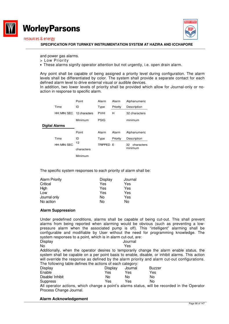
SPECIFICATION FOR TURNKEY INSTRUMENTATION SYSTEM AT HAZIRA AND ICCHAPORE
Page 98 of 147
and power gas alarms. > Low Pr ior i t y • These alarms signify operator attention but not urgently, i.e. open drain alarm. Any point shall be capable of being assigned a priority level during configuration. The alarm levels shall be differentiated by color. The system shall provide a separate contact for each defined alarm level to drive external visual or audible devices. In addition, two lower levels of priority shall be provided which allow for Journal-only or no-action in response to specific alarm.
The specific system responses to each priority of alarm shall be:
Alarm Priority Display Journal Critical Yes Yes High Yes Yes Low Yes Yes Journal only No Yes No action No No
Alarm Suppression
Under predefined conditions, alarms shall be capable of being cut-out. This shall prevent alarms from being reported when alarming would be obvious (such as preventing a low-pressure alarm when the associated pump is off). This “intelligent” alarming shall be configurable and modifiable by User without the need for programming knowledge. The system responses to a point, which is in alarm cut-out, are: Display Journal No Yes Additionally, when the operator desires to temporarily change the alarm enable status, the system shall be capable on a per point basis to enable, disable, or inhibit alarms. This action will override the response as defined by the alarm priority and alarm cut-out configurations. The following table defines the actions of each category: Display Display Journal Buzzer Enable Yes Yes Yes Disable/ Inhibit No No No Suppress Yes Yes No All operator actions, which change a point’s alarms status, will be recorded in the Operator Process Change Journal.
Alarm Acknowledgement
Point Alarm Alarm Alphanumeric
Time ID Type Priority Description
HH: MIN: SEC 12 characters PVHI H 32 characters
Minimum PSIG minimum
Digital Alarms
Point Alarm Alarm Alphanumeric
Time ID Type Priority Description
HH: MIN: SEC 12
characters
Minimum
TRIPPED E 32 characters minimum

SPECIFICATION FOR TURNKEY INSTRUMENTATION SYSTEM AT HAZIRA AND ICCHAPORE
Page 99 of 147
Acknowledgement of alarms shall be performed from the PLC operator station (HMI). Alarms shall be annunciated flashing to the operator. Upon acknowledgement, the flashing shall cease and alarms shall become steady. Alarm annunciation shall distinguish between alarm priority levels and shall comprise both audible and visual signals. Lower priority alarms shall not block higher priority alarms. Acknowledgement of alarms shall be possible per individual alarm. Multiple alarm acknowledgement capability for the different alarm priority levels shall be as follows: > Critical Priority : Not possible (only one alarm at a time). > High Priority & Low Priority : Shall be possible.
Alarm Summary
As a minimum, the following alarm summary information shall be displayed: Analogue Alarms The display shall also contain a readily visible means of distinguishing acknowledged from un-acknowledged alarms, e.g. blinking field. If an alarm returns to normal prior to being acknowledged, it shall remain on the screen with a unique identifying characteristic, e.g. reverse field. Upon being acknowledged, the alarm shall be removed from the screen. A minimum of thirty (30) alarms shall be displayed on each page, with a minimum of five pages available for display. The page number shall be displayed with the respective page. In addition, the total number of alarms in the summary shall be displayed on each page to assist the operator in quickly assessing the current alarm situation.
Dead band
All Analogue inputs shall have an assignable alarm dead band value. Before an input is defined as returned to normal the input must have returned into the normal operating range by the dead band value.
Alarm and Event Logging
All alarms (including suppressed alarms) and events shall be stored in a non-volatile memory. Facilities for the retrieval and search of this stored information shall be provided. Selection criteria shall include ‘alarms which occurred within a specified time interval’, specific alarm or event types, alarm priority level etc. The selected information shall be accessed via the HMI upon operator request. Alarms shall be time tagged on real time basis, in the PLC unit they originate with a resolution of at least 300msec. Critical and High priority alarms shall be presented on all HMI within 1 sec. Lower priority alarms shall not block higher priority alarms. Alarm handling is of vital importance. System configuration must ensure that operator response effectiveness is not jeopardized. There are two main areas of concern: > The risk that essential alarms are missed and not responded to effectively during alarm
avalanches > The risk that too much time is spent on alarm/event analysis. To minimize the risk, the
following requirements must be incorporated: > An alarm/event differentiation mechanism as defined below shall be used as a primary
tool to isolate the cause:

SPECIFICATION FOR TURNKEY INSTRUMENTATION SYSTEM AT HAZIRA AND ICCHAPORE
Page 100 of 147
Event: a change of status of a digital data item or the crossing of a predefined threshold value (in either direction) associated with an Analogue or totalizer data item. The digital, Analogue and totalizer data items may be real or derived.
Alarm: an event, which is brought to the attention of the operator by audible and/or visual means.
Alarms therefore form a subset of events. Events relate to status changes of an informative nature whereas alarms relate to status changes requiring operator attention and/or action.
> Changes to the alarm/event configuration shall be auditable as they can potentially affect the design integrity and safety of the station facilities.
> Suppressed alarms shall be identified > Ability to assess whether or not alarms have been acknowledged > Historical alarms/events shall be saved by exception > Alarm/event messages shall always included relevant, descriptive text, time and date of
occurrence.
Historical Database
All digital input and output status, control loop PV, set point, output and control mode and PID block tuning parameters shall be saved in the historical database based on minute, hourly, weekly and monthly average. The historical database shall be capable of collecting up to 100,000 samples per point and up to 500 derived and calculated Analogue values and 500 digital points. i) General The PLC shall have a historian which shall consist of the following : • Data collection engine • Storing, archiving and retrieval engine including data reduction engine • Presentation and reporting engine • Configuration engine ii) Data Collection The data collection engine shall be able to collect the following data classes : • Real t ime • Manual entr ies • User define data class The following types of data shall be supported : > integer (16, 32, signed, unsigned, packed) > Float ing point > Boolean > Character iii) Storing, archiving and retrieval The storing function shall include the necessary data compression facilities to conserve disk space. The archiving function shall include the necessary indexing facilities to allow fast and efficient data retrieval. The retrieval function shall include the necessary wildcard search facilities to mine for relevant data. It shall be possible to search the historian database on the basis of time, date, tag no., process description, critical level (for alarm), etc. The historian shall have built-in ODBC driver to allow interface to 3rd party system. Where required, this shall be available in real time basis. It shall be possible to transfer the historian HDD database to other bulk storage device(s) connected to the PLC to prevent valuable data from being overridden as the disk is used up. This operation shall be automatically done in the background without operator intervention. The basis for triggering the transfer operation to be firmed up during detailed design. The following reduction operations shall be supported: • average (hourly, shift, weekly, monthly) • maximum and minimum (hourly, shift, weekly, monthly) • sum (hourly, shift, weekly, monthly) • standard deviation (hourly, shift, weekly, monthly) • l inear izat ion

SPECIFICATION FOR TURNKEY INSTRUMENTATION SYSTEM AT HAZIRA AND ICCHAPORE
Page 101 of 147
iv) Presentation and reporting The presentation and reporting engine functions shall include: • Process parameters historical trending • Alarm and event history (for both process and system) • Operator action audit trail (for both process and system) • Reports and logs generation (in conjunction with the report generation software) The listed items above shall be translated into operation reports and logs. These shall be included in base proposal. v) Configuration It shall be possible to configure the historian online. It shall be possible to add / delete collection points or change collection point parameters or reassign reduction operation for a particular collection without stopping the historian. If the historian is from 3rd party, this should be embedded into the system such that the configuration is part of the system instead of having a separate dedicated historian configuration environment. For the bid purposes, the following shall be historised / logged: ~ Process related > All Analogue inputs > All Analogue outputs > All set points > All alarms and shutdown status > All status changes
> All process audit trial e.g. set point change, auto/manual changeover, local/remote selection These shall include all I/Os i.e. connect direct the PLC, via gateways, via OPC and relevant derived / calculated points i.e. standard flow and accumulated flow. ~ System related > Al l system alarms > Al l system status > System audit trial e.g. operator keystroke action, etc. All alarm and status changes (for both process and systems) shall have tag no., time and date stamp, service description and alarm level (for alarm only). vi) Sizing The historian module shall be sized to handle all of the above collection points plus 20% spare. The size of the historian HDD is dependent on no. of collection points, sampling frequency, reduction operations and data retention requirements. The requirements shall be finalized during detailed design. However, VENDOR shall allocate at least 80GB free HDD space for the historian as part of base bid proposal. The historical data in the PLC shall also be available in the database server. The data shall be updated on real-time basis. Reports shall be user configurable and on demand basis. The PLC shall allow unlimited permutations of operation/process/parameters access or blocking to suit individual access level requirement. The above are only guidelines for bid purposes. Details to be finalized during implementation. PLC shall have buffer memory for data storage during fiber optic communication failure. Data update and refresh functions shall be automatically synchronize between Stations PLC and SCADA systems upon communication reestablished. Buffer storage capability is the requirement of PLC of RTU.
4.7 Data Base Configuration
The Data Base Configuration shall provide a file-oriented structure for the purpose of data acquisition, data conversion, digital filtering, scaling, and high/low alarm limit checking. Process data point creation shall be conversational fill-in-the-blanks techniques for ease of use. Every input or calculated value shall have a unique point tag name of a minimum 12 characters. Each data point shall have a minimum 32-character descriptor using any combination of letters, numbers, and spaces.

SPECIFICATION FOR TURNKEY INSTRUMENTATION SYSTEM AT HAZIRA AND ICCHAPORE
Page 102 of 147
Engineering unit, range, and conversion parameters on a per point basis shall be provided. This includes all typical process inputs such as flow, pressure, thermocouples, RTD’s and contact I/O. Capability for assignment of different scan frequencies for each data point, ranging from 100 msec to 3600 seconds, shall be provided. The system shall also provide for exception reporting, with timeout selectable. All of the parameters and features noted above shall be individually selectable and modifiable in an on-line fashion at the operator station. Each data point shall have the capability of assuming various states. The state shall provide an indication of the condition of the hardware and software. As a minimum, the following stated should be provided: MANUAL :In this state, the data point is not being processed. Data values may be inserted by User BAD :This state shall indicate a software malfunction. The data point shall be returned to ON only by User initiation. STANDBY :This state shall indicate hardware malfunctions such as multiplexer failure, transmitter failure, open thermocouple detection, etc. In this state, the last reasonable data value shall be maintained in memory. When the hardware malfunction clears, the data point shall be automatically returned. The data point state shall be combined with the process alarm conditions to indicate data point status in a concise manner. Hardware and software malfunctions shall precede process alarms. For instance, if the data point state is BAD, its status shall also be BAD, irrespective of previous process alarm condition. However, if the data point is first monitored with a high alarm present, and subsequently BAD, its status shall remain HIGH but background color will indicate that it is bad. It shall be possible to build new data points, modify existing data points, and install the points in any applicable mode, without removing that node from service or affecting any existing points in the system. The same shall be true for removing points from the system. The database shall automatically be updated whenever a node is reconfigured to add or delete data points. The system shall determine and advise if a new point is being added and if the proposed new point is already in used in the system. The system shall have the ability to load/install multiple points from the load media to any applicable node on line, without affecting that node. It shall be possible to recover the configuration of a node and its database and store it on hard disk or removable media for later reloading. The database shall be designed to handle the number of I/O points (hard or soft points) including a 20% spare capacity. As a minimum, the database shall contain the following types of data: • All point tag names • All point parameters (e.g. engineering ranges, units, alarm set points, etc.) • All point groups • Field input/output data • System derived data • Trend data • Histor ical data • Graphic formats • Report formats • All diagnostic data • System configuration data • Other pertinent data All data whether it be field or system calculated, including system alarms and diagnostic information shall be globally accessible by every node on the highway.
VENDOR shall state any restrictions in the database in his bid proposal 4.8 Report Generation

SPECIFICATION FOR TURNKEY INSTRUMENTATION SYSTEM AT HAZIRA AND ICCHAPORE
Page 103 of 147
Report generation facilities shall be available on the system. VENDOR shall quote base on the assumption that 15 reports and logs to be configured. Detailed such type of report, I/Os to be configured for each report, report format/presentation, report retention time, report archiving and restoring shall be finalized during detailed design stage. The system shall be capable of generating printed reports of selected data on a periodic, event initiated or operator demand basis. Reports shall be of both standard and variable formats.
4.8.1 Standard Format Report
The standard format report shall be user configurable and will contain selected information from any log, event, or alarm list.
4.8.2 Variable Format Reports
The variable format report shall be user configurable with the ability to include any system data, such as data stored in historical trend files or controller inputs/outputs. It is required that manipulation and calculation be allowed to generate time-based averages, totalizations, minimum/maximum values and minimum/maximum times. It shall be possible to include other reports or logs in a given report. Variable format reports shall not require a programming background such as Basic, FORTRAN or some other language based software to set up.
Logs General
The system shall be capable of generating logs for a pre-specified set of point parameters. The log shall be selectable as to whether a snapshot (current value) or a set of average values is printed. The logs shall be schedulable for printout at any time before, on, or after the hour.
Logs Periodic
The system shall be capable of generating the following periodic log: hourly, shift, daily, monthly. The User shall be able to request more than one copy of any log. The data currently accumulated for these logs shall be protected in case of system failure. The system shall continue collecting data automatically on system restart.
Logs Event Driven
The system shall be capable of generating a log or report on occurrence of a pre-specified event. The system shall record certain events, which are pertinent to the process and the system. The events shall be categorized as follows: • Process Alarms • Operator Process Changes • Operator Messages • System Status Changes • System Error Messages • System Maintenance Messages The events shall be recallable for display or printing at the discretion of the User.
Printed Trends
The system shall be capable of printing continuous trends or trend history of a point(s) (up to eight at a time) over an operator specified time span. The data shall be available for reports. A

SPECIFICATION FOR TURNKEY INSTRUMENTATION SYSTEM AT HAZIRA AND ICCHAPORE
Page 104 of 147
common printer shall be provided for logging, utility and alarming purposes. Failure of any operator station electronics shall not affect the operation of any of the peripherals.
Printer Assignment
The Operator shall be able to direct logs, reports, etc. to the common printer assigned to his console.
Log displays
Any report, log, or journal shall be capable of being displayed on HMI at Operator’s discretion.
4.9 Audit Trail Electronic Audit Trail covering trend data and alarms/events is required for on and off plant investigation of causes and circumstances, which lead to the process upsets. The data recording is also required for normal operation events (i.e. pump start stop, open-close position of valves, transmitter re-calibration) and shutdown event. These will be recorded directly by PLC. Sequence of Event Recorder (SER) is to be provided to record all shutdown events. The recorded sequence of event data will be manage by PLC and accessible for display in PLC. The SER function should include post-incident investigation by the operator at the time of incident. Using ‘print-to-file’ (PTF) facility, the SER shall be accessible at Stations control room. For post mortem analysis, it is required at least one-day alarm/events and trend data leading up to, coincident with and just after the event is captured in an electronic file. The trend and sequence of event data should be made available off-line. The trend data shall also be used to dynamically reconstruct the circumstances and parameters values leading up to and coincident with the event.
4.10 Security
The PLC shall have the capability to check user commands for authorization. Access to all system functions shall be protected by a password application in combination with setting of physical switches. The operation software (i.e. Windows or equal) or latest version security application alone is not sufficient. VENDOR shall propose during detailed design the level of security beyond that applicable within operation software or latest version. The security application shall have the capability of limiting user access to the specific process control, operator interface, and system privileges that the user has been properly trained to use. The System Administrator privilege will be required to set up and change user accounts and access privileges. The security application shall have the capability to define user groups with predefined access privileges that can be tailored to fit user job classifications. Five (5) different levels of system access privileges shall be included for personnel use and to support the PLC. The access levels shall be under key lock or password control in combination of physical switch setting. The levels should be as follows: Level 1 - View Only > Monitoring only
> No data entry or process changes possible Level 2 - Operator Access
> Full control of process including shutdown system input bypass action (when enabled with dedicated group bypass key switch) > Control loop tuning • Alarm acknowledge and suppression capability

SPECIFICATION FOR TURNKEY INSTRUMENTATION SYSTEM AT HAZIRA AND ICCHAPORE
Page 105 of 147
• Control block auto/ manual mode selection and set point change. Level 3 - Supervisor Access > Full control of process including mode selection and set point change) > Alarm acknowledge and suppression capability > Modification of control graphics > Enabling output simulation Level 4 - Engineer Access > Full access to and interactive change capability of all system software > Full data base parameter modification capability > Full access to application software packages > Full access for configuration changes Level 5 - System Administrator Access
> Full access to everything including security feature management 4.11 Help Function
Help function shall be available and shall provide information on appropriate topics based on the current operation. Help shall be made available for all operations and shall be easily invoked using dedicated key, pointing, and selecting. The help information shall be displayed on the operator station in use. The operator shall also be able to select any other operator station on which to display the help information, in order to have a full, unhindered view of the current display. The operator shall be able to print out help information on selected printer.
The operator to return to the last operation shall easily terminate the help function. Facilities shall be provided to build or change help information text and displays.
4.12 Time Synchronization All alarm and event shall be time tagged with a resolution of minimum 300 msec. The time
tagging shall take place in the node that detects the alarm or event. In order to obtain module time compatibility, the system shall have a facility for synchronizing the clock in each node to precision sufficient to obtain the specified time discrimination between alarms and events originating from different nodes.
Every station PLC shall be time synchronized with the clock at Hazira and Icchapore. 4.13 System Response Time 4.13.1 Controller Scan Time (Cycle Time) This is the total time required for reading and processing the input, performing control
functions and updating the output for the final control element for all the loops connected to a particular controller. Refer to section 4.4.3.5 for scan time requirements.
4.13.2 Display Call up time
This is time elapsed between operator's command and appearance of the display on the screed with current dynamic data. This time shall not exceed one second including any custom graphic display.
4.13.3 Display Refresh rate
This is the rate at which the value of a particular input to the system gets updated on the HMI display. This shall include I/O points from foreign devices and shall apply to any display type including user-defined graphic displays. This rate shall not exceed one second.

SPECIFICATION FOR TURNKEY INSTRUMENTATION SYSTEM AT HAZIRA AND ICCHAPORE
Page 106 of 147
4.14 System Loading
The loading refers to the use of memory, CPU time and communication capacity. The loading shall consider worst case system activity.
A maximum loading of 50% is allowed for: > Control processors
> Memory > Communication Processors No degradation of system performance including response times shall take place at 60% loading. It shall be possible to monitor system loading via system status/diagnostic displays.
4.15 System Back-up
The entire control software including database, controller settings, software, source code, schematics, etc. shall have the option to automatically back up in the system hard disk at regular intervals. It shall also be possible to have a back up on demand. It shall be possible to have back-ups on CDROM. Any failed device of the system shall be capable of being reloaded from the backups. The controller memory (RAM) shall have a battery back up of 48 hours to save the controller configuration in case of power failure. VENDOR shall provide a list of all batteries used within the PLC, indicating battery type, rating, shelf life, and location within the PLC and renewal frequencies. Detailed testing and renewal procedure shall also be provided. VENDOR shall advise how the status of batteries is indicated. Immediately after SAT, VENDOR shall replace all batteries within the PLC.
4.16 System Testing and Diagnostics
The PLC shall incorporate extensive self-diagnostics, fault monitoring and fault diagnostics via continuous and periodic testing procedures automatically and upon operator initiation. The self- diagnostics shall be such that all transient and permanent faults are identified, alarmed and reported. Every node within the system must be under continuous surveillance by diagnostic programs. In the event of failure, the operator must be alerted at the HMI and at the location of the malfunctioning service. Self-testing shall be performed to ensure that the modules are capable of performing correctly prior to being put into operation and to monitor the performance during operation. Tests shall be performed on all modules whether primary or backup. The system shall be capable of monitoring all main processors, power supply modules, I/O modules and the communication highways. The following tests shall be regarded as the minimum requirement: > I/O Module fault monitoring. > I/O circuit operation verification. > Logic system self tests. > Power supply distribution monitoring. > Data storage availability and integrity tests. > Communication interface checks The VENDOR shall describe in his bid, all available tests in detail and how information will be presented to the operator upon detection of a fault. The system configuration and design shall be modular in construction utilizing plug-in modules. The removal of one such module shall not affect the overall system operation or associated circuits i.e. redundancy shall not be on the same card. Module replacement will be possible with the associated rack powered up and system operational. System diagnostics shall alarm a failure in the minimum of time and switch to the redundant unit automatically.

SPECIFICATION FOR TURNKEY INSTRUMENTATION SYSTEM AT HAZIRA AND ICCHAPORE
Page 107 of 147
Communication diagnostics should include tabulations showing communications statistics and type of failures, updated in real time i.e. (framing errors, parity, CRC, timeout etc.). System diagnostics shall have an error reporting and indicating structure that make use of HMI diagnostic displays and LED status indicators to indicate status of hardware. System diagnostics shall prevent communication errors from upsetting the process. Testing and fault monitoring shall not in any way affect the normal operations of the protective systems. Automatic testing shall not disable the correct executive actions from taking place. A malfunction in the testing and monitoring facilities shall not degrade the operation of the system. All detected faults shall be indicated in the PLC. General fault status shall be via the HMI. The detailed fault diagnostics and system self test reports shall be available to the operator on any of the Workstation (HMI and EWS). PLC shall incorporate facilities for remote diagnostics and trouble shooting from anywhere via SCADA System through fiber optic communication. Access shall be controlled to prevent unauthorized access. VENDOR shall provide details of his standard diagnostic package in his bid. VENDOR shall explicitly detail in his bid, all types of faults, which may not be detected by his proposed / implemented diagnostics and self test and shall proposed measures or procedures to overcome this problem. VENDOR shall describe in his bid and include any equipment, which is required for implementing his proposed testing philosophy in his bid.
4.17 Engineering Work Station (EWS) for PLC
One (1) unit of Engineering Work Station (laptop) shall be provided. It serves two main purposes. The first is to provide on-site process control and display. The second is to serve as a configuration tool for operator to reconfigure the PLC. The Graphical User Interface (GUI) / Human Machine Interface (HMI) software shall be the GUI/HMI supported by the PLC hardware. It shall be the latest proven version and has been used in oil and gas application for a minimum of 4000 hrs. VENDOR shall submit detail description of software including all function capabilities during bid. EWS shall enable the following functions to be performed: > Configure and commission the PLC. > Download a modified configuration into the PLC. > Perform diagnostic testing of the PLC. > Download and diagnostic data from the PLC > Printing of software, I/O listing, I/O cross-reference list, etc. > Online documentation (self-documentation) of the PLC as per VDRL. > Offline simulation of control schemes. The EWS shall be supplied with the operating system software in the English Language. The EWS and PLC shall be functionally independent. A failure or power off in one system shall not affect the other. VENDOR shall also supply the interconnecting cables between the PLC and the EWS Workstation and the power supply units for use on 230 VAC 50 Hz. The Engineer shall be able to (by password access) take the following actions through the alphanumeric keyboard: > Change data base configuration > Change alarm PV settings > Inhibit alarms during plant maintenance > Change graphic displays > Change clock settings > Access file management facilities It shall be possible to view a variety of system information from the EWS, including the topology for the network and statistics concerning the performance of the network. It shall also be possible to run on-line and off-line diagnostics and perform off-line simulation. As a process control and display device, the following basic functions shall be provided, as a minimum: > Graphical, text and character-based dynamic displays

SPECIFICATION FOR TURNKEY INSTRUMENTATION SYSTEM AT HAZIRA AND ICCHAPORE
Page 108 of 147
> Displays shall be configured which includes:- > Overall Station Status (Station Critical Data Information) > MOS Bypass Status > Unit Control System for Mainline Pumps > Graphics and Animation as per the P&IDs > Monitor all I/O Points > Monitor all PID loops > Display/Save Historical Database > Display / Save Alarm and Event Log As a configuration tool, the following basic functions shall be provided, as a minimum:- > Configure and manipulate (e.g. force on/off) all type of I/O point, PID block, Flow
Calculation Block, Communications Port etc. > Auto tuning of PID blocks. > Programming of customized application program > Basic file operations such as save, load, print of configuration setup. The following
specific function shall also be provided: > Manipulation of PID block by external signal (e.g. during PSD, the PSD shall force the
PID block to be put to manual, and the output be ramp down to 0%) Analogue values. Difference in valves outside a preset values shall be alarmed. The display speed of response shall be two seconds maximum from the time a button is pushed until all real-time information is completely updated and displayed. The template or background information shall appear almost instantly with real-time information filled in as the database is scanned. Time of day and date shall appear on any display to indicate that the EWS display is constantly being updated.
4.17.1 PLC Training
PLC Training shall be include following topics
Background to the PLC:- The PLC in Industry PLC Technology and Electronics PLC Communication Terms PLC Protocols Communication & Electronics Networking standards
How to Write Programs using:- Contacts & Coils Timers and creating delays, cascading timers. Latches and where to use them. Single Shot Pulse Starting and Stopping a Process Control Data handling, Store and Move data How to use PLC Instructions in your programs Using Binary/Hex/BCD
Programming: The PLC Scan Learn how to use a Support Tool Support Tool Manual included free. Addressing structures Programming a CPM Series PLC

SPECIFICATION FOR TURNKEY INSTRUMENTATION SYSTEM AT HAZIRA AND ICCHAPORE
Page 109 of 147
Addressing your programs Using PLC numbering Binary/Hex/BCD IEC 61131 standard Instruction List programming Commenting Programs Program Symbols PLC Scan and execution times Process Control Programming How to create a process program - Incorporate alarms, interlocking, safety etc. As used in chemical, oil, water, food & drink, plastics industries.
Force & Set Program Layout to Industrial Standards Alarm Handling Introduction to Safe Programming Techniques Structured Programming Fault Finding Creating speed/temperature controller How to create Industrial standard programs
Introduction to PLC Communications: Profibus/CAN/DeviceNet RS485 RS485 and 232 differences Ring & Star topology
Hardware: Control/Addr/Data Bus IO Card Wiring Wiring layout Addressing & Special IO
How to Write Programs using: Latches and where & where not to use them. Single Shot Pulse Counters Inc/Dec data Using Conditional Instructions Creating Process Alarms Alarm Handling Status Routines Starting and Stopping a Process Interlocking
4.17.2 PLC Status and Diagnostic Display
The following diagnostic status shall be provided, as a minimum: > Integrity check > Individual card failure > Power supply under voltage and over voltage error > All communication failures The diagnostic display shall give a complete description of the malfunction. The procedure to correct the problem shall be straightforward and clearly stated in diagnostic manual/dictionary. All
SPECIFICATION FOR TURNKEY INSTRUMENTATION SYSTEM AT HAZIRA AND ICCHAPORE
Page 110 of 147
changes in system status must be automatically logged in the PLC Alarm Log indicating date, time, change in status and diagnostic information.
4.17.3 Stand Alone Alarm Monitoring
Alarm monitoring facilities shall be contained in the EWS and shall be capable of being enabled or disabled on-line. The facilities shall be stand-alone and shall use a separate PLC database. Alarms on both Analogue and digital points shall be provided for and shall be inhabitable on an individual point basis. All alarms shall be time-stamped. The EWS is permanently connected to the PLC and shall have a minimum of three alarm priority levels, which shall be differentiated by colors. A common PC-generated system audible alarm tones for all priority levels is acceptable. Control functions on the PLC shall not be slowed down or suspended during an alarm burst (and subsequent heavy data traffic between the PLC and EWS) when an emergency or shutdown occurs. All events involving both Analogue and digital points shall be configurable to be logged in PLC Standard built-in Event Log. A time stamp shall be provided.
4.19 Maintenance Override Switch (MOS)
Maintenance override switch (MOS) is used to override ESD initiators to enable maintenance or on line functional testing. Logic in ESD shall check that a maximum of one trip initiator maybe overridden per protection group at any one time. MOS function shall not inhibit the alarm function. Maintenance override Enables (MOS-ENA) hardwired key-switches (contact close to enable) shall be provided on the Annunciator Panel to provide a hardwired enabled signal direct to the ESD. The following MOS–ENA key switches shall be provided on the Annunciator Panel: > Station Process area A yellow, common for MOS-ENA, hardwired MOS indication lamp driven from the ESD shall be provided on the Annunciator Panel to indicate that at least one override is set in the relevant process unit. The MOS-ENA and MOS-IND status shall be read and displayed on the HMI. Time stamp of activation, removal, MOS-IND, and MOS-ENA. A dedicate overview graphic shall be provided on the MMI to enable operator to quickly find trip initiators in override. If the MOS function is not removed, low priority alarm shall be repeated every 4 hours; the state of the override shall not be affected however.
MOS shall not be applied for the following: > manual ESD, PSD
> reset pushbuttons, key switches > a l l outputs Soft-overrides switches with similar functions as above shall also be considered during detail design.
4.20 Operator Pushbutton Station (OPS)
All pushbuttons, key-switches and lamps shall be pre-wired to the rear of the OPS panel terminal strips. Items for shutdown shall be pre-wired to one terminal strip for connection to the PLC. VENDOR is responsible to supply and install the Operator Pushbutton Station.
4.21 System Interfaces

SPECIFICATION FOR TURNKEY INSTRUMENTATION SYSTEM AT HAZIRA AND ICCHAPORE
Page 111 of 147
The PLC HMI at Station Control Room shall be the primary operations window for the respective station. The PLC will be extended communications link for remote monitoring and control by SCADA system at other terminals.
4.21.1 Interface to Package Equipment
Transfer of data between the Package Equipment and the PLC shall be via Ethernet (TCP/IP 10 Base T) or MODBUS communications. The final link inter connect type will be confirmed after the selection of the package equipment. Package equipment at the field will be terminated at field junction boxes and wired to the instrument equipment room by station VENDOR. The following interfaces are envisaged at the station facilities as minimum:
1. Metering System 2. Switchgear and MCC Control PLC 3. Tank Farm Management System 4. Fire Alarm System 5. Gas Monitoring System 6. UPS 7. Other Sub Package Equipment Systems
VENDOR shall terminate cables inside the instrument room at the station. The package equipment shall supply a back-up Engineering Station (i.e. laptop) for emergency purpose.
4.22 System Cables
All multi-conductors System Cables required to interconnect the PLC chassis to the ELCO boards, if any, must be pre-fabricated with plug-in receptacles at each end and shall be supplied by SUPPLIER/VENDOR. System cables shall be adequately sized for minimum voltage drops. All multi-conductor System Cables required to interconnect the PLC System Cabinets and the Marshalling Cabinets if any, must be pre-fabricated with plug-in receptacles at each end and supplied by VENDOR. The exact lengths of these cables will be confirmed during detailed design based on the location of PLC System Cabinets and Marshalling Cabinets. System Cables within the same room are not required to be armored. System cable connectors shall have gold plated contacts/pins. System cables shall be single run continuous without mid line jointing or plugs. Analogue and digital signals shall not be run in the same cable. Also powered outputs shall be run in separate system cables and shall be adequately sized for minimum voltage drops. Special attention shall be paid to easy accessibility and withdrawal of the interface cables. The system cables shall be coiled and protected during the transportation and installation.
4.23 Uninterruptible Power Supply (UPS)
All PLC equipment shall be powered from the UPS system supplied by others at Station Control buildings at Hazira and Icchapore. VENDOR shall interface with Stations VENDOR to determine the UPS requirement for all supplied equipment. Surge protection device (SPD) shall be provided for the following circuits.
• Incoming feeders (UPS / raw) to PDB and to remote I/O rack. • From GPS antenna to GPS module.
Surge protection devices shall be from reputed manufactures like OBO, DHEN, and EMERSON.

SPECIFICATION FOR TURNKEY INSTRUMENTATION SYSTEM AT HAZIRA AND ICCHAPORE
Page 112 of 147
5.0 PANEL ENCLOSURE (CABINET) AND ELECTRICAL REQUIREMENTS 5.1 Panel Enclosure Requirements
All control equipment shall be installed inside the cabinets. The dimensions of the cabinets shall meet the requirements below as minimum (where applicable): a) Dimension: 800mm (L) x 800 mm (D) x 2 100mm (H) b) Dimension: 600mm (L) x 600 mm (D) x 2 100mm (H) All cabinets shall be fitted with integral plinth (100 mm) for door clearance and to facilitate installation. All the cabinets shall be Rittal or equivalent make. The sheet thickness of cabinets shall be minimum 2mm. The enclosure shall be minimum IP 42 to IEC 60529. The enclosure together with its internal electronics and wiring accessories shall be designed for safe area application. The cabinet shall be free standing with front and back access. The securing of enclosure cover shall use stainless steel screw clamp fastener such that none of the fastener parts can fall off or go missing. All cabinet doors shall have lift-off hinges and be lockable with identical keys. The opening angle of the doors shall be at least 135 degrees. Dust filters shall be of the replaceable or cleanable type and this action shall be possible without disturbing the functions of the cabinet. VENDOR shall provide, in the bid proposal, the heat load calculation based on the worst- case condition i.e. all loads energized, at the maximum ambient temperature. The maximum outside temperature of the enclosure shall not exceed 50°C All enclosures shall have a temperature switch mounted in each enclosure to sense the inside temperature of the enclosure. This temperature switch shall be counted as one digital input to the PLC and shall trigger an alarm when activated. Wiring inside the enclosure shall be within the cable trays. Cables shall be individually tagged and neat. All wiring inside the cabinet shall have 30% spare for future expansions. The enclosure shall be provided with external grounding lug and nut/bolt for connection to facility grounding system (to be provided by others) Each enclosure and all major system components, card files and individual card locations shall be clearly labeled and identified. Nameplates shall be in the English language. In addition, all equipment shall be identified with the SUPPLIER/VENDOR type and serial number to facilitate future reference. Any unused card slot shall be fitted with suitable dummy card. Labeling must not be installed on devices that can be removed. Static electricity discharge wrist straps to be provided on all panels.
VENDOR shall provide drawing pocket in the enclosure. Tentative number of panels to be supplied by vendor:
CABINETS Hazira Icchapore W X D X H PDB + Marshalling 01 01 800 x 800 x 2200
PLC CONTROLLER 01 01 1200 x 800 x 2200
6.0 INSPECTION AND TESTING REQUIREMENTS Scope
VENDOR shall be responsible for the integration, inspection and testing of the control systems. VENDOR shall assume final responsibility for the inspection and testing of the

SPECIFICATION FOR TURNKEY INSTRUMENTATION SYSTEM AT HAZIRA AND ICCHAPORE
Page 113 of 147
control systems to ensure that the system conform to the requirements of the codes and standards specified in this document. COMPANY may appoint a third party inspection services for the control systems. The COMPANY’S representative shall have free access to VENDOR’S facility and those of all major SUPPLIER/VENDOR’S facility at all times. Inspection by COMPANY or his Inspector will in no way relieve VENDOR of any of his responsibilities for ensuring that the system supplied meets all the requirements of this document and its attachments. Inspection and testing shall be carried out at the SUPPLIER/Vendor’s work place and shall be witnessed by COMPANY’S representative. Based on this document, VENDOR shall submit full testing procedure for factory testing, site testing and acceptance procedure for COMPANY’S approval. For hardware, the procedures shall include purpose of test, test definition of input, procedure, result expected, and acceptance criteria. For software, it shall include details of the method, list of tests, sequence of execution, result expected, and acceptance criteria. The testing and acceptance of the system shall be carried out on the mutually agreed procedures and criteria based on this specification and SUPPLIER/Vendor’s standard procedures. VENDOR shall identify in the project schedule hold points for COMPANY witnessed inspection/ test.
Factory Acceptance Test (FAT)
The FAT shall be a thorough and complete functional test of the hardware and software of the entire control system. FAT procedures shall be submitted to COMPANY for review and approval. VENDOR shall conduct inspection after completion of all work, including equipment burn-in and pre-FAT test performed as appropriate. Pre-FAT test report shall be submitted to the COMPANY prior to FAT. VENDOR shall give COMPANY advance notice of at least fifteen (15) working days before the FAT is conducted. VENDOR shall demonstrate the functional integrity of the system hardware and software. No material or equipment shall be transported until all required tests are successfully completed and certified ‘Ready for Delivery’ by the COMPANY. COMPANY reserves the right to be involved and satisfy himself at every stage of inspection. COMPANY shall be free to request any specific test on any equipment considered necessary by him although not listed in this specification. VENDOR shall note that acceptance of any equipment or the exemption of inspection or testing shall in no way absolve VENDOR of the responsibility for delivering the equipment, which meets all the requirements specified in the specification. The FAT shall be conducted CONTRACOR’S manufacturing facility. VENDOR shall provide a room, complete with acceptable office facilities and refreshments for the COMPANY’S representative(s) for the duration of the FAT. All equipment (including the shutdown functions) shall be tested together as a system complete with all operating controls. All tests shall be conducted utilizing only equipment that will eventually be shipped to the COMPANY. Use of “replacement” units during any part of the FAT will not be allowed. Any defects found during the FAT shall be rectified in the presence of the COMPANY. In the event this is not possible, a checklist shall be prepared stating all outstanding items for approval by the COMPANY’S Inspector. It shall be VENDOR’S responsibility to modify and/or replace any hardware and modify the software if the specified functions are not satisfactorily achieved during testing and factory acceptance. The equipment shall not be shipped until all discovered defects have been rectified and satisfactorily re-tested. The following test shall be included into the FAT as a minimum: a) Power Supply tests b) Processor tests

SPECIFICATION FOR TURNKEY INSTRUMENTATION SYSTEM AT HAZIRA AND ICCHAPORE
Page 114 of 147
c) I /O tes ts d) Funct ional tests e) All communication interfaces f ) Electrical noise immunity g) Radio Frequency Interference h) Dimensional checks i) Optional Heat Soak test (a separate cost is to be provided for this) as specified below: > Heat Soak Test duration shall be 100 hours. > Ambient temperature shall be simulated at 35°C. > The temperature shall be increased to 50°C (15°C above ambient) for 12 hours cycle between ambient and 50°C. > Full load shall be maintained as practically feasible throughout the test. The factory inspection shall be carried out as follows: a) VENDOR shall perform in-house testing prior to COMPANY witnessed FAT to assure smooth testing during the FAT. b) VENDOR shall then systematically, fully, and functionally test all the hardware and software in the presence of COMPANY’S representative/inspector. All systems shall be interconnected to simulate, as close as possible, the total integrated system. VENDOR shall use a simulator suitable for all types of I/O. Individual system I/O shall be able to be tested with the simulator, with related checks being made on interactions between other parts of the system. Apart from visual and mechanical testing, functional testing shall include the simulation of each input and output to verify proper system response for both analogue and discrete signals. All hardwired inputs and outputs shall be wired to simulator panel prior to FAT. The testing as a minimum shall include: a) Check of all input/output points. b) Check of scans time values. c) Check of all control configurations as to input, output, modes, failure, action, etc. d) Check of loop configuration as to ranges, limits, alarm points, unit etc. e) Check of all computations. f) Check of all logic and sequence control. g) Check of correct changeover of the back-up units. h) Check of keyboard/touch screen functions, key-lock functions. i) Check of log reports and historical functions. j) Check of all displays. k) Check of HMI refresh rates, data base update and display call-up time. l) Check of module diagnostics. m) Check of remote diagnostics via. n) Power failure o) Communicat ion failure p) Electrical noise immunity q) RFI immunity r) Communication between SCADA/PLC/RTU and Subsystems s) Serial link communications to other package equipment All hardware must be inspected for physically damaged components and general workmanship standards. Particular note should be made of: a) Wiring looms and terminations b) Quality of earth and power connections c) Ease of access for maintenance work. d) Door seals and paint finish with reference to the final site environmental conditions.

SPECIFICATION FOR TURNKEY INSTRUMENTATION SYSTEM AT HAZIRA AND ICCHAPORE
Page 115 of 147
e) Printed circuit board connections to backplanes in card cages f) Plug and socket connections. g) Robustness of supports, frames, and circuit boards A number of tests must be carried out on the completed system. The following tests are a minimum requirement and shall be carried out on the total deliverable system hardware and software, including commissioning spares. The system shall be fully configured to provide all functions as detailed in the Specification. Any external system interfaces must be adequately simulated by VENDOR equipment. Shock Test and Vibration Test During this inspection, a simple shock vibration test shall be carried out on a number of plugs, sockets, terminal blocks, and printed circuit board backplane connections to ensure that a reliable and secure connection is provided. The shock test shall be performed on an operational system by tapping the aforementioned components with an insulated device. Care shall be exercised so as not to damage the equipment. Any abnormal effect of the system shall be investigated and rectified be VENDOR. Supply Power Variations This test shall be conducted to verify the ability of the system to compensate for input power variations without impairment of system performance. The following power variations shall be applied on an operational system for a minimum of 20 minutes each. System functional performance shall be monitored for abnormalities at the system displays sand indicators: a) Maximum specified voltage and nominal frequency. b) Minimum specified voltage and nominal frequency. c) Maximum specified frequency and nominal voltage. d) Minimum specified frequency and nominal voltage. e) Input power interruption with nominal voltage and frequency before and after interruption. Radio Interference Test The following test shall be carried out to demonstrate the immunity of the equipment to radio frequency interference. A portable radio, of frequency and power to be agreed, shall be operated a distance of one (1) meter from each equipment cabinet or console in turn. All doors on the equipment cabinets or consoles shall be left fully open for the duration of this test. During the test, the system shall be operational and shall be monitored for abnormal indications or spurious data. Functional Test Functional testing is largely dependent on individual system requirements. The system shall be subjected to tests sufficient to determine its compliance with all functional requirements specified in this Specification. The following tests shall be performed, where applicable: a) Operator Interfaces 1. All specified operator commands, including data entry, cold and warm starts, changeovers; display and printout requests shall be exercised. The response to all commands shall be verified to be correct and within the specified response times. 2. Particular attention should be paid to commands under restricted access by means of key locks or passwords. The specified security access level shall be verified for all commands. 3. Where applicable, alarm annunciation facilities shall be exercised and operator’s silence and acknowledge commands shall be tested. The response time to alarm conditions shall be
SPECIFICATION FOR TURNKEY INSTRUMENTATION SYSTEM AT HAZIRA AND ICCHAPORE
Page 116 of 147
verified against that specified in this Specification. 4. All operator and system displays shall be demanded and examined for compliance with the Specification. Where displays are accessible be various routes, all such routes shall be tested and display cross references and indices shall be checked. b) Maintenance and Calibration 1. Procedures specified by SUPPLIER/VENDOR in the maintenance manual(s) for maintenance and calibration of equipment shall be carried out to ensure that all specified adjustments and other maintenance work could be conducted in a safe and reliable manner. c) Subsystem Compatibility Disks/Cassette Devices
System employing removable disks or cassettes for long-term data storage and archiving shall be tested for compatibility as follows: > Save data to a disk/cassette at one drive unit. > Restore data from the disk/cassette to primary memory at every other disk/cassette drive in the system. Repeat the above tasks by saving data at each disk/cassette device in turn. Printed Circuit Boards Where printed circuit boards are common to a number of sub-systems, repeat the following for each circuit board type: Remove one circuit board from a sub-system selected at random by the COMPANY. > Adjusts links or jumpers as necessary. > Insert the circuit board in another sub-system selected at random by the COMPANY. > Verify that the system continues to operate satisfactorily. The above tests for sub-system compatibility are a minimum requirement. Similar tests should be carried out on other common sub-systems, where applicable. Electrical Test
The following test shall be performed on all electrical and electronic modules and systems: > Functional test of all electronic modules, test for short circuits, and test for ground faults.
> Verification that terminal and wiring coding is in accordance with the panel drawings.
Subsystem Failures
Tests shall be carried out in order to verify that redundant systems operate as specified, i.e. changeover to back-up occurs correctly and is annunciated to the operator. Operator displays and diagnostics identifying the particular failed sub-system shall be checked as sufficient. The following redundant sub-systems are typical. a) Redundant Processors Failures on each processor (including back-ups) in turn shall be simulated. Failures should be simulated:

SPECIFICATION FOR TURNKEY INSTRUMENTATION SYSTEM AT HAZIRA AND ICCHAPORE
Page 117 of 147
> By interruption of the processor power supply for sufficient duration to cause a processor reset condition. > By manual reset of the processor > By inserting errors into PROM and RAM memory areas b) Redundant Power Supplies Failures on each power supply in turn, within a redundant system shall be simulated by isolating the supply. Functional performance of the system shall be verified as satisfactory with the minimum number of redundant power supplies in operation. Where battery back-up supplies are employed, the primary supply shall be completely isolated and correct operation of the battery supply shall be verified. This test shall be carried out on both system battery supplies and memory retention batteries. c) Degraded Operat ions The capability of systems providing reduced operations following particular subsystem failures shall be tested. Degraded system operations shall be verified as meeting project requirements. d) System Diagnost ics All standard system diagnostics provided by VENDOR shall be performed including both resident and non-resident diagnostic software. Typical diagnostics include: > Memory tests > Communications tests > Disk/cassette tests > Printout tests > Display character tests Where practicable, faults shall be simulated to verify correct diagnosis and monitoring by system diagnostic routines. Input/Output Simulation Test All inputs and outputs shall be simulated by VENDOR’S equipment. Correct indication of these inputs and outputs shall be verified together with all relevant configuration and logical or numerical calculation details within the database. The test facilities shall allow full load tests to be carried out, i.e. all inputs and all outputs simultaneously in their active states. Any item of equipment, including all software, hardware, and documentation, deemed to be unsatisfactory by the COMPANY and any test failure on the system or sub-system shall be rectified by VENDOR, at his own expense, and shall be re-tested to the satisfaction of the COMPANY.
Composite Instrument System Test (CIST)
Vendor’s responsibility includes the full scope of the CIST of the PLC system. The locations of the CIST shall be at Vendor’s works. The VENDOR shall carry out the CIST to check proper interfacing and interactions between the various systems, databases, and software. VENDOR shall be responsible for the entire CIST scope. An outline of the scope of this assistance is provided below: The CIST shall as a minimum include the following: > Review of test procedures

SPECIFICATION FOR TURNKEY INSTRUMENTATION SYSTEM AT HAZIRA AND ICCHAPORE
Page 118 of 147
> Relocation of the third party equipment to the CIST site (if required) > Connection of foreign devices > Energisation and system check out > Assistance with authorized changes to configuration > Maintaining system configuration backups > De-energisation of the system VENDOR shall provide personnel, as required, to perform the CIST. VENDOR shall be responsible for any repair or maintenance work required on the Control Systems during the CIST in accordance with the warranty agreement. Any problems encountered during CIST will be carefully recorded and corrected by the relevant individual equipment SUPPLIER/VENDOR to the satisfaction of the COMPANY. However, it remains Vendor ’s responsib i l i ty to l ia ise with the indiv idual equipment SUPPLIER/VENDOR to ensure the desired result is achieved.
Site Acceptance Test (SAT)
SAT shall be performed at each location of the facility at site during hook-up and commissioning. VENDOR shall be responsible for and shall provide the technical work force necessary for the supervision of the tie-in connections of the power cables for the system equipment, serial link cables, and the system cables to the cabinets. However, VENDOR shall be responsible for the supply of special tools and all wiring (i.e. supply, install and terminate) within the Control Systems equipment. VENDOR shall provide test kit to allow complete testing of system per module. VENDOR shall be responsible for the correct installation and hook-up of the complete equipment. VENDOR shall then load the system and application software and shall demonstrate the system functionality to verify system conformance with the requirements to the satisfaction of COMPANY. COMPANY shall reserve the right to instruct VENDOR to carry out a repeat of any or all of the tests performed during FAT. After completion of SAT, 21-days of trial period shall be conducted. Vendor’s engineer shall be present. If any fault occurs, the 21-days period shall commence again till the satisfaction of the client. After successful completion of trial-period, warranty period of 36-months shall be commenced. During that period, in each quarter, vendor’s engineer shall visit each station and spend 3 days at each station and shall resolve the problems, shall also carry out logic modification as required by operations group. Vendor shall attend any no. of break-down calls during that period.
Test Documentation
VENDOR shall supply a full set of deliverable documentation before the start of FAT. As a minimum, the following shall be supplied: a) The Specification and relevant drawings b) Draft set of operator and maintenance manuals c) Test Plan and Test Specification for factory acceptance tests d) Summaries of all previous testing including SUPPLIER/VENDOR tests The usefulness and purpose of documents shall be major consideration. For example, the operating manual must include clear and concise instructions for the typical plant operator, while technical manuals shall be detailed, complete, and accurate. Modifications carried out during the test period shall be detailed appropriately in the documentation.

SPECIFICATION FOR TURNKEY INSTRUMENTATION SYSTEM AT HAZIRA AND ICCHAPORE
Page 119 of 147
7.0 SPARE PARTS AND SPECIAL TOOLS
VENDOR shall include in the proposal, separate and individually priced the following categories of spare parts and tools. a) Start-up and Commissioning spares b) Two-year operational spares c) Capital spares d) Special tools and equipments Start-up spares shall include all items required during start-up and commissioning period. Items such as fuses, galvanic isolators, isolators, lamps etc. shall be included. Operational spares shall take into account related factors of equipment reliability, effect of equipment downtime on production and safety, cost of parts, and availability of service facilities. COMPANY shall be continuously informed of the new upgrades/versions of software, hardware, and firmware. VENDOR shall guarantee that spare parts for the system shall be available for a minimum of fifteen years. After this period, if SUPPLIER/VENDOR discontinues the production of spare parts, SUPPLIER/VENDOR shall give at least twenty-four months notice prior to such discontinuation so that COMPANY may order his requirements of spares in one lot. All spare parts furnished by VENDOR shall be wrapped and packaged so that they will be preserved in original, as-new condition under normal conditions of storage and shall be properly tagged and coded so that later identification as to intended equipment usage will be facilitated. They shall be packaged separately, clearly marked as “Spare Parts.” Packing lists shall be furnished so that the parts can be handled without uncrating if desired. The operational spares shall be categorized into the following: a) Consumable I tems Normal wear and tear items required for routine preventive maintenance. Delivery to commence on receipt of order and completed within 30 days. b) Crit ical Items These items are critical to the operation of the equipment. Failure will cause the unit to be out of commission. Delivery to commence in five (5) days and completed in fifteen (15) days on receipt of order. c) Non-Crit ical I tems The failure of these items reduces some function or eliminates a safety system, but they will not cause the entire unit to be out of service. Delivery will commence in five (5) days and completed in thirty (30) days on receipt of order. d) Non-Stock/Long Lead Items These items are available at full factory lead-time only. e) Repair Kits/Replacement Components Items listed are repair kits or replacement components for item (c) and (d). Delivery to commence in five (5) days and completed in thirty (30) days on receipt of order. Vendor shall supply the mandatory spares 5% PLC modules as mandatory spares and/or minimum one module of each type, for all types of cards/modules used on their system including I/O card, process card, memory, power supply module, communication card, power supply unit for interrogation. Mandatory spares shall not include hardware for workstations. Engineering spares/spares for future:
• 25% spares for I/O modules, intrinsic safety barriers, isolators, TB, relays etc. as

SPECIFICATION FOR TURNKEY INSTRUMENTATION SYSTEM AT HAZIRA AND ICCHAPORE
Page 120 of 147
installed and wired as engineering spares (control room wise) • 20% spare space for future I/O module, space in cabinets, marshalling cabinets, control
panels, TIC cabinet, space for intrinsic safety barrier, isolator, TB, relays, PB, selector switches etc. space for future cables for internal wiring.
8.0 DOCUMENTATION
All documentation for a complete Control System shall comply with the project requirements. VENDOR shall submit technical documents particularly drawings and specifications in a grouped, orderly fashion for review, acceptance, and installation. Groups of drawings shall be submitted together. English language shall be used exclusively. Multilingual markings, instructions, inscriptions etc are NOT acceptable.
9.0 NOTES TO VENDOR
1. Vendor to provide Layouts / Drawings (i.e. P & ID’s & Equipment Layout) for Hazira and Icchapore control rooms. Equipment layout shall be inclusive of Third Party Equipment & sub vendor Equipments. Worley Parsons shall approve P & ID & Equipment Layouts. Vendor to provide as built drawings for approval.
2. Data and drawings submitted by vendor shall be treated as indicative only, final
documentation shall on subsequent revisions & as built.

SPECIFICATION FOR TURNKEY INSTRUMENTATION SYSTEM AT HAZIRA AND ICCHAPORE
Page 121 of 147
SOR for Turnkey Instrumentation Systems at HPCL Hazira & Icchapore
Sr. No. Description UOM Quantity
1
Design, engineering, procurement, inspection, supply, testing, installation, commissioning, FAT and SAT of Station PLC System at ONGC Hazira as per specification no. 0435-JH0911-00-IN-SPC-0002 lot 1
2
Design, engineering, procurement, inspection, supply, testing, installation, commissioning, FAT and SAT of Station PLC System at HPCL Icchapore as per specification no. 0435-JH0911-00-IN-SPC-0002 lot 1
3
Design, engineering, procurement, inspection, supply, testing, installation and commissioning of Pressure Transmitters as per attached datasheet no. 0435-JH0911-00-IN-DAS-0104 each 23
4
Design, engineering, procurement, inspection, supply, testing, installation and commissioning of temperature transmitter as per attached datasheet no. 0435-JH0911-00-IN-DAS-0107 each 2
5
Design, engineering, procurement, inspection, supply, testing, installation and commissioning of flow transmitter as per attached datasheet no. 0435-JH0911-00-IN-DAS-0102 each 2
6
Design, engineering, procurement, inspection, supply, testing, installation and commissioning of flow elements (orifice type) as per attached datasheet no. 0435-JH0911-00-IN-DAS-0101 corresponding to flow transmitters in Sr. No. 5 of SOR. each 2
7
Design, engineering, procurement, inspection, supply, testing, installation and commissioning of temperature element as per attached datasheet no. 0435-JH0911-00-IN-DAS-0105 corresponding to temperature transmitters in Sr. No. 4 of SOR. each 5
8
Design, engineering, procurement, inspection, supply, testing, installation and commissioning of differential pressure gauge as per attached datasheet no. 0435-JH0911-00-IN-DAS-0100 each 2
9
Design, engineering, procurement, inspection, supply, testing, installation and commissioning of pressure gauge as per attached datasheet no. 0435-JH0911-00-IN-DAS-0103 each 25
10
Design, engineering, procurement, inspection, supply, testing, installation and commissioning of TSVs as per attached datasheet no. 0435-JH0911-00-IN-DAS-0106 each 15

SPECIFICATION FOR TURNKEY INSTRUMENTATION SYSTEM AT HAZIRA AND ICCHAPORE
Page 122 of 147
11
Design, engineering, procurement, inspection, supply, testing, installation and commissioning of control valves of size 4" and below as per attached datasheet no. 0435-JH0911-00-IN-DAS-0108 each 2
12
Design, engineering, procurement, inspection, supply, testing, installation and commissioning of control valves of size above 4" as per attached datasheet no. 0435-JH0911-00-IN-DAS-0108 each 1
13
Design, engineering, procurement, inspection, supply, testing, installation and commissioning of shutdown valve as per attached datasheet no. 0435-JH0911-00-IN-DAS-0109 each 1
14
Design, engineering, procurement, inspection, supply, testing, installation of 1pair, 1.5sqmm, armoured FRLS instrumentation signal cable as per attached Appendix 10: Specification for Cables. meter 2000
15
Design, engineering, procurement, inspection, supply, testing, installation of 12pair, 1.5sqmm, armoured FRLS instrumentation signal cable as per attached Appendix 10: Specification for Cables. meter 2000
16
Design, engineering, procurement, inspection, supply, testing, installation of 1pair, 1.5sqmm, armoured FRLS instrumentation control cable as per attached Appendix 10: Specification for Cables. meter 1500
17
Design, engineering, procurement, inspection, supply, testing, installation of 12pair, 1.5sqmm, armoured FRLS instrumentation control cable as per attached Appendix 10: Specification for Cables. meter 1500
18
Design, engineering, procurement, inspection, supply, testing, installation of 1triad, 1.5sqmm, armoured FRLS cable for RTD connections as per attached Appendix 10: Specification for Cables. meter 50
19
Design, engineering, procurement, inspection, supply, testing, installation of 1core, 2.5sqmm, FRLS cable for earthing connections as per attached Appendix 10: Specification for Cables. meter 500
20
Design, engineering, procurement, inspection, supply, testing, installation of Junction Boxes as per attached Appendix: 11 Specification for Junction Boxes, Cable Trays and Glands. each 10
21
Design, engineering, procurement, inspection, supply, testing, installation of Machine Moulded FRP Cable Trays of 50mmW * 25mm H * 3 mm Thk as per attached Appendix: 11 Specification for Junction Boxes, Cable Trays and Glands. meter 200

SPECIFICATION FOR TURNKEY INSTRUMENTATION SYSTEM AT HAZIRA AND ICCHAPORE
Page 123 of 147
22
Design, engineering, procurement, inspection, supply, testing, installation of Machine Moulded FRP Cable Trays of 100mmW*50mm H * 4 mm Thk as per attached Appendix: 11 Specification for Junction Boxes, Cable Trays and Glands. meter 300
23
Design, engineering, procurement, inspection, supply, testing, installation of Machine Moulded FRP Cable Trays of 300 mmW * 50 mm H * 4 mm as per attached Appendix: 11 Specification for Junction Boxes, Cable Trays and Glands. meter 200
24
Design, engineering, procurement, inspection, supply, testing, installation of Machine Moulded FRP Cable Trays of 450 mmW * 50 mm H * 4 mm as per attached Appendix: 11 Specification for Junction Boxes, Cable Trays and Glands. meter 100
25
Design, engineering, procurement, inspection, supply, testing, installation of flameproof M20 double compression brass cable glands as per attached Appendix: 11 Specification for Junction Boxes, Cable Trays and Glands. each 120
26
Design, engineering, procurement, inspection, supply, testing, installation of flameproof M32 double compression brass cable glands as per attached Appendix: 11 Specification for Junction Boxes, Cable Trays and Glands. each 15
27
Design, engineering, procurement, inspection, supply, testing, installation of flameproof M40 double compression brass cable glands as per attached Appendix: 11 Specification for Junction Boxes, Cable Trays and Glands. each 15
28
Design, engineering, procurement, inspection, supply, testing, installation of FRP canopies for Instruments as per approved design. each 60
29
Design, engineering, procurement, inspection, supply, testing, fabrication, installation of structural steel channels for mounting of instruments, junction boxes and cable trays. kgs 5000

SPECIFICATION FOR TURNKEY INSTRUMENTATION SYSTEM AT HAZIRA AND ICCHAPORE
Page 124 of 147
ANNEXURE-1
EQUIPMENT SPECIFICATION FOR CONTROL PANELS

SPECIFICATION FOR TURNKEY INSTRUMENTATION SYSTEM AT HAZIRA AND ICCHAPORE
Page 125 of 147
1.0 INTRODUCTION 1.1 Scope of Specification
This document defines the minimum requirements for the design, materials, fabrication, inspection, testing, painting, documentation and preparation for shipment for the supply of both indoor and outdoor control panels to be installed as part of the project.
1.2 Scope of Supply Each control panel shall consist of a complete factory assembled unit. The unit shall be configured for the duty as detailed. Each unit shall be complete with, but not limited to the following equipment and requirements:
• All DIN rails, terminals, labeling, ducting and duct caps, earth bars, gland plates, and glands, power supplies, circuit breakers, shrouding, lighting, GPOs, doors, catches, locks, document holder, removable lifting eyes with caps, plinths, side panels
• Ventilation system where applicable
• All internal wiring of equipment necessary for the control panel purpose
• Packing and Marking for transport
• Inspection and Testing
• Documentation, drawings and certification
• Start up and Commissioning Spare Parts
• Protective Coating
• Special Tools 1.2.1 The Station PLC Vendor shall undertake full responsibility for providing a complete and
evolutionary state of the art process control and monitoring System meeting the objectives, functional and specific requirements described in the specifications.
The scope of supply and works of Station PLC Vendor shall also include the following:-
Fulfillment of complete process control and monitoring requirements. 1.2.2 The Station PLC Vendor’s scope of supply and works shall include, but not limited to the, all the
activities of project management, design, engineering, Factory testing, supply, installation, commissioning, site testing, test run, packaging, forwarding, transportation (freight), port handling custom clearance, inland transportation etc. (as per stipulations in commercial section), receipt & storage at site, training, warranty support, quality assurance and quality control of the system, and documentation with the turnkey responsibility and meet the requirements of the Bid-package.
1.2.3 The material to be delivered and works performed shall meet the technical specifications and the
requirements detailed in the MR. The scope of supply and works shall be as given below. 1.2.4 Supply of all the items / equipments & Test equipments, software, installation materials, spares
etc. required to execute the Station PLC System complete in all respects. 1.2.5 Performing all works required for designing, engineering, integration, testing, supply, installation,
interfacing with communication channels, commissioning (with supply of commissioning spares including consumables) , site testing, test run & putting into commercial operation of the system complete in all respects.

SPECIFICATION FOR TURNKEY INSTRUMENTATION SYSTEM AT HAZIRA AND ICCHAPORE
Page 126 of 147
1.2.6 Packing, forwarding, transportation (freight), port handling, custom clearance, inland
transportation, receipt & storage at site etc. (as per the stipulations in commercial section) of the complete system.
1.2.7 Furnishing all documentation, drawings, and other information required here-in including user
operation and maintenance manuals, handbook of inventory (with serial number of equipment/ Part number/ Make & Model Number) of all the equipment supplied & installed.
1.2.8 Furnishing as-built documentation, drawings and CDs of the complete system. The as-built
documentation drawings (2 sets of binders / folders) and 2 sets of CDs shall be furnished prior to commencement of warranty, after incorporating all modifications made at site. Further as a part of deliverables, Station PLC vendor shall make available (prior to commencement of warranty) two sets of system software, as finally configured for the system to the company on the system readable storage used medias (CDS/DVDs/) and takes care of the user licenses for all the software used in the system to be endorsed in the name of the company for use, maintenance and operation of this project.
1.2.9 Supply of hardwired signal cables, serial cables & connectors, glands and laying of cables
between cabinets for covering respective station parameters & repeat Parameters covering all sites including dressing, ferruling, glanding & termination etc. at both ends.
a) Co-ordination/interfacing (including obtaining relevant details for connectivity) with SCADA
Vendor / contractor during engineering phase and also during installation & commission phase of the project and obtaining the relevant details for wiring, termination, serial link details etc.
1.2.10 The civil works associated with the installation of supplied equipments at stations. 1.2.11 a) The electrical works associated with the installation and commissioning of the equipments,
earthing of equipments at all sites, powering of equipments at all sites, termination of cables as required.
b) Co-ordination / interfacing (including obtaining relevant details for connectivity) with Electrical vendor / contractor during installation & commissioning phase of the project.
1.2.12 Training of COMPANY’S personnel in the operation and maintenance of the installed Station
PLC system. 1.2.13 System Warranty including all services and supply of spares including consumables spares for
operation and maintenance of the system. Abbreviations
AWG American Wire Gauge
DCS Distributed Control System
EPC Engineering Procurement and Construction
GA General Arrangement
GPO General Purpose Outlet
GRP Glassfibre Reinforced Polyester
HSE Health Safety and Environmental

SPECIFICATION FOR TURNKEY INSTRUMENTATION SYSTEM AT HAZIRA AND ICCHAPORE
Page 127 of 147
IOM Installation Operation and Maintenance
IP Ingress Protection
IS Intrinsic Safety
ITP Inspection and Test Plan
MSDS Material Safety Data Sheet
PCB Polychlorobiphenyls
QA/QC Quality Assurance / Quality Control
UPS Uninterruptible Power Supply VDRL Vendor Data Requirements List
1.3 Vendor Exceptions The Vendor shall be responsible to submit, together with the Tender, a list of deviations or exceptions to this Specification. In the absence of any exceptions, it will be construed that the Vendor fully complies with this Specification. In the event of any conflict arising between this Specification and other documents listed herein, refer comments to the Purchaser for clarification before design or fabrication commences. The order of precedence that applies is as follows:
1) Purchase Order and Purchase Requisition
2) Project Data Sheets
3) This Specification
4) Project Drawings
5) Project Specifications
6) International Codes and Standards
1.4 Language All documentation and communications shall be in the English language.

SPECIFICATION FOR TURNKEY INSTRUMENTATION SYSTEM AT HAZIRA AND ICCHAPORE
Page 128 of 147
2 2.0 REGULATIONS, CODES & STANDARDS 2.1 Codes and Standards
All equipment shall be in accordance with the latest edition of the following codes and standards:
IEC 61000 6-2 Ed 1.0 b (1999)
Electromagnetic Compatibility (EMC) – General Standard – Immunity for Industrial Environments
CISPR 61000 6-3 Ed 1.0 b (1996)
Electromagnetic Compatibility (EMC) – Part 6 Generic Standards -Section 3 : Emission Standard for residential, commercial and light industrial environments
IEC 60079-0 Ed 3.1 B (2000)
Electrical Apparatus for Potentially Explosive Atmospheres – Part 0 General Requirements
IEC 60079-1 Ed 4.0 E (2001)
Electrical Apparatus for Potentially Explosive Atmospheres – Part 1 Flameproof Enclosures ‘d’.
IEC 60079-11 Ed 4.0 b (1999)
Electrical Apparatus for Potentially Explosive Atmospheres – Part 11 Intrinsic Safety ‘i’.
IEC 60529 Ed 2.1 B (2001)
Classification of Degrees of Protection Provided by Enclosures (IP code)
IEC 60332-3 2000 Tests on Electric Cables Under Fire Conditions - Test for Vertical Flame Spread
IEC 60947-2 2003 Low-Voltage Switchgear and Controlgear – Part 2 Circuit Breakers
BS 7430 1998 Code of practice for earthing
BS EN 13601 2002 Copper and Copper Alloy. Copper Rod, Bar and Wire for General Electrical Purposes

SPECIFICATION FOR TURNKEY INSTRUMENTATION SYSTEM AT HAZIRA AND ICCHAPORE
Page 129 of 147
3 3.0 GENERAL REQUIREMENTS
3.1 Operation & Design Life Control panels shall be designed for minimum life duration of 35 years.
3.4 Materials 3.4.1 General
All materials shall be as detailed in referenced specifications. When materials are not specified the Vendor may offer his standard material suitable for the onshore environment and operating / design conditions. All materials shall be new and free from defects. All materials, including gaskets and sealants shall be free from:
• Asbestos
• Ceramic Fiber
• Chlorofluorocarbons
• Polychlorobiphenyls (PCB) and their isomers
• Mercury Dangerous goods shall be labeled and identified. All hazardous materials shall be supplied with a material safety data sheet (MSDS).
3.5 Purchaser Interfaces
The equipment package shall be required to fall within the parameters defined in Project Drawings supplied by the Purchaser. These parameters may include any or all of the following:
1) Maximum overall package dimensions
2) Piping nozzle locations (tie-in points)
3) Structural hard points / fixing locations
4) Electrical and Instrument junction box / tie-in locations
5) Maximum allowable weight.
3.6 Transportation Loads
Control panels shall be designed to withstand both dynamic and static loading and transportation accelerations.
If required the Vendor shall provide transportation supports for loading and transporting the assembled and completed packages from Vendor’s works by either road and/or sea.
3.7 Weight Control The Vendor shall exercise an active weight control system throughout the design and fabrication of control panels. The Vendor shall complete and submit an Equipment Weight Data Sheet with weight and centre of gravity information.

SPECIFICATION FOR TURNKEY INSTRUMENTATION SYSTEM AT HAZIRA AND ICCHAPORE
Page 130 of 147
3.8 Certifying Authority The Purchaser shall ensure that all applicable technical, documentation or inspection requirements specified by the Certifying Authority are included in this Specification or associated Project Data Sheets.
3.9 Process Design Conditions All process service conditions are indicated on the Project Data Sheets.
4.0 TECHNICAL REQUIREMENTS
4.1 Cable Containment All cabling and wiring shall be firmly secured within the cabinets by the use of ducts, with spare allowance of minimum 25%, spare duct space allowed for future expansion. A minimum of 50mm shall be maintained between each terminal row and any plastic ducts to permit sufficient clearance to facilitate fanning of conductors whilst providing easy access for terminations and identification ferrules. Terminals shall be mounted on DIN rails that are attached to a back pan/support and not directly to the surface of the enclosure.
4.2 Segregation of Cabling and Wiring The cabinet shall segregate the cabling and wiring inside the cabinet by the use of ducting. Wiring of voltages greater than 28V (AC or DC) shall be separated from instrument signal wiring. Segregation of any IS circuits, terminals, earthing and screening connections to be carried out in accordance with EN 50020.
4.3 Panel Wiring All wiring shall be low smoke emission, halogen free, stranded tinned copper conductor and be flame retardant in accordance with the requirements of IEC 60332. The conductor cross section area shall not be less than 1.0mm2 for instrumentation duty, and shall not be less than 0.4mm2 (22 AWG) for telecom duty. All wiring shall be one continuous length from terminal to terminal. Splicing shall not be permitted. All wiring connections shall be made using insulated crimp connectors. Connections relying solely upon solder are not acceptable. Wiring across door hinges shall be protected against mechanical damage by flexible conduit. All spare and unused auxiliary contacts shall be wired to terminal blocks. Wires shall be numbered at each end with the wire numbers shown on the Vendor’s approved schematic and wiring diagrams. Wires shall be marked using indelibly printed ferrules in clear plastic ferrule holders. Ferrules and holders shall be unaffected by moisture and oil. Hand printed ferrules are not acceptable. Ferrules shall require disconnection of the wire to remove the ferrule. The Vendor shall provide details of the proposed wire marking system at tender. When core numbers change, e.g. at connections between equipment, a clear system of coding is to be used at the change point and details shall be clearly marked on drawings.
4.4 Cable Entries 4.4.1 Outdoors
Cabinets located outdoors and of the free standing type shall be bottom entry only. Top entry is not permitted. Cabinets located outdoors and of the wall mounted type shall be preferably bottom entry however side entry shall also be permitted. Cables entering the cabinet shall be via gland plates and secured using cable glands shall be suitable for the hazardous area and ingress protection IP rating of the installation.

SPECIFICATION FOR TURNKEY INSTRUMENTATION SYSTEM AT HAZIRA AND ICCHAPORE
Page 131 of 147
4.4.2 Indoors 4.4.2.1 False Floor
Free standing indoors cabinets mounted on false floors shall be bottom entry only. Incoming cables shall be fixed to a cable clamping bar or light duty cable transit for support. Gland plates or glands are not required. The gap created in the cabinet to allow for the cable entry shall be dust proofed by the use of light duty cable transit or non-metallic cable bushes.
4.4.2.2 Over Deck or Plated Floors Free standing indoor cabinets mounted immediately on the deck shall be top entry only. Incoming cables shall be fixed to a cable clamping bar or light duty cable transit for support. Gland plates or glands are not required. The gap created in the cabinet to allow for the cable entry shall be dust proofed by the use of light duty cable transit or non-metallic cable bushes.
4.4.2.3 Wall Mounted Wall mounted indoor cabinets may have either bottom, top or side cable entries. The combination used shall be which ever simplifies the installation or that which is requested on the Purchaser’s documentation. Incoming cables to the cabinet shall enter via gland plates and be secured using cable glands.
4.5 Labeling All system cabling shall be clearly labeled at each end. Nameplates shall be provided at the front and rear (if applicable) of control panels. Front labels shall show equipment number and function for each control panel. Labels shall be affixed to the panel by stainless steel 316 nuts & bolts. Labels shall be made from white/black/white traffolyte engraved to show black lettering on a white background. Engraving shall be 6mm high block capitals as a minimum. Each group of terminals shall be labeled in accordance with their field cable number of which they terminate. All equipment mounted on the control panel front door or internally shall be labeled. Labels shall not be secured to ducting.
4.6 Terminals 4.6.1 General
Terminal blocks shall be (e.g. Klippon type) polyamide type or equivalent with vibration resistant screws and test/disconnect knife terminals of a size suitable for the particular size wiring being used. Terminal mounting shall be (e.g. Klippon terminal rail type TS32). Each terminal shall be clearly tagged with terminal number. All wiring shall run such that it is accessible, neat and tidy. All wiring shall be run in ducting and loomed with cable ties. Ducting shall be installed in accordance with the approved layout drawings. Where cables terminate in plug connectors, such connectors shall incorporate retaining devices to prevent accidental disconnection.
4.6.2 Terminations The Vendor shall connect to one side only of the incoming and outgoing terminal blocks. A terminal shall be allowed for each incoming and outgoing wire and shall be suitable for a minimum of 2.5mm2 conductors. No more than one wire is to be connected to each side of any one terminal. Where more than one wire is to be connected on one side for looping purposes, a preformed link or comb between adjacent terminals shall be provided. All wiring shall be fitted with insulated crimp pins or lugs. Separate pins or lugs, as applicable, shall be used for each conductor. The size of pin or lug shall be suited to the size of conductor to be terminated and crimped with the pin or lug manufacturer's approved crimp tool. A method of stripping insulation that does not damage the wire shall be employed. Wires shall not be jointed or teed between terminal points.

SPECIFICATION FOR TURNKEY INSTRUMENTATION SYSTEM AT HAZIRA AND ICCHAPORE
Page 132 of 147
An allowance shall be made on the length of wire at each terminal to permit cutting and remaking of the wire termination at least once without interference with the main run of the wire and loom. All terminated wiring shall have individual alpha-numerical identification in the form of pre-printed Grafoplast (or Purchaser approved equivalent) push-on sleeves.
4.6.3 Strips Terminals shall be arranged in groups according to their services. Terminal strips shall be designed so each incoming and outgoing cable can be terminated such that all cores of the cable fan out in a logical sequence onto a single uninterrupted section of the terminal strip. The terminal strips shall be fixed such that terminal screw slots are visible from outside the compartment to facilitate ease of wire termination.
4.7 Maintenance Access There shall be a suitable amount of space between the internal components to allow easy access for maintenance on the equipment, including the removal of failed equipment without the need to disassemble adjacent equipment. Internal equipment shall not be mounted higher than 2.0m and not be mounted lower than 0.3m above floor / deck level.
4.8 Ventilation Ventilation maybe required in cabinets depending on the equipment mounted internally, in order to maintain a constant safe operating temperature. Where forced ventilation is required, two individually mounted fans employing removable dust filters shall provide clean air to circulate the internal equipment. Both inlet and outlet ventilation ducts shall employ removable dust covers. A means of detecting loss of air flow (congested air filters and or non-functioning fans) shall be inferred by the use of a temperature switch mounted inside the cabinet or by other appropriate means. The switch shall be set to the normal operating temperature of the equipment inside the cabinet and alarm the DCS. Forced ventilation shall not be used on outdoor panels.
4.9 Utility Power Free standing cabinets shall be fitted with a double General Purpose Outlet (GPO) located internally and in close proximity to the main power in-feeder. The GPO shall be rated at 15A and be cabled to the incoming 240V AC utility supply feed. Utility Power GPO’s shall be Indian Standard 3 pin type.
4.10 Cabinet Lighting The cabinet shall be equipped with 240V AC fluorescent lamps, controlled by door operated micro switches. The amount of illumination required shall be such that all equipment and labels internal to the cabinet can be clearly visibly when only lighting from the cabinet is used. Cabinet lighting shall be cabled to the incoming 240V AC utility supply feed.
4.11 Metalwork 4.11.1 Outdoor
All metal work shall be fabricated from cold rolled stainless steel 316 plate of 3mm minimum thick. All edges on the cabinet shall be thoroughly de-burred and sharp, uneven edges shall be ground to a smooth finish after fabrication.
4.11.2 Indoor All metal work shall be fabricated from cold rolled mild steel plate of 3mm minimum thick. All edges on the cabinet shall be thoroughly de-burred and sharp, uneven edges shall be ground to a smooth finish after fabrication and prior to painting.

SPECIFICATION FOR TURNKEY INSTRUMENTATION SYSTEM AT HAZIRA AND ICCHAPORE
Page 133 of 147
4.12 Lifting Lugs The cabinets shall be provided with removable lifting lugs, designed to carry the weight of the fully fitted cabinet with all equipment mounted inside. The lifting lugs shall facilitate lifting of the cabinet without any distortion to the lugs or cabinet. Blanking plugs shall be supplied to plug the lug holes once the lug is removed from the cabinet.
4.13 Doors All cabinet doors shall be lockable via a common key and contain continuous seal around the door frame to prevent the ingress of air, dirt and contaminants. Cabinets shall have an ingress protection (IP) rating of IP42 If the door is of the hinged type, the door shall fully open 150 degrees and be fitted with a catch to hold the door in this open position. There shall also be a means to remove the door from the main cabinet during maintenance periods. If the door is of the roller type, the door shall be spring loaded in the closed position and the roller mechanism shall be situated at the top of the cabinet. All metallic components of the door shall be electrically connected to the main part of the cabinet via a braided cable.
4.14 Power In-feed Terminal strips for power in-feed termination shall be located in close proximity to the entry point of the cable to facilitate the termination of the power cable. This alleviates the need for the installation contractor to run the cable through the cabinet in order to terminate. The Vendor shall terminate all cabinet internal power cables to this terminal strip leaving only the power in-feed to be terminated on site.
4.15 Circuit Breakers All electrical power in-feeds shall be connected to circuit breakers prior to connection with any electrical equipment. The circuit breakers shall be suitable for the load and mounted in close proximity to the entry point of the cable. The circuit breaker switch, reset and indication shall be easily visible and accessible from the front of the cabinet. Circuit breakers shall include a voltage free contact for PLC alarming. Circuit breakers shall be in accordance with IEC 60947-2.
4.16 Shrouding of Power Terminals All power terminals having greater than 48V (AC or DC) shall be protected with a removable shrouding that surrounds the terminals fully. The shrouding shall be a clear transparent insulating plastic with a full visible label attached containing the lightning symbol, the text “Danger High Voltage” and the voltage.
4.17 Earthing Control panel earth bars shall be hard copper to EN13601 with a minimum of 75mm2 cross sectional area and be mounted on insulators with a minimum of 25mm from the panel frame. The cabinet shall be equipped with the following three types of earth bars where required:
• Electrical Earth
• Instrument Earth
• Intrinsically Safe Earth These earth bars shall be located in a position inside the cabinet that facilitates ease of access for maintenance and minimizing the additional length of cable required for the connection. The earth bars shall be labeled accordingly “Electrical Earth”, “Instrument Earth” and “Intrinsically

SPECIFICATION FOR TURNKEY INSTRUMENTATION SYSTEM AT HAZIRA AND ICCHAPORE
Page 134 of 147
Safe Earth” using traffolyte labels containing black 6mm minimum height text on a white background. The cabinet metallic chassis shall connect to the electrical earth.
4.18 Vibration Resistance The cabinet shall incorporate a means to suppress vibration induced from external sources to the internally mounted equipment.
4.19 Construction The construction shall be either free standing or wall mounted, as specified. Free standing cabinets shall have a maximum overall height of 2200mm including the channel plinth of 100mm height. The width shall be a maximum of 800mm and depth shall be preferred at 600mm with 800mm as a maximum. Free standing cabinets shall be supplied with side panels. Wall mounted cabinets shall have dimensions are required to contain the necessary equipment. The plinth shall be suitable for welding or bolting to the floor. Cabinets for placement indoors shall be designed for front access. If front and rear access is desirable the Vendor shall seek the Purchaser’s approval at the tender stage. For 19” systems only, blanking plates shall be supplied and fitted to all unused racks to give a neat appearance.
5.0 QUALITY ASSURANCE, INSPECTION & TESTING
5.1 Quality Assurance The Vendor shall demonstrate that they operate a quality system in accordance with an internationally recognized standard. The effectiveness of the quality system and the Vendor's compliance with it shall be subject to monitoring by Purchaser and in addition, may be audited following an agreed period of notice. The Vendor shall submit a quality control program for Purchaser review at the time of Tender. The Vendor shall provide facilities for, and cooperate with, Purchaser and Inspectors during manufacturing, assembly and testing.
5.2 Inspection The Purchaser or its authorized representatives shall be permitted at all times free access to all parts of Vendor’s workshops that concern the construction. Inspection by the Purchaser shall not relieve the Vendor of any guarantees, responsibilities or obligations to furnish equipment/materials to this specification and the appropriate Project Data Sheets as listed in the Technical Requisition.
5.3 Testing All testing shall be carried out at the Vendor’s test facility. Test equipment shall be supplied by the Vendor and shall be calibrated within six months of the test date. The minimum scope of testing is summarized below.
5.3.1 Test Requirements Completed control panels and associated equipment shall be as a minimum be tested and checked as a minimum as follows:
• The panel and its contents shall be inspected to ensure that it has been constructed to the specification and latest approved drawings
• All labels, tags plates and ferrules shall be checked to verify correct text, location and secure attachment

SPECIFICATION FOR TURNKEY INSTRUMENTATION SYSTEM AT HAZIRA AND ICCHAPORE
Page 135 of 147
• All fuse ratings shall be checked and fuse holders shall be marked with rating and service as detailed in the latest drawings. The fuses and isolating switches shall be checked to ensure they are connected to the correct circuits
• The circuits shall be checked for correct polarity
• The total electrical load and power factor shall be measured
• Earthing shall be checked so as to be in accordance with the Vendor's requirements and such additional requirements as may be specified by the Purchaser
5.3.1.1 Cables All cables and wiring shall be tested for continuity and insulation resistance. The test voltage shall be compatible with the cabling being tested. Equipment or devices shall not be connected during testing.
5.3.1.2 Acceptance Certificates Records of all calibrations, testing and conformity checks shall be provided by the Vendor using the Purchaser’s acceptance certificates. The acceptance certificates shall be completed by the Vendor and attested to by the Purchaser’s Site Engineer prior to commissioning. The procedure for site testing and witnessing shall be agreed in writing by the Purchaser prior to commencement of work.
5.3.2 Commissioning and Startup The Vendor, in their tender, shall identify any special requirements or recommendations for Vendor support during offshore commissioning and start up of the equipment supplied. The Purchaser's final acceptance of the equipment will be subject to a performance test once the equipment has been installed and commissioned offshore.
5.3.3 Site Support The Vendor, in their tender, shall provide details of their after sales support capability. Vendors shall advise their nearest service representative and nearest service facility.
5.4 Inspection And Test Plan (ITP) Vendors shall include an Inspection and Test Plan (ITP) in their Tender documents. The ITP shall list all inspections and tests proposed for the equipment by the Vendor, between the date of ordering and the date of delivery. The Vendor shall be responsible for the planning and execution of all inspections and tests, but the Purchaser’s representative shall have the right to witness any or all of the manufacturing, inspection or tests. The Purchaser and the Vendor shall sign off the final version of the ITP, which, thereafter, shall form part of the contract documents. The Vendor shall notify the Purchaser, at least two weeks in advance, of the date on which any of the inspections or tests nominated as Hold or Witness points on the ITP are due to be carried out. Certificates of Test shall be provided for each item of equipment to prove it has been satisfactorily tested to meet all requirements of its appropriate manufacturing standards, whether or not witnessed by the Purchaser. Where appropriate, test certificates shall state values for all test results. Tests for which the results are indicated as pass or fail shall be qualified by the relevant acceptance criteria.
6.0 NAMEPLATE DETAILS
In addition to any International Code nameplate requirements, Control Panels shall be equipped with a permanently attached primary nameplate manufactured from traffolyte. Text and numbering shall be engraved and have a minimum height of 6mm.

SPECIFICATION FOR TURNKEY INSTRUMENTATION SYSTEM AT HAZIRA AND ICCHAPORE
Page 136 of 147
7.0 PREPARATION FOR SHIPMENT The Vendor shall be responsible for preparation for shipment including: packing, protection, preservation, labelling and marking of all items.
All internally mounted components shall be fitted securely so that during transport there is no damage to any of the components. Any component that maybe damaged during transport shall be identified and corrective measures shall be employed prior to transport. The Vendor shall use their own designed bracing to securely support components or temporarily remove the components for the transport duration. The Vendor shall supply a document depicting the exact position and number of braces and or list the components that have been removed and indicate the exact replacement location. The removed components must be retained in their own manufacturer’s packaging for the duration of transport. All equipment shall have been fully tested and inspected prior to packaging. No packaging activities shall commence without the prior consent of the Purchaser. The purchaser shall be notified of the dates of packaging with sufficient notice to allow attendance for completion of inspection and release certificates without affecting the required delivery schedule.
One copy of the IOM manual shall be shipped with each Equipment item.
8.0 SPARE PARTS & SPECIAL TOOLS
8.1 Spares The Vendor shall identify the following spares:
• Pre-commissioning, commissioning and start-up spares
• Recommended spares list for two years operation Spares shall be itemized and priced with the Tender.
8.2 Special Tools The Vendor shall identify all necessary special tools required to perform routine maintenance and any other recommended tools for specialized procedures. Special tools shall be itemized and priced with the Tender. The Purchaser shall agree the Special Tools to be included in Purchase Order.

SPECIFICATION FOR TURNKEY INSTRUMENTATION SYSTEM AT HAZIRA AND ICCHAPORE
Page 137 of 147
ANNEXURE –2 VENDOR DATA REQUIREMENT LIST Following software shall be used for this project for all instrumentation documentation / datasheets.
• Instrument Index / IO List – MS Excel
• Datasheets – MS Excel
• Specifications – MS Word
• Drawings – AutoCad
• Cable / Tubing Schedule – AutoCad / MS Excel
• Instrument JB termination – AutoCad / MS Excel

SPECIFICATION FOR TURNKEY INSTRUMENTATION SYSTEM AT HAZIRA AND ICCHAPORE
Page 138 of 147
Drawings and documents listed shall be submitted on agreed dates and in accordance with the instructions listed in the Purchase Order
PO No: Vendor: Equipment No.: Equipment:
Project No: 0435-JH0911 Doc No: Revision: Issue Date:
VDRL Code
Description Tender For Approval (FA)
Certified Final (CF)
Manuals
No of Copies (P/E)
No of Copies (P/E)
No of Copies (P/E)
Weeks After Award
MDR, IOM & / or Data
A Commercial / Contractual A01 Vendor Document Index and Schedule 3P 3P+1E IFI 3P+1E A02 Manufacturing and Delivery / Construction Schedule 3P+1E FA 3P+1E A03 Sub Contract Work Proposal 3P+1E IFI 3P+1E A04 Safety Policy & Performance Records 3P A05 Insurance Confirmation A06 Fortnightly Progress Report with updated schedule 3P+1E IFI 3P+1E B Drawing – General B01 Key Design Sketch 3P 3P+1E FA 3P+1E B02 General Arrangement Drawings 3P 3P+1E FA 3P+1E B03 Interface and Connection Schedule 3P 3P+1E IFI 3P+1E B04 Utility Requirements 3P 3P+1E IFI 3P+1E B05 Foundation Drawings 3P 3P+1E FA 3P+1E C Schematic / Philosophy Documents C01 PFDs and Heat Mass Balance C02 Process and Instrument Drawings C03 Cause and Effect Chart C04 Control Philosophy and Block Logic Diagram 3P 3P+1E FA 3P+1E C05 Operating Philosophy 3P 3P+1E IFI 3P+1E C06 Functional Design Specification 3P 3P+1E IFI 3P+1E D Data Sheets D01 Data Sheets 3P 3P+1E FA 3P+1E D02 Motor Data Sheet D03 Instrument Data Sheet 3P 3P+1E FA 3P+1E D04 Weight Data Sheets 3P 3P+1E IFI 3P+1E D05 Noise Data Sheets 3P 3P+1E IFI 3P+1E D06 Coupling Data Sheets D07 Analyser Data Sheets E Calculations E01 Design Code Calculations and 3rd Party Check 3P+1E IFI 3P+1E E02 Process Calculations E03 Structural Calculations E04 Rotating Equipment Calculations E05 Instrument Calculations 3P 3P+1E IFI 3P+1E E06 Piping Stress Analysis E07 Prime Mover Performance Curves and Data E08 Driven Equipment Performance Curves and Data E09 Electrical Performance Curves E10 Reliability and Availability Calculations 3P+1E FA 3P+1E E11 Pulsation Studies E12 Lifting Calculations E13 Allowable Nozzle Loads E14 Design Calculations (3rd Party Verification) 3P+1E IFI 3P+1E

SPECIFICATION FOR TURNKEY INSTRUMENTATION SYSTEM AT HAZIRA AND ICCHAPORE
Page 139 of 147
Drawings and documents listed shall be submitted on agreed dates and in accordance with the instructions listed in the Purchase Order
PO No: Vendor: Equipment No.: Equipment:
Project No: 0435-JH0911 Doc No: Revision: Issue Date:
VDRL Code
Description Tender For Approval (FA)
Certified Final (CF)
Manuals
No of Copies (P/E)
No of Copies (P/E)
No of Copies (P/E)
Weeks After Award
MDR, IOM & / or Data
E15 Hydraulic / Flow Calculations (Analyser) F Drawings – Mechanical / Structural F01 Foundation Load and Anchor Bolt Location 3P 3P+1E IFI 3P+1E F02 Detail Drawings Mechanical / Structural / Piping F03 Drive Assembly Details F04 Bill of Materials 3P 3P+1E FA 3P+1E F05 Seal and Seal System F06 Insulation / Lining Details F07 Nameplate Drawing G Drawings – Electrical G01 Electrical Single Line Diagram 3P 3P+1E FA 3P+1E G02 Electrical Layout / Detail Drawing / General
Arrangement 3P 3P+1E FA 3P+1E
G03 Electrical Interconnection Diagram 3P 3P+1E FA 3P+1E G04 Electrical Bill of Materials 3P 3P+1E FA 3P+1E G05 Cable Schedule 3P 3P+1E FA 3P+1E G06 Electrical Schematic / Wiring Diagram 3P 3P+1E FA 3P+1E G07 Electrical Termination Diagram 3P 3P+1E FA 3P+1E G08 Distribution Board Schedule 3P 3P+1E IFI 3P+1E G09 Schedule of Alarms 3P+1E IFI 3P+1E H Drawings – Instrumentation H01 Instrument / F & G Location Drawing H02 Instrument Index / Schedule 3P 3P+1E FA 3P+1E H03 Sequence and Logic Diagrams 3P+1E FA 3P+1E H04 Panel / Cabinet Layout 3P 3P+1E FA 3P+1E H05 Schematic / Wiring Diagram 3P 3P+1E FA 3P+1E H06 Loop Diagrams H07 Termination Details 3P 3P+1E FA 3P+1E H08 Instrument Hook Up Details H09 Instrument Detail / General Arrangement Drawing H10 Sample Flow Diagram (Analyser) J Data – General J01 Descriptive Literature and Catalogue Information 3P 3P+1E IFI 3P+1E J02 Sub Vendor Data Sheets / Literature / Manuals 3P 3P+1E IFI 3P+1E J03 Recommended Spare Parts (2 year spares) 3P 3P+1E IFI 3P+1E J04 Recommended Spare Parts List for Start Up and
Commissioning 3P 3P+1E IFI 3P+1E
J05 List of Special Tools 3P 3P+1E IFI 3P+1E J06 Label Schedule 3P 3P+1E IFI 3P+1E J07 Nameplate Schedule 3P 3P+1E IFI 3P+1E J08 Lubricant Requirements J09 Weight Control / Centre of Gravity 3P 3P+1E IFI 3P+1E
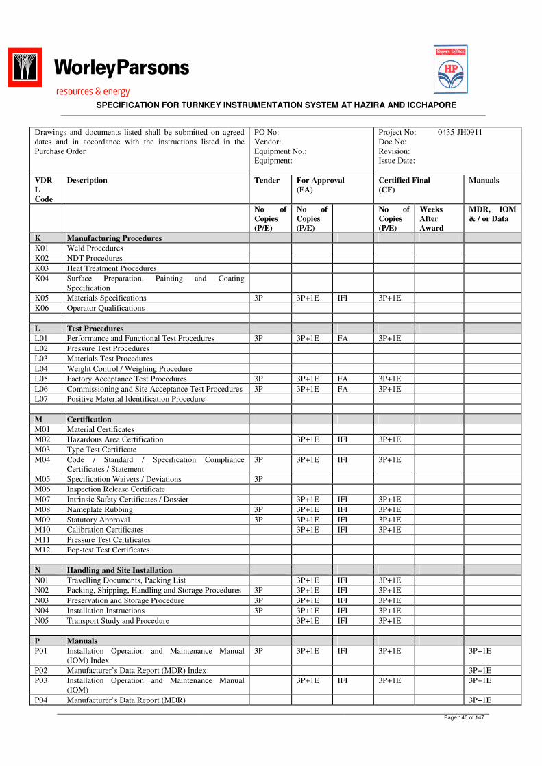
SPECIFICATION FOR TURNKEY INSTRUMENTATION SYSTEM AT HAZIRA AND ICCHAPORE
Page 140 of 147
Drawings and documents listed shall be submitted on agreed dates and in accordance with the instructions listed in the Purchase Order
PO No: Vendor: Equipment No.: Equipment:
Project No: 0435-JH0911 Doc No: Revision: Issue Date:
VDRL Code
Description Tender For Approval (FA)
Certified Final (CF)
Manuals
No of Copies (P/E)
No of Copies (P/E)
No of Copies (P/E)
Weeks After Award
MDR, IOM & / or Data
K Manufacturing Procedures K01 Weld Procedures K02 NDT Procedures K03 Heat Treatment Procedures K04 Surface Preparation, Painting and Coating
Specification
K05 Materials Specifications 3P 3P+1E IFI 3P+1E K06 Operator Qualifications L Test Procedures L01 Performance and Functional Test Procedures 3P 3P+1E FA 3P+1E L02 Pressure Test Procedures L03 Materials Test Procedures L04 Weight Control / Weighing Procedure L05 Factory Acceptance Test Procedures 3P 3P+1E FA 3P+1E L06 Commissioning and Site Acceptance Test Procedures 3P 3P+1E FA 3P+1E L07 Positive Material Identification Procedure M Certification M01 Material Certificates M02 Hazardous Area Certification 3P+1E IFI 3P+1E M03 Type Test Certificate M04 Code / Standard / Specification Compliance
Certificates / Statement 3P 3P+1E IFI 3P+1E
M05 Specification Waivers / Deviations 3P M06 Inspection Release Certificate M07 Intrinsic Safety Certificates / Dossier 3P+1E IFI 3P+1E M08 Nameplate Rubbing 3P 3P+1E IFI 3P+1E M09 Statutory Approval 3P 3P+1E IFI 3P+1E M10 Calibration Certificates 3P+1E IFI 3P+1E M11 Pressure Test Certificates M12 Pop-test Test Certificates N Handling and Site Installation N01 Travelling Documents, Packing List 3P+1E IFI 3P+1E N02 Packing, Shipping, Handling and Storage Procedures 3P 3P+1E IFI 3P+1E N03 Preservation and Storage Procedure 3P 3P+1E IFI 3P+1E N04 Installation Instructions 3P 3P+1E IFI 3P+1E N05 Transport Study and Procedure 3P+1E IFI 3P+1E P Manuals P01 Installation Operation and Maintenance Manual
(IOM) Index 3P 3P+1E IFI 3P+1E 3P+1E
P02 Manufacturer’s Data Report (MDR) Index 3P+1E P03 Installation Operation and Maintenance Manual
(IOM) 3P+1E IFI 3P+1E 3P+1E
P04 Manufacturer’s Data Report (MDR) 3P+1E

SPECIFICATION FOR TURNKEY INSTRUMENTATION SYSTEM AT HAZIRA AND ICCHAPORE
Page 141 of 147
Drawings and documents listed shall be submitted on agreed dates and in accordance with the instructions listed in the Purchase Order
PO No: Vendor: Equipment No.: Equipment:
Project No: 0435-JH0911 Doc No: Revision: Issue Date:
VDRL Code
Description Tender For Approval (FA)
Certified Final (CF)
Manuals
No of Copies (P/E)
No of Copies (P/E)
No of Copies (P/E)
Weeks After Award
MDR, IOM & / or Data
Q Test Results Q01 Performance Test Results 3P+1E Q02 Factory Acceptance Test Results 3P+1E Q03 Site Acceptance Test Results 3P+1E Q04 Noise Test Results 3P+1E Q05 Inspection and Test Results 3P+1E R Quality Assurance R01 QA Accreditation Certification (ISO 9001) 3P 3P+1E IFI 3P+1E R02 Quality Manual 3P 3P+1E IFI 3P+1E R03 Typical Quality Plan 3P+1E FA 3P+1E R04 Contract Specific Quality Plan 3P+1E FA 3P+1E R05 Typical Inspection and Test Plan 3P+1E FA 3P+1E R06 Contract Specific Inspection and Test Plan 3P+1E FA 3P+1E S Miscellaneous S01 Surface Preparation and Coating Test Reports S02 Vendor QA System Certification 3P+1E IFI Notes: Definitions / Requirement Status Format 1 Vendor to complete, indicating proposed schedule for
submission of documents in each relevant category and return with Tender.
2 CF documents due 2 weeks after receipt of FA documents. 3 Vendor shall provide a sample ITP with Tender. 4 MDR due 2 weeks after shipment 5 IOM documents due 4 weeks before shipment 6 NDT schedule shall show cross reference between weld
locations and NDT method, sensitivity and % examination. 7 Weld maps shall show cross reference between weld
locations, NDT method, WPS, Welder ID, NDT results, NDT reports and heat treatment charts.
8 Type test / approval certificates shall testify that equipment has been approved by an independent and internationally recognized test authority (Certifying Authority Design Approval Certificates).
IFI = For Information Only FA = For Approval CF = Certified Final IFC = Issued for Construction AB = As Built M = Include in MDR I = Include in IOM
P = Paper Print E = Electronic
9 Hard documentation shall be sent to: HPCL Mumbai-400093, Maharashtra, India
10 Electronic documentation shall be sent to the Document Controller at HPCL:
11 The Vendor shall include a document transmittal form with
each submission.

SPECIFICATION FOR TURNKEY INSTRUMENTATION SYSTEM AT HAZIRA AND ICCHAPORE
Page 142 of 147
Drawings and documents listed shall be submitted on agreed dates and in accordance with the instructions listed in the Purchase Order
PO No: Vendor: Equipment No.: Equipment:
Project No: 0435-JH0911 Doc No: Revision: Issue Date:
VDRL Code
Description Tender For Approval (FA)
Certified Final (CF)
Manuals
No of Copies (P/E)
No of Copies (P/E)
No of Copies (P/E)
Weeks After Award
MDR, IOM & / or Data
12 Vendor documentation shall include the following information: Project Name Project Number Purchase Order Number Equipment Name and Number Space for a WorleyParsons provided Document Number. This is in addition to the Vendor’s own Document Number.
13 The mentioned Mechanical / Civil / Electrical works / documentation / drawings are associated within the Terminal Automation System package. All other requirement outside of the packages shall be by Others:
Legend: MDR = Manufacturer’s Data Report IOM = Installation Operation and Maintenance Manual ITP = Inspection and Test Plan NDT = Non Destructive Testing WPS = Welding Procedure Specification

SPECIFICATION FOR TURNKEY INSTRUMENTATION SYSTEM AT HAZIRA AND ICCHAPORE
Page 143 of 147
ANNEXURE – 3 DATA SHEETS (PLS REFER ATTACHEMENTS)

SPECIFICATION FOR TURNKEY INSTRUMENTATION SYSTEM AT HAZIRA AND ICCHAPORE
Page 144 of 147
ANNEXURE – 4
ADDITION AND DELETION RATE
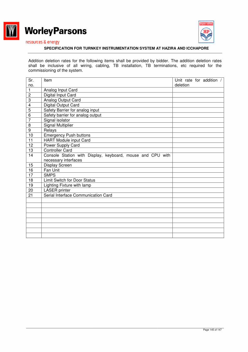
SPECIFICATION FOR TURNKEY INSTRUMENTATION SYSTEM AT HAZIRA AND ICCHAPORE
Page 145 of 147
Addition deletion rates for the following items shall be provided by bidder. The addition deletion rates shall be inclusive of all wiring, cabling, TB installation, TB terminations, etc required for the commissioning of the system. Sr. no.
Item Unit rate for addition / deletion
1 Analog Input Card 2 Digital Input Card 3 Analog Output Card 4 Digital Output Card 5 Safety Barrier for analog input 6 Safety barrier for analog output 7 Signal isolator 8 Signal Multiplier 9 Relays 10 Emergency Push buttons 11 HART Module input Card 12 Power Supply Card 13 Controller Card 14 Console Station with Display, keyboard, mouse and CPU with
necessary interfaces
15 Display Screen 16 Fan Unit 17 SMPS 18 Limit Switch for Door Status 19 Lighting Fixture with lamp 20 LASER printer 21 Serial Interface Communication Card

SPECIFICATION FOR TURNKEY INSTRUMENTATION SYSTEM AT HAZIRA AND ICCHAPORE
Page 146 of 147
ANNEXURE – 5 INSTRUMENTATION INDEX (PLS REFER ATTCAHMENTS) ANNEXURE – 6 PLC SYSTEM CONFIGURATION (PLS REFER ATTACHMENTS) ANNEXURE – 7
DRAWINGS – CONTROL ROOM LAYOUT FOR HAZIRA & ICCHAPORE (PLS REFER ATTACHMENTS)
ANNEXURE - 8 DRAWINGS – P & ID’S (PLS REFER ATTACHMENTS) ANNEXURE-9 GENERAL SPECIFICATION FOR INSTRUMENTATION (PLS REFER ATTACHMENTS) ANNEXURE-10 SPECIFICATION FOR INSTRUMENT CABLES (PLS REFER ATTACHMENTS) ANNEXURE-11 SPECIFICATION FOR JUNCTION BOXES, CABLE TRAYS AND GLANDS (PLS REFER ATTACHMENTS)

SPECIFICATION FOR TURNKEY INSTRUMENTATION SYSTEM AT HAZIRA AND ICCHAPORE
Page 147 of 147
ANNEXURE-12 DRAWING- PLOT PLAN (HAZIRA ) (PLS REFER ATTACHMENTS)