teoria ph metria
TRANSCRIPT

pH MEASUREMENT GUIDE
R
T H E M E A S U R E O F E X C E L L E N C E TM
By Erich K. Springer

Page 1
Table of Contents
1 INTRODUCTION....................................................................................................................... 3
1.1 Booklet Overview ............................................................................................................. 4
2 THE PH SCALE........................................................................................................................ 5
3 THE PH MEASUREMENT........................................................................................................ 7
3.1 The NERNST Equation .................................................................................................... 7
3.2 The pH Measuring System............................................................................................. 11
3.2.1 The Measuring Electrode.................................................................................................. 11 3.2.2 The Reference Electrode.................................................................................................. 13 3.2.3 The Combination (Single Rod) Electrode......................................................................... 14 3.2.4 Combination Electrode filled with KCl-Gel as a Reference Electrolyte ............................ 15 3.2.5 Reference Electrode with POLISOLVE Electrolyte (Polymer).......................................... 15 3.2.6 The Measurement of the Potential Difference.................................................................. 16
3.3 The Characteristics of a pH Measuring Chain................................................................ 17
3.3.1 The Different Potentials of a Combination Electrode ....................................................... 17 3.3.2 The Zero point of an Electrode Assembly ........................................................................ 18 3.3.3 The Asymmetry Potential.................................................................................................. 19 3.3.4 The Slope or Sensitivity of a pH Electrode Assembly ...................................................... 20 3.3.5 The Isotherm Intersection Point........................................................................................ 22
3.4 The Diaphragm............................................................................................................... 23
3.4.1 The Diffusion Potential...................................................................................................... 25 3.4.2 Diaphragm Contamination through Chemical Reaction ................................................... 26
3.5 Alkaline and Acid Error................................................................................................... 27
3.5.1 Alkaline Error .................................................................................................................... 27 3.5.2 Acid Error.......................................................................................................................... 28
3.6 Temperature Influence and Temperature Compensation .............................................. 28
3.7 Various Electrode Shapes.............................................................................................. 30
3.8 Ageing ............................................................................................................................ 32
3.8.1 The Ageing of a Measuring Electrode .............................................................................. 32 3.8.2 The Ageing of the Reference Electrode ........................................................................... 33
3.9 Calibration ...................................................................................................................... 34
3.9.1 pH Standard and Technical Buffer Solutions ................................................................... 34 3.9.2 The Calibration Procedure................................................................................................ 37 3.9.3 Re-calibration.................................................................................................................... 40 3.9.4 Response Time................................................................................................................. 41 3.9.5 Reasons for calibration problems ..................................................................................... 41
3.10 The Accuracy to be Expected ................................................................................. 42

Page 2
4 ELECTRODE HANDLING...................................................................................................... 43
4.1 Storage............................................................................................................................43
4.1.1 The Storage of Measuring Electrodes .............................................................................. 43 4.1.2 The Storage of Reference Electrodes .............................................................................. 44 4.1.3 The Storage of Combination Electrodes........................................................................... 44
4.2 Cleaning of Electrode Assemblies ..................................................................................45
4.3 Refilling or Replacing the Reference Electrolyte.............................................................46
5 THE CONNECTION OF THE PH ELECTRODES TO THE PH MEASURING INSTRUMENT ........................................................................................... 46
5.1 Measuring Electrode Connection Cable..........................................................................46
5.2 Reference Electrode Connection Cable..........................................................................47
5.3 Combination Electrode Connection Cable ......................................................................47
5.4 Cable Preparation and Cable Routing ............................................................................47
5.5 Plug or Cable? ................................................................................................................48
6 APPENDIX: THE HYDROGEN ION CONCENTRATION....................................................... 49
6.1 The Atom Structure .........................................................................................................49
6.2 The Bohr Atom................................................................................................................49
6.3 The Periodic Table of Elements ......................................................................................51
6.4 The Molecule...................................................................................................................51
6.5 The Ion............................................................................................................................53
6.6 Dissociation.....................................................................................................................53
6.7 Acids – Bases – Salts .....................................................................................................54
6.8 The Mole .........................................................................................................................56
6.9 The Hydrogen Ion Concentration in Aqueous Solutions .................................................56

Page 3
pH Measurement utilising
Glass Electrodes Theory and Practice
by Erich K. Springer
1 INTRODUCTION
Since the creation of man, he could differentiate between sour and bitter when eating liquid or solid foods. We say that vinegar and lemon juice taste sour and that soap water tastes bitter. This characteristic of these liquids and the marked degree of sour or bitter is indicated by the pH value. The significance of the pH value is today known to a great portion of our population alone through the fact that it is accepted that the pH value of swimming-pool water has to be kept within certain limits. The food we eat contains a lot of water and our drinks are nothing else than coloured and flavoured water, and this water can be either sour or bitter; or in other words, it will have a certain pH value.
In general we can say that water is the most important substance on earth. Without water there will be no life on our planet. People living in areas of severe drought have experienced the importance of water for their existence. Continuous droughts do not only affect the farmers, they are a disaster for the entire economy of a nation. It is therefore of utmost importance that we treat this precious liquid with care, use it responsibly and try to save every drop of it.
Water is everywhere! Three quarters of the surface of the earth is covered with water in the form of oceans, rivers, lakes and swamps. Brandy, whiskey, beer, wine, cool-drinks, fruit juices, coffee and tea consist of water containing certain additives which change the property and the taste of the water. Blood, the vital liquid of our body is mainly water, in fact our entire body consists of approximately 65% water.
Water is used in industry as cooling water, wash water, boiler water, steam, condensate and solvent. Dirty water is usually disposed of as effluent. Notably the chemical industry especially makes use of this universal solvent, because most substances are somewhat soluble in water.
Page 4
Through its usage water undergoes changes, the most substantial being the change of its hydrogen ion concentration. All the above mentioned liquids differ in their hydrogen ion concentrations, which makes them either acids or bases, sour or bitter. A measure for the hydrogen ion concentration of aqueous solutions is the pH value.
It can be said that the human tongue is the first pH measuring instrument, but only the potentiometric pH measurement provides an accurate and reproducible result, when the acidity or alkalinity of an aqueous solution has to be determined.
The pH measurement is therefore of vital significance in such diverse fields as biology, medicine, food technology, drinking water treatment, agriculture, mineralogy, surface treatment in metal processing, paper and textile manufacturing, chemical and petrochemical industry as well as waste water and sewage treatment for environmental protection.
On a daily basis the importance of measuring the pH value in industry becomes more significant and with it new problems in process control appear and have to be solved. Even in laboratories is the demand for a highly accurate and repeatable pH measurement a predominating factor.
The purpose of this booklet is to supply the basic knowledge of the pH measurement in a brief and understandable form. If it helps to eliminate the myths and mistakes arising from conceptual misunderstanding and if it leads to a successful application of pH measurement the author has fulfilled his task.
1.1 Booklet Overview
Without a basic knowledge of a few chemical principles as well as of potentiometry and the functionality of a pH electrode a successful pH measurement is practically impossible.
Therefore certain chemical and physical principles are described in the appendix of the booklet. These explanations will lead to the definition of the hydrogen ion concentration.
The book starts with the definition of the pH scale, explaining the NERNST equation and describing the fundamentals of the glass and reference electrode. pH related terminology will be dealt with in detail, the knowledge of this will lead to the successful application of the various HAMILTON pH electrodes.
One cannot achieve a better measuring accuracy than the accuracy of the buffer solution one uses for calibration. HAMILTONS buffer solutions are described, after which the calibration of the pH measuring system is explained.
Connecting the pH electrode to the measuring instrument and the “do’s and don’ts” of electrode handling will conclude the subject of pH measurement.
Acknowledgements
Many thanks go to Dr. Hannes Bühler of HAMILTON who helped me in this venture. He read my first lecture book, advised me on certain subjects and corrected the odd mistakes.
I also want to thank Andreas Brügger and Dirk Tillich, both of HAMILTON, for providing me with special information and material.
Finally I want to thank my loving wife for her patience and understanding.

Page 5
2 THE pH SCALE
If we express the hydrogen ion concentration of an aqueous solution in relation to its molecular value we derive a scale of 1 (100) via 10-7 to 10-14 mole/litre.
This scale is impractical but if written as a function of its negative logarithm a real and simple scale of 0 – 14 has been created: the pH scale.
H+ concentration
(mole/litre)
OH- concentration
(mole/litre)
pH
1
0.1
0.01
0.001
0.0001
0.00001
0.000001
0.00000000000001
0.0000000000001
0.000000000001
0.00000000001
0.0000000001
0.000000001
0.00000001
0
1
2
3
4
5
6
0.0000001 0.0000001 7
0.00000001
0.000000001
0.0000000001
0.00000000001
0.000000000001
0.0000000000001
0.00000000000001
0.000001
0.00001
0.0001
0.001
0.01
0.1
1
8
9
10
11
12
13
14
pH is the abbreviation of pondus hydrogenii and means the weight of hydrogen. This term was introduced in 1909 by the Danish biochemist S. P. L. Sørensen (1868 – 1939).
The pH scale covers the active concentration of the H+ ions and OH¯ ions and therefore the pH value is defined as the negative common logarithm of the active hydrogen ion concentration in an aqueous solution.
If the H+ ion concentration changes by a factor of ten, the pH value changes by one unit. This illustrates how important it is to be able to measure the pH value to a tenth of a unit or even a hundredth of a unit in special applications.
The pH definition refers to the active hydrogen ion concentration and not just to the hydrogen ion concentration. It is important to understand this difference. Only in dilute solutions are all anions and all cations so far apart that they are able to produce the maximum of the chemical energy, i.e. the H+ ion concentration and the H+ ion activity are identical. For instance 0,01 mole hydrochloric acid is still classified as a dilute solution which dissociates completely and therefore concentration equals activity.
0,01 mole HCl: concentration = activity
pH = log hydrogen ion concentration ( mole/litre) 1

Page 6
If the HCl concentration increases, the cation (H+) and the anion (Cl¯) obstruct each other increasingly as the space between them gets smaller and smaller. In this case the ion activity is slowed down and does not correspond any longer with the ion concentration. With increasing concentration the ion activity differs to the ion concentration more and more.
It is important to recognise the fact that a pH measurement determines only the concentration of active hydrogen ions in a solution, and not the total concentration of hydrogen ions. It is this factor that is responsible for the observed pH change in pure water with temperature.
If the temperature rises in pure water, the dissociation of hydrogen and hydroxyl ions increases. Since pH is related to the concentration of dissociated hydrogen ions alone, the pH value actually decreases although the water is still neutral. Therefore it is very important that we know the relationship between the dissociation constant and temperature, otherwise it is not possible to predict the pH value of a solution at a desired temperature from a known pH reading at some other temperature.
The meaning of the pH scale is best explained if we compare the concentration of 1 mol/l pure hydrochloric acid (HCl) which has a pH value of 0, with a concentration of 1 mol/l pure sodium hydroxide (NaOH) which has a pH value of 14. When both solutions are mixed in same quantities, a neutralisation reaction occurs as may be seen by the following equation:
The acidic and alkaline properties of the solutions are lost because of the union of the hydrogen and hydroxyl ions which form water. The newly formed sodium chloride (table salt) does not influence the pH value.
Generally the following can be stated:
if the concentration of active hydrogen and active hydroxyl ions in a solution is of the same quantity, the solution is neutral (pH value = 7)
if the solution has a higher concentration of active hydrogen ions than that of hydroxyl ions, the solution is an acid ( pH value below 7)
if the solution has a higher concentration of active hydroxyl ions than that of hydrogen ions, the solution is a base (pH value above 7)
1 mole HCl: concentration > activity
HCl + NaOH HOH + NaCl H2O + NaCl pH 0 + pH 14 pH 7

Page 7
3 THE pH MEASUREMENT
3.1 The NERNST Equation
To determine the active hydrogen ion concentration, a pH measurement is necessary.
Three methods are generally used for the direct determination of the pH value in aqueous solutions:
1) The visual method, a colour comparison with pH sensitive indicator paper (litmus) to a standard colour scale.
Milkof
Magnesia
The pH Scale
pH 0 1 2 3 4 5 6 7 8 9 10 11 12 13 14
1 mole/l HCl 1 mole/l NaOH
HOH10 mole HCl-1 -110 mole NaOH
neutralincreasing acidity increasing alkalinity
pH 0 1 2 3 4 5 6 7 8 9 10 11 12 13 14
GastricJuices
LemonJuice
SourMilk
Yoghurt
Beer
CoffeeMilk
Blood
WellWater
SoapSuds
HouseholdAmmonia

Page 8
2) The photometric method, using a spectrophotometer to measure the wave- length of the pH sensitive coloured solution.
3) The potentiometric method, an electro-chemical measurement, measuring the e.m.f created by a chemical reaction, such as that which takes place between metals and dissolved salts.
The potentiometric method in determining the pH value of aqueous solutions is the only method which can be used in process control as a continuous in-line measurement and therefore this booklet will deal exclusively with this method of pH determination.
This pH measurement method is based on the NERNST equation which describes in a relatively simple form the relationship between the galvanic potential of a defined electrode assembly and the chemical activity of the ion concentration being measured.
An electrode assembly always consists of a measuring electrode which is sensitive to the ion activity to be measured and a reference electrode. The operation of an electrode assembly in its simplest form is demonstrated by the following example:
If two hydrogen electrodes (each a thin plate of polished platinum) are immersed in two solutions, having different hydrogen ion concentrations, each electrode will generate a potential which depends on the active hydrogen concentration of the solution in which the electrode is immersed. To be able to measure this potential, the two solutions are connected by a salt bridge (electrolyte bridge) and the two electrodes are connected to a high impedance voltmeter. Both solutions are saturated with pure hydrogen gas.
Since the current passing during such a measurement is negligible, the chemical composition of the sample solution is not altered. The bridge acts as a phase boundary between solution C1 and solution C2 and closes the electric circuit.
A potential difference will be generated between the two platinum electrodes by the different active hydrogen-ion concentrations in the solutions. The relationship is expressed by the NERNST equation:
where:
E = potential difference (mV)
R = gas constant (8,31439 J x mol-1 x K-1)
F = Faraday constant (96495,7 C x mol-1)
C1 C2
Pt Pt
Electrolyte Bridge
High impedance mV meter
mV
0
+1500-1500
2
1
C
C log x
x F n
T x R
E

Page 9
T = absolute temperature in Kelvin (K)
n = charge number of the measured ion (in this case nH = 1)
C1 = active H-ion concentration in solution C1
C2 = active H-ion concentration in solution C2
If we select between C1 and C2 a concentration ratio of 10:1, the equation may be written as:
E is known as the NERNST’s potential, given the symbol UN. UN corresponds to the change in potential with a ten-fold change in activity.
2,303585Fn
TRE
1
10log
Fn
TRE
C
Clog
Fn
TRE
2
1

Page 10
The values of R and F are constant. The charge number n is known for each kind of ion and the temperature T can be calculated from the measured value in °C.
If we assume the temperature of the solutions to be 20 °C, then:
T = 273,15 + 20 = 293,15 Kelvin
This will give us a NERNST potential of
As the ion activity is temperature dependent, so is the NERNST potential (refer to the NERNST equation). The following table illustrates the temperature dependency:
UN = 58,16 mV
0mV
mV at 20 C
pH 0 1 2 3 4 5 6 7 8 9 10 11 12 13 14
1 mole/l HCl 1 mole/l NaOH
HOH10 mole HCl-1 -110 mole NaOH
pHpHpH
-58,16mV
+58,16mV
2x+58,16mV=116,32 mV
407,12mV
+ 407,12mV
The pH Scale and the Related NERNST Potential
o
T UN T UN T UNoC mV
oC mVoC mV
0 54.20 35 61.14 70 68.085 55.19 40 62.13 75 69.08
10 56.18 45 63.12 80 70.0715 57.17 50 64.12 85 71.0620 58.16 55 65.11 90 72.0525 59.16 60 66.10 95 73.0430 60.15 65 67.09 100 74.04
Temperature Dependency of the NERNST Potential

Page 11
3.2 The pH Measuring System
A basic pH measuring system consists of
(1) the measuring electrode, a pH sensitive electrode,
(2) the reference electrode
and (3) a high impedance voltmeter.
3.2.1 The Measuring Electrode
The purpose of the measuring electrode is to determine the pH value of an aqueous solution.
The platinum/hydrogen electrode was originally used to measure the hydrogen ion concentration in aqueous solutions (since 1897) and today still serves as a reference standard for the electrometric pH determination. The hydrogen electrode consists of a platinised platinum plate or rod (coated with platinum black), subjected to a flow of gaseous hydrogen. A silver wire coated with silver chloride serves as a reference electrode.
The basic theory, when employing a hydrogen electrode, is as follows: If a metal rod (electrode) is immersed into an aqueous solution containing its own salt (silver electrode in silver nitrate), the atoms on the surface of that metal rod will ionise. The water molecules will attract the positively charged metal ions from the surface of the rod, which leaves the metal rod negatively charged. This charge exchange develops a potential difference at the phase boundary metal/solution. The potential depends on the ion concentration in the solution and is known as the galvanic potential.
Today the hydrogen electrode still serves as a reference standard especially as its measuring results are extremely accurate. However for practical reasons the hydrogen electrode has lost its importance because of its difficult and complicated handling.
Only the antimony electrode has survived out of various metal electrodes. Antimony is chemically resistant to hydrofluoric acid and can therefore be used for the pH measurement in solutions containing hydrofluoric acid. However, the accuracy and reproducibility of the measuring result incorporates large tolerances.
High impedance voltmeter
Referenceelectrode
Measuringelectrode
Electrodeassembly
mV
0
+1500-1500
(1)
(2)
(3)

Page 12
3.2.1.1 The Glass Electrode
It was not until the development of the glass electrode that pH measurement became a simple and reliable tool for all kinds of applications. In recent years the glass electrode has outgrown all other types of indicator electrodes for pH measurements. The pH determination of an aqueous solution is today as common as temperature and pressure measurements, thanks to the reliability and accuracy of the glass electrode in combination with extreme stable electronic amplification. However, the successful application of the glass electrode requires some knowledge about its functionality and its maintenance, which this booklet will provide.
A glass electrode consists of a shaft made from glass which should be highly resistant to hot alkaline solutions and its electrical resistance must be several times greater than that of the membrane glass. The pH sensitive part of the glass electrode is the normally cylindrically shaped electrode tip, the glass membrane. The membrane is made from special hydrogen ion sensitive glass and is fused to the electrode shaft. The glass electrode is partly filled with a buffer solution, normally having a pH value of 7.
A defined amount of potassium chloride (KCl) is added to this internal buffer.
A silver wire, coated with silver chloride (Ag/ AgCl) is inserted into the glass electrode right down into the internal buffer and serves as a conducting electrode. Via the core of the coaxial pH cable, the Ag/AgCl wire is connected to one terminal of a pH meter.
3.2.1.2 The Glass Membrane
All types of glasses possess the property of producing a potential difference relative to the hydrogen ion concentration in aqueous solutions. However only special types, such as the conventional Mc-Innes glass (Corning 015) produce galvanic potentials which satisfy the NERNST equation over a wide range of the pH scale.
Every manufacturer of pH electrodes is constantly researching for better pH sensitive glasses. Through constant development HAMILTON has achieved results which have not previously been available without unsatisfactory compromises.
When the membrane glass of a measuring electrode comes into contact with an aqueous solution, it forms a thin gel layer of approximately 10-4 mm thickness between the glass surface and the solution. The thickness of the gel layer depends on the quality and composition of the membrane glass, the temperature and the pH value of the measured solution. As the internal side of the glass membrane is in contact with the inner buffer (an aqueous solution of pH 7) a gel layer is also formed on the inside of the glass membrane.
The Construction of a Glass Electrode
Electrode head
Screen
Internal conductorelectrode (Ag/AgCl)
pH sensitiveglass membrane
Inner buffer + KCl (pH 7)
Electrode glass shaft
pH cable

Page 13
A continuous exchange of H+ ions in the gel layers and H+ ions of the solutions takes place on both sides of the membrane. This ion exchange is controlled by the H+ ion concentration of both solutions.
If the hydrogen ion concentration of each solution is identical on both sides of the glass membrane, the ion exchange stops after an equilibrium has been reached between the H+ ions in the solutions and the H+ ions in the gel layers. Therefore, both sides of the membrane glass have the same potential and the potential difference is 0 mV.
If a difference of a hydrogen ion con-centration exists between the inner buffer and the outer solution, a potential difference develops between the inner and outer sides of the membrane glass which is proportional to the difference in pH between the inner buffer and the outer solution. To be able to measure the membrane potential, the membrane itself has to be conductive. This is achieved by the mobility of the alkaline ions in the membrane glass (Li+ ions in most glasses today or Na+ ions in older membrane glasses).
The thickness and composition of the gel layer determine the response time and the characteristic slope of the glass electrode. Therefore the gel layer is of critical importance to the electrode performance.
Without the gel layer there can be no pH measurement. Unfortunately it takes approximately one to two days until a gel layer is fully developed. Therefore a measuring electrode needs to be hydrated (immersed into normal clean tap water) for at least 24 hours prior to use. Most manufacturers deliver their electrodes already hydrated (the membrane is kept wet with a KCl solution in a plastic cap) which renders the electrode ready for immediate use.
3.2.2 The Reference Electrode
The reference electrode represents a defined electrical connection between the measured medium and the pH meter. The accuracy of the pH measurement is often determined by the reference electrode and therefore the choice of the reference electrode is of significant importance. An ideal reference electrode should produce a predictable potential, which should respond only in accordance with the NERNST equation. A good and stable reference electrode should also have a low temperature coefficient and possess no temperature hysteresis.
A reference electrode consists of an internal electrode (similar to the measuring electrode) which is immersed into a defined electrolyte. This electrolyte must be in contact with the measured medium. Over the years various reference systems have been employed, but only two systems, the mercury-mercurous chloride (calomel) and the silver-silver chloride reference electrodes were found reliable with respect to an accurate and stable potential.
HAMILTON applies exclusively the silver-silver chloride reference system. (refer also to “The EVEREF reference system” on page 25).
The Glass Membrane
pH 7
Ag/AgCl electrode
H = const.+
H+H+
Outer gel layerapprox. 10 mm thick
< pH 7 > pH 7
Measured medium
Glass membraneappr. 0,5 to 1mm thick
Inner gel layerapprox. 10 mm thick
+
+++
+
+
+Li
Li
Li
Li
Li
+
+
+
+
+

Page 14
At low and stable temperatures (max. 80 °C) the calomel electrode has a high potential stability and a high accuracy down to a hundredth of a millivolt.
But today the silver/silver chloride electrode has gained practical acceptance and is by far the most frequently employed reference system. It is easy to manufacture, its potential rapidly attains equilibrium between –30 °C and 135 °C, and is very reproducible. The Ag-AgCl reference electrode remains stable and accurate especially with wide temperature fluctuations and at high temperatures up to 135 °C.
The internal electrode of an Ag-AgCl reference electrode consists of a silver chloride coated silver wire which is immersed into potassium chloride of 3 mole concentration situated in a large chamber formed by the glass body of the reference electrode.
A diaphragm (normally a small porous ceramic rod) is fitted at the bottom of this chamber to permit the potassium chloride to diffuse or leak into the measured medium. To complete the electric circuit the silver-silver chloride wire is connected via a coaxial cable to the pH meter.
3.2.3 The Combination (Single Rod) Electrode
Since 1947 electrode manufacturers have combined the measuring electrode and the reference electrode into one unit, hence the name combination electrode. Today, the combination electrode is almost exclusively employed in laboratories and industrial plants. Only when the life expectancy is significantly different for the measuring and the reference electrode, is the use of a pH measuring system consisting of two separate electrodes recommended.
In a combination electrode the concentric space surrounding the measuring electrode is filled with the reference electrolyte and contains the internal reference system. A diaphragm near the bottom of the electrolyte chamber serves as the junction between the KCl solution and the measured medium. As the reference electrolyte is a conductive medium, it acts as a screen to the measuring electrode.
The Constructionof a
Reference Electrode
pH cable
Electrode head
Electrodeglass shaft
Refill opening
Internal reference system
3 mole KCl
Diaphragm
Internal conductorelectrode (Ag/AgCl)
Diaphragm
The Constructionof a
Combination Electrode
Electrode head
pH sensitiveglass membrane
Inner Buffer + KCl (pH 7)
Electrode glass shaft
pH cable
Refill opening
Reference system
3 mole KCl
Page 15
3.2.4 Combination Electrode filled with KCl-Gel as a Reference Electrolyte
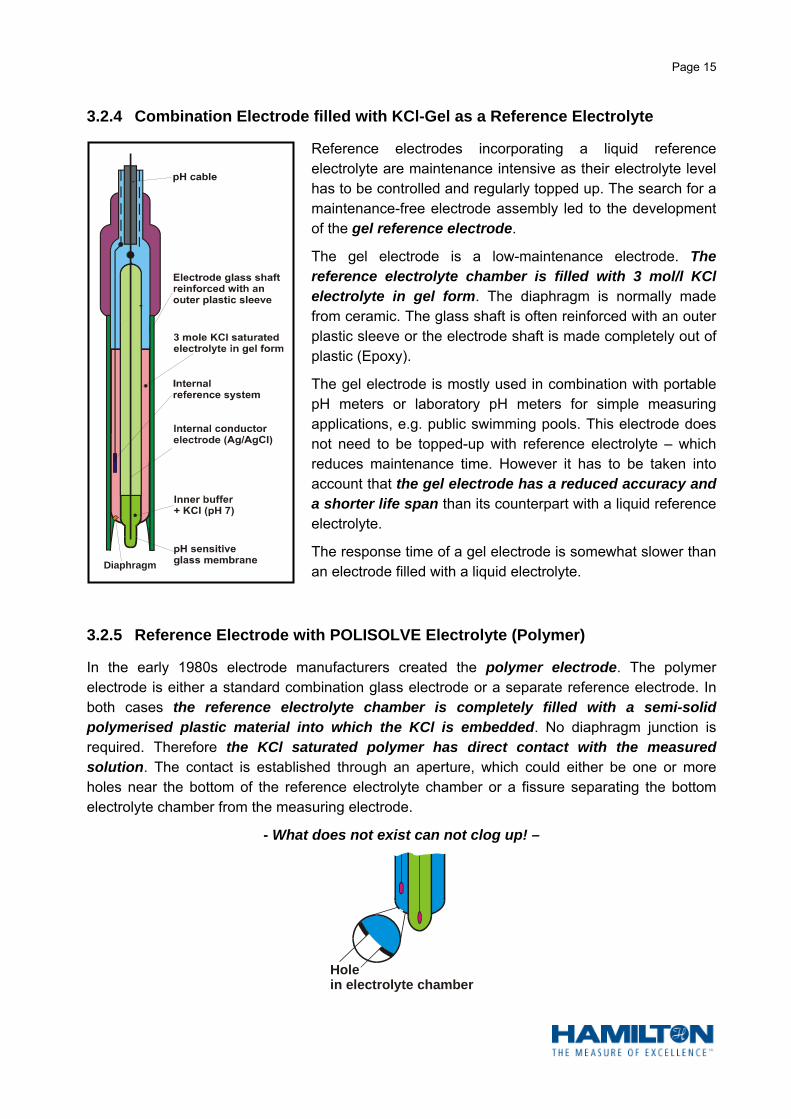
Reference electrodes incorporating a liquid reference electrolyte are maintenance intensive as their electrolyte level has to be controlled and regularly topped up. The search for a maintenance-free electrode assembly led to the development of the gel reference electrode.
The gel electrode is a low-maintenance electrode. The reference electrolyte chamber is filled with 3 mol/l KCl electrolyte in gel form. The diaphragm is normally made from ceramic. The glass shaft is often reinforced with an outer plastic sleeve or the electrode shaft is made completely out of plastic (Epoxy).
The gel electrode is mostly used in combination with portable pH meters or laboratory pH meters for simple measuring applications, e.g. public swimming pools. This electrode does not need to be topped-up with reference electrolyte – which reduces maintenance time. However it has to be taken into account that the gel electrode has a reduced accuracy and a shorter life span than its counterpart with a liquid reference electrolyte.
The response time of a gel electrode is somewhat slower than an electrode filled with a liquid electrolyte.
3.2.5 Reference Electrode with POLISOLVE Electrolyte (Polymer)
In the early 1980s electrode manufacturers created the polymer electrode. The polymer electrode is either a standard combination glass electrode or a separate reference electrode. In both cases the reference electrolyte chamber is completely filled with a semi-solid polymerised plastic material into which the KCl is embedded. No diaphragm junction is required. Therefore the KCl saturated polymer has direct contact with the measured solution. The contact is established through an aperture, which could either be one or more holes near the bottom of the reference electrolyte chamber or a fissure separating the bottom electrolyte chamber from the measuring electrode.
- What does not exist can not clog up! –
Diaphragm
Holein electrolyte chamber

Page 16
Since its inception polymer electrodes had a limited use. pH values below 2 pH could not be measured, the temperature limit was 90 °C, and measurements in media containing organic solvents were not possible.
With HAMILTON’s new developed POLISOLVE polymer (protected by patent law) these limitations are a thing of the past. The POLISOLVE polymer reference system allows pH measurements down to pH 0, and it is resistant to organic solvents. pH measurements in the laboratory or at industrial plants utilizing the POLISOLVE reference system are reliable and accurate. The POLISOLVE polymer can be applied to almost every measuring problem, including very dirty, fatty, oily, ion weak or protein media. Suspended solids do not create diaphragm problems any more.
As the KCl saturated polymer is free of AgCl, there is no possibility of silver sulphide contamination when measuring the pH value of solutions containing sulphides.
The high pressure rating of 600 kPa, its extended temperature rating of up to 130°C and its main-tenance-free operation should make the POLISOLVE reference system always a first choice.
Electrodes, utilizing the POLISOLVE polymer electrolyte, are even suitable for steam sterilisation in biotechnology applications.
3.2.6 The Measurement of the Potential Difference
The pH measuring electrode and the pH reference electrode form a so-called pH measuring chain within the measured medium. This chain can be compared to a battery of which the voltage produced depends on the measured medium.
The difference in potential between the measuring electrode and the reference electrode is a function of the pH value of the measured medium. In theory the voltage changes by 58,16 mV per pH unit at 20 °C according to the NERNST equation. The voltage produced by the pH measuring chain is large enough not to present any problem for a measurement. But the measuring chain is a voltage source from which no current can be drawn, not even the low current which a moving coil of a DC voltmeter draws. The potential difference of the measuring chain has to be measured without drawing any current from the voltage source, otherwise the voltage would be reduced and the pH measurement would be drastically falsified. The reason is the high electrical resistance of the glass electrode which is mainly determined by the resistance of the glass membrane.
The resistance values of a glass membrane vary between 10 M and 1 000 M at 25 °C and increase 10 times at a temperature decrease of 25 °C. The lowest possible operating temperature of a pH electrode is often determined by the resistance increase of the glass membrane at low temperatures, the internal resistance of the measuring instrument, the required accuracy of the pH measurement and the freezing point of the electrolyte.
High impedance voltmeter
ReferenceelectrodeMeasuring
electrode
Electrodeassembly
ThepH
measuringchain
Measured medium
mV
0
+1500-1500

Page 17
Special electrodes are manufactured for pH measurements at very low temperatures, having especially low resistance due to a particular glass composition and reduced membrane thickness. In order to still achieve an accuracy of +/- 0,1 pH the resistance of the measuring electrode should not be higher than a hundredth of the internal resistance of the measuring instrument. The upper limit of the membrane resistance lies at 5 000 M (5 x 10⁹). Membrane resistance that is too high causes faults and disturbances in the electronic measuring instrument.
The e.m.f. produced by the high resistance measuring chain can only be measured by an instrument having such a high internal resistance that it does not draw a current from the chain. For practical purposes the pH meter or pH transmitter should therefore have an internal resistance of at least 1012 ohms.
3.3 The Characteristics of a pH Measuring Chain
The characteristics of a pH measuring chain are the result of the individual properties of the measuring and the reference electrode. Most of the electrode assemblies in use today are combination electrodes. For this reason we will refer to the combination electrode when examining the different properties of a measuring chain. However everything that is said about the properties of a combination electrode may be applied to the individual measuring and reference electrode as well.
3.3.1 The Different Potentials of a Combination Electrode
Potential developing on the outer gel layer.
Asymmetry potential of the glass membrane.
Potential developing on the inner gel layer.
Potential developing on the internal conductor electrode.
Potential developing on the reference electrode.
Diffusion potential of the diaphragm.
The total potent ial measured by a pH electrode assembly is the sum of potentials E to E .E
E
E
1
2
E3
E4
5
E6
totalE
E2:
E1:
E6:
totalE :
E5:
E3:
E4:
1 6
mV
0
+1500-1500

Page 18
When a combination electrode is immersed into a solution to be measured, a potential develops at the outer gel layer of the glass membrane which forms a phase boundary between the glass membrane and the measured solution. This potential is dependent on the pH value of the measured solution and is therefore of primary interest. Unfortunately this potential cannot be measured individually as there are more phase boundaries in a pH measuring chain which all produce their individual potentials. Only the resultant e.m.f. of all single potentials added together is measurable and forms the mV value of the pH determination.
As can be seen from the picture above there are six potentials which develop on a pH measuring chain, but only one potential – E1 – is dependent on the pH value of the solution under test. Ideally the potentials E2 to E6 should stay constant during the measuring time in order to enable the measurement of the variable potential of E1.
E2 is the asymmetry potential of the glass membrane. If the measuring and the reference electrode possess the same internal conducting system and if the measuring chain is immersed into a buffer solution having the same pH value as the internal buffer solution, the potential difference between the inside and the outside of the glass membrane should theoretically be 0 mV. However, in reality even a new and perfect electrode assembly will show an asymmetry potential of a few millivolts. The asymmetry potential depends mainly on the different thickness of the gel layers and on the thickness of the glass membrane.
E3 is the potential which develops on the inner gel layer of the glass membrane and is dependent on the hydrogen ion concentration of the inner buffer solution. As this buffer solution does not change in value, the potential E3 should be constant at all times.
E4 and E5 are potentials which develop on the phase boundaries metal/buffer solution (measuring electrode) and metal/electrolyte (reference electrode). If both conductor systems are identical and buffer solution and electrolyte have the same chloride ion activity the E4 and E5 neutralise each other and do not contribute to the total potential measured by the pH measuring device.
E6 is the diffusion potential of the diaphragm. This potential occurs at the boundary between two electrolytes, when both differ in concentration and composition. It is determined by the diffusion of ions having different polarity and different ionic mobility.
As stated earlier, potentials E2 to E6 should ideally be constant in order to determine E1. Since the individual potentials E2 to E6 are subject to certain errors, there is a resultant zero point error of the electrode assembly. This is why a zero point calibration is required before a pH mea-surement can commence and be repeated in regular time intervals during the measurement duration.
3.3.2 The Zero point of an Electrode Assembly
The zero point of an electrode assembly is the pH value at which the electrode assembly potential Etotal is equal to 0 mV. Theoretically the zero point of a pH measuring chain is determined by the internal buffer solution of the measuring electrode, which under normal circumstances has the value of pH 7. If the pH value of the measured medium also equals pH 7, then the potential difference of the pH measuring chain should be 0 mV.
In practice however this is seldom the case, because Etotal is the resultant of the chain potentials E1 to E6. Each potential reacts differently to temperature changes and to the composition of a

Page 19
measuring solution. Therefore it is difficult, if not impossible, to produce a pH electrode assembly with an accurately defined and reproducible zero point.
The zero point tolerance, as stipulated by the German Industrial Standard (DIN), may vary within –30 mV and +30 mV. Many manufacturers of pH electrodes deliberately set their electrode assembly zero point (pH 7 = 0 mV) slightly lower (approximately pH 6,8) since the zero point tends to drift upwards during the ageing process of the electrode assembly.
The repeatability of a pH electrode assembly (the uncertainty factor) is seldom stated by electrode manufacturers. Experience has shown that the repeatability of a pH electrode assembly seldom exceeds +/- 0,02 pH (≈1,16 mV).
The exact zero point deviation of a pH electrode assembly has to be established by the user, prior to a pH measurement, and must then be compensated for by the zero adjustment potentiometer at the pH meter/transmitter. Microprocessor based pH meters adjust the zero point of an electrode assembly automatically during the calibration procedure.
The zero point check and adjustment has to be repeated at specific time intervals during the measurement process, as the zero point tends to drift due to the following reasons:
a) Penetration of the measured solution into the reference electrolyte via the diaphragm. This will either poison or dilute the reference electrolyte. Both will change the chloride ion activity of the electrolyte, resulting in a change of the reference potential.
b) A change of the internal buffer solution. Due to the exposure to high temperature the glass membrane of the measuring electrode releases alkali hydroxide into the inner buffer solution which gradually increases its pH value.
c) Increase in electrode plug and cable contact resistance due to corrosion of the contact metals.
3.3.3 The Asymmetry Potential
In theory the potential difference across the glass membrane of a measuring electrode should be 0 mV if both the inner buffer solution and the measured solution possess an equal pH value (normally pH 7). In practice however a potential difference of a few millivolts, the asymmetry potential, is measured across the membrane.
The difference in age of the inner and outer gel layer is partly responsible for the asymmetry potential. The inner gel layer starts developing from the first day after the glass electrode is filled with the inner buffer solution (following manufacture) and will hardly alter thereafter. The outer gel layer is continuously attacked through chemical reaction with the measured solution and in certain cases even by abrasion.
The asymmetry potential can also be ascribed to small imperfections in the manufacture of the glass membrane. Exposure of the glass membrane to strong acids or strong alkaline solutions alters the external surface of the glass membrane to the extent that the response of the membrane to the presence of hydrogen ions gradually changes.
The asymmetry potential should not be larger than +/- 47 mV (≈+/- pH 0,8) at pH 7 and can be compensated for by the zero potentiometer of the pH meter/transmitter during the calibration process of the electrode assembly.

Page 20
3.3.4 The Slope or Sensitivity of a pH Electrode Assembly
The slope of a pH electrode assembly is defined as the quotient of the potential difference developed per pH unit:
In theory a pH electrode assembly should develop a potential difference of +58,16 mV per pH unit between pH 7 and pH 0, and correspondingly –58,16 mV between pH 7 and pH 14.
In practise however, a new and well hydrated electrode assembly reaches at best 99,8% of the theoretical value. With time the slope decreases, initially slowly and later more rapidly. It is essential that a slope compensation be carried out during the calibration procedure, using the slope potentiometer of the pH meter/transmitter. As with the zero point adjustment, the slope adjustment has to be performed at regular intervals.
The slope of a pH electrode assembly is temperature dependent in accordance with the NERNST equation. The slope increases with the rise in temperature of the measured solution, as can be seen from the diagram below. In theory, all temperature dependent slope lines intersect the theoretical zero point (pH 7).
ΔpH
ΔUSlope
pHSlope =
mV
+
1 2 3 4 5 6 7 8 9 10 11 12 13 1450
100
150
200
300350
400
450
50
100
150200
300
350400
450
U
20 Co
50 Co
0 Co
Slope at 0 C = 54,20 mVo
Slope at 20 C = 58,16 mVo
Slope at 50 C = 64,12 mVo
Theoretical Values
The Slope or Sensitivity of a pH Electrode Assembly
pH
pH

Page 21
In order to produce a response as near as possible to the NERNST equation an electrode assembly must fulfil certain criteria:
a) The inner and outer gel layers of the glass membrane must produce potentials having identical slopes.
b) The internal buffer solution must maintain a constant pH value.
c) The asymmetry potential should be as small and as constant as possible.
d) The electrode assembly must be symmetrical, i.e. measuring and reference electrode must have identical conducting systems in order to neutralise their galvanic potentials.
e) The diffusion potential of the diaphragm should be as small and as constant as possible.
pHUSlope =
pHmV
+
1 2 3 4 5 6 8 9 10 11 12 13 1450100
150
200
300350
400
450
50
100
150200
300
350400
450
U
20 Co
50 Co
Slope at 0 C = 54,20 mVo
Slope at 20 C = 58,16 mVo
Slope at 50 C = 64,12 mVo
Theoretical Values
Asymmetry Potential
7
pHas
Slope and Asymmetry Potentialof a
pH Electrode Assembly
0 Co
pH

Page 22
3.3.5 The Isotherm Intersection Point
Again we have a disagreement between theory and practice. In theory all temperature dependent slope lines intersect the theoretical zero point (0 mV/pH 7). When an asymmetry potential is present – and that is always the case – this intersection shifts either to the right or to the left of the zero point, as can be seen from the diagram below.
All potentials of a pH electrode assembly vary with temperature. The temperature dependency of each individual potential cannot be accurately defined, but it will shift the resultant intersection point of all temperature slope lines away from the theoretical zero point and away from the asymmetry potential. This intersection point is then known as the isotherm intersection point (Uis = isotherm potential).
In order to perform an accurate pH measurement, the position of the isotherm intersection point has to be established. Two buffer solutions are required. The position of the isotherm intersection point can then be determined by measuring the potential difference of the pH electrode assembly against various temperatures (heated buffer solutions). The mV outputs of the electrode assembly are then plotted against their pH value on graph paper and thereby the position of the isotherm intersection point is established. The voltage and polarity of the established isotherm potential Uis can only be compensated for if the pH meter/transmitter used is equipped with an Uis potentiometer. Nowadays, only the microprocessor based pH meters/transmitters have the capacity to compensate for the Uis potential.
New electrodes from HAMILTON show a maximum compensation error of 0,1 pH when calibrated at 25 °C and thereafter measuring in a solution having 60 °C.
pHUSlope =
pHmV
+
1 2 3 4 5 6 8 9 10 11 12 13 1450
100
150
200
300350
400
450
50
100
150200
300
350400
450
U
20 Co
50 Co
0 Co
Slope at 0 C = 54,20 mVo
Slope at 20 C = 58,16 mVo
Slope at 50 C = 64,12 mVo
Theoretical Values
7Uis
IsothermIntersection
Point
Slope and Isotherm Potentialof a
pH electrode Assembly
pH

Page 23
3.4 The Diaphragm
The diaphragm is a very important and critical part of the reference electrode. It provides an electrolytic interface between the silver/silver chloride conducting system and the measured solution. In most cases the diaphragm consists of a porous ceramic plug fused into the glass wall at the lower end of a reference electrode (porous ceramic diaphragm).
Various diaphragm types (differing in construction and shape) are available, each type has its advantages and limitations. It is normally the measurement application which determines the use of a specific diaphragm.
a) Porous Ceramic Diaphragm
The porous ceramic diaphragm is probably the most fre-quently used today. It possess a high chemical resistance and it is easy to manufacture.
This junction provides a reproducible electrolyte flow but because of its large surface it is very vulnerable to contamination.
b) Platinum Fibre Diaphragm
Platinum fibre diaphragms consist of very fine platinum wires which are spun loosely together and fused into the glass.
This type of junction resist contamination to a certain extent but their electrolyte flow is less reproducible than ceramic diaphragms.
c) SINGLE PORE (Trademark of HAMILTON) Diaphragm
The SINGLE PORE diaphragm is strictly speaking not a diaphragm at all. It is a very small glass capillary which allows a larger leakage rate than a ceramic or platinum diaphragm. A constant and very reproducible electrolyte flow is assured. Clogging or contamination is barely possible. It gives the most accurate and repeatable results.
In combination with a polymeric electrolyte the SINGLE PORE principle is adapted for industrial electrodes. Due to the lack of contamination and maintenance it has a lot of advantages.
The German Federal Physical Technical Institute (PTB) decided during a traceability test in 1997 that the SINGLE PORE pH electrode is the most accurate laboratory electrode. (“Traceability of pH measurement” by Petra Spitzer; ISBN 3-89429-877-4 or ISSN 0947-7063)

Page 24
d) Annular Ceramic Diaphragm
The annular ceramic diaphragm is formed by a porous ceramic layer between two glass tubes. The direction of the measured medium is not critical due to the annular shape of this junction. The electrolyte flow is not reproducible. Hence it is mainly applied in gel-type electrodes.
e) Ground Sleeve Diaphragm
Electrolyte
Ground sleeve diaphragms are ideally suited for applications in suspensions and emulsions, as these diaphragms can be cleaned easily by only pulling up the glass sleeve. Another successful application of this diaphragm is the pH measurement in low ionic solutions or in non-aqueous media. The electrolyte flowrate depends on the roughness of the ground glass surface of the sleeve and the tightness of the sleeve fit. However this diaphragm is not suitable for applications where the pH electrode assembly is subjected to vibration as this might loosen the diaphragm sleeve.
The selection of the right diaphragm for a measuring application is of utmost importance but not always easy. Very often only the experimental “trial and error” method will lead to a successful application of a certain diaphragm type. For detailed information one has to consult the technical data sheets of the electrode manufacturers.
A diaphragm provides a deliberate leak of the electrolyte solution into the measured medium whilst preventing unrestricted mixing of both solutions within the reference electrode. Penetration of the measured solution into the reference electrolyte, and thus poisoning of the reference conducting system occurs frequently during pH measurements, especially when the measured solution is pressurised.
There are pH electrodes on the market where the electrolyte storage vessel can be pressurised in order to counteract the penetration of the measured solution through the diaphragm. As a rule of thumb a pressure of 100 kPa above the pressure of the measured solution will normally suffice. As a result a small amount of electrolyte solution will penetrate into the measured solution which is generally of no significance to the process. However this decreases the resistance of the reference electrode to between 0,1 k and 2 k, improves the reproducibility of the measurement and prevents the diaphragm from clogging up.
Before the electrode assembly is immersed into the measured medium the stopper which closes the refill opening must be removed. Periodic inspection of the electrolyte level should be part of the electrode maintenance programme.

Page 25
3.4.1 The Diffusion Potential
Another disturbing factor of the diaphragm is its diffusion potential (E6). This potential always develops at the phase boundary between two electrolytes of different concentration or composition. The diffusion potential can be contributed to the different migration velocities of ions, which again depends on the polarity and size of the ion type.
The illustration below explains the diffusion potential between two HCl solutions of different concentration:
The H+ ions diffuse nearly five times faster to the right than the Cl¯ ions. This creates a potential across the boundary of the two solutions. In order to keep the diffusion potential at the diaphragm of a reference electrode as small as possible, the different ions in the reference electrolyte should have identical ionic mobility. With a 3 mole KCl solution this ideal condition is nearly reached.
In general it can be said:
1. The higher the KCl concentration of the reference electrolyte, the lower the diffusion potential.
2. The larger the flowrate of the reference electrolyte through the diaphragm, the smaller the diffusion potential.
The more the pH value of the measured solution differs from pH 7, the larger the diffusion potential.
Diffusion Potentials which develop between various solutions
and a saturated KCl electrolyte
1,0 mole HCl = 14,1 mV
0,1 mole HCl = 4,6 mV
0,01 mole HCl = 3,0 mV
0,1 mole KCl = 1,8 mV
Buffer pH 1,68 = 3,3 mV
Buffer pH 4,01 = 2,6 mV
Buffer pH 4,65 = 3,1 mV
Buffer pH 7,00 = 1,9 mV
Buffer pH 10,01 = 1,8 mV
0,01 mole NaOH = 2,3 mV
0,1 mole NaOH = -0,4 mV
1,0 mole NaOH = -8,6 mV
From the above it can be seen that different measured solutions will create different diffusion potentials at the diaphragm of a reference electrode.
H+
H+
H+
H+
H+
H+
H+
H+
H+
H
H
+
+
H+
H+Cl
Cl
Cl
Cl
Cl
ClClCl
Cl
ClCl
Cl
ClDif
fus
ion
Po
ten
tial
Distance
Potential
Page 26
3.4.2 Diaphragm Contamination through Chemical Reaction
Chemical reaction at the diaphragm between the reference electrolyte and the measured solution must be avoided at all costs. This reaction will lead to diaphragm contamination, increase of resistance across the diaphragm and falsified measuring results. The reference electrolyte contains silver chloride which is prone to chemical reactions, especially with sulphides. For this reason great care must be taken when measuring pH in solutions containing sulphides, as the diaphragm may be contaminated with silver sulphide deposits.
Silver sulphide contamination can easily be identified by a blackened diaphragm. As a result, the response time of an electrode assembly increases substantially, the diaphragm resistance increases radically and it may be impossible to calibrate such a contaminated electrode assembly.
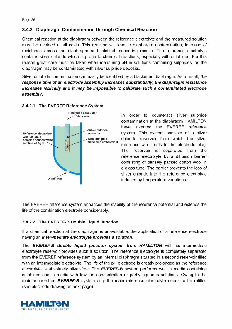
3.4.2.1 The EVEREF Reference System
In order to counteract silver sulphide contamination at the diaphragm HAMILTON have invented the EVEREF reference system. This system consists of a silver chloride reservoir from which the silver reference wire leads to the electrode plug. The reservoir is separated from the reference electrolyte by a diffusion barrier consisting of densely packed cotton wool in a glass tube. The barrier prevents the loss of silver chloride into the reference electrolyte induced by temperature variations.
The EVEREF reference system enhances the stability of the reference potential and extends the life of the combination electrode considerably.
3.4.2.2 The EVEREF-B Double Liquid Junction
If a chemical reaction at the diaphragm is unavoidable, the application of a reference electrode having an inter-mediate electrolyte provides a solution.
The EVEREF-B double liquid junction system from HAMILTON with its intermediate electrolyte reservoir provides such a solution. The reference electrolyte is completely separated from the EVEREF reference system by an internal diaphragm situated in a second reservoir filled with an intermediate electrolyte. The life of the pH electrode is greatly prolonged as the reference electrolyte is absolutely silver-free. The EVEREF-B system performs well in media containing sulphides and in media with low ion concentration or partly aqueous solutions. Owing to the maintenance-free EVEREF-B system only the main reference electrolyte needs to be refilled (see electrode drawing on next page).
Reference conductorSilver wire
Silver chloride reservoir
Diffusion pipefilled with cotton wool
Diaphragm
Reference electrolytewith constant chloride concentration,but free of AgCl

Page 27
3.5 Alkaline and Acid Error
3.5.1 Alkaline Error
At a value above pH 10 the gel layer structure at the membrane of a measuring electrode is subject to certain changes which lead to a measuring inaccuracy, the alkaline error. This alkaline error is caused by the presence of a high concentration of alkaline ions, especially sodium ions (Na+). These ions replace, partly or completely, the hydrogen ions in the outer gel layer of the glass membrane, and by doing so, contribute to the potential at the outer phase boundary.
As a result a lower pH value will be measured than the actual pH value of the measured solution.
In earlier days the alkaline error of glass electrodes already developed between pH 9 and pH 10. Today, where the glass membranes contain lithium instead of sodium, the alkaline error is only noticeable from between pH 12 and pH 13.
The alkaline error increases with increasing pH value, with higher alkaline concentration and with rising temperature.
In order to counteract the alkaline error, electrode manufacturers use special membrane glasses with low alkaline errors for electrodes which are used to measure high pH values.
Electrode Head(Variopin or SMEK)
Refill opening
Intermediateelectrolyte
Reference systemEVERREF-BInternaldiaphragm
External diaphragm
Internal bufferplus KCl
3 mole KCl
Internalconductor electrode (Ag/AgCl)
pH Electrode “Chemotrode Bridge”
with Intermediate Electrolyte
0
50
mV
50
100
150
200
250
300
350
400
1 2 3 4 5 6 7 8 9 10 11 12 13 14
AlkalineError

Page 28
3.5.2 Acid Error
At low pH values (< pH 2) the potential difference between measuring and reference electrode will not conform exactly to the NERNST equation. Through experiments it has been proven that the gel layer of the membrane will absorb acid molecules at very low pH values.
This absorption decreases the activity of the H+ ions and results in a lower potential at the outer membrane phase boundary. The pH measurement shows a higher pH value than the actual pH value of the measured solution. This effect is known as the acid error.
As with the alkaline error, manufacturers supply measuring electrodes with membrane glasses having specially low acid errors.
HAMILTON membrane glasses show no acid error above pH 1.
3.6 Temperature Influence and Temperature Compensation
The pH measurement is temperature dependent. Three temperature factors have to be considered in order to perform a nearly perfect pH measurement:
1. the temperature dependency of the NERNST equation
2. the position of the isotherm intersection point
3. the pH/temperature dependency of the measured solution
The temperature dependency of the Nernst equation and with it the temperature dependency of the theoretical slope of a pH electrode assembly has already been discussed in paragraph 3.1.
The temperature dependency of the NERNST equation is easily calculated, and as a rule, only this temperature influence is considered by instrument manufacturers when they incorporate conventional manual or automatic temperature compensation in their pH measuring products. The adjacent graph illustrates the theoretical error which is compensated for by conventional temperature compensation.
pHmV
+
1 2 3 4 5 6 7 8 9 10 11 12 13 1450
100
150
200
300350
400
450
50
100
150200
300
350400
45065 Co
25 Co
The slope of a pH electrode assembly is temperature dependent in accordance with the NERNST equation.
Slope at 25 C = 59,16 mVo
Slope at 65 C = 67,09 mVo
Theoretical Values
Measuring ErrorwithoutTemperature Compensation
31.72 mV
0,47 pH
Calibration at 25 Co
Measurement at 65 Co
0
50
100
150
200
250
300
350
400
mV+
50
1 2 3 4 5 6 7 8 9 10 11 12 13 14
Acid Error

Page 29
The position of the isotherm intersection point has to be taken into consideration as well. The reason for the existence of the isotherm intersection point and the determination of its position has been explained in paragraph 3.3.5.
Today electrode manufacturers try to produce pH measuring electrodes which have the isotherm intersection point positioned as near as possible to the theoretical zero point (pH 7). This will reduce the residual error of conventional temperature compensation, as instrument manufacturers nowadays omit the Uis potentiometer, which could be found in earlier days on quality pH meters/transmitters. Nowadays only microprocessor based pH meters/transmitters have the capacity to correct the position of the isothermal intersection point (Uis).
The third factor is the pH/temperature dependency of the measured solution which is also called the temperature
coefficient of that solution. The dissociation of molecules is highly temperature dependent. Any change in temperature of the measured solution results in a change in the hydrogen ion concentration of that solution and therefore in its pH value. This pH change is a reality and cannot be described as a measuring error.
The pH/temperature dependency of all acids and bases is not known and it is therefore of utmost importance to state the related temperature when giving a pH value of a solution, otherwise the pH measurement is meaningless.
pHmV
+
1 2 3 4 5 6 7 8 9 10 11 12 13 1450100
150
200
300350
400
450
50
100
150200
300
350400
45065 Co
25 CoSlope at 25 C = 59,16 mVo
Slope at 65 C = 67,09 mVo
Theoretical Values
Measuring Error withTemperature Compensation
Calibration at 25 Co
Measurement at 65 Co
IsothermIntersection
Point
Measuring Error after Temperature Compensation

Page 30
3.7 Various Electrode Shapes
It is not possible to use one electrode shape for every application. More often in the laboratory different electrode shapes are required as there are numerous pH measurement applications. Electrode manufacturers try to cover most of these applications by offering varying electrode constructions.
Form a)
This is the most common electrode shape and a wide field of applications can be covered with this type of electrode, both in the laboratory and in process control. Measuring, reference and combination electrodes are manufactured using this construction.
Form b)
A standard combination electrode construction with a ground sleeve diaphragm. This electrode is mainly used in the laboratory where dirty or strongly contaminated solutions have to be measured. Its application includes non-aqueous media as well. The diaphragm can easily be cleaned by pushing the sleeve upwards. There is a limited use for this construction in process control (be aware of vibration).
Form c)
This construction example includes two electrode features: a ground sleeve diaphragm and a pipe connector. In order to minimise maintenance time and to pressurise the reference electrolyte an external electrolyte reservoir is connected to the electrode via the pipe connector. This electrode construction can be used in the laboratory and in process control, especially for high purity water control in power stations.

Page 31
Form d)
This electrode construction is mainly used in the chemical industry and in biotechnological processes. The electrode features a large electrolyte vessel which is sometimes combined with an intermediate electrolyte vessel. The electrolyte can be pressurised and also sterilised with hot steam. A special electrode holder is required for this electrode. No laboratory application.
Form e)
The above electrode construction is used in the laboratory where small samples have to be measured.
Form f)
The feature of this construction is the flat membrane which enables the operator to measure the pH of surfaces, e.g. skin, leather, paper etc. HAMILTON supplies this electrode with an unbreakable plastic shaft, as it will often be carried around and used with a portable pH meter.
Form g)
This construction is used exclusively for combination electrodes featuring a gel or polymer reference electrolyte. The shaft is made completely from plastic. This design makes the shaft unbreakable as it is often used with a portable pH meter.
Form H)
The above construction, pointed electrode, are normally applied in the food laboratory and in the dairy industry. They facilitate the pH measurement in meat and cheese.

Page 32
3.8 Ageing
3.8.1 The Ageing of a Measuring Electrode
Every glass measuring electrode undergoes an ageing process, even if it is not in use. The ageing process is continuous and starts immediately after manufacture.
Primary reasons for ageing are :
1) the chemical composition of the membrane glass
2) the steady growth of the internal gel layer of the membrane
3) the chemical and mechanical attacks to the outer gel layer of the membrane during measuring and cleaning
Ageing is significantly accelerated by:
1) measurements in hot solutions above 60 °C
2) measurements in high acidity and especially in high alkalinity solutions
3) incorrect handling of electrode assemblies when not in use, i.e. cleaning and storage
Typical symptoms of an aged measuring electrode are:
a) an increased response time
b) an increased membrane resistance
c) a declining slope, especially in the alkaline region
d) a shift of the asymmetry potential
It is of course impossible to state the lifetime of a glass measuring electrode, especially as a combination of the above given reasons for ageing may cause the deterioration of the electrode performance. An electrode, with a potential operating life of 18 months if used continuously in aqueous solution of pH 4 to pH 8 at ambient temperature and if handled correctly, could last only 2 months if operated above at 90 °C. Often an electrode already stops performing after 2 to 3 weeks if it is subjected to high alkalinity of higher than 13 pH and simultaneously at high temperature above 90 °C.
The increasing membrane resistance, the declining slope and the zero point drift (shift of the asymmetry potential) may all be compensated for, within limits, by modern pH meters/transmitters during the calibration process.
A deteriorating response time is a certain indication of ageing. If the response time is unacceptable to the user, then there is no other alternative, but to replace the electrode assembly with a new one.

Page 33
3.8.2 The Ageing of the Reference Electrode
Reference electrodes do not age in principle, but their life may be considerable shortened by incorrect handling, during usage and storage.
The reference electrode always has to be topped-up with an identical electrolyte used originally by the manufacturer, otherwise the reference potential becomes unstable, the response time of the electrode assembly gets sluggish, and in extreme circumstances the entire conducting system may be destroyed.
The diaphragm, being the most critical part of the reference electrode, has to be kept clean at all times. No measuring solution must enter the electrolyte vessel through the diaphragm and all chemical reactions at the diaphragm must be avoided (see paragraph 3.4 The Diaphragm).
Reference electrodes utilizing a gel-electrolyte reduce maintenance cost as they don’t have to be topped-up with liquid electrolyte. Although they are to a certain degree pressure resistant (up to 200 kPa) diffusion over the diaphragm does take place in both direction and will gradually reach the reference system, resulting in electrode poisoning. In addition the KCl concentration in the gel-electrolyte will be diluted over time by the measured media. Both of the above reasons result in a limited life of the reference electrode. High temperature or rapid temperature changes will also shorten the life of a gel electrode. A combination electrode with gel-electrolyte should never be used in media having a temperature higher than 60 °C. A reasonable life span of a gel electrode is approximately 6 months if used under normal condition (pH 2 to 12 at temperatures of 25 °C).
HAMILTON reference electrodes utilizing the POLISOLVE electrolyte can be used in high acidic media down to pH 0. This reference electrode is absolutely maintenance free. Although the temperature limit is raised to 130 °C (conventional polymer electrolytes are limited to 90 °C only), it must be understood that if the electrode is continuously exposed to this high temperature the life span is drastically reduced. Under normal conditions an electrode with POLISOLVE electrolyte may easily be used up to 12 month.

Page 34
3.9 Calibration
No pH electrode assembly can measure more accurately than its calibration accuracy! In order to perform a relatively accurate pH measurement, special care has to be taken when calibrating a pH measuring system.
3.9.1 pH Standard and Technical Buffer Solutions
A prerequisite for an accurate pH calibration is the availability of a suitable buffer solution.
pH buffer solutions are mixtures of weak acids and the salt of these acids with a strong base, or mixtures of weak bases and the salt of these bases with a strong acid. Buffer solutions are characterised by the fact that they resist change to their pH value regardless of additions of small quantities of acids or bases. Their hydrogen ion activity is stable over a wide range of dilution or concentration.
The National Institute of Standards and Technology (NIST) recommends nine different buffer solutions for the exact calibration of pH measuring systems. These buffer solutions also serve as reference points for the pH scale, as it is impossible to prove the activity of single hydrogen ions by measurement.
All buffer solutions which are produced according to the NIST formulas are called Standard Buffer Solutions.
As the activity of the hydrogen ions is temperature dependent, so is the pH value of any buffer solution. The temperature dependency of the NIST standard buffer solutions is given in the table on the following page.
Standard buffer solutions have an accuracy better than +/- 0,005 pH units between 0 °C and 60 °C. Between 60 °C and 95 °C their accuracies are not worse than +/- 0,008 pH units. NIST buffer solutions are exclusively used in laboratories. For industrial use, where the demand on absolute accuracy is normally not as high as in the analytical laboratory, manufacturers offer so-called Technical Buffer Solutions.
Technical buffer solutions are more stable than standard buffer solutions and easier to manufacture. Their accuracies are given as +/- 0,02 pH units in best cases, but differ from manufacturer to manufacturer. The temperature dependency of technical buffer solutions is normally printed on their container by the manufacturer. Conventional technical buffer solutions have a limited shelf-life, most of them only one year in sealed bottles. Once opened, their shelf-life is reduced to a few months. Especially alkaline buffer solutions are affected by CO2 contamination from the atmosphere.
Not so for the new DURACAL pH buffer solutions from HAMILTON. These patented technical buffer solutions provide a pH stability never achieved before; their high accuracies are guaranteed for 5 years after date of manufacture. The pH 9,21 and pH 10.01 buffer solutions are stable even in open air.
Each bottle of HAMILTON buffer solutions is certified, including the actual pH value and expiry date. The certification is traceable to primary standards from NIST and PTB.

Page 35
pH
Va
lue
s o
f St
an
da
rd B
uffe
r So
lutio
nsa
cc
ord
ing
to
NIS
T
Tem
p.
C 0
5 10 15 20 25 30 35 38 40 45 50 55 60 70 80 90 95
Po
tass
ium
tetr
a-o
xal
ate
-1
,668
1,6
701
,672
1,6
751
,679
1,6
831
,688
1,6
911
,694
1,7
001
,707
1,7
151
,723
1,7
431
,766
1,7
921
,806
Po
tas
siu
mh
ydro
gen
tart
rate
- - - - -3
,557
3,5
523
,549
3,5
483
,547
3,5
473
,549
3,5
543
,560
3,5
803
,609
3,6
503
,674
Po
tas
siu
md
ihy
dro
ge
nc
itra
te
3,8
63
3,8
40
3,8
20
3,8
02
3,7
88
3,7
76
3,7
66
3,7
59
3,7
55
3,7
53
3,7
50
3,7
49
3,7
50
3,7
53
3,7
63
3,7
80
3,8
02
3,8
15
Po
tas
siu
mh
ydro
gen
ph
thal
ate
4,0
104
,004
4,0
003
,999
4,0
014
,006
4,0
124
,021
4,0
274
,031
4,0
434
,057
4,0
714
,087
4,1
264
,164
4,2
054
,227
Ph
osp
ha
te
6,9
846
,951
6,9
236
,900
6,8
816
,865
6,8
536
,844
6,8
406
,838
6,8
346
,833
6,8
346
,836
6,8
456
,859
6,8
776
,886
Ph
os
ph
ate
7,5
347,
500
7,4
727,
448
7,4
297,
413
7,4
007,
389
7,3
847,
380
7,3
737,
367 - - - - - -
Bo
rax
9,4
649
,395
9,3
329
,276
9,2
259
,180
9,1
399
,102
9,0
819
,068
9,0
389,
011
8,9
858
,962
8,9
218
,885
8,8
508
,833
So
diu
m c
arb
on
ate
/so
diu
m h
yd
rog
en
car
bo
nat
e
10
,317
10
,245
10
,179
10,
118
10
,062
10
,012
9
,966
9
,925
9
,903
9
,889
9
,856
9
,828
- - - - - -
Ca
lciu
mh
yd
ro-
xid
e
13,4
23
13,2
07
13,0
03
12,8
10
12,6
27
12,4
54
12,2
89
12,1
33
12,0
43
11,9
84
11,8
41
11,7
05
11,5
74
11,4
49
- - - -
NB
SC
od
eA
B
H
C
D
E
F
I
G

Page 36
Stability Comparison of HAMILTON Alkaline Buffer to Conventional Alkaline Buffer
Both buffer solutions have been exposed to blowing air
Used buffer solutions should always be discarded and never be returned to their original storage bottle. For this reason HAMILTON have developed a unique storage bottle which includes a calibration compartment with a non-return valve at the bottom, preventing the used buffer solution to be returned into the storage bottle. This CALPACK bottle is practical: no additional calibration container is required, and it is economical: only the required amount of buffer solution is used.
The Practicality of the HAMILTON CALPACK Calibration Bottle
9,1
9,2
9,3
9,0
8,9
pH
-12 0 12 24 36 48 60 72Hours
HAMILTON DURACAL Buffer 9,2
Conventional Buffer

Page 37
Values and Accuracies of HAMILTON Buffer Solutions
Buffer Solution pH value Accuracy Stability in months
HAMILTON DURACAL 1,09 +/- 0,02 pH 60
HAMILTON DURACAL 1,68 +/- 0,02 pH 60
HAMILTON DURACAL 2,00 +/- 0,02 pH 60
HAMILTON DURACAL 3,06 +/- 0,02 pH 60
HAMILTON DURACAL 4,01 +/- 0,01 pH 60
HAMILTON DURACAL 5,00 +/- 0,02 pH 60
HAMILTON DURACAL 6,00 +/- 0,02 pH 60
HAMILTON DURACAL 7,00 +/- 0,01 pH 60
HAMILTON DURACAL 8,00 +/- 0,02 pH 60
HAMILTON DURACAL 9,21 +/- 0,02 pH 60
HAMILTON DURACAL 10,01 +/- 0,02 pH 60
HAMILTON 11,00 +/- 0,05 pH 24
HAMILTON 12,00 +/- 0,05 pH 24
It must always be remembered: one cannot achieve a better measuring accuracy than the accuracy of the buffer solution one uses for calibration.
3.9.2 The Calibration Procedure
It has been said and explained before that no pH electrode assembly responds ideally to the NERNST potential. The reason lies in the behaviour of the various potential sources of the electrode assembly as well as their response to temperature change and the changes of these parameters with time.
In order to use a single electrode assembly (separate measuring electrode and reference electrode) or a combined electrode assembly effectively and to perform an accurate and repeatable pH measurement, the pH meter/transmitter has to be adapted to the characteristics of the applied electrode assembly.
Please note: it is not the electrode assembly that is calibrated, it is the mV measuring instrument which is adjusted in order to compensate for the imperfection of any utilised electrode assembly. The performance properties of an electrode assembly cannot be changed at will.
The adaptation of the pH measuring instrument to the performance characteristics of the electrode assembly is done by calibrating the pH measuring system (pH electrode assembly plus instrument) against buffer solutions having definite pH values.
There is a difference in the calibration procedure between analogue and microprocessor controlled pH meters. In principle the calibration procedure should be described in the operating instructions supplied with all pH meters/transmitters.
A brief description of the calibration procedure for analogue and microprocessor pH meters follows on the next page.

Page 38
3.9.2.1 Calibration of Analogue pH Meters
1) Two buffer solutions of different pH values have to be selected. The pH value of one buffer solution should be as close as possible to the zero point of the electrode assembly, which is, under normal circumstances, pH 7.
The second buffer solution should have a pH value which lies as near as possible at the end of the anticipated measuring range and the value should differ as much as possible from the zero buffer solution, at least 2 pH units.
If the measuring range covers the acidity and the alkalinity range then a third buffer solution is required. The pH value of the second buffer solution should lie in the acid region and the third buffer solution should lie in the alkaline region of the desired measuring range. Both values should differ as much as possible.
2) The pH value of any buffer solution is temperature dependent. Therefore the temperature of the applied buffer solution has to be measured in order to establish the correct pH value of the buffer solution.
The temperature adjustment potentiometer (manual temperature compensation) must be set to the buffer temperature. With automatic temperature compensation the temperature sensor, connected to the pH measuring instrument, must be immersed into the buffer solution.
Manual Temperature Compensation
Temperature Dependency of
Technical buffer Solutions
0 1 2 3 4 5 6 7 8 9 10 11 12 13 14
pH Scale
HAMILTON Buffer Solutions
ZeroCalibration
SlopeCalibration Verifying
measuring range I
measuring range II
pH4,01
pH7,00 pH
10,01
7,00 pH
oCzero slope
Uis
C HAMILTON Buffer Solutionso
51015182022253035404550
4,014,004,004,004,004,004,014,014,024,034,044,05
7,097,067,047,037,027,017,006,996,986,976,976,97
10,1910,1510,1110,0810,0610,0410,01 9,97 9,92 9,86 9,83 9,79

Page 39
3) After rinsing the electrode assembly with de-ionised water, it is immersed into the first buffer solution for the zero point compensation (normally pH 7 = 0 mV). The electrode assembly has to stay in the buffer solution for a short time, at least for one minute, till the indication of the pH meter settles near the pH value of the buffer solution (pH 7) and becomes stable. Thereafter the indicated value has to be adjusted with the zero potentiometer to the exact value of the buffer solution. The zero potentiometer is sometimes marked @pH or pHas.
For analogue pH meters it is important that the zero point calibration is always performed before the slope calibration.
4) After the zero point calibration, the electrode assembly has to be rinsed again with de-ionised water and dried with tissue paper. When drying the electrode, care must be taken not to rub the membrane, i.e. only dab the electrode with tissue paper. Under no circumstances must an electrode be rubbed. This might introduce static electricity into the glass shaft of the electrode and could make an accurate pH measurement impossible for hours.
5) The electrode assembly is then immersed into the second buffer solution (acid or base – according to the measuring range). After the indication of the pH meter has stabilised, the indicated value has to be adjusted with the slope potentiometer to the exact pH value of the second buffer solution. The slope potentiometer is sometimes marked mV/pH.
It is advisable to re-check the zero point after the slope calibration has been performed.
It is of utmost importance that the above calibration sequence must be adhered to, otherwise no valid calibration will be obtained.
6) If the measuring range covers both the acidity and the alkalinity range the third buffer solution serves as a verifying solution. After the zero point (with the first buffer) and the slope calibration (with the second buffer) has been accomplished, the calibration over the entire measuring range has to be verified with the third buffer solution (be aware of acid and alkaline errors).
7) In order to keep the temperature error as low as possible, especially errors due to the diffusion potential and the isotherm intersection point, it is recommended that the calibration be executed at the temperature at which the actual pH measurement will be performed.
8) After the successful calibration the used buffer solution should be discarded. Never re-use buffer solution and never return it to its original storage container.
No rubbing!
6)
7)
pH 4,01Technical
Buffer
Solution
Page 40
3.9.2.2 Calibration of Microprocessor-based pH Meters
Microprocessor-based pH meters are more and more employed in laboratories and as on-line instruments in industrial plants. Even portable pH meters are nowadays microprocessor controlled. Their handling is relatively simple. Normally the operator is menu-guided through the procedure of his task. These instruments give less reasons for wrong handling and therefore less measuring errors.
The calibration procedure differs slightly from the calibration procedure with conventional analogue pH meters. Although two buffer solutions still have to be used, it is not necessary anymore to calibrate the zero point with buffer 7. The two buffer solutions required should represent the start and the end of the selected measuring span. The zero point, the slope and even the isotherm intersection point are all determined by the microprocessor during the different stages of calibration.
In general the calibration is performed as follows:
1) Two buffer solutions of different pH values have to be selected. The pH value of one buffer solution should lie somewhere in the region of the beginning of the desired measuring span and the pH value of the second buffer solution should lie somewhere at the end of the measuring span.
After the calibration mode of the pH meter is activated, the calibration menu guides the operator through the calibration procedure. Sometimes the buffer values still have to be entered manually, very often the microprocessor identifies the buffer values automatically.
2) The temperature of the buffer solutions has to be measured, either with the incorporated temperature sensor in the pH electrode or separately with a glass thermometer. The temperature values are either entered manually into the microprocessor or, with an incorporated electrode sensor, detected automatically.
The electrode handling is identical to the electrode handling during the calibration procedure of analogue pH meters as explained in point 3) and 4) of paragraph 3.9.2.1.
3.9.3 Re-calibration
The pH calibration has to be repeated periodically. The time interval between calibrations cannot be specified. This depends on various factors:
a) the measured pH value
b) the measured solution
c) the temperature of the measured solution
d) the age of the electrode assembly
e) the accuracy required
The calibration interval can vary between hours, days, weeks or even months, and has to be established individually for each application. When working with unknown process liquids, it is advisable to initially re-calibrate as often as possible. If no significant change of the calibration values is noticed, the frequency of the calibration may be progressively extended.

Page 41
The Frequency of re-calibration has to be established experimentally
CalibratepH !
CalibratepH !
CalibratepH !
CalibratepH !
CalibratepH !
CalibratepH ! CalibratepH !
May 2002
3.9.4 Response Time
If a pH electrode assembly is immersed into a buffer solution, it does not show the pH value of that buffer solution instantaneously. A response time of approximately 30 seconds is normal in order to reach the buffer value with a tolerance of 0,01 pH units (0,6 mV). For this reason it is very important to wait long enough during the calibration cycle for the indication of the pH meter to become stable. Only then can the indicated value be adjusted to the buffer value. A premature interruption of the electrode adaptation to the buffer value is often a major source for incorrect pH measurements.
The response time of an electrode assembly is especially slow if the electrode temperature and the temperature of the buffer solution differ by more than 10 °C. In cases where buffer solutions have to be heated, one has to delay the calibration procedure until the electrode reaches the temperature of the heated buffer solution.
A further point to consider is the storage medium used for electrode assemblies. Never store pH electrode assemblies which are not in use, in distilled water, as this will slow down the response time of that electrode assembly considerably. It has been found that a 3 mole KCl solution is the best storage medium for glass electrode assemblies.
Modern microprocessor based pH meters/transmitters are fitted with a programme for early detection of a stabilised calibration value (Auto-Read). Verification measurements have shown that the Auto-Read values do not differ more than 0,01 pH units from the end value of the adapted electrode assembly when dealing with new electrodes.
3.9.5 Reasons for calibration problems
Three common problems might be encountered when calibrating a pH measuring system. These are:
1) difficulty in achieving a zero point calibration
2) no success in obtaining a slope calibration
3) a very long response time (longer than 3 minutes)

Page 42
There could be various reasons for the above mentioned problems. The most frequent ones are listed below:
a) the utilised buffer solutions are either contaminated or out-dated. It could be that the buffer solution used is incorrect – therefore never store buffer solutions in unmarked bottles
b) the electrolyte of the reference electrode is contaminated and/or the diaphragm is blocked
c) a time-worn electrode assembly is utilised
d) an electrode assembly is utilised which has not been hydrated long enough (after dry storage or after cleaning with an acid solution)
e) hair cracks are present in the membrane of the measuring electrode
f) electrostatic charge on the electrode assembly caused by rubbing the electrode shaft with cloth instead of gently dabbing it with tissue paper
g) a temperature difference between electrode assembly and buffer solution of more than 10 °C
h) the zero point of the pH electrode assembly and the measuring instrument differ. This is seldom the case as normally both have pH 7 as their zero potential. In exceptional cases the pH electrode assembly could have a zero point which differs from pH 7
i) the connection between electrode assembly and measuring instrument could also cause problems: either open-circuit in the cable or short-circuit in cable and/or connection plug (usually due to moisture ingress)
3.10 The Accuracy to be Expected
The accuracy of a pH measurement depends on many factors of which some cannot be controlled while others can. In order that the non-controllable factors do not influence the result of the pH measurement to too great a degree, the controllable factors must be monitored and kept as small as possible.
The calibration of the pH measuring system is one of the most important factors. To ensure a high measuring accuracy one has to follow the correct calibration procedure, use new and accurate buffer solutions and wait long enough for stable indication values of the electrode assembly to be calibrated. The time interval between re-calibration should be as short as practically possible. Remember: no pH measurement can be more accurate than its calibration accuracy.
It has been stated repeatedly that temperature influences the result of the pH measurement. In order to achieve high measuring accuracies the temperature difference between the buffer solutions used for calibration and the measured medium must be kept as low as possible. The temperature of the measured medium must be measured accurately or, if possible, controlled at a constant value in order to perform an effective temperature compensation.

Page 43
The reference electrode must be kept pressurised by approximately 100 kPa (1 bar) above the pressure of the measured medium to keep the reference electrolyte flowing and prevent the ingress of measured solution into the reference electrolyte vessel. The diaphragm must be kept clean at all times. The correct matching of the diaphragm type to the measuring problem will drastically improve the measuring accuracy.
The conducting system and electrolyte of measuring and reference electrode must be identical.
The membrane of the measuring electrode must also be kept clean at all times. Deposits on the membrane glass will reduce the measuring accuracy dramatically and in extreme cases make a pH measurement impossible.
Accuracy expectations should not exceed practical achievable results. Realistic accuracies of between +/- 0,03 pH units and +/- 0,05 pH units can be achieved with a well hydrated and intact electrode assembly connected to an accurate, state-of-the-art pH measuring instrument having the required high impedance of at least 1012 ohms. In the laboratory accuracies of +/- 0,02 pH units are achievable.
4 ELECTRODE HANDLING
pH measuring systems are by nature maintenance intensive. Most of the maintenance activities are mainly concentrated towards the pH electrode assembly, e.g. calibration and cleaning. The correct handling of the electrode assembly during the maintenance period is of utmost importance to the ideal functioning of the entire pH measuring system.
Incorrect handling might shorten the life of the electrode assembly considerably or cause an unreliable measuring result. Correct handling of the pH electrode assembly does not only improve the measuring result, it can also save the plant owner a substantial amount of money.
4.1 Storage
When considering the storage of a pH electrode assembly, one has to differentiate between the types of electrodes: measuring electrode, reference electrode or combination electrode. The time of storage must also be taken into account, i.e. long-term storage for weeks or months, or short storage intervals between measurements.
4.1.1 The Storage of Measuring Electrodes
Measuring electrodes can be stored dry for long periods. However before using the measuring electrode it has to be hydrated for at least 48 hours in normal tap water or a slightly acidic solution in order to establish an outer gel layer at the pH sensitive membrane.
Nevertheless, in order that the electrode is ready for immediate use, most manufacturers supply their measuring electrodes hydrated, i.e. a plastic or rubber cap filled with a liquid solution is placed over the membrane. It is essential that this cap is kept filled at all times. The filling liquid is either tap water or a weak acidic solution. This will keep the membrane hydrated and therefore the outer gel layer well developed.

Page 44
If a measuring electrode has to be stored for short periods between measurements it should be immersed in a container filled with tap water or be fitted with a watertight plastic cap filled with tap water. Therefore one should not throw the supplied plastic caps away. They should be kept for re-use.
4.1.2 The Storage of Reference Electrodes
Reference electrodes should always be stored wet, i.e. the diaphragm has to be covered with the same reference electrolyte with which the reference electrode has been filled. Wet storage must also be applied when the electrode is stored for a long time.
It is not advisable to store reference electrodes dry as the reference electrolyte will slowly penetrate through the diaphragm and crystallise and subsequently cover the complete bottom of the electrode. The crystallisation itself does not cause a problem but the reference electrode might dry out completely which will result in a substantial increase in the diaphragm resistance. Even when the reference electrode is refilled with its respective electrolyte, the high diaphragm resistance will not disappear immediately and will result in large measuring errors or even make a measurement totally impossible.
Therefore for short or long periods of time it is essential to store reference electrodes in their respective reference electrolyte, with the refill aperture closed by a suitable stopper.
Storage in tap water or in distilled water should be avoided. Any penetration of these liquids through the diaphragm will increase the diaphragm potential considerably and will significantly falsify the subsequent pH measurement.
4.1.3 The Storage of Combination Electrodes
A combination electrode consists of a measuring electrode and a reference electrode combined into one single-rod electrode. The storage conditions must therefore be suitable for a measuring and for a reference electrode. As every reference electrolyte is an aqueous solution it has been found that the optimum storage liquid is the respective reference electrolyte of that combination electrode. The refill aperture has to be closed during storage time.
All that has been stated about the storage of a reference electrode applies equally to the storage of a combination electrode.
Gel-filled combination electrodes are an exception to the rule. These electrodes have no refill aperture and the drying-out of their diaphragm has to be avoided at all costs. Therefore gel-filled combination electrodes must be stored wet in a 3 mol/l KCl solution.
This statement applies to polymer electrodes as well.
Closed refill aperture
Rubber or plastic capfilled withreference electrolyte ( 3 mol/l KCl)
KCl3 mol/l

Page 45
4.2 Cleaning of Electrode Assemblies
Industrial pH electrode assemblies are often immersed into process solutions which tend to contaminate the membrane of the measuring electrode or the diaphragm of the reference electrode or both. The result is one, or a combination of the following:
a) a zero point shift
b) a reduced slope
c) a long response time
Principally the electrode assembly has to be clean at all times in order to guarantee an ideal pH measurement. Therefore the periodic cleaning of the electrode assembly should be part of any regular plant maintenance schedule. As the cleaning frequency depends solely on the measuring solution, a cleaning time cycle has to be established individually for each pH measuring application. The cleaning interval could vary between hours and weeks.
The cleaning procedure also depends on the kind of contamination. The following procedures have been found practical and effective:
Initially always try to remove any deposits from the membrane or from the diaphragm by rinsing the electrode with a mild detergent.
Calcium deposits may be removed by soaking the electrode for several minutes in a solution of 0,1 mol/l HCl.
To remove oil and fat deposits the use of a strong household solvent is recommended. If this is unsuccessful a brief rinsing in ethyl alcohol is advisable.
Measuring solutions containing proteins tend to contaminate the membrane and diaphragm of the electrode assembly. Soaking the electrode assembly for several hours in a solution of 1% pepsin in 0,1 mol/l HCl is normally a remedy.
Inorganic coatings can be removed using commercially available glass cleaning solutions.
Measuring solutions containing sulphides will react with the silver chloride present in most reference electrolytes. This reaction will lead to the contamination of the diaphragm with silver sulphide deposits (black diaphragm). To remove the silver sulphide deposit the electrode has to be soaked in a thiourea/HCl solution until the diaphragm is totally bleached.
Highly resistant deposits may be removed with hydrogen peroxide or sodium hypo-chloride.
Any other acid or alkaline soluble deposits may be removed by either rinsing the electrodes in 0,1 mol/l HCl or in 0,1 mol/l NaOH for a few minutes only.
It is very important that after each above mentioned cleaning process the cleaned electrode has to be soaked in its respective reference electrolyte (normally 3 mol/l KCl) for at least 12 hours, or preferably a day (hydration process). As the cleaning solution may have penetrated the diaphragm which will change the diffusion potential, it is absolutely necessary to perform a re-calibration after the soaking time in the reference electrolyte and before a new pH measurement takes place with the cleaned electrode (see paragraph 3.8)

Page 46
During the cleaning process the electrode should only be rinsed or soaked. Under no circumstances must an electrode be cleaned mechanically, i.e. with a knife, screwdriver or any other sharp tool as this might destroy the electrode. Rubbing with a cloth must also be avoided as this will introduce static electricity into the glass shaft of the electrode and prolong the response time considerably (see paragraph 3.8.2).
4.3 Refilling or Replacing the Reference Electrolyte
A reference electrode or a combination electrode utilising a liquid reference electrolyte has to be inspected at regular time intervals to check its electrolyte level. The electrolyte has to be replenished when the internal reference system is no longer fully covered by the electrolyte. The topping up is done by injecting a corresponding reference electrolyte through the refill aperture. This can easily be done by using a pipette or syringe.
If the reference electrolyte is contaminated by the ingress of the measured medium or if the concentration of the reference electrolyte has been increased through the evaporation of water, the reference electrolyte should be replaced completely.
HAMILTON supplies a brief operating and maintenance instruction for each of their electrodes . Please observe these instructions – they could save you a great amount of trouble, frustration and a lot of money.
5 THE CONNECTION OF THE pH ELECTRODES TO THE pH MEASURING INSTRUMENT
5.1 Measuring Electrode Connection Cable
The pH measuring electrode has inherently a high internal resistance (up to 5x10⁹ ohms in some cases) and, therefore the electrical connection to a pH meter or transmitter is prone to all kinds of electro-magnetic interference. For this reason special and high demands are made to the quality of the cable which connects the pH measuring electrode to its measuring instrument.
A measuring electrode is always connected with a low-noise screened coaxial cable to the measuring instrument. This cable must have a very high insulation resistance, always higher than the input impedance of the measuring instrument (normally 1012 ). The market offers coaxial cables having an insulation resistance of 1014 to 1017 per metre cable length.
Another specification to observe is the cable capacitance. This should be as low as possible in order not to increase the time constant of the signal transmission. Experience has shown that the capacitance of a pH connection cable should not be higher than 150 pF/m. A 200 pF/m cable capacitance on a 50 m long cable would add approximately 50 seconds time delay to the response time of the electrode assembly. Coaxial cables available for pH measurements have a capacitance of between 64 pF/m to 102 pF/m.
The temperature rating of the pH connection cable also has to be considered. For normal measuring applications below 70 °C, standard pH connection cables have a temperature rating of –30 °C to +80 °C. Special high temperature cables are available having a maximum temperature rating of 130 °C.

Page 47
5.2 Reference Electrode Connection Cable
The connection of a separate reference electrode to the measuring instrument is not problematic, as long as the cable is protected from any electro-magnetic interference. Normally a standard single core, screened cable suffices. Temperature ratings of the cable must be observed.
5.3 Combination Electrode Connection Cable
What has been said about the cable requirements for a separate measuring electrode must also be observed for the connection of a combination electrode. It is advisable to use a double screened coaxial cable (triax cable). To save costs it is normal practice to connect the inner screen of the coaxial cable to the reference electrode part of the combination electrode.
5.4 Cable Preparation and Cable Routing
The insulation of the internal conductor of a pH connection cable is not only screened with copper wire mesh but also with an additional black semiconductor layer. This layer suppresses voltages which might be created when moving the coaxial cable. It is of importance that this black layer must be carefully removed when preparing the cable ends for connection to the electrode plug and/or to the measuring instrument. If the black layer is not removed, it will cause a short circuit between the internal conductor and the copper screen. When stripping the coaxial cable, tools and hands of the technician should always be dry and clean. After stripping, the cable ends should be cleaned with alcohol or ether, which can be done with a cloth or a brush, both of which should be absolutely clean. Touching the stripped cable ends with wet or fat-stained fingers will reduce the insulation resistance down to, or below, 107 ohms, which will result in a short circuit of the high resistance measuring chain – a pH measurement becomes impossible.
When routing the pH connection cable care must be taken not to route the pH connection cable parallel to power cables. Parallel situated power cables in the vicinity of the pH connection cables would lead to electro-magnetic interference (induction), which must be avoided at all cost. The outer screen of the triax cable (combination electrode) should always be earthed on one side only. In principle, every pH connection cable should be as short as possible, but should under no circumstance be longer than 50 metres.
pH connection cables cannot be buried straight into the ground. If this has to be done these cables must be installed in a metal or plastic conduit.
Coaxial cable Triax cable
internal conductor
PE insulation
black semiconductor layer
screen
PVC external insulation
black semiconductor layer
internal conductor
PE insulation
screen 1
screen 2
PVC external insulation PVC
insulation

Page 48
5.5 Plug or Cable?
Various electrode manufacturers supply their pH electrodes in two configurations: either with an integrally installed cable (normally 1 metre in length), or with an electrode plug connection. Both configurations have their advantages and disadvantages.
If the cable is installed to the electrode by the manufacturer, the customer can be assured that the cable connection is water tight and measuring faults attributed normally to the electrode/cable connection (short circuit, moisture ingress) can be ruled out. On the other hand however, when the pH electrode assembly has to be replaced (remember: a pH electrode is a consumable item with a certain life expectancy), the cable also has to be re-purchased.
An electrode plug connection eases the electrode removal or replacement during the maintenance period and is more economical in the long run (saving of cable cost). However, care must be taken to always connect the electrode socket firmly to the cable plug, otherwise moisture, the biggest enemy to the electrode/cable connection, might penetrate the socket/plug coupling. Once moisture has entered this joint, a reliable pH measurement is no longer possible.
Electrode head with integrated cable
and different instrument plugs
Electrode socket – cable plug connection

Page 49
6 Appendix: THE HYDROGEN ION CONCENTRATION
Before the term pH can be defined, certain chemical and physical principles have to be described, central of which will be the water molecule with its two hydrogen atoms (H2) and its one oxygen atom (O).
6.1 The Atom Structure
In ancient Greek philosophy the word atom was used to describe the smallest bit of matter that could be conceived. This fundamental particle, to use the present-day term for this concept, was thought of as indestructible; in fact, the Greek word for atom “atomos” means “not divisible”. Knowledge about the size and nature of the atom grew very slowly throughout the centuries as people were content merely to speculate about it.
With the advent of experimental science in the sixteenth and seventeenth centuries, progress in atomic theory accelerated. Chemists soon recognised that all liquids, gases and solids could be analysed into their ultimate components, or elements. For example, salt was found to be composed of two distinct and different elements: sodium and chlorine, which are joined together in an intimate bond known as a chemical compound.
The atoms are the building blocks of an element. All atoms of any given element behave chemically in the same way. Thus, from a chemical viewpoint, the atom is the smallest entity to be considered. The chemical properties of the various elements are quite different; their atoms combine in many different ways to form a multitude of different chemical compounds. There are as many different atoms as there are elements. Today we know of 112 different elements.
In 1911 the British physicist Ernest Rutherford (1871 – 1937) formulated a theory of atomic structure that was the first visualisation of the atom as a dense nucleus surrounded by a cloud of electrons. Rutherford established that the mass of the atom is concentrated in its nucleus. The nucleus has a positive charge of electricity; the electrons each have a negative charge. The charges carried by the electrons add up to the same amount of electricity as resides in the nucleus, and thus the normal electrical state of the atom is neutral. Rutherford called the particles, forming the nucleus, protons. Rutherford’s vision of an atom was revised in 1913 by Niels Bohr (1885 – 1962) (see next paragraph “The Bohr Atom”).
In 1932, another British physicist James Chadwick (1891 – 1974), discovered another particle in the nucleus of an atom , known as the neutron, having the same mass as the proton but without an electric charge. It was then realised that the nucleus is made up of protons and neutrons. In any given atom, the number of protons is equal to the number of electrons and hence to the atomic number of the atom (its position in the “Periodic Table of the Elements”).
6.2 The Bohr Atom
To explain the structure of the atom, The Danish physicist Niels Hendrik David Bohr developed in 1913 a hypothesis known as “The Bohr Theory of the Atom”. He assumed that electrons are arranged in definite shells, or quantum levels, at a considerable distance from the nucleus. The arrangement of these electrons is called the electron configuration.

Page 50
The Bohr Atom
The number of such electrons equals the atomic number of the atom: hydrogen has a single orbital electron, oxygen has 8, and uranium has 92.
The electron shells are built up in a regular fashion from a first shell to a total of seven shells, each of which has an upper limit of the number of electrons that it can accommodate. The shells are named from inner shell to outer shell: K-shell, L-shell … to Q-shell. The K-shell is complete with two electrons, the L-shell can hold up to eight electrons, the M-shell 18 electrons and in general the nth shell 2n2 electrons. Only the electrons in the outer shell determine the chemical behaviour of the atom.
Atomic shells do not necessarily fill up with electrons in consecutive order. The electrons of the first 18 elements in the periodic table are added in a regular manner, each shell being filled to a designated limit before a new shell is started.
Starting with the 19th element, the outermost electron starts a new shell before the previous shell is completely filled. A regularity is still maintained, however, as electrons fill successive shells in a repetitive back-and-forth pattern. The result is the regular repetition of chemical properties for atoms of increasing atomic weight that corresponds to the arrangement of the elements in the periodic table.
The Oxygen Atom
The Hydrogen Atom
Nucleus
22x4 = 32 electrons
2
2
2
2x5
2x6
2x7
= 50 electrons
= 72 electrons
= 98 electrons
KLM
Electron
maximum 7 shellsShells
OPQ
N
In each shell thereare 2 n electrons2
The Bohr Atom

Page 51
6.3 The Periodic Table of Elements
In 1869 the Russian chemist Dmitri Ivanovich Mendeleyev (1834 – 1907) arranged all elements known at the time in a table according to their atomic mass. By doing so, he discovered that certain properties of the elements repeat themselves periodically. Therefore Mendeleyev grouped the elements with similar chemical activities in the same columns underneath each other. This element arrangement is called the periodic table.
Over the years more and more elements were discovered and the periodic table had to be rearranged a few times. The table, as we know it today, is illustrated on page 50. The elements are arranged by their ascending atomic number (number of protons in the nucleus) horizontally in seven rows. Each row represents one of the seven electron shells of the atom. Hydrogen in position 1 in row 1 is the lightest element. The last element in the table is, for the time being, the artificial element “ununbium”, taking the 112th position with an atomic mass of 277. The table provides for a total of 118 elements. The 18 vertical columns group the elements according to their chemical activities, i.e. the numbers of electrons in their outer shell.
6.4 The Molecule
The molecule is the smallest unit of a chemical compound having the same chemical properties of that compound. The water molecule consists of a single atom of oxygen and two atoms of hydrogen joined by an electrical force called a chemical bond.
It was the French chemist Antoine Laurent Lavoisier (1743 – 1794) who proved that water was not a basic element, as the ancient philosophers thought, but a compound of oxygen and hydrogen – as expressed by the present-day formula H2O.
Molecules are held together by sharing two electrons (covalent bonds). In order to maximise these bonds, the atoms adopt specific positions relative to each other, i.e. each molecule has its own definite structure. For instance in the water molecule two hydrogen atoms are bonded to the oxygen atom at an angle of 104,5°. Therefore water has a dipole moment as the hydrogen electrons are attracted slightly towards the nucleus of the larger oxygen atom. In contrast the
structure of CO2 is linear and has therefore no dipole moment.
Certain elements do not combine with other elements. These are the group of noble gases. Their atoms contain either 2 electrons (He) or 8 electrons (Ne; Ar; Kr; Xe and Rn) in their outer shell. Any other element having less than 8 electrons in its outer shell will form a bond with other “non-noble” elements.
The stated theory of noble gases does not hold good any more – at least not for the three heaviest noble gases: krypton, xenon and radon. Since 1962 scientists have succeeded in producing certain compounds involving Kr, Xe and Rn. But with the aid of this theory the phenomenon of the chemical bond can be explained.

Page 52
Perio
dic
Ta
ble
of th
e E
lem
ents
H LiBe
Na
Mg
He
Ne Ar
Kr Xe Rn
BC
NO
F
Al
SiP
SC
l
Ga
Ge
As
Se
InSb
Br
SnTe
I
TlBi
PoPb
At
ZnC
uN
iC
oFe
Cd
Ag
PdRh
Ru
Hg
Au
PtIr
Os
K Rb Cs
Ca
Sr Ba
ScTi
V
YZr
Nb
Hf
Ta
Cr
Mo
Mn
Tc
WRe
Hs
Mt
Uun
Uuu
Uub
BhSg
Db
RfRa
Fr
LuYb
TmEr
Ho
Dy
LrN
oM
dFm
EsC
f
TbG
dEu
SmPm N
pA
mBk
Cm
Pu
LaC
eN
dPr
UPa
ThA
c
1 3 11 19 37 55
4 12
2
78
910
15
16
17
18
56
13
1
4
32 3
3
34
36
35
50
5
1 5
2
53
54
82
8
3
8
4
8
5 8
6
27
28
2
9 3
0 3
1
45
4
6 4
748
4
9
77 7
8
79
80 8
1
20 2
122
2
3
25
26
38
3940
24
41
42
43
44
56
72
73
74
75
76
106
107
108
109
110
111
112
88
104
105
87
57
58
5
9 6
061
62
89
9192
9394
63
64
6
566
67
6
8 6
9
95
96
97
98
99
100
70
71
101
102
103
Gas
Liq
uid
So
lid
Syn
thet
ical
lyp
rep
ared
IA
IIA
IIIA
IVA
VA
VIA
VIIA
VIII
AIB
IIB
IIIB
IVB
VB
VIB
VII
B
VIII
BG
rou
p
1.0
079
4.00
26
6.94
19.
0121
8
22.9
897
24.3
05
39.
098
40
.08
44.9
56
47.9
50.9
42
51.9
96
54.
938
55.8
47
58.9
33
5
8.7
6
3.5
46
65
.38
69
.72
72.5
9
7
4.9
22
78
.96
79.
9
83.
8
10.
81
12.
011
14.
006
7
15.
999
4
18.
99
84
20.
179
26.9
82
28
.086
30
.97
4
32
.06
35.
453
39.
948
85.4
68
87
.62
88
.906
9
1.22
92
.90
6
95.9
4
(98)
1
01.0
7
102.
9
106
.4
107.
87
112
.41
114
.82
11
8.6
9
121
.75
1
27.6
1
26.9
1
31.3
132
.9
137
.3
1
78.
5
(223
)
2
26.
0(2
61)
18
0.9
18
3.9
1
86
.2
190
.2
192
.22
1
95.
09
196
.97
200
.59
204
.37
20
7.2
20
8.9
8
(
209
)
(210
)
(2
22)
(26
2)(2
63)
138
.9
14
0.1
1
40
.9
144
.2
227
.03
232
.04
231
.04
90
238
.03
(1
45)
150
.4
151
.96
157
.25
23
7.05
(
244
)
(2
43)
(
247
)
158
.93
1
62.5
16
4.9
3
1
67.
26
(2
47)
(
251
)
(2
52)
(25
7)
168
.93
17
3.04
17
4.9
7
(258
)
(2
59
)
(2
60)
Hyd
rog
en
Lit
hiu
mB
eryl
lium
So
diu
mM
agn
esiu
m
Po
tass
ium
Cal
ciu
mS
can
diu
m
Ru
bid
ium
Str
on
tiu
mY
itri
um
Cae
siu
mB
ariu
m
Fra
nci
um
Rad
ium
Tit
aniu
mV
anad
ium
Ch
rom
ium
Man
gan
ese
Zir
con
ium
Nio
biu
mM
oly
bd
enu
m
Haf
niu
mTa
nta
lum
Tun
gst
enR
hen
ium
Tech
net
ium
Iro
nC
ob
alt
Nic
kel
Co
pp
er
Ru
then
ium
Osm
ium
Irid
ium
Rh
od
ium
Pal
lad
ium
Silv
er
Pla
tin
um
Go
ld
Zin
c G
alliu
mG
erm
aniu
mA
rsen
icS
elen
ium
Cad
miu
mIn
diu
mT
inA
nti
mo
ny
Tellu
riu
m
Mer
cury
Th
alliu
mL
ead
Bis
mu
thP
olo
niu
m
Bro
min
eK
ryp
ton
Iod
ine
Xen
on
Ast
atin
eR
ado
n
Hel
ium
Nit
rog
enO
xyg
enF
luo
rin
eN
eon
Ph
osp
ho
rus
Su
lfu
rC
hlo
rin
eA
rgo
n
Bo
ron
Car
bo
n
Alu
min
ium
Sili
con
Ru
ther
-fo
rdiu
mD
ub
niu
mS
eab
org
ium
Lan
than
um
Cer
ium
Pra
seo
dym
ium
Neo
dym
ium
Pro
met
hiu
m
Act
iniu
mT
ho
riu
mP
rota
ctin
ium
Ura
niu
mN
eptu
niu
m
Sam
ariu
mE
uro
piu
mG
ado
liniu
mTe
rbiu
mD
ysp
rosi
um
Plu
ton
ium
Am
eric
ium
Cu
riu
mB
erke
lium
Cal
ifo
rniu
m
Ho
lmiu
m
Ein
stei
niu
mF
erm
ium
Erb
ium
Th
uliu
m
Men
del
eviu
m
Yit
erb
lum
No
bel
ium
Lu
teti
um
Law
ren
ciu
m
Bo
hri
um
Has
siu
mM
eitn
eriu
mU
nu
n-
Un
un
-U
nu
n-
nili
um
biu
mu
niu
m
(26
2)(2
65)
(266
)(2
69)
(27
2)(2
77)
No
ble
Gas
es
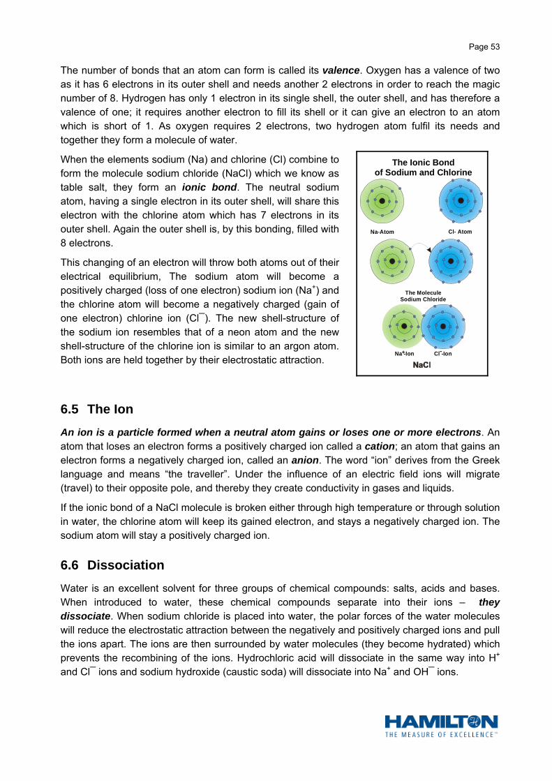
Page 53
The number of bonds that an atom can form is called its valence. Oxygen has a valence of two as it has 6 electrons in its outer shell and needs another 2 electrons in order to reach the magic number of 8. Hydrogen has only 1 electron in its single shell, the outer shell, and has therefore a valence of one; it requires another electron to fill its shell or it can give an electron to an atom which is short of 1. As oxygen requires 2 electrons, two hydrogen atom fulfil its needs and together they form a molecule of water.
When the elements sodium (Na) and chlorine (Cl) combine to form the molecule sodium chloride (NaCl) which we know as table salt, they form an ionic bond. The neutral sodium atom, having a single electron in its outer shell, will share this electron with the chlorine atom which has 7 electrons in its outer shell. Again the outer shell is, by this bonding, filled with 8 electrons.
This changing of an electron will throw both atoms out of their electrical equilibrium, The sodium atom will become a positively charged (loss of one electron) sodium ion (Na+) and the chlorine atom will become a negatively charged (gain of one electron) chlorine ion (Cl¯). The new shell-structure of the sodium ion resembles that of a neon atom and the new shell-structure of the chlorine ion is similar to an argon atom. Both ions are held together by their electrostatic attraction.
6.5 The Ion
An ion is a particle formed when a neutral atom gains or loses one or more electrons. An atom that loses an electron forms a positively charged ion called a cation; an atom that gains an electron forms a negatively charged ion, called an anion. The word “ion” derives from the Greek language and means “the traveller”. Under the influence of an electric field ions will migrate (travel) to their opposite pole, and thereby they create conductivity in gases and liquids.
If the ionic bond of a NaCl molecule is broken either through high temperature or through solution in water, the chlorine atom will keep its gained electron, and stays a negatively charged ion. The sodium atom will stay a positively charged ion.
6.6 Dissociation
Water is an excellent solvent for three groups of chemical compounds: salts, acids and bases. When introduced to water, these chemical compounds separate into their ions – they dissociate. When sodium chloride is placed into water, the polar forces of the water molecules will reduce the electrostatic attraction between the negatively and positively charged ions and pull the ions apart. The ions are then surrounded by water molecules (they become hydrated) which prevents the recombining of the ions. Hydrochloric acid will dissociate in the same way into H+ and Cl¯ ions and sodium hydroxide (caustic soda) will dissociate into Na+ and OH¯ ions.
Na-Atom Cl- Atom
The MoleculeSodium Chloride
Na -Ion+ Cl -Ion
The Ionic Bondof Sodium and Chlorine

Page 54
The dissociation of salts, acids and bases in water causes the water to become an excellent conductor. The resulting solutions are therefore called electrolytes.
If two electrodes are immersed into an electrolyte and a potential difference is applied to these electrodes, the negatively charged ions will be attracted by the positively charged electrode (anode) and by reaching the anode will lose their charge (lose electrons). Hence the name anion. Similarly the positively charged ions will move towards the negatively charged electrode (cathode) and lose their charge by gaining electrons (cation).
6.7 Acids – Bases – Salts
In chemistry we differentiate between three electrolytes: acids, bases and salts.
Acids are chemical compounds which, when dissolved in water, produce a concentration of hydrogen ions, H+ (protons), greater than that of pure water. An acid is therefore a proton donor (proton = positively charged hydrogen ion H+).
Acids taste sour and turn litmus red. Litmus is the oldest and most often used indicator of whether a solution is an acid or a base. It is a pink dye derived from licheus, a plant organism composed of a fungus and an alga in symbiotic association.
ClCl
Cl
Cl
Cl
Cl
Cl
Cl
Cl
H+
H+
H+
H+
H+
H+
H+ H+
H+
+
AnodeCathode
Electrolyte
Na -Ion+
Cl -Ion
The Dissociation of Sodium Chloride

Page 55
The most common acids are:
Hydrochloric acid HCl Component of gastric juices
Nitric acid HNO3 Used to manufacture dyes and explosives
Acetic acid CH3COOH Vinegar
Formic acid HCOOH Used for dyeing and tanning
Sulphuric acid H2SO4 Batteries
Phosphoric acid H3PO4 Dental cement, fertilizer
Bases are chemical compounds which, when dissolved in water, produce an excess of hydroxyl ions, OH¯ or accept protons – a base is a proton acceptor. Bases taste bitter and turn litmus blue. A base feels slimy. The most common bases are:
Sodium hydroxide (caustic soda) NaOH Drain and oven cleaner
Calcium hydroxide Ca(OH)2 Slated lime (used in mortar for construction)
Aluminium hydroxide Al(OH)3 Raw material for aluminium compounds
Potassium hydroxide (potash lye) KOH Soft soap
Magnesium hydroxide Mg(OH)2 Milk of magnesia
Ammonia NH3 Household cleaners
Salts: When aqueous solutions of an acid and a base are combined, a neutralisation reaction occurs. This reaction takes place very rapidly and generally produces water and a salt. For example, sulphuric acid (H2SO4) and sodium hydroxide (NaOH), yield water and sodium sulphate (Na2SO4).
H2SO4 + 2NaOH = 2H2O + Na2SO4
Salts are produced by substituting the H+ ion with a base part or by substituting the OH¯ ion with an acid part. Cations and anions combine to form an electrically neutral compound.
Examples:
Sodium nitrate NaNO3 = Na++NO3-
Aluminium sulphate Al2(SO4)3 = 2Al3++3SO42-
Calcium phosphate Ca3(PO4)2 = 3Ca2++2PO43-

Page 56
6.8 The Mole
“The mole is the SI unit of an amount of substance equal to the quantity containing as many elementary units as there are atoms in 0,012 kg (12g) of carbon-12. The elementary entities must be specified and may be atoms, molecules, ions, electrons or other particles. The unit was established in 1971 for international use.”
(The Oxford Dictionary)
The number of elementary particles contained in 12g of carbon-12 (the atom against which other substances are measured) is 6,0221367 x 10²³. This number is known as the Avogadro’s number in honour of the Italian physicist Amedeo Avogadro (1776 – 1856). Avogadro postulated in 1811 that equal volumes of gases, at equivalent temperatures and pressures, contain the same number of molecules.
A mole, then, is an amount of any substance that weighs, in grams, as much as the numerically equivalent atomic weight of that substance.
1 mole H2 = 2 g
1 mole H2O = 18 g
1 mole Cl2 = 71 g
1 mole Rn = 222 g
1 mole HCl = 36,5 g
1 mole NaOH = 40 g
6.9 The Hydrogen Ion Concentration in Aqueous Solutions
Not only does water dissolve electrolytes and further their dissociation, but a small amount of water molecules dissociate as well into positively charged hydrogen ions (H+) and negatively charged hydroxyl ions (OH¯).
H2O = H+ + OH¯
H+ = Positive electrically charged hydrogen ion with acidity action
OH¯ = Negative electrically charged hydroxyl ion with alkalinity action
If the amount of hydrogen ions equals the amount of hydroxyl ions, the water is called neutral. In clean, neutral water only one out of 10 000 000 (107) water molecules will dissociate.
The hydrogen ion is in reality a proton and the union of a hydrogen ion with an electron to form hydrogen may, in the generalised theory of acids and bases, be viewed as the simplest acid-base neutralisation:
2H+ + 2e¯ = H2

Page 57
Actually hydrogen ions, or protons, do not exist freely in solution but are associated with water molecules. The ionisation of water should thus be written more correctly as:
2HOH = H3O+ + OH¯
H3O+ is called the hydronium ion and is, in aqueous solutions, the ion responsible for acidic
properties. For simplicity, equations are normally written using H+.
By dissolving an acid in neutral water the H+ ion concentration is increased by the H+ ions which are produced by dissociation of that acid. The water changes its characteristic, i.e. it tastes sour like vinegar or lemon juice, it becomes corrosive and dissolves metals.
By dissolving a base in neutral water the OH¯ ion concentation is increased by the OH¯ ions which are produced by the dissociation of that base. There, the relative amount of the H+ ions will be reduced. The water changes its characteristic, i.e. it tastes bitter and feels slimy like wet soap.
In both cases we cannot call the solution water any more, we have to speak of an aqueous solution.
HCl
H
HH
H
Cl
Cl
OH
OH
Acidity solution
NaOH
H
HOH
OH
OH
OH
Na
Na
Alkalinity solution
All aqueous solutions of acid and bases owe their chemical activity to their relative hydrogen ion (H+) and hydroxyl ion (OH¯) concentration.
The hydrogen ion concentration in an aqueous solution is expressed by the amount of non-dissociated water molecules in relation to one hydrogen ion, i.e.
if one H+ ion is found in 100 water molecules we write 1:100 or 1/102 or 10-2;
if one H+ ion is found in 10 000 000 water molecules we write 1: 10 000 000 or 1/107 or 10-7;
and if one H+ ion is found in 1 000 000 000 water molecules we write 1:1 000 000 000 or 1/109 or 10-9.
The ion product of dissociated H+ ions and dissociated OH¯ ions in water has been found to be a constant of 10-14 (mole/litre) at 22 °C. Thus, when the concentration of H+ ions and OH¯ ions in pure water are equal, the H+ ion concentration must be 10-7 and, of course, the OH¯ ion concentration must be 10-7 as well.

Page 58
This automatically leads to the pH definition which is expressed as
the negative common logarithm of the active hydrogen ion concentration
in an aqueous solution
or in mathematical terms:
(please refer to page 5 of this publication).
For detailed technical specifications and application notes
on HAMILTON’s pH electrodes please visit HAMILTON’s website at http://www.hamiltoncompany.com
or contact your local dealer
Theory is necessary – Experience is essential
Good luck with your pH measurement!
pH = log hydrogen ion concentration ( mole/litre)1

Page 59
Notes

Page 60
Notes

Page 61
Notes

Labo
rato
ry p
H-E
lect
rode
Pat
hfin
der
PO
LILY
TE
LA
BP
OLI
LYT
E L
AB
TE
MP
BN
CP
OLI
LYT
E L
AB
TE
MP
DIN
PO
LILY
TE
LA
B T
EM
P L
emo
gla
ss s
ha
ft
PO
LYP
LAS
TP
OLY
PLA
ST
BN
CP
OLY
PLA
ST
DIN
PO
LYP
LAS
T T
EM
PB
NC
PO
LYP
LAS
T T
EM
PD
INP
OLY
PLA
ST
TE
MP
Lem
oP
OLY
PLA
ST
KN
ICK
TE
MP
DIN
pla
stic
sh
aft
mai
nten
ance
free
SIN
GLE
PO
RE
GLA
SS
FLU
SH
TR
OD
E
gla
ss s
ha
ft
FIL
LTR
OD
E
pla
stic
sh
aft
refil
labl
e el
ectr
ode
with
par
ticle
s
PO
LILY
TE
LA
BP
OLI
LYT
E L
AB
TE
MP
BN
CP
OLI
LYT
E L
AB
TE
MP
DIN
PO
LILY
TE
LA
B T
EM
P L
emo
gla
ss s
ha
ft
PO
LYP
LAS
TP
OLY
PLA
ST
BN
CP
OLY
PLA
ST
DIN
PO
LYP
LAS
T T
EM
P B
NC
PO
LYP
LAS
T T
EM
P D
INP
OLY
PLA
ST
TE
MP
Lem
oP
OLY
PLA
ST
KN
ICK
TE
MP
DIN
pla
stic
sh
aft
mai
nten
ance
free
FO
OD
TR
OD
EF
LUS
HT
RO
DE
(w
ith P
rote
lyte
)S
ING
LE P
OR
E G
LAS
SF
ILLT
RO
DE
refil
labl
e el
ectr
ode
stan
dard
dia
met
er
BIO
TR
OD
ES
PIN
TR
OD
E
for
smal
l vol
umes
FO
OD
TR
OD
E
low
tem
pera
ture
with
pro
tein
s
PO
LILY
TE
LA
BP
OLI
LYT
E L
AB
TE
MP
BN
CP
OLI
LYT
E L
AB
TE
MP
DIN
PO
LILY
TE
LA
BT
EM
P L
emo
FLU
SH
TR
OD
ES
ING
LE P
OR
E G
LAS
S
for
low
con
duct
ivity
FO
OD
TR
OD
E
low
tem
pera
ture
MIN
ITR
OD
EF
LAT
RO
DE
for
sma
ll vo
lum
es
SP
INT
RO
DE
SLI
MT
RO
DE
thin
and
long
LIQ
GLA
SS
300
LIQ
GLA
SS
400
ext
ra lo
ng s
ha
ft
spec
ial s
hape
PO
LILY
TE
LA
BP
OLI
LYT
E L
AB
TE
MP
BN
CP
OLI
LYT
E L
AB
TE
MP
DIN
PO
LILY
TE
LA
B T
EM
P L
emo
GE
L G
LAS
S
gla
ss s
ha
ft
PO
LYP
LAS
TP
OLY
PLA
ST
BN
CP
OLY
PLA
ST
DIN
PO
LYP
LSA
T T
EM
P B
NC
PO
LYP
LAS
T T
EM
P D
INP
OLY
PLA
ST
TE
MP
Lem
oP
OLY
PLA
ST
KN
ICK
TE
MP
DIN
pla
stic
sh
aft
mai
nten
ance
free
SIN
GLE
PO
RE
GLA
SS
LIQ
GLA
SS
LIQ
GLA
SS
BN
CLI
Q G
LAS
S D
INLI
Q G
LAS
S T
EM
P D
INLI
Q G
LAS
S T
EM
P B
NC
LIQ
GLA
SS
TE
MP
Lem
oLI
Q G
LAS
S K
NIC
K T
EM
P D
INF
LUS
HT
RO
DE
gla
ss s
ha
ft
FIL
LTR
OD
E
pla
stic
sh
aft
refil
labl
e el
ectr
ode
stan
dard
sha
pe
othe
r
aque
ous
PO
LILY
TE
LA
BP
OLI
LYT
E L
AB
TE
MP
BN
CP
OLI
LYT
E L
AB
TE
MP
DIN
PO
LILY
TE
LA
BT
EM
P L
emo
mai
nten
ance
free
SIN
GLE
PO
RE
GLA
SS
FLU
SH
TR
OD
E (
with
Pro
tely
te)
refil
labl
e el
ectr
ode
part
ly a
queo
us
PO
LILY
TE
LA
BP
OLI
LYT
E L
AB
TE
MP
BN
CP
OLI
LYT
E L
AB
TE
MP
DIN
PO
LILY
TE
LA
BT
emp
Lem
o
mai
nten
ance
free
non
aque
ous
FLA
TR
OD
E
surf
ace
DO
UB
LE P
OR
ED
OU
BLE
PO
RE
KN
ICK
mai
nten
ance
free
TIP
TR
OD
E
refil
labl
e el
ectr
ode
pene
trat
ion
solid
Labo
rato
ry E
lect
rode
for s
ampl
e ty
pe:
For
tech
nic
al h
elp
e-m
ail
to: se
nso
rs@
ham
ilton.c
h

R
T H E M E A S U R E O F E X C E L L E N C E TM
http://[email protected]
Hamilton Bonaduz AGVia Crusch 8CH-7402 Bonaduz/SwitzerlandToll-Free: 00800-660-660-60 Telephone: +41-81-660-60-60Fax: [email protected]
Hamilton Company4970 Energy WayReno, Nevada 89520 USAToll-Free: 800-648-5950Telephone: +1-775-858-3000Fax: [email protected]
Quality Hamilton Products:Laboratory ElectrodesDURACAL™ pH BufferConductivity SensorsConductivity StandardsDissolved Oxygen SensorsArmaturesMICROLITER™ SyringesGASTIGHT® SyringesInstrument SyringesSoftGrip™ PipettesMiniature Valves
Laboratory Automation for:Drug DiscoveryGenomicsProteomicsForensicsIn Vitro Diagnostics
Your HAMILTON representative:
COATRAMIC
EASYFERM
EVEREF
FERMOTRODE
JACOTRODE
MASTERFIT
PHERMLYTE
POLILYTE
POLISOLVE
POLYCLAVE
SINGLE PORE
SKYLYTE
E/610277/04 10/2006
The following company trademarks have been used in this catalog: