ter transformers - augier energyter transformers product leaflet 60 11532 - 02/08/2013 compact...
TRANSCRIPT

TER Transformers
PRODUCT LEAFLET
60 11532 - 02/08/2013
Compact watertight sub-station (950 V - 3200 V - 5500 V - 6600 V from 1 to 160 kVA)
Application : Supplying system of outside lightind, panel to variable message, camera, pumps, phone schelter and any other
receiving.

2
PRODUCTS PRESENTATION
SINGLE PHASE TRANSFORMERS FOR SINGLE PHASE NETWORKS
TER MM 1 to 6 kVA TER MM 8 to 10 kVA TER MM 16 to 50 kVA
NETWORK ACCESSORIES
Junction and derivation boxes Box 1 A
Junction 1 A / 1 D
Derivation 1 A / 2 D
Derivation 1 A / 3 D
SINGLE PHASE TRANSFORMERS FOR THREE PHASE NETWORKS
TER MT 1 to 6 kVA TER MT 8 to 10 kVA TER MT 16 to 50 kVA
THREE PHASE TRANSFORMERS FOR THREE PHASE NETWORKS
TER TT 5 to 32 kVA TER TT 50 to 160 kVA
T
E
R
T
T
T
E
R
M
T
T
E
R
M
M

3
NETWORK TRANSFORMERS
TER Type from 1 to 160 kVA
GENERAL PRESENTATION ……………………………………………...4 - 5
SINGLE PHASE NETWORKS
-Single phase transformer for single phase network
* TER MM from 1 to 50 kVA…………………………………………….......6 - 7
THREE PHASE NETWORKS
-Single phase transformer for three phase network
* TER MT from 1 to 50 kVA………………………………………………….8 - 9
-Three phase transformers for three phase network
* TER TT from 5 to 32 kVA…………………………………………………..10 - 12
* TER TT from 50 to 160 kVA………………………………………………..12 - 13
ACCESSORIES FOR NETWORKS………………………………………………..14
ONE POLE TERMINAL……………………………………………………………..15
RECOMMENDED TYPE OF CABLES……………………..……………………16 - 17
INTERLOCKING AND PITS…………………….…………………………………18 - 19
NETWORK MAINTENANCE ACCESSORIES………………………………...20
SPARE PARTS……………………………………………………………...…………..21
CONTENTS
Pages

4
ALL THE ADVANTAGES OF EPOXY RESINS For single phase disconnectable transformers from
1 kVA to 50 kVA or three phases from 5 kVA to 32 KVA
The use of epoxy resin guarantee the following characteristics :
Corrosion resistant, remain unchanged over time.
Watertight and immersible
Insulated.
Can be buried into purposely designed pits.
MAIN CHARACTERISTICS : Watertight and immersible transformers
Diélectric : Oil
Primary insulation voltage : 1,1 kV or 7,2 kV
Secondary insulation voltage : 1,1 kV
Reduced losses
Protection degree : IP 68 - IK 10
Working temperature : - 15°C + 40°C
Impulse withstand : 60 kV - Wave shape 1 / 50µs
Withstand industrial frequency : 5.5 kV : 22 kV - 50 Hz - 1 minute
3.2 kV : 16 kV - 50 Hz - 1 minute
Specially designed to support the stress of discharge lamps.
Designed to be dismountable with possibility of modifications.
COMPLY WITH STANDARDS :
NF C 52 410 : Transformers for road lighting
CEI 76 - NF C 52 100 : Power transformers
NF C 20 010 - CEI 60 529 : Degrees of protection provided by enclosures (IP Code)
NF C 17 200 : Rule of road lighting system
OPERATING CONDITIONS :
Environmental condition AD7 : can be partly or completely immersed in water, temporarily.
DISCONNECTABLE MV CONNECTIONS :
A disconnectable terminal system incorporated in the transformer guarantees a complete operational flexibility :
Easy to disconnect and connect.
For the recommended cable, Augier supplies the necessary equipment to connect the one pole terminal.
«Lead through» in Te on the transformer allowing the insulation of a section by disconnection of the shunt
located on the terminal .
One pole terminal for two or three pole
Connexion of one pole terminal.

5
LOW VOLTAGE CONNECTION :
The low voltage output is achieved over 1.5 meters of cable H 07 RNF . TRANSFORMERS AND PROTECTED NETWORKS :
The HRC fuses, easily accessible, are directly incorporated on the transformer cover.
On option :
Thermal protection by means of a probe, output on cable H07 RNF 2 x 1,5 mm² , length 1,5 m.
Separate cabinet for low voltage protection by magneto-thermal circuit breaker, allowing the protection
against the short-circuit. It is linked to a thermal protection by means of a probe incorporated in the
windings. This, guarantee the suppression of possible permanent faults.
Protection cabinet separated from the transformer by low voltage fuses.
THE ADVANTAGES OF TRANFORMERS TER TYPE
Complete range of equipment to enable the lack of voltage tests (VAT)
to be carried out according to the NFC 17-200 standards, available on
request.
The connection accessories are systematically delivered with each
transformer
Voltage adjusting tap changers of +- 5 % are provided as option on all the
TER range.
Disconnectable, MV network epoxy resin accessories are also available. They enable cable isolation to be carried
out, among other things.
MV fuse under the one pole terminal
TER < 10 kVA
HV fuse - TER > 10 kVA Protection cabinet by
circuit-breaker + probe
On request, Augier technicians carry out on site
technical assistance, in France and world wide.
This assistance facilitates start up of the MV
installations and guarantees technical training
leading to full understanding of the technical
features of the product and how it works.

6
TER MM - 1 to 50 kVA
TYPE
Single phase transformer for single phase networks.
cast in resin, corrosion resistant, watertight,
disconnectable, can be buried in accessible pits.
Protection degree : IP 68
Primary voltage : 950 V or 3200 V (1)
Primary insulation voltage : 1,1 kV or 3,6 kV
Secondary no-load voltage : 237 V (1)
Secondary insulation voltage : 1,1 kV
Coupling : single phase
Dielectric : oil
Transformers comply with NF C 52 410,
CEI 76 standards.
CONNECTION
MV : One pole disconnectable terminals, for
concentric two poles or one pole cable 3,6 /
6kV according to NF C33-221 standard from
2 x 6 to 50 mm² of cross-section.
«lead-through» in Te on the transformer.
LV : Low voltage output , on two pole cable
H07RN F for the TER 1 to 25 kVA, on two
cables one pole H 07 RN F for the TER 32
and 50 kVA, length 1, 5 m and with
crossed-section according to the hereunder
table..
PROTECTION
MV : By means of HRC fuse
LV : Delivered without protection, if requested see
option .
ELECTRICAL POTENTIAL CONDITION
MV : Winding not connected to earth potential
On request : Earthed end of the winding
connected to outer conductor (neutral) of the
cable
LV : One end of the LV winding connected to the
earthing terminal (blue lead)
On request : LV winding not connected or centre
tap of the LV winding connected to the earthing
terminal. In these 2 cases, the eventual LV
protection must be two-pole.
EQUIPMENTS : delivered with the transformer
MV terminal assembly accessories
A M10 threaded rod, connected internally to
magnetic circuit
Handling ropes or lifting lugs
Technical leaflet for the assembly of terminals
Serial plates.
OPTIONS
Thermal probe, output on cable 2 x 1.5mm²,
length 1,5 meters.
LV cabinet, IP 67, equipped with a circuit
breaker (linked to a thermal probe) or a fuse
protecting a network output :
one pole circuit breaker + neutral,
curve B, for TER ≤ 6 kVA
two poles circuit breaker, curve B,
for TER> 6 kVA
Tap changer for voltage adjustment to operate
at no load, tapping +-5%.
LV cable length 6 meters.
ELECTRICAL CHARACTERISTICS TER MM 1 to 50 kVA
Nominal power rating (kVA) 1 2 3 5 6 8 10 16 25 32 50
Useful power rating (kVA) (2) 0.8 1.6 2.4 4 4.8 6.4 8 12.8 20 25.6 40
Iron losses (W) 20 30 45 60 65 100 110 100 130 155 160
Copper losses (W) 26 38 45 75 90 115 130 360 580 600 900
Short circuit impedance. (%) 2.9 2.5 2.5 2.5 3 3 3 5.5 5 5 6.5
Voltage drop (%) cos=1 2.6 1.91 1.52 1.52 1.86 1.47 1.34 2.3 2.42 1.98 2
Voltage drop (%) cos=0.8 2.84 2.49 2.4 2.4 2.89 2.73 2.66 4.81 4.51 4.28 5.11
Magnetising current (%) 9 8.5 8 8 7 6 5 6 5 3.1 2.3
(1) on request : other voltage compatible with winding insulation level.
(2) In road lighting, according to NF C 52-410 standard.

7
MECHANICAL CHARACTERISTICS TER MM 1 to 50 kVA
Nominal power rating (kVA) 1 2 3 5 6 8 10 16 25 32 50
Length (mm) Ø500 Ø500 Ø500 Ø500 Ø500 Ø500 Ø500 656 780 924 924
Width (mm) Ø500 Ø500 Ø500 Ø500 Ø500 Ø500 Ø500 538 576 640 640
Height on terminals (mm) 439 439 439 439 552 552 552 751 845 950 950
Total weight (kg) 80 98 108 110 92 160 168 280 390 530 595
Weight of oil filling (kg) 18 20 18 23 20 19 18.5 35 75 100 110
LV cross section of cable (mm²) 6 6 6 6 6 10 10 25 35 95 95
1 - MV fuses
2 - MV terminals
3 - Serial plate
4 - Earthing terminal
5 - LV output on cable
6 - Probe output on cable (on option)
7 - Tap changer +-5% (on option)
TER MM 1 to 5 kVA
TER MM 6 to 10 kVA
TER MM 16 kVA
TER MM 25 kVA
TER MM 32-50 kVA
2
7
3
4 5
6
1-2
7
3 4
6
5
1-2
2
6
4
5
3
7
1-2
2
5
3
7
6
4
1-2
2
1-2
6
4 7
5
2
3

8
TER MT - 1 to 50 kVA
TYPE
Single phase transformer for three phase networks.
Cast in resin, corrosion resistant, watertight,
disconnectable, can be buried in accessible pits.
Protection degree : IP 68
Primary voltage : 950 V, 5500 V or
6600 V (1)
Primary insulation voltage : 1,1 kV or 7,2 kV
Secondary no-load voltage : 237 V (1)
Secondary insulation voltage : 1,1 kV
Coupling : single phase
Dielectric : oil
Transformers comply with NF C 52 410,
CEI 76 standards.
CONNECTION
MV : One pole disconnectable terminals, for three
phase cable, belt or radial field type, 6 / 6kV
according to NF C33-220 standard from 3 x 6 à
50 mm² of cross-section.
«lead-through» in Te on the transformer.
LV : Low voltage output , on two pole cable
H07RN F for the TER 1 to 25 kVA, on two
cables one pole H 07 RN F for the TER 32 and
50 kVA, length 1, 5 m and with crossed-section
according to the hereunder table..
PROTECTION
TIT : By two HRC fuses.
BT : Delivered without protection, if requested see
option.
ELECTRICAL CHARACTERISTICS TER MT 1 to 50 kVA
Nominal power rating (kVA) 1 2 3 5 6 8 10 16 25 32 50
Useful power rating (kVA) (2) 0.8 1.6 2.4 4 4.8 6.4 8 12.8 20 25.6 40
Iron losses (W) 20 30 45 60 65 100 110 100 130 155 160
Copper losses (W) 26 38 45 75 90 115 130 360 580 600 900
Short-circuit impedance (%) 2.9 2.5 2.5 2.5 3 3 3 5.5 5 5 6.5
Voltage drop (%) cos=1 2.6 1.91 1.52 1.52 1.86 1.47 1.34 2.38 2.42 1.98 2
Voltage drop (%) cos=0.8 2.84 2.49 2.4 2.4 2.89 2.73 2.66 4.81 4.51 4.28 5.19
Magnetising current (%) 9 8.5 8 8 7 6 5 6 5 3.1 2.3
ELECTRICAL POTENTIAL CONDITION
LV : One end of the LV winding connected to the
earthing terminal (blue lead)
On request : LV winding not connected or centre
tap of the LV winding connected to the earthing
terminal. In these 2 cases, the eventual LV
protection must be two-pole.
EQUIPMENTS : delivered with the transformer
MV terminal assembly accessories
A M10 threaded rod, connected internally to
magnetic circuit
Handling ropes or lifting lugs
Technical leaflet for the assembly of terminals
Serial plates.
OPTIONS
Thermal probe, output on cable 2 x 1.5mm²,
length 1,5 meters.
LV cabinet, IP 67, equipped with a circuit
breaker (linked to a thermal probe) or a fuse
protecting a network output :
one pole circuit breaker + neutral,
curve B, for TER £ 6 kVA
two poles circuit breaker, curve B,
for TER> 6 kVA
Tap changer for voltage adjustment to operate
at no load, tapping +-5%.
LV cable length 6 meters.
(1) on request : other voltage compatible with winding insulation level.
(2) In road lighting, according to NF C 52-410 standard.

9
MECHANICAL CHARACTERISTICS TER MT 1 to 50 kVA
Nominal power rating (kVA) 1 2 3 5 6 8 10 16 25 32 50
Length (mm) Ø500 Ø500 Ø500 Ø500 Ø500 Ø500 Ø500 780 780 924 924
Width (mm) Ø500 Ø500 Ø500 Ø500 Ø500 Ø500 Ø500 576 576 640 640
Height on terminals (mm) 439 439 439 439 552 552 552 845 845 950 950
Total weight (kg) 90 100 110 115 125 160 170 370 390 530 560
Weight of oil filling (kg) 25 20 18 14 25 20 23 100 75 100 110
LV cross section of cable (mm²) 6 6 6 6 6 10 10 25 35 95 95
1 - MV fuses
2 - MV terminals
3 - Serial plate
4 - Earthing terminal
5 - LV output on cable
6 - Probe output on cable (on option)
7 - Tap changer +-5% (on option)
TER MT 1 to 5 kVA
TER MT 6 to 10 kVA
TER MT 16 - 25 kVA
TER MT 32-50 kVA
7 3 4
5
6
2
1-2
7
3
4
6
5
2 1-2
5
3
7
6
4
2
1-2
7
3
6
5 4
2
1-2

10
TER TT - 5 to 32 kVA
TYPE
Three phase transformer for three phase network.
cast in resin, corrosion resistant, watertight,
disconnectable, can be buried in accessible pits.
Protection degree : IP 68
Primary voltage : 950 V, 5500 V or
6600 V (1)
Primary insulation voltage : 1,1 kV or 7,2 kV
Secondary no-load voltage : 410 V (1)
Secondary insulation voltage : 1,1 kV
Coupling : Yzn11
Dielectric : oil
Transformers comply with NF C 52 410,
CEI 76 standards
CONNECTION
MV : One pole disconnectable terminals, for three
phase cable, belt or radial field type, 6 / 6kV
according to NF C33-220 standard from 3 x 6 à
50 mm² of cross-section.
« lead-through » in Te on the transformer.
LV : Low voltage output, on five poles cable H 07 RN
F, length1, 5 m and with crossed-section
according to the hereunder .
PROTECTION
MV : By three HRC fuses.
LV : Delivered without protection, if requested see
option.
ELECTRICAL POSITION
LV : LV neutral connected to the earthing terminal
(blue lead)
On request : neutral not connected inside the
transformer
EQUIPMENTS : delivered with transformers :
MV terminal assembly accessories.
Two M10 threaded rods, connected internally
to magnetic circuit.
Lifting lugs.
Technical leaflet for the assembly of
terminals.
Serial plates.
OPTIONS
Thermal probe, output on cable 2 x 1.5mm²
length 1,5 meter.
LV cabinet, IP67, equipped with a circuit
breaker (linked to a thermal probe) or a fuse
protecting a network output:
Three poles circuit breaker, curve B.
Tap changer for voltage adjustment to operate
at no load, tapping +-5% .
LV cable length 6 meters.
ELECTRICAL CHARACTERISTICS TER TT 5 to 32 kVA
Nominal power rating (kVA) 5 10 16 25 32
Useful power rating (kVA) (2) 4 8 12.8 20 25.6
Iron losses (W) 85 90 120 130 180
Copper losses (W) 100 290 390 700 750
Short-circuit impedance (%) 2.3 3.5 3.5 4 3.5
Voltage drop (%) cos=1 2.1 2.92 2.3 2.84 2.4
Voltage drop (%) cos=0.8 2.4 3.5 3.4 3.96 3.4
Magnetising current (%) 9 5.5 4 3 3.5
(1) on request : other voltage compatible with winding insulation level.
(2) In road lighting, according to NF C 52-410 standard.

11
MECHANICAL CHARACTERISTICS TER TT 5 to 32 kVA
Nominal power rating (kVA) 5 10 16 25 32
Length (mm) 656 656 782 924 924
Width (mm) 538 538 576 640 640
Height on terminals (mm) 751 751 845 950 950
Total weight (kg) 258 258 415 555 610
Weight of oil filling (kg) 40 45 90 160 140
LV cross section of cable (mm²) 6 6 16 25 25
1 - MV fuses
2 - MV terminals
3 - Serial plate
4 - Earthing terminal
5 - LV output on cable
6 - Probe output on cable (on option)
7 - Tap changer +-5% (on option)
TER TT 25-32 kVA
TER TT 16 kVA
TER TT 5 to 10 kVA
1-2
7
4 3 6
5
6
3
4
7
5
1-2
5
3
7
6
4
1-2

12
TER TT - 50 to 160 kVA
TYPE
Three phase transformer for three phase networks.
Outdoor, watertight, metal tank specially treated
against corrosion, disconnectable, can be buried in
accessible pits.
Protection degree : IP 68
Primary voltage : 950 V, 5500 V or
6600 V (1)
Primary insulation voltage : 1,1 kV or 7,2 kV
Secondary no-load voltage : 410 V (1)
Secondary insulation voltage : 1,1 kV
Coupling : Yzn11 (50 kVA)
Dyn11 (80 to 160
kVA)
Dielectric : oil
Transformers comply with NF C 52 410,
CEI 76 standards
CONNECTION
MV : One pole disconnectable terminals, for three
phase cable, belt or radial field type, 6 / 6kV
according to NF C33-220 standard from 3 x 6 to
50 mm² of cross-section.
« lead-through » in Te on the transformer.
LV : Low voltage output, on four poles cable H 07 RN
F, length1, 5 m and with crossed-section
according to the hereunder table.
PROTECTION
MV : By three HRC fuses.
LV : Delivered without protection, if requested see
option.
ELECTRICAL CHARACTERISTICS TER TT 50 to 160 kVA
Nominal power rating (kVA) 50 80 100 125 160 63
Useful power rating (kVA) (2) 40 64 80 100 128 50.4
Iron losses (W) 200 295 320 375 395 280
Copper losses (W) 780 1080 1330 1700 2350 850
Short-circuit impedance (%) 3.5 3.5 4 4 4 3.5
Coupling Yzn11 Dyn11 Dyn11 Dyn11 Dyn11 Dyn11
Magnetising current 2.8 2.6 2.4 2.2 2.1 2.6
ELECTRICAL POSITION
LV : LV neutral connected to the earthing terminal
(blue lead)
On request : neutral not connected inside the
transformer
EQUIPMENTS : delivered with transformers :
MV terminal assembly accessories.
Two M10 threaded rods, connected internally
to magnetic circuit.
Lifting lugs
Technical leaflet for the assembly of termi-
nals.
Serial plates.
OPTION
Thermal probe, output on cable 2 x 1.5mm²
length 1,5 meter.
LV cabinet, IP67, equipped with a circuit
breaker (linked to a thermal probe) or a fuse
protecting a network output:
Three poles circuit breaker, curve B.
Tap changer for voltage adjustment to operate
at no load, tapping +-5% .
LV cable length 6 meters.
(1) on request : other voltage compatible with winding insulation level.
(2) In road lighting, according to NF C 52-410 standard.

13
MECHANICAL CHARACTERISTICS TER TT 50 to 160 kVA
Nominal power rating (kVA) 50 80 100 125 160 63
Length (mm) 1042 1090 1090 1122 1122 1090
Width (mm) 545 595 595 627 627 585
Height on terminals (mm) 1029 1129 1129 1129 1229 1129
Total weight (kg) 650 805 845 970 1010 770
Weight of oil filling (kg) 110 160 160 210 210 150
LV cross section of cable (mm²) 35 35 50 70 70 35
1 - MV fuses
2 - MV terminals
3 - Lifting lugs
4 - LV output on cable
5 - Probe output on cable (on option)
6 - Tap changer +-5% (on option)
7 - Serial plate
8 - Earthing terminal
TER TT 50 to 160 kVA
The tank of those
transformers have been
specially treated against
corrosion and are
immersible, IP68.
4
3
6
5
1-2
8
8
7

14
NETWORK ACCESSORIES
CONNECTION BOXES Cast in resin, corrosion resistant, watertight,
disconnectable, can be buried in accessible pits.
Insulation voltage : 7.2 kV
Operation voltage : 950 V to 6600 V
Maximum current : 80 A
WORKING CONDITIONS AD7 environment class : can be partially or totally
immersed in water, limited time period.
CONNECTION
These different boxes comprising disconnectable
one pole terminals can receive a cable of
cross-section 6 to 50 mm².
They are delivered with the necessary cable end MV
terminal preparation equipment.
MECHANICAL CHARACTERISTICS
Type Network Length Width Heigth Weight
1I /1; 2 or 3O Single phase 342 mm 228 mm 218 mm 15.5 kg
1I / 2 or 3O Three phase 495 mm 230 mm 218 mm 32 kg
Our rang of products comprises two different boxes type : the model of one input-three outputs for single or
three phase network and also the model of one input/one output. This last model can be used as dead end box,
junction box or it can be also used in case of transformer suppression and allows the network continuity.
Box 1I
Box 1I/ 2 or 3O
(Junction box for single
phase network )
Box 1I/ 2 or 3O
(Junction box for three phase
network )
LOW VOLTAGE PROTECTION CABINET CBT IP67:
Waterproof polyester cabinet containing the protection equipment, grey
removable cover, equipped with compression glands for incoming cables.
Depending on requirements, this equipment can have :
A HRC fuse and one neutral strip.
A two pole circuit breaker up to 25 kVA, activated by a
thermal probe placed at center of the transformer’s windings.
Two-half power four pole circuit breakers.
Low voltage cabinet
CBT
Equipped with a LV circuit breaker
Size : consult us
Box 1I
Box 1I/ 1O
(Junction box for single phase
network )

15
ONE POLE TERMINAL
GENERALITIES This terminal allows the connection of many cables :
MV network (3200V - 5500V - 6600V):
Belted cable
Radial field cable
One pole twisted cable
Two pole cable
LV network (950V):
Cable U 1000 R2V or other
This terminal includes two parts :
The socket forming one piece with the device.
The plug to assembly with the cable. It has been de-
signed to receive equally all the cables from 6 to 50
mm².
PROTECTION AGAINST WATER PENETRATION
It has been achieved on three levels :
Between the enclosure (8) and the transformer cover by
o-ring seal.
Between the enclosure (8) and the cover (9) by o-ring
seal.
Between the cable and the enclosure (8) by
thermo retractable sleeve.
ELECTRICAL CHARACTERISTICS
This terminal allows the transporting of maximum 80
A intensity.
The one pole terminal has been designed with
sufficient leak lines to keep to the 7.2kV class and
support all UTE tests planned.
MECHANICAL CHARACTERISTICS
The sealing ring lets in cables with maximum sheath
diameter of 19,5 mm.
CONNECTION : By cable lugs to crimp in copper.
IMPORTANT
Essential requirements to be advised on order :
Cable type and cross-section.
Supply a cable sample, if it is special.
1. O-ring D: 20.2x3
2. Nut contact phase B.3P
3. Round terminal 6 D8 yellow *
4. Nut HU M8 Brass
5. Screws HU M 8 Brass *
6. Cover
7. Screw gripper
8. Jumper
9. Plug-in contact
10.Disconnectable box
11.Gasket junction box
12.Spacer clamping
13.Kapsto cap GPN
14.Reinforcement plate cover
Grounding not
provided
Comes in bag
connection
To be remove for
use
16
PR separation sleeve
RECOMMENDED CABLE
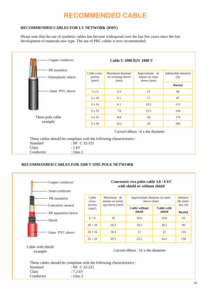
RECOMMENDED CABLES FOR LV NETWORK (950V)
Please note that the use of synthetic cables has become widespread over the last few years since the fast
development of materials new type. The use of PRC cables is now recommended.
RECOMMANDED CABLES FOR 3200 V ONE POLE NETWORK
Copper conductor
PR insulation
Elastoplastic sleeve
Outer PVC sleeve
These cables should be compliant with the following characteristics :
Standard : NF C 32-221
Class : 7.2 kV
Conductor : class 2
Cable U 1000 R2V 1000 V
Cable cross-
section
(mm²)
Maximum diameter
on isolating sleeve
(mm)
Admissible intensity
(A)
Approximate di-
ameter on outer
sleeve (mm)
Buried
3 x 6 4.3 15 66
3 x 10 5.1 17 87
3 x 16 6.1 19.5 113
3 x 25 7.8 23.5 144
3 x 35 8.8 26 174
3 x 50 10.2 29 206
Three pole cable
example
Curved ribbon : 6 x the diameter
Concentric two poles cable 3,6 / 6 kV
with shield or without shield
Cable
cross-
section
(mm²)
Maximum di-
ameter on isolat-
ing sleeve (mm)
Approximate diameter on outer
sleeve (mm)
Admissi-
ble inten-
sity (A)
Buried
Cable without
shield
Cable with
shield
6 + 6 16 18.6 19.6 63
10 + 10 16.5 19.2 20.2 90
16 + 16 18.3 21 22 115
25 + 25 20.5 23.2 24.2 150
Cable with shield
example Curved ribbon : 10 x the diameter
Copper conductor
PR insulation
Outer PVC sleeve
Shield
Concentric neutral
Semi-conductor
These cables should be compliant with the following characteristics :
Standard : NF C 32-321
Class : 1 kV
Conductor : class 2

17
RECOMMANDED CABLES FOR THREE PHASE NETWORK 5500 V - 6600 V
Copper conductor
Filling
Semi-conductor tape
Paper covered mattress
These cables should be compliant with the following characteristics :
Standard : NF C 32-220
Class : 7.2 kV
Conductor : class 2
Three pole non radial shielded cable 6 / 6 kV
Cable cross-
section
(mm²)
Acceptable intensity
(A)
Acceptable intensity
(A)
Outer diameter max.
(mm)
Buried Unburied
3 x 10 33 72 62
3 x 16 35 94 81
3 x 25 39.5 120 105
3 x 35 43 145 130
Three pole non radial
shielded example Curved ribbon : 9 x the outside diameter
Twisted three pole cable 3,6 / 6 kV
Outer diameter max. (mm) Acceptable intensity (A) Cable
cross-
section
(mm²) Sheath O-ring Buried Unburied
3 x 1 x 10 18 36 97 92
3 x 1 x 16 19.6 39.5 125 120
3 x 1 x 25 21.2 42.5 160 155
3 x 1 x 35 22.4 45 190 190
Twisted three pole
cable example
Copper conductor
PR insulation
Outside sheath
Copper shield
Semi conductor sleeve
Semi-conductor
Copper tape
Armour covered
Outside sheath
EPR insulation
Curved ribbon : 9 x the outside diameter
These cables should be compliant with the following characteristics :
Standard : NF C 32-220
Class : 7.2 kV
Conductor : class 2

18
This interlocking between the network feeder earthing isolating switch and the TER transformers allow safety
operation. For your installation, a special key for each feeder will be associated to locks with same number,
allowing access to all TER transformers of this feeder. We provide you from the number 10 to 52.
INTERLOCKING AND PIT
PRINCIPLE Thanks to an interlocking system, access to TER transformers and connection interfaces depend on the earthing and
short-circuiting of cabling supplied at origin. This is carried out by an interlocking key together with a Ronis or
Profalux key.
INTERLOCKING OF TER TRANSFORMERS TERMINALS It is possible to install directly on the TER transformer a mechanical interlocking system of MV and fuses
terminals. This interlocking system is used in the case of pit interlocking can not been used. The system is identical
to the pit interlocking system, with a locknut.
On request, it is possible to install an interlocking system with Ronis lock, RSP1 model.
Interlocking nuts example
Special keys
Nut
Interlocking TER TT 100 kVA Detail, interlocking by
special nut
Interlocking
TER MT 10 kVA

19
PITS INTERLOCKING
The intelocking key can activate a safety
lock N°7 to release the grid located inside
the inspection pit between access covering
and transformer.
Only specific parts corresponding to figures
5, 7 and 8 are listed on Augier price list.
MINIMAL DIMENSIONS OF CONCRETE PREFABRICATED PITS FOR TER
Type Power rating Concrete pits dimensions
Length Width Height
MM 1 to 10 kVA
1000
800
900 MT 1 to 10 kVA
MM 16 kVA
1300
750
1050 TT 5 and 10 kVA
MM 25 kVA
1450
800
1150 MT 16 and 25 kVA
TT 16 kVA
MM 32 kVA
1700
900
1300 MT 32 and 50 kVA
TT 25 and 32 kVA
TT 50 kVA 1700 900 1400
TT 80 to 160 kVA 1900 1000 1500
1. Fixation device
2. Washer
3. Stainless steel nut
4. Wire mesh
5. Nylon cap
6. HM 10 screw
7. Special nut
8. Cap
Special key
5
7
8

20
NETWORK MAINTENANCE TOOLS
The operation and maintenance on each TER transformers must be carried out whilst taking into account the advice
given by the NF C 17-200 standard and using the hereunder accessories.
The operation and maintenance procedure are described in the leaflet «operation and maintenance of 5500 V
network»
The manipulating
pole is used for all
the operations, it is
telescopic.
The sound signal voltage
detector is delivered in a
protection box , supplied
batteries.
SPECIFICS MAINTENANCE TOOLS :
Removal key :
Tools grounding :
The key for the one pole cap removal allows the
disconnection of the cap and the installation of the
earthing strap by means of the manipulating pole.
The earthing strap kit comprise a braid 1,5 m length, shunts and earthing clamps. The earthing strap allows the earthing and
short-circuiting of each one pole interfaces.
After unscrewing the cap of the one pole
terminal, the control of on load voltage
and also the earthing and short-circuiting
has to be carried out directly on the ac-
tive conductor.
Contact claw to connect
to the earth network
Braid
Tool grounding TER
terminals

21
SPARE PARTS
We provide you with references of parts that can be used for the maintenance of transformers.
BAG COVER BAG HOUSING BAG SEAL
HARDWARE AND JUMPER BAG HARDWARE AND SPACER BAG
Ref model 1 : 30 11236
Ref model 2*: 30 11516 Ref model 1 : 30 11237
Ref model 2*: 30 11517
Ref model 1 : 30 11238
Ref model 2*: 30 11518
Ref model 1 and 2 : 30 11239 Ref model 1 : 30 11240
Ref model 2*: 30 11519
PARTS OF THE TERMINAL
ACCESSORIES
SEALING CAP TER T SEALING CAP TER M
Ref : 30 10692 Ref : 30 11235
FUSE REMOVAL TOOLS
For 10x180 fuse
Ref : 10 23765
For 36x190 and 36x260 fuse
Ref : 10 24130
For 20x127, fuse
Ref : 30 10902
* Model 2 : from 12/2011
SEAL FOR FUSE TERMINAL
Ref : 10 24354
22
GLOSSARY
LV : Low voltage.
LVM : Maximum Low Voltage.
MV : Medium Voltage.
For continuous improvement, the manufacturer has the right to modify its models without notices.
Augier, for energy transportation, manufactures also step-down and step-up substations.
Augier let to your disposal the means and the material allowing the remote control and the
network supervision..
We also propose a product range allowing energy saving by means of voltage dimmers.

23
NOTES PERSONNELLES
24
AUGIER ® SA
BP 131 – 06513 CARROS Cedex
France
Tel. +33 (0)4 92 08 62 00 – Fax +33 (0)4 93 29 01 40
www.augier.com
AUGIER IS CERTIFIED ISO 9001 SINCE 1995
Wit
h c
onst
ant
impro
vem
ents
, th
e m
anu
fact
ure
r m
ay a
lter
info
rmat
ion w
itho
ut
pri
or
war
nin
g.