test house eport - gov.uk · > 4 instructions to ro's > national instruments...
TRANSCRIPT

Annex A
Test House report
The TEST HOUSEMAIBMountbatten HouseGrosvenor SquareSouthamptonS015 2JU
19 March 2010
Dear Sirs
PRELIMINARY REPORT IN RESPECT OF FRACTURED PORT AND STARBOARDHEAVY LIFT CRANE DECK PREVENTER PAD EYES
EX MV CORMORANT
THE TEST HOUSE JOB NUMBER: T00384
We take please in confirming our initial observations and calculations as follows.
1. VISUAL INSPECTION
1.1 Starboard Side Pieces
A clear fracture origin was apparent at each of the fractures in the steel plate(Figures 1 and 2). The two origins were in the ring retaining fillet welds and thefractures were consistent with a single generally low ductility overload event
The steel plate adjacent to the two fracture sites had undergone extensiveyielding, as was evidenced by the presence of widespread cracking in the paint(Figures 3 and 4).
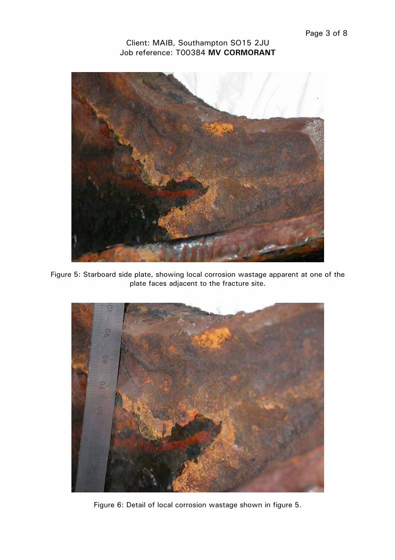
Evidence of earlier corrosion wastage was apparent on one of the plate facesadjacent to the fracture site (Figures 5 and 6). The wastage had reduced thelocal plate thickness by 3 to 4mm.
The two fillet welds retaining the ring had sheared through their weld throats,exposing some worm-hole porosity and local lack of fusion sites (Figures 7 and8). The weld fractures were apparent over a 490mm length of the ringscircumference and the average weld throat thickness was of the order of 8mm
1.2 Port Side Pieces
A clear fracture origin was apparent at one of the plate fracture sites (Figure 9),which was located in one of the ring retaining welds. The fracture at this plateside was consistent with a single generally low ductility overload event. Thefracture at the second site comprised largely shear (Figure 10), which hadprogressed from the plates inner flame profiled edge and towards the outer plate
TheTest House (Cambridge) Ltd. Granta Park, Great Abington. Cambridge CBI MI. Tel: 01223 899012 Fax: 01223 894255 E-mail: [email protected] w~.cthetesthouse.co.uk
Registered in England No. 2513984 RegisteredOffice: Granta Park. Great Abington. Cambridge TIVIThe Test House is a trading name of The Test House (Cambridge) Ltd, a wholly owned subsidiary of 1V.’l llZ~’

edge. This fracture, in contrast with the other three plate fractures, wasexclusively ductile in nature.
The steel plate adjacent to the two fracture sites had again undergone extensiveyielding, as was evidenced by the presence of widespread cracking in the paint(Figures 11 and 12).
Evidence of earlier corrosion wastage was apparent on one of the plate facesadjacent to the fracture site (Figures 13 and 14). The wastage had reduced thelocal plate thickness by 3 to 4mm.
The two fillet welds retaining the ring had sheared through their weld throats,exposing some worm-hole porosity (Figure 15). The weld fractures wereapparent over a 490mm length of the rings circumference and the average weldthroat thickness was of the order of 10mm.
2. ESTIMATE OF THE FRACTURE FORCE
To evaluate the fracture force an estimate was made of the fractured crosssectional area, and an assumed steel plate and weld metal strength was taken tobe equivalent to Lloyd’s Grades A to F (400 N/mm2 minimum tensile strength).The total fracture force was then estimated by assuming that three plateligaments had failed in direct tensile loading and that the fourth plate ligamentand the weld metal had all failed in shear (assumed shear strength taken to behalf the tensile strength).
Based on the above, a calculated estimate of the simultaneous single eventfracture force was 4,713KN. If it was assumed that the weld metal contributednothing to load sustaining, then a fracture force of 1,538 KN would have beenrequired to simultaneously fracture the four plate ligaments.
3. SUMMARY
3.1 Both the starboard and port preventer pad eyes appeared to have failed in asingle simultaneous event, and no evidence of prior fatigue cracking wasapparent in any of the pieces.
3.2 Estimates of the single event fracture force yielded a value of 4,713 KN, whichwas an order of magnitude greater than should have been applied during therigging operation.
3.3 Though evidence of some generally light corrosion wastage was apparent in thefractured plates. The apparent levels of corrosion were not considered to besignificant in the failure process.

3.4 Widespread evidence of welding defects, in the form of root worm-hole porosityand isolated sites of local lack of weld fusion, were apparent in both thestarboard and port ring retaining welds. The presence of weld defects, thoughindicative of poor workmanship, was not thought to be significant in the failureprocess.
4. CONCLUSIONS AND RECOMMENDATIONS
The two preventer pad eye plates had failed in a simultaneous single overloadevent, exposing no evidence of previous fatigue cracking. Though someevidence of light local corrosion wastage was apparent in both plates, thepresence of prior corrosion wastage was not considered significant in the failureprocess. Similarly, the widespread evidence of welder attributable weldingdefects was also not considered significant.
The failure was thought to have initiated in the starboard side plate, and two lowductility fractures were apparent in this item. The port side plate exhibited onelow ductility fast fracture and a more ductile shear fracture, which probablyrepresented the last plate ligament to fracture.
The preventer pads appeared to have failed in response to a fracture forte,which calculations suggest was an order of magnitude greater than the normalrigging load. Consequently, our opinion is the preventer pads had beendesigned with a suitable safety margin and that failure had resulted from anoperation defect rather than a latent design, materials or workmanship typedefect.
Based on our initial inspections, we do not currently believe that anything moresignificant is likely to ensue from completion of a more exhaustive laboratorywork scope.
Report prepared and authorised by
Director and Head of Laboratory
This letter report includes: Figure sheets 1 to 8 inclusive.

Page 1 of 8
Client: MAIB, Southampton SO15 2JU
Job reference: T00384 MV CORMORANT
Figure 1: Fracture in the starboard plate (fracture origin shown arrowed).
Figure 2: Second fracture in the starboard plate (fracture origin shown arrowed).

Page 2 of 8
Client: MAIB, Southampton SO15 2JU
Job reference: T00384 MV CORMORANT
Figure 3: Evidence of post yield point type straining (as evidenced by cracking in the
paint) for a considerable distance back from the starboard side fracture site.
Figure 4: As figure 3, but viewed from the opposite plate side.
Page 3 of 8
Client: MAIB, Southampton SO15 2JU
Job reference: T00384 MV CORMORANT
Figure 5: Starboard side plate, showing local corrosion wastage apparent at one of the
plate faces adjacent to the fracture site.
Figure 6: Detail of local corrosion wastage shown in figure 5.

Page 4 of 8
Client: MAIB, Southampton SO15 2JU
Job reference: T00384 MV CORMORANT
Figure 7: Sheared starboard ring retaining fillet weld, showing root worm-hole porosity.
Figure 8: Sheared starboard ring retaining fillet weld, showing local lack of fusion.

Page 5 of 8
Client: MAIB, Southampton SO15 2JU
Job reference: T00384 MV CORMORANT
Figure 9: Fracture in the port plate (fracture origin shown arrowed).
Figure 10: Shear fracture in the port plate (shearing direction shown arrowed).

Page 6 of 8
Client: MAIB, Southampton SO15 2JU
Job reference: T00384 MV CORMORANT
Figure 11: Evidence of post yield point type straining (as evidenced by cracking in the
paint) for a considerable distance back from the port side fracture site.
Figure 12: As figure 11, but viewed from the opposite plate side.

Page 7 of
Client: MAIB, Southampton SO15 2JU
Job reference: T00384 MV CORMORANT
Figure 13: Port side plate, showing local corrosion wastage apparent at one of the plate
faces adjacent to the fracture site.
Figure 14: Detail of local corrosion wastage shown in figure 13.

Page 8 of 8
Client: MAIB, Southampton SO15 2JU
Job reference: T00384 MV CORMORANT
Figure 15: Sheared port ring retaining fillet weld, showing root worm-hole porosity.

Annex B
Netherlands National Working Decree, Articles 7.20 and 7.29


Art. 7.20 Lifting and hoisting tools 1. Lifting and hoisting tools are chosen on the basis of the loads to be handled, the locations for slinging, the hook device and the weather conditions, taking into account the manner of slinging of the load and the lifting or hoisting gear to be used. 2. Lifting and hoisting tools, other than ropes or steel cables, have been provided with a well legible specification which mentions the workload. 3. Composed lifting and hoisting gear has been clearly marked to enable the user to know its features. 4. Except for the benefit of testing, lifting and hoisting gear is not loaded more heavily than the workload nor more heavily than a safe use permits. 5. Lifting and hoisting tools are stored such that it cannot be damaged or affected. 6. Lifting and hoisting tools are examined for its good condition by an expert natural person, legal person or institute at least once a year, while it is tested, if necessary. This person or institute disposes of the required equipment. 7. Evidences of the examinations and testings, as referred to in the sixth paragraph, are available at the workplace and are shown, upon request, to the supervisor. Art. 7.29 Lifting and hoisting gear and lifting and hoisting tools on board of ships 1. Contrary to Article 7.20, sixth and seventh paragraphs, the following provisions apply to lifting and hoisting gear as well as lifting and hoisting tools on board of ships, which are used for loading and unloading. 2. Lifing and hoisting gear including the corresponding fittings, components, points of attachment, anchorages and supports, and lifting and hoisting tools are effectively tested and examined for their good condition, before they are put into use for the first time. 3. Gear and tools as referred to in the second paragraph, are effectively tested and examined for their good condition after any important alteration or repair which may affect the safety. 4. Gear and tools as referred to in the second paragraph, are, depending on the actual load, regularly, but in any case at least once every five years, effectively tested and examined for their good condition,. 5. Lifting and hoisting gear and lifting and hoisting tools are, depending on the actual load, regularly, but in any case at least once a year, tested for their good condition. 6. Lifting and hoisting tools are, depending on the usage, regularly checked into their good condition. 7. Testings and examinations as referred to in the second through fourth paragraphs, are performed by Our Minister or a certificating institute. 8. Examinations and checks as referred to in the fifth and sixth paragraphs, are performed by an expert natural person, legal person or institute.

9. Certificates of the testings and examinations, as referred to in the second through fourth paragraphs, are issued by the certificating institute, as referred to in the seventh paragraph, according to a model established by Ministerial Regulation. 10. A register of lifting and hoisting gear and lifting and hoisting tools is kept on board of every ship according to a model established by Ministerial Regulation, in which the certificates as referred to in the ninth paragraph are incorporated. In the register are mentioned the operational load or operational loads of the lifting and hoisting gear, the workload of the lifting and hoisting tools as well as the times and the results of the testings and examinations as referred to in the second through fifth paragraphs. The times and the result of the checks as referred to in the sixth paragraph are mentioned, if a defect has been found at the relevant checks.

Annex C
Netherland’s guidance on the certification of lifting appliances and loose gear

> 4 INSTRUCTIONS to RO's > National Instruments (Instructions) : > National instructions : > 03 :Certification of lifting appliances and loose gear based on ILO 152
03 : - Certification of lifting appliances and loose gear based on ILO 152
Effective Date: 2006-08-01
No. 3 - Certification of lifting appliances and loose gear based on ILO 152
1. Lifting appliances and loose gear used for cargo handlingIn accordance with the relevant regulations of the Netherlands Working Conditions Decree (art 7.29) which arebased on the ILO 152 convention, the RO is recognized by the Secretary of State for Social Affairs andEmployment as certifying institution for lifting appliances and loose gear on board of seagoing ships.The RO is authorized to:
Perform the initial examination, testing and certification of cargo handling lifting appliances and loosegearPerform the 5-yearly testing and renewal of the certificateIssue the "Register of Lifting Appliances and Loose Gear" and enter the results of the initial and 5-yearlycertifications.
The NSI does not require any lifting appliances or loose gear to be "classed", but only that the relevant ILO 152regulations must be complied with. It is up to the shipowner to employ any of the recognized RO's to carry outthe above-mentioned examination, testing and certification services.
The annual thorough examinations required by ILO 152 may be carried out by a person from the ship's crew,shipyard, an independent contractor or RO, having the proper knowledge.
The conditions and reporting procedures that are part of the recognition by the Secretary of State for SocialAffairs and Employment remain unchanged.
2. Other lifting appliances and loose gear on board ships "Non-cargo handling" lifting appliances and loosegear on board ships shall be administered according to the relevant regulations of the Working ConditionsDecree (art 7.18, 7.18a and 7.20).It is up to the owner or master how to comply with the requirements. Any involvement of the RO is not underthe Agreement between the Administration and the RO.
As guidance the following items may be considered to be "Non-cargo handling" lifting appliances and loose gear(not limitative) :
I-beams above machinery etc.Lifting eyes or lugs.Overhead cranes in engine and pump rooms.Provision and hose-handling cranes and davits.Hand or power operated chain hoists (to be CE marked).Loose blocks, tackle and slings for non-cargo handling use.Gantry cranes for moving hatch covers
Source: Last Updated: 2009-06-30
Legislation Content Viewer - Transport and Water Management ... http://easyrules.ivw.nl/EasyRulesWeb/LegContentViewer.aspx?S...
1 of 1 24/08/2010 11:48

Annex D
MAIB safety flyer to the shipping industry


SAFETY FLYER TO THE SHIPPING INDUSTRYFailure of non-cargo handling lifting appliances
The dredger Sand Falcon was alongside at a jetty when the trolley from its gantry-type stores crane came off and fell 7.5m landing on the deck guardrails. The trolley weighed over 400kg and narrowly missed the 7 people who were working nearby on the main deck and ashore on the jetty. The crane was being prepared to load ship’s stores at the time and was not carrying any load.
The failure was due to a combination of design flaws, lack of maintenance and weaknesses in the inspection and testing methods used to assess the safety of the crane.
The floating sheerleg Cormorant was raising her 85t ‘A’ frame when two pad eye fittings holding wire supports detached from the deck causing the sheerleg to fall back onto the wheelhouse. Considerable damage resulted but there were no injuries.
The failure was due to the rigging being overloaded by the uncoordinated use of the hoisting and luffing winches. The raising of the sheerleg had not been identified as a key shipboard activity. There had been no risk assessment and no written operational procedures were provided. No alarms or interlocks were fitted to the hoisting system.
The pad eyes had not been identified as lifting equipment and had not been inspected or tested for 37 years. Although their condition was not considered to have contributed to the failure, weld fatigue was identified by non-destructive testing to corresponding pad eyes on board a similar vessel
The 77m general cargo vessel, Velox, was loading grain and the crew was tasked with painting the hull using the ship’s workboat. Instead of using the workboat’s hand-operated davit, a larger electrically-driven stores crane was used. An AB and cadet boarded the workboat and it was hoisted off the cradle. After some problems slewing the workboat outboard, the workboat was then lowered. When it had descended approximately 2m, the lifting wire parted and the boat, with its occupants, fell 8m into the water. Both the AB and the cadet suffered serious injuries.
The lifting wire was in an extremely poor condition and it was later found that the stores crane had not been maintained for some time. The stores crane was meant to have been decommissioned, but not everyone knew this and it had not been put out of use.
Overseas Camar was alongside loading a cargo of gas oil and a stores barge was secured on the outboard side. The stores crane had lifted the first load of hydraulic oil drums safely and a second load was being hoisted, when suddenly the load began to fall back onto the deck of the stores barge. The crewmen on the stores barge looked up and saw both the crane and its operator, who was in the control platform attached to the crane, falling. The crane struck the side of the ship, crushed a skip on the stores barge and fell into the sea. It was first thought that the operator had fallen into the sea too, but he landed on a lifeboat deck, some 5m below the crane pedestal. Although his injuries were severe, he was extremely fortunate not to have fallen further and been killed. Both crewmen on the stores barge were able to run clear.
The nuts and bolts used to hold the crane pedestal to the mounting ring were badly corroded, allowing the bolts to pull straight through the nuts. Neither the ship’s planned maintenance nor inspections by the classification society had detected how bad the corrosion had become.
These accidents are examples of the 29 similar cases that have been reported to MAIB since 2001 involving the failure of non-cargo handling cranes. The majority of these cases had the potential to cause fatal injuries and although there were no fatalities, a total of 11 people were injured.
Safety Lessons• Check that planned maintenance and inspections cover all parts of the equipment and
arrange proper access to reach components in awkward positions.
• If the manufacturer’s maintenance instructions are poor, or there are none, get expert assistance to make sure that the right maintenance is being done.
• Check that all non-cargo lifting appliances have been identified and recorded in accordance with national regulations. Some, like the rigging used to raise a sheerleg, might not be obvious.
• Make sure that those carrying out statutory inspections, load tests and thorough examinations are competent to do so. Employing contractors who meet a recognised industry standard should provide greater quality assurance.
• Follow the guidance on lifting equipment published by the Maritime and Coastguard Agency in Marine Guidance Notes 331 and 332, and in the Code of Safe Working Practices.
• Ensure that all key shipboard activities are identified, risk assessed and that the control measures identified, such as procedures, alarms and interlocks, are provided.
This flyer and relevant MAIB’s investigation reports are posted on our website:www.maib.gov.uk
For all other enquiries:Marine Accident Investigation BranchMountbatten HouseGrosvenor SquareSouthamptonSO15 2JUTel: 023 8039 5500Fax: 023 8023 2459Email: [email protected]
November 2010