test method: california non-methane organic gas test · pdf file ·...
TRANSCRIPT
As Amended: July 30, 2002Board Hearing: November 15, 2001
California Environmental Protection AgencyAIR RESOURCES BOARD
CALIFORNIA NON-METHANE ORGANIC GASTEST PROCEDURES
Adopted: July 12, 1991Amended: September 22, 1993Amended: June 24, 1996Amended: August 5, 1999Amended: July 30, 2002
Monitoring and Laboratory Division, Southern Laboratory BranchMobile Source Division
9528 Telstar AvenueEl Monte, California 91731
NOTE: Mention of any trade name or commercial product does not constitute endorsementor recommendation of this product by the Air Resources Board.

As Amended: July 30, 2002Board Hearing: November 15, 2001
TABLE OF CONTENTS
A. General Applicability and Requirements A-1
B. Determination of Non-Methane Hydrocarbon Mass Emissions by FlameIonization Detection B-1
C. Method 1001: Determination of Alcohols in Automotive Source Samples byGas Chromatography C-1
D. Method 1002: Determination of C2 to C5 Hydrocarbons in AutomotiveSource Samples by Gas Chromatography D-1
E. Method 1003: Determination of C6 to C12 Hydrocarbons in AutomotiveSource Samples by Gas Chromatography E-1
F. Method 1004: Determination of Aldehyde and Ketone Compounds inAutomotive Source Samples by High Performance Liquid Chromatography F-1
G. Determination of Non-Methane Organic Gas Mass Emissions G-1
APPENDICES
Appendix 1 - List of Light-End and Mid-Range Hydrocarbons 1-1
Appendix 2 - Definitions and Commonly Used Abbreviations 2-1
Appendix 3 - References 3-1
A-1As Amended: July 30, 2002Board Hearing: November 15, 2001
Part A
GENERAL APPLICABILITY AND REQUIREMENTS
1. These test procedures shall apply to all 1993 and subsequent model-year transitionallow-emission vehicles (TLEV), low-emission vehicles (LEV), ultra-low-emission vehicles(ULEV), and super-ultra-low-emission vehicles (SULEV) certifying to non-methane organicgas (NMOG) emission standards.
2. This document sets forth the analysis and calculation procedures that shall be performed todetermine NMOG mass emissions. The document consists of the following parts:
A. General Applicability and RequirementsB. Determination of Non-Methane Hydrocarbon Mass Emissions by Flame Ionization
DetectionC. Determination of Alcohols in Automotive Source Samples by Gas
Chromatography (Method No. 1001)D. Determination of C2 to C5 Hydrocarbons in Automotive Source Samples by Gas
Chromatography (Method No. 1002)E. Determination of C6 to C12 Hydrocarbons in Automotive Source Samples by Gas
Chromatography (Method No. 1003)F. Determination of Aldehyde and Ketone Compounds in Automotive Source
Samples by High Performance Liquid Chromatography (Method No. 1004).G. Determination of NMOG Mass Emissions
Appendix 1 List of Light-End and Mid-Range HydrocarbonsAppendix 2 Definitions and Commonly Used AbbreviationsAppendix 3 References
Alternative procedures may be used if shown to yield equivalent results and if approved in advanceby the Executive Officer of the Air Resources Board.
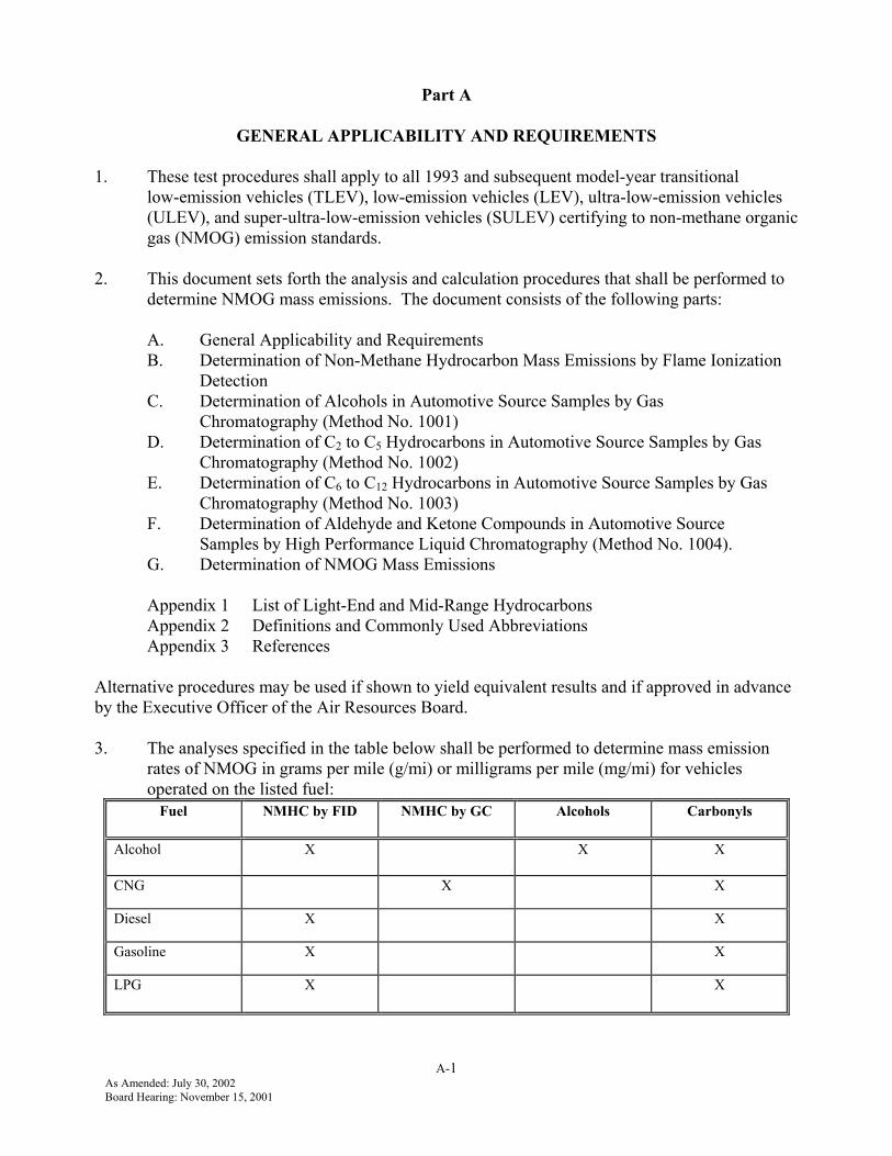
3. The analyses specified in the table below shall be performed to determine mass emissionrates of NMOG in grams per mile (g/mi) or milligrams per mile (mg/mi) for vehiclesoperated on the listed fuel:
Fuel NMHC by FID NMHC by GC Alcohols Carbonyls
Alcohol X X X
CNG X X
Diesel X X
Gasoline X X
LPG X X
A-2As Amended: July 30, 2002Board Hearing: November 15, 2001
The specified analyses shall be performed in accordance with the following parts of thisdocument:
NMHC by FID-- Part B. Determination of Non-Methane Hydrocarbon Mass Emissionsby Flame Ionization Detection
NMHC by GC-- Part D. Determination of C2 to C5 Hydrocarbons in AutomotiveSource Samples by Gas Chromatography (Method No. 1002);and
Part E. Determination of C6 to C12 Hydrocarbons in AutomotiveSource Samples by Gas Chromatography (Method No. 1003)
CARBONYLS-- Part F. Determination of Aldehyde and Ketone Compounds inAutomotive Source Samples by High Performance LiquidChromatography (Method No. 1004)
ALCOHOLS -- Part C. Determination of Alcohols in Automotive Source Samples byGas Chromatography (Method No. 1001)
4. For those manufacturers that choose to develop reactivity adjustment factors unique to aspecific engine family, exhaust NMOG emissions shall be fully speciated. NMHCemissions shall be analyzed in accordance with parts D and E (Method Nos. 1002 and1003). In addition, aldehydes and ketones, alcohols, and ethers shall be analyzed accordingto parts F, C, and E (Method Nos. 1004, 1001, and 1003). Analysis for alcohols shall berequired only for vehicles that are operated on fuels containing alcohols.
5. For natural gas-fueled vehicles, the methane concentration in the exhaust sample shall bemeasured with a methane analyzer. A GC combined with a FID is used for directmeasurement of methane concentrations. SAE Recommended Practice J1151 is a referenceon generally accepted GC principles and analytical techniques for this application. Adensity of 18.89 g/ft3 shall be used to determine the methane mass emissions. The methanemass emissions shall be multiplied by the appropriate methane reactivity adjustment factorand then added to the reactivity-adjusted NMOG emissions as specified in the “CaliforniaExhaust Emission Standards and Test Procedures for 1988-2000 Model Passenger Cars,Light-Duty Trucks, and Medium-Duty Vehicles” and in the “California Exhaust EmissionStandards and Test Procedures for 2001 and Subsequent Model Passenger Cars, Light-DutyTrucks, and Medium-Duty Vehicles.”
6. The mass of NMOG emissions shall be calculated in accordance with part G,“Determination of NMOG Mass Emissions”. The mass of NMOG emissions in g/mile ormg/mile shall be calculated by summing the mass of NMHC determined by the FID, themass of aldehydes and ketones, and the mass of alcohols.
B-1As Amended: July 30, 2002Board Hearing: November 15, 2001
PART B
DETERMINATION OF NON-METHANE HYDROCARBON MASS EMISSIONSBY FLAME IONIZATION DETECTION
1. INTRODUCTION
1.1 This procedure describes a method for determining NMHC exhaust mass emissions frommotor vehicles. Other applicable forms of instrumentation and analytical techniques whichprove to yield equivalent results to those specified in this procedure may be used subject tothe approval of the Executive Officer of the Air Resources Board.
1.2 All definitions and abbreviations are contained in Appendix 2 of these test procedures.
2. TOTAL HYDROCARBON MEASUREMENT
2.1 A FID is used to measure total hydrocarbon concentration in vehicle exhaust in accordancewith the Code of Federal Regulations [Ref.1]. SAE Recommended Practices J254 [Ref. 2]and J1094a [Ref. 3] are references on generally accepted gas analysis and constant volumesampling techniques. For Beckman 400 FIDs only, implementation of the recommendationsoutlined in SAE paper 770141[Ref. 4] shall be required. Other FID analyzer models shallbe checked and adjusted, if necessary, to minimize any non-uniformity of relative responseto different hydrocarbons.
3. METHANE MEASUREMENT
3.1 A GC combined with a FID constitute a methane analyzer and shall be used for directmeasurement of methane concentrations. The SAE Recommended Practice J1151[Ref. 5] isa reference on generally accepted GC principles and analytical techniques for this specificapplication.
4. TOTAL HC FID RESPONSE TO METHANE
4.1 The FID is calibrated to propane and therefore tends to over respond to the methane portionof the vehicle exhaust sample during hydrocarbon analysis. In order to calculate the NMHCconcentration, a methane response factor must be applied to the methane concentration (asmeasured by the methane analyzer) before it can be deducted from the total hydrocarbonconcentration. To determine the total hydrocarbon FID response to methane, knownmethane in air concentrations traceable to NIST shall be analyzed by the FID. Severalmethane concentrations shall be analyzed by the FID in the range of the exhaust sampleconcentration. The total hydrocarbon FID response to methane is calculated as follows:
rCH4 = FIDppm/SAMppm
B-2As Amended: July 30, 2002Board Hearing: November 15, 2001
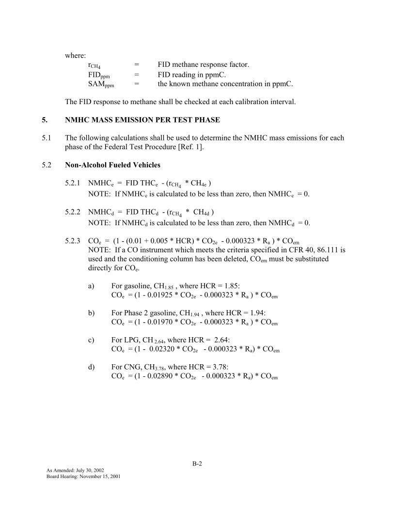
where:rCH4 = FID methane response factor.FIDppm = FID reading in ppmC.SAMppm = the known methane concentration in ppmC.
The FID response to methane shall be checked at each calibration interval.
5. NMHC MASS EMISSION PER TEST PHASE
5.1 The following calculations shall be used to determine the NMHC mass emissions for eachphase of the Federal Test Procedure [Ref. 1].
5.2 Non-Alcohol Fueled Vehicles
5.2.1 NMHCe = FID THCe - (rCH4 * CH4e )NOTE: If NMHCe is calculated to be less than zero, then NMHCe = 0.
5.2.2 NMHCd = FID THCd - (rCH4 * CH4d )NOTE: If NMHCd is calculated to be less than zero, then NMHCd = 0.
5.2.3 COe = (1 - (0.01 + 0.005 * HCR) * CO2e - 0.000323 * Ra ) * COemNOTE: If a CO instrument which meets the criteria specified in CFR 40, 86.111 isused and the conditioning column has been deleted, COem must be substituteddirectly for COe.
a) For gasoline, CH1.85 , where HCR = 1.85:COe = (1 - 0.01925 * CO2e - 0.000323 * Ra ) * COem
b) For Phase 2 gasoline, CH1.94 , where HCR = 1.94:COe = (1 - 0.01970 * CO2e - 0.000323 * Ra ) * COem
c) For LPG, CH 2.64, where HCR = 2.64:COe = (1 - 0.02320 * CO2e - 0.000323 * Ra) * COem
d) For CNG, CH3.78, where HCR = 3.78:COe = (1 - 0.02890 * CO2e - 0.000323 * Ra) * COem
B-3As Amended: July 30, 2002Board Hearing: November 15, 2001
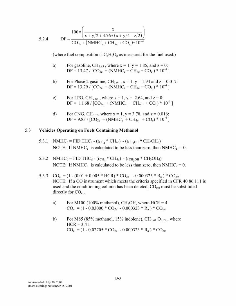
5.2.4( )
( ) 4e4ee2e 10COCHNMHCCO
2z4yx3.762yxx100
DF −∗+++
−+∗++
∗=
(where fuel composition is CxHyOz as measured for the fuel used.)
a) For gasoline, CH1.85 , where x = 1, y = 1.85, and z = 0:DF = 13.47 / [CO2e + (NMHCe + CH4e + COe ) * 10-4 ]
b) For Phase 2 gasoline, CH1.94 , x = 1, y = 1.94 and z = 0.017:DF = 13.29 / [CO2e + (NMHCe + CH4e + COe ) * 10-4 ]
c) For LPG, CH 2.64 , where x = 1, y = 2.64, and z = 0:DF = 11.68 / [CO2e + (NMHCe + CH4e + COe) * 10-4 ]
d) For CNG, CH3.78, where x = 1, y = 3.78, and z = 0.016:DF = 9.83 / [CO2e + (NMHCe + CH4e + COe) * 10-4 ]
5.3 Vehicles Operating on Fuels Containing Methanol
5.3.1 NMHCe = FID THCe - (rCH4 * CH4e) - (rCH3OH * CH3OHe) NOTE: If NMHCe is calculated to be less than zero, then NMHCe = 0.
5.3.2 NMHCd = FID THCd - (rCH4 * CH4d) - (rCH3OH * CH3OHd)NOTE: If NMHCd is calculated to be less than zero, then NMHCd = 0.
5.3.3 COe = (1 - (0.01 + 0.005 * HCR) * CO2e - 0.000323 * Ra ) * COemNOTE: If a CO instrument which meets the criteria specified in CFR 40 86.111 isused and the conditioning column has been deleted, COem must be substituteddirectly for COe .
a) For M100 (100% methanol), CH3OH, where HCR = 4:COe = (1 - 0.03000 * CO2e - 0.000323 * Ra ) * COem
b) For M85 (85% methanol, 15% indolene), CH3.41 O0.72 , whereHCR = 3.41:COe = (1 - 0.02705 * CO2e - 0.000323 * Ra ) * COem
B-4As Amended: July 30, 2002Board Hearing: November 15, 2001
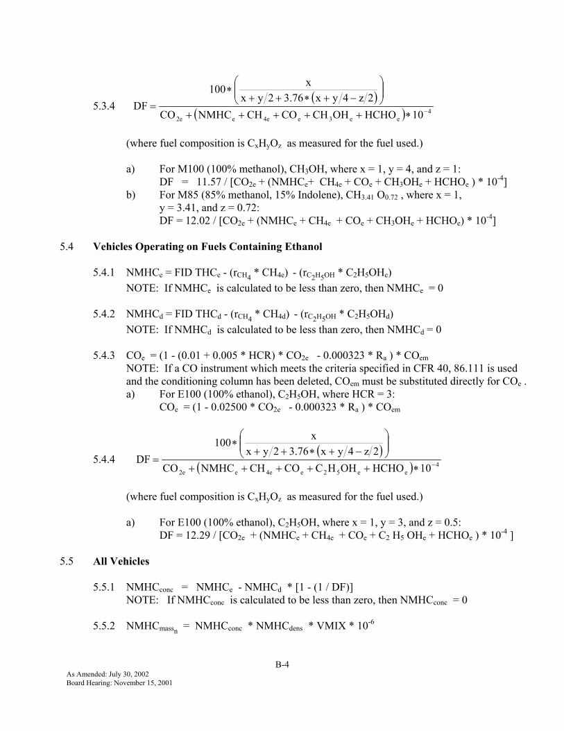
5.3.4 ( )
( ) 4ee3e4ee2e 10HCHOOHCHCOCHNMHCCO
2z4yx3.762yxx100
DF −∗+++++
−+∗++
∗=
(where fuel composition is CxHyOz as measured for the fuel used.)
a) For M100 (100% methanol), CH3OH, where x = 1, y = 4, and z = 1: DF = 11.57 / [CO2e + (NMHCe+ CH4e + COe + CH3OHe + HCHOe ) * 10-4]
b) For M85 (85% methanol, 15% Indolene), CH3.41 O0.72 , where x = 1,y = 3.41, and z = 0.72:DF = 12.02 / [CO2e + (NMHCe + CH4e + COe + CH3OHe + HCHOe) * 10-4]
5.4 Vehicles Operating on Fuels Containing Ethanol
5.4.1 NMHCe = FID THCe - (rCH4 * CH4e) - (rC2H5OH * C2H5OHe) NOTE: If NMHCe is calculated to be less than zero, then NMHCe = 0
5.4.2 NMHCd = FID THCd - (rCH4 * CH4d) - (rC2H5OH * C2H5OHd)NOTE: If NMHCd is calculated to be less than zero, then NMHCd = 0
5.4.3 COe = (1 - (0.01 + 0.005 * HCR) * CO2e - 0.000323 * Ra ) * COemNOTE: If a CO instrument which meets the criteria specified in CFR 40, 86.111 is usedand the conditioning column has been deleted, COem must be substituted directly for COe .a) For E100 (100% ethanol), C2H5OH, where HCR = 3:
COe = (1 - 0.02500 * CO2e - 0.000323 * Ra ) * COem
5.4.4 ( )
( ) 4ee52e4ee2e 10HCHOOHHCCOCHNMHCCO
2z4yx3.762yxx100
DF −∗+++++
−+∗++
∗=
(where fuel composition is CxHyOz as measured for the fuel used.)
a) For E100 (100% ethanol), C2H5OH, where x = 1, y = 3, and z = 0.5:DF = 12.29 / [CO2e + (NMHCe + CH4e + COe + C2 H5 OHe + HCHOe ) * 10-4 ]
5.5 All Vehicles
5.5.1 NMHCconc = NMHCe - NMHCd * [1 - (1 / DF)]NOTE: If NMHCconc is calculated to be less than zero, then NMHCconc = 0
5.5.2 NMHCmassn = NMHCconc * NMHCdens * VMIX * 10-6

B-5As Amended: July 30, 2002Board Hearing: November 15, 2001
6. TOTAL WEIGHTED NMHC MASS EMISSIONS
6.1 All Vehicles
6.1.1
++
∗+
++
∗=phase2phase3
mass2mass3
phase2phase1
mass2mass1wm DD
NMHCNMHC0.57
DDNMHCNMHC
0.43NMHC
7. SAMPLE CALCULATIONS
7.1 Given the following data for a gasoline vehicle, calculate the weighted NMHC mass emission.
TestPhase
FID THCe(ppmC)
FID THCd(ppmC)
CH4e(ppmC)
CH4d(ppmC)
COem(ppm)
CO2e(%)
VMIX(ft3)
Dphase n(mile)
Ra(%)
1 41.8 8.6 7.53 5.27 147.2 1.19 2846 3.583 38
2 13.0 8.4 5.68 5.10 20.8 0.80 4856 3.848 38
3 15.4 8.9 6.16 5.20 36.7 1.04 2839 3.586 38
For Phase 1:NMHCe = FID THCe - (rCH4 * CH4e )
= 41.8 ppmC - (1.04 * 7.53 ppmC)= 33.97 ppmC
NMHCd = FID THCd - (rCH4 * CH4d )= 8.6 ppmC - (1.04 * 5.27 ppmC)= 3.12 ppmC
COe = (1 - 0.01925 * CO2e - 0.000323 * Ra ) * COemNOTE: If a CO instrument which meets the criteria specified in CFR 40, 86.111 is usedand the conditioning column has been deleted, COem must be substituted directly for COe .
= (1 - 0.01925 * 1.19% - 0.000323 * 38%) * 147.18 ppm= 142.0 ppm
DF = 13.47 ÷ [CO2e + (NMHCe + CH4e + COe ) * 10-4]
DF = 13.47 1.19% + (33.97 ppmC + 7.53 ppmC + 142.0 ppmC) * 10-4
= 11.15
NMHCconc = NMHCe - NMHCd * [1 - (1 ÷ DF)]
B-6As Amended: July 30, 2002Board Hearing: November 15, 2001
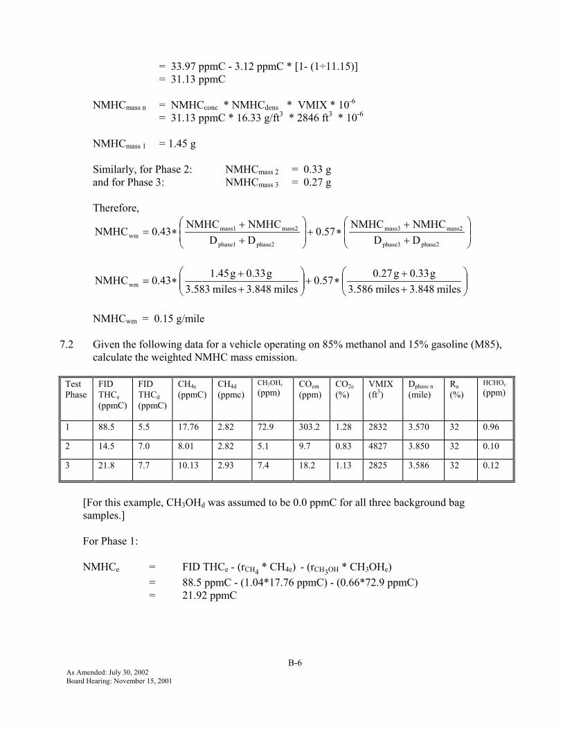
= 33.97 ppmC - 3.12 ppmC * [1- (1÷11.15)]= 31.13 ppmC
NMHCmass n = NMHCconc * NMHCdens * VMIX * 10-6
= 31.13 ppmC * 16.33 g/ft3 * 2846 ft3 * 10-6
NMHCmass 1 = 1.45 g
Similarly, for Phase 2: NMHCmass 2 = 0.33 gand for Phase 3: NMHCmass 3 = 0.27 g
Therefore,
++
∗+
++
∗=phase2phase3
mass2mass3
phase2phase1
mass2mass1wm DD
NMHCNMHC0.57
DDNMHCNMHC
0.43NMHC
++
∗+
++
∗=miles3.848miles3.586
g0.33g0.270.57miles3.848miles3.583
g0.33g1.450.43NMHCwm
NMHCwm = 0.15 g/mile
7.2 Given the following data for a vehicle operating on 85% methanol and 15% gasoline (M85),calculate the weighted NMHC mass emission.
TestPhase
FIDTHCe(ppmC)
FIDTHCd(ppmC)
CH4e(ppmC)
CH4d(ppmc)
CH3OHe
(ppm)COem(ppm)
CO2e(%)
VMIX(ft3)
Dphase n(mile)
Ra(%)
HCHOe
(ppm)
1 88.5 5.5 17.76 2.82 72.9 303.2 1.28 2832 3.570 32 0.96
2 14.5 7.0 8.01 2.82 5.1 9.7 0.83 4827 3.850 32 0.10
3 21.8 7.7 10.13 2.93 7.4 18.2 1.13 2825 3.586 32 0.12
[For this example, CH3OHd was assumed to be 0.0 ppmC for all three background bagsamples.]
For Phase 1:
NMHCe = FID THCe - (rCH4 * CH4e) - (rCH3OH * CH3OHe)= 88.5 ppmC - (1.04*17.76 ppmC) - (0.66*72.9 ppmC)= 21.92 ppmC

B-7As Amended: July 30, 2002Board Hearing: November 15, 2001
NMHCd = FID THCd - (rCH4 * CH4d) - (rCH3OH * CH3OHd)= 5.5 ppmC - (1.04*2.82 ppmC) - (0.66*0.0 ppmC)= 2.57 ppmC
COe = (1 - 0.02705 * CO2e - 0.000323 * Ra ) * COemNOTE: If a CO instrument which meets the criteria specified in CFR 40, 86.111 is usedand the conditioning column has been deleted, COem must be substituted directly for COe.
= (1 - 0.02705 * 1.28% - 0.000323 * 32%) * 303.2 ppm= 289.6 ppm
DF = 12.02 ÷ [CO2e + (NMHCe + CH4e + COe + CH3OHe + HCHOe) * 10-4]
( ) 410ppmC0.96ppmC72.9ppmC289.6ppmC17.76ppmC21.921.28%12.02
−∗+++++=
= 9.10
NMHCconc = NMHCe - NMHCd * [1 - (1 / DF)]= 21.92 ppmC - 2.57 ppmC * [1 - (1 / 9.10)]= 19.63 ppmC
NMHCmass n = NMHCconc * NMHCdens * VMIX * 10-6
NMHCmass 1 = 0.91 g
Similarly, Phase 2: NMHCmass 2 = 0.0 gand for Phase 3: NMHCmass 3 = 0.10 g
Therefore,
++
∗+
++
∗=phase2phase3
mass2mass3
phase2phase1
mass2mass1wm DD
NMHCNMHC0.57
DDNMHCNMHC
0.43NMHC
++
∗+
++
∗=miles3.850miles3.586
g0.00g0.100.57miles3.850miles3.570
g0.00g0.910.43NMHCwm
NMHCwm = 0.06 g/mile
C-1As Amended: July 30, 2002Board Hearing: November 15, 2001
Part C
DETERMINATION OF ALCOHOLSIN AUTOMOTIVE SOURCE SAMPLES
BY GAS CHROMATOGRAPHY
METHOD NO. 1001
1. INTRODUCTION
1.1 This document describes a method of sampling and analyzing automotive exhaustfor alcohols in the range of 1 to 1200 µg per 15 mL of solution. The “target”alcohols that shall be analyzed and reported by this method are methanol andethanol. These alcohols, when measured in concentrations above the LOD, shallbe reported.
1.2 This procedure is based on a method developed by the U. S. EnvironmentalProtection Agency, (U.S. EPA) [Ref 6] which involves flowing diluted engineexhaust through deionized or purified water contained in glass impingers andanalyzing this solution by gas chromatography .
1.3 All definitions and abbreviations are contained in Appendix 2 of these testprocedures.
2. METHOD SUMMARY
2.1 The samples are received by the laboratory in impingers. Compound separationand analysis are performed using a GC. The sample is injected into the GC bymeans of a liquid autosampler. Separation of the sample mixture into itscomponents is performed by a temperature-programmed capillary column. A FIDis used for alcohol detection and quantification.
2.2 The computerized GC data system identifies the alcohol associated with eachpeak. The alcohol concentrations are determined by integrating the peak areasand using response factors determined from external standards.
3. INTERFERENCES AND LIMITATIONS
3.1 An interferent is any component present in the sample with a retention timesimilar to that of any target alcohol described in this method. To reduceinterference error, proof of chemical identity may require periodic confirmationsusing an alternate method and/or instrumentation, e.g., GC/MS.

C-2As Amended: July 30, 2002Board Hearing: November 15, 2001
3.2 The concentration of the alcohols in the range of interest is stable for up to sixdays as long as the samples are sealed and refrigerated at a temperature below40oF.
4. INSTRUMENTATION AND APPARATUS
4.1 For each mode of the CVS test, two sampling impingers, each containing a knownamount of deionized or purified water (e.g. 15 mL for this procedure), are used tocontain the sample.
4.1.1 A temperature-programmable GC, equipped with a DB-Wax Megaborecolumn (30 m, 0.53 mm ID, 1.0 µ film thickness) and FID, is used. Othercolumns may be used, provided the alternate(s) can be demonstrated to beequivalent or better with respect to precision, accuracy and resolution ofall the target alcohols.
4.1.2 A liquid autosampler is required.
4.1.3 A PC-controlled data acquisition system for quantifying peak areas isrequired.
5. REAGENTS AND MATERIALS
5.1 Methanol shall have a purity of 99.9 percent, or be high performance liquidchromatography grade, EM Science or equivalent.
5.2 Ethanol shall be absolute, ACS reagent grade.
5.3 ASTM Type I purified or Type II deionized water shall be used.
5.4 Stock solutions are prepared gravimetrically or volumetrically by dilutingmethanol and ethanol with deionized or purified water, e.g., for this method atypical stock solution contains approximately 10 mg/mL of each target alcohol.Stock solutions must be replaced at least every six months.
5.4.1 A calibration standard within the expected concentration range of thesamples is prepared by successive dilutions of the stock solution withdeionized or purified water; 3 to 50 µg/mL is typical, depending on fueltype. Calibration standards must be replaced at least every week.
5.4.2 A control standard containing all target alcohols is prepared by successivedilutions of a stock solution different from that of Section 5.4.1. Thisstandard, at an approximate concentration of the samples, is used to monitorthe precision of the analysis of each target alcohol. Control standards mustbe replaced at least every week.

C-3As Amended: July 30, 2002Board Hearing: November 15, 2001
5.4.3 Standards used for linearity and LOD determinations (Section 8) are alsoprepared by successive dilutions of an appropriate level stock solution.
5.4.4 All standards should be refrigerated at a temperature below 40oF duringstorage.
5.5 Gas requirements.
5.5.1 Air shall be “Zero” grade (<1 ppmC total hydrocarbon contamination) orbetter.
5.5.2 Nitrogen shall have a minimum purity of 99.998 percent.
5.5.3 Helium shall have a minimum purity of 99.995 percent.
5.5.4 Hydrogen shall have a minimum purity of 99.995 percent.
6. PROCEDURE
6.1 Each of the graduated sampling impingers is filled with 15 mL of deionized orpurified water.
6.2 The impingers are placed in an ice bath during the sample collection.
6.3 After sampling, the solution contained in each impinger is transferred to a vialand sealed.
6.3.1 Samples shall be refrigerated at a temperature below 40oF if immediateanalysis is not feasible, or if reanalysis at a later date may be required.
6.4 One microliter aliquots of unmodified samples are injected via autosampler into aGC. Suggested standard operating conditions for the GC are:
Column: DB-Wax, 30 m, 0.53 mm ID, 1.0µ film thicknessCarrier gas flow: Helium at 5 mL/minMake-up gas flow: Nitrogen at 25 mL/minDetector: FID, hydrogen at 30 mL/min and air at 300 mL/minInjector: Packed column injector with Megabore adapter insert;
on-column injectionColumn temperature: 50oC (1 min), 50oC to 70oC (5oC/min), 70oC to 110oC
(15oC/min), 110oC (4 min)Data system: PC-based data acquisition system

C-4As Amended: July 30, 2002Board Hearing: November 15, 2001
6.5 Samples containing compounds having concentrations above the documentedrange of instrument linearity must be diluted and reanalyzed.
6.6 The peak integrations are corrected as necessary in the data system. Anymisplaced baseline segments are corrected in the reconstructed chromatogram.
6.7 The peak identifications provided by the computer are checked and corrected ifnecessary.
7. CALCULATIONS
7.1 The concentration of each target alcohol, in µg/mL, is determined by thefollowing calculation that compares the sample peak area with that of an externalstandard:
Concentration (µg/mL)sample = Peak Areasample x Response Factor
where the response factor (RF) is calculated during the calibration by:
( )
standard
mLµg standard
AreaPeakionConcentrat
RF =
7.2 This concentration is then used to calculate the total amount of alcohol in eachimpinger:
Mass (µg) = Concentration (µg/mL) x Impinger volume (mL)
7.3 An internal standard method may also be used.
8. QUALITY CONTROL
8.1 Blank Run - A deionized or purified water blank is run each analysis day. Alltarget alcohol concentrations from the blank analysis must be below the LODbefore the analysis may proceed.
8.1.1 If the blank shows a peak greater than the limit of detection (LOD) in theregion of interest, the source of the contamination must be investigatedand remedied.
8.2 Calibration Run - The calibration standard is analyzed each analysis day togenerate the response factor used to quantify the sample concentrations.
8.3 Control Standard Run - The quality control standard is analyzed at least once eachanalysis day. Measurements of all target alcohols in the control standard must fallwithin the control limits to ensure the validity of the sample analyses that day. To
C-5As Amended: July 30, 2002Board Hearing: November 15, 2001
meet this requirement, it may be necessary to inspect and repair the GC, and rerunthe calibration and/or control standards.
8.4 Control Charts - A quality control chart is maintained for each analyte in thecontrol standard. The control charts, used on a daily basis, establish that themethod is “in-control”. The following describes how to construct a typicalcontrol chart:
1. Obtain at least 20 daily control standard results;2. Calculate the control standard mean concentration and standard deviation
for the target analyte; and3. Create a control chart for the target analyte by placing the concentration
on the Y-axis and the date on the X-axis. Establish upper and lowerwarning limits at either two standard deviations (2s) or 5 percent,whichever is greater, above and below the average concentration.Establish upper and lower control limits at either three standard deviations(3s) or 5 percent, whichever is greater, above and below the averageconcentration.
4. A control standard measurement is considered to be out-of-control whenthe analyzed value exceeds the control limit or two successive controlstandard measurements of the same analyte exceed the warning limit.
5. If 20 control standard results are not yet available to create a control chart(e.g., the control standard was expended and replaced with a differentconcentration standard prior to obtaining 20 points with the new standard),measurements must be within 10% of the theoretical concentration.
The measured concentrations of all target analytes contained in the controlstandard must be within the control limits (“in-control”) for the sample results tobe considered acceptable.
8.5 Duplicates - A duplicate analysis of one sample is performed at least once peranalysis day. The relative percent difference (RPD) is calculated for eachduplicate run:
( ) 100tsmeasuremenoriginalandduplicateofAverage
tsmeasuremenoriginalandduplicatebetweenDifference%RPD ∗=
For each compound, the allowable RPD depends on the average concentrationlevel for the duplicate runs, as shown in the following table:
C-6As Amended: July 30, 2002Board Hearing: November 15, 2001
Average Measurement for Duplicate Runs Allowable RPD (%)1 to 10 times LOD 10010 to 20 “ “ 3020 to 50 “ “ 20Greater than 50 “ “ 15
If the results of the duplicate analyses do not meet these criteria for all targetalcohols, the sample may be reanalyzed. If reanalysis is not feasible or if thecriteria are still not met on reanalysis, all sample results for that analysis day areinvalid.
8.6 Linearity - A multipoint calibration to confirm instrument linearity is performedfor all target alcohols for new instruments, after making instrument modificationsthat can affect linearity, and at least once every year. The multipoint calibrationconsists of at least five concentration or mass loading levels, each above theLOD, distributed over the range of expected sample concentration. Eachconcentration level is measured at least twice. A linear regression analysis isperformed using concentration and area counts to determine the regressioncorrelation coefficient (r). The r must be greater than 0.995 to be consideredsufficiently linear for one point calibrations.
8.7 Limit of Detection - The LOD for the target alcohols must be determined for newinstruments, after making instrument modifications that can affect the LOD and atleast once every year. To make the calculations, it is necessary to perform amultipoint calibration consisting of at least four “low” concentration levels, eachabove the expected LOD, with at least five replicate determinations of the lowestconcentration standard. A linear regression is performed and the standarddeviation (in area counts) of the lowest concentration standard determined. Thestandard deviation is converted to concentration units using the slope of the linearregression:
s = sa ÷ m
where m is the slope of the linear regression, s is the standard deviation (inconcentration units) of the lowest concentration standard and sa is the standarddeviation (in area counts) of the lowest concentration standard.
The LOD must be calculated using the following equation [Ref. 12]:
stLOD ∗=
where s is the standard deviation (in concentration units) of at least five replicatedeterminations of the lowest concentration standard and t is the t-factor for 99percent confidence for a one-sided normal (Gaussian) distribution. The number of
C-7As Amended: July 30, 2002Board Hearing: November 15, 2001
degrees of freedom is equal to the number of replicates, minus one. An abbreviatedt–table is:
Degrees of Freedom t-value4 3.75 3.46 3.17 3.0
The lowest standard must be of a concentration of one to five times the estimatedLOD.
8.7.1 The maximum allowable LOD for each alcohol is 0.10 µg/mL. Thecalculated laboratory LOD must be equal to or lower than the maximumallowable LOD. All peaks identified as target compounds that are equal toor exceed the maximum allowable LOD must be reported. If thecalculated laboratory LOD is less than the maximum allowable LOD, thelaboratory may choose to set its reporting limit at the maximum allowableLOD, the calculated laboratory LOD, or any level in between.
8.7.2 For the purpose of calculating the total mass of all species, theconcentrations of the compounds below the LOD are considered to bezero.

D-1As Amended: July 30, 2002Board Hearing: November 15, 2001
Part D
DETERMINATION OF C2 TO C5 HYDROCARBONSIN AUTOMOTIVE SOURCE SAMPLES BY GAS CHROMATOGRAPHY
METHOD NO. 1002
1. INTRODUCTION
1.1 This document describes a gas chromatographic method of analyzing C2 to C5hydrocarbons (light-end hydrocarbons) in the ppbC range from automotive sourcesamples. This method does not include sample collection procedures [Ref. 8].The “target” hydrocarbons that shall be analyzed and reported by this method andMethod 1003 are listed in Appendix 1. All compounds on this list, whenmeasured in concentrations above the LOD, shall be measured and reported(“targeted”) by either Method 1002 or Method 1003. Each laboratory shoulddivide the list into light-end (Method 1002) and mid-range (Method 1003)hydrocarbons in the manner that best suits the laboratory instrumentation. Allcompounds on the list not targeted by Method 1002 must be targeted by Method1003.
1.2 All definitions and abbreviations are contained in Appendix 2 of these testprocedures.
2. METHOD SUMMARY
2.1 This is a method intended for routine analysis.
2.2 The samples are received by the laboratory in Tedlar bags, which are sub-sampledinto a GC for separation and analysis.
2.3 The gas chromatographic analysis is performed on an Alumina (Al203) PLOTcolumn temperature programmed from 0oC to 200oC. An FID is used fordetection and quantification.
2.4 The sample is injected into the GC by means of gas sampling valves. Separationof the sample hydrocarbon mixture into its components takes place in thechromatographic column. The chromatographic column and the correspondingoperating parameters described in this method normally provide completeresolution of most target compounds.
2.5 The computerized GC data acquisition system identifies the hydrocarbonsassociated with each peak. The hydrocarbon concentrations are determined byintegrating the peak areas and using response factors determined fromNIST-traceable standards.
D-2As Amended: July 30, 2002Board Hearing: November 15, 2001
3. INTERFERENCES AND LIMITATIONS
3.1 An interferent is any component present in the sample with a retention time verysimilar to that of any target hydrocarbon described in this method. To reduceinterference error, proof of chemical identity may require periodic confirmationsusing an alternate method and/or instrumentation, e.g., GC/MS, PID, differentcolumn, etc.
3.2 To maximize sample integrity, sample bags should not leak or be exposed tobright light or excessive heat. Sampling bags must be shielded from directsunlight to avoid photochemically induced reactions of any reactivehydrocarbons. The compound 1,3-butadiene, resulting mostly during cold-starttesting is unstable. Therefore all cold-start samples must be analyzed within 8hours; all other samples must be analyzed within 24 hours, although analysiswithin 8 hours is recommended.
4. INSTRUMENTS AND APPARATUS
4.1 Tedlar bags, 2 mil in thickness, nominally 5 to 10 liters in capacity and equippedwith quick-connect fittings, are used to contain the samples.
4.2 For manual sub-sampling into a GC, a ground glass syringe is used to transfergaseous samples from Tedlar bags to the GC sample inlet. For automatedsystems, a sample loop is used to transfer gaseous samples from the Tedlar bag tothe sample inlet of the GC. Sample aliquot size is chosen based on considerationsof instrument sensitivity and/or linearity.
4.3 A temperature-programmable GC equipped with a gas sampling valve system, aFID, and accessories is required.
4.4 An Alumina PLOT column (50 m x 0.32 mm) is used. A wax precolumn isrecommended to prevent water damage to the PLOT column. Other columns maybe used, provided the alternate(s) can be demonstrated to be equivalent or betterwith respect to precision, accuracy and resolution of all the target hydrocarbons.
4.5 A sample trap capable of being cryogenically cooled may be used.
4.6 Data acquisition software is used to integrate peak areas to determinehydrocarbon concentrations.
D-3As Amended: July 30, 2002Board Hearing: November 15, 2001
5. REAGENTS AND MATERIALS
5.1 Helium shall have a minimum purity of 99.995 percent. Higher purity heliummay be required to achieve the LOD required by Section 8.7.1.
5.2 Hydrogen shall have a minimum purity of 99.995 percent.
5.3 Air shall be “Zero” grade (<1 ppmC total hydrocarbon contamination) or better.
5.4 Nitrogen shall have a minimum purity of 99.998 percent.
5.5 Calibration Standard - The quantitative calibration standard for all targethydrocarbons shall be propane at a concentration level between 0.25 and1 ppm-mole and within the calculated linearity of the method. (See Section 8.6.)This propane standard must be a NIST-certified SRM or secondary NIST-traceable standard. A secondary standard is obtained by a comparison between aSRM and a candidate standard.
5.6 Control Standard - A quality control standard, containing at least ethene, propane,n-butane, and 2-methylpropene with concentrations between 0.2 and 3 ppmCbased on a propane standard, is used for the following purposes:
1. Daily update of control charts, and2. Daily determination of marker retention time windows.
5.7 A high concentration standard (higher than the calibration standard), containingthe target hydrocarbons listed in Section 5.6, is used for linearity determinations.The high concentration standard must have concentrations verified against aNIST-traceable propane standard. (See Section 5.5 for the definition ofNIST-traceable.) This verification can be performed at the laboratory performingthe analysis.
5.8 A low concentration standard (one to five times the estimated LOD), containingthe target hydrocarbons listed in Section 5.6, is used for LOD determinations.The low concentration standard must have concentrations verified against aNIST-traceable propane standard. (See Section 5.5 for the definition ofNIST-traceable.) This verification can be performed at the laboratory performingthe analysis.
5.8.1 In lieu of a low concentration standard, a higher concentration standardmay be diluted.
5.9 Liquid nitrogen may be required to cool the cryogenic sample trap and columnoven where applicable.
6. PROCEDURE

D-4As Amended: July 30, 2002Board Hearing: November 15, 2001
6.1 The gaseous sample is analyzed for the target hydrocarbons C2 through C5.
6.2 Suggested standard operating conditions for the gas chromatograph are:
Helium carrier gas velocity: 30 cm/sec at 2000CNitrogen make-up gas flow: sufficient such that the total flow of
helium plus nitrogen is 30 mL/minHydrogen gas flow: 30 mL/minAir flow: 300 mL/minSample valve temperature: 1500C (PLOT column)Column temperature: 00C (hold 7 min),
100C/min to 2000C (hold 15 min)Detector temperature: 2500CInjector temperature: 1500C
6.3 For automated systems, connect the samples to the GC and begin the analyticalprocess.
6.4 Introduce the sample into the carrier gas stream through the injection valve.
6.5 Each separated component exits from the column into the FID where a response isgenerated.
6.6 Concentrations of hydrocarbons are calculated using data acquisition/ processingsoftware that uses calibration data from the NIST-traceable propane calibrationstandard.
6.7 For compounds having concentrations above the documented range of instrumentlinearity, a smaller aliquot must be taken (for manual systems, a smaller syringeor smaller loop; for automated systems, a smaller loop) or the sample must bediluted.
6.8 The peak integrations are corrected as necessary in the data system. Anymisplaced baseline segments are corrected in the reconstructed chromatogram.
6.9 The peak identifications provided by the computer are checked and corrected ifnecessary.
6.10 Target compounds that coelute are reported as the major component, as determinedby the analysis of several samples by GC/MS or other methods. An exception tothis is m- and p-xylene, where GC/MS data and fuel profiles are used to determinethe relative contribution of each component to the peak. This method was used todetermine the m- and p-xylene MIR value given in Appendix 1.

D-5As Amended: July 30, 2002Board Hearing: November 15, 2001
6.11 The Alumina PLOT column is programmed to 200oC to assure all compounds areeluted before the next run.
7. CALCULATIONS
7.1 The target hydrocarbon concentrations, in ppbC, are calculated by the data systemusing propane as an external standard.
Concentrationsample (ppbC) = Peak Areasample x Response Factor
where the response factor (RF) is calculated during daily calibration by:
RF = Concentration of NIST-traceable propane standard, ppbC Area of propane peak
8. QUALITY CONTROL
8.1 Blank Run - A blank (pure nitrogen or helium) is run each analysis day. Alltarget hydrocarbon concentrations from the blank analysis must be below theLOD before the analysis may proceed. As an alternative to a daily blank run, adaily partial blank check in tandem with a weekly blank run may be used. Apartial blank check is defined as a check of the calibration standard run forcontamination over all but the propane region of the chromatograph. Thecalibration standard must consist of only propane and make-up gas, with theconcentration of all organic compounds except methane and propane below 2percent of the propane standard concentration. The weekly blank run will providea check on contamination in the propane region of the chromatograph.
8.1.1 If the blank shows a peak greater than the limit of detection (LOD) in theregion of interest, the source of contamination must be investigated andremedied.
8.2 Calibration Run - The calibration standard is analyzed each analysis day togenerate the response factor used to quantify the sample concentrations.
8.3 Control Standard Run - The quality control standard is analyzed at least once eachanalysis day. Measurements of all compounds specified in Section 5.6 must fallwithin the control limits to ensure the validity of the sample analyses that day. Tomeet this requirement, it may be necessary to inspect and repair the GC, and rerunthe calibration and/or control standards.
8.4 Control Charts - A quality control chart is maintained for each component of thecontrol standard listed in Section 5.6. The control charts, used on a daily basis,establish that the method is “in- control.” The following describes how toconstruct a typical control chart:
D-6As Amended: July 30, 2002Board Hearing: November 15, 2001
1. Obtain at least 20 daily control standard results;2. Calculate the control standard mean concentration and standard deviation
for the target hydrocarbon; and3. Create a control chart for the target hydrocarbon by placing the
concentration on the Y-axis and the date on the X-axis. Establish upperand lower warning limits at either two standard deviations (2s) or 5percent, whichever is greater, above and below the average concentration.Establish upper and lower control limits at either three standard deviations(3s) or 5 percent, whichever is greater, above and below the averageconcentration.
4. A control standard measurement is considered to be out-of-control whenthe analyzed value exceeds the control limit or two successive controlstandard measurements of the same analyte exceed the warning limit.
5. If 20 control standard measurements are not yet available to create acontrol chart (e.g., the control standard was expended and replaced priorto obtaining 20 points with the new standard), measurements must bewithin 10% of the certified concentration. If the control standard is not aNIST standard, the cylinder should be certified by the laboratory against aNIST standard.
The measured concentrations of all target hydrocarbons contained in the controlstandard must be within the control limits (in-control) for the sample results to beconsidered acceptable.
8.5 Duplicates - A duplicate analysis of one sample is performed at least once peranalysis day. The relative percent difference (RPD) is calculated for eachduplicate run:
RPD (%) = |Difference between duplicate and original measurements| x 100Average of duplicate and original measurements
For each compound specified in Section 5.6, the allowable RPD depends on theaverage concentration level for the duplicate runs, as shown in the followingtable:
Average Measurement for the Duplicate Runs Allowable RPD (%)1 to 10 times LOD 10010 to 20 “ “ 3020 to 50 “ “ 20Greater than 50 “ “ 15
If the results of the duplicate analyses do not meet these criteria for allcompounds specified in Section 5.6, the sample may be reanalyzed. If reanalysisis not feasible or if the criteria are still not met on reanalysis, all sample results forthat analysis day are invalid.
D-7As Amended: July 30, 2002Board Hearing: November 15, 2001
8.6 Linearity - A multipoint calibration to confirm instrument linearity is performedfor the target hydrocarbons in the control standard for new instruments, aftermaking instrument modifications that can affect linearity, and at least once everyyear unless a daily check of the instrument response indicates that the linearityhas not changed. To monitor the instrument response, a quality control chart isconstructed, as specified in Section 8.4, except using calibration standard areacounts rather than control standard concentrations. When the standard areacounts are out-of-control, corrective action(s) must be taken before analysis mayproceed. The multipoint calibration consists of at least five concentration or massloading levels (using smaller or larger volume sample sizes of existing standardsis acceptable), each above the LOD, distributed over the range of expected sampleconcentration. Each concentration level is measured at least twice. A linearregression analysis is performed using concentration and average area counts todetermine the regression correlation coefficient (r). The r must be greater than0.995 to be considered sufficiently linear for one-point calibrations.
8.7 Limit of Detection – The LOD for the target hydrocarbons in the control standardmust be determined must be determined for new instruments and after makinginstrument modifications that can affect linearity and/or sensitivity and at leastonce every year unless a daily check of the instrument response indicates that theLOD has not changed. To monitor the instrument response, a quality controlchart is constructed, as specified in Section 8.4, except using calibration standardarea counts rather than control standard concentrations. When the calibrationstandard area counts are out-of-control, investigation and/or corrective action(s)must be taken. To make the calculations, it is necessary to perform a multipointcalibration consisting of at least four “low” concentration levels, each above theLOD, with at least five replicate determinations of the lowest concentrationstandard. A linear regression is performed and the standard deviation isconverted to concentration units using the slope of the linear regression:
s = sa ÷ m
where m is the slope of the linear regression, s is the standard deviation (inconcentration units) of the lowest concentration standard and sa is the standarddeviation (in area counts) of the lowest concentration standard.
The LOD must be calculated using the following equation [Ref. 12]:
stLOD ∗=
where s is the standard deviation (in concentration units) of at least five replicatedeterminations of the lowest concentration standard and t is the t-factor for 99percent confidence for a one-sided normal (Gaussian) distribution. The number ofdegrees of freedom is equal to the number of replicates, minus one. An abbreviatedt-table is:

D-8As Amended: July 30, 2002Board Hearing: November 15, 2001
Degrees of Freedom t-value4 3.75 3.46 3.17 3.0
The lowest standard must be of a concentration of one to five times the estimatedLOD.
8.7.1 The maximum allowable LOD for each compound is 5 ppbC. Thecalculated laboratory LOD must be equal to or lower than the maximumallowable LOD. All peaks identified as target compounds that are equal toor exceed the maximum allowable LOD must be reported. If thecalculated laboratory LOD is less than the maximum allowable LOD, thelaboratory may choose to set its reporting limit at the maximum allowableLOD, the calculated laboratory LOD, or any level in between.
8.7.2 For the purpose of calculating the total mass of all species, theconcentrations of all compounds below the LOD are considered to bezero.
8.8 Method No. 1002/Method No. 1003 Crossover Check - For each sample, acompound shall be measured by both Method No. 1002 and Method No. 1003.The crossover compound shall be a compound that can reasonably be expected tobe found and measured by both methods in the laboratory performing theanalysis. The results obtained by the two methods should be compared and anacceptance criteria set for the relative percent difference.
E-1As Amended: July 30, 2002Board Hearing: November 15, 2001
Part E
DETERMINATION OF C6 TO C12 HYDROCARBONSIN AUTOMOTIVE SOURCE SAMPLES BY GAS CHROMATOGRAPHY
METHOD NO. 1003
1. INTRODUCTION
1.1 This document describes a gas chromatographic method of analyzing C6 to C12hydrocarbons (mid-range hydrocarbons) in the ppbC range from automotivesource samples. This method does not include sample collection procedures [Ref.7]. The target hydrocarbons that shall be analyzed and reported by this methodand Method 1002 are listed in Appendix 1. All compounds on this list, whenmeasured in concentrations above the LOD, shall be measured and reported(“targeted”) by either Method 1002 or Method 1003. Each laboratory shoulddivide the list into light-end (Method 1002) and mid-range (Method 1003)hydrocarbons in the manner that best suits the laboratory instrumentation. Allcompounds on the list not targeted by Method 1003 must be targeted by Method1002.
1.2 All definitions and abbreviations are contained in Appendix 2 of these testprocedures.
2. METHOD SUMMARY
2.1 This is a method intended for routine analysis.
2.2 The samples are received by the laboratory in Tedlar bags, which are sub-sampledinto a GC for separation and analysis.
2.3 The gas chromatographic analysis is performed through a temperature-programmed capillary column. A FID is used for detection.
2.4 The sample is injected into the GC by means of gas sampling valves. Separationof the sample hydrocarbon mixture into its components takes place in thechromatographic column. The chromatographic column and the correspondingoperating parameters described in this method normally provide completeresolution of most target hydrocarbons.
2.5 The computerized GC data acquisition system identifies the hydrocarbonsassociated with each peak. The hydrocarbon concentrations are determined byintegrating the peak areas and using a response factor determined fromNIST-traceable standards.

E-2As Amended: July 30, 2002Board Hearing: November 15, 2001
3. INTERFERENCES AND LIMITATIONS
3.1 An interferent is any component present in the sample with a retention timesimilar to that of any target hydrocarbon described in this method. To reduceinterference error, proof of chemical identity may require periodic confirmationsusing an alternate method and/or instrumentation, e.g., GC/MS, PID, differentcolumn, etc.
3.2 The concentration of hydrocarbons in the range of interest is stable for at least 24hours in the Tedlar sampling bags, provided the sample bags do not leak and arenot exposed to bright light or excessive heat. Sampling bags must be shieldedfrom direct sunlight to avoid photochemically induced reactions of any reactivehydrocarbons. Samples must be analyzed within 24 hours.
4. INSTRUMENTATION AND APPARATUS
4.1 Tedlar bags, 2 mil in thickness, nominally 5 to 10 liters in capacity and equippedwith quick-connect fittings, are used to contain the samples.
4.2 For manual sub-sampling into a GC, a ground glass syringe is used to transfergaseous samples from Tedlar bags to the GC sample inlet. For automatedsystems, a sample loop is used to transfer gaseous samples from the Tedlar bag tothe sample inlet of the GC. Sample aliquot size is chosen based on considerationsof instrument sensitivity and/or linearity.
4.3 The GC is equipped with a FID, and a gas sampling valve system.
4.4 A non-polar capillary column [e.g., J&W DB-1, 60 m x 0.32 mm ID, filmthickness 1.0 µ] is used. Other columns may be used, provided the alternate(s)can be demonstrated to be equivalent or better with respect to precision, accuracyand resolution of all the target hydrocarbons.
4.5 A sample trap capable of being cryogenically cooled may be used.
4.6 A computer-controlled data acquisition system is required for quantifying peakareas.
5. REAGENTS AND MATERIALS
5.1 Helium shall have a minimum purity of 99.995 percent. Higher purity heliummay be required to achieve the LOD required by Section 8.7.1.
5.2 Hydrogen shall have a minimum purity of 99.995 percent.
5.3 Air shall be “Zero” grade (<1 ppmC total hydrocarbon contamination) or better.
E-3As Amended: July 30, 2002Board Hearing: November 15, 2001
5.4 Nitrogen shall have a minimum purity of 99.998 percent.
5.5 Calibration Standard - The quantitative calibration standard for all targethydrocarbons shall be propane at a concentration level between 0.25 and 1ppm-mole and within the calculated linearity of the method. (See Section 8.6.)This propane standard must be a NIST-certified SRM or secondary NIST-traceable standard. A secondary standard is obtained by a comparison between aSRM and a candidate standard.
5.6 Control Standard - A quality control standard, containing at least n-hexane,n-octane, n-decane, benzene, toluene, and m- or p-xylene with concentrationsbetween 0.2 and 1 ppmC based on a propane standard, is used for the followingpurposes:
1. Daily update of control charts, and2. Daily determination of marker retention time windows.
5.7 A high concentration standard (higher than the calibration standard), containingthe target hydrocarbons listed in Section 5.6, is used for linearity determinations.The high concentration standard must have concentrations verified against aNIST-traceable propane standard. (See Section 5.5 for the definition ofNIST-traceable.) This verification can be performed at the laboratory performingthe analysis.
5.8 A low concentration standard (one to five times the estimated LOD), containingthe target hydrocarbons listed in Section 5.6, is used for LOD determinations.The low concentration standard must have concentrations verified against aNIST-traceable propane standard. (See Section 5.5 for the definition ofNIST-traceable.) This verification can be performed at the laboratory performingthe analysis.
5.8.1 In lieu of a low concentration standard, a higher concentration standardmay be diluted.
5.9 Liquid nitrogen may be required to cool the cryogenic trap and column ovenwhere applicable.

E-4As Amended: July 30, 2002Board Hearing: November 15, 2001
6. PROCEDURE
6.1 Typical operating conditions.
6.1.1 Suggested operating conditions for the manual GC are:Helium carrier gas velocity: 30 cm/sec at 200oCNitrogen make-up gas flow: sufficient such that the total flow of
helium plus nitrogen is 30 mL/minHydrogen gas flow (for FID): 30 mL/min“Zero” air gas flow (for FID): 300 mL/minAutozero FID at: 0.0 minRange 11, Attenuation 8 (or another suitable value)Sample valve temperature: 150oCInjector temperature: 150oCColumn entrance port temperature: 95oCDetector temperature: 250oCColumn temperature: Initial temperature 0oC;
10oC/min to 200oC
6.1.2 Suggested operating conditions for the automated GC are:Helium carrier gas velocity: 30 cm/sec at 200oCNitrogen make-up gas flow: sufficient such that the total flow of
helium plus nitrogen is 30 mL/minHydrogen gas flow (for FID): 30 mL/min“Zero” air gas flow (for FID): 300 mL/minRange 12, attenuation 8 (or another suitable value)Sample valve temperature: 150oCDetector temperature: 300oCInjector temperature: 150oCColumn temperature: Initial temperature -50oC (5 min),
5oC/min to 50oC,10oC/min to 200oC
6.2 Data Reduction
6.2.1 The results are calculated from the FID responses.
6.2.2 The results are examined to see that the peaks are correctly integrated.
6.2.3 After running a particularly “dirty” sample, the analyst should run a blankbefore proceeding to the next sample as there may be sample carryover, orflush the sampling system with air.
6.2.4 The peak identifications provided by the computer are reviewed and, ifnecessary, corrected using the following procedure and criteria:
E-5As Amended: July 30, 2002Board Hearing: November 15, 2001
1. The relative retention indices from GC/MS analyses are used tohelp confirm peak identifications.
2. The primary peak identification is done by the computer using therelative retention times based on reference calibration runs.
3. Confirm that the relative peak heights of the sample run(“fingerprint”) match the typical fingerprint seen in past sampleruns.
4. Compare the relative retention times of the sample peaks withthose of reference runs.
5. Any peak with a reasonable doubt is labeled 'Unidentified'.
6.2.5 For compounds having concentrations above the documented range ofinstrument linearity, a smaller aliquot must be taken (for manual systems,a smaller syringe or smaller loop; for automated systems, a smaller loop)or the sample must be diluted.
6.2.6 The concentrations of the hydrocarbons are calculated using dataacquisition/ processing software which uses calibration data from aNIST-traceable propane calibration standard.
6.2.7 Target compounds that coelute are reported as the major component, asdetermined by the analysis of several samples by GC/MS or othermethods. An exception to this is m- and p-xylene, where GC/MS data andfuel profiles are used to determine the relative contribution of eachcomponent to the peak. This method was used to determine the m- and p-xylene MIR value given in Appendix 1.
7. CALCULATIONS
7.1 The target hydrocarbon concentrations, in ppbC, are calculated by the data systemusing propane as an external standard.
Concentrationsample (ppbC) = Peak Areasample ∗ Response Factor
where the Response Factor (RF) is calculated during daily calibration by:
peakpropaneofAreappbCstandard,propanetraceableNISTofionConcentratRF −
=

E-6As Amended: July 30, 2002Board Hearing: November 15, 2001
8. QUALITY CONTROL
8.1 Blank Run - A blank (pure nitrogen or helium) is run each analysis day. Alltarget hydrocarbon concentrations from the blank analysis must be below theLOD before the analysis may proceed. As an alternative to a daily blank run, adaily partial blank check in tandem with a weekly blank run may be used. Apartial blank check is defined as a check of the calibration standard run forcontamination over all but the propane region of the chromatograph. Thecalibration standard must consist of only propane and make-up gas, with theconcentration of all organic compounds except methane and propane below 2percent of the propane standard concentration. The weekly blank run will providea check on contamination in the propane region of the chromatograph.
8.1.1 If the blank shows a peak greater than the limit of detection (LOD) in theregion of interest, the source of the contamination must be investigatedand remedied.
8.2 Calibration Run - The calibration standard is analyzed each analysis day togenerate the response factor used to quantify the sample concentrations.
8.3 Control Standard Run - The quality control standard is analyzed at least once eachanalysis day. Measurements of all compounds specified in Section 5.6 must fallwithin the control limits to ensure the validity of the sample analyses that day. Tomeet this requirement, it may be necessary to inspect and repair the GC, and rerunthe calibration and/or control standards.
8.4 Control Charts - A quality control chart is maintained for each component of thecontrol standard listed in Section 5.6. The control charts, used on a daily basis,establish that the method is “in-control”. The following describes how toconstruct a typical control chart:
1. Obtain at least 20 daily control standard results,2. Calculate the control standard mean concentration and standard deviation
for the target hydrocarbon, and3. Create a control chart for the target hydrocarbon by placing the
concentration on the Y-axis and the date on the X-axis. Establish upperand lower warning limits at either two standard deviations (2s) or 5percent, whichever is greater, above and below the average concentration.Establish upper and lower control limits at either three standard deviations(3s) or 5 percent, whichever is greater, above and below the averageconcentration.
4. A control standard measurement is considered to be out-of-control whenthe analyzed value exceeds the control limit or two successive controlstandard measurements of the same analyte exceed the warning limit.
5. If 20 control standard measurements are not yet available to create acontrol chart (e.g., the control standard was expended and replaced prior

E-7As Amended: July 30, 2002Board Hearing: November 15, 2001
to obtaining 20 points with the new standard), measurements must bewithin 10% of the certified concentration. If the control standard is not aNIST standard, the cylinder should be certified by the laboratory against aNIST standard.
The measured concentrations of all target hydrocarbons contained in the controlstandard must be within the control limits (in-control) for the sample results to beconsidered acceptable.
8.5 Duplicates - A duplicate analysis of one sample is performed at least once peranalysis day. The relative percent difference (RPD) is calculated for eachduplicate run:
( ) 100tsmeasuremenoriginalandduplicateofAverage
|tsmeasuremenoriginalandduplicatebetweenDifference|%RPD ∗=
For each compound specified in Section 5.6, the allowable RPD depends on theaverage concentration level for the duplicate runs, as shown in the followingtable:
Average Measurement for Duplicate Runs Allowable RPD (%)1 to 10 times LOD 10010 to 20 “ “ 3020 to 50 “ “ 20Greater than 50 “ “ 15
If the results of the duplicate analyses do not meet these criteria for allcompounds specified in Section 5.6, the sample may be reanalyzed. If reanalysisis not feasible or if the criteria are still not met on reanalysis, all sample results forthat analysis day are invalid.
8.6 Linearity - A multipoint calibration to confirm instrument linearity is performedfor all target hydrocarbons in the control standard for new instruments, aftermaking instrument modifications that can affect linearity, and at least once everyyear unless a daily check of the instrument response indicates that the linearityhas not changed. To monitor the instrument response, a quality control chart isconstructed, as specified in Section 8.4, except using calibration standard areacounts rather than control standard concentrations. When the standard areacounts are out-of-control, corrective action(s) must be taken before analysis mayproceed. The multipoint calibration consists of at least five concentration or massloading levels (using smaller or larger volume sample sizes of existing standardsis acceptable), each above the LOD, distributed over the range of expected sampleconcentration. Each concentration level is measured at least twice. A linearregression analysis is performed using concentration and average area counts to
E-8As Amended: July 30, 2002Board Hearing: November 15, 2001
determine the regression correlation coefficient (r). The r must be greater than0.995 to be considered sufficiently linear for one point calibrations.
8.7 Limit of Detection - The LOD for the target hydrocarbons in the control standardmust be determined for new instruments and after making instrumentmodifications that can affect linearity and/or sensitivity and at least once everyyear unless a daily check of the instrument response indicates that the LOD hasnot changed. To monitor the instrument response, a quality control chart isconstructed, as specified in Section 8.4, except using calibration standard areacounts rather than control standard concentrations. When the calibration standardarea counts are out-of-control, investigation and/or corrective action(s) must betaken. To make the calculations, it is necessary to perform a multipointcalibration consisting of at least four “low” concentration levels, each above theLOD, with at least five replicate determinations of the lowest concentrationstandard. A linear regression is performed and the standard deviation (in areacounts) of the lowest concentration standard determined. The standard deviationis converted to concentration units using the slope of the linear regression:
s = sa ÷ m
where m is the slope of the linear regression, s is the standard deviation (inconcentration units) of the lowest concentration standard and sa is the standarddeviation (in area counts) of the lowest concentration standard.
The LOD must be calculated using the following equation [Ref. 12]:
stLOD ∗=
where s is the standard deviation (in concentration units) of at least five replicatedeterminations of the lowest concentration standard and t is the t-factor for 99percent confidence for a one-sided normal (Gaussian) distribution. The number ofdegrees of freedom is equal to the number of replicates, minus one. An abbreviatedt-table is:
Degrees of Freedom t-value4 3.75 3.46 3.17 3.0
The lowest standard must be of a concentration of one to five times the estimatedLOD.
8.7.1 The maximum allowable LOD for each compound is 5 ppbC. Thecalculated laboratory LOD must be equal to or lower than the maximumallowable LOD. All peaks identified as target compounds that are equal to

E-9As Amended: July 30, 2002Board Hearing: November 15, 2001
or exceed the maximum LOD must be reported. If the calculatedlaboratory LOD is less than the maximum allowable LOD, the laboratorymay choose to set its reporting limit at the maximum allowable LOD, thecalculated laboratory LOD, or any level in between.
8.7.2. For the purpose of calculating the total mass of all species, theconcentrations of all compounds below the LOD are considered to bezero.
8.8 Method No. 1002/Method No. 1003 Crossover Check - For each sample acompound shall be measured by both Method No. 1002 and Method No. 1003.The crossover compound shall be a compound that can reasonably be expected tobe found and measured by both methods in the laboratory performing theanalysis. The results of the two analyses should be compared and an acceptancecriteria set for the relative percent difference.

F-1As Amended: July 30, 2002Board Hearing: November 15, 2001
Part F
DETERMINATION OF ALDEHYDE AND KETONE COMPOUNDSIN AUTOMOTIVE SOURCE SAMPLES
BY HIGH PERFORMANCE LIQUID CHROMATOGRAPHY
METHOD NO. 1004
1. INTRODUCTION
1.1 This document describes a method of analyzing automotive engine exhaust foraldehyde and ketone compounds (carbonyls) using impingers, containingacidified 2,4-dinitrophenylhydrazine (DNPH)-absorbing solution, or DNPH-impregnated cartridges. Carbonyl masses ranging between 0.02 to 200 µg aremeasured by this method. The “target” carbonyls that shall be analyzed andreported by this method are listed in Appendix 1. All of these carbonylcompounds, when measured in concentrations above the LOD, shall be reported.
1.2 This procedure is derived from a method used by Hull [Ref. 10].
1.3 All definitions and abbreviations are contained in Appendix 2 of these testprocedures.
2. METHOD SUMMARY
2.1 The samples are received by the laboratory in sample collection cartridges orimpingers. (See Section 4.2.) The absorbing solution (2,4-DNPH) complexes thecarbonyl compounds into their diphenylhydrazone derivatives. The cartridges arethen eluted with 5 mL acetonitrile.
2.2 Separation and analysis are performed using a HPLC with an ultraviolet detector.
3. INTERFERENCES AND LIMITATIONS
3.1 An interferent is any detectable compound present in the sample with a retentiontime very similar to that of any target carbonyl described in this method. Toreduce interference error, proof of chemical identity may require periodicconfirmations using an alternate method and/or instrumentation, e.g., alternativeHPLC columns or mobile phase compositions.
3.2 If samples are not analyzed the same day as received, they must be refrigerated ata temperature below 40oF. Impinger solutions must first be transferred to glassbottles and sealed. Refrigerated samples are stable for up to 30 days.

F-2As Amended: July 30, 2002Board Hearing: November 15, 2001
3.3 When using the DuPont Zorbax or Supelco’s Supelcosil columns described inSection 4.1.5, methyl ethyl ketone (MEK) and butyraldehyde tend to coelute.
3.4 When using the Delta Bond column described in Section 4.1.5, formaldehydetends to coelute with an unknown, non-carbonyl compound, and the tolualdehydeisomers tend to coelute. The guard column for the Delta Bond column must alsobe changed frequently in order to prevent the coelution of butyraldehyde andmethacrolein and to prolong the life of the column.
4. INSTRUMENT AND APPARATUS
4.1 The HPLC analytical system consists of the following:
4.1.1 Dual high pressure pumps.4.1.2 Automated gradient controller or pump module controller.4.1.3 Temperature controller module for the column oven.4.1.4 A liquid autosampler.4.1.5 The primary system incorporates two DuPont Zorbax ODS or Supelco’s
Supelcosil columns in tandem and a guard column, (2 cm long packedwith LC18 5 µm pellicular beads). The secondary system incorporates aDelta Bond AK (4.6 mm ID x 200 mm) packed column with a guardcolumn 2 cm long packed with LC18 5 µm pellicular beads or equivalent).Other columns may be used, provided the alternate(s) can be demonstratedto be equivalent or better with respect to precision, accuracy andresolution of all target carbonyls.
4.1.6 An ultraviolet/visible (UV/VIS) detector.4.1.7 Data system for peak integration.
4.2 Sample collection containers are glass impingers or DNPH-impregnatedcartridges.
5. REAGENTS AND MATERIALS
5.1 Acetonitrile, HPLC grade, (Burdick and Jackson or equivalent).
5.2 Water, HPLC grade, (Burdick and Jackson or equivalent).
5.3 2,4-DNPH, purified, Radian Corporation or equivalent. Unpurified DNPH mustbe recrystallized twice from acetonitrile. The recrystallized DNPH is checked forcontaminants by injecting a dilute solution of DNPH in contaminant-freeacetonitrile into the HPLC.
5.4 Sulfuric acid, or perchloric acid, analytical reagent grade, (Baker Analyzed orequivalent).
F-3As Amended: July 30, 2002Board Hearing: November 15, 2001
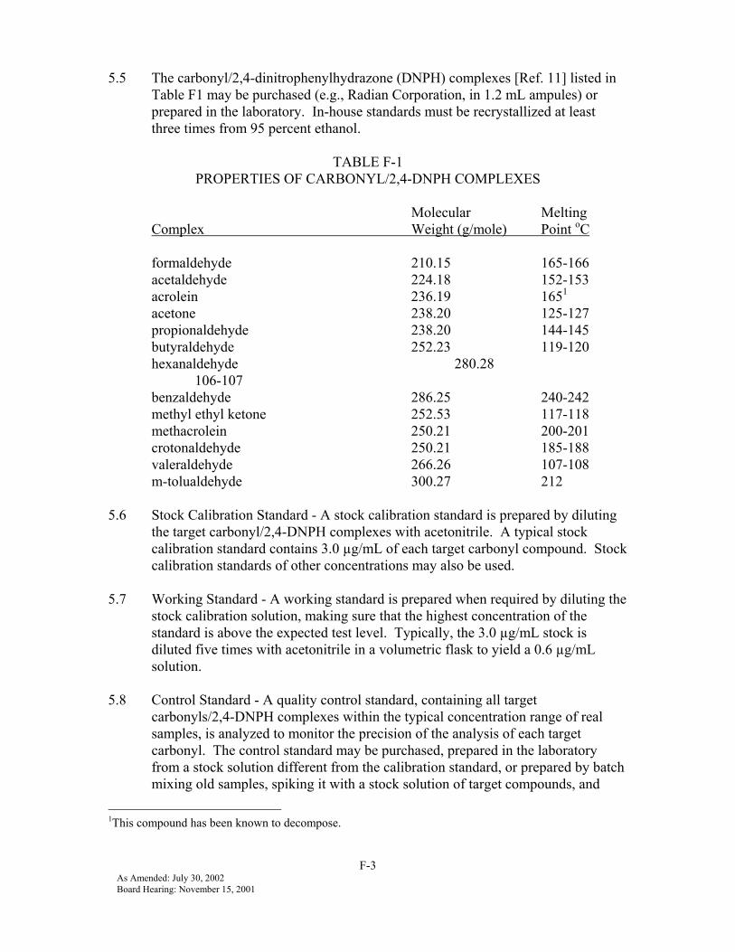
5.5 The carbonyl/2,4-dinitrophenylhydrazone (DNPH) complexes [Ref. 11] listed inTable F1 may be purchased (e.g., Radian Corporation, in 1.2 mL ampules) orprepared in the laboratory. In-house standards must be recrystallized at leastthree times from 95 percent ethanol.
TABLE F-1PROPERTIES OF CARBONYL/2,4-DNPH COMPLEXES
Molecular MeltingComplex Weight (g/mole) Point oC
formaldehyde 210.15 165-166acetaldehyde 224.18 152-153acrolein 236.19 1651
acetone 238.20 125-127propionaldehyde 238.20 144-145butyraldehyde 252.23 119-120hexanaldehyde 280.28
106-107benzaldehyde 286.25 240-242methyl ethyl ketone 252.53 117-118methacrolein 250.21 200-201crotonaldehyde 250.21 185-188valeraldehyde 266.26 107-108m-tolualdehyde 300.27 212
5.6 Stock Calibration Standard - A stock calibration standard is prepared by dilutingthe target carbonyl/2,4-DNPH complexes with acetonitrile. A typical stockcalibration standard contains 3.0 µg/mL of each target carbonyl compound. Stockcalibration standards of other concentrations may also be used.
5.7 Working Standard - A working standard is prepared when required by diluting thestock calibration solution, making sure that the highest concentration of thestandard is above the expected test level. Typically, the 3.0 µg/mL stock isdiluted five times with acetonitrile in a volumetric flask to yield a 0.6 µg/mLsolution.
5.8 Control Standard - A quality control standard, containing all targetcarbonyls/2,4-DNPH complexes within the typical concentration range of realsamples, is analyzed to monitor the precision of the analysis of each targetcarbonyl. The control standard may be purchased, prepared in the laboratoryfrom a stock solution different from the calibration standard, or prepared by batchmixing old samples, spiking it with a stock solution of target compounds, and
1This compound has been known to decompose.

F-4As Amended: July 30, 2002Board Hearing: November 15, 2001
stirring for a minimum of 2 hours. If necessary, the solution is filtered using filterpaper to remove precipitation. All target compounds except acrolein have beenfound to be stable in the control standard.
5.9 Standards used for linearity and LOD determinations (Section 8) may bepurchased or prepared by dilutions of an appropriate level stock solution.
6. PROCEDURE
6.1 For systems collecting the samples via impingers, an absorbing solution isprepared by dissolving 0.11 - 0.13 grams of recrystallized DNPH in 1 L of HPLCgrade acetonitrile. The absorbing solution should be prepared at least every twoweeks. Each batch of acetonitrile used in this procedure is checked foroxygenated impurities by adding it to a contaminant-free dilute solution of DNPHand analyzing by HPLC.
6.1.1 In the laboratory, pipette 15 mL of the DNPH absorbing solution into eachof the 30 mL impingers for each emission test. Add 0.1 mL of 2.85 Nsulfuric acid or 0.15 mL of 3.8 M perchloric acid to each impinger.
6.2 For systems collecting the samples via cartridges, DNPH-impregnated cartridgesshall be sealed and refrigerated, at a temperature less than 40oF, upon receipt frommanufacturer, until ready for use.
6.2.1 At the exhaust volumes being sampled (1 L/min), a back-up cartridge maybe required for CVS phase 1 but no back-up cartridge is needed for CVSphases 2 and 3.
6.3 After sampling uncap and place all impingers in preheated water at 70-80oC for30 minutes (min) to complete derivatization. Heating is not required when usingperchloric acid.
6.3.1 For cartridges, remove the caps and extract with 5 mL acetonitrile,running the extract into glass storage bottles.
6.4 Remove the impingers from the water bath and cool to room temperature.Replace any lost solvent by adding acetonitrile to the 15-mL mark.
6.4.1 Replacing lost solvent is not required when using an internal standardmethod (Section 7.4).
6.5 Transfer the solution from each impinger/cartridge to glass vials and seal withnew septum screw caps.
F-5As Amended: July 30, 2002Board Hearing: November 15, 2001
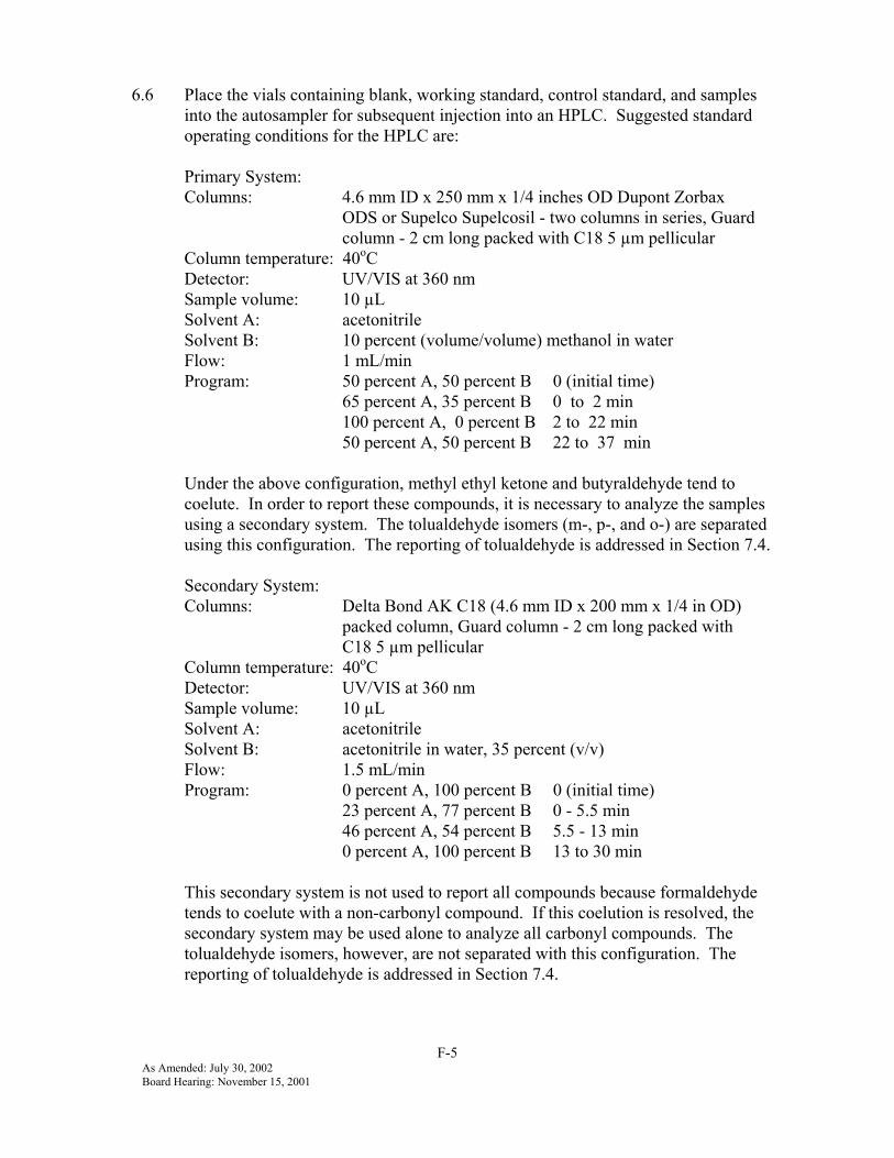
6.6 Place the vials containing blank, working standard, control standard, and samplesinto the autosampler for subsequent injection into an HPLC. Suggested standardoperating conditions for the HPLC are:
Primary System:Columns: 4.6 mm ID x 250 mm x 1/4 inches OD Dupont Zorbax
ODS or Supelco Supelcosil - two columns in series, Guardcolumn - 2 cm long packed with C18 5 µm pellicular
Column temperature: 40oCDetector: UV/VIS at 360 nmSample volume: 10 µLSolvent A: acetonitrileSolvent B: 10 percent (volume/volume) methanol in waterFlow: 1 mL/minProgram: 50 percent A, 50 percent B 0 (initial time)
65 percent A, 35 percent B 0 to 2 min100 percent A, 0 percent B 2 to 22 min50 percent A, 50 percent B 22 to 37 min
Under the above configuration, methyl ethyl ketone and butyraldehyde tend tocoelute. In order to report these compounds, it is necessary to analyze the samplesusing a secondary system. The tolualdehyde isomers (m-, p-, and o-) are separatedusing this configuration. The reporting of tolualdehyde is addressed in Section 7.4.
Secondary System:Columns: Delta Bond AK C18 (4.6 mm ID x 200 mm x 1/4 in OD)
packed column, Guard column - 2 cm long packed withC18 5 µm pellicular
Column temperature: 40oCDetector: UV/VIS at 360 nmSample volume: 10 µLSolvent A: acetonitrileSolvent B: acetonitrile in water, 35 percent (v/v)Flow: 1.5 mL/minProgram: 0 percent A, 100 percent B 0 (initial time)
23 percent A, 77 percent B 0 - 5.5 min46 percent A, 54 percent B 5.5 - 13 min0 percent A, 100 percent B 13 to 30 min
This secondary system is not used to report all compounds because formaldehydetends to coelute with a non-carbonyl compound. If this coelution is resolved, thesecondary system may be used alone to analyze all carbonyl compounds. Thetolualdehyde isomers, however, are not separated with this configuration. Thereporting of tolualdehyde is addressed in Section 7.4.

F-6As Amended: July 30, 2002Board Hearing: November 15, 2001
Data System: The outputs from the UV/VIS detector are sent to a PC-controlleddata acquisition system.
6.7 The peak integrations are corrected as necessary in the data system. Anymisplaced baseline segments are corrected in the reconstructed chromatogram.
6.8 Samples containing compounds having concentrations above the documentedrange of instrument linearity must be diluted and reanalyzed.
7. CALCULATIONS
7.1 For each target carbonyl, the carbonyl mass is calculated from itscarbonyl/2,4-DNPH mass.
7.2 The mass of each carbonyl compound, per impinger or cartridge, is determined bythe following calculation:
( ) ( ) BmLvolumeCartridgeorImpingerFactorResponseAreaPeakMass samplesample ∗∗∗=
where B is the ratio of the molecular weight of the carbonyl compound to its2,4-dinitrophenylhydrazone derivative and where the response factor (RF) foreach carbonyl is calculated during the calibration by:
RF = Concentrationstandard ( µg 2,4-DNPH species/mL)Peak Areastandard
7.3 For tolualdehyde, the sum of all isomers present is reported as m-tolualdehyde.
7.3.1 Under the conditions of the primary system in Section 6.6, the isomers areseparated. The m-tolualdehyde response factor is applied to each peakand the sum reported as m-tolualdehyde.
7.3.2 Under the conditions of the secondary system in Section 6.6, the isomerscoelute. The m-tolualdehyde response factor is applied to the singletolualdehyde peak. This concentration is reported as m-tolualdehyde.
7.4 An internal standard method may also be used.
F-7As Amended: July 30, 2002Board Hearing: November 15, 2001
8. QUALITY CONTROL
8.1 Blank Runs
8.1.1 Reagent Blanks - The solvents used are of the highest HPLC grade and aretested for impurities when a new lot number is used. If this lot number isfound to be acceptable, (no carbonyls present at concentrations at or abovethe LOD), daily blank analysis is not performed.
8.1.2 Carbonyl/2,4-DNPH Purity - The carbonyl/ 2,4- DNPHs are checked forpurity by their melting points and their chromatograms (See Table F-1).Analysis of the solution of carbonyl/2,4-DNPH must yield only the peakof interest. No contaminant peaks above the LOD should be observed.
8.1.3 Field Blanks – One cartridge is analyzed as a field blank for each emissiontest. If the field blank shows a peak greater than the limit of detection(LOD) in the region of interest, the source of the contamination must beinvestigated and remedied.
8.1.4 Cartridge Blanks - At least one cartridge per batch is analyzed as a batchblank. If the cartridge blank shows a peak greater than the limit ofdetection (LOD) in the region of interest, the source of the contaminationmust be investigated and remedied.
8.2 Calibration Run - The calibration standard is analyzed each analysis day togenerate the response factors used to quantify the sample concentrations.
8.3 Control Standard Run - The quality control standard is analyzed at least once eachanalysis day. Measurements of all target compounds in the control standard,except acrolein, must fall within the control limits to ensure the validity of thesample analyses that day. To meet this requirement, it may be necessary to rerunthe calibration and control standards, and inspect and repair the HPLC.
8.4 Control Charts - A quality control chart is maintained for each component of thecontrol standard. The control charts, used on a daily basis, establish that themethod is “in- control.” The following describes how to construct a typicalcontrol chart:
1. Obtain at least 20 daily control standard results,2. Calculate the control standard mean concentration, and standard
deviation(s) for the target analyte, and3. Create a control chart for the target analyte by placing the concentration
on the Y-axis and the date on the X-axis. Establish an upper warning limitand a lower warning limit at two standard deviations (2s) above and belowthe average concentration. Establish an upper control limit and a lower

F-8As Amended: July 30, 2002Board Hearing: November 15, 2001
control limit at three standard deviations (3s) above and below the averageconcentration.
4. Due to the low variability of the carbonyl control standard measurements,a control standard measurement is considered to be out-of-control whenthe analyzed value exceeds either the 3s limit, or the range of ± 10% of themean control measurement, whichever is greater, or if two successivecontrol standard measurements of the same analyte exceed the 2s limit.
5. If 20 control standard measurements are not yet available to create acontrol chart (e.g., the control standard was expended and replaced priorto obtaining 20 points with the new standard), measurements must bewithin 10% of the assay (purchased) or theoretical (prepared in-house)concentration.
The measured concentrations of all target analytes contained in the controlstandard must be within the control limits (in-control) for the sample results to beconsidered acceptable. No control requirements have been established foracrolein, since it has been shown to degrade over time.
8.5 Duplicates - A duplicate analysis of one sample is performed at least once peranalysis day. The relative percent difference (RPD) is calculated for eachduplicate run:
( ) 100tsmeasuremenoriginalandduplicateofAverage
|tsmeasuremenoriginalandduplicatebetweenDifference|%RPD ∗=
For each compound, the allowable RPD depends on the average concentrationlevel for the duplicate runs, as shown in the following table:
F-9As Amended: July 30, 2002Board Hearing: November 15, 2001
Average Measurement for Duplicate Runs Allowable RPD (%)1 to 10 times LOD 10010 to 20 “ “ 3020 to 50 “ “ 20Greater than 50 “ “ 15
If the results of the duplicate analyses do not meet these criteria for all targetcarbonyls, the sample may be reanalyzed. If reanalysis is not feasible or if thecriteria are still not met on reanalysis, all sample results for that analysis day areinvalid.
8.6 Linearity - A multipoint calibration to confirm instrument linearity is performedfor all target analytes for new instruments, after making instrument modificationsthat can affect linearity, and at least once every year. The multipoint calibrationconsists of at least five concentration or mass loading levels (using smaller orlarger volume sample sizes of existing standards is acceptable), each above theLOD, distributed over the range of expected sample concentration. Eachconcentration level is measured at least twice. A linear regression analysis isperformed using concentration and average area counts to determine regressioncorrelation coefficient (r). The r must be greater than 0.995 to be consideredlinear for one point calibrations.
8.7 Limit of Detection - The LOD for the target analytes must be determined for newinstruments, after making instrument modifications which can affect the LOD andat least once per year. To make the calculations, it is necessary to perform amultipoint calibration consisting of at least four “low” concentration levels, eachabove the LOD, with at least five replicate determinations of the lowestconcentration standard. A linear regression is performed and the standarddeviation (in area counts) of the lowest concentration standard determined. Thestandard deviation is converted to concentration units using the slope of the linearregression:
s = sa ÷ m
where m is the slope of the linear regression, s is the standard deviation (inconcentration units) of the lowest concentration standard and sa is the standarddeviation (in area counts) of the lowest concentration standard.
The LOD must be calculated using the following equation [Ref. 12]:
stLOD ∗=
where s is the standard deviation (in concentration units) of at least five replicatedeterminations of the lowest concentration standard and t is the t-factor for 99percent confidence for a one-sided normal (Gaussian) distribution. The number

F-10As Amended: July 30, 2002Board Hearing: November 15, 2001
of degrees of freedom is equal to the number of replicates, minus one. Anabbreviated t-table is:
Degrees of Freedom t-value4 3.75 3.46 3.17 3.0
The lowest standard must be of a concentration of one to five times the estimatedLOD.
8.7.1 The maximum allowable LOD is 0.0075 µg/mL. The calculatedlaboratory LOD must be equal to or lower than the maximum allowableLOD. All peaks identified as target compounds that are equal to or exceedthe maximum allowable LOD must be reported. If the calculatedlaboratory LOD is less than the maximum allowable LOD, the laboratorymay choose to set its reporting limit at the maximum allowable LOD, thecalculated laboratory LOD, or any level in between.
8.7.2 For the purpose of calculating the total mass of all species, theconcentrations of the compounds below the LOD are considered to bezero.

G-1As Amended: July 30, 2002Board Hearing: November 15, 2001
Part GDETERMINATION OF NMOG MASS EMISSIONS
1. INTRODUCTION
1.1 NMOG mass emissions consist of non-methane hydrocarbons and oxygenatedhydrocarbons.
1.2 All definitions and abbreviations are set forth in Appendix 2 of these testprocedures.
2. NMOG WEIGHTED MASS EMISSIONS
2.1 NMOG weighted mass (wm) emissions shall be calculated as follows:
∑ ∑ ∑++= wmwmwmwm RHOROHNMHCNMOG
Non-methane hydrocarbon weighted mass emissions (NMHCwm) can bedetermined by either FID or GC. If the FID method is used to calculateNMHCwm, refer to Part B of these test procedures entitled, “Determination ofNon-Methane Hydrocarbon Mass Emissions by Flame Ionization Detection.”If the GC method is used to calculate NMHCwm, refer to section 3, “SpeciatedHydrocarbon Mass Emissions Calculation” contained herein. Carbonylweighted mass emissions (RHOwm) are to be calculated according to section 5“Carbonyl Mass Emissions Calculation” contained herein. For alcohol fueledvehicles, alcohol weighted mass emissions (ROHwm) are to be calculatedaccording to section 4 “Alcohol Mass Emissions Calculation” containedherein.
3. SPECIATED HYDROCARBON MASS EMISSIONS CALCULATION
3.1 INTRODUCTION
Vehicular exhaust emissions are measured according to the FTP [Ref. 1]. Foreach of the three phases of the FTP, a tedlar bag of 0.5 ft3 capacity is used tocollect a dilute exhaust sample. A fourth 0.5 ft3 tedlar bag is used to collect acomposite dilution air (background) sample from all three phases of the FTP.All bag samples are analyzed according to Method No. 1002 (Part D of thesetest procedures) and Method No. 1003 (Part E of these test procedures) todetermine the dilute exhaust and dilution air concentrations of individualhydrocarbon compounds. The measured hydrocarbon compoundconcentrations are used in the following equations to calculate the weightedmass emissions of each hydrocarbon compound.

G-2As Amended: July 30, 2002Board Hearing: November 15, 2001
3.2 HC MASS EMISSIONS CALCULATION PER TEST PHASE
3.2.1 HCmass n = (HCconc ∗ HCdens ∗ VMIX ∗ 10-6) / (Carbon No.)
3.2.2 HCconc = HCe - (HCd ∗ (1 - (1 / DF)))NOTE: If HCconc is calculated to be less than zero, then HCconc = 0.
3.3. WEIGHTED HC MASS EMISSIONS CALCULATION
3.3.1
++
∗+
++
∗=phase2phase3
mass2mass3
phase2phase1
mass2mass1wm DD
HCHC0.57
DDHCHC
0.43HC
3.4. SAMPLE CALCULATION
3.4.1 Exhaust emissions from a gasoline vehicle are collected in three diluteexhaust sample bags and one dilution air (background) sample bagduring the FTP. Gas chromatography is used to determine the benzeneconcentration of each bag sample. Calculate the weighted benzenemass emissions based on the following data:
TestPhase
HCe(ppbC)
HCd(ppbC)
FID THCe(ppmC)
CH4e(ppmC)
CO2e(%)
COem(ppm)
Ra(%)
VMIX(ft3)
Dphase n(mile)
1 500 25 98 6 1.20 280 28 2846 3.584
2 100 25 22 4 0.95 87 25 4854 3.842
3 120 25 29 5 1.07 101 24 2840 3.586
For Phase 1:
DF = 13.47 / [CO2e + (NMHCe + CH4e + COe ) * 10-4 ](see section 6, DF Calc.)
NMHCe = FID THCe - (rCH4 * CH4e )= 98 ppmC - (1.04 * 6 ppmC)= 92 ppmC
CO = (1 - (0.01 + 0.005 * HCR) * CO2e - 0.000323 * Ra ) * COemNOTE: If a CO instrument which meets the criteria specified in CFR 40,86.111 is used and the conditioning column has been deleted, COem must besubstituted directly for COe .
= (1 - (0.01925) * 1.2% - 0.000323 * 28%) * 280 ppm

G-3As Amended: July 30, 2002Board Hearing: November 15, 2001
= 271 ppmDF = 13.47 / [1.2% + (92 ppmC + 6 ppmC + 271 ppm) * 10-4 ]
= 10.89
HCconc = HCe - (HCd * (1 - (1 / DF)))= 500 ppbC - (25 ppbC * (1 - (1 / 10.89)))= 477 ppbC
Mol. Wt. of C6H6 = (6 * 12.01115) + (6 * 1.00797) = 78.11472 g/mole
HCdens = (Mol. Wt. * conversion of liter to ft3 ) / (Mol. Vol.)= (78.11472 g/mole * 28.316 liter/ft3 ) / 24.055 liter/mole= 91.952 g/ft3
HCmass n = (HCconc * HCdens * VMIX * 10-6 ) / (Carbon No.)
HCmass 1 = (477 ppbC * 91.952 g/ft3 * 2846 ft3 * 10-6 ) / 6 = 20.8 mg
Similarly, for Phase 2: Hcmass = 5.7 mg
and for Phase 3: Hcmass = 4.2 mg
Therefore,
++
∗+
++
∗=phase2phase3
mass2mass3
phase2phase1
mass2mass1wm DD
HCHC0.57
DDHCHC
0.43HC
++
∗+
++
∗=miles3.842miles3.586
mg5.7mg4.20.57miles3.842miles3.584
mg5.7mg20.80.43HCwm
HCwm = 2.3 mg/mile (benzene weighted mass emissions)

G-4As Amended: July 30, 2002Board Hearing: November 15, 2001
4. ALCOHOL MASS EMISSIONS CALCULATION
4.1. INTRODUCTION
Vehicular emissions are measured according to the (FTP [Ref. 1]. For each ofthe three phases of the FTP, a set of two impingers is used to collect alcoholemissions in the dilute exhaust. A fourth set of two impingers is used tocollect a composite dilution air (background) alcohol sample from all threephases of the FTP. All impingers are analyzed according to Method No. 1001to determine the alcohol concentration in each impinger. The measuredalcohol concentrations are used in the following equations to calculate theweighted mass emissions of alcohol compounds.
4.2. ALCOHOL MASS EMISSIONS CALCULATION PER TEST PHASE
4.2.1 ROHmass n = (ROHconc ∗ ROHdens ∗ VMIX * 10-6) / (Carbon No.)
4.2.2 ROHconc = ROHe - (ROHd * (1 - (1 / DF)))NOTE: If ROHconc is calculated to be less than zero, then ROHconc = 0.
4.2.3 ROHe = (Imasse / Ivole) * (Mol. Vol. / Mol. Wt.)
4.2.4 Imasse = (Iconce1 + Iconce2) * DensROH * Ivolr
4.2.5 Ivole = Ivolem * (293.16oK / Itempe) * ( PB / 760 mm Hg)
4.2.6 ROHd = (Imassd / Ivold) * (Mol. Vol. / Mol. Wt.)
4.2.7 Imassd = (Iconcd1 + Iconcd2) * DensROH * Ivolr
4.2.8 Ivold = Ivoldm * (293.16oK / Itempd) * (PB / 760 mm Hg)
4.3. WEIGHTED ALCOHOL MASS EMISSIONS CALCULATION
++
∗+
++
∗=phase2phase3
mass2mass3
phase2phase1
mass2mass1wm DD
ROHROH0.57
DDROHROH
0.43ROH
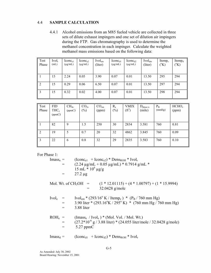
G-5As Amended: July 30, 2002Board Hearing: November 15, 2001
4.4 SAMPLE CALCULATION
4.4.1 Alcohol emissions from an M85 fueled vehicle are collected in threesets of dilute exhaust impingers and one set of dilution air impingersduring the FTP. Gas chromatography is used to determine themethanol concentration in each impinger. Calculate the weightedmethanol mass emissions based on the following data:
TestPhase
Ivolr(mL)
Iconce1(µg/mL)
Iconce2(µg/mL)
Ivolem(liter)
Iconcd1(µg/mL)
Iconcd2(µg/mL)
Ivoldm(liter)
Itempe(oK)
Itempd(oK)
1 15 2.24 0.05 3.90 0.07 0.01 13.50 295 294
2 15 0.29 0.06 6.50 0.07 0.01 13.50 297 294
3 15 0.32 0.02 4.00 0.07 0.01 13.50 298 294
TestPhase
FIDTHCe(ppmC)
CH4e(ppmC)
CO2e(%)
COem(ppm)
Ra(%)
VMIX(ft3)
Dphase n(mile)
PB(mmHg)
HCHOe(ppm)
1 82 9 1.5 250 30 2834 3.581 760 0.81
2 19 5 0.7 20 32 4862 3.845 760 0.09
3 22 6 0.8 32 29 2835 3.583 760 0.10
For Phase 1:Imasse = (Iconce1 + Iconce2) * DensROH * Ivolr
= (2.24 µg/mL + 0.05 µg/mL) * 0.7914 g/mL *15 mL * 106 µg/g
= 27.2 µg
Mol. Wt. of CH3OH = (1 * 12.01115) + (4 * 1.00797) + (1 * 15.9994)= 32.0428 g/mole
Ivole = Ivolem * (293/16o K / Itempe ) * (PB / 760 mm Hg)= 3.90 liter * (293.16oK / 295o K) * (760 mm Hg / 760 mm Hg)= 3.88 liter
ROHe = (Imasse / Ivole ) * (Mol. Vol. / Mol. Wt.)= (27.2*10-6 g / 3.88 liter) * (24.055 liter/mole / 32.0428 g/mole)= 5.27 ppmC
Imassd = (Iconcd1 + Iconcd2) * DensROH * Ivolr

G-6As Amended: July 30, 2002Board Hearing: November 15, 2001
= (0.07 µg/mL + 0.01 µg/mL) * 0.7914 g/ml *15 ml * 106 µg/g
= 0.95 µg
Ivold = Ivoldm * (293.16o K / Itempd ) * ( PB / 760 mm Hg)= 13.50 liter * (293.16oK / 294oK) * (760 mm Hg / 760 mm Hg)= 13.46 liter
ROHd = (Imassd / Ivold) * (Mol. Vol. / Mol. Wt.)= (0.95*10-6 g/ 13.46 liter) * (24.055 liter/mole / 32.0428 g/mole)= 0.05 ppmC
( ) 442 10
02.12−∗+++++
=eeeeee HCHOROHCOCHNMHCCO
DF
(see section 6, DF Calc.)
NMHCe = FID THCe - (rCH4 * CH4e) - (rCH3OH * ROHe )= 82 ppmC - (1.04 * 9 ppmC) - (0.66 * 5.27 ppmC)= 69 ppmC
COe = (1 - (0.01 + 0.005 * HCR) * CO2e - 0.000323 * Ra) * COemNOTE: If a CO instrument which meets the criteria specified in CFR 40,86.111 is used and the conditioning column has been deleted, COem must besubstituted directly for COe .
= (1 - (0.02705) * 1.5% - 0.000323 * 30%) * 250 ppm = 237 ppm
( ) 410ppm0.81ppmC5.27ppmC237ppmC9ppmC691.5%12.02DF −∗+++++
=
ROHconc = ROHe - (ROHd * (1 - (1 / DF))) = 5.27 ppmC - (0.05 ppmC * (1 - (1 / 7.84))) = 5.23 ppmC
ROHdens = (Mol. Wt. * conversion of liter to ft3) / (Mol. Vol.) = (32.0428 g/mole * 28.316 liter/ft) / 24.055 liter/mole = 37.719 g/ft3
ROHmass n = (ROHconc * ROHdens * VMIX * 10-6) / (Carbon No.)ROHmass 1 = (5.23 ppmC * 37.719 g/ft3 * 2834 ft3 * 10-6) / 1
= 0.56 g

G-7As Amended: July 30, 2002Board Hearing: November 15, 2001
Similarly, for Phase 2: ROHmass 2 = 0.08 gand for Phase 3: ROHmass 3 = 0.08 g
Therefore,
++
∗+
++
∗=phase2phase3
mass2mass3
phase2phase1
mass2mass1wm DD
ROHROH0.57
DDROHROH
0.43ROH
++
∗+
++
∗=miles3.845miles3.583
mg0.08mg0.080.57miles3.845miles3.581
mg0.08mg0.560.43ROH wm
ROHwm = 0.05 g (methanol weighted mass emissions)
5. CARBONYL MASS EMISSIONS CALCULATIONS
5.1. INTRODUCTIONVehicular emissions are measured according to the FTP [Ref. 1]. For each ofthe three phases of the FTP, a set of two impingers (or cartridges) is used tocollect carbonyl emissions in the dilute exhaust. A fourth set of twoimpingers (or cartridges) is used to collect a composite dilution air(background) carbonyl sample from all three phases of the FTP. Allimpingers (or cartridges) are analyzed according to Method No. 1004 todetermine the mass of individual carbonyl compounds in each impinger (orcartridge). The measured carbonyl masses are used in the following equationsto calculate the weighted mass emissions of each carbonyl compound.
5.2. CARBONYL MASS EMISSIONS CALCULATION PER TEST PHASE
5.2.1 RHOmass n = (RHOconc * RHOdens * VMIX * 10-6)
5.2.2 RHOconc = RHOe - (RHOd * (1 - (1 / DF)))NOTE: If RHOconc is calculated to be less than zero, then RHOconc = 0.
5.2.3 RHOe = (Imasse / Ivole ) * (Mol. Vol. / Mol. Wt.)
5.2.4 Ivole = Ivolem * (293.16oK / Itempe) * (PB / 760 mm Hg)
5.2.5 RHOd = (Imassd / Ivold) * (Mol. Vol. / Mol. Wt.)
5.2.6 Ivold = Ivoldm * (293.16oK / Itempd) * (PB / 760 mm Hg)
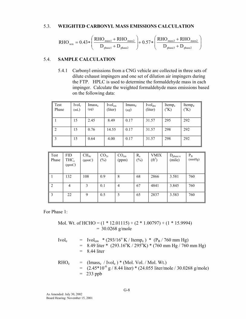
G-8As Amended: July 30, 2002Board Hearing: November 15, 2001
5.3. WEIGHTED CARBONYL MASS EMISSIONS CALCULATION
++
∗+
++
∗=phase2phase3
mass2mass3
phase2phase1
mass2mass1wm DD
RHORHO0.57
DDRHORHO
0.43RHO
5.4. SAMPLE CALCULATION
5.4.1 Carbonyl emissions from a CNG vehicle are collected in three sets ofdilute exhaust impingers and one set of dilution air impingers duringthe FTP. HPLC is used to determine the formaldehyde mass in eachimpinger. Calculate the weighted formaldehyde mass emissions basedon the following data:
TestPhase
Ivolr(mL)
Imasse(µg)
Ivolem(liter)
Imassd(µg)
Ivoldm(liter)
Itempe(oK)
Itempd(oK)
1 15 2.45 8.49 0.17 31.57 295 292
2 15 0.76 14.55 0.17 31.57 298 292
3 15 0.64 4.00 0.17 31.57 298 292
TestPhase
FIDTHCe(ppmC)
CH4e(ppmC)
CO2e(%)
COem(ppm)
Ra(%)
VMIX(ft3)
Dphase n(mile)
PB(mmHg)
1 132 108 0.9 8 68 2866 3.581 760
2 4 3 0.1 4 67 4841 3.845 760
3 22 9 0.5 5 65 2837 3.583 760
For Phase 1:
Mol. Wt. of HCHO = (1 * 12.01115) + (2 * 1.00797) + (1 * 15.9994) = 30.0268 g/mole
Ivole = Ivolem * (293/16o K / Itempe ) * (PB / 760 mm Hg)= 8.49 liter * (293.16oK / 295oK) * (760 mm Hg / 760 mm Hg)= 8.44 liter
RHOe = (Imasse / Ivole ) * (Mol. Vol. / Mol. Wt.)= (2.45*10-6 g / 8.44 liter) * (24.055 liter/mole / 30.0268 g/mole)= 233 ppb

G-9As Amended: July 30, 2002Board Hearing: November 15, 2001
Ivold = Ivoldm * (293.16oK / Itempd) * (PB / 760 mm Hg)= 31.57 liter * (293.16oK / 292oK) * (760 mm Hg / 760 mm Hg)= 31.70 liter
RHOd = (Imassd / Ivold ) * (Mol. Vol. / Mol. Wt.)= (0.17*10-6g / 31.70 liter)*(24.055 liter/mole / 30.0268 g/mole)= 4 ppb
DF = 9.77 / [CO2e + (NMHCe + CH4e + COe) * 10-4](see section 6, DF Calc.)
NMHCe = FID THCe - (rCH4 * CH4e)= 132 ppmC - (1.04 * 108 ppmC)= 20 ppmC
COe = (1 - (0.01 + 0.005 * HCR) * CO2e - 0.000323 * Ra) * COemNOTE: If a CO instrument which meets the criteria specified in CFR 40,86.111 is used and the conditioning column has been deleted, COem must besubstituted directly for COe.
= (1 - 0.02890 * 0.9% - 0.000323 * 68%) * 8 ppm= 7.6 ppm
DF = 9.77 / [0.9% + (20 ppmC + 108 ppmC + 7.6 ppm) * 10-4]= 10.69
RHOconc = RHOe - (RHOd * (1 - (1 / DF)))= 233 ppb - (4 ppb * (1 - (1 / 10.69)))= 229 ppb
RHOdens = (Mol. Wt. * conversion of liter to ft3) / (Mol. Vol.)= (30.0268 g/mole * 28.316 liter/ft3) / 24.055 liter/mole
= 35.35 g/ft3
RHOmass n = (RHOconc * RHOdens * VMIX * 10-6)RHOmass 1 = (229 ppb * 35.35 g/ft3 * 2866 ft3 * 10-6)
= 23.2 mg
Similarly, for Phase 2: RHOmass 2 = 6.6 mgand for Phase 3: RHOmass 3= 12.7 mg
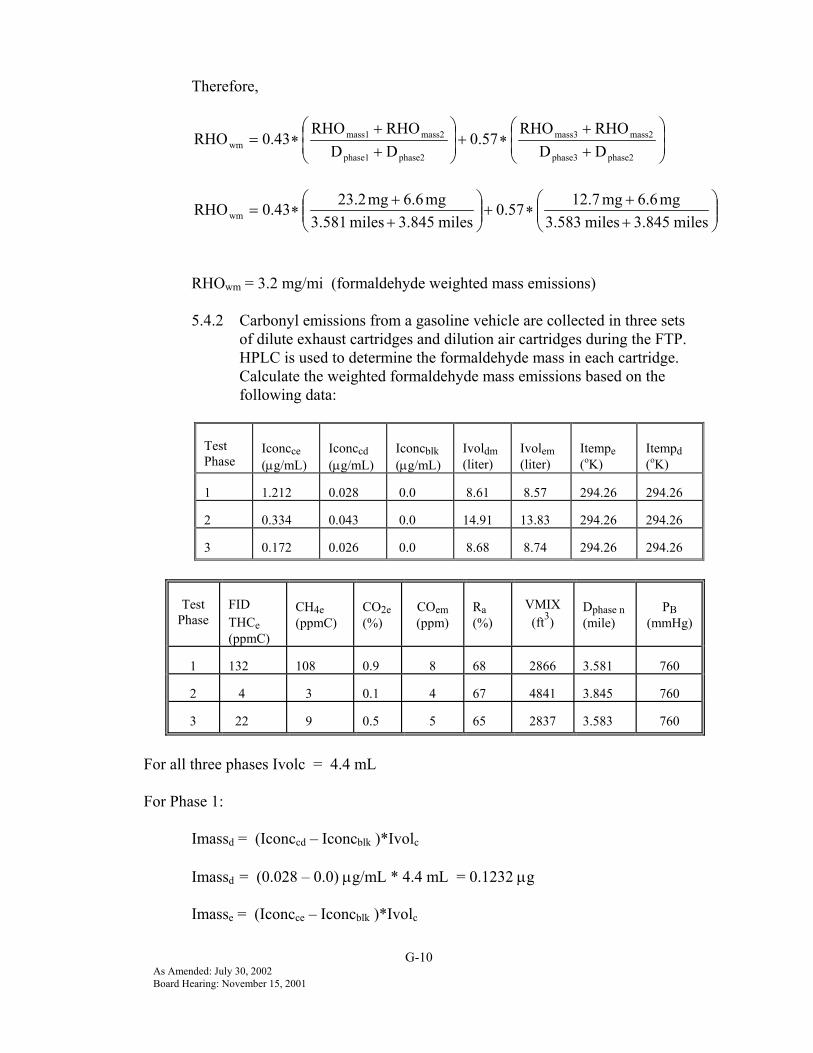
G-10As Amended: July 30, 2002Board Hearing: November 15, 2001
Therefore,
++
∗+
++
∗=phase2phase3
mass2mass3
phase2phase1
mass2mass1wm DD
RHORHO0.57
DDRHORHO
0.43RHO
++
∗+
++
∗=miles3.845miles3.583
mg6.6mg12.70.57miles3.845miles3.581
mg6.6mg23.20.43RHOwm
RHOwm = 3.2 mg/mi (formaldehyde weighted mass emissions)
5.4.2 Carbonyl emissions from a gasoline vehicle are collected in three setsof dilute exhaust cartridges and dilution air cartridges during the FTP.HPLC is used to determine the formaldehyde mass in each cartridge.Calculate the weighted formaldehyde mass emissions based on thefollowing data:
TestPhase
Iconcce(µg/mL)
Iconccd(µg/mL)
Iconcblk(µg/mL)
Ivoldm(liter)
Ivolem(liter)
Itempe(oK)
Itempd(oK)
1 1.212 0.028 0.0 8.61 8.57 294.26 294.26
2 0.334 0.043 0.0 14.91 13.83 294.26 294.26
3 0.172 0.026 0.0 8.68 8.74 294.26 294.26
TestPhase
FIDTHCe(ppmC)
CH4e(ppmC)
CO2e(%)
COem(ppm)
Ra(%)
VMIX(ft3)
Dphase n(mile)
PB(mmHg)
1 132 108 0.9 8 68 2866 3.581 760
2 4 3 0.1 4 67 4841 3.845 760
3 22 9 0.5 5 65 2837 3.583 760
For all three phases Ivolc = 4.4 mL
For Phase 1:
Imassd = (Iconccd – Iconcblk )*Ivolc
Imassd = (0.028 – 0.0) µg/mL * 4.4 mL = 0.1232 µg
Imasse = (Iconcce – Iconcblk )*Ivolc

G-11As Amended: July 30, 2002Board Hearing: November 15, 2001
Imasse = (1.212 – 0.0) µg/mL * 4.4 mL = 5.33 µg
Mol. Wt. of HCHO = (1 * 12.01115) + (2 * 1.00797) + (1 * 15.9994) = 30.0265 g/mole
Ivole = Ivolem * (293/16o K / Itempe ) * (PB / 760 mm Hg)= 8.57 liter * (293.16oK / 294.26oK) * (760 mm Hg / 760 mm Hg)= 8.54 liter
RHOe = (Imasse / Ivole ) * (Mol. Vol. / Mol. Wt.)= (5.33*10-6 g / 8.54 liter) * (24.055 liter/mole / 30.0265 g/mole)= 500 ppb
Ivold = Ivoldm * (293.16oK / Itempd ) * (PB / 760 mm Hg)= 8.61 liter * (293.16oK / 294.26oK) * (760 mm Hg / 760 mm Hg)= 8.58 liter
RHOd = (Imassd / Ivold ) * (Mol. Vol. / Mol. Wt.)= (0.1232*10-6g / 8.58 liter)*(24.055 liter/mole / 30.0265 g/mole)= 11.5 ppb
DF = 9.77 / [CO2e + (NMHCe + CH4e + COe ) * 10-4 ](see section 6, DF Calc.)
NMHCe = FID THCe - (rCH4 * CH4e )= 132 ppmC - (1.04 * 108 ppmC)= 20 ppmC
COe = (1 - (0.01 + 0.005 * HCR) * CO2e - 0.000323 * Ra ) * COemNOTE: If a CO instrument which meets the criteria specified in CFR 40,86.111 is used and the conditioning column has been deleted, COem must besubstituted directly for COe.
= (1 - 0.02890 * 0.9% - 0.000323 * 68%) * 8 ppm= 7.6 ppm
DF = 9.77 / [0.9% + ( 20 ppmC + 108 ppmC + 7.6 ppm) * 10-4 ]= 10.69
RHOconc = RHOe - (RHOd * (1 - (1 / DF)))= 500 ppb - (11.5 ppb * (1 - (1 / 10.69 )))= 489.6 ppb (formaldehyde)
RHOdens = (Mol. Wt. * conversion of liter to ft3 ) / (Mol. Vol.)
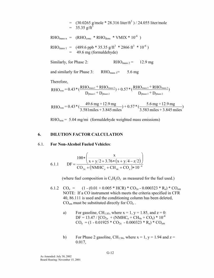
G-12As Amended: July 30, 2002Board Hearing: November 15, 2001
= (30.0265 g/mole * 28.316 liter/ft3 ) / 24.055 liter/mole= 35.35 g/ft3
RHOmass n = (RHOconc * RHOdens * VMIX * 10-6 )
RHOmass 1 = (489.6 ppb * 35.35 g/ft3 * 2866 ft3 * 10-6 )= 49.6 mg (formaldehyde)
Similarly, for Phase 2: RHOmass 2 = 12.9 mg
and similarly for Phase 3: RHOmass 3= 5.6 mg
Therefore,
)D+DRHO+RHO( * 0.57 + )
D+DRHO+RHO( * 0.43 = RHO
2 phase3 phase
2 mass3 mass
2 phase1 phase
2 mass1 masswm
)miles 3.845 + miles3.583
mg 12.9 + mg 5.6( * 0.57 + )miles3.845+3.581miles
mg 12.9 + mg 49.6( * 0.43 = RHOwm
RHOwm = 5.04 mg/mi (formaldehyde weighted mass emissions)
6. DILUTION FACTOR CALCULATION
6.1. For Non-Alcohol Fueled Vehicles:
6.1.1 ( )
( ) 4e4ee2e 10COCHNMHCCO
2z4yx3.762yxx100
DF −∗+++
−+∗++
∗=
(where fuel composition is CxHyOz as measured for the fuel used.)
6.1.2 COe = (1 - (0.01 + 0.005 * HCR) * CO2e - 0.000323 * Ra) * COemNOTE: If a CO instrument which meets the criteria specified in CFR40, 86.111 is used and the conditioning column has been deleted,COem must be substituted directly for COe .
a) For gasoline, CH1.85, where x = 1, y = 1.85, and z = 0:DF = 13.47 / [CO2e + (NMHCe + CH4e + COe) * 10-4
COe = (1 - 0.01925 * CO2e - 0.000323 * Ra) * COem
b) For Phase 2 gasoline, CH1.94, where x = 1, y = 1.94 and z =0.017,

G-13As Amended: July 30, 2002Board Hearing: November 15, 2001
DF = 13.29 / [CO2e + (NMHCe + CH4e + COe) * 10-4
COe = (1 - 0.01970 * CO2e - 0.000323 * Ra) * COem
c) For LPG, CH2.64, where x = 1, y = 2.64, z = 0:DF = 11.68 / [CO2e + (NMHCe + CH4e + COe) * 10-4
COe = (1 - 0.02320 * CO2e - 0.000323 * Ra) * COem
d) For CNG, CH3.78, where x = 1, y = 3.78, and z = 0.016:DF = 9.83 / [[CO2e + (NMHCe + CH4e + COe) * 10-4]COe = (1 - 0.02890 * CO2e - 0.000323 * Ra ) * COem
6.2. For Alcohol Fueled Vehicles:
6.2.1( )
( ) 4eee4ee2e 10HCHOROHCOCHNMHCCO
2z4yx3.762yxx100
DF −∗+++++
−+∗++
∗=
(where fuel composition is CxHyOz as measured for the fuel used.)
6.2.2 COe = (1 - (0.01 + 0.005 * HCR) * CO2e - 0.000323 * Ra ) * COemNOTE: If a CO instrument which meets the criteria specified in CFR40, 86.111 is used and the conditioning column has been deleted,COem must be substituted directly for COe.
a) For M100 (100% methanol), CH3OH, where x = 1, y = 4, and z = 1:DF = 11.57 / [CO2e + (NMHCe + CH4e + COe + ROHe + HCHOe) *10-4]COe = (1 - 0.03000 * CO2e - 0.000323 * Ra ) * COem
b) For M85 (85% methanol, 15% indolene), CH3.41O0.72 , where x = 1, y= 3.41, and z = 0.72:DF = 12.02 / [CO2e + (NMHCe + CH4e + COe + ROHe + HCHOe) *10-4]COe = (1 - 0.02705 * CO2e - 0.000323 * Ra) * COem
c) For E100 (100% ethanol), C2H5OH, where x = 1, y = 3, and z = 0.5:DF = 12.29 / [CO2e + (NMHCe + CH4e + COe + ROHe + HCHOe) *10-4]COe = (1 - 0.02500 * CO2e - 0.000323 * Ra ) * COem

1-1As Amended: July 30, 2002Board Hearing: November 15, 2001
APPENDIX 1
LIST OF COMPOUNDS
CAS # COMPOUND MIR
Alcohols00067-56-1 methanol 0.7100064-17-5 ethanol 1.69
Light End and Mid-Range Hydrocarbons(Listed in approximate elution order)
00074-85-1 ethene 9.0800074-86-2 ethyne 1.2500074-84-0 ethane 0.3100115-07-1 propene 11.5800074-98-6 propane 0.5600463-49-0 1,2-propadiene 12.1600074-99-7 1-propyne 6.4500075-28-5 2-methylpropane 1.3500115-11-7 2-methylpropene 6.3500106-98-9 1-butene 10.2900106-99-0 1,3-butadiene 13.5800106-97-8 n-butane 1.3300624-64-6 trans-2-butene 13.9100463-82-1 2,2-dimethylpropane 1.6800107-00-6 1-butyne 6.2000590-18-1 cis-2-butene 13.2200563-45-1 3-methyl-1-butene 6.9900078-78-4 2-methylbutane 1.6800503-17-3 2-butyne 16.3300109-67-1 1-pentene 7.7900563-46-2 2-methyl-1-butene 6.5100109-66-0 n-pentane 1.5400078-79-5 2-methyl-1,3-butadiene 10.6900646-04-8 trans-2-pentene 10.2300558-37-2 3,3-dimethyl-1-butene 6.0600627-20-3 cis-2-pentene 10.2400689-97-4 1-buten-3-yne 11.0900513-35-9 2-methyl-2-butene 14.4500542-92-7 1,3-cyclopentadiene 7.6100075-83-2 2,2-dimethylbutane 1.3300142-29-0 cyclopentene 7.3800691-37-2 4-methyl-1-pentene 6.26
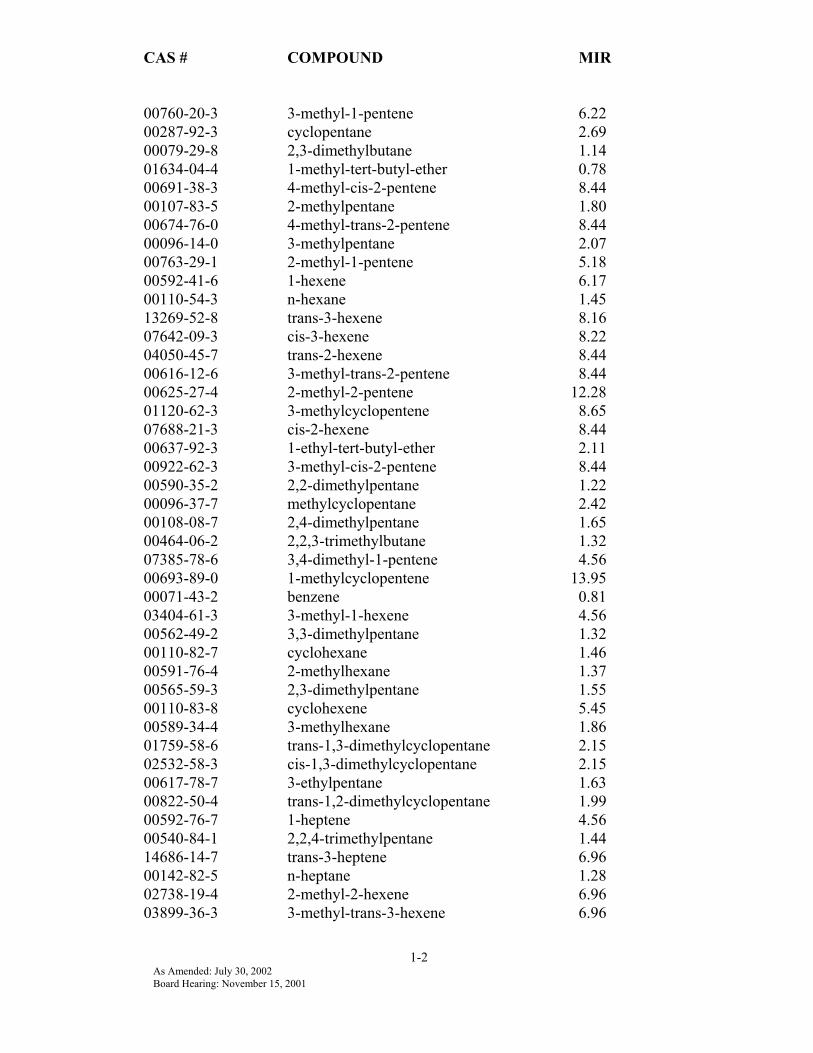
CAS # COMPOUND MIR
1-2As Amended: July 30, 2002Board Hearing: November 15, 2001
00760-20-3 3-methyl-1-pentene 6.2200287-92-3 cyclopentane 2.6900079-29-8 2,3-dimethylbutane 1.1401634-04-4 1-methyl-tert-butyl-ether 0.7800691-38-3 4-methyl-cis-2-pentene 8.4400107-83-5 2-methylpentane 1.8000674-76-0 4-methyl-trans-2-pentene 8.4400096-14-0 3-methylpentane 2.0700763-29-1 2-methyl-1-pentene 5.1800592-41-6 1-hexene 6.1700110-54-3 n-hexane 1.4513269-52-8 trans-3-hexene 8.1607642-09-3 cis-3-hexene 8.2204050-45-7 trans-2-hexene 8.4400616-12-6 3-methyl-trans-2-pentene 8.4400625-27-4 2-methyl-2-pentene 12.2801120-62-3 3-methylcyclopentene 8.6507688-21-3 cis-2-hexene 8.4400637-92-3 1-ethyl-tert-butyl-ether 2.1100922-62-3 3-methyl-cis-2-pentene 8.4400590-35-2 2,2-dimethylpentane 1.2200096-37-7 methylcyclopentane 2.4200108-08-7 2,4-dimethylpentane 1.6500464-06-2 2,2,3-trimethylbutane 1.3207385-78-6 3,4-dimethyl-1-pentene 4.5600693-89-0 1-methylcyclopentene 13.9500071-43-2 benzene 0.8103404-61-3 3-methyl-1-hexene 4.5600562-49-2 3,3-dimethylpentane 1.3200110-82-7 cyclohexane 1.4600591-76-4 2-methylhexane 1.3700565-59-3 2,3-dimethylpentane 1.5500110-83-8 cyclohexene 5.4500589-34-4 3-methylhexane 1.8601759-58-6 trans-1,3-dimethylcyclopentane 2.1502532-58-3 cis-1,3-dimethylcyclopentane 2.1500617-78-7 3-ethylpentane 1.6300822-50-4 trans-1,2-dimethylcyclopentane 1.9900592-76-7 1-heptene 4.5600540-84-1 2,2,4-trimethylpentane 1.4414686-14-7 trans-3-heptene 6.9600142-82-5 n-heptane 1.2802738-19-4 2-methyl-2-hexene 6.9603899-36-3 3-methyl-trans-3-hexene 6.96

CAS # COMPOUND MIR
1-3As Amended: July 30, 2002Board Hearing: November 15, 2001
14686-13-6 trans-2-heptene 7.3300816-79-5 3-ethyl-2-pentene 6.9600107-39-1 2,4,4-trimethyl-1-pentene 3.4510574-37-5 2,3-dimethyl-2-pentene 6.9606443-92-1 cis-2-heptene 6.9600108-87-2 methylcyclohexane 1.9900590-73-8 2,2-dimethylhexane 1.1300107-40-4 2,4,4-trimethyl-2-pentene 5.8501640-89-7 ethylcyclopentane 2.2700592-13-2 2,5-dimethylhexane 1.6800589-43-5 2,4-dimethylhexane 1.8002815-58-9 1,2,4-trimethylcyclopentane 1.7500563-16-6 3,3-dimethylhexane 1.5700565-75-3 2,3,4-trimethylpentane 1.2300560-21-4 2,3,3-trimethylpentane 1.5700108-88-3 toluene 3.9700584-94-1 2,3-dimethylhexane 1.3400592-27-8 2-methylheptane 1.2000589-53-7 4-methylheptane 1.4800589-81-1 3-methylheptane 1.3515890-40-1 (1a,2a,3b)-1,2,3-trimethylcyclopentane 1.7500638-04-0 cis-1,3-dimethylcyclohexane 1.7202207-04-7 trans-1,4-dimethylcyclohexane 1.7503522-94-9 2,2,5-trimethylhexane 1.3302613-65-2 trans-1-methyl-3-ethylcyclopentane 1.7516747-50-5 cis-1-methyl-3-ethylcyclopentane 1.7500111-66-0 1-octene 3.4514850-23-8 trans-4-octene 5.9000111-65-9 n-octane 1.1113389-42-9 trans-2-octene 5.9002207-03-6 trans-1,3-dimethylcyclohexane 1.7207642-04-8 cis-2-octene 5.9001069-53-0 2,3,5-trimethylhexane 1.3302213-23-2 2,4-dimethylheptane 1.4802207-01-4 cis-1,2-dimethylcyclohexane 1.7501072-05-5 2,6-dimethylheptane 1.2501678-91-7 ethylcyclohexane 1.7500926-82-9 3,5-dimethylheptane 1.6300100-41-4 ethylbenzene 2.7903074-71-3 2,3-dimethylheptane 1.2500108-38-3 m-&p-xylene 8.4902216-34-4 4-methyloctane 1.0803221-61-2 2-methyloctane 0.9602216-33-3 3-methyloctane 1.25
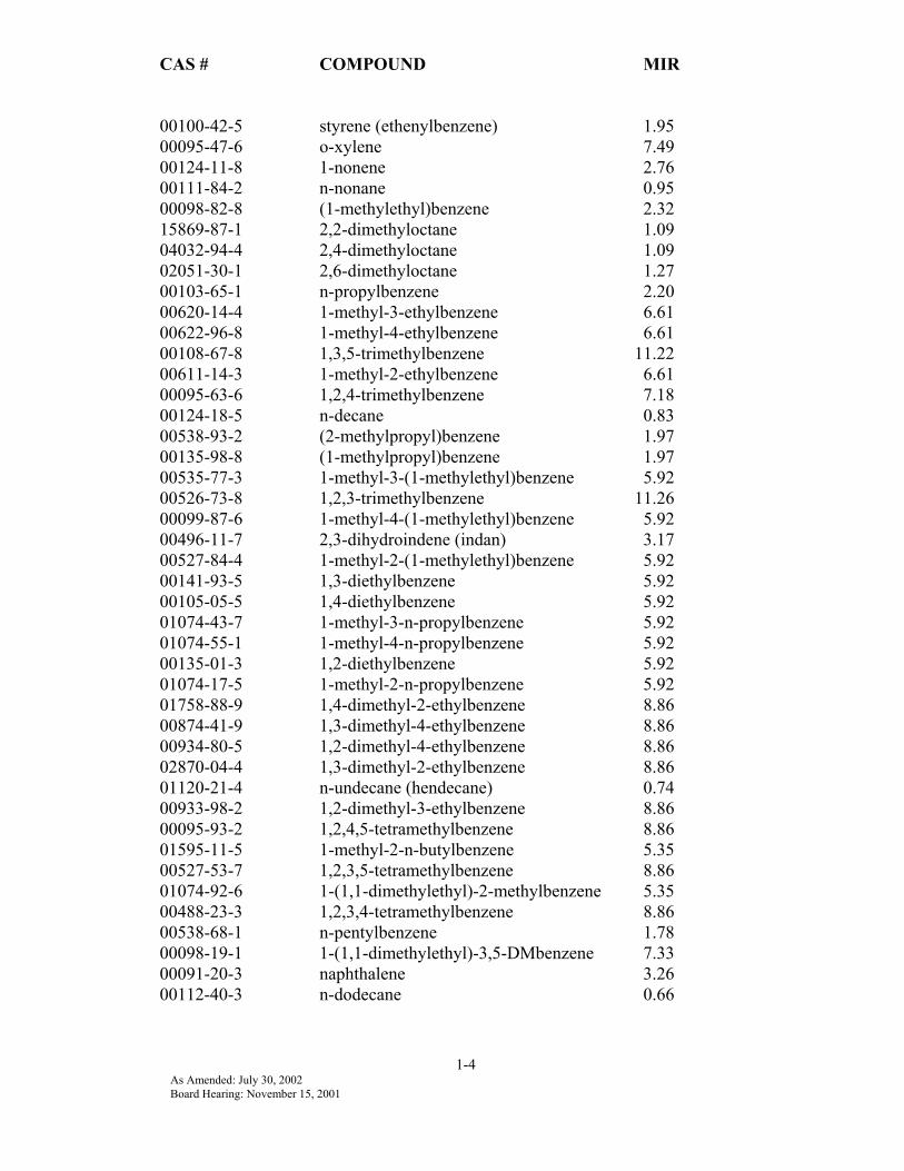
CAS # COMPOUND MIR
1-4As Amended: July 30, 2002Board Hearing: November 15, 2001
00100-42-5 styrene (ethenylbenzene) 1.9500095-47-6 o-xylene 7.4900124-11-8 1-nonene 2.7600111-84-2 n-nonane 0.9500098-82-8 (1-methylethyl)benzene 2.3215869-87-1 2,2-dimethyloctane 1.0904032-94-4 2,4-dimethyloctane 1.0902051-30-1 2,6-dimethyloctane 1.2700103-65-1 n-propylbenzene 2.2000620-14-4 1-methyl-3-ethylbenzene 6.6100622-96-8 1-methyl-4-ethylbenzene 6.6100108-67-8 1,3,5-trimethylbenzene 11.2200611-14-3 1-methyl-2-ethylbenzene 6.6100095-63-6 1,2,4-trimethylbenzene 7.1800124-18-5 n-decane 0.8300538-93-2 (2-methylpropyl)benzene 1.9700135-98-8 (1-methylpropyl)benzene 1.9700535-77-3 1-methyl-3-(1-methylethyl)benzene 5.9200526-73-8 1,2,3-trimethylbenzene 11.2600099-87-6 1-methyl-4-(1-methylethyl)benzene 5.9200496-11-7 2,3-dihydroindene (indan) 3.1700527-84-4 1-methyl-2-(1-methylethyl)benzene 5.9200141-93-5 1,3-diethylbenzene 5.9200105-05-5 1,4-diethylbenzene 5.9201074-43-7 1-methyl-3-n-propylbenzene 5.9201074-55-1 1-methyl-4-n-propylbenzene 5.9200135-01-3 1,2-diethylbenzene 5.9201074-17-5 1-methyl-2-n-propylbenzene 5.9201758-88-9 1,4-dimethyl-2-ethylbenzene 8.8600874-41-9 1,3-dimethyl-4-ethylbenzene 8.8600934-80-5 1,2-dimethyl-4-ethylbenzene 8.8602870-04-4 1,3-dimethyl-2-ethylbenzene 8.8601120-21-4 n-undecane (hendecane) 0.7400933-98-2 1,2-dimethyl-3-ethylbenzene 8.8600095-93-2 1,2,4,5-tetramethylbenzene 8.8601595-11-5 1-methyl-2-n-butylbenzene 5.3500527-53-7 1,2,3,5-tetramethylbenzene 8.8601074-92-6 1-(1,1-dimethylethyl)-2-methylbenzene 5.3500488-23-3 1,2,3,4-tetramethylbenzene 8.8600538-68-1 n-pentylbenzene 1.7800098-19-1 1-(1,1-dimethylethyl)-3,5-DMbenzene 7.3300091-20-3 naphthalene 3.2600112-40-3 n-dodecane 0.66

CAS # COMPOUND MIR
1-5As Amended: July 30, 2002Board Hearing: November 15, 2001
Carbonyl Compounds
00050-00-0 formaldehyde 8.9700075-07-0 acetaldehyde 6.8400107-02-8 acrolein 7.6000067-64-1 acetone 0.4300123-38-6 propionaldehyde 7.8900123-72-8 butyraldehyde 6.7400066-25-1 hexanaldehyde 4.9800100-52-7 benzaldehyde 0.0000078-93-3 methyl ethyl ketone (2-butanone) 1.4900078-85-3 methacrolein 6.2304170-30-3 crotonaldehyde 10.0700110-62-3 valeraldehyde 5.7600620-23-5 m-tolualdehyde 0.00

1-6As Amended: July 30, 2002Board Hearing: November 15, 2001
List of Compounds(Listed by CAS number)
00050-00-0 formaldehyde00064-17-5 ethanol00066-25-1 hexanaldehyde00067-56-1 methanol00067-64-1 acetone00071-43-2 benzene00074-84-0 ethane00074-85-1 ethene00074-86-2 ethyne00074-98-6 propane00074-99-7 1-propyne00075-07-0 acetaldehyde00075-28-5 2-methylpropane00075-83-2 2,2-dimethylbutane00078-78-4 2-methylbutane00078-79-5 2-methyl-1,3-butadiene00078-85-3 methacrolein00078-93-3 methyl ethyl ketone (2-butanone)00079-29-8 2,3-dimethylbutane00091-20-3 naphthalene00095-47-6 o-xylene00095-63-6 1,2,4-trimethylbenzene00095-93-2 1,2,4,5-tetramethylbenzene00096-14-0 3-methylpentane00096-37-7 methylcyclopentane00098-19-1 1-(1,1-dimethylethyl)-3,5-dimethylbenzene00098-82-8 (1-methylethyl)benzene00099-87-6 1-methyl-4-(1-methylethyl)benzene00100-41-4 ethylbenzene00100-42-5 stryrene (ethenylbenzene)00100-52-7 benzaldehyde00103-65-1 n-propylbenzene00105-05-5 1,4-diethylbenzene00106-97-8 n-butane00106-98-9 1-butene00106-99-0 1,3-butadiene00107-00-6 1-butyne00107-02-8 acrolein00107-39-1 2,4,4-trimethyl-1-pentene00107-40-4 2,4,4-trimethyl-2-pentene00107-83-5 2-methylpentane00108-08-7 2,4-dimethylpentane

1-7As Amended: July 30, 2002Board Hearing: November 15, 2001
00108-38-3 m- & p-xylene00108-67-8 1,3,5-trimethylbenzene00108-87-2 methylcyclohexane00108-88-3 toluene00109-66-0 n-pentane00109-67-1 1-pentene00110-54-3 n-hexane00110-62-3 valeraldehyde00110-82-7 cyclohexane00110-83-8 cyclohexene00111-65-9 n-octane00111-66-0 1-octene00111-84-2 n-nonane00112-40-3 n-dodecane00115-07-1 propene00115-11-7 2-methylpropene00123-38-6 propionaldehyde00123-72-8 butyraldehyde00124-11-8 1-nonene00124-18-5 n-decane00135-01-3 1,2-diethylbenzene00135-98-8 (1-methylpropyl)benzene00141-93-5 1,3-diethylbenzene00142-29-0 cyclopentene00142-82-5 n-heptane00287-92-3 cyclopentane00463-49-0 1,2-propadiene00463-82-1 2,2-dimethylpropane00464-06-2 2,2,3-trimethylbutane00488-23-3 1,2,3,4-tetramethylbenzene00496-11-7 2,3-dihydroindene (indan)00503-17-3 2-butyne00513-35-9 2-methyl-2-butene00526-73-8 1,2,3-trimethylbenzene00527-53-7 1,2,3,5-tetramethylbenzene00527-84-4 1-methyl-2-(1-methylethyl)benzene00535-77-3 1-methyl-3-(1-methylethyl)benzene00538-68-1 n-pentylbenzene00538-93-2 (2-methylpropyl)benzene00540-84-1 2,2,4-trimethylpentane00542-92-7 1,3-cyclopentadiene00558-37-2 3,3-dimethyl-1-butene00560-21-4 2,3,3-trimethylpentane00562-49-2 3,3-dimethylpentane00563-16-6 3,3-dimethylhexane00563-45-1 3-methyl-1-butene

1-8As Amended: July 30, 2002Board Hearing: November 15, 2001
00563-46-2 2-methyl-1-butene00565-59-3 2,3-dimethylpentane00565-75-3 2,3,4-trimethylpentane00584-94-1 2,3-dimethylhexane00589-34-4 3-methylhexane00589-43-5 2,4-dimethylhexane00589-53-7 4-methylheptane00589-81-1 3-methylheptane00590-18-1 cis-2-butene00590-35-2 2,2-dimethylpentane00590-73-8 2,2-dimethylhexane00591-76-4 2-methylhexane00592-13-2 2,5-dimethylhexane00592-27-8 2-methylheptane00592-41-6 1-hexene00592-76-7 1-heptene00611-14-3 1-methyl-2-ethylbenzene00616-12-6 3-methyl-trans-2-pentene00617-78-7 3-ethylpentane00620-14-4 1-methyl-3-ethylbenzene00620-23-5 m-tolualdehyde00622-96-8 1-methyl-4-ethylbenzene00624-64-6 trans-2-butene00625-27-4 2-methyl-2-pentene00627-20-3 cis-2-pentene00637-92-3 1-ethyl-tert-butyl-ether00638-04-0 cis-1,3-dimethylcyclohexane00646-04-8 trans-2-pentene00674-76-0 4-methyl-trans-2-pentene00689-97-4 1-buten-3-yne00691-37-2 4-methyl-1-pentene00691-38-3 4-methyl-cis-2-pentene00693-89-0 1-methylcyclopentene00760-20-3 3-methyl-1-pentene00763-29-1 2-methyl-1-pentene00816-79-5 3-ethyl-2-pentene00822-50-4 trans-1,2-dimethylcyclopentane00874-41-9 1,3-dimethyl-4-ethylbenzene00922-62-3 3-methyl-cis-2-pentene00926-82-9 3,5-dimethylheptane00933-98-2 1,2-dimethyl-3-ethylbenzene00934-80-5 1,2-dimethyl-4-ethylbenzene01069-53-0 2,3,5-trimethylhexane01072-05-5 2,6-dimethylheptane01074-17-5 1-methyl-2-n-propylbenzene01074-43-7 1-methyl-3-n-propylbenzene

1-9As Amended: July 30, 2002Board Hearing: November 15, 2001
01074-55-1 1-methyl-4-n-propylbenzene01074-92-6 1-(1,1-dimethylethyl)-2-methylbenzene01120-21-4 n-undecane (hendecane)01120-62-3 3-methylcyclopentene01595-11-5 1-methyl-2-n-butylbenzene01634-04-4 1-methyl-tert-butyl-ether01640-89-7 ethylcyclopentane01678-91-7 ethylcyclohexane01758-88-9 1,4-dimethyl-2-ethylbenzene01759-58-6 trans-1,3-dimethylcyclopentane02051-30-1 2,6-dimethyloctane02207-01-4 cis-1,2-dimethylcyclohexane02207-03-6 trans-1,3-dimethylcyclohexane02207-04-7 trans-1,4-dimethylcyclohexane02213-23-2 2,4-dimethylheptane02216-33-3 3-methyloctane02216-34-4 4-methyloctane02532-58-3 cis-1,3-dimethylcyclopentane02613-65-2 trans-1-methyl-3-ethylcyclopentane02738-19-4 2-methyl-2-hexene02815-58-9 1,2,4-trimethylcyclopentane02870-04-4 1,3-dimethyl-2-ethylbenzene03074-71-3 2,3-dimethylheptane03221-61-2 2-methyloctane03404-61-3 3-methyl-1-hexene03522-94-9 2,2,5-trimethylhexane03899-36-3 3-methyl-trans-3-hexene04032-94-4 2,4-dimethyloctane04050-45-7 trans-2-hexene04170-30-3 crotonaldehyde06443-92-1 cis-2-heptene07385-78-6 3,4-dimethyl-1-pentene07642-04-8 cis-2-octene07642-09-3 cis-3-hexene07688-21-3 cis-2-hexene10574-37-5 2,3-dimethyl-2-pentene13269-52-8 trans-3-hexene13389-42-9 trans-2-octene14686-13-6 trans-2-heptene14686-14-7 trans-3-heptene14850-23-8 trans-4-octene15869-87-1 2,2-dimethyloctane15890-40-1 (1a,2a,3b)-1,2,3-trimethylcyclopentane16747-50-5 cis-1-methyl-3-ethylcyclopentane

2-1As Amended: July 30, 2002Board Hearing: November 15, 2001
APPENDIX 2
DEFINITIONS AND COMMONLY USED ABBREVIATIONS
I. The abbreviations and definitions set forth in this section apply toParts A through G of these test procedures:
ASTM = American Society for Testing and Materials
Carbon No. = number of carbon atoms in the hydrocarbon or organiccompound being measured.
CCR = California Code of Regulations
CH3OHd = the methanol concentration in the dilution air as determinedfrom the dilution air methanol sample using the procedurespecified in Method No. 1001, ppmC.
CH3OHe = the methanol concentration in the dilute exhaust as determinedfrom the dilute exhaust methanol sample using the procedurespecified in Method No. 1001, ppmC.
CH4d = the methane concentration in the dilution air, ppmC.
CH4e = the methane concentration in the dilute exhaust, ppmC.
C2H5OHd = the ethanol concentration in the dilution air as determined fromthe dilution air ethanol sample using the procedure specified inMethod No. 1001, ppmC.
C2H5OHe = the ethanol concentration in the dilute exhaust as determinedfrom the dilute exhaust ethanol sample using the procedurespecified in Method No. 1001, ppmC.
CNG = compressed natural gas
COe = the carbon monoxide concentration in the dilute exhaustcorrected for carbon dioxide and water removal, ppm.
COem = the carbon monoxide concentration in the dilute exhaustuncorrected for carbon dioxide and water removal, ppm.
CO2e = the carbon dioxide concentration in the dilute exhaust, %.
CVS = constant volume sampler

2-2As Amended: July 30, 2002Board Hearing: November 15, 2001
Dphase n = the distance driven by the test vehicle on a chassisdynamometer during test phase n (where n is either 1, 2, or 3),mile.
DensROH = density of alcohol, g/mL.
DF = dilution factor (see Dilution Factor Calculation).
FID = flame ionization detector
FID THCd = the total hydrocarbon concentration including methane andmethanol (for methanol-fueled engines) or ethanol (forethanol-fueled engines) in the dilution air as measured by theFID, ppmC.
FID THCe = the total hydrocarbon concentration including methane andmethanol (for methanol-dueled engines) or ethanol (forethanol-fueled engines) in the dilution exhaust as measured bythe FID, ppmC.
FTP = Federal Test Procedure
GC = gas chromatograph
GC/MS = gas chromatography/mass spectrometry
HCconc = net concentration of an HC compound in the dilute exhaustcorrected for background per test phase, ppbC.
HCd = composite concentration of an HC compound in the dilution air(background) for all three test phases as determined from thecomposite dilution air sample using the procedure specified inMethod No. 1002 and Method No. 1003, ppbC.
HCdens = mass per unit volume of an HC compound corrected tostandard conditions (293.16 K and 760 mm Hg) g/ft3.
HCe = concentration of an HC compound in the dilute exhaust per testphase as determined from the dilute exhaust sample using theprocedure specific in Method No. 1002 and Method No. 1003,ppbC.
HCmass n = mass emissions of an HC compound per test phase n (where nis either 1, 2, or 3), mg.
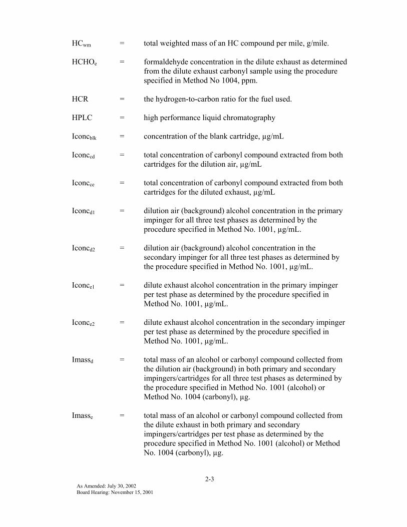
2-3As Amended: July 30, 2002Board Hearing: November 15, 2001
HCwm = total weighted mass of an HC compound per mile, g/mile.
HCHOe = formaldehyde concentration in the dilute exhaust as determinedfrom the dilute exhaust carbonyl sample using the procedurespecified in Method No 1004, ppm.
HCR = the hydrogen-to-carbon ratio for the fuel used.
HPLC = high performance liquid chromatography
Iconcblk = concentration of the blank cartridge, µg/mL
Iconccd = total concentration of carbonyl compound extracted from bothcartridges for the dilution air, µg/mL
Iconcce = total concentration of carbonyl compound extracted from bothcartridges for the diluted exhaust, µg/mL
Iconcd1 = dilution air (background) alcohol concentration in the primaryimpinger for all three test phases as determined by theprocedure specified in Method No. 1001, µg/mL.
Iconcd2 = dilution air (background) alcohol concentration in thesecondary impinger for all three test phases as determined bythe procedure specified in Method No. 1001, µg/mL.
Iconce1 = dilute exhaust alcohol concentration in the primary impingerper test phase as determined by the procedure specified inMethod No. 1001, µg/mL.
Iconce2 = dilute exhaust alcohol concentration in the secondary impingerper test phase as determined by the procedure specified inMethod No. 1001, µg/mL.
Imassd = total mass of an alcohol or carbonyl compound collected fromthe dilution air (background) in both primary and secondaryimpingers/cartridges for all three test phases as determined bythe procedure specified in Method No. 1001 (alcohol) orMethod No. 1004 (carbonyl), µg.
Imasse = total mass of an alcohol or carbonyl compound collected fromthe dilute exhaust in both primary and secondaryimpingers/cartridges per test phase as determined by theprocedure specified in Method No. 1001 (alcohol) or MethodNo. 1004 (carbonyl), µg.

2-4As Amended: July 30, 2002Board Hearing: November 15, 2001
Itempd = dilution air temperature at the flowmeter inlet forimpinger/cartridge sampling, oK.
Itempe = dilute exhaust temperature at the flowmeter inlet forimpinger/cartridge sampling, oK.
Ivolc = elution volume of the cartridge, mL(The cartridge is extracted with 5 mL acetonitrile, but 0.6 mLis retained in the cartridge, so the elution volume is 4.4 mL.)
Ivold = total volume of dilution air (background) drawn through theimpingers/cartridges for all three test phases corrected tostandard conditions (293.16oK and 760 mm Hg), liter.
Ivoldm = total volume of dilution air (background) drawn through theimpingers/cartridges for all three test phases as measuredduring testing, liter.
Ivole = total volume of dilute exhaust drawn through theimpingers/cartridges per test phase corrected to standardconditions (293.16oK and 760 mm Hg), liter.
Ivolem = total volume of dilute exhaust drawn through theimpingers/cartridges per test phase as measured during testing,liter.
Ivolr = volume of the reagent used in an impinger, mL.
LOD = limit of detection
LPG = liquified petroleum gas
Mol. Vol. = molecular volume which is 24.055 liter/mole at standardconditions (293.16oK and 760 mm Hg).
Mol. Wt. = molecular weight of the compound being measured, g/mole.
NIST = National Institute of Standards and Technology
NMHC = non-methane hydrocarbons
NMHCconc = the non-methane hydrocarbon concentration in the diluteexhaust corrected for background, ppmC.
NMHCd = the non-methane hydrocarbon concentration in the dilution aircorrected for methane and alcohol removal, ppmC.
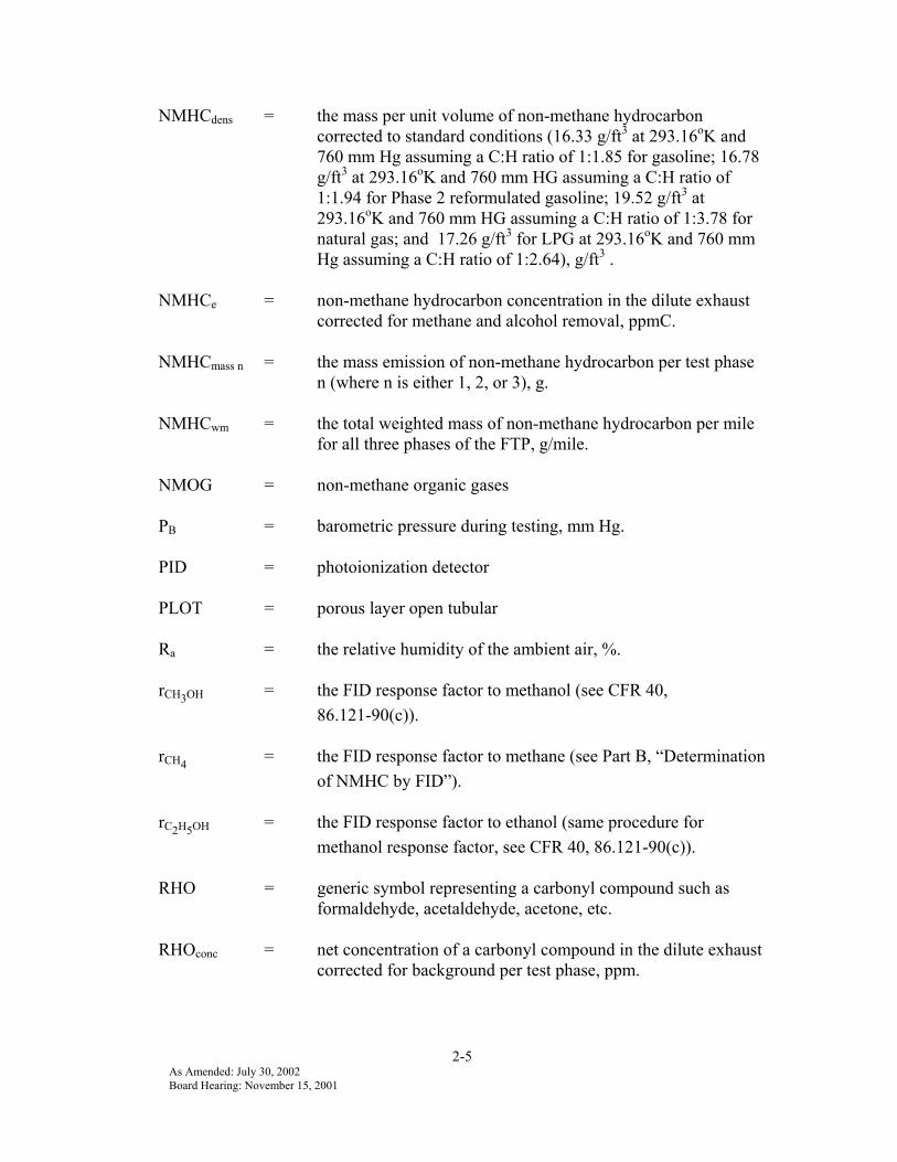
2-5As Amended: July 30, 2002Board Hearing: November 15, 2001
NMHCdens = the mass per unit volume of non-methane hydrocarboncorrected to standard conditions (16.33 g/ft3 at 293.16oK and760 mm Hg assuming a C:H ratio of 1:1.85 for gasoline; 16.78g/ft3 at 293.16oK and 760 mm HG assuming a C:H ratio of1:1.94 for Phase 2 reformulated gasoline; 19.52 g/ft3 at293.16oK and 760 mm HG assuming a C:H ratio of 1:3.78 fornatural gas; and 17.26 g/ft3 for LPG at 293.16oK and 760 mmHg assuming a C:H ratio of 1:2.64), g/ft3 .
NMHCe = non-methane hydrocarbon concentration in the dilute exhaustcorrected for methane and alcohol removal, ppmC.
NMHCmass n = the mass emission of non-methane hydrocarbon per test phasen (where n is either 1, 2, or 3), g.
NMHCwm = the total weighted mass of non-methane hydrocarbon per milefor all three phases of the FTP, g/mile.
NMOG = non-methane organic gases
PB = barometric pressure during testing, mm Hg.
PID = photoionization detector
PLOT = porous layer open tubular
Ra = the relative humidity of the ambient air, %.
rCH3OH = the FID response factor to methanol (see CFR 40,86.121-90(c)).
rCH4 = the FID response factor to methane (see Part B, “Determinationof NMHC by FID”).
rC2H5OH = the FID response factor to ethanol (same procedure formethanol response factor, see CFR 40, 86.121-90(c)).
RHO = generic symbol representing a carbonyl compound such asformaldehyde, acetaldehyde, acetone, etc.
RHOconc = net concentration of a carbonyl compound in the dilute exhaustcorrected for background per test phase, ppm.

2-6As Amended: July 30, 2002Board Hearing: November 15, 2001
RHOd = composite concentration of a carbonyl compound in thedilution air (background) for all three test phases, ppm.
RHOdens = mass per unit volume of a carbonyl compound corrected tostandard conditions (293.16oK and 760 mm Hg), g/ft3.
RHOe = concentration of a carbonyl compound in the dilute exhaust pertest phase, ppm.
RHOmass n = mass emissions of a carbonyl compound per test phase n(where n is either 1, 2, or 3), g.
RHOwm = total weighted mass emissions of a carbonyl compound permile, g/mile.
ROH = generic symbol representing an alcohol compound such asmethanol or ethanol.
ROHconc = net concentration of an alcohol compound in the dilute exhaustcorrected for background per test phase, ppm.
ROHd = composite concentration of an alcohol compound in thedilution air (background) for all three test phases, ppm.
ROHdens = mass per unit volume of an alcohol compound corrected tostandard conditions (293.16oK and 760 mm Hg), g/ft3.
ROHe = concentration of an alcohol compound in the dilute exhaust pertest phase, ppmC.
ROHmass n = mass emissions of an alcohol compound per test phase n(where n is either 1, 2, or 3), g.
ROHwm = total weighted mass emissions of an alcohol compound permile, g/mile.
SAE = Society of Automotive Engineers
SRM = Standard Reference Material
VMIX = the total dilute exhaust volume measured per test phase andcorrected to standard conditions (293.16oK and 760 mm Hg),ft3.

2-7As Amended: July 30, 2002Board Hearing: November 15, 2001
II. The following list is commonly used measurement abbreviations:
g = gramµg = microgramm = metercm = centimeterµm = micrometerµ = micronL = litermL = milliliterµL = microliterppb = parts per billion.ppbC = parts per billion carbon equivalent.ppm = parts per million.ppmC = parts per million carbon equivalent.
Appendix 33-1
APPENDIX 3
REFERENCES
[1] Code of Federal Regulations, Title 40, Part 86, Subpart B
[2] SAE J254, “Instrumentation and Techniques for Exhaust GasEmissions Measurement”
[3] SAE J1094a, “Constant Volume Sampler System for ExhaustEmissions Measurement”
[4] SAE 770141, “Optimization of a Flame Ionization Detector forDetermination of Hydrocarbons in Diluted Automotive Exhausts”.G.D. Reschke, Vehicle Emissions Laboratory, General Motors ProvingGround
[5] SAE J1154, “Methane Measurement Using Gas Chromatography,”(revised December 1991)
[6] U.S. Environmental Protection Agency, Characterization of ExhaustEmissions from Methanol and Gasoline Fueled Automobiles, EPA460/3-82-004.
[7] U.S. Environmental Protection Agency, Compendium of Methods forthe Determination of Toxic Organic Compounds in Ambient Air,(Method T03-15) EPA-600/4-89-017 Research Triangle Park, NorthCarolina, June, 1989.
[8] Standard Test Method for C1 through C6 Hydrocarbons in theAtmosphere by Gas Chromatography, American Standards for TestingMaterials (ASTM) Standards on Chromatography (1981).
[9] U.S. Environmental Protection Agency, Compendium of Methods forthe Determination of Toxic Organic Compounds in Ambient Air,(Method T03-15) EPA-600/4-84-041 Research Triangle Park, NorthCarolina, April, 1989.
[10] Hull, L.A., Procedures for 2,4-DinitrophenylhydrazoneAldehyde-Ketone Air Analysis, Internal Report at U.S. EPA.
[11] Shriner, R.L. and Fuson, R.C., Identification of Organic Compounds,2nd. Ed., John Wiley and Sons, Inc., 1940, p. 143.
[12] Keith, L. H., Taylor, J.K., et al, “Principles of EnvironmentalAnalysis”, Analytical Chemistry, Vol. 55, No. 14, December 1983.