testing and design of bridge deck- column-rocking...
TRANSCRIPT
Testing and design of bridge deck- column-rocking foundation systems
Bruce L. Kutter, Lijun Deng and Sashi M. Kunnath
Caltrans‐PEER Seismic Research Seminar, Sacramento8 June 2009
System conceptsCentrifuge tests and resultsGood observed performance of rocking foundationsDraft design procedureConclusions, questions, and future work

Units: mmIn prototype setup
Column elements: beamWithHingesTop pin elements: nonlinear rot. springsFoundation elements: Qzsimple1, EPP...
X100911
12
13
500921
22
23
31
32
33
Y
Z
311
312
313
333332
331
(11)
(12)
(13)
(21)
(22)
(23)
(33) (34)
(311)
(313)(312)
(333)
(331)
(332)
(120) (220)120 220
313131
42
3131 41
43
44
45
46
47
48
49
50
(411)
(412)
(413)
(414)
(415)
(416)
(417)
(418)
(419)
(420)
(421)
(422)
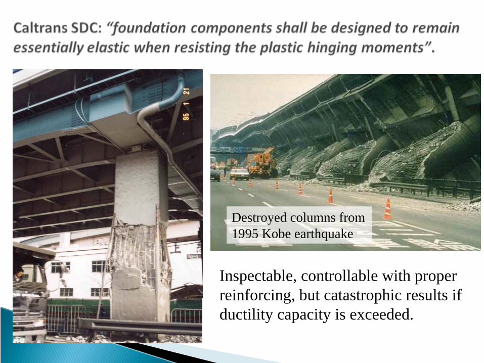
Destroyed columns from 1995 Kobe earthquake
Inspectable, controllable with proper reinforcing, but catastrophic results if ductility capacity is exceeded.
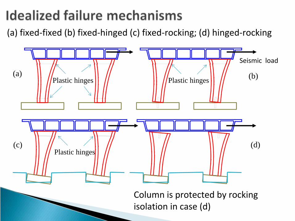
(a) fixed‐fixed (b) fixed‐hinged (c) fixed‐rocking; (d) hinged‐rocking
(b)
Seismic load
Plastic hinges Plastic hinges
(d)Plastic hinges
Column is protected by rocking
isolation in case (d)
(a)
(c)
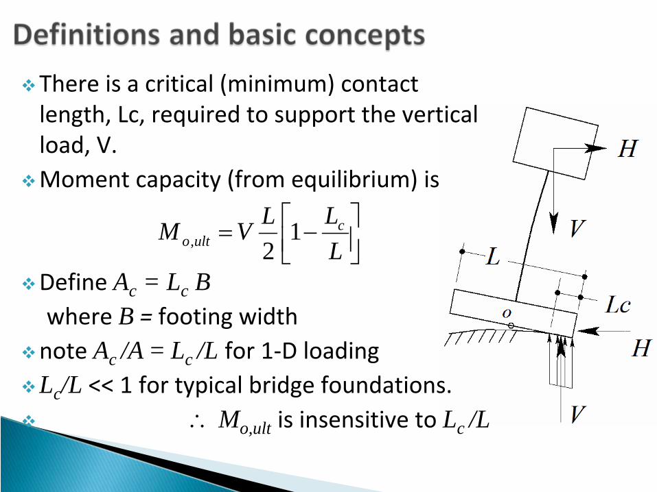
There is a critical (minimum) contact length, Lc, required to support the vertical load, V. Moment capacity (from equilibrium) is
Define Ac = Lc Bwhere B =
footing width
note Ac /A = Lc /L for 1‐D loadingLc/L << 1 for typical bridge foundations.
∴ Mo,ult is insensitive to Lc /L
⎥⎦⎤
⎢⎣⎡ −=
LLLVM c
ulto 12,

7
6774
3660
1680
Unit: mm
8956
I-15
Camino del Norte Rd
I-15
Camino del Norte Rd
169.
35
91.5 Unit: mm
Camino del Norte bridge, San Diego, CA
Prototype
mdeck , Kz , Kθ
Hcol , Kcol
Notches
Structural hinges
L/D=3, and 4.5
R0.5
4.53
2 68
0.5 0.5
R1.5Clear holes for 5/16-18screws 42 places
1.3
0.5
1.5" radius, typical 4 places
Model
Plan view of model bridge deck


1.5 1 0.5 0 0.5
1 .104
0
1 .104
Moment vs rotationTheo ftg moment capTheo ftg moment cap
Foot
ing
mom
ent (
kN*m
)
1 .5 1 0.5 0 0.5
1 .104
0
1 .104
Moment vs rotationTheo ftg moment capTheo ftg moment cap
Footing rotation (%)
Foot
ing
mom
ent (
kN*m
)
2 0 21.5 .104
1 .104
5000
0
5000
1 .104
1.5 .104
Centrifuge tes tsStatic loading tests
g ,
Col
umn
mom
ent (
kN*m
)
2 0 21.5 .104
1 .104
5000
0
5000
1 .104
1.5 .104
Centrifuge tes tsStatic loading tests
Column rotation (%)
Col
umn
mom
ent (
kN*m
)
Footing Rotation (%) Column Rotation (%)
Small- footing bridge
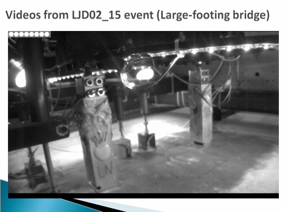
Large- footing bridge
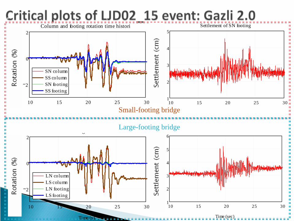
10 15 20 25 30
2
0
2
SN columnSS columnSN footingSS footing
Column and footing rotation time histori
Rot
atio
n (%
)
10 15 20 25 301
2
3
4
5Settlement of SN footing
Sett
lem
ent (
cm)
10 15 20 25 30
2
0
2
LN columnLS columnLN footingLS footing
g
Time (s)
Rot
atio
n (%
)
10 15 20 25 301
2
3
4
5
6g
Time (sec)
Sett
lem
ent (
cm)
Small-footing bridge
Large-footing bridge

Systems with small footings may perform better than systems with large footingsdrift, ductility demand on columns
Rocking foundations provideSelf‐centering tendencyNon‐degrading moment capacityIsolation mechanismEnergy dissipation
Difficult aspect of the problem: How to evaluate settlement (or uplift) associated with rocking.
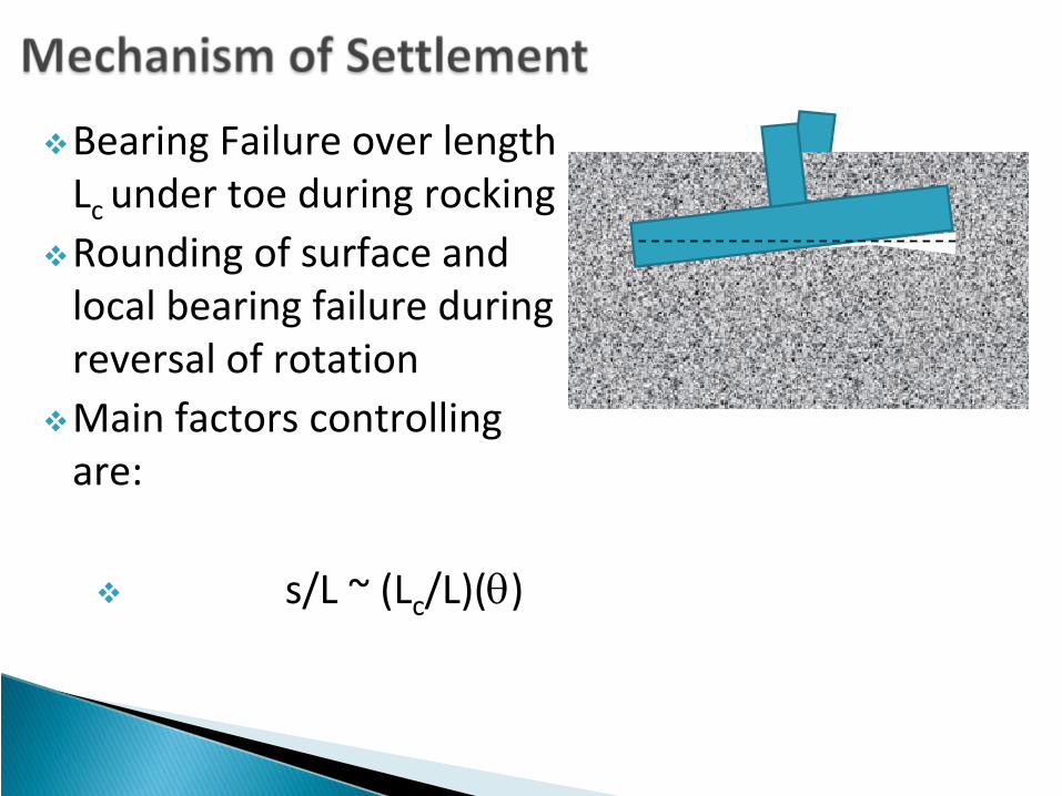
Lc
Bearing Failure over length Lc under toe during rockingRounding of surface and local bearing failure during reversal of rotationMain factors controlling are:
s/L ~ (Lc/L)(θ)
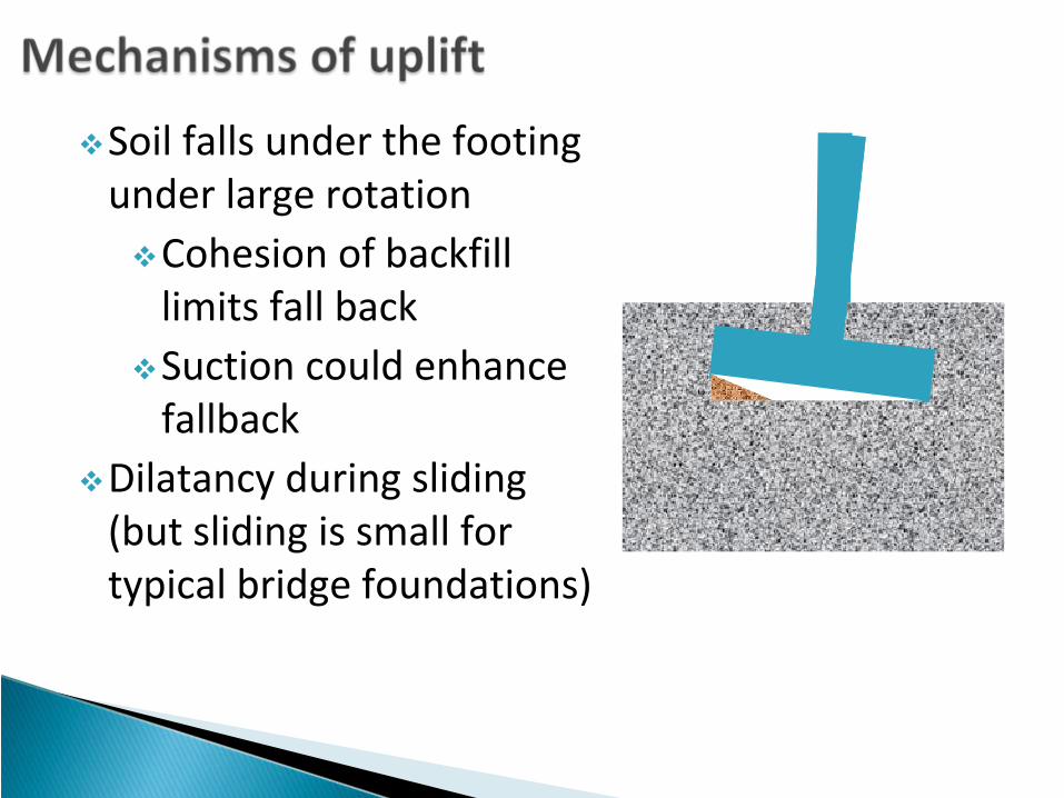
Soil falls under the footing under large rotation
Cohesion of backfill limits fall backSuction could enhance fallback
Dilatancy during sliding (but sliding is small for typical bridge foundations)

Small FSvLarge FSv
Settlement per cycle, s/L Uplift, -s/L
Half Amplitude of Rotation (radians)
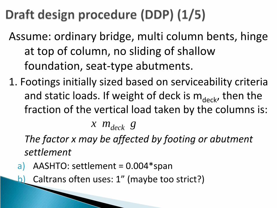
Assume: ordinary bridge, multi column bents, hinge at top of column, no sliding of shallow
foundation, seat‐type abutments.1. Footings initially sized based on serviceability criteria
and static loads. If weight of deck is mdeck
, then the fraction of the vertical load taken by the columns is: x mdeck g
The factor x may be affected by footing or abutment settlement
a)
AASHTO: settlement = 0.004*spanb)
Caltrans
often uses: 1”
(maybe too strict?)

3. Compute rocking acceleration
And “Rocking Force”:
hdeckr amF =
2. Ground motion selectiona)
ARS may be sufficient for MCE, safety evaluation
b)
Time histories for Functional‐Evaluation Earthquake (FEE)
(MTD 20‐1 1999)
mdeck * ah
mdeck/2 * g
Assume half deck weight shared equally by columns
mdeck * g/4
mdeck * ah/2 Mc_foot
mdeck * g/4Mc_foot
Hdcg
LfcH
hdeckam21
gmxdeck2
gmxdeck2
gxmdeck
cc
c
h
HLxLL
HLx
ga
2)/1(
2≈−=

4. Drift demand in MCE
a)
Estimate using ARS
b)
Nonlinear dynamic analysis of SDOF;
BISPEC example:PGA = 0.45g Rocking acceleration = 0.13g
ARS
Demand
Rocking
Force
Δrock ΔD
Relativ
e Horizon
tal
Displacem
ent (in.) Time (s)
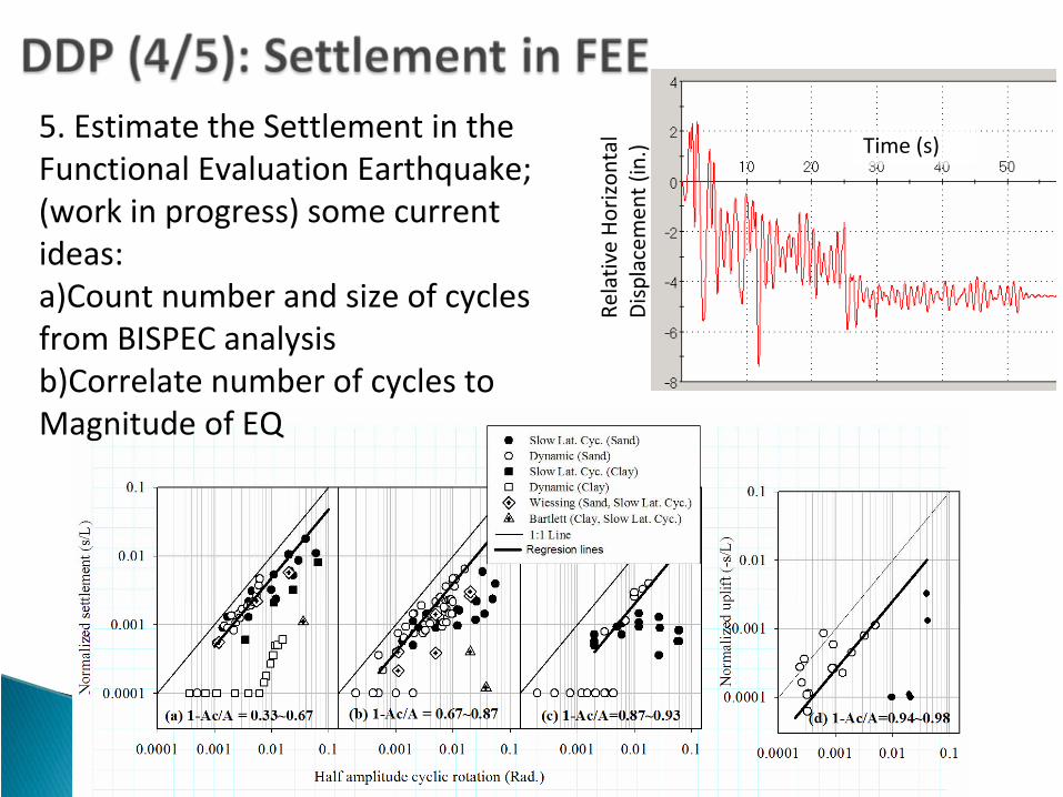
5. Estimate the Settlement in the
Functional Evaluation Earthquake;
(work in progress) some current
ideas:a)Count number and size of cycles
from BISPEC analysisb)Correlate number of cycles to
Magnitude of EQ
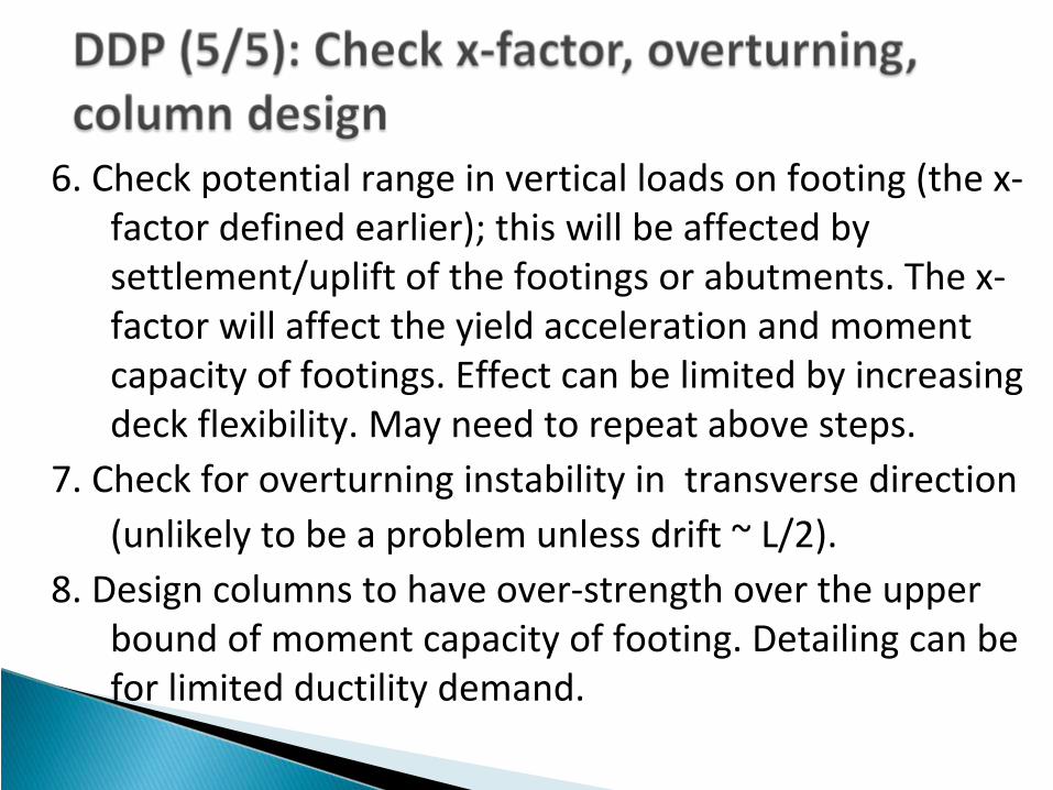
6. Check potential range in vertical loads on footing (the x‐ factor defined earlier); this will be affected by
settlement/uplift of the footings or abutments. The x‐ factor will affect the yield acceleration and moment
capacity of footings. Effect can be limited by increasing deck flexibility. May need to repeat above steps.
7. Check for overturning instability in transverse direction (unlikely to be a problem unless drift ~ L/2).
8. Design columns to have over‐strength over the upper bound of moment capacity of footing. Detailing can be
for limited ductility demand.

Performance of bridges on small rocking foundations can be superior to that on larger foundations. What is the allowable settlement?Statically: 1” seems smallFunctional Evaluation Earthquake: 0.004 x span (AASHTO)MCE: avoid collapse due to excessive bending of deck
Working on simplified procedures to estimate drift/rotation demand and associated settlementWorking on an example design procedure, with real numbersOne more centrifuge testNonlinear finite element simulations (parametric studies on soil‐fdn‐col‐deck‐abutment systems. )

Financial support from California Department of Transportation and PEERCaltrans collaborators Mark Desalvatore, Steve McBride, Tom Shantz, Mahmoud Khojasteh, Craig Whitten, FadelAlameddinePEER collaborators – Steve Mahin, Tara Hutchinson, Boris JeremicNSF: NEES (Network for Earthquake Engineering Simulation): NEES@UCDavisUCD students: Tom Algie , Jose Ugalde, and SivapalanGajan, Emrah Erduran, Yunlei Fan