testing of dlr c/c-sic for hifire 8 scramjet combustorelib.dlr.de/87092/1/130625 dlr dcr tests...
TRANSCRIPT

1 Approved For Public Release
Testing of DLR C/C-SiC for HIFiRE 8 Scramjet Combustor
7th European Workshop on Thermal Protection Systems and Hot Structures 8-10 April 2013
ESA/ESTEC, Noordwijk, The Netherlands
David E. Glass MS 190, NASA Langley Research Center, Hampton, VA 23681 USA
Diego P. Capriotti MS 168, NASA Langley Research Center, Hampton, VA 23681 USA
Thomas Reimer and Marius Kütemeyer Deutsches Zentrum für Luft- und Raumfahrt (DLR), Pfaffenwaldring 38-40, Stuttgart, Germany
[email protected] and marius.kü[email protected]
and
Prof. Michael Smart The University of Queensland, Brisbane, Australia
Ceramic Matrix Composites (CMCs) have been proposed for use as light-weight hot structures in scramjet combustors. Previous studies have calculated significant weight savings by utilizing CMCs (active and passive) versus actively cooled metallic scramjet structures. Both a C/C and a C/C-SiC material fabricated by DLR (Stuttgart, Germany) are being considered for use in a passively cooled combustor design for HIFiRE 8, a joint Australia / AFRL hypersonic flight program, expected to fly at Mach 7 for ~ 30 sec, at a dynamic pressure of 55 kPa. Flat panels of the DLR C/C and the C/C-SiC materials were installed downstream of a hydrogen-fueled dual-mode ramjet combustor and tested for several minutes at conditions simulating flight at Mach 5 and Mach 6. Gaseous hydrogen fuel was used to fuel the ramjet combustor. The test panels were instrumented with embedded Type K and Type S thermocouples. Zirconia felt insulation was used during some of the tests to reduce heat loss from the back surface and thus increase the heated surface temperature of the C/C-SiC panel ~ 177°C (350°F). The final C/C-SiC panel was tested for 3 cycles totaling over 135 sec at Mach 6 enthalpy. Slightly more erosion was observed on the C/C panel than the C/C-SiC panels, but both material systems demonstrated acceptable recession performance for the HIFiRE 8 flight.
INTRODUCTION
The HIFiRE Program is a collaboration between the Defence Science & Technology Organisation (DSTO) of Australia and the United States Air Force through its Air Force Research Laboratory (AFRL). The primary objectives of the HIFiRE program are to investigate fundamental hypersonic phenomena and to develop and demonstrate component technologies which enable the sustained operation of aerospace systems within the atmosphere at speeds greater than Mach 5. The current manifest of the HIFiRE program includes nine flights yielding basic scientific data with analyses relevant to the design of future aerospace systems.
Completed flights in the HIFiRE program, such as HIFiRE 1, have produced significant data on high-speed boundary layer transition. The launch technology used in HIFiRE is based around the sounding rocket approach developed during the HyShot Program at The University of Queensland [1]. Thus far, HIFiRE test technology has been used to test partially complete scramjet flowpaths that remain attached to the second stage booster. Furthermore, the trajectory for the tests have been ballistic, with the scramjet experiment conducted upon re-entry to the atmosphere at very high flight path angles. In contrast, the HIFiRE 8 vehicle, shown in Figure 1, is intended to cruise at Mach 7 under scramjet power for 30 seconds at approximately zero flight path angle. A significant upgrade in the use of high-temperature materials is required for key components of HIFiRE 8 (relative to earlier HIFiRE flights), including the scramjet combustor.

2 Approved For Public Release
Figure 1: Schematic of the HIFiRE 8 flight vehicle
State-of-the-art scramjet combustors utilize actively cooled metallic structures. However, ceramic matrix composites (CMC), due to their high-temperature capabilities, have the potential to provide a passive alternative for at least a portion of the flowpath. Due to the relatively short flight time (~30 sec) and single use nature of the HIFiRE 8 flight, a scramjet combustor constructed using a passive CMC material is being considered. Toward this end, flat panels of the DLR C/C-SiC were tested in the NASA Langley Direct Connect Supersonic Combustion Test Facility (DCSCTF) [2] using the Durable Combustor Rig (DCR) test article. In addition to the C/C-SiC, the DLR C/C material was also tested. TEST FACILITY & TEST ARTICLE
Tests of the DLR test articles were conducted in the Direct Connect Supersonic Combustion Test Facility (DCSCTF). The facility is located in a 16- by 16- by 52-ft test cell within Building 1221D at the NASA Langley Research Center in Hampton, Virginia. The facility has historically been used to test ramjet and scramjet flow paths at stagnation enthalpies duplicating that of flight at Mach numbers between 3.5 and 7.5. The facility is of a direct-connect, or connected-pipe, configuration such that the entire facility test gas mass flow passes through the flow path model; the flow at the exit of the facility nozzle simulates the flow entering the isolator of a ramjet or scramjet in flight. The stagnation enthalpy necessary to simulate the flight Mach number for the test is achieved through hydrogen-air combustion with oxygen replenishment to obtain a test gas with the same oxygen mole or mass fraction as atmospheric air (0.2095 or 0.2314, respectively). CHARACTERIZATION OF THE TEST FLOW CONDITIONS Using the inflow conditions, the amount of fuel added (φH2 = 0.58), and estimates of the viscous drag and heat loss, the 1-D flow properties in the duct can be calculated. In the region where the CMC panel was installed (x = 43 in.), the total temperature of the flow was Tt = 3900°R (2167K), the static temperature was T = 3200°R (1778K), the static pressure was P = 15 psia (103 kPa) and the Mach number was M = 1.35. Based on a calculation of the facility boundary layer performed using the Van Driest II method, the heat load applied to a wall at Tw = 540°R (300K) in the region of the CMC panel was qdot (Tw=300K) ~ 1.4 MW/m2. Due to the higher total enthalpy, more fuel could be added in the combustor without disrupting the test, and typical fueling was at φH2 = 1.01. At x = 43 in., the 1-D flow properties for these tests were Tt = 4500°R (2500K), T = 3800°R (2111K), P = 14 psia (96 kPa) and M = 1.35. The estimated heat load seen by the CMC panel in this case was estimated to be qdot (Tw=300K) ~ 1.9 MW/m2. FABRICATION OF DLR C/C-SIC COMPOSITE PANELS
Ceramic matrix composites have been proposed for use as thermal protection materials and hot structures. At the Institute of Structures and Design of DLR in Stuttgart, a specific CMC variant, C/C-SiC has been developed consisting mainly of carbon fibers embedded in a silicon carbide matrix [3]. The fabrication of C/C-SiC CMC composites at DLR is divided into three steps, as indicated in Figure 2. In the first step, a carbon fiber reinforced plastic (CFRP) component is produced which can be performed in different ways. The preferred approach is resin transfer molding (RTM) or using autoclave technology, but warm pressing or filament winding are also acceptable processes. After the curing, the composites are tempered for 4 hr at 240°C to complete the polymerization of the matrix. It is essential to use a resin (e.g. phenolic) with high carbon yield in this step to create a matrix with sufficient carbon content in the subsequent step.
In the second step, the CFRP composite is carbonized under inert atmosphere (nitrogen) at a temperature of 1650°C to convert the polymer matrix to amorphous carbon. The result is a C/C component.. The pyrolysis results in a macroscopic shrinkage of about 10% mainly in thickness and a microscopic network of cracks within the C/C composite is formed. The fiber bundles remain practically intact.

3 Approved For Public Release
Figure 2: Schematic diagram of fabrication process
In the third step, the C/C component is siliconized via melt infiltration. The component is placed into a coated graphite crucible and solid silicon is added as granulated pure metal. After heating up to over 1420°C (melting of silicon) the porous C/C component is filled with liquid silicon due to the capillary effect of the micro-cracks and the low viscosity of the molten silicon. In an exothermic reaction between the molten silicon and the carbon matrix, silicon carbide is formed along the micro cracks encapsulating the carbon fiber bundles. The siliconizing is carried out under vacuum at a temperature of 1650°C. The resulting C/C-SiC composites contain three material phases. These are the carbon phase consisting of carbon fibers and residual carbon matrix, silicon carbide as the main matrix constituent and a small share of unreacted free silicon.
TEST RESULTS
The test matrix is shown in Table 1. Three C/C-SiC and one C/C panels were tested, with multiple tests per panel. The test hardware was allowed to cool for approximately 20 minutes between tests. The facility run number is shown, followed by the simulated flight Mach number, either Mach 5 or 6. The actual (aerodynamic) Mach number of the flowfield within the DCR was ~ Mach 2. As mentioned previously, two TC’s were embedded in the panel from the back surface. In each of the panels tested, there was one Type K and one Type S thermocouple installed. Shown in the table are the temperatures of the TC at the end of each test. The facility total temperature and pressure are also shown in the table, along with the equivalence ration (ER) of the injected hydrogen fuel. Finally, the fuel-on time and the total test duration are shown.
Table 1: Test Matrix
P0 T0 ERType K Type S [psia] [°R]
68 5 859 858 96.1 2131 n/a 2069 5 1507 1450 96.1 2117 0.556 35 4070 5 1611 1548 95.9 2130 0.741 35 4071 6 1002 1031 89.4 2546 n/a 2072 6 1878 1796 91.8 2611 0.986 40 4573 6 1026 1015 88.8 2558 n/a 2074 6 1987 1800 91.6 2594 1.003 39 4475 6 2051 1835 90.8 2626 1.023 39 4452 5 1005 972 92 1939 n/a 2053 5 1248 1193 91.6 1957 n/a 4054 5 997 971 91.8 1989 n/a 2055 5 1214 1329 92.6 2020 0.53 14 2056 5 1044 1062 94.2 2035 n/a 2057 5 1737 1834 94.5 2070 0.58 32.5 38.558 5 1076 1087 94.2 2070 n/a 2060 5 1010 999 94.6 2059 n/a 2062 6 1281 1291 90.6 2624 n/a 2063 6 1295 1319 90.7 2647 n/a 2064 6 2025 2206 90.6 2648 1.01 30 4076 6 1382 1317 89.6 2591 n/a 2077 6 2352 2515 91.9 2599 1.009 39 4478 6 2342 2504 91.2 2639 1.039 39.5 44.579 6 2336 2462 91.9 2654 1.047 39.5 44.5
Total Test Duration [sec]
C/C HP635-7
C/C-SiC #4
C/C-SiC #3
C/C-SiC #1
Panel Run No. Simulated Flight Mach No.
Fuel-on Time [sec]
Temperature at end of Test, °R

4 Approved For Public Release
In an effort to increase the hot surface temperature on the final test panel (Runs 76-79), zirconia insulation was placed on the cool surface of the panel (backside). The insulation increased the hot surface temperature by ~177°C (350°F).
A plot of the data from the two embedded TC’s is show in Figure 3 (for Run 79). The Type S TC reads a higher temperature, and was located upstream of the Type K TC. The facility total pressure (PTOTAL1) and fuel supply pressure (FUEL1P) are also shown on the figure. A photograph of the test panel post-test is also shown on the figure.
After the final run, the test panel was removed from the carbon steel fixture. Despite the high heating that the panel was subjected to during the last test and the melting of the steel sidewalls, the panel showed practically no damage, just a slight stain where the melted steel came into contact with the panel.
Figure 3: C/C-SiC panel test temperatures during Run 79
Very little recession was measured on the test panels. The largest recession was 0.051 mm. Several locations have zero recession. Table 2 shows the pre- and post-test thickness measurements, taken prior to the first run with panel C/C-SiC #1 and taken again after the last run with C/C-SiC #1. As indicated by the recession measurements and the post-test photographs of the panel, the panel survived the series of tests with negligible deterioration.
Table 2: Pre-and post-test thickness measurements for C/C-SiC panel #1
After the C/C-SiC panels were tested, a single C/C panel from DLR was also tested. A plot of the two embedded TC’s is show in Figure 4. The Type S TC reads a higher temperature, and was located upstream of the Type K TC. The facility total and fuel supply pressures are also shown on the figure. A photograph of the test panel post-test is also shown on the figure.
5 Approved For Public Release
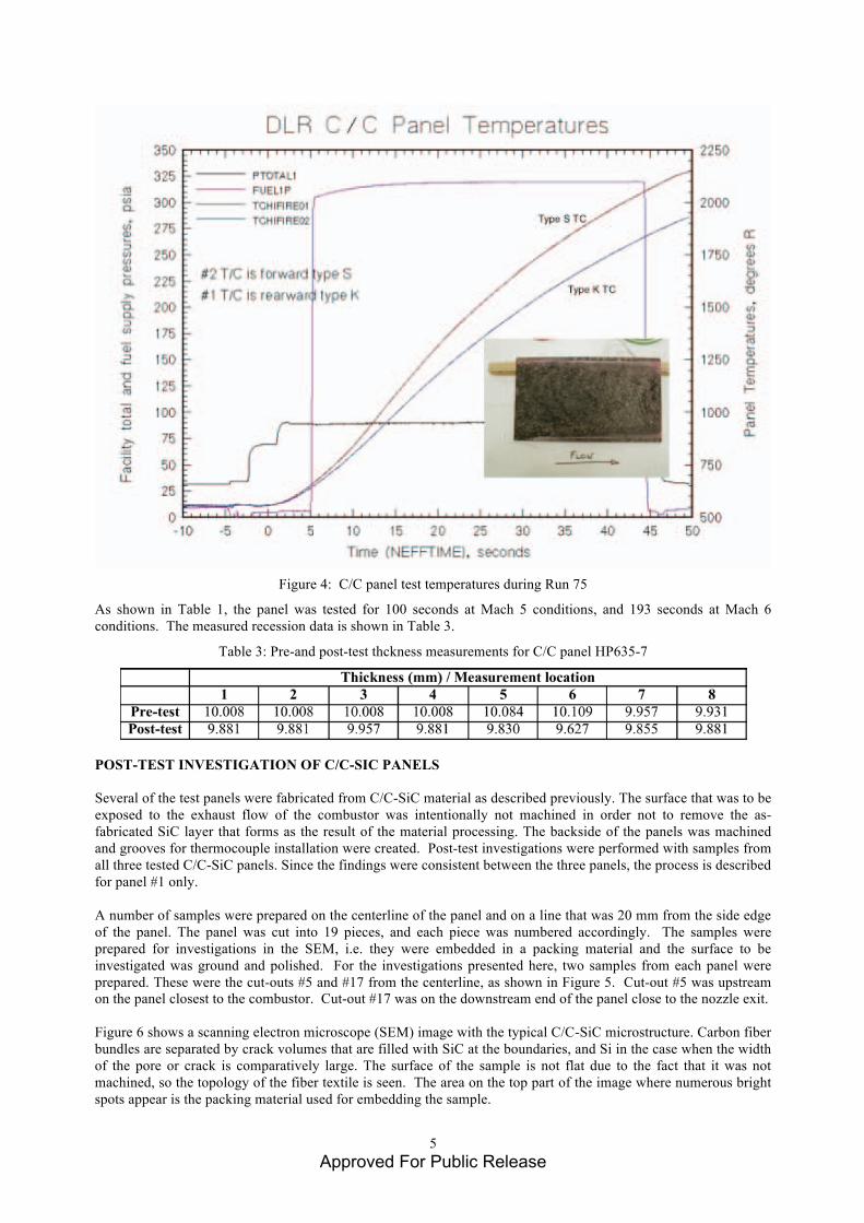
Figure 4: C/C panel test temperatures during Run 75
As shown in Table 1, the panel was tested for 100 seconds at Mach 5 conditions, and 193 seconds at Mach 6 conditions. The measured recession data is shown in Table 3.
Table 3: Pre-and post-test thckness measurements for C/C panel HP635-7
POST-TEST INVESTIGATION OF C/C-SIC PANELS Several of the test panels were fabricated from C/C-SiC material as described previously. The surface that was to be exposed to the exhaust flow of the combustor was intentionally not machined in order not to remove the as-fabricated SiC layer that forms as the result of the material processing. The backside of the panels was machined and grooves for thermocouple installation were created. Post-test investigations were performed with samples from all three tested C/C-SiC panels. Since the findings were consistent between the three panels, the process is described for panel #1 only. A number of samples were prepared on the centerline of the panel and on a line that was 20 mm from the side edge of the panel. The panel was cut into 19 pieces, and each piece was numbered accordingly. The samples were prepared for investigations in the SEM, i.e. they were embedded in a packing material and the surface to be investigated was ground and polished. For the investigations presented here, two samples from each panel were prepared. These were the cut-outs #5 and #17 from the centerline, as shown in Figure 5. Cut-out #5 was upstream on the panel closest to the combustor. Cut-out #17 was on the downstream end of the panel close to the nozzle exit. Figure 6 shows a scanning electron microscope (SEM) image with the typical C/C-SiC microstructure. Carbon fiber bundles are separated by crack volumes that are filled with SiC at the boundaries, and Si in the case when the width of the pore or crack is comparatively large. The surface of the sample is not flat due to the fact that it was not machined, so the topology of the fiber textile is seen. The area on the top part of the image where numerous bright spots appear is the packing material used for embedding the sample.

6 Approved For Public Release
There is no evidence of significant oxidation which might have resulted in degraded fibers or matrix near the surface. What can be seen is a thin bright layer on the surface that was identified as silicon dioxide (or silica) using electron diffraction spectroscopy (EDX) analysis.
Figure 5: Panel 1 with cut pattern for the sample preparation
Figure 6: SEM image of sample #5 from panel 1. There is a thin layer on the surface that is identified as silica. The
circle indicates the area that is shown in higher magnification in Figure 7. The close-up of the detail highlighted in Figure 6 is shown in Figure 7. The different material phases can be distinguished very well. There is a fiber bundle with silicon carbide on the surface. On the surface, above the silicon carbide is a thin layer of silica of around 20 µm thickness. The SiO2 layer on the surface does not have a constant thickness in every location over the sample. There are some spots where no SiO2 layer can be found and there are locations with a thinner layer compared to Figure 7, but in general, there is a SiO2 layer over most of the sample.
�
#5 �
#11 �
#17
�
#3 �
#9 �
#15

7 Approved For Public Release
Figure 7: SEM image of the SiO2 scale on top surface of the sample
Figure 8: SEM overview image of sample #17 from panel 1, exposed surface is on the top
Figure 9: Close-up SEM image showing some indication of matrix oxidation in the pore.
Figure 8 shows the surface of sample #17 from the end of the panel. There are a few cracks and pores in the two topmost layers. These could be the result of oxidation of the carbon since close-up images show signs of oxidation
Silicon carbide
Silicon dioxide, SiO2
Carbon fibers and carbon matrix
8 Approved For Public Release
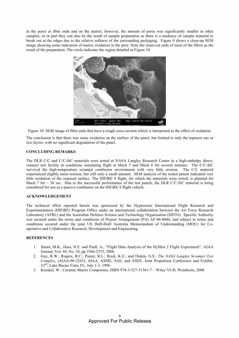
in the pores at fiber ends and on the matrix; however, the amount of pores was significantly smaller in other samples, so in part they can also be the result of sample preparation as there is a tendency of sample material to break out at the edges due to the relative softness of the surrounding packaging. Figure 9 shows a close-up SEM image showing some indication of matrix oxidation in the pore. Note the clean-cut ends of most of the fibers as the result of the preparation. The circle indicates the region detailed in Figure 10.
Figure 10: SEM image of fiber ends that have a rough cross-section which is interpreted as the effect of oxidation.
The conclusion is that there was some oxidation on the surface of the panel, but limited to only the topmost one or two layers, with no significant degradation of the panel. CONCLUDING REMARKS The DLR C/C and C/C-SiC materials were tested at NASA Langley Research Center in a high-enthalpy direct-connect test facility at conditions simulating flight at Mach 5 and Mach 6 for several minutes. The C/C-SiC survived the high-temperature scramjet combustor environment with very little erosion. The C/C material experienced slightly more erosion, but still only a small amount. SEM analysis of the tested panels indicated very little oxidation of the exposed surface. The HIFiRE 8 flight, for which the materials were tested, is planned for Mach 7 for ~ 30 sec. Due to the successful performance of the test panels, the DLR C/C-SiC material is being considered for use as a passive combustor on the HIFiRE 8 flight vehicle. ACKNOWLEDGEMENT The technical effort reported herein was sponsored by the Hypersonic International Flight Research and Experimentation (HIFiRE) Program Office under an international collaboration between the Air Force Research Laboratory (AFRL) and the Australian Defence Science and Technology Organisation (DSTO). Specific Authority was secured under the terms and conditions of Project Arrangement (PA) AF-06-0046, and subject to terms and conditions secured under the joint US DoD-DoD Australia Memorandum of Understanding (MOU) for Co-operative and Collaborative Research, Development and Engineering. REFERENCES
1. Smart, M.K., Hass, N.E. and Paull, A., “Flight Data Analysis of the HyShot 2 Flight Experiment”, AIAA Journal, Vol. 44, No. 10, pp 2366-2375, 2006.
2. Guy, R.W.; Rogers, R.C.; Puster, R.L.; Rock, K.E.; and Diskin, G.S.: The NASA Langley Scramjet Test Complex, (AIAA-96-3243), AIAA, ASME, SAE, and ASEE, Joint Propulsion Conference and Exhibit, 32nd, Lake Buena Vista, FL, July 1-3, 1996.
3. Krenkel, W.: Ceramic Matrix Composites, ISBN 978-3-527-31361-7 – Wiley-VCH, Weinheim, 2008