tests performed on hydraulic turbines at commis- sioning ...anale-ing.uem.ro/2015/19.pdf · tests...
TRANSCRIPT

175
Adrian Cuzmoş, Constantin-Viorel Câmpian, Doina Frunzăverde, Cosmin Dumbravă, Ana-Maria Budai
Tests Performed on Hydraulic Turbines at Commis-sioning or after Capital Repairs. Part I. Tests Per-formed on a 78-MW Francis Turbine
The paper presents the tests recommended by the standards to be per-formed on a hydraulic turbine on commissioning, after repair works or refurbishment, and the manner in which these tests were executed in a hydro power plant equipped with a 75-MW Francis turbine and the re-sults obtained.
Keywords: tests on the hydro units commissioning, index tests, Fran-cis turbine, power ejects, turbine commissioning
1. Introduction
As the need for electric energy keeps increasing, one is laying more and more stress on obtaining it from recoverable and environment-friendly sources. The elec-tric power obtained in hydro power plants falls within this category, and the own-ers of hydro power plants focus more and more on its efficient exploitation. As the costs of hydroelectric setups are high, most owners of hydro power plants decided to invest in the refurbishment , modernization and efficiency enhancement of the existing ones and their safe exploitation.
Before putting a new or refurbished hydro unit into industrial exploitation, it is subjected to a set of tests meant to verify that it operates at the designed parame-ters in conditions of safe exploitation. The paper purpose is to present the manner of performing the tests and the results obtained when determining the perform-ances of a hydro unit equipped with a Francis turbine, after the capital repair works, by the CCHAPT laboratory from „Eftimie Murgu” University of Resita. The results which will be presented may be used for comparison with other hydro units similar from the hydraulic point of view or with data originated from numerical simulations and also as model for other laboratories. In particular, on this hydro unit one performed also tests for determining the minimum and maximums exploi-
ANALELE UNIVERSIT ĂŢII
“EFTIMIE MURGU” RE ŞIŢA
ANUL XXII, NR. 1, 2015, ISSN 1453 - 7397

176
tation power, as between commissioning and capital repair works it functioned with a 70-MW power limitation, because of its failure to reach the prescribed levels in the storage accumulation on commissioning.
The technical characteristics of the hydro unit subjected to tests are the fol-lowing:
- Number of units from the hydro power plant: 2 - Type of unit: Francis Turbine - Entry rotor diameter: D1e = 2.6 m - Nominal number of revolutions: n = 428.6 rpm - Maximum net head: Hmax = 350 m - Maximum power at maximum head: Pmax = 78 MW - Net head: Hc = 326 m - Maximum power at net head: Pmax = 78 MW - Minimum net head: Hmin = 250 m - Maximum power at minimum head: P = 48.5 MW
2. Acceptance tests on hydraulic turbines
The acceptance tests on hydraulic turbines on commissioning or after capital repair or refurbishment works are regulated on the global level by standards.
Obviously, the type and number of tests eventually depend on beneficiaries and tests performers. They may be performed in totality, according to standards [1] or may be reduced or extend in type and number.
On the acceptance of a hydro unit or after capital repairs or refurbishment, [1] recommends the following types of tests:
- Idle tests; - Load tests; - Power ejects tests The load tests and power ejects tests generally aim at: - Checking the hydro unit power (comparison with the guarantees); - Certifying stability in operation, of cavitation and vibrations within the
range guaranteed by the supplier; - Checking the mode of operation of the adjustment parts and governor; - Determining the sudden variations of pressure and number of revolutions; - Determining and adjusting the types of closures of the wicket gate in or-
der to reduce the group over-revolution number. The dimensions recommended [1] to be measured and recorded during the
tests are the following: - Upstream and downstream level (or pressures); - Power at the generator’s terminals; - Opening and closing times for the adjustment parts; - Oil pressure in the adjustment system; - Vibrations.

177
3. Testes performed, measuring values, measuring instru-
ments, computed values
3.1. Tests performed
The beneficiary and the constructor, together with the tests performer, estab-lished the performance of the following tests:
- Establishment of the maximum and minimum power of the hydro unit op-eration;
- power eject from the maximum power with the verification of the wicket gate types of closure, verification of vibrations in bearings, verification of maximum number of revolutions in the over-raced regime, verification of pressures in the servomotor of the wicket gate, verification of the pressure in the penstock;
- Efficiency tests (index tests). 3.2. Measured values and measuring instruments
In order to record the values of the measured parameters one used measur-ing transducers connected to a data acquisition system. The measuring equipment belongs in totality to the tests performer, and when measuring and acquiring the monitored values one did not use beneficiary’s equipment.
The measured parameters and the sensors used for the acquisition of their values are presented in table 1.
Table 1. Measured parameters and the sensors Measured parameter Measuring instrument
Active power, currents and voltages at the generator’s terminals
VPA323 analyser of electrical parameters and process pa-
rameters
Head water level at the entry to the spiral chamber
GS4003 0 – 60 bar pressure transducer
Tail water level Rittmeyer level transducer MPB, 0 -10 m
Wicket gate servomotor stroke Temposonics shift transducer GP 0 – 1000 mm
Winter-Kennedy pressure gap Siemens SITRANS P 7MF4433-1DA02-1AA1-Z pressure gap transducer, 0 – 300 mBar

178
Pressure in the penstock GS4003 pressure transducer, 0 – 100 bar
Number of revolutions Banner QS30LDQ laser revolu-tion sensor, 0-120000 rpm
Vibrations Accelerometer Hansford Sen-sors, 533.3 mV/g
Pressure on one side of the piston of the wicket gate servomotor
GS4003 pressure transducer, 0- 40 bar
3.3. Computed values
For the performance tests (index tests) from the measured dimensions, previ-ously presented, one computed:
- The net head Hn [m]
γγei
ein
ppQzzH −+⋅⋅+−= − 23106099,7 (1)
where: zi is the head water level in the entry section to the spiral case; ze, tail wa-ter level in the exit section from the draft tube; Si, entry section to the turbine; Se, exit section from the turbine. - Index discharge Q [m3/s]
nWKi WKkQ ∆⋅= (2)
- The turbine power, PT [MW]
G
AhnT
PQHgP
ηηρ =⋅⋅⋅⋅= (3)
where PA – active power measured at the generator terminals; ηG – generator effi-ciency determined by the calorimetric method. The mechanical losses of the tur-bines were neglected.
- The turbine efficiency, ηT [%]
QHg
P
n
ThT ⋅⋅
==ρ
ηη (3)
As regards the procedure of index tests performance, they were executed in accordance with [2] and are presented in detail in [3].
4. The results
In order to determine the minimum power at which the unit can operate one decreased its power in sequences, permanently monitoring the parameters ac-quired and the noise level. The minimum power obtained was 33.07 MW. The op-
179
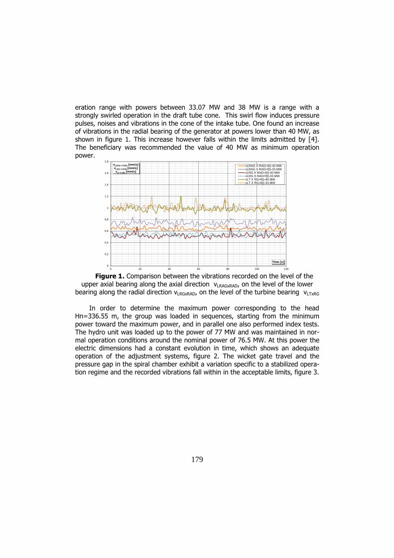
eration range with powers between 33.07 MW and 38 MW is a range with a strongly swirled operation in the draft tube cone. This swirl flow induces pressure pulses, noises and vibrations in the cone of the intake tube. One found an increase of vibrations in the radial bearing of the generator at powers lower than 40 MW, as shown in figure 1. This increase however falls within the limits admitted by [4]. The beneficiary was recommended the value of 40 MW as minimum operation power.
0
0,2
0,4
0,6
0,8
1
1,2
1,4
1,6
1,8
0 20 40 60 80 100 120
vLRAG X RAD [mm/s]vLRG X RAD [mm/s]vLT X RG [mm/s]
Time [s]
vLRAG X RAD=f(t)-40 MWvLRAG X RAD=f(t)-33 MWvLRG X RAD=f(t)-40 MWvLRG X RAD=f(t)-33 MWvLT X RG=f(t)-40 MWvLT X RG=f(t)-33 MW
Figure 1. Comparison between the vibrations recorded on the level of the
upper axial bearing along the axial direction vLRAGxRAD, on the level of the lower bearing along the radial direction vLRGxRAD, on the level of the turbine bearing vLTxRG
In order to determine the maximum power corresponding to the head
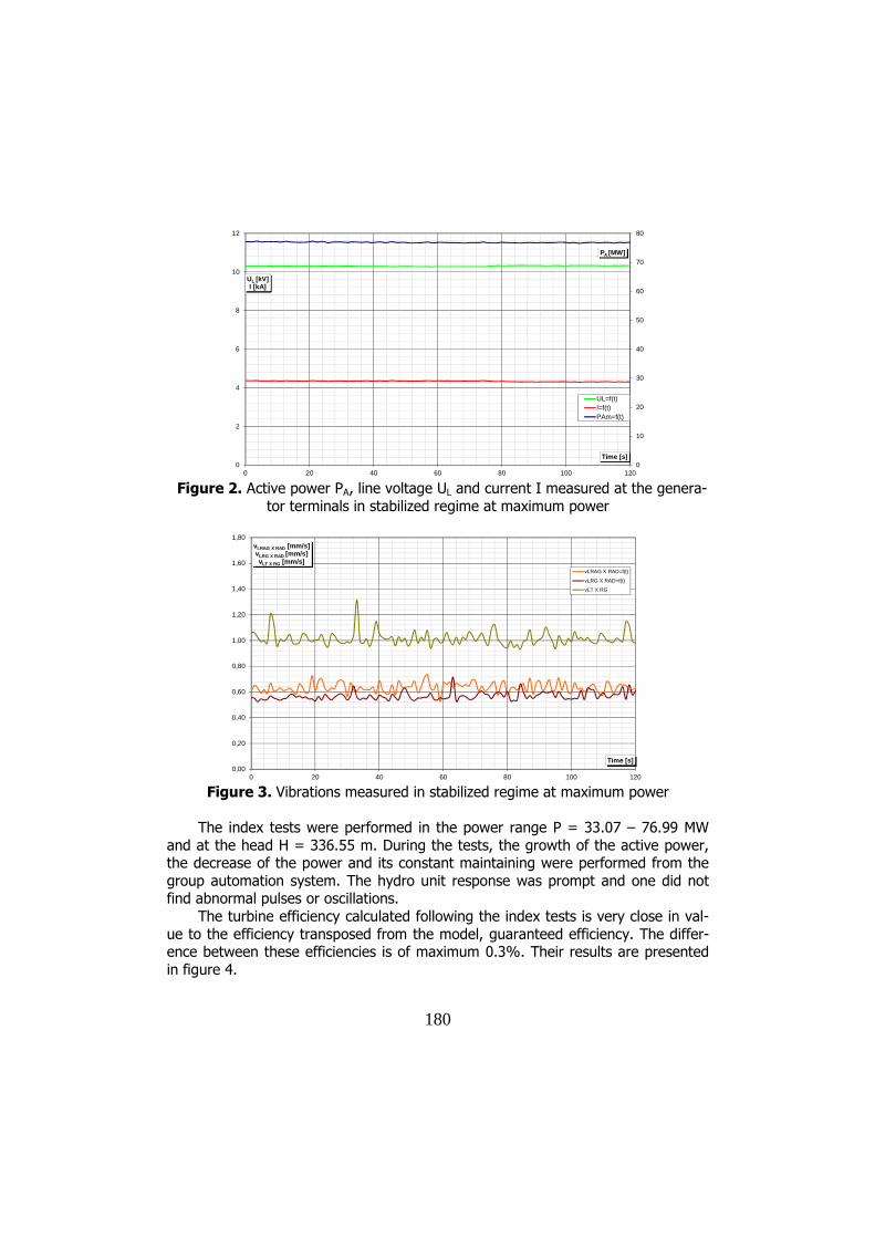
Hn=336.55 m, the group was loaded in sequences, starting from the minimum power toward the maximum power, and in parallel one also performed index tests. The hydro unit was loaded up to the power of 77 MW and was maintained in nor-mal operation conditions around the nominal power of 76.5 MW. At this power the electric dimensions had a constant evolution in time, which shows an adequate operation of the adjustment systems, figure 2. The wicket gate travel and the pressure gap in the spiral chamber exhibit a variation specific to a stabilized opera-tion regime and the recorded vibrations fall within in the acceptable limits, figure 3.
180
0
10
20
30
40
50
60
70
80
0
2
4
6
8
10
12
0 20 40 60 80 100 120
PA [MW]
UL [kV] I [kA]
Time [s]
UL=f(t)I=f(t)PAm=f(t)
Figure 2. Active power PA, line voltage UL and current I measured at the genera-
tor terminals in stabilized regime at maximum power
0,00
0,20
0,40
0,60
0,80
1,00
1,20
1,40
1,60
1,80
0 20 40 60 80 100 120
vLRAG X RAD [mm/s]vLRG X RAD [mm/s]vLT X RG [mm/s]
Time [s]
vLRAG X RAD=f(t)
vLRG X RAD=f(t)
vLT X RG
Figure 3. Vibrations measured in stabilized regime at maximum power
The index tests were performed in the power range P = 33.07 – 76.99 MW
and at the head H = 336.55 m. During the tests, the growth of the active power, the decrease of the power and its constant maintaining were performed from the group automation system. The hydro unit response was prompt and one did not find abnormal pulses or oscillations.
The turbine efficiency calculated following the index tests is very close in val-ue to the efficiency transposed from the model, guaranteed efficiency. The differ-ence between these efficiencies is of maximum 0.3%. Their results are presented in figure 4.

181
0
50
100
150
200
250
30
40
50
60
70
80
90
100
12 14 16 18 20 22 24 26
SAD [mm]ηT [%]PT [MW]PA [MW]
Q [m3/s]
Index tests turbine efficiencyScaled-up from model effciencyWicket gates servomotor strokeTurbine powerHydrounit power
Figure 4. Index tests results at 336,55 m head
The power eject test was performed from the 74 MW power, with the neigh-
boring hydro unit in operation. On the moment of the power eject test of hydro unit, by switching off the line interrupter, while the generator is connected to the network and operations at a certain active and reactive power, the turbine rotor is over-raced. The over-racing is a guaranteed dimension and is checked with the grantee tests for regulator.
The dimensions recorded and presented for this rotating regime were: vibra-tions along the +x direction in the axial radial upper bearing (LRAG) and lower ra-dial one (LRG) of the generator and turbine bearing (LT) (figure 5), time of wicket gate closure (figure 6), maximum racing rotative speed n (figure 7), maximum val-ue of pressure occurring in the penstock (figure 8).
Figure 4. Measured vibrations
0
1
2
3
4
5
6
0 10 20 30 40 50 60 70Timp[s]
v[mm/s]
LRAG_x_rad
LRG_x_rad
LT_x_rad
Time [s]

182
Figure 5. Wicket gate closure time
Figure 6. Maximum racing rotative speed n
420
440
460
480
500
520
540
560
580
600
0 2 4 6 8 10 12 14 16
Timp[s]
n[rpm] nmax=581[rpm]
Time [s]
0
10
20
30
40
50
60
70
80
90
100
110
120
130
140
150
160
170
180
190
200
210
220
230
240
250
0 1 2 3 4 5 6 7 8 9 10
Timp[s]
SAD[mm]
Time [s]

183
Figure 7. Maximum value of pressure occurring in the penstock pCF
Of the monitored dimensions, plotted in the previous graphs, one found that the maximum vibrations at power eject occurred on the level of the upper axial bearing of the generator, values reaching the value 4.85 mm/s compared to 0.620 mm/s during the load operation. The recorded wicket gate closing time is about 9 sec.
The maximum over-revolution of rotor at the power eject of the 74 MW hydro unit is 581 rpm which represents a 35.74% increased above the nominal number of revolutions, values lower than the maximum values provided in the technical documentation.
At the closure of the wicket gate, in the forced pipe the pressure grew up to 36.414 bar, 3.61 bar higher than the normal pressure. After the closure of the wicket gate, in the penstock a pressure wave occurs propagated in both directions, until it is completely attenuated, in around 1.5 hours. The maximum oscillation amplitude was 2.05 bar, and the period of the first oscillation is 372 sec.
5. Conclusion
The minimum recommended power at which the hydro unit may operate in optimum conditions is 40 MW, whereas the maximum power obtained for the fall H = 336.55 m is 76.5 MW, power at which it may operate without restrictions.
The turbine efficiency calculated from the index tests is very close to the value of the efficiently transposed from the model. The difference between these effi-ciencies is of maximum 0.3%.
At power ejects the values of the hydro unit over-revolution and over-pressures occurring in the penstock do not exceed safety values. One found a prompt response of the adjustment system.
32
33
34
35
36
37
0 200 400 600 800 1000 1200
Timp (s)
pCF[bar]
pCF max=36.414[bar]
Time [s]

184
Of the tests performed and results obtained one could conclude the following: the respective hydro unit may operate without restrictions at the power 76.5 MW and the head H = 336.55 m, it can be used in a secondary and primary adjustment in the power range 40 -76.5 MW, the level of vibrations recorded during the stabi-lised regime operation fell within the limits established by [4].
Acknowledgment
The work has been funded by the Sectoral Operational Programme Human Resources Development 2007-2013 of the Ministry of European Funds through the Financial Agreement POSDRU/159/1.5/S/132395.
References
[1] ***** Guide for the acceptance, exploitation and maintenance of hy-dro turbines, International Standard SR CEI 600545:2001, ASRO February 2001.
[2] ***** Field acceptance tests to determine the hydraulic performance of hydraulic turbines, storage pumps and bulb turbines. International Standard IEC 60041.
[3] Cuzmoş A., Brebu N., Câmpian C.V., Dumbravă C., Intex Tests Per-formed on Hydro Unit no2 from HPP Ruieni before and after Refurbish-ment, Annals of the University “Eftimie Murgu” of Reşiţa year XX, no. 1, 2013, page. 87 – 94.
[4] ***** Power units - Permissible vibrations - Specifications, Interna-tional Standard SR 6910:2012.
Addresses:
• Dr. Eng. Adrian Cuzmoş, “Eftimie Murgu” University of Reşiţa, Piaţa Traian Vuia, nr. 1-4, 320085, Reşiţa, [email protected]
• Prof. Dr. Eng. Constantin-Viorel Câmpian, “Eftimie Murgu” University of Reşiţa, Piaţa Traian Vuia, nr. 1-4, 320085, Reşiţa, [email protected]
• Prof. Dr. Eng. Doina Frunzăverde, “Eftimie Murgu” University of Reşiţa, Piaţa Traian Vuia, nr. 1-4, 320085, Reşiţa, [email protected]
• Eng. Cosmin Dumbravă, “Eftimie Murgu” University of Reşiţa, Piaţa Traian Vuia, nr. 1-4, 320085, Reşiţa, [email protected]
• Lect. Dr. Eng. Ana-Maria Budai, “Eftimie Murgu” University of Reşiţa, • Piaţa Traian Vuia, nr. 1-4, 320085, Reşiţa, [email protected]