tesys u dtm for fdt container - online help
TRANSCRIPT

TeSys U DTM for FDT Container
1672613 08/2013
167
2613
www.schneider-electric.com
TeSys U DTM for FDT ContainerOnline Help
08/2013
The information provided in this documentation contains general descriptions and/or technical character-istics of the performance of the products contained herein. This documentation is not intended as a substitute for and is not to be used for determining suitability or reliability of these products for specific user applications. It is the duty of any such user or integrator to perform the appropriate and complete risk analysis, evaluation and testing of the products with respect to the relevant specific application or use thereof. Neither Schneider Electric nor any of its affiliates or subsidiaries shall be responsible or liable for misuse of the information that is contained herein. If you have any suggestions for improvements or amendments or have found errors in this publication, please notify us.
No part of this document may be reproduced in any form or by any means, electronic or mechanical, including photocopying, without express written permission of Schneider Electric.
All pertinent state, regional, and local safety regulations must be observed when installing and using this product. For reasons of safety and to help ensure compliance with documented system data, only the manufacturer should perform repairs to components.
When devices are used for applications with technical safety requirements, the relevant instructions must be followed.
Failure to use Schneider Electric software or approved software with our hardware products may result in injury, harm, or improper operating results.
Failure to observe this information can result in injury or equipment damage.
© 2013 Schneider Electric. All rights reserved.
2 1672613 08/2013

Table of Contents
Safety Information . . . . . . . . . . . . . . . . . . . . . . . . . . . . . . . . . . . . . . . . . . . 5About the Book. . . . . . . . . . . . . . . . . . . . . . . . . . . . . . . . . . . . . . . . . . . . . . 7
Chapter 1 Presentation of the TeSys U DTM. . . . . . . . . . . . . . . . . . . . . . . . . . . . . . . 91.1 Introduction . . . . . . . . . . . . . . . . . . . . . . . . . . . . . . . . . . . . . . . . . . . . . . . . . . . . . . . . . . . . . . 10
Presentation of the TeSys U Starter-Controller . . . . . . . . . . . . . . . . . . . . . . . . . . . . . . . . . . . 11TeSys U Selection Guide . . . . . . . . . . . . . . . . . . . . . . . . . . . . . . . . . . . . . . . . . . . . . . . . . . . 16Definitions . . . . . . . . . . . . . . . . . . . . . . . . . . . . . . . . . . . . . . . . . . . . . . . . . . . . . . . . . . . . . . . 18Installing SoMove and the TeSys DTM Library . . . . . . . . . . . . . . . . . . . . . . . . . . . . . . . . . . . 19Installing Update TeSys DTM Library . . . . . . . . . . . . . . . . . . . . . . . . . . . . . . . . . . . . . . . . . . 20Hardware Connection for SoMove . . . . . . . . . . . . . . . . . . . . . . . . . . . . . . . . . . . . . . . . . . . . 21
1.2 User Interface . . . . . . . . . . . . . . . . . . . . . . . . . . . . . . . . . . . . . . . . . . . . . . . . . . . . . . . . . . . . 22General Description. . . . . . . . . . . . . . . . . . . . . . . . . . . . . . . . . . . . . . . . . . . . . . . . . . . . . . . . 23Menu Bar and Tool Bar . . . . . . . . . . . . . . . . . . . . . . . . . . . . . . . . . . . . . . . . . . . . . . . . . . . . . 25Status Bar and Synchronization Data Bar . . . . . . . . . . . . . . . . . . . . . . . . . . . . . . . . . . . . . . . 26my Device Tab . . . . . . . . . . . . . . . . . . . . . . . . . . . . . . . . . . . . . . . . . . . . . . . . . . . . . . . . . . . 29operate Tab . . . . . . . . . . . . . . . . . . . . . . . . . . . . . . . . . . . . . . . . . . . . . . . . . . . . . . . . . . . . . 30Tab Zone . . . . . . . . . . . . . . . . . . . . . . . . . . . . . . . . . . . . . . . . . . . . . . . . . . . . . . . . . . . . . . . . 32parameter list Tab . . . . . . . . . . . . . . . . . . . . . . . . . . . . . . . . . . . . . . . . . . . . . . . . . . . . . . . . 35fault Tab . . . . . . . . . . . . . . . . . . . . . . . . . . . . . . . . . . . . . . . . . . . . . . . . . . . . . . . . . . . . . . . . 37monitoring Tab. . . . . . . . . . . . . . . . . . . . . . . . . . . . . . . . . . . . . . . . . . . . . . . . . . . . . . . . . . . 38diagnostic Tab . . . . . . . . . . . . . . . . . . . . . . . . . . . . . . . . . . . . . . . . . . . . . . . . . . . . . . . . . . . 40
Chapter 2 Metering and Monitoring Functions . . . . . . . . . . . . . . . . . . . . . . . . . . . . . 412.1 Measurement. . . . . . . . . . . . . . . . . . . . . . . . . . . . . . . . . . . . . . . . . . . . . . . . . . . . . . . . . . . . . 42
Line Currents . . . . . . . . . . . . . . . . . . . . . . . . . . . . . . . . . . . . . . . . . . . . . . . . . . . . . . . . . . . . . 43Ground Current . . . . . . . . . . . . . . . . . . . . . . . . . . . . . . . . . . . . . . . . . . . . . . . . . . . . . . . . . . . 44Average Current . . . . . . . . . . . . . . . . . . . . . . . . . . . . . . . . . . . . . . . . . . . . . . . . . . . . . . . . . . 45Current Phase Imbalance . . . . . . . . . . . . . . . . . . . . . . . . . . . . . . . . . . . . . . . . . . . . . . . . . . . 46Thermal Capacity Level. . . . . . . . . . . . . . . . . . . . . . . . . . . . . . . . . . . . . . . . . . . . . . . . . . . . . 47Minimum Wait Time. . . . . . . . . . . . . . . . . . . . . . . . . . . . . . . . . . . . . . . . . . . . . . . . . . . . . . . . 48
2.2 Device Monitoring Faults . . . . . . . . . . . . . . . . . . . . . . . . . . . . . . . . . . . . . . . . . . . . . . . . . . . . 49TeSys U Internal Faults . . . . . . . . . . . . . . . . . . . . . . . . . . . . . . . . . . . . . . . . . . . . . . . . . . . . . 50LUCM Internal Temperature . . . . . . . . . . . . . . . . . . . . . . . . . . . . . . . . . . . . . . . . . . . . . . . . . 51Wiring Faults . . . . . . . . . . . . . . . . . . . . . . . . . . . . . . . . . . . . . . . . . . . . . . . . . . . . . . . . . . . . . 52Communication Loss . . . . . . . . . . . . . . . . . . . . . . . . . . . . . . . . . . . . . . . . . . . . . . . . . . . . . . . 53Shunt Fault Command. . . . . . . . . . . . . . . . . . . . . . . . . . . . . . . . . . . . . . . . . . . . . . . . . . . . . . 55
2.3 Statistics . . . . . . . . . . . . . . . . . . . . . . . . . . . . . . . . . . . . . . . . . . . . . . . . . . . . . . . . . . . . . . . . 56Fault and Warning Counters . . . . . . . . . . . . . . . . . . . . . . . . . . . . . . . . . . . . . . . . . . . . . . . . . 57Fault History . . . . . . . . . . . . . . . . . . . . . . . . . . . . . . . . . . . . . . . . . . . . . . . . . . . . . . . . . . . . . 58Motor Statistics . . . . . . . . . . . . . . . . . . . . . . . . . . . . . . . . . . . . . . . . . . . . . . . . . . . . . . . . . . . 59
Chapter 3 Motor Protection Functions. . . . . . . . . . . . . . . . . . . . . . . . . . . . . . . . . . . . 61Motor Protection Characteristics . . . . . . . . . . . . . . . . . . . . . . . . . . . . . . . . . . . . . . . . . . . . . . 62FLA (Full Load Amps) Settings . . . . . . . . . . . . . . . . . . . . . . . . . . . . . . . . . . . . . . . . . . . . . . . 63Thermal Overload . . . . . . . . . . . . . . . . . . . . . . . . . . . . . . . . . . . . . . . . . . . . . . . . . . . . . . . . . 64Short-Circuit. . . . . . . . . . . . . . . . . . . . . . . . . . . . . . . . . . . . . . . . . . . . . . . . . . . . . . . . . . . . . . 67Magnetic . . . . . . . . . . . . . . . . . . . . . . . . . . . . . . . . . . . . . . . . . . . . . . . . . . . . . . . . . . . . . . . . 68Ground Current . . . . . . . . . . . . . . . . . . . . . . . . . . . . . . . . . . . . . . . . . . . . . . . . . . . . . . . . . . . 69Current Phase Imbalance . . . . . . . . . . . . . . . . . . . . . . . . . . . . . . . . . . . . . . . . . . . . . . . . . . . 71Long Start . . . . . . . . . . . . . . . . . . . . . . . . . . . . . . . . . . . . . . . . . . . . . . . . . . . . . . . . . . . . . . . 74Jam . . . . . . . . . . . . . . . . . . . . . . . . . . . . . . . . . . . . . . . . . . . . . . . . . . . . . . . . . . . . . . . . . . . . 76Undercurrent . . . . . . . . . . . . . . . . . . . . . . . . . . . . . . . . . . . . . . . . . . . . . . . . . . . . . . . . . . . . . 78
1672613 08/2013 3
Chapter 4 Motor Control Functions . . . . . . . . . . . . . . . . . . . . . . . . . . . . . . . . . . . . . . 81Operating States . . . . . . . . . . . . . . . . . . . . . . . . . . . . . . . . . . . . . . . . . . . . . . . . . . . . . . . . . . 82Start Cycle . . . . . . . . . . . . . . . . . . . . . . . . . . . . . . . . . . . . . . . . . . . . . . . . . . . . . . . . . . . . . . . 84Logic Output Assignment . . . . . . . . . . . . . . . . . . . . . . . . . . . . . . . . . . . . . . . . . . . . . . . . . . . . 85Recovery Mode . . . . . . . . . . . . . . . . . . . . . . . . . . . . . . . . . . . . . . . . . . . . . . . . . . . . . . . . . . . 87Reflex Stop Functions . . . . . . . . . . . . . . . . . . . . . . . . . . . . . . . . . . . . . . . . . . . . . . . . . . . . . . 88Warning Management . . . . . . . . . . . . . . . . . . . . . . . . . . . . . . . . . . . . . . . . . . . . . . . . . . . . . . 90Detected Fault Management . . . . . . . . . . . . . . . . . . . . . . . . . . . . . . . . . . . . . . . . . . . . . . . . . 91Clear Commands . . . . . . . . . . . . . . . . . . . . . . . . . . . . . . . . . . . . . . . . . . . . . . . . . . . . . . . . . . 94
Chapter 5 Communication Functions . . . . . . . . . . . . . . . . . . . . . . . . . . . . . . . . . . . . 95Configuration of the LULC•• Network Port . . . . . . . . . . . . . . . . . . . . . . . . . . . . . . . . . . . . . . . 96Configuration of the Tesys U LUCM HMI Port . . . . . . . . . . . . . . . . . . . . . . . . . . . . . . . . . . . . 98
Index . . . . . . . . . . . . . . . . . . . . . . . . . . . . . . . . . . . . . . . . . . . . . . . . . . . . . . 99
4 1672613 08/2013
Safety Information
Important Information
NOTICE
Read these instructions carefully, and look at the equipment to become familiar with the device before trying to install, operate, or maintain it. The following special messages may appear throughout this documentation or on the equipment to warn of potential hazards or to call attention to information that clarifies or simplifies a procedure.
PLEASE NOTE
Electrical equipment should be installed, operated, serviced, and maintained only by qualified personnel. No responsibility is assumed by Schneider Electric for any consequences arising out of the use of this material.
A qualified person is one who has skills and knowledge related to the construction and operation of electrical equipment and its installation, and has received safety training to recognize and avoid the hazards involved.
1672613 08/2013 5

6 1672613 08/2013
About the Book
At a Glance
Document Scope
This online help describes: the TeSys U DTM for TeSys U starter-controllers up to 15 kW (20 hp) the metering and monitoring, protection, and control functions of the TeSys U starter-controllers
This online help is intended for Tesys U DTM users: design engineers system integrators system operators maintenance engineers
Validity Note
This document has been updated with the release of SoMove Lite V1.6.1.1 and TeSys DTM library 2.7.4.0.
The availability of some functions depends on the TeSys U starter-controller version.
Related Documents
You can download these technical publications and other technical information from our website at www.schneider-electric.com.
Title of Documentation Reference Number
TeSys® U LUCM/LUCMT Multifunction Control Units - User’s Manual 1743237
TeSys® U Communication Variables - User’s Manual 1744082
TeSys® U LULC032-LULC033 Modbus Module - User’s Manual 1743234
TeSys® U LULC07 Profibus DP Module - User’s Manual 1672610
TeSys® U LULC08 CANopen Module - User’s Manual 1744084
TeSys® U LULC09 DeviceNet Module - User’s Manual 1744085
TeSys® U LULC15 Advantys STB Module - User’s Manual 1744083
1672613 08/2013 7

8 1672613 08/2013
TeSys U DTM for FDT Container
Presentation of the TeSys U DTM
1672613 08/2013
Presentation of the TeSys U DTM
Chapter 1Presentation of the TeSys U DTM
What Is in This Chapter?
This chapter contains the following sections:
Section Topic Page
1.1 Introduction 10
1.2 User Interface 22
1672613 08/2013 9

Presentation of the TeSys U DTM
Introduction
Section 1.1Introduction
Overview
This section describes the prerequisites for using the TeSys U starter-controller and companion devices with SoMove and the TeSys U DTM.
What Is in This Section?
This section contains the following topics:
Topic Page
Presentation of the TeSys U Starter-Controller 11
TeSys U Selection Guide 16
Definitions 18
Installing SoMove and the TeSys DTM Library 19
Installing Update TeSys DTM Library 20
Hardware Connection for SoMove 21
10 1672613 08/2013
Presentation of the TeSys U DTM
Presentation of the TeSys U Starter-Controller
Overview
The TeSys U starter-controller is a Direct On Line starter for use with inductive loads (control of DC or capacitive loads is not possible). The TeSys U starter-controller performs the following functions: Protection and control of single-phase or 3-phase motors: isolation and breaking function overload and short-circuit protection thermal overload protection power switching
Control of the application: protection function alarms, application monitoring (running time, number of faults, motor current
values, etc.) logs (last 5 faults saved, together with motor parameter values)
These functions can be added by selecting control units and function modules which simply clip into the power base. This customization is possible after power and control circuit wiring has been completed.
TeSys U is a flexible range that meets the current and future needs of system builders, panel builders and machine manufacturers, as well as those of additional systems.
From design through to operation, TeSys U offers many advantages and simplifies the selection of components in comparison with a traditional solution: The breaking, isolation and contactor functions are incorporated in a single block; this means fewer
references to be ordered and easy selection without any risk of error, because a single reference covers all needs up to 15 kW (20 hp).
The control unit has a wide setting range. It can operate on a DC or AC supply.
The number of references required is divided by 10, compared with traditional solutions.
The compact components in the TeSys U range are mounted on a single rail, in order to optimizing the amount of space required in enclosures. By eliminating power wiring between the circuit-breaker and contactor, TeSys U reduces installation times in enclosures.
Setting-up accessories simplify or completely eliminate wiring between components and decrease the risk of errors.
1672613 08/2013 11

Presentation of the TeSys U DTM
TeSys U Starter-Controller
A TeSys U starter-controller consists of a power base and a control unit.
1 Power base LUB12 or LUB32 with embedded non-removable auxiliary contact block2 Power base LUB120 or LUB320 without auxiliary contacts3 Control unit LUC•••4 Optional auxiliary contact block LU9BN11, LU9BN11C or LU9BN11L
Power Base
The power base is independent of the control voltage.
It is available from 0 to 15 kW (20 hp) at 400 Vac.
It incorporates the breaking function with a breaking capacity of 50 kA at 400 Vac, total coordination (continuity of service) and the switching function.
2 ratings are available: 0…12 A 0…32 A
It can be non-reversing (LUB) and reversing (LU2B).
2 types of power bases are available: LUB12 and LUB32 power bases with embedded non-removable auxiliary contact block (1 NO + 1 NC). LUB120 and LUB320 power bases without auxiliary contact block. The following optional auxiliary
contact blocks should be added to the power bases: LU9BN11: coil control + 1 NO + 1 NC LU9BN11C: direct link to LUFC00, LULC033 or ASILUFC51 modules for coil control + 1 NO + 1 NC LU9BN11L: direct link to LULC07, LULC08, LULC09, or LULC15 modules for coil control + 1 NO +
1 NC
12 1672613 08/2013

Presentation of the TeSys U DTM
Control Unit
The control unit must be selected according to the control voltage, the power of the motor to be protected and the type of protection required.
To obtain the comprehensive control unit reference number, the generic characters •• must be replaced by the relevant reference code. Refer to the TeSys U starter-controllers catalogue.
The control units are interchangeable without rewiring and without using tools.
They have a wide range of adjustment (range of 4) and low heat dissipation, because bimetallic overload protection components are no longer used.
Control Unit Functional Description Reference
StandardThermal magnetic protection
Satisfies the basic protection requirements for motor starters: protection against overloads and short-circuits protection against phase failure and phase imbalance earth fault protection (equipment protection only) manual reset
LUCA••
StandardMagnetic protection
When fitted upstream of a variable speed drive or soft start-soft stop unit and used in conjunction with an LUB12, LUB32, LUB120, or LUB320 power base, this unit provides isolation and short-circuit protection of the motor starter: protection against short-circuits manual reset
LUCL••
Advanced Allows additional advanced functions such as alarm, fault differentiation: same functions as the standard control unit in addition, in conjunction with a function module: fault differentiation with manual reset fault differentiation with remote or automatic reset thermal overload alarm indication of motor load
LUCB••, LUCC•• or LUCD••
Multifunction Suitable for the most sophisticated control and protection requirements: same functions as the standard control unit in addition, reset parameters can be set to manual or automatic protection function alarm indication on front panel or on remote terminal via Modbus RS 485 port log function monitoring function, indication of main motor parameters on front panel of
the control unit, or via a remote terminal differentiation of thermal overload and magnetic fault overload, no-load running
LUCM••
1672613 08/2013 13
Presentation of the TeSys U DTM
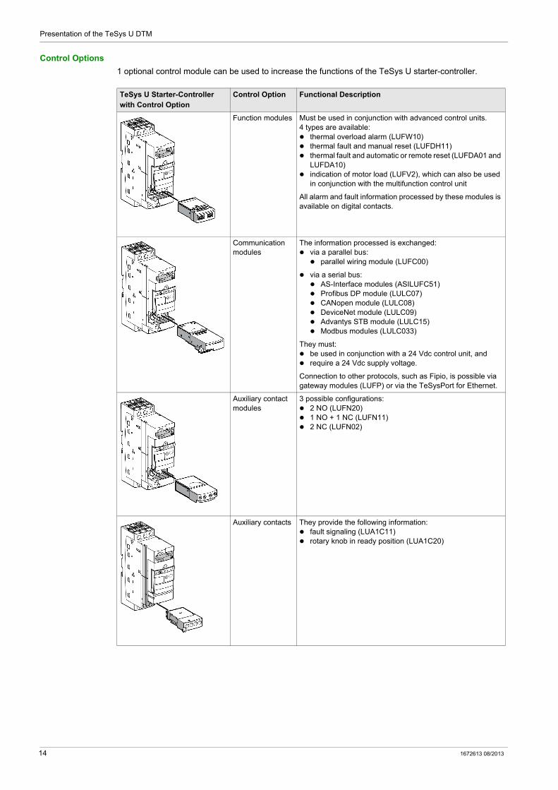
Control Options
1 optional control module can be used to increase the functions of the TeSys U starter-controller.
TeSys U Starter-Controller with Control Option
Control Option Functional Description
Function modules Must be used in conjunction with advanced control units.4 types are available: thermal overload alarm (LUFW10) thermal fault and manual reset (LUFDH11) thermal fault and automatic or remote reset (LUFDA01 and
LUFDA10) indication of motor load (LUFV2), which can also be used
in conjunction with the multifunction control unit
All alarm and fault information processed by these modules is available on digital contacts.
Communication modules
The information processed is exchanged: via a parallel bus: parallel wiring module (LUFC00)
via a serial bus: AS-Interface modules (ASILUFC51) Profibus DP module (LULC07) CANopen module (LULC08) DeviceNet module (LULC09) Advantys STB module (LULC15) Modbus modules (LULC033)
They must: be used in conjunction with a 24 Vdc control unit, and require a 24 Vdc supply voltage.
Connection to other protocols, such as Fipio, is possible via gateway modules (LUFP) or via the TeSysPort for Ethernet.
Auxiliary contact modules
3 possible configurations: 2 NO (LUFN20) 1 NO + 1 NC (LUFN11) 2 NC (LUFN02)
Auxiliary contacts They provide the following information: fault signaling (LUA1C11) rotary knob in ready position (LUA1C20)
14 1672613 08/2013

Presentation of the TeSys U DTM
Power Options
TeSys U Starter-Controller with Power Option
Power Option Functional Description
Reverser block Allows a non-reversing power base to be converted to reversing operation: The reverser block LU2M is mounted directly
beneath the power base without modifying the width of the product (45 mm or 1.77 in.),
The reverser block LU6M is mounted separately from the power base when the height available is limited.
Limiter-disconnector The unit (LUALB) is mounted directly on the power base. It allows the breaking capacity to be increased up to 130 kA at 400 Vac, with a visible break.
1672613 08/2013 15
Presentation of the TeSys U DTM
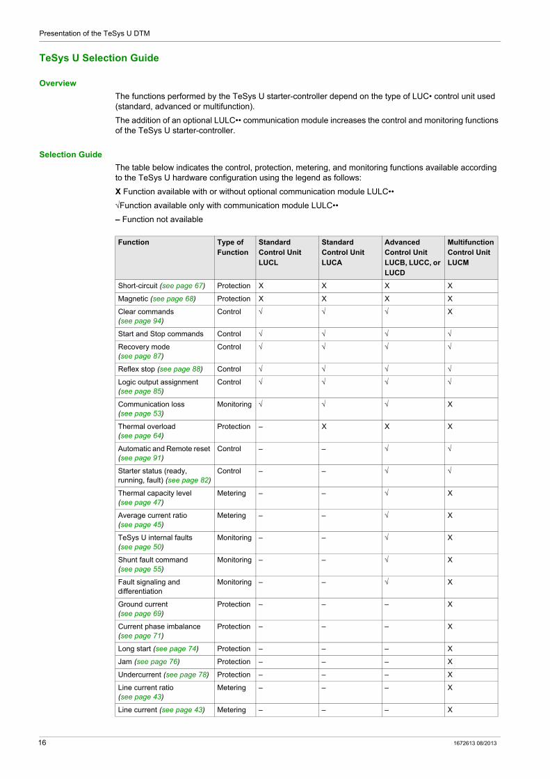
TeSys U Selection Guide
Overview
The functions performed by the TeSys U starter-controller depend on the type of LUC• control unit used (standard, advanced or multifunction).
The addition of an optional LULC•• communication module increases the control and monitoring functions of the TeSys U starter-controller.
Selection Guide
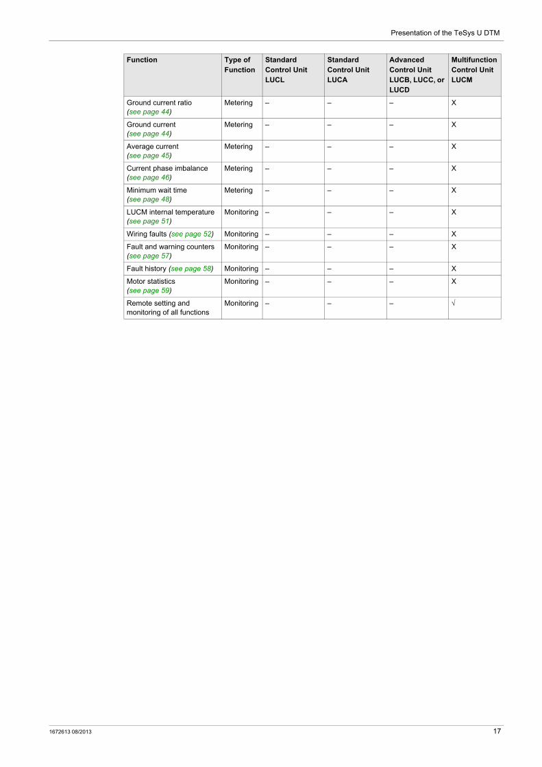
The table below indicates the control, protection, metering, and monitoring functions available according to the TeSys U hardware configuration using the legend as follows:
X Function available with or without optional communication module LULC••
√ Function available only with communication module LULC••
– Function not available
Function Type of Function
Standard Control Unit LUCL
Standard Control Unit LUCA
Advanced Control Unit LUCB, LUCC, or LUCD
Multifunction Control Unit LUCM
Short-circuit (see page 67) Protection X X X X
Magnetic (see page 68) Protection X X X X
Clear commands (see page 94)
Control √ √ √ X
Start and Stop commands Control √ √ √ √
Recovery mode (see page 87)
Control √ √ √ √
Reflex stop (see page 88) Control √ √ √ √
Logic output assignment (see page 85)
Control √ √ √ √
Communication loss (see page 53)
Monitoring √ √ √ X
Thermal overload (see page 64)
Protection – X X X
Automatic and Remote reset (see page 91)
Control – – √ √
Starter status (ready, running, fault) (see page 82)
Control – – √ √
Thermal capacity level (see page 47)
Metering – – √ X
Average current ratio (see page 45)
Metering – – √ X
TeSys U internal faults (see page 50)
Monitoring – – √ X
Shunt fault command (see page 55)
Monitoring – – √ X
Fault signaling and differentiation
Monitoring – – √ X
Ground current (see page 69)
Protection – – – X
Current phase imbalance (see page 71)
Protection – – – X
Long start (see page 74) Protection – – – X
Jam (see page 76) Protection – – – X
Undercurrent (see page 78) Protection – – – X
Line current ratio (see page 43)
Metering – – – X
Line current (see page 43) Metering – – – X
16 1672613 08/2013
Presentation of the TeSys U DTM
Ground current ratio (see page 44)
Metering – – – X
Ground current (see page 44)
Metering – – – X
Average current (see page 45)
Metering – – – X
Current phase imbalance (see page 46)
Metering – – – X
Minimum wait time (see page 48)
Metering – – – X
LUCM internal temperature (see page 51)
Monitoring – – – X
Wiring faults (see page 52) Monitoring – – – X
Fault and warning counters (see page 57)
Monitoring – – – X
Fault history (see page 58) Monitoring – – – X
Motor statistics (see page 59)
Monitoring – – – X
Remote setting and monitoring of all functions
Monitoring – – – √
Function Type of Function
Standard Control Unit LUCL
Standard Control Unit LUCA
Advanced Control Unit LUCB, LUCC, or LUCD
Multifunction Control Unit LUCM
1672613 08/2013 17
Presentation of the TeSys U DTM
Definitions
FDT (Field Device Tool)
FDT technology: standardizes the communication and configuration interface between all field devices and host systems provides a common environment for accessing the devices features
For more information about FDT technology, refer to the following website: http://www.fdtgroup.org/index.php
FDT Container
The FDT container is software that uses the FDT technology. It is used to: install a DTM library to add new devices modify an already installed DTM library to update existing devices
DTM (Device Type Manager)
The DTM is a software module installed in an FDT container for a specific device. It provides a unified structure for: accessing device parameters configuring and operating the devices diagnosing problems
The TeSys T or TeSys U DTM can be in extended mode or in basic mode, depending on the FDT container used: The extended mode is only available with SoMove, and gives access to all functions of the DTM. The basic mode is available with other compatible FDT containers, and gives access to certain functions
of the DTM.
DTM Library
A DTM library is a set of DTMs that works with an FDT container.
The TeSys DTM library includes: TeSys T DTM TeSys U DTM
SoMove Project File
A SoMove project file is a configuration file for a pre-determined device, that can be created offline and saved for later use.
A project file contains the following information: device type selected characteristics, such as firmware version all parameters settings
NOTE:
The project file does not contain the customized program. This file is saved with the extension *.psx.
For more information on how to create a project, see the SoMove Lite online help.
18 1672613 08/2013
Presentation of the TeSys U DTM
Installing SoMove and the TeSys DTM Library
Overview
The installation of SoMove includes some DTMs such as the TeSys DTM library.
The TeSys DTM library includes: TeSys T DTM TeSys U DTM
These DTM are automatically installed during the SoMove installation process.
Downloading SoMove
SoMove can be downloaded from the Schneider Electric website (www.schneider-electric.com) by entering SoMove Lite in the Search field.
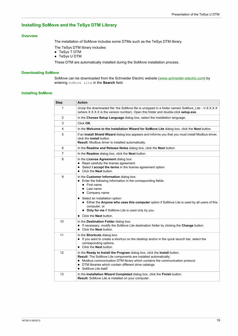
Installing SoMove
Step Action
1 Unzip the downloaded file: the SoMove file is unzipped in a folder named SoMove_Lite - V.X.X.X.X (where X.X.X.X is the version number). Open this folder and double-click setup.exe.
2 In the Choose Setup Language dialog box, select the installation language.
3 Click OK.
4 In the Welcome to the Installation Wizard for SoMove Lite dialog box, click the Next button.
5 If an Install Shield Wizard dialog box appears and informs you that you must install Modbus driver, click the Install button. Result: Modbus driver is installed automatically.
6 In the Readme and Release Notes dialog box, click the Next button.
7 In the Readme dialog box, click the Next button.
8 In the License Agreement dialog box: Read carefully the license agreement. Select I accept the terms in the license agreement option. Click the Next button.
9 In the Customer Information dialog box: Enter the following information in the corresponding fields: First name Last name Company name
Select an installation option: Either the Anyone who uses this computer option if SoMove Lite is used by all users of this
computer, or Only for me if SoMove Lite is used only by you.
Click the Next button.
10 In the Destination Folder dialog box: If necessary, modify the SoMove Lite destination folder by clicking the Change button. Click the Next button.
11 In the Shortcuts dialog box: If you want to create a shortcut on the desktop and/or in the quick launch bar, select the
corresponding options. Click the Next button.
12 In the Ready to Install the Program dialog box, click the Install button.Result: The SoMove Lite components are installed automatically: Modbus communication DTM library which contains the communication protocol DTM libraries which contain different drive catalogs SoMove Lite itself
13 In the Installation Wizard Completed dialog box, click the Finish button.Result: SoMove Lite is installed on your computer.
1672613 08/2013 19
Presentation of the TeSys U DTM
Installing Update TeSys DTM Library
Overview
The TeSys DTM library includes: TeSys T DTM TeSys U DTM
These DTM are automatically installed during the SoMove installation process.
Downloading TeSysDTMLibrary
TeSysDTMLibrary can be downloaded from the Schneider Electric website (www.schneider-electric.com) by entering TeSysDTMLibrary in the Search field.
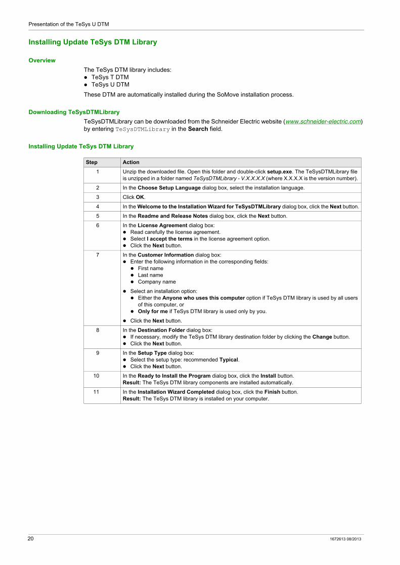
Installing Update TeSys DTM Library
Step Action
1 Unzip the downloaded file. Open this folder and double-click setup.exe. The TeSysDTMLibrary file is unzipped in a folder named TeSysDTMLibrary - V.X.X.X.X (where X.X.X.X is the version number).
2 In the Choose Setup Language dialog box, select the installation language.
3 Click OK.
4 In the Welcome to the Installation Wizard for TeSysDTMLibrary dialog box, click the Next button.
5 In the Readme and Release Notes dialog box, click the Next button.
6 In the License Agreement dialog box: Read carefully the license agreement. Select I accept the terms in the license agreement option. Click the Next button.
7 In the Customer Information dialog box: Enter the following information in the corresponding fields: First name Last name Company name
Select an installation option: Either the Anyone who uses this computer option if TeSys DTM library is used by all users
of this computer, or Only for me if TeSys DTM library is used only by you.
Click the Next button.
8 In the Destination Folder dialog box: If necessary, modify the TeSys DTM library destination folder by clicking the Change button. Click the Next button.
9 In the Setup Type dialog box: Select the setup type: recommended Typical. Click the Next button.
10 In the Ready to Install the Program dialog box, click the Install button.Result: The TeSys DTM library components are installed automatically.
11 In the Installation Wizard Completed dialog box, click the Finish button.Result: The TeSys DTM library is installed on your computer.
20 1672613 08/2013
Presentation of the TeSys U DTM
Hardware Connection for SoMove
Overview
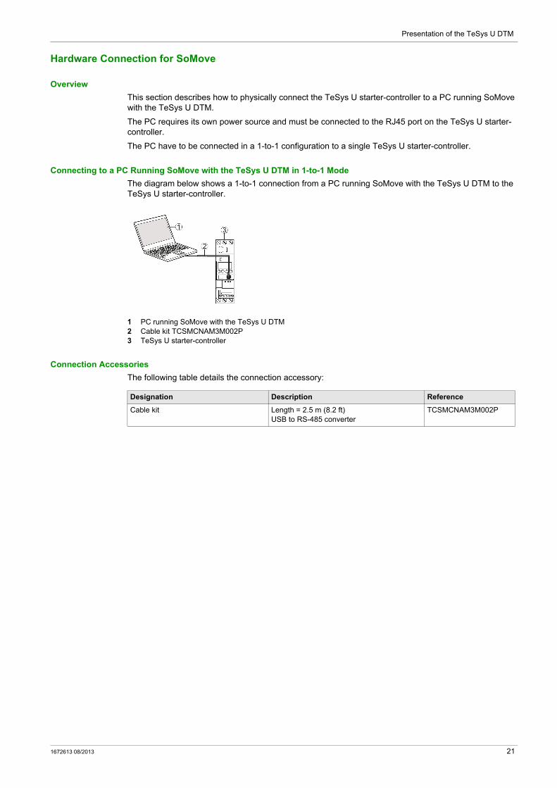
This section describes how to physically connect the TeSys U starter-controller to a PC running SoMove with the TeSys U DTM.
The PC requires its own power source and must be connected to the RJ45 port on the TeSys U starter-controller.
The PC have to be connected in a 1-to-1 configuration to a single TeSys U starter-controller.
Connecting to a PC Running SoMove with the TeSys U DTM in 1-to-1 Mode
The diagram below shows a 1-to-1 connection from a PC running SoMove with the TeSys U DTM to the TeSys U starter-controller.
1 PC running SoMove with the TeSys U DTM2 Cable kit TCSMCNAM3M002P3 TeSys U starter-controller
Connection Accessories
The following table details the connection accessory:
Designation Description Reference
Cable kit Length = 2.5 m (8.2 ft)USB to RS-485 converter
TCSMCNAM3M002P
1672613 08/2013 21
Presentation of the TeSys U DTM
User Interface
Section 1.2User Interface
Overview
This section describes the different menus and tabs available in SoMove with the TeSys U DTM.
What Is in This Section?
This section contains the following topics:
Topic Page
General Description 23
Menu Bar and Tool Bar 25
Status Bar and Synchronization Data Bar 26
my Device Tab 29
operate Tab 30
Tab Zone 32
parameter list Tab 35
fault Tab 37
monitoring Tab 38
diagnostic Tab 40
22 1672613 08/2013

Presentation of the TeSys U DTM
General Description
Overview
The TeSys U DTM can be in extended mode or in basic mode, depending on the FDT container used: The extended mode is only available with SoMove, and gives access to all functions of the DTM. The basic mode is available with other compatible FDT containers, and gives access to certain functions
of the DTM.
Extended Mode Presentation
The working space is divided into the following zones:1 menu bar (see page 25)2 tool bar (see page 25)3 synchronization data area (see page 26)4 status bar (see page 26)5 tab zone (content depending on the selected tab)
1672613 08/2013 23
Presentation of the TeSys U DTM
Basic Mode Presentation
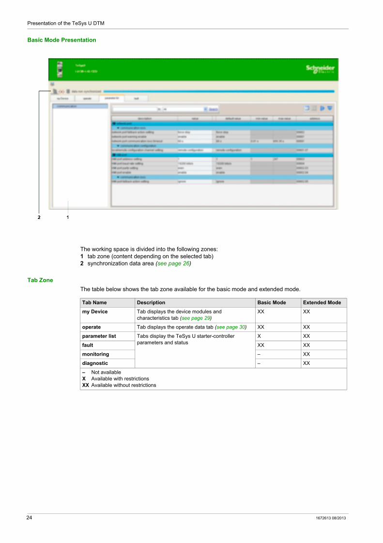
The working space is divided into the following zones:1 tab zone (content depending on the selected tab)2 synchronization data area (see page 26)
Tab Zone
The table below shows the tab zone available for the basic mode and extended mode.
Tab Name Description Basic Mode Extended Mode
my Device Tab displays the device modules and characteristics tab (see page 29)
XX XX
operate Tab displays the operate data tab (see page 30) XX XX
parameter list Tabs display the TeSys U starter-controller parameters and status
X XX
fault XX XX
monitoring – XX
diagnostic – XX
– Not availableX Available with restrictionsXX Available without restrictions
24 1672613 08/2013

Presentation of the TeSys U DTM
Menu Bar and Tool Bar
Menu Bar
These functions are available with the extended mode using SoMove. The menu bar, at the top of the working space, is represented below:
Only the functions specific to the TeSys U starter-controller are described here: Device menu that contains the TeSys U DTM specific functions (available in connected mode only). File menu where the SoMove Configuration Recovery function is adapted to the TeSys U DTM.
Other menus are generic and are described in the SoMove Lite online help.
Tool Bar
The tool bar, at the top of the working space directly beneath the menu bar, is specific to the DTM:
The buttons of the tool bar enable the user to directly access the main functions without using the menu bar.
The tool bar Refresh button is used to refresh all parameters from the connected TeSys U starter-controller.
Device Menu in the Connected Mode
Configuration Recovery
The Configuration Recovery function allows loading a PowerSuite 2 project file using the TeSys U DTM in SoMove.
NOTE: Missing information in the PowerSuite 2 project file can be completed during the recovery process if some parameters cannot be retrieved from the PowerSuite 2 project file.
More details about this function can be found in the SoMove Lite online help.
Submenu Function Description
Reset (see page 91)
fault reset Resets detected faults
clear (see page 94)
clear all Erases all parameters (history, statistics, network, etc.) except the LUCM internal temperature max parameters
clear statistics Erases statistics except the LUCM internal temperature max parameters
clear Th capa level Erases thermal information to bypass a thermal fault for emergency restart (see page 64)
Maintenance Th overload test Simulates a thermal fault
shunt Simulates a short-circuit (see page 55)
Step Action
1 Click File → Open.
2 In the file type selection list, select PS2 Configuration Files.
3 Open the PowerSuite 2 project file .ub2 to recover.
1672613 08/2013 25
Presentation of the TeSys U DTM
Status Bar and Synchronization Data Bar
Objective
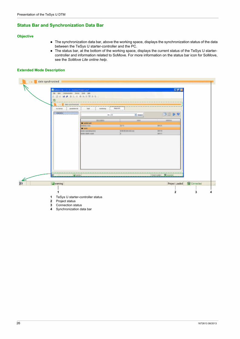
The synchronization data bar, above the working space, displays the synchronization status of the data between the TeSys U starter-controller and the PC.
The status bar, at the bottom of the working space, displays the current status of the TeSys U starter-controller and information related to SoMove. For more information on the status bar icon for SoMove, see the SoMove Lite online help.
Extended Mode Description
1 TeSys U starter-controller status2 Project status3 Connection status4 Synchronization data bar
26 1672613 08/2013
Presentation of the TeSys U DTM
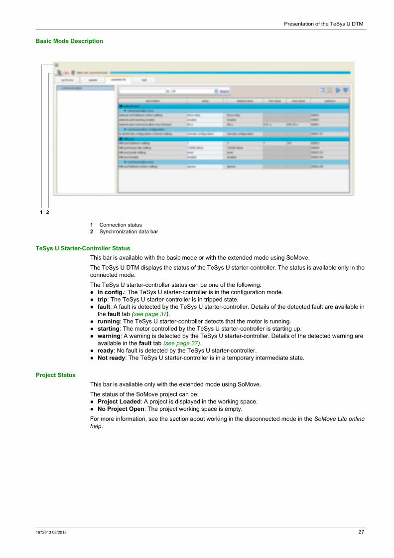
Basic Mode Description
1 Connection status2 Synchronization data bar
TeSys U Starter-Controller Status
This bar is available with the basic mode or with the extended mode using SoMove.
The TeSys U DTM displays the status of the TeSys U starter-controller. The status is available only in the connected mode.
The TeSys U starter-controller status can be one of the following: in config.: The TeSys U starter-controller is in the configuration mode. trip: The TeSys U starter-controller is in tripped state. fault: A fault is detected by the TeSys U starter-controller. Details of the detected fault are available in
the fault tab (see page 37). running: The TeSys U starter-controller detects that the motor is running. starting: The motor controlled by the TeSys U starter-controller is starting up. warning: A warning is detected by the TeSys U starter-controller. Details of the detected warning are
available in the fault tab (see page 37). ready: No fault is detected by the TeSys U starter-controller. Not ready: The TeSys U starter-controller is in a temporary intermediate state.
Project Status
This bar is available only with the extended mode using SoMove.
The status of the SoMove project can be: Project Loaded: A project is displayed in the working space. No Project Open: The project working space is empty.
For more information, see the section about working in the disconnected mode in the SoMove Lite online help.
1672613 08/2013 27
Presentation of the TeSys U DTM
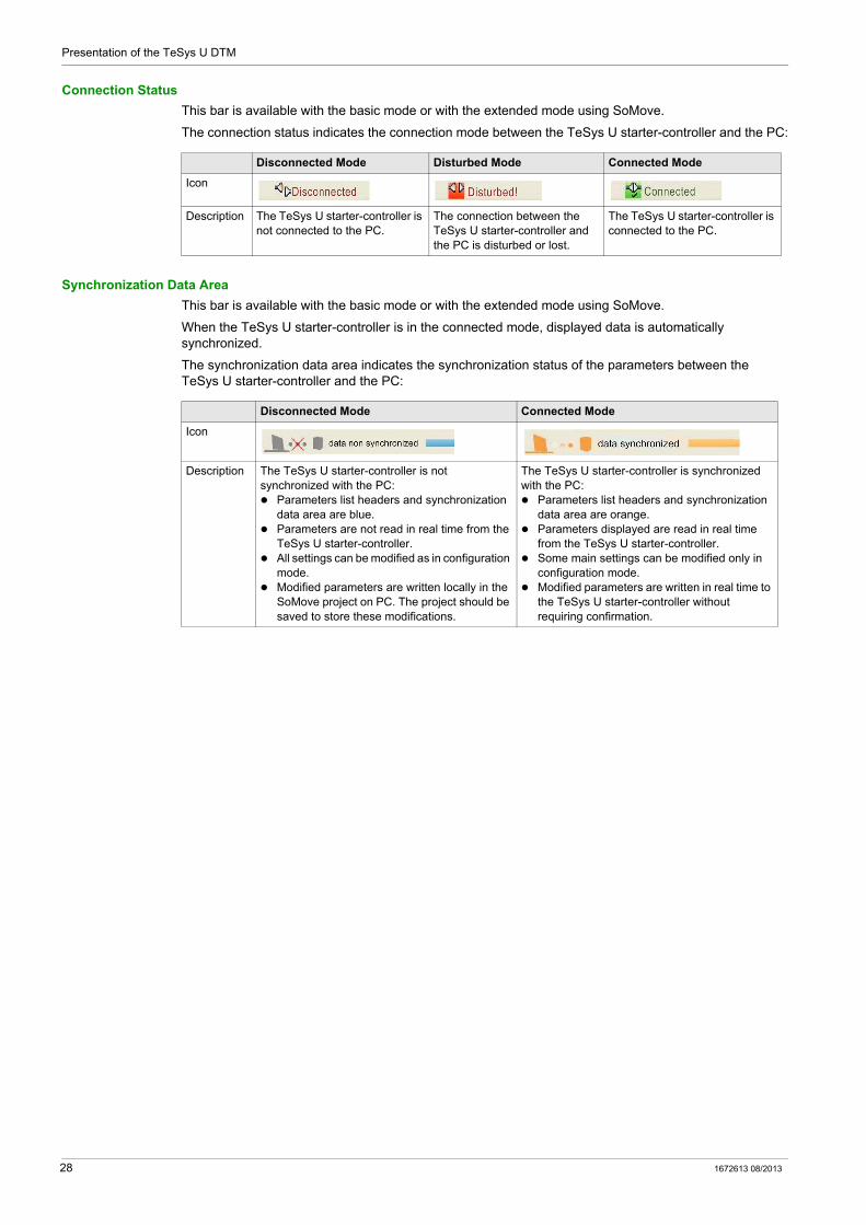
Connection Status
This bar is available with the basic mode or with the extended mode using SoMove.
The connection status indicates the connection mode between the TeSys U starter-controller and the PC:
Synchronization Data Area
This bar is available with the basic mode or with the extended mode using SoMove.
When the TeSys U starter-controller is in the connected mode, displayed data is automatically synchronized.
The synchronization data area indicates the synchronization status of the parameters between the TeSys U starter-controller and the PC:
Disconnected Mode Disturbed Mode Connected Mode
Icon
Description The TeSys U starter-controller is not connected to the PC.
The connection between the TeSys U starter-controller and the PC is disturbed or lost.
The TeSys U starter-controller is connected to the PC.
Disconnected Mode Connected Mode
Icon
Description The TeSys U starter-controller is not synchronized with the PC: Parameters list headers and synchronization
data area are blue. Parameters are not read in real time from the
TeSys U starter-controller. All settings can be modified as in configuration
mode. Modified parameters are written locally in the
SoMove project on PC. The project should be saved to store these modifications.
The TeSys U starter-controller is synchronized with the PC: Parameters list headers and synchronization
data area are orange. Parameters displayed are read in real time
from the TeSys U starter-controller. Some main settings can be modified only in
configuration mode. Modified parameters are written in real time to
the TeSys U starter-controller without requiring confirmation.
28 1672613 08/2013

Presentation of the TeSys U DTM
my Device Tab
Overview
This tab is available with the basic mode or with the extended mode using SoMove.
The my Device tab displays the main characteristics and modules of the selected TeSys U starter-controller.
Description
This figure presents the informations about the TeSys U starter-controller.
Information Displayed
The my Device tab displays the following information about the TeSys U starter-controller: characteristics: the TeSys U starter-controller base type the TeSys U starter-controller control unit type the current rating in Amperes the motor phases number the motor class the network port protocol
structure of the TeSys U starter-controller: reference number of each module firmware version of each module
software: version of the TeSys U DTM
visual elements: A picture represents the TeSys U starter-controller corresponding to the selected type.
1672613 08/2013 29
Presentation of the TeSys U DTM
operate Tab
Overview
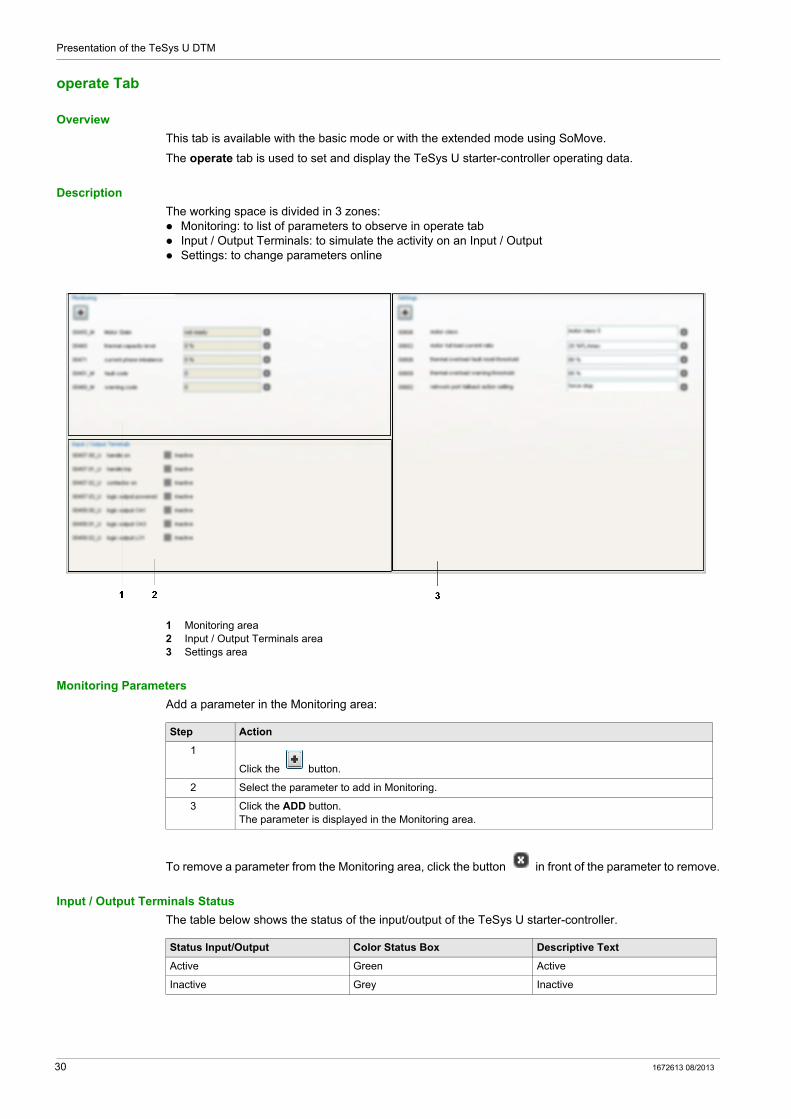
This tab is available with the basic mode or with the extended mode using SoMove.
The operate tab is used to set and display the TeSys U starter-controller operating data.
Description
The working space is divided in 3 zones: Monitoring: to list of parameters to observe in operate tab Input / Output Terminals: to simulate the activity on an Input / Output Settings: to change parameters online
1 Monitoring area2 Input / Output Terminals area3 Settings area
Monitoring Parameters
Add a parameter in the Monitoring area:
To remove a parameter from the Monitoring area, click the button in front of the parameter to remove.
Input / Output Terminals Status
The table below shows the status of the input/output of the TeSys U starter-controller.
Step Action
1
Click the button.
2 Select the parameter to add in Monitoring.
3 Click the ADD button.The parameter is displayed in the Monitoring area.
Status Input/Output Color Status Box Descriptive Text
Active Green Active
Inactive Grey Inactive
30 1672613 08/2013
Presentation of the TeSys U DTM
Settings Parameters
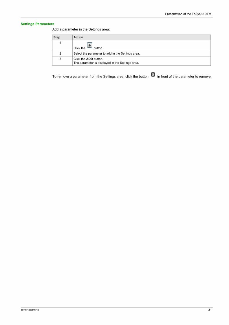
Add a parameter in the Settings area:
To remove a parameter from the Settings area, click the button in front of the parameter to remove.
Step Action
1
Click the button.
2 Select the parameter to add in the Settings area.
3 Click the ADD button.The parameter is displayed in the Settings area.
1672613 08/2013 31

Presentation of the TeSys U DTM
Tab Zone
Overview
The following tabs display information in the same way.
Description
This figure presents the common information in these tabs:
1 Tree view with items and subitems used to access to different tables of parameters.
2 Display area with the table of parameters corresponding to the selected item or subitem in the tree view.
3 Search function.
4 Display area tool bar.
Tab Name Description Basic Mode Extended Mode
parameter list Tabs display the TeSys U starter-controller parameters and status
X XX
fault XX XX
monitoring – XX
diagnostic – XX
This topic presents the different parts of the screen and their function.
– Not availableX Available with restrictionsXX Available without restrictions
32 1672613 08/2013

Presentation of the TeSys U DTM
Tree View
The tree view is composed of items with or without subitems. Select an item or subitem in the tree to update the display area on the right. The displayed table includes the corresponding parameters grouped in families and subfamilies.
Display Area Tool Bar
The view of the display area can be modified using the following buttons available on the top right corner of the display area:
Display Area in Grid View
1 Column header.
2 Parameter family.
3 Parameter subfamily.
4 Parameters: There is one line per parameter. Content of white cells can be modified, gray cells are read-only.
5 Collapse/Expand icon: to collapse or expand a parameter family or subfamily, click the arrow of the corresponding colored line.
Button Function Description
Grid view Parameters are listed by family and subfamily in a table.
Sketch view Parameters are presented with diagrams (charts, drawings, etc.) to explain parameters settings in a user-friendly way. Currently, TeSys U DTM does not provide such a view.
Expand All Expand all families and subfamilies to display all parameters.
Collapse All Collapse all families and subfamilies in the display area.
1672613 08/2013 33
Presentation of the TeSys U DTM
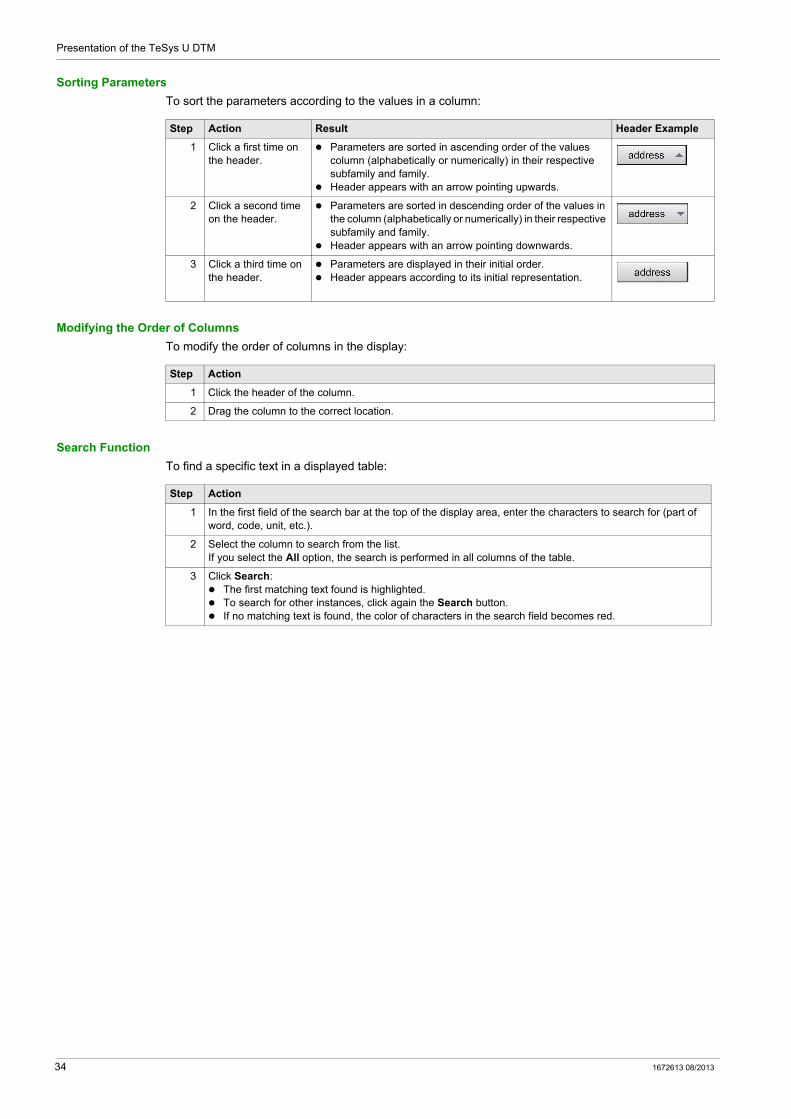
Sorting Parameters
To sort the parameters according to the values in a column:
Modifying the Order of Columns
To modify the order of columns in the display:
Search Function
To find a specific text in a displayed table:
Step Action Result Header Example
1 Click a first time on the header.
Parameters are sorted in ascending order of the values column (alphabetically or numerically) in their respective subfamily and family.
Header appears with an arrow pointing upwards.
2 Click a second time on the header.
Parameters are sorted in descending order of the values in the column (alphabetically or numerically) in their respective subfamily and family.
Header appears with an arrow pointing downwards.
3 Click a third time on the header.
Parameters are displayed in their initial order. Header appears according to its initial representation.
Step Action
1 Click the header of the column.
2 Drag the column to the correct location.
Step Action
1 In the first field of the search bar at the top of the display area, enter the characters to search for (part of word, code, unit, etc.).
2 Select the column to search from the list.If you select the All option, the search is performed in all columns of the table.
3 Click Search: The first matching text found is highlighted. To search for other instances, click again the Search button. If no matching text is found, the color of characters in the search field becomes red.
34 1672613 08/2013
Presentation of the TeSys U DTM
parameter list Tab
Overview
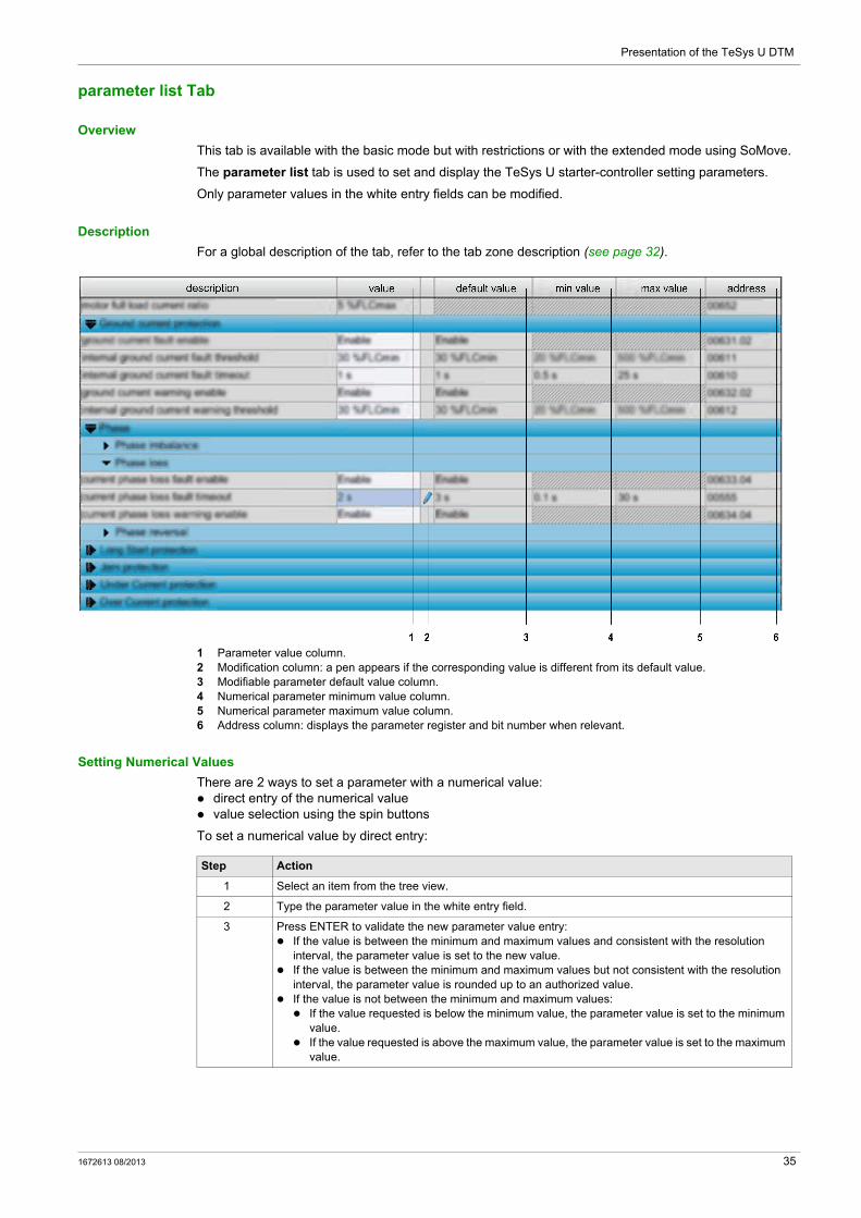
This tab is available with the basic mode but with restrictions or with the extended mode using SoMove.
The parameter list tab is used to set and display the TeSys U starter-controller setting parameters.
Only parameter values in the white entry fields can be modified.
Description
For a global description of the tab, refer to the tab zone description (see page 32).
1 Parameter value column.2 Modification column: a pen appears if the corresponding value is different from its default value.3 Modifiable parameter default value column.4 Numerical parameter minimum value column.5 Numerical parameter maximum value column.6 Address column: displays the parameter register and bit number when relevant.
Setting Numerical Values
There are 2 ways to set a parameter with a numerical value: direct entry of the numerical value value selection using the spin buttons
To set a numerical value by direct entry:
Step Action
1 Select an item from the tree view.
2 Type the parameter value in the white entry field.
3 Press ENTER to validate the new parameter value entry: If the value is between the minimum and maximum values and consistent with the resolution
interval, the parameter value is set to the new value. If the value is between the minimum and maximum values but not consistent with the resolution
interval, the parameter value is rounded up to an authorized value. If the value is not between the minimum and maximum values: If the value requested is below the minimum value, the parameter value is set to the minimum
value. If the value requested is above the maximum value, the parameter value is set to the maximum
value.
1672613 08/2013 35
Presentation of the TeSys U DTM
To set a numerical value with the spin buttons:
Editing a String
To set a string parameter:
Selecting Values in a List
To select a value in a list:
Step Action
1 Select an item from the tree view.
2 Click in the white entry field of the parameter to set it with the spin buttons that are displayed on the right of the entry field.
3 Increase or decrease the value with the spin buttons. You cannot increase the value above the maximum authorized value, or decrease it below the minimum authorized value.
Step Action
1 Select an item from the tree view.
2 Type the string in the white entry field.
3 Press ENTER to validate.
Step Action
1 Select an item from the tree view.
2 Click in the white entry field of the parameter to set it with the down arrow button that is displayed on the right of the entry field.
3 Click the arrow button to open the drop-down selection list.
4 Select a value.
5 Press ENTER to validate the selection.
36 1672613 08/2013

Presentation of the TeSys U DTM
fault Tab
Overview
This tab is available with the basic mode or with the extended mode using SoMove.
The fault tab displays the detected faults or warnings related to the connected TeSys U starter-controller (see page 49).
The data in this tab is only significant in the connected mode.
Description
For a global description of the tab, refer to the tab zone description (see page 32).
This tab displays: the status of detected faults and warnings in the TeSys U starter-controller: the fault and warning statuses the fault and warning counters (see page 57)
a history of the detected faults (see page 58)
Status Item in Tree View
The table in the display area shows the faults and warnings that can be detected by the TeSys U starter-controller. In the connected mode, it displays in real time the status of the faults and warnings detected by the connected TeSys U starter-controller.
The different columns provide the following information:
Fault History Item in Tree View
The TeSys U starter-controller stores the history of the 5 last detected faults. Each record contains monitoring data when the fault occurred, this helps investigation about the fault cause. Fault N-0 contains the most recent fault record, and fault N-4 contains the oldest retained fault record.
For each detected fault, the following information is displayed: the detected fault code and its description date and time of fault detection value of important settings when the fault occurred value of measurements recorded when the fault was detected (see page 58)
Column Information
description Name of the detected fault or warning.
fault Detected fault status:
: A red light indicates that the cause of the detected fault is not resolved.
: A grayed out light indicates that there is no detected fault. When a fault detection is disabled, no light is displayed in the corresponding cell.
fault count Amount of detected faults since the last clear all or clear statistics action.
warning Detected warning status:
: An orange light indicates that the cause of the detected warning is not resolved.
: A grayed out light indicates that there is no detected warning. When a warning detection is disabled, no light is displayed in the corresponding cell.
warning count Amount of detected warnings since the last clear all or clear statistics action.
1672613 08/2013 37
Presentation of the TeSys U DTM
monitoring Tab
Overview
This tab is available with the extended mode using SoMove.
The monitoring tab is used to monitor in real time the status and measurements of the connected TeSys U starter-controller.
The data in this tab are only significant in the connected mode.
Description
For a global description of the tab, refer to the tab zone description (see page 32).
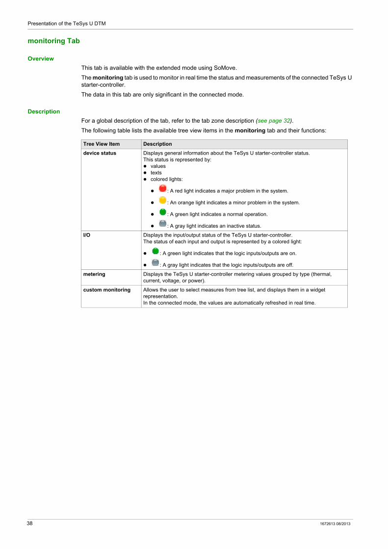
The following table lists the available tree view items in the monitoring tab and their functions:
Tree View Item Description
device status Displays general information about the TeSys U starter-controller status.This status is represented by: values texts colored lights:
: A red light indicates a major problem in the system.
: An orange light indicates a minor problem in the system.
: A green light indicates a normal operation.
: A gray light indicates an inactive status.
I/O Displays the input/output status of the TeSys U starter-controller.The status of each input and output is represented by a colored light:
: A green light indicates that the logic inputs/outputs are on.
: A gray light indicates that the logic inputs/outputs are off.
metering Displays the TeSys U starter-controller metering values grouped by type (thermal, current, voltage, or power).
custom monitoring Allows the user to select measures from tree list, and displays them in a widget representation.In the connected mode, the values are automatically refreshed in real time.
38 1672613 08/2013
Presentation of the TeSys U DTM
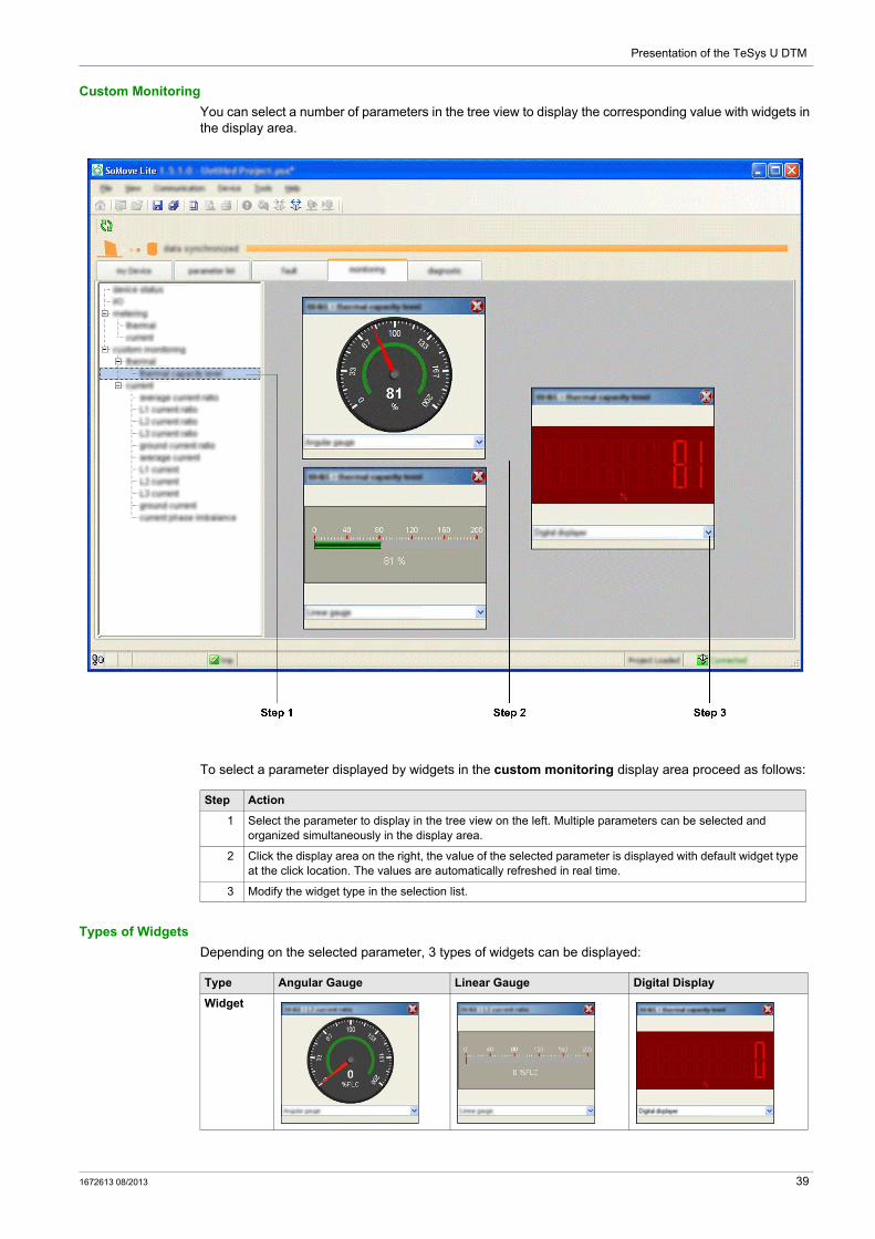
Custom Monitoring
You can select a number of parameters in the tree view to display the corresponding value with widgets in the display area.
To select a parameter displayed by widgets in the custom monitoring display area proceed as follows:
Types of Widgets
Depending on the selected parameter, 3 types of widgets can be displayed:
Step Action
1 Select the parameter to display in the tree view on the left. Multiple parameters can be selected and organized simultaneously in the display area.
2 Click the display area on the right, the value of the selected parameter is displayed with default widget type at the click location. The values are automatically refreshed in real time.
3 Modify the widget type in the selection list.
Type Angular Gauge Linear Gauge Digital Display
Widget
1672613 08/2013 39
Presentation of the TeSys U DTM
diagnostic Tab
Overview
This tab is available with the extended mode using SoMove.
The diagnostic tab displays statistics of the connected TeSys U starter-controller and companion devices.
The data in this tab is only significant in the connected mode.
Description
For a global description of this tab, refer to the tab zone description (see page 32).
The statistics tree view item is available in the diagnostic tab and displays: the LUCM control unit internal temperature (see page 51) the motor statistics (see page 59)
40 1672613 08/2013
TeSys U DTM for FDT Container
Metering and Monitoring Functions
1672613 08/2013
Metering and Monitoring Functions
Chapter 2Metering and Monitoring Functions
Overview
The TeSys U starter-controller provides measurement, metering, and monitoring in support of the current protection functions.
What Is in This Chapter?
This chapter contains the following sections:
Section Topic Page
2.1 Measurement 42
2.2 Device Monitoring Faults 49
2.3 Statistics 56
1672613 08/2013 41

Metering and Monitoring Functions
Measurement
Section 2.1Measurement
Overview
The TeSys U starter-controller uses measurements to perform protection, control, monitoring, and logic functions. Each measurement is detailed in this section.
The measurements can be accessed via: a PC running SoMove with the TeSys U DTM the LUCM Human Machine Interface (HMI) a PLC via the network port
What Is in This Section?
This section contains the following topics:
Topic Page
Line Currents 43
Ground Current 44
Average Current 45
Current Phase Imbalance 46
Thermal Capacity Level 47
Minimum Wait Time 48
42 1672613 08/2013
Metering and Monitoring Functions
Line Currents
Description
The TeSys U starter-controller measures line currents from internal sensors: 3-phase currents L1, L2, and L3, or single-phase current measured from L1 and L3.
The TeSys U selection guide (see page 16) provides information on the functions available depending on the control unit used.
Check your system configuration to ensure that the function is enabled in your application.
Line Current Ratio Characteristics
Line Current Formula
The line currents in Amps are calculated by the LUCM control unit and the TeSys U DTM for display according to the following formula:
Line current = (Line current ratio) x (FLAmax) x (Motor full load current ratio)
Line Current Characteristics
Characteristic Value
Unit % of FLA (see page 63)
Accuracy +/– 5 %
Resolution 1 % of FLA
Characteristic Value
Unit A
Accuracy +/– 5 %
Resolution 0.1 A
1672613 08/2013 43

Metering and Monitoring Functions
Ground Current
Description
The TeSys U starter-controller calculates the ground current from the 3 line currents measured.
The TeSys U selection guide (see page 16) provides information on the functions available depending on the control unit used.
Check your system configuration to ensure that the function is enabled in your application.
Ground Current Ratio Characteristics
Ground Current Formula
The ground current in Amps is calculated by the LUCM control unit and the TeSys U DTM for display according to the following formula:
Ground current = (Ground current ratio) x (FLAmax) / 4
Ground Current Characteristics
Characteristic Value
Unit % of FLAmin (see page 63)
Accuracy +/– 5 %
Resolution 1 % of FLAmin
Characteristic Value
Unit A
Accuracy +/– 5 %
Resolution 0.1 A
44 1672613 08/2013

Metering and Monitoring Functions
Average Current
Description
The TeSys U starter-controller calculates the average current from the line current ratio.
The TeSys U selection guide (see page 16) provides information on the functions available depending on the control unit used.
Check your system configuration to ensure that the function is enabled in your application.
Average Current Ratio Characteristics
Average Current Formula
The average current in Amps is calculated by the LUCM control unit and the TeSys U DTM for display according to the following formula:
Average current = (Average current ratio) x (FLAmax) x (Motor full load current ratio)
Average Current Characteristics
Characteristic Value
Unit % of FLA (see page 63)
Accuracy +/– 5 %
Resolution 1 % of FLA
Characteristic Value
Unit A
Accuracy +/– 5 %
Resolution 0.1 A
1672613 08/2013 45
Metering and Monitoring Functions
Current Phase Imbalance
Description
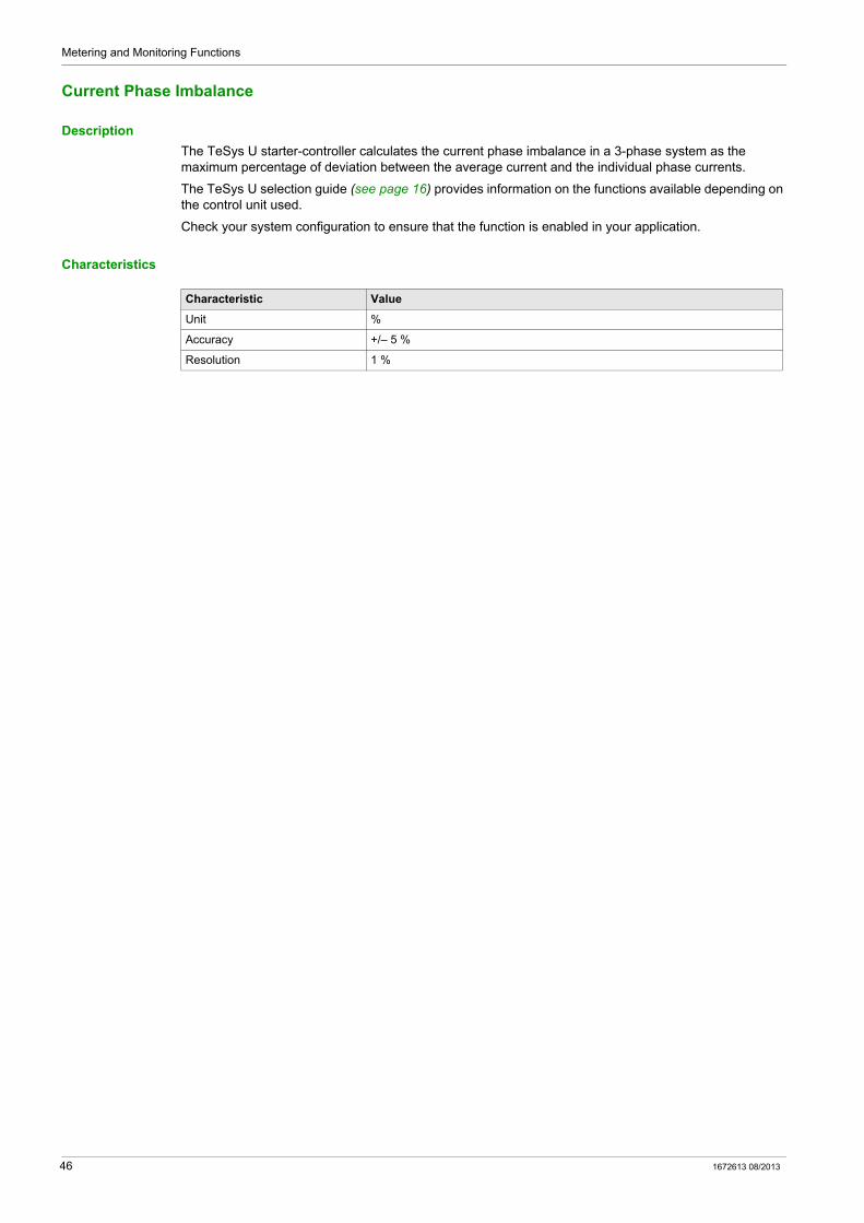
The TeSys U starter-controller calculates the current phase imbalance in a 3-phase system as the maximum percentage of deviation between the average current and the individual phase currents.
The TeSys U selection guide (see page 16) provides information on the functions available depending on the control unit used.
Check your system configuration to ensure that the function is enabled in your application.
Characteristics
Characteristic Value
Unit %
Accuracy +/– 5 %
Resolution 1 %
46 1672613 08/2013
Metering and Monitoring Functions
Thermal Capacity Level
Description
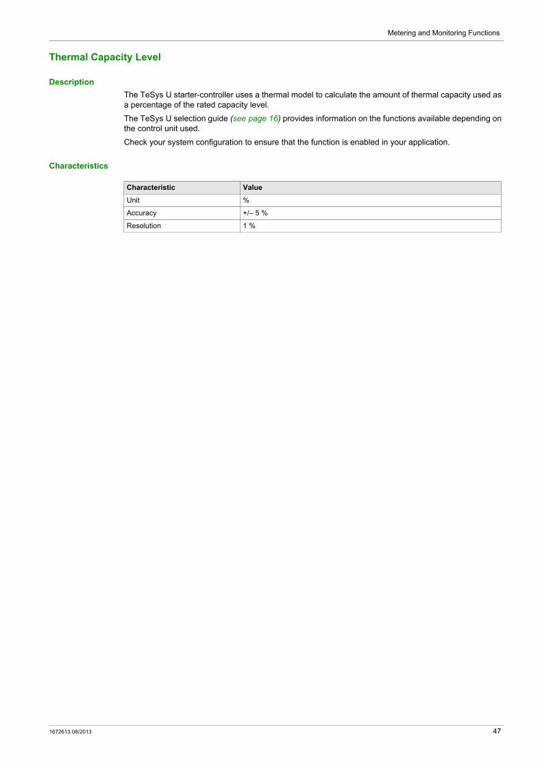
The TeSys U starter-controller uses a thermal model to calculate the amount of thermal capacity used as a percentage of the rated capacity level.
The TeSys U selection guide (see page 16) provides information on the functions available depending on the control unit used.
Check your system configuration to ensure that the function is enabled in your application.
Characteristics
Characteristic Value
Unit %
Accuracy +/– 5 %
Resolution 1 %
1672613 08/2013 47
Metering and Monitoring Functions
Minimum Wait Time
Description
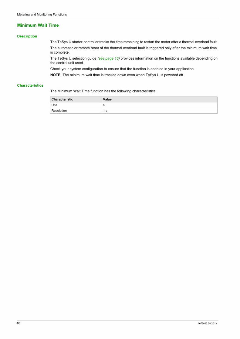
The TeSys U starter-controller tracks the time remaining to restart the motor after a thermal overload fault.
The automatic or remote reset of the thermal overload fault is triggered only after the minimum wait time is complete.
The TeSys U selection guide (see page 16) provides information on the functions available depending on the control unit used.
Check your system configuration to ensure that the function is enabled in your application.
NOTE: The minimum wait time is tracked down even when TeSys U is powered off.
Characteristics
The Minimum Wait Time function has the following characteristics:
Characteristic Value
Unit s
Resolution 1 s
48 1672613 08/2013
Metering and Monitoring Functions
Device Monitoring Faults
Section 2.2Device Monitoring Faults
Overview
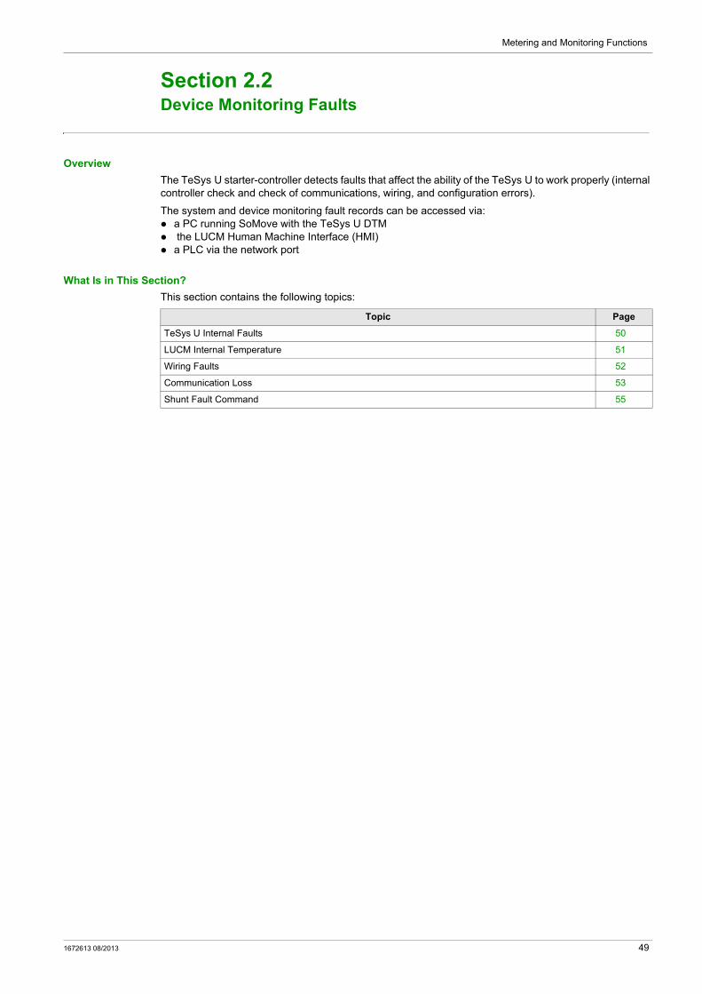
The TeSys U starter-controller detects faults that affect the ability of the TeSys U to work properly (internal controller check and check of communications, wiring, and configuration errors).
The system and device monitoring fault records can be accessed via: a PC running SoMove with the TeSys U DTM the LUCM Human Machine Interface (HMI) a PLC via the network port
What Is in This Section?
This section contains the following topics:
Topic Page
TeSys U Internal Faults 50
LUCM Internal Temperature 51
Wiring Faults 52
Communication Loss 53
Shunt Fault Command 55
1672613 08/2013 49
Metering and Monitoring Functions
TeSys U Internal Faults
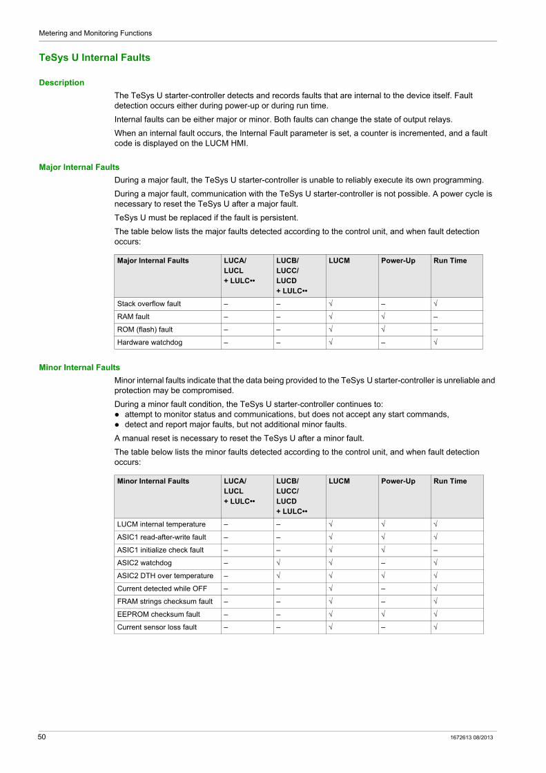
Description
The TeSys U starter-controller detects and records faults that are internal to the device itself. Fault detection occurs either during power-up or during run time.
Internal faults can be either major or minor. Both faults can change the state of output relays.
When an internal fault occurs, the Internal Fault parameter is set, a counter is incremented, and a fault code is displayed on the LUCM HMI.
Major Internal Faults
During a major fault, the TeSys U starter-controller is unable to reliably execute its own programming.
During a major fault, communication with the TeSys U starter-controller is not possible. A power cycle is necessary to reset the TeSys U after a major fault.
TeSys U must be replaced if the fault is persistent.
The table below lists the major faults detected according to the control unit, and when fault detection occurs:
Minor Internal Faults
Minor internal faults indicate that the data being provided to the TeSys U starter-controller is unreliable and protection may be compromised.
During a minor fault condition, the TeSys U starter-controller continues to: attempt to monitor status and communications, but does not accept any start commands, detect and report major faults, but not additional minor faults.
A manual reset is necessary to reset the TeSys U after a minor fault.
The table below lists the minor faults detected according to the control unit, and when fault detection occurs:
Major Internal Faults LUCA/LUCL+ LULC••
LUCB/LUCC/LUCD+ LULC••
LUCM Power-Up Run Time
Stack overflow fault – – √ – √
RAM fault – – √ √ –
ROM (flash) fault – – √ √ –
Hardware watchdog – – √ – √
Minor Internal Faults LUCA/LUCL+ LULC••
LUCB/LUCC/LUCD+ LULC••
LUCM Power-Up Run Time
LUCM internal temperature – – √ √ √
ASIC1 read-after-write fault – – √ √ √
ASIC1 initialize check fault – – √ √ –
ASIC2 watchdog – √ √ – √
ASIC2 DTH over temperature – √ √ √ √
Current detected while OFF – – √ – √
FRAM strings checksum fault – – √ – √
EEPROM checksum fault – – √ √ √
Current sensor loss fault – – √ – √
50 1672613 08/2013
Metering and Monitoring Functions
LUCM Internal Temperature
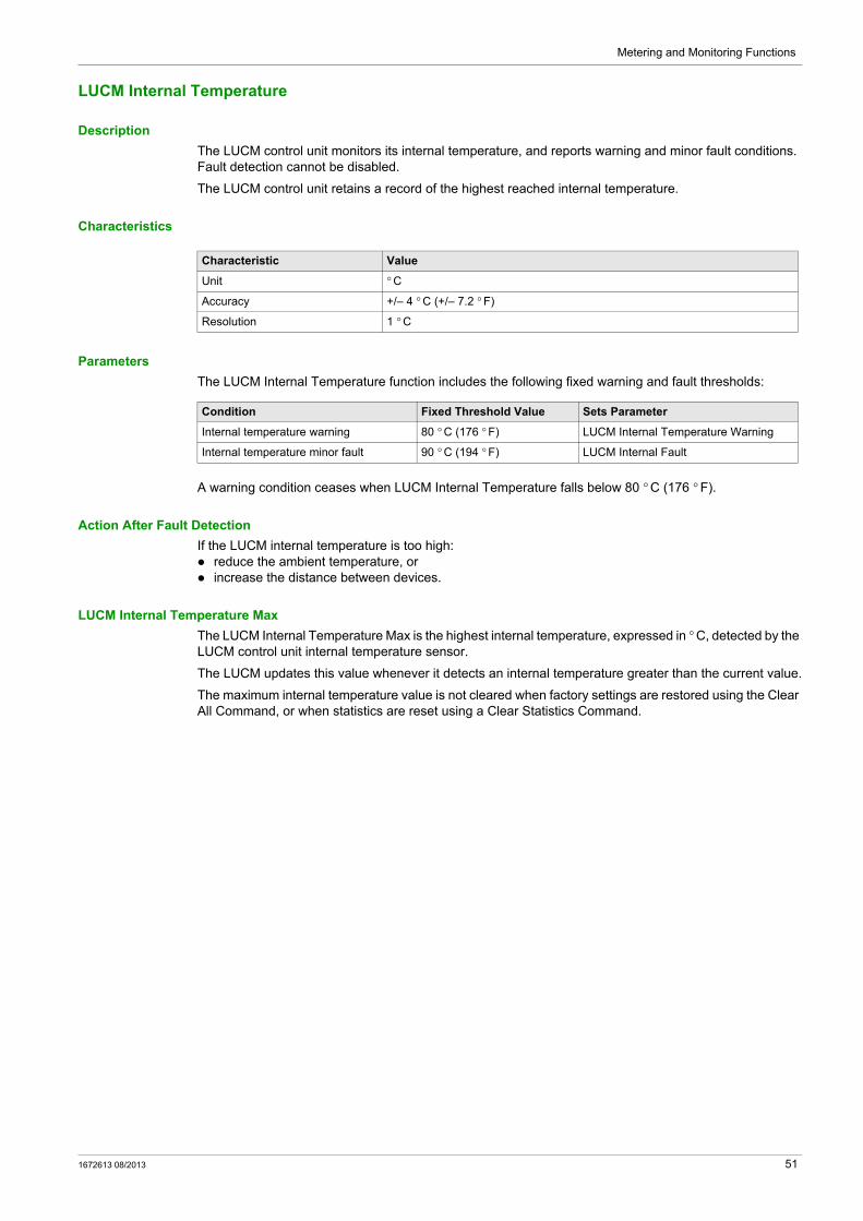
Description
The LUCM control unit monitors its internal temperature, and reports warning and minor fault conditions. Fault detection cannot be disabled.
The LUCM control unit retains a record of the highest reached internal temperature.
Characteristics
Parameters
The LUCM Internal Temperature function includes the following fixed warning and fault thresholds:
A warning condition ceases when LUCM Internal Temperature falls below 80 ° C (176 ° F).
Action After Fault Detection
If the LUCM internal temperature is too high: reduce the ambient temperature, or increase the distance between devices.
LUCM Internal Temperature Max
The LUCM Internal Temperature Max is the highest internal temperature, expressed in ° C, detected by the LUCM control unit internal temperature sensor.
The LUCM updates this value whenever it detects an internal temperature greater than the current value.
The maximum internal temperature value is not cleared when factory settings are restored using the Clear All Command, or when statistics are reset using a Clear Statistics Command.
Characteristic Value
Unit ° C
Accuracy +/– 4 ° C (+/– 7.2 ° F)
Resolution 1 ° C
Condition Fixed Threshold Value Sets Parameter
Internal temperature warning 80 ° C (176 ° F) LUCM Internal Temperature Warning
Internal temperature minor fault 90 ° C (194 ° F) LUCM Internal Fault
1672613 08/2013 51

Metering and Monitoring Functions
Wiring Faults
Description
The LUCM control unit checks external wiring connections and reports a fault when it detects incorrect or conflicting external wiring. It detects 3 types of wiring errors: Phase Configuration Error A2 missing A1 overvoltage
Phase Configuration Error
The LUCM control unit checks all 3 motor phases and reports an error if it detects current in phase 2, if the TeSys U is configured for single-phase operation.
A2 Missing
The LUCM control unit checks that the A2 terminal on the TeSys U power base is connected to 0 Vdc.
A1 Overvoltage
The LUCM control unit checks that the voltage on A1–A2 terminals on the TeSys U power base is in the correct range.
If the voltage is greater than 34 Vdc, this fault is reported.
52 1672613 08/2013

Metering and Monitoring Functions
Communication Loss
Description
The TeSys U starter-controller monitors communication through: the network port on the LULC•• communication module the HMI port on the LUCM control unit
Network Port Communication Loss
The TeSys U starter-controller monitors network communication through the network port on the LULC•• communication module and reports a warning when network communication is lost: With the LULC031 or LULC033 Modbus communication module, the communication is lost for a time
period equal to, or longer than, an adjustable parameter, the Network port watchdog timeout (refer to Configuration of the LULC•• Network Port, page 96).
With other LULC•• communication modules, the communication loss detection is part of the protocol management, without adjustable parameters.
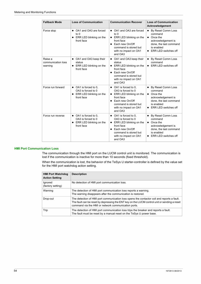
When the network communication is lost, the TeSys U starter-controller switches to Fallback mode.
Network Port Communication Loss Fallback Strategy
The communication loss fallback strategy parameter is used to adjust the fallback mode in case of communication loss with the PLC.
The different fallback modes are: Ignore communication loss Freeze outputs Force stop Raise a communication loss warning Force run forward Force run reverse
The following table describes the different fallback modes:
WARNINGAUTOMATIC RESTART OF THE MOTOR
If communication is stopped, outputs OA1–OA3 take the status corresponding to the selected fallback mode, but the control bits Motor Run Forward Command and Motor Run Reverse Command are not modified.
When a loss of communication warning is acknowledged though the communication network using the Reset Comm Loss command, the motor automatically restarts if the control bits were not previously overwritten to 0 by the PLC application.
Failure to follow these instructions can result in death, serious injury, or equipment damage.
Fallback Mode Loss of Communication Communication Recover Loss of Communication Acknowledgement
Ignore communication loss
No detection of the loss of communication
OA1 and OA3 keep their status
No detection of the loss of communication
OA1 and OA3 keep their status
No acknowledgement of the loss of communication
Freeze outputs OA1 and OA3 keep their status
ERR LED blinking on the front face
OA1 and OA3 keep their status
ERR LED blinking on the front face
Each new On/Off command is stored but with no impact on OA1 and OA3
By Reset Comm Loss command
Once the acknowledgement is done, the last command is enabled
ERR LED switches off
1672613 08/2013 53
Metering and Monitoring Functions
HMI Port Communication Loss
The communication through the HMI port on the LUCM control unit is monitored. The communication is lost if the communication is inactive for more than 10 seconds (fixed threshold).
When the communication is lost, the behavior of the TeSys U starter-controller is defined by the value set for the HMI port watchdog action setting.
Force stop OA1 and OA3 are forced to 0
ERR LED blinking on the front face
OA1 and OA3 are forced to 0
ERR LED blinking on the front face
Each new On/Off command is stored but with no impact on OA1 and OA3
By Reset Comm Loss command
Once the acknowledgement is done, the last command is enabled
ERR LED switches off
Raise a communication loss warning
OA1 and OA3 keep their status
ERR LED blinking on the front face
OA1 and OA3 keep their status
ERR LED blinking on the front face
Each new On/Off command is stored but with no impact on OA1 and OA3
By Reset Comm Loss command
ERR LED switches off
Force run forward OA1 is forced to 0, OA3 is forced to 0
ERR LED blinking on the front face
OA1 is forced to 0, OA3 is forced to 0
ERR LED blinking on the front face
Each new On/Off command is stored but with no impact on OA1 and OA3
By Reset Comm Loss command
Once the acknowledgement is done, the last command is enabled
ERR LED switches off
Force run reverse OA1 is forced to 0, OA3 is forced to 0
ERR LED blinking on the front face
OA1 is forced to 0, OA3 is forced to 0
ERR LED blinking on the front face
Each new On/Off command is stored but with no impact on OA1 and OA3
By Reset Comm Loss command
Once the acknowledgement is done, the last command is enabled
ERR LED switches off
Fallback Mode Loss of Communication Communication Recover Loss of Communication Acknowledgement
HMI Port Watchdog Action Setting
Description
Ignored(factory setting)
No detection of HMI port communication loss.
Warning The detection of HMI port communication loss reports a warning.The warning disappears after the communication is restored.
Drop-out The detection of HMI port communication loss opens the contactor coil and reports a fault.The fault can be reset by depressing the ENT key on the LUCM control unit or sending a reset command via the HMI or network communication ports.
Trip The detection of HMI port communication loss trips the breaker and reports a fault.The fault must be reset by a manual reset on the TeSys U power base.
54 1672613 08/2013
Metering and Monitoring Functions
Shunt Fault Command
Description
The TeSys U starter-controller may receive a trip command sent by an external device via the communication network.
This external trip command is triggered by setting the parameter Shunt Fault Command.
The starter-controller must be manually reset after clearing the Shunt Fault Command.
1672613 08/2013 55
Metering and Monitoring Functions
Statistics
Section 2.3Statistics
Overview
The TeSys U starter-controller with an LUCM control unit records statistics that can be retrieved for operational analysis.
The TeSys U statistic parameters can be accessed via: a PC running SoMove with the TeSys U DTM the LUCM Human Machine Interface (HMI) a PLC via the network port
All statistic parameters are reset by executing the Clear Statistics Command or the Clear All Command.
What Is in This Section?
This section contains the following topics:
Topic Page
Fault and Warning Counters 57
Fault History 58
Motor Statistics 59
56 1672613 08/2013
Metering and Monitoring Functions
Fault and Warning Counters
About Counters
A counter contains a value from 0 to 65,535 and increments by a value of 1 when the event related to this counter occurs.
Counters are saved on power loss.
Protection Fault Counters
Protection fault counters include: Short-Circuit Faults Count Magnetic Faults Count Ground Current Faults Count Thermal Overload Faults Count Long Start Faults Count Jam Faults Count Phase Imbalance Faults Count Undercurrent Faults Count Shunt Faults Count
Protection Warning Counters
The Thermal Overload Warnings Count is the only warning counter available.
Communication Loss Counters
Communication loss counters include: HMI Port Faults Count: number of times communications via the HMI port on the LUCM control unit was
lost. Network Port Drop-out Faults Count: number of times the LULC•• communication module generates a
drop-out. Network Port Trip Faults Count: number of times the LULC•• communication module generates a trip.
Internal Fault Counters
Internal fault counters include: Controller Internal Faults Count: number of major and minor internal faults (see page 50). Internal Port Faults Count: number of TeSys U internal communication faults, plus the number of failed
attempts to identify the network communication module. Network Port Internal Faults Count: number of internal faults experienced by the LULC•• communication
module.
1672613 08/2013 57
Metering and Monitoring Functions
Fault History
Fault History
The TeSys U starter-controller records the last 5 detected faults.
Fault n–0 contains the most recent fault record, and Fault n–4 contains the oldest retained fault record.
Each fault record includes: Fault code Value of Setting Motor Full Load Amps Ratio (% of FLAmax) Value of measurements: Thermal Capacity Level
Average Current Ratio
L1, L2, L3 Current Ratio
Ground Current Ratio
58 1672613 08/2013
Metering and Monitoring Functions
Motor Statistics
Motor Starts Counters
The TeSys U starter-controller counts the number of motor starts and records the data as a statistic that can be retrieved for operational analysis.
Operating Time
The TeSys U starter-controller tracks motor operating time and records the value in the Operating Time parameter.
Use this information to help schedule motor maintenance, such as lubrication, inspection, and replacement.
1672613 08/2013 59

Metering and Monitoring Functions
60 1672613 08/2013

TeSys U DTM for FDT Container
Motor Protection Functions
1672613 08/2013
Motor Protection Functions
Chapter 3Motor Protection Functions
Overview
This chapter describes the motor protection functions provided by the TeSys U starter-controller.
What Is in This Chapter?
This chapter contains the following topics:
Topic Page
Motor Protection Characteristics 62
FLA (Full Load Amps) Settings 63
Thermal Overload 64
Short-Circuit 67
Magnetic 68
Ground Current 69
Current Phase Imbalance 71
Long Start 74
Jam 76
Undercurrent 78
1672613 08/2013 61
Motor Protection Functions
Motor Protection Characteristics
Introduction
The TeSys U starter-controller monitors line current and ground current. The TeSys U starter-controller uses parameters in protection functions to detect fault and warning conditions.
All motor protection functions include fault detection, and most protection functions also include warning detection.
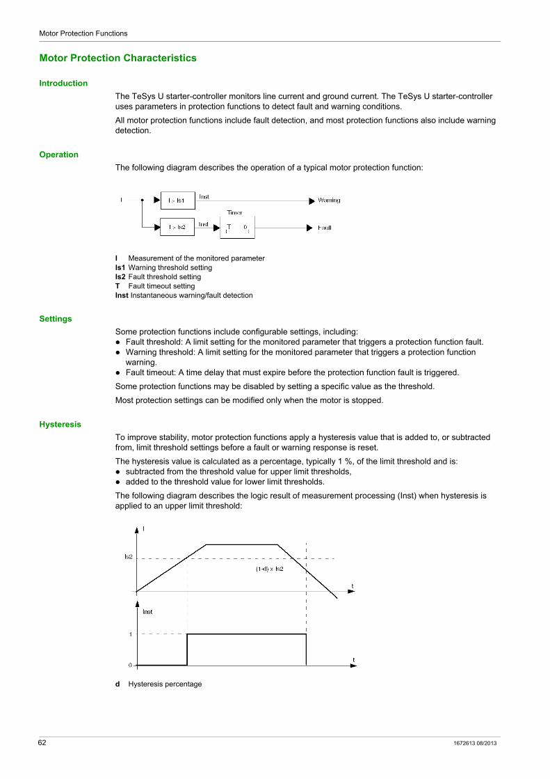
Operation
The following diagram describes the operation of a typical motor protection function:
I Measurement of the monitored parameterIs1 Warning threshold settingIs2 Fault threshold settingT Fault timeout settingInst Instantaneous warning/fault detection
Settings
Some protection functions include configurable settings, including: Fault threshold: A limit setting for the monitored parameter that triggers a protection function fault. Warning threshold: A limit setting for the monitored parameter that triggers a protection function
warning. Fault timeout: A time delay that must expire before the protection function fault is triggered.
Some protection functions may be disabled by setting a specific value as the threshold.
Most protection settings can be modified only when the motor is stopped.
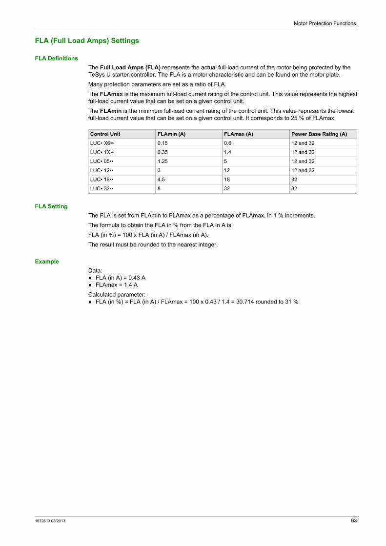
Hysteresis
To improve stability, motor protection functions apply a hysteresis value that is added to, or subtracted from, limit threshold settings before a fault or warning response is reset.
The hysteresis value is calculated as a percentage, typically 1 %, of the limit threshold and is: subtracted from the threshold value for upper limit thresholds, added to the threshold value for lower limit thresholds.
The following diagram describes the logic result of measurement processing (Inst) when hysteresis is applied to an upper limit threshold:
d Hysteresis percentage
62 1672613 08/2013
Motor Protection Functions
FLA (Full Load Amps) Settings
FLA Definitions
The Full Load Amps (FLA) represents the actual full-load current of the motor being protected by the TeSys U starter-controller. The FLA is a motor characteristic and can be found on the motor plate.
Many protection parameters are set as a ratio of FLA.
The FLAmax is the maximum full-load current rating of the control unit. This value represents the highest full-load current value that can be set on a given control unit.
The FLAmin is the minimum full-load current rating of the control unit. This value represents the lowest full-load current value that can be set on a given control unit. It corresponds to 25 % of FLAmax.
FLA Setting
The FLA is set from FLAmin to FLAmax as a percentage of FLAmax, in 1 % increments.
The formula to obtain the FLA in % from the FLA in A is:
FLA (in %) = 100 x FLA (in A) / FLAmax (in A).
The result must be rounded to the nearest integer.
Example
Data: FLA (in A) = 0.43 A FLAmax = 1.4 A
Calculated parameter: FLA (in %) = FLA (in A) / FLAmax = 100 x 0.43 / 1.4 = 30.714 rounded to 31 %
Control Unit FLAmin (A) FLAmax (A) Power Base Rating (A)
LUC• X6•• 0.15 0.6 12 and 32
LUC• 1X•• 0.35 1.4 12 and 32
LUC• 05•• 1.25 5 12 and 32
LUC• 12•• 3 12 12 and 32
LUC• 18•• 4.5 18 32
LUC• 32•• 8 32 32
1672613 08/2013 63
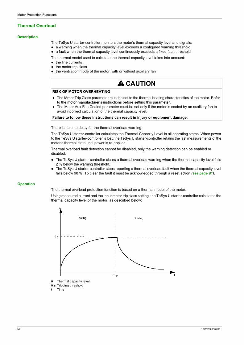
Motor Protection Functions
Thermal Overload
Description
The TeSys U starter-controller monitors the motor’s thermal capacity level and signals: a warning when the thermal capacity level exceeds a configured warning threshold a fault when the thermal capacity level continuously exceeds a fixed fault threshold
The thermal model used to calculate the thermal capacity level takes into account: the line currents the motor trip class the ventilation mode of the motor, with or without auxiliary fan
There is no time delay for the thermal overload warning.
The TeSys U starter-controller calculates the Thermal Capacity Level in all operating states. When power to the TeSys U starter-controller is lost, the TeSys U starter-controller retains the last measurements of the motor’s thermal state until power is re-applied.
Thermal overload fault detection cannot be disabled, only the warning detection can be enabled or disabled.
The TeSys U starter-controller clears a thermal overload warning when the thermal capacity level falls 2 % below the warning threshold.
The TeSys U starter-controller stops reporting a thermal overload fault when the thermal capacity level falls below 98 %. To clear the fault it must be acknowledged through a reset action (see page 91).
Operation
The thermal overload protection function is based on a thermal model of the motor.
Using measured current and the input motor trip class setting, the TeSys U starter-controller calculates the thermal capacity level of the motor, as described below:
θ Thermal capacity levelθ s Tripping thresholdt Time
CAUTIONRISK OF MOTOR OVERHEATING
The Motor Trip Class parameter must be set to the thermal heating characteristics of the motor. Refer to the motor manufacturer’s instructions before setting this parameter.
The Motor Aux Fan Cooled parameter must be set only if the motor is cooled by an auxiliary fan to avoid incorrect calculation of the thermal capacity level.
Failure to follow these instructions can result in injury or equipment damage.
64 1672613 08/2013
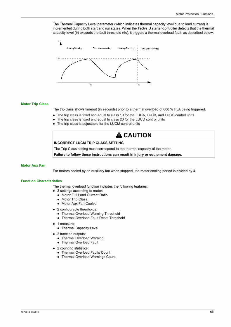
Motor Protection Functions
The Thermal Capacity Level parameter (which indicates thermal capacity level due to load current) is incremented during both start and run states. When the TeSys U starter-controller detects that the thermal capacity level (θ) exceeds the fault threshold (θs), it triggers a thermal overload fault, as described below:
Motor Trip Class
The trip class shows timeout (in seconds) prior to a thermal overload of 600 % FLA being triggered.
The trip class is fixed and equal to class 10 for the LUCA, LUCB, and LUCC control units The trip class is fixed and equal to class 20 for the LUCD control units The trip class is adjustable for the LUCM control units
Motor Aux Fan
For motors cooled by an auxiliary fan when stopped, the motor cooling period is divided by 4.
Function Characteristics
The thermal overload function includes the following features: 3 settings according to motor: Motor Full Load Current Ratio Motor Trip Class Motor Aux Fan Cooled
2 configurable thresholds: Thermal Overload Warning Threshold Thermal Overload Fault Reset Threshold
1 measure: Thermal Capacity Level
2 function outputs: Thermal Overload Warning Thermal Overload Fault
2 counting statistics: Thermal Overload Faults Count Thermal Overload Warnings Count
CAUTIONINCORRECT LUCM TRIP CLASS SETTING
The Trip Class setting must correspond to the thermal capacity of the motor.
Failure to follow these instructions can result in injury or equipment damage.
1672613 08/2013 65

Motor Protection Functions
Block Diagram
Imax Maximum currentθmax Thermal capacity levelθs1 Thermal overload warning threshold
Parameter Settings
The thermal overload function has the following configurable parameter settings:
The thermal overload function has the following non-configurable parameter settings:
Technical Characteristics
The thermal overload function has the following characteristics:
Automatic Reset
In automatic fault reset mode, the thermal overload fault is automatically reset if the thermal capacity level is lower than the fault reset threshold and the fault reset timeout has elapsed.
Parameter Setting Range Factory Setting
Motor full load current ratio 25...100 % of FLAmax 25 % of FLAmax
Motor trip class 5...30 in increments of 5 5
Motor aux fan cooled Yes/No No
Warning threshold 0 to disable the warning detection, or 10...100 % of thermal capacity level
85 % of thermal capacity level
Fault reset timeout 1...1,000 s in 1 s increments 120 s
Fault reset threshold 35...95 % of thermal capacity level in increments of 5 %
80 % of thermal capacity level
Parameter Fixed Setting
Thermal overload fault threshold 100 % of thermal capacity level
Characteristic Value
Hysteresis –1 % of thermal overload warning threshold
Trip time accuracy +/– 0.1 s
NOTICEINCORRECT RESET TIMEOUT SETTING
Thermal reset timeout must be sufficient to allow motor to cool after a thermal trip. See the motor manufacturer’s instructions before adjusting this setting.
Failure to follow these instructions can result in equipment damage.
66 1672613 08/2013

Motor Protection Functions
Short-Circuit
Description
The short-circuit function detects a fault when the phase current exceeds the fixed threshold of 14.2 x FLAmax.
The purpose of the short-circuit function is to provide a fast trip (faster than the magnetic overload function) when very high currents are detected.
Fault detection cannot be disabled.
This function has no warning.
Function Characteristics
The short-circuit function includes the following features: 1 function output: Short-circuit Fault
1 counting statistic: Short-circuit Faults Count
Block Diagram
I1 Phase 1 currentI2 Phase 2 currentI3 Phase 3 current
1672613 08/2013 67
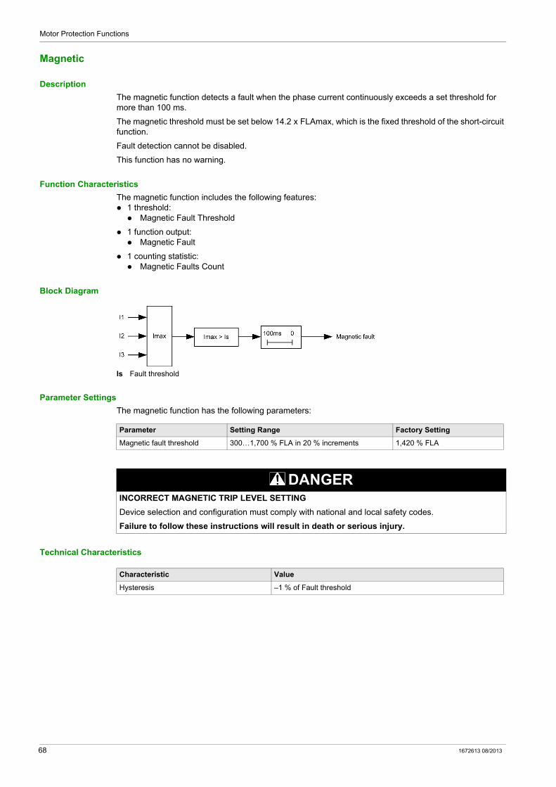
Motor Protection Functions
Magnetic
Description
The magnetic function detects a fault when the phase current continuously exceeds a set threshold for more than 100 ms.
The magnetic threshold must be set below 14.2 x FLAmax, which is the fixed threshold of the short-circuit function.
Fault detection cannot be disabled.
This function has no warning.
Function Characteristics
The magnetic function includes the following features: 1 threshold: Magnetic Fault Threshold
1 function output: Magnetic Fault
1 counting statistic: Magnetic Faults Count
Block Diagram
Is Fault threshold
Parameter Settings
The magnetic function has the following parameters:
Technical Characteristics
Parameter Setting Range Factory Setting
Magnetic fault threshold 300…1,700 % FLA in 20 % increments 1,420 % FLA
DANGERINCORRECT MAGNETIC TRIP LEVEL SETTING
Device selection and configuration must comply with national and local safety codes.
Failure to follow these instructions will result in death or serious injury.
Characteristic Value
Hysteresis –1 % of Fault threshold
68 1672613 08/2013
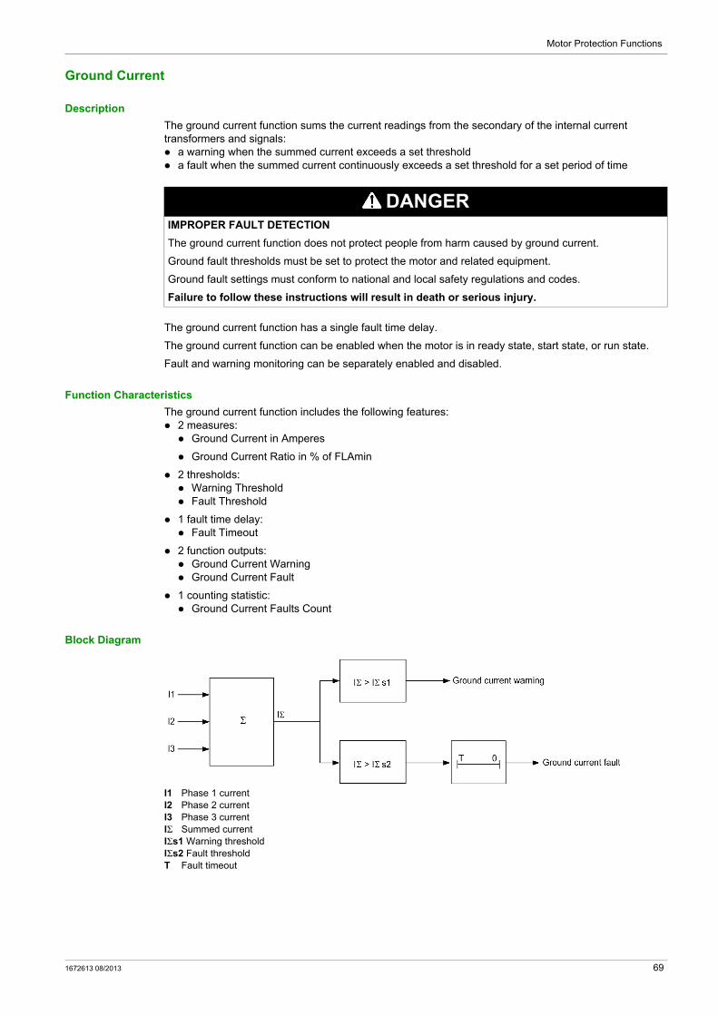
Motor Protection Functions
Ground Current
Description
The ground current function sums the current readings from the secondary of the internal current transformers and signals: a warning when the summed current exceeds a set threshold a fault when the summed current continuously exceeds a set threshold for a set period of time
The ground current function has a single fault time delay.
The ground current function can be enabled when the motor is in ready state, start state, or run state.
Fault and warning monitoring can be separately enabled and disabled.
Function Characteristics
The ground current function includes the following features: 2 measures: Ground Current in Amperes
Ground Current Ratio in % of FLAmin
2 thresholds: Warning Threshold Fault Threshold
1 fault time delay: Fault Timeout
2 function outputs: Ground Current Warning Ground Current Fault
1 counting statistic: Ground Current Faults Count
Block Diagram
I1 Phase 1 currentI2 Phase 2 currentI3 Phase 3 currentIΣ Summed currentIΣs1 Warning thresholdIΣs2 Fault thresholdT Fault timeout
DANGERIMPROPER FAULT DETECTION
The ground current function does not protect people from harm caused by ground current.
Ground fault thresholds must be set to protect the motor and related equipment.
Ground fault settings must conform to national and local safety regulations and codes.
Failure to follow these instructions will result in death or serious injury.
1672613 08/2013 69
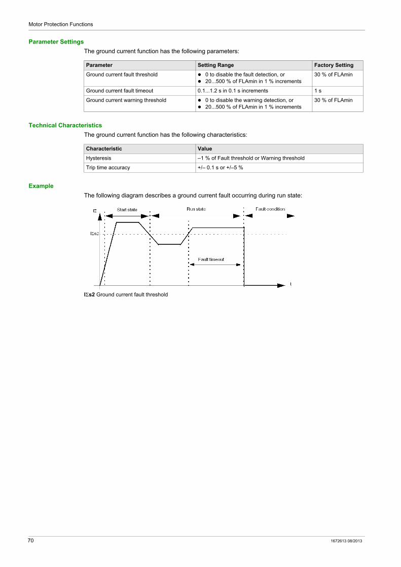
Motor Protection Functions
Parameter Settings
The ground current function has the following parameters:
Technical Characteristics
The ground current function has the following characteristics:
Example
The following diagram describes a ground current fault occurring during run state:
IΣs2 Ground current fault threshold
Parameter Setting Range Factory Setting
Ground current fault threshold 0 to disable the fault detection, or 20...500 % of FLAmin in 1 % increments
30 % of FLAmin
Ground current fault timeout 0.1...1.2 s in 0.1 s increments 1 s
Ground current warning threshold 0 to disable the warning detection, or 20...500 % of FLAmin in 1 % increments
30 % of FLAmin
Characteristic Value
Hysteresis –1 % of Fault threshold or Warning threshold
Trip time accuracy +/– 0.1 s or +/–5 %
70 1672613 08/2013
Motor Protection Functions
Current Phase Imbalance
Description
The current phase imbalance function signals: a warning when the current in any phase differs by more than a set percentage from the average current
in all 3 phases a fault when the current in any phase differs by more than a set percentage from the average current in
all 3 phases for a set period of time
The function is enabled only if the average current in all 3 phases is greater than 25 % of FLA.
This function has 2 adjustable fault time delays: one applies to current imbalances occurring while the motor is starting up one applies to current imbalances occurring after startup while the motor is running
Fault and warning monitoring can be separately enabled and disabled.
The function applies only to 3-phase motors.
Function Characteristics
The current phase imbalance function includes the following features: 2 thresholds: Warning Threshold Fault Threshold
2 fault time delays: Fault Timeout Starting Fault Timeout Running
1 measure: Current Phase Imbalance
2 function outputs: Current Phase Imbalance Warning Current Phase Imbalance Fault
1 counting statistic: Current Phase Imbalance Faults Count
CAUTIONRISK OF MOTOR OVERHEATING
The Current Phase Imbalance Fault Threshold must be properly set to protect the wiring and motor equipment from harm caused by motor overheating.
The value you input must conform to national and local safety regulations and codes. Refer to the motor manufacturer’s instructions before setting this parameter.
Failure to follow these instructions can result in injury or equipment damage.
1672613 08/2013 71

Motor Protection Functions
Block Diagram
Current phase imbalance warning and fault:
I1 Phase 1 currentI2 Phase 2 currentI3 Phase 3 currentIimb Current imbalance ratio for 3-phaseIs1 Warning thresholdIs2 Fault thresholdT1 Fault timeout startingT2 Fault timeout running
Parameter Settings
The current phase imbalance function has the following parameters:
Technical Characteristics
The current phase imbalance function has the following characteristics:
Parameter Setting Range Factory Setting
Fault threshold 0 to disable the fault detection, or 10...30 % of the calculated imbalance in 1 % increments
10 %
Fault timeout starting 0.2...20 s in 0.1 s increments 0.7 s
Fault timeout running 0.2...20 s in 0.1 s increments 5 s
Warning threshold 0 to disable the warning detection, or 10...30 % of the calculated imbalance in 1 % increments
10 %
Characteristic Value
Hysteresis –1 % of fault or warning threshold
Trip time accuracy +/–0.3 s or +/–5 %
72 1672613 08/2013
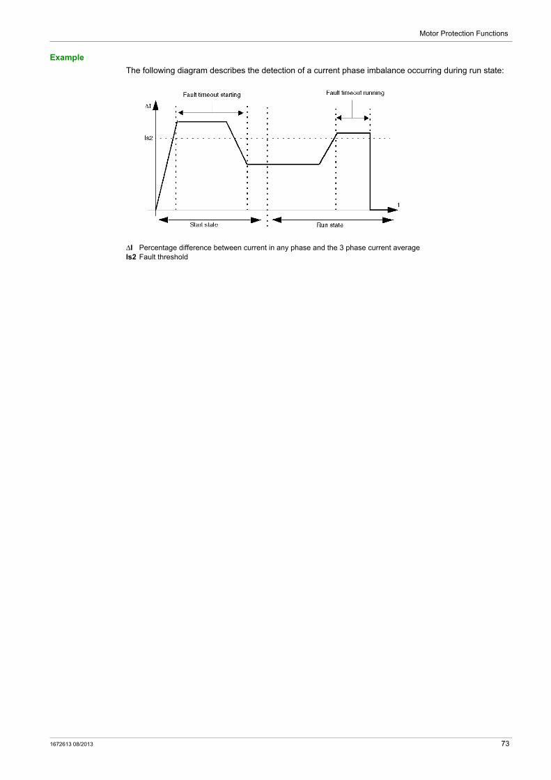
Motor Protection Functions
Example
The following diagram describes the detection of a current phase imbalance occurring during run state:
ΔI Percentage difference between current in any phase and the 3 phase current averageIs2 Fault threshold
1672613 08/2013 73

Motor Protection Functions
Long Start
Description
The long start function detects a locked or stalled rotor in start state and signals: a warning when current exceeds a separately set threshold a fault when current continuously exceeds a separately set threshold for a set period of time
Each predefined operating mode has its own current profile, representing a successful start cycle for the motor. The TeSys U starter-controller detects a long start fault condition whenever the actual current profile, occurring after a start command, varies from the expected profile.
The long start function signals a warning when a fault related to this problem occurs.
Fault and warning monitoring can be separately enabled and disabled.
Start Cycle
The configurable parameters for the Long Start protection function, Long Start Fault Threshold, and Long Start Fault Timeout are used by the TeSys U starter-controller when defining and detecting the motor’s start cycle (see page 84).
Function Characteristics
The long start function includes the following features: 2 thresholds: Warning Threshold Fault Threshold
1 fault time delay: Fault Timeout
2 function outputs: Long Start Warning Long Start Fault
1 counting statistic: Long Start Faults Count
Block Diagram
I1 Phase 1 currentI2 Phase 2 currentI3 Phase 3 currentIs1 Warning thresholdIs2 Fault thresholdT Fault timeout
Parameter Settings
The long start function has the following parameters:
Parameter Setting Range Factory Setting
Fault threshold 0 to disable the fault detection, or 100...800 % of FLA in 10 % increments
100 % of FLA
Fault timeout 1...200 s in 1 s increments 10 s
Warning threshold 0 to disable the warning detection, or 100...800 % of FLA in 10 % increments
0
74 1672613 08/2013
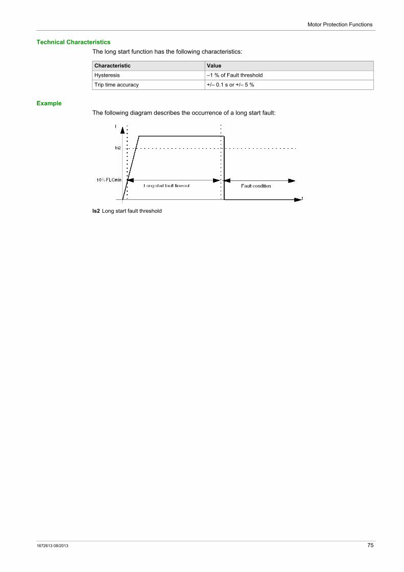
Motor Protection Functions
Technical Characteristics
The long start function has the following characteristics:
Example
The following diagram describes the occurrence of a long start fault:
Is2 Long start fault threshold
Characteristic Value
Hysteresis –1 % of Fault threshold
Trip time accuracy +/– 0.1 s or +/– 5 %
1672613 08/2013 75
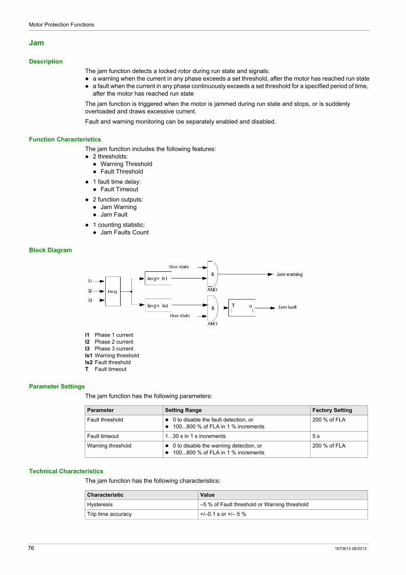
Motor Protection Functions
Jam
Description
The jam function detects a locked rotor during run state and signals: a warning when the current in any phase exceeds a set threshold, after the motor has reached run state a fault when the current in any phase continuously exceeds a set threshold for a specified period of time,
after the motor has reached run state
The jam function is triggered when the motor is jammed during run state and stops, or is suddenly overloaded and draws excessive current.
Fault and warning monitoring can be separately enabled and disabled.
Function Characteristics
The jam function includes the following features: 2 thresholds: Warning Threshold Fault Threshold
1 fault time delay: Fault Timeout
2 function outputs: Jam Warning Jam Fault
1 counting statistic: Jam Faults Count
Block Diagram
I1 Phase 1 currentI2 Phase 2 currentI3 Phase 3 currentIs1 Warning thresholdIs2 Fault thresholdT Fault timeout
Parameter Settings
The jam function has the following parameters:
Technical Characteristics
The jam function has the following characteristics:
Parameter Setting Range Factory Setting
Fault threshold 0 to disable the fault detection, or 100...800 % of FLA in 1 % increments
200 % of FLA
Fault timeout 1...30 s in 1 s increments 5 s
Warning threshold 0 to disable the warning detection, or 100...800 % of FLA in 1 % increments
200 % of FLA
Characteristic Value
Hysteresis –5 % of Fault threshold or Warning threshold
Trip time accuracy +/–0.1 s or +/– 5 %
76 1672613 08/2013
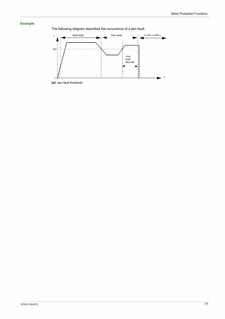
Motor Protection Functions
Example
The following diagram describes the occurrence of a jam fault:
Is2 Jam fault threshold
1672613 08/2013 77
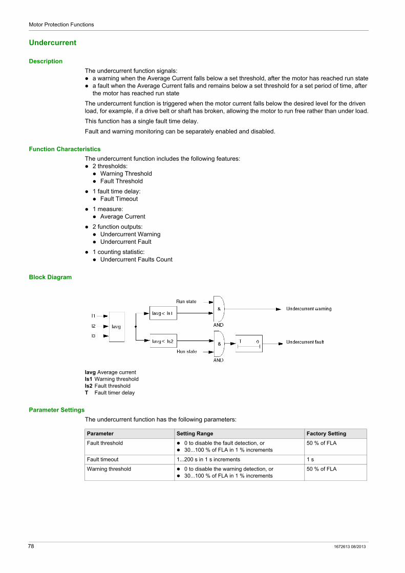
Motor Protection Functions
Undercurrent
Description
The undercurrent function signals: a warning when the Average Current falls below a set threshold, after the motor has reached run state a fault when the Average Current falls and remains below a set threshold for a set period of time, after
the motor has reached run state
The undercurrent function is triggered when the motor current falls below the desired level for the driven load, for example, if a drive belt or shaft has broken, allowing the motor to run free rather than under load.
This function has a single fault time delay.
Fault and warning monitoring can be separately enabled and disabled.
Function Characteristics
The undercurrent function includes the following features: 2 thresholds: Warning Threshold Fault Threshold
1 fault time delay: Fault Timeout
1 measure: Average Current
2 function outputs: Undercurrent Warning Undercurrent Fault
1 counting statistic: Undercurrent Faults Count
Block Diagram
Iavg Average currentIs1 Warning thresholdIs2 Fault thresholdT Fault timer delay
Parameter Settings
The undercurrent function has the following parameters:
Parameter Setting Range Factory Setting
Fault threshold 0 to disable the fault detection, or 30...100 % of FLA in 1 % increments
50 % of FLA
Fault timeout 1...200 s in 1 s increments 1 s
Warning threshold 0 to disable the warning detection, or 30...100 % of FLA in 1 % increments
50 % of FLA
78 1672613 08/2013
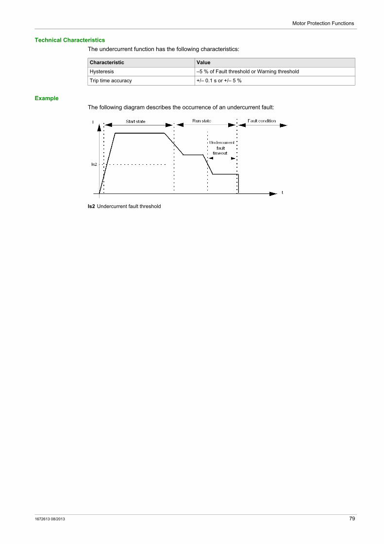
Motor Protection Functions
Technical Characteristics
The undercurrent function has the following characteristics:
Example
The following diagram describes the occurrence of an undercurrent fault:
Is2 Undercurrent fault threshold
Characteristic Value
Hysteresis –5 % of Fault threshold or Warning threshold
Trip time accuracy +/– 0.1 s or +/– 5 %
1672613 08/2013 79

Motor Protection Functions
80 1672613 08/2013
TeSys U DTM for FDT Container
Motor Control Functions
1672613 08/2013
Motor Control Functions
Chapter 4Motor Control Functions
Overview
This chapter describes the TeSys U starter-controller’s operating states, which determine the operating modes, and the fault reset mode (manual, remote, automatic).
What Is in This Chapter?
This chapter contains the following topics:
Topic Page
Operating States 82
Start Cycle 84
Logic Output Assignment 85
Recovery Mode 87
Reflex Stop Functions 88
Warning Management 90
Detected Fault Management 91
Clear Commands 94
1672613 08/2013 81
Motor Control Functions
Operating States
Introduction
The TeSys U starter-controller responds to the state of the motor and provides control, monitoring, and protection functions appropriate to each of the motor’s operating states. A motor can have many operating states. Some operating states are persistent while others are transitional.
A motor’s primary operating states are:
Operating State Status Parameter Description
Ready System Ready = 1Motor starting = 0Motor running = 0
The motor is stopped. The TeSys U starter-controller detects no fault, and is ready to start.
Not Ready System Ready = 0Motor starting = 0Motor running = 0
The motor is stopped. The TeSys U starter-controller detects a fault.
Start System Ready = 1Motor starting = 1Motor running = 1
The motor starts. The TeSys U starter-controller detects that current has reached 10 % FLA, detects that current has not both crossed and re-crossed the long
start fault threshold, and continues to count down the long start fault timer.
Run System Ready = 1Motor starting = 0Motor running = 1
The motor is running. The TeSys U starter-controller detects that current has both crossed
and re-crossed the long start fault threshold before the TeSys U starter-controller fully counted down the long start fault timer.
82 1672613 08/2013
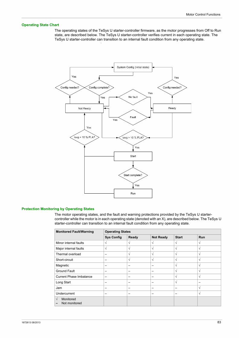
Motor Control Functions
Operating State Chart
The operating states of the TeSys U starter-controller firmware, as the motor progresses from Off to Run state, are described below. The TeSys U starter-controller verifies current in each operating state. The TeSys U starter-controller can transition to an internal fault condition from any operating state.
Protection Monitoring by Operating States
The motor operating states, and the fault and warning protections provided by the TeSys U starter-controller while the motor is in each operating state (denoted with an X), are described below. The TeSys U starter-controller can transition to an internal fault condition from any operating state.
Monitored Fault/Warning Operating States
Sys Config Ready Not Ready Start Run
Minor internal faults √ √ √ √ √
Major internal faults √ √ √ √ √
Thermal overload – √ √ √ √
Short-circuit – √ √ √ √
Magnetic – – – √ √
Ground Fault – – – √ √
Current Phase Imbalance – – – √ √
Long Start – – – √ –
Jam – – – – √
Undercurrent – – – – √
√ Monitored– Not monitored
1672613 08/2013 83
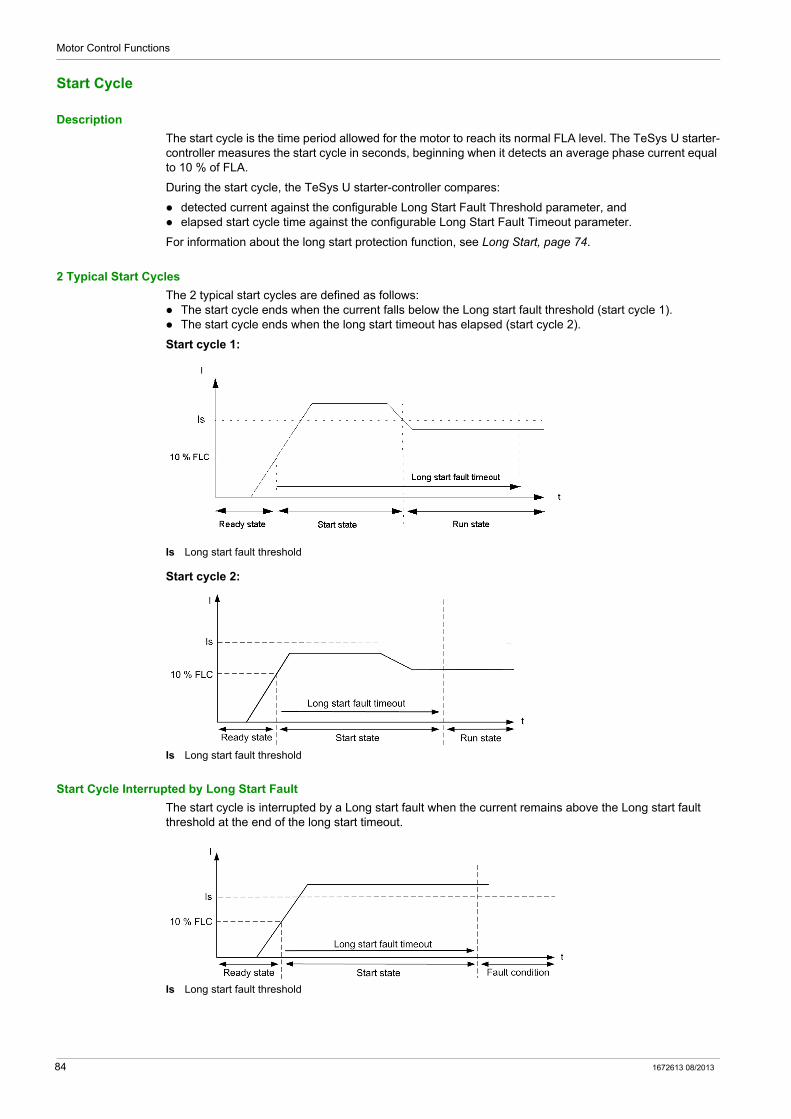
Motor Control Functions
Start Cycle
Description
The start cycle is the time period allowed for the motor to reach its normal FLA level. The TeSys U starter-controller measures the start cycle in seconds, beginning when it detects an average phase current equal to 10 % of FLA.
During the start cycle, the TeSys U starter-controller compares:
detected current against the configurable Long Start Fault Threshold parameter, and elapsed start cycle time against the configurable Long Start Fault Timeout parameter.
For information about the long start protection function, see Long Start, page 74.
2 Typical Start Cycles
The 2 typical start cycles are defined as follows: The start cycle ends when the current falls below the Long start fault threshold (start cycle 1). The start cycle ends when the long start timeout has elapsed (start cycle 2).
Start cycle 1:
Is Long start fault threshold
Start cycle 2:
Is Long start fault threshold
Start Cycle Interrupted by Long Start Fault
The start cycle is interrupted by a Long start fault when the current remains above the Long start fault threshold at the end of the long start timeout.
Is Long start fault threshold
84 1672613 08/2013
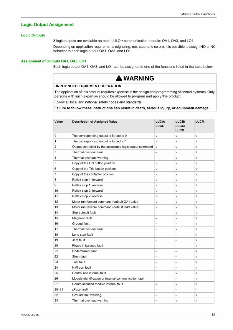
Motor Control Functions
Logic Output Assignment
Logic Outputs
3 logic outputs are available on each LULC•• communication module: OA1, OA3, and LO1.
Depending on application requirements (signaling, run, stop, and so on), it is possible to assign NO or NC behavior to each logic output OA1, OA3, and LO1.
Assignment of Outputs OA1, OA3, LO1
Each logic output OA1, OA3, and LO1 can be assigned to one of the functions listed in the table below.
WARNINGUNINTENDED EQUIPMENT OPERATION
The application of this product requires expertise in the design and programming of control systems. Only persons with such expertise should be allowed to program and apply this product.
Follow all local and national safety codes and standards.
Failure to follow these instructions can result in death, serious injury, or equipment damage.
Value Description of Assigned Value LUCA/LUCL
LUCB/LUCC/LUCD
LUCM
0 The corresponding output is forced to 0 √ √ √
1 The corresponding output is forced to 1 √ √ √
2 Output controlled by the associated logic output command √ √ √
3 Thermal overload fault – √ √
4 Thermal overload warning – √ √
5 Copy of the ON button position √ √ √
6 Copy of the Trip button position √ √ √
7 Copy of the contactor position √ √ √
8 Reflex stop 1: forward √ √ √
9 Reflex stop 1: reverse √ √ √
10 Reflex stop 2: forward √ √ √
11 Reflex stop 2: reverse √ √ √
12 Motor run forward command (default OA1 value) √ √ √
13 Motor run reverse command (default OA3 value) √ √ √
14 Short-circuit fault – √ √
15 Magnetic fault – √ √
16 Ground fault – – √
17 Thermal overload fault – √ √
18 Long start fault – – √
19 Jam fault – – √
20 Phase imbalance fault – – √
21 Undercurrent fault – – √
22 Shunt fault – – √
23 Test fault – – √
24 HMI port fault – – √
25 Control unit internal fault – √ √
26 Module identification or internal communication fault – – √
27 Communication module internal fault √ √ √
28–31 (Reserved) – – –
32 Ground fault warning – – √
33 Thermal overload warning – √ √
1672613 08/2013 85
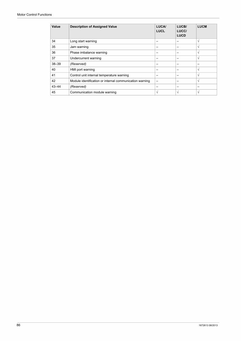
Motor Control Functions
34 Long start warning – – √
35 Jam warning – – √
36 Phase imbalance warning – – √
37 Undercurrent warning – – √
38–39 (Reserved) – – –
40 HMI port warning – – √
41 Control unit internal temperature warning – – √
42 Module identification or internal communication warning – – √
43–44 (Reserved) – – –
45 Communication module warning √ √ √
Value Description of Assigned Value LUCA/LUCL
LUCB/LUCC/LUCD
LUCM
86 1672613 08/2013
Motor Control Functions
Recovery Mode
Definition
If you use the Run forward and Run reverse command bits to control outputs OA1–OA3, enabling the recovery mode allows you to lock the motor and prevent it restarting following the occurrence of certain events: Loss followed by restoration of 24 Vdc (outputs OA1–OA3). Change in position of rotary knob on power base followed by return to ON position.
When one of these events occurs, command bits Run forward and Run reverse (and outputs OA1–OA3) are forced to 0 automatically. After these events have disappeared, control of the motor can be restored by resetting the Run command before sending a new Run command.
WARNINGAUTOMATIC RESTART OF THE MOTOR
Cyclic writing to command bits (for example, an LUFP• gateway in its predefined configuration) must be used with caution.
If the recovery mode is disabled, the application program must request that the command bits Run forward and Run reverse are written to 0.
Otherwise, the motor will restart automatically when the 24 Vdc is restored or when the rotary knob is turned to ON position.
Failure to follow these instructions can result in death, serious injury, or equipment damage.
1672613 08/2013 87
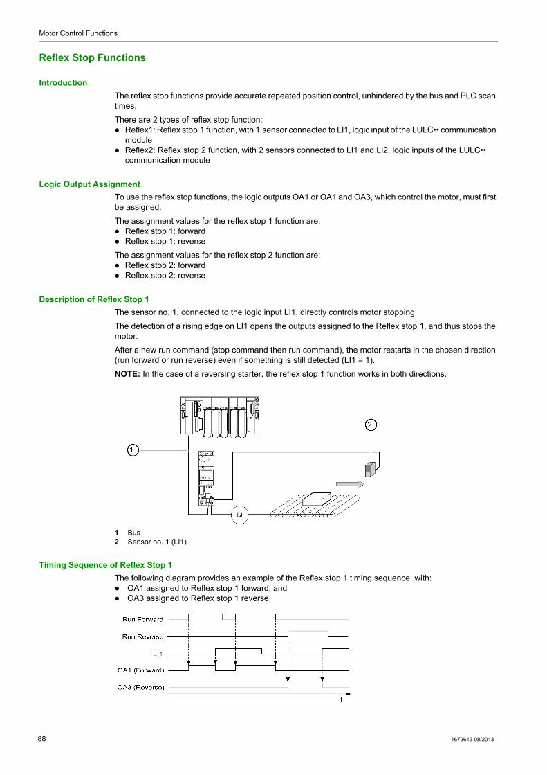
Motor Control Functions
Reflex Stop Functions
Introduction
The reflex stop functions provide accurate repeated position control, unhindered by the bus and PLC scan times.
There are 2 types of reflex stop function: Reflex1: Reflex stop 1 function, with 1 sensor connected to LI1, logic input of the LULC•• communication
module Reflex2: Reflex stop 2 function, with 2 sensors connected to LI1 and LI2, logic inputs of the LULC••
communication module
Logic Output Assignment
To use the reflex stop functions, the logic outputs OA1 or OA1 and OA3, which control the motor, must first be assigned.
The assignment values for the reflex stop 1 function are: Reflex stop 1: forward Reflex stop 1: reverse
The assignment values for the reflex stop 2 function are: Reflex stop 2: forward Reflex stop 2: reverse
Description of Reflex Stop 1
The sensor no. 1, connected to the logic input LI1, directly controls motor stopping.
The detection of a rising edge on LI1 opens the outputs assigned to the Reflex stop 1, and thus stops the motor.
After a new run command (stop command then run command), the motor restarts in the chosen direction (run forward or run reverse) even if something is still detected (LI1 = 1).
NOTE: In the case of a reversing starter, the reflex stop 1 function works in both directions.
1 Bus2 Sensor no. 1 (LI1)
Timing Sequence of Reflex Stop 1
The following diagram provides an example of the Reflex stop 1 timing sequence, with: OA1 assigned to Reflex stop 1 forward, and OA3 assigned to Reflex stop 1 reverse.
88 1672613 08/2013

Motor Control Functions
Description of Reflex Stop 2
The sensor no. 1 is connected to the logic input LI1. The detection of a rising edge on LI1 opens the output assigned to Reflex stop 2: forward.
The sensor no. 2 is connected to the logic input LI2. The detection of a rising edge on LI2 opens the output assigned to Reflex stop 2: reverse.
After a new run command (stop command then run command), the motor restarts in the chosen direction (run forward or run reverse) even if something is still detected (LI1 or LI2 = 1).
NOTE: Sensor no. 2 (LI2) does not affect forward mode and sensor no. 1 (LI1) does not affect reverse mode.
1 Bus2 Sensor no. 1 (LI1)3 Sensor no. 2 (LI2)
Timing Sequence of Reflex Stop 2
The following diagram provides an example of the Reflex stop 2 timing sequence, with: OA1 assigned to Reflex stop 2 forward, and OA3 assigned to Reflex stop 2 reverse.
1672613 08/2013 89
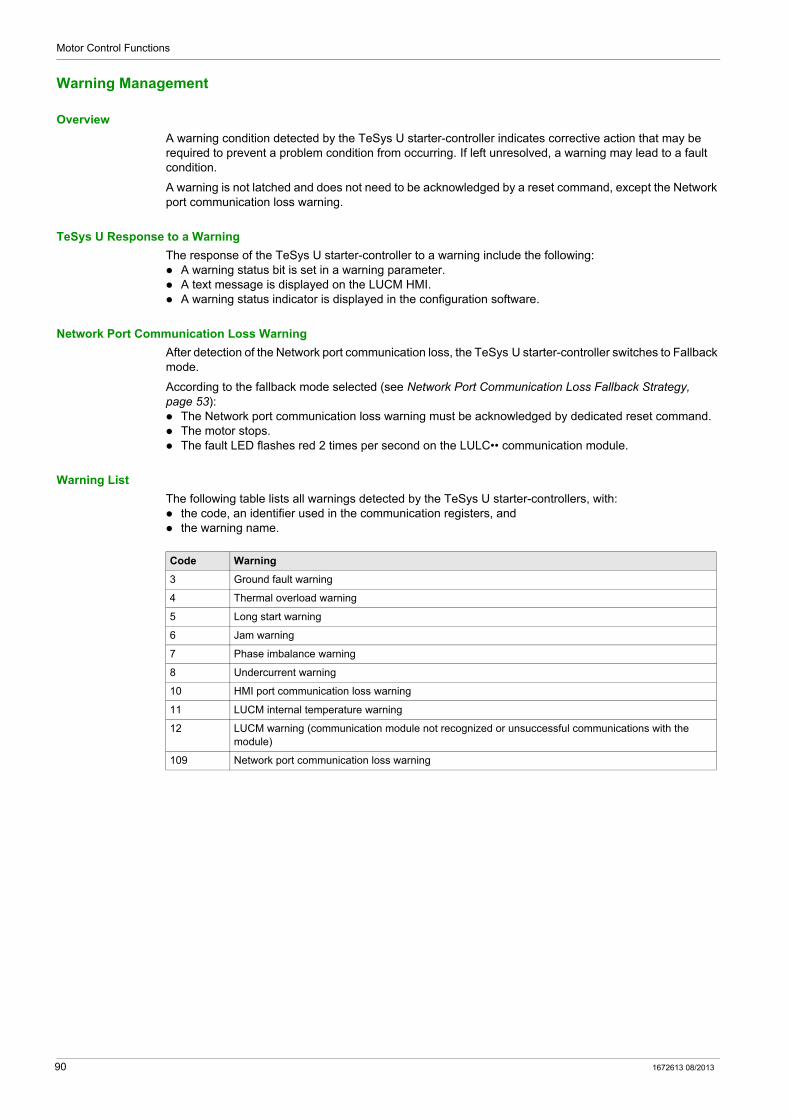
Motor Control Functions
Warning Management
Overview
A warning condition detected by the TeSys U starter-controller indicates corrective action that may be required to prevent a problem condition from occurring. If left unresolved, a warning may lead to a fault condition.
A warning is not latched and does not need to be acknowledged by a reset command, except the Network port communication loss warning.
TeSys U Response to a Warning
The response of the TeSys U starter-controller to a warning include the following: A warning status bit is set in a warning parameter. A text message is displayed on the LUCM HMI. A warning status indicator is displayed in the configuration software.
Network Port Communication Loss Warning
After detection of the Network port communication loss, the TeSys U starter-controller switches to Fallback mode.
According to the fallback mode selected (see Network Port Communication Loss Fallback Strategy, page 53): The Network port communication loss warning must be acknowledged by dedicated reset command. The motor stops. The fault LED flashes red 2 times per second on the LULC•• communication module.
Warning List
The following table lists all warnings detected by the TeSys U starter-controllers, with: the code, an identifier used in the communication registers, and the warning name.
Code Warning
3 Ground fault warning
4 Thermal overload warning
5 Long start warning
6 Jam warning
7 Phase imbalance warning
8 Undercurrent warning
10 HMI port communication loss warning
11 LUCM internal temperature warning
12 LUCM warning (communication module not recognized or unsuccessful communications with the module)
109 Network port communication loss warning
90 1672613 08/2013
Motor Control Functions
Detected Fault Management
Overview
When the TeSys U starter-controller detects a fault condition and activates the appropriate response, the fault becomes latched. It remains latched, even if the underlying fault condition is eliminated, until acknowledged by a reset command.
TeSys U Response to a Detected Fault
Responses of the TeSys U starter-controller after detection of a fault include the following: The motor stops by either Trip or Drop-out: Trip: the breaker trips Drop-out: the contactor opens
The fault LED is On on the LULC•• communication module. A fault status bit is set in a fault parameter. A text message is displayed on LUCM HMI. A fault status indicator is displayed in the configuration software, if connected.
Reset Modes
The user can select the fault reset mode from 3 modes: manual (by default) remote automatic
NOTE:
The Automatic and Remote fault reset modes are available only on a TeSys U starter-controller: with an LUCB, LUCC, or LUCD control unit in association with an LUFDA•• module, or with an LUCB, LUCC, LUCD or LUCM control unit in association with an LULC•• communication
module.
Reset Actions
According to the fault reset mode selected and the type of detected fault, the reset action to acknowledge a detected fault can be one of the following: A manual action: reset by manual action on the power base handle A remote action: reset by Reset command through the communication network Action on the ENT key on the LUCM control unit Power cycle of the TeSys U starter-controller
An automatic action: automatic reset after a timeout set by the Thermal Overload Fault Reset Timeout parameter
Detected Fault List
The following tables list all faults detected by the TeSys U starter-controllers, with the fault code, an identifier used in the communication registers the history registers (except for internal faults or Shunt Trip fault)
the fault name
And, according to the Fault reset mode selected (M=Manual, R=Remote, or A=Automatic): the TeSys U response after detection of the fault, and the reset action to be performed by the user to acknowledge the fault.
1672613 08/2013 91
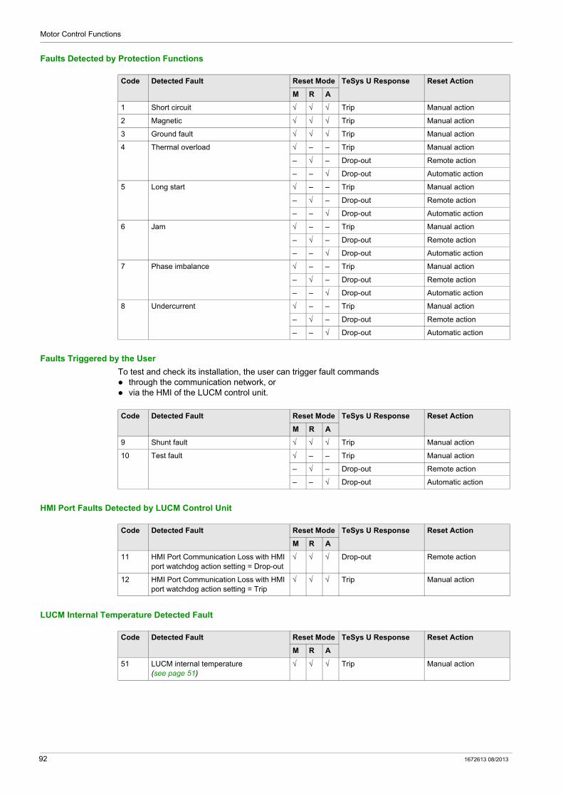
Motor Control Functions
Faults Detected by Protection Functions
Faults Triggered by the User
To test and check its installation, the user can trigger fault commands through the communication network, or via the HMI of the LUCM control unit.
HMI Port Faults Detected by LUCM Control Unit
LUCM Internal Temperature Detected Fault
Code Detected Fault Reset Mode TeSys U Response Reset Action
M R A
1 Short circuit √ √ √ Trip Manual action
2 Magnetic √ √ √ Trip Manual action
3 Ground fault √ √ √ Trip Manual action
4 Thermal overload √ – – Trip Manual action
– √ – Drop-out Remote action
– – √ Drop-out Automatic action
5 Long start √ – – Trip Manual action
– √ – Drop-out Remote action
– – √ Drop-out Automatic action
6 Jam √ – – Trip Manual action
– √ – Drop-out Remote action
– – √ Drop-out Automatic action
7 Phase imbalance √ – – Trip Manual action
– √ – Drop-out Remote action
– – √ Drop-out Automatic action
8 Undercurrent √ – – Trip Manual action
– √ – Drop-out Remote action
– – √ Drop-out Automatic action
Code Detected Fault Reset Mode TeSys U Response Reset Action
M R A
9 Shunt fault √ √ √ Trip Manual action
10 Test fault √ – – Trip Manual action
– √ – Drop-out Remote action
– – √ Drop-out Automatic action
Code Detected Fault Reset Mode TeSys U Response Reset Action
M R A
11 HMI Port Communication Loss with HMI port watchdog action setting = Drop-out
√ √ √ Drop-out Remote action
12 HMI Port Communication Loss with HMI port watchdog action setting = Trip
√ √ √ Trip Manual action
Code Detected Fault Reset Mode TeSys U Response Reset Action
M R A
51 LUCM internal temperature (see page 51)
√ √ √ Trip Manual action
92 1672613 08/2013

Motor Control Functions
Internal Faults Detected by LUCM Control Unit
For more information about internal faults, refer to TeSys U internal faults (see page 50).
Wiring Faults Detected by LUCM Control Unit
Communication Module Faults
Code Detected Fault Reset Mode TeSys U Response Reset Action
M R A
52 ASIC1 read-after-write fault √ √ √ Trip Manual action
53 ASIC1 initialize check fault √ √ √ Trip Manual action
54 ASIC2 watchdog or ASIC2 DTH over temperature
√ √ √ Trip Manual action
55 Stack overflow fault √ √ √ Trip Manual action
56 RAM fault √ √ √ Trip Manual action
57 ROM (flash) fault √ √ √ Trip Manual action
58 Hardware watchdog √ √ √ Trip Manual action
59 Current detected while OFF √ √ √ Trip Manual action
64 FRAM strings checksum fault √ √ √ Trip Manual action
– EEPROM checksum fault √ √ √ Trip Manual action
– Current sensor loss fault √ √ √ Trip Manual action
Code Detected Fault Reset Mode TeSys U Response Reset Action
M R A
60 Phase configuration error √ √ √ Trip Manual action
61 Undetected base change √ √ √ Trip Manual action
62 A2 missing √ √ √ Trip Manual action
63 A1 overvoltage √ √ √ Trip Manual action
Code Detected Fault Reset Mode TeSys U Response Reset Action
M R A
100 Write-to-EEPROM fault √ √ √ Drop-out Power cycle
101 Communication fault with LUCM control unit
√ √ √ Drop-out Power cycle
102 Checksum-on-EEPROM fault √ √ √ Drop-out Remote action
104 EEPROM configuration fault √ √ √ Drop-out Remote action
1672613 08/2013 93
Motor Control Functions
Clear Commands
Overview
Clear commands allow the user to clear specific categories of TeSys U parameters: Clear all parameters Clear the statistics
The Clear commands can be delivered from: a PC running SoMove with the TeSys U DTM the LUCM control unit a PLC via the network port
Clear All Command
If you want to change the configuration of the TeSys U starter-controller, you may want to clear all existing parameters in order to return to factory settings before setting new parameters for TeSys U.
The Clear All Command forces TeSys U to enter configuration mode. A power cycle is performed to restart correctly in this mode. This enables TeSys U to pick up the new values for the cleared parameters.
NOTE: When you clear all parameters, static characteristics are also lost. Only the LUCM internal temperature max parameter is not cleared after a clear all command.
Clear Statistics Command
Statistics parameters are cleared without the TeSys U starter-controller being forced into configuration mode. Static characteristics and settings are preserved.
The LUCM internal temperature max parameter is the only statistics parameter that is not cleared after a clear statistics command.
94 1672613 08/2013
TeSys U DTM for FDT Container
Communication Functions
1672613 08/2013
Communication Functions
Chapter 5Communication Functions
Overview
This chapter presents the general settings available in the TeSys U DTM for each communication protocol, and the configuration of the HMI port on the LUCM control unit.
What Is in This Chapter?
This chapter contains the following topics:
Topic Page
Configuration of the LULC•• Network Port 96
Configuration of the Tesys U LUCM HMI Port 98
1672613 08/2013 95
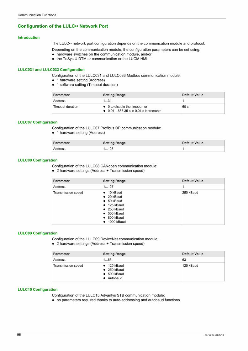
Communication Functions
Configuration of the LULC•• Network Port
Introduction
The LULC•• network port configuration depends on the communication module and protocol.
Depending on the communication module, the configuration parameters can be set using: hardware switches on the communication module, and/or the TeSys U DTM or communication or the LUCM HMI.
LULC031 and LULC033 Configuration
Configuration of the LULC031 and LULC033 Modbus communication module: 1 hardware setting (Address) 1 software setting (Timeout duration)
LULC07 Configuration
Configuration of the LULC07 Profibus DP communication module: 1 hardware setting (Address)
LULC08 Configuration
Configuration of the LULC08 CANopen communication module: 2 hardware settings (Address + Transmission speed)
LULC09 Configuration
Configuration of the LULC09 DeviceNet communication module: 2 hardware settings (Address + Transmission speed)
LULC15 Configuration
Configuration of the LULC15 Advantys STB communication module: no parameters required thanks to auto-addressing and autobaud functions.
Parameter Setting Range Default Value
Address 1...31 1
Timeout duration 0 to disable the timeout, or 0.01…655.35 s in 0.01 s increments
60 s
Parameter Setting Range Default Value
Address 1...125 1
Parameter Setting Range Default Value
Address 1...127 1
Transmission speed 10 kBaud 20 kBaud 50 kBaud 125 kBaud 250 kBaud 500 kBaud 800 kBaud 1000 kBaud
250 kBaud
Parameter Setting Range Default Value
Address 1...63 63
Transmission speed 125 kBaud 250 kBaud 500 kBaud Autobaud
125 kBaud
96 1672613 08/2013

Communication Functions
Network Port Fallback Setting
Network port fallback setting is used to adjust the fallback mode in case of a loss of communication with the PLC. This setting must be configured whatever the protocol. Refer to Network Port Communication Loss Fallback Strategy (see page 53).
1672613 08/2013 97
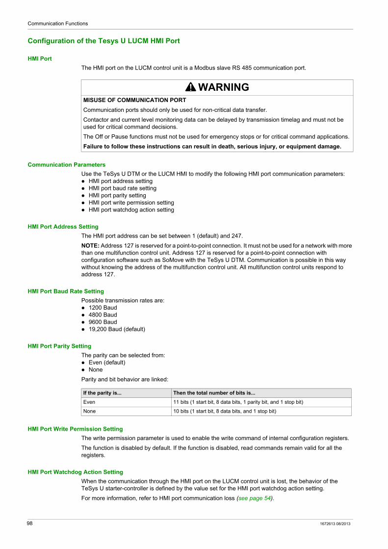
Communication Functions
Configuration of the Tesys U LUCM HMI Port
HMI Port
The HMI port on the LUCM control unit is a Modbus slave RS 485 communication port.
Communication Parameters
Use the TeSys U DTM or the LUCM HMI to modify the following HMI port communication parameters: HMI port address setting HMI port baud rate setting HMI port parity setting HMI port write permission setting HMI port watchdog action setting
HMI Port Address Setting
The HMI port address can be set between 1 (default) and 247.
NOTE: Address 127 is reserved for a point-to-point connection. It must not be used for a network with more than one multifunction control unit. Address 127 is reserved for a point-to-point connection with configuration software such as SoMove with the TeSys U DTM. Communication is possible in this way without knowing the address of the multifunction control unit. All multifunction control units respond to address 127.
HMI Port Baud Rate Setting
Possible transmission rates are: 1200 Baud 4800 Baud 9600 Baud 19,200 Baud (default)
HMI Port Parity Setting
The parity can be selected from: Even (default) None
Parity and bit behavior are linked:
HMI Port Write Permission Setting
The write permission parameter is used to enable the write command of internal configuration registers.
The function is disabled by default. If the function is disabled, read commands remain valid for all the registers.
HMI Port Watchdog Action Setting
When the communication through the HMI port on the LUCM control unit is lost, the behavior of the TeSys U starter-controller is defined by the value set for the HMI port watchdog action setting.
For more information, refer to HMI port communication loss (see page 54).
WARNINGMISUSE OF COMMUNICATION PORT
Communication ports should only be used for non-critical data transfer.
Contactor and current level monitoring data can be delayed by transmission timelag and must not be used for critical command decisions.
The Off or Pause functions must not be used for emergency stops or for critical command applications.
Failure to follow these instructions can result in death, serious injury, or equipment damage.
If the parity is... Then the total number of bits is...
Even 11 bits (1 start bit, 8 data bits, 1 parity bit, and 1 stop bit)
None 10 bits (1 start bit, 8 data bits, and 1 stop bit)
98 1672613 08/2013
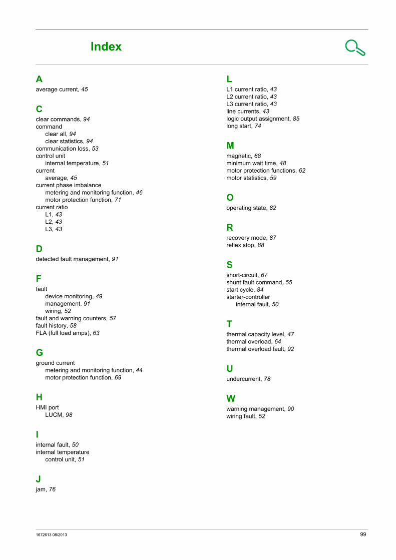
TeSys U DTM for FDT Container
Index
1672613 08/2013
Index
Aaverage current, 45
Cclear commands, 94command
clear all, 94clear statistics, 94
communication loss, 53control unit
internal temperature, 51current
average, 45current phase imbalance
metering and monitoring function, 46motor protection function, 71
current ratioL1, 43L2, 43L3, 43
Ddetected fault management, 91
Ffault
device monitoring, 49management, 91wiring, 52
fault and warning counters, 57fault history, 58FLA (full load amps), 63
Gground current
metering and monitoring function, 44motor protection function, 69
HHMI port
LUCM, 98
Iinternal fault, 50internal temperature
control unit, 51
Jjam, 76
1672613 08/2013
LL1 current ratio, 43L2 current ratio, 43L3 current ratio, 43line currents, 43logic output assignment, 85long start, 74
Mmagnetic, 68minimum wait time, 48motor protection functions, 62motor statistics, 59
Ooperating state, 82
Rrecovery mode, 87reflex stop, 88
Sshort-circuit, 67shunt fault command, 55start cycle, 84starter-controller
internal fault, 50
Tthermal capacity level, 47thermal overload, 64thermal overload fault, 92
Uundercurrent, 78
Wwarning management, 90wiring fault, 52
99

As standards, specifications and designs change from time to time, please ask for confirmationof the information given in this publication.
1672613
Schneider Electric Industries SAS35, rue Joseph MonierCS30323F - 92506 Rueil Malmaison Cedex
www.schneider-electric.com 08/2013