tetris w rev - arfit€¦ · tetris w rev 38÷616 kw general liquid refrigerators and high...
TRANSCRIPT

Tetris W Rev38÷616 kW
GeneralLiquid refrigerators and high efficiency heat pumps with water source, with scroll compressors in R410A for indoor installation
ConfigurationsBasic: high efficiency chillerOH: high efficiency non-reversible heat pumpHPW: high efficiency water-side reversible heat pumpHP: high efficiency refrigerator-side reversible heat pumpLC: condenserless set-upLC/HP: reversible condenserless set-up
Strengths ► High efficiency unit ► The widest range of capacities and versions ► Hydraulic modules also integrated with buffer tank
► Three types of pumps: standard, oversize and for high percentages of glycol (up to 50% e.g.)
► Bluethink: advanced control with integrated web server
► Multilogic: management of multiple unit sys-tems
► Flowzer: system with variable water flow rate ► Blueye®: supervision system


1
One machine, many solutions 3Tetris W Rev
Description of accessories 8Refrigerant circuit accessories 8Hydraulic circuit accessories 10Electrical accessories 14Other accessories 18
Technical specifications 20Tetris W Rev 20Tetris W Rev HP 24Tetris W Rev OH 28Tetris W Rev HPW 32Tetris W Rev LC 36Tetris W Rev LC/HP 40
Electrical specifications 44
Pump data 46
Flow rate ranges of heat exchangers 47
Operating limits 50Tetris W Rev - Tetris W Rev HP - Tetris W Rev OH - Tetris W Rev HPW 50Tetris W Rev LC - Tetris W Rev LC/HP 51
Noise levels 52
Configurations that are not possible 54
Tables of dimensions 55
Installation advice 58Water characteristics 58Glycol mixtures 58Minimum water content in the system 59Installation site 59

2

3
ONE MACHINE, MANY SOLUTIONSTetris W Rev is the result of a platform developed with modular logic, which allows a highly flexible and configur-able product to be obtained.Since this is an indoor unit, the structure has been de-signed to be as compact as possible: its width of 875mm and height of 1,880mm allow even the largest model to pass easily through the doors of the technical rooms. Fur-thermore, the unit does not require manifolds for connec-tion of the main heat exchangers and so also the installa-tion space is further reduced.Tetris W Rev offers a wide range of capacities and con-figurations: the range covers 31 models divided between single circuit units from 38 to 385kW and dual circuit units from 160 to 618kW. In the capacity range between 163 and 385kW, the customer can choose between the more compact single circuit units and the dual circuit units with higher ESEER values.
Extreme flexibility is also given for combination with dif-ferent types of sources: evaporative tower, dry-cooler, well, geothermal probe or remote condenser, according to the most suitable and expedient source. Depending on the choice and the type of application, the unit can be com-pleted with the available accessories.
Built-in hydraulic modules
Tetris W Rev can be equipped with various set-ups of hy-draulic modules, designed to have the flexibility required to cover all possible applications. One or two pumps (one as backup to the other) can be requested respectively for the user-side and source-side circuits and also (in the case of /DC version) the heat recovery-side circuit, up to a maximum of four pumps. Also, in combination with the user-side pumps, a buffer tank can be inserted inside the structure.
Each hydraulic module can be coupled with three different types of pump:• standard, for available discharge heads of about 120kPa• oversize, for available discharge heads of about 200kPa• for fluids containing up to 50% glycolThe user-side hydraulic module can also be fitted with one of the Flowzer options, which allow you to make hydronic systems with constant flow rate, constant pressure or with variable flow rate user-side circuit, thanks to the use of inverter technology combined with advanced control. For further details, please refer to the description of Flowzer accessories in the "Hydraulic circuit accessories" chapter
The 4 forms of heat pumpTetris W Rev offers four different heat pump set-ups to suit all types of application.Tetris W Rev OH is a high efficiency non-reversible heat pump that is suitable for all applications in which the user needs only heating production. In this set-up, the unit is optimized to operate in heating mode only.Tetris W Rev HPW is a high efficiency water-side revers-ible heat pump that is suitable for applications in which the user-side circuit and the source-side circuit can be ex-changed with each other. Compared to other solutions, water side reversal has the advantage of keeping the heat exchangers in counter-flow in both chiller and heat pump operating modes.To make the cycle reversal, the fitter must install a system of valves that will allow the two circuits to be exchanged.If the seasonal mode change is carried out via remote signal or BMS, Tetris W Rev HPW can control motor-driven reversing valves (not supplied) so as to make this opera-tion fully automatic.Tetris W Rev /HP is a high efficiency refrigerator-side reversible heat pump: this version always guarantees sep-aration between source and user fluids, thus also allow-ing different pumps to be used on the various hydronic circuits, does not require external reversing valves and makes the installation operations easier.Tetris W Rev LC/HP is a reversible condenserless unit that, combined with a remote reversible condenser, allows the hydronic part to be installed in a technical room inside the building and the ventilation part to be installed outside or on the roof. This allows greater flexibility on dimensions and noisiness of the ventilation part and the advantage of not being required to add glycol to the water of the us-er-side circuit since it is completely indoors.
4
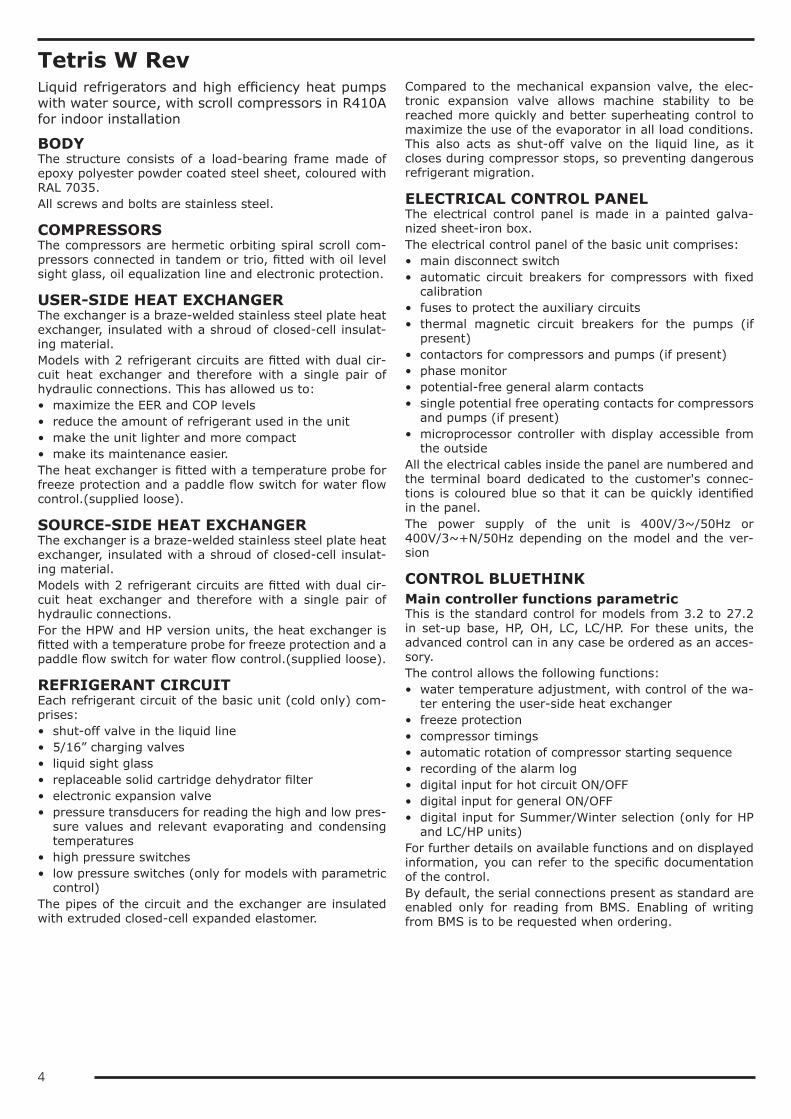
Tetris W RevLiquid refrigerators and high efficiency heat pumps with water source, with scroll compressors in R410A for indoor installation
BODYThe structure consists of a load-bearing frame made of epoxy polyester powder coated steel sheet, coloured with RAL 7035.All screws and bolts are stainless steel.
COMPRESSORSThe compressors are hermetic orbiting spiral scroll com-pressors connected in tandem or trio, fitted with oil level sight glass, oil equalization line and electronic protection.
USER-SIDE HEAT EXCHANGERThe exchanger is a braze-welded stainless steel plate heat exchanger, insulated with a shroud of closed-cell insulat-ing material.Models with 2 refrigerant circuits are fitted with dual cir-cuit heat exchanger and therefore with a single pair of hydraulic connections. This has allowed us to:• maximize the EER and COP levels• reduce the amount of refrigerant used in the unit• make the unit lighter and more compact• make its maintenance easier.The heat exchanger is fitted with a temperature probe for freeze protection and a paddle flow switch for water flow control.(supplied loose).
SOURCE-SIDE HEAT EXCHANGERThe exchanger is a braze-welded stainless steel plate heat exchanger, insulated with a shroud of closed-cell insulat-ing material.Models with 2 refrigerant circuits are fitted with dual cir-cuit heat exchanger and therefore with a single pair of hydraulic connections.For the HPW and HP version units, the heat exchanger is fitted with a temperature probe for freeze protection and a paddle flow switch for water flow control.(supplied loose).
REFRIGERANT CIRCUITEach refrigerant circuit of the basic unit (cold only) com-prises:• shut-off valve in the liquid line• 5/16” charging valves• liquid sight glass• replaceable solid cartridge dehydrator filter• electronic expansion valve• pressure transducers for reading the high and low pres-
sure values and relevant evaporating and condensing temperatures
• high pressure switches• low pressure switches (only for models with parametric
control)The pipes of the circuit and the exchanger are insulated with extruded closed-cell expanded elastomer.
Compared to the mechanical expansion valve, the elec-tronic expansion valve allows machine stability to be reached more quickly and better superheating control to maximize the use of the evaporator in all load conditions. This also acts as shut-off valve on the liquid line, as it closes during compressor stops, so preventing dangerous refrigerant migration.
ELECTRICAL CONTROL PANELThe electrical control panel is made in a painted galva-nized sheet-iron box.The electrical control panel of the basic unit comprises:• main disconnect switch• automatic circuit breakers for compressors with fixed
calibration• fuses to protect the auxiliary circuits• thermal magnetic circuit breakers for the pumps (if
present)• contactors for compressors and pumps (if present)• phase monitor• potential-free general alarm contacts• single potential free operating contacts for compressors
and pumps (if present)• microprocessor controller with display accessible from
the outsideAll the electrical cables inside the panel are numbered and the terminal board dedicated to the customer's connec-tions is coloured blue so that it can be quickly identified in the panel.The power supply of the unit is 400V/3~/50Hz or 400V/3~+N/50Hz depending on the model and the ver-sion
CONTROL BLUETHINKMain controller functions parametricThis is the standard control for models from 3.2 to 27.2 in set-up base, HP, OH, LC, LC/HP. For these units, the advanced control can in any case be ordered as an acces-sory.The control allows the following functions:• water temperature adjustment, with control of the wa-
ter entering the user-side heat exchanger• freeze protection• compressor timings• automatic rotation of compressor starting sequence• recording of the alarm log• digital input for hot circuit ON/OFF• digital input for general ON/OFF• digital input for Summer/Winter selection (only for HP
and LC/HP units)For further details on available functions and on displayed information, you can refer to the specific documentation of the control.By default, the serial connections present as standard are enabled only for reading from BMS. Enabling of writing from BMS is to be requested when ordering.

5
Main controller functions advancedThis is the standard control for all models in HPW set-up and all models with more than two compressors.The control allows the following functions:• water temperature adjustment, with control of the wa-
ter entering the user-side heat exchanger• freeze protection• compressor timings• automatic rotation of compressor starting sequence• recording of the log of all machine inputs, outputs and
states• automatic rotation of compressor starting sequence• recording of the alarm log• digital input for hot circuit ON/OFF• Ethernet serial port with Modbus protocol and integrat-
ed web server preloaded web page• digital input for general ON/OFF• digital input for Summer/Winter selection (only for HP,
HPW and LC/HP units)For further details on available functions and on displayed information, you can refer to the specific documentation of the control.By default, the serial connections present as standard are enabled only for reading from BMS. Enabling of writing from BMS is to be requested when ordering.
Main functions of the webserver (only for units with advanced control)As standard, the Bluethink controller integrates a web-server with a preloaded web page that is accessed via password.The web page allows the following functions to be carried out (some of these are available only for users with ad-vanced level rights):• display of the main functions of the unit such as unit
serial n°, size, refrigerant• display of the general status of the machine: water in-
let and outlet temperatures, external air temperature, mode (chiller or heat pump), evaporating and condens-ing pressures, suction and discharge temperatures
• display of the status of compressors, pumps, expansion valves
• display in real time of the graphs of the main quantities• display of the graphs of logged quantities• display of alarm log• management of users on several levels• remote ON/OFF• remote set point change• remote time band change• remote summer winter mode selection
Human-Machine InterfaceThe control has a graphic display that allows the following information to be displayed:• water inlet and outlet temperature• set temperature and differential set points• description of alarms• hour meter of operation and number of start-ups of the
unit, the compressors and the pumps (if present)• high and low pressure values, and relevant condensing
and evaporating temperatures• external air temperature• superheating at compressor suction.
Management of defrost cycles (only for LC/HP versions)For defrost management, the control of the unit uses a sliding intervention threshold, depending on the pressures inside the unit and the external air temperature. By put-ting together all this information, the control can identify the presence of ice on the coil and activates the defrosting sequence only when necessary, so as to maximize the en-ergy efficiency of the unit.Sliding management of the defrost threshold ensures that, as the absolute humidity of outdoor air decreases, the fre-quency of the defrost cycles gradually decreases because they are carried out only when the ice formed on the coil actually penalizes performance.The defrost cycle is fully automatic and is carried out using a patented defrost system (patent n° 1335232): during the initial stage, a defrost is carried out by cycle reversal with fans stopped. When the frost on the coil has melted sufficiently, reverse ventilation is activated, that is, with air flow in the opposite direction to that of normal oper-ation, so as to facilitate the ejection of condensed water and detached ice. When the coil is clean, ventilation is reversed again and the unit resumes operation in heat pump mode.The combination of the sliding intervention threshold and the patented defrost system allows the number and dura-tion of defrost cycles to be optimized and reduced to the minimum.The above applies only when the unit is coupled to a re-mote condenser combined as per catalogue and supplied from the factory and when this is controlled by the internal unit.
CONTROLS AND SAFETY DEVICESAll the units are fitted with the following control and safety components:• high pressure switch with manual reset• high pressure safety device with automatic reset, for a
limited number of occurrences, managed by the con-troller
• low pressure safety device with automatic reset and limited tripping managed by the controller
• high pressure safety valve• antifreeze probe at outlet of each evaporator• compressor overtemperature protection• mechanical paddle flow switch (supplied loose)

6
TESTINGAll the units are factory-tested and supplied complete with oil and refrigerant.The LC and LC/HP version units are electrically tested. For on-site installation, in addition to the electrical and hy-draulic connections for the user part, it will be necessary to make the refrigerant connection to the remote heat ex-changer and charge with the correct refrigerant and oil charge.
PACKAGINGThe unit is made and shipped on a wooden pallet that al-lows the unit to be handled using a forklift truck.The unit is wrapped in transparent polyethylene stretch film.
VERSIONSIn the basic version, the unit is a high efficiency liquid chiller, but includes various types of set-up as an option so as to meet the requirements of all types of application.
OH: heat pump for heating onlyThe OH unit is a non-reversible heat pump.
HPW: heat pump with hydronic-side reversalThe HPW unit is a heat pump that includes cycle reversal on the hydronic side of the system via special 3-way or 4-way reversing valves outside the unit (not supplied).In addition to what is present in the basic version, the HPW set-up includes an OK signal in the terminal board for controlling the group of external reversing valves (not supplied).
HP: reversible heat pumpThe HP unit is a reversible heat pump with cycle reversal on the chiller side.In addition to what is present in the basic version, the HP set-up includes:• 4-way reversing valve• paddle flow switch for source-side water flow control
(supplied with the unit).
LC: condenserless unitThe LC unit is a condenserless unit and therefore, com-pared to the basic unit, is without the source-side heat exchanger and the refrigerant charge.The unit must be connected to a suitably sized remote heat exchanger.
LC/HP: reversible condenserless unitThe LC/HP unit is a reversible condenserless unit and therefore, compared to the HP unit, is without the source-side heat exchanger and the refrigerant charge. Compared to the HP unit, it has the suction separator in addition.The unit must be connected to a suitably sized remote heat exchanger. The heat exchanger must be suitable for operation as condenser and as evaporator and must be fit-ted with an expansion valve (with relevant bypass valve) sized for operation of the system in heat pump mode.
OPTIONS/DC: unit with recovery condenserIn addition to the set-up of a chiller only unit, /DC units include:• a heat recovery condenser for recovering 100% of the
condensation heat; the exchanger is a braze-welded plate heat exchanger
• temperature probe at the inlet of the heat recovery heat exchanger
• a liquid receiver for each refrigerant circuitThis set-up is not available for the OH, HPW, HP and LC/HP units.
/DS: unit with partial heat recoveryIn addition to the set-up of a chiller only unit, /DS units comprise (for each refrigerant circuit) a heat exchanger for partial recovery of condensation heat, placed in series with the source-side heat exchanger. The exchanger is a braze-welded plate heat exchanger.This option is also available for HPW, HP e LC/HP units, but in this case, in the installation, there must be provision for shutting off the heat recovery water circuit during opera-tion in heat pump mode to avoid taking power from the user-side heat exchanger.
/LN: low noise unitUnits in LN set-up are fully panelled with epoxy polyes-ter powder coated steel sheet panels coloured with RAL 7035 and lined with matting made of sound absorbing and soundproofing material.Example of non /LN unit
Example of /LN unit

7
HYDRAULIC MODULESAll the units can be equipped with hydraulic module in various combinations on the user side, on the source side and in combination with the total heat recovery heat ex-changer. Refer to the table of configurations that are not possible to check for availability of specific set-ups.Hydraulic modules with one pump have:• one pump• a gate valve on the delivery side of the pump• an expansion vesselHydraulic modules with two pumps have:• two pumps• a check valve on the delivery side of each pump• a gate valve on the outlet of the delivery manifold• an expansion vesselIn the version with 2 pumps, these are always with one on standby while the other is working. Switching over be-tween the pumps is automatic and is done by time (to balance the hours of operation of each one) or in the event of failure.Hydraulic modules with tank also have:• a gate valve at the inlet of the pump or the suction
manifold• a tank with drain valve and air valve
User-side hydraulic modulesThe hydraulic circuit inside the unit is fully insulated with closed-cell insulating material..The module can have the following configurations:• /1P: hydraulic module with one pump• /1PS: hydraulic module with one pump and buffer tank• /2P: hydraulic module with two pumps• /2PS: hydraulic module with two pumps and buffer tankAll the above-mentioned modules have pumps with stand-ard discharge head.The following are also available:modules /1PM, /1PMS, /2PM and /2PMS that have pumps with increased available discharge headmodules /1PG, /1PGS, /2PG and /2PGS that have pumps suitable for operating with glycol up to 50%
Source-side hydraulic modulesThe source side pumps are normally switched off and they are switched on a few seconds before the start of first compressor.When reaching the set point, a few seconds after switch-ing off the last compressor, the source side pumps are switched off again.The hydraulic circuit inside the unit is fully insulated with closed-cell insulating material. (only for units in HP or HPW set-up).
The module can have the following configurations:• /1S: hydraulic module with one pump• /2S: hydraulic module with two pumpsAll the above-mentioned modules have pumps with stand-ard discharge head.The following are also available:modules /1SM and /2SM that have pumps with increased available discharge headmodules /1SG and /2SG that have pumps suitable for op-erating with glycol up to 50%
Total heat recovery-side hydraulic modulesThe hydraulic circuit inside the unit is fully insulated with closed-cell insulating material..The module can have the following configurations:• /1R: hydraulic module with one pump• /2R: hydraulic module with two pumpsAll the above-mentioned modules have pumps with stand-ard discharge head.The following are also available:modules /1RM and /2RM that have pumps with increased available discharge headmodules /1RG and /2RG that have pumps suitable for op-erating with glycol up to 50%

8
DESCRIPTION OF ACCESSORIESRefrigerant circuit accessoriesThe "(S)" symbol indicates that the option is present as standard in the unit, provided this is not in conflict with other selected accessories.
BC Capacitive backup battery for electronic expansion valveWhen the compressors stop, the controller always closes the electronic expansion valve to prevent dangerous refrigerant migration. The presence of the backup battery ensures that the electronic valve is kept in closed position even when there is no power supplyThis accessory uses a condenser, and not an ordinary battery, as energy storage: this allows it to be unaffected by the memory effect of normal batteries and eliminates its need for maintenance.
BT Backup battery for electronic expansion valveWhen the compressors stop, the controller always closes the electronic expansion valve to prevent dangerous refrigerant migration. The presence of the backup battery ensures that the electronic valve is kept in closed position even when there is no power supply
BK Brine KitThis accessory is compulsory if a water temperature set point lower than +3°C is used (if the unit is provided with double set point or variable set point, the lower set point is considered).The accessory consists of increased insulation and suitable sizing and calibration of some components.The inlet and outlet temperatures of the user-side exchanger must be given on ordering to allow correct set-ting of the alarm parameters and verification of the sizing of the expansion valve.The cooling set point can then be changed by the customer in an interval that, compared to the set point given on ordering, ranges from -1K up to the maximum temperature allowed by the above-stated operating limits.The unit will be optimized to work at the set point temperature given on ordering. For different set points, the cooling capacity provided and the level of efficiency of the machine could decrease and move away from these conditions.
DVS Double safety valveWith this accessory, instead of each individual safety valve per circuit, there is a "candelabrum" with two safety valves and a diverter valve for choosing the valve in operation. This allows the safety valves to be replaced without having to drain the machine and without having to stop it.
MAFR Pressure gaugesThe operating pressures of each circuit of the unit can be displayed on the control by accessing the relevant screens. Also, the machine can be fitted with pressure gauges (two for each circuit) installed in a clearly visible position. These allow reading in real time of the working pressures of the refrigerant gas on the low pressure side and on the high pressure side of each refrigerant circuit.
RIC Liquid receiverThe adoption of this accessory always guarantees correct feeding of the expansion valve even when the unit is subjected to wide external air temperature ranges.
RPP Refrigerant leak detector with automatic pump downWith this accessory, a refrigerant leak detector is placed inside each compressor compartment. Detection of a refrigerant leak is managed by the control through a specific alarm and display of a specific icon on the display of the control. For all the circuits of the unit, the alarm also starts the machine stopping procedure with pump down, confining all the refrigerant in the coils.The accessory includes the capacitive backup battery.The accessory can be applied only to units in LN or SLN set-up.
RPR Refrigerant leak detectorWith this accessory, a refrigerant leak detector is placed inside each compressor compartment. Detection of a refrigerant leak is managed by the controller through a specific alarm and display of a specific icon on the display of the controller. This alarm stops the unit.The accessory can be applied only to units in LN or SLN set-up.

9
RUB Compressor suction and delivery valvesThe valves situated on the delivery side and on the suction side of the compressors allow the compressor to be isolated from the rest of the refrigerant circuit, so making the maintenance operations quicker and less invasive
VTE Electronic expansion valve (S)The use of this component is particularly advisable on units operating in very variable heat load or operating mode conditions, as in the case of joint management of air conditioning and high temperature water produc-tion. The use of an electronic thermostatic valve allows you to:• maximize heat exchange at the evaporator• minimize response times to changes in load and operating conditions• optimize control of overheating• ensure maximum energy efficiency
VP Condensation control with pressure switch valve for well waterThe accessory includes the supply of a pressure switch valve sized to operate with well water (thermal gradient of about 15K) to be installed on the source-side hydraulic circuit (installation by the customer).A charging valve to which to connect the capillary to take to the valve is arranged on the unit, so that the modulation of its opening is based on the condensing pressure.This accessory cannot be combined with HP or HPW version units.
VM2 Condensation control with 2-way modulating valveThe accessory includes the supply of a 2-way modulating valve complete with servo control to be installed on the source-side hydraulic circuit (installation by the customer). The servo control is controlled via a 0-10V signal from the control depending on the condensing pressure.This accessory is to be used in applications where it is beneficial, when possible, to reduce the total flow rate of water coming from the source (for example, when well water is used). When the unit reaches the setpoint, the valve will be forced to close.
VM3 Condensation control with 3-way modulating valveThe accessory includes the supply of a 3-way modulating valve complete with servo control to be installed on the source-side hydraulic circuit (installation by the customer). The servo control is controlled via a 0-10V signal from the control depending on the condensing pressure.This accessory is to be used in applications where it is beneficial, when possible, to reduce the flow rate of water sent to the source-side heat exchanger (for example, when water from a loop is used). When the unit reaches the set point, the valve will be forced to total recirculation.
IPS Condensation control with source-side pump inverter ...This accessory can be applied only to units fitted with built-in pump on the source-side circuit. These are con-trolled via inverter in order to adjust the water flow rate depending on the condensing pressure.
SIN Independent 0-10V signals for condensation controlFor each refrigerant circuit, this accessory requires a 0-10V output in the terminal board to carry out conden-sation control through a device outside the machine (2-way valve, 3-way valve, inverter-controlled pump). The signal is linked to the condensing pressure.There is a signal for each refrigerant circuit and therefore the accessory is suitable for combination on units in which the sources of each circuit are managed independently.
SCU Cumulative 0-10V signal for condensation controlThis accessory requires a 0-10V output in the terminal board to carry out condensation control through a device outside the machine (2-way valve, 3-way valve, inverter-controlled pump). The signal is linked to the condensing pressure.The signal is cumulative and therefore the accessory is suitable for combination on units in which there is a single condensation control device located on the common branch of the source.
10
Hydraulic circuit accessoriesThe "(S)" symbol indicates that the option is present as standard in the unit, provided this is not in conflict with other selected accessories.
COID Upward hydraulic connectionsThis accessory includes the supply of the semi-finished products necessary for turning the hydraulic connec-tions of the unit upwards. The installation of semi-finished products outside the machine is to be carried out by the customer.Accessory supplied loose.
COL Water manifolds for DSThis accessory provides a pair of manifolds for connection of the partial heat recovery heat exchangers. The installation of the manifolds outside the machine is to be carried out by the customer.Accessory supplied loose.
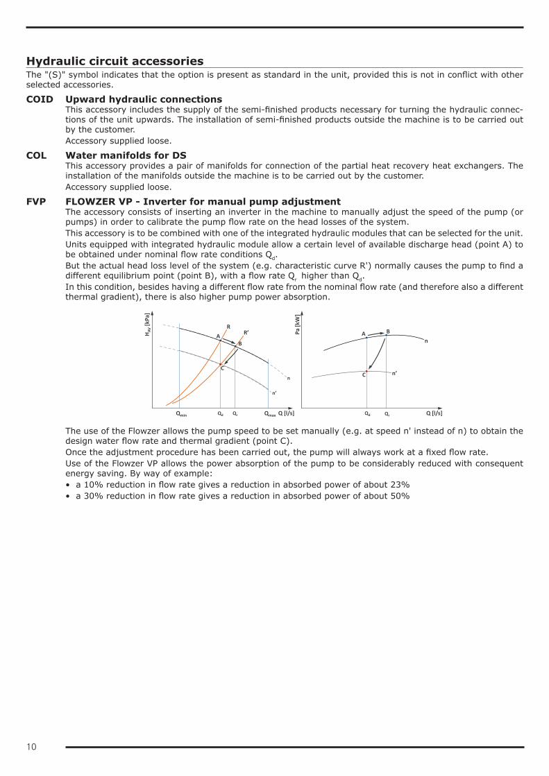
FVP FLOWZER VP - Inverter for manual pump adjustmentThe accessory consists of inserting an inverter in the machine to manually adjust the speed of the pump (or pumps) in order to calibrate the pump flow rate on the head losses of the system.This accessory is to be combined with one of the integrated hydraulic modules that can be selected for the unit.Units equipped with integrated hydraulic module allow a certain level of available discharge head (point A) to be obtained under nominal flow rate conditions Qd.But the actual head loss level of the system (e.g. characteristic curve R') normally causes the pump to find a different equilibrium point (point B), with a flow rate Qr higher than Qd.In this condition, besides having a different flow rate from the nominal flow rate (and therefore also a different thermal gradient), there is also higher pump power absorption.
QrQd Q [l/s]
n’
Qmin
n
Qmax
HAV
[kPa
]
n
n’
Pa [k
W]
Q [l/s]
RR’
Qd Qr
A B
C
AB
C
The use of the Flowzer allows the pump speed to be set manually (e.g. at speed n' instead of n) to obtain the design water flow rate and thermal gradient (point C).Once the adjustment procedure has been carried out, the pump will always work at a fixed flow rate.Use of the Flowzer VP allows the power absorption of the pump to be considerably reduced with consequent energy saving. By way of example:• a 10% reduction in flow rate gives a reduction in absorbed power of about 23%• a 30% reduction in flow rate gives a reduction in absorbed power of about 50%

11
FVD FLOWZER VD - Transducer for automatic adjustmentFlowzer VD requires a pressure transducer to be installed in the machine. Through this transducer, the inverter can gauge the actual pressure at the ends of the system and automatically adapt the pump speed to obtain a set available discharge head value. Flowzer VD must be combined with Flowzer VP.This accessory therefore allows a constant pressure system to be achieved.
Q [l/s]
R
n’’’n’’
n’
Qmin
n
Qmax
HAV
[kPa
]
Hd
R’R’’
R’’’
Q’’’ Q’’ Q’ Q
Pa [k
W]
Q’’’ Q’’ Q’ Q
n
n’
n’’n’’’
Q [l/s]
With the Flowzer VD, the customer can set, directly on the inverter, the available discharge head value Hd that the unit must maintain.As can be seen in the graph, as the system user points close, the resistance curve of the system shifts to the left and therefore the inverter will be able to reduce the pump speed in order to keep the available discharge head of the unit constant. By doing so, an immediate reduction in the power absorbed by the pump will be obtained.The customer will have to check that, in minimum flow rate conditions (that is, with the maximum number of user points closed), this is always higher than or equal to the minimum flow rate allowed by the unit.This accessory is useful when the total head losses of the circuit are slightly variable or when they change depending on the seasons (for example, some user points are active only during summer operation and not during winter operation).The use of this accessory also allows the pump speed to be adapted to possible fouling of the filter on the hydraulic circuit.
FVF FLOWZER VFPP – Kit for variable flow rate primary circuit pump with bypass valve includedThe Flowzer VFPP allows you to implement a variable flow rate primary hydraulic circuit using a single pumping unit driven by inverter and a modulating bypass valve, all managed by a dedicated controller installed in the unit.This accessory allows you to implement an alternative plant-engineering solution to the classic system with a fixed flow rate primary circuit and a secondary circuit, if necessary with inverter driven pump.The main advantages of this system are:• that the primary circuit pump guarantees the correct flow rate to the machine at any time, irrespective of
what is happening in the secondary circuit• that the secondary circuit pump can be expressly sized on the characteristics of the system and, if equipped
with inverter, can modulate its speed depending on the actually active loads.The simplicity of this solution necessarily means some compromises must be accepted:• having two pumping units: compared to a system with a single primary circuit, this will certainly be more
costly. Also consider that a single large pump is always energetically more efficient than two pumps of lower capacity
• having a hydraulic circuit breaker that separates primary circuit and secondary circuit sized for 100% of the nominal flow rate of the chiller and constantly affected by a water flow rate that is a waste of thermal energy and of pumping energy
• having the primary circuit pump that always operates at 100%, even in low or zero load conditions.The Flowzer VFPP must compulsorily be combined with the Flowzer VP and includes:• a pressure transducer installed at the ends of the user-side exchanger (Δpe)• a modulating bypass valve with servo-motor supplied separately with it (Vbp) (installation by the customer)• a pressure transducer supplied separately with it to measure the actual pressure present in the system (Δpp)
(installation by the customer)• an additional controller dedicated to just management of the Flowzer VFPP system that communicates with
the machine controller for optimization of capacity reduction of the unit depending on the load and pump speed

12
Use of the Flowzer VFPP allows you to:• simplify the system by eliminating a pumping unit• shut off the hydraulic circuit breaker with the modulating bypass valve that will open only if necessary• use a single inverter on the single pumping unit and therefore guarantee, in all operating conditions, the
lowest energy consumption due to just pumping.
ΔppΔpe
EXC
HAN
GER
Vbp
T
The Flowzer VFPP system controller uses an advanced algorithm that enables prevention of unnecessary waste of energy and hunting by the inverter and the bypass valve.It is the best compromise between the minimum pump speed and the bypass valve closed as much as possible.The operating principle of the Flowzer VFPP can be summarized as follows:• The Flowzer VFPP system controller modulates the pump speed based on the reading by the system trans-
ducer Δpp in order to keep the pressure at the set levels. This means that, as a result of the switching off of user points, there will be a slowing down of the pump.
• the pump will be able to slow down until the flow rate to the exchanger reaches the minimum allowed (flow rate gauged indirectly through the transducer Δpe). When this threshold is exceeded, the Flowzer VFPP con-troller opens the valve Vbp to recirculate the flow rate that is not required by the system, but is necessary to guarantee the minimum flow rate to the exchanger.
To work correctly, in the maximum capacity reduction condition of the system (that is, with all the two-way valves closed), the Flowzer VFPP needs the volume of water that the unit processes to be greater than or equal to the required minimum volume (Vmin) that must be concentrated in tank T, situated between the unit and the bypass valve.If, on some user points, the system uses three-way valves situated in the final part of the system branch (as in the figure), even when the user point is switched off, the valve guarantees a minimum circulation of water on the distribution lines, thereby preventing the water in the lines from stagnating for long periods of time with possible thermal drift problems. In this way, when any user point is reactivated, the temperature of the water in the line will already be the correct one, so preventing thermal inertia effects.The bypass valve Vbp supplied with the Flowzer VFPP is controlled through an 0-10V signal and therefore you are advised to install it within 30m of the unit.The pressure traducer Δpp is a differential transducer and therefore, to install it, you will only need to have two 1/4" female fittings in a suitable part of the system. This transducer is connected to the machine controller with a 4-20mA signal and therefore you are advised to install it within 200m of the unit.The position in which to install this transducer should be chosen considering that:• to ensure correct reading of the transducer, it is advisable for the capillaries not to exceed a length of one
metre• to ensure the correct pressure is available for all user points, you are advised to position the transducer
near the user point that is affected by the highest load losses of the line or in any case in a part where the average pressure of the system can be measured.
Bypass valve diameter18.4 2"1/220.4 2"1/224.4 2"1/226.4 3"30.4 3"34.4 4"
Bypass valve diameter38.4 4"40.4 4"48.4 4"54.4 4"56.6 5"60.6 5"

13
VSS Source-side safety valveWith this accessory, a safety valve is inserted in the hydraulic circuit of the unit: when the calibration pressure is reached, the valve opens and, by discharging (to be routed by the customer), prevents the system pressure from reaching limits that are dangerous for the components present in the system. The valves have positive action, that is, performance is guaranteed even if the diaphragm deteriorates or breaks.
VSWU User-side safety valveWith this accessory, a safety valve is inserted in the hydraulic circuit of the unit: when the calibration pressure is reached, the valve opens and, by discharging (to be routed by the customer), prevents the system pressure from reaching limits that are dangerous for the components present in the system. The valves have positive action, that is, performance is guaranteed even if the diaphragm deteriorates or breaks.
VSWR Heat recovery-side safety valveWith this accessory, a safety valve is inserted in the hydraulic circuit of the unit: when the calibration pressure is reached, the valve opens and, by discharging (to be routed by the customer), prevents the system pressure from reaching limits that are dangerous for the components present in the system. The valves have positive action, that is, performance is guaranteed even if the diaphragm deteriorates or breaks.

14
Electrical accessoriesThe "(S)" symbol indicates that the option is present as standard in the unit, provided this is not in conflict with other selected accessories.
CA Advanced controlWith this accessory, the advanced control is used also for sizes/versions provided with the parametric control as standard.
CBBx Provision for Blue Box remote condenserThis accessory is compulsory when the unit is coupled to the remote condenser combined as per catalogue and supplied from the factory.When this accessory is present, the protective devices and contactors of the remote condenser are arranged in the electrical control panel of the internal unit. If the condensation control with speed adjuster is required, this too will be installed in the electrical control panel of the internal unit.The remote condenser obligatorily takes its power directly from the internal unit.This accessory can be combined only with the remote condensers supplied from the factory, which comply with the combination suggested in the catalogue and are ordered at the same time as the unit. For combinations other than the factory combinations, their feasibility must be checked with our sales department.
COTW Outgoing water temperature controlWith this accessory, outgoing instead of incoming water temperature control is used.
CSP Set point compensation depending on external air temperatureFor units fitted with this accessory, the set point of the unit is set so that it can vary between two values, a maximum and a minimum, depending on the external air temperature. The compensation ramp and the max-imum and minimum values of the set point can be changed by the user.Unless otherwise specified in the order, the controller will be set to implement a positive compensation logic according to the temperatures shown in the following diagrams:
DAA Double power supply with automatic switchingA motor-driven automatic switch to which to connect two separate power supply lines (for example, one from the mains power line and one from the uninterruptible power supply unit) is installed in the electrical control panel of the unit.The switching from one line to another is automatic and obligatorily requires passing through the OFF position.
DAM Double power supply with manual switchingA manual switch to which to connect two separate power supply lines (for example, one from the mains power line and one from the uninterruptible power supply unit) is installed in the electrical control panel of the unit.The switching from one line to another is manual and obligatorily requires passing through the OFF position.When this accessory is requested, the power supply of the unit must compulsorily include neutral.
GLO Modbus Lonworks GatewayWith this accessory, a RS485/Lon gateway is installed inside the electrical control panel.By default, the programming gives read-only access to the control of the unit. Enabling of read/write access should be requested when ordering.
IA Automatic circuit breakersWith this accessory, automatic circuit breakers are installed instead of fuses for the protection of auxiliary loads. Also, the same accessory uses automatic circuit breakers with adjustable thermal overload protection to protect the compressors.
LIID Limitation of the current absorbed by digital inputWhen this accessory is requested, a digital input is prepared in the terminal board to activate the forced ca-pacity reduction of the unit to a set fixed level.This accessory is useful when there is a need to necessarily limit the power absorbed by the unit as regards particular conditions.We point out that, in some conditions (for example, during defrosting, oil return cycles or hourly compressor rotation procedures), the controller could force the unit to operate at full capacity for limited periods of time.

15
FMx Multilogic FunctionThe Multilogic function allows management of up to 32 units equipped with advanced Bluethink controller and connected in hydraulic parallel with each other.
On the basis of the information recorded by the temperature probes installed on the delivery and return man-ifolds of the system, with the master unit, a capacity request is generated that is distributed among the units connected in the Multilogic network according to settable priority and optimization logics.If communication between the units fails or if the master is off-line, the slave units can continue to work ac-cording to the set thermoregulation parameters.The connected units can be different from each other, in terms of capacity and set-up, provided the following rules are complied with:• if there are both chiller units and heat pumps in the Multilogic network, the Master unit must obligatorily be
one of the HP units• if there are both free cooling and non free-cooling units in the Multilogic network, the Master unit must ob-
ligatorily be one of the free-cooling units.The Multilogic function that can be requested with the unit can be:• FM0: Multilogic function for Slave unit• FM2: Multilogic function for Master unit for managing up to 2 Slaves• FM6: Multilogic function for Master unit for managing up to 6 SlavesIf you need to connect more than 6 slaves (up to 31), you can ask for a quotation from our sales department.For the slave units, the accessory requires:• programming of the unit as slave of a system of machines in Multilogic networkFor the master units, the accessory requires:• programming of the unit as master of a system of machines in Multilogic network• entering of the parameters necessary for connection with the individual slave units• installation in the electrical control panel of a network switch to allow the units to be connected in a LAN
network.• the supply of 2 temperature probes to be positioned on the delivery and return manifold of the system (sup-
plied separately with it, installation and wiring by the customer)The connection between the master unit and the slave units made with a CAT cable. 5E/UTP (prepared by the customer) with RJ45 connectors. Maximum cable length 100m.For further details, please refer to the controller manual.
NSS Night Shift SystemThis accessory is applied to LC and LC/HP units combined with a remote condenser with speed adjuster (or EC fans) managed directly by the control of the internal unit.In the day time band, which is normally the one with the highest heat load, priority is given to efficiency and therefore the machine works with a fan control curve that maximises the EER. So, in this time band, the unit is a high efficiency machine.In the night time band (or in any case from the time band decided by the customer), the priority changes to limiting the noisiness of the machine and therefore the control carries out an adjustment of the control ramp of the condensing fans, thereby reducing the air flow rate and consequently the noise emission level. So, in this time band, the unit is a super low noise machine.In any case, if there is a need for additional cooling capacity, the controller will manage the demand, if neces-sary, by accelerating the fans and keeping condensation within the correct operating limits.The time slots can be set from the control depending on installation requirements.When the unit is working in heat pump mode, in order to maximise the COP and to obtain the widest possible operating limits, the control of the unit forces the fans to the maximum speed also during the night time bands.

16
PBA BACnet protocol over IP (Ethernet)The controller is set for use, in read and write mode, of the BACnet port on IP protocol.By default, the programming gives read-only access to the control of the unit. Enabling of read/write access should be requested when ordering.
R1PU Relay for management of 1 external user-side pumpThis accessory can be requested for units without user-side pumps and allows a pump outside the machine to be controlled.
R2PU Relay for management of 2 external user-side pumpsThis accessory can be requested for units without user-side pumps and allows two pumps outside the machine to be controlled with a running/stand-by logic by implementing a rotation on the hours of operation.
RE1S Relay for management of 1 external source-side pumpThis accessory can be requested for units without source-side pumps and allows a pump outside the machine to be controlled.
RE2S Relay for management of 2 external source-side pumpsThis accessory can be requested for units without source-side pumps and allows two pumps outside the ma-chine to be controlled with a running/stand-by logic by implementing a rotation on the hours of operation.
R1PR Relay for management of 1 external heat recovery-side pumpThis accessory can be requested for units without heat recovery pumps (DC) and allows a pump outside the machine to be controlled.
R2PR Relay for management of 2 external heat recovery-side pumpsThis accessory can be requested for units without heat recovery pumps (DC) and allows two pumps outside the machine to be controlled with a running/stand-by logic by implementing a rotation on the hours of operation.
RIF Power factor correction to cosφ ≥ 0.9With this accessory, an electrical control panel, containing power factor correction condensers to bring the cosφ of the unit to being greater than 0.95, is supplied loose. The condensers should be connected (by the customer) to the electrical control panel of the unit in the specially prepared terminal board.Besides reducing the absorbed reactive power, the use of this accessory also allows the maximum absorbed current to be lowered.
RMMT Maximum and minimum voltage relayThis accessory constantly monitors the voltage value and the unit's power supply phase sequence. If the sup-ply voltage does not fall within the set parameters or there is a phase reversal, an alarm is generated that stops the machine to prevent damage to its main parts
SB Heat recovery-side remote-controlled operating probeThis accessory includes the supply of a probe to be positioned in the hot tank connected to the heat recovery heat exchanger. When the set point temperature is reached in the tank, the unit also stops the pumps to guar-antee the maximum energy saving.The circulation of water in the tank to the system is to be provided by the customer.The accessory is available only for units with DC set-up and with built-in user-side hydraulic module or with the "Relay for management of 1/2 external heat recovery-side pumps" accessory.
SFU User-side remote-controlled operating probeWith this accessory, the operating probe is to be placed on a tank outside the machine. When the set point temperature is reached in the tank, the unit also stops the pumps to guarantee the maximum energy saving.The circulation of water in the tank to the system is to be provided by the customer.The accessory is available only for units with built-in user-side hydraulic module or with the "Relay for man-agement of 1/2 external user-side pumps" accessory.

17
SETD Double set point from digital inputThe accessory allows you to preset two different operating set points and manage the change from one to the other through a digital signal.The set point temperatures must be specified when ordering. For optimization of the unit, reference will be made to the lower set point in chiller mode and the higher set point in heat pump mode.Unless otherwise specified in the order, the controller will be set at the factory with the following temperatures:• in chiller mode, set point 1 to 7°C and set point 2 to 12°C• in heat pump mode (only for HP units) set point 1 to 45°C and set point 2 to 40°C
SETV Variable set point with remote signalThe accessory allows the set point to be varied continuously between two preset values, a maximum and a minimum, depending on an external signal that can be of the 0-1V, 0-10V or 4-20mA type.The set point temperatures and the type of signal to use for the adjustment must be specified when ordering. For optimization of the unit, reference will be made to the lower set point in chiller mode and the higher set point in heat pump mode.Unless otherwise specified in the order, the controller will be set at the factory with 0-10V analogue input and with the following temperatures:• in chiller mode, 0V will correspond to a set point of 7°C and 10V will correspond to a set point of 12°C• in heat pump mode (only for HP units), 0V will correspond to a set point of 45°C and 10V will correspond
to a set point of 40°C
SOFT Electronic soft-starterThe scroll compressors have DOL (Direct On Line) starting and therefore the maximum inrush current IMIC will be 4/5 times its nominal current Inom.If the unit is equipped with the electronic soft-starter accessory, the starting of each compressor is done with an acceleration ramp that allows the effective value (rms value) of the inrush current of the individual com-pressor to be lowered.
rpm
I [A]
Inom
IMIC
Current trend without accessory Electronic soft-starter
rpm
I [A]
IMIC
Inom
Current trend with accessory Electronic soft-starter
TERM Remote-controlled user terminal panelThis accessory allows the terminal normally situated on the machine to be replicated on a support situated at a distance. It is particularly suitable when the unit is placed in an area that is not easily accessible.The accessory is supplied loose and is to be installed by the customer at a maximum distance of 120m from the unit. We advise using a cable of the following type: "TECO O.R. FE 2x2xAWG24 SN/ST/PUR".

18
Other accessoriesThe "(S)" symbol indicates that the option is present as standard in the unit, provided this is not in conflict with other selected accessories.
AG Rubber anti-vibration mountsThese allow you to reduce the vibrations transmitted from the unit to the surface it is standing on.Accessory supplied loose.
AM Spring anti-vibration mountsThese allow you to reduce the vibrations transmitted from the unit to the surface it is standing on.Accessory supplied loose.
GABB Packaging in wooden crateThe unit is protected by a made-to-measure wooden crate. The accessory is mandatory if shipping by contain-er is required
KFW Water filter kitTo protect the elements of the hydraulic circuit (in particular, the exchangers), there are Y filters that can stop and settle the particles that are normally present in the water flow and would otherwise settle in the more delicate parts of the hydraulic circuit and damage its heat exchange capacity.The kit involves the supply of a filter for each exchanger present in the machine.Installation of the water filter is mandatory even when it is not supplied as an accessory.Accessory supplied loose.
PREA Unit suitable to be disassembled on siteThe unit is delivered so that it can be disassembled easily on site if this makes the installation operations easier.A unit requested with this option is supplied:• screwed instead of riveted• with plugged and not welded pipes• without refrigerant charge• untested• covered by the warranty only if reassembled and screwed together by personnel authorized by the factory

19

20
TECHNICAL SPECIFICATIONSTETRIS W REV 3.2 4.2 5.2 6.2 7.2 8.2 9.2 10.2Cooling (W30; W7)Refrigeration capacity (1) kW 38,2 43,4 49,8 55,2 64,0 71,9 82,0 99,6Total absorbed power (1) kW 8,0 9,1 10,4 11,4 13,1 14,7 16,6 20,2EER (1) 4,77 4,75 4,78 4,86 4,88 4,90 4,93 4,94ESEER 5,57 5,55 5,63 5,70 5,65 5,65 5,66 5,72CompressorsCompressors/Circuits n°/n° 2/1 2/1 2/1 2/1 2/1 2/1 2/1 2/1Minimum capacity reduction step % 50% 50% 50% 50% 50% 50% 50% 50%Refrigerant charge kg 2 3 3 4 4 6 6 7User-side heat exchangerQuantity n° 1 1 1 1 1 1 1 1Water flow rate (W30; W7) (1) m³/h 6,6 7,5 8,6 9,5 11,1 12,4 14,2 17,2Head loss (W30; W7) (1) kPa 22 23 22 21 26 32 32 35Source-side heat exchangerQuantity n° 1 1 1 1 1 1 1 1Water flow rate (W30; W7) (1) m³/h 7,9 9,0 10,3 11,4 13,2 14,8 16,9 20,5Head loss (W30; W7) (1) kPa 34 39 39 42 46 33 35 36User-side hydraulic modulesVolume of the expansion vessel l 5 5 5 18 18 18 18 18Volume of the buffer tank l 200 200 200 200 200 200 200 200Standard pumpsPump model standard P1 P2 P4 P4 P4 P4 P7 P7Available head (1P) (1) kPa 117 154 159 156 144 127 129 101Available head (2P) (1) kPa 120 158 163 162 151 137 141 119Oversize pumpsPump model oversized P3 P3 P5 P5 P5 P6 P8 P9Available head (1PM) (1) kPa 201 201 201 201 201 201 201 201Available head (2PM) (1) kPa 204 204 204 204 204 204 204 204Pumps for glycolPump model for high glycol P5 P5 P5 P5 P8 P8 P8 P10Available head (1PG) (1) kPa 205 199 191 189 181 167 155 141Available head (2PG) (1) kPa 201 194 184 181 170 153 137 114Source-side/heat recovery-side hydraulic modulesVolume of the expansion vessel l 5 5 5 18 18 18 18 18Standard pumpsPump model standard P4 P4 P4 P4 P4 P7 P7 P7Available head (1S o 1R) (1) kPa 151 142 133 128 109 145 132 105Available head (2S o 2R) (1) kPa 155 147 139 136 119 149 137 113Oversize pumpsPump model oversized P5 P5 P5 P5 P5 P8 P8 P10Available head (1SM o 1RM) (1) kPa 196 188 178 174 154 183 170 162Available head (2SM o 2RM) (1) kPa 200 193 185 182 165 187 176 170Pumps for glycolPump model for high glycol P5 P5 P5 P8 P8 P8 P8 P12Available head (1SG o 2RG) (1) kPa 168 156 143 146 127 153 136 259Available head (2SG o 2RG) (1) kPa 161 147 132 133 108 146 127 245Noise levelsSound power level basic unit (4) dB(A) 73 75 75 77 77 78 79 80Sound pressure level basic unit (5) dB(A) 57 59 60 62 62 63 63 65Sound power level LN version (4) dB(A) 66 68 68 70 70 71 72 73Sound pressure level LN version (5) dB(A) 50 52 53 55 55 56 56 58Dimensions and weights of basic unitLength mm 1.633 1.633 1.633 1.633 1.633 1.633 1.633 1.633Depth mm 792 792 792 792 792 792 792 792Height mm 967 967 967 967 967 967 967 967Operating weight (6) kg 330 340 380 400 400 440 460 470 (1) Source side heat exchanger inlet/outlet water temperature 30/35°C; user side heat exchanger inlet/outlet water temperature 12/7°C. Values
compliant with standard EN 14511(4) Sound power level obtained from measurements carried out in accordance with standard ISO 3744. Reference conditions: source side heat ex-
changer inlet/outlet water temperature 30/35°C; user side heat exchanger inlet/outlet water temperature 12/7°C(5) Sound pressure level measured at a distance of 1 metre from the unit in free field, with directivity factor Q=2. Reference conditions: source side
heat exchanger inlet/outlet water temperature 30/35°C; user side heat exchanger inlet/outlet water temperature 12/7°C(6) The weight refers to the unit without any accessory. The introduction of some accessories such as hydraulic modules or recovery exchangers can
lead to increased weight that can exceed 10%. For further details refer to the specific drawing of the selected configuration.

21
TETRIS W REV 12.2 13.2 15.2 17.2 19.2 20.2 24.2 27.2Cooling (W30; W7)Refrigeration capacity (1) kW 113,0 130,5 144,3 160,5 181,9 199,5 221,3 250,7Total absorbed power (1) kW 23,0 26,5 29,3 32,6 37,3 41,6 45,8 51,5EER (1) 4,91 4,93 4,93 4,92 4,88 4,80 4,83 4,87ESEER 5,69 5,65 5,71 5,67 5,68 5,63 5,73 5,68CompressorsCompressors/Circuits n°/n° 2/1 2/1 2/1 2/1 2/1 2/1 2/1 2/1Minimum capacity reduction step % 43% 50% 44% 50% 45% 50% 50% 50%Refrigerant charge kg 9 10 11 13 14 15 22 22User-side heat exchangerQuantity n° 1 1 1 1 1 1 1 1Water flow rate (W30; W7) (1) m³/h 19,5 22,5 24,9 27,7 31,4 34,5 38,2 43,3Head loss (W30; W7) (1) kPa 35 33 33 33 39 44 49 52Source-side heat exchangerQuantity n° 1 1 1 1 1 1 1 1Water flow rate (W30; W7) (1) m³/h 23,3 26,9 29,7 33,1 37,5 41,3 45,8 51,8Head loss (W30; W7) (1) kPa 38 40 43 46 49 51 35 36User-side hydraulic modulesVolume of the expansion vessel l 18 18 18 18 18 18 18 18Volume of the buffer tank l 200 200 200 200 200 200 270 270Standard pumpsPump model standard P8 P8 P10 P10 P10 P11 P14 P14Available head (1P) (1) kPa 152 133 143 128 100 153 147 131Available head (2P) (1) kPa 159 143 155 142 119 163 159 147Oversize pumpsPump model oversized P9 P10 P11 P11 P11 P12 P15 P15Available head (1PM) (1) kPa 201 201 201 201 201 201 201 201Available head (2PM) (1) kPa 204 204 204 204 204 204 204 204Pumps for glycolPump model for high glycol P11 P12 P13 P14 P15 P15 P15 P15Available head (1PG) (1) kPa 216 270 327 157 212 211 189 168Available head (2PG) (1) kPa 206 256 310 136 184 196 170 144Source-side/heat recovery-side hydraulic modulesVolume of the expansion vessel l 18 18 18 18 18 18 18 18Standard pumpsPump model standard P8 P10 P10 P10 P10 P14 P14 P14Available head (1S o 1R) (1) kPa 127 143 129 110 74 136 142 114Available head (2S o 2R) (1) kPa 137 150 136 119 87 151 160 138Oversize pumpsPump model oversized P10 P11 P11 P11 P15 P15 P15 P15Available head (1SM o 1RM) (1) kPa 150 205 188 165 219 202 205 173Available head (2SM o 2RM) (1) kPa 160 212 196 175 231 217 223 196Pumps for glycolPump model for high glycol P13 P14 P14 P14 P15 P15 P15 P19Available head (1SG o 2RG) (1) kPa 318 154 145 135 175 152 158 180Available head (2SG o 2RG) (1) kPa 301 144 133 119 154 127 127 141Noise levelsSound power level basic unit (4) dB(A) 83 84 85 85 86 87 87 88Sound pressure level basic unit (5) dB(A) 66 67 69 69 70 71 71 71Sound power level LN version (4) dB(A) 76 77 78 78 79 80 80 81Sound pressure level LN version (5) dB(A) 59 60 62 62 63 64 64 64Dimensions and weights of basic unitLength mm 1.633 1.633 1.633 1.633 1.633 1.633 1.633 1.633Depth mm 792 792 792 792 792 792 792 792Height mm 1.880 1.880 1.880 1.880 1.880 1.880 1.880 1.880Operating weight (6) kg 580 670 700 740 770 800 860 880 (1) Source side heat exchanger inlet/outlet water temperature 30/35°C; user side heat exchanger inlet/outlet water temperature 12/7°C. Values
compliant with standard EN 14511(4) Sound power level obtained from measurements carried out in accordance with standard ISO 3744. Reference conditions: source side heat ex-
changer inlet/outlet water temperature 30/35°C; user side heat exchanger inlet/outlet water temperature 12/7°C(5) Sound pressure level measured at a distance of 1 metre from the unit in free field, with directivity factor Q=2. Reference conditions: source side
heat exchanger inlet/outlet water temperature 30/35°C; user side heat exchanger inlet/outlet water temperature 12/7°C(6) The weight refers to the unit without any accessory. The introduction of some accessories such as hydraulic modules or recovery exchangers can
lead to increased weight that can exceed 10%. For further details refer to the specific drawing of the selected configuration.

22
TETRIS W REV 30.3 34.3 40.3 18.4 20.4 24.4 26.4 30.4Cooling (W30; W7)Refrigeration capacity (1) kW 309,2 345,0 383,5 162,6 196,8 224,7 253,1 286,8Total absorbed power (1) kW 64,2 71,1 79,4 33,3 40,4 45,9 51,9 58,6EER (1) 4,82 4,85 4,83 4,88 4,87 4,90 4,88 4,89ESEER 5,75 5,75 5,71 5,81 5,87 5,86 5,88 5,88CompressorsCompressors/Circuits n°/n° 3/1 3/1 3/1 4/2 4/2 4/2 4/2 4/2Minimum capacity reduction step % 33% 33% 33% 25% 25% 21% 25% 22%Refrigerant charge kg 26 30 34 13 15 17 20 22User-side heat exchangerQuantity n° 1 1 1 1 1 1 1 1Water flow rate (W30; W7) (1) m³/h 53,4 59,6 66,3 28,1 34,0 38,8 43,7 49,5Head loss (W30; W7) (1) kPa 53 53 54 28 30 30 29 32Source-side heat exchangerQuantity n° 1 1 1 1 1 1 1 1Water flow rate (W30; W7) (1) m³/h 64,0 71,3 79,3 33,6 40,7 46,4 52,3 59,2Head loss (W30; W7) (1) kPa 49 41 44 32 33 38 41 44User-side hydraulic modulesVolume of the expansion vessel l 18 18 18 18 18 18 18 18Volume of the buffer tank l 400 400 400 270 270 270 270 400Standard pumpsPump model standard P14 P14 P15 P10 P10 P14 P14 P14Available head (1P) (1) kPa 126 102 126 134 114 163 150 158Available head (2P) (1) kPa 136 115 142 149 124 176 167 167Oversize pumpsPump model oversized P15 P15 P16 P11 P11 P15 P15 P15Available head (1PM) (1) kPa 201 201 201 201 201 201 201 201Available head (2PM) (1) kPa 204 204 204 204 204 204 204 204Pumps for glycolPump model for high glycol P19 P19 P19 P14 P15 P15 P15 P15Available head (1PG) (1) kPa 199 185 178 169 228 212 195 188Available head (2PG) (1) kPa 184 166 155 147 213 193 170 175Source-side/heat recovery-side hydraulic modulesVolume of the expansion vessel l 18 18 18 18 18 18 18 18Standard pumpsPump model standard P14 P14 P17 P10 P14 P14 P14 P14Available head (1S o 1R) (1) kPa 99 75 88 118 155 135 113 121Available head (2S o 2R) (1) kPa 114 93 110 127 169 154 137 133Oversize pumpsPump model oversized P18 P18 P19 P11 P15 P15 P15 P15Available head (1SM o 1RM) (1) kPa 167 160 191 173 221 198 171 173Available head (2SM o 2RM) (1) kPa 182 178 213 183 236 217 195 185Pumps for glycolPump model for high glycol P19 P20 P20 P14 P15 P15 P19 P19Available head (1SG o 2RG) (1) kPa 176 202 181 152 176 151 180 193Available head (2SG o 2RG) (1) kPa 151 171 143 135 151 119 140 172Noise levelsSound power level basic unit (4) dB(A) 88 88 90 82 83 86 87 88Sound pressure level basic unit (5) dB(A) 71 71 73 65 66 69 69 71Sound power level LN version (4) dB(A) 81 81 83 75 76 79 80 81Sound pressure level LN version (5) dB(A) 64 64 66 58 59 62 62 64Dimensions and weights of basic unitLength mm 2.017 2.017 2.017 2.017 2.017 2.834 2.834 2.834Depth mm 872 872 872 872 872 872 872 872Height mm 1.880 1.880 1.880 1.880 1.880 1.880 1.880 1.880Operating weight (6) kg 1.220 1.260 1.340 770 800 1.030 1.210 1.270 (1) Source side heat exchanger inlet/outlet water temperature 30/35°C; user side heat exchanger inlet/outlet water temperature 12/7°C. Values
compliant with standard EN 14511(4) Sound power level obtained from measurements carried out in accordance with standard ISO 3744. Reference conditions: source side heat ex-
changer inlet/outlet water temperature 30/35°C; user side heat exchanger inlet/outlet water temperature 12/7°C(5) Sound pressure level measured at a distance of 1 metre from the unit in free field, with directivity factor Q=2. Reference conditions: source side
heat exchanger inlet/outlet water temperature 30/35°C; user side heat exchanger inlet/outlet water temperature 12/7°C(6) The weight refers to the unit without any accessory. The introduction of some accessories such as hydraulic modules or recovery exchangers can
lead to increased weight that can exceed 10%. For further details refer to the specific drawing of the selected configuration.

23
TETRIS W REV 34.4 38.4 40.4 48.4 54.4 56.6 60.6Cooling (W30; W7)Refrigeration capacity (1) kW 319,0 363,3 408,4 453,8 512,9 544,8 615,0Total absorbed power (1) kW 65,6 75,2 84,4 93,0 103,8 111,9 125,8EER (1) 4,86 4,83 4,84 4,88 4,94 4,87 4,89ESEER 5,86 5,85 5,83 5,93 6,00 5,87 5,92CompressorsCompressors/Circuits n°/n° 4/2 4/2 4/2 4/2 4/2 6/2 6/2Minimum capacity reduction step % 25% 23% 25% 25% 25% 15% 17%Refrigerant charge kg 26 45 49 37 42 44 48User-side heat exchangerQuantity n° 1 1 1 1 1 1 1Water flow rate (W30; W7) (1) m³/h 55,0 62,7 70,5 78,2 88,4 93,9 106,1Head loss (W30; W7) (1) kPa 31 44 46 28 30 31 34Source-side heat exchangerQuantity n° 1 1 1 1 1 1 1Water flow rate (W30; W7) (1) m³/h 65,9 75,1 84,4 93,7 105,7 112,5 126,9Head loss (W30; W7) (1) kPa 49 53 55 46 48 52 54User-side hydraulic modulesVolume of the expansion vessel l 18 18 18 25 25 25 25Volume of the buffer tank l 400 400 400 400 400 400 400Standard pumpsPump model standard P14 P14 P18 P18 P18 P18 P18Available head (1P) (1) kPa 144 106 156 160 135 164 137Available head (2P) (1) kPa 155 121 174 182 163 171 147Oversize pumpsPump model oversized P15 P16 P19 P19 P19 P19 P20Available head (1PM) (1) kPa 201 201 201 201 201 201 201Available head (2PM) (1) kPa 204 204 204 204 204 204 204Pumps for glycolPump model for high glycol P19 P19 P19 P20 P23 P23 P23Available head (1PG) (1) kPa 229 201 183 228 226 241 217Available head (2PG) (1) kPa 213 180 157 195 185 229 202Source-side/heat recovery-side hydraulic modulesVolume of the expansion vessel l 18 18 18 25 25 25 25Standard pumpsPump model standard P15 P17 P18 P18 P22 P22 P22Available head (1S o 1R) (1) kPa 141 89 116 157 184 171 141Available head (2S o 2R) (1) kPa 157 109 141 165 194 182 156Oversize pumpsPump model oversized P16 P19 P19 P20 P23 P23 P23Available head (1SM o 1RM) (1) kPa 230 191 163 238 242 229 202Available head (2SM o 2RM) (1) kPa 245 211 188 246 252 241 216Pumps for glycolPump model for high glycol P19 P20 P21 P22 P23 P23 P23Available head (1SG o 2RG) (1) kPa 177 177 211 153 190 171 133Available head (2SG o 2RG) (1) kPa 150 142 168 139 173 151 108Noise levelsSound power level basic unit (4) dB(A) 88 89 90 90 91 91 91Sound pressure level basic unit (5) dB(A) 71 72 72 73 73 73 73Sound power level LN version (4) dB(A) 81 82 83 83 84 84 84Sound pressure level LN version (5) dB(A) 64 65 65 66 66 66 66Dimensions and weights of basic unitLength mm 2.834 2.834 2.834 2.834 2.834 3.334 3.334Depth mm 872 872 872 872 872 872 872Height mm 1.880 1.880 1.880 1.880 1.880 1.880 1.880Operating weight (6) kg 1.350 1.500 1.580 1.630 1.710 2.030 2.150 (1) Source side heat exchanger inlet/outlet water temperature 30/35°C; user side heat exchanger inlet/outlet water temperature 12/7°C. Values
compliant with standard EN 14511(4) Sound power level obtained from measurements carried out in accordance with standard ISO 3744. Reference conditions: source side heat ex-
changer inlet/outlet water temperature 30/35°C; user side heat exchanger inlet/outlet water temperature 12/7°C(5) Sound pressure level measured at a distance of 1 metre from the unit in free field, with directivity factor Q=2. Reference conditions: source side
heat exchanger inlet/outlet water temperature 30/35°C; user side heat exchanger inlet/outlet water temperature 12/7°C(6) The weight refers to the unit without any accessory. The introduction of some accessories such as hydraulic modules or recovery exchangers can
lead to increased weight that can exceed 10%. For further details refer to the specific drawing of the selected configuration.

24
TETRIS W REV /HP 3.2 4.2 5.2 6.2 7.2 8.2 9.2 10.2Cooling (W30; W7)Refrigeration capacity (1) kW 34,8 40,0 43,2 50,6 59,3 68,0 76,2 88,7Total absorbed power (1) kW 8,2 9,4 10,2 11,6 13,4 15,2 17,1 20,8EER (1) 4,22 4,24 4,22 4,38 4,42 4,48 4,45 4,27ESEER 4,92 5,00 5,00 5,12 5,11 5,14 5,08 4,91Heating (W10; W45)Heating capacity (2) kW 43,3 49,8 53,2 60,6 71,8 81,7 90,6 107,9Total absorbed power (2) kW 10,1 11,6 12,3 14,1 16,5 18,9 20,9 25,0COP (2) 4,27 4,28 4,31 4,29 4,34 4,33 4,34 4,31CompressorsCompressors/Circuits n°/n° 2/1 2/1 2/1 2/1 2/1 2/1 2/1 2/1Minimum capacity reduction step % 50% 50% 50% 50% 50% 50% 50% 50%Refrigerant charge kg 2 3 3 4 4 6 6 7User-side heat exchangerQuantity n° 1 1 1 1 1 1 1 1Water flow rate (W30; W7) (1) m³/h 6,0 6,9 7,5 8,7 10,2 11,8 13,2 15,3Head loss (W30; W7) (1) kPa 19 20 19 19 23 66 28 31Water flow rate (W10; W45) (2) m³/h 7,4 8,5 9,1 10,4 12,3 14,0 15,5 18,5Head loss (W10; W45) (2) kPa 28 30 28 26 32 40 39 45Source-side heat exchangerQuantity n° 1 1 1 1 1 1 1 1Water flow rate (W30; W7) (1) m³/h 7,3 8,4 9,1 10,6 12,4 14,2 16,0 18,7Head loss (W30; W7) (1) kPa 48 50 48 45 53 44 34 38User-side hydraulic modulesVolume of the expansion vessel l 5 5 5 18 18 18 18 18Volume of the buffer tank l 200 200 200 200 200 200 200 200Standard pumpsPump model standard P1 P2 P4 P4 P4 P4 P7 P7Available head (1P) (1) kPa 117 154 159 156 144 127 129 101Available head (2P) (1) kPa 120 158 163 162 151 137 141 119Oversize pumpsPump model oversized P3 P3 P5 P5 P5 P6 P8 P9Available head (1PM) (1) kPa 201 201 201 201 201 201 201 201Available head (2PM) (1) kPa 204 204 204 204 204 204 204 204Pumps for glycolPump model for high glycol P5 P5 P5 P5 P8 P8 P8 P10Available head (1PG) (1) kPa 205 199 191 189 181 167 155 141Available head (2PG) (1) kPa 201 194 184 181 170 153 137 114Source-side hydraulic modulesVolume of the expansion vessel l 5 5 5 18 18 18 18 18Standard pumpsPump model standard P4 P4 P4 P4 P4 P7 P7 P7Available head (1S) (1) kPa 151 142 133 128 109 145 132 105Available head (2S) (1) kPa 155 147 139 136 119 149 137 113Oversize pumpsPump model oversized P5 P5 P5 P5 P5 P8 P8 P10Available head (1SM) (1) kPa 196 188 178 174 154 183 170 162Available head (2SM) (1) kPa 200 193 185 182 165 187 176 170Pumps for glycolPump model for high glycol P5 P5 P5 P8 P8 P8 P8 P12Available head (1SG) (1) kPa 168 156 143 146 127 153 136 259Available head (2SG) (1) kPa 161 147 132 133 108 146 127 245Noise levelsSound power level basic unit (4) dB(A) 73 75 75 77 77 78 79 80Sound pressure level basic unit (5) dB(A) 57 59 60 62 62 63 63 65Sound power level LN version (4) dB(A) 66 68 68 70 70 71 72 73Sound pressure level LN version (5) dB(A) 50 52 53 55 55 56 56 58Dimensions and weights of basic unitLength mm 1.633 1.633 1.633 1.633 1.633 1.633 1.633 1.633Depth mm 792 792 792 792 792 792 792 792Height mm 967 967 967 967 967 967 967 967Operating weight (6) kg 330 340 380 400 410 440 450 460 (1) Source side heat exchanger inlet/outlet water temperature 30/35°C; user side heat exchanger inlet/outlet water temperature 12/7°C. Values
compliant with standard EN 14511(2) Source-side heat exchanger inlet-outlet water temperature 10/7°C; user-side heat exchanger inlet-outlet water temperature 40/45°C. Values
compliant with standard EN 14511(4) Sound power level obtained from measurements carried out in accordance with standard ISO 3744. Reference conditions: source side heat ex-
changer inlet/outlet water temperature 30/35°C; user side heat exchanger inlet/outlet water temperature 12/7°C(5) Sound pressure level measured at a distance of 1 metre from the unit in free field, with directivity factor Q=2. Reference conditions: source side
heat exchanger inlet/outlet water temperature 30/35°C; user side heat exchanger inlet/outlet water temperature 12/7°C(6) The weight refers to the unit without any accessory. The introduction of some accessories such as hydraulic modules or recovery exchangers can
lead to increased weight that can exceed 10%. For further details refer to the specific drawing of the selected configuration.

25
TETRIS W REV /HP 12.2 13.2 15.2 17.2 19.2 20.2 24.2 27.2Cooling (W30; W7)Refrigeration capacity (1) kW 101,3 114,3 128,8 143,5 164,4 185,1 205,4 236,9Total absorbed power (1) kW 23,6 26,4 29,8 33,1 38,0 42,6 47,8 51,7EER (1) 4,29 4,33 4,32 4,33 4,33 4,34 4,30 4,58ESEER 4,94 4,93 5,00 4,94 5,00 5,06 5,07 5,19Heating (W10; W45)Heating capacity (2) kW 122,3 137,7 155,7 173,4 198,9 223,1 251,6 282,2Total absorbed power (2) kW 28,3 31,7 35,9 40,0 45,7 51,6 57,4 63,4COP (2) 4,32 4,34 4,34 4,33 4,35 4,32 4,38 4,45CompressorsCompressors/Circuits n°/n° 2/1 2/1 2/1 2/1 2/1 2/1 2/1 2/1Minimum capacity reduction step % 43% 50% 44% 50% 45% 50% 50% 50%Refrigerant charge kg 9 10 11 13 14 15 22 22User-side heat exchangerQuantity n° 1 1 1 1 1 1 1 1Water flow rate (W30; W7) (1) m³/h 17,5 19,7 22,2 24,8 28,4 32,0 35,4 40,8Head loss (W30; W7) (1) kPa 30 29 29 29 34 38 33 11Water flow rate (W10; W45) (2) m³/h 20,9 23,6 26,7 29,7 34,1 38,2 43,1 48,5Head loss (W10; W45) (2) kPa 43 41 41 42 49 54 49 16Source-side heat exchangerQuantity n° 1 1 1 1 1 1 1 1Water flow rate (W30; W7) (1) m³/h 21,4 24,1 27,2 30,3 34,7 39,0 43,4 49,6Head loss (W30; W7) (1) kPa 37 35 34 35 40 45 44 14User-side hydraulic modulesVolume of the expansion vessel l 18 18 18 18 18 18 18 18Volume of the buffer tank l 200 200 200 200 200 200 270 270Standard pumpsPump model standard P8 P8 P10 P10 P10 P11 P14 P14Available head (1P) (1) kPa 152 133 143 128 100 153 147 131Available head (2P) (1) kPa 159 143 155 142 119 163 159 147Oversize pumpsPump model oversized P9 P10 P11 P11 P11 P12 P15 P15Available head (1PM) (1) kPa 201 201 201 201 201 201 201 201Available head (2PM) (1) kPa 204 204 204 204 204 204 204 204Pumps for glycolPump model for high glycol P11 P12 P13 P14 P15 P15 P15 P15Available head (1PG) (1) kPa 216 270 327 157 212 211 189 168Available head (2PG) (1) kPa 206 256 310 136 184 196 170 144Source-side hydraulic modulesVolume of the expansion vessel l 18 18 18 18 18 18 18 18Standard pumpsPump model standard P8 P10 P10 P10 P10 P14 P14 P14Available head (1S) (1) kPa 127 143 129 110 74 136 142 114Available head (2S) (1) kPa 137 150 136 119 87 151 160 138Oversize pumpsPump model oversized P10 P11 P11 P11 P15 P15 P15 P15Available head (1SM) (1) kPa 150 205 188 165 219 202 205 173Available head (2SM) (1) kPa 160 212 196 175 231 217 223 196Pumps for glycolPump model for high glycol P13 P14 P14 P14 P15 P15 P15 P19Available head (1SG) (1) kPa 318 154 145 135 175 152 158 180Available head (2SG) (1) kPa 301 144 133 119 154 127 127 141Noise levelsSound power level basic unit (4) dB(A) 83 84 85 85 86 87 87 88Sound pressure level basic unit (5) dB(A) 66 67 69 69 70 71 71 71Sound power level LN version (4) dB(A) 76 77 78 78 79 80 80 81Sound pressure level LN version (5) dB(A) 59 60 62 62 63 64 64 64Dimensions and weights of basic unitLength mm 1.633 1.633 1.633 1.633 1.633 1.633 2.017 2.017Depth mm 792 792 792 792 792 792 872 872Height mm 1.880 1.880 1.880 1.880 1.880 1.880 1.880 1.880Operating weight (6) kg 570 660 700 730 760 800 910 960 (1) Source side heat exchanger inlet/outlet water temperature 30/35°C; user side heat exchanger inlet/outlet water temperature 12/7°C. Values
compliant with standard EN 14511(2) Source-side heat exchanger inlet-outlet water temperature 10/7°C; user-side heat exchanger inlet-outlet water temperature 40/45°C. Values
compliant with standard EN 14511(4) Sound power level obtained from measurements carried out in accordance with standard ISO 3744. Reference conditions: source side heat ex-
changer inlet/outlet water temperature 30/35°C; user side heat exchanger inlet/outlet water temperature 12/7°C(5) Sound pressure level measured at a distance of 1 metre from the unit in free field, with directivity factor Q=2. Reference conditions: source side
heat exchanger inlet/outlet water temperature 30/35°C; user side heat exchanger inlet/outlet water temperature 12/7°C(6) The weight refers to the unit without any accessory. The introduction of some accessories such as hydraulic modules or recovery exchangers can
lead to increased weight that can exceed 10%. For further details refer to the specific drawing of the selected configuration.

26
TETRIS W REV /HP 30.3 34.3 40.3 18.4 20.4 24.4 26.4 30.4Cooling (W30; W7)Refrigeration capacity (1) kW 283,4 311,1 349,3 150,9 179,2 204,1 229,8 268,6Total absorbed power (1) kW 61,9 69,1 77,1 33,4 40,4 45,7 51,3 57,2EER (1) 4,58 4,50 4,53 4,52 4,43 4,47 4,48 4,70ESEER 5,29 5,20 5,21 5,32 5,27 5,28 5,33 5,58Heating (W10; W45)Heating capacity (2) kW 334,7 377,2 415,4 182,7 216,2 246,5 273,4 308,6Total absorbed power (2) kW 74,5 85,9 94,6 40,8 48,8 55,8 62,1 69,4COP (2) 4,49 4,39 4,39 4,48 4,43 4,42 4,40 4,45CompressorsCompressors/Circuits n°/n° 3/1 3/1 3/1 4/2 4/2 4/2 4/2 4/2Minimum capacity reduction step % 33% 33% 33% 25% 25% 21% 25% 22%Refrigerant charge kg 26 30 34 13 15 17 20 22User-side heat exchangerQuantity n° 1 1 1 1 1 1 1 1Water flow rate (W30; W7) (1) m³/h 48,8 53,6 60,2 26,1 30,9 35,2 39,7 46,3Head loss (W30; W7) (1) kPa 13 15 17 33 30 33 34 30Water flow rate (W10; W45) (2) m³/h 57,4 64,7 71,3 31,3 37,0 42,2 46,8 52,9Head loss (W10; W45) (2) kPa 18 21 23 48 44 48 47 39Source-side heat exchangerQuantity n° 1 1 1 1 1 1 1 1Water flow rate (W30; W7) (1) m³/h 59,3 65,3 73,2 31,6 37,7 42,9 48,3 55,9Head loss (W30; W7) (1) kPa 16 18 20 9 10 12 13 15User-side hydraulic modulesVolume of the expansion vessel l 18 18 18 18 18 18 18 18Volume of the buffer tank l 400 400 400 270 270 270 270 400Standard pumpsPump model standard P14 P14 P15 P10 P10 P14 P14 P14Available head (1P) (1) kPa 126 102 126 134 114 163 150 158Available head (2P) (1) kPa 136 115 142 149 124 176 167 167Oversize pumpsPump model oversized P15 P15 P16 P11 P11 P15 P15 P15Available head (1PM) (1) kPa 201 201 201 201 201 201 201 201Available head (2PM) (1) kPa 204 204 204 204 204 204 204 204Pumps for glycolPump model for high glycol P19 P19 P19 P14 P15 P15 P15 P15Available head (1PG) (1) kPa 199 185 178 169 228 212 195 188Available head (2PG) (1) kPa 184 166 155 147 213 193 170 175Source-side hydraulic modulesVolume of the expansion vessel l 18 18 18 18 18 18 18 18Standard pumpsPump model standard P14 P14 P17 P10 P14 P14 P14 P14Available head (1S) (1) kPa 99 75 88 118 155 135 113 121Available head (2S) (1) kPa 114 93 110 127 169 154 137 133Oversize pumpsPump model oversized P18 P18 P19 P11 P15 P15 P15 P15Available head (1SM) (1) kPa 167 160 191 173 221 198 171 173Available head (2SM) (1) kPa 182 178 213 183 236 217 195 185Pumps for glycolPump model for high glycol P19 P20 P20 P14 P15 P15 P19 P19Available head (1SG) (1) kPa 176 202 181 152 176 151 180 193Available head (2SG) (1) kPa 151 171 143 135 151 119 140 172Noise levelsSound power level basic unit (4) dB(A) 88 88 90 82 83 86 87 88Sound pressure level basic unit (5) dB(A) 71 71 73 65 66 69 69 71Sound power level LN version (4) dB(A) 81 81 83 75 76 79 80 81Sound pressure level LN version (5) dB(A) 64 64 66 58 59 62 62 64Dimensions and weights of basic unitLength mm 2.017 2.017 2.017 2.017 2.017 2.834 2.834 2.834Depth mm 872 872 872 872 872 872 872 872Height mm 1.880 1.880 1.880 1.880 1.880 1.880 1.880 1.880Operating weight (6) kg 1.260 1.290 1.380 820 860 1.100 1.280 1.350 (1) Source side heat exchanger inlet/outlet water temperature 30/35°C; user side heat exchanger inlet/outlet water temperature 12/7°C. Values
compliant with standard EN 14511(2) Source-side heat exchanger inlet-outlet water temperature 10/7°C; user-side heat exchanger inlet-outlet water temperature 40/45°C. Values
compliant with standard EN 14511(4) Sound power level obtained from measurements carried out in accordance with standard ISO 3744. Reference conditions: source side heat ex-
changer inlet/outlet water temperature 30/35°C; user side heat exchanger inlet/outlet water temperature 12/7°C(5) Sound pressure level measured at a distance of 1 metre from the unit in free field, with directivity factor Q=2. Reference conditions: source side
heat exchanger inlet/outlet water temperature 30/35°C; user side heat exchanger inlet/outlet water temperature 12/7°C(6) The weight refers to the unit without any accessory. The introduction of some accessories such as hydraulic modules or recovery exchangers can
lead to increased weight that can exceed 10%. For further details refer to the specific drawing of the selected configuration.

27
TETRIS W REV /HP 34.4 38.4 40.4 48.4 54.4 56.6 60.6Cooling (W30; W7)Refrigeration capacity (1) kW 279,9 328,2 364,8 409,9 465,5 492,1 547,9Total absorbed power (1) kW 66,0 73,6 84,1 95,1 105,8 111,3 125,4EER (1) 4,24 4,46 4,34 4,31 4,40 4,42 4,37ESEER 5,09 5,29 5,11 5,20 5,28 5,26 5,24Heating (W10; W45)Heating capacity (2) kW 346,1 393,2 443,7 508,0 558,1 592,3 663,3Total absorbed power (2) kW 78,8 88,8 100,2 116,2 128,0 133,1 150,4COP (2) 4,39 4,43 4,43 4,37 4,36 4,45 4,41CompressorsCompressors/Circuits n°/n° 4/2 4/2 4/2 4/2 4/2 6/2 6/2Minimum capacity reduction step % 25% 23% 25% 25% 25% 15% 17%Refrigerant charge kg 26 45 49 37 42 44 48User-side heat exchangerQuantity n° 1 1 1 1 1 1 1Water flow rate (W30; W7) (1) m³/h 48,3 56,6 62,9 70,7 80,3 84,8 94,5Head loss (W30; W7) (1) kPa 30 32 22 24 26 27 29Water flow rate (W10; W45) (2) m³/h 59,3 67,4 76,1 87,1 95,7 101,6 113,7Head loss (W10; W45) (2) kPa 46 46 32 37 37 38 43Source-side heat exchangerQuantity n° 1 1 1 1 1 1 1Water flow rate (W30; W7) (1) m³/h 59,3 69,0 77,0 86,6 98,0 103,5 115,4Head loss (W30; W7) (1) kPa 47 19 30 34 36 29 42User-side hydraulic modulesVolume of the expansion vessel l 18 18 18 25 25 25 25Volume of the buffer tank l 400 400 400 400 400 400 400Standard pumpsPump model standard P14 P14 P18 P18 P18 P18 P18Available head (1P) (1) kPa 144 106 156 160 135 164 137Available head (2P) (1) kPa 155 121 174 182 163 171 147Oversize pumpsPump model oversized P15 P16 P19 P19 P19 P19 P20Available head (1PM) (1) kPa 201 201 201 201 201 201 201Available head (2PM) (1) kPa 204 204 204 204 204 204 204Pumps for glycolPump model for high glycol P19 P19 P19 P20 P23 P23 P23Available head (1PG) (1) kPa 229 201 183 228 226 241 217Available head (2PG) (1) kPa 213 180 157 195 185 229 202Source-side hydraulic modulesVolume of the expansion vessel l 18 18 18 25 25 25 25Standard pumpsPump model standard P15 P17 P18 P18 P22 P22 P22Available head (1S) (1) kPa 141 89 116 157 184 171 141Available head (2S) (1) kPa 157 109 141 165 194 182 156Oversize pumpsPump model oversized P16 P19 P19 P20 P23 P23 P23Available head (1SM) (1) kPa 230 191 163 238 242 229 202Available head (2SM) (1) kPa 245 211 188 246 252 241 216Pumps for glycolPump model for high glycol P19 P20 P21 P22 P23 P23 P23Available head (1SG) (1) kPa 177 177 211 153 190 171 133Available head (2SG) (1) kPa 150 142 168 139 173 151 108Noise levelsSound power level basic unit (4) dB(A) 88 89 90 90 91 91 91Sound pressure level basic unit (5) dB(A) 71 72 72 73 73 73 73Sound power level LN version (4) dB(A) 81 82 83 83 84 84 84Sound pressure level LN version (5) dB(A) 64 65 65 66 66 66 66Dimensions and weights of basic unitLength mm 2.834 2.834 2.834 2.834 2.834 3.334 3.334Depth mm 872 872 872 872 872 872 872Height mm 1.880 1.880 1.880 1.880 1.880 1.880 1.880Operating weight (6) kg 1.450 1.530 1.610 1.650 1.720 2.040 2.150 (1) Source side heat exchanger inlet/outlet water temperature 30/35°C; user side heat exchanger inlet/outlet water temperature 12/7°C. Values
compliant with standard EN 14511(2) Source-side heat exchanger inlet-outlet water temperature 10/7°C; user-side heat exchanger inlet-outlet water temperature 40/45°C. Values
compliant with standard EN 14511(4) Sound power level obtained from measurements carried out in accordance with standard ISO 3744. Reference conditions: source side heat ex-
changer inlet/outlet water temperature 30/35°C; user side heat exchanger inlet/outlet water temperature 12/7°C(5) Sound pressure level measured at a distance of 1 metre from the unit in free field, with directivity factor Q=2. Reference conditions: source side
heat exchanger inlet/outlet water temperature 30/35°C; user side heat exchanger inlet/outlet water temperature 12/7°C(6) The weight refers to the unit without any accessory. The introduction of some accessories such as hydraulic modules or recovery exchangers can
lead to increased weight that can exceed 10%. For further details refer to the specific drawing of the selected configuration.

28
TETRIS W REV OH 3.2 4.2 5.2 6.2 7.2 8.2 9.2 10.2Heating (W10; W45)Heating capacity (2) kW 41,9 48,0 52,1 60,6 69,8 77,9 88,9 107,3Total absorbed power (2) kW 9,7 11,1 11,9 13,7 16,4 18,4 20,5 24,5COP (2) 4,30 4,32 4,37 4,43 4,26 4,24 4,34 4,38CompressorsCompressors/Circuits n°/n° 2/1 2/1 2/1 2/1 2/1 2/1 2/1 2/1Minimum capacity reduction step % 50% 50% 50% 50% 50% 50% 50% 50%Refrigerant charge kg 2 3 3 4 4 6 6 7User-side heat exchangerQuantity n° 1 1 1 1 1 1 1 1Water flow rate (W10; W45) (2) m³/h 7,2 8,2 8,9 10,4 11,9 13,3 15,2 18,4Head loss (W10; W45) (2) kPa 28 34 31 40 45 28 35 38Source-side heat exchangerQuantity n° 1 1 1 1 1 1 1 1Water flow rate (W10; W45) (2) m³/h 5,6 6,4 6,9 8,1 9,2 10,3 11,8 14,3Head loss (W10; W45) (2) kPa 16 17 14 15 18 22 22 24User-side hydraulic modulesVolume of the expansion vessel l 5 5 5 18 18 18 18 18Standard pumpsPump model standard P4 P4 P4 P4 P4 P7 P7 P7Available head (1P) (1) kPa 151 142 133 128 109 145 132 105Available head (2P) (1) kPa 155 147 139 136 119 149 137 113Oversize pumpsPump model oversized P5 P5 P5 P5 P5 P8 P8 P10Available head (1PM) (1) kPa 196 188 178 174 154 183 170 162Available head (2PM) (1) kPa 200 193 185 182 165 187 176 170Pumps for glycolPump model for high glycol P5 P5 P5 P5 P8 P8 P8 P10Available head (1PG) (1) kPa 205 199 191 189 181 167 155 141Available head (2PG) (1) kPa 201 194 184 181 170 153 137 114Source-side hydraulic modulesVolume of the expansion vessel l 5 5 5 18 18 18 18 18Standard pumpsPump model standard P1 P2 P4 P4 P4 P4 P7 P7Available head (1S) (1) kPa 117 154 159 156 144 127 129 101Available head (2S) (1) kPa 120 158 163 162 151 137 141 119Oversize pumpsPump model oversized P3 P3 P5 P5 P5 P6 P8 P9Available head (1SM) (1) kPa 201 201 201 201 201 201 201 201Available head (2SM) (1) kPa 204 204 204 204 204 204 204 204Pumps for glycolPump model for high glycol P5 P5 P5 P5 P8 P8 P8 P10Available head (1SG) (1) kPa 205 199 191 189 181 167 155 141Available head (2SG) (1) kPa 201 194 184 181 170 153 137 114Noise levelsSound power level basic unit (4) dB(A) 73 75 75 77 77 78 79 80Sound pressure level basic unit (5) dB(A) 57 59 60 62 62 63 63 65Sound power level LN version (4) dB(A) 66 68 68 70 70 71 72 73Sound pressure level LN version (5) dB(A) 50 52 53 55 55 56 56 58Dimensions and weights of basic unitLength mm 1.633 1.633 1.633 1.633 1.633 1.633 1.633 1.633Depth mm 792 792 792 792 792 792 792 792Height mm 967 967 967 967 967 967 967 967Operating weight (6) kg 330 340 380 400 400 440 460 470 (2) Source-side heat exchanger inlet-outlet water temperature 10/5°C; user-side heat exchanger inlet-outlet water temperature 40/45°C. Values
compliant with standard EN 14511(4) Sound power level obtained from measurements carried out in accordance with standard ISO 3744. Reference conditions: source side heat ex-
changer inlet/outlet water temperature 30/35°C; user side heat exchanger inlet/outlet water temperature 12/7°C(5) Sound pressure level measured at a distance of 1 metre from the unit in free field, with directivity factor Q=2. Reference conditions: source side
heat exchanger inlet/outlet water temperature 30/35°C; user side heat exchanger inlet/outlet water temperature 12/7°C(6) The weight refers to the unit without any accessory. The introduction of some accessories such as hydraulic modules or recovery exchangers can
lead to increased weight that can exceed 10%. For further details refer to the specific drawing of the selected configuration.

29
TETRIS W REV OH 12.2 13.2 15.2 17.2 19.2 20.2 24.2 27.2Heating (W10; W45)Heating capacity (2) kW 121,3 136,2 155,9 173,1 196,3 216,0 241,2 271,3Total absorbed power (2) kW 27,8 31,2 35,4 39,5 45,1 50,3 56,9 63,1COP (2) 4,36 4,37 4,40 4,38 4,36 4,29 4,24 4,30CompressorsCompressors/Circuits n°/n° 2/1 2/1 2/1 2/1 2/1 2/1 2/1 2/1Minimum capacity reduction step % 43% 50% 44% 50% 45% 50% 50% 50%Refrigerant charge kg 9 10 11 13 14 15 22 22User-side heat exchangerQuantity n° 1 1 1 1 1 1 1 1Water flow rate (W10; W45) (2) m³/h 20,8 23,3 26,7 29,6 33,6 37,0 41,4 46,5Head loss (W10; W45) (2) kPa 34 35 44 46 44 53 30 35Source-side heat exchangerQuantity n° 1 1 1 1 1 1 1 1Water flow rate (W10; W45) (2) m³/h 16,1 18,1 20,8 23,0 26,1 28,6 31,8 35,9Head loss (W10; W45) (2) kPa 24 21 23 23 27 30 34 36User-side hydraulic modulesVolume of the expansion vessel l 18 18 18 18 18 18 18 18Standard pumpsPump model standard P8 P10 P10 P10 P10 P14 P14 P14Available head (1P) (1) kPa 127 143 129 110 74 136 142 114Available head (2P) (1) kPa 137 150 136 119 87 151 160 138Oversize pumpsPump model oversized P10 P11 P11 P11 P15 P15 P15 P15Available head (1PM) (1) kPa 150 205 188 165 219 202 205 173Available head (2PM) (1) kPa 160 212 196 175 231 217 223 196Pumps for glycolPump model for high glycol P11 P12 P13 P14 P15 P15 P15 P15Available head (1PG) (1) kPa 216 270 327 157 212 211 189 168Available head (2PG) (1) kPa 206 256 310 136 184 196 170 144Source-side hydraulic modulesVolume of the expansion vessel l 18 18 18 18 18 18 18 18Standard pumpsPump model standard P8 P8 P10 P10 P10 P11 P14 P14Available head (1S) (1) kPa 152 133 143 128 100 153 147 131Available head (2S) (1) kPa 159 143 155 142 119 163 159 147Oversize pumpsPump model oversized P9 P10 P11 P11 P11 P12 P15 P15Available head (1SM) (1) kPa 201 201 201 201 201 201 201 201Available head (2SM) (1) kPa 204 204 204 204 204 204 204 204Pumps for glycolPump model for high glycol P11 P12 P13 P14 P15 P15 P15 P15Available head (1SG) (1) kPa 216 270 327 157 212 211 189 168Available head (2SG) (1) kPa 206 256 310 136 184 196 170 144Noise levelsSound power level basic unit (4) dB(A) 83 84 85 85 86 87 87 88Sound pressure level basic unit (5) dB(A) 66 67 69 69 70 71 71 71Sound power level LN version (4) dB(A) 76 77 78 78 79 80 80 81Sound pressure level LN version (5) dB(A) 59 60 62 62 63 64 64 64Dimensions and weights of basic unitLength mm 1.633 1.633 1.633 1.633 1.633 1.633 1.633 1.633Depth mm 792 792 792 792 792 792 792 792Height mm 1.880 1.880 1.880 1.880 1.880 1.880 1.880 1.880Operating weight (6) kg 580 670 700 740 770 800 860 880 (2) Source-side heat exchanger inlet-outlet water temperature 10/5°C; user-side heat exchanger inlet-outlet water temperature 40/45°C. Values
compliant with standard EN 14511(4) Sound power level obtained from measurements carried out in accordance with standard ISO 3744. Reference conditions: source side heat ex-
changer inlet/outlet water temperature 30/35°C; user side heat exchanger inlet/outlet water temperature 12/7°C(5) Sound pressure level measured at a distance of 1 metre from the unit in free field, with directivity factor Q=2. Reference conditions: source side
heat exchanger inlet/outlet water temperature 30/35°C; user side heat exchanger inlet/outlet water temperature 12/7°C(6) The weight refers to the unit without any accessory. The introduction of some accessories such as hydraulic modules or recovery exchangers can
lead to increased weight that can exceed 10%. For further details refer to the specific drawing of the selected configuration.

30
TETRIS W REV OH 30.3 34.3 40.3 18.4 20.4 24.4 26.4 30.4Heating (W10; W45)Heating capacity (2) kW 338,5 385,4 428,1 175,9 212,8 242,1 271,9 309,1Total absorbed power (2) kW 76,4 88,4 97,2 40,3 48,2 54,6 61,4 69,7COP (2) 4,43 4,36 4,40 4,37 4,41 4,44 4,43 4,44CompressorsCompressors/Circuits n°/n° 3/1 3/1 3/1 4/2 4/2 4/2 4/2 4/2Minimum capacity reduction step % 33% 33% 33% 25% 25% 21% 25% 22%Refrigerant charge kg 26 30 34 13 15 17 20 22User-side heat exchangerQuantity n° 1 1 1 1 1 1 1 1Water flow rate (W10; W45) (2) m³/h 58,0 66,1 73,4 30,2 36,5 41,5 46,6 53,0Head loss (W10; W45) (2) kPa 37 37 39 31 28 32 37 39Source-side heat exchangerQuantity n° 1 1 1 1 1 1 1 1Water flow rate (W10; W45) (2) m³/h 45,2 51,3 57,1 23,4 28,4 32,3 36,3 41,3Head loss (W10; W45) (2) kPa 38 39 40 19 21 21 20 22User-side hydraulic modulesVolume of the expansion vessel l 18 18 18 18 18 18 18 18Standard pumpsPump model standard P14 P14 P17 P10 P14 P14 P14 P14Available head (1P) (1) kPa 99 75 88 118 155 135 113 121Available head (2P) (1) kPa 114 93 110 127 169 154 137 133Oversize pumpsPump model oversized P18 P18 P19 P11 P15 P15 P15 P15Available head (1PM) (1) kPa 167 160 191 173 221 198 171 173Available head (2PM) (1) kPa 182 178 213 183 236 217 195 185Pumps for glycolPump model for high glycol P19 P19 P19 P14 P15 P15 P15 P15Available head (1PG) (1) kPa 199 185 178 169 228 212 195 188Available head (2PG) (1) kPa 184 166 155 147 213 193 170 175Source-side hydraulic modulesVolume of the expansion vessel l 18 18 18 18 18 18 18 18Standard pumpsPump model standard P14 P14 P15 P10 P10 P14 P14 P14Available head (1S) (1) kPa 126 102 126 134 114 163 150 158Available head (2S) (1) kPa 136 115 142 149 124 176 167 167Oversize pumpsPump model oversized P15 P15 P16 P11 P11 P15 P15 P15Available head (1SM) (1) kPa 201 201 201 201 201 201 201 201Available head (2SM) (1) kPa 204 204 204 204 204 204 204 204Pumps for glycolPump model for high glycol P19 P19 P19 P14 P15 P15 P15 P15Available head (1SG) (1) kPa 199 185 178 169 228 212 195 188Available head (2SG) (1) kPa 184 166 155 147 213 193 170 175Noise levelsSound power level basic unit (4) dB(A) 88 88 90 82 83 86 87 88Sound pressure level basic unit (5) dB(A) 71 71 73 65 66 69 69 71Sound power level LN version (4) dB(A) 81 81 83 75 76 79 80 81Sound pressure level LN version (5) dB(A) 64 64 66 58 59 62 62 64Dimensions and weights of basic unitLength mm 2.017 2.017 2.017 2.017 2.017 2.834 2.834 2.834Depth mm 872 872 872 872 872 872 872 872Height mm 1.880 1.880 1.880 1.880 1.880 1.880 1.880 1.880Operating weight (6) kg 1.220 1.260 1.340 770 800 1.030 1.210 1.270 (2) Source-side heat exchanger inlet-outlet water temperature 10/5°C; user-side heat exchanger inlet-outlet water temperature 40/45°C. Values
compliant with standard EN 14511(4) Sound power level obtained from measurements carried out in accordance with standard ISO 3744. Reference conditions: source side heat ex-
changer inlet/outlet water temperature 30/35°C; user side heat exchanger inlet/outlet water temperature 12/7°C(5) Sound pressure level measured at a distance of 1 metre from the unit in free field, with directivity factor Q=2. Reference conditions: source side
heat exchanger inlet/outlet water temperature 30/35°C; user side heat exchanger inlet/outlet water temperature 12/7°C(6) The weight refers to the unit without any accessory. The introduction of some accessories such as hydraulic modules or recovery exchangers can
lead to increased weight that can exceed 10%. For further details refer to the specific drawing of the selected configuration.

31
TETRIS W REV OH 34.4 38.4 40.4 48.4 54.4 56.6 60.6Heating (W10; W45)Heating capacity (2) kW 346,4 393,8 442,4 495,6 553,7 590,6 665,2Total absorbed power (2) kW 78,0 89,7 100,3 116,4 127,6 133,5 150,3COP (2) 4,44 4,39 4,41 4,26 4,34 4,42 4,43CompressorsCompressors/Circuits n°/n° 4/2 4/2 4/2 4/2 4/2 6/2 6/2Minimum capacity reduction step % 25% 23% 25% 25% 25% 15% 17%Refrigerant charge kg 26 45 49 37 42 44 48User-side heat exchangerQuantity n° 1 1 1 1 1 1 1Water flow rate (W10; W45) (2) m³/h 59,4 67,5 75,8 85,0 94,9 101,3 114,0Head loss (W10; W45) (2) kPa 44 43 43 40 39 34 44Source-side heat exchangerQuantity n° 1 1 1 1 1 1 1Water flow rate (W10; W45) (2) m³/h 46,3 52,5 59,0 65,4 73,4 78,8 88,8Head loss (W10; W45) (2) kPa 22 31 32 20 21 22 24User-side hydraulic modulesVolume of the expansion vessel l 18 18 18 25 25 25 25Standard pumpsPump model standard P15 P17 P18 P18 P22 P22 P22Available head (1P) (1) kPa 141 89 116 157 184 171 141Available head (2P) (1) kPa 157 109 141 165 194 182 156Oversize pumpsPump model oversized P16 P19 P19 P20 P23 P23 P23Available head (1PM) (1) kPa 230 191 163 238 242 229 202Available head (2PM) (1) kPa 245 211 188 246 252 241 216Pumps for glycolPump model for high glycol P19 P19 P19 P20 P23 P23 P23Available head (1PG) (1) kPa 229 201 183 228 226 241 217Available head (2PG) (1) kPa 213 180 157 195 185 229 202Source-side hydraulic modulesVolume of the expansion vessel l 18 18 18 25 25 25 25Standard pumpsPump model standard P14 P14 P18 P18 P18 P18 P18Available head (1S) (1) kPa 144 106 156 160 135 164 137Available head (2S) (1) kPa 155 121 174 182 163 171 147Oversize pumpsPump model oversized P15 P16 P19 P19 P19 P19 P20Available head (1SM) (1) kPa 201 201 201 201 201 201 201Available head (2SM) (1) kPa 204 204 204 204 204 204 204Pumps for glycolPump model for high glycol P19 P19 P19 P20 P23 P23 P23Available head (1SG) (1) kPa 229 201 183 228 226 241 217Available head (2SG) (1) kPa 213 180 157 195 185 229 202Noise levelsSound power level basic unit (4) dB(A) 88 89 90 90 91 91 91Sound pressure level basic unit (5) dB(A) 71 72 72 73 73 73 73Sound power level LN version (4) dB(A) 81 82 83 83 84 84 84Sound pressure level LN version (5) dB(A) 64 65 65 66 66 66 66Dimensions and weights of basic unitLength mm 2.834 2.834 2.834 2.834 2.834 3.334 3.334Depth mm 872 872 872 872 872 872 872Height mm 1.880 1.880 1.880 1.880 1.880 1.880 1.880Operating weight (6) kg 1.350 1.500 1.580 1.630 1.710 2.030 2.150 (2) Source-side heat exchanger inlet-outlet water temperature 10/5°C; user-side heat exchanger inlet-outlet water temperature 40/45°C. Values
compliant with standard EN 14511(4) Sound power level obtained from measurements carried out in accordance with standard ISO 3744. Reference conditions: source side heat ex-
changer inlet/outlet water temperature 30/35°C; user side heat exchanger inlet/outlet water temperature 12/7°C(5) Sound pressure level measured at a distance of 1 metre from the unit in free field, with directivity factor Q=2. Reference conditions: source side
heat exchanger inlet/outlet water temperature 30/35°C; user side heat exchanger inlet/outlet water temperature 12/7°C(6) The weight refers to the unit without any accessory. The introduction of some accessories such as hydraulic modules or recovery exchangers can
lead to increased weight that can exceed 10%. For further details refer to the specific drawing of the selected configuration.

32
TETRIS W REV HPW 3.2 4.2 5.2 6.2 7.2 8.2 9.2 10.2Cooling (W30; W7)Refrigeration capacity (1) kW 38,2 43,4 49,8 55,2 64,0 71,9 82,0 99,6Total absorbed power (1) kW 8,0 9,1 10,4 11,4 13,1 14,7 16,6 20,2EER (1) 4,77 4,75 4,78 4,86 4,88 4,90 4,93 4,94ESEER 5,57 5,55 5,63 5,70 5,65 5,65 5,66 5,72Heating (W10; W45)Heating capacity (2) kW 41,9 48,0 52,1 60,7 69,8 78,0 88,9 107,3Total absorbed power (2) kW 9,8 11,2 12,0 13,8 16,5 18,5 20,5 24,6COP (2) 4,28 4,30 4,35 4,41 4,24 4,22 4,33 4,36CompressorsCompressors/Circuits n°/n° 2/1 2/1 2/1 2/1 2/1 2/1 2/1 2/1Minimum capacity reduction step % 50% 50% 50% 50% 50% 50% 50% 50%Refrigerant charge kg 2 3 3 4 4 6 6 7EvaporatorQuantity n° 1 1 1 1 1 1 1 1Water flow rate (W30; W7) (1) m³/h 6,6 7,5 8,6 9,5 11,1 12,4 14,2 17,2Head loss (W30; W7) (1) kPa 22 23 22 21 26 32 32 35CondenserQuantity n° 1 1 1 1 1 1 1 1Water flow rate (W30; W7) (1) m³/h 7,9 9,0 10,3 11,4 13,2 14,8 16,9 20,5Head loss (W30; W7) (1) kPa 34 39 39 42 46 33 35 36User-side hydraulic modulesVolume of the buffer tank l 5 5 5 18 18 18 18 18Standard pumpsPump model standard P1 P2 P4 P4 P4 P4 P7 P7Available head (1P) (1) kPa 117 154 159 156 144 127 129 101Available head (2P) (1) kPa 120 158 163 162 151 137 141 119Oversize pumpsPump model oversized P3 P3 P5 P5 P5 P6 P8 P9Available head (1PM) (1) kPa 201 201 201 201 201 201 201 201Available head (2PM) (1) kPa 204 204 204 204 204 204 204 204Pumps for glycolPump model for high glycol P5 P5 P5 P5 P8 P8 P8 P10Available head (1PG) (1) kPa 205 199 191 189 181 167 155 141Available head (2PG) (1) kPa 201 194 184 181 170 153 137 114Source-side hydraulic modulesVolume of the expansion vessel l 5 5 5 18 18 18 18 18Standard pumpsPump model standard P4 P4 P4 P4 P4 P7 P7 P7Available head (1S) (1) kPa 151 142 133 128 109 145 132 105Available head (2S) (1) kPa 155 147 139 136 119 149 137 113Oversize pumpsPump model oversized P5 P5 P5 P5 P5 P8 P8 P10Available head (1SM) (1) kPa 196 188 178 174 154 183 170 162Available head (2SM) (1) kPa 200 193 185 182 165 187 176 170Pumps for glycolPump model for high glycol P5 P5 P5 P8 P8 P8 P8 P12Available head (1SG) (1) kPa 168 156 143 146 127 153 136 259Available head (2SG) (1) kPa 161 147 132 133 108 146 127 245Noise levelsSound power level basic unit (4) dB(A) 73 75 75 77 77 78 79 80Sound pressure level basic unit (5) dB(A) 57 59 60 62 62 63 63 65Sound power level LN version (4) dB(A) 66 68 68 70 70 71 72 73Sound pressure level LN version (5) dB(A) 50 52 53 55 55 56 56 58Dimensions and weights of basic unitLength mm 1.620 1.620 1.620 1.620 1.620 1.620 1.620 1.620Depth mm 800 800 800 800 800 800 800 800Height mm 1.012 1.012 1.012 1.012 1.012 1.012 1.012 1.012Operating weight (6) kg 330 340 380 400 400 440 460 470 (1) Source side heat exchanger inlet/outlet water temperature 30/35°C; user side heat exchanger inlet/outlet water temperature 12/7°C. Values
compliant with standard EN 14511(2) Source-side heat exchanger inlet-outlet water temperature 10/7°C; user-side heat exchanger inlet-outlet water temperature 40/45°C. Values
compliant with standard EN 14511(4) Sound power level obtained from measurements carried out in accordance with standard ISO 3744. Reference conditions: source side heat ex-
changer inlet/outlet water temperature 30/35°C; user side heat exchanger inlet/outlet water temperature 12/7°C(5) Sound pressure level measured at a distance of 1 metre from the unit in free field, with directivity factor Q=2. Reference conditions: source side
heat exchanger inlet/outlet water temperature 30/35°C; user side heat exchanger inlet/outlet water temperature 12/7°C(6) The weight refers to the unit without any accessory. The introduction of some accessories such as hydraulic modules or recovery exchangers can
lead to increased weight that can exceed 10%. For further details refer to the specific drawing of the selected configuration.

33
TETRIS W REV HPW 12.2 13.2 15.2 17.2 19.2 20.2 24.2 27.2Cooling (W30; W7)Refrigeration capacity (1) kW 113,0 130,5 144,3 160,5 181,9 199,5 221,3 250,7Total absorbed power (1) kW 23,0 26,5 29,3 32,6 37,3 41,6 45,8 51,5EER (1) 4,91 4,93 4,93 4,92 4,88 4,80 4,83 4,87ESEER 5,69 5,65 5,71 5,67 5,68 5,63 5,73 5,68Heating (W10; W45)Heating capacity (2) kW 121,3 136,2 155,9 173,1 196,4 216,0 241,3 271,3Total absorbed power (2) kW 28,0 31,4 35,5 39,6 45,3 50,4 57,2 63,3COP (2) 4,34 4,34 4,39 4,37 4,34 4,28 4,22 4,29CompressorsCompressors/Circuits n°/n° 2/1 2/1 2/1 2/1 2/1 2/1 2/1 2/1Minimum capacity reduction step % 43% 50% 44% 50% 45% 50% 50% 50%Refrigerant charge kg 9 10 11 13 14 15 22 22EvaporatorQuantity n° 1 1 1 1 1 1 1 1Water flow rate (W30; W7) (1) m³/h 19,5 22,5 24,9 27,7 31,4 34,5 38,2 43,3Head loss (W30; W7) (1) kPa 35 33 33 33 39 44 49 52CondenserQuantity n° 1 1 1 1 1 1 1 1Water flow rate (W30; W7) (1) m³/h 23,3 26,9 29,7 33,1 37,5 41,3 45,8 51,8Head loss (W30; W7) (1) kPa 38 40 43 46 49 51 35 36User-side hydraulic modulesVolume of the buffer tank l 18 18 18 18 18 18 18 18Standard pumpsPump model standard P8 P8 P10 P10 P10 P11 P14 P14Available head (1P) (1) kPa 152 133 143 128 100 153 147 131Available head (2P) (1) kPa 159 143 155 142 119 163 159 147Oversize pumpsPump model oversized P9 P10 P11 P11 P11 P12 P15 P15Available head (1PM) (1) kPa 201 201 201 201 201 201 201 201Available head (2PM) (1) kPa 204 204 204 204 204 204 204 204Pumps for glycolPump model for high glycol P11 P12 P13 P14 P15 P15 P15 P15Available head (1PG) (1) kPa 216 270 327 157 212 211 189 168Available head (2PG) (1) kPa 206 256 310 136 184 196 170 144Source-side hydraulic modulesVolume of the expansion vessel l 18 18 18 18 18 18 18 18Standard pumpsPump model standard P8 P10 P10 P10 P10 P14 P14 P14Available head (1S) (1) kPa 127 143 129 110 74 136 142 114Available head (2S) (1) kPa 137 150 136 119 87 151 160 138Oversize pumpsPump model oversized P10 P11 P11 P11 P15 P15 P15 P15Available head (1SM) (1) kPa 150 205 188 165 219 202 205 173Available head (2SM) (1) kPa 160 212 196 175 231 217 223 196Pumps for glycolPump model for high glycol P13 P14 P14 P14 P15 P15 P15 P19Available head (1SG) (1) kPa 318 154 145 135 175 152 158 180Available head (2SG) (1) kPa 301 144 133 119 154 127 127 141Noise levelsSound power level basic unit (4) dB(A) 83 84 85 85 86 87 87 88Sound pressure level basic unit (5) dB(A) 66 67 69 69 70 71 71 71Sound power level LN version (4) dB(A) 76 77 78 78 79 80 80 81Sound pressure level LN version (5) dB(A) 59 60 62 62 63 64 64 64Dimensions and weights of basic unitLength mm 1.620 1.620 1.620 1.620 1.620 1.620 2.005 2.005Depth mm 800 800 800 800 800 800 880 880Height mm 1.880 1.880 1.880 1.880 1.880 1.880 1.880 1.880Operating weight (6) kg 580 670 700 740 770 800 860 880 (1) Source side heat exchanger inlet/outlet water temperature 30/35°C; user side heat exchanger inlet/outlet water temperature 12/7°C. Values
compliant with standard EN 14511(2) Source-side heat exchanger inlet-outlet water temperature 10/7°C; user-side heat exchanger inlet-outlet water temperature 40/45°C. Values
compliant with standard EN 14511(4) Sound power level obtained from measurements carried out in accordance with standard ISO 3744. Reference conditions: source side heat ex-
changer inlet/outlet water temperature 30/35°C; user side heat exchanger inlet/outlet water temperature 12/7°C(5) Sound pressure level measured at a distance of 1 metre from the unit in free field, with directivity factor Q=2. Reference conditions: source side
heat exchanger inlet/outlet water temperature 30/35°C; user side heat exchanger inlet/outlet water temperature 12/7°C(6) The weight refers to the unit without any accessory. The introduction of some accessories such as hydraulic modules or recovery exchangers can
lead to increased weight that can exceed 10%. For further details refer to the specific drawing of the selected configuration.

34
TETRIS W REV HPW 30.3 34.3 40.3 18.4 20.4 24.4 26.4 30.4Cooling (W30; W7)Refrigeration capacity (1) kW 309,2 345,0 383,5 162,6 196,8 224,7 253,1 286,8Total absorbed power (1) kW 64,2 71,1 79,4 33,3 40,4 45,9 51,9 58,7EER (1) 4,82 4,85 4,83 4,88 4,87 4,90 4,88 4,89ESEER 5,75 5,75 5,71 5,81 5,87 5,86 5,88 5,88Heating (W10; W45)Heating capacity (2) kW 338,8 385,5 428,2 175,9 212,8 242,2 272,0 309,2Total absorbed power (2) kW 77,0 88,8 97,7 40,4 48,4 54,8 61,7 69,9COP (2) 4,40 4,34 4,38 4,35 4,40 4,42 4,41 4,42CompressorsCompressors/Circuits n°/n° 3/1 3/1 3/1 4/2 4/2 4/2 4/2 4/2Minimum capacity reduction step % 33% 33% 33% 25% 25% 21% 25% 22%Refrigerant charge kg 26 30 34 13 15 17 20 22EvaporatorQuantity n° 1 1 1 1 1 1 1 1Water flow rate (W30; W7) (1) m³/h 53,4 59,6 66,3 28,1 34,0 38,8 43,7 49,5Head loss (W30; W7) (1) kPa 53 53 54 28 30 30 29 32CondenserQuantity n° 1 1 1 1 1 1 1 1Water flow rate (W30; W7) (1) m³/h 64,0 71,3 79,3 33,6 40,7 46,4 52,3 59,2Head loss (W30; W7) (1) kPa 49 41 44 32 33 38 41 44User-side hydraulic modulesVolume of the buffer tank l 18 18 18 18 18 18 18 18Standard pumpsPump model standard P14 P14 P15 P10 P10 P14 P14 P14Available head (1P) (1) kPa 126 102 126 134 114 163 150 158Available head (2P) (1) kPa 136 115 142 149 124 176 167 167Oversize pumpsPump model oversized P15 P15 P16 P11 P11 P15 P15 P15Available head (1PM) (1) kPa 201 201 201 201 201 201 201 201Available head (2PM) (1) kPa 204 204 204 204 204 204 204 204Pumps for glycolPump model for high glycol P19 P19 P19 P14 P15 P15 P15 P15Available head (1PG) (1) kPa 199 185 178 169 228 212 195 188Available head (2PG) (1) kPa 184 166 155 147 213 193 170 175Source-side hydraulic modulesVolume of the expansion vessel l 18 18 18 18 18 18 18 18Standard pumpsPump model standard P14 P14 P17 P10 P14 P14 P14 P14Available head (1S) (1) kPa 99 75 88 118 155 135 113 121Available head (2S) (1) kPa 114 93 110 127 169 154 137 133Oversize pumpsPump model oversized P18 P18 P19 P11 P15 P15 P15 P15Available head (1SM) (1) kPa 167 160 191 173 221 198 171 173Available head (2SM) (1) kPa 182 178 213 183 236 217 195 185Pumps for glycolPump model for high glycol P19 P20 P20 P14 P15 P15 P19 P19Available head (1SG) (1) kPa 176 202 181 152 176 151 180 193Available head (2SG) (1) kPa 151 171 143 135 151 119 140 172Noise levelsSound power level basic unit (4) dB(A) 88 88 90 82 83 86 87 88Sound pressure level basic unit (5) dB(A) 71 71 73 65 66 69 69 71Sound power level LN version (4) dB(A) 81 81 83 75 76 79 80 81Sound pressure level LN version (5) dB(A) 64 64 66 58 59 62 62 64Dimensions and weights of basic unitLength mm 2.005 2.005 2.005 2.005 2.005 2.820 2.820 2.820Depth mm 880 880 880 880 880 880 880 880Height mm 1.880 1.880 1.880 1.880 1.880 1.880 1.880 1.880Operating weight (6) kg 1.220 1.260 1.340 770 800 1.030 1.210 1.270 (1) Source side heat exchanger inlet/outlet water temperature 30/35°C; user side heat exchanger inlet/outlet water temperature 12/7°C. Values
compliant with standard EN 14511(2) Source-side heat exchanger inlet-outlet water temperature 10/7°C; user-side heat exchanger inlet-outlet water temperature 40/45°C. Values
compliant with standard EN 14511(4) Sound power level obtained from measurements carried out in accordance with standard ISO 3744. Reference conditions: source side heat ex-
changer inlet/outlet water temperature 30/35°C; user side heat exchanger inlet/outlet water temperature 12/7°C(5) Sound pressure level measured at a distance of 1 metre from the unit in free field, with directivity factor Q=2. Reference conditions: source side
heat exchanger inlet/outlet water temperature 30/35°C; user side heat exchanger inlet/outlet water temperature 12/7°C(6) The weight refers to the unit without any accessory. The introduction of some accessories such as hydraulic modules or recovery exchangers can
lead to increased weight that can exceed 10%. For further details refer to the specific drawing of the selected configuration.

35
TETRIS W REV HPW 34.4 38.4 40.4 48.4 54.4 56.6 60.6Cooling (W30; W7)Refrigeration capacity (1) kW 319,0 363,3 408,4 453,8 512,9 544,8 615,0Total absorbed power (1) kW 65,6 75,2 84,4 93,0 103,8 111,9 125,8EER (1) 4,86 4,83 4,84 4,88 4,94 4,87 4,89ESEER 5,86 5,85 5,83 5,93 6,00 5,87 5,92Heating (W10; W45)Heating capacity (2) kW 346,5 394,1 442,7 495,8 554,1 591,3 665,7Total absorbed power (2) kW 78,3 90,2 101,0 116,8 128,2 134,5 151,1COP (2) 4,42 4,37 4,38 4,25 4,32 4,40 4,41CompressorsCompressors/Circuits n°/n° 4/2 4/2 4/2 4/2 4/2 6/2 6/2Minimum capacity reduction step % 25% 23% 25% 25% 25% 15% 17%Refrigerant charge kg 26 45 49 37 42 44 48EvaporatorQuantity n° 1 1 1 1 1 1 1Water flow rate (W30; W7) (1) m³/h 55,0 62,7 70,5 78,2 88,4 93,9 106,1Head loss (W30; W7) (1) kPa 31 44 46 28 30 31 34CondenserQuantity n° 1 1 1 1 1 1 1Water flow rate (W30; W7) (1) m³/h 65,9 75,1 84,4 93,7 105,7 112,5 126,9Head loss (W30; W7) (1) kPa 49 53 55 46 48 52 54User-side hydraulic modulesVolume of the buffer tank l 18 18 18 25 25 25 25Standard pumpsPump model standard P14 P14 P18 P18 P18 P18 P18Available head (1P) (1) kPa 144 106 156 160 135 164 137Available head (2P) (1) kPa 155 121 174 182 163 171 147Oversize pumpsPump model oversized P15 P16 P19 P19 P19 P19 P20Available head (1PM) (1) kPa 201 201 201 201 201 201 201Available head (2PM) (1) kPa 204 204 204 204 204 204 204Pumps for glycolPump model for high glycol P19 P19 P19 P20 P23 P23 P23Available head (1PG) (1) kPa 229 201 183 228 226 241 217Available head (2PG) (1) kPa 213 180 157 195 185 229 202Source-side hydraulic modulesVolume of the expansion vessel l 18 18 18 25 25 25 25Standard pumpsPump model standard P15 P17 P18 P18 P22 P22 P22Available head (1S) (1) kPa 141 89 116 157 184 171 141Available head (2S) (1) kPa 157 109 141 165 194 182 156Oversize pumpsPump model oversized P16 P19 P19 P20 P23 P23 P23Available head (1SM) (1) kPa 230 191 163 238 242 229 202Available head (2SM) (1) kPa 245 211 188 246 252 241 216Pumps for glycolPump model for high glycol P19 P20 P21 P22 P23 P23 P23Available head (1SG) (1) kPa 177 177 211 153 190 171 133Available head (2SG) (1) kPa 150 142 168 139 173 151 108Noise levelsSound power level basic unit (4) dB(A) 88 89 90 90 91 91 91Sound pressure level basic unit (5) dB(A) 71 72 72 73 73 73 73Sound power level LN version (4) dB(A) 81 82 83 83 84 84 84Sound pressure level LN version (5) dB(A) 64 65 65 66 66 66 66Dimensions and weights of basic unitLength mm 2.820 2.820 2.820 2.820 2.820 3.320 3.320Depth mm 880 880 880 880 880 880 880Height mm 1.880 1.880 1.880 1.880 1.880 1.880 1.880Operating weight (6) kg 1.350 1.500 1.580 1.630 1.710 2.030 2.150 (1) Source side heat exchanger inlet/outlet water temperature 30/35°C; user side heat exchanger inlet/outlet water temperature 12/7°C. Values
compliant with standard EN 14511(2) Source-side heat exchanger inlet-outlet water temperature 10/7°C; user-side heat exchanger inlet-outlet water temperature 40/45°C. Values
compliant with standard EN 14511(4) Sound power level obtained from measurements carried out in accordance with standard ISO 3744. Reference conditions: source side heat ex-
changer inlet/outlet water temperature 30/35°C; user side heat exchanger inlet/outlet water temperature 12/7°C(5) Sound pressure level measured at a distance of 1 metre from the unit in free field, with directivity factor Q=2. Reference conditions: source side
heat exchanger inlet/outlet water temperature 30/35°C; user side heat exchanger inlet/outlet water temperature 12/7°C(6) The weight refers to the unit without any accessory. The introduction of some accessories such as hydraulic modules or recovery exchangers can
lead to increased weight that can exceed 10%. For further details refer to the specific drawing of the selected configuration.

36
TETRIS W REV LC/HP 3.2 4.2 5.2 6.2 7.2 8.2 9.2 10.2Cooling (C50; W7)Refrigeration capacity (1) kW 30,4 35,1 37,1 44,5 51,5 59,4 67,0 78,4Total absorbed power (1) kW 10,2 11,7 12,5 14,3 16,9 18,9 21,0 25,0EER (1) 2,97 2,99 2,97 3,11 3,05 3,15 3,20 3,14Heating (E-5; W45)Heating capacity (2) kW 34,3 39,2 41,8 47,9 56,7 64,6 71,8 85,2Total absorbed power (2) kW 9,7 11,1 11,8 13,6 16,0 18,2 20,0 23,6COP (2) 3,54 3,55 3,56 3,51 3,53 3,55 3,59 3,62CompressorsCompressors/Circuits n°/n° 2/1 2/1 2/1 2/1 2/1 2/1 2/1 2/1Minimum capacity reduction step % 50% 50% 50% 50% 50% 50% 50% 50%User-side heat exchangerQuantity n° 1 1 1 1 1 1 1 1Water flow rate (C50; W7) (1) m³/h 5,3 6,1 6,4 7,7 8,9 10,3 11,6 13,5Head loss (C50; W7) (1) kPa 33 28 30 26 34 25 29 29Water flow rate (E-5; W45) (1) m³/h 5,9 6,7 7,2 8,2 9,7 11,1 12,3 14,6Head loss (E-5; W45) (1) kPa 41 34 37 29 40 29 32 33User-side hydraulic modulesVolume of the expansion vessel l 5 5 5 18 18 18 18 18Volume of the buffer tank l 200 200 200 200 200 200 200 200Standard pumpsStandard pump model P1 P2 P4 P4 P4 P4 P7 P7Available head (1P) (1) kPa 117 154 159 156 144 127 129 101Available head (2P) (1) kPa 120 158 163 162 151 137 141 119Oversize pumpsOversize pump model P3 P3 P5 P5 P5 P6 P8 P9Available head (1PM) (1) kPa 201 201 201 201 201 201 201 201Available head (2PM) (1) kPa 204 204 204 204 204 204 204 204Pumps for glycolPump model for high glycol P5 P5 P5 P5 P8 P8 P8 P10Available head (1PG) (1) kPa 205 199 191 189 181 167 155 141Available head (2PG) (1) kPa 201 194 184 181 170 153 137 114Noise levelsSound power level basic unit (4) dB(A) 73 75 75 77 77 78 79 80Sound pressure level basic unit (5) dB(A) 57 59 60 62 62 63 63 65Sound power level LN version (4) dB(A) 66 68 68 70 70 71 72 73Sound pressure level LN version (5) dB(A) 50 52 53 55 55 56 56 58Dimensions and weights of basic unitLength mm 1.633 1.633 1.633 1.633 1.633 1.633 1.633 1.633Depth mm 792 792 792 792 792 792 792 792Height mm 967 967 967 967 967 1.880 1.880 1.880Diameters of refrigerant connectionsSuction line diameter mm 28 35 35 42 42 42 42 42Liquid line diameter mm 16 18 18 22 22 28 28 28 (1) Condensing temperature 50°C; user-side heat exchanger inlet-outlet water temperature 12/7°C. Values compliant with standard EN 14511(2) Evaporating temperature -5°C; user-side heat exchanger inlet-outlet water temperature 40/45°C. Values compliant with standard EN 14511(4) Sound power level obtained from measurements carried out in accordance with standard ISO 3744. Reference conditions: source side heat ex-
changer inlet/outlet water temperature 30/35°C; user side heat exchanger inlet/outlet water temperature 12/7°C(5) Sound pressure level measured at a distance of 1 metre from the unit in free field, with directivity factor Q=2. Reference conditions: source side
heat exchanger inlet/outlet water temperature 30/35°C; user side heat exchanger inlet/outlet water temperature 12/7°C(6) The weight refers to the unit without any accessory. The introduction of some accessories such as hydraulic modules or recovery exchangers can
lead to increased weight that can exceed 10%. For further details refer to the specific drawing of the selected configuration.

37
TETRIS W REV LC/HP 12.2 13.2 15.2 17.2 19.2 20.2 24.2 27.2Cooling (C50; W7)Refrigeration capacity (1) kW 89,1 100,2 113,5 126,4 145,1 163,3 180,4 214,5Total absorbed power (1) kW 28,6 32,0 36,3 40,5 46,0 51,7 60,1 66,0EER (1) 3,12 3,13 3,13 3,12 3,15 3,16 3,00 3,25Heating (E-5; W45)Heating capacity (2) kW 96,5 108,1 122,8 137,4 157,0 176,4 198,5 221,6Total absorbed power (2) kW 27,1 30,4 34,7 38,8 44,2 49,9 56,3 62,5COP (2) 3,56 3,55 3,54 3,54 3,55 3,53 3,53 3,55CompressorsCompressors/Circuits n°/n° 2/1 2/1 2/1 2/1 2/1 2/1 2/1 2/1Minimum capacity reduction step % 43% 50% 44% 50% 45% 50% 50% 50%User-side heat exchangerQuantity n° 1 1 1 1 1 1 1 1Water flow rate (C50; W7) (1) m³/h 15,4 17,3 19,6 21,8 25,1 28,2 31,1 37,0Head loss (C50; W7) (1) kPa 37 31 33 34 33 42 24 23Water flow rate (E-5; W45) (1) m³/h 16,5 18,5 21,0 23,5 26,9 30,2 34,0 38,0Head loss (E-5; W45) (1) kPa 42 35 38 40 39 48 29 24User-side hydraulic modulesVolume of the expansion vessel l 18 18 18 18 18 18 18 18Volume of the buffer tank l 200 200 200 200 200 200 270 270Standard pumpsStandard pump model P8 P8 P10 P10 P10 P11 P14 P14Available head (1P) (1) kPa 152 133 143 128 100 153 147 131Available head (2P) (1) kPa 159 143 155 142 119 163 159 147Oversize pumpsOversize pump model P9 P10 P11 P11 P11 P12 P15 P15Available head (1PM) (1) kPa 201 201 201 201 201 201 201 201Available head (2PM) (1) kPa 204 204 204 204 204 204 204 204Pumps for glycolPump model for high glycol P11 P12 P13 P14 P15 P15 P15 P15Available head (1PG) (1) kPa 216 270 327 157 212 211 189 168Available head (2PG) (1) kPa 206 256 310 136 184 196 170 144Noise levelsSound power level basic unit (4) dB(A) 83 84 85 85 86 87 87 88Sound pressure level basic unit (5) dB(A) 66 67 69 69 70 71 71 71Sound power level LN version (4) dB(A) 76 77 78 78 79 80 80 81Sound pressure level LN version (5) dB(A) 59 60 62 62 63 64 64 64Dimensions and weights of basic unitLength mm 1.633 1.633 1.633 1.633 1.633 1.633 2.017 2.017Depth mm 792 792 792 792 792 792 872 872Height mm 1.880 1.880 1.880 1.880 1.880 1.880 1.880 1.880Diameters of refrigerant connectionsSuction line diameter mm 42 54 54 54 67 67 67 67Liquid line diameter mm 28 35 35 35 35 35 35 35 (1) Condensing temperature 50°C; user-side heat exchanger inlet-outlet water temperature 12/7°C. Values compliant with standard EN 14511(2) Evaporating temperature -5°C; user-side heat exchanger inlet-outlet water temperature 40/45°C. Values compliant with standard EN 14511(4) Sound power level obtained from measurements carried out in accordance with standard ISO 3744. Reference conditions: source side heat ex-
changer inlet/outlet water temperature 30/35°C; user side heat exchanger inlet/outlet water temperature 12/7°C(5) Sound pressure level measured at a distance of 1 metre from the unit in free field, with directivity factor Q=2. Reference conditions: source side
heat exchanger inlet/outlet water temperature 30/35°C; user side heat exchanger inlet/outlet water temperature 12/7°C(6) The weight refers to the unit without any accessory. The introduction of some accessories such as hydraulic modules or recovery exchangers can
lead to increased weight that can exceed 10%. For further details refer to the specific drawing of the selected configuration.

38
TETRIS W REV LC/HP 30.3 34.3 40.3 18.4 20.4 24.4 26.4 30.4Cooling (C50; W7)Refrigeration capacity (1) kW 248,4 270,9 302,8 134,3 158,2 178,8 201,0 232,9Total absorbed power (1) kW 77,3 90,0 98,9 41,7 49,6 56,7 63,7 72,1EER (1) 3,21 3,01 3,06 3,22 3,19 3,16 3,15 3,23Heating (E-5; W45)Heating capacity (2) kW 262,5 299,1 333,0 144,5 169,6 193,2 210,1 243,2Total absorbed power (2) kW 73,1 85,5 93,2 40,2 47,4 54,1 66,1 67,7COP (2) 3,59 3,50 3,57 3,59 3,58 3,57 3,18 3,59CompressorsCompressors/Circuits n°/n° 3/1 3/1 3/1 4/2 4/2 4/2 4/2 4/2Minimum capacity reduction step % 67% 67% 67% 25% 25% 21% 25% 22%User-side heat exchangerQuantity n° 1 1 1 1 1 1 1 1Water flow rate (C50; W7) (1) m³/h 42,9 46,7 52,2 23,2 27,3 30,9 34,7 40,2Head loss (C50; W7) (1) kPa 30 26 30 24 23 24 25 24Water flow rate (E-5; W45) (1) m³/h 45,0 51,3 57,1 24,8 29,1 33,1 36,0 41,7Head loss (E-5; W45) (1) kPa 33 31 36 27 26 28 27 26User-side hydraulic modulesVolume of the expansion vessel l 18 18 18 18 18 18 18 18Volume of the buffer tank l 400 400 400 270 270 270 270 400Standard pumpsStandard pump model P14 P14 P15 P10 P10 P14 P14 P14Available head (1P) (1) kPa 126 102 126 134 114 163 150 158Available head (2P) (1) kPa 136 115 142 149 124 176 167 167Oversize pumpsOversize pump model P15 P15 P16 P11 P11 P15 P15 P15Available head (1PM) (1) kPa 201 201 201 201 201 201 201 201Available head (2PM) (1) kPa 204 204 204 204 204 204 204 204Pumps for glycolPump model for high glycol P19 P19 P19 P14 P15 P15 P15 P15Available head (1PG) (1) kPa 199 185 178 169 228 212 195 188Available head (2PG) (1) kPa 184 166 155 147 213 193 170 175Noise levelsSound power level basic unit (4) dB(A) 88 88 90 82 83 86 87 88Sound pressure level basic unit (5) dB(A) 71 71 73 65 66 69 69 71Sound power level LN version (4) dB(A) 81 81 83 75 76 79 80 81Sound pressure level LN version (5) dB(A) 64 64 66 58 59 62 62 64Dimensions and weights of basic unitLength mm 2.017 2.017 2.017 2.017 2.017 2.834 2.834 2.834Depth mm 872 872 872 872 872 872 872 872Height mm 1.880 1.880 1.880 1.880 1.880 1.880 1.880 1.880Diameters of refrigerant connectionsSuction line diameter mm 67 76 76 42 42 42 54 54Liquid line diameter mm 42 42 42 28 28 28 35 35 (1) Condensing temperature 50°C; user-side heat exchanger inlet-outlet water temperature 12/7°C. Values compliant with standard EN 14511(2) Evaporating temperature -5°C; user-side heat exchanger inlet-outlet water temperature 40/45°C. Values compliant with standard EN 14511(4) Sound power level obtained from measurements carried out in accordance with standard ISO 3744. Reference conditions: source side heat ex-
changer inlet/outlet water temperature 30/35°C; user side heat exchanger inlet/outlet water temperature 12/7°C(5) Sound pressure level measured at a distance of 1 metre from the unit in free field, with directivity factor Q=2. Reference conditions: source side
heat exchanger inlet/outlet water temperature 30/35°C; user side heat exchanger inlet/outlet water temperature 12/7°C(6) The weight refers to the unit without any accessory. The introduction of some accessories such as hydraulic modules or recovery exchangers can
lead to increased weight that can exceed 10%. For further details refer to the specific drawing of the selected configuration.

39
TETRIS W REV LC/HP 34.4 38.4 40.4 48.4 54.4 56.6 60.6Cooling (C50; W7)Refrigeration capacity (1) kW 246,7 287,3 325,3 363,8 410,7 436,2 483,8Total absorbed power (1) kW 80,6 91,7 102,7 119,8 131,5 137,4 154,0EER (1) 3,06 3,13 3,17 3,04 3,12 3,18 3,14Heating (E-5; W45)Heating capacity (2) kW 275,6 310,4 349,6 403,1 442,9 466,5 524,7Total absorbed power (2) kW 77,1 87,4 97,2 114,5 124,7 129,2 145,8COP (2) 3,58 3,55 3,60 3,52 3,55 3,61 3,60CompressorsCompressors/Circuits n°/n° 4/2 4/2 4/2 4/2 4/2 6/2 6/2Minimum capacity reduction step % 25% 23% 25% 25% 25% 30% 33%User-side heat exchangerQuantity n° 1 1 1 1 1 1 1Water flow rate (C50; W7) (1) m³/h 42,6 49,5 56,1 62,7 70,8 75,2 83,4Head loss (C50; W7) (1) kPa 34 27 18 19 20 23 24Water flow rate (E-5; W45) (1) m³/h 47,2 53,2 60,0 69,2 76,0 80,1 90,0Head loss (E-5; W45) (1) kPa 42 31 21 23 23 26 28User-side hydraulic modulesVolume of the expansion vessel l 18 18 18 25 25 25 25Volume of the buffer tank l 400 400 400 400 400 400 400Standard pumpsStandard pump model P14 P14 P18 P18 P18 P18 P18Available head (1P) (1) kPa 144 106 156 160 135 164 137Available head (2P) (1) kPa 155 121 174 182 163 171 147Oversize pumpsOversize pump model P15 P16 P19 P19 P19 P19 P20Available head (1PM) (1) kPa 201 201 201 201 201 201 201Available head (2PM) (1) kPa 204 204 204 204 204 204 204Pumps for glycolPump model for high glycol P19 P19 P19 P20 P23 P23 P23Available head (1PG) (1) kPa 229 201 183 228 226 241 217Available head (2PG) (1) kPa 213 180 157 195 185 229 202Noise levelsSound power level basic unit (4) dB(A) 88 89 90 90 91 91 91Sound pressure level basic unit (5) dB(A) 71 72 72 73 73 73 73Sound power level LN version (4) dB(A) 81 82 83 83 84 84 84Sound pressure level LN version (5) dB(A) 64 65 65 66 66 66 66Dimensions and weights of basic unitLength mm 2.834 2.834 2.834 2.834 2.834 3.334 3.334Depth mm 872 872 872 872 872 872 872Height mm 1.880 1.880 1.880 1.880 1.880 1.880 1.880Diameters of refrigerant connectionsSuction line diameter mm 54 67 67 67 67 67 67Liquid line diameter mm 35 35 35 35 42 35 35 (1) Condensing temperature 50°C; user-side heat exchanger inlet-outlet water temperature 12/7°C. Values compliant with standard EN 14511(2) Evaporating temperature -5°C; user-side heat exchanger inlet-outlet water temperature 40/45°C. Values compliant with standard EN 14511(4) Sound power level obtained from measurements carried out in accordance with standard ISO 3744. Reference conditions: source side heat ex-
changer inlet/outlet water temperature 30/35°C; user side heat exchanger inlet/outlet water temperature 12/7°C(5) Sound pressure level measured at a distance of 1 metre from the unit in free field, with directivity factor Q=2. Reference conditions: source side
heat exchanger inlet/outlet water temperature 30/35°C; user side heat exchanger inlet/outlet water temperature 12/7°C(6) The weight refers to the unit without any accessory. The introduction of some accessories such as hydraulic modules or recovery exchangers can
lead to increased weight that can exceed 10%. For further details refer to the specific drawing of the selected configuration.

40
TETRIS W REV LC/HP 3.2 4.2 5.2 6.2 7.2 8.2 9.2 10.2Cooling (C50; W7)Refrigeration capacity (1) kW 30,4 35,1 37,1 44,5 51,5 59,4 67,0 78,4Total absorbed power (1) kW 10,2 11,7 12,5 14,3 16,9 18,9 21,0 25,0EER (1) 2,97 2,99 2,97 3,11 3,05 3,15 3,20 3,14Heating (E-5; W45)Heating capacity (2) kW 34,3 39,2 41,8 47,9 56,7 64,6 71,8 85,2Total absorbed power (2) kW 9,7 11,1 11,8 13,6 16,0 18,2 20,0 23,6COP (2) 3,54 3,55 3,56 3,51 3,53 3,55 3,59 3,62CompressorsCompressors/Circuits n°/n° 2/1 2/1 2/1 2/1 2/1 2/1 2/1 2/1Minimum capacity reduction step % 50% 50% 50% 50% 50% 50% 50% 50%User-side heat exchangerQuantity n° 1 1 1 1 1 1 1 1Water flow rate (C50; W7) (1) m³/h 5,3 6,1 6,4 7,7 8,9 10,3 11,6 13,5Head loss (C50; W7) (1) kPa 33 28 30 26 34 25 29 29Water flow rate (E-5; W45) (1) m³/h 5,9 6,7 7,2 8,2 9,7 11,1 12,3 14,6Head loss (E-5; W45) (1) kPa 41 34 37 29 40 29 32 33User-side hydraulic modulesVolume of the expansion vessel l 5 5 5 18 18 18 18 18Volume of the buffer tank l 200 200 200 200 200 200 200 200Standard pumpsStandard pump model P1 P2 P4 P4 P4 P4 P7 P7Available head (1P) (1) kPa 117 154 159 156 144 127 129 101Available head (2P) (1) kPa 120 158 163 162 151 137 141 119Oversize pumpsOversize pump model P3 P3 P5 P5 P5 P6 P8 P9Available head (1PM) (1) kPa 201 201 201 201 201 201 201 201Available head (2PM) (1) kPa 204 204 204 204 204 204 204 204Pumps for glycolPump model for high glycol P5 P5 P5 P5 P8 P8 P8 P10Available head (1PG) (1) kPa 205 199 191 189 181 167 155 141Available head (2PG) (1) kPa 201 194 184 181 170 153 137 114Noise levelsSound power level of basic unit (5) dB(A) 73 75 75 77 77 78 79 80Sound pressure level of basic unit (4) dB(A) 57 59 60 62 62 63 63 65Sound power level of LN version (5) dB(A) 66 68 68 70 70 71 72 73Sound pressure level of LN version (4) dB(A) 50 52 53 55 55 56 56 58Dimensions and weights of unit without accessoriesLength mm 1.633 1.633 1.633 1.633 1.633 1.633 1.633 1.633Depth mm 792 792 792 792 792 792 792 792Height mm 967 967 967 1.880 1.880 1.880 1.880 1.880Diameters of refrigerant connectionsSuction line diameter mm 28 35 35 42 42 42 42 42Liquid line diameter mm 16 18 18 22 22 28 28 28 (1) Condensing temperature 50°C; user-side heat exchanger inlet-outlet water temperature 12-7°C. Values compliant with standard EN 14511(2) Evaporating temperature -5°C; user-side heat exchanger inlet-outlet water temperature 40-45°C. Values compliant with standard EN 14511(4) Sound power level obtained from measurements carried out in accordance with standard ISO 3744. Reference conditions: source-side heat ex-
changer inlet-outlet water temperature 30-35°C; user-side heat exchanger inlet-outlet water temperature 12-7°C(5) Sound pressure level measured at a distance of 1 metre from the unit in free field, with directivity factor Q=2. Reference conditions: source-side
heat exchanger inlet-outlet water temperature 30-35°C; user-side heat exchanger inlet-outlet water temperature 12-7°C

41
TETRIS W REV LC/HP 12.2 13.2 15.2 17.2 19.2 20.2 24.2 27.2Cooling (C50; W7)Refrigeration capacity (1) kW 89,1 100,2 113,5 126,4 145,1 163,3 180,4 214,5Total absorbed power (1) kW 28,6 32,0 36,3 40,5 46,0 51,7 60,1 66,0EER (1) 3,12 3,13 3,13 3,12 3,15 3,16 3,00 3,25Heating (E-5; W45)Heating capacity (2) kW 96,5 108,1 122,8 137,4 157,0 176,4 198,5 221,6Total absorbed power (2) kW 27,1 30,4 34,7 38,8 44,2 49,9 56,3 62,5COP (2) 3,56 3,55 3,54 3,54 3,55 3,53 3,53 3,55CompressorsCompressors/Circuits n°/n° 2/1 2/1 2/1 2/1 2/1 2/1 2/1 2/1Minimum capacity reduction step % 43% 50% 44% 50% 45% 50% 50% 50%User-side heat exchangerQuantity n° 1 1 1 1 1 1 1 1Water flow rate (C50; W7) (1) m³/h 15,4 17,3 19,6 21,8 25,1 28,2 31,1 37,0Head loss (C50; W7) (1) kPa 37 31 33 34 33 42 24 23Water flow rate (E-5; W45) (1) m³/h 16,5 18,5 21,0 23,5 26,9 30,2 34,0 38,0Head loss (E-5; W45) (1) kPa 42 35 38 40 39 48 29 24User-side hydraulic modulesVolume of the expansion vessel l 18 18 18 18 18 18 18 18Volume of the buffer tank l 200 200 200 200 200 200 270 270Standard pumpsStandard pump model P8 P8 P10 P10 P10 P11 P14 P14Available head (1P) (1) kPa 152 133 143 128 100 153 147 131Available head (2P) (1) kPa 159 143 155 142 119 163 159 147Oversize pumpsOversize pump model P9 P10 P11 P11 P11 P12 P15 P15Available head (1PM) (1) kPa 201 201 201 201 201 201 201 201Available head (2PM) (1) kPa 204 204 204 204 204 204 204 204Pumps for glycolPump model for high glycol P11 P12 P13 P14 P15 P15 P15 P15Available head (1PG) (1) kPa 216 270 327 157 212 211 189 168Available head (2PG) (1) kPa 206 256 310 136 184 196 170 144Noise levelsSound power level of basic unit (5) dB(A) 83 84 85 85 86 87 87 88Sound pressure level of basic unit (4) dB(A) 66 67 69 69 70 71 71 71Sound power level of LN version (5) dB(A) 76 77 78 78 79 80 80 81Sound pressure level of LN version (4) dB(A) 59 60 62 62 63 64 64 64Dimensions and weights of unit without accessoriesLength mm 1.633 1.633 1.633 1.633 1.633 1.633 2.017 2.017Depth mm 792 792 792 792 792 792 872 872Height mm 1.880 1.880 1.880 1.880 1.880 1.880 1.880 1.880Diameters of refrigerant connectionsSuction line diameter mm 42 54 54 54 67 67 67 67Liquid line diameter mm 28 35 35 35 35 35 35 35 (1) Condensing temperature 50°C; user-side heat exchanger inlet-outlet water temperature 12-7°C. Values compliant with standard EN 14511(2) Evaporating temperature -5°C; user-side heat exchanger inlet-outlet water temperature 40-45°C. Values compliant with standard EN 14511(4) Sound power level obtained from measurements carried out in accordance with standard ISO 3744. Reference conditions: source-side heat ex-
changer inlet-outlet water temperature 30-35°C; user-side heat exchanger inlet-outlet water temperature 12-7°C(5) Sound pressure level measured at a distance of 1 metre from the unit in free field, with directivity factor Q=2. Reference conditions: source-side
heat exchanger inlet-outlet water temperature 30-35°C; user-side heat exchanger inlet-outlet water temperature 12-7°C

42
TETRIS W REV LC/HP 30.3 34.3 40.3 18.4 20.4 24.4 26.4 30.4Cooling (C50; W7)Refrigeration capacity (1) kW 248,4 270,9 302,8 134,3 158,2 178,8 201,0 232,9Total absorbed power (1) kW 77,3 90,0 98,9 41,7 49,6 56,7 63,7 72,1EER (1) 3,21 3,01 3,06 3,22 3,19 3,16 3,15 3,23Heating (E-5; W45)Heating capacity (2) kW 262,5 299,1 333,0 144,5 169,6 193,2 210,1 243,2Total absorbed power (2) kW 73,1 85,5 93,2 40,2 47,4 54,1 66,1 67,7COP (2) 3,59 3,50 3,57 3,59 3,58 3,57 3,18 3,59CompressorsCompressors/Circuits n°/n° 3/1 3/1 3/1 4/2 4/2 4/2 4/2 4/2Minimum capacity reduction step % 67% 67% 67% 25% 25% 21% 25% 22%User-side heat exchangerQuantity n° 1 1 1 1 1 1 1 1Water flow rate (C50; W7) (1) m³/h 42,9 46,7 52,2 23,2 27,3 30,9 34,7 40,2Head loss (C50; W7) (1) kPa 30 26 30 24 23 24 25 24Water flow rate (E-5; W45) (1) m³/h 45,0 51,3 57,1 24,8 29,1 33,1 36,0 41,7Head loss (E-5; W45) (1) kPa 33 31 36 27 26 28 27 26User-side hydraulic modulesVolume of the expansion vessel l 18 18 18 18 18 18 18 18Volume of the buffer tank l 400 400 400 270 270 270 270 400Standard pumpsStandard pump model P14 P14 P15 P10 P10 P14 P14 P14Available head (1P) (1) kPa 126 102 126 134 114 163 150 158Available head (2P) (1) kPa 136 115 142 149 124 176 167 167Oversize pumpsOversize pump model P15 P15 P16 P11 P11 P15 P15 P15Available head (1PM) (1) kPa 201 201 201 201 201 201 201 201Available head (2PM) (1) kPa 204 204 204 204 204 204 204 204Pumps for glycolPump model for high glycol P19 P19 P19 P14 P15 P15 P15 P15Available head (1PG) (1) kPa 199 185 178 169 228 212 195 188Available head (2PG) (1) kPa 184 166 155 147 213 193 170 175Noise levelsSound power level of basic unit (5) dB(A) 88 88 90 82 83 86 87 88Sound pressure level of basic unit (4) dB(A) 71 71 73 65 66 69 69 71Sound power level of LN version (5) dB(A) 81 81 83 75 76 79 80 81Sound pressure level of LN version (4) dB(A) 64 64 66 58 59 62 62 64Dimensions and weights of unit without accessoriesLength mm 2.017 2.017 2.017 2.017 2.017 2.834 2.834 2.834Depth mm 872 872 872 872 872 872 872 872Height mm 1.880 1.880 1.880 1.880 1.880 1.880 1.880 1.880Diameters of refrigerant connectionsSuction line diameter mm 67 76 76 42 42 42 54 54Liquid line diameter mm 42 42 42 28 28 28 35 35 (1) Condensing temperature 50°C; user-side heat exchanger inlet-outlet water temperature 12-7°C. Values compliant with standard EN 14511(2) Evaporating temperature -5°C; user-side heat exchanger inlet-outlet water temperature 40-45°C. Values compliant with standard EN 14511(4) Sound power level obtained from measurements carried out in accordance with standard ISO 3744. Reference conditions: source-side heat ex-
changer inlet-outlet water temperature 30-35°C; user-side heat exchanger inlet-outlet water temperature 12-7°C(5) Sound pressure level measured at a distance of 1 metre from the unit in free field, with directivity factor Q=2. Reference conditions: source-side
heat exchanger inlet-outlet water temperature 30-35°C; user-side heat exchanger inlet-outlet water temperature 12-7°C

43
TETRIS W REV LC/HP 34.4 38.4 40.4 48.4 54.4 56.6 60.6Cooling (C50; W7)Refrigeration capacity (1) kW 246,7 287,3 325,3 363,8 410,7 436,2 483,8Total absorbed power (1) kW 80,6 91,7 102,7 119,8 131,5 137,4 154,0EER (1) 3,06 3,13 3,17 3,04 3,12 3,18 3,14Heating (E-5; W45)Heating capacity (2) kW 275,6 310,4 349,6 403,1 442,9 466,5 524,7Total absorbed power (2) kW 77,1 87,4 97,2 114,5 124,7 129,2 145,8COP (2) 3,58 3,55 3,60 3,52 3,55 3,61 3,60CompressorsCompressors/Circuits n°/n° 4/2 4/2 4/2 4/2 4/2 6/2 6/2Minimum capacity reduction step % 25% 23% 25% 25% 25% 30% 33%User-side heat exchangerQuantity n° 1 1 1 1 1 1 1Water flow rate (C50; W7) (1) m³/h 42,6 49,5 56,1 62,7 70,8 75,2 83,4Head loss (C50; W7) (1) kPa 34 27 18 19 20 23 24Water flow rate (E-5; W45) (1) m³/h 47,2 53,2 60,0 69,2 76,0 80,1 90,0Head loss (E-5; W45) (1) kPa 42 31 21 23 23 26 28User-side hydraulic modulesVolume of the expansion vessel l 18 18 18 25 25 25 25Volume of the buffer tank l 400 400 400 400 400 400 400Standard pumpsStandard pump model P14 P14 P18 P18 P18 P18 P18Available head (1P) (1) kPa 144 106 156 160 135 164 137Available head (2P) (1) kPa 155 121 174 182 163 171 147Oversize pumpsOversize pump model P15 P16 P19 P19 P19 P19 P20Available head (1PM) (1) kPa 201 201 201 201 201 201 201Available head (2PM) (1) kPa 204 204 204 204 204 204 204Pumps for glycolPump model for high glycol P19 P19 P19 P20 P23 P23 P23Available head (1PG) (1) kPa 229 201 183 228 226 241 217Available head (2PG) (1) kPa 213 180 157 195 185 229 202Noise levelsSound power level of basic unit (5) dB(A) 88 89 90 90 91 91 91Sound pressure level of basic unit (4) dB(A) 71 72 72 73 73 73 73Sound power level of LN version (5) dB(A) 81 82 83 83 84 84 84Sound pressure level of LN version (4) dB(A) 64 65 65 66 66 66 66Dimensions and weights of unit without accessoriesLength mm 2.834 2.834 2.834 2.834 2.834 3.334 3.334Depth mm 872 872 872 872 872 872 872Height mm 1.880 1.880 1.880 1.880 1.880 1.880 1.880Diameters of refrigerant connectionsSuction line diameter mm 54 67 67 67 67 67 67Liquid line diameter mm 35 35 35 35 42 35 35 (1) Condensing temperature 50°C; user-side heat exchanger inlet-outlet water temperature 12-7°C. Values compliant with standard EN 14511(2) Evaporating temperature -5°C; user-side heat exchanger inlet-outlet water temperature 40-45°C. Values compliant with standard EN 14511(4) Sound power level obtained from measurements carried out in accordance with standard ISO 3744. Reference conditions: source-side heat ex-
changer inlet-outlet water temperature 30-35°C; user-side heat exchanger inlet-outlet water temperature 12-7°C(5) Sound pressure level measured at a distance of 1 metre from the unit in free field, with directivity factor Q=2. Reference conditions: source-side
heat exchanger inlet-outlet water temperature 30-35°C; user-side heat exchanger inlet-outlet water temperature 12-7°C

44
ELECTRICAL SPECIFICATIONS 3.2 4.2 5.2 6.2 7.2 8.2 9.2 10.2General electrical specificationsMax. absorbed power (FLI) (1) kW 14 17 18 20 24 26 31 37Max. absorbed current (FLA) (1) A 24 29 29 35 41 46 51 61Rated current (Inom) (2) A 22 33 32 38 40 43 51 52cosφ standard unit (2) 0,80 0,80 0,80 0,83 0,83 0,83 0,78 0,75Nominal current with power factor correction (Inom)
(2) A 18 28 27 34 35 37 42 41
cosφ unit with power factor correction (2) 0,98 0,95 0,95 0,95 0,95 0,95 0,95 0,95Max. inrush current (MIC) (3) A 87 115 116 128 139 141 165 204Maximum inrush current with soft-starter (MIC) (4) A 57 75 75 84 92 94 109 135Power supply (7) 400V / 3ph / 50HzPower supply (8) 400V / 3ph+N / 50HzPower supply for auxiliary circuits 230V-24V / 1ph / 50 Hz
Suggested line section (5)(7) mm²
4G6 FG7OR
4G10 FG7OR
4G10 FG7OR
4G10 FG7OR
4G16 FG7OR
4G16 FG7OR
4G16 FG7OR
4G25 FG7OR
Suggested line section (5)(8) mm²
5G6 FG7OR
5G10 FG7OR
5G10 FG7OR
5G10 FG7OR
5G16 FG7OR
5G16 FG7OR
5G16 FG7OR
4G25 FG7OR
Suggested line protection (6) CH14gG
40ANH00gG
50ANH00gG
50ANH00gG
50ANH00gG
63ANH00gG
63ANH00gG
80ANH00gG
100A
12.2 13.2 15.2 17.2 19.2 20.2 24.2 27.2General electrical specificationsMax. absorbed power (FLI) (1) kW 43 50 56 61 69 76 87 94Max. absorbed current (FLA) (1) A 67 73 81 89 104 119 143 153Rated current (Inom) (2) A 59 65 73 81 98 109 126 133cosφ standard unit (2) 0,80 0,84 0,85 0,86 0,86 0,86 0,87 0,87Nominal current with power factor correction (Inom)
(2) A 50 58 64 73 89 98 114 120
cosφ unit with power factor correction (2) 0,95 0,95 0,97 0,96 0,95 0,95 0,96 0,96Max. inrush current (MIC) (3) A 255 262 309 317 355 369 338 375Maximum inrush current with soft-starter (MIC) (4) A 165 172 200 208 231 245 232 256Power supply (7) 400V / 3ph / 50HzPower supply (8) 400V / 3ph+N / 50HzPower supply for auxiliary circuits 230V-24V / 1ph / 50 Hz
Suggested line section (5)(7) mm²
4G25 FG7OR
4G25 FG7OR
3x35+1G25 FG7OR
3x35+1G25 FG7OR
3x50+1G25 FG7OR
3x70+1G35 FG7OR
3x95+1G50 FG7OR
3x95+1G50 FG7OR
Suggested line section (5)(8) mm²
4G25 FG7OR
4G25 FG7OR
3x35+1G25 FG7OR
3x35+1G25 FG7OR
3x50+1G25 FG7OR
3x70+1G35 FG7OR
3x95+1G50 FG7OR
3x95+1G50 FG7OR
Suggested line protection (6) NH00gG
100ANH00gG
100ANH00gG
125ANH00gG
125ANH00gG
160ANH1gG 200A
NH1gG 250A
NH1gG 250A
(1) Data regarding the unit without accessories working in maximum power absorption conditions(2) Datum related to the unit without accessories working in standard conditions (W30/35°C; W12-7°C)(3) Maximum effective RMS value of the current when the last compressor starts (FLA of the entire unit - FLA of the largest compressor + LRA of the
largest compressor)(4) Maximum effective RMS value of the current when the last compressor starts (FLA of the entire unit - FLA of the largest compressor + 0.6 x LRA
of the largest compressor)(5) These values are determined for cables with operating temperature of 40°C, EPR insulation and a line with a maximum length of 50m. The line
section must be determined by a qualified technician based on the protection devices, the length of the line, the type of cable used and the type of installation.
(6) The correct line protection part must be determined by a qualified technician based on the length of the line, the type of cable used and the type of installation.
(7) Valid for all versions except LC and LC/HP(8) Valid only for the LC and LC/HP versions

45
30.3 34.3 40.3 18.4 20.4 24.4 26.4 30.4General electrical specificationsMax. absorbed power (FLI) (1) kW 114 130 141 62 74 87 100 111Max. absorbed current (FLA) (1) A 178 214 230 102 121 134 146 162Rated current (Inom) (2) A 161 190 201 91 103 118 131 145cosφ standard unit (2) 0,86 0,87 0,88 0,78 0,75 0,80 0,84 0,85Nominal current with power factor correction (Inom)
(2) A 146 172 184 75 81 97 113 127
cosφ unit with power factor correction (2) 0,95 0,96 0,96 0,95 0,95 0,97 0,97 0,97Max. inrush current (MIC) (3) A 429 410 451 216 265 322 335 390Maximum inrush current with soft-starter (MIC) (4) A 305 303 332 160 195 232 245 281Power supply (7) 400V / 3ph / 50HzPower supply (8) 400V / 3ph+N / 50HzPower supply for auxiliary circuits 230V-24V / 1ph / 50 Hz
Suggested line section (5)(7) mm²
3x95+1G50 FG7OR
3x150+1G95 FG7OR
3x150+1G95 FG7OR
3x50+1G25 FG7OR
3x70+1G35 FG7OR
3x70+1G35 FG7OR
3x95+1G50 FG7OR
3x95+1G50 FG7OR
Suggested line section (5)(8) mm²
3x95+1G50 FG7OR
3x150+1G95 FG7OR
3x150+1G95 FG7OR
3x50+1G25 FG7OR
3x70+1G35 FG7OR
3x70+1G35 FG7OR
3x95+1G50 FG7OR
3x95+1G50 FG7OR
Suggested line protection (6) NH1gG 250A
NH2gG 315A
NH2gG 315A
NH00gG 160A
NH1gG 200A
NH1gG 200A
NH1gG 250A
NH1gG 250A
34.4 38.4 40.4 48.4 54.4 56.6 60.6General electrical specificationsMax. absorbed power (FLI) (1) kW 123 137 152 174 188 206 228Max. absorbed current (FLA) (1) A 178 208 237 285 307 312 356Rated current (Inom) (2) A 162 183 217 249 265 290 322cosφ standard unit (2) 0,86 0,86 0,86 0,86 0,88 0,86 0,88Nominal current with power factor correction (Inom)
(2) A 144 162 195 226 246 259 298
cosφ unit with power factor correction (2) 0,97 0,97 0,96 0,95 0,95 0,96 0,95Max. inrush current (MIC) (3) A 406 459 488 481 528 562 607Maximum inrush current with soft-starter (MIC) (4) A 297 335 364 374 409 438 483Power supply (7) 400V / 3ph / 50HzPower supply (8) 400V / 3ph+N / 50HzPower supply for auxiliary circuits 230V-24V / 1ph / 50 Hz
Suggested line section (5)(7) mm²
3x150+1G95 FG7OR
3x150+1G95 FG7OR
3x150+1G95 FG7OR
3x150+1G95 FG7OR
2x(3x-95+1G50)
FG7OR
2x(3x-95+1G50)
FG7OR
2x(3x-95+1G50)
FG7OR
Suggested line section (5)(8) mm²
3x150+1G95 FG7OR
3x150+1G95 FG7OR
3x150+1G95 FG7OR
3x150+1G95 FG7OR
2x(3x-95+1G50)
FG7OR
2x(3x-95+1G50)
FG7OR
2x(3x-95+1G50)
FG7ORSuggested line protection (6) NH2gG 315A NH2gG 315A NH2gG 400A NH2gG 400A NH3gG 500A NH3gG 500A NH3gG 500A (1) Data regarding the unit without accessories working in maximum power absorption conditions(2) Datum related to the unit without accessories working in standard conditions (W30/35°C; W12-7°C)(3) Maximum effective RMS value of the current when the last compressor starts (FLA of the entire unit - FLA of the largest compressor + LRA of the
largest compressor)(4) Maximum effective RMS value of the current when the last compressor starts (FLA of the entire unit - FLA of the largest compressor + 0.6 x LRA
of the largest compressor)(5) These values are determined for cables with operating temperature of 40°C, EPR insulation and a line with a maximum length of 50m. The line
section must be determined by a qualified technician based on the protection devices, the length of the line, the type of cable used and the type of installation.
(6) The correct line protection part must be determined by a qualified technician based on the length of the line, the type of cable used and the type of installation.
(7) Valid for all versions except LC and LC/HP(8) Valid only for the LC and LC/HP versions
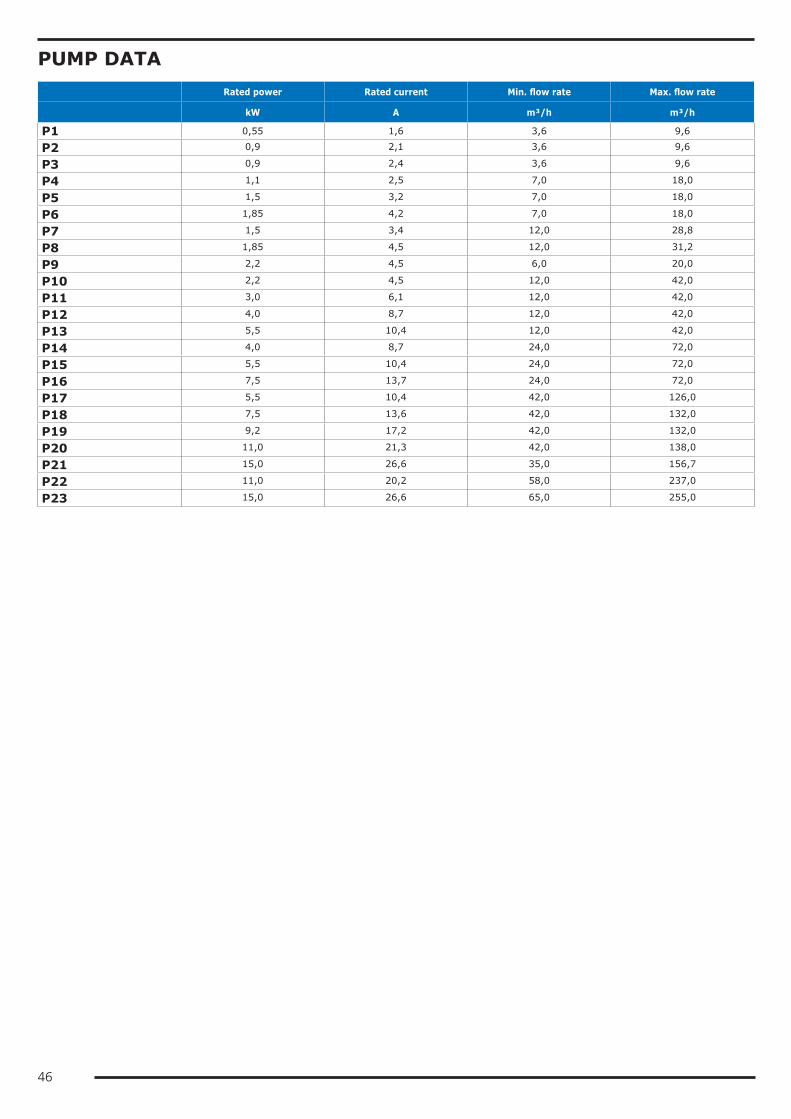
46
PUMP DATA Rated power Rated current Min. flow rate Max. flow rate
kW A m³/h m³/h
P1 0,55 1,6 3,6 9,6
P2 0,9 2,1 3,6 9,6
P3 0,9 2,4 3,6 9,6
P4 1,1 2,5 7,0 18,0
P5 1,5 3,2 7,0 18,0
P6 1,85 4,2 7,0 18,0
P7 1,5 3,4 12,0 28,8
P8 1,85 4,5 12,0 31,2
P9 2,2 4,5 6,0 20,0
P10 2,2 4,5 12,0 42,0
P11 3,0 6,1 12,0 42,0
P12 4,0 8,7 12,0 42,0
P13 5,5 10,4 12,0 42,0
P14 4,0 8,7 24,0 72,0
P15 5,5 10,4 24,0 72,0
P16 7,5 13,7 24,0 72,0
P17 5,5 10,4 42,0 126,0
P18 7,5 13,6 42,0 132,0
P19 9,2 17,2 42,0 132,0
P20 11,0 21,3 42,0 138,0
P21 15,0 26,6 35,0 156,7
P22 11,0 20,2 58,0 237,0
P23 15,0 26,6 65,0 255,0

47
FLOW RATE RANGES OF HEAT EXCHANGERSThe units are sized and optimized for the following nominal conditions:• inlet-outlet of the source-side heat exchanger 30/35°C• inlet-outlet of the user-side heat exchanger 12/7°CThe units can work at design conditions different from nominal conditions, provided that:• the design condition falls within the operating limits specified below• the unit is equipped with all the accessories necessary for operation of the unit (e.g. brine kit, condensation control)• the flow rate at design conditions (that is, of the specific application) must always come within the allowed flow rate
ranges specified below. If the design conditions require a water flow rate that does not come within the allowed operating range, you must contact our sales department that will identify the most suitable solution for the specific application.
TETRIS W REV User-side heat exchanger Source-side heat exchang-
er
Qmin Qmax Qmin Qmax
m³/h m³/h m³/h m³/h
3.2 3,3 9,9 4,0 11,9
4.2 3,7 11,2 4,5 13,5
5.2 4,3 12,9 5,1 15,4
6.2 4,8 14,3 5,7 17,1
7.2 5,5 16,6 6,6 19,8
8.2 6,2 18,6 7,4 22,2
9.2 7,1 21,3 8,4 25,3
10.2 8,6 25,8 10,3 30,8
12.2 9,8 29,3 11,6 34,9
13.2 11,3 33,8 13,4 40,3
15.2 12,5 37,4 14,9 44,6
17.2 13,9 41,6 16,5 49,6
19.2 15,7 47,1 18,8 56,3
20.2 17,2 51,7 20,6 61,9
24.2 19,1 57,4 22,9 68,7
27.2 21,7 65,0 25,9 77,7
30.3 26,7 80,1 32,0 96,0
34.3 29,8 89,4 35,7 107,0
40.3 33,1 99,4 39,7 119,0
18.4 14,0 42,1 16,8 50,4
20.4 17,0 51,0 20,3 61,0
24.4 19,4 58,2 23,2 69,6
26.4 21,8 65,5 26,1 78,4
30.4 24,7 74,2 29,6 88,8
34.4 27,5 82,5 32,9 98,8
38.4 31,4 94,1 37,5 112,6
40.4 35,3 105,8 42,2 126,6
48.4 39,1 117,4 46,9 140,6
54.4 44,2 132,7 52,8 158,5
56.6 47,0 140,9 56,3 168,8
60.6 53,0 159,1 63,5 190,4
TETRIS W REV HP User-side heat exchanger Source-side heat exchang-
er
Qmin Qmax Qmin Qmax
m³/h m³/h m³/h m³/h
3.2 3,0 9,0 3,7 11,0
4.2 3,5 10,4 4,2 12,7
5.2 3,7 11,2 4,6 13,7
6.2 4,4 13,1 5,3 15,9
7.2 5,1 15,4 6,2 18,6
8.2 5,9 17,7 7,1 21,3
9.2 6,6 19,7 8,0 24,0
10.2 7,7 23,0 9,4 28,1
12.2 8,7 26,2 10,7 32,1
13.2 9,9 29,6 12,0 36,1
15.2 11,1 33,4 13,6 40,8
17.2 12,4 37,2 15,1 45,4
19.2 14,2 42,6 17,3 52,0
20.2 16,0 47,9 19,5 58,5
24.2 17,7 53,2 21,7 65,1
27.2 20,4 61,2 24,8 74,3
30.3 24,4 73,2 29,6 88,9
34.3 26,8 80,4 32,6 97,9
40.3 30,1 90,3 36,6 109,8
18.4 13,0 39,1 15,8 47,5
20.4 15,5 46,4 18,9 56,6
24.4 17,6 52,8 21,4 64,3
26.4 19,8 59,5 24,1 72,4
30.4 23,2 69,5 28,0 83,9
34.4 24,1 72,4 29,6 88,9
38.4 28,3 84,9 34,5 103,5
40.4 31,4 94,3 38,5 115,5
48.4 35,3 106,0 43,3 129,9
54.4 40,1 120,4 49,0 147,0
56.6 42,4 127,2 51,8 155,3
60.6 47,2 141,7 57,7 173,1

48
TETRIS W REV OH User-side heat exchanger Source-side heat exchang-
er
Qmin Qmax Qmin Qmax
m³/h m³/h m³/h m³/h
3.2 3,6 10,8 2,8 8,3
4.2 4,1 12,3 3,2 9,5
5.2 4,5 13,4 3,5 10,4
6.2 5,2 15,6 4,1 12,2
7.2 6,0 17,9 4,6 13,8
8.2 6,7 20,0 5,1 15,4
9.2 7,6 22,8 5,9 17,7
10.2 9,2 27,6 7,1 21,4
12.2 10,4 31,2 8,1 24,2
13.2 11,7 35,0 9,1 27,2
15.2 13,3 40,0 10,4 31,2
17.2 14,8 44,5 11,5 34,6
19.2 16,8 50,4 13,1 39,2
20.2 18,5 55,5 14,3 42,9
24.2 20,7 62,0 15,9 47,7
27.2 23,3 69,8 18,0 53,9
30.3 29,0 87,1 22,6 67,9
34.3 33,0 99,1 25,6 76,9
40.3 36,7 110,1 28,6 85,7
18.4 15,1 45,2 11,7 35,1
20.4 18,2 54,7 14,2 42,6
24.4 20,8 62,3 16,2 48,5
26.4 23,3 69,9 18,1 54,4
30.4 26,5 79,5 20,6 61,9
34.4 29,7 89,0 23,1 69,4
38.4 33,7 101,2 26,2 78,7
40.4 37,9 113,7 29,5 88,5
48.4 42,5 127,5 32,7 98,0
54.4 47,5 142,4 36,7 110,2
56.6 50,7 152,0 39,4 118,2
60.6 57,0 171,1 44,4 133,1
TETRIS W REV HPW Evaporator Condenser
Qmin Qmax Qmin Qmax
m³/h m³/h m³/h m³/h
3.2 3,3 9,9 4,0 11,9
4.2 3,7 11,2 4,5 13,5
5.2 4,3 12,9 5,1 15,4
6.2 4,8 14,3 5,7 17,1
7.2 5,5 16,6 6,6 19,8
8.2 6,2 18,6 7,4 22,2
9.2 7,1 21,3 8,4 25,3
10.2 8,6 25,8 10,3 30,8
12.2 9,8 29,3 11,6 34,9
13.2 11,3 33,8 13,4 40,3
15.2 12,5 37,4 14,9 44,6
17.2 13,9 41,6 16,5 49,6
19.2 15,7 47,1 18,8 56,3
20.2 17,2 51,7 20,6 61,9
24.2 19,1 57,4 22,9 68,7
27.2 21,7 65,0 25,9 77,7
30.3 26,7 80,1 32,0 96,0
34.3 29,8 89,4 35,7 107,0
40.3 33,1 99,4 39,7 119,0
18.4 14,0 42,1 16,8 50,4
20.4 17,0 51,0 20,3 61,0
24.4 19,4 58,2 23,2 69,6
26.4 21,8 65,5 26,1 78,4
30.4 24,7 74,2 29,6 88,8
34.4 27,5 82,5 32,9 98,8
38.4 31,4 94,1 37,5 112,6
40.4 35,3 105,8 42,2 126,6
48.4 39,1 117,4 46,9 140,6
54.4 44,2 132,7 52,8 158,5
56.6 47,0 140,9 56,3 168,8
60.6 53,0 159,1 63,5 190,4

49
TETRIS W REV LC User-side heat exchanger
Qmin Qmax
m³/h m³/h
3.2 2,8 8,5
4.2 3,2 9,7
5.2 3,5 10,6
6.2 4,1 12,4
7.2 4,7 14,2
8.2 5,3 15,9
9.2 6,1 18,3
10.2 7,4 22,2
12.2 8,4 25,3
13.2 9,5 28,4
15.2 10,8 32,3
17.2 12,0 35,9
19.2 13,6 40,8
20.2 14,8 44,4
24.2 16,3 49,0
27.2 18,4 55,2
30.3 23,8 71,5
34.3 26,9 80,8
40.3 29,8 89,5
18.4 12,2 36,6
20.4 14,8 44,4
24.4 16,8 50,3
26.4 18,9 56,8
30.4 21,5 64,5
34.4 24,0 72,0
38.4 27,6 82,8
40.4 30,8 92,4
48.4 33,7 101,1
54.4 37,8 113,5
56.6 40,8 122,3
60.6 45,9 137,8
TETRIS W REV LC/HP User-side heat exchanger
Qmin Qmax
m³/h m³/h
3.2 3,0 9,1
4.2 3,5 10,5
5.2 3,8 11,4
6.2 4,4 13,3
7.2 5,2 15,6
8.2 5,9 17,7
9.2 6,6 19,7
10.2 7,7 23,0
12.2 8,8 26,4
13.2 9,9 29,7
15.2 11,2 33,5
17.2 12,4 37,2
19.2 14,2 42,6
20.2 16,0 48,0
24.2 17,7 53,2
27.2 20,4 61,2
30.3 24,4 73,2
34.3 26,8 80,4
40.3 30,1 90,3
18.4 13,0 39,1
20.4 15,5 46,4
24.4 17,6 52,8
26.4 19,8 59,5
30.4 23,2 69,5
34.4 24,1 72,4
38.4 28,3 84,9
40.4 31,4 94,3
48.4 35,3 106,0
54.4 40,1 120,4
56.6 42,4 127,3
60.6 47,2 141,7

50
OPERATING LIMITSTetris W Rev - Tetris W Rev HP - Tetris W Rev OH - Tetris W Rev HPWCOOLING
5
10
15
-10
-5
0
20
25
LWTu
[°C]
20 25 30 35 40 45 50 55 60LWTs [°C]BK
HEATING
35
40
45
20
25
30
50
55
60
65
LWTu
[°C]
-15 -10 -5 0 5 10 15 20 25LWTs [°C]
TOTAL RECOVERY
5
10
15
-10
-5
0
20
25
LWTu
[°C]
20 25 30 35 40 45 50 55 60LWTr [°C]BK
LWTs: water outlet temperature from the source-side heat exchangerLWTu: water outlet temperature from the user-side heat exchangerLWTr: water outlet temperature from the recovery exchangerBK: For LWTu below +3°C, it is mandatory to fit the "Brine Kit" accessory For LWTu below +5°C, it is compulsory to use suitable percentages of antifreeze additives (glycols) to prevent ice formation in the exchanger.For LWTs below +5°C, it is compulsory to use suitable percentages of antifreeze additives (glycols) to prevent ice formation in the heat exchanger.The inlet and outlet temperatures of the user-side exchanger must be given on ordering to allow correct setting of the alarm parame-ters and verification of the sizing of the expansion valve.The cooling set point can then be changed by the customer in an interval that, compared to the set point given on ordering, ranges from -1K up to the maximum temperature allowed by the above-stated operating limits.The unit will be optimized to work at the set point temperatures given on ordering. For different set points, the cooling capacity pro-vided and the level of efficiency of the machine could decrease and move away from these conditions.

51
Tetris W Rev LC - Tetris W Rev LC/HPCOOLING
5
10
15
-10
-5
0
20
LWTu
[°C]
20 25 30 35 40 45 50 55 6560Tcn [°C]BK
HEATING
35
40
45
20
25
30
50
55
60
65
LWTu
[°C]
-25 -20 -15 -10 -5 0 5 10 2015Tev [°C]
TOTAL RECOVERY
5
10
15
-10
-5
0
20
25
LWTu
[°C]
20 25 30 35 40 45 50 55 60LWTr [°C]BK
Tev: evaporating temperatureTcn: condensing temperatureLWTu: water outlet temperature from the user-side heat exchangerLWTr: water outlet temperature from the recovery exchangerBK: For LWTu below +3°C, it is mandatory to fit the "Brine Kit" accessory For LWTu below +5°C, it is compulsory to use suitable percentages of antifreeze additives (glycols) to prevent ice formation in the exchanger.The inlet and outlet temperatures of the user-side exchanger must be given on ordering to allow correct setting of the alarm parame-ters and verification of the sizing of the expansion valve.The cooling set point can then be changed by the customer in an interval that, compared to the set point given on ordering, ranges from -1K up to the maximum temperature allowed by the above-stated operating limits.The unit will be optimized to work at the set point temperatures given on ordering. For different set points, the cooling capacity pro-vided and the level of efficiency of the machine could decrease and move away from these conditions.
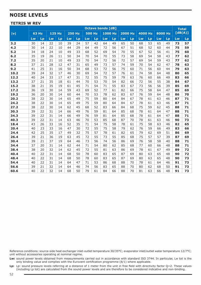
52
NOISE LEVELSTETRIS W REV
|v|Octave bands [dB] Total
[dB(A)]63 Hz 125 Hz 250 Hz 500 Hz 1000 Hz 2000 Hz 4000 Hz 8000 HzLw Lp Lw Lp Lw Lp Lw Lp Lw Lp Lw Lp Lw Lp Lw Lp Lw Lp
3.2 30 14 22 10 39 24 57 42 64 49 65 50 68 53 65 49 73 574.2 30 14 22 10 44 29 64 49 72 56 67 51 68 52 60 44 75 595.2 34 18 24 10 49 33 68 52 69 54 70 55 67 52 56 41 75 606.2 35 19 26 11 50 34 70 54 70 55 73 58 69 54 58 43 77 627.2 35 20 21 10 49 33 70 54 72 56 72 57 69 54 59 43 77 628.2 37 21 28 12 47 31 65 49 73 57 74 59 70 54 62 47 78 639.2 41 25 31 16 50 34 68 53 72 56 75 60 71 56 60 44 79 6310.2 39 24 32 17 46 30 69 54 72 57 76 61 74 58 64 48 80 6512.2 40 24 33 17 47 31 72 55 75 59 79 63 76 60 66 49 83 6613.2 37 21 35 18 61 44 70 53 70 54 82 66 72 56 55 38 84 6715.2 38 21 35 19 61 45 71 54 71 55 83 67 73 56 56 39 85 6917.2 36 19 30 14 59 43 69 52 77 61 82 66 75 58 64 47 85 6919.2 36 20 30 14 60 44 70 53 78 62 83 67 76 59 64 48 86 7020.2 38 22 30 14 65 49 75 59 80 64 84 67 78 61 63 46 87 7124.2 38 22 30 14 65 49 75 59 80 64 84 67 78 61 63 46 87 7127.2 38 22 30 14 62 45 68 52 83 66 84 68 75 59 62 45 88 7130.3 39 22 31 14 66 49 76 59 81 64 85 68 78 61 64 47 88 7134.3 39 22 31 14 66 49 76 59 81 64 85 68 78 61 64 47 88 7140.3 39 22 31 14 63 46 70 53 85 68 87 70 78 61 63 46 90 7318.4 43 26 33 16 52 35 71 54 75 58 78 61 75 58 63 46 82 6520.4 40 23 33 16 47 30 72 55 75 58 79 62 76 59 66 49 83 6624.4 42 25 35 17 49 32 75 57 78 61 82 65 79 62 69 51 86 6926.4 39 21 36 19 63 45 72 55 73 55 85 68 75 57 57 39 87 6930.4 39 21 37 19 64 46 73 56 74 56 86 69 76 58 58 40 88 7134.4 37 20 31 14 62 44 71 54 80 62 85 68 77 60 66 48 88 7138.4 38 20 32 14 62 45 72 55 81 63 86 69 78 61 67 49 89 7240.4 40 22 31 14 68 50 78 60 83 65 87 69 80 63 65 48 90 7248.4 40 22 31 14 68 50 78 60 83 65 87 69 80 63 65 48 90 7354.4 40 22 31 14 64 47 71 53 86 68 88 70 78 61 64 46 91 7356.6 39 21 32 14 64 46 74 56 83 65 88 70 80 62 68 50 91 7360.6 40 22 32 14 68 50 79 61 84 66 88 70 81 63 66 48 91 73
Reference conditions: source-side heat exchanger inlet-outlet temperature 30/35°C; evaporator inlet/outlet water temperature 12/7°C; unit without accessories operating at nominal regime.Lw: sound power levels obtained from measurements carried out in accordance with standard ISO 3744. In particular, Lw tot is the
only binding value and complies with the Eurovent certification programme (8/1) where applicable.Lp: Lp: sound pressure levels referring at a distance of 1 meter from the unit in free field with directivity factor Q=2. These values
(including Lp tot) are calculated from the sound power levels and are therefore to be considered indicative and non-binding.

53
TETRIS W REV /LN
|v|Octave bands [dB] Total
[dB(A)]63 Hz 125 Hz 250 Hz 500 Hz 1000 Hz 2000 Hz 4000 Hz 8000 HzLw Lp Lw Lp Lw Lp Lw Lp Lw Lp Lw Lp Lw Lp Lw Lp Lw Lp
3.2 27 11 20 10 36 20 52 36 58 42 59 43 62 46 58 43 66 504.2 27 12 19 10 40 25 58 43 65 49 60 45 61 46 54 38 68 525.2 30 15 22 10 44 28 61 45 62 47 63 48 60 45 50 35 68 536.2 31 16 23 10 44 29 63 47 63 48 66 50 62 47 52 37 70 557.2 32 16 18 10 44 28 63 47 64 49 65 49 62 47 53 37 70 558.2 33 18 25 10 42 26 58 43 65 50 67 51 62 47 56 41 71 569.2 37 21 28 13 45 30 62 46 65 49 68 52 65 49 54 39 72 5610.2 35 20 29 14 41 26 63 47 65 50 69 53 66 51 57 42 73 5812.2 37 20 30 14 43 27 65 49 68 52 72 55 69 53 60 43 76 5913.2 34 17 32 15 55 39 64 47 64 48 75 58 66 49 50 34 77 6015.2 34 18 32 16 56 40 64 48 65 49 76 60 67 50 51 34 78 6217.2 33 16 27 11 54 38 63 46 70 54 75 59 68 52 58 42 78 6219.2 33 17 28 11 55 38 64 47 71 55 76 60 69 53 59 42 79 6320.2 35 18 28 11 60 43 69 52 73 57 77 60 71 54 57 41 80 6424.2 35 18 28 11 60 43 69 52 73 57 77 60 71 54 57 41 80 6427.2 35 19 28 11 57 40 63 46 76 59 78 61 69 53 57 40 81 6430.3 35 18 28 11 60 43 70 53 74 57 78 61 72 55 58 41 81 6434.3 35 18 28 11 60 43 70 53 74 57 78 61 72 55 58 41 81 6440.3 36 19 28 11 58 41 64 47 78 61 80 63 71 54 58 41 83 6618.4 39 22 30 13 47 30 65 48 68 51 71 54 68 51 57 40 75 5820.4 37 20 30 13 43 26 65 48 68 51 72 55 69 52 60 43 76 5924.4 38 21 32 14 45 28 68 51 71 54 75 57 72 55 62 45 79 6226.4 35 18 33 16 58 40 66 49 67 49 78 61 68 51 52 35 80 6230.4 36 18 34 16 58 41 67 50 68 50 79 62 69 52 53 35 81 6434.4 34 17 29 11 56 39 65 48 73 56 78 61 71 53 60 43 81 6438.4 35 17 29 11 57 40 66 49 74 57 79 62 72 54 61 44 82 6540.4 36 19 29 11 62 45 71 54 76 59 80 62 74 56 60 42 83 6548.4 36 19 29 11 62 45 71 54 76 59 80 62 74 56 60 42 83 6654.4 37 19 29 11 59 41 65 48 79 61 81 63 72 55 59 41 84 6656.6 35 17 30 12 59 41 68 50 76 58 81 63 74 56 63 45 84 6660.6 37 19 29 11 63 45 72 54 77 59 81 63 75 57 60 42 84 66
Reference conditions: source-side heat exchanger inlet-outlet temperature 30/35°C; evaporator inlet/outlet water temperature 12/7°C; unit without accessories operating at nominal regime.Lw: sound power levels obtained from measurements carried out in accordance with standard ISO 3744. In particular, Lw tot is the
only binding value and complies with the Eurovent certification programme (8/1) where applicable.Lp: Lp: sound pressure levels referring at a distance of 1 meter from the unit in free field with directivity factor Q=2. These values
(including Lp tot) are calculated from the sound power levels and are therefore to be considered indicative and non-binding.
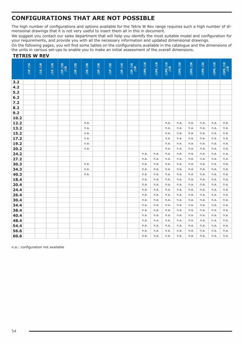
54
CONFIGURATIONS THAT ARE NOT POSSIBLEThe high number of configurations and options available for the Tetris W Rev range requires such a high number of di-mensional drawings that it is not very useful to insert them all in this in document.We suggest you contact our sales department that will help you identify the most suitable model and configuration for your requirements, and provide you with all the necessary information and updated dimensional drawings.On the following pages, you will find some tables on the configurations available in the catalogue and the dimensions of the units in various set-ups to enable you to make an initial assessment of the overall dimensions.
TETRIS W REV
/1P
/1S
/1S
/1R
/1P
/1R
/1P
/1S
/1R
/2P
/2S
/2S
/2R
/2P
/2R
/1P
/2S
/2P
/1S
/2P
/1S
/1R
/1PS
/1S
/1PS
/1R
/1PS
/1S
/1
R
/2PS
/2S
/2PS
/2R
/1PS
/2S
/2PS
/1S
/2PS
/1S
/1
R
3.2
4.2
5.2
6.2
7.2
8.2
9.2
10.2
12.2 n.a. n.a. n.a. n.a. n.a. n.a. n.a.
13.2 n.a. n.a. n.a. n.a. n.a. n.a. n.a.
15.2 n.a. n.a. n.a. n.a. n.a. n.a. n.a.
17.2 n.a. n.a. n.a. n.a. n.a. n.a. n.a.
19.2 n.a. n.a. n.a. n.a. n.a. n.a. n.a.
20.2 n.a. n.a. n.a. n.a. n.a. n.a. n.a.
24.2 n.a. n.a. n.a. n.a. n.a. n.a. n.a. n.a.
27.2 n.a. n.a. n.a. n.a. n.a. n.a. n.a. n.a.
30.3 n.a. n.a. n.a. n.a. n.a. n.a. n.a. n.a. n.a.
34.3 n.a. n.a. n.a. n.a. n.a. n.a. n.a. n.a. n.a.
40.3 n.a. n.a. n.a. n.a. n.a. n.a. n.a. n.a. n.a.
18.4 n.a. n.a. n.a. n.a. n.a. n.a. n.a. n.a.
20.4 n.a. n.a. n.a. n.a. n.a. n.a. n.a. n.a.
24.4 n.a. n.a. n.a. n.a. n.a. n.a. n.a. n.a.
26.4 n.a. n.a. n.a. n.a. n.a. n.a. n.a. n.a.
30.4 n.a. n.a. n.a. n.a. n.a. n.a. n.a. n.a.
34.4 n.a. n.a. n.a. n.a. n.a. n.a. n.a. n.a.
38.4 n.a. n.a. n.a. n.a. n.a. n.a. n.a. n.a.
40.4 n.a. n.a. n.a. n.a. n.a. n.a. n.a. n.a.
48.4 n.a. n.a. n.a. n.a. n.a. n.a. n.a. n.a.
54.4 n.a. n.a. n.a. n.a. n.a. n.a. n.a. n.a.
56.6 n.a. n.a. n.a. n.a. n.a. n.a. n.a. n.a.
60.6 n.a. n.a. n.a. n.a. n.a. n.a. n.a. n.a.
n.a.: configuration not available

55
TABLES OF DIMENSIONSUnits without hydraulic modules
BASE
- O
H -
H
PW /DS
/DC
HP
HP
/DS
LC
LC /
DC
LC/H
P
LC/H
P /D
S
3.2 2A 2A 2A 2A 2A 2A 2A 2A 2A
4.2 2A 2A 2A 2A 2A 2A 2A 2A 2A
5.2 2A 2A 2A 2A 2A 2A 2A 2A 2A
6.2 2A 2A 2A 2A 2A 2A 2A 2B 2B
7.2 2A 2A 2A 2A 2A 2A 2A 2B 2B
8.2 2A 2A 2A 2A 2A 2A 2A 2B 2B
9.2 2A 2A 2A 2A 2A 2A 2A 2B 2B
10.2 2A 2A 2A 2A 2A 2A 2A 2B 2B
12.2 2B 2B 2B 2B 2B 2B 2B 2B 2B
13.2 2B 2B 2B 2B 2B 2B 2B 2B 2B
15.2 2B 2B 2B 2B 2B 2B 2B 2B 2B
17.2 2B 2B 2B 2B 2B 2B 2B 2B 2B
19.2 2B 2B 2B 2B 2B 2B 2B 2B 2B
20.2 2B 2B 2B 2B 2B 2B 2B 2B 2B
24.2 2B 2B 3A 3A 3A 2B 3A 3A 3A
27.2 2B 2B 3A 3A 3A 2B 3A 3A 3A
30.3 3A 4A 4A 3A 4A 3A 4A 3A 4A
34.3 3A 4A 4A 3A 4A 3A 4A 3A 4A
40.3 3A 4A 4A 3A 4A 3A 4A 3A 4A
18.4 3A 3A 3A 3A 3A 3A 3A 3A 3A
20.4 3A 3A 3A 3A 3A 3A 3A 3A 3A
24.4 4A 4A 4A 4A 4A 4A 4A 4A 4A
26.4 4A 4A 4A 4A 4A 4A 4A 4A 4A
30.4 4A 4A 4A 4A 4A 4A 4A 4A 4A
34.4 4A 4A 4A 4A 4A 4A 4A 4A 4A
38.4 4A 4A 4A 4A 4A 4A 4A 4A 4A
40.4 4A 4A 4A 4A 4A 4A 4A 4A 4A
48.4 4A 4A 4A 4A 4A 4A 4A 4A 4A
54.4 4A 4A 4A 4A 4A 4A 4A 4A 4A
56.6 6A 6A 6A 6A 6A 6A 6A 6A n.a.
60.6 6A 6A 6A 6A 6A 6A 6A 6A n.a.
n.a.: configuration not available
Legenda Length Depth Height
2A 1633 792 967
2B 1633 792 1880
2C 2917 792 1880
3A 2017 872 1880
3B 3685 872 1880
3C 3301 872 1880
4A 2834 872 1880
4B 4502 872 1880
6A 3334 872 1880
6B 5002 872 1880

56
Units with hydraulic modules, without tank
BASE
- O
H -
H
PW /DS
/DC
HP
HP
/DS
LC
LC /
DC
LC/H
P
LC/H
P /D
S
3.2 2B 2B 2B 2B 2B 2B 2B 2B 2B
4.2 2B 2B 2B 2B 2B 2B 2B 2B 2B
5.2 2B 2B 2B 2B 2B 2B 2B 2B 2B
6.2 2B 2B 2B 2B 2B 2B 2B 2B 2B
7.2 2B 2B 2B 2B 2B 2B 2B 2B 2B
8.2 2B 2B 2B 2B 2B 2B 2B 2B 2B
9.2 2B 2B 2B 2B 2B 2B 2B 2B 2B
10.2 2B 2B 2B 2B 2B 2B 2B 2B 2B
12.2 2C 2C 2C 2C 2C 2C 2C 2C 2C
13.2 2C 2C 2C 2C 2C 2C 2C 2C 2C
15.2 2C 2C 2C 2C 2C 2C 2C 2C 2C
17.2 2C 2C 2C 2C 2C 2C 2C 2C 2C
19.2 2C 2C 2C 2C 2C 2C 2C 2C 2C
20.2 2C 2C 2C 2C 2C 2C 2C 2C 2C
24.2 2C 2C 3C 3C 3C 2C 3C 3C 3C
27.2 2C 2C 3C 3C 3C 2C 3C 3C 3C
30.3 3B 4B 4B 3B 4B 3B 4B 3B 4B
34.3 3B 4B 4B 3B 4B 3B 4B 3B 4B
40.3 3B 4B 4B 3B 4B 3B 4B 3B 4B
18.4 3C 3C 3C 3C 3C 3C 3C 3C 3C
20.4 3C 3C 3C 3C 3C 3C 3C 3C 3C
24.4 4B 4B 4B 4B 4B 4B 4B 4B 4B
26.4 4B 4B 4B 4B 4B 4B 4B 4B 4B
30.4 4B 4B 4B 4B 4B 4B 4B 4B 4B
34.4 4B 4B 4B 4B 4B 4B 4B 4B 4B
38.4 4B 4B 4B 4B 4B 4B 4B 4B 4B
40.4 4B 4B 4B 4B 4B 4B 4B 4B 4B
48.4 4B 4B 4B 4B 4B 4B 4B 4B 4B
54.4 4B 4B 4B 4B 4B 4B 4B 4B 4B
56.6 6B 6B 6B 6B 6B 6B 6B 6B n.a.
60.6 6B 6B 6B 6B 6B 6B 6B 6B n.a.
n.a.: configuration not available
Legenda Length Depth Height
2A 1633 792 967
2B 1633 792 1880
2C 2917 792 1880
3A 2017 872 1880
3B 3685 872 1880
3C 3301 872 1880
4A 2834 872 1880
4B 4502 872 1880
6A 3334 872 1880
6B 5002 872 1880

57
Units with hydraulic modules and with tank
BASE
- O
H -
H
PW /DS
/DC
HP
HP
/DS
LC
LC /
DC
LC/H
P
LC/H
P /D
S
3.2 2C 2C 2C 2C 2C 2C 2C 2C 2C
4.2 2C 2C 2C 2C 2C 2C 2C 2C 2C
5.2 2C 2C 2C 2C 2C 2C 2C 2C 2C
6.2 2C 2C 2C 2C 2C 2C 2C 2C 2C
7.2 2C 2C 2C 2C 2C 2C 2C 2C 2C
8.2 2C 2C 2C 2C 2C 2C 2C 2C 2C
9.2 2C 2C 2C 2C 2C 2C 2C 2C 2C
10.2 2C 2C 2C 2C 2C 2C 2C 2C 2C
12.2 2C 2C 2C 2C 2C 2C 2C 2C 2C
13.2 2C 2C 2C 2C 2C 2C 2C 2C 2C
15.2 2C 2C 2C 2C 2C 2C 2C 2C 2C
17.2 2C 2C 2C 2C 2C 2C 2C 2C 2C
19.2 2C 2C 2C 2C 2C 2C 2C 2C 2C
20.2 2C 2C 2C 2C 2C 2C 2C 2C 2C
24.2 2C 2C 3C 3C 3C 2C 3C 3C 3C
27.2 2C 2C 3C 3C 3C 2C 3C 3C 3C
30.3 3B n.a. n.a. 3B n.a. 3B n.a. 3B n.a.
34.3 3B n.a. n.a. 3B n.a. 3B n.a. 3B n.a.
40.3 3B n.a. n.a. 3B n.a. 3B n.a. 3B n.a.
18.4 3C 3C 3C 3C 3C 3C 3C 3C 3C
20.4 3C 3C 3C 3C 3C 3C 3C 3C 3C
24.4 4B 4B 4B 4B 4B 4B 4B 4B 4B
26.4 4B 4B 4B 4B 4B 4B 4B 4B 4B
30.4 4B 4B 4B 4B 4B 4B 4B 4B 4B
34.4 4B 4B 4B 4B 4B 4B 4B 4B 4B
38.4 4B 4B 4B 4B 4B 4B 4B 4B 4B
40.4 4B 4B 4B 4B 4B 4B 4B 4B 4B
48.4 4B 4B 4B 4B 4B 4B 4B 4B 4B
54.4 4B 4B 4B 4B 4B 4B 4B 4B 4B
56.6 6B 6B 6B 6B 6B 6B 6B 6B n.a.
60.6 6B 6B 6B 6B 6B 6B 6B 6B n.a.
n.a.: configuration not available
Legenda Length Depth Height
2A 1633 792 967
2B 1633 792 1880
2C 2917 792 1880
3A 2017 872 1880
3B 3685 872 1880
3C 3301 872 1880
4A 2834 872 1880
4B 4502 872 1880
6A 3334 872 1880
6B 5002 872 1880

58
INSTALLATION ADVICEThe units described in this document are, by nature, strongly affected by the characteristics of the system, the working conditions and the installation site.Remember that the unit must be installed by a qualified and skilled technician, and in compliance with the national leg-islation in force in the destination country.The installation must be done in such a way that it will be possible to carry out all routine and non-routine maintenance operations.Before starting any work, you must carefully read the “Installation, operation and maintenance manual” of the machine and do the necessary safety checks to prevent any malfunctioning or hazards.We give some advice below that will allow you to increase the efficiency and reliability of the unit and therefore of the system into which it is inserted.
Water characteristicsTo preserve the life of the exchangers, the water is required to comply with some quality parameters and it is therefore necessary to make sure its values fall within the ranges indicated in the following table:Total hardness 2,0 ÷ 6,0 °fLangelier index - 0,4 ÷ 0,4pH 7,5 ÷ 8,5Electrical conductivity 10÷500 µS/cmOrganic elements -Hydrogen carbonate (HCO3
-) 70 ÷ 300 ppmSulphates (SO4
2-) < 50 ppmHydrogen carbonate / Sulphates (HCO3
-/SO42-) > 1
Chlorides (Cl-) < 50 ppmNitrates (NO3
-) < 50 ppmHydrogen sulphide (H2S) < 0,05 ppmAmmonia (NH3) < 0,05 ppmSulphites (SO3), free chlorine (Cl2) < 1 ppmCarbon dioxide (CO2) < 5 ppmMetal cations < 0,2 ppmManganese ions (Mn++) < 0,2 ppmIron ions ( Fe2+ , Fe3+) < 0,2 ppmIron + Manganese < 0,4 ppmPhosphates (PO4
3-) < 2 ppmOxygen < 0,1 ppm
Installation of water filters on all the hydraulic circuits is obligatory.The supply of the most suitable filters for the unit can be requested as accessory. In this case, the filters are supplied loose and must be installed by the customer following the instructions given in the installation, operation and mainte-nance manual.
Glycol mixturesWith temperatures below 5°C, it is mandatory to work with water and anti-freeze mixtures, and also change the safety devices (anti-freeze, etc.), which must be carried out by qualified authorised personnel or by the manufacturer.Liquid outlet temperature or minimum ambient temperature
°C 0 -5 -10 -15 -20 -25 -30 -35 -40
Freezing point °C -5 -10 -15 -20 -25 -30 -35 -40 -45Ethylene glycol % 6 22 30 36 41 46 50 53 56Propylene glycol % 15 25 33 39 44 48 51 54 57
The quantity of antifreeze should be considered as % on weight

59
Minimum water content in the systemFor correct operation of the unit, it is necessary to ensure a buffering on the system such as to comply with the min-imum operating time considering the greater between the minimum OFF time and the minimum ON time. In short, these contribute to limiting the number of times the compressors are switched on per hour and to preventing undesired deviations from the set point of the delivered water temperature.The following experimental formula allows the minimum water volume of the system to be calculated:
whereVmin is the minimum water content of the system measured in lPtot is the total cooling capacity of the machine measured in kWN is the number of capacity reduction stepsΔΤ is the differential allowed on the water temperature. Unless otherwise specified, this value is considered to be 2.5Kρ is the density of the heat-carrying fluid. Unless otherwise specified, the density of water is considered and therefore 1000kg/m³cp is the specific heat of the heat-carrying fluid. Unless otherwise specified, the specific heat of water is considered and therefore 4.186kJ/(kgK)Considering the use of water and grouping together some terms, the formula can be re-written as follows:
N is equal to the number of compressors installed in the unit.
Installation siteTo determine the best installation site for the unit and its orientation, you should pay attention to the following points:• compliance with the clearance spaces indicated in the official dimensional drawing of the unit must be guaranteed so
as to ensure accessibility for routine and non-routine maintenance operations• you should consider the origin of the hydraulic pipes and their diameters because these affect the radiuses of curva-
ture and therefore the spaces needed for installing them• you should consider the position of the cable inlet on the electrical control panel of the unit as regards the origin of
the power supply• if the installation includes several units side by side, you should consider the position and dimensions of the manifolds
of the heat exchangersOnce the best position for the unit has been identified, you must check that the support slab has the following charac-teristics:• its dimensions must be proportionate to those of the unit: if possible, longer and wider than the unit by at least 30
cm and 15/20cm higher than the surrounding surface• it must be able to bear at least 4 times the operating weight of the unit• must allow the unit to be installed in a level positionThe units are designed and built to reduce to a minimum the level of vibration transmitted to the ground, but it is in any case advisable to use rubber or spring anti-vibration mounts, which are available as accessory and should be requested when ordering.The anti-vibration mounts must be fixed to the machine before positioning the unit on the ground.

60


TC_0
000_
TWR
_EN
_Rev
00_2
0170
209
Blue Box Group S.r.l.Via Valletta, 5 - 30010Cantarana di Cona, (VE) Italy - T. +39 0426 921111 - F. +39 0426 302222www.blueboxcooling.com - [email protected]
Blue Box Group S.r.l. a socio unico - P.IVA 02481290282Company directed and coordinated by Investment Latour (Sweden)