that which does not stabilize, - berkeley robotics and...
TRANSCRIPT


That which does not stabilize, will only make us stronger.
H. Kazerooni, R. Steger Department of Mechanical Engineering
University of California, Berkeley Berkeley, CA 94720, USA
Abstract − The Berkeley Lower Extremity Exoskeleton (BLEEX) is a load-carrying and energetically autonomous human exoskeleton that, in this first generation prototype, carries up to a 34 kg (75 lb) payload for the pilot and allows the pilot to walk at up to 1.3 m/s (2.9 mph). This article focuses on the human-in-the-loop control scheme and the novel ring-based networked control architecture (ExoNET) that together enable BLEEX to support payload while safely moving in concert with the human pilot. The BLEEX sensitivity amplification control algorithm proposed here increases the closed loop system sensitivity to its wearer’s forces and torques without any measurement from the wearer (such as force, position, or electromyogram signal). The tradeoffs between not having sensors to measure human variables, the need for dynamic model accuracy, and robustness to parameter uncertainty are described. ExoNET provides the physical network on which the BLEEX control algorithm runs. The ExoNET control network guarantees strict determinism, optimized data transfer for small data sizes, and flexibility in configuration. Its features and application on BLEEX are described.
I. INTRODUCTION
The goal of the exoskeleton project at U.C. Berkeley is to develop fundamental technologies associated with the design and control of energetically autonomous lower extremity exoskeletons that augment human strength and endurance during locomotion. The first generation lower extremity exoskeleton (commonly referred to as BLEEX) is comprised of two powered anthropomorphic legs, a power unit, and a backpack-like frame on which a variety of heavy loads can be mounted. This system provides its pilot (i.e. the wearer) the ability to carry significant loads on his/her back with minimal effort over any type of terrain. BLEEX allows the pilot to comfortably squat, bend, swing from side to side, twist, and walk on ascending and descending slopes, while also offering the ability to step over and under obstructions while

carrying equipment and supplies. Because the pilot can carry significant loads for extended periods of time without reducing his/her agility, physical effectiveness increases significantly with the aid of this class of lower extremity exoskeletons.
BLEEX has numerous potential applications; it can provide soldiers, disaster relief workers, wildfire fighters, and other emergency personnel the ability to carry heavy loads such as food, rescue equipment, first-aid supplies, communications gear, and weaponry, without the strain typically associated with demanding labor. Unlike unrealistic fantasy-type concepts fueled by movie-makers and science-fiction writers, the lower extremity exoskeleton conceived at Berkeley is a practical, intelligent, load-carrying robotic device. BLEEX was first unveiled in 2004, at U.C. Berkeley’s Human Engineering and Robotics Laboratory (Fig. 1). In this initial model, BLEEX offered a carrying capacity of 34 kg (75 lbs), with weight in excess of that allowance being supported by the pilot.
The effectiveness of the lower extremity exoskeleton is a direct result of the control system’s ability to leverage the human intellect to provide balance, navigation, and path-planning while ensuring that the exoskeleton actuators provide most of the strength necessary for supporting payload and walking. In operation, the exoskeleton becomes transparent to the pilot and there is no need to train or learn any type of interface to use the robot. The control algorithm ensures that the exoskeleton always moves in concert with the pilot with minimal interaction force between the two and was first presented in [1].
The control scheme needs no direct measurements from the pilot or the human-machine interface (e.g. no force sensors between the two); instead, the controller estimates, based on measurements from the exoskeleton structure only, how to move so that the pilot feels very little force. This control scheme is an effective method of generating locomotion when the contact location between the pilot and the exoskeleton is unknown and unpredictable (i.e. the exoskeleton and the pilot are in contact in variety of places). This control method differs from compliance control methods employed for upper extremity exoskeletons
Fig. 1 Berkeley Lower Extremity Exoskeleton (BLEEX) first generation prototype and pilot. 1: Hydraulic power supply and payload occupy the upper
portion of the backpack; 2: Rigid BLEEX spine connected to the flexible pilot vest; 3: Central control computer
occupies the lower portion of the backpack; 4: Some of the hydraulic
actuators (ankle, knee and hip); 5: Two of the control network’s Remote I/O
Modules (RIOM); 6: Rigid connection of the BLEEX feet to the pilot’s boots.
More photographs can be found at http://bleex.me.berkeley.edu

[2], and haptic systems [3,4] because it requires no force sensor between the wearer and the exoskeleton.
The basic principle for the control of BLEEX rests on the notion that the exoskeleton needs to shadow the wearer’s voluntary and involuntary movements quickly, and without delay. This requires a high level of sensitivity in response to all forces and torques on the exoskeleton, particularly the forces imposed by the pilot. Addressing this need involves a direct conflict with control science’s goal of minimizing system sensitivity in the design of a closed loop feedback system. If fitted with a low sensitivity, the exoskeleton would not move in concert with its wearer. We realize, however, that maximizing system sensitivity to external forces and torques leads to a loss of robustness in the system.
Taking into account this new approach, our goal was to develop a control system for BLEEX with high sensitivity. We were faced with two realistic concerns; the first was that an exoskeleton with high sensitivity to external forces and torques would respond to other external forces not initiated by its pilot. The key to stabilizing the exoskeleton and preventing it from falling in response to external forces depends on the pilot’s ability to move quickly (e.g. step back or sideways) to create a stable situation for himself and the exoskeleton. For this, a very wide control bandwidth is needed so the exoskeleton can respond to both pilot’s voluntary and involuntary movements (i.e. reflexes).
The second concern is that systems with high sensitivity to external forces and torques are not robust to variations and therefore the precision of the system performance will be proportional to the precision of the exoskeleton dynamic model. Although this is a serious drawback, we have accepted it as unavoidable. Nevertheless, various experimental systems in our laboratory have proved the overall effectiveness of the control method in shadowing the pilot’s movement.
Realization of this control scheme requires a high-performance physical control architecture. This paper presents the ring-based protocol and distributed networked control hardware called the ExoNet. Traditional centralized control architectures where a supervisory controller directly interfaces in a point-to-point fashion with all sensors and actuators in the system have been successfully implemented in the past. They are generally feasible when a controller interfaces with small number of sensors and actuators and requires short wiring to them. Larger sophisticated multi-degree-of-freedom systems frequently require the control network to be compact, easily reconfigurable, expandable, and maintainable. Hence, we utilized a networked control system (NCS) as an alternative to the conventional centralized control system because of its advantages in flexibility, volume of wiring and capacity of distribution [5].
II.PREVIOUS WORK
In our research work at U.C. Berkeley, we have divided the technology associated with human power augmentation into lower extremity exoskeletons and upper extremity exoskeletons. The reason for this was two-fold; firstly, we could envision a great many applications for either a stand-alone lower or upper extremity exoskeleton in the immediate future. Secondly, and more importantly for the separation, is that the

exoskeletons are in their early stages, and further research still needs to be conducted to ensure that the upper extremity exoskeleton and lower extremity exoskeleton can function well independently before we can venture an attempt to integrate them. See [6,7] for research work on upper extremity exoskeletons at Berkeley.
The concept of a powered human-assistive exoskeleton has been explored in various reach projects since the 1950’s, though recent advances in controls and computation have generated renewed interest (see [8-11]). A recent notable project is the “RoboKnee,” which is a powered knee brace that functions in parallel to the wearer’s knee but does not transfer loads to the ground [12]. This device transfers the weight of the backpack payload onto the human skeleton (including shanks, ankles, and feet). “HAL”, a walking aid system for individuals with gait disorders, is another current exoskeleton-like device in that it adds to the force generated by the human muscles but relies on the human skeleton to transfer loads [13]. BLEEX draws on this history of exoskeleton development but is unique in that it mechanically functions as a true load bearing exoskeleton, is energetically autonomous, and utilizes a unique control system that does not require any direct measurements on the human.
Networked control systems (NCSs), such as the one developed for BLEEX, have broad applications beyond just exoskeleton control and have been adopted in fields related to industrial automation, building automation, office and home automation, intelligent vehicles, aircrafts, and spacecrafts [14-18]. Several network types had been developed based upon the applications, such as a process field bus (PROFIBUS) [19], manufacturing automation protocol (MAP) [20], and fiber distributed data interface (FDDI) [21]. EtherNet, ControlNet, and DeviceNet are some other common NCSs that are compared as control networks in different situations and schemes in [5].
III. SENSITIVITY AMPLIFICATION CONTROLLER
A. A simple One Degree-of-Freedom (DOF) Example The control of the exoskeleton is explained
here through the 1 DOF example shown in Error! Reference source not found.. This figure schematically depicts a human leg attached and interacting with a 1 DOF exoskeleton leg in a swing configuration (no interaction with the ground). For simplicity, the exoskeleton leg is shown as a rigid link pivoting about a joint and powered by a single actuator. The exoskeleton leg in this example has an actuator that produces a torque, r, about pivot point A.
Although the pilot is attached securely to the exoskeleton at the foot, other parts of the pilot leg, such as the shanks and thighs, can contact the exoskeleton and impose forces and torques on the exoskeleton leg. The location of the contacts and the direction of the contact forces (and sometimes contact torques) vary and are therefore considered unknown values in this analysis. In fact, one of the primary objectives in designing
,r dA
,r dA
Fig. 2 One DOF conceptual model of an
exoskeleton leg interacting with
the pilot’s leg.
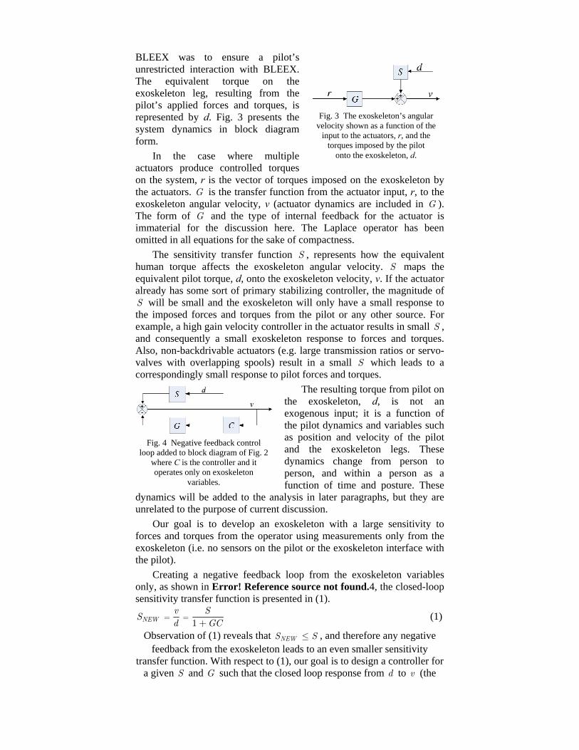
BLEEX was to ensure a pilot’s unrestricted interaction with BLEEX. The equivalent torque on the exoskeleton leg, resulting from the pilot’s applied forces and torques, is represented by d. Fig. 3 presents the system dynamics in block diagram form.
In the case where multiple actuators produce controlled torques on the system, r is the vector of torques imposed on the exoskeleton by the actuators. G is the transfer function from the actuator input, r, to the exoskeleton angular velocity, v (actuator dynamics are included in G ). The form of G and the type of internal feedback for the actuator is immaterial for the discussion here. The Laplace operator has been omitted in all equations for the sake of compactness.
The sensitivity transfer function S , represents how the equivalent human torque affects the exoskeleton angular velocity. S maps the equivalent pilot torque, d, onto the exoskeleton velocity, v. If the actuator already has some sort of primary stabilizing controller, the magnitude of
will be small and the exoskeleton will only have a small response to the imposed forces and torques from the pilot or any other source. For example, a high gain velocity controller in the actuator results in small S , and consequently a small exoskeleton response to forces and torques. Also, non-backdrivable actuators (e.g. large transmission ratios or servo-valves with overlapping spools) result in a small S which leads to a correspondingly small response to pilot forces and torques.
S
The resulting torque from pilot on the exoskeleton, d, is not an exogenous input; it is a function of the pilot dynamics and variables such as position and velocity of the pilot and the exoskeleton legs. These dynamics change from person to person, and within a person as a function of time and posture. These
dynamics will be added to the analysis in later paragraphs, but they are unrelated to the purpose of current discussion.
Our goal is to develop an exoskeleton with a large sensitivity to forces and torques from the operator using measurements only from the exoskeleton (i.e. no sensors on the pilot or the exoskeleton interface with the pilot).
Creating a negative feedback loop from the exoskeleton variables only, as shown in Error! Reference source not found.4, the closed-loop sensitivity transfer function is presented in (1).
Fig. 3 The exoskeleton’s angular velocity shown as a function of the
input to the actuators, r, and the torques imposed by the pilot
onto the exoskeleton, d.
Fig. 4 Negative feedback control loop added to block diagram of Fig. 2
where C is the controller and it operates only on exoskeleton
variables.
1NEWv S
Sd G
= =+ C
S
(1)
Observation of (1) reveals that , and therefore any negative feedback from the exoskeleton leads to an even smaller sensitivity
transfer function. With respect to (1), our goal is to design a controller for a given S and G such that the closed loop response from d to v (the
NEWS ≤

new sensitivity function as given by (1)) is greater than the open loop sensitivity transfer function (i.e.S ) within some bounded frequency
range. This design specification is given by inequality (2). NEWS S> (2) (0, oω ω∀ ∈ )
or alternatively 1 1GC+ < (3) (0, oω ω∀ ∈ )where is the exoskeleton maneuvering bandwidth. oω
Exoskeleton control requires a totally opposite goal from classical and modern control theory: maximize the sensitivity of the closed loop system to forces and torques. In classical servo problems, negative feedback loops with large gains result in small sensitivity within a bandwidth, which means that they reject forces and torques (usually called disturbances). However, the above analysis states that the exoskeleton controller needs a large sensitivity to forces and torques.
The exoskeleton controller uses the inverse of the exoskeleton dynamics as a positive feedback such that the loop gain for the exoskeleton approaches unity from below (slightly less than 1), which can be written as:
1NEWv SSd G
= =− C
S
)
(4)
where C is chosen as (5) ( )1 11C Gα− −= −and is the amplification number greater than unity. α
If , then , and the new sensitivity transfer function is (ten times the force amplification). Equation (5) simply states that a positive feedback controller needs to be chosen as the inverse dynamics of the system dynamics scaled down by . Note that (5) prescribes the controller in the absence of unmodeled high-frequency exoskeleton dynamics. In practice, C also includes a unity gain low pass filter to attenuate the unmodeled high-frequency exoskeleton dynamics that may not be captured in the model, .
10α = 10.9C G−=10NEWS =
11( α−−
1G −
The success of this control method is dependant on the accuracy of system model (i.e. ) which governs how much torque is needed at each joint to compensate for the payload and dynamics of the exoskeleton. Models errors which cause the exoskeleton to apply too little actuation torque mean that the pilot would feel a portion of the payload. Errors which cause over-actuation however, could lead to instability. This straightforward control solution comes with an expensive price: robustness to parameter variations. To get the above method working, one needs to know the dynamics of the system very well. The next section discusses this tradeoff.
1G−
B. Robustness to Parameter Variations The variation in the new positive feedback sensitivity transfer
function (4) is given by (6).
1NEW
NEW
S S GCS S GC
= +∆ ∆
−GG∆ (6)
If GC is close to unity (when the force amplification number, , is large) any parameter variation on modeling will be amplified as well. For example if the parameter uncertainty in the system is about 10%, i.e.:
α

0.10GG∆ = and 0S
S∆ = , then (6) results in
0.101
NEW
NEW
S GCS GC
=∆
− (7)
Now assume C is chosen such that . Substituting into (7) results in
10.9C G−=
0.90NEW
NEW
SS
=∆ (8)
Equation (8) indicates that any parameter variation directly affects the system behavior. In the above example, a 10% error in model parameters results in nine times the variation in the sensitivity function. This is why model accuracy is crucial to exoskeleton control. One can see this problem as a tradeoff: the design approach described above requires no sensor (e.g. force or electromyogram) in the interface between the pilot and the exoskeleton; one can push and pull against the exoskeleton in any direction and at any location without measuring any variables on the interface. However, the control method requires a very good model of the system. At this time, our experiments with BLEEX have shown that this control scheme—which does not stabilize BLEEX—forces the exoskeleton to follow wide-bandwidth human maneuvers while carrying heavy loads.
C. Pilot Dynamics In our control scheme, as will be shown, there is no need to include
the internal components of the pilot limb model; the detailed dynamics of nerve conduction, muscle contraction, and central nervous system processing are implicitly accounted for in constructing the dynamic model of the pilot limbs. For more detail on in-depth modeling and analysis of the internal components of the pilot limb as applied to haptic systems and human power amplifiers, see [22,23] and our preliminary results in [24].
The pilot force on the exoskeleton, d , is a function of both the pilot dynamics, , and the kinematics of the pilot limb (e.g., velocity, position or a combination thereof).
H
( )d H υ= − (9)
The specific form of H is not known other than that it results in the human muscle force on the exoskeleton. In general, H is determined primarily by the physical properties of the human dynamics. Here we assume is a nonlinear operator representing the pilot impedance as a function of the pilot kinematics.
H
Error! Reference source not found.5 represents the closed loop system behavior when pilot dynamics is added to the block diagram of Error! Reference source not found.4. Examining Error! Reference source not found.5 reveals that (4), representing the new exoskeleton sensitivity transfer function from d to v, is not affected by the feedback loop containingH .
Error! Reference source not found.5 shows an important characteristic for human
Fig. 5 The two feedback loops in this diagram represent the overall motion of the human and exoskeleton. The upper feedback loop shows how the pilot moves the exoskeleton through applied forces. The lower positive
feedback loop shows how the controller drives the exoskeleton.
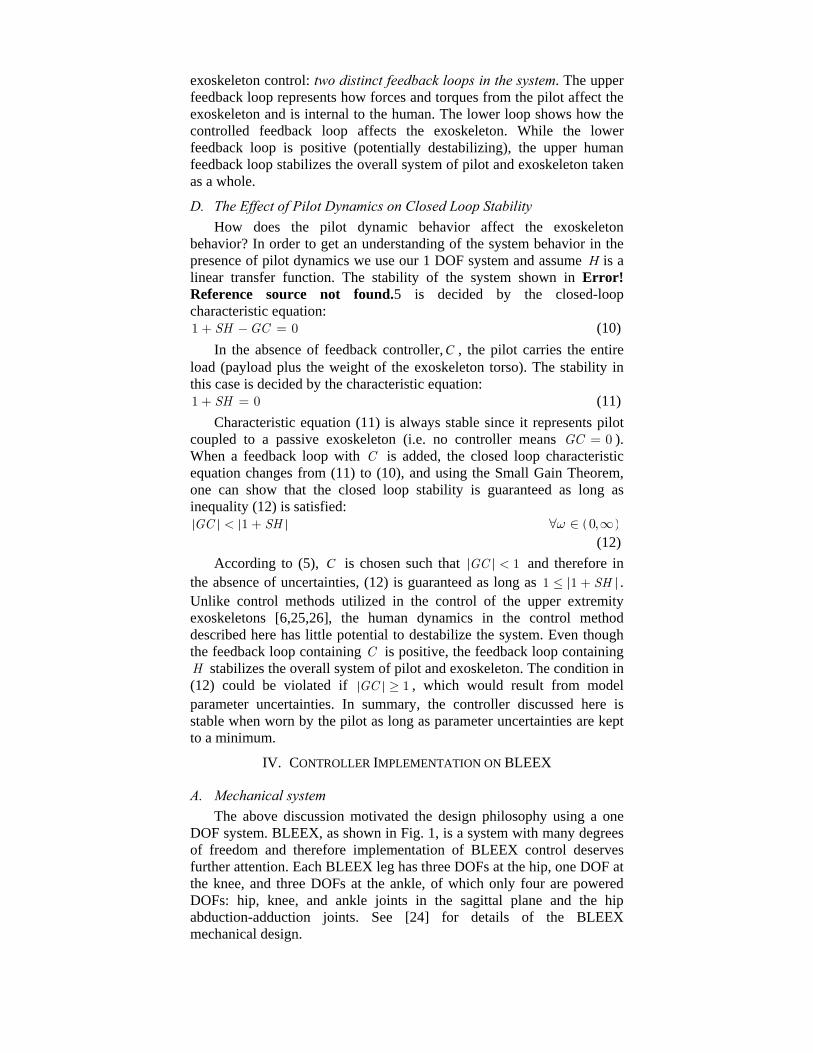
exoskeleton control: two distinct feedback loops in the system. The upper feedback loop represents how forces and torques from the pilot affect the exoskeleton and is internal to the human. The lower loop shows how the controlled feedback loop affects the exoskeleton. While the lower feedback loop is positive (potentially destabilizing), the upper human feedback loop stabilizes the overall system of pilot and exoskeleton taken as a whole.
D. The Effect of Pilot Dynamics on Closed Loop Stability How does the pilot dynamic behavior affect the exoskeleton
behavior? In order to get an understanding of the system behavior in the presence of pilot dynamics we use our 1 DOF system and assume H is a linear transfer function. The stability of the system shown in Error! Reference source not found.5 is decided by the closed-loop characteristic equation: 1 SH GC+ − = 0
0
(10) In the absence of feedback controller, C , the pilot carries the entire
load (payload plus the weight of the exoskeleton torso). The stability in this case is decided by the characteristic equation: 1 SH+ = (11)
Characteristic equation (11) is always stable since it represents pilot coupled to a passive exoskeleton (i.e. no controller means ). When a feedback loop with C is added, the closed loop characteristic equation changes from (11) to (10), and using the Small Gain Theorem, one can show that the closed loop stability is guaranteed as long as inequality (12) is satisfied:
0GC =
1GC SH< + ( )0,ω∀ ∈ ∞ (12)
According to (5), is chosen such that C 1GC < and therefore in the absence of uncertainties, (12) is guaranteed as long as 1 1 SH≤ + . Unlike control methods utilized in the control of the upper extremity exoskeletons [6,25,26], the human dynamics in the control method described here has little potential to destabilize the system. Even though the feedback loop containing C is positive, the feedback loop containing
stabilizes the overall system of pilot and exoskeleton. The condition in (12) could be violated if H
1GC ≥ , which would result from model parameter uncertainties. In summary, the controller discussed here is stable when worn by the pilot as long as parameter uncertainties are kept to a minimum.
IV. CONTROLLER IMPLEMENTATION ON BLEEX
A. Mechanical system The above discussion motivated the design philosophy using a one
DOF system. BLEEX, as shown in Fig. 1, is a system with many degrees of freedom and therefore implementation of BLEEX control deserves further attention. Each BLEEX leg has three DOFs at the hip, one DOF at the knee, and three DOFs at the ankle, of which only four are powered DOFs: hip, knee, and ankle joints in the sagittal plane and the hip abduction-adduction joints. See [24] for details of the BLEEX mechanical design.

The pilot and BLEEX have rigid mechanical connections at the torso and the feet; everywhere else, the pilot and BLEEX have compliant or periodic contact. The connection at the torso is made using an adjustable compliant vest that distributes the forces between BLEEX and the pilot, thereby preventing abrasion. The vest includes a rigid plate (with hole pattern) on the back that bolts to the rigid metal spine of the BLEEX torso.
The pilot’s shoes or boots attach to the BLEEX feet using a modified quick-release binding mechanism similar to snowboard bindings. The binding cleat on the modified pilot boot does not interfere with normal wear when the pilot is unclipped from BLEEX. The BLEEX foot is composed of a rigid heel section with the binding and a compliant, but load bearing, toe section that begins mid foot and extends to the toe. The BLEEX foot has a compressible rubber sole with a tread pattern that provides both shock-absorption and traction while walking. The rubber sole of the BLEEX foot contains multiple embedded pressure sensors (coarse on/off information only), that are used to detect the trajectory of the BLEEX ground reaction force starting from “heel-strike” to “toe-off” in the walking gait cycle. This information is used in the BLEEX controller to identify the BLEEX foot configuration relative to the ground.
BLEEX is powered via a compact portable hybrid output power supply contained in the backpack. Several different portable BLEEX power supplies have been designed by our group for different applications and environments. Each provides hydraulic flow and pressure for the actuators and generates electric power for the sensors, network, and control computer. Details of the design, testing, and performance of the BLEEX power supplies can be found in [27].
B. Dynamic Modeling Although biomechanical studies of walking frequently identify seven or more distinct phases of the human walking gait cycle [28], for simplicity in control we consider BLEEX to have three distinct phases (shown in Error! Reference source not found.6) which manifest to three different dynamic models:
Fig. 6 Three phases of the BLEEX walking cycle.
Single support: one leg is in the stance configuration while another leg is in swing.
Double support: both legs are in stance configuration and situated flat on the ground.
Double support with one redundancy: both legs are in stance configuration, but one leg is situated flat on the ground while the other one is not.
Using the information from the sensors in the foot sole, the controller determines in which phase BLEEX is operating and which of the three dynamic models apply.

In our initial control design process, we decoupled the control of the abduction-adduction DOF at the hip from the control of joints in the sagittal plane. This is valid because we noticed through measurements that the abduction-adduction movements during normal walking (less than 0.9 m/s or 2 mph) are rather slow [29]. In comparison with the movements in the sagittal plane, the abduction-adduction movements can be considered quasi-static maneuvers with little dynamical affects on the rest of system. For the sake of brevity, the following sections describe the control method in the sagittal plane for a given set of abduction-adduction angles.
C. Single Support In the single support phase, BLEEX is
modeled as the seven DOF serial link mechanism in the sagittal plane shown in Error! Reference source not found. 7. The dynamics of BLEEX can be written in the general form as: ( ) ( , ) ( )M C P Tθ θ θ θ θ θ+ + = d+ (13)
where
[ ]1 2 7Tθ θ θ θ= … and T 1 2 60
TT T T⎡ ⎤⎢ ⎥⎣ ⎦= … .
M is a inertia matrix and is a function of , is a centripetal and Coriolis matrix and is a function of and , and P is a
vector of gravitational torques and is a function of θ only. T is the actuator torque vector with its first element set to zero since there is no actuator associated with joint angle (i.e. angle between the BLEEX foot and the ground). is the effective 7 torque vector imposed by the pilot on BLEEX at various locations. According to (5), we choose the controller to be the inverse of the BLEEX dynamics scaled by , where is the amplification number.
7 7×θ ( , )C θ θ 7× 7
θ θ7 1×
7 1×
1θd 1×
1(1 )α−− α
Fig.7 Sagittal plane representation of
BLEEX in the single stance phase.
( )[ ]1ˆ ˆ ˆ( ) 1 ( ) ( , )T P M Cθ α θ θ θ θ θ−= + − +
θ
(14) ˆ( , )C θ θ , and M are the estimates of the Coriolis matrix, gravity
vector, and the inertia matrix respectively for the system shown inˆ( )P θ ˆ( )
Fig. 7. Note that (14) results in a actuator torque. Since there is no actuator between the BLEEX foot and the ground, the torque prescribed by the first element of T must be provided by the pilot. Substituting from (14) into (13) yields,
7 1×
T
( )[ ]1ˆ ˆ ˆ( ) ( , ) ( ) ( ) 1 ( ) ( , )M C P P M Cθ θ θ θ θ θ θ α θ θ θ θ θ−+ + = + − + d+
θ θ=
(15)
In the limit when M M , , , and is sufficiently large, will approach zero, meaning the pilot can walk
as if BLEEX did not exist. However, it can be seen from (15) that the force felt by the pilot is a function of and the accuracy of the estimates
,
ˆ( ) ( ) C( , = C( , ˆ) )θ θ θ θ (θ) (θ)ˆP P=α d
αˆ( , )C θ θ P( )ˆ θ , and M( )ˆ θ . In general, the more accurately the system is
modeled, the less the human force, , will be. In the presence of variations in abduction-adduction angles, only P in equations (13) and (14) needs to be modified.
d(θ)

D. Double Support In the double support phase, both BLEEX feet are flat on the ground.
The exoskeleton is modeled as two planar 3 DOF serial link mechanisms that are connected to each other along their uppermost link as shown in Fig. 8-a. The dynamics for these serial links are represented by (16) and (17). ( ) ( ) ( )L LM + C + = + d, , , ,TL L L TL L L L L TL L L Lm m P m Tθ θ θ θ θ θ (16)
( ) ( ) ( )R RM + C + = + d, , , ,TR R R TR R R R R TR R R Rm m P m Tθ θ θ θ θ θ (17)
where: and L L1 L2 L3θ θ θ θT⎡ ⎤⎢ ⎥⎣ ⎦= R R1 R2 R3θ θ θ θ
T⎡ ⎤⎢ ⎥⎣ ⎦= . and
are effective torso masses supported by each leg and is the total torso mass such that:
TRm TLm
Tm
T TR Tm m m= + L (18)
The contributions of m on each leg (i.e., m and m ) are chosen as functions of the location of the torso center of mass relative to the locations of the ankles such that:
T TL TR
TR TL
TL TR
m xm x
= (19)
where is the horizontal distance between the torso center of mass and the left ankle, and is the horizontal distance between the torso center of mass and the right ankle. For example, if the center of mass of the torso is located directly above the right leg, then m and
. Similar to the single stance phase, the controllers are chosen such that
TLx
TRx
0TL =
,θ
TR Tm m=
L L TL L L TL L L L TL L L LT = P (m ) + (1 - ) M (m ) θ + C (m θ θ1 ˆˆ ˆ , ), ,θ θα− ⎡ ⎤⎢ ⎥⎣ ⎦ (20)
R R TR R R TR R R R TR R R RT = P (m ) + (1 - ) M (m ) θ + C (m θ θ1 ˆˆ ˆ , ), , ,θ θ θα− ⎡ ⎤⎢ ⎥⎣ ⎦ (21)
Needless to say, (19) is valid only for quasi-static conditions where the accelerations and velocities are small. This is in fact the case, since in the double support phase, both legs are on the ground and BLEEX’s angular acceleration and velocities are quite small. This allows us to simplify (20) and (21) during slow walking by removing all terms except the estimates of the gravitational vectors.
E. Double Support with One Redundancy Double support with one redundancy is modeled as a 3 DOF serial
link mechanism for the stance leg with the foot flat on the ground and a 4 DOF serial link mechanism for the stance leg that is not completely on the ground (Fig. 8-b). Each serial link supports a portion of the torso weight. The dynamics for these serial links are similar to (16) and (17), with the exception that the redundant leg equation represents four DOFs as opposed to three. For the specific instant shown in Fig. 8-b, the left leg has 4 DOF and the right leg has 3 DOF.
Fig. 8 Sagittal plane representation of BLEEX in a) the double support phase and
b) the double support phase with one redundancy.

Similar to the double support case, the effective torso mass supported by each leg is computed by (19). Controllers for this case can be chosen in the same manner as (20) and (21). Note that the actuator torque vector associated with the leg that has 4 DOF (e.g. LT for the case shown in Fig. 8-b) is a 4 vector. As in the single support phase, the torque prescribed by the first element of T must be provided by the pilot because there is no actuator between the BLEEX foot and the ground. As the pilot walks, BLEEX transitions through the various phases shown in Error! Reference source not found.6. The foot sole pressure sensors detect which leg has four degrees of freedom and which leg has three degrees of freedom and the controller then chooses the appropriate algorithm for each leg.
Fig. 10 Ring Topology
×1
V. NETWORKED CONTROL SYSTEM
A. Network Structure
Fig. 9 provides global picture of the ExoNET networked control system that hosts the control algorithm. ExoNET was designed for BLEEX to enable the central controller to interact with distributed sensors, reduce the bulk, complexity, and difficulty of wiring, and achieve high-speed real-time control.
ExoNET consists of four ring networks (ExoRing0~3). Each ring has a series of sensor and actuator data aggregation network nodes we call Remote I/O Modules, or RIOMs. Also, an additional network (GuiRing) provides a graphical user interface (GUI) for debugging and can be hot-swapped into the system while the network is running.
These five networks are all served by a central module (ExoBrain) composed of a single board computer (ExoCPU), a PCI Interface Module (ExoPCI) and a Supervisor I/O Module (SIOM). The SIOM is a custom built board that has three independent transceiver channels. Channel 1 contains the two leg network rings: ExoRing0 and ExoRing2. Channel 2 contains the two torso network rings: ExoRing1 and ExoRing3. The third transceiver channel is coupled to GUI network (GuiRing).
The GUI network allows for real-time monitoring and administration of the control system for debugging purposes. The GUI network includes the GUI
RIOM (GuiRIOM), the GUI PCI interface module (GuiPCI) and the GUI computer (GuiPC) inside the GUI computer case. The GuiRIOM and the GuiPCI stack together on a PCI riser card that is plugged into one of PCI slots of the GuiPC.
Fig. 9 Overall view of ExoNET networked control system and external GUI debug terminal.

Fig. 10 shows the ExoNET ring topology of an ExoRing where N RIOMs (Slave 1,2,…N) are serially connected to one SIOM (Master). Each serial link consists of three twisted pairs of wires. While the first and second pairs are used for receiving and transmitting data, the third pair is used for carrying power to RIOMs. The direction of data flow in this network is from the transmit port (TX) of the master node to the receive port (RX) of the Slave 1 node, and from the TX of the Slave 1 node to the RX of the Slave 2 node, and so forth. This path continues to the RX of the Slave N node. A loop-back terminator completes the ring by plugging into the TX of the Slave-N node so that data leaving from the TX of the Slave-N node will arrive at the RX of the SIOM master node after passing through each slave node internal loop line (labeled LP in Fig. 10).
This ring topology provides flexibility and expandability for the network: a user can easily add or remove slave nodes and then plug a loop-back terminator at the last slave node to complete the network. This topology eliminates the requirement of a single circulating serial cable connecting from the last slave node to the master node. It is particularly useful in cabling a network where all nodes are physically oriented on a line (as on the BLEEX legs). In this case, only one serial link cable between any two consecutive nodes and a loop-back terminator on the last node are required to form a complete ring network.
B. Remote I/O Modules (RIOMS) – A Practical Solution to Managing Wiring Complexity
The ExoNET RIOM modules act as smart sensor and control data aggregation nodes. BLEEX is a complex multi-degree of freedom device with a large number of sensor inputs and control outputs. A common approach in robotic design would be to route all sensor and actuator signal wires directly to a central control computer. For BLEEX, this would have meant a total of over 210 wires. By distributing network nodes around the robot, we only require one wire per limb (ring network) to route all sensor and actuation information. Each node takes care of interfacing with the various types of sensors (serial, parallel, analog, digital, etc…) located physically close by it and assembles the data into digital packets that can be transmitted via the network to-from the central computer. In addition, the RIOM can send out analog control signals for actuation (e.g. controlling a hydraulic servo-valve). The distribution and location of RIOMs is generally chosen to achieve a minimum volume of wiring and a reasonable and convenient allocation of sensors and actuators to each RIOM. Each RIOM in the first generation BLEEX provides for: 5 sensor inputs (three
16-bit analog inputs, one
quadrature encoder input, and one 6-bit digital input) and one 16-bit
analog actuation
output. Details of the
electronics hardware
design can be found in [30].
CypressTX/RX
XilinxFPGAUP
DWN
AINAIN
AINAOUT
ENC IN
DIG
IN
ExoNET RIOM
CypressTX/RX
XilinxFPGAUP
DWNUP
DWN
AINAIN
AINAOUT
ENC IN
DIG
IN
ExoNET RIOM
Fig. 11 ExoNET RIOM photo and schematic. Each RIOM provides for 3 analog inputs (AIN), 1 analog output (AOUT), 6
digital inputs (DIG IN), 1 quadrature encoder input (ENC IN), and 2 network communication ports (UP and DWN). Two integrated
circuits handle processing (Xilinx Inc.) and network communication (Cypress Semiconductor Inc.) respectively.

C. Network Protocol
ExoNET network communication consists of passing “messages” around the ring formed by the nodes on the network (SIOM and RIOMs). A message is a series of data packets that is preceded by a chosen start delimiter code (“S” in Fig. 11) and proceeded by a chosen end delimiter code (“E” in Fig. 11). Each data packet in a message includes bits that indicate the source of the packet (e.g. the ID# of a RIOM), the type of data (e.g. error, sensor, actuation command,…), the actual data value, and error checking bits based on a cyclic redundancy check (CRC). Fig 11 shows two types of data packets in the message being passed between nodes: actuator commands sent from the master to the RIOMs (C1, C2), and sensor data destined for the master that was collected by the RIOMs (T11, T12, T21,…).
Each communication cycle in the network protocol (Fig. 11) involves passing a message sequentially from the master node (e.g. a SIOM) to each slave node in the ring network (e.g. the RIOMs) and then returning the message back to the master node. As the message travels around the ring, each RIOM reads its assigned actuator command data packet (by looking for its RIOM ID#), and then appends its collected sensor data to the message. When the message returns to the master, completing the ring, it has grown to include the sensor data from each node in the network. Because the communication cycles occur at a fixed rate set by the control scheme, this protocol allows for deterministic control and provides built in network error detection because every message returning to the master must contain information from each node on the ring.
Testing ExoNET on BLEEX has shown that the network update time (NUT) for a ten RIOM network, passing 140 bytes of data, takes less than 20µs. The controller for BLEEX updates at 2 kHz (500 µs sample time), which leaves 480µs to perform the control algorithm calculations on the ExoCPU. For a more detailed discussion of the BLEEX control network and performance analysis, see [30,31].
Fig. 11 Network communication overview. In a communication cycle, messages (strings of data packets beginning with start delimiter, S, and ending with end delimiter, E) pass from a
aster node (SIOM) to each slave node (RIOM) sequentially andreturn to the master node to complete the ring network
communication
m
message
VI. CONCLUSION
The Berkeley Lower Extremity Exoskeleton (BLEEX) is not a typical servo-mechanism. While providing disturbance rejection along some axes preventing motion in response to gravitational forces, BLEEX actually encourages motion along other axes in response to pilot interface forces. This characteristic requires large sensitivity to pilot forces which invalidates certain assumptions of the standard control design methodologies, and thus requires a new design approach. The controller described here uses the inverse dynamics of the exoskeleton as a positive feedback controller so that the loop gain for the exoskeleton approaches unity (slightly less than 1). Our current experiments with BLEEX have

shown that this control scheme has two superior characteristics: 1) it allows for wide bandwidth maneuvers; 2) it is unaffected by changing human dynamics. The trade off is that it requires a relatively accurate model of the system. The ExoNET control network that hosts the control algorithm is also presented. Video clips which demonstrate BLEEX, the control network, and the effectiveness of the control scheme can be found at http://bleex.me.berkeley.edu/bleex.
REFERENCES [1] H. Kazerooni, J.L. Racine, H. Huang, and R. Steger, “On the Control
of the Berkeley Lower Extremity Exoskeleton (BLEEX),” IEEE Int. Conf. Robotics and Automation, Barcelona, Spain, Apr. 2005.
[2] H. Kazerooni, and S. Mahoney, "Dynamics and Control of Robotic Systems Worn By Humans," ASME Journal of Dynamic Systems, Measurements, and Control, vol. 113, no. 3, , Sept. 1991.
[3] H. Kazerooni, "Human-Robot Interaction via the Transfer of Power and Information Signals," IEEE Transactions on Systems and Cybernetics, vol. 20, no. 2, Apr. 1990, pp. 450-463.
[4] H. Kazerooni, and J. Guo, "Human Extenders," ASME Journal of Dynamic Systems, Measurements, and Control, vol. 115, no. 2B, June 1993, pp 281-289.
[5] F.-L. Lian, J.R. Moyne, and D.M. Tibury, “Performance evaluation of control networks: Ethernet, ControlNet, and DeviceNet”, IEEE Control Systems Magazine, vol. 21, no. 1, Feb. 2001, pp. 66-83.
[6] H. Kazerooni, and M. Her, "The Dynamics and Control of a Haptic Interface Device," IEEE Transactions on Robotics and Automation, vol. 10, no. 4, Aug. 1994, pp 453-464.
[7] H. Kazerooni, and T. Snyder, "A Case Study on Dynamics of Haptic Devices: Human Induced Instability in Powered Hand Controllers," AIAA J. of Guidance, Control, and Dynamics, vol. 18, no. 1, 1995.
[8] B.J. Makinson, and General Electric Co., “Research and Development for Machine Augmentation of Human Strength and Endurance, Hardiman I Project,” General Electric Report S-71-1056, Schenectady, NY, 1971.
[9] M. Vukobratovic, D. Hristic, and Z. Stojiljkovic, “Development of Active Anthropomorphic Exoskeletons,” Medical and Biological Engineering, Jan. 1974, pp. 66-80.
[10] K. Yamamoto, K. Hyodo, M. Ishii, and T. Matsuo, “Development of Power Assisting Suit for Assistng Nurse Labor,” JSME International Journal Series C., vol. 45, No. 3, Sep. 2002.
[11] P. Neuhaus, and H. Kazerooni, “Industrial-Strength Human-Assisted Walking Robots”, IEEE Robotics and Automation Magazine, vol. 8, no. 4., Dec. 2001, pp. 18-25.
[12] J. Pratt, B. Krupp, C. Morse, and S. Collins, “The RoboKnee: An Exoskeleton for Enhancing Strength During Walking”, IEEE Conf. on Robotics and Aut., New Orleans, Apr. 2004.
[13] H. Kawamoto, and Y. Sankai, “Power Assist System HAL-3 for gait Disorder Person”, ICCHP, Austria, July 2002.
[14] S. Biegacki and D. VanGompel, “The application of DeviceNet in process control”, ISA Trans, vol. 35, no.2, 1996, pp. 169-176.
[15] L.D. Gibson, “Autonomous control with peer-to-peer I/O networks”, Sensors, vol. 12, no. 9. Sept. 1995, pp. 83-90.

[16] A. Ray, “Introduction to networking for integrated control systems”, IEEE Contr. Syst. Mag., vol. 9, Jan. 1989, pp. 76-79.
[17] G. Schickhuber and O. McCarthy, “Distributed fieldbus and control network systems”, Computing Contr. Eng., vol. 8, no. 1, Feb. 1997, pp. 21-32.
[18] D. Song, T. Divoux, and F. Lepage, “Design of the distributed architecture of a machine-tool using FIP fieldbus”, in Proc. IEEE Int. Conf. Application Specific Systems, Architectures, Processors, Los Alamitos, 1996, pp. 250-260.
[19] G. Cena, C. Demartini, and A. Valenzano, “On the performances of two popular fieldbuses,” in Proc. IEEE Int.Workshop Factory Commun. Syst., Barcelona, Spain, Oct. 1997, pp. 177-186.
[20] J.D. Wheelis, “Process control communications: Token Bus, CSMA/CD, or Token Ring?” ISA Trans., vol. 32, no. 2, July 1993, pp. 193-198.
[21] S. Saad-Bouzefrane and F. Cottet, “A performance analysis of distributed hard real-time applications,” in Proc. IEEE Int. Workshop Factory Commun.Syst., Barcelona, Spain, Oct. 1997, pp. 167-176.
[22] D.R. Wilkie, "The relation between force and velocity in human muscle", J. Physiology, vol. K110, 1950, pp. 248-280.
[23] J.M. Winters, and L. Stark, "Analysis of fundamental human movement patterns through the use on in-depth antagonistic muscle models", IEEE Trans. on Biomed. Engr. vol. BME32, no. 10, 1985.
[24] A. Chu, H. Kazerooni, and A. Zoss, “On the Biomimetic Design of the Berkeley Lower Extremity Exoskeleton (BLEEX)”, IEEE Int. Conf. on Robotics and Automation, Barcelona, Spain, April 2005.
[25] H. Kazerooni, "The extender technology at the University of California, Berkeley," Journal of the Society of Instrument and Control Engineers in Japan, vol. 34, 1995, pp. 291-298.
[26] H. Kazerooni, “The Human Power Amplifier Technology at the University of California, Berkeley”, Journal of Robotics and Autonomous Systems, vol. 19, 1996, pp. 179-187.
[27] K. Amundsen, J. Raade, N. Harding, and H. Kazerooni, “Hybrid Hydraulic-Electric Power Unit for Field and Service Robots,” IEEE IROS, Edmunton, Canada, Aug. 2005.
[28] J. Rose, and J.G. Gamble, Human Walking, Second Edition, Williams & Wilkins, Baltimore, 1994, p. 26.
[29] A. Zoss and H. Kazerooni, “On the Mechanical Design of the Berkeley Lower Extemity Exoskeleton,” IEEE IROS, Edmunton Canada, Aug. 2005.
[30] S. Kim, G. Anwar, and H. Kazerooni, “High-speed Communication Network for Controls with Application on the Exoskeleton”, American Control Conference, Boston, June 2004.
[31] S. Kim, and H. Kazerooni, “High-speed Ring-Based Distributed Networked Control System for Real-Time Multivariable Applications,” 2004 IMECE & RD&D Expo, Nov. 2004.