the 2012 north carolina energy code for buildingsncenergystar.org/sites/ncenergystar.org/files/nc...
TRANSCRIPT

1
The 2012 North Carolina Energy Code for Buildings• Presented by
Jeff Tiller, PEAppalachian State University, Boone, NC [email protected]
2012 NC Residential Energy Code

2
Section 301 2012 IECC Climate Zones
NC Climate Zones: 3, 4, 5

3
Unconditioned basementUnconditioned Crawl space
What’s “Inside”
What’s “Inside” #2: Redefined Building Envelope

4
ENERGY EFFICIENCY CERTIFICATEN1101.9
Builder, Permit Holder or Registered Design Professional Print Name:Signature:
Property Address:
Date:
Insulation Rating - List the value covering largest area to all that apply R-Value
Ceiling/roof: R-
Wall: R-
Floor: R-
Closed Crawl Space Wall: R-
Closed Crawl Space Floor: R-
Slab: R-
Basement Wall: R-
Fenestration:
U-Factor
Solar Heat Gain Coefficient(SHGC)
Building Air Leakage
o Visually inspected according to N1102.4.2.1 OR
o Building Air Leakage Test Results (Sec. N1102.4.2.2)ACH50 [Target: 5.0] or CFM50/SFSA [Target: 0.30]
Name of Tester / Company:
Date: Phone:
Ducts:
Insulation R-
Total Duct Leakage Test Result (Sect. N1103.2.2)(CFM25 Total/100SF) [Target: 6]
Name of Tester or Company:
Date: Phone:
Certificate to be displayed permanently
APPENDIX E-1: RESIDENTIAL REQUIREMENTSEnergy Efficiency Certificate (Section N1101.9)
TABLE N1102.1INSULATION AND FENESTRATION REQUIREMENTS BY COMPONENT
CLI-MATEZONE
FENE-STRA-TION
U-FACTORb
SKY-LIGHTb
U-FACTOR
GLAZEDFENE-STRA-TION
SHGCb, e
CEILINGR-VALUEk
WOODFRAME WALLR-VALUE
e
MASSWALL
R-VALUEi
FLOORR-VALUE
BASE-MENTc
WALLR-VALUE
SLABd
R-VALUE
& DEPTH
CRAWLSPACEWALLc
R-VALUE
3 0.35 0.65 0.30 30 13 5/10 19 10/13f 0 5/13
4 0.35 0.60 0.30 38 or 30
cont. j
15, 13+2.
5h
5/10 19 10/13 10 10/ 13
5 0.35 0.60 NR 38 or 30
cont. j
19, 13+5,
or 15+3e
h
13/17 30g 10/13 10 10/ 13

5
Notes from Previous R-Value Charta. R-values are minimums. U-factors and SHGC are maximums.b. The fenestration U-factor column excludes skylights. The SHGC
column applies to all glazed fenestration.c. “10/13” means R-10 continuous insulated sheathing on the interior or
exterior of the home or R-13 cavity insulation at the interior of the basement wall or crawl space wall.
d. For monolithic slabs, insulation shall be applied from the inspection gap downward to the bottom of the footing or a maximum of 18 inches below grade whichever is less . For floating slabs, insulation shall extend to the bottom of the foundation wall or 24 inches, whichever is less. (See Appendix O) R-5 shall be added to the required slab edge R-values for heated slabs.
e. R -19 fiberglass batts compressed and installed in a nominal 2 × 6 framing cavity is deemed to comply. Fiberglass batts rated R-19 or higher compressed and installed in a 2x4 wall is not deemed to comply.
f. f. Basement wall insulation is not required in warm-humid locations as defined by Figure N1101.2(1 and 2) and Table N1101.2.
Notes from Previous R-Value Chart (cont.)g. Or insulation sufficient to fill the framing cavity, R-19 minimum.h. “13+5” means R-13 cavity insulation plus R-5 insulated sheathing. 15+3 means
R-15 cavity insulation plus R-3 insulated sheathing. If structural sheathing covers 25 percent or less of the exterior, insulating sheathing is not required where structural sheathing is used. If structural sheathing covers more than 25 percent of exterior, structural sheathing shall be supplemented with insulated sheathing of at least R-2. 13+2.5 means R-13 cavity insulation plus R-2.5 sheathing.
i. For Mass Walls, the second R-value applies when more than half the insulation is on the interior of the mass wall.
j. R-30 shall be deemed to satisfy the ceiling insulation requirement wherever the full height of uncompressed R-30 insulation extends over the wall top plate at the eaves. Otherwise R-38 insulation is required where adequate clearance exists or insulation must extend to either the insulation baffle or within 1” of the attic roof deck.
k. Table value required except for roof edge where the space is limited by the pitch of the roof, there the insulation must fill the space up to the air baffle.

6
N1102.2.6 FloorsInsulation must be in permanent contact with subfloor above
Maximum 18 inches between tension supports wires or other devices that hold the floor insulation in place.
Supports shall be no more than 6 inches from the end of the insulation
Enclosed floor cavity such as garage ceilings, cantilevers, or buildings on pilings with enclosed floor cavity with the insulation fully in contact with the lower air barrier. In the case the band boards will be insulated to maintain thermal envelope continuity
Floor Insulation: Exception to N1102.2.6
This floor cavity must be enclosed and insulation must be at either bottom or top (but not both)!

7
Cantilevered FloorsUsed to require ceiling R-value; now requires floor R-valueBut . . . how’s this house doing?
N1102.2.12 Framed cavity walls (cont.)
For framed walls, the cavity insulation shall be enclosed on all sides with rigid material or an air barrier material. Wall insulation shall be enclosed at the following locations:
Tubs, Showers, Stairs, Fireplace units, Attic Knee-Walls

8
All Attic Knee-walls of any type require solid backing enclosing the insulation
Solid Air-Barrier required in framed out areas such as fireplaces

9
What about behind tubs & showers?
Solid Air-Barrier required behind showers and bath tubs

10
Sealing Framed-In Areas
Avoid this problem
Floor framing under kneewalls
Minimum 1 3/8” solid-wood, insulated door, or minimum ½” foam insulation attached to site-built door.
Install blocking between insulated attic floor and floor under heated space

11
Avoid These Problems
Knee Walls Need Blocking
Blocking between joists needed to prevent air in attic from flowing under bonus room floor

12
Solid Framing: Blocking & Sheathing
Joist cavities under attic knee-walls must be blocked
Air Sealing Requirements:N1102.4.1 Building thermal envelopeThe building thermal envelope shall be durably sealed with an air barrier system to limit infiltration. The sealing methods between dissimilar materials shall allow for differential expansion and contraction. For all homes, where present, the following shall be caulked, gasketed, weatherstripped or otherwise sealed with an air barrier material, or solid material consistent with Appendix 1.2.4 of this code:1. Blocking and sealing floor/ceiling systems and under knee walls open to unconditioned or exterior space.2. Capping and sealing shafts or chases, including flue shafts.3. Capping and sealing soffit or dropped ceiling areas.4. Sealing HVAC register boots and return boxes to subfloor or drywall.

13
Building envelope tightness shall be considered acceptable when items providing insulation enclosure in 402.2.12 and air sealing in 402.4.1 are addressed and when the items listed in Table 402.4.2,
N1102.4.2.1 Visual inspection option.
applicable to the method of construction, are certified by the builder, permit holder or registered design professional via the certificate in Appendix 1.1.
COMPONENT CRITERIA
Penetrations Utility penetrations through the building thermal envelope, including those for plumbing, electrical wiring, ductwork, security and fire alarm wiring, and control wiring, shall be sealed.
Garage separation Air sealing is provided between the garage and conditioned spaces. An air barrier system shall be installed between the ceiling system above the garage and the ceiling system of interior spaces.
Duct boots Sealing HVAC register boots and return boxes to subfloor or drywall.
Recessed lighting Recessed light fixtures are air tight, IC rated, and sealed to drywall.Exception—fixtures not penetrating the building envelope.
TABLE N1102.4.2 (continued)

14
Building envelope tightness shall be considered acceptable when items providing insulation enclosure in 402.2.12 and air sealing in 402.4.1 are addressed and when tested air leakage is less than or equal to one of the two following performance measurements1. 0.30 CFM50/Square Foot of Surface Area (SFSA) or 2. Five (5) air changes per hour (ACH50)
N1102.4.2.2 Testing option.
Testing shall be reported by the permit holder, a NC licensed general contractor, a NC licensed HVAC contractor, a NC licensed Home Inspector, a registered design professional, a certified BPI Envelope Professional or a certified HERS rater.
N1102.4.2.2 Testing option

15
N1103.1.1 Programmable thermostat.
Where the primary heating systemis a forced-air furnace, at least one thermostat per dwelling unit shall be capable of controlling the heating and cooling system on a daily schedule to maintain different temperature set points at different times of the day. This thermostat shall include the capability to set back or temporarily operate the system to maintain zone temperatures down to 55°F (13°C) or up to 85°F (29°C).
N1103.1.2 Heat pump supplementary heat (Mandatory Requirements).
• Heat pumps having supplementary electric-resistance heat shall have controls that, except during defrost, prevent supplemental heat operation when the heat pump compressor can meet the heating load.
• A heat strip outdoor temperature lockout shall be provided to prevent supplemental heat operation in response to the thermostat being changed to a warmer setting. The lockout shall be set no lower than 35�F and no higher than 40oF.

16
Ductwork Systems
N1103.2.1 (Duct) Insulation (Prescriptive).
• Supply and return ducts in unconditioned space and outdoors shall be in insulated to R-8.
• Supply ducts inside semi-conditioned space shall be insulated to R-4; return ducts inside conditioned and semi-conditioned space are not required to be insulated.
• Ducts located inside conditioned space are not required to be insulated other than as may be necessary for preventing the formation of condensation on the exterior of cooling ducts.
17
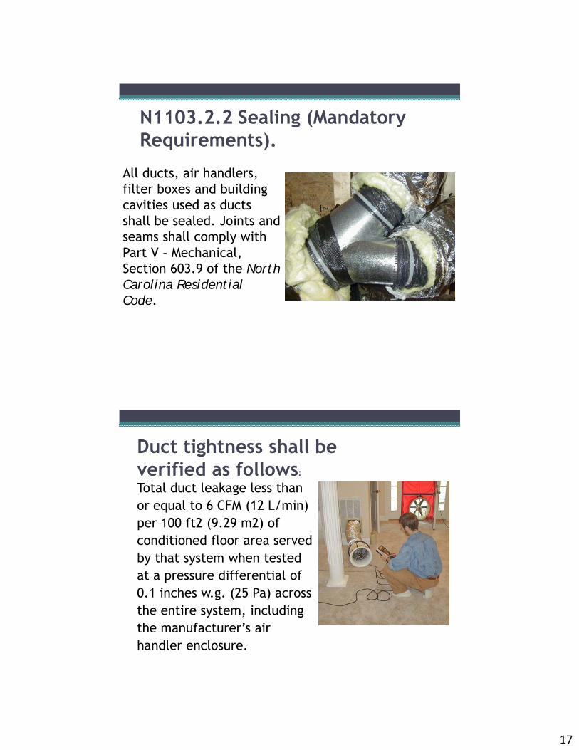
All ducts, air handlers, filter boxes and building cavities used as ducts shall be sealed. Joints and seams shall comply with Part V – Mechanical, Section 603.9 of the North Carolina Residential Code.
N1103.2.2 Sealing (Mandatory Requirements).
Total duct leakage less than or equal to 6 CFM (12 L/min) per 100 ft2 (9.29 m2) of conditioned floor area served by that system when tested at a pressure differential of 0.1 inches w.g. (25 Pa) across the entire system, including the manufacturer’s air handler enclosure.
Duct tightness shall be verified as follows:

18
1. Duct systems or portions thereof inside the building thermal envelope shall not be required to be leak tested.
2. Installation of a partial system as part of replacement, renovation or addition does not require a duct leakage test.
Exceptions to testing requirements:
N1104.1 Lighting equipment (Prescriptive).• A minimum of 75 percent of the
lamps in permanently installed lighting fixtures shall be high-efficacy lamps:
• CFL’s, T-8 or smaller fluorescents, or lamps with at least:
• 60 lumens/ W: lamps over 40 W,• 50 lumens/ W: lamps 15.1-40 W• 40 lumens/ W: 15 W or less

19
Lighting Efficacy
mondoarc.com – promotes LED Lighting
2012 NC Commercial Energy Code
Chapters Subjects
1–2 Administration and definitions
3 Climate zones and general materials requirements
4 Energy efficiency for residential buildings
5 Energy efficiency for commercial buildings
6 Referenced standards

20
NC Climate Zones: 3, 4, 5
Mel’s Diner Kurt’s Five & Dime
Spaces undergoing a change in occupancy that would result in an increase in demand for either fossil fuel or electrical energy shall comply with this code. Where the use in a space changes from one use in Table 505.5.2 to another use in Table 505.5.2, the installed lighting wattage shall comply with Section 505.5.
101.4.4 Change in occupancy or use

21
Change In Occupancy• Alterations to Existing Spaces• Applies to only portions of the systems being
altered• Applies if alteration increases energy use• Alterations must
meet the requirements applying to the altered component
• New systems in the alterations must comply
101.4.5 Change in space conditioning
Any non-conditioned space that is altered to become conditioned space shall be required to be brought into full compliance with this code.Exception: See 101.4.3, exception 2.
Where a building includes both residential and commercial occupancies, each occupancy shall be separately considered and meet the applicable provisions of Chapter 4 for residential and Chapter 5 for commercial.
101.4.6 Mixed occupancy

22
Mixed Occupancy Buildings (Section 101.4.6)
Different commercial occupancies▫ Each portion of the building
shall conform to the requirements of that occupancy
Office
Clothing Store
Barber Shop
Bakery Shoe Store
Mixed Occupancy Buildings (cont’d)
Hotel/motel and commercial occupancies▫ Treat as Different Commercial
OccupanciesMixed residential and commercial occupancies if < 3 stories▫ Treat the residential occupancy under
the applicable residential code▫ Treat the commercial occupancy under
the commercial codeIf > 3 stories▫ Treat all as commercial under the
commercial code
Restaurant
Apartments

23
101.5.2 Low energy buildings.The following buildings, or portions thereof, separated from the remainder of the building by building thermal envelope assemblies complying with this code shall be exempt from the building thermal envelope provisions of this code:
Those with a peak design rate of energy usage less than 3.4 Btu/h·ft2 (10.7 W/m2) or 1.0 watt/ft2 (10.7 W/m2) of floor area for space conditioning purposes.Those that do not contain conditioned space.
501.1 Scope. The requirements contained in this chapter are applicable to commercial buildings, or portions of commercial buildings. These commercial buildings shall either:• Option 1: Meet the requirements contained in
this chapter• Option 2: Comply with the mandatory provisions
of 2007 ASHRAE Standard 90.1 and exceed the minimum level of energy efficiency it prescribes by 20% following the procedure in ASHRAE/IESNA Standard 90.1, Appendix G.
• Option 3: Follow the performance path outlined in Section 507: Total Building Performance

24
Section 5 - Prescriptive Requirements, Building Envelope
VentilatedAttic
SemiheatedStorage
ConditionedSpace
VentilatedCrawlspace
Exterior Envelope
Non Thermal/ Air Barrier Envelope
UnconditionedSpace
The minimum thermal resistance (R-value) of the insulating material(s) installed in the wall cavity between the framing members and continuously on the walls shall be as specified in Table 502.2(1)
502.2.3 Above-grade walls.
The R-value of integral insulation installed in concrete masonry units (CMU) shall not be used determining compliance with Table 502.2(1). “

25
502.2.4 Below-grade walls.The minimum thermal resistance (R-value) of the insulating material installed in, or continuously on, the below-grade walls shall be as specified in Table 502.2(1), and shall extend to a depth of 10 feet (3048 mm) below the outside finished ground level, or to the level of the floor, whichever is less.
502.2.5 Floors over outdoor air or unconditioned space.The minimum thermal resistance (R-value) of the insulating material installed either between the floor framing or continuously on the floor assembly shall be as specified in Table 502.2(1), based on construction materials used in the floor assembly.
Insulation installed on a suspended ceiling with removable ceiling tiles shall not be considered part of the minimum thermal resistance of the roof insulation.

26
Basis for ASHRAE 2011 Insulation ValuesInputs to Standard 90.1 Criteria Optimization Program
Economics ScalarRatio 20.2 Fenestration Cost Year 2010
Construction Costs National 2010 Minimum (VLT/SHGC) Ratio 1.50Means Multiplier 1.00 Comm. HVAC Cooling Equipment Cost ($/Ton) 750
Energy Costs National 2010 HVAC Heating Equipment Cost ($/MBH) 23
Heating Cost ($/therm) 1.2201 Resid. HVAC Cooling Equipment Cost ($/Ton) 400Cooling Cost ($/kWh) 0.0939
0.0939Economic Life - Years 40Loan Interest Rate - % 7.0%
Heating Fuel Esc Rate - % 3.7%Cooling Fuel Esc Rate - % 3.7%
Federal Tax Rate - % 34.0%State Tax Rate - % 5.0%Discount Rate - % 7.0%
% Total 36.41% % Total 24.82%% Opaque 30.67% % Opaque 22.03%% Fenestration 38.30% % Fenestration 25.80%
Select Input Values
Fenestration Options
HVAC SizingNational 2010
Goto Reg Energy
Version: Jan 24, 2009 V1.0.068Version: Jan 24, 2009 V1.0.068
Energy Savings from Envelope (%Savings from 90.1-2004)
Energy Savings from Envelope (%Savings from IECC-2006)
Scalar Ratio Input ParametersCalculate
SR
Construction Type
1 Roof: Insulation Entirely Above Deck
3
Display LCC Construction Curve
Building TypeNonRes
Climate Zone
Display Construction-Climate
Curve
Zone 3 Results: Roof Deck Insulation
6. R-15 cont. insulation7. R-20 c.i.8. R-25 c.i.9. R-30 c.i.
Typical ASHRAE Lifecycle Cost Curve

27
ASHRAE Criteria Optimization Program
• Conducts Cost Benefit Analysis for Each Measure & Region
• Selects Cost Effective Efficiency Levels
Baseline Criteria Current Analysis ResultsStd 90.1-2007 SR = 20.2Non-Residential Cost Yr = National 2010 Green more stringent
EnerCos National 2010 Red less StringentConstCo National 2010
R-Value Difference
Opaque Element ZoneU, C, or F-Max R
U, C, or F-Max R (New - Old)
Roof Criteria: Insulation Entirely Above Deck 3 0.048 R-20.0 ci 0.039 R-25.0 ci 4.967Roof Criteria: Metal Building 3 0.055 R-13.0 + R-13.0 0.035 R-19.0 + R-11 LS 10.390Roof Criteria: Attic and Other 3 0.027 R-38.0 0.017 R-60.0 21.102Wall Criteria: Mass 3 0.123 R-7.6 ci 0.151 R-13.0 -1.529Wall Criteria: Metal Building 3 0.084 R-19.0 0.049 R-0.0 + R-19.5 ci 8.503Wall Criteria: Steel Framed 3 0.084 R-13.0 + R-3.8 ci 0.064 R-13.0 + R-7.5 ci 3.647Wall Criteria: Wood Framed and Other 3 0.089 R-13.0 0.051 R-13.0 + R-7.5 ci 8.295Wall Criteria: Below-Grade Walls 3 1.140 NR 0.119 R-7.5 ci 7.498Floor Criteria: Mass 3 0.107 R-6.3 ci 0.064 R-12.5 ci 6.279Floor Criteria: Steel Joist 3 0.052 R-19.0 0.038 R-30.0 7.294Floor Criteria: Wood Framed and Other 3 0.051 R-19.0 0.027 R-38.0 17.429Slab-on-Grade Floor Criteria (Unheated) 3 0.730 NR 0.540 R-10.0 for 24 in. 0.482Slab-on-Grade Floor Criteria (Heated) 3 0.900 R-10 for 24 in. 0.860 R-15.0 for 24 in. 0.052Opaque Door Criteria: Swinging 3 0.700 uninsulated 0.500 insulated 0.571Opaque Door Criteria: Non-Swinging 3 1.450 uninsulated 0.500 insulated 1.310Roof Criteria: Single Rafter Roof 3 0.055 R-19.0 0.052 R-21.0 1.236
Back to Inputs
Goto SkyLight
Goto Fen C it i
Steel Framing and Insulation

28
U-factors for Metal Stud WallsNominal Effective U-R-value R-value factor 1/2" EPS 1" XPS 2" XPS
(R-2.0) (R-5.0) (R-10.0)2 x 4 Metal Framing at 16 inches on Center (3.5 in cavity depth)
None (0.0) 0.352 0.207 0.128 0.078R-11 (5.5) 0.132 0.105 0.080 0.057R-13 (6.0) 0.124 0.100 0.077 0.055R-15 (6.4) 0.118 0.096 0.074 0.054
2 x 6 Metal Framing at 16 inches on Center (5.5 in cavity depth)
R-19 (7.1) 0.109 0.09 0.071 0.052R-21 (7.4) 0.106 0.087 0.069 0.051
2 x 6 Metal Framing at 24 inches on Center (5.5 in cavity depth)
R-19 (8.6) 0.094 0.079 0.064 0.048R-21 (9.0) 0.09 0.077 0.062 0.048
Continuous Insulated Sheathing
Source: ASHRAE 90.1 Standard – 2004.
Concrete Block Walls
• Concrete Masonry Units▫ Insulation-filled CMU used to
comply
▫ IECC 2006 and later: “The R-value of integral insulation installed in concrete masonry units (CMU) shall not be used in determining compliance with Table 502.2(1)”

29
TABLE 502.2(1) : OPAQUE ASSEMBLIES – WALLS
Climate Zone 3 4 5
All Other Group R All Other Group R All Other Group RWalls, Above Grade
Mass R-7.6 ci R-9.5 ci R-9.5 ci R-11.4 ci R-11.4 ci R-15 ciMetal buildingb
R-0+R-13 ci
R-0 + R-19 ci
R-0 + R-15.8 ci
R-0 + R-19 ci
R-0 + R-19 ci
R-0 + R-19 ci
Metal framed R-13 + 7.5 ci
R- 13 +R-7.5 ci
R-13 + R-10 ci
R-13 + R-12.5 ci
R-13 + R-12.5 ci
R- 13 + R-15 ci
Wood framed and other
R-13 + R-3.8 ci
R-19, R-13+ R-5, or R-15 +
R-3g
R-13 + R-7.5 ci
R-19, R-13+ R-5, or R-15 +
R-3g
R-13 + R-10 ci
R-19, R-13+ R-5, or R-15 +
R-3g
Walls, Below Grade
Below-grade wallc
R-7.5 ci R-7.5 ci R-7.5 ci R-10 ci R-7.5 ci R-10 ci
Group R = Residential 4 stories and above; ci = continuous insulation

30
Foam Sheathing Provides Thermal Break• Provides thermal break• Can serve as moisture
barrier and rain screen• Can also serve as
exterior air barrier if seams are sealed
Wall Construction – Foam on the Exterior

31
Wall Construction – Foam on the Exterior
Attachment of Cladding to Foam Plastic Sheathing

32

33
Sample Fastener Requirements for Cladding Attachment over Foam Plastic Sheathing
Metal Buildings
Insulate outside of the metal structure without compressing insulation if at all possible

34
TABLE 502.2(1) : BUILDING ENVELOPE REQUIREMENTS – OPAQUE ASSEMBLIES (ROOFS)
Climate Zone 3 4 5
All Other Group R All Other Group R All Other Group RRoofs
Insulation entirely above deck
R - 25 ci R-25 ci R - 30 ci R-30 ci R - 30 ci R-30 ci
Metal buildings (with R-5 thermal blocks)a,b
R-10 + R-19 FC
R-10 + R-19 FC
R-19 + R-11 Ls
R-19 + R-11 Ls
R-19 + R-11 Ls
R-19 + R-11 Ls
Attic and other - wood framing
R-38 R-38 R-42 R-42 R-42 R-42
Attic and other - steel framing
R-38 R-38 R-49 R-49 R-49 R-49
Foam Roof Decks: (Zone 3: R-25; Zone 4 & 5: R-30

35
Inspection is Critically Important!
• Insulation specification was R-30 foam on roof deck according to the plans (and HVAC design)
• The 2.5 inches found installed in the field would only provide about R-15
2.5”
TABLE 502.2(1) : OPAQUE ASSEMBLIES –FLOORS/ DOORS
Climate Zone 3 4 5
All Other Group R All Other Group R All Other Group RFloors
Mass R-12.5 ci R-12.5 ci R-14.6 ci R-16.7 ci R-14.6 ci R-16.7 ciJoist / Framing
R-30e R-30e R-38 R-38 R-38 R-38
Slab-on-Grade Floorsd
Unheated slabs
NR R-10 for 24 in.
R-15 for 24 in.
R-15 for 24 in.
R-15 for 24 in.
R-20 for 24 in.
Heated slabs R-15 for 24 in.
R-15 for 24 in.
R-20 for 24 in.
R-20 for 48 in.
R-20 for 48 in.
R-20 for 48 in.
Opaque Doors
Swinging U – 0.70 U – 0.50 U – 0.50 U – 0.50 U – 0.50 U – 0.50
Roll-up or sliding
U - 0.50 U - 0.50 U - 0.50 U - 0.50 U - 0.50 U - 0.50

36
TABLE 502.1.2BUILDING ENVELOPE REQUIREMENTS OPAQUE ELEMENT, MAXIMUM U-FACTORS
Climate Zone 3 4 5
All Other Group R All Other Group R All Other Group RRoofs
Insulation entirely above deck
U-0.039 U-0.039 U-0.032 U-0.032 U-0.032 U-0.032
Metal buildings (with R-5 thermal blocksa)
U-0.041 U-0.041 U-0.035 U-0.035 U-0.035 U-0.035
Attic and other U-0.027 U-0.041 U-0.021 U-0.021 U-0.021 U-0.021Walls, Above Grade
Mass U-0.123 U-0.104 U-0.104 U-0.090 U-0.090 U-0.060Metal building
U-0.072 U-0.050 U-0.060 U-0.050 U-0.050 U-0.050
Metal framed U-0.064 U-0.064 U-0.055 U-0.049 U-0.049 U-0.043
Wood framed and other
U-0.064 U-0.051 U-0.051 U-0.045 U-0.045 U-0.041
TABLE 502.1.2BUILDING ENVELOPE REQUIREMENTS OPAQUE ELEMENT, MAXIMUM U-FACTORS
Walls, Below GradeBelow-grade walla
C-0.119 C-0.119 C-0.119 C-0.092 C-0.119 C-0.092
FloorsMass U-0.064 U-0.064 U-0.057 U-0.051 U-0.057 U-0.051Joist / Framing
U-0.033 U-0.033 U-0.027 U-0.027 U-0.027 U-0.027
Slab-on-Grade FloorsUnheated slabs
F-0.730 F-0.540 F-0.520 F-0.520 F-0.520 F-0.510
Heated slabs
F-0.860 F-0.860 F-0.688 F-0.688 F-0.688 F-0.688

37
TABLE 502.2(2) (OTHER) OPAQUE ASSEMBLIESROOFS DESCRIPTIONR-10 + R-19FC
Filled cavity fiberglass insulation.A continuous vapor barrier is installed below the purlins and uninterrupted by framing members. Both layers of uncompressed, unfaced fiberglass insulation rest on top of the vapor barrier and are installed parallel, between the purlins. A minimum R-3.5 thermal spacer block is placed above the purlin/batt, and the roofdeck is secured to the purlins. Drawings of typical details are shown in Appendix 2.2.
R-19 + R11 Ls
Liner System with minimum R-3.5 thermal spacer block.
A continuous membrane is installed below the purlins and uninterrupted by framing members. Uncompressed, unfaced insulation rests on top of the membrane between the purlins. Drawings of typical details are shown in Appendix 2.2.
WALLS
R-0 + R-13 ciR-0 + R-19 ci
The second rated R-value is for continuous rigid insulation installed between the metal wall panel and steel framing, or on the interior of the steel framing. Drawings of typical details are shown in Appendix 2.2.
TABLE 502.3: FENESTRATION (30% maximum of above-grade wall)
CLIMATE ZONE 3 4 5
Framing materials other than metal with or without metal reinforcement or claddingU-Factor 0.32 0.32 0.30Metal framing with or without thermal breakCurtain Wall/StorefrontU-Factor
0.45 0.45 0.38
Entrance Door U-Factor 0.77 0.77 0.77All Other U-Factora 0.45 0.45 0.45SHGC-All Frame TypesSHGC: PF < 0.25 0.25 0.25 0.40SHGC: 0.25 ≤ PF < 0.5 0.33 0.33 NRSHGC: PF ≥ 0.5 0.40 0.40 NR
PF = Projection factor for window overhang; SHGC = Solar Heat Gain Coefficient

38
Windows - SHGC
Solar Heat Gain Coefficient• Requirements dependent
on projection factor (PF)• National Fenestration
Rating Council (NFRC) tested
• SHGC = SC x .87 where SC isthe Shading Coefficient, a former window shading term Projection Factor (PF)
NFRC Label

39
Windows – Typical U-FactorsAluminum frame w/o
thermal break
Aluminum frame with
thermal break
Wood or Vinyl Frame
Single Glass 1.3 1.07 n/aDouble Glass, ½" air space 0.81 0.62 0.48Double glass, low-e, (E*=0.2), ½" air space 0.7 0.52 0.39Double glass, low-e, (E*=0.1), ½" air space 0.67 0.49 0.37Double glass, low-e, (E*=0.2), ½" space with argon 0.64 0.46 0.34Triple glass, low-e, on two panes, ½" paces with argon
0.53 0.36 0.23
Quadruple glass, low-e (E=.01) on two panes, ¼" spaces with krypton
n/a n/a 0.22
*E is the emittance of the low-e coated surface.
Source: 1993 ASHRAE Handbook: Fundamentals, (Atlanta, GA:American Society of Heating, Refrigerating, and Air-Conditioning
Engineers, Incorporated, 1993).
Note: These are example of whole window U-factors of 3 ft x 5 ft windows. U-factors vary somewhat with window size. Ask the
dealer for the specific values for the window you are looking at.
Windows – Requirements• Maximum of 30% of vertical wall area or must use
Energy Modeling option• Use assembly U-value• All windows must meet or exceed

40
Skylights
TABLE 502.3BUILDING ENVELOPE REQUIREMENTS: SKYLIGHTS
CLIMATE ZONE 3 4 5
Skylights (3% maximum, 5% if using automatic daylighting controls)U-Factor 0.60 0.60 0.60SHGC 0.35 0.35 0.40
502.4 Air leakage control – maximum air leakage rates for windows and doors(Mandatory Requirements).
502.4.1 Window and door assemblies. The air leakage of window and sliding or swinging door assemblies that are part of the building envelope shall be determined in accordance with AAMA/WDMA/CSA 101/I.S.2/A440, or NFRC 400 by an accredited, independent laboratory, and labeled and certified.
502.4.2 Curtain wall, storefront glazing and commercial entrance doors. Curtain wall, storefront glazing and commercial-glazed swinging entrance doors and revolving doors shall be tested for air leakage at 1.57 pounds per square foot (psf) (75 Pa)
41
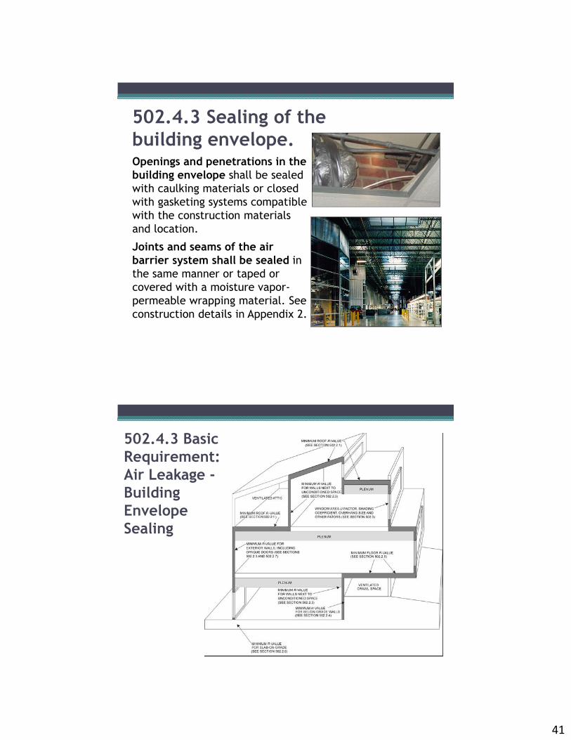
502.4.3 Sealing of the building envelope.Openings and penetrations in the building envelope shall be sealed with caulking materials or closed with gasketing systems compatible with the construction materials and location.
Joints and seams of the air barrier system shall be sealed in the same manner or taped or covered with a moisture vapor-permeable wrapping material. See construction details in Appendix 2.
502.4.3 Basic Requirement: Air Leakage -Building Envelope Sealing

42
Major Air Leakage Sites• Cavities above
suspended ceilings• Plenum return spaces
(Highly depressurized)• Ventilated walls• Equipment tunnels and
chases• Mechanical rooms and
mezzanines• Unconditioned adjacent space
(Storage, warehouse, plant, etc.)
• Exhaust and ventilation fans, plus wind and stack effect, are major driving forces
Limiting Air Leakage Pathways• Materials and connections must:
stop air flow withstand jobsite abuses withstand forces of wind and pressure
• Penetrations must be sealed plumbing, wiring, communications, ductwork, windows and doors
• Functional penetrations, such as air intakes for exhaust fans, must be dampered
• Vestibules (5 Stories or more, with exceptions)

43
502.4.5 Stair and elevator ventsShaft vents serving stairs and elevators integral to the building thermal envelope shall be equipped with not less than a Class I motorized, leakage-rated damper with a maximum leakage rate of 4 cfm per square foot (6.8 L/s · C m2) at 1.0 inch water gauge (w.g.) (125 Pa) when tested in accordance with AMCA 500D.
Exception: 1. Buildings without fire alarm systems.2. Stairway vents open to the exterior.
502.4.6 Loading dock weather-seals.
Cargo doors and loading dock doors shall be equipped with weather-seals to restrict infiltration when vehicles are parked in the doorway.

44
502.4.7 Vestibules.A door that separates conditioned space from the exterior shall be protected with an enclosed vestibule, with all doors opening into and out of the vestibule equipped with self-closing devices. Exceptions:1. Doors not intended to be used as a building entrance door, such as doors to mechanical or electrical equipment rooms.2. Doors opening directly from a sleeping unit or dwelling unit.3. Doors that open directly from a space less than 3,000 square feet (298 m2) in area.4. Revolving doors.5. Doors used primarily to facilitate vehicular movement or material handling and adjacent personnel doors.6. Building entrances in buildings that are less than four stories above grade and less than 10,000 ft2 in area.
502.4.8 Recessed lighting.Recessed luminaires installed in the building thermal envelope shall be IC-rated and labeled as meeting ASTM E 283 from the conditioned space to the ceiling cavity. Such recessed luminaires shall be sealed with a gasket or caulk between the housing and interior wall or ceiling covering.

45
SECTION 503BUILDING MECHANICAL SYSTEMS503.1 General. Mechanical systems and equipment serving the building heating, cooling or ventilating needs shall comply with Section 503.2 (referred to as the mandatory provisions) and either: 1. Section 503.3 (Simple systems), or2. Section 503.4 (Complex systems).
503.2.1 Calculation of heating and cooling loads.
Design loads shall be determined in accordance with the procedures described in the ASHRAE/ACCA Standard 183. Heating and cooling loads shall be adjusted to account for load reductions that are achieved when energy recovery systems are utilized in the HVAC system in accordance with the ASHRAE HVAC Systems and Equipment Handbook.

46
503.2.2 Equipment and system sizing.Heating and cooling equipment and systems capacity shall not exceed the loads calculated in accordance with Section 503.2.1, (within available equipment options. A single piece of equipment providing both heating and cooling must satisfy this provision for one function with the capacity for the other function as small as possible.)
Exceptions to Equipment Sizing:1. Required standby equipment and systemsprovided with controls and devices that allow such systems or equipment to operate automatically only when the primary equipment is not operating.2. Multiple units of the same equipment type with combined capacities exceeding the design load and provided with controls that have the capability to sequence the operation of each unit based on load.3. When the equipment selected is the smallest size within available options of the desired equipment line.

47
503.2.3 HVAC equipment performance requirements. Equipment shall meet the minimum efficiency requirements of
Tables 503.2.3(1), 503.2.3(2), 503.2.3(3), 503.2.3(4), 503.2.3(5), 503.2.3(6) and 503.2.3(7)
The efficiency shall be verified through certification under an approved certification program or by data furnished by the manufacturer.
Where multiple rating conditions or performance requirements are provided, the equipment shall satisfy all stated requirements.
Where components, such as indoor or outdoor coils, from different manufacturers are used, calculations and supporting data shall be furnished by the designer that demonstrates that the combined efficiency of the specified components meets the requirements herein. Exceptions specified in 503.2.3
Sample Table 503.2.3(1)EQUIPMENT TYPE SIZE CATEGORYe SUBCATEGORY OR
RATING CONDITIONMINIMUM
EFFICIENCYbTEST
PROCEDUREa
Air conditioners,Air cooled
< 65,000 Btu/hd (<= 5 nominal tons)
Split system 13.0 SEER AHRI 210/240Single package 13 SEER
≥ 65,000 Btuh/h and< 135,000 Btu/h
Split system andsingle package
11.2 EERc
≥ 135,000 Btu/h and< 240,000 Btu/h
Split system andsingle package
11.0 EERc AHRI 340/360
≥ 240,000 Btu/h and< 760,000 Btu/h
Split system andsingle package
10.0 EERc
9.7 IPLVg
≥ 760,000 Btu/h Split system andsingle package
9.7 EERc
9.4 IPLVc
Through-the-wall,Air cooled
< 30,000 Btu/hd Split system 12.0 SEER AHRI 210/240Single package 12.0 SEER
Air conditioners, Water
and evaporatively cooled
< 65,000 Btu/h Split system andsingle package
12.1 EER AHRI 210/240
≥ 65,000 Btu/h and< 135,000 Btu/h
Split system andsingle package
11.5 EERc
≥ 135,000 Btu/h and< 240,000 Btu/h
Split system andsingle package
11.0 EERc AHRI 340/360
≥ 240,000 Btu/h Split system andsingle package
11.5 EERc
48
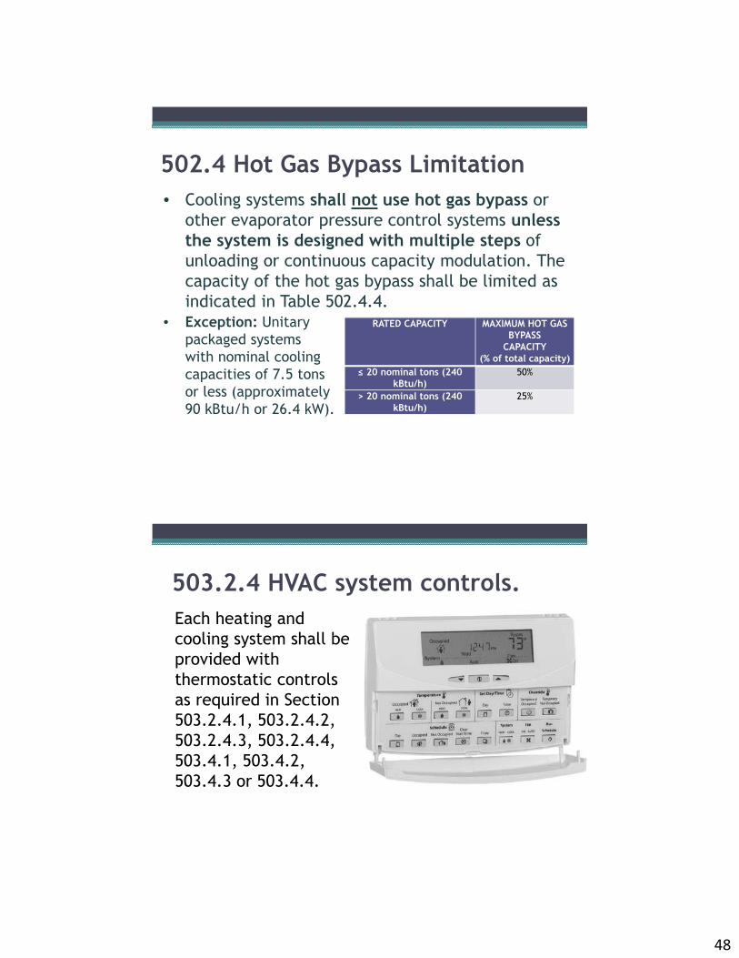
502.4 Hot Gas Bypass Limitation• Cooling systems shall not use hot gas bypass or
other evaporator pressure control systems unless the system is designed with multiple steps of unloading or continuous capacity modulation. The capacity of the hot gas bypass shall be limited as indicated in Table 502.4.4.
• Exception: Unitary packaged systems with nominal coolingcapacities of 7.5 tonsor less (approximately 90 kBtu/h or 26.4 kW).
RATED CAPACITY MAXIMUM HOT GAS BYPASS
CAPACITY(% of total capacity)
≤ 20 nominal tons (240 kBtu/h)
50%
> 20 nominal tons (240 kBtu/h)
25%
503.2.4 HVAC system controls.Each heating and cooling system shall be provided with thermostatic controls as required in Section 503.2.4.1, 503.2.4.2, 503.2.4.3, 503.2.4.4, 503.4.1, 503.4.2, 503.4.3 or 503.4.4.
49
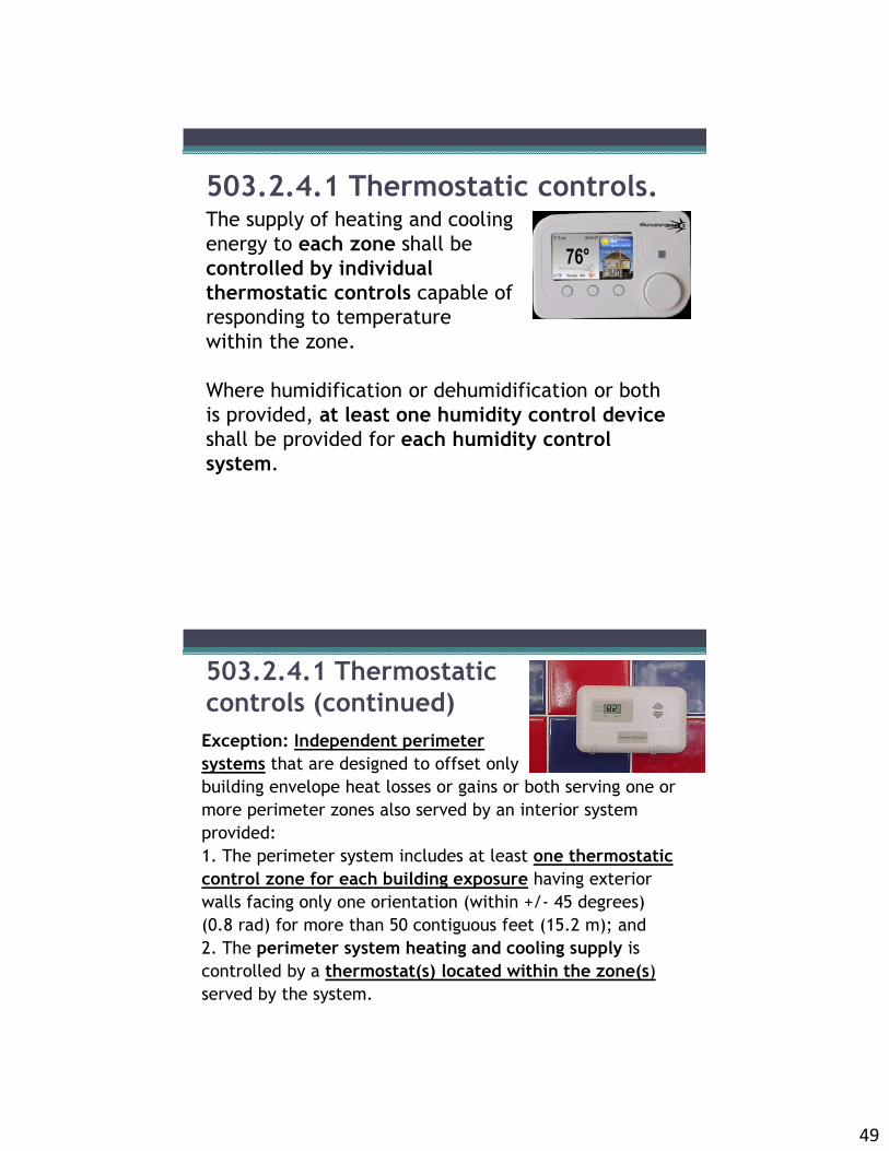
503.2.4.1 Thermostatic controls.The supply of heating and cooling energy to each zone shall be controlled by individual thermostatic controls capable of responding to temperature within the zone.
Where humidification or dehumidification or both is provided, at least one humidity control device shall be provided for each humidity control system.
503.2.4.1 Thermostatic controls (continued)Exception: Independent perimeter systems that are designed to offset only building envelope heat losses or gains or both serving one or more perimeter zones also served by an interior system provided:1. The perimeter system includes at least one thermostatic control zone for each building exposure having exterior walls facing only one orientation (within +/- 45 degrees) (0.8 rad) for more than 50 contiguous feet (15.2 m); and 2. The perimeter system heating and cooling supply is controlled by a thermostat(s) located within the zone(s)served by the system.

50
503.2.4.1.1 Heat pump supplementary heat.Heat pumps with supplementary electric resistance heat shall have controls that, except during defrost, prevent supplementary heat operation when the heat pump can meet the heating load.In systems with a cooling capacity of less than 65,000 Btuh, a heat strip outdoor temperature lockout shall be provided to prevent supplemental heat operation in response to the thermostat being changed to a warmer setting. The lockout shall be set no lower than 35F and no higher than 40oF.
503.2.4.2 Set point overlap restriction.Where used to control both heating and cooling, zone thermostatic controls shall provide a temperature range or dead-band of at least 5°F (2.8°C) within which the supply of heating and cooling energy to the zone is capable of being shut off or reduced to a minimum.
Exception: Thermostats requiring manual changeover between heating and cooling modes.

51
503.2.4.3 Off-hour controls.Each zone shall be provided with thermostatic setback controls that are controlled by either an automatic time clock or programmable control system.Exceptions:1. Zones that will be operated continuously.2. Zones with a full HVAC load demand not exceeding 6,800 Btu/h (2 kW) and having a readily accessible manual shutoff switch.3. HVAC systems serving hotel/ motel guestrooms or other residential units complying with Section 503.2.2 requirements.4. Packaged terminal air conditioners, packaged terminal heat pumps, and room air conditioner systems.
503.2.4.3.1 Thermostatic setback capabilities.
Thermostatic setback controls shall have the capability to set back or temporarily operate the system to maintain zone temperatures down to 55°F (13°C) or up to 85°F (29°C).

52
503.2.4.3.2 Automatic setback and shutdown capabilities.503.2.4.3.2 Automatic setback and shutdownCapabilities: Can start and stop the system for seven different daily schedules per week and retaining their programming and time setting during a loss of power for at least 10 hours.
Additionally, the controls shall have a manual override that allows temporary operation of the system for up to 2 hours; a manually operated timer capable of being adjusted to operate the system for up to 2 hours; or an occupancy sensor.
503.2.4.4 Shutoff damper controls.Outdoor air supply and exhaust ducts, fans or openings in the building thermal envelope shall be equipped with motorized dampers that will automatically shut when the systems or spaces served are not in use.
Exceptions:1. Gravity dampers shall be permitted in buildings less than three stories in height.2. Gravity dampers shall be permitted for outside air intake or exhaust airflows of 300 cfm(0.14m3/s) or less.

53
503.2.5 Ventilation.Ventilation, either natural or mechanical, shall be provided in accordance with Chapter 4 of the International Mechanical Code.
Where mechanical ventilation is provided, the system shall provide the capability to reduce the outdoor air supply to the minimum required by Chapter 4 of the International Mechanical for the design occupancy requirements.
503.2.5.1 Demand-controlled ventilation. Ventilation systems in buildings over 10,000 ft2 of conditioned area shall have demand controls.
In spaces larger than 500 ft2 with a maximum occupant load of 40 or more people per 1,000 ft2 of floor area, ventilation supply air flow shall be controlled by monitoring indoor air quality conditions, such as with CO2 sensors or thermostats. Demand controlled ventilation systems shall be capable of reducing outside supply air to at least 50% below design ventilation rates.
Note: Table 403.3 in Mechanical Code is source for occupancy loads.

54
503.2.5.1Cont.
Exceptions:1. Systems with energy recovery that provide a change in the enthalpy of the outdoor air supply of 50 percent or more of the difference between the outdoor air and return air at design conditions.2. Building spaces where the primary ventilation needs are for process loads, including laboratories and hospital.3. Individual units with less than 65,000 Btu/h of cooling capacity.
Objective of 503.2.5.1 Demand-controlled ventilation • Reduce unnecessary fan energy use when
ventilation is not needed due to low building occupancy
• Reduce humidity and thermal gain from outside when outside air is not needed for occupants
• Result – save $ thousands in energy costs and improve control over summer humidity gains

55
503.2.6 Energy recovery ventilation systems.Individual fan systems that have both a design supply air capacity of 5,000 cfm or greater and a minimum outside air supply of 70 percent or greater of the design supply air quantity shall have an energy recovery system that provides a change in the enthalpy of the outdoor air supply of 50 percent or more of the difference between the outdoor air and return air at design conditions.
503.2.6 outlines exceptions to the energy recovery requirement
503.2.6 Energy recovery ventilation exceptions
1. Where prohibited by the International Mechanical Code.2. Laboratory fume hood systems with at least one of the following:2.1. Variable-air-volume hood exhaust and room supply systems.2.2. Direct makeup (auxiliary) air supply equal to at least 75 percent of the exhaust rate, heated no warmer than 2°F below room setpoint, cooled to no cooler than 3°F above room setpoint, no humidification added, and no simultaneous heating and cooling used for dehumidification control.
3. Systems serving spaces that are not cooled and are heated to less than 60°F.4. Where more than 60 percent of the outdoor heating energy is provided from site-recovered or site solar energy.5. Heating systems in climates with less than 3,600 HDD.6. Cooling systems in climates with a 1-percent cooling design wet-bulb temperature less than 64°F.7. Systems requiring dehumidification that employ series-style energy recovery coils wrapped around the cooling coil.

56
503.2.7 Duct and plenuminsulation and sealing.Supply and return air ducts and plenums insulation minimums:
R-5 insulation in unconditioned spaces R-8 insulation outside the buildingWhen located within a building envelope assembly, the duct or plenum shall be separated from the building exterior or unconditioned or exempt spaces by a minimum of R-8 insulation.
Exceptions:1. When located within equipment.2. When the design delta T between the interior and exterior of the duct or plenum does not exceed 15°F.
Duct Sealing Requirements
Follow Section 603.9 of the International Mechanical Code▫ 503.2.7.1.1 Low-pressure duct systems: up to 2” w.g.▫ 503.2.7.1.2 Medium-pressure duct systems: 2 to 3” w.g.; ▫ 503.2.7.1.3 High-pressure duct systems: > 3” w.g.
pressure; requires testing

57
503.2.8 Piping insulation.All piping serving as part of a heating or cooling system shall be thermally insulated in accordance with Table 503.2.8.
FLUID NOMINAL PIPE DIAMETER≤ 1.5" 1.5"
Steam 1.5” 3”Hot water 1.5” 2”Chilled water, brine or refrigerant
1.5” 1.5”
Exceptions to requirement outlined in 503.2.8 (primarily for factory-installed equipment, lower delta T situations, refrigerant suction lines, special cases)Note: Minimum insulation thickness is based on a minimum k-value of 0.27 Btu-inch/ hr - sq ft - deg F
TABLE 503.2.8MINIMUM PIPE INSULATION(thickness in inches)
503.2.9 HVAC System Completion(prior to issuance of CO)
Exception: A temporary certificate of occupancy shall be allowed to be issued when requested prior to the completion of this section.
503.2.9.1 System balancing. All HVAC systems shall be balanced by contractor. Test and balance activities shall include as a minimum the following items:
503.2.9.1.1 Air systems balancing Each supply air outlet and zone terminal device shall be equipped with means for air balancing in accordance with the requirements of Chapter 6 of the North Carolina Mechanical Code. Discharge dampers are prohibited on constant volume fans and variable volume fans with motors 10 hp (7.5kW) and larger.
Exceptions: 1. Fan with fan motors of 1 hp or less.
503.2.9.1.2 Hydronic systems balancing

58
503.2.9 HVAC System Completion (cont.)503.2.9.1.2 Hydronic systems balancing
Individual hydronic heating and cooling coils shall be equipped with means for balancing and pressure testing connections. Hydronic systems shall be balanced in a manner to first minimize throttling losses, then the pump impeller shall be trimmed or pump speed shall be adjusted to meet design flow conditions. Each hydronic system shall have either the ability to measure pressure across the pump, or test ports at each side of each pump.
Exceptions:
1. Pumps with pump motors of 5 hp or less.
2. When throttling of an individual pump results in no greater than 5% of the nameplate horsepower draw above that required if the impeller were trimmed.
503.2.9 HVAC System Completion (cont.)503.2.9.1.2 Hydronic systems balancing
Individual hydronic heating and cooling coils shall be equipped with means for balancing and pressure test connections. Hydronic systems shall be balanced in a manner to first minimize throttling losses, then the pump impeller shall be trimmed or pump speed shall be adjusted to meet design flow conditions. Each hydronic system shall have either the ability to measure pressure across the pump, or test ports at each side of each pump.
Exceptions:
1. Pumps with pump motors of 5 hp or less.
2. When throttling of an individual pump results in no greater than 5% of the nameplate horsepower draw above that required if the impeller were trimmed.

59
503.2.9.2 Manuals (System Completion, cont.)An operating and maintenance manual shall be provided to the building owner by the contractor. The manual shall include:1. Submittal data stating equipment model number and capacity (input and output) and selected options.2. Manufacturer’s operation manuals and maintenance manuals for each piece of equipment requiring maintenance, except equipment not furnished as part of the project. Required routine maintenance actions shall be clearly identified. 3. Name and address of at least one service agency. 4. HVAC controls system maintenance and calibration information, including wiring diagrams, schematics, and control sequence descriptions. Desired or field-determined set points shall be permanently recorded on control drawings at control devices or, for digital control systems, in programming comments. 5. A complete narrative of how each system is intended to operate. 6. Names and addresses of designers of record, contractors, major subcontractors and equipment suppliers.
503.2.9.3 System installation statement (System Completion, cont.)A North Carolina licensed design professional shall prepare and sign the Statement of Compliance – HVAC System Installation (Appendix C). This statement shall be submitted to the code official and the facility owner.
Exception: 1. The HVAC contractor will be allowed to prepare the Statement of Compliance when a building permit is issued for a project without the seal of a licensed design professional as allowed by an exception under NC State Building Administrative Code and Policies: 204.3.5.

60
503.2.9.3 System installation statement (System Completion, cont.)503.2.9.3.1 Equipment Equipment installation and operation shall be verified, to the extent feasible, to be in accordance with approved plans and specifications. Verification shall include demonstration of operation of components, systems and system-to-system interfacing relationships.
503.2.9.3.2 Controls Controls installation and operation shall be verified, to the extent feasible, to be in accordance with approved plans and specifications. Verification shall include demonstration of operation of control devices, systems and system-to-system interfacing relationships. Control sequences shall be functionally verified, to the extent feasible, to demonstrate operation in accordance with the intent of the approved plans and specifications.
APPENDIX CStatement of Compliance – HVAC System Installation
Project Name:____________________________________________________Project Location:_________________________________________________In my professional opinion, the HVAC systems have been installed and are in substantial compliance with the intent of the approved project plans and specifications based on a site observation performed on _____________________ and upon review of the following:
Name:__________________________________________________________Signature:_______________________________________________________Date:___________________________________________________________Seal:___________________________________________________________
Yes No Not Required
Items Comments
Testing and balancing report
Operations and maintenance
manuals
HVAC Equipment
Control sequences

61
Table 503.2.10 Fan Power LimitationLIMIT CONSTANT VOLUME VARIABLE VOLUME
Option 1: Fan system motor nameplate
Allowable nameplate motor
hp ≤ CFMS *0.0011 + A hp ≤ CFMS *0.0015 + A
Option 2: Fan system bhp
Allowable fan system bhp
bhp ≤ CFMS *0.00094 + A bhp ≤ CFMS *0.0013 + A
where:CFMS = The maximum design supply airflow rate to conditioned spaces served by the system in
cubic feet per minute.
hp = The maximum combined motor nameplate horsepower.
Bhp = The maximum combined fan brake horsepower.A =Sum of [PD * CFMD / 4131],
PD = Each applicable pressure drop adjustment from Table 503.2.10.1(2) in. w.c.
Table 502.2.10.1 (2) Fan Power Limitation Pressure Drop Adjustment
DEVICE ADJUSTMENTCredits
Fully ducted return and/or exhaust air systems with capacity ≤ 20,000 cfm
0.5 in w.c.
Fully ducted return and/or exhaust air systems with capacity > 20,000 cfm
2.0 in w.c.
Return and/or exhaust air flow control devices 0.5 in w.c
Exhaust filters, scrubbers, or other exhausttreatment.
The pressure drop of device calculated at fan system design condition.
Particulate Filtration Credit: MERV 9 thru 12 0.5 in w.c.
Particulate Filtration Credit: MERV 13 thru 15 0.9 in w.c.

62
Table 502.2.10.1 (2) Fan Power Limitation Pressure Drop Adjustment (cont.)
DEVICE ADJUSTMENTCredits
Particulate Filtration Credit: MERV 16 andgreater and electronically enhanced filters
Pressure drop calculated at 2x clean filter pressure drop at fan system design condition.
Carbon and Other gas-phase air cleaners Clean filter pressure drop at fan system design condition.
Heat Recovery Device Pressure drop of device at fan system design condition.
Evaporative Humidifier/Cooler in series withanother cooling coil
Pressure drop of device at fan system design conditions
Sound Attenuation Section 0.15 in w.c.Deductions
Fume Hood Exhaust Exception(required if 503.2.10.1.1 Exception 3 is taken)
-1.0 in w.c.
Table 503.2.1 Fan Power Limitation (cont.)Exceptions:1. Hospital and laboratory systems that utilize flow control devices on exhaust and/or return to maintain space pressure relationships necessary for occupant health and safety or environmental control shall be permitted to use variable volume fan power limitation.2. Individual exhaust fans with motor nameplate horsepower of 1 hp or less.3. Fans exhausting air from fume hoods.

63
503.2.11 Heating outside a building.Systems installed to provide heat outside a building shall be radiant systems. Such heating systems shall be controlled by an occupancy sensing device or a timer switch, so that the system is automatically de-energized when no occupants are present.
503.3 Simple HVAC systems and equipment (Prescriptive). This section applies to buildings served by unitary or packaged HVAC equipment listed in Tables 503.2.3(1) through 503.2.3(5), each serving one zone and controlled by a single thermostat in the zone served.
503.3.1 Economizers.Supply air economizers shall be provided on each cooling system as shown in Table 503.3.1(1).Economizers shall be capable of providing 100-percent outdoor air, even if additional mechanical cooling is required to meet the cooling load of the building. Systems shall provide a means for pressure relief; the relief air outlet shall be located to avoid recirculation into the building.
CLIMATE ZONES ECONOMIZER REQUIREMENT
1A, 1B, 2A, 7, 8 No requirement2B, 3A, 3B, 3C, 4A, 4B,4C, 5A, 5B, 5C, 6A, 6B
Economizers on all cooling systems ≥ 65,000Btu/ha

64
503.4 Complex HVAC systems and equipment. (Prescriptive).This section applies to buildings served by HVAC equipment and systems not covered in Section 503.3.503.4.1 Economizers. Supply air economizers shall be provided on each cooling system according to Table 503.3.1(1). Economizers shall be capable of operating at 100 percent outside air, even if additional mechanical cooling is required to meet the cooling load of the building.Exceptions to requirement outlined in 503.4.1
Individual VAV fans with motors of 10 horsepower or greater shall be:1. Driven by a mechanical or electrical variable speed drive; or2. The fan motor shall have controls or devices that will result in fan motor demand of no more than 30 percent of their design wattage at 50 percent of design airflow when static pressure set point equals one-third of the total design static pressure
503.4.2 Variable air volume (VAV) fan control.

65
Other HVAC Provisions• 503.4.3 Hydronic System Controls▫ 503.4.3.1 Three-pipe system (prohibited)
▫ 503.4.3.2 Two-pipe changeover system (allow at least 15 degree deadband on outside temperatures; 4 hours of use in one mode; max 30 deg F difference at changeover point for heating and cooling supply temps)
▫ 503.4.3.3 Hydronic (water loop) heat pump systems 503.4.3.3.1 Temperature dead band (20 deg F between initiation
of heat addition and heat rejection) 503.4.3.3.2 Heat rejection (see next slides) 503.4.3.3.3 Two position valve (if total pump system power > 10
HP )▫ 503.4.3.4 Part load controls (includes reset/ reducing flow by
50% for systems > 300,000 Btuh) ▫ 503.4.3.5 Pump isolation (have capability to reduce flow when
chiller shuts down)
503.4.3.3.2 Heat rejectionHeat rejection equipment shall comply with Sections 503.4.3.3.2.1 and 503.4.3.3.2.2.Exception: Where it can be demonstrated that a heat pump system will be required to reject heat throughout the year.503.4.3.3.2.1 Climate Zones 3 and 4. For Climate Zones 3 and 4:1. If a closed-circuit cooling tower is used directly in the heat pump loop, either an automatic valve shall be installed to bypass all but a minimal flow of water around the tower, or lower leakage positive closure dampers shall be provided.2. If an open-circuit tower is used directly in the heat pump loop, an automatic valve shall be installed to bypass all heat pump water flow around the tower.3. If an open- or closed-circuit cooling tower is used in conjunction with a separate heat exchanger to isolate the cooling tower from the heat pump loop, then heat loss shall be controlled by shutting down the circulation pump on the cooling tower loop.

66
Other HVAC Provisions (cont.)• 503.4.4 Heat rejection equipment fan speed control (for
fan motors > 7.5 HP shall be able to operate at 2/3 speed or less and change fan speed to control fluid temp)
• 503.4.5 Requirements for complex mechanical systems serving multiple zones. Shall be VAV systems which are designed and capable of being controlled to reduce primary air supply to each zone before reheating, recooling or mixing takes place. 503.4.5.1 Single duct variable air volume (VAV) systems,
terminal devices. 503.4.5.2 Dual duct and mixing VAV systems, terminal
devices. 503.4.5.3 Single fan dual duct and mixing VAV systems,
economizers. 503.4.5.4 Supply-air temperature reset controls.
• 503.4.6 Heat recovery for service water heating
SECTION 504: SERVICE WATER HEATING (Mandatory Requirements)
504.1 General. 504.2 Service water-heating equipment performance efficiency. 504.3 Temperature controls. 504.4 Heat traps. 504.5 Pipe insulation. 504.6 Hot water system controls.
504.7 Pools and in-ground permanently installed spas (Mandatory).
504.7.1 Heaters. 504.7.2 Time switches.
Exceptions:1. 24-hour pump
operation.2. Solar- and waste-
heat-recovery pool heating systems.
504.7.3 Covers.

67
504.2 Service water-heating equipment performance efficiency.Water-heating equipment and hot water storage tanks shall meet the requirements of Table 504.2.
Service water-heating equipment shall be provided with controls to allow a set-point of 110°F (43°C) for equipment serving dwelling units and 90°F (32°C) for equipment serving other occupancies. The outlet temperature of lavatories in public facility rest rooms shall be limited to 110°F (43°C).
504.3 Temperature controls.
504.4 Heat traps.Water-heating equipment not supplied with integral heat traps and serving non-circulating systems shall be provided with heat traps on the supply and discharge piping associated with the equipment.

68
504.5 Pipe insulation.For automatic-circulating hot water systems, piping shall be insulated with 1 inch (25 mm) of insulation
TABLE 504.2: MINIMUM PERFORMANCE OF WATER-HEATING EQUIPMENT (Beginning of Chart Shown)
EQUIPMENT TYPE SIZE CATEGORY(input)
SUBCATEGORY ORRATING CONDITION
PERFORMANCEREQUIREDa, b
TESTPROCEDURE
Water heaters, Electric
≤ 12 kW Resistance 0.97 – 0.00132V, EF DOE 10 CFR Part 430
> 12 kW Resistance 1.73V + 155 SL, Btu/h ANSI Z21.10.3≤ 24 amps and≤ 250 volts
Heat pump 0.93 – 0.00132V, EF DOE 10 CFR Part 430
Storage water heaters,
Gas
≤ 75,000 Btu/h ≥ 20 gal 0.67 - 0.0019V, EF DOE 10 CFR Part 430
> 75,000 Btu/h and
≤ 155,000 Btu/h
< 4,000 Btu/h/gal 80% Et
(Q / 800+110√ V)SL,
Btu/h
ANSI Z21.10.3
> 155,000 Btu/h < 4,000 Btu/h/gal 80% Et
(Q / 800+110√ V)SL,
Btu/hInstantaneous
waterheaters, Gas
> 50,000 Btu/h and
< 200,000 Btu/hc
≥ 4,000 (Btu/h)/galand < 2 gal
0.62 - 0.0019V, EF DOE 10 CFR Part 430
≥ 200,000 Btu/h ≥ 4,000 Btu/h/gal and < 10 gal
80% Et ANSI Z21.10.3
≥ 200,000 Btu/h ≥ 4,000 Btu/h/gal and≥ 10 gal
80% Et
(Q / 800+110√ V)SL,
Btu/h
69
504.6 Hot water system controls. Automatic-circulating hot water system pumps or heat trace shall be arranged to be conveniently turned off automatically or manually when the hot water system is not in operation.
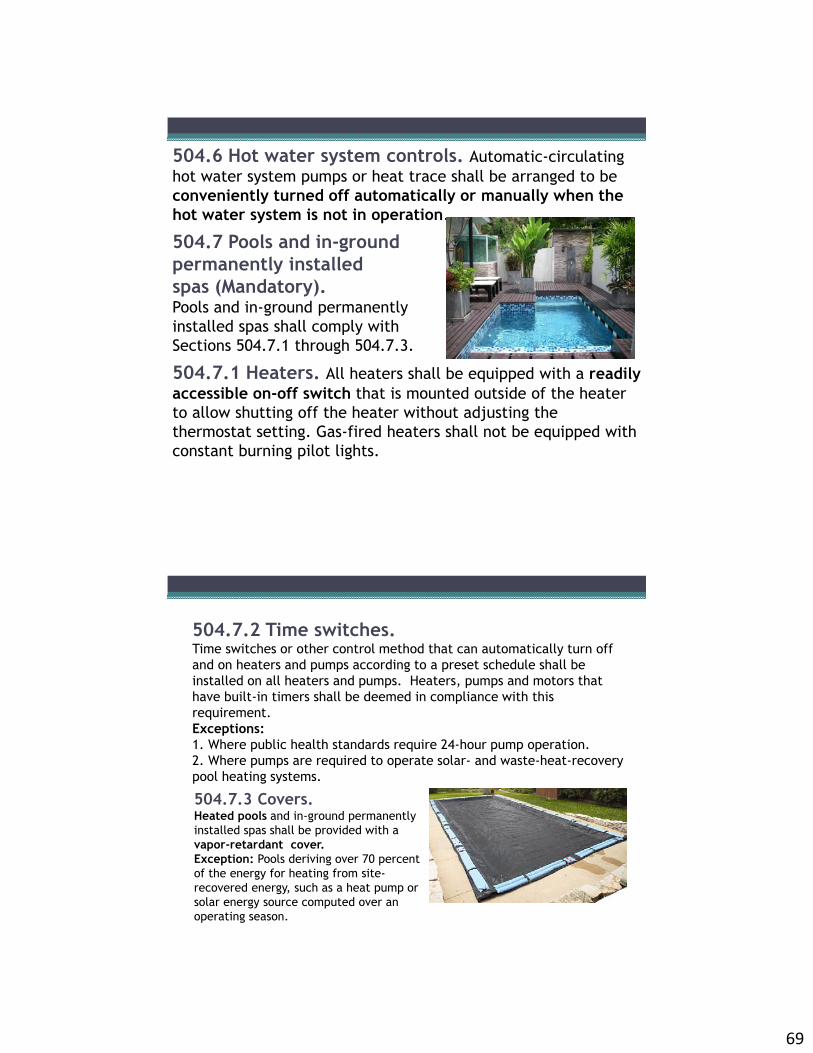
504.7 Pools and in-ground permanently installed spas (Mandatory). Pools and in-ground permanently installed spas shall comply with Sections 504.7.1 through 504.7.3.
504.7.1 Heaters. All heaters shall be equipped with a readily accessible on-off switch that is mounted outside of the heater to allow shutting off the heater without adjusting the thermostat setting. Gas-fired heaters shall not be equipped with constant burning pilot lights.
504.7.2 Time switches. Time switches or other control method that can automatically turn off and on heaters and pumps according to a preset schedule shall be installed on all heaters and pumps. Heaters, pumps and motors that have built-in timers shall be deemed in compliance with this requirement.Exceptions:1. Where public health standards require 24-hour pump operation.2. Where pumps are required to operate solar- and waste-heat-recovery pool heating systems.
504.7.3 Covers. Heated pools and in-ground permanently installed spas shall be provided with a vapor-retardant cover.Exception: Pools deriving over 70 percent of the energy for heating from site-recovered energy, such as a heat pump or solar energy source computed over an operating season.

70
SECTION 505 ELECTRICAL POWER AND LIGHTING SYSTEMS
505.1 General (Mandatory Requirements). This section covers lighting system controls, the connection of ballasts, the maximum lighting power for interior applications, and minimum acceptable lighting equipment for exterior applications
Exception: Lighting within dwelling units where 75 percent or more of the permanently installed interior light fixtures are fitted with high-efficacy lamps.
Energy-Efficient Lighting Sources

71
TABLE 505.5.2 ExampleINTERIOR LIGHTING POWER ALLOWANCES
LIGHTING POWER DENSITYWhole
BuildingSpace by
SpaceBuilding Area Typea (W/ft2)
Common Space TypesActive Storage 0.63Atrium - First Three Floors 0.63
Atrium - Each Additional Floor 0.16
Automotive Facility 0.91Bank / Office, Bank Activity Area 1.38
Classroom / Lecture / Training 1.25
Conference / Meeting / Multipurpose 1.29
Corridor / Transition 0.65Education Laboratory 1.28Electrical / Mechanical 0.95Food Preparation 0.99Lobby 0.60Locker Room 0.78Medical / Industrial Research Lab 1.62Parking Garage - Garage Area 0.21
Restroom 0.84Stairway 0.69Convention Center 1.05
505.2 Lighting controls (MandatoryRequirements).
Lighting systems shall be provided with controls as required in Sections 505.2.1, 505.2.2, 505.2.3, and 505.2.4.

72
505.2.1 Interior lighting controls.Each area enclosed by walls or floor-to-ceiling partitions shall have at least one manual control for the lighting serving that area. The required controls shall be located within the area served by the controls or be a remote switch that identifies the lights served and indicates their status.
Exceptions:1. Areas designated as security or emergency areas that must be continuously lighted.2. Lighting in stairways or corridorsthat are elements of the means of egress.
505.2.2.1 Light reduction controls.Each area that is required to have a manual control shall also allow the occupant to reduce the connected lighting load in a reasonably uniform illumination pattern by at least 50 percent. Methods (other approved are possible):1. Controlling all lamps or luminaires;2. Dual switching 3. Switching the middle lamp luminaires
independently of the outer lamps; or4. Switching each luminaire or each lamp.
Exceptions:1. Areas that have only one luminaire.2. Areas that are controlled by an occupant-sensing device.3. Corridors, storerooms, restrooms or public lobbies.4. Sleeping units (see Section 505.2.3).5. Spaces that use less than 0.6 watts per square foot (6.5 W/m2).

73
Bi-Level Switching
• Compliance Examples
•Example: Alternate Luminaires
•S•S
Bi-level with 4 lamp fixture

74
Bi-Level Switching
• Compliance Examples•Example: Alternate Lamps (a/b)
•S•S
•Example: Dimmer Control Option
•Dimmer Switch
•D
505.2.2.2.2 Occupancy sensors
• Classrooms• Conference/meeting rooms• Employee lunch and break
rooms• Private offices• Storage rooms over 100 s.f.• Computer rooms over 100
s.f.
All buildings shall have occupancy sensors in all of the following spaces:

75
505.2.2.2.3 Occupant overrideWhere an automatic time switch control device is installed to comply with Section 505.2.2.2.1, Item 1, it shall incorporate an override switching device that:1. Is readily accessible.2. Is located so that a person using the device can see the lights or the area controlled by that switch, or so that the area being lit is annunciated.3. Is manually operated.4. Allows the lighting to remain on for no more than 2 hours when an override is initiated.5. Controls an area not exceeding 5,000 square feet.Exceptions:1. In malls and arcades, auditoriums, single-tenant retail spaces, industrial facilities and arenas, where captive-key override is utilized, override time shall be permitted to exceed 2 hours.2. In malls and arcades, auditoriums, single-tenant retail spaces, industrial facilities and arenas, the area controlled shall not exceed 20,000 square feet.
505.2.2.2.4 Holiday scheduling.If an automatic time switch control device is installed in accordance with Section 505.2.2.2, Item 1, it shall incorporate an automatic holiday scheduling feature that turns off all loads for at least 24 hours, then resumes the normally scheduled operation.

76
505.2.3 Sleeping unit controls.
Sleeping units in hotels, motels, boarding houses or similar buildings shall have at least one master switch at the main entry door that controls all permanently wired luminaires and switched receptacles, except those in the bathroom(s). Suites shall have a control meeting these requirements at the entry to each room or at the primary entry to the suite.
505.2.4 Exterior lighting controls.• Lighting not designated for dusk-to-dawn operation shall be
controlled by either a combination of a photo-sensor and a time switch, or an astronomical time switch.
• Lighting designated for dusk-to-dawn operation shall be controlled by an astronomical time switch or photosensor.
• All time switches shall be capable of retaining programming and the time setting during loss of power for a period of at least 10 hours.

77
505.2.5.2 Hotel and Motel Guest Room Lightinghotel and motel guest rooms and guest suites shall have a master control device at the main room entry that controls all permanently installed luminaires and switched receptacles.
Supplemental task lighting, including permanently installed undershelf or undercabinet lighting, shall have a control device integral to the luminaires or be controlled by a wall-mounted control device provided the control device is readily accessible and located so that the occupant can see the controlled lighting.
505.2.5.3 Task Lighting
Guest Rooms
• Master switch required at entry
•Standard Room •Suite
•$
•$
•$•$
•$

78
505.2.6 Lighting controls functional performance testing requirements
For lighting controls which include daylight or occupant sensing automatic controls, automatic shut-off controls, occupancy sensors, or automatic time switches, the lighting control shall be tested to ensure that control devices, components, equipment, and systems are calibrated, adjusted and operate in accordance with approved plans and specifications.
505.3 Tandem wiring(Mandatory)The following luminaires located within the same area shall be tandem wired:1. Fluorescent luminaires equipped with one, three orodd-numbered lamp configurations, that are recess mounted within 10 feet (3048 mm) center-to-center of each other.2. Fluorescent luminaires equipped with one, three or any odd-numbered lamp configuration, that are pendant- or surface-mounted within 1 foot (305 mm) edge- to-edge of each other.

79
Tandem Wiring
Exceptions▫ Luminaires with electronic high-frequency ballasts▫ Luminaires not on same switch controls or not in the same
area
•Center to Center
505.4 Exit signs (Mandatory Requirements).
Internally illuminated exit signs shall not exceed 5 watts per side.

80
505.5 Interior lighting power requirements (Prescriptive).A building complies with this section if its total connected lighting power calculated under Section 505.5.1 is no greater than the interior lighting power calculated under Section 505.5.2.
The total connected interior lighting power (watts) shall be the sum of the watts of all interior lighting equipment as determined in accordance with Sections 505.5.1.1 through 505.5.1.4.
505.5.1 Total connected interior lighting power
Exceptions:1. The connected power associated with the following lighting equipment is not included in calculating total connected lighting power.1.1. Professional sports arena playing field lighting.1.2. Sleeping unit lighting in hotels, motels, boarding houses, etc.1.3. Emergency lighting automatically off during normal building operation.1.4. Lighting in spaces specifically designed for use by occupants with special lighting needs including the visually impaired visual impairment and other medical and age-related issues.1.5. Lighting in interior spaces that have been specifically designated as a registered interior historic landmark.1.6. Casino gaming areas.
2. Lighting equipment used for the following shall be exempt provided it is in addition to general lighting and is controlled by an independent control device:2.1. Task lighting for medical and dental purposes.2.2. Display lighting for exhibits in galleries, museums and monuments.

81
Exceptions (cont.) :3. Lighting for theatrical purposes, including performance, stage, film production and video production.4. Lighting for photographic processes.5. Lighting integral to equipment or instrumentation and is installed by the manufacturer.6. Task lighting for plant growth or maintenance.7. Advertising signage or directional signage.8. In restaurant buildings and areas, lighting for food warming or integral to food preparation equipment.9. Lighting equipment that is for sale.10. Lighting demonstration equipment in lighting education facilities. 11. Lighting approved because of safety or emergency considerations, inclusive of exit lights.
Sample Lighting Power Allowances
LIGHTING POWER DENSITYWhole Building Space by
SpaceBuilding Area Typea (W/ft2)
Common Space TypesActive Storage 0.63Atrium - First Three Floors 0.63
Atrium - Each Additional Floor 0.16
Automotive Facility 0.91Bank / Office, Bank Activity Area 1.38
Classroom / Lecture / Training 1.25
Conference / Meeting / Multipurpose 1.29
Corridor / Transition 0.65Education Laboratory 1.28Electrical / Mechanical 0.95Food Preparation 0.99Lobby 0.60Locker Room 0.78Medical / Industrial Research Laboratory
1.62
Parking Garage - Garage Area 0.21
Restroom 0.84Stairway 0.69Convention Center 1.05

82
1. Building area method:(a) Determine the appropriate building area type from Table 505.5.2 and the allowed lighting power density (watts per unit area) from the building area method column. For building area types not listed, selection of a reasonably equivalent type shall be permitted.(b) Determine the gross lighted floor area (square feet) of the building area type.(c) Multiply the gross lighted floor areas of the building area type(s) times the lighting power density.(d) The interior lighting power allowance for the building is the sum of the lighting power allowances of all building area types. Trade-offs among building area types are permitted provided that the total installed interior lighting power does not exceed the interior lighting power allowance.
2. Space-by-Space Method (a) Determine the appropriate building type from Table 505.5.2. For building types not listed, select a reasonable equivalent type.(b) For each space enclosed by partitions 80% or greater than ceiling height, determine the gross interior floor area by measuring to the center of the partition wall. Include the floor area of balconies or other projections. Retail spaces do not have to comply with the 80% partition height requirements.(c) Determine the interior lighting power allowance by using the columns designated space-by-space method in Table 505.5.2. Multiply the floor area(s) of the space(s) times the allowed lighting power density for the space type that most closely represents the proposed use of the space(s). The product is the lighting power allowance for the space(s). For space types not listed, selection of a reasonable equivalent category shall be permitted.(d) The interior lighting power allowance is the sum of lighting power allowances of all spaces. Trade-offs among spaces are permitted provided that the total installed interior lighting power does not exceed the interior lighting power allowance.

83
TABLE 505.6.2(1)EXTERIOR LIGHTING ZONES
LIGHTING ZONE DESCRIPTION
1 Developed areas of national parks, state parks, forest land, and rural areas
2 Areas predominantly consisting of residential zoning, neighborhood business districts, light industrial with limited nighttime use and residential mixed use areas
3 All other areas4 High-activity commercial districts in major
metropolitan areas as designated by the local land use planning authority
TABLE 505.6.2(2)INDIVIDUAL LIGHTING POWER ALLOWANCES FOR BUILDING EXTERIORS (Portion of Table)
Zone 3 Zone 4Base Site Allowance 750 W 1300 W
Tradable Surfaces (Lighting power densities for uncovered parking areas, building grounds, buildingentrances and exits,canopies and overhangs and outdoor sales areas may be traded.)
Uncovered Parking AreasParking areas anddrives
0.10 W/ft2 0.13 W/ft2
Building GroundsWalkways less than 10 feet wide
0.8 W/linear foot 1.0 W/linear foot
Walkways 10 feet wide or greaterPlaza areasSpecial Feature Areas
0.16 W/ft2 0.2 W/ft2
Stairways 1.0 W/ft2 1.0 W/ft2Pedestrian Tunnels 0.2 W/ft2 0.3 W/ft2
Building Entrances and ExitsMain entries 30 W/linear foot of
door width30 W/linear foot of door
widthOther doors 20 W/linear foot of
door width20 W/linear foot of door
widthEntry Canopies 0.4 W/ft2 0.4 W/ft2
Sales Canopies(free standing andattached)
0.8 W/ft2 1.0 W/ft2

84
Calculating Actual Connected Lighting Load
• Screw lamp holders – rated wattage of luminaire• Low-voltage lighting – wattage of transformer• Track lighting (above or 30 watts/ linear ft)• Connected Lighting Power calculation does not
include:▫ Specialized medical, dental, and research lighting▫ Professional sports arena lighting▫ Display lighting for exhibits (galleries, museums,
monuments)▫ Sleeping unit lighting▫ Emergency lighting
ExampleA 4,500 sq ft building has the following lighting:• 50 T-8 fixtures rated at 60 Watt each• 12 linear feet of track lighting• 10 screw-base lamps with 24-Watt compact
fluorescents, although the fixtures are rated at 75 Watts
• The Lighting Power Allowance for the building is 1.0 Watts/ sq ft, or 4,500 Watts for the building
Connected Power # Units Watts TotalT-8 fixtures 55 luminaires 60 3,300Track Lighting 12 lin ft 30 360Screw lamps (rated at 75 W) with 24 W CFL
10 luminaires 75 750
TOTAL 4,410

85
Exterior Lighting• Grounds – all luminaires over 100 watts must provide
a minimum of 160 lumens per watt (unless controlled by a motion sensor)
• Building – based on a calculation of Lighting Power Densities. Examples include:▫ Uncovered parking areas 0.15 W/ sq ft▫ Walkways less than 10 ft wide 1.0 watts/ lin ft▫ Walkways over 10 ft wide 0.2 watts/ sq ft▫ Stairways 1.0 watts/ sq ft▫ Main entries 30 watts/ lin ft of door▫ Other doors 20 watts/ lin ft of door▫ Canopies 1.25 watts/ sq ft▫ Building facades (per sq ft of wall) = 0.20 watts/ sq ft
SECTION 506ADDITIONAL PRESCRIPTIVE COMPLIANCE REQUIREMENTS
506.1 Requirements. Commercial buildings are required to comply with one of the following sections:
a. 506.2.1 More Efficient Mechanical Equipmentb. 506.2.2 Reduced Lighting Power Densityc. 506.2.3 Energy Recovery Ventilation Systemsd. 506.2.4 Higher Efficiency Service Water Heatinge. 506.2.5 On-Site Supply of Renewable Energyf. 506.2.6 Automatic Daylighting Control System
Gotta do one of them!
86
506.2.1 Efficient Mechanical Equipment This mechanical alternative compliance option is intended to allow the builder to meet the requirements of section 506 by choosing to install more efficient mechanical equipment.
506.2.2 Reduced Lighting Power Density -Whole Building Lighting Power Density (watts/SF) must comply with values 10% lower than those in Table 505.5.2. Compliance with this section is in addition to meeting the requirements of section 505.

87
506.2.3 Energy Recovery Ventilation SystemsBuildings using 500 cfm or more outdoor air shall have heat or energy recovery ventilation systems for at least 80% of ventilation air.
The recovery system shall provide a change in the enthalpy of the outdoor air supply of 50 percent or more of the difference between the outdoor air and return air at design conditions.
506.2.4 High Efficiency Service Water HeatingBuildings must be of the following types to use this compliance method:1. Hotels or Motels2. Hospitals3. Restaurants or buildings containing food preparation areas.4. Buildings with residential occupancies.5. Buildings with laundry facilities or other high process service water heating needs.6.Buildings showing a service hot water load of 8% or more of total building energy loads

88
The building service water heating system shall have one of the following:a. Instantaneous fuel-fired water heating systems for all fuel-fired water heating systems,b. Electric heat pump water heating systems,c. Water heating provided by geothermal heat pumps, ord. Solar water heating systems sized to provide at least 40% of hot water requirements.
506.2.5 On-site Supply of Renewable EnergyThe building or surrounding property shall incorporate an on-site renewable energy system that supplies 3% or more of total building energy loads. On-site power generation using nonrenewable sources does not meet this requirement.
1) is capable of providing at least 3% of the total energy load of the building, or2) provides on-site renewable energy generation with a nominal (peak) rating of 175 BTU's or 0.50 watts per square foot of building.

89
506.2.6 Automatic DaylightingControl System
A minimum of 30% of the total conditioned floor area shall be daylight zones with automatic controls that control lights in the daylit areas separately from the non-daylit areas.
Controls will automatically reduce lighting power in response to available daylight by either one of the following methods:
1. Continuous dimming using dimming ballasts and daylight-sensing automatic controls that are capable of reducing the power of general lighting in the day-lit zone 2. Stepped Dimming using multi-level switching and daylight-sensing controls that are capable of reducing lighting power automatically.

90
SECTION 507TOTAL BUILDING PERFORMANCE507.1 Scope.
This section establishes criteria for compliance using total building performance. The following systems and loads shall be included in determining the total building performance:heating systems, cooling systems, service water heating, fan systems, lighting power, receptacle loads and process loads.
507.3 Performance-based compliance.• Compliance based on total building performance requires
that a proposed building (proposed design) be shown to have an annual energy cost that is less than or equal to the annual energy cost of the standard reference design.
• Energy prices shall be taken from a source approved by the code official, such as the Department of Energy, Energy Information Administration’s State Energy Price and Expenditure Report.
• Code officials shall be permitted to require time-of-use pricing in energy cost calculations.
• Nondepletable energy collected off site shall be treated and priced the same as purchased energy.
• Energy from nondepletable energy sources collected on site shall be omitted from the annual energy cost of the proposed design.
Exception: Jurisdictions that require site energy (1 kWh = 3413 Btu) rather than energy cost as the metric of comparison.

91
507.4.1 Compliance report.Compliance software tools shall generate a report that documents that the proposed design has annual energy costs less than or equal to the annual energy costs of the standard reference design. The compliance documentation shall include the following information:• Address of the building; • An inspection checklist documenting the building component
characteristics of the proposed design as listed in Table 507.5.1(1) and a comparison of the estimated annual energy cost for standard reference design and proposed design;
• Name of individual completing the compliance report; and • Name and version of the compliance software tool.
507.6 Calculation software tools.Calculation procedures used to comply with this section shall be software tools capable of calculating the annual energy consumption of all building elements that differ between the standard reference design and the proposed design and shall include the following capabilities.1. Computer generation of the standard reference design using only the input for the proposed design. The calculation procedure shall not allow the user to directly modify the building component characteristics of the standard reference design.2. Building operation for a full calendar year (8760 hours). 3. Climate data for a full calendar year (8760 hours) and shall reflect approved coincident hourly data for temperature, solar radiation, humidity and wind speed for the building location.

92
507.6 Calculation software tools (cont.)
4. Ten or more thermal zones.5. Thermal mass effects.6. Hourly variations in occupancy, illumination, receptacle loads, thermostat settings, mechanical ventilation, HVAC equipment availability, service hot water usage and any process loads.7. Part-load performance curves for mechanical equipment.8. Capacity and efficiency correction curves for mechanical heating and cooling equipment.9. Printed code official inspection checklist listing each of the proposed design component characteristics from Table 507.5.1(1) determined by the analysis to provide compliance, along with their respective performance ratings (e.g., R-value, U-factor, SHGC, HSPF, AFUE, SEER, EF, etc.).
TABLE 507.5.1 SPECS FOR REFERENCE AND PROPOSED DESIGNS (SECTION 1)BUILDING COMPONENT
CHARACTERISTICSSTANDARD REFERENCE DESIGN PROPOSED DESIGN
Space use classification Same as proposed The space use classification shall be chosen in accordance with Table 505.5.2 for all areas of the building covered by this permit. Where the space use classification for a building is not known, the building shall be categorized as an office building.
Roofs Type: Insulation entirely above deckGross area: same as proposedU-factor: from Table 502.1.2Solar absorptance: 0.75Emittance: 0.90
As proposedAs proposedAs proposedAs proposedAs proposed
Walls, above-grade Type: Mass wall if proposed wall is mass; otherwisesteel-framed wallGross area: same as proposedU-factor: from Table 502.1.2Solar absorptance: 0.75Emittance: 0.90
As proposed
As proposedAs proposedAs proposedAs proposed
Walls, below-grade Type: Mass wallGross area: same as proposedU-Factor: from Table 502.1.2 with insulation layer on interior side of walls
As proposedAs proposedAs proposed
Floors, above-grade Type: joist/framed floorGross area: same as proposedU-factor: from Table 502.1.2
As proposedAs proposedAs proposed
Floors, slab-on-grade Type: UnheatedF-factor: from Table 502.1.2
As proposedAs proposed
Doors Type: SwingingArea: Same as proposedU-factor: from Table 502.2(1)
As proposedAs proposedAs proposed

93
Appendices of Building Details
502.4.3 Sealing of the building envelope -1. Air seal around fenestration frames

94
502.4.3 Sealing of the building envelope - 1. Air seal around fenestration frames
502.4.3 Sealing of the building envelope - 1. Air seal around door frames

95
502.4.3 Sealing of the building envelope -2. Air seal junctions between walls and foundations
502.4.3 Sealing of the building envelope -2. Air seal junctions between walls and foundations

96
502.4.3 Sealing of the building envelope -2. Air seal between walls and roof
502.4.3 Sealing of the building envelope -2. Air seal between walls and roof

97
502.4.3 Sealing of the building envelope -3. Air seal utility services through walls
502.4.3 Sealing of the building envelope - 3. Air sealing utility services through walls.

98
502.4.3 Sealing of the building envelope - 3. Air sealing utility services through walls and floors.
502.4.3 Sealing of the building envelope

99
502.4.3 Sealing of the building envelope
Table 502.2(2) Roofs.

100
Table 502.2(2) Roofs.
Table 502.2(2) Walls.

101
COMCheck
• 200 ft x 100 ft building = 20,000 sq ft• 15 ft walls = 9,000 sq ft (15 x perimeter (600))• R-25 ceiling• R-10 wall sheathing, no insulation in steel studs
(2x4, 16 inches on center)• 1,600 sq ft windows, 0.20 projection factor, U-
0.30, SHGC 0.25• 120 sq ft R-2.5 doors (U-0.40)• R-0 floor insulation
Comments/ Questions?