the army’s enhanced portable inductive artillery fuze...
TRANSCRIPT

ARDEC
Providing America Advanced Armaments for
Peace and War
THE ARMY’S ENHANCED PORTABLE INDUCTIVE ARTILLERY FUZE
SETTER (EPIAFS)PRESENTED TO THE NDIA FUZE SYMPOSIUM
APRIL 7, 2005
TOM WALKERCCommittedommitted TTo o EExcellencexcellence

• Sponsor: PM-Excalibur LTC ColeDPM: Chris GrassanoPOC: Mike Burke
• System: Tom Coradeschi• Platform Integration: Allison Marston• User: Ft Sill
POC: Steve Pearson• Software
– Andy Leshchyshyn– Craig Freed– Fred Taverni
• Mechanical– George Eckstein– Jim Hartranft– Spencer Hum– Jr. Knisley
• Electrical– Debbie Calomiris– Len Goodman– Hai Pham– Fred Oliver– Mary Labib – James Wiltz– Tom Walker– Jerry Frazier
EPIAFS TEAM
2
EPAIFS NDIA 2005.ppt
EPIAFSGun/Target LocationsGPS Data, Keys &
Precise TimePower
EPIAFS to SupportExcalibur
3
EPAIFS NDIA 2005.ppt
TrajectoryOptimized for
Range
Canards Steer Projectile
Canards Deploy GPS Acquisition and Track
GPS satellite
Target
Targeting info
FO
LW155 w/TADFire Control
AFATDS

PIKEPIAFS SYSTEM
• PLATFORM INTEGRATION KIT (PIK)– Single board
computer– Interface circuit
• SETTER and Cable
EPIAFS utilizesDAGR
SETTER
4
EPAIFS NDIA 2005.ppt
CABLE

5
EPAIFS NDIA 2005.ppt
EPIAFS Host: M777E1
Communication Location
Assembly (CLA)PIK goes here inside CLA
6
EPAIFS NDIA 2005.ppt
Setter
Host System Fire Control
Exc
alib
ur
Inductive coupling
Host System Communication
Location Assembly
Cable
Interface at rear of gun
Cable
Cable
Cable
DAGR Host System Navigation
Cable
Res
et
AA
Bat
tery
Battery
Host System Power
Key
Fill
Zero
Key
s
Mating Rear Connector
Platform Integration Kit
Rear Connector
AFATDS w/NABK
Radio Frequency connection or cable
as back-up
KeyItalics = items managed by PM Excalibur
= items common with Paladin
Host Ethernet
Port
Antenna
Power (4)Power (6)
Excalibur System Integrated into JLW155

PIK in CLA with ‘Rack-and-Panel’ Connector
7
EPAIFS NDIA 2005.ppt
Key Zero switchPIK Reset switch
Slide to help assemble PIK into place GPS
Antenna
Front hold-down screw
8
EPAIFS NDIA 2005.ppt
PIK FUNCTIONS• Formats and sends all
XM982 initialization data and TMP’s through Setter
• Passes Standard Fuze Data to Setter
• Interfaces with Host system
• Interfaces with Key Loader
• Stores black GPS crypto keys and Audit Trail
• Interfaces with SPORT or MSD
Rear connector
Interface card AA Battery cap
Zero swReset swKey fill
9
EPAIFS NDIA 2005.ppt
PIK BLOCK DIAGRAM
10pps
ZERO keys
AA Lithium
I/O
SBC
Serial A(RS-232)
Serial 1(RS-422)
Serial D(CMOS)
key audit trail
(flash)
Serial B(RS-232)
Ethernet
Serial C (CMOS)
Serial 2(CMOS)
Host FCSKey Fill
PIK INTERFACE CARD
Tamper sw
XM982 tx/rx data
Setter comm
Regulators
5v, 3.3v
Key micro
RS-422 drivers/receivers
System Reset
Reset
SPORT
DAGR (COM 3)
SETTER
Host Power
Rear Connector
Line Filter
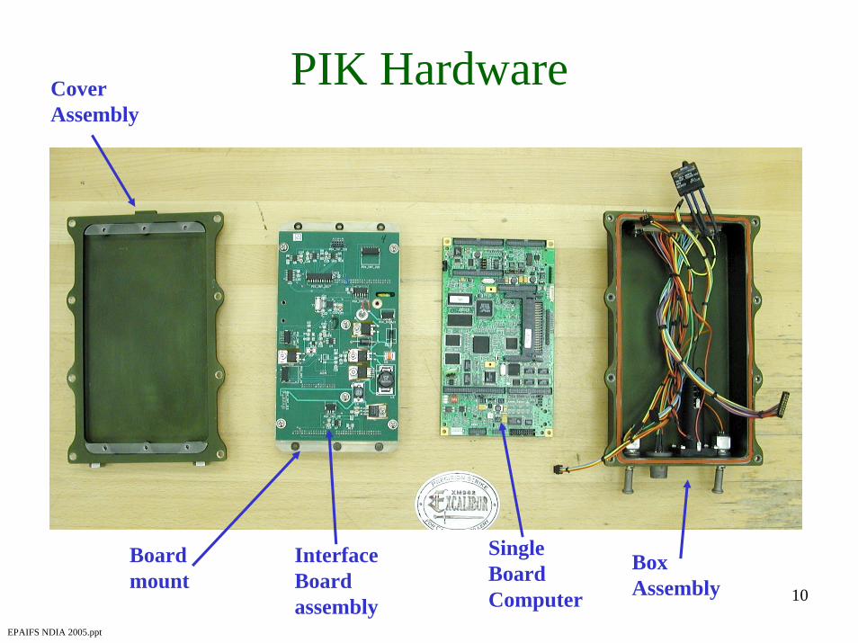
PIK HardwareCover Assembly
10
EPAIFS NDIA 2005.ppt
Box Assembly
Single Board Computer
Interface Board assembly
Board mount

PIK SINGLE BOARD COMPUTER• ADS “AGX” COTS• low power• 32M flash• 32M DRAM• 7 serial ports• Ethernet• 5”x7” size• LINUX OS
11
EPAIFS NDIA 2005.ppt
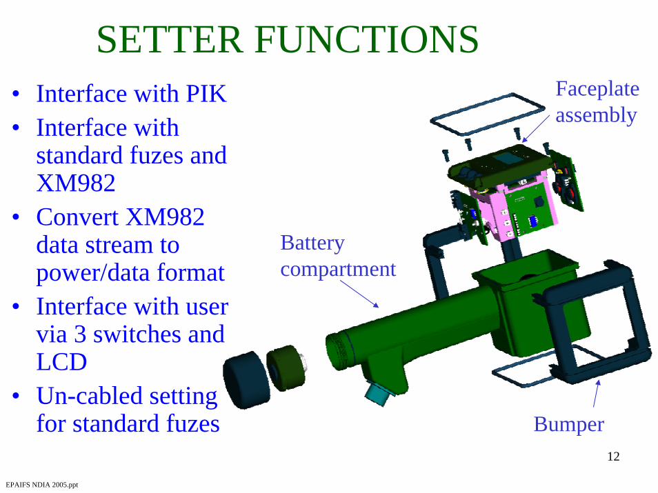
SETTER FUNCTIONS• Interface with PIK• Interface with
standard fuzes and XM982
• Convert XM982 data stream to power/data format
• Interface with user via 3 switches and LCD
• Un-cabled setting for standard fuzes Bumper
Faceplate assembly
Battery compartment
12
EPAIFS NDIA 2005.ppt
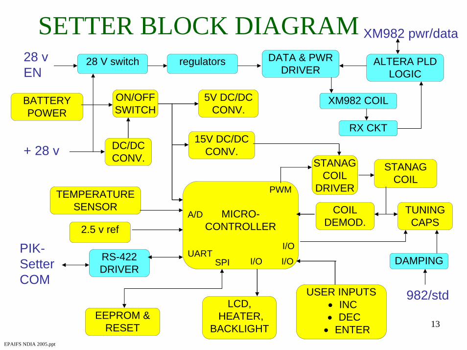
SETTER BLOCK DIAGRAM
13
EPAIFS NDIA 2005.ppt
DC/DCCONV.
15V DC/DCCONV.
BATTERYPOWER
5V DC/DCCONV.
EEPROM & RESET
MICRO-CONTROLLER
RS-422DRIVER
USER INPUTS• INC• DEC• ENTER
LCD,HEATER,
BACKLIGHT
STANAG COIL
DRIVER
COILDEMOD.
STANAGCOIL
TEMPERATURESENSOR
ON/OFF SWITCH
PWM
A/D
SPIUART
2.5 v ref
TUNING CAPS
I/O
I/OPIK-Setter COM
XM982 pwr/data
+ 28 v
DATA & PWR DRIVER
XM982 COIL
RX CKT
ALTERA PLD LOGIC
DAMPINGI/O
28 V switch28 v EN
regulators
982/std
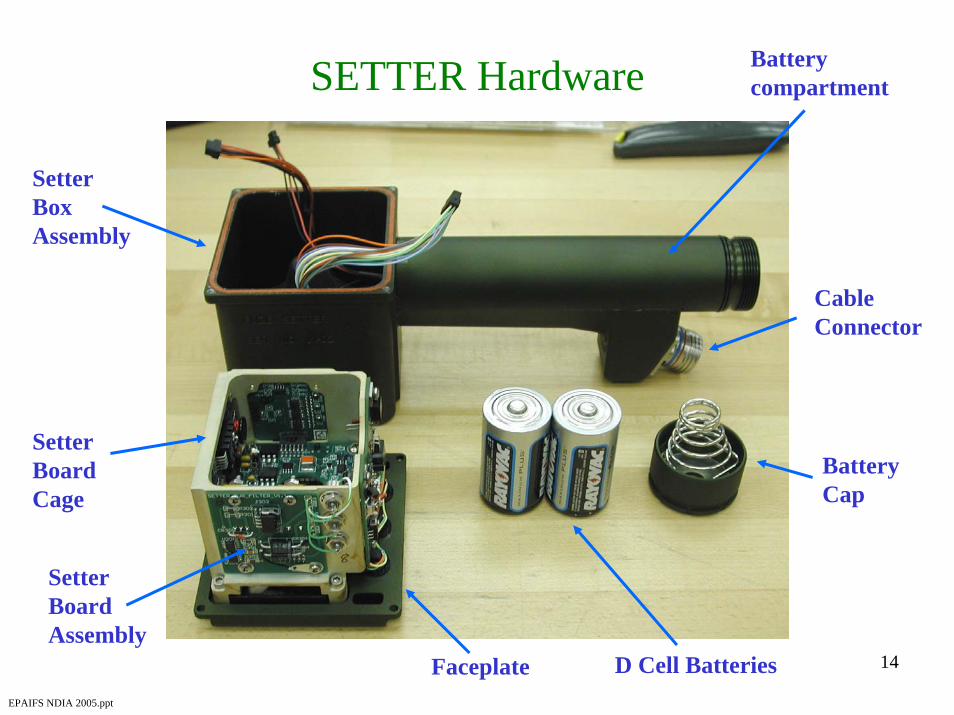
Battery compartmentSETTER Hardware
14
EPAIFS NDIA 2005.ppt
Setter Box Assembly
Setter Board Assembly
Cable Connector
Battery Cap
Setter Board Cage
D Cell BatteriesFaceplate

SETTER MODES
15
EPAIFS NDIA 2005.ppt
• Uncabled– Acts just like original PIAFS– Standard Fuze capable
• Cabled Manual– Same functionality as
Uncabled– Receives power externally
• Cabled Remote– Receives commands from
PIK– Standard and GPS Fuze
capable

16
EPAIFS NDIA 2005.ppt

EPIAFS Software Status• PIK SBC
– Written in C++– 23,500 lines of code– Field upgrade feature for PIK demonstrated – Transition from MPE-S to DAGR completed– Software approx 95% complete
• Still need to implement additional diagnostic capabilities
• PIK Key Micro– Code written in C– Application completed
• SETTER– Written in C– 11,700 lines of code– Software approx 95% complete
• Currently working on capability to field upgrade17
EPAIFS NDIA 2005.ppt

EPIAFS POWER BUDGET
• PIK– SBC: 2 watts– Interface board: 1 watt
• SETTER– Standby mode: 1/4 watt– Set Std fuzes: 1 watt for 3 sec– Cold temp: + 4 watts (LCD heater)– Set XM982: + 90 watts for 10 sec
18
EPAIFS NDIA 2005.ppt

ACCOMPLISHMENTS
19
EPAIFS NDIA 2005.ppt
• EPIAFS SRR - June 2003 • EPIAFS brass-board complete - Nov 2003• Brass-board inductive set GNU 1.0 - Dec 2003• Convert EPIAFS design to utilize DAGR - Jan 2004• EPIAFS PDR - Feb 2004• EPIAFS Prototype hardware build begins - June 2004• Modify coil driver for 606 ns data waveform - Sept 2004• Set “digital only” GNU 2.0 - Sept 04• EPIAFS Prototype inductive set GNU 1.0 - Nov 2004• GNU 2.0 (data MSB first) pass digital-fail inductive - Dec 2004• Setter Prototype LCD delivered - Dec 2004• Receive GNU 2.0 (data LSB first) - Jan 2005• EPIAFS Prototype inductive set GNU 2.0 - Feb 2005

PLANS
20
EPAIFS NDIA 2005.ppt
• Complete EPIAFS Prototype Build• Test EPIAFS with JLW-155 DAGR
and Talin• Substitute H-Drive Coil Circuit• Assist EPIAFS integration in JLW-155• Environmental Test EPIAFS• Update EPIAFS Design• Fabricate EPIAFS Qualification Units• Support JLW FQT