the art of network architecture -...
TRANSCRIPT


The Art of Network Architecture
Russ White, CCIE No. 2635
Denise Donohue, CCIE No. 9566
Cisco Press
800 East 96th Street
Indianapolis, Indiana 46240 USA

ii The Art of Network Architecture
The Art of Network Architecture
Russ White, CCIE No. 2635 Denise Donohue, CCIE No. 9566
Copyright© 2014 Cisco Systems, Inc.
Published by:Cisco Press800 East 96th StreetIndianapolis, IN 46240 USA
All rights reserved. No part of this book may be reproduced or transmitted in any form or by any means, electronic or mechanical, including photocopying, recording, or by any information stor-age and retrieval system, without written permission from the publisher, except for the inclusion of brief quotations in a review.
Printed in the United States of America
First Printing April 2014
Library of Congress Control Number: 2014932356
ISBN-13: 978-1-58714-375-5
ISBN-10: 1-58714-375-5
Warning and Disclaimer
This book is designed to provide information about the architecture aspects of network design. Every effort has been made to make this book as complete and as accurate as possible, but no war-ranty or fitness is implied.
The information is provided on an “as is” basis. The authors, Cisco Press, and Cisco Systems, Inc. shall have neither liability nor responsibility to any person or entity with respect to any loss or dam-ages arising from the information contained in this book or from the use of the discs or programs that may accompany it.
The opinions expressed in this book belong to the authors and are not necessarily those of Cisco Systems, Inc.
Trademark Acknowledgments
All terms mentioned in this book that are known to be trademarks or service marks have been appropriately capitalized. Cisco Press or Cisco Systems, Inc., cannot attest to the accuracy of this information. Use of a term in this book should not be regarded as affecting the validity of any trademark or service mark.

Special Sales
For information about buying this title in bulk quantities, or for special sales opportunities (which may include electronic versions; custom cover designs; and content particular to your business, training goals, marketing focus, or branding interests), please contact our corporate sales depart-ment at [email protected] or (800) 382-3419.
For government sales inquiries, please contact [email protected] .
For questions about sales outside the U.S., please contact [email protected] .
Feedback Information
At Cisco Press, our goal is to create in-depth technical books of the highest quality and value. Each book is crafted with care and precision, undergoing rigorous development that involves the unique expertise of members from the professional technical community.
Readers’ feedback is a natural continuation of this process. If you have any comments regarding how we could improve the quality of this book, or otherwise alter it to better suit your needs, you can contact us through email at [email protected] . Please make sure to include the book title and ISBN in your message.
We greatly appreciate your assistance.
Publisher: Paul Boger
Associate Publisher: Dave Dusthimer
Business Operation Manager, Cisco Press: Jan Cornelssen
Executive Editor: Brett Bartow
Managing Editor: Sandra Schroeder
Senior Development Editor: Christopher Cleveland
Senior Project Editor: Tonya Simpson
Copy Editor: Barbara Hacha
Technical Editors: Mark Cloud, Peter Welcher
Editorial Assistant: Vanessa Evans
Book Designer: Gary Adair
Cover Designer: Mark Shirar
Composition: Mary Sudul
Indexer: Erika Millen
Proofreader: Debbie Williams
iii

iv The Art of Network Architecture
About the Authors
Russ White , CCIE No. 2635, is a principal engineer in the IPOS team at Ericsson. He has worked in routing protocols and routed network design for the past 15 years. Russ has spoken at Cisco Live, Interop, LACNOG, and other global industry venues. He is actively involved in the IETF and the ISOC, has co-authored more than 30 software pat-ents in the area of network protocols, and has co-authored nine books in the area of net-work protocols, design, and architecture. He holds a Master of Information Technology in Network Design and Architecture from Capella University and a Master of Christian Ministry in Christian literature from Shepherds Theological Seminary.
Denise Donohue , CCIE No. 9566 (Routing and Switching), is a senior solutions architect with Chesapeake NetCraftsmen. Denise has worked with computer systems since the mid-1990s, focusing on network design since 2004. During that time she has designed for a wide range of networks, private and public, of all sizes, across most industries. Denise has also authored or co-authored many Cisco Press books covering data and voice networking technologies and spoken at Cisco Live and other industry events.

v
About the Technical Reviewers
Mark Cloud is a senior network engineer for The Walt Disney Company. As a member of the Enterprise Engineering Group, Mark carries broad responsibilities for the Disney Global Network with focus on the Core WAN, the routing plane, and address space management. Mark also has architectural oversight over DNS and DHCP services. In his long tenure at Disney and former subsidiary Vista-United Telecommunications, Mark has helped build and support everything from two-wire teletype feeds, multipoint ana-log data circuits, carrier transmission gear, early generation bridges and multiprotocol routers, to the current high-performance IP routing technologies linked by carrier MPLS and multi-gigabit WAN technologies that are in wide deployment today. Mark holds an Associate of Arts in Music from Polk Community College and a Bachelor of Science in Computer Information Services from Florida Southern College.
Dr. Peter J. Welcher is a principal consultant heading up the data center practice for Chesapeake NetCraftsmen, a Cisco Gold partner focused on providing high-end net-work, unified communications, and data-center consulting services. Pete is CCIE R&S No. 1773, has CCIP certification, and is a Cisco Champion. Over the years Pete has con-sulted on network architecture and design with many organizations, both large and small. He continues doing network architecture, design, and migration planning, both pre- and post-sales, as well as network assessments and other consulting tasks. He had a major role in developing version 2.0 of the Cisco courses for the CCDA and CCDP certifications and did tech review for the 2.1 Cisco Press book by John Tiso. Pete leads and coor-dinates a team doing infrastructure and data center consulting. Pete has taught Nexus classes via FireFlyEducate. He has presented on various topics at U.S. Cisco Live events since about 2005, and previously taught a number of the Cisco R&S courses. Pete blogs and tweets and has technically reviewed a number of Cisco Press books.

vi The Art of Network Architecture
Dedications
Russ White: I would like to dedicate this book to my beautiful wife, my two beauti-ful daughters, to Dr. Doug Bookman, and the folks at Shepherds Theological Seminary. Finally, to God, who provides me with the energy and skills to write; may I use the skills He has given with wisdom and to His glory.
Denise Donohue: This book is dedicated to my husband, who carries on without me when I’m writing, to my dogs, Buddy and Raleigh, who keep me company during the long hours at the computer, and to Jesus Christ, who is the solid rock in this constantly changing sea.

vii
Acknowledgments
Russ White: To Alvaro Retana, Don Slice, James Ng, Denise Fishburne, Danny McPherson, Donnie Savage, and all those I’ve worked with over the years at Cisco, Verisign, VCE, and Ericsson—thanks for taking the time and trouble to help me learn the many different aspects of network design and architecture. Without the help and guidance of mentors and sounding boards, I wouldn’t have a clue about how to design a network.
To my children—thanks for the insanity I’ve inherited. A little insanity is useful when dealing with something as strange as network architecture.
To Denise Donohue—thanks for sticking with this project. Books are always a bigger project than they seem at the beginning and a smaller project than they seem at the end.
To Brett Bartow, Chris Cleveland, and the crew at Pearson—thanks for, once again, giving me an opportunity to take what I know, add more to it, and produce something that will, I hope, influence and build the world of network engineering for years to come. Your trust and work is always appreciated.
To Pete Welcher, Mark Cloud, and all the “unofficial” reviewers—thanks for putting the time and effort into reading this book and thinking about where things didn’t make sense, where they do make sense, and what needed to be done to make it better. It’s always a pleasure to work with each and every one of you.
Denise Donohue: To Brett Bartow, Chris Cleveland, and the staff at Pearson—you have been more than patient as we worked to fit in authoring, day jobs, and life. I appreciate it, and want to thank you.
To Russ—Thanks for the opportunity to work on this book. It has indeed been a journey.
To the reviewers—Your work has been crucial to creating an understandable and useful book.
To the people at all the networks I’ve worked with over the years—I’ve tried to distill the lessons learned (good and bad), the processes and rationales behind design decisions, and the results of our labors into something that will help others going through that same process. Any examples that sound familiar to you are strictly a coincidence, honest!

viii The Art of Network Architecture
Contents at a Glance
Introduction xx
Part I Framing the Problem
Chapter 1 Business and Technology 1
Part II Business-Driven Design
Chapter 2 Designing for Change 11
Chapter 3 Improving Business Operations 19
Part III Tools of the Trade
Chapter 4 Models 35
Chapter 5 Underlying Support 57
Chapter 6 Principles of Modularity 67
Chapter 7 Applying Modularity 83
Chapter 8 Weathering Storms 97
Chapter 9 Securing the Premises 117
Chapter 10 Measure Twice 133
Part IV Choosing Materials
Chapter 11 The Floor Plan 147
Chapter 12 Building the Second Floor 171
Chapter 13 Routing Choices 193
Chapter 14 Considering Complexity 213
Part V Current and Future Trends
Chapter 15 Network in Motion 227
Chapter 16 On Psychologists, Unicorns, and Clouds 251
Chapter 17 Software-Defined Networks 265
Chapter 18 Data Center Design 287
Index 303

ix
Contents
Introduction xx
Part I Framing the Problem
Chapter 1 Business and Technology 1
Business Drives Technology 2
The Business Environment 2
The Big Picture 3
The Competition 4
The Business Side of the Network 5
Technologies and Applications 5
Network Evaluation 6
The Network’s Customers 6
Internal Users 7
External Users 8
Guest Users 9
Technology Drives Business 9
Part II Business-Driven Design
Chapter 2 Designing for Change 11
Organic Growth and Decline 12
Mergers, Acquisitions, and Divestments 14
Centralizing Versus Decentralizing 15
Chapter 3 Improving Business Operations 19
Workflow 19
Matching Data Flow and Network Design 20
Person-to-Person Communication 21
Person-to-Machine Communication 21
Machine-to-Machine Communication 22
Bringing It All Together 23
BYOD 24
BYOD Options 24
BYOD Design Considerations 27
BYOD Policy 28

x The Art of Network Architecture
Business Continuity 29
Business Continuity Versus Disaster Recovery 29
Business Continuity Planning 30
Business Continuity Design Considerations 31
Summary 33
Part III Tools of the Trade
Chapter 4 Models 35
The Seven-Layer Model 36
Problems with the Seven-Layer Model 38
The Four-Layer Model 38
Iterative Layering Model 39
Connection-Oriented and Connectionless 41
A Hybrid Model 42
The Control Plane 43
What Am I Trying to Reach? 43
Where Is It? 44
How Do I Get There? 45
Other Network Metadata 46
Control Plane Relationships 46
Routing 46
Quality of Service 48
Network Measurement and Management 49
Interaction Between Control Planes 49
Reactive and Proactive 51
The Waterfall Model 53
Places in the Network 54
Summary 56
Chapter 5 Underlying Support 57
Questions You Should Ask 57
What Happens When the Link Fails? 57
What Types of Virtualization Can Be Run Over This Link? 58
How Does the Link Support Quality of Service? 59
Marking Packets 59
Queues and Rate Limiters 59
Speeds and Feeds Versus Quality of Service 60

xi
Spanning Tree 61
TRILL 62
TRILL Operation 62
TRILL in the Design Landscape 64
TRILL and the Fabrics 65
Final Thoughts on the Physical Layer 65
Chapter 6 Principles of Modularity 67
Why Modularize? 68
Machine Level Information Overload 68
Machine Level Information Overload Defined 69
Reducing Machine Information Level Overload 71
Separating Complexity from Complexity 72
Human Level Information Overload 73
Clearly Assigned Functionality 74
Repeatable Configurations 75
Mean Time to Repair and Modularization 75
How Do You Modularize? 77
Topology and Reachability 77
Aggregating Topology Information at Router B 78
Aggregating Reachability Information at Router B 78
Filtering Routing Information at Router B 79
Splitting Failure Domains Horizontally and Vertically 79
Modularization and Optimization 81
Summary 82
Chapter 7 Applying Modularity 83
What Is Hierarchical Design? 83
A Hub-and-Spoke Design Pattern 84
An Architectural Methodology 85
Assign Each Module One Function 85
All Modules at a Given Level Should Share Common Functionality 86
Build Solid Redundancy at the Intermodule Level 87
Hide Information at Module Edges 88
Typical Hierarchical Design Patterns 89
Virtualization 90
What Is Virtualization? 90
Virtualization as Vertical Hierarchy 93

xii The Art of Network Architecture
Why We Virtualize 93
Communities of Interest 94
Network Desegmentation 94
Separation of Failure Domains 94
Consequences of Network Virtualization 95
Final Thoughts on Applying Modularity 96
Chapter 8 Weathering Storms 97
Redundancy as Resilience 98
Network Availability Basics 98
Adding Redundancy 99
MTTR, Resilience, and Redundancy 100
Limits on Control Plane Convergence 100
Feedback Loops 102
The Interaction Between MTTR and Redundancy 103
Fast Convergence Techniques 104
Detecting the Topology Change 104
Propagating Information About the Change 105
Calculating the New Best Path 106
Switching to the New Best Path 107
The Impact of Fast Convergence 107
Fast Reroute 108
P/Q Space 109
Loop-Free Alternates 110
Remote Loop-Free Alternates 110
Not-Via Fast Reroute 111
Maximally Redundant Trees 113
Final Thoughts on Fast Reroute 115
The Human Side of Resilience 115
Chapter 9 Securing the Premises 117
The OODA Loop 118
Observe 119
Orient 122
Decide 124
Act 125
Brittleness 125
Building Defense In 126
xiii
Modularization 128
Modularity, Failure Domains, and Security 128
Modularity, Complexity, and Security 128
Modularity, Functionality, and Security 129
Resilience 129
Some Practical Considerations 129
Close a Door, Open a Door 129
Beware of Virtualization 131
Social Engineering 131
Summary 132
Chapter 10 Measure Twice 133
Why Manage? 133
Justifying the Cost of the Network 134
Planning 135
Decreasing the Mean Time to Repair 136
Increasing the Mean Time Between Mistakes 136
Management Models 137
Fault, Configuration, Accounting, Performance, and Security 137
Observe, Orient, Decide, and Act (OODA) 138
Deploying Management 140
Loosen the Connection Between Collection and Management 140
Sampling Considerations 141
Where and What 142
End-to-End/Network 142
Interface/Transport 143
Failure Domain/Control Plane 143
Bare Necessities 144
Summary 145
Part IV Choosing Materials
Chapter 11 The Floor Plan 147
Rings 147
Scaling Characteristics 147
Resilience Characteristics 149
Convergence Characteristics 151
Generalizing Ring Convergence 154
Final Thoughts on Ring Topologies 155
xiv The Art of Network Architecture
Full Mesh 155
Clos Networks 157
Clos and the Control Plane 159
Clos and Capacity Planning 160
Partial Mesh 161
Disjoint Parallel Planes 162
Advantages of Disjoint Topologies 163
Added Complexity 164
The Bottom Line 164
Divergent Data Planes 165
Cubes 166
Toroid Topologies 167
Summary 169
Chapter 12 Building the Second Floor 171
What Is a Tunnel? 171
Is MPLS Tunneling? 173
Fundamental Virtualization Questions 175
Data Plane Interaction 176
Control Plane Considerations 177
Control Plane Interaction 177
Scaling 178
Multicast 179
Security in a Virtual Topology 180
MPLS-Based L3VPNs 182
Operational Overview 182
Fundamental Questions 185
The Maximum Transmission Unit 185
Quality of Service 186
Control Plane Interaction 186
Scaling 187
Multicast 188
Security in MPLS-Based L3VPNs 188
MPLS-Based L3VPN Summary 188
VXLAN 189
Operational Overview 189
Fundamental Questions 190

xv
Control Plane Interaction 190
Scaling 190
VXLAN Summary 191
Summary 191
Chapter 13 Routing Choices 193
Which Routing Protocol? 194
How Fast Does the Routing Protocol Converge? 194
Is the Routing Protocol Proprietary? 196
How Easy Is the Routing Protocol to Configure and Troubleshoot? 197
Which Protocol Degrades in a Way That Works with the Business? 198
Which Protocol Works Best on the Topology the Business Usually Builds? 199
Which Protocol is Right? 200
IPv6 Considerations 202
What Is the Shape of the Deployment? 202
How Does Your Deployment Grow? 202
Topological Deployment 203
Virtual Topology Deployment 203
Where Are the Policy Edges? 203
Routing Protocol Interaction with IPv6 204
IS-IS Interaction with IPv6 204
OSPF Interaction with IPv6 205
EIGRP Interaction with IPv6 206
Deploying BGP 206
Why Deploy BGP? 207
Complexity of Purpose 207
Complexity of Place 208
Complexity of Policy 208
BGP Deployment Models 209
iBGP Edge-to-Edge (Overlay Model) 209
iBGP Core 210
eBGP Edge-to-Edge (Core and Aggregation Model) 211
Summary 212
Chapter 14 Considering Complexity 213
Control Plane State 213
Concepts of Control Plane State 214
xvi The Art of Network Architecture
Network Stretch 215
Configuration State 217
Control Plane Policy Dispersion 218
Data Plane State 220
Reaction Time 223
Managing Complexity Trade-offs 225
Part V Current and Future Trends
Chapter 15 Network in Motion 227
The Business Case for Mobility 228
A Campus Bus Service 228
A Mobile Retail Analysis Team 229
Shifting Load 230
Pinning the Hard Problems into Place 230
Mobility Requires State 231
Mobility Requires Speed 231
State Must Be Topologically Located 232
State and the Network Layers 233
IP-Centric Mobility Solutions 234
Identifier-Locator Network Protocol (ILNP) 235
Locator Identifier Separation Protocol (LISP) 237
Mobile IP 238
Host Routing 239
Mobile Ad-Hoc Networks (MANET) 240
Dynamic DNS 242
Final Thoughts on Mobility Solutions 243
Remote Access Solutions 244
Separate Network Access from Application Access 244
Consider Cloud-Based Solutions 245
Keep Flexibility as a Goal 246
Consider Total Cost 248
Consider Making Remote Access the Norm 248
What Solution Should You Deliver? 249
Chapter 16 On Psychologists, Unicorns, and Clouds 251
A Cloudy History 252
This Time It’s Different 254

xvii
What Does It Cost? 255
What Are the Risks? 256
What Problems Can Cloud Solve Well? 257
What Services Is Cloud Good at Providing? 258
Storage 258
Content Distribution 259
Database Services 260
Application Services 260
Network Services 260
Deploying Cloud 261
How Hard Is Undoing the Deployment? 261
How Will the Service Connect to My Network? 261
How Does Security Work? 262
Systemic Interactions 262
Flying Through the Cloud 262
Components 263
Looking Back Over the Clouds 264
Chapter 17 Software-Defined Networks 265
Understanding SDNs 265
A Proposed Definition 265
A Proposed Framework 266
The Distributed Model 267
The Augmented Model 268
The Hybrid Model 269
The Replace Model 271
Offline Routing/Online Reaction 272
OpenFlow 274
Objections and Considerations 276
Conclusion 281
Software-Defined Network Use Cases 281
SDNs in a Data Center 281
What OpenFlow Brings to the Table 281
Challenges to the OpenFlow Solution 283
SDNs in a Wide-Area Core 283
Final Thoughts on SDNs 285

xviii The Art of Network Architecture
Chapter 18 Data Center Design 287
Data Center Spine and Leaf Fabrics 287
Understanding Spine and Leaf 288
The Border Leaf 291
Sizing a Spine and Leaf Fabric 291
Speed of the Fabric 291
Number of Edge Ports 292
Total Fabric Bandwidth 293
Why No Oversubscription? 294
The Control Plane Conundrum 295
Why Not Layer 2 Alone? 295
Where Should Layer 3 Go? 296
Software-Defined Networks as a Potential Solution 298
Network Virtualization in the Data Center 299
Thoughts on Storage 299
Modularity and the Data Center 300
Summary 301
Index 303

xix
Command Syntax Conventions
The conventions used to present command syntax in this book are the same conventions used in the IOS Command Reference. The Command Reference describes these conven-tions as follows:
Boldface indicates commands and keywords that are entered literally as shown. In actual configuration examples and output (not general command syntax), boldface indicates commands that are manually input by the user (such as a show command).
Italic indicates arguments for which you supply actual values.
Vertical bars (|) separate alternative, mutually exclusive elements.
Square brackets ([ ]) indicate an optional element.
Braces ({ }) indicate a required choice.
Braces within brackets ([{ }]) indicate a required choice within an optional element.

xx The Art of Network Architecture
Introduction
After a number of outages that clearly indicated a complete network redesign was in order, the vice president of a large company demanded that every network designer on the Cisco Global Escalation Team gather in a single conference room and perform the necessary work. One of the designers responded with what is bound to be the clas-sic response to anyone who wants to nail network design down to a science. “The only problem with this plan,” he said, “is there will be one person drawing, and fifteen people erasing.”
This story perfectly illustrates the problems we face in defining the idea of network architecture. If you take 16 people and confine them to a room with the assignment to “define network architecture,” you will have one person writing and 15 erasing. Clearly, then, we must begin this book with some definitions.
What is network architecture? What’s the difference between architecture and design? Why is it an art?
What Is Network Architecture?
If you examine any corporate organization chart, you’re likely to see a number of posi-tions labeled “Architect.” The title of “Architect” includes people who design buildings, people who design applications, and people who design networks. What can these three different disciplines have in common that they should all bear the same title?
A simple point of commonality is they are all concerned with the combination of systems. A building consists of air conditioning, electrical, lighting, and various other services that must all interact in some way. An application is made up of many modules that must all interact, as well as any interaction with other applications, the hardware on which the application runs, and the network across which the application runs. A net-work is made up of layers of protocols, the applications that run on the network, and the network hardware.
But this definition, although appealing, doesn’t withstand closer scrutiny, for it is too broad to be useful. The person driving a car must manage the interaction between the brakes and the engine, both of which are complex systems; is a driver an architect because of this? Clearly the answer is no.
What else do building architects, application architects, and network architects have in common?
Defining Architecture
First, there is interaction with flow. For those who deal with physical spaces, there is traffic flow and mechanical flow. How will people and equipment get from here to there? How will their needs be met? How can groups of people be given access to priority pathways for emergencies, or to promote the most efficient use of time and resources?

xxi
For those who deal with applications and networks, the questions are the same, but the units in question are different. How does information move from place to place and state to state? How will different sorts of information or data be given priority access? These interactions define the technical requirements of a network.
Second, there is interaction with time. For those who design buildings, it is crucial to know how this particular building will be used now and also how it might be used in the future. Will it be residential or commercial space? What are the possible future uses, and how do they impact the way the building needs to be built today? Will the building be expanded? Will it be broken into smaller units?
Network designers face this challenge as well. How can you design a network to roll with the business punches, to take changes in stride? Will the network need to be expanded, broken into multiple pieces, or otherwise radically changed over time? Can the network be designed to adapt to changes in technology requirements without build-ing up ossified layers of equipment and protocols, like so many layers of paint or so many useless wires running nowhere?
Third, and finally, there is interaction with people. Although the concept of flow involves interaction with people in the design of buildings, there is much more than just flow. Buildings have interfaces, entry areas and exit areas, common spaces, and transpor-tation hubs. Buildings also interact with people on other levels. What does a person feel when they walk through this space or approach the building from the outside? A build-ing’s design conveys more than utility; it conveys intangibles such as prosperity, humil-ity, strength, or subtle charm.
It might seem to the casual observer that this is where buildings and networks part com-pany, but the casual observer is wrong. In reality, networks also have common spaces, entry points, and transportation hubs. Networks impress on their customers—both internal and external—something about the businesses that build and use them. What impression does a company’s network leave? It might show that the business is conserva-tive in its approach to technology, or that it risks being bleeding edge. Is it concerned with practical matters, using whatever works so long as it works? Or does this company embrace technology leadership?
Network architecture, then, is as much about overlapping spaces as other forms of archi-tecture. Networks must interact with flow, time, and people. It is at this intersection that the network architect works. Throughout this book, we examine the intersection of flow, time, and people across two broadly competing and more widely understood realms: business and technology.
Get Out of the Silo
One way to view network architecture is to look at each specific area of expertise, and each piece of the network, as a silo. Over here is a data center that seems to be the cen-ter of its own universe, with its own protocols, processes, and people. Over there is the wide-area network, carrying data from continent to continent. Each of these “places in

xxii The Art of Network Architecture
the network,” seems to be a separate entity, and it’s tempting to see them as little self-contained worlds that touch only at the edges—the “interconnects.”
The world of network engineering is largely to blame for this perception of networks being places with interconnects; we ride the pendulum between centralization in the data center and decentralization through local processing. As centralization sets in, the data center takes central stage in whatever form it might be called. Centralization is the most logical idea, devices connected to the network will be thin, and the world will be happy. This almost never works as promised, so it is followed by a wave of decentralization.
Just as social structures go through pushes for centralization (no one has his or her own place to work, all spaces are open spaces) and decentralization (if you want productiv-ity, give each person his or her own office), so, too, networks go through these phases. What’s the solution to these swings?
Get out of the silo.
A network is not a single thing; it is made up of many smaller parts. A network is also not a lot of smaller parts with simple and easy-to-find interconnects. It is a whole system with complexity that rises above each individual piece. Part of the challenge of this book is to combine these two, to work in the intersection of the parts and the whole, and to understand how they relate to one another and to the businesses they support.
Why Is Network Architecture an Art?
Why is network architecture—the intersection of time, flow, and people—an art? This is the simpler question to answer, and the answer can be given in a single word: elegance.
Networks not only need to work well now, they must also provide a foundation for business and transform business, provide boundaries for information and people, and yet enable collaboration. To do all these things, network designs must go beyond mechani-cal algorithms, and even beyond the uncertain heuristic, into the world of abstract con-cept, mathematical theory, and raw power.
Interaction with people is the clearest point where network architecture becomes an art. What is the perception of the network within the company? What is the perception of the technology stance beyond the company? If competitors see your network design, will they wonder why they didn’t think of it, or just wonder why it works at all? If a potential partner sees your network design, will that partner see the future or the past?
All these things contribute art to the world of network architecture.
A Look Ahead
This book is laid out in several large sections. The first two sections, Chapters 1 through 3 , examine the interaction between business needs and network design, the type of busi-ness information a designer needs to consider, and how to collect that information. It looks at various business challenges and how network design helps address them. Then, Chapter 4 discusses different design models.

xxiii
The third section, Chapters 4 through 10 , discusses concepts such as modularity, resilience, security, and management. Here we cover various ways of conceiving of a network. One of the most important problem-solving skills an architect can develop is the ability to use frameworks, or conceptual models, to understand the way something works. Virtually everyone is familiar with the seven-layer model of networks; these chap-ters provide you with other models and frameworks that may prove as—or more—use-ful over time.
The fourth section, Chapters 11 through 14 , dives deeper into the structure of a network by covering various topologies—going beyond the normal rings and meshes used in most networks. It looks at network virtualization and overlay networks, routing and the design implications of routing choices, and network complexity.
Finally, Chapters 15 through 18 bring together the concepts of business requirements, design framework, and network structure in considering several specific design chal-lenges. This section addresses the network changes brought about by increasing user mobility, working with “the cloud,” software-defined networking, and changes to data center structure and usage.
A Final Word
For those readers who are technical, this book might feel like it is too much about business and not enough about technology. For those who are approaching network architecture from a business perspective, the opposite is going to seem true—there’s too much technology here and not enough business. In reality, there’s probably too much of both (at least it seems so, judging by fingers numb from typing), or perhaps there’s not enough of either. This is going to be the nature of a book that covers such a broad cross-section of ideas that are each very deep in their own right. We’ve done our best to cover every topic in the world of network architecture with a depth that will enable you to understand the outlines of the problem and to know the right questions to ask.
Remember the questions.
The questions are really the key to fitting new business problems, and new technologies, into the world of network architecture.

This page intentionally left blank

Chapter 7
Applying Modularity
Knowing and applying the principles of modular design are two different sorts of prob-lems. But there are entire books just on practical modular design in large scale networks. What more can one single chapter add to the ink already spilled on this topic? The answer: a focus on why we use specifi c design patterns to implement modularity, rather than how to use modular design. Why should we use hierarchical design, specifi cally, to create a modular network design? Why should we use overlay networks to create virtualization, and what are the results of virtualization as a mechanism to provide modularity?
We’ll begin with hierarchical design, considering what it is (and what it is not), and why hierarchical design works the way it does. Then we’ll delve into some general rules for building effective hierarchical designs, and some typical hierarchical design patterns. In the second section of this chapter, we’ll consider what virtualization is, why we virtualize, and some common problems and results of virtualization.
What Is Hierarchical Design?
Hierarchical designs consist of three network layers: the core, the distribution, and
the access, with narrowly defined purposes within each layer and along each layer
edge.
Right? Wrong.
Essentially, this definition takes one specific hierarchical design as the definition for all hierarchical design—we should never mistake one specific pattern for the whole design idea. What’s a better definition?
A hub-and-spoke design pattern combined with an architecture methodology used to guide the placement and organizations of modular boundaries in a network.
84 The Art of Network Architecture
There are two specific components to this definition we need to discuss—the idea of a hub and spoke design pattern and this concept of an architecture methodology. What do these two mean?
A Hub-and-Spoke Design Pattern
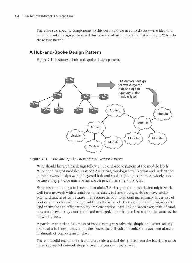
Figure 7-1 illustrates a hub-and-spoke design pattern.
Hierarchical designfollows a layeredhub-and-spoketopology at themodule level.
Module
Module
Module
ModuleModule
Module
Module
ModuleModule
Figure 7-1 Hub and Spoke Hierarchical Design Pattern
Why should hierarchical design follow a hub-and-spoke pattern at the module level? Why not a ring of modules, instead? Aren’t ring topologies well known and understood in the network design world? Layered hub-and-spoke topologies are more widely used because they provide much better convergence than ring topologies.
What about building a full mesh of modules? Although a full mesh design might work well for a network with a small set of modules, full mesh designs do not have stellar scaling characteristics, because they require an additional (and increasingly larger) set of ports and links for each module added to the network. Further, full mesh designs don’t lend themselves to efficient policy implementation; each link between every pair of mod-ules must have policy configured and managed, a job that can become burdensome as the network grows.
A partial, rather than full, mesh of modules might resolve the simple link count scaling issues of a full mesh design, but this leaves the difficulty of policy management along a mishmash of connections in place.
There is a solid reason the tried-and-true hierarchical design has been the backbone of so many successful network designs over the years—it works well.

Chapter 7: Applying Modularity 85
See Chapter 12 , “Building the Second Floor,” for more information on the performance and convergence characteristics of various network topologies.
An Architectural Methodology
Hierarchical network design reaches beyond hub-and-spoke topologies at the module level and provides rules, or general methods of design, that provide for the best overall network design. This section discusses each of these methods or rules—but remember these are generally accepted rules, not hard and fast laws. Part of the art of architecture is knowing when to break the rules.
Assign Each Module One Function
The first general rule in hierarchical network design is to assign each module a single function. What is a “function,” in networking terms?
User Connection: A form of traffic admission control, this is most often an edge function in the network. Here, traffic offered to the network by connected devices is checked for policy errors (is this user supposed to be sending traffic to that ser-vice?), marked for quality of service processing, managed in terms of flow rate, and otherwise prodded to ensure the traffic is handled properly throughout the network.
Service Connection: Another form of traffic admission control, which is most often an edge function as well. Here the edge function can be double sided; however, not only must the network decide what traffic should be accepted from connected devic-es, but it must also decide what traffic should be forwarded toward the services. Stateful packet filters, policy implementations, and other security functions are com-mon along service connection edges.
Traffic Aggregation: Usually occurs at the edge of a module or a subtopology within a network module. Traffic aggregation is where smaller links are combined into bigger ones, such as the point where a higher-speed local area network meets a lower-speed (or more heavily used) wide area link. In a world full of high speed links, aggregation can be an important consideration almost any place in the network. Traffic can be shaped and processed based on the QoS markings given to packets at the network edge to provide effective aggregation services.
Traffic Forwarding: Specifically between modules or over longer geographic dis-tances, this is a function that’s important enough to split off into a separate module; generally this function is assigned to core modules, whether local, regional, or global.
Control Plane Aggregation: This should happen only at module edges. Aggregating control plane information separates failure domains and provides an implementation point for control plane policy.
It might not, in reality, be possible to assign each module in the network one function—a single module might need to support both traffic aggregation at several points, and user or service connection along the module edge. Reducing the number of functions assigned

86 The Art of Network Architecture
to any particular module, however, will simplify the configuration of devices within the module as well as along the module’s edge.
How does assigning specific functionality to each module simplify network design? It’s all in the magic of the Rule of Unintended Consequences. If you mix aggregation of routing information with data plane filtering at the same place in the network, you must deal with not only the two separate policy structures, but also the interaction between the two different policy structures. As policies become more complex, the interaction between the policy spaces also ramps up in complexity.
At some point, for instance, changing a filtering policy at the control plane can interact with filtering policy in the data plane in unexpected ways—and unexpected results are not what you want to see when you’re trying to get a new service implemented during a short downtime interval, or when you’re trying to troubleshoot a broken service at two in the morning. Predictability is the key to solid network operation; predictability and highly interactive policies implemented in a large number of places throughout a network are mutually exclusive in the real world.
All Modules at a Given Level Should Share Common Functionality
The second general rule in the hierarchical method is to design the network modules so every module at a given layer—or a given distance from the network core—has a roughly parallel function. Figure 7-2 shows two networks, one of which does not follow this rule and one which does.
DataCenter
DataCenter
DataCenter
DataCenter
UserAccess
UserAccess
UserAccess
UserAccess
Network 1Illustrating a corrected layering design.
Network 1Illustrating a poor layering design.
UserAccess
UserAccess
UserAccess
UserAccess
ExternalAccess
ExternalAccess
UserAccess
UserAccess
GlobalCore
RegionalCoreRegional
Core
RegionalCore
GlobalCore
RegionalCore
Figure 7-2 Poor and Corrected Hierarchical Layering Designs
Only a few connecting lines make the difference between the poorly designed hierarchical layout and the corrected one. The data center that was connected through a regional core

Chapter 7: Applying Modularity 87
has been connected directly to the global core, a user access network that was connected directly to the global core has been moved so it now connects through a regional core, and the external access module has been moved from the regional core to the global core.
The key point in Figure 7-2 is that the policies and aggregation points should be consis-tent across all the modules of the hierarchical network plan.
Why does this matter?
One of the objectives of hierarchical network design is to allow for consistent configu-ration throughout the network. In the case where the global core not only connects to regional cores, but also to user access modules, the devices in the global core along the edge to this single user access module must be configured in a different way from all the remaining devices. This is not only a network management problem, it’s also a network repair problem—at two in the morning, it’s difficult to remember why the configuration on any specific device might be different and what the impact might be if you change the configuration. In the same way, the single user access module that connects directly to the global core must be configured in different ways than the remaining user access mod-ules. Policy and aggregation that would normally be configured in a regional core must be handled directly within the user edge module itself.
Moving the data center and external access services so that they connect directly into the global core rather than into a regional core helps to centralize these services, allowing all users better access with shorter path lengths. It makes sense to connect them to the global core because most service modules have fewer aggregation requirements than user access modules and stronger requirements to connect to other services within the network.
Frequently, simple changes of this type can have a huge impact on the operational over-head and performance of a network.
Build Solid Redundancy at the Intermodule Level
How much redundancy is there between Modules A and L in the network shown in Figure 7-3 ?
F
G
E
B
A
CD
H
J
K
L
Figure 7-3 Determining Redundancy in a Partial Mesh Topology

88 The Art of Network Architecture
It’s easy to count the number of links—but it’s difficult to know whether each path through this network can actually be considered a redundant path. Each path through the network must be examined individually, down to the policy level, to determine if every module along the path is configured and able to carry traffic between Modules A and L; determining the number of redundant paths becomes a matter of chasing through each available path and examining every policy to determine how it might impact traffic flow. Modifying a single policy in Module E may have the unintended side effect of removing the only redundant path between Modules A and L—and this little problem might not even be discovered until an early morning network outage.
Contrast this with a layered hub and spoke hierarchical layout with well-defined module functions. In that type of network, determining how much redundancy there is between any pair of points in the network is a simple matter of counting links combined with well-known policy sets. This greatly simplifies designing for resilience.
Another way in which a hierarchical design makes designing for resilience easier is by breaking the resilience problem into two pieces—the resilience within a module and the resilience between modules. These become two separate problems that are kept apart through clear lines of functional separation.
This leads to another general rule for hierarchical network design—build solid redundan-cy at the module interconnection points.
Hide Information at Module Edges
It’s quite common to see a purely switched network design broken into three layers—the core, the distribution, and the access—and the design called “hierarchical.” This concept of breaking a network into different pieces and simply calling those pieces different things, based on their function alone, removes one of the crucial pieces of hierarchical design theory: information hiding.
If it doesn’t hide information, it’s not a layer.
Information hiding is crucial because it is only by hiding information about the state of one part of a network from devices in another part of the network that the designer can separate different failure domains. A single switched domain is a single failure domain, and hence it must be considered one single failure domain (or module) from the perspec-tive of a hierarchical design.
A corollary to this is that the more information you can hide, the stronger the separation between failure domains is going to be, as changes in one area of the network will not “bleed over,” or impact other areas of the network. Aggregating or blocking topology information between two sections of the network (as in the case of breaking a spanning tree into pieces or link state topology aggregation at a flooding domain boundary) pro-vides one degree of separation between two failure domains. Aggregating reachability information provides a second degree of separation.
The stronger the separation of failure domains through information hiding, the more sta-bility the information hiding will bring to the network.

Chapter 7: Applying Modularity 89
Typical Hierarchical Design Patterns
There are two traditional hierarchical design patterns: two layer networks and three layer networks. These have been well covered in network design literature (for instance, see Optimal Routing Design), so we will provide only a high level overview of these two design patterns here. Figure 7-4 illustrates two- and three-layer designs.
Core
Core
Distribution
Access
Aggregation
Figure 7-4 Two- and Three-Layer Hierarchical Design Patterns
In the traditional three-layer hierarchical design:
The core is assigned the function of forwarding traffic between different modules within the distribution layer. Little to no control or data plane policy should be con-figured or implemented in the core of a traditional three-layer hierarchical design.
The distribution layer is assigned the functions of forwarding policy and traffic aggregation. Most control plane policy, including the aggregation of reachability and topology information, should be configured in the distribution layer of the tradition-al three layer hierarchical design. Blocking access to specific services, or forwarding plane filtering and policy, should be left out of the distribution layer, however, sim-ply to keep the focus on each module narrow and easy to understand.
The access layer is assigned the functions of user attachment, user traffic aggrega-tion, and data plane policy implementation. The access layer is where you would mark traffic for specific handling through quality of service, block specific sources from reaching specific destinations, and implement other policies of this type.
In the traditional two-layer hierarchical design:
The core is assigned the function of forwarding traffic between different modules within the aggregation layer. The core edge, facing toward the aggregation layer, is also where any policy or aggregation toward the edge of the network is implemented.
The aggregation layer is assigned the functions of user attachment, user traffic aggre-gation, and data plane policy implementation. The aggregation layer is where you would mark traffic for special handling through quality of service, block access to specific services, and otherwise implement packet and flow level filters. The edge of the aggregation layer, facing the core, is also where any policy or aggregation at the control plane is implemented moving from the edge of the network toward the core.

90 The Art of Network Architecture
It’s easy to describe the two-layer network design as simply collapsing the distribution layer into the edge between the core and aggregation layers, or the three-layer design as an expanded two-layer design. Often the difference between the two is sheer size—three-layer designs are often used when the aggregation layer is so large that it would overwhelm the core or require excessive links to the core. Or if it’s used in a campus with multiple buildings containing large numbers of users. Geography often plays a part in choosing a three-layer design, such as a company that has regional cores connecting various sites within a given geographical area, and a global core connecting the various regional cores.
Hierarchical network design doesn’t need to follow one of these design patterns, how-ever. It’s possible to build a hierarchical network using layers of layers, as illustrated in Figure 7-5 .
Aggregation
Core
Figure 7-5 Layers Within Layers
Is the network shown in Figure 7-5 a four-layer design, a three-layer design with two layers within each aggregation module, a three-layer design with the distribution layer collapsed into the core, or a two-layer design with layers within each module? It really doesn’t matter, so long as you’re following the basic rules for hierarchical network design.
Virtualization
Virtualization is a key component of almost all modern network design. From the small-est single campus network to the largest globe-spanning service provider or enterprise, virtualization plays a key role in adapting networks to business needs.
What Is Virtualization?
Virtualization is deceptively easy to define: the creation of virtual topologies (or infor-
mation subdomains) on top of a physical topology. But is it really this simple? Let’s look at some various network situations and determine whether they are virtualization.

Chapter 7: Applying Modularity 91
A VLAN used to segregate voice traffic from other user traffic across a number of physical Ethernet segments in a network
An MPLS-based L3VPN offered as a service by a service provider
An MPLS-based L2VPN providing interconnect services between two data centers across an enterprise network core
A service provider splitting customer and internal routes using an interior gateway protocol (such as IS-IS) paired with BGP
An IPsec tunnel connecting a remote retail location to a data center across the public Internet
A pair of physical Ethernet links bonded into a single higher bandwidth link between two switches
The first three are situations just about any network engineer would recognize as virtu-alization. They all involve full-blown technologies with their own control planes, tunnel-ing mechanisms to carry traffic edge to edge, and clear-cut demarcation points. These are the types of services and configurations we normally think of when we think of virtualization.
What about the fourth situation—a service provider splitting routing information between two different routing protocols in the same network? There is no tunneling of traffic from one point in the network to another, but is tunneling really necessary in order to call a solution “virtualization”? Consider why a service provider would divide routing information into two different domains. Breaking up networks in this way creates mul-tiple mutually exclusive sets of information within the networks. The idea is that internal and external routing information should not be mixed. A failure in one domain is split off from a failure in another domain (just like failures in one module of a hierarchical design are prevented from leaking into a second module in the same hierarchical design), and policy is created that prevents reachability to internal devices from external sources.
All these reasons and results sound like modularization in a hierarchical network. Thus, it only makes sense to treat the splitting of a single control plane to produce mutually exclusive sets of information as a form of virtualization. To the outside world, the entire network appears to be a single hop, edge-to-edge. The entire internal topology is hid-den within the operation of BGP—hence there is a virtual topology, even if there is no tunneling.

92 The Art of Network Architecture
The fifth situation, a single IPsec tunnel from a retail store location into a data center, seems like it might even be too simple to be considered a case of virtualization. On the other hand, all the elements of virtualization are present, aren’t they? We have the hid-ing of information from the control plane—the end site control plane doesn’t need to be aware of the topology of the public Internet to reach the data center, and the routers along the path through the public Internet don’t know about the internal topology of the data center to which they’re forwarding packets. We have what is apparently a point-to-point link across multiple physical hops, so we also have a virtual topology, even if that topology is limited to a single link.
The answer, then, is yes, this is virtualization. Anytime you encounter a tunnel, you are encountering virtualization—although tunneling isn’t a necessary part of virtualization.
With the sixth situation—bonding multiple physical links into a single Layer 2 link con-necting two switches—again we have a virtual link that runs across multiple physical links, so this is virtualization as well.
Essentially, virtualization appears anytime we have the following:
A logical topology that appears to be different from the physical topology
More than one control plane (one for each topology), even if one of the two control planes is manually configured (such as static routes)
Information hiding between the virtual topologies
Is MPLS Tunneling?
Is MPLS a tunneling technology? There has been a debate raging on this very topic for years within the network community, and there doesn’t seem to be a clear-cut answer to the question. MPLS acts like a tunneling technology in the addition of headers between the Layer 3 transport and Layer 2 MAC headers. On the other hand, some forms of data can be placed directly into an MPLS frame and carried across an MPLS-enabled network as if MPLS were the data link layer.
The answer must be both yes and no. Tunneling is a matter of usage, rather than a matter of packet formatting. If someone built a device that switched purely on GRE headers, rather than on the outer IP packet normally carried within a GRE packet, we’d be in the same position with GRE as we are with MPLS.
When it’s used as an inner header between IP and some data link layer, and when the local control plane doesn’t understand the final destination—only the intermediate hops along the way—MPLS is clearly being used to tunnel. When it’s used as an outer header, and the header is directly used to switch the packet (and even rewritten at each hop like all other layer two MAC headers), it’s clearly not.
In most MPLS deployments, then, MPLS is both a tunneling protocol (the inner header) and not (the outer header). In both cases, MPLS is used to build virtual topologies on top of physical topologies (just like IP and a host of other protocols), so it’s still a virtualization technique whether or not it’s used to tunnel packets.

Chapter 7: Applying Modularity 93
Virtualization as Vertical Hierarchy
One way of looking at virtualization is as vertical hierarchy as Figure 7-6 illustrates.
G
A
CoreModuleB
C D
E
F
A’
B’
C’ D’
E’
F’
H
L
J
K
Figure 7-6 Virtualization as Vertical Hierarchy
In this network, Routers A through F are not only a part of the physical topology, they are also part of a virtual topology, shown offset and in a lighter shade of gray. The pri-mary topology is divided into three modules:
Routers A, B, G, and H
Routers C, D, J, and K (the network core)
Routers E, F, and L
What’s important to note is that the virtual topology cuts across the hierarchical modules in the physical topology, overlaying across all of them, to form a separate information domain within the network. This virtual topology, then, can be seen as yet another mod-ule within the hierarchical system—but because it cuts across the modules in the physical topology, it can be seen as “rising out of” the physical topology—a vertical module rath-er than a topological module, built on top of the network, cutting through the network.
How does seeing virtualization in this way help us? Being able to understand virtualiza-tion in this way allows us to understand virtual topologies in terms of the same require-ments, solutions, and problems as hierarchical modules. Virtualization is just another mechanism network designers can use to hide information.
Why We Virtualize
What business problem can we solve through virtualization? If you listen to the chatter in modern network design circles, the answer is “almost anything.” But like any overused tool (hammer, anyone?), virtualization has some uses for which it’s very apt and others for which it’s not really such a good idea. Let’s examine two specific use cases.

94 The Art of Network Architecture
Communities of Interest
Within any large organization there will invariably be multiple communities of interest—groups of users who would like to have a small part of the network they can call their own. This type of application is normally geared around the ability to control access to specific applications or data so only a small subset of the entire organization can reach these resources.
For instance, it’s quite common for a human resources department to ask for a relatively secure “network within the network.” They need a way to transfer and store informa-tion without worrying about unauthorized users being able to reach it. An engineering, design, or animation department might have the same requirements for a “network within the network” for the same reasons.
These communities of interest can often best be served by creating a virtual topology that only people within this group can access. Building a virtual topology for a community of interest can, of course, cause problems with the capability to share common resources—see the section “Consequences of Network Virtualization” later in the chapter.
Network Desegmentation
Network designers often segment networks by creating modules for various reasons (as explained in the previous sections of this chapter). Sometimes, however, a network can be unintentionally segmented. For instance, if the only (or most cost effective) way to con-nect a remote site to a headquarters or regional site is to connect them both to the public Internet, the corporate network is now unintentionally segmented. Building virtual net-works that pass over (over the top of) the network in the middle is the only way to deseg-ment the network in this situation.
Common examples here include the following:
Connecting two data centers through a Layer 3 VPN service (provided by a service provider)
Connecting remote offices through the public Internet
Connecting specific subsets of the network between two partner networks con-nected through a single service provider
Separation of Failure Domains
As we’ve seen in the first part of this chapter, designers modularize networks to break large failure domains into smaller pieces. Because virtualization is just another form of hiding information, it can also be used to break large failure domains into smaller pieces.
A perfect example of this is building a virtual topology for a community of interest that has a long record of “trying new things.” For instance, the animation department in a large entertainment company might have a habit of deploying new applications that sometimes adversely impact other applications running on the same network. By first

Chapter 7: Applying Modularity 95
separating a department that often deploys innovative new technology into its own com-munity of interest, or making it a “network within the network,” the network designer can reduce or eliminate the impact of new applications deployed by this one department.
Another version of this is the separation of customer and internal routes across two sepa-rate routing protocols (or rather two different control planes) by a service provider. This separation protects the service provider’s network from being impacted by modifications in any particular customer’s network.
Consequences of Network Virtualization
Just as modularizing a network has negative side effects, so does virtualization—and the first rule to return to is the one about hiding information and its effect on stretch in networks. Just as aggregation of control plane information to reduce state can increase the stretch in a network (or rather cause the routing of traffic through a network to be suboptimal), virtualization’s hiding of control plane information has the same potential effect. To understand this phenomenon, take a look at the network in Figure 7-7 .
A
B
CD
E
F
A’
C’
D’ E’F’
G
H
Figure 7-7 Example of Stretch Through Virtualized Topologies
In this case, host G is trying to reach a service on a server located in the rack repre-sented by H. If both the host and the server were on the same virtual topology, the path between them would be one hop. Because they are on different topologies, however, traf-fic between the two devices must travel to the point where the two topologies meet, at Router F/F’, to be routed between the two topologies (to leak between the VLANs).
If there are not services that need to be reached by all the hosts on the network, or each virtual topology acts as a complete island of its own, this problem may not arise in this specific form. But other forms exist, particularly when traffic must pass through filtering and other security devices while traveling through the network, or in the case of link or device failures along the path.
A second consequence of virtualization is fate sharing . Fate sharing exists anytime there are two or more logical topologies that share the same physical infrastructure—so fate sharing and virtualization go hand in hand, no matter what the physical layer and logical overlays look like. For instance, fate sharing occurs when several VLANs run across the same physical Ethernet wire, just as much as it occurs when several L3VPN circuits run
96 The Art of Network Architecture
across the same provider edge router or when multiple frame relay circuits are routed across a single switch. There is also fate sharing purely at the physical level, such as two optical strands running through the same conduit. The concepts and solutions are the same in both cases.
To return to the example in Figure 7-7 , when the link between Routers E and F fails, the link between Routers E’ and F’ also fails. This may seem like a logical conclusion on its face, but fate sharing problems aren’t always so obvious, or easy to see.
The final consequence of virtualization isn’t so much a technology or implementation problem as it is an attitude or set of habits on the part of network engineers, designers, and architects. RFC1925, rule 6, and the corollary rule 6a, state: “It is easier to move a problem around (for example, by moving the problem to a different part of the overall network architecture) than it is to solve it. ...It is always possible to add another level of indirection.”
In the case of network design and architecture, it’s often (apparently) easier to add another virtual topology than it is to resolve a difficult and immediately present problem. For instance, suppose you’re deploying a new application with quality of service requirements that will be difficult to manage alongside existing quality of service configurations. It might seem easier to deploy a new topology, and push the new application onto the new topology, than to deal with the complex quality of service problems. Network architects need to be careful with this kind of thinking, though—the complexity of multiple virtual topologies can easily end up being much more difficult to manage than the alternative.
Final Thoughts on Applying Modularity
Network modularization provides clear and obvious points at which to configure and manage policy, clear trade-offs between state and stretch, and predictable reactions with-in the network to specific changes in the network topology. The general rules for using hierarchical design are as follows:
Break the network into modules, using information hiding to divide module from module. Layer edges exist only where information is hidden.
Assign each module as few functions as possible to promote clarity and repeatability in configurations, and reduce the unintended consequences of complex policy interactions.
Build networks using hub-and-spoke configurations of modules.
All modules at a given layer within a network should have similar functionality to promote ease of troubleshooting and reduce configuration complexity.
Build solid redundancy at module interconnection points.
Overall, remember to be flexible with the modularization. Rather than focusing on a single design pattern as the solution to all design problems, focus on finding the best fit for the problem at hand.

This page intentionally left blank

Index
A
AAA (Authorization, Authentication, and Accounting) services, 138
ABR (Area Border Router), 79
access
separating network access from applica-tion access, 244 - 245
unifying through remote access solu-tions, 248 - 249
acquisitions, 14 - 15
action (OODA), 125
aggregating
reachability information, 78
topology information, 78
application layer, 37 , 39
applications
application access, separating from net-work access, 244 - 245
application services, 260
network requirements, 5 - 6
Arbor security report, 122
architectural methodology, 85
architecture, defining, xx - xxi
assigning each module one function, 85 - 86
common functionality, 86 - 87
information hiding, 88
redundancy, 87 - 88
Area Border Router (ABR), 79
art of network architecture, xxii
assigning each module one function, 85 - 86
Augmented model (SDNs), 268 - 269
authentication
Authorization, Authentication, and Accounting (AAA) services, 138
BYOD (Bring Your Own Device), 25
Authorization, Authentication, and Accounting (AAA) services, 138
automation, brittleness of, 125 - 126
availability (network), 98 - 99
avoiding silos, xxi - xxii
B
Bailey, Stuart, 214
bandwidth, QoS (quality of service) and, 60 - 61
baselines, 116
BC (business continuity). See business continuity

304 best path
best path
calculating, 106
switching to new best path, 107
BFD (Bidirectional Forwarding Detection), 58
BGP (Border Gateway Protocol), 206 - 207
complexity
of place, 208
of policy, 208 - 209
of purpose, 207 - 208
iBGP Core (Core and Aggregation Model), 210 - 212
iBGP Edge-to-Edge (Overlay Model), 209 - 210
Bidirectional Forwarding Detection (BFD), 58
border leaf, 291
Boyd, John, 118
Bring Your Own Device (BYOD)
design considerations, 27
options, 24 - 26
overview, 24
brittleness, 125 - 126
building defense in, 126
modularization, 128 - 129
resilience, 118 - 129
unintended consequences, 127
business continuity, 29
design considerations, 31 - 33
versus disaster recovery, 29
planning, 30 - 31
real world applications, 29
business environment, 1 - 3
big picture, 3 - 4
business case for mobility
campus bus service example, 228 - 229
mobile retail analysis team, 229 - 230
shifting load, 230
business factors driving technology, 1 - 3
applications, 5 - 6
big picture, 3 - 4
competition, 4 - 5
external users, 8 - 9
guest users, 9
internal users, 7 - 8
network evaluation, 6
business operations, improving, 19
business continuity, 29 - 33
BYOD (Bring Your Own Device), 24 - 28
workflow, 19 - 24
competition, 4 - 5
divestments, 14 - 15
impact analysis, 31
mergers and acquisitions, 14 - 15
reliance on networks, 1 - 2
technology driving business, 9 - 10
business operations, improving, 19
business continuity, 29
design considerations, 31 - 33
versus disaster recovery, 29
planning, 30 - 31
real world applications, 29
BYOD (Bring Your Own Device)
design considerations, 27
options, 24 - 26
overview, 24
policy, 28
person-to-person communication, 21
workflow, 19 - 20
design decisions, 23 - 24
machine-to-machine communica-tion, 22 - 23
matching data flow and network design, 20 - 21
person-to-machine communica-tion, 21 - 22
complexity 305
BYOD (Bring Your Own Device)
design considerations, 27
options, 24 - 26
overview, 24
policy, 28
C
calculating new best path, 106
campus bus service example, 228 - 229
capacity planning for Clos networks, 160 - 161
CEF (Cisco Express Forwarding), 52
centralization, 15 - 17
change management, 136
choosing
IP-centric mobility solutions, 243 - 244
remote access solutions, 249
routing protocols, 200 - 202
Cisco Express Forwarding (CEF), 52
Cisco Global Escalation Team, 127
Cisco OnePK, 270
Cisco Security reports, 122
clearly assigned functionality, 74 - 75
CLNP (Connectionless Networking Protocol), 36
Clos networks, 55 , 157 - 161
capacity planning, 160 - 161
control planes, 159 - 160
cloud-based solutions, 245
advantages of, 257 - 258
application services, 260
commoditization, 254 - 255
components, 262 - 264
content distribution, 259
costs, 255 - 256
database services, 260
deploying, 261
data mobility, 261
network connections, 261 - 262
security, 262
systemic interactions, 262
history of, 252 - 254
network services, 260 - 261
overview, 251 - 252
risks, 256 - 257
storage, 258 - 259
collection, loosening connection between collection and management, 140 - 141
co-located data centers, 16
commoditization of computing power and storage, 254 - 255
common functionality across modules, 86 - 87
communication
machine-to-machine communication, 22 - 23
person-to-machine communication, 21 - 22
person-to-person communication, 21
communities of interest, 94
competition, 4 - 5
complexity, 128
BGP
complexity of place, 208
complexity of policy, 208 - 209
complexity of purpose, 207 - 208
control plane policy dispersion, 218 - 220
control plane state, 209 , 213
concepts, 214 - 215
configuration state, 217 - 218
network stretch, 215 - 217
data plane state, 220 - 222
disjoint parallel planes, 164
managing complexity trade-offs, 224 - 226
overview, 213
reaction time, 223 - 224

306 complexity
SDNs (Software-Defined Networks), 279
separating complexity from complexity, 72 - 73
single complexity number, 225
configuration of routing protocols, 197 - 198
configuration state, 217 - 218
connection-oriented protocols, 41 - 42
Connectionless Networking Protocol (CLNP), 36
connectionless protocols, 41 - 42
content distribution, cloud-based solu-tions, 259
continuity, 29
design considerations, 31 - 33
versus disaster recovery, 29
planning, 30 - 31
real world applications, 29
control planes
aggregation, 85
Clos networks, 159 - 160
convergence
fast convergence techniques, 104 - 108
limits on, 100 - 101
data center design, 295 - 299
Layer 2, 295
Layer 3, 296 - 299
DNS (Domain Name System), 43
explained, 42 - 43
interaction between control planes, 49 - 51 , 177 - 178
measuring, 143 - 144
MPLS-based L3VPNs, 186 - 187
network measurement and management, 49
network metadata, 46
physical versus topological locations, 44 - 45
policy dispersion, 218 - 220
QoS (quality of service), 48 - 49
reactive versus proactive systems, 51 - 53
routing, 45 - 48
SDNs (Software-Defined Networks)
reactive control planes, 280
separation of data and control planes, 279 - 280
state, 213
concepts, 214 - 215
configuration state, 217 - 218
network stretch, 215 - 217
STP (Spanning Tree Protocol), 61 - 62
VXLAN, 190
convergence
fast convergence techniques, 104 - 108
calculating new best path, 106
detecting topology change, 104 - 105
impact of, 107 - 108
propagating information about the change, 105 - 106
switching to new best path, 107
limits on control plane convergence, 100 - 101
reaction time, 223 - 224
ring toplogy, 151 - 154
routing protocols, 194 - 196
Core and Aggregation Model (BGP), 209
costs
cloud-based solutions, 255 - 256
network costs, justifying, 134 - 135
remote access solutions, 248
cube topologies, 166 - 167
customers
external users, 8 - 9
guest users, 9
internal users, 7 - 8

desegmentation 307
D
data center design
control plane issues, 295 - 299
Layer 2, 295
Layer 3, 296 - 299
modularity, 300 - 301
network virtualization, 299
overview, 287
spine and leaf fabrics, 287 - 294
border leaf, 291
explained, 288 - 291
oversubscription, 294
sizing, 291 - 294
traffic flow, 290
storage, 299 - 300
data center environments
centralization, 15 - 17
co-located data centers, 16
data center design
control plane issues, 295 - 299
network virtualization, 299
overview, 287
spine and leaf fabrics, 287 - 294
decentralization, 15 - 17
SDNs (Software-Defined Networks), 281 - 283
storage, 299 - 300
data flow, matching with network design, 20 - 21
data link layer, 37
data mobility, cloud-based solutions, 261
data plane interaction, 176 - 177
data plane state, 220 - 222
database services, cloud-based solutions, 260
Day, John, 40
DDNS (Dynamic DNS), 242 - 243
decentralization, 15 - 17
decisions (OODA), 124 - 125
decline, organic growth and, 12 - 14
decreasing
MTBM (Mean Time Between Mistakes), 136
MTTR (Mean Time to Repair), 136
defense, building in, 126 . See also secu-rity
modularization, 128 - 129
resilience, 118 - 129
unintended consequences, 127
defining architecture, xx - xxi
Denial of Service (DoS) attacks, 268
deploying
BGP, 209
iBGP Core (Core and Aggregation Model), 210 - 212
iBGP Edge-to-Edge (Overlay Model), 209 - 210
cloud-based solutions, 261 - 262
data mobility, 261
network connections, 261 - 262
security, 262
systemic interactions, 262
IPv6
EIGRP interaction, 206
IS-IS interaction, 204 - 205
OSPF interaction, 205 - 206
policy edges, 203 - 204
shape of deployment, 202
topological deployment, 203
virtual topology deployment, 203
management
loosening connection between collection and management, 140 - 141
sampling considerations, 141 - 142
Depth First Search (DFS), 115
desegmentation, 94

308 design
design, 11 - 12 . See also modularity; physi-cal layer; topology
business continuity, 31 - 33
centralization, 15 - 17
complexity, 128
BGP, 207 - 209
control plane policy dispersion, 218 - 220
control plane state, 209 , 213 - 218
data plane state, 220 - 222
disjoint parallel planes, 164
managing complexity trade-offs, 224 - 226
overview, 213
reaction time, 223 - 224
single complexity number, 225
data center design
control plane issues, 295 - 299
modularity, 300 - 301
network virtualization, 299
overview, 287
spine and leaf fabrics, 287 - 294
storage, 299 - 300
decentralization, 15 - 17
divestments, 14 - 15
hierarchical design, 83 - 84
hub-and-spoke design pattern, 84 - 85
layers within layers, 90
rules for, 96
three-layer hierarchical design, 89
two-layer hierarchical design, 89 - 90
virtualization as vertical hierar-chy, 93
matching data flow and network design, 20 - 21
mergers and acquisitions, 14 - 15
organic growth and decline, 12 - 14
queue designs, 221
resilience and
overview, 97
redundancy, 98 - 104
TRILL (Transparent Interconnection of Lots of Links), 64 - 65
detecting topology change, 104 - 105
DFS (Depth First Search), 115
diagrams, 144 - 145
disaster recovery, 29
disjoint parallel planes, 162 - 163
advantages of, 163 - 164
complexity, 164
when to use, 164
distributed computing, 252
Distributed model (SDNs), 267 - 268
divergent data planes, 165 - 166
divestments, 14 - 15
DLLs (Dynamically Linked Libraries), 264
DNS (Domain Name System), 43
documentation, 116 , 144 - 145
Domain Name System (DNS), 43
domains
Domain Name System (DNS), 43
failure domains
explained, 72
security, 128
separation of, 94 - 95
splitting horizontally and verti-cally, 79 - 81
DoS (Denial of Service) attacks, 268
DR (disaster recovery), 29
Dynamic DNS (DDNS), 242 - 243
Dynamically Linked Libraries (DLLs), 264
E
edge ports, 292 - 293
EIGRP interaction with IPv6, 206

frameworks (SDN) 309
encapsulation, layered, 171
End-to-End QoS, Second Edition (Szigeti), 61
end-to-end/network performance, mea-suring, 142 - 143
Enhanced Telecommunications Operations Map (ETOM), 137
Ethernet, 37 , 39
ETOM (Enhanced Telecommunications Operations Map), 137
evaluating current state of network, 6
event driven notifications, 104
external users, 8 - 9
F
FAB (Fulfillment, Assurance, and Billing) model, 137
FabricPath, 65
fabrics, 65
spine and leaf fabrics, 287 - 294
border leaf, 291
explained, 288 - 291
oversubscription, 294
sizing, 291 - 294
traffic flow, 290
toroid fabrics, 167 - 168
failure domains
explained, 72
measuring, 143 - 144
security, 128
separation of, 94 - 95
splitting horizontally and vertically, 79 - 81
failure of network links, 57 - 58
fast convergence techniques, 104 - 108
calculating new best path, 106
detecting topology change, 104 - 105
impact of, 107 - 108
propagating information about the change, 105 - 106
switching to new best path, 107
Fast Reroute (FRR), 108 - 109 , 154 - 155 , 223 - 224
LFA (Loop Free Alternates)
explained, 110
remote Loop-Free Alternatives, 110 - 111
MRTs (Maximally Redundant Trees), 113 - 114
Not-Via Fast Reroute, 111 - 113
P/Q space, 109 - 110
when to use, 114
Fault, Configuration, Accounting, Performance, and Security (FCAPS), 137 - 138
FCAPS (Fault, Configuration, Accounting, Performance, and Security), 137 - 138
FCoE (Fibre Channel over Ethernet), 22 , 300
feedback loops, 70 , 102 - 103
FIB (forwarding table), 275
Fibre Channel over Ethernet (FCoE), 22 , 300
filtering router information, 79
flexibility in remote access solutions, 246
forwarding table (FIB), 275
four-layer model, 38 - 39
frameworks (SDN), 266
Augmented model, 268 - 269
Cisco OnePK, 270
Distributed model, 267 - 268
Hybrid model, 269 - 270
I2RS (Interface to the Routing System), 270
OR/OR (Offline Routing/Online Reaction), 272 - 274
OpenFlow, 274 - 276 , 281 - 283
Replace model, 271
310 FRR (Fast Reroute)
FRR (Fast Reroute), 108 - 109 , 223 - 224
LFA (Loop Free Alternates)
explained, 110
remote Loop-Free Alternatives, 110 - 111
MRTs (Maximally Redundant Trees), 113 - 114
Not-Via Fast Reroute, 111 - 113
P/Q space, 109 - 110
when to use, 114
Fulfillment, Assurance, and Billing (FAB) model, 137
full mesh topology, 154 - 157
functions
assigning each module one function, 85 - 86
common functionality across modules, 86 - 87
control plane aggregation, 85
service connections, 85
traffic aggregation, 85
traffic forwarding, 85
user connections, 85
G
Grossman, Robert L., 214
growth, organic, 12 - 14
guest users, 9
H
hiding information
failure domains, 79 - 81
at module edges, 88
overview, 71
topology and reachability, 77 - 79
hierarchical design, 83 - 84
architectural methodology, 85
assigning each module one func-
tion, 85 - 86
common functionality, 86 - 87
information hiding, 88
redundancy, 87 - 88
hub-and-spoke design pattern, 84 - 85
layers within layers, 90
rules for, 96
three-layer hierarchical design, 89
two-layer hierarchical design, 89 - 90
virtualization as vertical hierarchy, 93
history of cloud-based computing,
252 - 254
horizontal information hiding, 79 - 81
host routing, IP-centric mobility solu-
tions, 239 - 240
hub-and-spoke design pattern, 84 - 85
human level information overload
overview, 73 - 74
repeatable configurations, 75
human side of resilience, 114 - 116
hybrid model
DNS (Domain Name System), 43
explained, 42 - 43
interaction between control planes, 49 - 51
network measurement and management, 49
network metadata, 46
physical versus topological locations, 44 - 45
QoS (quality of service), 48 - 49
routing, 45 - 48
SDNs (Software-Defined Networks), 269 - 270
Cisco OnePK, 270
I2RS (Interface to the Routing System), 270
hypercubes, 167
Internet Protocol (IP) 311
I
I2RS (Interface to the Routing System), 270
iBGP Core (Core and Aggregation Model), 210 - 212
iBGP Edge-to-Edge (Overlay Model), 209 - 210
iDefense reports, 122
Identifier-Locator Network Protocol (ILNP), 235 - 236
IEEE 802.1aq, 65
ILNP (Identifier-Locator Network Protocol), 235 - 236
image manager, 263
improving business operations, 19
business continuity, 29
design considerations, 31 - 33
versus disaster recovery, 29
planning, 30 - 31
real world applications, 29
BYOD (Bring Your Own Device)
design considerations, 27
options, 24 - 26
overview, 24
policy, 28
person-to-person communication, 21
workflow, 19 - 20
design decisions, 23 - 24
machine-to-machine communica-tion, 22 - 23
matching data flow and network design, 20 - 21
person-to-machine communica-tion, 21 - 22
information hiding, 79 - 81
failure domains, splitting horizontally and vertically, 79 - 81
at module edges, 88
overview, 71
topology and reachability, 77 - 79
aggregating reachability informa-tion, 78
aggregating topology information, 78
filtering router information, 79
information overload
human level information overload
clearly assigned functionality, 74 - 75
overview, 73 - 74
repeatable configurations, 75
machine level information overload
definition of, 69
overview, 68
reducing, 71
separating complexity from com-plexity, 72 - 73
Ingress Tunnel Router (ITR), 237
Interface to the Routing System (I2RS), 270
interface/transport, measuring, 143
Intermediate System to Intermediate System (IS-IS), 36 , 204 - 205
intermodule level, redundancy at, 87 - 88
internal users, 7 - 8
Internet layer, 39
Internet Protocol (IP), 38 - 39
IP SLA (IP Service Level Agreement), 58
IP-centric mobility solutions, 234 - 235
choosing, 243 - 244
DDNS (Dynamic DNS), 242 - 243
host routing, 239 - 240
ILNP (Identifier-Locator Network Protocol), 235 - 236
LISP (Locator Identifier Separation Protocol), 237 - 238

312 Internet Protocol (IP)
MANETs (Mobile Ad-Hoc Networks), 240 - 242
Mobile IP, 238 - 239
interVLAN routing, 297
IP (Internet Protocol), 38 - 39
IP Service Level Agreement (IP SLA), 58
IP-centric mobility solutions, 234 - 235
choosing, 243 - 244
DDNS (Dynamic DNS), 242 - 243
host routing, 239 - 240
ILNP (Identifier-Locator Network Protocol), 235 - 236
LISP (Locator Identifier Separation Protocol), 237 - 238
MANETs (Mobile Ad-Hoc Networks), 240 - 242
Mobile IP, 238 - 239
IPsec, 38
IPv6 deployment
EIGRP interaction, 206
IS-IS interaction, 204 - 205
OSPF interaction, 205 - 206
policy edges, 203 - 204
shape of deployment, 202
topological deployment, 203
virtual topology deployment, 203
IS-IS (Intermediate System to Intermediate System), 36 , 204 - 205
iSCSI, 22 , 300
ISO 10400. See FCAPS (Fault, Configuration, Accounting, Performance, and Security)
iterative layering model, 39 - 42
ITR (Ingress Tunnel Router), 237
J-K-L
Juniper's Q Fabric, 65
justifying cost of network, 134 - 135
Layer 2 data centers, 295
Layer 3 data centers, 296 - 299
layered encapsulation, 171
layers (network)
four-layer model, 38 - 39
iterative layering model, 39 - 42
layers within layers, 90
seven-layer model, 37 - 38
state, 233 - 234
leaf fabrics. See spine and leaf fabrics
Learning Tools Interoperability (LTI), 245
LFA (Loop Free Alternates), 51
explained, 110
remote Loop-Free Alternatives, 110 - 111
link layer, 39
links, 57
link failure, 57 - 58
QoS (quality of service), 59 - 61
marketing packets, 59
queues and rate limiters, 59 - 60
speed and bandwidth, 60 - 61
TRILL (Transparent Interconnection of Lots of Links), 62
in design landscape, 64
operation, 62 - 64
virtualization, 58 - 59
LISP (Locator Identifier Separation Protocol), 237 - 238
Locator Identifier Separation Protocol (LISP), 237 - 238
Loop Free Alternates (LFA), 51
explained, 110
remote Loop-Free Alternatives, 110 - 111
loosening connection between collection and management, 140 - 141
LTI (Learning Tools Interoperability), 245

mobility 313
M
machine level information overload
definition of, 69
overview, 68
reducing, 71
separating complexity from complexity, 72 - 73
machine-to-machine communication, 22 - 23
management, 133
change management, 136
complexity trade-offs, 224 - 226
deploying, 140 - 141
documentation, 144 - 145
hybrid model, 49
measurement
end-to-end/network, 142 - 143
failure domain/control plane,
143 - 144
interface/transport, 143
model of, 142
models, 137
FCAPS (Fault, Configuration,
Accounting, Performance, and
Security), 137 - 138
OODA (Observe, Orient, Decide,
Act) loop, 138 - 140
reasons for, 133
decreasing MTBM (Mean Time
Between Mistakes), 136
decreasing MTTR (Mean Time to
Repair), 136
justifying cost of network,
134 - 135
planning, 135 - 136
sampling considerations, 141 - 142
MANETs (Mobile Ad-Hoc Networks),
240 - 242
marketing packets, 59
matching data flow and network design,
20 - 21
matching routing protocols to topology,
199 - 200
Maximally Redundant Trees (MRTs),
113 - 114
Maximum Transmission Unit (MTU), 58 ,
176 - 177 , 183
MDM (Mobile Device Managers), 26
Mean Time Between Failures (MTBF),
98 - 100
Mean Time Between Mistakes (MTBM), 136
Mean Time to Repair (MTTR), 98 - 100 , 103 - 104 , 136
Mean Time to Repeat (MTTR), 75 - 77
measurement
end-to-end/network, 142 - 143
failure domain/control plane, 143 - 144
hybrid model, 49
interface/transport, 143
model of, 142
mergers, 14 - 15
mesh design, 84 , 87 - 88
MGRE (Multipoint Generic Routing Encapsulation), 58
Microsoft Security Intelligence Report, 122
Mobile Ad-Hoc Networks (MANETs), 240 - 242
Mobile Device Managers (MDM), 26
Mobile IP, 238 - 239
mobile retail analysis team, 229 - 230
mobility
business case for
campus bus service example, 228 - 229
mobile retail analysis team, 229 - 230
shifting load, 230

314 mobility
cloud-based solutions, 245
advantages of, 257 - 258
application services, 260
commoditization, 254 - 255
components, 262 - 264
content distribution, 259
costs, 255 - 256
database services, 260
deploying, 261 - 262
history of, 252 - 254
network services, 260 - 261
overview, 251 - 252
risks, 256 - 257
storage, 258 - 259
IP-centric mobility solutions, 234 - 235
choosing, 243 - 244
DDNS (Dynamic DNS), 242 - 243
host routing, 239 - 240
ILNP (Identifier-Locator Network Protocol), 235 - 236
LISP (Locator Identifier Separation Protocol), 237 - 238
MANETs (Mobile Ad-Hoc Networks), 240 - 242
Mobile IP, 238 - 239
overview, 227
remote access solutions, 244
choosing, 249
costs, 248
flexibility, 246
separating network access from application access, 244 - 245
unifying all access through, 248 - 249
VDI (Virtual Desktop Interface), 247
speed requirements, 231
state
network layers, 233 - 234
requirements, 231
topological locations, 232 - 233
models
FCAPS (Fault, Configuration, Accounting, Performance, and Security), 137 - 138
four-layer model, 38 - 39
hybrid model
control plane, 43 - 46
explained, 42 - 43
interaction between control planes, 49 - 51
network measurement and man-agement, 49
network metadata, 46
QoS (quality of service), 48 - 49
routing, 45 - 46
iterative layering model, 39 - 42
network measurement, 142
OODA (Observe, Orient, Decide, Act) loop, 138 - 140
overview, 35 - 36
PINs (Places In the Network), 54 - 56
reactive versus proactive systems, 51 - 53
SDNs (Software-Defined Networks)
Augmented model, 268 - 269
Cisco OnePK, 270
Distributed model, 267 - 268
Hybrid model, 269 - 270
I2RS (Interface to the Routing System), 270
OpenFlow, 274 - 276 , 281 - 283
OR/OR (Offline Routing/Online Reaction), 272 - 274
Replace model, 271
seven-layer model, 36 - 38
waterfall model, 53 - 54
modularity
architectural methodology, 85
assigning each module one func-tion, 85 - 86
common functionality, 86 - 87

multitenant data centers 315
information hiding, 88
redundancy, 87 - 88
building defense in, 128 - 129
data center design, 300 - 301
failure domains
explained, 72
security, 128
separation of, 94 - 95
splitting horizontally and verti-cally, 79 - 81
hierarchical design, 83 - 84
hub-and-spoke design pattern, 84 - 85
layers within layers, 90
rules for, 96
three-layer hierarchical design, 89
two-layer hierarchical design, 89 - 90
human level information overload
clearly assigned functionality, 74 - 75
overview, 73 - 74
repeatable configurations, 75
information hiding
overview, 71
splitting failure domains horizon-tally and vertically, 79 - 81
topology and reachability, 77 - 79
machine level information overload
definition of, 69
overview, 68
reducing, 71
MTTR (Mean Time to Repair), 75 - 77
optimization, 81 - 82
overview, 67 - 68
separating complexity from complexity, 72 - 73
tunneling, 177 - 178
virtualization
consequences of, 95 - 96
data plane interaction, 176 - 177
explained, 90 - 92
multicast, 179 - 180
reasons for, 93 - 95
scaling, 178 - 179
security, 180 - 182
as vertical hierarchy, 93
MPLS (Multiprotocol Label Switching), 91
MPLS-based L3VPNs, 182
advantages and disadvantages, 188 - 189
control plane interaction, 186 - 187
MTU (Maximum Transmission Unit), 183
multicast, 188
operational overview, 182 - 185
QoS (quality of service), 186
scaling, 187 - 188
security, 188
supported traffic, 183
tunneling, 173 - 175
MRTs (Maximally Redundant Trees), 113 - 114
MTBF (Mean Time Between Failures), 98 - 100
MTBM (Mean Time Between Mistakes), 136
MTTR (Mean Time to Repair), 75 - 77 , 98 - 100 , 103 - 104 , 136
MTU (Maximum Transmission Unit), 58 , 176 - 177 , 183
multicast, 179 - 180 , 188
Multipoint Generic Routing Encapsulation (MGRE), 58
Multiprotocol Label Switching. See MPLS (Multiprotocol Label Switching)
multitenant data centers, 16

316 NAT (Network Address Translation)
N
NAT (Network Address Translation), 234
ND (Neighbor Discovery), 240
Neighbor Discovery (ND), 240
“NetComplex: A Complexity Metric for Networked System Designs” (Chun, Ratnasamy, and Kohler), 222
network access, separating from applica-tion access, 244 - 245
Network Address Translation (NAT), 234
network availability, 98 - 99
“A Network Complexity Index for Networks of Networks” (Bailey and Grossman), 214
network connections, cloud-based solu-tions, 261 - 262
network convergence, 69
network desegmentation, 94
network design, 11 - 12 . See also modular-ity; physical layer; topology
business continuity, 31 - 33
centralization, 15 - 17
complexity, 128
BGP, 207 - 209
control plane policy dispersion, 218 - 220
control plane state, 209 , 213 - 218
data plane state, 220 - 222
disjoint parallel planes, 164
managing complexity trade-offs, 224 - 226
overview, 213
reaction time, 223 - 224
single complexity number, 225
data center design
control plane issues, 295 - 299
modularity, 300 - 301
network virtualization, 299
overview, 287
spine and leaf fabrics, 287 - 294
storage, 299 - 300
decentralization, 15 - 17
divestments, 14 - 15
matching data flow and network design, 20 - 21
mergers and acquisitions, 14 - 15
organic growth and decline, 12 - 14
resilience and
overview, 97
redundancy, 98 - 104
TRILL (Transparent Interconnection of Lots of Links), 64 - 65
network diagrams, 144 - 145
network evaluation, 6
Network File System (NFS), 300
network layer, 37
network links, 57
link failure, 57 - 58
QoS (quality of service), 59 - 61
marketing packets, 59
queues and rate limiters, 59 - 60
speed and bandwidth, 60 - 61
TRILL (Transparent Interconnection of Lots of Links), 62
in design landscape, 64
operation, 62 - 64
virtualization, 58 - 59
network management, 133
change management, 136
deploying, 140 - 141
documentation, 144 - 145
hybrid model, 49
measurement
end-to-end/network, 142 - 143
failure domain/control plane, 143 - 144
interface/transport, 143
model of, 142

network models 317
models, 137
FCAPS (Fault, Configuration, Accounting, Performance, and Security), 137 - 138
OODA (Observe, Orient, Decide, Act) loop, 138 - 140
reasons for, 133
decreasing MTBM (Mean Time Between Mistakes), 136
decreasing MTTR (Mean Time to Repair), 136
justifying cost of network, 134 - 135
planning, 135 - 136
sampling considerations, 141 - 142
network manager, 263
network measurement
end-to-end/network, 142 - 143
failure domain/control plane, 143 - 144
hybrid model, 49
interface/transport, 143
model of, 142
network metadata, 46
network mobility
business case for
campus bus service example, 228 - 229
mobile retail analysis team, 229 - 230
shifting load, 230
cloud-based solutions, 245
advantages of, 257 - 258
application services, 260
commoditization, 254 - 255
components, 262 - 264
content distribution, 259
costs, 255 - 256
database services, 260
deploying, 261 - 262
network services, 260 - 261
overview, 251 - 252
risks, 256 - 257
storage, 258 - 259
IP-centric mobility solutions, 234 - 235
choosing, 243 - 244
DDNS (Dynamic DNS), 242 - 243
host routing, 239 - 240
ILNP (Identifier-Locator Network Protocol), 235 - 236
LISP (Locator Identifier Separation Protocol), 237 - 238
MANETs (Mobile Ad-Hoc Networks), 240 - 242
Mobile IP, 238 - 239
overview, 227
remote access solutions, 244
choosing, 249
costs, 248
flexibility, 246
separating network access from application access, 244 - 245
unifying all access through, 248 - 249
VDI (Virtual Desktop Interface), 247
speed requirements, 231
state
network layers, 233 - 234
requirements, 231
topological locations, 232 - 233
network models
four-layer model, 38 - 39
hybrid model
control plane, 43 - 46
explained, 42 - 43
interaction between control planes, 49 - 51
network measurement and man-agement, 49
318 network models
network metadata, 46
QoS (quality of service), 48 - 49
routing, 45 - 46
iterative layering model, 39 - 42
overview, 35 - 36
PINs (Places In the Network), 54 - 56
reactive versus proactive systems, 51 - 53
seven-layer model, 36 - 38
waterfall model, 53 - 54
network modularization, 65 . See also cloud-based solutions
architectural methodology, 85
assigning each module one func-tion, 85 - 86
common functionality, 86 - 87
information hiding, 88
redundancy, 87 - 88
building defense in, 128 - 129
data center design, 300 - 301
failure domains
explained, 72
security, 128
separation of, 94 - 95
splitting horizontally and verti-cally, 79 - 81
hierarchical design, 83 - 84
hub-and-spoke design pattern, 84 - 85
layers within layers, 90
rules for, 96
three-layer hierarchical design, 89
two-layer hierarchical design, 89 - 90
human level information overload
clearly assigned functionality, 74 - 75
overview, 73 - 74
repeatable configurations, 75
information hiding
overview, 71
splitting failure domains horizon-tally and vertically, 79 - 81
topology and reachability, 77 - 79
machine level information overload
definition of, 69
overview, 68
reducing, 71
MTTR (Mean Time to Repair), 75 - 77
optimization, 81 - 82
overview, 67 - 68
separating complexity from complexity, 72 - 73
tunneling, 177 - 178
virtualization
consequences of, 95 - 96
data plane interaction, 176 - 177
explained, 90 - 92
multicast, 179 - 180
reasons for, 93 - 95
scaling, 178 - 179
security, 180 - 182
as vertical hierarchy, 93
network services, cloud-based solutions, 260 - 261
network stretch, 215 - 217
network topology, 147
Clos networks, 157 - 161
capacity planning, 160 - 161
control planes, 159 - 160
cubes, 166 - 167
disjoint parallel planes, 162 - 163
advantages of, 163 - 164
complexity, 164
when to use, 164
divergent data planes, 165 - 166
full mesh, 154 - 157
matching routing protocols to, 199 - 200
partial mesh, 161 - 162

physical layer 319
ring, 147
advantages and disadvantages, 154
convergence, 151 - 154
fast reroute, 154 - 155
resilience, 149 - 151
scaling, 147 - 149
split horizon and P/Q space, 153
toroid, 167 - 168
network use cases (SDN)
data center environments, 281 - 283
wide-area core environments, 283 - 284
network virtualization. See virtualization
new best path
calculating, 106
switching to new best path, 107
NFS (Network File System), 300
Not-Via Fast Reroute, 111 - 113
notifications
event driven notifications, 104
polling driven notifications, 104
O
observation (OODA), 119 - 122
Observe, Orient, Decide, Act (OODA) loop, 118 - 125
act, 125
decide, 124 - 125
observe, 119 - 122
orient, 122 - 123
overview, 118 - 119 , 138 - 140
Offline Routing/Online Reaction (OR/OR), 272 - 274
OODA (Observe, Orient, Decide, Act) loop, 118 - 125
act, 125
decide, 124 - 125
observe, 119 - 122
orient, 122 - 123
overview, 118 - 119 , 138 - 140
Open Shortest Path First (OSPF)
interaction between control planes, 49 - 51
interaction with IPv6, 205 - 206
OpenFlow, 274 - 276 , 281 - 283
optimizing network modularization, 81 - 82
OR/OR (Offline Routing/Online Reaction), 272 - 274
organic growth and decline, 12 - 14
orienting to attack (OODA), 122 - 123
OSI model, 37 - 38
OSPF (Open Shortest Path First)
interaction between control planes, 49 - 51
interaction with IPv6, 205 - 206
outsourcing, 134
Overlay Model (BGP), 209 - 210
oversubscription, 294
P
packet-based networks, 46
packets, marketing, 59
partial mesh topology, 161 - 162
Patterns in Network Architecture (Day), 40
Performance Routing (PfR), 269
person-to-machine communication, 21 - 22
person-to-person communication, 21
PfR (Performance Routing), 269
physical layer, 36 , 65
links, 57
link failure, 57 - 58
QoS (quality of service), 59 - 61
queues and rate limiters, 59 - 60
virtualization, 58 - 59
QoS (quality of service), marketing pack-ets, 59

320 physical layer
STP (Spanning Tree Protocol), 61 - 62
TRILL (Transparent Interconnection of Lots of Links), 62
in design landscape, 64
operation, 62 - 64
and vendor fabric offerings, 65
physical versus topological locations, 44 - 45
PIM (Protocol Independent Multicast), 179
PINs (Places In the Network), 54 - 56
Places In the Network (PINs), 54 - 56
planning
business continuity, 30 - 31
network management, 135 - 136
policy
BYOD (Bring Your Own Device), 28
control plane policy dispersion, 218 - 220
polling driven notifications, 104
positive feedback loops, 70
posture assessment, 26
P/Q space, 109 - 110 , 153
presentation layer, 37
proactive systems, 51 - 53
proprietary protocols, 196 - 197
Protocol Independent Multicast (PIM), 179
protocols
BGP (Border Gateway Protocol), 206 - 207
complexity, 207 - 209
iBGP Core (Core and Aggregation Model), 210 - 212
iBGP Edge-to-Edge (Overlay Model), 209 - 210
connection-oriented protocols, 41 - 42
connectionless protocols, 41 - 42
DDNS (Dynamic DNS), 242 - 243
DNS (Domain Name System), 43
EIGRP (Enhanced Interior Gateway Routing Protocol ), 206
FCoE (Fibre Channel over Ethernet), 22
ILNP (Identifier-Locator Network Protocol), 235 - 236
iSCSI, 22
LISP (Locator Identifier Separation Protocol), 237 - 238
Mobile IP, 238 - 239
MPLS (Multiprotocol Label Switching), 91
NAT (Network Address Translation), 234
OSPF (Open Shortest Path First), 205 - 206
routing protocols
BGP, 206 - 212
choosing, 200 - 202
convergence speed, 194 - 196
ease of configuration, 197 - 198
failure, 198 - 199
IPv6 considerations, 202 - 206
matching to topology, 199 - 200
overview, 193 - 194
proprietary protocols, 196 - 197
STP (Spanning Tree Protocol), 61 - 62
TCP (Transmission Control Protocol), 38 - 39 , 64
TRILL (Transparent Interconnection of Lots of Links), 62
in design landscape, 64
operation, 62 - 64
and vendor fabric offerings, 65
Q
Q Fabric, 65
Q space, 109 - 110
QoS (quality of service)
hybrid model, 48 - 49
marketing packets, 59
MPLS-based L3VPNs, 186
network link support for, 59 - 61
ring topology 321
queues and rate limiters, 59 - 60
speed and bandwidth, 60 - 61
quality of service (QoS)
hybrid model, 48 - 49
marketing packets, 59
MPLS-based L3VPNs, 186
network link support for, 59 - 61
queues and rate limiters, 59 - 60
speed and bandwidth, 60 - 61
queues
queue designs, 221
rate limiters, 59 - 60
R
rate limiters, 59 - 60
rate of state change, 69
reachability, 77 - 79
aggregating reachability information, 78
aggregating topology information, 78
filtering router information, 79
reaction time, 223 - 224
reactive control planes, 280
reactive versus proactive systems, 51 - 53
reducing machine level information over-load, 71
redundancy, 98
adding, 98 - 100
control plane convergence, limits on, 100 - 101
feedback loops, 102 - 103
at intermodule level, 87 - 88
MRTs (Maximally Redundant Trees), 113 - 114
MTTR (Mean Time to Repair), 103 - 104
network availability, 98 - 99
remote access solutions, 244
choosing, 249
costs, 248
flexibility, 246
separating network access from applica-tion access, 244 - 245
unifying all access through, 248 - 249
VDI (Virtual Desktop Interface), 247
repeatable configurations, 75
Replace model (SDNs), 271
resilience
building defense in, 118 - 129
control plane convergence
fast convergence techniques, 104 - 108
limits on, 100 - 101
FRR (Fast Reroute), 108 - 109
LFA (Loop Free Alternates), 110
MRTs (Maximally Redundant Trees), 113 - 114
Not-Via Fast Reroute, 111 - 113
P/Q space, 109 - 110
remote Loop-Free Alternatives, 110 - 111
when to use, 114
human side of, 114 - 116
overview, 97
redundancy, 98
adding, 98 - 100
feedback loops, 102 - 103
MTTR (Mean Time to Repair), 103 - 104
network availability, 98 - 99
ring toplogy, 149 - 151
Resource Reservation Protocol (RSVP), 48
retail analysis team, 229 - 230
return on investment (ROI), 134
RIB (Routing Information Base), 50
ring toplogy, 147
advantages and disadvantages, 154
convergence, 151 - 154
fast reroute, 154 - 155
322 ring topology
resilience, 149 - 151
scaling, 147 - 149
split horizon and P/Q space, 153
risk assessment, 30
risks with cloud-based solutions, 256 - 257
ROI (return on investment), 134
Route Health Injection, 239
router information, filtering, 79
routing
in hybrid model, 45 - 46
IP-centric mobility solutions, 239 - 240
Routing Information Base (RIB), 50
routing protocols
BGP (Border Gateway Protocol), 206 - 207
complexity, 207 - 209
iBGP Core (Core and Aggregation Model), 210 - 212
iBGP Edge-to-Edge (Overlay Model), 209 - 210
choosing, 200 - 202
convergence speed, 194 - 196
ease of configuration, 197 - 198
failure, 198 - 199
IPv6 considerations
EIGRP interaction, 206
IS-IS interaction, 204 - 205
OSPF interaction, 205 - 206
policy edges, 203 - 204
shape of deployment, 202
topological deployment, 203
virtual topology deployment, 203
matching to topology, 199 - 200
overview, 193 - 194
proprietary protocols, 196 - 197
RSVP (Resource Reservation Protocol), 48
S
sampling, 141 - 142
scaling
MPLS-based L3VPNs, 187 - 188
ring toplogy, 147 - 149
SDNs (Software-Defined Networks), 277 - 278
tunneling, 178 - 179
VXLAN, 190 - 191
Science and Complexity (Weaver), 225
SDNs (Software-Defined Networks), 265 , 298 - 299
complexity, 279
data center environments, 281 - 283
opportunities and challenges, 285
proposed definition, 265 - 266
proposed framework, 266
Augmented model, 268 - 269
Cisco OnePK, 270 - 271
Distributed model, 267 - 268
Hybrid model, 269 - 270
I2RS (Interface to the Routing System), 270
OpenFlow, 274 - 276 , 281 - 283
OR/OR (Offline Routing/Online Reaction), 272 - 274
Replace model, 271
reactive control planes, 280
scaling, 277 - 278
separation of data and control planes, 279 - 280
wide-area core environments, 283 - 284
security
brittleness, 125 - 126
building defense in, 126
modularization, 128 - 129
resilience, 118 - 129
unintended consequences, 127
cloud-based solutions, 256 - 257 , 262
stretch 323
MPLS-based L3VPNs, 188
Observe, Orient, Decide, Act (OODA) loop, 118 - 125
OODA (Observe, Orient, Decide, Act) loop
act, 125
decide, 124 - 125
observe, 119 - 122
orient, 122 - 123
overview, 118 - 119
overview, 117
security holes
security trade-offs, 129 - 130
social engineering, 131 - 132
virtualization, 131
sources for security information, 122
in virtual topology, 180 - 182
security holes
security trade-offs, 129 - 130
social engineering, 131 - 132
virtualization, 131
security trade-offs, 129 - 130
separating
complexity from complexity, 72 - 73
data and control planes, 279 - 280
network access from application access, 244 - 245
separation of failure domains, 94 - 95
service connections, 85
session layer, 37
seven-layer model, 36 - 38
shifting load, 230
Shortest Path Bridging, 65
silos, avoiding, xxi - xxii
simplicity, 116
single complexity number, 225
sizing spine and leaf fabrics, 291 - 294
edge ports, 292 - 293
speed of fabric, 291 - 292
total fabric bandwidth, 293 - 294
social engineering, 131 - 132
Software-Defined Networks. See SDNs (Software-Defined Networks)
sources for security information, 122
spanning tree operation, 54 , 81 - 82
Spanning Tree Protocol (STP), 61 - 62
speed
mobile systems, 231
QoS (quality of service), 60 - 61
speed of spine and leaf fabrics, 291 - 292
spine and leaf fabrics, 287 - 294
border leaf, 291
explained, 288 - 291
oversubscription, 294
sizing, 291 - 294
edge ports, 292 - 293
speed of fabric, 291 - 292
total fabric bandwidth, 293 - 294
traffic flow, 290
split horizon and P/Q space, 153
splitting horizontally and vertically, 79 - 81
stacked cubes, 166 - 167
state
control plane state, 213
concepts, 214 - 215
configuration state, 217 - 218
network stretch, 215 - 217
data plane state, 220 - 222
mobile systems
network layers, 233 - 234
state requirements, 231
topological locations, 232 - 233
rate of state change, 69
storage
cloud-based solutions, 258 - 259
data center design, 299 - 300
storage manager, 263
STP (Spanning Tree Protocol), 61 - 62
stretch, 81 - 82 , 215 - 217

324 switching to new best path
switching to new best path, 107
Symantic Internet Security Threat Report, 122
systemic interactions, cloud-based solu-tions, 262
Szigeti, Tim, 61
T
TAC (Technical Assistance Center), 127
TCP (Transmission Control Protocol), 38 - 39 , 64
TCP/IP model, 38 - 39
Technical Assistance Center (TAC), 127
technology
business factors driving technology, 1 - 3
applications, 5 - 6
big picture, 3 - 4
competition, 4 - 5
external users, 8 - 9
guest users, 9
internal users, 7 - 8
network evaluation, 6
business reliance on, 1 - 2
technology driving business, 9 - 10
three-layer hierarchical design, 89
topological locations, 44 - 45
topology, 147
change, detecting, 104 - 105
Clos networks, 157 - 161
capacity planning, 160 - 161
control planes, 159 - 160
cubes, 166 - 167
disjoint parallel planes, 162 - 163
advantages of, 163 - 164
complexity, 164
when to use, 164
divergent data planes, 165 - 166
full mesh, 154 - 157
matching routing protocols to, 199 - 200
partial mesh, 161 - 162
reachability, 77 - 79
aggregating reachability informa-tion, 78
aggregating topology information, 78
filtering router information, 79
mobile systems, 232 - 233
ring, 147
advantages and disadvantages, 154
convergence, 151 - 154
fast reroute, 154 - 155
resilience, 149 - 151
scaling, 147 - 149
split horizon and P/Q space, 153
toroid, 167 - 168
toroid topology, 167 - 168
ToS (Type of Service), 59
total fabric bandwidth, 293 - 294
tracking, 25
trade-offs in security, 129 - 130
traffic aggregation, 85
traffic flow in spine and leaf fabrics, 290
traffic forwarding, 85
training, 116
Transmission Control Protocol (TCP), 38 - 39 , 64
Transparent Interconnection of Lots of Links (TRILL), 62
operation, 62 - 64
and vendor fabric offerings, 65
transport layer, 37 , 39
TRILL (Transparent Interconnection of Lots of Links), 62
in design landscape, 64
operation, 62 - 64
and vendor fabric offerings, 65

virtualization 325
tunneling
explained, 171 - 173
layered encapsulation, 171
MPLS, 173 - 175
MPLS-based L3VPNs, 182
advantages and disadvantages, 188 - 189
control plane interaction, 186 - 187
MTU (Maximum Transmission Unit), 183
multicast, 188
operational overview, 182 - 185
QoS (quality of service), 186
scaling, 187 - 188
security, 188
supported traffic, 183
virtualization
control plane interaction, 177 - 178
data plane interaction, 176 - 177
multicast, 179 - 180
scaling, 178 - 179
security, 180 - 182
VXLAN, 189
control plane interaction, 190
operational overview, 189
scaling, 190 - 191
supported traffic, 190
transport, 190
two-dimensional toroid topology, 167 - 168
two-layer hierarchical design, 89 - 90
Type of Service (ToS), 59
U
unifying access through remote access solutions, 248 - 249
unintended consequences, 127
user connections, 85
users
external users, 8 - 9
guest users, 9
internal users, 7 - 8
V
VDI (Virtual Desktop Interface), 21 , 247
Verisign’s iDefense reports, 122
Verizon security report, 122
vertical information hiding, 79 - 81
Virtual Desktop Interface (VDI), 21 , 247
virtual machine (VM) manager, 263
virtual private networks (VPNs)
MPLS-based L3VPNs
advantages and disadvantages, 188 - 189
control plane interaction, 186 - 187
MTU (Maximum Transmission Unit), 183
multicast, 188
operational overview, 182 - 185
QoS (quality of service), 186
scaling, 187 - 188
security, 188
supported traffic, 183
overview, 244 - 245
Virtual Routing and Forwarding (VRF), 25
virtual topology deployment, 203
virtualization, 26 . See also VPNs (virtual private networks)
consequences of, 95 - 96
data center design, 299
data plane interaction, 176 - 177
explained, 90 - 92
information hiding, 79 - 81
network link support for, 58 - 59
reasons for, 93 - 95
communities of interest, 94

326 virtualization
network desegmentation, 94
separation of failure domains, 94 - 95
security holes, 131
as vertical hierarchy, 93
VM (virtual machine) manager, 263
VPNs (virtual private networks)
MPLS-based L3VPNs, 182
advantages and disadvantages, 188 - 189
control plane interaction, 186 - 187
MTU (Maximum Transmission Unit), 183
multicast, 188
operational overview, 182 - 185
QoS (quality of service), 186
scaling, 187 - 188
security, 188
supported traffic, 183
overview, 244 - 245
VRF (Virtual Routing and Forwarding), 25
VXLAN, 189
control plane interaction, 190
operational overview, 189
scaling, 190 - 191
supported traffic, 190
transport, 190
W-X-Y-Z
waterfall model, 53 - 54
Weaver, Warren, 225
wide-area core environments (SDNs), 283 - 284
workflow, 19 - 20
matching data flow and network design, 20 - 21
person-to-person communication, 21