the articulated tug-barge – a case study€¦ · this paper reviews the regulatory and...
TRANSCRIPT
1
The Articulated Tug-Barge – A Case Study Douglas M. Wolff, P.E. Member, Vice President, Elliott Bay Design Group, Ltd.
ABSTRACT
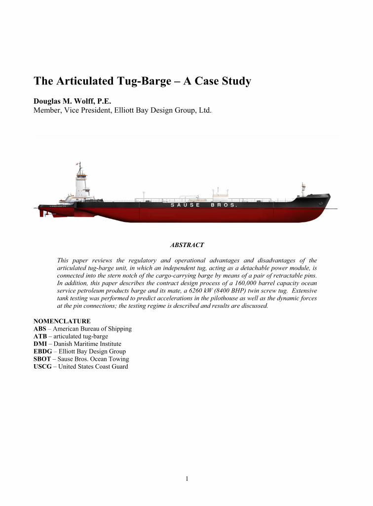
This paper reviews the regulatory and operational advantages and disadvantages of the articulated tug-barge unit, in which an independent tug, acting as a detachable power module, is connected into the stern notch of the cargo-carrying barge by means of a pair of retractable pins. In addition, this paper describes the contract design process of a 160,000 barrel capacity ocean service petroleum products barge and its mate, a 6260 kW (8400 BHP) twin screw tug. Extensive tank testing was performed to predict accelerations in the pilothouse as well as the dynamic forces at the pin connections; the testing regime is described and results are discussed.
NOMENCLATURE ABS – American Bureau of Shipping ATB – articulated tug-barge DMI – Danish Maritime Institute EBDG – Elliott Bay Design Group SBOT – Sause Bros. Ocean Towing USCG – United States Coast Guard
2
INTRODUCTION
At least 43 articulated tug-barge units are currently in service in the Western hemisphere, serving all three North American coasts as well as the Great Lakes, Hawaii and the Caribbean. Interest in ATBs is rapidly growing, due in large measure to regulatory influences and the expected growth in floating processing, storage and offloading facilities.
In late 1999, Sause Bros. Ocean Towing teamed with Elliott Bay Design Group to design an ATB for all-weather service on the west coast of the United States, a route which is well known for stormy winter weather conditions, few ports of refuge, and an unforgiving leeward shore.
Selection of the ATB configuration was driven by USCG regulatory considerations, while the size and functional arrangements were driven by the capabilities of the oil terminals to be served.
REGULATORY REGIME
USCG regulations dictate a higher standard of safety, and larger crew, for a tankship or cargo ship than for a tug towing an unmanned barge. Additionally, the USCG ruled in 1981 that an ATB would, for enforcement purposes, be considered separately as a tug and a barge. This statutory differential forms the basis for the prevalence of coastal transportation tugs and barges in the United States. A further benefit of the ATB concept is that, although tank ships and oil barges are required to be USCG-
inspected, a tug measuring less than 300 U.S. regulatory gross tons is an uninspected vessel.
Regulations pertaining to tank ships, tugs and oil barges are found in the Code of Federal Regulations (Titles 33 and 46), USCG Navigation and Vessel Inspection circulars, and the USCG Marine Safety Manual, as well as SOLAS, which is applied to vessels on international voyages. To enhance marketing and operational flexibility, SBOT made the decision early in the design process that the subject vessels would be designed and constructed in compliance with relevant SOLAS regulations.
ATB Advantages By far the largest advantage of the ATB as
compared with a U.S.-flag tank ship or cargo ship lies in the USCG manning regulations. Depending on the level of automation, the regulations mandate a ship crew size of between 15 and 24, whereas an ATB tug will require a crew of no more than seven. The cost savings resulting from this crew size differential has been the primary economic driver for the expansion of the ATB fleet.
A safety argument favoring the ATB (as compared to a ship) lies in the ability to disengage the tug and shift to a towing mode in the event of a major fire or collision. In addition, the tug can be used independently of the barge for oil boom deployment or other purposes.
Compared to a towed barge configuration, the ATB offers several significant advantages, including increased speed, reduced fuel consumption, ability to transit in higher sea states, access to the barge at all times, and elimination of the vulnerable tow wire
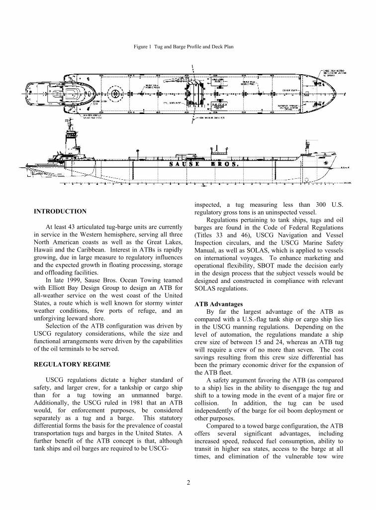
Figure 1 Tug and Barge Profile and Deck Plan
3
connections. Another benefit is that of reduced accelerations on the tug, resulting in greater crew comfort and reduced fatigue.
A scheduling advantage, particularly for short runs, lies in the ability for one tug to service two or more barges. An example of this would be the case wherein an empty barge is delivered to a terminal for loading, and a previously loaded barge is taken away immediately, avoiding down time for the tug and crew. This efficiency must be carefully balanced with the issue of crew rest, but can result in near-full utilization for the expensive propulsion unit.
Some study has also been given to the use of ATB units where the voyage includes both river and coastwise legs. A smaller, less powerful tug could be used for the river service segment, and a more powerful tug could take over for the coastwise segment. This scheme would require careful scheduling, but might create significant economic advantages on a heavily traveled route.
ATB Disadvantages Disadvantages of an ATB as compared with a ship
include speed, maneuverability, and the inherent "weak link" connecting the tug and barge.
Significant hydrodynamic inefficiencies are unavoidable when the tug operates in a notch. Severe discontinuities in hull shape at the notch introduce turbulence, resulting in increased resistance and reduced propeller efficiency. Additionally, the propeller diameter is limited by the light draft of the tug. These issues combine to reduce total hull and propulsive efficiency so that the ATB can be expected to sacrifice one or more knots at full speed.
ATB maneuverability may be marginally compromised because the beam of the tug limits the transverse distance between rudders. Rudders on a ship can be further apart transversely and so can provided greater turning moment, particularly when one engine is backing down. For this project, no
effort was made to document any differential in maneuverability.
Use of a connection system, no matter how reliable, will always introduce the risk of unintentional disconnection. Although a number of operators report no such events, others have experienced connector failure resulting in damage to both the tug and barge, and forcing a change to the towing mode. These events, however, have been very rare and have not slowed the pace of introduction of new ATB units.
Compared to a traditional towed barge configuration, ATB disadvantages include increased acquisition cost and reduced barge interchangeability.
CONCEPT DESIGN PROCESS
Certain fundamental requirements were established at the start of the design process – these requirements were the "drivers" in establishing length, beam and depth.
SBOT had determined a market requirement for a clean products transport with a capacity of about 160,000 barrels. Individual tank size was established at about 12,000 barrels, the typical size of the tanks at the terminals to be served.
Schedule reliability was deemed to be very important. To achieve this requirement, it was necessary that the ATB have the ability to at predictable speed in expected sea conditions, as well as possessing the ability to cross the notorious Columbia River bar in all but the most exceptional conditions. A comprehensive testing program, discussed below, was conducted to ensure that performance goals would be achieved.
The owner's construction philosophy is to specify heavier-than-required scantlings and to perform regular maintenance for longevity. This philosophy dictated that hull materials at the sheer strake, hull and forebody be increased above those required by the
American Bureau of Shipping. SBOT decided to class the vessel with ABS and to apply for the SafeHull designation. SafeHull is a global finite element analysis of all critical hull structure, with special emphasis on hull girder bending loads and cargo tank sloshing loads.
PERFORMANCE PREDICTION PROGRAM
To ensure safe and efficient performance when subjected to the weather conditions of the North American west coast, SBOT decided to invest in both computational fluid dynamics (CFD) analysis and a rigorous model testing regime. The goals of this prediction program were, in order of priority: • Accurately estimating the forces at the connection
pins • Determining accelerations at the upper pilothouse • Estimating speed in waves and still water • Optimizing bow shape for excellent seakeeping
and minimum resistance • Optimizing skegs for effectiveness and minimum
resistance • Optimizing barge aft hull form for minimum
resistance. Reliable program results are obviously dependent
on the quality of the program input, quality of the calculations, and the quality of testing models and
4
methods. Key among the various inputs are the data used to create the waves for the model testing.
Wind and Wave Data Wind and wave data used in determining the model
wave spectrum were collected by National Oceanic and Atmospheric Administration weather buoys moored off the U.S. west coast between 1983 and 1993. Data was recorded every ten minutes and then processed by NOAA to create climactic data summary tables and plots.
Throughout the selected geographic range, annual mean wind speed shows two peaks, averaging 14 knots (peaking at 16.6 knots) at 320° true and 12.5 knots (peaking at 15 knots) at 170° true.
The annual trend in significant wave heights showed the majority of waves were approximately two and a half meters. When the monthly trends were examined they nicely followed that of the wind trends with lower significant wave heights in the summer months of one and a half to two meters. The larger waves of the winter months ranged from two and a half to three meters in height.
Wave periods tended to be longer in the winter months than in the summer months. On an annual basis, the average wave periods ranged between six and eight seconds.
Analysis of the sea spectrum buoy data resulted in the following Ochi wave spectrum parameters: • Wind driven wave height: 2.70 m • Wind driven wave frequency: 8.4 seconds • Wind driven shape parameter: 3.0 • Swell driven wave height: 4.30 m • Swell driven wave frequency: 14.3 seconds • Swell driven shape parameter: 2.4
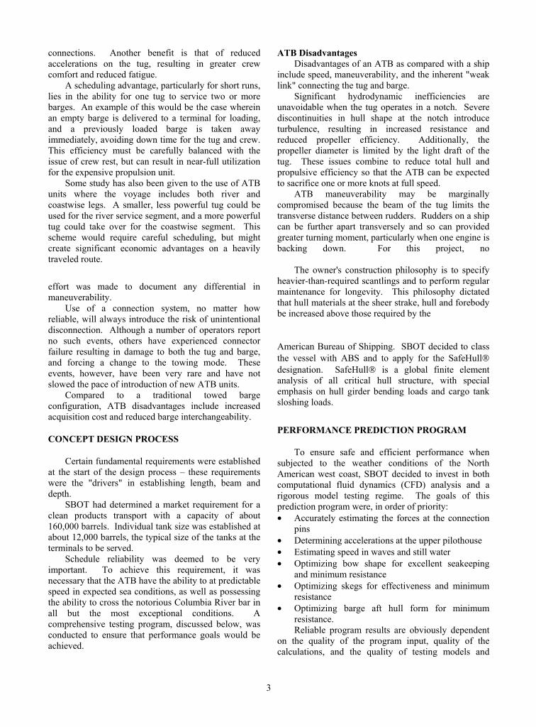
CFD Analysis DMI performed analysis for the tug and barge in
both light and loaded conditions. Water velocity distribution, wave patterns and tuft diagrams were created; see Figure 2 for a sample tuft diagram. Smooth water speeds were estimated at 13.90 knots and 12.90 knots, respectively. The following
recommendations arose from the CFD analysis: • Making the barge aft waterlines finer would reduce
a predicted wave trough aft. This recommendation was incorporated into the lines plan.
• Reducing the slope of the barge aft buttocks would reduce the likelihood of flow separation. This recommendation was also incorporated into the lines plan.
• Modifying the barge stem to a vertical profile would reduce wave-making resistance somewhat. This recommendation was not incorporated because of concerns that a vertical stem profile would have reduced seakeeping capability.
• Changing the angle of attack of the skegs would result in improved flow patterns and reduced resistance. This change was incorporated into the line plan.
Still Water Resistance Tests Using the lines plans as revised after inclusion of
CFD recommendations, Danish Maritime Institute fabricated wood models of the tug and barge at a scale of 23.45:1. The scale was selected to suit the model basin dimensions and to permit use of existing propellers for the tug. Propeller characteristics were as follows:
Diameter: 0.1559 m Pitch ratio: 0.7550 Length @ 0.7R: 0.0654 m Blade area ratio: 0.6320 4 blades, no rake. Barge appendages included the transverse bow
thruster tunnel and two skegs. Tug appendages included three rudders, two shaft struts and two propeller bossings. The tug model was self-propelled.
Paint streamline tests indicated that the tug lines were as efficient as could be expected, given the fact that the tug has bilge chines for simplicity of construction. Flow lines on the barge were very reasonable except that some separation was evident at the radiused intersection of the flat of bottom with the stern rake bottom slope. DMI recommendations to reduce the angle of the aft rake bottom slope were
Figure 2 Tuft diagram
5
0
500
1000
1500
2000
2500
3000
3500
7 8 9 10 11 12 13 14
Ship speed (knots)
P D (k
W)
0
50
100
150
200
250
300
350
Prop
elle
r rev
olut
ion
(RPM
)
Delivered Thrust, Light Draft Delivered Thrust, Loaded DraftPropeller RPM, Light Draft Propeller RPM, Loaded Draft
incorporated into the lines plan. Flow line results were also used to fine-tune the angle of attack of the skegs.
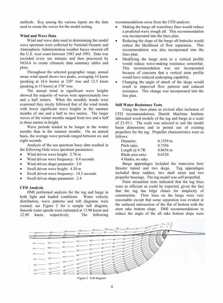
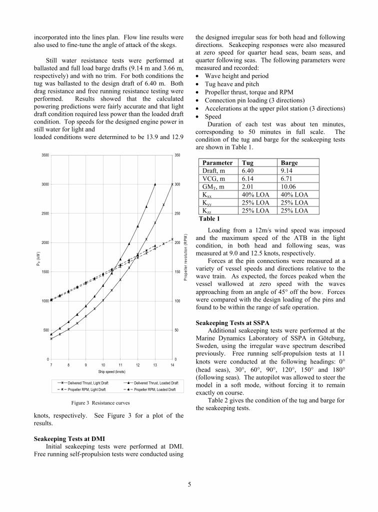
Still water resistance tests were performed at ballasted and full load barge drafts (9.14 m and 3.66 m, respectively) and with no trim. For both conditions the tug was ballasted to the design draft of 6.40 m. Both drag resistance and free running resistance testing were performed. Results showed that the calculated powering predictions were fairly accurate and that light draft condition required less power than the loaded draft condition. Top speeds for the designed engine power in still water for light and loaded conditions were determined to be 13.9 and 12.9
knots, respectively. See Figure 3 for a plot of the results.
Seakeeping Tests at DMI Initial seakeeping tests were performed at DMI.
Free running self-propulsion tests were conducted using
the designed irregular seas for both head and following directions. Seakeeping responses were also measured at zero speed for quarter head seas, beam seas, and quarter following seas. The following parameters were measured and recorded: • Wave height and period • Tug heave and pitch • Propeller thrust, torque and RPM • Connection pin loading (3 directions) • Accelerations at the upper pilot station (3 directions) • Speed
Duration of each test was about ten minutes, corresponding to 50 minutes in full scale. The condition of the tug and barge for the seakeeping tests are shown in Table 1.
Parameter Tug Barge Draft, m 6.40 9.14 VCG, m 6.14 6.71 GMT, m 2.01 10.06 Kxx 40% LOA 40% LOA Kyy 25% LOA 25% LOA Kzz 25% LOA 25% LOA
Table 1
Loading from a 12m/s wind speed was imposed and the maximum speed of the ATB in the light condition, in both head and following seas, was measured at 9.0 and 12.5 knots, respectively.
Forces at the pin connections were measured at a variety of vessel speeds and directions relative to the wave train. As expected, the forces peaked when the vessel wallowed at zero speed with the waves approaching from an angle of 45° off the bow. Forces were compared with the design loading of the pins and found to be within the range of safe operation.
Seakeeping Tests at SSPA Additional seakeeping tests were performed at the
Marine Dynamics Laboratory of SSPA in Göteburg, Sweden, using the irregular wave spectrum described previously. Free running self-propulsion tests at 11 knots were conducted at the following headings: 0° (head seas), 30°, 60°, 90°, 120°, 150° and 180° (following seas). The autopilot was allowed to steer the model in a soft mode, without forcing it to remain exactly on course.
Table 2 gives the condition of the tug and barge for the seakeeping tests.
Figure 3 Resistance curves
6
Parameter Symbol Tug Barge
Draft forward, m TF 6.40 9.14 Draft aft, m TA 6.40 9.14 Displacement, MT ∆ 1756 28102 Vertical center of gravity, m
VCG 6.14 6.71
Metacentric height, m
GMT 2.01 4.00
Roll radius of gyration, m
Ixx 5.59 9.51
Pitch radius of gyration, m
Iyy 10.29 40.75
Yaw radius of gyration, m
Izz 10.29 40.75
Table 2
Motions in the pilothouse were also measured and recorded at a variety of vessel speeds and directions (relative to the wave train). NORDFORSK establishes the following motion limits to ensure maximum crew effectiveness: • Vertical acceleration (RMS): 0.15 g • Lateral acceleration (RMS): 0.12 g • Roll (RMS) 4°
Measured values at the pilothouse fell below these limits with the exception of the zero speed condition in a beam seaway. It should be noted that bilge keels were not fitted on the model for any of the testing.
Maneuvering tests demonstrated excellent maneuverability at all tested speeds and relative directions, although a constant rudder angle of about 20° was required to maintain heading in a beam sea.
Survival State Seakeeping Tests at SSPA Survival state seakeeping tests were performed
primarily to measure the loads at the tug-barge pin connections and were based on the "hundred-year storm" with the following Ochi wave spectrum parameters: • Wind driven wave height: 6.34 m • Wind driven wave frequency: 8.4 seconds • Wind driven shape parameter: 3.0 • Swell driven wave height: 7.41 m • Swell driven wave frequency: 12.5 seconds • Swell driven shape parameter: 2.4
In comparing these values with those defining the normal sea state, one can see a significant increase in wave height. In practical terms, this spectrum indicates the expectation of encountering a 14 meter wave every 3½ hours.
Measured loads were considered when selecting the connection pin size.
CONNECTION SYSTEMS
The great majority of connection systems currently in service in North America were designed and manufactured either by Bludworth Cook or Intercontinental Manufacturing.
The Bludworth Cook system is based upon a single hinge point at the forward end of the notch. The tug is fitted with retractable skid pads at amidships port and starboard, and a hydraulically-actuated clamp at the stem. The tug enters the notch with one pad retracted (for side clearance) and advances until the clamp engages the hinge mechanism. Once the clamp is secured, the retracted pad is extended. The two pads are lubricated and allow the tug to pitch about the stem hinge in an arc against the notch side plating. The tug is coupled in roll and heave to the barge.
Similarly, the Intercon system allows the tug to pitch independently of the barge, but couples the ATB in heave and roll. The tug is fitted with retractable, hydraulically-actuated pins port and starboard, forward of amidships. The pins are retracted as the tug enters the notch, and are extended once aligned with ladder castings that are built into the notch sides.
SBOT performed their own research on connection systems and selected the Intercon system for this project. The selected pin diameter was 1626mm (64"), one size larger than indicated by the forces determined from the seakeeping tests, but in keeping with SBOT construction philosophy.
BARGE CHARACTERISTICS
Length, molded 162.96 m Length, design waterline 159.48 m Beam, molded 23.77 m Depth, molded amidships 13.11 m Design draft 9.14 m Cargo capacity 161,940 bbl Ballast capacity 70,500 bbl Potable water capacity 11.0 m3 Fuel oil capacity 60.1 m3
Barge Arrangements One of the first required decisions regarding the
arrangements of the barge was whether to have a flush deck or a raised trunk. The raised trunk configuration results in less total weight of steel. The Owner, however, favored the flush deck configuration based on simplified maintenance and enhanced crew safety while working near the vessel side. Accordingly, the flush deck design was adopted, see Figure 1.
Pump engine/generator houses are located forward of the amidships manifolds and are set well off of vessel centerline for visibility of the full length of the deck from the tug pilothouse.

7
The foc'sle provides space for the cargo control room, workshop, day room, spill response equipment room, potable water tank, and chain lockers. The bow thruster room below the foc'sle is accessed by an inclined ladder and houses the thruster, thruster engine, air compressor, oily water pump, bilge pump and bilge manifold. Arrangements are provided in Figure 4.
Figure 4 Bow thruster machinery
Tank Configuration Seven pairs of tanks form the cargo block. At 99%
full, ten tanks have an approximate capacity of 11,850 barrels each and four have an approximate capacity of 10,500 barrels each. Tank capacities were standardized to suit the shoreside tank capacities of the terminal facilities. In accordance with SOLAS regulations, wing and double bottom tanks are fitted, and can be used for ballast. An additional pair of ballast tanks for trim control is located in the stern rake aft of the cargo block. Total ballast capacity is 70,500 barrels, served by two Byron Jackson 2-stage deep well pumps, each with a capacity of 5000 barrels per hour at 21.3 m (70') head.
A diesel oil storage tank is located in the cofferdam space between the cargo block and the bow thruster machinery space. The forward part of the port side pump engine house contains two slop (stripping) tanks with 26.5 cubic meter (7000 gallon) capacity each, a fuel oil day tank, a dirty oil tank and an hydraulic oil storage tank.
Structural Features The entire barge is constructed of mild steel.
Scantlings were originally determined from the ABS Rules for Barges; however, the Owner elected, late in the design, to have the barge SafeHull certified, thus applying ABS tank ship rules. The effect of the application of the ship rules was an increase in scantlings at the transverse bulkheads and stools. The final midship section is shown in Figure 5 and includes some specific scantling increases that reflect SBOT preferences.
Figure 5 Midship section

8
Cargo System The four main cargo pumps are Byron Jackson 4-
stage, diesel engine-driven, rated 5000 barrels per hour at 114 meter head (3500 GPM at 375'). These pumps are located in the #4 cargo tanks. The Detroit Diesel Series 60 engines (rated 395 HP at 1800 RPM) that power the pumps are installed in the pump engine houses port and starboard. Pump engines are compressed air start and air cooled.
Stripping pumps are located on the main deck forward of the port side pump engine house and are powered by hydraulic motors.
The manifold, shown in Figure 6, is located amidships and consists of four headers, each fitted with 10" discharge valves port and starboard. Additionally, each header pipe is fitted with a 10" hose connection at the hose manifold aft at the aft side of the load/discharge manifold.
Cargo stripping and vapor recovery systems are installed; discharge headers are provided at the manifold port and starboard.
Machinery Installation A diesel engine-driven transverse tunnel thruster is
located forward. Based on windage studies, the thruster is rated at 559 kW (750 horsepower) to provide control of the forward end of the barge during docking maneuvers.
Deck machinery consists of two fixed boom cranes for hose handling, two windlasses with single mooring drums, two double drum mooring winches, and two single drum mooring winches. All deck machinery is powered by a common medium pressure hydraulic system An electro-hydraulic power unit as well as engine-driven hydraulic pumps are located in the port side pump engine house.
Air compressors are located in the bow thruster room and in each pump engine house. Compressed air is used for starting the thruster engine and cargo pump engines (generator engines are electric start), for control air, and for general services.
Electrical Installation Two 95 kW diesel generator sets provide ample
power for barge electrical requirements. The rating of the generators was selected to avoid the USCG-inspection requirements for generator sets rated at 100 kW or more. Generators are located in the starboard pump engine house.
A shore power connection is provided, but the Owner chose not to provide an umbilical connection between the tug and barge.
TUG CHARACTERISTICS
Length, molded 41.27 m Length, design waterline 41.10 m Beam, molded 14.02 m Depth, molded amidships 6.48 m Design draft 6.40 m Propulsion power 6260 kW Potable water capacity 68.1 m3 Fuel oil capacity 870.5 m3
Arrangements The ATB configuration imposes specific and
challenging tug design requirements. Most obviously, a pilothouse must be located high enough so as to provide visibility when the barge is light and the tug has a full fuel load. Equally obvious is the need for the tug to fit into the notch. Not so apparent are the tight tolerances required to guarantee proper operation of the connection system, coupled with the need for adequate clearances to prevent binding when the tug pitches within the notch. Because of these issues, fendering selection must be made early in the design process. Fendering details are shown in Figure 7.
Below the main deck, the tug is designed to take advantage of the archaic (and nonsensical) United States admeasurement rules. Careful placement of
Figure 6 Cargo manifold

9
Figure 7 Elevation of tug fendering
ballast tanks and transverse non-tight bulkheads results in gross tonnage less than 200, the point at which additional manning requirements significantly increase operational costs.
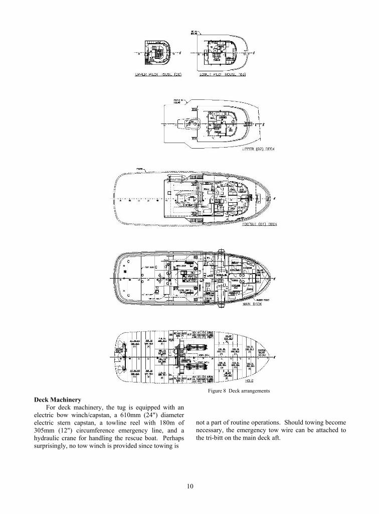
On the main deck, arrangements must be designed around the coupling rams and machinery, which occupy prime real estate forward of amidships. Arrangements are shown in Figure 8.
Two complete pilothouses are provided; see Figure 9. It is expected that the lower pilothouse (at the 03 level) will be used whenever possible for reduced motions. The upper pilothouse (at the 06 level) will be used only when the barge is light or when improved visibility is required.
Structural Features Because the vessel will be classed, the structure
and machinery were designed in compliance with the ABS rules for small ships.
Several structural features are noteworthy. Most apparent is the forest of transverse bulkheads below the main deck. These bulkheads serve only to reduce the admeasured regulatory tonnage and would appear only on a U.S flag vessel. Elimination of these redundant bulkheads would reduce construction cost, lightship weight and maintenance cost.
SOLAS regulations mandate a full double bottom in the engine room. For the tug, however, a waiver from this requirement was sought. The basis for appeal was that a double bottom under the main engines would raise the main engines, also raising their exhausts and consequently the main deck, increasing hull depth and raising the center of gravity, reducing stability. The
USCG approved the waiver request, but stipulated that a double bottom must be installed on vessel centerline inboard of the main engine foundations, and that the shell plating thickness outboard of the bottom must be increased. These requirements were incorporated into the design.
The Intercon coupler unit is furnished within a structural box assembly that includes the transverse bulkheads immediately forward and aft (located at frames 17 and 23) as well as the main deck below, the 01 Deck above, and the side shell structure. This entire assembly is fabricated to match the lofted lines plan and will be dropped in place as a unit before the deckhouse and tower are set on the vessel.
To reduce both topside weight and maintenance, the tower structure above the 03 level is aluminum and is welded to the steel structure below using explosion-bonded bimetallic strips.
Figure 9 Tug outboard profile
10
Deck Machinery For deck machinery, the tug is equipped with an
electric bow winch/capstan, a 610mm (24") diameter electric stern capstan, a towline reel with 180m of 305mm (12") circumference emergency line, and a hydraulic crane for handling the rescue boat. Perhaps surprisingly, no tow winch is provided since towing is
Figure 8 Deck arrangements
not a part of routine operations. Should towing become necessary, the emergency tow wire can be attached to the tri-bitt on the main deck aft.
11
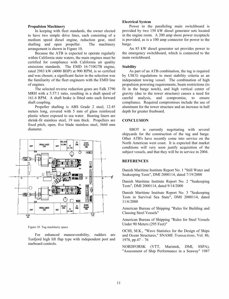
Propulsion Machinery In keeping with fleet standards, the owner elected
to have two simple drive lines, each consisting of a medium speed diesel engine, reduction gear, steel shafting and open propeller. The machinery arrangement is shown in Figure 10.
Because the ATB is expected to operate regularly within California state waters, the main engines must be certified for compliance with California air quality emissions standards. The EMD 16-710G7B engine, rated 2983 kW (4000 BHP) at 900 RPM, is so certified and was chosen; a significant factor in the selection was the familiarity of the fleet engineers with the EMD line of engines.
The selected reverse reduction gears are Falk 3790 MRH with a 5.57:1 ratio, resulting in a shaft speed of 161.6 RPM. A shaft brake is fitted onto each forward shaft coupling.
Propeller shafting is ABS Grade 2 steel, 12.45 meters long, covered with 5 mm of glass reinforced plastic where exposed to sea water. Bearing liners are shrink-fit stainless steel, 19 mm thick. Propellers are fixed pitch, open, five blade stainless steel, 3660 mm diameter.
Figure 10 Tug machinery space
For enhanced maneuverability, rudders are Tenfjord high lift flap type with independent port and starboard controls.
Electrical System Power to the paralleling main switchboard is
provided by two 150 kW diesel generator sets located in the engine room. A 200 amp shore power receptacle is provided, as is a 100 amp connector for power to the barge.
An 85 kW diesel generator set provides power to the emergency switchboard, which is connected to the main switchboard.
Stability As part of an ATB combination, the tug is required
by USCG regulations to meet stability criteria as an independent towing vessel. The combination of high propulsion powering requirements, beam restrictions (to fit in the barge notch), and high vertical center of gravity (due to the tower structure) causes a need for careful analysis, and compromise, to ensure compliance. Required compromises include the use of aluminum for the tower structure and an increase in hull depth for greater freeboard.
CONCLUSION
SBOT is currently negotiating with several shipyards for the construction of the tug and barge. Other ATB's have recently come into service on the North American west coast. It is expected that market conditions will very soon justify acquisition of the subject vessels, and that they will be in service in 2004.
REFERENCES
Danish Maritime Institute Report No. 1 "Still Water and Seakeeping Tests", DMI 2000114, dated 7/19/2000
Danish Maritime Institute Report No. 2 "Seakeeping Tests", DMI 2000114, dated 9/14/2000
Danish Maritime Institute Report No. 3 "Seakeeping Tests in Survival Sea State", DMI 2000114, dated 11/6/2000
American Bureau of Shipping "Rules for Building and Classing Steel Vessels"
American Bureau of Shipping "Rules for Steel Vessels Under 90 Meters (295 Feet)"
OCHI, M.K., "Wave Statistics for the Design of Ships and Ocean Structures," SNAME Transactions, Vol. 86, 1978, pp.47 – 76
NORDFORSK (VTT, Marintek, DMI, SSPA), "Assessment of Ship Performance in a Seaway" 1987