5200,20 and distribution statement a - dtic.mil · distribution statement a ... test andf...
TRANSCRIPT
THIS REPORT HAS BEEN DELIMITED
AND CLEARED FOR PUBLIC RELEASE
UNDER DOD DIRECTIVE 5200,20 AND
NO RESTRICTIONS ARE IMPOSED UPON
ITS USE AND DISCLOSURE,
DISTRIBUTION STATEMENT A
APPROVED FOR PUBLIC RELEASE;
DISTRIBUTION UNLIMITED,

,-VLiJT OF .
NAVAL SHIP RESEARCH AND DEVELOPMENT CENTER4 Bethes da, Maryland 20034
AN
4C SUBMARINE SYSTEM FOR LOGISTICS
0 AND REPLENISHMENT
S by
Stephen T. W. Liang
Q~I Distribution limited to U. S. Government agenciesonly; Test andf Evaluation Information, February 1975.Other requests for this document must be referred toIT-
iiO Naval Ship Research and Development Center, Code/
SYSTEMS DEVELOPMENT DEPARTMENT EII RESEARCH AND DEVELOPMENT REPORTI
1 February 1975 Report 4504

11 e NAvl Sh.p et-earch and Development Center is a U. S. Navy center tot laboratory
e[fort directed at achieving improved sea and air vehicles. It was formed in March l"t?7 bym ergian the David Taylor Mode! Basin at Cairderock, Maryland with the Marine F, rar,
1Laboratory at Annapoh!,, Maryland-
Nav r Ship Research and Development Center
Bethesda, Md. 20084
MAJOR NSRDC ORGANIZATIONAL COMPONENTS
r4SRDC
I COMMANDER 0I 00
*REPORT ORIGINATOR TECHNICAL DIRECTOR0 1
OFFICER.IN-CHARGE OFFICER-IN-CHARGECARDEROCK 05ANNAPOLIS 0
*SYSTEMSDEVELOPMENTDEPARTMENT
SROAAVIATION ANDSHIP PERFORMANCE SURFACE EFFECTS
DEPARTMENT 15 DEPARTMENT 16
COMPUTATION
DERTRENT AND MATHEMATICSDEPARTMENT 1 DEPARTMENT 18
[ PROPULSION ANDShIP ACOUSTICS AUXILIARY SYSTEMSDEPAPTMENT 19
DEPARTMENT 27
MATERIALS CENTRAL
DEPARTMENT IINSTRUMENTATIONDPR N 28, -DEPARTMENT 29

UNCLASSIFIEDSECURITY CLASSIFICATION OF THIS PAGE (i7hen Data Entered)
REPOT DOUPANTATON AGE EADINSTRUCTIONS
REPOT DCUMNTATON AGEBEFORE COMPLEIr~ FORM
REPORT UM13ER2. GOVT ACCESSION NO. 3. RECIPIENT'S CATALOG NUMBER
4. 4504 1_______________
4TITLE (and Subtitle) 5. TYPE OF REPORT A PERIOD COVERED
SUBMARINE SYSTEM FOR LOGISTICS _ _ _ _ _ _ _ _ _
AND REPLENISHMENT 6. PERFORMING ORG. REPORT NUMBER
7. Au~CR~e)8. CONTRACT OR GRANT NUMBER(#)
Stephi i T. W. Liang
9. PERFORMING ORGANIZATION NAME AND ADDRESS 10. PROGRAM ELEMENT. PROJ SCT. TASKAREA & WORK UNIT NUMBERS
Naval Ship Research and Development Center Task Area ZF61412001Bethesda, Maryland 20084 WVork Unit 1-1100-001
II. CONTROLLING OFFICC NAME AND ADDRESS 7 12. REPORT DATE
Naval Ship Research and Development Center February 1975Bethesda, Maryland 20084 13. NU1ER OF PAGES
14. MONITORING AGENCY NAME &ADDRESS(If different !rom Controlling Oftice) 15. SECURITy CLASS. fol this report) IUNCLASSIFIED
I~se DECL ASSI FicATi-oN/ DOWN GRADINGSCHEDULE
16. DISTRIUTION STATEMENT (of this Report) IDistribution limited to U. S. Government agencies only, Test and Evaluation Informiation.
February 1975. Other requests for this document must be referred to Naval Ship Research andDevelopment Center. Code I1.
17. DISTRIBUTION STATEMENT (of the ebetreet entered In Block 20. If different from Report)
18 SUPPLEMENTARY NOTES
19. KEY WORDS (Contit.9~ on reverse old* It necessary end Identity by block number)
20. ABSTRACT (Continue on reverse side If necoeeey and identify by block number)
This report examines the technical feasibility of submarine alternatives to surface-borne cargo transport. Beginning with gross statements of potential missions and missionIrequirements, the study derives submarine concepts of transporting military loads which
are assumned packaged in standard commercial containers. Submarines of conventionaland tug-barge configurations are examined and estimates made of speed-powerI
(Continued on reverse side)
DD I JAN 73 1473 EDITION OF I NOV 65 IS OBSOLETE UCAS lESIN 0102-014- 6601 1 NLSSFE
SECURITY CLASSIFICATION Of THIS PAGE (When Dots Entered)I

UNCLASSIFIED.LLUtOTY CLASSIFICATION OF THIS PAGE(Whe'i Data Entered)
(Block 20 continued)
performance near the surface, dynamic stability and control, surfaced motions andseaway loads. Several cross-sectional hull and structural geometries are examined forstructural adequacy and weight. Possible weight allocations for a submarine cargoship are presented.
Results of this preliminary feasibility investigation indicate that the concept ofa cargo-carrying submarine may be technically feasible. It is found, however, thatthe transport efficiency of the submarine container cargo ship is significantly lowerthan that of a surface ship, and that unless other factors, such as attrition are con-
sidered, there is little incentive to consider submarine cargo transport.
i1
aIir
I '.
UNCLASSIFIEDSECURITY CLASSIFICATION OF THIS PAGE(When Data Entered)
TABLE OF CONTENTST
Page
ABSTRACT. .. .... ...... ..... ...... ......
ADMINJSTRATIVE INFORMATION .. .. ...... ..... ............... I
INTRODUCTION. .. ... ...... ..... ...... .....
HISTORY AND BACKGROUND. .. .. ...... ...... ...... 2 1GENERAL CARGO SUBMARINE. .. ..... ..... ........ 2SUBMARINE TANKER .. .. .. ...... ...... ........ 2
TOWED SUBMARINE BARGE....... ..... . . .... .. .. .. .. . .2SUBMARINE ORE CARRIER. .. .. ...... ...... ...... 3SUBMARINE CONTAINER SHIP. .. .. ..... ..... ....... 3 1
MISSION REQUIREMENTS .. .. .... ..... ...... ...... 4
GENERAL .. .. ... ...... ...... ..... ....... 4CARGO LOAD. .. .. ...... ......... .... ...... 4
SHIP SYSTEM CONCEPTS. .. .... ...... ..... ....... 6SHIP CONFIGURATIONS .. .. .. ...... ......... ..... 6SPEED, POWER, AND SUBMERGENCE .. .. .... ..... ...... 7
OTHER HYDRODYNAMIC ANALYSES .. .. .... ..... ....... 8PHYSICAL CHARACTERISTICS. .. .. ...... ..... ...... 9SUBMERGED DYNAMIC STABILITY .. .. ... ...... ....... 9TURNING .. .. .... ...... ..... ...... ...... 10SURFACED MOTIONS. .. .. ..... ...... ..... .... 10SEA LOADS .. .. .... ...... ...... ..... .... 12
STRUCTURAL FEASIBILITY .. .. .... ...... ..... .... 12PRESSURE HULL ARRANGEMENT .. .. ..... ...... .... 12STRENGTH ANALYSIS. .. .... ...... ...... ...... 12
DESIGN EVALUATION .. .. ...... ...... ... ... ....
CONCLUSIONS .. .. ... ...... ...... ..... ...... 16
ACKNOWLEDGMEN-.TS. .. .. .... ...... ...... ...... 17
REFERENCES .. .. ..... ...... ...... ..... ... 45
LIST OF FIGURES
I - Icebreaker Towing Barge at Controlled Depth under Ice Field. .. . .... 18
2 - Model of Submarine Ore Carrier .. .. ..... ...... .... 19

Page
3 - Submarine Logistic System ... ................ .... 21
4 - Modular Submarine ........ ....................... ... 22
5 - Submarine Tug-Barge System.. ....... ................... 23
6 - General Arrangement of Tug-Barge TB-I. ..... ............... ... 24
7 - General Arrangement of Tug-Barge TB-3 ..... ............... ... 24
8 - Speed-Power Curve of the Submarine Tug-Barge TB-I. ............. ... 25
9 - Speed-Power Curve of the Submarine Tug-Barge TB-3 ..... .......... 26
10 - Body Plan and Profile of Submarine Tug-Barge TB-I .......... ..... 27
I I - Estimated Weight Curve for the Submarine Tug-BargeSystem, TB-I. ......... .......................... ... 27
12 - Appendages for TB-I Barge ....... .................... ... 28
13 - Appendages for TB-I Power Tug ........ .................. 28
• 14 - Control Characteristics for Submarine Tug-Barge TB-I ......... ..... 29
15 - Maximum Values of Transfer Functions for Heave Motionsfor 0 and 5 Knots ........ ........................ ... 29
16 - Maximum Values of Transfer Functions for Sway Motionsfor 0 and 5 Knots ........ ........................ ... 30
17 - Maximum Values of Transfer Functions for Pitch Motionsfor 0 and 5 Knots ........ ........................ ... 30
18 - Transfer Functions for Roll Motions versus Wavelengthto Shiplength ..... ..... .......................... 31
19 - Transfer Functions for Longitudinal Distribution of WaveInduced Sea Load ........ ........................ ... 32
20 - Pressure Hull Cross-Section Configurations .... .............. ... 33
21 - Circumferential Bending Moments in Pressure Hull ofTB-1 and TB-2 ........ ......................... .... 34
22 - Circumferential Bending Moments in Pressure Hull of TB-3 ........ ... 34
23 - Five Tentative Hull Designs ....... .................... ... 35
24 - Location of Permanent Ballast in TB-I and TB-2 ... ........... ... 36
iv

LIST OF TABLES
Page
I - Principal Characteristics for Proposed Submarine Tankers .. ........ .. 37
a 2 - Missions for Logistics and Replenishment ..... .............. ... 38
3 - Loading Specifications for Standard Demountable CargoContainers ..... ...... ........................... 38
4 - Princioal Characteristics of Submarine Tug-Barge System .... ........ 39
5 - General Relationships of Speed, Power, and Submergence ... ........ 39
6 - Geometric Properties and Weight Distribution Characteristics ......... ... 40
7- Characteristics of Appendages for Submarine Tug-Barge TB-I ...... 40
8 - Index of Stability of Submarine Tug-Barge TB-I. ..... ............ 41
9 - Maximum Values of Transfer Functions for Dynamic SeaLoads for Submarine Tug-Barge TB-I .... .... ................ 41
10 - Geometric Properties of Five Hull Structure Designs ..... .......... 42
I I - Structural Characteristics of Pressure Hull Design ... ........... ... 43
12 - Weights of Pressure Hulls ....... ... ................... 44
13 - Weight Estimate for TB-I ................... ....... .... 45
vI
VN
_ _ _ _ _ _ _,!A
* L
I:
Ipa A
0
0U
C)
'4 C)
0U-
LiJin
iN. .-
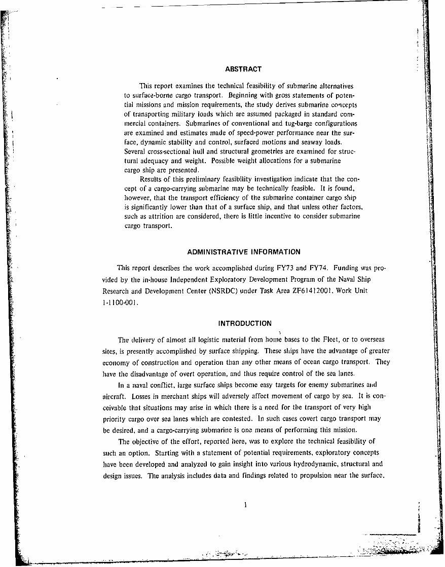
ABSTRACT
This report examines the technical feasibility of submarine alternativesto surface-borne cargo transport. Beginning with gross statements of poten-tial missions and mission requirements, the study derives submarine conceptsof transporting military loads which are assumed packaged in standard com-mercial containers. Submarines of conventional and tug-barge configurationsare examined and estimates made of speed-power performance near the sur-face, dynamic stability and control, surfaced motions and seaway loads.Several cross-sectional hull and structural geometries are examined for struc-tural adequacy and weight. Possible weight allocations for a submarinecargo ship are presented.
Results of this preliminary feasibility investigation indicate that the con-cept of a cargo-carrying submarine may be technically feasible. It is found,however, that the transport efficiency of the submarine container cargo ship
is significantly lower than that of a surface ship, and that unless other factors,such as attrition are considered, there is little incentive to consider submarinecargo transport.
ADMINISTRATIVE INFORMATION
This report describes the work accomplished during FY73 and FY74. Funding was pro-
vided by the in-house Independent Exploratory Development Program of the Naval Ship
Research and Development Center (NSRDC) under Task Area ZF61412001, Work Unit
1-1100-001.
INTRODUCTION
The delivery of almost all logistic material from home bases to the Fleet, or to overseas
sites, is presently accomplished by surface shipping. These ships have the advantage of greater
economy of construction and operation than any other means of ocean cargo transport. They Ihave the disadvantage of overt operation, and thus require control of the sea lanes.
In a naval conflict, large surface ships become easy targets for enemy submarines and
aircraft. Losses in merchant ships will adversely affect movement of cargo by sea. It is con-ceivable that situations may arise in which there is a need for the transport of very highpriority cargo over sea lanes which are contested. In such cases covert cargo transport may
be desired, and a cargo-carrying submarine is one means of performing this mission.
The objective of the effort, reported here, was to explore the technical feasibility of
such an option. Starting with a statement of potential requirements, exploratory concepts
have been developed and analyzed to gain insight into various hydrodynamic, structural and
design issues. The analysis includes data and findings related to propulsion near the surface,
stability and control, seaway loads when surfaced, structural concepts, structural strength and
weight. Conclusions relative to major findings are inclded.
HISTORY AND BACKGROUND
GENERAL CARGO SUBMARINE
The concept of a logistic, cargo-carrying submarine is not new. In World War I, the
German submarine freighter DEUTSCHLAND broke through the British sea blockade with a
cargo of dyes, precious stone and mail, and proceeded to Baltimore, Maryland, U. S. A. Shereturned safely to Bremen, Germany, exactly three weeks after her departure from the United
States bringing a return cargo of zinc, silver, copper and nickel. Both cargoes were composed
of obviously high-priority items.
SUBMARINE TANKER
With the successful development of nuclear propulsion after World War II it became
possible to consider submarines as noncombatant transport vehicles. Operating independently
of sea states and weather conditions, and not limited by ice conditions, submarine cargocarriers could maintain year-round operations in areas presenting hazards to surface ships. In
the past decade, many submarinc tankers have been proposed by the marine industry;'' 2 the
characteristics of some of these are listed in Table 1.3
At present, a vigorous program is being pursued by the Maritime Administration to studythe use of nuclear-powered submarine tankers to transport crude oil from the Alaskan oil
fields to either the East Coast of the United States or European ports. It has been proposed
that submarine tankers traverse under the polar ice cap and thus utilize a direct path andwith no need for icebreakers.
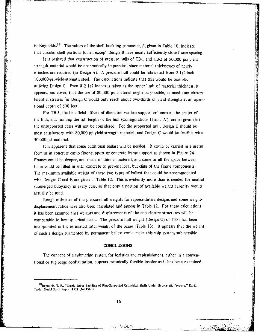
TOWED SUBMARINE BARGE
Another concept of shipping liquid cargo is that of using an icebreaker towing a sub-marine barge at a controlled depth below an icefield. According to Continental Oil Company,
this system has been shown to be technically feasible and also economically competitive with
other proposed systems for Arctic transportation. A design for a 250,000-deadweight (dwt)
Russo, V. L et al., "Submarine Tankers," SNAME Transactions, Vol. 68 (1960). A complete listing of referencesis given on page 45.
2Todd, F. It., "Submarine Cargo Ships and Tankers," Ship Division, National Physical Laboratory, Great Britain (Jan1961).
3.Is There a Future for the Giant Submarine Oil Tanker?" The Naval Architect. Journal of the Institute of NavalArchitecture, England (O,.t 1971).
2
' IL
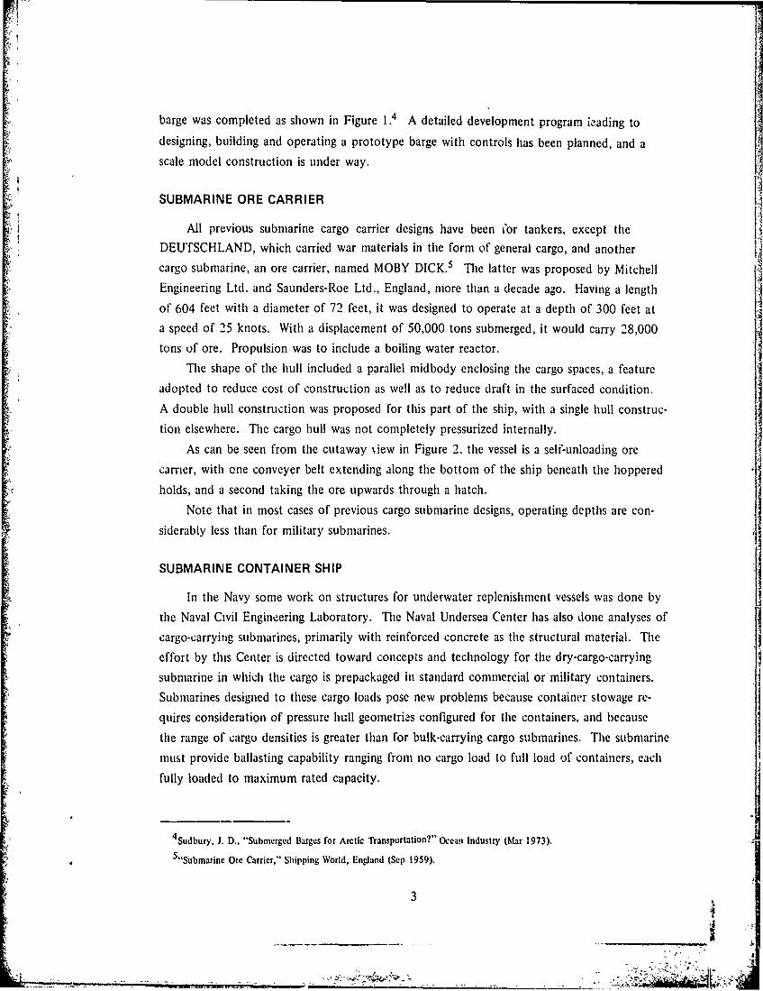
barge was completed as shown in Figure 1.4 A detailed development program ieading to
designing, building and operating a prototype barge with controls has been planned, and a
scale model construction is under way.
SUBMARINE ORE CARRIER
All previous submarine cargo carrier designs have been or tankers, except the
DEUTSCHLAND, which carried war materials in the form of general cargo, and another
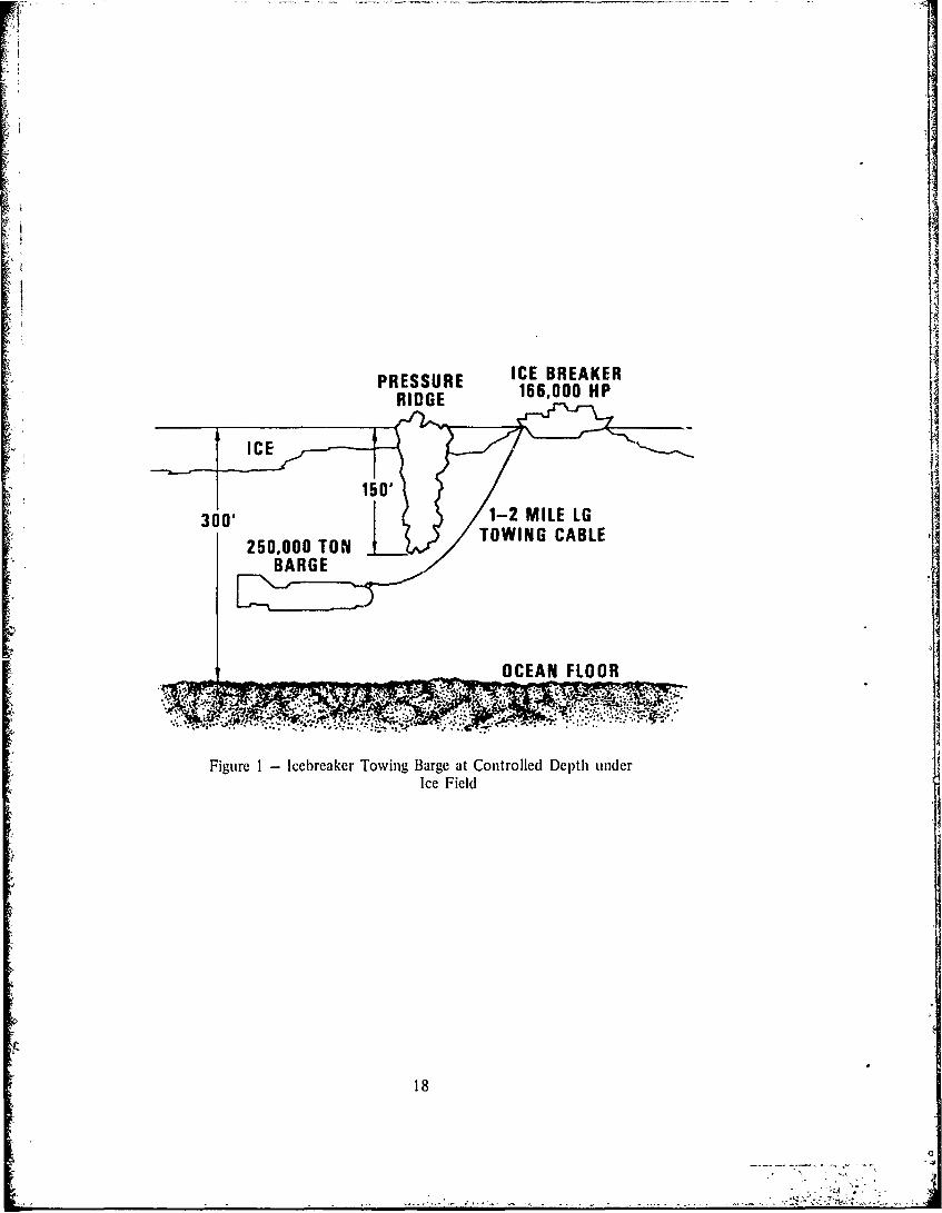
cargo submarine, an ore carrier, named MOBY DICK.5 The latter was proposed by Mitchell
Engineering Ltd. and Saunders-Roe Ltd., England, more than a decade ago. Having a length
of 604 feet with a diameter of 72 feet, it was designed to operate at a depth of 300 feet ata speed of 25 knots. With a displacement of 50,000 tons submerged, it would carry 28,000
tons of ore. Propulsion was to include a boiling water reactor.
The shape of the hull included a parallel midbody enclosing the cargo spaces, a feature
adopted to reduce cost of construction as well as to reduce draft in the surfaced condition.
A double hull construction was proposed for this part of the ship, with a single hull construc-
tion elsewhere. The cargo hull was not completely pressurized internally.
As can be seen from the cutaway Niew in Figure 2, the vessel is a self-unloading ore
carrier, with one conveyer belt extending along the bottom of the ship beneath the hoppered
holds, and a second taking the ore upwards through a hatch.
Note that in most cases of previous cargo submarine designs, operating depths are con-
siderably less than for military submarines.
SUBMARINE CONTAINER SHIP
In the Navy some work on structures for underwater replenishment vessels was done by
the Naval Civil Engineering Laboratory. The Naval Undersea Center has also done analyses of
cargo-carrying submarines, primarily with reinforced concrete as the structural material. The
effort by this Center is directed toward concepts and technology for the dry-cargo-carrying
submarine in which the cargo is prepackaged in standard commercial or military containers.
Submarines designed to these cargo loads pose new problems because container stowage re-
quires consideration of pressure hull geometries configured for the containers, and because
the range of cargo densities is greater than for bulk-carrying cargo submarines. The submarinemust provide ballasting capability ranging from no cargo load to full load of containers, each
fully loaded to maximum rated capacity.
4 Sudbury, J. D.. "Submerged Barges for Arctic Transportation?" Ocean Industry (Mar 1973).5 "Submarine Ore Carrier," Shipping World, England (Sep 1959).
3 N
,

MISSION REQUIREMENTS
GENERAL
As this effort was intended to examine broad issues of technical feasibility, there was
little need to firmly establish specific requirements for the cargo submarine. Instead postulated
missions and general requirements previously identified were accepted and used as a basis for
technical explorations herein. Missions for logistics and replenishment operations are listed in
Table 2.6
CARGO LOAD
In recent years, the use of standardized containers has come into practice for most dry
cargo shipment. In the past decade, the rate of growth of container ships has been much
greater than that of tankers or other cargo ships. As the record shows, 7 in January 1973, the
United States leads the world in container ships, with 31 percent of the total dead-weight
tonnage of the world fleet.
The containerized shipping of cargo has many advantages over the conventional storage
system: increased efficiency and lower transportation costs, such as handling (including
stevedoring); simplified inventory and delivery; and reduced costs in breakage, pilferage, and
insurance. Because of the economic attractiveness, the popularity of such a mode of trans-
portation will probably continue to grow for some time to come. In view of this situation,
it is likely that the naval supplies will be carried wholly or in part by containers, and that
new systems will be required for the transport and handling of containers. Cargo containers
are designed to meet the requirements of the American Society of Mechanical Engineers,
USA Standard Specifications for Cargo Containers (USASI MH5.1 - 1965). The length of
containers may vary from 20 to 40 feet, with end dimensions of 8 x 8 feet. Permissible con-
tainer loadings are shown in Table 3.8 The 20- by 8- by 8-foot container has been assumed
as standard for this study.
In practice the average loaded container weight will be less than the 20 long tons for
the 20-foot container shown in Table 3. A conventional surface container ship, operating on
a trade route, will trapsport empty containers along with loaded ones. Of the loaded con-
tainers there will be a laige distribution of weights caused by large variations in cargo density,
6 "Summary of Logistic and Replenishment Submarines," Southwest Research Institute, prepared for the Office of NavalResearch (Jan 1971).
7"Maritime Reporter and Engineering News," Ma,:itime Activity Reports. Inc. (Nov 1973).8USA Standard Specifications for Cargo C.ontainers (USASI MI15.I), ASME (1965).
4
and by incompletely stuffed containers. In establishing a cargo load for commercial (non-
military) design, an average 20-foot container is expected to weigh I I -15 long tons. Militaryloads are expected to be greater.
Knowledge of the cargo characteristics is, of course, important in the case of surface
containership design. Cargo weight will affect the form and dimensions of the ship, as well
as powering and range. When the design is established, however, the surface ship offers con-siderable latitude in accommodating to both the numbers and weights of containers carried.
This is not the case for the submarine container-carrying ship.
In a submarine container transport all containers are carried within the pressure hull, and
the pressure hull envelope prescribes the maximum number of containers to be carried. The
watertight envelope of the submarine establishes the submerged displacement, and to achieve
submergence, fully loaded weight must equal submerged displacement. The sum of all variable
weights, i.e., the difference between submerged displacement and fixed weight must be con-
stant to meet the condition of neutral submerged buoyancy. Variable weights include cargo
load, consumables and seawater ballast. Weight variations in cargo and consumables must becompensated by equal changes in ballast. As the cargo load can vary from zero to maximum
capacity, the demands upon variable ballast are potentially great.
For purposes of this study the author has elected not to provide variable ballast tankage
for the no-load case. it has been assumed that entire cargo compartments can be flooded to
achieve the required ship weight and static stability. Instead, average cargo weight is assumed
to fluctuate over a much narrower region, and variable ballast capacity is provided to accom-
modate this smaller fluctuation. For purposes of examining exploratory designs, military
cargo containers have been assumed to weigh between 15 and 20 long tons.
The depth of the ship determines the number of tiers of containers that can be accom-
modated in the hold. Current container design practices are based on the assumption that
they are stacked to a maximum of six high. 9 In a submarine, since the containers cannot
be stacked on deck as on a surface ship, an increase in this capacity will require the stacking
of containers exceeding the limitation of six high. Tie question arises whether all containers
should be reinforced or just a selected few. It is noted that for the larger submarine carrying
containers seven high, as later shown in the case of TB-I, only about 10 percent of the total
number of containers on the bottom rows will have to support more than five containers.
The choice of reinforced containers for certain locations would thus appear to be the obvious
solution.
9 Darman, W. J. and D. J. dcKoff, "COaracteristics of Recent Large Container Ship Designs," Manne Technology (Oct1971).
- -- 5
SHIP SYSTEM CONCEPTS
SHIP CONFIGURATIONS
As stated previously, the objective of this study was to explore the technical feasibility
of a cargo-carrying submarine. The principal interest was to identify the critical problems
rather than to design a specific ship. For this reason, a number of concepts have been con-sidered such as the conventional submarine, modular submarine, and submarine tug-barge
system.
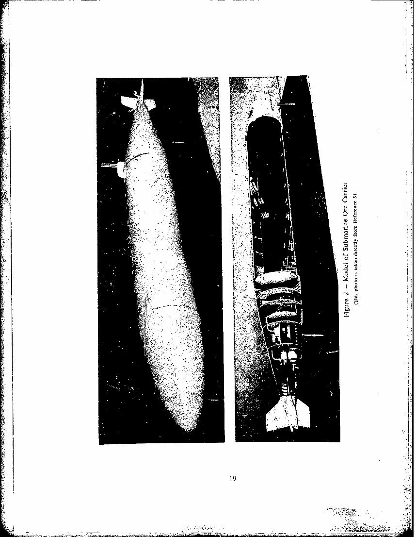
has.From the technological point of view, a conventional large cargo submarine (Figure 3)
has the most advantages. It is not so costly to build and is perhaps easier to operate and
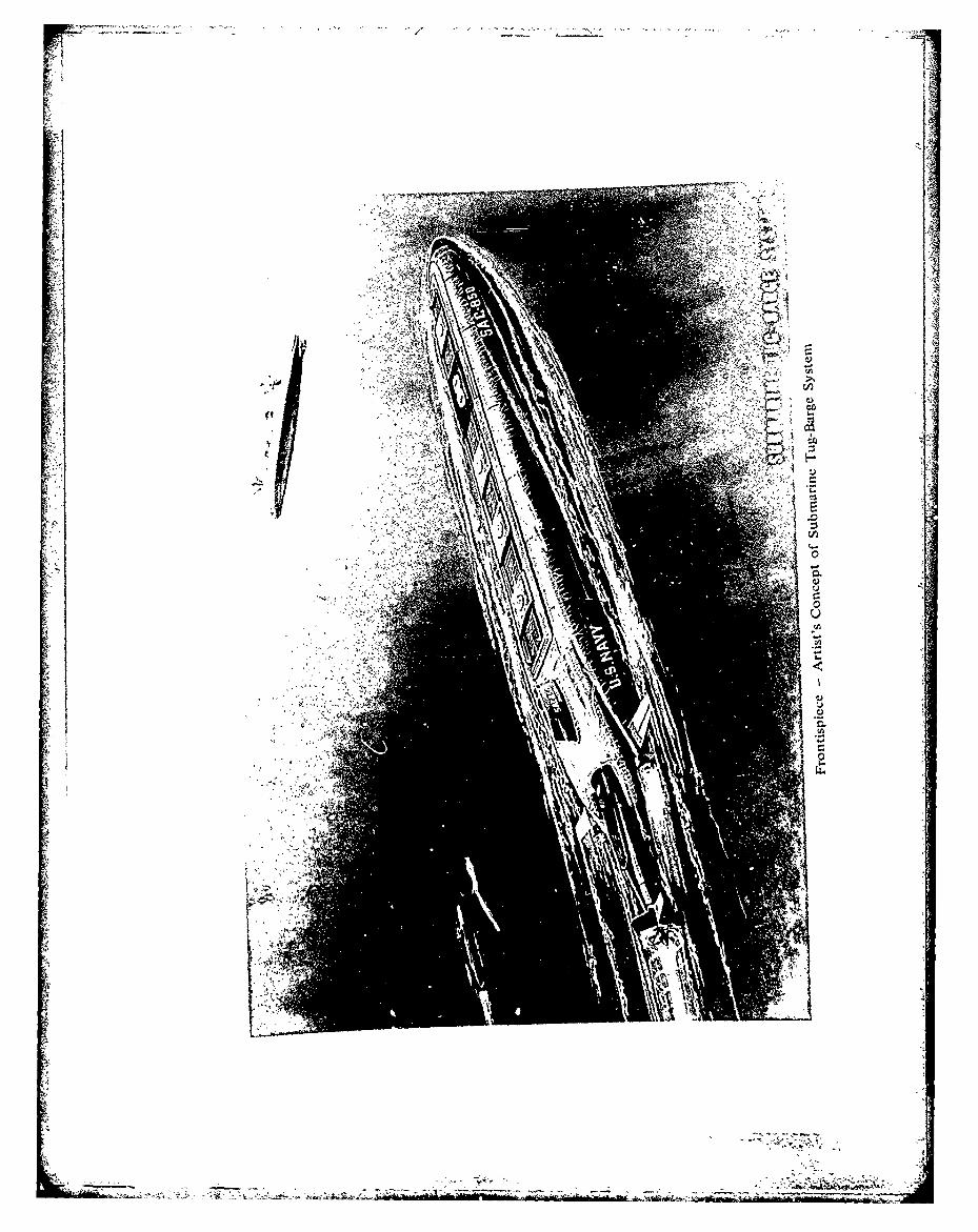
" ,- maintain. For the flexibility of interchanging cargo modules to suit their missions, the modu-lar configuration (Figure 4) may be applicable.
The advantages of the tug-barge configuration (Figure 5) over the others are:1. Less Vulnerability-the loss of the barge may not mean loss of the tug or vice versa.
2. Lower Unit Cost-the most costly part of the ship system would be the nuclear power
plant. The tug-barge system needs fewer power plants than a conventional ship system. Subse-
quently, this will reduce the initial cost, as well as operational cost.
3. More Operating Days-both tug and barge can be operated separately or as an inte-grated unit. This will minimize the idle time ir. port and, in turn, increase the overall opera-
tional efficiency.
The disadvantages include the need for advanced technology in construction and for
more skillful personnel for operation. These disadvantages raise the cost slightly above that
of a large single submarine.
For the purpose of general exploration, three sizes of cargo carriers, configured as con-
ventional submarines or as the tug-barge combinations, were investigated. The tug-barge con-
fig,,ration was selected for further analysis in various options because of its genetic similarity
to others, in addition to its own unique characteristics. Table 4 compares the principal
characteristics of the three systems with the tug-barge configurations. TB-I and TB-2 are
essentially the same in design, except for their capacities. TB-3 is also similar in general
arrangement, but designed for a relatively shallow draft. A conventional large submarine
would have essentially the same overall characteristics as those shown in the table. In all
cases, the tug-barge systems operate as an integrated system where a pusher submarine (power
tug) is linked rigidly with a much larger cargo module (barge); and they are operated together
as a singie unit. The following discussion will apply to either a conventional or the tug-barge
system.
Since virtually no work has been done on the containerized underwater logistic system,this effort has focused on submarines to carry dry cargo, and specifically configured to handle
6

the 8- by 8- by 20-foot standard containers. As noted earlier, a 15-ton minimum gross weight
or an average gross volume density of 85 cubic feet per ton s assumed. Maximum containerweight is 20 tons. These are referred to as the maximum and minimum container weights in
Table 4.
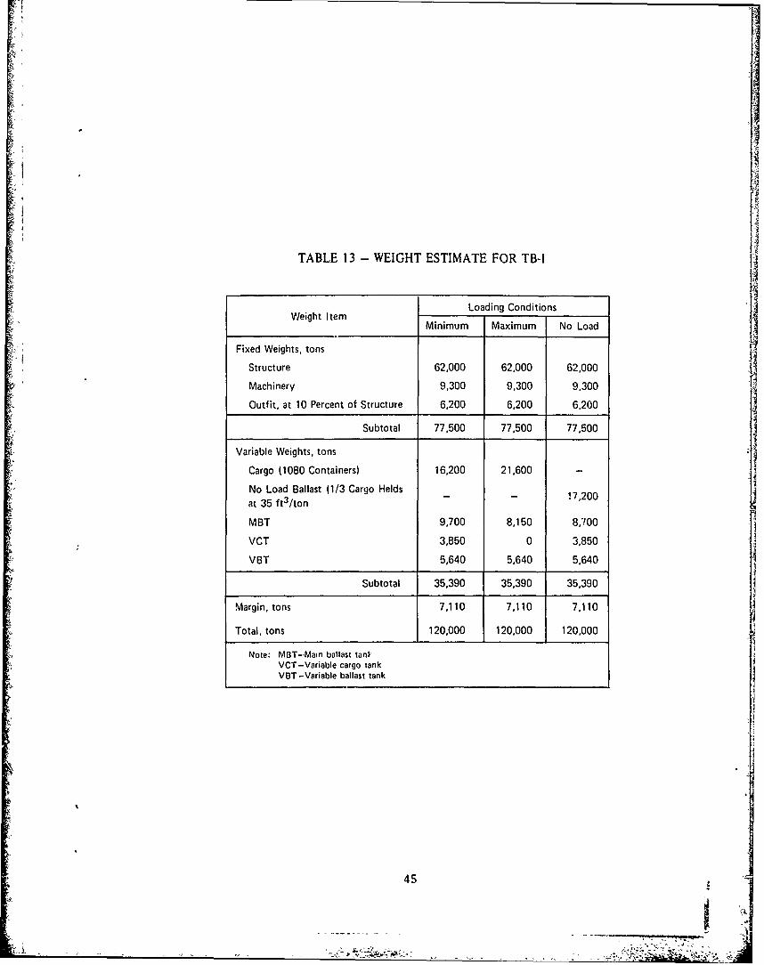
For missions which have no cargo on their return trips, one out of three cargo holdswill have to be designed for containers as well as for ballast. These cargo holds can be usedas seawater ballast tanks on their return missiois. -his no-load condition will be examined
and results will be presented later, in Table 13.The cargo module is essentially a modern underwater container ship. The relatively
light density of containerized cargo together with a moderate depth of submergence resultsin significantly different criteria for structural design of the submarine pressure hull than has
been used for combatant submarines. Usually, the designer's concern is with minimization of
weight; but here the problem is one of increasing weight to achieve neutral buoyancy andsubmergence.
For combatants, in almost all cases it is desirable that the pressure hull have as high astrength-to-weight ratio as possible so that hull structural weight is at a minimum. If the
usual circular pressure hull is considered for cargo carriers, the combination of the lightweight
pressure hull and low-density cargo requires great quantities of ballast for submergence. In
some cases the required ballast water cannot be provided, and the cargo submarine cannot be
submerged.
An array of arrangements and material combinations has been investigated in order to
compare the efficiencies of the ship configurations. The results indicate the square-with-rounded-corners cross-sectional pressure hull with mild steel and partial concrete construction
is promising. The general arrangements of submarine tug-barges TB-I (Figure 6) and TB-3
(Figure 7) are basically identical except TB-3 is designed for a much shallower surfaced draft.Both employ rectangular-with-rounded-corners cros, sectional pressure hulls. With this arrange-
ment, cargo capacities (volume) for TB-I and TB-3 can be improved by 22 and 24 percent,
respectively, relative to a circular hull form.
A special structural problem of the pressure hull is the requirement for large accesshatches through which to move cargo containers. These large accesses will place a severe
requirement on the structural design. However, it is believed that these hatches can be
developed with technology in-hand, and no serious problems are anticipated.
SPEED, POWER AND SUBMERGENCE
The resistance of a submarine is generally made up of a frictional component and form
drag contributions of hull and appendages. Deeply submerged submarines create no surface
disturbance and therefore the wavemaking drag is negligible. This is not the case for a
7
89V

submarine operating near the surface, however. In this instance, the extent of surface dis-
turbance increases with decreasing submergence and the wavemaking contribution and total
drag increases accordingly.
The container-carrying submarine is envisioned as operating near the surface, as there is
little need to operate at deep depths. To establish a minimum reasonable operating depth,
computations were performed to assess the wavemaking drag penalty for near-surface opera-
tion. The effective horsepower (EHP) associated with a particular form, speed and depth of
submergence were predicted by methods in use at the Center, 10 augmented by Pien's Wave-Making Resistance Computer Program."
For estimating the total shaft horsepower (SHP) required for propulsion, a propulsive
coefficient of 0.70, an appendage allowance of 15 percent (for the bridge fairwater, rudders,
stern and bow diving planes, flooding holes, etc.) and service margin of 10 percent are
assumed.
For determining the adequate operating depth, the speed and power curves (Figures 8
and 9) of both submarine tug-barges TB-I and TB-3 were developed (TB-2 has the same hullform as TB-I ; therefore no power curve was developed). In both cases, it is found that the
maximum operating depth of three hull diameters (to the top of the hull) from the free sur-
face are needed to avoid most wavemaking resistance in ship speed up to 30 knots.
The general relationships of the speed, power and submergence in different hull forms
are presented in Table 5. It should be noted that the squared round-corner form has superior
transport efficiencies in all speeds, and the efficiency gap gets wider when it reaches the higher
speed regime. However, the rectangular form does have a higher cargo capacity factor, and
can be operated at shallower draft.
OTHER HYDRODYNAMIC ANALYSES
This section addresses the submerged stability, control, and maneuverability as well as
surfaced motions and wave-induced sea loads of the proposed submarine systems. Due to the
large size and unusual configuration of the ship, its hydrodynamic characteristics may become
key determinants of the feasibility of the concept. For this reason, the TB-I configuration
was selected to be more thoroughly studied. 1 2 The pertinent results are presented here.
10 Gertler, M., "The Prediction of the Effective lorsepower of Ships by Methods in Use at the David Taylor ModelBasin," David Taylor Model Basin Report 576 (Dec 1947).
Chen, R., "The hen's Wave-Making Resistance Computation Program," NSRDC Report 4370 (Mar 1974).
12Sheridan, D. J., "Analytical Evaluation of the Submerged Dynamic Stability and Control and of the Surfaced Motion'sand Dynamic Loads for a Proposed Tug-Barge Submarine, TB-I," NSRDC Report 4379 (in preparation).
8
- - ,

PHYSICAL CHARACTERISTICS
To provide the basic information used for the initial hydrodynamic analysis, only the
plan and profile of TB-I were roughly faired as shown in Figure 10. The pertinent geometric
properties and weight distribution for the ship floating at full load draft of 70 feet were
generated by a computer program. 13 The results are summarized in Table 6.
The weight distribution curve (Figure I I) was developed by assuming that 91 percent of
the barge weight was evenly distributed between Stations 2 and 15, 3 percent was forward of
Station 2, and 6 percent was aft ofStation 15. For the power tug itself, it was assumed that
45 percent of its weight is distributed aft the midship of the tug and 55 percent forward of
the midship.
Estimates of appendage sizes and locations required to achieve acceptable submerged
dynamic stability characteristics were made either by extrapolating available empirical data or
by analytic techniques. For simplicity rectangular planform shapes and sectional shapes
typical of submarine appendages were assumed. Their pertinent characteristics are listed in
Table 7, and their principal dimensions are shown in Figures 12 and 13. It should be noted
that the barge bridge fairwater was assumed to be 30 percent flapped so that the fairwater
could be used as a rudder to assist in turning the submerged TB-I. No bridge fairwater was
designed for the tug since such an appendage of reasonable size would contribute little to the
dynamic stability of the whole system.
SUBMERGED DYNAMIC STABILITY
The dynamic stability characteristics of the TB-i when deeply submerged were assessed
on the basis of Bottaccini's stability criterion 14 which measures the relative dynamic stability
in both horizontal and vertical planes by an "index of stability," G.
The value of G is speed independent in the horizontal plane. In the vertical plane the
value of G indicates the degree of dynamic stability at an infinite speed. If the submarine is
unstable at infinite speed, the extent of the unstable region must be determined including the
effects of the specific speed considered. This approach is considered valid since, if a ship is
stable at infinite speed, it will be stable throughout its entire speed range.
A value of G close to 1 .0 implies a very high degree of stability, while a value of G only
slightly greater than zero indicates a maiginal stability. Therefore, a ship must possess a
reasonable positive value of G, if it is dynamically stable. The indexes of deeply submerged
13Sheridan, D. J. et al., "Manual of NSRDC Ship Motion and Sea Load Computer Program," NSRDC Report 3376 (inpreparation).
14B3ottaccin|, hl. R., "The Stability Coefficients of Standard Torpedoes," NAVORD Report 3346 (Jul 1954).
9

stability for TB I in various configurations have been calculated and summarized in Table 8.
The results indicate that the fully appended configuration has good stability in both the hori-
zontal and vertical planes.
It should be noted that operation of TB-I in the submerged mode, but near the free
surface. may result in a degradation of the controllability of the vehicle. Positive vertical
stability seems to be quite adequate for the system, and at 300 feet, free surface effects should
be relatively small.
TURNING
The submerged turning diameter for a steady flat turn in the horizontal plane, and the
time to reach executed pitch angle in the vertical plane have been estimated using the methods
of Gertler and Hagen. 5
The results indicate that the TB-I submarine will have a submerged turning diameter of
about 3 shiplengths when both the barge and the tug rudders are set at 35 degrees deflection
at speed range of 10-20 knots. No assessment of the surfaced turning diameter was made,
but it is expected to be considerably greater than that of the submerged condition, especially
when only the tug rudders would be available for producing turning forces.
For assessment of the effectiveness of control of vertical plane, two conditions with 15-
degree sternplane deflection were made. First, the sternplanes of both the barge and the tug
were deflected simultaneously, and second, the tug sternplanes alone were deflected. The
results are presented in Figure 14.
It should be noted that the curve for applying the tug sternplane alone is not extended
below 10 knots. This means that the TB-I could have difficulty in attaining a pitch angle of
5 degrees below this speed, because the tug sternplanes cannot generate enough moment to
overcome the metacentric restoring moment in this condition. If the barge sternplanes are
used together with that of the tug, a similar situation exists for a speed of 4 knots or less.
It appears that the TB-I can be better controlled by using tug and barge sternplanes
together. Although it will be sluggish in its response, at its maximum submerged speed of
20 knots the TB-I will require about 18 seconds to reach a pitch angle of 5 degrees. Such
sluggishness can be attributed primarily to its large size.
SURFACED MOTIONS
The surfaced motions of the submarine tug-barge TB-I and its sea loads induced by waves
were predicted.13 They included the motions of heave, pitch, sway, roll and yaw as well asthe vertical shear forces, bending, and torsional moments.
1Gertder, M. and C. lagen, "Standard Lquations of Motion of Submarine Simulation." NSRDC Report 2510 (Jun 1967).
10
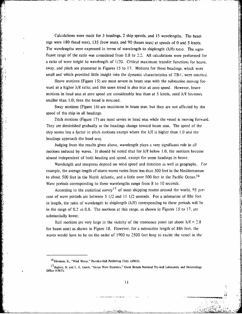
Calculations were made for 3 headings, 2 ship speeds, and 15 wavelengths. The head-
ings were 180 (head seas), 135 (bow seas), and 90 (beam seas) at speeds of 0 and 5 knots.
The wavelengths were expressed in terms of wavelength to shiplength (X/Q) ratio. The signi-
ficant range of the ratio was considered from 0.8 to 2.2. All calculations were performed for
a ratio of wave height to wavelength of 1/20. Critical maximum transfer functions for heave.sway, and pitch are presented in Figures 15 to 17. Motions for those headings, which were
small and which provided little insight into the dynamic characteristics of TB-I, were omitted.Heave motions (Figure 15) are most severe in beam seas with the submarine moving for-
ward at a higher X/Q ratio; and this same trend is also true at zero speed. However. heave
motions in head seas at zero speed are considerably less than at 5 knots, until X/2 becomes
smaller than 1 .0; then the trend is reve;sed.
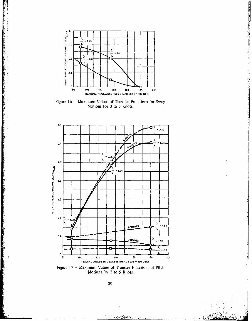
Sway motions (Figure 16) are maximum in beam seas. but they are not affected by the
speed of the ship in all headings.
Pitch motions (Figure 17) are most severe in head seas while the vessel is moving forward.
They are diminished gradually as the headings change toward beam seas. The speed of the
ship seems less a factor in pitch motions except where the X/2 is higher than 1 .0 and the
headings approach the head seas.
Judging from the results given above, wavelength plays a very significant role in all Imotions induced by waves. It should be noted that for X/9 below 1.0. the motions become
almost independent of both heading and speed, except for some headings in heave.
Wavelength and steepness depend on wind speed and duration as well as geograph.,. For
example, the average length of storm waves varies from less than 300 feet in the Mediterranean
to about 500 feet in the North Atlantic, and a little over 500 feet in the Pacific Ocean. 16
Wave periods corresponding to these wavelengths range from 8 to 10 seconds.
According to the statistical survey17 of most shipping routes around the world. 95 per-
cent of wave periods are between 5 1/2 and 11 1/2 seconds. For a submarine of 886 feet
in length, the ratio of wavelength to shiplength (X/2) corresponding to these periods will be
in the range of 0.2 to 0.8. The motions at this range, as shown in Figures 15 to 17, are
substantially lower.
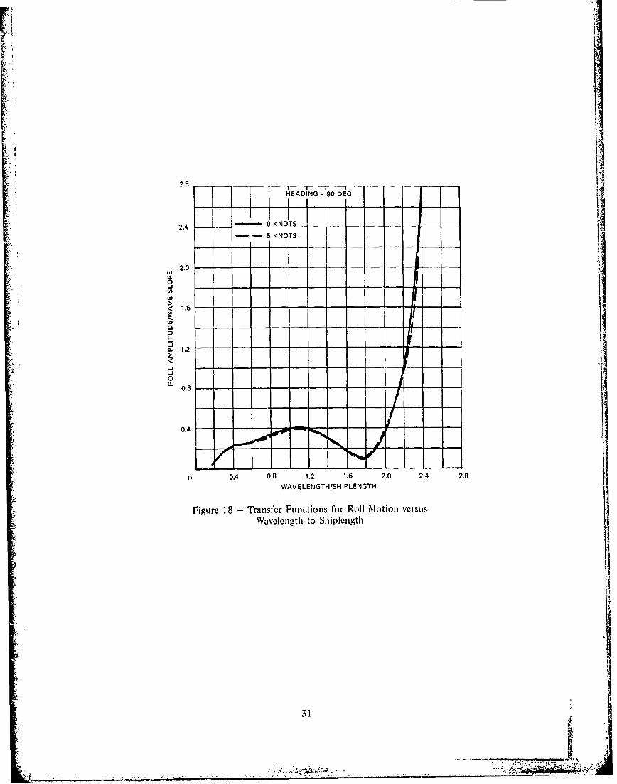
Roll motions are very large in the vicinity of the resonance point (at about X/Q = 2.8
for beam seas) as shown in Figure 18. However, for a submarine length of 886 feet. the
waves would have to be on the order of 1900 to 2500 feet long to excite the vessel in the
16 Kininan, B., "Wind Waves," Prentice-Ilall Publiqhing Corp. (1965).
1711agben, N. and I . E. Luinb, "Otean Wave Statistics," Great Britain National Ph)sical Laboratory and Metcorolog)Office (1967).
?I
K; .
* 2 " Y
resonance regime. The likelihood of experiencing such steep waves of this wavelength is
quite remote (foi comparison a Pierson-Moskowitz State 9 sea has an average wavelength of
about 1313 feet). Roll motions in head seas are zero.
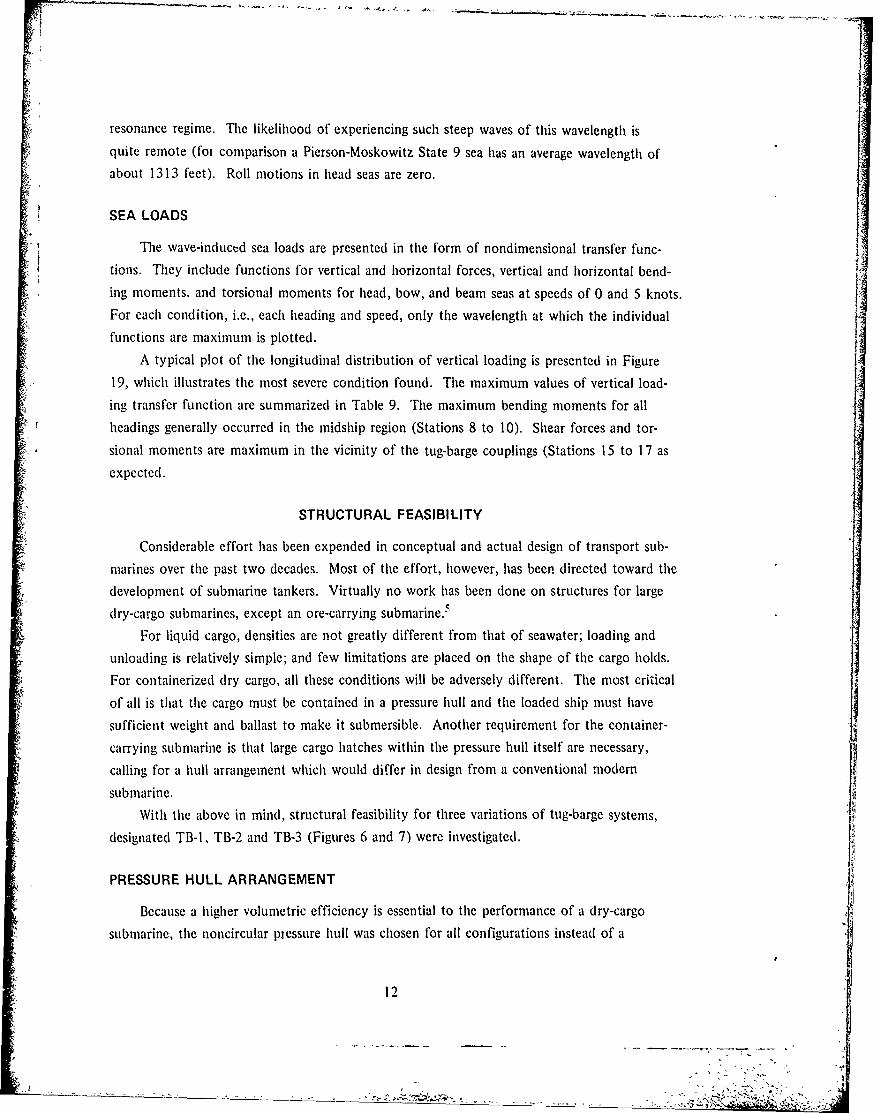
SEA LOADS
The wave-induced sea loads are presented in the form of nondimensional transfer func-
tions. They include functions for vertical and horizontal forces, vertical and horizontal bend-
ing moments, and torsional moments for head, bow, and beam seas at speeds of 0 and 5 knots.
For each condition, i.e., each heading and speed, only the wavelength at which the individual
functions are maximum is plotted.
A typical plot of the longitudinal distribution of vertical loading is presented in Figure
19, which illustrates the most severe condition found. The maximum values of vertical load-
ing transfer function are summarized in Table 9. The maximum bending moments for all
headings generally occurred in the midship region (Stations 8 to 10). Shear forces and tor-
sional moments are maximum in the vicinity of the tug-barge couplings (Stations 15 to 17 as
expected.
STRUCTURAL FEASIBILITY
Considerable effort has been expended in conceptual and actual design of transport sub-
marines over the past two decades. Most of the effort, however, has been directed toward the
development of submarine tankers. Virtually no work has been done on structures for large
dry-cargo submarines, except an ore-carrying submarine.5
For liquid cargo, densities are not greatly different from that of seawater; loading and
unloading is relatively simple; and few limitations are placed on the shape of the cargo holds.
For containerized dry cargo, all these conditions will be adversely different. The most critical
of all is that the cargo must be contained in a pressure hull and the loaded ship must have
sufficient weight and ballast to make it submersible. Another requirement for the container-
carrying submarine is that large cargo hatches within the pressure hull itself are necessary,calling for a hull arrangement which would differ in design from a conventional modern
submarine.With the above in mind, structural feasibility for three variations of tug-barge systems,
designated TB-l, TB-2 and TB-3 (Figures 6 and 7) were investigated.
PRESSURE HULL ARRANGEMENT
Because a higher volumetric efficiency is essential to the performance of a dry-cargo
submarine, the noncircular piessure hull was chosen for all configurations instead of a
12

conventional circular one. The configurations of TB-I and TB-2 are essentially identical in
structure as well as arrangement except for the total number of cargo holds. TB-3 is designed
for a relatively shallow draft; therefore a rectangular cross-section pressure hull was introduced.
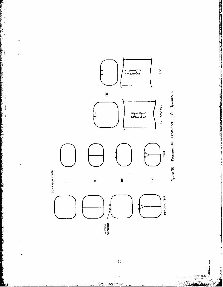
Five structural configurations depicted in Figure 20 were analyzed. Configuration I
represents the hull cross section where no cargo loading hatch opening is located. Such a
section can be treated as a continuous ring; and it can be strengthened with a vertical support
at the center of the section, as shown in Configuration 11.
Configuration III shows the hull section which contains a hatch opening at its top
center. If reinforcement is required, a vertical support can be added at the fore and aft
boundaries of the hatch as in Configuration IV, or a longitudinal beam may be used on each
side of the hatch as in Configuration V.
All hatches are oriented in a single row longitudinally at the top center of the cargo
holds and their openings are assumed to be 10 by 22 feet for shipping/unshipping 8 by 8
by 20 foot containers.
STRENGTH ANALYSIS
The collapse depth for the submarine pressure hull was chosen as 1000 feet,* which
corresponds to an external hydrostatic pressure of 445 psi. The design approach taken for
these hulls differs from a conventional approach by nature of the noncircular hull shape and
the presence of large hatches along the top-center of each hull. Because of this geometry.
the hull structure will experience considerably more bending than a circular hull, and the
structural members will tend to be more massive. High yield strength steels can effectively
reduce the structural mass but will cause increased costs for the material and its fabrication.
The structural design problem, then, is to establish configurations which use moderate
strength materials that are easily fabricated.
For a conventional submarine, the design of a cylindrical hull consists principally of
ensuring against three types of failure: circumferential yielding of the shell and/or frame
which leads to collapse, local buckling of the shell between frames, and overall buckling of
the shell-frame combination. Any circumferential bending, if present at all, is only inciden:tal,
arising from the out-of-roundness of the hull.
For noncircular hulls, such as those for TB-I, TB-2 and TB-3, however, substantial bend-
ing will occur for all loads, because of the marked deviation from circularity. The problem is
to provide sufficient rigidity in the shell structure to resist this bending, since overall buckling
is not considered to be a serious problem.
*Calculations were not made at this stage of concept feasibility to determine the speed/vertical plane control/depthenvelope.
13
Ali
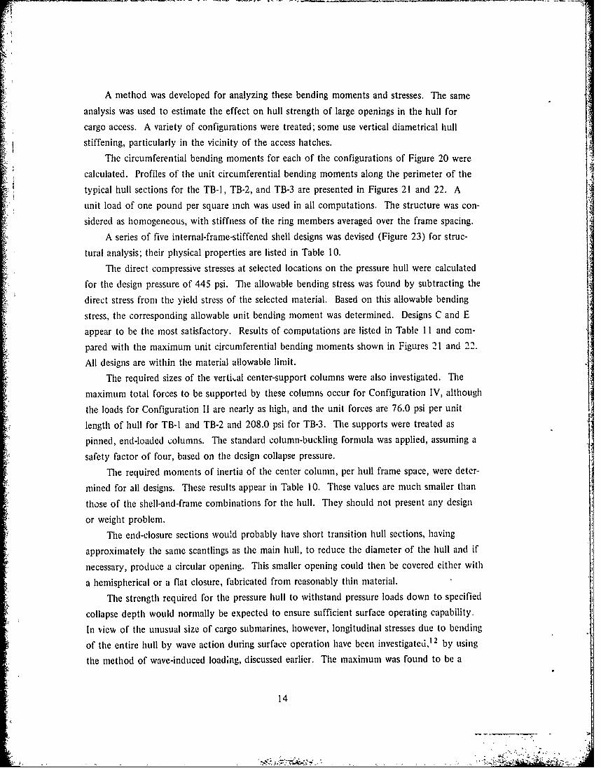
A method was developed for analyzing these bending moments and stresses. The same
analysis was used to estimate the effect on hull strength of large openings in the hull for
cargo access. A variety of configurations were treated; some use vertical diametrical hull
stiffening, particularly in the vicinity of the access hatches.
The circumferential bending moments for each of the configurations of Figure 20 were
calculated. Profiles of the unit circumferential bending moments along the perimeter of the
typical hull sections for the TB-1, TB-2, and TB-3 are presented in Figures 21 and 22. A
unit load of one pound per square inch was used in all computations. The structure was con-
sidered as homogeneous, with stiffness of the ring members averaged over the frame spacing.
A series of five internal-frame-stiffened shell designs was devised (Figure 23) for struc-
tural analysis; their physical properties are listed in Table 10.
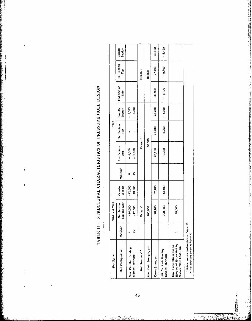
The direct compressive stresses at selected locations on the pressure hull were calculated
for the design pressure of 445 psi. The allowable bending stress was found by subtracting the
direct stress from the yield stress of the selected material. Based on this allowable bending
stress, the corresponding allowable unit bending moment was determined. Designs C and Eappear to be the most satisfactory. Results of computations are listed in Table 11 and com-pared with the maximum unit circumferential bending moments shown in Figures 21 and 22.
All designs are within the material allowable limit.
The required sizes of the verti,al center-support columns were also investigated. The
maximum total forces to be supported by these columns occur for Configuration IV, although
the loads for Configuration II are nearly as high, and the unit forces are 76.0 psi per unit
length of hull for TB-I and TB-2 and 208.0 psi for TB-3. The supports were treated as
pinned, end-loaded columns. The standard column-buckling formula was applied, assuming a
safety factor of four, based on the design collapse pressure.
The required moments of inertia of the center column, per hull frame space, were deter-
mined for all designs. These results appear in Table 10. These values are much smaller than
those of the shell-and-frame combinations for the hull. They should not present any design
or weight problem.
The end-closure sections would probably have short transition hull sections, having
approximately the same scantlings as the main hull, to reduce the diameter of the hull and if
necessary, produce a circular opening. This smaller opening could then be covered either with
a hemispherical or a flat closure, fabricated from reasonably thin material.
A.The strength required for the pressure hull to withstand pressure loads down to specified
collapse depth would normally be expected to ensure sufficient surface operating capability.
In view of the unusual size of cargo submarines, however, longitudinal stresses due to bending
of the entire hull by wave action during surface operation have been investigated,'2 by using
the method of wave-induced loading, discussed earlier. The maximum was found to be a
14
- -. . .. . -., " ' " ' ,, ' " -
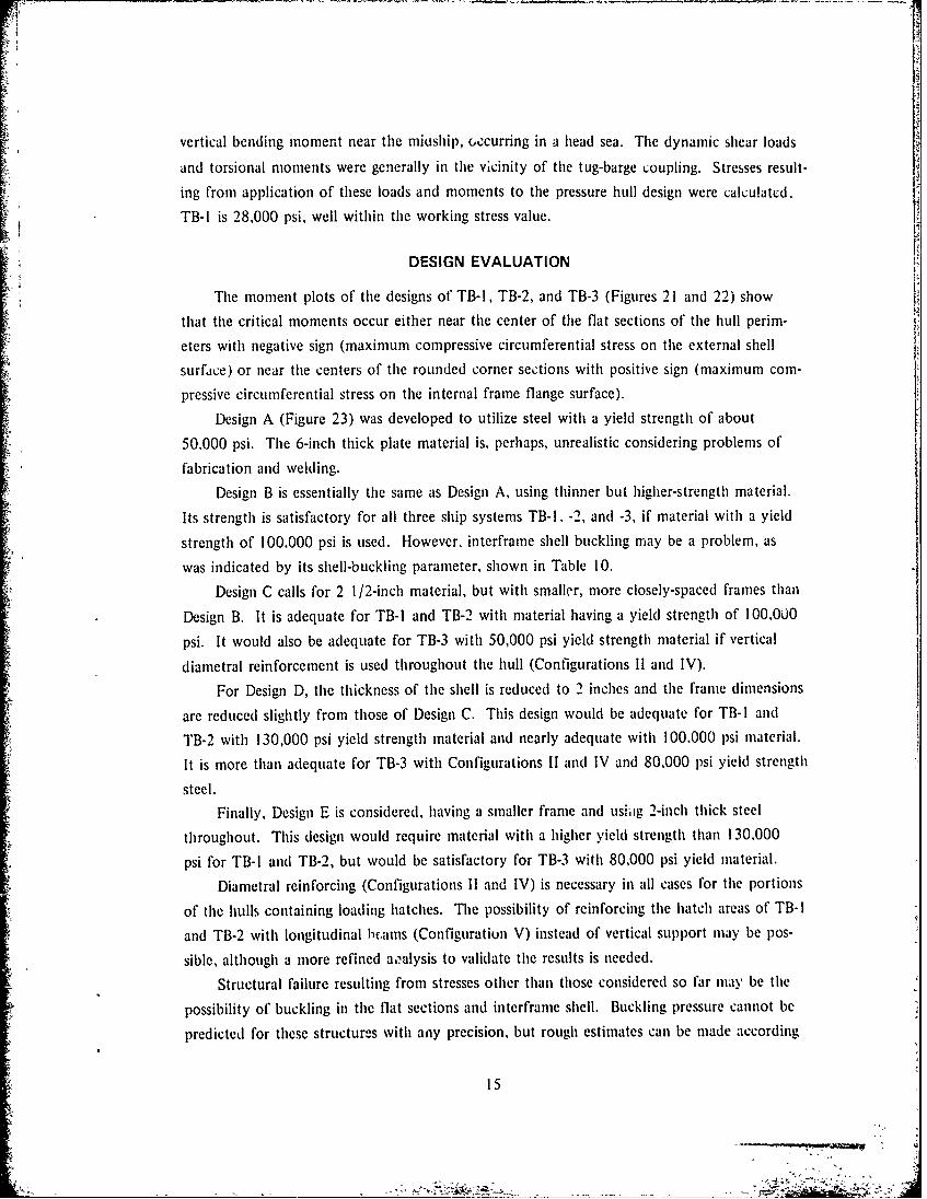
vertical bending moment near the miuship, ,ccurring in a head sea. The dynamic shear loads
and torsional moments were generally in the vicinity of the tug-barge coupling. Stresses result-
ing from application of these loads and moments to the pressure hull design were calculated.
TB-I is 28,000 psi, well within the working stress value.
DESIGN EVALUATION
The moment plots of the designs of TB-I, TB-2, and TB-3 (Figures 21 and 22) show
that the critical moments occur either near the center of the flat sections of the hull perim-
eters with negative sign (maximum compressive circumferential stress on the external shell
surface) or near the centers of the rounded corner sections with positive sign (maximum com-
pressive circumferential stress on the internal frame flange surface).
Design A (Figure 23) was developed to utilize steel with a yield strength of about
50.000 psi. The 6-inch thick plate material is, perhaps, unrealistic considering problems of
fabrication and welding.
Design B is essentially the same as Design A, using thinner but higher-strength material.
Its strength is satisfactory for all three ship systems TB-I, -2, and -3, if material with a yield
strength of 100,000 psi is used. However, interframe shell buckling may be a problem, as
was indicated by its shell-buckling parameter, shown in Table 10.
Design C calls for 2 1/2-inch material, but with smaller, more closely-spaced frames than
Design B. It is adequate for TB-I and TB-2 with material having a yield strength of 100.000
psi. It would also be adequate for TB-3 with 50,000 psi yield strength material if vertical
diametral reinforcement is used throughout the hull (Configurations 11 and IV).
For Design D, the thickness of the shell is reduced to 2 inches and the frame dimensions
are reduced slightly from those of Design C. This design would be adequate for TB-I and
TB-2 with 130,000 psi yield strength material and nearly adequate with 100,000 psi material.
It is more than adequate for TB-3 with Configurations II and IV and 80.000 psi yield strength
steel.
Finally, Design E is considered, having a smaller frame and usiiig 2-inch thick steel
throughout. This design would require material with a higher yield strength than 130.000
psi for TB-I and TB-2, but would be satisfactory for TB-3 with 80,000 psi yield material.
Diametral reinforcing (Configurations II and IV) is necessary in all cases for the portions
of the hulls containing loading hatches. The possibility of reinforcing the hatch areas of TB-I
and TB-2 with longitudinal h1cams (Configuratiun V) instead of vertical support may be pos-
sible, although a more refined a,:alysis to validate the results is needed.
Structural failure resulting from stresses other than those considered so far may be the
possibility of buckling in the flat sections and interframe shell. Buckling pressure cannot be
predicted for these structures with any precision, but rough estimates can be made according
i5
to Reynolds. 18 The values of the shell buckling parameter, t, given in Table 10, indicate
that circular shell portions for all except Design B have nearly sufficiently close frame spacing.
It is believed that construction of pressure hulls of TB-I and TB-2 of 50,000 psi yield
strength material would be economically impractical since material thicknesses of nearly
6 inches are required (in Design A). A pressure hull could be fabricated from 2 1/2-inch
100,000-psi-yield-strength steel. The calculations indicate that this would be feasible,
utilizing Design C. Even if 2 1/2 inches is taken as the upper limit of material thickness, it
appears, moreover, that the use of 80,000 psi material might be possible, as maximum circum-
ferential stresses for Design C would only reach about two-thirds of yield strength at an opera-
tional depth of 500 feet.
For TB-3, the beneficial effects of diametral vertical support columns at the center of
the hull, and running the full length of the hull (Configurations II and IV), are so great that
the unsupported cases will not be considered. For the supported hull, Design E should be
most satisfactory with 80,000-psi-yield-strength material, and Design C would be feasible with
50,000-psi material.
It is apparent that some additional ballast will be needed. It could be carried in a useful
form as in concrete cargo floor-support or concrete frame-support as shown in Figure 24.
Frames could be deeper, and made of thinner material, and some or all the space between
them could be filled in with concrete to prevent local buckling of the frame components.The maximum available weight of these two types of ballast that could be accommodatedwith Designs C and E are given in Table 12. This is evidently more than is needed for neutral
submerged buoyancy in every case, so that only a portion of available weight capacity would
actually be used.
Rough estimates of the pressure-hull weights for representative designs and some weight-
displacement ratios have also been calculated and appear in Table 12. For these calculations
it has been assumed that weights and displacements of the end closure structures will be
comparable to hemispherical heads. The pressure hull weight (Design C) of TB-I has been
incorporated in the estimated total weight of the barge (Table 13). It appears that the weight
of such a design augmented by permanent ballast could make this ship system submersible.
CONCLUSIONS
The concept of a submarine system for logistics and replenishment, either in a conven-
tional or tug-barge configuration, appears technically feasible insofar as it has been examined.
8RyodT. E., "Elastic Labor Buckling of Ring-Supported Cylindrical Shells Under Hydrostatic Pressure." DavidTaylor Model Basin Report 1721 (Jul 1966).
16
- N. - 7 -

This conclusion is tempered by the belief that more thorough investigations would be required
to fully establish the feasibility and practicality of some of the more detailed aspects of the
concept. Matters which have not been investigated include container handling and transfer,
joining of power unit and barge, watertight hatch closures and stability under varying loading
conditions. Negative findings in these areas may invalidate the concept.
The geometry of a container-carrying submarine requires substantial departure from the
conventional, circular pressure hull shape. The analysis indicates that, for shallow operation a
square section with rounded corners is the preferred configuration. This cross section yields
significantly increased volume capacity relative to the circular shape.
The high volumetric capacity produces a weight problem which is the reverse of that
normally encountered. Even in fully-loaded condition the cargo submarine cannot submerge
without the addition of large amounts of fixed ballast. For the configurations examined, the
space required to locate the required ballast appears to be available. This insensitivity to
weight allows much more latitude in selection of structural concepts. With the requirement
for minimum weight structure removed, it may be possible to develop hull and structural
configurations more suitable for cargo carriage and less costly to fabricate. The assumption
of 15-20 tons per container has an important effect on the conclusions of this study. Lighter,
average cargo loads increase the magnitude of the weight problem in a manner detrimental to
the concept.
Except at very low speeds, large submarines are dynamically stable and controllable.
Low speed control requires further study. Primarily because of size, however, submarine
response to control surface settings will be sluggish.
The transport efficiency (defined as ton-miles of cargo per shaft horsepower) of a cargo
submarine is less than half that of a comparable surface containership at a similar speed.
This lower efficiency, coupled with higher ship acquisition and operations costs, makes the
submarine option unattractive in normal circumstances. Considerations related to covert
transport, or high attrition rates for surface operation might, however, change the balance in
favor of the submarine cargo ship.
ACKNOWLEDGMENTS
The author is particularly indebted to Mr. R. V. Raetz of the Structures Department for
his contribution on structures, especially for the development of a method for analyzing bend-
ing stress in a noncircular hull, and to Mr. D. J. Sheridan of the Ship Performance Departmert
for his contribution on hydrodynamics. Special thanks are also expressed to Mr. R. M.
Stevens and others who provided technical reviews and vaiuable comments to improve the
contents of the report.
17
77
PRESSURE ICE BREAKER 1RIDGE 166,000 HP
ICE150,1-2 MILE4!
IceA Field
18
-, --
I>
I-
I-
46 -~ .'~-~
UI-. e)
2c~2- (~
o0.
c1.~ V
VLi~
19Ii ~'4
~ ~
t
bV
-'--- I I
cr2
0 I>0 71;~~K
~
\\0 -
~ I~v..
'1
21
K~PAGEB~K-NOTFIU4ED~ft
-- ~.
....- . ,,.

A ~
4 {
(AI-
0
&
'I
22 '4
_____________ ______ ~

III
!i 'C
tI II-
23H

766'
140' 0
I L v.'A--- X__ ,, 1x- -
CARGO HOLD"' CARGO HOLD/
LL
MIDSHIP' SECTIONt
Figure 6 - General Arrangement of Submarine Tug-Barge TB-I
746'
CARGO HOLD CARGO HOLD'
F-48'
MIDSHIP SECTION
Figure 7 - General Arrangement of Submarine Tug-Barge TB-3
24

08
(N N'
00~ Z
wI %
z~C
% %N (L
D 00%U
00
U)
COL/dHSV
25uLL4
LL ON % L

o o 0 LL
c'J h
IT0
U- w
0 0
cc ,D 20 0
o 0 -
a: 0
In.
NC
1 0 cS
tL '4A
%N %
% 0
coc
C4
0 0
0
22
ix a

NOTE LOAD WATERLINE
-_--,*; 1 ALL DIMENSIONS ARE IN FEET .1- 2 THIS SKETCH IS NOT TO SCALE_ 3 STATION SPACING IS 44 3 FEET
I I I ,,BASELINE
: 77 52 40 20 0 20 40 52
1205
705
"20 19 18 17 16 15 14 13 12 11 10 9 8 7 6 5 4 3 2 I 0
SA P STATIONS P
~Figure 10 - Body Plan and Profile of Submarine Tug-Barge TB-I
~FLOATING CONDITIONS AT FULL L.OAD DRAFT. 70 FT€*- LONGITUDINAL CG - 409.7 AFT OF FP: VERTICAL CG - 40.7 ABOVE BL
10 x0
fB 02
w 4
z 2
'r0 '---- - - - - - -..,20 19 18 17 16 15 14 13 12 11 10 9 8 7 6 5 4 3 2 I 0
" A P. F:,p3STATIONS
. Figure 11 - Estimated Weight Curve for the Submarine Tug-Barge System. TB-I
1227
.1. IS.

653-~~1 NOTES
I. ALL DIMENSIONS ARE IN FEETT- 2 THIS SKETCH IS NOT TO SCALE
950629.7TO FP
0.25 CHO D---'D
Figure 1 - Appendages for TB- BrTg
t
220.
TO FP .,

160w-J
z
- 120
LU
woX Z
W
z TUG STERNF LANES ONLY
LU 40 _ _ _ _ _ _ _ _ _ _ _ _ _ _ _ _ _ _ _
cc TUG AND BARGE0 STERNPLANEST -
0 4 8 12 16 20 24SPEED IN KNOTS
Figure 14 - Control Characteristics for Submarine Tug-Barge TB-I
1.39 5 KNOTS 1.43
-112316
1. - 1.23L
00
x
L
0.
jU
>
80 100 120 140 160 180 2001HEADING ANGLE/DEGREES
Figure 15 - Maximum Values of Transfer Functions for HeaveMotions for 0 to 5 Knots
29
x 116
-2.45p 1.2 L L
0.8 - 0, ,-.
- L04
80 100 120 140 160 180 200
HEADING ANGLE/DEGREES (HEAD SEAS - 180 DEGi
Figure 16 - Maximum Values of Transfer Functions for SwayMotions for 0 to 5 Knots
2.8
2.20
2 . - 1.84L
-2.06
LL
2.,- - .- - -N~ -_., - .- - o
o x
0
1.6---
W
CL
1.2~ KNT 1.2-0. - -
.4
0 OKNOTS -1.20
80 100 120 140 160 180 200
HEADING ANGLE IN DEGREES MHEAD SEAS - 180 DEG)
Figure 17 -Maximun, values of Transfer Functions of PitchMotions for ') to 5 Knots
30
HEADING 90 DEG
2.8 0 KNOTS
-- 5 KNOTS
2.0 NTS___
w
w
00. 8-----------------
0.4 - -
0 0.4 0.8 1.2 1.6 2.0 2.4 2.8
WAVE LENGTH/SH IPLENGTH
Figure 1 8 - Transfer Functions for Roll Motion versusWavelength to Shiplcngth

241~ HEA0'IJGS 180 DEG-------
20
0/.8" 16
z 12 - -
8 'h
0 .
HEADiING -'180 DEG WHERE- X - WAVE LENGTHI- - - L -LSHIP LENGTH
10 AP - MASS DENSITY109 . ACCELERATION OF GRAVITY
___ __ __B - SHIP BEAM
w Ia- WAVE AMP'LITUDE (TROUGH TO CREST)
ccI ____ WAVE HEIGHT -
cn 0
-- X/ 2.2,V, .5- -
HEADING *135 DEG iA/ 0.6 J4... - - - - -
KNOTS
o 130--------------------------- -- -- -
20 18 16 14 12 10 8 6 4 2 0
AP. STATIONS F P
Figure 19 - Transfer Functions for Longitudinal Distribution of
Wave Induced Sea Load
32
<1o
2 1
00
I, A
c-
0U,
zzEE-z0
33

C NFIGURATION 7 5
20 -- It
-o -0 ~-.4 -"1t- I3 3
8 10
z
o-2w I III
8 7 6 5 4 3 2 1
POSTION ON PERIMETER OF HULL CROSS SECTION
Figure 21 - Circumferential Bending Moments in Pressure Hull of TB-i and TB-2
CONFIGURATION
7'S'
678m 20 8
0
N -
Z 10 -
0 -20 -
87 6 5 4 3 2 1POSITION ON PERIMETER OF HULL CROSS SECTION !
Figure 22 - Circumferential Bending Moments in Pressure Hull of TB-3 !
343
12'
zr
IV i, t -0

L
CO0
z TCO1
-.4
C6 C
H 610. C1co I; Cg j0'
T-'03
cc e c~h
35I--I

_j LL
LL.
FLOOR-SUPPORTPRESSURE HULLBALS
BETWEEN-FRAMEBALLAST
Figuire 24 - Location of Permanent Ballast in TB-I and TB-2
36

TABLE 1 - PRINCIPAL CHARACTERISTICS FOR PROPOSED SUBMARINE TANKERS(Measurement is in feet, and tonnage in long tons)
General General MARADSaunders Roe Shigemitsu KobeDynamics Dynamics S5.N.M 48a
170,000 dwt 250.000 dwt 28,000 dwt 20,000 dwt 30,000 dwt
Length b.p. 900 1,020 604 565 590.4
Beam, Molded 140 170 72 80 78.7
At Stern Planes 180 220 - - -
Depth, Hull at Side 85 90 - 40 -
Hull at Centerline 88 93 1/2 72 40 78.7
Cargo Deadweight 172,200 255,380 28,000 20,000 30.000 (metric)
Displacement
Full-Load Surfaced 240,100 353,200 45,400 38,000 48,200 (metric)
Light Ship 67,900 94,900 - - -
Submerged 254,500 370,000 50,000 41,800 -
Draft, Surface 81 85 59 35 1/2 55.7
Light Ship (mean) 24 24 35 - -Minimum Cargo Density 53.6 lb/ft 2 53.6 lb/ft 2
- - -
Crew 49 49 - 56 50
Reactor Plant 250 Mw PWR 250 Mw PWR 150 Mw PWR PWR 180 Mw PWR
Propulsion (by gearedsteam turbines)
Shaft Horsepower 75,000 75,000 50,000 35,000 40,000
Propellers (diam) 2(26 ft) 2(26 ft) 1(25 ft) 1(26.1 ft) 2(17.4 ft)
Revolutions per Minute 105 105 120 100 160
Trial Speed (knots) 19.4 17.3 25 20 22
Service Speed 19.0 16.9 - - -
Depth Range (ft) Design 1,000 1,000 600 1,000 330(approx)
Normal Operation 400 400 200-300 -
7'37
I-7
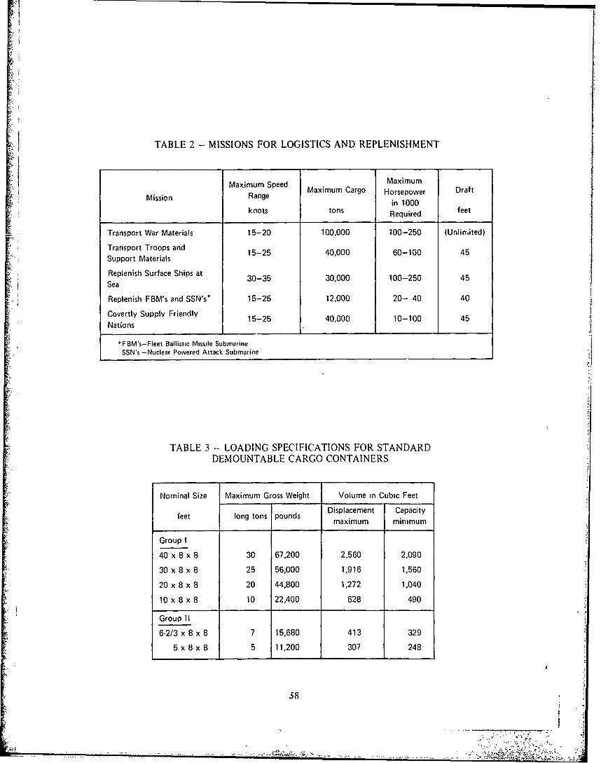
TABLE 2 - MISSIONS FOR LOGISTICS AND REPLENISHMENT
Maximum Speed MaximumMaximum Cargo Horsepower Draft
Mission Rangein 1000
knots tons Required feet
Transport War Materials 15-20 100,000 100-250 (Unlimited)
Transport Troops and 15-25 40,000 60-100 45Support Materials
Replenish Surface Ships at 30-35 30,000 100-250 45Sea
Replenish FBM's and SSN's* 15-25 12,000 20- 40 40
Covertly Supply Friendly 15-25 40,000 10-100 45Nations
*FBM's-Fleet Ballistic Missile SubmarineSSN's -Nuclear Powered Attack Submarine
TABLE 3 - LOADING SPECIFICATIONS FOR STANDARDDEMOUNTABLE CARGO CONTAINERS
Nominal Size Maximum Gross Weight Volume in Cubic Feet
Displacement Capacityfeet long tons pounds maiu mnmmmaximum minimum
Group I
40 x 8 x 8 30 67,200 2,560 2,090
30 x 8 x 8 25 56,000 1,916 1,560
20 x 8 x 8 20 44,800 1,272 1,040
10 x 8 x 8 10 22,400 628 490
Group II
6-2/3 x 8 x 8 7 15,680 413 329
5 x 8 x 8 5 11,200 307 248
38
A.'s

TABLE 4 - PRINCIPAL CHARACTERISTICS OF SUBMARINE TUG-BARGE SYSTEM
Submarine Tug-Barge Submarine Tug-Barge
TB'1 TB-2 Power Tug TB-3 Power Tug
Displacement, tonsSubmerged 130,000 106,000 10,000 86,000 6.000Full Load Surfaced 125,000 96,000 9,150 79,000 5,600
Cargo, Containers 1,080 810 744Tons Max/Min 21 ,600/16,200 16,200/12,150- 14.880/11,160*
Length, feet 890 750 240 846 200
Beam, feet 104 104 50 96 40
Depth, feet 80 80 50 54 40
Draft, Full Load Surface, feet 70 70 44 48 35
Shaft Horsepower 60,000 60,000 60,000 40,000 40,000
Speed, Submerged, maximum knots 20 22 36 19 38
Propeller (Power Tug) 1 1 1 1 1
*Bsdo 0or 15 tons per container
TABLE 5 -, GENERAL RELATIONSHIPS OF SPEED, POWER, AND SUBMERGENCE
Configuration T8.1 TB.3
Hull Form Squared-Round Corner Rectangular
Displacement, Submerged, tons 130,000 86.000
Speed, knots 20 25 20 24 5
Power. SHP 60,000 75,000 115,000 215,000 45,000 75,000 80,000 225.000
240 40 162 27Submergence, feet (3 diaml 11/2 diam) 240 40 Qdjam) (1/2 diam) 162 27
Power Facto., percent" 80 100 54 100 60 100 36 10Di
Transport Efficiency. ton-mile/SHP 46 37 30 1 82 69
Cargo C;apacity Factor'~ 1.22 1 24
'Power Factor of submergence is the ratio of the StiP rensuired lot a ivnr speed at the subineiited idepth to that ot hill hull diameet horn the it"e siuitace
'CrF actor is the ratio of the total number of containers accomamodated in the designred hull turin to that of a circular one
39
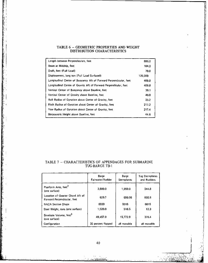
TABLE 6 - GEOMETRIC PROPERTIES AND WEIGHTDISTRIBUTION CHARACTERISTICS
Length between Perpendiculars, feet 886.0
Beam at Midship, feet 104.0
Draft, feet (Full Load) 70.0
Displacement, long ton (Full Load Surfaced) 125,000
Longitudinal Center of Buoyancy Aft of Forward Perpendicular, feet 409.8
Longitudinal Center of Gravity Aft of Forward Perpendicular, feet 409.8
Vertical Center of Buoyancy above Baseline, feet 39.1
Vertical Center of Gravity above Baseline, feet 40.8
Roll Radius of Gyration about Center of Gravity, feet 33.2
Pitch Radius of Gyration about Center of Gravity, feet 217.2
Yaw Radius of Gyration about Center of Gravity, feet 217.4
Metacentric Height above Baseline, feet 44.6
TABLE 7 - CHARACTERISTICS OF APPENDAGES FOR SUBMARINETUG-BARGE TB-1
Barge Barge Tug SternplanesFairwater/ Rudder Sternplanes and Rudders
Planform Area, feet 2
Ponf raee 3,800.0 1,959.0 244.8(one surface)
Location of Quarter Chord Aft ofForward Perpendicular, feet
NACA Section Shape 0020 0018 0015
Steel Weight, tons (one surface) 1,520.0 516.5 12.3
Envelope Volume, feet 3 49,457.0 15,772.9 376.4(one surface)
Configuration 30 percent flapped all movable all movable
40
7jJ ",A
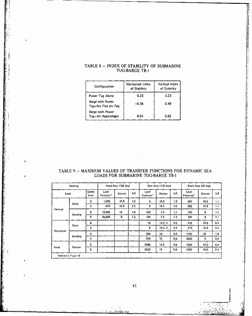
TABLE 8 - INDEX OF STABILITY OF SUBMARINE
TUG-BARGE TB-I
Cniuain Horizontal Index Vertical Index 1Conigratonof Stability of Stability
Power Tug Alone 0.23 0.23
Barge with Power 04Tug-No Fins on Tug-03
Barge with PowerTug-All Appendages 0.24 0.62
TABLE 9 -MAXIMUM VALUES OF TRANSFER FUNCTIONS FOR DYNAMIC SEA£ LOADS FOR SUBMARINE TUG-BARGE TB-I
Heading Head Seas (180 deg) Bow Seas (135 deg) Beam Seas (90 deg)
LodSpeed Load Station ?iIQ Load Station X/~ Load StationLod4knot Fun~ction' Function* Function'
0 1.050 15.5 1.8 8 15.5 1.8 680 15.5 1.11Shear -
5 970 155 2.2 8 15.5 2.0 680 15.5 1 1Vertical-
Bending 0 18.500 1 12 1.8 160 7.5 1.1 160 9 1.15 20,000 8 1.3 190 7.5 1.3 160 9 1.1
0 10 14.5,.5 0.6 210 15.5 04Shear
Hoiotl5 B 14.5. 5 0.6 210 15.5 0.4
0 280 10 0.6 1700 10 1.0Bending 5220 10 0.6 3000 9 0.4
Ail Trin 0 4200 14.5 0.6 1200 15.5 0.4
5 3200 15 0.6 1200 15.5 04
Oeie nFgue 19 -
41

TABLE 10 -GEOMETRIC PROPERTIES OF FIVE HULL STRUCTURE DESIGNS[
Design A B D E
Thickness, t, in. 6.0 2.5 2.5 2.0 2.0Frame Spacing, S. in. 60 60 35 35 35Cioss Sectional Area, A. ofFrame and Shell in one Frame- 729 340 233 200 182Spacing, in2
Circumferential BendingMoment of Inertia, 1, of one 493,600 237,900 100.100 68,800 48,500Frame Space of Hull, in4
C/el, toOuerSrfceo 51.85001-6 103.53(101-6 222 00(10[-6 298.40(101-6 347.31(10)-6
C/I. to Inner Surface of 18lo- 5.0l-6 3250 -6 347()6 58390-,Frame Flange. in-3 8.8116 192(0- 0.31r 8.4116 5 8 9 1
Shell Buckling Parameter. 0* 1.78 2.84 1.61 1.81 1.81
Weight/Di.placement TB.2, 0.418 0.195 0.228 0.196 0.179Ratio
TB.3 0.484 0.226 0.264 0.227 0.207Required Moment ofInertia of Center TB.1, 19,200 19,200 11.200 11,200 11,200Column Cross- TB2Section. Per Frame TB.3 31.600 31,600 18,400 18,400 18,400Space, n4
42
(D Un
C.,
CCo c 0
z .0V) Lei Cd
LL1
0o0
Lu ~ wV) 0..
uu
ed C
CL
~Cc
5, 8
Li5 > 2~0
*0 0
'43

,1o
r, e', ol 0 C' 0 cD 0
- - , -l: - - - -
0
-D 0
0 0 C' (N 0 C) t 0 0'
-*D 0 ; rN R. CD. U' ) -o CM 0 0 06 6 q
U' D 0l
OD
~.4 cc00 0
0i qN cq 0 (D C0 ~ ~ ( (N l I 1 q
H 0 0 l l , l cci 06 C 0a) I CD 0o 0
0D
LLT 0 0
(N -0 0CD 0 ( 0 fl
H6 6 i CD (0 0 Cl)
--
0 IT
C 0 -o (6 4C oo - C
amCo v,4V6 It-~ 0'
cc 0CC - * ..2'~~~~ cl .
,f'~~ 4 -
0 4)'l
E -0 0
2C oo 4a Co 4,4 4,l CL
__ z_ L'
Cl.. ... ___ n
rA
i ii
TABLE 13 -WEIGHT ESTIMATE FOR TB-!
h ILoading ConditionsWeight Item______ _____ _____
Minimum Maximum No Load
Fixed Weights, tons
Structure 62,000 62,000 62,000
Machinery 9,300 9,300 9,300
Outfit, at 10 Percent of Structure 6,200 6,200 6,200
Subtotal 77,500 77,500 77,500
Variable Weights, tons
Cargo (1080 Containers) 16,200 21,600 -
No Load Ballast (1/3 Cargo Helds - 17,200at 35 ft 3/ton
MBT 9,700 8,150 8,700
VCT 3,850 0 3,850
VBT 5,640 5,640 5,640
Subtotal 35,390 35,390 35,390
Margin, tons 7,110 7,110 7,110
Total, tons 120,000 120,000 120,000
Note: MBT--Main ballast tanl,VCT-Variable cargo tankVBT-Variable ballast tank
4
45
, !

REFERENCES
1. Russo, V. L. et al., "Submarine Tankers," SNAME Transactions, Vol. 68 (1960).
2. Todd, F. H., "Submarine Cargo Ships and Tankers," Ship Division, National Physical
Laboratory, Great Britain (Jan 1961).
3. "Is There a Future for the Giant Submarine Oil Tanker?" The Naval Architect,
Journal of the Institute of Naval Architecture, England (Oct 1971).
4. Sudbury, J. D., "Submerged Barges for Arctic Transporation?" Ocean Industry
(Mar 1973).
5. "Submarine Ore Carrier," Shipping World, England (Sep 1959).
6. "Summary of Logistic and Replenishment Submarine," Southwest Research Institute,
prepared for the Office of Naval Research (Jan 1971).
7. "Maritime Report and Engineering News," Maritime Activity Reports, Inc. (Nov
1973).
8. USA Standard Specifications for Cargo Containers (USASI MH5.1), ASME (1965).
9. Darman, W. J. and D. J. deKoff, "Characteristics of Recent Large Container Ship
Designs," Marine Technology (Oct 1971).
10. Gertler, M., "The Prediction of the Effective Horsepower of Ships by Methods in
Use at the David Taylor Model Basin," David Taylor Model Basin Report 576 (Dec 1947).
11. Chen, R., "The Pien's Wave-Making Resistance Computation Program," NSRDC
Report 4370 (Mar 1974).
12. Sheridan, D. J., "Analytical Evaluation of the Submerged Dynamic Stability and
Control and of the Surfaced Motion's and Dynamic Loads for a Proposed Tug-Barge Sub-
marine, TB-I," NSRDC Report 4379 (in preparation).
13. Sheridan, D. J. et al., "Manual of NSRDC Ship Motion and Sea Load Computer
Program," NSRDC Report 3376 (in preparation).
14. Bottaccini, M. R., "The Stability Coefficients of Standard Torpedoes," NAVORD
Report 3346 (Jul 1954).
15. Gertler, M. and G. Hagen, "Standard Equations of Motion of Submarine Simulation,"
NSRDC Report 2510 (Jun 1967).
16. Kinsman, B., "Wind Waves," Prentice-Hall Publishing Corp. (1965).
17. Hagben, N. and F. E. Lumb, "Ocean Wave Statistics," Great Britain National
Physical Laboratory and Meteorology Office (1967).
18. Reynolds, T. E., "Elastic Labor Buckling of Ring-Supported Cylindrical Shells under IHydrostatic Pressure," David Taylor Model Basin Report 1721 (Jul 1966).
46

INITIAL DISTRIBUTION
Copies Copies
1 ARPA 1 Military Sealift Command
10 CNO 2 DDC
1 OP 322
1 OP 961 2, MARAD
1OP 372 1 Ship Construction
1OP 982F 1 R&D
1 0P 981G
1 OP 987 CENTER DISTRIBUTION1 OP 987T6
10P 04B Copies Code
1 OP 0401 OP 405 1 00 CAPT P. W. Nelson
2 CHONR 1 012 R. C. Allen
1 Code 102-0S 1 11 W. M. Ellsworth
1 Code 200 1 1105 B.J. Wooden
11 117
6 NAVMAT 1 R. M. Stevens
1 MAT 0OCA 10 S. W. Liang
1 MAT 03 1 1173 B.V. Nakonechny1 MAT 03L 1 15 W. E. Cummins1 MAT 03R1 MAT 033 1 156 J. Feldman1 MAT 01 1 1564 D. J. Sheridan
1 17 W. W. Murray
1 USNA LIB 2 172
1 M. Krenzke
1 NAVPGSCHOL LIE 1 R. V. Raetz
30 5614 Reports Distribution1 NAVWARCOL 1 5641 Library (C)
12 NAVSEA 1 5642 Library (A)
1 SEA 09G321 SEA 032 SEA 03M4 SEA 0322 SEA 0351 SEA 034111 SEA 035/Sorkin
1 NAVUSEACEN 1311 LIB
1 NAVCOASTSYSLAB
4 NAVSEC1 SEC 61001 SEC 6100B11 SEC 61101 SEC 6114
47