the atlas level-1 muon to central trigger … atlas level-1 muon to central trigger processor...
TRANSCRIPT
The ATLAS Level-1Muon to Central Trigger Processor Interface
(MUCTPI)
Kunihiro Nagano (CERN)
on behalf of the MUCTPI Team:
N. Ellis, P. Farthouat, K. Nagano, G. Schuler, C. Schwick, R. Spiwoks, T. Wengler
“8th Workshop on Electronics for LHC Experiments”
Colmar, France, Sep. 9 – 13, 2002
Contents
I Introduction
I Full-system tests with a prototype and integration tests with external systems
I System performance
I Summary
The ATLAS Level-1 Muon to Central Trigger Processor Interface (MUCTPI) – p.1/17

ATLAS Level-1 Trigger
� ATLAS Level-1 Trigger• Two main trigger systems: calorimeter and muon
• Reduce 40 MHz BC rate → 75 kHz
• Send Region-of-Interest (RoI) information toLevel-2
Preprocessor
ClusterProcessor(e/γ & τ/ h)
Jet/EnergyProcessor(jet & energy)
(RPC)BarrelTrigger
(TGC)EndcapTrigger
Muon-CTP-Interface
calorimeter muon
Central Trigger Processor
Timing, Trigger, Control
detector frontend Level-2Level-1 Muon Trigger
6th Workshop on Electronics for LHC Experiments - 12/09/00 2 of 20
Level-1 Muon Trigger - Strategy
low pT
high pT
5 10 15 m0
RPC 3
RPC 2
RPC 1low p
T
high pT
MDT
MDT
MDT
MDT
TGC 1
TGC 2
TGC 3
MDT
MDT
TGC EI
TGC FI
XX-LL01V04
Tile Calorimeter
Muon Trigger ChambersOverlap
→ identify µ candidates for 6 individually programmable pT thresholds� Barrel: Resistive Plate Chambers (RPCs)� Endcap: Thin Gap Chambers (TGCs)
• Trigger chambers are grouped into sectors
• Tracks: coincidence between layers ofchambers,pT : size of the coincidence window
• Double counting of single µ crossing morethan one sector (“overlap”) must be avoided.→ particularly for low-pT muons (with strongdeflection in magnetic field), overlap maybecome a serious problem
• Expected number of µ candidates:for a typical event:
�
1
The ATLAS Level-1 Muon to Central Trigger Processor Interface (MUCTPI) – p.2/17

Level-1 Muon Trigger System
6th Workshop on Electronics for LHC Experiments - 12/09/00 4 of 20
Level-1 Muon Trigger - System
Sector Logic(TGC)
144 sectors
FE electronics
TGC detector
Sector Logic(RPC)
64 sectors
RPC detector
FE electronics
Sector Logic(TGC)
144 sectors
FE electronics
Sector Logic
Muon-CTP-Interface
Central Trigger Processor
(RPC)
FE electronics
RPC detector TGC detector
64 sectors
DAQinformation on hit strips
DAQ
information on hit strips
Level-2RoI information
DAQ
muon candidate multiplicities
on-detector
off-detector
and wire groups
FE electronics
RPC detector
Sector Logic(RPC)
64 sectors
TGC detector
FE electronics
Sector Logic(TGC)
144 sectors
RPC Resistive Plate ChamberTGC Thin-Gap ChamberCTP Central Trigger Processor
barrel endcap
and RoI information
Muon-CTP-Interface (MUCTPI)
� Evaluates total multiplicity of level-1 µ candidates (max. multiplicity value is limited to 7)− For 6 programmable pT thresholds− Possible overlaps across sectors are resolved
� Input links from: Sector Logic (trigger data)� Output links to: CTP (multiplicity information), Level-2 (Region-of-Interest information),DAQ (event data)
The ATLAS Level-1 Muon to Central Trigger Processor Interface (MUCTPI) – p.3/17
MUCTPI: Architecture
�� �� ��� � �
� � � ��
� � � �
� � �� �� � �� � �
� � � �� � � � � ��
� � �� � � � ��� � �
�! �� ��"# $
%& '( () & *+ %+
� � � � � � � � � �� � , � - � �. � � � �� � � � � / � � � ��
�� � � ��� � � �
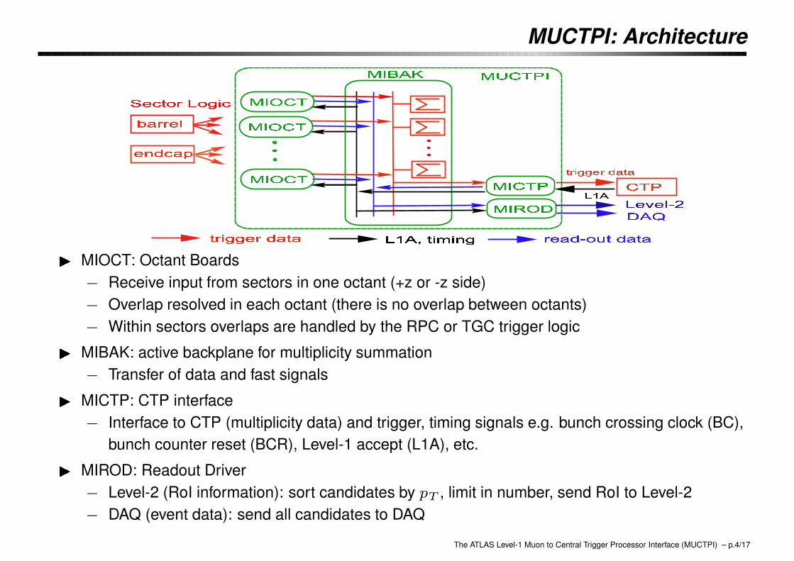
0 MIOCT: Octant Boards− Receive input from sectors in one octant (+z or -z side)− Overlap resolved in each octant (there is no overlap between octants)− Within sectors overlaps are handled by the RPC or TGC trigger logic0 MIBAK: active backplane for multiplicity summation− Transfer of data and fast signals0 MICTP: CTP interface− Interface to CTP (multiplicity data) and trigger, timing signals e.g. bunch crossing clock (BC),
bunch counter reset (BCR), Level-1 accept (L1A), etc.0 MIROD: Readout Driver− Level-2 (RoI information): sort candidates by pT , limit in number, send RoI to Level-2− DAQ (event data): send all candidates to DAQ
The ATLAS Level-1 Muon to Central Trigger Processor Interface (MUCTPI) – p.4/17

MUCTPI: Implementation
?
MIBAK
��
MICTP
��)��
MIOCT (× 2)
for other slots,MIOCT emulator cardswere developped andinstalled (× 14)
AA
AAK
MIROD (w/ S-Link card)�����
VME single board computer (Concurrent, Linux)
PPPq(TTCvi)
The ATLAS Level-1 Muon to Central Trigger Processor Interface (MUCTPI) – p.5/17
MUCTPI: Status
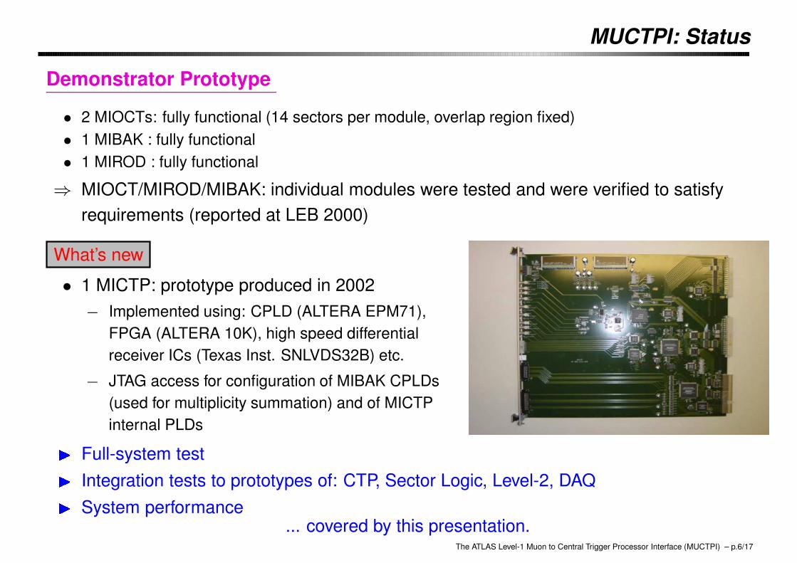
Demonstrator Prototype
• 2 MIOCTs: fully functional (14 sectors per module, overlap region fixed)• 1 MIBAK : fully functional• 1 MIROD : fully functional
⇒ MIOCT/MIROD/MIBAK: individual modules were tested and were verified to satisfyrequirements (reported at LEB 2000)
What’s new
• 1 MICTP: prototype produced in 2002− Implemented using: CPLD (ALTERA EPM71),
FPGA (ALTERA 10K), high speed differentialreceiver ICs (Texas Inst. SNLVDS32B) etc.
− JTAG access for configuration of MIBAK CPLDs(used for multiplicity summation) and of MICTPinternal PLDs� Full-system test� Integration tests to prototypes of: CTP, Sector Logic, Level-2, DAQ� System performance
... covered by this presentation.The ATLAS Level-1 Muon to Central Trigger Processor Interface (MUCTPI) – p.6/17
Full-system Test
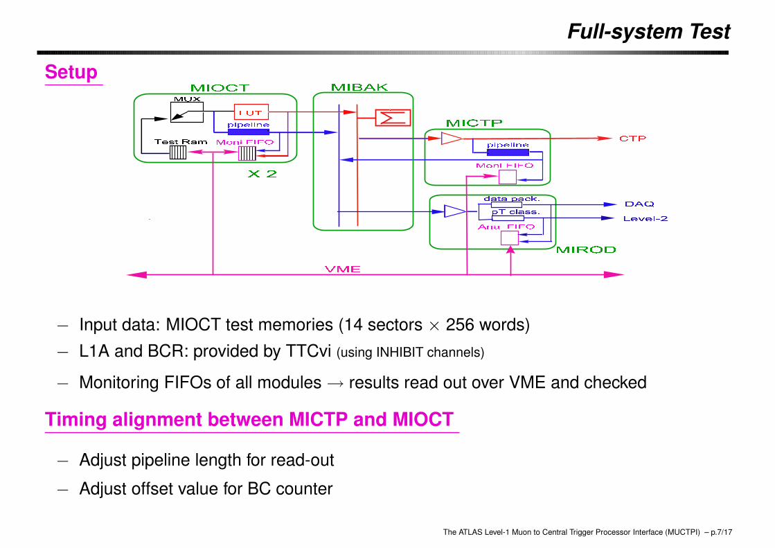
Setup
− Input data: MIOCT test memories (14 sectors × 256 words)− L1A and BCR: provided by TTCvi (using INHIBIT channels)
− Monitoring FIFOs of all modules → results read out over VME and checked
Timing alignment between MICTP and MIOCT
− Adjust pipeline length for read-out
− Adjust offset value for BC counter
The ATLAS Level-1 Muon to Central Trigger Processor Interface (MUCTPI) – p.7/17
Full-system Test -cont’d-
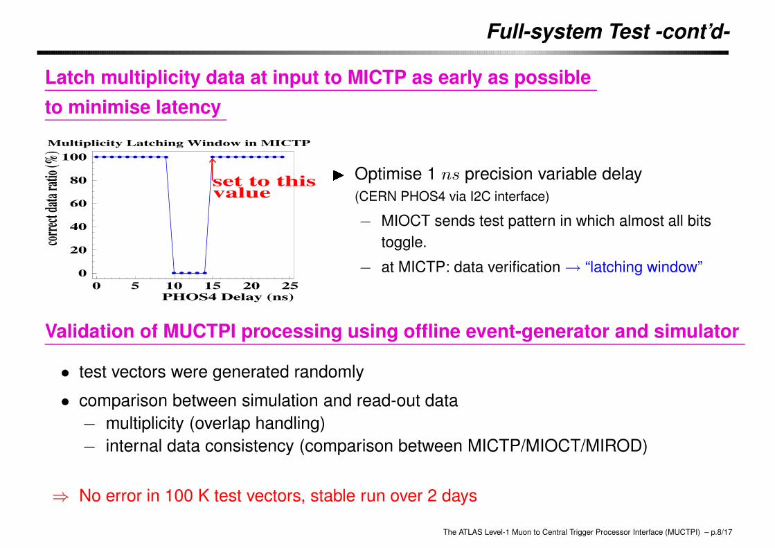
Latch multiplicity data at input to MICTP as early as possibleto minimise latency
Multiplicity Latching Window in MICTP
0
20
40
60
80
100
0 5 10 15 20 25
set to thisvalue
PHOS4 Delay (ns)
correc
t data
ratio
(%) � Optimise 1 ns precision variable delay
(CERN PHOS4 via I2C interface)
− MIOCT sends test pattern in which almost all bitstoggle.
− at MICTP: data verification → “latching window”
Validation of MUCTPI processing using offline event-generator and simulator
• test vectors were generated randomly
• comparison between simulation and read-out data− multiplicity (overlap handling)− internal data consistency (comparison between MICTP/MIOCT/MIROD)
⇒ No error in 100 K test vectors, stable run over 2 days
The ATLAS Level-1 Muon to Central Trigger Processor Interface (MUCTPI) – p.8/17
Trigger Path Connectivity: from Sector Logic
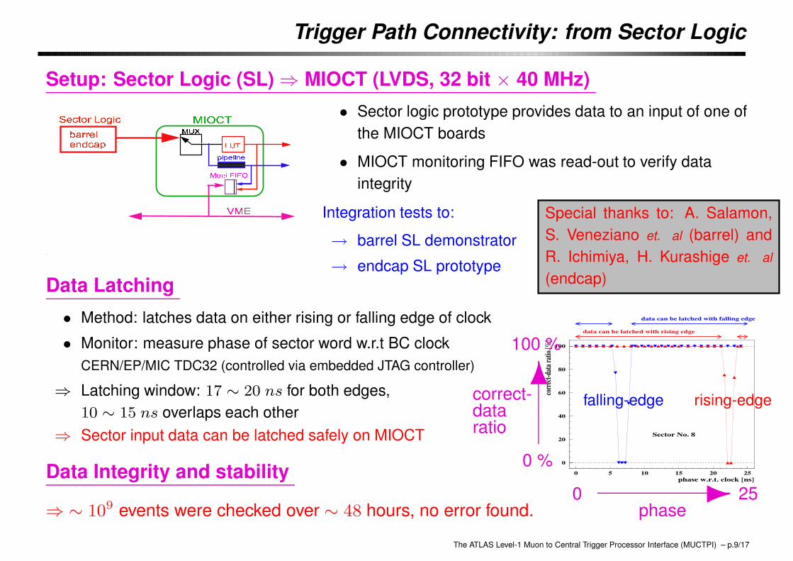
Setup: Sector Logic (SL) ⇒ MIOCT (LVDS, 32 bit × 40 MHz)
12 34 56789 9 9 9 9 9 9 9 9 9 9 9 9 9 9 9 9 99 99 99 99 99 99 99 99 99 99 99 99 99 99 99 99 99 99 99 99 99 99:7; <<<<<<<<<<<<<<<<<<<<<<<<<<<<<<<<<< <<<< <<<< <<<< <<<< <<<< <<<< <<<< <<<< <<<< <<<< <<<< <<<< <<<< <<<< <<<<= > =? @ >A ?<<<<<<<<<<<<<< <<<<<<<<<<<<9999999999 9999999999 9999999999 9999999999 9999999999 9999999999 99999999996B A >CD C E
FGH
IJK KL ML N OP JQRL P STK U TV WP • Sector logic prototype provides data to an input of one of
the MIOCT boards
• MIOCT monitoring FIFO was read-out to verify dataintegrity
Integration tests to:
→ barrel SL demonstrator
→ endcap SL prototype
Special thanks to: A. Salamon,S. Veneziano et. al (barrel) andR. Ichimiya, H. Kurashige et. al
(endcap)Data Latching
• Method: latches data on either rising or falling edge of clock
• Monitor: measure phase of sector word w.r.t BC clockCERN/EP/MIC TDC32 (controlled via embedded JTAG controller)
⇒ Latching window: 17 ∼ 20 ns for both edges,10 ∼ 15 ns overlaps each other
⇒ Sector input data can be latched safely on MIOCT
0
20
40
60
80
100
0 5 10 15 20 25
data can be latched with rising edge
data can be latched with falling edge
Sector No. 8
phase w.r.t. clock [ns]
corre
ct-da
ta ra
tio [%
]
0 25phase-0 %
100 %
6correct-dataratio
falling-edge rising-edge
Data Integrity and stability
⇒ ∼ 109 events were checked over ∼ 48 hours, no error found.
The ATLAS Level-1 Muon to Central Trigger Processor Interface (MUCTPI) – p.9/17

Trigger Path Connectivity: to CTP
Setup: MICTP ⇒ CTP demonstrator (ECL differential, 18 bit × 40 MHz)
PPqCTPD
� ��
��MUCTPI
• CTP demonstrator (CTPD): 32 bit input and 32 trigger items(final design: 160 bit inputs and 96 trigger items; CTPD was built 6 years ago to prove the principle)
multiplicity data latching by CTPD
X Phase: measured in steps of 1.5 ns, latching window was obtained→ latch as early as possible to minimise latencyX Data verification: no error, stable over a few hours
The ATLAS Level-1 Muon to Central Trigger Processor Interface (MUCTPI) – p.10/17
Trigger Path Connectivity: to CTP -cont’d-
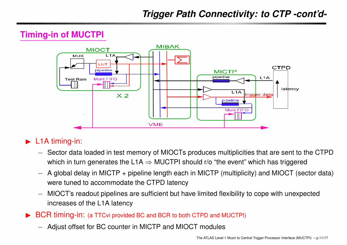
Timing-in of MUCTPI
� L1A timing-in:− Sector data loaded in test memory of MIOCTs produces multiplicities that are sent to the CTPD
which in turn generates the L1A ⇒ MUCTPI should r/o “the event” which has triggered
− A global delay in MICTP + pipeline length each in MICTP (multiplicity) and MIOCT (sector data)were tuned to accommodate the CTPD latency
− MIOCT’s readout pipelines are sufficient but have limited flexibility to cope with unexpectedincreases of the L1A latency� BCR timing-in: (a TTCvi provided BC and BCR to both CTPD and MUCTPI)
− Adjust offset for BC counter in MICTP and MIOCT modulesThe ATLAS Level-1 Muon to Central Trigger Processor Interface (MUCTPI) – p.11/17
Read-out Path Connectivity: to Level-2
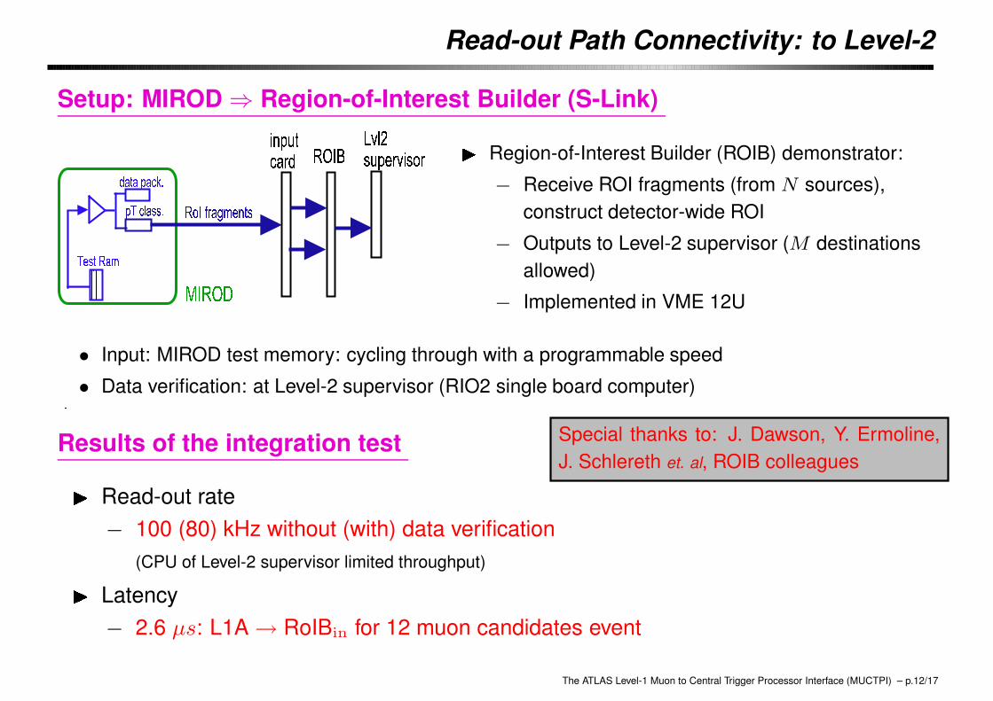
Setup: MIROD ⇒ Region-of-Interest Builder (S-Link)
0 Region-of-Interest Builder (ROIB) demonstrator:
− Receive ROI fragments (from N sources),construct detector-wide ROI
− Outputs to Level-2 supervisor (M destinationsallowed)
− Implemented in VME 12U
• Input: MIROD test memory: cycling through with a programmable speed
• Data verification: at Level-2 supervisor (RIO2 single board computer)
Results of the integration test Special thanks to: J. Dawson, Y. Ermoline,J. Schlereth et. al, ROIB colleagues� Read-out rate
− 100 (80) kHz without (with) data verification(CPU of Level-2 supervisor limited throughput)� Latency
− 2.6 µs: L1A → RoIBin for 12 muon candidates event
The ATLAS Level-1 Muon to Central Trigger Processor Interface (MUCTPI) – p.12/17
Read-out Path Connectivity: to Read-out System (ROS)
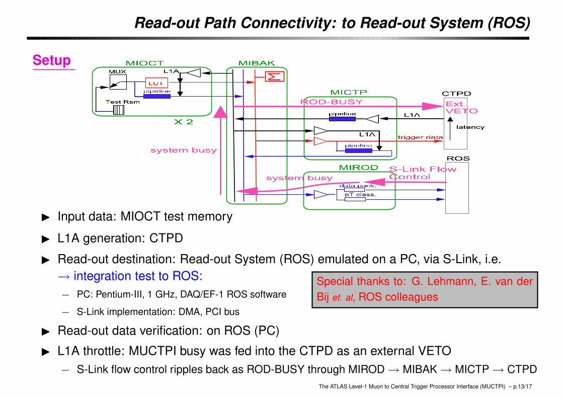
Setup
� Input data: MIOCT test memory
Special thanks to: G. Lehmann, E. van derBij et. al, ROS colleagues
� L1A generation: CTPD� Read-out destination: Read-out System (ROS) emulated on a PC, via S-Link, i.e.→ integration test to ROS:− PC: Pentium-III, 1 GHz, DAQ/EF-1 ROS software
− S-Link implementation: DMA, PCI bus� Read-out data verification: on ROS (PC)� L1A throttle: MUCTPI busy was fed into the CTPD as an external VETO− S-Link flow control ripples back as ROD-BUSY through MIROD → MIBAK → MICTP → CTPD
The ATLAS Level-1 Muon to Central Trigger Processor Interface (MUCTPI) – p.13/17
Performance: Level-1 Trigger Latency
MIOCT internal BCK
MIOCT input (from SL)
-10ns
0ns
MIOCT internal LUT input
+25ns +50ns
+32ns
+75ns +100ns
+79ns
MIOCT MUL1-1 output to MIBAK
+102ns
MICTP MUL1-1 input from MIBAK
+81ns +106ns
+115ns
MICTP internal BCKM
MICTP MUL1-1 output to CTPD
+130ns
CTPD input (3m of flat cable)
+135ns
+187ns
CTPD internal BCK for VLPL
CTPD L1A output
MUCTPI + CTPD: Level-1 Trigger Latency
�-125 ns
MIOCT IN from SL
MICTP mult IN from MIBAK
MICTP internal clockMICTP mult OUT
MIOCT LUT INMIBAK mult IN from MIOCT j���:
MICTP latching multiplicityphase was optimised to minimiselatency
�-55 ns
CTPD mult INCTPD internal clock
CTPD L1A OUT
j - CTPD latching multiplicityphase was optimised to minimiselatency
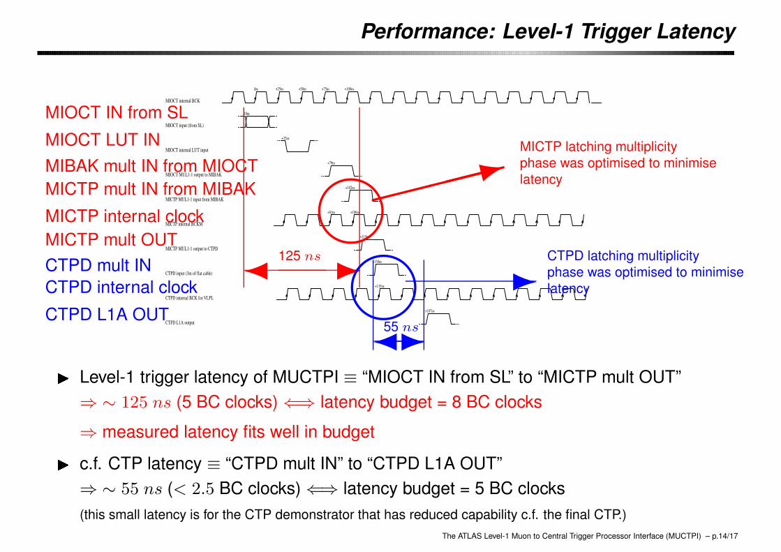
X Level-1 trigger latency of MUCTPI ≡ “MIOCT IN from SL” to “MICTP mult OUT”⇒ ∼ 125 ns (5 BC clocks) ⇐⇒ latency budget = 8 BC clocks
⇒ measured latency fits well in budget
X c.f. CTP latency ≡ “CTPD mult IN” to “CTPD L1A OUT”⇒ ∼ 55 ns (< 2.5 BC clocks) ⇐⇒ latency budget = 5 BC clocks(this small latency is for the CTP demonstrator that has reduced capability c.f. the final CTP.)
The ATLAS Level-1 Muon to Central Trigger Processor Interface (MUCTPI) – p.14/17

Performance: Read-out Latency
� -1.8 µs
S-Link ready at MIROD OUT
L1A at CTP OUT
DAQ branch of MIROD
3 muon candidate event
X Read-out latency
• DAQ branch: 1.8 (2.5) µs for 3 (56) µ candidates event
• Level-2 branch: 1.8 (3.9) µs for 3 (56) µ candidates event− For Level-2 br., MIROD sorts candidates in pT , send up to 12 (max. 16) highest-pT
candidates as RoI information to Level-2− For DAQ br., processing in MIROD is simpler
⇒ NOTE: Numbers of µ candidates presented here are much larger than expected innormal operation.
⇒ Latency: 2 ∼ 3 µs for a few µ candidates event in absence of queueing effects→ fits well in budget
The ATLAS Level-1 Muon to Central Trigger Processor Interface (MUCTPI) – p.15/17

Performance: Read-out Rate
MUCTPI Readout over S-Link
8090
100
200
300
400500600700800900
1000
2000
0 5 10 15 20 25 30
75 kHz
100 kHz
PC emulating ROS w/o data verification
PC emulating ROS w/ data verification
SLIDAD
number of muon candidates
max
imum
rea
dout
rat
e (k
Hz)
� Back-pressure VETO mechanism worked
� Data verification at ROS (PC) showed no error⇒ ran stably w/o any error over 24 hours
� Maximum read-out rate: (DAQ branch)
• SLIDAD (S-Link Infinite Data Drain):∼ 1200 kHz for 1 µ event∼ 650 kHz for 30 µ event
⇒ MUCTPI intrinsic read-out capability
• PC emulating ROS:∼ 140 kHz for 1 µ event∼ 130 kHz for 30 µ event
⇒ PC emulating ROS limited the read-outrate in the current setup
The ATLAS Level-1 Muon to Central Trigger Processor Interface (MUCTPI) – p.16/17
Summary
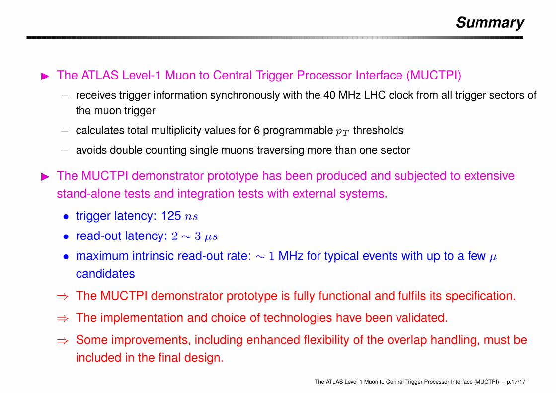
� The ATLAS Level-1 Muon to Central Trigger Processor Interface (MUCTPI)
− receives trigger information synchronously with the 40 MHz LHC clock from all trigger sectors ofthe muon trigger
− calculates total multiplicity values for 6 programmable pT thresholds
− avoids double counting single muons traversing more than one sector
� The MUCTPI demonstrator prototype has been produced and subjected to extensivestand-alone tests and integration tests with external systems.
• trigger latency: 125 ns
• read-out latency: 2 ∼ 3 µs
• maximum intrinsic read-out rate: ∼ 1 MHz for typical events with up to a few µ
candidates
⇒ The MUCTPI demonstrator prototype is fully functional and fulfils its specification.
⇒ The implementation and choice of technologies have been validated.
⇒ Some improvements, including enhanced flexibility of the overlap handling, must beincluded in the final design.
The ATLAS Level-1 Muon to Central Trigger Processor Interface (MUCTPI) – p.17/17