the basic asphalt recycling manual (barm) - construction
TRANSCRIPT

A S P H A L T R E C Y C L I N G A N D R E C L A I M I N G A S S O C I A T I O N
Asphalt Recycling
Manual
Basic
U.S. Departmentof Transportation
Federal HighwayAdministration
Cover Photo: Downtown Houston, Texas

DISCLAIMERThe Asphalt Recycling and Reclaiming Association (ARRA) have taken every care and precaution during the preparation of this manual, recognizing that the “State-of-the-Art” of in-place asphalt recycling is continually evolving. Mature engineering judgement and skill mustbe used to properly apply the information, guidelines, and principles contained within this manual, taking into account existing conditions, locally available materials, equipment, andexpertise. ARRA can accept no responsibility for any defects or failures in the performance ofany recycled materials, pavement structures, analysis or designs resulting from an inappropriateapplication or use of information contained within this manual.
The photographs, drawings, and/or processes used in this manual are for illustration purposes only.They do not imply preferential endorsement of any particular make, model, or process by ARRA.
B
Copyright © 2001, ARRA. All Rights Reserved.
No part of this work may be reproduced in any form,
or by any means, without the permission of ARRA.
PRINTED IN THE USA

Forward
FORWARD
ARRA has published this first edition of the Basic Asphalt Recycling Manual (BARM).The BARM was prepared by Mr. Leonard Dunn, P.Eng. under contract with ARRA. Dr. Stephen Cross, P.E. (University of Kansas) was subsequently retained to assist in thepreparation of Chapters 15 to 17, on Cold Recycling.
A steering committee consisting of Mr. Brian Hansen (Dustrol, Inc.), Mr. StephenDamp (Miller Paving Limited), and Mr. Todd Casey (Base Construction Co., Ltd.)directed and oversaw the preparation of the BARM.
Mr. Fred Miller of the ARRA office undertook the initial editing of the BARM.
Mr. John Huffman, P.E. (Brown & Brown, Inc.) was an invaluable resource during the initial preparation and acted as the final editor of the BARM.
Valuable input and advice were received from the general ARRA membership. In particular, the assistance of the following ARRA members is greatly appreciated.
■ Mr. Angelo Benedetti (Angelo Benedetti, Inc.)■ Mr. Todd Casey (Base Construction Co., Ltd.)■ Mr. Kenneth Damgaard (Arizona Department of Transportation)■ Mr. Stephen Damp (Miller Paving Limited)■ Mr. Charles Dane (Slurry Pavers, Inc.)■ Mr. Barry Dunn (Viking Construction Inc.)■ Mr. John Emery, P.Eng. (John Emery Geotechnical Engineering Ltd.)■ Mr. Ken Fyvie (Terra Engineering Ltd.)■ Mr. Jim Halverson (J.A. James Construction Company)■ Mr. Brian Hansen (Dustrol, Inc.)■ Mr. Terry Hauer (Caterpillar Paving Products, Inc.)■ Mr. John Huffman, P.E. (Brown & Brown)■ Mr. Ed Kearney, P.E. (Gorman Bros., Inc.)■ Mr. Brian Mountjoy, P.Eng. (Hard Rock Paving Company Limited)■ Mr. Stuart Murray (Wirtgen America, Inc.)■ Mr. Bill Petersmeyer (ARC Asphalt Recycling Corporation)■ Mr. Michael Polak (E. J. Breneman, Inc.)■ Mr. John Rathbun (Cutler Repaving, Inc.)■ Mr. Dennis Ryan (Copperstate Emulsions)■ Dr. Tom Siddon, P.Eng. (Martec Recycling Corporation)■ Mr. Bryan Vuillaume (Pallette Stone Corporation)■ Mr. Phillip Wise (Hamm Compactors Inc.)
C

Contents
ECONTENTS
BASIC ASPHALT RECYCLING MANUAL
1
27
35
TABLE OF CONTENTS
PART 1: INTRODUCTION, RECYCLING OVERVIEW, AND PROJECT EVALUATION
CHAPTER 1: INTRODUCTION
1.1 Background . . . . . . . . . . . . . . . . . . . . . . . . . . . . . . . . . . . . . . . . . . . . . . . .21.2 Asphalt Recycling Methods . . . . . . . . . . . . . . . . . . . . . . . . . . . . . . . . . . . .41.3 Cold Planing (CP) . . . . . . . . . . . . . . . . . . . . . . . . . . . . . . . . . . . . . . . . . . . .51.4 Hot Recycling . . . . . . . . . . . . . . . . . . . . . . . . . . . . . . . . . . . . . . . . . . . . . . .71.5 Hot In-Place Recycling (HIR) . . . . . . . . . . . . . . . . . . . . . . . . . . . . . . . . . . .91.6 Full Depth Reclamation (FDR) . . . . . . . . . . . . . . . . . . . . . . . . . . . . . . . . .161.7 Cold Recycling (CP) . . . . . . . . . . . . . . . . . . . . . . . . . . . . . . . . . . . . . . . . .19
CHAPTER 2: REHABILITATION STRATEGIES
2.1 Pavement Maintenance . . . . . . . . . . . . . . . . . . . . . . . . . . . . . . . . . . . . . . .282.2 Pavement Rehabilitation . . . . . . . . . . . . . . . . . . . . . . . . . . . . . . . . . . . . . .302.3 Pavement Reconstruction . . . . . . . . . . . . . . . . . . . . . . . . . . . . . . . . . . . . .33
CHAPTER 3: PROJECT EVALUATION
3.1 Pavement Assessment . . . . . . . . . . . . . . . . . . . . . . . . . . . . . . . . . . . . . . . .353.1.1 Surface Defects . . . . . . . . . . . . . . . . . . . . . . . . . . . . . . . . . . . . . . . . . . . .363.1.2 Deformations . . . . . . . . . . . . . . . . . . . . . . . . . . . . . . . . . . . . . . . . . . . . . .383.1.3 Cracking . . . . . . . . . . . . . . . . . . . . . . . . . . . . . . . . . . . . . . . . . . . . . . . . . .393.1.4 Maintenance Activities . . . . . . . . . . . . . . . . . . . . . . . . . . . . . . . . . . . . . . .413.1.5 Problem Base/Subgrades . . . . . . . . . . . . . . . . . . . . . . . . . . . . . . . . . . . . . .423.1.6 Ride Quality . . . . . . . . . . . . . . . . . . . . . . . . . . . . . . . . . . . . . . . . . . . . . . .433.1.7 Safety Evaluation . . . . . . . . . . . . . . . . . . . . . . . . . . . . . . . . . . . . . . . . . . .433.2 Historic Information Review . . . . . . . . . . . . . . . . . . . . . . . . . . . . . . . . . . .433.3 Pavement Properties Assessment . . . . . . . . . . . . . . . . . . . . . . . . . . . . . . . .443.3.1 Roughness . . . . . . . . . . . . . . . . . . . . . . . . . . . . . . . . . . . . . . . . . . . . . . . .443.3.2 Rutting . . . . . . . . . . . . . . . . . . . . . . . . . . . . . . . . . . . . . . . . . . . . . . . . . . .453.3.3 Friction Number . . . . . . . . . . . . . . . . . . . . . . . . . . . . . . . . . . . . . . . . . . . .453.3.4 Strength . . . . . . . . . . . . . . . . . . . . . . . . . . . . . . . . . . . . . . . . . . . . . . . . . .463.3.5 Materials Properties . . . . . . . . . . . . . . . . . . . . . . . . . . . . . . . . . . . . . . . . .473.4 Distress Evaluation . . . . . . . . . . . . . . . . . . . . . . . . . . . . . . . . . . . . . . . . . .483.5 Preliminary Rehabilitation Selection . . . . . . . . . . . . . . . . . . . . . . . . . . . . .493.6 Economic Analysis . . . . . . . . . . . . . . . . . . . . . . . . . . . . . . . . . . . . . . . . . .51

F CONTENTS
65
81
101
115
55
PART 2: HOT IN-PLACE RECYCLING (HIR)
CHAPTER 4: HOT IN-PLACE RECYCLING - DETAILED PROJECT ANALYSIS
4.0 Hot In-Place Recycling Rehabilitation . . . . . . . . . . . . . . . . . . . . . . . . . . . . . . . . . . . .554.1 Historic Information Assessment . . . . . . . . . . . . . . . . . . . . . . . . . . . . . . . . . . . . . . . .564.2 Pavement Assessment . . . . . . . . . . . . . . . . . . . . . . . . . . . . . . . . . . . . . . . . . . . . . . . . .574.3 Structural Capacity Assessment . . . . . . . . . . . . . . . . . . . . . . . . . . . . . . . . . . . . . . . . .594.4 Material Properties Assessment . . . . . . . . . . . . . . . . . . . . . . . . . . . . . . . . . . . . . . . . .604.5 Geometric Assessment . . . . . . . . . . . . . . . . . . . . . . . . . . . . . . . . . . . . . . . . . . . . . . . .614.6 Traffic Assessment . . . . . . . . . . . . . . . . . . . . . . . . . . . . . . . . . . . . . . . . . . . . . . . . . . .634.7 Constructability Assessment . . . . . . . . . . . . . . . . . . . . . . . . . . . . . . . . . . . . . . . . . . . .634.8 Environmental Implications . . . . . . . . . . . . . . . . . . . . . . . . . . . . . . . . . . . . . . . . . . . .644.9 Economic Assessment . . . . . . . . . . . . . . . . . . . . . . . . . . . . . . . . . . . . . . . . . . . . . . . .64
CHAPTER 5: HOT IN-PLACE RECYCLING MIX DESIGN
5.1 Asphalt Binder Rejuvenation . . . . . . . . . . . . . . . . . . . . . . . . . . . . . . . . . . . . . . . . . . .665.2 Mix Design Process . . . . . . . . . . . . . . . . . . . . . . . . . . . . . . . . . . . . . . . . . . . . . . . . . .685.2.1 Blending Charts . . . . . . . . . . . . . . . . . . . . . . . . . . . . . . . . . . . . . . . . . . . . . . . . . . . . .685.2.2 Traditional/Comprehensive . . . . . . . . . . . . . . . . . . . . . . . . . . . . . . . . . . . . . . . . . . . . .705.2.3 Superpave . . . . . . . . . . . . . . . . . . . . . . . . . . . . . . . . . . . . . . . . . . . . . . . . . . . . . . . . . .76
CHAPTER 6: HOT IN-PLACE RECYCLING CONSTRUCTION
6.1 Surface Recycling . . . . . . . . . . . . . . . . . . . . . . . . . . . . . . . . . . . . . . . . . . . . . . . . . . .816.2 Remixing . . . . . . . . . . . . . . . . . . . . . . . . . . . . . . . . . . . . . . . . . . . . . . . . . . . . . . . . . .896.3 Repaving . . . . . . . . . . . . . . . . . . . . . . . . . . . . . . . . . . . . . . . . . . . . . . . . . . . . . . . . . .97
CHAPTER 7: HOT IN-PLACE RECYCLING SPECIFICATIONS AND INSPECTION
7.1 Method Specifications . . . . . . . . . . . . . . . . . . . . . . . . . . . . . . . . . . . . . . . . . . . . . . .1037.2 End Result Specifications . . . . . . . . . . . . . . . . . . . . . . . . . . . . . . . . . . . . . . . . . . . .1067.3 Specifications Limits . . . . . . . . . . . . . . . . . . . . . . . . . . . . . . . . . . . . . . . . . . . . . . . .1087.4 Inspection, Quality Control and Quality Assurance . . . . . . . . . . . . . . . . . . . . . . . . .110
PART 3: COLD PLANING (CP)
CHAPTER 8: COLD PLANING CONSTRUCTION
8.0 Cold Planing Rehabilitation . . . . . . . . . . . . . . . . . . . . . . . . . . . . . . . . . . . . . . . . . . .1158.1 CP Detailed Project Analysis . . . . . . . . . . . . . . . . . . . . . . . . . . . . . . . . . . . . . . . . . .1158.2 CP Equipment . . . . . . . . . . . . . . . . . . . . . . . . . . . . . . . . . . . . . . . . . . . . . . . . . . . . .1168.3 Preparation and Planning . . . . . . . . . . . . . . . . . . . . . . . . . . . . . . . . . . . . . . . . . . . . .1238.4 CP Micro Milling . . . . . . . . . . . . . . . . . . . . . . . . . . . . . . . . . . . . . . . . . . . . . . . . . . .1248.5 Safety Warnings . . . . . . . . . . . . . . . . . . . . . . . . . . . . . . . . . . . . . . . . . . . . . . . . . . . .124

GCONTENTS
127
133
143
157
179
CHAPTER 9: COLD PLANING SPECIFICATIONS AND INSPECTION
9.1 Standard Specifications . . . . . . . . . . . . . . . . . . . . . . . . . . . . . . . . . . . . . . . . . . . . . . .1279.2 Specifications Limits . . . . . . . . . . . . . . . . . . . . . . . . . . . . . . . . . . . . . . . . . . . . . . . .1309.3 Inspection, Quality Control and Quality Assurance . . . . . . . . . . . . . . . . . . . . . . . . . .132
PART 4: FULL DEPTH RECLAMATION (FDR)
CHAPTER 10: FULL DEPTH RECLAMATION - DETAILED PROJECT ANALYSIS
10.0 Full Depth Reclamation Rehabilitation . . . . . . . . . . . . . . . . . . . . . . . . . . . . . . . . . . .13310.1 Historic Information Assessment . . . . . . . . . . . . . . . . . . . . . . . . . . . . . . . . . . . . . . . .13410.2 Pavement Assessment . . . . . . . . . . . . . . . . . . . . . . . . . . . . . . . . . . . . . . . . . . . . . . . .13510.3 Structural Capacity Assessment . . . . . . . . . . . . . . . . . . . . . . . . . . . . . . . . . . . . . . . . .13610.4 Material Properties Assessment . . . . . . . . . . . . . . . . . . . . . . . . . . . . . . . . . . . . . . . . .13710.5 Geometric Assessment . . . . . . . . . . . . . . . . . . . . . . . . . . . . . . . . . . . . . . . . . . . . . . .13810.6 Traffic Assessment . . . . . . . . . . . . . . . . . . . . . . . . . . . . . . . . . . . . . . . . . . . . . . . . . .13910.7 Constructability Assessment . . . . . . . . . . . . . . . . . . . . . . . . . . . . . . . . . . . . . . . . . . .14010.8 Environmental Implications . . . . . . . . . . . . . . . . . . . . . . . . . . . . . . . . . . . . . . . . . . . .14010.9 Economic Assessment . . . . . . . . . . . . . . . . . . . . . . . . . . . . . . . . . . . . . . . . . . . . . . . .141
CHAPTER 11: FULL DEPTH RECLAMATION - MIX DESIGN
11.1 Mechanical Stabilization Mix Design . . . . . . . . . . . . . . . . . . . . . . . . . . . . . . . . . . . .14611.2 Chemical Stabilization Mix Design . . . . . . . . . . . . . . . . . . . . . . . . . . . . . . . . . . . . . .14811.3 Bituminous Stabilization Mix Design . . . . . . . . . . . . . . . . . . . . . . . . . . . . . . . . . . . .15011.4 Combined Stabilization Mix Design . . . . . . . . . . . . . . . . . . . . . . . . . . . . . . . . . . . . .154
CHAPTER 12: FULL DEPTH RECLAMATION - CONSTRUCTION
12.1 FDR Equipment . . . . . . . . . . . . . . . . . . . . . . . . . . . . . . . . . . . . . . . . . . . . . . . . . . . .15912.2 Preparation and Planning . . . . . . . . . . . . . . . . . . . . . . . . . . . . . . . . . . . . . . . . . . . . . .16412.3 Pulverization . . . . . . . . . . . . . . . . . . . . . . . . . . . . . . . . . . . . . . . . . . . . . . . . . . . . . . .16712.4 Mixing and Placement . . . . . . . . . . . . . . . . . . . . . . . . . . . . . . . . . . . . . . . . . . . . . . . .17112.5 Stabilizing Agent Addition . . . . . . . . . . . . . . . . . . . . . . . . . . . . . . . . . . . . . . . . . . . .17212.6 Compaction . . . . . . . . . . . . . . . . . . . . . . . . . . . . . . . . . . . . . . . . . . . . . . . . . . . . . . . .17412.7 Curing . . . . . . . . . . . . . . . . . . . . . . . . . . . . . . . . . . . . . . . . . . . . . . . . . . . . . . . . . . . .17512.8 Wearing Surface . . . . . . . . . . . . . . . . . . . . . . . . . . . . . . . . . . . . . . . . . . . . . . . . . . . .177
CHAPTER 13: FULL DEPTH RECLAMATION - SPECIFICATIONS AND INSPECTION
13.1 Standard Specifications . . . . . . . . . . . . . . . . . . . . . . . . . . . . . . . . . . . . . . . . . . . . . . .17913.2 Specifications Limits . . . . . . . . . . . . . . . . . . . . . . . . . . . . . . . . . . . . . . . . . . . . . . . .18413.3 Inspection, Quality Control and Quality Assurance . . . . . . . . . . . . . . . . . . . . . . . . . .187

H CONTENTS
191
203
PART 5: COLD RECYCLING (CR)
CHAPTER 14: COLD RECYCLING - DETAILED PROJECT ANALYSIS
14.0 Cold Recycling Rehabilitation . . . . . . . . . . . . . . . . . . . . . . . . . . . . . . . . . . . . . . .19114.1 Historic Information Assessment . . . . . . . . . . . . . . . . . . . . . . . . . . . . . . . . . . . . .19214.2 Pavement Assessment . . . . . . . . . . . . . . . . . . . . . . . . . . . . . . . . . . . . . . . . . . . . .19314.3 Structural Capacity Assessment . . . . . . . . . . . . . . . . . . . . . . . . . . . . . . . . . . . . . .19514.4 Material Properties Assessment . . . . . . . . . . . . . . . . . . . . . . . . . . . . . . . . . . . . . .19714.5 Geometric Assessment . . . . . . . . . . . . . . . . . . . . . . . . . . . . . . . . . . . . . . . . . . . .19814.6 Traffic Assessment . . . . . . . . . . . . . . . . . . . . . . . . . . . . . . . . . . . . . . . . . . . . . . .19914.7 Constructability Assessment . . . . . . . . . . . . . . . . . . . . . . . . . . . . . . . . . . . . . . . .20014.8 Environmental Implications . . . . . . . . . . . . . . . . . . . . . . . . . . . . . . . . . . . . . . . . .20114.9 Economic Assessment . . . . . . . . . . . . . . . . . . . . . . . . . . . . . . . . . . . . . . . . . . . . .201
CHAPTER 15: COLD RECYCLING - MIX DESIGN
15.1 Sampling Existing Pavement . . . . . . . . . . . . . . . . . . . . . . . . . . . . . . . . . . . . . . . .20415.2 Determination of RAP Properties . . . . . . . . . . . . . . . . . . . . . . . . . . . . . . . . . . . .20515.3 Select Amount and Gradation of New Aggregate . . . . . . . . . . . . . . . . . . . . . . . . .20615.4 Estimate New Recycling Additive Demand . . . . . . . . . . . . . . . . . . . . . . . . . . . . .20815.5 Selection of Recycling Additive . . . . . . . . . . . . . . . . . . . . . . . . . . . . . . . . . . . . .20815.5.1 Asphalt Emulsions . . . . . . . . . . . . . . . . . . . . . . . . . . . . . . . . . . . . . . . . . . . . . . .20815.5.2 Recycling Agents . . . . . . . . . . . . . . . . . . . . . . . . . . . . . . . . . . . . . . . . . . . . . . . .20915.5.3 Cutback Asphalts . . . . . . . . . . . . . . . . . . . . . . . . . . . . . . . . . . . . . . . . . . . . . . . .21015.5.4 Foamed Asphalts . . . . . . . . . . . . . . . . . . . . . . . . . . . . . . . . . . . . . . . . . . . . . . . . .21015.5.5 Chemical Additives . . . . . . . . . . . . . . . . . . . . . . . . . . . . . . . . . . . . . . . . . . . . . . .21015.6 Determine Pre-Mix Moisture Content for Coating . . . . . . . . . . . . . . . . . . . . . . . .21015.7 Trial Mixtures . . . . . . . . . . . . . . . . . . . . . . . . . . . . . . . . . . . . . . . . . . . . . . . . . . .21115.7.1 Batching . . . . . . . . . . . . . . . . . . . . . . . . . . . . . . . . . . . . . . . . . . . . . . . . . . . . . . .21115.7.2 Mixing . . . . . . . . . . . . . . . . . . . . . . . . . . . . . . . . . . . . . . . . . . . . . . . . . . . . . . . .21115.7.3 Compaction . . . . . . . . . . . . . . . . . . . . . . . . . . . . . . . . . . . . . . . . . . . . . . . . . . . . .21115.7.4 Curing . . . . . . . . . . . . . . . . . . . . . . . . . . . . . . . . . . . . . . . . . . . . . . . . . . . . . . . . .21215.7.5 Strength Testing . . . . . . . . . . . . . . . . . . . . . . . . . . . . . . . . . . . . . . . . . . . . . . . . .21315.8 Establish Job Mix Formula . . . . . . . . . . . . . . . . . . . . . . . . . . . . . . . . . . . . . . . . .21415.9 Field Adjustments . . . . . . . . . . . . . . . . . . . . . . . . . . . . . . . . . . . . . . . . . . . . . . . .214

ICONTENTS
215
229
CHAPTER 16: COLD RECYCLING - CONSTRUCTION
16.1 Cold In-Place Recycling Methods . . . . . . . . . . . . . . . . . . . . . . . . . . . . . . . . . . . .21716.1.1 Preparation of Construction Area . . . . . . . . . . . . . . . . . . . . . . . . . . . . . . . . . . . .21816.1.2 Recycling Trains . . . . . . . . . . . . . . . . . . . . . . . . . . . . . . . . . . . . . . . . . . . . . . . . .21816.1.2.1 Single Unit Trains . . . . . . . . . . . . . . . . . . . . . . . . . . . . . . . . . . . . . . . . . . . . . . . .21816.1.2.2 Two-Unit Trains . . . . . . . . . . . . . . . . . . . . . . . . . . . . . . . . . . . . . . . . . . . . . . . . .21916.1.2.3 Multi-Unit Trains . . . . . . . . . . . . . . . . . . . . . . . . . . . . . . . . . . . . . . . . . . . . . . . .22016.1.3 Field Adjustments to the Mix . . . . . . . . . . . . . . . . . . . . . . . . . . . . . . . . . . . . . . .22116.1.4 Laydown and Compaction . . . . . . . . . . . . . . . . . . . . . . . . . . . . . . . . . . . . . . . . . .22216.1.5 Curing . . . . . . . . . . . . . . . . . . . . . . . . . . . . . . . . . . . . . . . . . . . . . . . . . . . . . . . . .22516.1.6 Wearing Surface . . . . . . . . . . . . . . . . . . . . . . . . . . . . . . . . . . . . . . . . . . . . . . . . .22516.2 Cold Central Plant Recycling . . . . . . . . . . . . . . . . . . . . . . . . . . . . . . . . . . . . . . .22616.2.1 Laydown, Aeration and Compaction . . . . . . . . . . . . . . . . . . . . . . . . . . . . . . . . . .227
CHAPTER 17: COLD RECYCLING - SPECIFICATIONS AND INSPECTION
17.1 Quality Control/Quality Assurance . . . . . . . . . . . . . . . . . . . . . . . . . . . . . . . . . . .23017.2 Inspection and Acceptance Issues . . . . . . . . . . . . . . . . . . . . . . . . . . . . . . . . . . . .23017.2.1 RAP Gradation . . . . . . . . . . . . . . . . . . . . . . . . . . . . . . . . . . . . . . . . . . . . . . . . . .23017.2.2 Recycling Additive(s) Sampling . . . . . . . . . . . . . . . . . . . . . . . . . . . . . . . . . . . . .23417.2.3 Moisture Addition . . . . . . . . . . . . . . . . . . . . . . . . . . . . . . . . . . . . . . . . . . . . . . . .23417.2.4 Recycled Mixture Moisture Content . . . . . . . . . . . . . . . . . . . . . . . . . . . . . . . . . .23517.2.5 Recycling Additive Control . . . . . . . . . . . . . . . . . . . . . . . . . . . . . . . . . . . . . . . . .23617.2.6 Compaction Procedures . . . . . . . . . . . . . . . . . . . . . . . . . . . . . . . . . . . . . . . . . . . .23617.2.7 Compacted Mat Density . . . . . . . . . . . . . . . . . . . . . . . . . . . . . . . . . . . . . . . . . . .23717.2.8 Depth of Milling . . . . . . . . . . . . . . . . . . . . . . . . . . . . . . . . . . . . . . . . . . . . . . . . .23917.2.9 Spreading Depth/Cross-Slope . . . . . . . . . . . . . . . . . . . . . . . . . . . . . . . . . . . . . . .23917.2.10 Mixing Equipment Calibration . . . . . . . . . . . . . . . . . . . . . . . . . . . . . . . . . . . . . .23917.3 Guide Specifications . . . . . . . . . . . . . . . . . . . . . . . . . . . . . . . . . . . . . . . . . . . . . .240
PART 6: GLOSSARY OF TERMS . . . . . . . . . . . . . . . . . . . . . . . . . . . . . . . . . . . . . . . . . . . .245
PART 7: BIBLIOGRAPHY . . . . . . . . . . . . . . . . . . . . . . . . . . . . . . . . . . . . . . . . . . . . . . . . . .257
PART 8: GLOSSARY OF ACRONYMS . . . . . . . . . . . . . . . . . . . . . . . . . . . . . . . . . . . . . . . .265

INTRODUCTION
The growing demand on our nation’s roadways over that past couple of decades, decreasingbudgetary funds, and the need to provide a safe, efficient, and cost effective roadway system has led to a dramatic increase in the need to rehabilitate our existing pavements.
The last 25 years has also seen a dramatic growth in asphalt recycling and reclaiming as atechnically and environmentally preferred way of rehabilitating the existing pavements.Asphalt recycling and reclaiming meets all of our societal goals of providing safe, efficientroadways, while at the same time drastically reducing both the environmental impact andenergy (oil) consumption compared to conventional pavement reconstruction.
The Board of Directors of the Asphalt Recycling and Reclaiming Association (ARRA), intheir ongoing commitment of enhancing and expanding the use of asphalt recycling andreclaiming, recognized a need for a “Basic Asphalt Recycling Manual”. The manual wasneeded in order to expose more owners, specifying agencies, consultants, and civil engineeringstudents to the value and current methods of asphalt recycling. To fill that need, this manualwas produced to serve as a handy one-stop reference to those starting out in one of the various forms of asphalt recycling. In addition, it is hoped that this manual will provide additional useful information to those already involved in asphalt recycling.
This manual is not written in such detail so that one could use it to completely evaluate,design, specify, and/or construct an asphalt recycling project. It does however, provideinformation on:
• various asphalt recycling methods
• benefits and performance of asphalt recycling
• procedures for evaluation potential projects
• current mix design philosophies
• construction equipment requirements and methods
• Quality Control/Quality Assurance, inspection and acceptance techniques
• specification requirements
• definitions and terminology
Sufficient information is provided so that a rational decision can be made with respect to thefeasibility and/or cost benefits of asphalt recycling. From that point, detailed design issues willneed to be addressed by those experienced in asphalt recycling techniques prior to the finalproject design, advertising, tendering or letting and construction.
Asphalt recycling provides an additional rehabilitation method for maintaining existing roadways.The benefits of asphalt recycling include:
• reuse and conservation of non-renewable natural resources
• preservation of the environment and reduction in land filling
• energy conservation
• reduction in user delays during construction
1
Chapter 1
INTRODUCTION

• shorter construction periods
• increased level of traffic safety within construction work zone
• preservation of existing roadway geometry and clearances
• corrections to pavement profile and cross-slope
• no disturbance of the subgrade soils unless specifically plannedsuch as for Full Depth Reclamation (FDR)
• improved pavement smoothness
• improved pavement physical properties by modification of existing aggregate gradation, and asphalt binder properties
• mitigation or elimination of reflective cracking with some methods
• improved roadway performance
• cost savings over traditional rehabilitation methods
It is important to recognize that asphalt recycling is a powerful method to rehabilitate pavements.When properly applied, it has long term economic benefits—allowing owner agencies to stretchtheir available funds while providing the traveling public with a safe and reliable driving surface.
It is also important to recognize that, although asphalt recycling technology and methods hasadvanced, not all roadways are appropriate candidates for asphalt recycling. With the almost endlesssupply of roadways needing rehabilitation, it would be a disservice to the public and the industryto use poor judgement in attempting an inappropriate recycling project. Hopefully, with this manual and the advice of those experienced in asphalt recycling, only projects that are suitablecandidates will be undertaken.
The primary focus of the manual is on the in-place and cold recycling of asphalt pavements. Hot recycling of asphalt pavements through various types of asphalt plants is a well establishedrecycling method. There is a wide variety of information on the subject available from well established sources and therefore has not been covered in any detail in this manual.
1.1 BACKGROUNDPopulation growth and economic development have resulted in an extensive network of asphaltpaved roadways in the last 50 to 70 years. Many thousand of miles (kilometers) were constructedto meet the demands of increased traffic and the majority of these roads are near/at/or past the endof their original design life.
When the roadway network was rapidly expanding, the initial construction cost was the mostimportant issue, with little or no attention being paid to the ongoing maintenance costs. However,as the roadway network has matured, as the traffic volume and gross vehicle weights haveincreased, and as funds have become more tightly budgeted, increased emphasis has been placedon preventive maintenance and preservation of the existing roadways. In many jurisdictions, thefunds available have not been able to keep pace with the increased preventive maintenance andpreservation costs as the roadway network aged. This has resulted in a significant reduction inthe condition and the level of service provided by the roadways within the network. This has inturn resulted in increased overall preventive maintenance and more expensiverehabilitation/reconstruction costs.
2 INTRODUCTION

It is well recognized that a sound infrastructure, including roadways, is required for a good econ-omy with an adequate level of growth. Studies have indicated that if a roadway is maintained, atan acceptable level of service, it will ultimately cost the owner less. A World Bank study indi-cates that each $1.00 expended at the first 40 percent drop in roadway quality will result in a sav-ings of $3.00 to $4.00 compared to the expenditure which would be required at the 80 percentdrop in quality, as indicated in Figure 1-1.
Since funding for preventive maintenance, preservation, rehabilitation, and reconstruction ofroadways will have to compete with other demands on the public purse, innovation is required inorder to do more with less. Asphalt recycling is one way of increasing the effectiveness of exist-ing budgets in order to maintain, preserve, rehabilitate and reconstruct more miles (kilometers) ofroadway for each dollar spent.
Asphalt recycling is not a new concept. Cold recycling/rehabilitation of roadways with asphaltbinders dates to the early 1900’s. The first documented case of asphalt recycling, in the form ofHot In-Place Recycling (HIR), was reported in the literature of the 1930’s. However, only mod-erate advancements in asphalt recycling technology and equipment occurred until the mid 1970’s
Two events of the 1970’s rekindled the interest in asphalt recycling which has resulted in its world-wide use today. The petroleum crisis of the early 1970’s and the development and introduction in1975 of large scale cold planing equipment, complete with easily replaceable tungsten carbidemilling tools, were the catalyst for renewed interest in asphalt recycling. Since that time, theequipment manufacturing and construction industries have been proactive in the development ofasphalt recycling methods and technologies which have advanced exponentially in the last 25 years.
3INTRODUCTION
75% Time – 1st 40%Drop in Quality
12% Time – 2nd 40%Drop in Quality
By Recycling atThis Point, Pavement
Life is Extended
RecycledPavement
TotalFailure
Pav
emen
t C
on
dit
ion
Time (Years)
Figure 1-1: Pavement deterioration and recycling rehabilitation vs. time

Society has become increasingly aware of the effects of all types of development on the environ-ment. Many countries have already enacted legislation which requires that certain percentages ofmaterials, particularly the ones used in roadway construction and rehabilitation, must be recycledor include recycled materials. By demonstrating the technical viability, the savings in energy andnon-renewable natural resource (crude oil and granular materials) and the cost savings associatedwith asphalt recycling, progress towards one of society’s goals of environmentally responsibleconstruction processes will be achieved. It is noted, that asphalt pavements are presently the mostcommonly recycled material in North America.
1.2 ASPHALT RECYCLING METHODSFive broad categories have been defined by ARRA to describe the various asphalt recycling methods. These categories are:
• Cold Planing (CP)
• Hot Recycling
• Hot In-Place Recycling (HIR)
• Cold Recycling (CR)
• Full Depth Reclamation (FDR)
Within these five broad categories of asphalt recycling, there are a number of sub-categorieswhich further define asphalt recycling. These include:
• HIR
- Surface Recycling (Resurfacing)
- Remixing
- Repaving
• CR
- Cold In-Place Recycling (CIR)
- Cold Central Plant Recycling (CCPR)
• FDR
- Pulverization
- Mechanical stabilization
- Bituminous stabilization
- Chemical stabilization
In addition, asphalt recycling methods can be used in conjunction with one another on someroadway rehabilitation projects. For instance, an existing roadway could have an upper portionremoved via CP and the resultant Reclaimed Asphalt Pavement (RAP) could be stockpiled at theasphalt plant. The cold planed surface, once prepared, could be overlaid with hot mix asphalt(HMA) containing the RAP from the milled off layer. Alternatively, prior to the placement of therecycled mix, the exposed CP surface could have been HIR, CIR or FDR in order to mitigate oreliminate the effects of reflective cracking.
4 INTRODUCTION

The abbreviations or acronyms noted on the previous page, are the ones ARRA and the FederalHighway Administration (FHWA) have been using and promoting to ensure that everyone isspeaking the same language with respect to the various asphalt recycling categories.
1.3 COLD PLANING (CP)CP is the controlled removal of an existing pavement to a desired depth, longitudinal profile, andcross-slope, using specially designed equipment, as indicated in Figure 1-2.
The resulting textured surface can be immediately used as a driving surface, can be further treatedwith one of the other asphalt recycling methods, or once cleaned and tack coated, overlaid withHMA or recycled mix. In addition, CP can be used to roughen or texture pavements to restorelow friction numbers and eliminate slipperiness, as indicated in Figure 1-3.
The modern cold planer or milling machine has a large diameter rotary cutting drum or“cutter/rotor/mandrel” housed in a “cutting chamber.” The cutter is equipped with speciallydesigned replaceable tungsten carbide cutting “teeth” or “tools” that remove or “mill” the exist-ing pavement. A small amount of water is used during the milling operation to control the amountof dust generated and to extend the life of the tools. The water is sprayed unto the tools by a number of nozzles in the cutting chamber. Milling machines are self-power/self-propelled and ofsufficient size to provide the traction and stability needed to remove the pavement surface to thespecified profile and cross-slope. Most are equipped with automatic grade control systems to millto the specified elevations and grades.
5INTRODUCTION
Figure 1-2: Typical front loading milling machine

6 INTRODUCTION
Figure 1-4: Half-lane cold planing machine
Figure 1-3: Milled pavement surface texture improve friction numbers
The RAP generated during the CP operation is loaded onto haul trucks by the milling machineand removed from the site. The RAP is then further recycled using the CCPR or hot recyclingprocess. The RAP could also be reused as base aggregate for roadway construction and widen-ing, ditch linings, pavement repairs or a dust free surfacing on gravel roads. The reuse of the RAP,as a base aggregate or similar material, is a form of the three “R’s” of recycling (reduce, recycle,and reuse) but the higher “value added” application would be in CCPR or recycled mix.
CP advantages include:
• removal of wheel ruts, washboarding, deteriorated pavement surfaces, and/or oxidizedasphalt
• correction of longitudinal profile and cross-slope• restore drainage• removal of the total asphalt structure for further recycling on roadway reconstruction or
shoulder widening projects• removal of crack sealant or seal coats prior to HMA overlays• improvement of friction numbers• removal of built up pavement at curbs to restore reveal height• surface preparation prior to an additional form of asphalt recycling• energy conservation compared to other reconstruction methods• increased project efficiency and reuse of existing materials• higher productivity with less disruption to the public
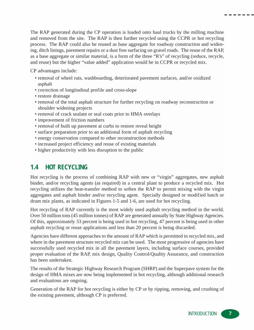
1.4 HOT RECYCLINGHot recycling is the process of combining RAP with new or “virgin” aggregates, new asphaltbinder, and/or recycling agents (as required) in a central plant to produce a recycled mix. Hotrecycling utilizes the heat-transfer method to soften the RAP to permit mixing with the virginaggregates and asphalt binder and/or recycling agent. Specially designed or modified batch ordrum mix plants, as indicated in Figures 1-5 and 1-6, are used for hot recycling.
Hot recycling of RAP currently is the most widely used asphalt recycling method in the world.Over 50 million tons (45 million tonnes) of RAP are generated annually by State Highway Agencies.Of this, approximately 33 percent is being used in hot recycling, 47 percent is being used in otherasphalt recycling or reuse applications and less than 20 percent is being discarded.
Agencies have different approaches to the amount of RAP which is permitted in recycled mix, andwhere in the pavement structure recycled mix can be used. The most progressive of agencies havesuccessfully used recycled mix in all the pavement layers, including surface courses, providedproper evaluation of the RAP, mix design, Quality Control/Quality Assurance, and constructionhas been undertaken.
The results of the Strategic Highway Research Program (SHRP) and the Superpave system for thedesign of HMA mixes are now being implemented in hot recycling, although additional researchand evaluations are ongoing.
Generation of the RAP for hot recycling is either by CP or by ripping, removing, and crushing ofthe existing pavement, although CP is preferred.
7INTRODUCTION

8 INTRODUCTION
Figure 1-6: Drum mix plant with RAP infeed for hot recycling
Figure 1-5: Asphalt batch plant with RAP infeed for hot recycling

As the heat-transfer method is used to soften the RAP for mixing during hot recycling, it is essential that moisture in the RAP be kept to a practical minimum. Excess moisture in the RAP,which tends to retain moisture longer than virgin aggregates, decreases plant production rates asheat is used to turn the moisture to steam instead of heating and softening the RAP.
The amount of RAP used in hot recycling has some practical limitations which are related to planttechnology, gradation of the aggregates within the RAP, physical properties of the asphalt binderin the RAP, and gaseous emission regulations. The ratio of RAP to virgin aggregates used in hotrecycling, has been as high as 85 to 90 percent. However, it is more typically around 15 to 25 per-cent for batch plants and 30 to 50 percent for drum mix plants.
Once the recycled mix has been produced, it is transported, placed, and compacted with conven-tional HMA equipment. No special techniques are required for laydown and compaction, butrecycled mix is frequently placed at slightly lower temperatures than new HMA. The lower tem-perature is a result of efforts to reduce the effects of extremely high temperatures at the asphaltplant. Since the mix temperature is somewhat lower, the recycled mix is “stiffer” which slightlyreduces the amount of time available for compaction.
Hot recycling advantages include:
• conservation of non-renewable resources
• energy conservation compared to other reconstruction methods
• disposal problems inherent in conventional methods are eliminated
• problems with existing aggregate gradation and/or asphalt binder can be corrected withproper selection of virgin aggregates, asphalt binders and/or recycling agents
• curb reveal height and overhead clearance can be maintained
• provides the same, if not better, performance as pavements constructed with 100 percentnew materials
• economic savings are realized
Due to the fact that hot recycling is such a common recycling method with extensive information available, it will not be covered further within this manual.
1.5 HOT IN-PLACE RECYCLING (HIR)With HIR, 100 percent recycling of the existing asphalt pavement is completed on site. Typical treat-ment depths range from 3/4 to 2 inches (20 to 50 mm) although some equipment can treat up to 3inches (75 mm). The process consists of heating and softening the existing asphalt pavement, per-mitting it to be scarified or hot rotary milled to the specified depth. The scarified or loosenedasphalt pavement is then thoroughly mixed and subsequently placed and compacted with conven-tional HMA paving equipment. Virgin aggregates, new asphalt binder, recycling agents and/or newHMA can be added on an as-required basis. Generally, virgin aggregates or HMA addition rates arelimited by equipment constraints to less than 30 percent, by mass of HIR mix. The addition rates ofthe various additives are determined from an analysis of the existing asphalt pavement propertiesand subsequent laboratory mix designs, to confirm compliance with the required mix specifications.
9INTRODUCTION

There are three sub-categories within HIR which are used to further define asphalt recycling,based on the process used. These processes include Surface Recycling, Remixing, and Repaving.The HIR process uses a number of pieces of equipment, including pre-heaters, heaters,heater/scarifiers, mixers, pavers, and rollers. Consequently, the combined equipment spreads outover a considerable distance and is often referred to as a “train.”
Surface Recycling is the HIR process in which softening of the asphalt pavement surface isachieved with heat from a series of pre-heating and heating units. The heated and softened surface layer is then scarified with either a series of spring activated teeth or “tines,” or a smalldiameter rotary milling head to the desired treatment depth. Once the surface has been scarified,the addition of a recycling agent (if required) takes place, the loose recycled mix is thoroughlymixed and then placed with a standard paver screed.
Specified treatment depths generally range from 3/4 to 1 1/2 inches (20 to 40 mm). No new HMAor virgin aggregates are added during the Surface Recycling process so the overall pavementthickness remains essentially the same. Surface Recycling is often used in preparation for a subsequent HMA overlay.
Surface Recycling is the oldest HIR process and is indicated in Figures 1-7 to 1-9.
Compaction of the recycled mix is with conventional rubber-tired, static steel, and/or vibratingsteel drum rollers.
A chip seal or HMA overlay is generally placed in a subsequent operation, although the recycledmix has been left as the surface course on some low volume roads.
10 INTRODUCTION
Figure 1-7: Surface Recycling heating units

11INTRODUCTION
Figure 1-8: Surface Recycling scarification teeth
Figure 1-9: Recycled mix placement

Remixing is the HIR process in which the existing asphalt pavement is heated, softened, and scarified—andvirgin aggregate, new asphalt binder, recycling agent, and/or new HMA is added (as required) and the result-ant, thoroughly mixed. Homogeneous recycled mix is placed in one layer, as indicated in Figure 1-10.
Remixing is generally used when the properties of the existing pavement require significant modification through the addition of any or all of the following: virgin aggregates, new asphaltbinder, recycling agent, and/or new HMA. The recycled mix is usually left as the wearing surfacebut it could be chip sealed or overlaid with new HMA, as a separate operation.
Remixing is also further classified into single and multiple stage methods. In the single stagemethod, the existing asphalt pavement is sequentially heated and softened, and the full depth ofthe pavement to be treated is scarified at one time, as indicated in Figure 1-11. Treatment depthsfor single stage Remixing are generally between 1 to 2 inches (25 and 50 mm).
In the multiple stage Remixing method, the existing asphalt pavement is heated, softened, and scarified in a number of thin layers until the full treatment depth is reached. Usually between twoand four layers are heated and scarified, with the scarified material being placed in a windrow topermit heating and scarification of the underlying layer, as indicated in Figure 1-12. The specifiedtreatment depth for multiple stage Remixing is generally between 1 1/2 to 3 inches (40 to 75 mm).
Both the single and multiple stage Remixing method can add virgin aggregate or new HMA to improvethe characteristics of the existing pavement materials or to increase the overall pavement thickness.The multiple stage method will permit slightly more new materials to be added than the single stagemethod but both are restricted to about 30 percent new materials. Hence, the Remixing process willonly marginally increase the overall pavement thickness unless a subsequent HMA overlay is placed.
12 INTRODUCTION
Figure 1-10: HIR Remixing train

Figure 1-11: Single stage Remixing train
13INTRODUCTION
Figure 1-12: Multiple stage Remixing with windrow of scarified material

Repaving combines the Surface Recycling or Remix process with the placement of a simultaneous or“integral” overlay of new HMA. The Surface Recycled or Remixed layer and the HMA overlay arecompacted together. The thickness of the HMA overlay can be less than a conventional thin lift over-lay since there is a thermal bond between the two layers and they are compacted simultaneously.
In the Repaving process, the surface recycled mix functions as a leveling course while the newHMA acts as the surface or wearing course. The thickness of the new HMA wearing course is afunction of the maximum aggregate size of the mix, but can be as thin as 3/4 inch (20 mm) or asthick as 3 inches (75 mm). Hence, the overall pavement thickness can be increased a significantamount in the Repaving process.
Repaving can also be further classified into multiple and single-pass methods. In the multiple passmethod, the surface recycled mix is placed to the proper longitudinal profile and cross-slope by itsown placing and screeding unit. The new HMA overlay material is then immediately placed on thehot, uncompacted recycled mix with a conventional asphalt paver, as indicated in Figure 1-13.
The two layers are then compacted simultaneously with a series of rubber-tired and double steeldrum vibratory rollers.
With single pass Repaving, one unit equipped with two screeds is used. This unit also scarifiesthe heated, softened pavement, adds the required amount of recycling agent, mixes the recycledmix prior to the first screed, receives the new HMA, and transports it over the recycled mix. Thefirst screed places the recycled mix while the second screed places the new HMA overlay on topof the recycled mix, as indicated in Figure 1-14. The two layers are then compacted with a seriesof rubber-tired and vibrating steel drum rollers.
14 INTRODUCTION
Figure 1-13: Multiple pass repaving

Figure 1-14: Single pass repaving
HIR advantages include:
• conservation of non-renewable resources• energy conservation compared to other reconstruction methods• reduced truck hauling compared with other rehabilitation methods• eliminates the disposal problems inherent in conventional methods• treatment of complete roadway width or only the driving lanes• surface irregularities and cracks are interrupted and filled• improves ride quality• rutting, potholes, and raveling are eliminated• curb reveal height and overhead clearance can be maintained• oxidized asphalt binder can be rejuvenated with the use of recycling agents to restore
pavement flexibility• problems with existing aggregate gradation and/or asphalt binder can be corrected with
proper selection of virgin aggregates, new asphalt binders and/or recycling agents• aggregates stripped of asphalt binder can be remixed and recoated• friction numbers can be restored• hot or thermal bond between longitudinal joints• in-place construction reduces traffic disruptions and user inconvenience• roadway opened to traffic at end of day with little or no edge drop off• economic savings are realized
15INTRODUCTION

1.6 FULL DEPTH RECLAMATION (FDR)FDR is the rehabilitation technique in which the full thickness of the asphalt pavement and a prede-termined portion of the underlying materials (base, subbase and/or subgrade) is uniformly pulverizedand blended to provide an upgraded, homogenous base material. FDR is performed on the roadwaywithout the addition of heat, similar to CIR. Treatment depths vary depending on the thickness of theexisting pavement structure, but generally range between 4 to 12 inches (100 and 300 mm).
FDR consists of pulverization/reclamation of the existing materials, adding more materials (when necessary), mixing, initial shaping of the resultant mix, compaction, final shaping or “tightblading,” and application of a bituminous surface or wearing course.
Reclamation of the existing asphalt bound layers with the underlying materials produces a “granular” pavement layer which can be used as is, can have additional granular materials placedover it, or can be enhanced with the addition of an additive or “stabilizing additive.” The additionof a stabilizing additive is usually required if the reclaimed material does not, by itself, have thenecessary mechanical properties and/or structural strength to support the anticipated loads.
A broad range of stabilizing additives, in either a dry or liquid form, can be used including calciumchloride, magnesium chloride, lime (hydrated or quicklime), fly ash (type C or F), cement kiln dust(CKD) or lime kiln dust (LKD) Portland cement (dry or slurry), asphalt emulsion (normal, high-float,polymer), foamed/expanded asphalt or combinations of two or more of these additives. If the exist-ing materials will not provide the desired gradation, material properties or depth required, additionalgranular or other materials can be added to the roadway prior to or during the FDR process.
Over the years, a number of reclamation methods have been tried, including the use of rippers,scarifiers, pulvi-mixers, milling machines, and stabilizing additives to reclaim the existing surfaceand underlying materials. However, the development of large, high horse-powered, self-propelledreclaiming machines, as indicated in Figure 1-15, has increased the use of FDR due to theincreased treatment depths, higher productivity, and more sophisticated metering systems for thecontrolled addition of the stabilizing additives.
These reclaimers have a specially designed pulverizing/mixing drum equipped with special replace-able tungsten carbide tipped cutting tools. The drum normally rotates in an “up cut” or opposite direction to the forward movement of the reclaimer during the initial pulverization pass. The size ofthe reclaimed material is controlled by the forward speed of the reclaimer, the rotation speed of thepulverization/mixing drum, the position of breaker bar and/or mixing chamber, and the exit dooropening on the mixing chamber. In some processes, the stabilizing additive is added by the reclaimerduring the pulverization pass. This technique has the advantage of eliminating the mixing pass by thereclaimer, and works well for the thinner treatment depths. Addition of the stabilizing additive afterthe pavement has been pulverized, has the advantage of increased and more consistent working speed,and results in a more consistent, uniform application of the stabilizing additive.
FDR equipment consists of a reclaimer unit, stabilizing additive unit or units, motor grader, and rollers.Although not as long as either a HIR or a CIR operation, it is still commonly referred to as a “train.”
FDR recycling trains are configured differently, depending on the recycling application and thetype of stabilizing additive or agents being used. In all cases, the reclaimer either pushes or pullsthe stabilizing additive equipment coupled to it, as indicated in Figure 1-16.
16 INTRODUCTION

Figure 1-15: FDR reclaimer
17INTRODUCTION
Figure 1-16: FDR reclaimer and stabilizing additive tanker

The initial shaping of the roadway after the stabilizing additive (if used) has been added andmixed by the reclaimer, is performed with a motor grader. This is followed with initial com-paction by large sized pneumatic-tired or vibrating steel drum rollers, as indicated in Figure 1-17.
Final compaction and shaping to the required longitudinal profile and cross-slope is followed by a curingperiod, if a stabilizing additive has been used. The curing period is dependent on the type or combinationof stabilizing additives used and the ambient conditions and can range from 1 to 14 days. It is preferablethat heavy truck traffic be kept off the stabilized material during the curing period. The application of asurface treatment or HMA overlay is undertaken as a separate operation at the end of the curing period.
FDR advantages include:
• conservation of non-renewable resources
• energy conservation compared to other reconstruction methods
• few pieces of equipment are required
• elimination of bumps and dips, rutting, potholes, patches, and cracks
• subgrade deficiencies can be corrected by stabilization
• problems with existing aggregate gradation can be corrected with proper selection of newgranular materials
• deteriorated base can be reshaped to restore surface profile and drainage
• significant structural improvement with the addition of stabilizing additive(s)
• produces thick, bound layers that are homogeneous
18 INTRODUCTION
Figure 1-17: Initial shaping with motor grader and compaction

• permits more flexibility in the choice(s) of wearing surface type and thickness
• in-place construction and high production rates improve safety by reducing traffic disruptions and user inconvenience
• economic savings are realized
1.7 COLD RECYCLING (CR)CR consists of recycling asphalt pavement without the application of heat during the recyclingprocess to produce a rehabilitated pavement. Two sub-categories within CR are used to furtherdefine CR based on the process used. These processes are Cold In-place Recycling (CIR) andCold Central Plant Recycling (CCPR). The CIR process uses a number of pieces of equipmentincluding tanker trucks, milling machines, crushing and screening units, mixers, pavers, androllers. Like HIR, the combined equipment spreads out over a considerable distance and there-fore, is commonly referred to as a “train.”
CIR is undertaken on site and generally uses 100 percent of the RAP generated during theprocess. The CIR treatment depth is typically within the 2 to 4 inches (50 to 100 mm) range whenthe recycling agent is only an asphalt emulsion or an emulsified recycling agent. Treatmentdepths of 5 to 6 inches (125 to 150 mm) are possible when chemical additives, such as Portlandcement, lime, kiln dust or fly ash are used to improve the early strength gain and resistance tomoisture damage. If lime or Portland cement is added to the recycled mix, they can be added indry form or as slurry. The slurry method eliminates potential dust problems and permits greatercontrol of the amount of recycling modifier being added.
There are different types of CIR trains with different equipment configurations. The trains differfrom one another in how the RAP is removed and sized, how the recycling additives and modifiers are added, how they are mixed and controlled, and how the resultant mix is placed.
In a single unit CIR train, removal of the RAP is usually performed by a milling machine using adown cutting rotor. The maximum size of the RAP can be kept less than 2 inches (50 mm) bycontrolling the forward speed. Addition and mixing of the recycling additive is performed in themilling machine’s cutting chamber. The placement of the recycled mix is performed with a screedattached to the back of the unit, as indicated in Figure 1-18.
In a single unit train, a predetermined amount of recycling additive is added based on the treat-ment volume which is determined by the treatment width, depth, and the anticipated forwardspeed of the unit. This approach provides the lowest degree of process control, since the treatment volume and the recycling additive application rate are not directly linked.
Two-unit CIR trains usually consist of a large full lane milling machine, and a mix paver. The millingmachine removes and sizes the RAP and deposits it into the mix paver. The mix paver has an infeedbelt with belt scale and a processing computer to accurately control the amount of recycling additiveand modifier being added. Some mix pavers are equipped with scalping screens to remove oversizedmaterial. The mix paver contains a pugmill that mixes the materials and has an automatically controlled screed for mix placement and initial compaction, as indicated in Figure 1-19.
19INTRODUCTION

20 INTRODUCTION
Figure 1-18: Single unit CIR train
Figure 1-19: Two-unit CIR train

In a two-unit train, the liquid recycling additives are added based on the weight of RAP beingprocessed, independent of the treatment width, depth, and forward speed of the train. The two-unit train provides an intermediate to high degree of process control since the treatment volumeand the recycling additive application rates are directly linked.
The multi-unit CIR trains typically consist of a very large, full lane milling machine, a trailermounted screening and crushing unit, and a trailer mounted pugmill mixer. The milling machineremoves the RAP, and final sizing of the RAP is performed in a separate mobile screening/crush-ing unit. Liquid recycling additives are added and the components mixed in a separate pugmillunit. The resultant mix is deposited in a windrow and placed with conventional HMA paversequipped with a windrow pickup machine. In some CIR trains, the screening/crushing unit andthe additive/pugmill units are combined into one larger unit. Another variant is to have the additives and mixing performed in a mix paver, as indicated in Figure 1-20.
The maximum size of the RAP is controlled by the screen sizes used in the screening/crushingunit. Any oversize RAP is sent to the crusher and returned for re-screening. The amount of liquid recycling additive is controlled with the use of a belt scale and a processing computer onthe pugmill unit. The liquid recycling additives are added based on the weight of RAP beingprocessed, independent of the treatment width, depth and forward speed of the train, and therefore, provides the highest degree of process control.
Densification of CR mixes requires more compactive energy than conventional HMA. This is dueto the high internal friction developed between the mix particles, the higher viscosity of the binder
21INTRODUCTION
Figure 1-20: Multi-unit CIR train

due to aging, and colder compaction temperatures. Compaction is usually achieved with a largesized pneumatic-tired roller and vibrating steel drum rollers, as indicated in Figure 1-21.
CIR mixes are compacted as the mixture begins to “break,” turning from brown to black. Whenasphalt emulsions or emulsified recycling additives are used, this could take from 30 minutes to2 hours, depending on the characteristics of the asphalt emulsion, thickness of the CR mix, andenvironmental conditions. The compacted CIR mixture must be adequately cured before a wear-ing surface is placed. The rate of curing is quite variable and depends on several factors, includ-ing environmental conditions and drainage, and moisture characteristics of the mix. Typical cur-ing periods are several days to 2 weeks, depending on the above mentioned factors, and the recy-cling additive and any modifiers used.
CCPR is the process in which the asphalt recycling takes place in a central location using a stationarycold mix plant. The stationary plant could be a specifically designed plant or a CIR train, minus themilling machine, set up in a stationary configuration. The CCPR mix can be used immediately or itcan be stockpiled for later use in such applications as maintenance blade patching or pothole repair.
The RAP used in the CCPR is obtained by CP or by ripping, removing, and crushing operations,and is stockpiled at the plant location. Asphalt emulsions or emulsified recycling agents are typically used as the recycling additive. The asphalt emulsion or emulsified recycling agent type,grade, and addition rate are determined through evaluation of the RAP and the mix design process.New aggregates, if required, are also stockpiled at the plant site. The CCPR plant usually consists of a number of cold feed bins for the RAP and new aggregate, a belt scale, a computercontrolled liquid recycling additive system, a pugmill, a hopper for temporary storage and
22 INTRODUCTION
Figure 1-21: CIR compaction

23INTRODUCTION
Figure 1-23: CIR train set up as a stationary plant
Figure 1-22: CCPR plant

loading of haul trucks or a conveyor/belt stacker, if the CCPR mix is being stockpiled. Figures1-22 and 1-23 on previous page indicate central plant set-ups.
The CCPR mix is hauled to the job site with conventional haul/dump trucks or belly dump trucksif a windrow pickup machine is being used. Placement of the CCPR mix is with conventionalHMA pavers, as indicated in Figure 1-24, but a motor grader could also be used. Compaction iswith conventional large sized rubber-tired and vibrating steel drum rollers. The compacted CCPRmix is generally overlain with a layer of HMA, although for some very low traffic roadways a single or double seal coat is sometimes used.
CR advantages include:
• conservation of non-renewable resources
• energy conservation compared to other reconstruction methods
• eliminates the disposal problems inherent in conventional methods
• surface irregularities and cracks are interrupted and filled
• rutting, potholes, and raveling are eliminated
• base and subgrade materials are not disturbed
• pavement cross-slope and profile can be improved
24 INTRODUCTION
Figure 1-24: CCPR mix placement

• problems with existing aggregate gradation and/or asphalt binder can be corrected with proper selection of new granular materials and stabilizing additives
• significant structural treatment and improved ride quality
• in-place construction and high production rates improve safety by reducing traffic disruptionsand user inconvenience
• economic savings are realized
25INTRODUCTION


Chapter 2CHAPTER 2: REHABILITATION STRATEGIES
The period of rapid expansion of roadway networks through new construction has peaked, theexisting roadway infrastructure has aged, and a significant number of roadways are nearing theend of their useful service life. Limited funding and demands on existing resources have shift-
ed the emphasis from new construction to preservation and/or extending the service life of the exist-ing roadways. The implementation of more timely or proactive preventative maintenance and reha-bilitation treatments is being used as a means of preserving the existing roadway infrastructure.
Pavement Management Systems (PMS) have been designed and implemented in order to assist an agencyin its planning, programming, construction, preventative maintenance, and rehabilitation functions. PMS are also used to evaluate and quantify the condition of a roadway, as a function of age and/or traffic.
The deterioration of a pavement results from a number of different causes and can occur at dif-ferent rates. Data indicates that the deterioration of a roadway pavement will follow a fairlypredictable pattern, for given traffic and environmental conditions.
The serviceability of a pavement is usually related to the pavement’s ability to accommodate theroadway user at a reasonable level of comfort—which is directly related to the roughness of thepavement surface. The serviceability of the pavement changes with time and is related to the:
• original construction quality
• type and thickness of individual layers
• stiffness of the various layers
• subgrade soil type and moisture content
• environmental factors
• types and effectiveness of maintenance activities
• traffic composition and loading
The change in serviceability with time is called “Pavement Performance or PavementServiceability” and is usually expressed as a function of pavement age or cumulative trafficloading. The quantification of pavement serviceability is usually expressed in terms of a subjective, user-related value such as the Riding Comfort Index (RCI), Present ServiceabilityIndex (PSI) or some similar value.
Soon after initial construction, roadways begin to deteriorate, as indicated by a reduction inRCI or PSI values, due to traffic and environmental factors. The shape of the pavement deterioration curve is dependent on a number of factors, including:
• pavement type
• pavement thickness
• initial construction quality
• pavement material properties
• traffic levels
• environmental conditions
• level of maintenance activities, etc.
27REHABILITATION STRATEGIES

The rate of pavement deterioration accelerates with increasing age and traffic. As the deteriora-tion continues, the cost of the rehabilitation increases dramatically, as was indicated in Chapter 1.If no preventative maintenance or rehabilitation is undertaken at the appropriate times, the road-way will quickly deteriorate to the point where expensive reconstruction will be the only option.
Fortunately, with the timely application of preventive maintenance and rehabilitation activitiessignificant extensions to the roadway’s service life can be achieved, as indicated in Figure 2-1.
A wide variety of preventive maintenance and rehabilitation procedures exist which can be usedindividually or in combination to form a strategy to extend the service life of the pavement, in themost cost effective manner.
2.1 PAVEMENT MAINTENANCEPavement maintenance can be categorized as “corrective” or “preventive,” depending on theintended purpose. In general, maintenance activities are intended to:
• prevent moisture from infiltrating the pavement structure
• correct or prevent deterioration due to environmental effects
Preventive maintenance consists of any activity that is intended to preserve or extend the servicelife of a pavement until a major rehabilitation or complete reconstruction is required. In order tomaximize the cost-effectiveness of preventive maintenance, the procedures need to be applied priorto the pavement showing significant signs of distress or deterioration. Preventive maintenance isintended to maintain the durability and flexibility of the pavement. It does not increase the
28 REHABILITATION STRATEGIES
Pav
emen
t C
on
dit
ion
/ R
ide
Qu
alit
y
Time / Traffic
PreventativeMaintenance Rehabilitation Reconstruction
Effect of NoRehabilitation
Effect of NoPreventativeMaintenance
InitialCondition
Figure 2-1: Pavement Deterioration vs. Time

structural strength/capacity, so is generally limited to pavements in good structural condition.
Preventive maintenance includes such activities as:
• Hot In-Place Recycling (HIR)
• HIR with a subsequent surface treatment or thin Hot Mix Asphalt (HMA) overlay
• Cold In-Place Recycling (CIR) with a surface treatment or thin HMA overlay
• fog sealing or coating
• slurry sealing
• micro-surfacing
• chip sealing
• cape sealing
• ultra-thin HMA overlays such as Open Graded Friction Course (OGFC) or Stone MatrixAsphalt (SMA)
The effectiveness of these preventive maintenance techniques varies from agency to agency, and is dependent on the type of technique and materials used, and the quality of the workmanship. The service lives can vary from 1 to 2 years for fog seals to 10 years or more for HMA overlays.
Corrective maintenance addresses existing pavement problems, and includes such routine activities as:
• crack sealing
• pothole repairs
• spray patching
29REHABILITATION STRATEGIES
Figure 2-2: Candidate Road for Preventive Maintenance Recycling

• shallow patching to repair locally distressed areas or to rectify surface irregularities such as bumps and dips
• rut filling
• drainage improvements including cleaning culverts and drains, cleaning and/or re-grading existing ditches, etc.
The effectiveness of these corrective maintenance techniques varies from agency to agency, andis dependent on the type of technique and materials used, and the quality of workmanship.Corrective maintenance techniques have expected service lives of about 1 to 5 years.
2.2 PAVEMENT REHABILITATIONAs the pavement condition deteriorates, there comes a point when maintenance activities are nolonger cost-effective and rehabilitation is required. Rehabilitation techniques are more expensivethan maintenance activities, but the rehabilitated pavement condition will generally be equivalentto what was achieved during the initial construction. Pavement rehabilitation can address:
• poor ride quality or roughness
• pavement deformation, cracking, and rutting
• low friction numbers/safety issues
• surface deterioration and defects
• structural deficiencies
• high user costs
• excessive maintenance patching and costs
There are a considerable number of techniques that can be used either individually or in combinationto rehabilitate a pavement. Rehabilitation techniques include:
• HIR
• HIR with a subsequent surface treatment or HMA overlay
• CIR with a surface treatment or HMA overlay
• Full Depth Reclamation (FDR) with a surface treatment or HMA overlay
• Thin HMA overlays
• Thick HMA overlays
• Cold Planing (CP) and HMA overlay
• CP followed by either HIR, CIR, FDR or Cold Central Plant Recycling (CCPR), and then a HMA overlay
The most important part of the rehabilitation process is the proper selection of the rehabilitationtechnique or techniques to be used. It is often difficult to determine which is the “best” or “right”one to use. In choosing the right rehabilitation technique one must:
• assess the type, amount, and depth of distress the pavement has undergone
• collect and review existing historical information on original construction and subsequent maintenance activities
30 REHABILITATION STRATEGIES

• evaluate the thickness and structural strength of the existing pavement
• determine the physical properties of the existing pavement materials
• determine the cause or causes of the distress
• assess geometric requirements
• select a number of potential rehabilitation techniques based on the previously collected information
• undertake an economic analysis including first cost and life-cycle costs of the potential rehabilitation techniques
• select the most cost-effective rehabilitation technique
Rehabilitation techniques that incorporate asphalt recycling have a number of unique advantagesover the traditional HMA overlay rehabilitation methods. These include:
• reuse and conservation of non-renewable natural resources.
• preservation of the environment and reduction in land filling.
• energy conservation
• shorter construction periods
• reduction in user delays during construction
• increased level of traffic safety within the construction work zone
• preservation of existing roadway geometry and clearances
• corrections to pavement profile and cross-slope
• no disturbance of subgrade soils unless specifically planned, such as for FDR
• improved pavement smoothness
• improved pavement physical properties by modification of existing aggregate gradation,and/or asphalt binder properties
• mitigation or elimination of reflective cracking with some methods
• improved roadway performance
• cost savings
Each of the asphalt recycling rehabilitation techniques offer specific advantages over conventionalmethods. The selection of a particular rehabilitation method must be made based on a detailedproject assessment, as indicated in Figure 2-2, since not all asphalt recycling methods are equallysuited to treat the various pavement distresses.
In addition, when selecting the rehabilitation technique, the process of “Staged Rehabilitation”should be considered. Staged rehabilitation is similar to staged construction, in which not all ofthe required rehabilitation is initially undertaken. Staged rehabilitation is the process whereby theroadway is partially rehabilitated, usually with some form of asphalt recycling technique, and thenmonitored for performance and/or structural capacity. The completion of the staged rehabilitationis undertaken in the future with a HMA overlay, once the overlay thickness reaches a practical oreconomic thickness. Roadways which have a rough ride or poor surface condition, but require noor minimal strengthening, are good candidates for staged rehabilitation.
31REHABILITATION STRATEGIES

Staged rehabilitation alternatives for roadways meeting the preceding requirements include:
• CP with or without a surface treatment
• HIR
• CIR with a surface treatment
• FDR with a surface treatment
A HMA overlay would be placed when conditions warrant. Staged rehabilitation has the addedbenefit of spreading major capital expenditures out over longer periods.
32 REHABILITATION STRATEGIES
Assess Rehabilitation Options
Select Potential Rehabilitation Techniques
Select Rehabilitation Technique
Detailed Design and Analysis
Economic Analysis• Initial Capital Costs• Life-Cycle Costs
• Cold Planing• HIR• CIR• FDR
• Hot Recycling• Thin HMA Overlay• Thick HMA Overlay• Combinations
• Geometrics• Traffic Growth• Performance• Environmental
• Budget• Politics
Determine Cause or Causesof Pavement Distress
Visual Assessment ofPavement Distress
Review of HistoricInformation
Quantify ExistingPavement Properties
• Types• Magnitudes• Severity• Frequency
• Design Data• As-Built Data• QC/QA Data• PMS Data• Maintenance Records
• Roughness• Rutting• Skid Resistance• Deflection (Strength)• Material Properties
Figure 2-3: Rehabilitation technique selection process

Similarly, staged rehabilitation could also be considered for roadways which need immediate attention,but where funds are not available or the roadway will need geometric improvements/grade wideningin the near future. Staged rehabilitation could be considered as a “stop-gap” measure in order to delaythe expenditure of major capital amounts until the full rehabilitation can be undertaken.
As with all rehabilitation methods, project selection for staged rehabilitation is critical to the successful application of the technique.
The effectiveness and performance of the various rehabilitation techniques varies from agency toagency and is dependent on:
• local conditions
• climate
• traffic
• type of technique and quality of materials used
• quality of the workmanship
2.3 PAVEMENT RECONSTRUCTIONReconstruction can be considered the most extreme type of rehabilitation technique. It is oftenthe preferred method when roadway widening or extensive re-alignment, due to geometric considerations, is required. Reconstruction is also required when roadway maintenance or
33REHABILITATION STRATEGIES
Figure 2-4: Candidate Road for Rehabilitation Treatment

rehabilitation has not been undertaken or has not been effective, and the existing pavement has deteriorated to the point where trying to use the existing structure would not be cost-effective.
Reconstruction consists of the total removal of the existing pavement structure, reworking orimproving the subgrade soil, re-compacting the subgrade soil, and placement of a pavement structure with new and/or recycled materials. Due to the extensive construction requirements,associated traffic control, and user inconvenience, it is the most expensive rehabilitation method.
The asphalt pavement and granular base materials can be recycled, reclaimed or reused during thereconstruction process. The use of CP, CCPR, Hot Recycling, and/or FDR techniques can help tosignificantly reduce the overall roadway reconstruction costs.
The effectiveness of the reconstruction varies from agency to agency, and is dependent on the typeof structure constructed, climate, traffic, the type and quality of materials used, and the quality ofthe workmanship. Reconstructed roadways have expected service lives consistent with similarlydesigned and constructed new roadways of up to 20 years.
34 REHABILITATION STRATEGIES

Chapter 3CHAPTER 3: PROJECT EVALUATION
In order to ensure a successful project, project evaluation is by far the most important aspect ofasphalt recycling or reclamation. Although asphalt recycling and reclamation are powerful reha-bilitation methods, not all pavements are appropriate candidates. In addition, not all asphalt
recycling and reclamation methods are equally suited to treat the various types of pavement dis-tresses. If poor judgement is used during the project evaluation process and an inappropriate rehabilitation method is selected, sub-standard roadway performance is sure to follow.
The steps in the rehabilitation selection process were broadly outlined in the discussion of rehabil-itation strategies and indicated in Figure 2-2. The project evaluation process, although generally sim-ilar for all asphalt recycling and reclamation methods, does have some specific steps which areunique to each particular method. In general, the rehabilitation selection process includes:
• visual assessment of the pavement surface• historical information review• pavement properties assessment• distress evaluation• preliminary rehabilitation selection• economic analysis• detailed project design
3.1 PAVEMENT ASSESSMENTAn essential part of the project evaluation process is the determination of the condition of the existing pavement, by conducting a pavement condition or pavement assessment survey. A poor or inadequate pavement assessment could result in the selection of an inappropriaterecycling or reclamation method—which might result in less than expected performance.
Surface distress of asphalt pavements is caused by one or more of the following factors:
• environmental or climatic effects• traffic effects• construction deficiencies• material deficiencies
It is often difficult to allocate surface distress to one single factor since they are usually interre-lated. For instance, a pavement would not rut without heavy traffic loading, but it also would notrut if the pavement temperature didn’t get too hot, if the correct aggregate gradation and asphaltbinder type were used or if it had been adequately compacted at the time of construction.Therefore, rutting distress could be related to traffic, climate, material deficiencies, constructiondeficiencies, or a combination of all four.
35PROJECT EVALUATION

The pavement assessment must consist of a detailed visual inspection which rates all of the surfaceirregularities, flaws, and imperfections found in a given area. The visual inspection should assess:
• all distress types encountered• severity of distress types• frequency of distress types
Various procedures for conducting pavement assessments have been developed by many differentagencies. These include the US Army Corps of Engineers, the American Public Works Association,Strategic Highway Research Project – Long Term Pavement Performance (SHRP-LTPP FR-90-001), etc. The various systems generally use a manual that provides detailed descriptions of eachtype of pavement distress, how the distress is to be measured, along with guidelines for the classi-fication of the severity and frequency of the distresses. The manuals usually include photographsthat illustrate the various distress types, along with severity levels, to assist the surveyor in doing aproper and consistent classification.
It is extremely important that whatever procedure is adopted, it be constantly applied throughoutan agency, since the various procedures could produce significantly different results. Consistencyof the visual condition survey data is achieved through providing the survey team proper training,establishing control sections, and the use of blind comparisons among surveyors.
Collection of the pavement surface condition by automated or semi-automated inspection equip-ment is increasing—due to improvements in the assessment technology, increased concern forsurveyor safety, rising costs of manual inspections, and the cost and inconvenience to motorists.
Although the various pavement assessment methods vary from one another, the general principlesremain the same, i.e., visually assess, record, assign severity rating, and determine frequency ofeach distress type. The pavement assessment is generally summarized or quantified into a numer-ical value such as a Pavement Condition Index (PCI), Surface Distress Index (SDI) or similar value.
Surface distress of an asphalt pavement can be grouped into six major categories which include:
• surface defects• deformations• cracking• maintenance activities• base/subgrade problems• ride quality• safety
3.1.1 SURFACE DEFECTSSurface defects are generally related to material and construction deficiencies, with secondarycontributions by traffic, and climatic conditions. Surface defects include:
• Raveling or weathering which is the deterioration of the pavement surface due to the loss ofaggregate particles and asphalt binder. The distress is progressive in nature. The fine aggre-gate particles are lost first, followed by coarser aggregate particles as the condition increasesin severity. Raveling may also be an early indicator that the aggregates are water sensitive andmay be susceptible to stripping.
36 PROJECT EVALUATION

Raveling can also be associated with poor quality Hot Mix Asphalt (HMA) (low asphalt bindercontents, soft aggregates, etc.), construction deficiencies (low compaction, mix segregation,etc.), age-hardening of the asphalt binder (overheating of the HMA mix during production),certain types of traffic conditions (studded tires, tracked vehicles, etc.), and environmentalconditions (freeze-thaw, wet-dry, abrasion effects of winter sanding operations).
In isolated instances, raveling can be caused by the effects of oil or fuel spills which soften thesurface of the pavement, permitting the aggregate particles and asphalt binder to be removed.
• Potholes are bowl-shaped depressions in the pavement surface in which a significant thicknessof the pavement surface has been dislodged. They are generally less than 30 inches (750 mm)in diameter, greater than 3/8 inches (10 mm) in depth, have sharp edges, and vertical sides nearthe top.
Potholes can be associated with poor quality HMA (low asphalt binder contents, soft aggre-gates, etc.), construction deficiencies (low compaction, mix segregation, etc.), structural problems(insufficient pavement thickness, reduced base support, etc.), and environmental conditions(freeze-thaw cycles, etc.).
• Bleeding or flushing are areas of the pavement surface that have a shiny, glass-like reflectingappearance that usually becomes quite sticky in warmer weather due to a film of excessiveasphalt binder. Bleeding areas become very slippery, particularly in wet weather conditions.
Bleeding can be associated with poor quality HMA (excessive asphalt binder contents, too softof an asphalt binder, low air voids, etc.), construction deficiencies (excessive tack or prime coatapplication, etc.), environmental conditions (excessively hot weather, etc.), and traffic effects
37PROJECT EVALUATION
Figure 3-1: Pothole Pavement

(high traffic volumes, etc.). Bleeding occurs when excess asphalt binder fills the voids in themix and then moves upward to the pavement surface in a non-reversible, cumulative process.
Bleeding may also develop with chip seals where the asphalt binder application rate was toohigh, the aggregate application rate too low or excessive aggregate loss has occurred.
• Friction Number is the amount of friction between the pavement surface and vehicle tires.The friction number is reduced when the surface of the pavements are wet/icy; when the portion of the coarse aggregate particles extending above the asphalt binder is very small;when there are no angular particles to provide a rough surface texture; and/or under traffic thecoarse aggregates becomes polished. Pavements which have low numbers usually have a verysmooth surface texture. Loss of friction number is detected by testing and is usually progres-sive, particularly if the coarse aggregate is susceptible to polishing due to traffic.
• Lane/Shoulder Drop-off is a difference in elevation between the pavement edge and the road-way shoulder. This distress can be a result of shoulder erosion, shoulder settlement, or by thebuild up of the roadway through HMA overlays without adjustment of the shoulder level. Itpresents a safety concern which should be addressed during the project evaluation and rehabilitation selection process.
3.1.2 DEFORMATIONSAsphalt pavements may exhibit permanent deformation or distortion which are generally relatedto traffic loading and material deficiencies, with secondary contributions due to constructiondeficiencies and climatic conditions. Deformations in one form or another are usually caused bya combination of traffic effects or HMA which lacks internal stability due to high asphalt bindercontents, has too soft of an asphalt binder, has high fine aggregate contents, contains too muchround natural sand, has excessive smooth or round coarse aggregates, and/or were inadequatelycompacted. Deformations include:
• Rutting which are longitudinal depressions or channels within the wheelpaths of roadways. Threebasic types of rutting can occur in an asphalt pavement consisting of wear rutting, structural rutting,and instability rutting. Rutting is generally more noticeable after rainfalls, when the rut fills withwater. As the rut depth increases, the amount of water trapped in the rut increases, reducing the friction number and increasing the risk of hydroplaning.
Wear rutting is caused by the progressive loss of material from the roadway surface. It is usuallydue to poor quality HMA, inadequate compaction of the HMA at the time of construction, and/orby the use of studded tires. Wear rutting is not accompanied by an upward movement of the pavement surface adjacent to the rut. The surface texture within the rut has a slight raveled appearance, and the rut widths are fairly narrow or confined.
Structural rutting is the cumulative, permanent vertical deformation of the various pavementlayers as the result of repeated heavy traffic loads. Most structural rutting occurs within theunderlying subgrade, particularly when the thickness of the pavement is insufficient to adequately distribute the imposed traffic loads. In structural rutting the width of the ruts areusually fairly wide in cross-section, the rut is bowl shaped with the greatest deformationoccurring at or near the middle of the rut, and no noticeable upward deformation of the pavement adjacent to the rut can be observed.
38 PROJECT EVALUATION

Instability rutting is the result of shear displacement of one or more of the HMA layers frombeneath the wheelpath areas. The HMA is displaced downward, laterally, and then upward toform ridges on either side of the wheelpath. Instability rutting has become more prevalent dueto higher tire pressures, increased wheel loadings, and higher traffic volumes. Instability rutting is usually accompanied by an upward movement of the pavement surface adjacent tothe rut, a rut within a rut or “W” shape, and a narrow to medium rut width.
• Corrugations or washboarding are a series of closely spaced ridges and valleys or “ripples” of the pavement surface primarily in wheelpath areas. The corrugations are at a regular and closely spaced interval, usually less than 10 feet (3 meters) and ripples are perpendicular to the direction of traffic. Corrugations can occur where traffic starts/stops oron steep hills where vehicles brake sharply going downhill.
Corrugations are permanent deformations that are progressive in nature, starting from smallindentations or “dimples” and progressively becoming larger under the influence of traffic.
“Mini-corrugations” of a new HMA can sometimes be observed outside of the wheelpathareas. These mini-corrugations are very closely spaced; usually less than 4 inches (100 mm)apart and the ripples are very shallow. This type of corrugation is caused by improper opera-tion of steel drum vibratory rollers during the HMA compaction operation. The mini-corru-gations can occur when the steel drum vibratory rollers are being operated at a forward speedgreater than what is required for the proper number of vibratory impacts per foot (meter).
• Shoving is also a form of permanent deformation caused by plastic movement of the HMA ina longitudinal direction. Shoving appears as a localized bulging of the pavement surface andis usually associated with some form of discontinuity within the pavement structure, such aswhere the pavement abuts a Portland Cement Concrete (PCC) structure.
3.1.3 CRACKINGThere are three primary types of asphalt pavement cracking: load associated; non-load associat-ed; and combination. Load associated cracking is due to the repeated application of heavy wheelloads. Non-load associated cracking is due to environmental factors, and combination crackingis due to a combination of both load and non-load effects.
Load associated cracking includes:
• Fatigue or “alligator” cracking is a series of interconnected cracks caused by a fatigue failureof the pavement structure due to repeated heavy traffic loading. The fatigue cracks usuallybegin at the bottom of the asphalt layer, where the tensile stresses are the highest under wheelloading. The cracks propagate to the pavement surface initially as a series of parallel, longi-tudinal cracks or wheelpath cracks. Under continued traffic loading, the cracks connect,forming many-sided, sharp-angled pieces that develop a pattern which resembles the skin ofan alligator or the shape of chicken wire. The broken pieces of pavement are generally lessthan 20 inches (500 mm) on the longest side.
In most cases, the fatigue cracking is caused by excessive deflection of the pavement surfaceover an unstable base or subgrade.
• Edge cracks are parallel to and usually within 12 to 24 inches (300 to 600 mm) of the outeredge of the asphalt pavement. Edge cracking is accelerated by traffic loading, particularly for
39PROJECT EVALUATION
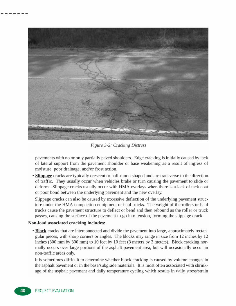
pavements with no or only partially paved shoulders. Edge cracking is initially caused by lackof lateral support from the pavement shoulder or base weakening as a result of ingress ofmoisture, poor drainage, and/or frost action.
• Slippage cracks are typically crescent or half-moon shaped and are transverse to the directionof traffic. They usually occur when vehicles brake or turn causing the pavement to slide ordeform. Slippage cracks usually occur with HMA overlays when there is a lack of tack coator poor bond between the underlying pavement and the new overlay.
Slippage cracks can also be caused by excessive deflection of the underlying pavement struc-ture under the HMA compaction equipment or haul trucks. The weight of the rollers or haultrucks cause the pavement structure to deflect or bend and then rebound as the roller or truckpasses, causing the surface of the pavement to go into tension, forming the slippage crack.
Non-load associated cracking includes:
• Block cracks that are interconnected and divide the pavement into large, approximately rectan-gular pieces, with sharp corners or angles. The blocks may range in size from 12 inches by 12inches (300 mm by 300 mm) to 10 feet by 10 feet (3 meters by 3 meters). Block cracking nor-mally occurs over large portions of the asphalt pavement area, but will occasionally occur innon-traffic areas only.
It is sometimes difficult to determine whether block cracking is caused by volume changes inthe asphalt pavement or in the base/subgrade materials. It is most often associated with shrink-age of the asphalt pavement and daily temperature cycling which results in daily stress/strain
40 PROJECT EVALUATION
Figure 3-2: Cracking Distress

cycling. Block cracking can also indicate that the asphalt binder has hardened significantly.
• Longitudinal cracks are parallel to the centerline of the roadway or HMA laydown direction.They can develop along the construction joint between adjacent passes of the paver or at alocation which corresponds to the center of the paver. Poorly constructed paving joints orworn out paver kicker screws/paddles accelerate the development of longitudinal cracking.
• Transverse or thermal cracks extend across the asphalt pavement approximately at right anglesto the pavement centerline or direction of HMA laydown. Transverse cracks start at the pave-ment surface and propagate downward through the asphalt layers. They initially occur as a sin-gle crack but can develop into multiple or “braided” cracks under the influence of traffic.
Transverse cracks are due to the shrinkage of the asphalt pavement due to low temperatures,hardening of the asphalt binder, and/or large daily temperature cycling. They usually start oneor two seasons after construction (particularly, low temperature transverse cracks) at a widespacing, in the order of 300 to 1000 feet (100 to 300 meters) apart. The crack frequencyincreases or the crack spacing decreases progressively over time. For a given environment, theoccurrence of transverse cracks is directly related to the temperature susceptibility of theasphalt binder used in the original HMA.
• Reflection cracks are cracks in HMA overlays which reflect the crack pattern that existed in theunderlying pavement prior to placement of the overlay. Reflection cracks can be longitudinal,transverse or random depending on the configuration of the underlying cracks. They are due tostress created by the horizontal and vertical movement of the underlying pavement structure.
Combined load and non-load associated cracking includes:
• Joint Reflection cracking that occurs in asphalt pavement placed on PCC slabs and are dueto the thermal or moisture induced movement of the PCC. The initial crack reflection is non-load associated, but traffic loading usually causes a further breakdown of the asphalt pavementsurface adjacent to the crack. These cracks progress from a single crack, to a braided crack, toa “spalled” crack in which pieces of asphalt pavement are dislodged.
• Discontinuity cracks occur when there is a significant difference in total pavement structureor age of the pavement structures. They typically are associated with roadways which havebeen widened. Discontinuity cracks are a result of the differential movement between theexisting and widening pavement structures. They tend to be more severe if the discontinuityhappens to be in or near a wheelpath.
3.1.4 MAINTENANCE ACTIVITIESMaintenance activities include skin patching, failure repairs, pothole filling, utility cutrepair/restoration, crack sealing, spray patching, etc. These types of surfacing activities are usually undertaken to correct a pavement deficiency and are considered a defect no matter howwell it is performing. A patched area or the pavement adjacent to a maintenance activity usuallydoes not perform as well as the intact pavement. There is generally some increased roughnessassociated with the maintenance activity, no matter how well it was placed.
The presence of surface treatments such as fog seals, chip seals, micro-surfacing, etc. should alsobe noted and their condition recorded.
41PROJECT EVALUATION

3.1.5 PROBLEM BASE/SUBGRADESSevere cracking, pavement failures, settlements, depressions, and structural rutting of asphaltpavements are often the result of a poor base or subgrade, particularly with thinner pavementstructures. A wet, soft base or subgrade creates problems due to its lower strength and load-car-rying capabilities. Problem bases and subgrades are susceptible to pumping and displacement ofmaterial through the cracks in the pavement structure. Base and subgrade problems can also man-ifest themselves as swells, bumps, sags or depressions which can initiate surface cracking.
• Swells are characterized by upward displacement of the pavement surface in a long, gradualwave which is more than 10 feet (3 meters) in length. Swells are usually the result of frostheaving or swelling soils.
• Bumps are characterized by small, localized upward displacement of the pavement surface.They can be caused by localized frost heaving and swelling soils, infiltration and build up ofnon-compressible materials in the crack which can lead to “tenting,” and/or buckling orbulging of underlying PCC slabs.
• Sags are small, abrupt downward displacement of the pavement surface, usually initiated withloss or settlement of the underlying base or subgrade. When sags occur in association withcracking, they are sometimes referred to as “dipping” or “cupping.”
• Depressions are localized areas which have a slightly lower elevation than the surround pave-ment surface. They are not normally noticeable except after rainfall when they pond watercreating “birdbaths.” Depressions are usually created by consolidation or settlement of the
42 PROJECT EVALUATION
Figure 3-3: Base and Sub-Base Deficiences

subgrade or underlying soils. They also can be created as a result of improper construction.Depressions increase the roadway roughness and if deep enough can create safety hazardswhen filling with water, causing hydroplaning.
Problem base and subgrades can be affected by the drainage condition adjacent to the roadways.Ditch grades, culvert condition, groundwater/springs, etc. must also be assessed to determinewhether they are having an impact on the performance of the pavement.
The size, location, and frequency of base and subgrade problems give a good indication of theoverall structural integrity of the existing pavement structure.
3.1.6 RIDE QUALITYRide quality must be evaluated in order to establish a severity level for roughness, with the following factors being included:
• bumps and sags• corrugations, shoving and rutting• swells and depressions• cracking (tenting and dipping)• bridges and railway crossings• maintenance activities• cross-slope and general unevenness
To determine the effect of theses factors on ride quality, the roadway should be driven at the postedspeed limit in a vehicle that is representative of those typically using the roadway. Pavement sections near intersections and stop signs should be evaluated at an appropriate deceleration speed.
3.1.7 SAFETY EVALUATIONWhen a pavement is evaluated in terms of safety, several components are assessed, including:
• friction number• overall condition of the pavement surface• light reflectivity• side slopes and adjacent structures• lane markings• roadside hazards
Friction number, rutting, and overall pavement surface condition are the most common indicatorsof a potential safety problem.
3.2 HISTORIC INFORMATION REVIEWHistoric or existing information should also be reviewed as part of the rehabilitation selectionprocess. Information which should be gathered and assessed includes:
• original design information
43PROJECT EVALUATION

• as-built/constructed data• Quality Control/Quality Assurance construction data• Pavement Management System (PMS) data• maintenance activity records
The amount of historic information will vary from project to project and from agency to agency.Obviously, the greater the amount of historic information and the more detailed or project specif-ic it is, the easier it will be to determine the cause or causes of the pavement distresses observedin the pavement assessment. If the cause or causes of the pavement distresses can be determinedto a higher degree of certainty or confidence, then evaluation and selection of an appropriate reha-bilitation technique will be easier.
3.3 PAVEMENT PROPERTIES ASSESSMENTDuring the pavement assessment phase the condition of the roadway surface was subjectivelyrated based on its visual appearance. In order to provide additional data, to assist in the determi-nation of the cause or causes of the pavement distress, quantification of the existing pavementproperties will need to be undertaken. This will include determination of the physical propertiesof the pavement both in the field and in the laboratory by means of testing. Physical propertiesof the pavement which should be measured include:
• roughness• rutting• friction number• strength• material properties
3.3.1 ROUGHNESSRoughness is distortion of the pavement surface which contributes to an uncomfortable or unde-sirable ride quality. The degree to which a rough roadway affects the operation of vehicles usingit depends on a number of factors, including the amplitude and frequency of the pavement dis-tortions, suspension characteristics of the vehicles, and vehicle speed.
The devices and methods used to quantify pavement roughness can be divided into three basic categories:
• subjective ratings• profile measuring devices to obtain pavement profile data• response measuring devices which measure the reaction of a vehicle as it moves over the
pavement
The devices and methods for collecting roughness data range from the traditional rod and levelsurveys, to high speed, non-contact methods. The device or method selected depends on therequired speed of data collection, required accuracy of the data, and size of the sample.
The subjective rating methods are the least accurate but relatively fast. The profile measuringdevices are the most accurate, but relatively slow, and the response measuring devices fall in
44 PROJECT EVALUATION

between. Each method produces it own unique way of expressing roughness such as RidingComfort Index (RCI), Riding Comfort Rating (RCR), or something similar.
The International Roughness Index (IRI) is becoming the standard for pavement roughness meas-urement and analysis, since it is valid for any road surface type, and it covers all levels of rough-ness. Roughness measurements and ratings from the difference measurement devices and meth-ods have sometimes been correlated with each other and to the IRI, for comparison purposes,although the correlations are not universally applicable.
Pavement roughness can be used to monitor pavement serviceability, and is directly related tovehicle operating costs. The initial or as-built smoothness of a pavement directly affects its serv-ice life, as smooth pavements will generally last longer and require less maintenance than roughpavements.
Roughness is most frequently the triggering factor which identifies a roadway as a candidate forrehabilitation or reconstruction.
3.3.2 RUTTINGAs the severity of pavement rutting increases, there is a corresponding decrease in roadway safety,since severe ruts adversely affect the handling characteristics of vehicles using the roadway.The roadway safety is impacted by:
• rut shape and depth• type of vehicle and vehicle speed• types of tires and tire wear• porosity of the pavement surface, cross-slope and longitudinal profile• surface conditions (wet or dry)• rainfall intensity and duration, etc.
Pavement ruts can be assessed from simple visual estimates—to automated techniques which useultrasonic or lasers to measure the transverse profile of a roadway from a vehicle moving at highway speeds. However, most often the depth of the rutting is measured by placing a referencestraightedge, usually 4 to 10 feet (1.2 to 3.0 meters) in length, across the rut, and measuring thedistance from the bottom of the straightedge to the deepest part of the rut. This indicates the maximum rut depth relative to the length of the straightedge. It is noted that other ways of reportingrut depth exist, such as average rut depth (the maximum rut depth divided by rut width), hence,any comparison of rut depth needs to be accompanied by a description of how the rut depth wasmeasured.
Rutting is the second most frequent trigger factor identifying roadways as candidates for rehabilitationor reconstruction.
3.3.3 FRICTION NUMBERFriction number is a very complex phenomenon which depends on the interrelationships betweenpavement, vehicle, environmental, and driving factors. It is largely dependent on the “micro-texture”of the coarse aggregates at the pavement surface. Micro-texture is a function of aggregate mineralogy
45PROJECT EVALUATION

and its interaction with traffic and climatic effects. Friction number can change rapidly in the shortterm, usually related to surface conditions such as rainfall. Over the longer term, with the applica-tion of traffic, most pavements show a progressive decrease in friction number. Changes in the pave-ment surface which are possible contributors to reduction in friction number over time and traffic are:
• surface wear
• rutting• bleeding or flushing of asphalt binder• contamination• porosity of the surface• polishing of surface aggregates
Many different methods and devices are currently used to collect friction number data in a variety of modes. Standards have been established, such as American Society for Testing andMaterials (ASTM) E274 “Test Method for Skid Resistance of Paved Surfaces Using a Full ScaleTire,” since ascribing a friction number value to a pavement without specifying tire, speed, temperature, water film thickness, etc., is not technically correct. Friction number as measuredby ASTM E274 is termed “Skid Number.”
3.3.4 STRENGTHThe evaluation of pavement strength, structural adequacy, structural strength, load-carrying capacityor structural capacity can be estimated by an evaluation of the pavement materials, subgrade, andthicknesses, or by direct field measurements. The ability of an existing pavement to carry the anticipated future traffic at a reasonable level of service is directly related to its structural capacity.
Evaluation of the structural capacity of an existing pavement can be determined by either destructive or non-destructive methods.
Destructive or intrusive methods include probe holes, test pits or coring too:
• determine the existing pavement layer thicknesses• assess the existing strength by means of Dynamic Cone Penetrometer (DCP) tests,
Field Vane tests, field California Bearing Ratio (CBR) tests, etc.• sample the existing pavement materials for subsequent material characterization in
the laboratory
Knowing the thickness of the various pavement layers and the results of the laboratory testing, theexisting roadway structure can be mathematically converted, by means of material equivalencies,into a single value such as the Granular Base Equivalency (GBE), Structural Number (SN) orsomething similar. This computed value can then be compared to the minimum acceptable valuerequired to accommodate the anticipated future traffic.
The material equivalency values range widely from material to material and are area/region or agencyspecific. Use of material equivalencies from different regions or agencies must be verified for theirapplicability on a project specific basis. Due to the somewhat subjective method in determining thematerial equivalencies, the evaluation of the roadway’s existing structural capacity, by this method, isalso somewhat subjective.
46 PROJECT EVALUATION

Non-destructive methods evaluate the existing structural capacity, usually by determining thepavement response or deflection to an imposed load. Non-destructive deflection testing devicescan be divided into three broad categories which include:
• static deflection or slow-moving devices• vibratory devices• dynamic impact devices
Static or slow-moving devices include the Benkelman beam, plate load tests, curvature meters, etc.These devices are simple to use and inexpensive to purchase, but they take longer to obtain data,present a safety concern for operators during data collection, and are labor intensive. In addition,the tests do not accurately simulate the effects of moving wheel loads and their repeatability is low.
Vibratory devices include Dynaflect, Road Rater, WES heavy vibrator, etc. These devices have theability to measure the deflection basin, as opposed to a single point, are generally easy to operate,acquire data quickly, and have good repeatability, but they are expensive. In addition, the test loadsapplied to the pavement are generally much lower than actual wheel loads, therefore extrapolationof the data is necessary.
Dynamic impact devices include Falling Weight Deflectometers (FWD), etc. They tend to simulate moving wheel loads with a higher degree of accuracy, repeatability is very good, dataacquisition is quick and automated, but they are very expensive. In addition, deflectionbasin/bowl information can be used in more advanced mechanistic-empirical design methods byback-calculation of the subgrade resilient modulus and the effective pavement modulus.Deflection bowl measurements can also be used to calculate various pavement parameters that canbe compared to performance criteria, including:
• surface curvature index• base damage index• base curvature index
The surface curvature index indicates the relative stiffness of the upper portions of the pavementwhich are usually asphalt bound layers. The base damage index and base curvature index indicatethe relative stiffness of the materials lower in the pavement section. High values for the surface cur-vature index would indicate a weakness of the upper pavement layers, while high values for the basedamage index and base curvature index would indicate weakness in the lower pavement structures.
3.3.5 MATERIAL PROPERTIESUtilizing the information gathered during the visual assessment of the pavement surface, the reviewof historic documents, and the pavement property assessment, the project is divided into sectionswhich have the same performance characteristics or which are homogeneous/uniform. For eachsection of the project, two different means of choosing sample locations could be used. The firstis a fixed interval sampling plan and the second is a random sampling plan. Whichever samplingmethod is used, it should be unbiased and avoid sampling the worst areas exclusively, since this willresult in a misleading view of the project. In addition, sample locations should vary across theroadway width so as not to be in a constant position such as the outer wheelpath. Obviously, thelocation of the samples needs to be recorded and assessed during the evaluation stage, since different results are expected for samples obtained in wheelpath areas, as opposed to non-
47PROJECT EVALUATION

wheelpath areas. If additional sampling is undertaken to assess specific areas, distresses or failures, these should be kept separated from the overall project assessment samples and evaluation.
Field samples are then obtained to determine the:
• in-situ asphalt pavement density, asphalt binder content, extracted aggregate gradation,aggregate angularity, flat and elongated particles, and perhaps petrographic analysis
• in-situ asphalt pavement air voids (Va), voids in mineral aggregates (VMA), voids filledwith asphalt (VFA), and perhaps resilient modulus
• penetration, absolute and/or kinematic viscosity of the recovered asphalt binder, and perhaps it’s temperature susceptibility or Superpave PG characterization
• gradation, moisture content, angularity, Plasticity Index, and perhaps resilient modulus of the base and sub-base aggregates
• subgrade soil type, Plasticity Index, moisture content, and strength• groundwater conditions
Samples should be of sufficient size so that they will provide a reasonable representation of thematerial. All samples should be visually inspected as part of the assessment process to see whetherthey match what was indicated in the historical records. This is particularly important for theasphalt pavement layers, since interlayers such as seal coats/chip seals, rubber modifiers, delami-nations, paving fabrics/geotextiles, etc. can have a significant impact on the choice of rehabilita-tion techniques. The pavement samples should be evaluated for evidence of stripping of the asphaltbinder, such as bare or uncoated aggregate, friable or disintegrating mix, and excessive moistureretention. Water retention in older pavements can affect the rehabilitation alternative and is oftenoverlooked, since core samples are usually obtained with water as the cooling fluid.
3.4 DISTRESS EVALUATIONThe results of the visual assessment, historical information review, and pavement property assessmentare used to evaluate and determine the cause or causes of the pavement distress. If a definite causefor the pavement distress cannot be found, additional investigative work may be required in order tofully understand the behavior of the pavement.
One method that can be used to help determine where the weakness in a pavement structure islocated is to correlate the surface deflection with rut depth. If there is a positive correlationbetween deflection and rut depth, i.e., an increase in rut depth with an increase in deflection, a weaksubgrade/base structure is indicated. If there is no correlation between rut depth and deflection,weakness in the upper pavement layers is most likely indicated.
Width of the surface rutting is also a useful indicator of where the pavement weakness may be found. Wideruts can indicate deeper seated weaknesses, while relatively narrow ruts can indicate upper layer weakness.
The various pavement distresses and potential contributing factors to the pavement distresses are as follows:
48 PROJECT EVALUATION

3.5 PRELIMINARY REHABILITATION SELECTIONOnce the cause or causes of the pavement distress have been determined, assessment and selec-tion of candidate or preliminary rehabilitation techniques/methods to address the pavement dis-tress can begin. It has been assumed that the pavement surface condition has deteriorated to thepoint where preventive and corrective maintenance techniques are no longer viable alternativesand that some form of rehabilitation is required.
The first step in the assessment of preliminary rehabilitation techniques is to determine:
• What and how severe are the distresses which require the pavement to be rehabilitated?• Are the existing materials of sufficient quality to be recycled? If not can they be improved
during the rehabilitation process?• What design life is expected of the rehabilitated pavement?• What is the anticipated traffic growth and Equivalent Single Axle Loads (ESAL’s) for the
expected design life?• What is the structural capacity of the existing pavement?• Does the existing pavement have sufficient structural capacity to handle the expected design
life and/or traffic without strengthening?
49PROJECT EVALUATION
RavelingPotholesBleedingSkid ResistanceShoulder Drop OffRuttingCorrugationsShovingFatigue CrackingEdge CrackingSlippage CrackingBlock CrackingLongitudinal CrackingTransverse CrackingReflection CrackingDiscontinuity CrackingSwellsBumpsSagsDepressionsRide QualityStrength
Pavement DistressMode
Base/Subgrade Traffic Environment ConstructionHMA
PropertiesPavementStructure
More Likely Less Likely
Potential Contributing Factors to Pavement Distress
Comparison of the results of the investigations and the original design assumptions or methodscan also be useful in determining the cause or causes of pavement distress.
• Is the existing structure strong enough to support the rehabilitation equipment?• If strengthening is required what thickness of HMA overlay is needed?• Is the surface and sub-surface drainage adequate?• What performance standard, such as riding quality, etc., is required of the rehabilitated pavement?• What level of maintenance is envisioned during the expected design life of the rehabilitated
pavement?• Are any geometric corrections, such as alignment, width, etc., required during the design period?• Are there any safety issues which need to be addressed during the rehabilitation?• What are the types and location of surface and underground services/utilities which will be
affected by the rehabilitation?• Are there any environmental issues, such as temperature, rainfall, etc. which need to be
addressed?• What are the construction limitations, such as traffic accommodation, hours of work, long
grades, roadway widths, shaded areas, overhead clearances, drainage structures, curb andgutter, guardrails, etc. which will have an impact on the rehabilitation technique?
• What will be the impact on adjacent businesses/public?• What size is the rehabilitation project?• What is the availability of experienced contractors and equipment?• What is the available budget?
The answers to these questions will significantly influence the type of rehabilitation or recon-struction technique that should be considered.
There are a considerable number of rehabilitation techniques which can be used either individu-ally or in combination to rehabilitate a pavement. Rehabilitation techniques include:
• Hot In-Place Recycling (HIR) - Surface Recycling• HIR Surface Recycling with a subsequent surface treatment or a HMA overlay• HIR Remixing• HIR Remixing with a subsequent HMA overlay• HIR Repaving• Cold In-Place Recycling (CIR) with a surface treatment or HMA overlay• Cold Planing (CP) with or without a HMA overlay• Thin HMA overlay• Thick HMA overlay• CP followed by either HIR, CIR, FDR or Cold Central Plant Recycling (CCPR),
and then a HMA overlay• Full Depth Reclamation (FDR) with a surface treatment or HMA overlay• Reconstruction with CP, FDR and/or CCPR, and then HMA
The selection of candidate or feasible rehabilitation techniques can be made based on:
• judgement and experience• a decision tree or logic diagram which models local practice• an artificial intelligence approach such as expert systems
50 PROJECT EVALUATION

The following table provides a general guideline for the preliminary selection of candidate recycling or reclamation methods for the rehabilitation of asphalt pavements.
All of the candidate rehabilitation techniques have advantages and disadvantages relative to one another,since not all rehabilitation techniques are equally suited to treat the various pavement distresses. The ability of a rehabilitation technique to correct a pavement distress is dependent on the type of pavementdistress, as well as the extent of the distress and its severity. In addition, local aggregate quality, amount/type of traffic, and climatic conditions are also important factors which need to be considered.
The choice of preliminary rehabilitation techniques should be made based on engineering considerations and the subsequent economic analysis.
3.6 ECONOMIC ANALYSISAn economic analysis is undertaken to compare the different rehabilitation techniques, in order to determine the one which will maximize the monetary effectiveness. This is usually done bycomparing the life-cycle costs of the various rehabilitation alternatives being considered.
A life-cycle cost refers to all costs/expenses and benefits related to the roadway which occur over afixed analysis period. Some of the cost components to be accounted for in the analysis period include:
• initial rehabilitation costs
51PROJECT EVALUATION
RavelingPotholesBleedingSkid ResistanceShoulder Drop OffRuttingCorrugationsShovingFatigue CrackingEdge CrackingSlippage CrackingBlock CrackingLongitudinal CrackingTransverse CrackingReflection CrackingDiscontinuity CrackingSwellsBumpsSagsDepressionsRide QualityStrength
Pavement DistressMode
LeastAppropriate
MostAppropriate
CP HIR CIR ThinHMA
ThickHMA
FDR CombinationTreatments
Reconstruction
Candidate Rehabilitation Techniques

• future rehabilitation costs• maintenance costs• residual or salvage value• engineering and administrative costs• user costs (travel time, vehicle operation, accidents, discomfort, delay costs and extra
operating costs) during rehabilitation and maintenance activities
Other costs might include aesthetics, pollution, noise, etc., but these are difficult to quantify andare usually dealt with in a subjective manner.
Several different economic models can be used, including:
• present worth• equivalent uniform annual cost• rate-of-return• benefit-cost ratio• cost-effectiveness
The Present Worth Method is the most widely used in the transportation field. It consists of com-bining all costs and benefits, in terms of discounted dollars which occur at different times over theanalysis period, and translates them into a single amount at a particular point in time, usually the present.
The Equivalent Uniform Annual Cost Method combines all initial capital costs and all recur-ring future expenses into equal annual payments over the analysis period.
The Rate-of-Return Method considers both the costs and benefits. It involves a determinationof the rate at which costs/benefits for a project are equal. It can also be in terms of the rate atwhich the equivalent uniform annual cost is exactly equal to the equivalent uniform annual benefit.
The Benefit-Cost Ratio Method involves expressing the ratio of the present worth of benefits ofany alternative to the present worth of costs or the ratio of the equivalent uniform annual benefits tothe equivalent uniform annual costs. The benefits are established by a comparison of alternatives.
The Cost-effective Method can be used to compare alternatives which have significant, non-mone-tary benefits. It involves a determination of the benefits to be gained, in subjective terms, from addi-tional expenditures which require the establishment of subjective measures of effectiveness or benefit.
The first factor which needs to be considered, whichever economic model is used, is the identifi-cation of the service life of the rehabilitation alternatives being considered. The service life is theperiod of time the rehabilitation method will be effective before additional rehabilitation or recon-struction will be required. The service life of rehabilitation techniques vary from region to region,and agency-to-agency, and typical values are given in the subsequent Chapters on Detailed ProjectAssessment for HIR, FDR and CR.
The next factor which will need to be determined is the analysis period or life-cycle period. Ingeneral, the analysis period should not extend beyond the period of reliable forecasts. The lengthof the analysis period is a policy decision which is dependent upon the agency and circumstances.Life-cycle periods for new construction alternatives usually extend out to twice the initial servicelife of the longest performing pavement. Hence, the life-cycle period for assessment of the vari-ous rehabilitation alternatives should be twice the initial service life of the longest performing
PROJECT EVALUATION52

technique. Another approach is to extend the life-cycle period to the point where the dis-counted costs or benefits become very small or below a preset minimum level. The life-cycleperiod can change depending on the discount rate used and the preset minimum level selected.
Selection of a discount rate is needed to reduce future expected expenditures/benefits to presentday terms or time base. Discount rates must not be confused with interest rates which areassociated with borrowing money. The discount rate chosen for the economic analysis is alsoa policy decision of the agency but it most often is the effective rate or the difference betweenthe expected interest rate and expected inflation.
Residual or salvage value is usually included in the economic analysis, and it is usually basedon the anticipated remaining life of the last rehabilitation technique at the end of the analysisperiod.
Although the economic analysis will provide a basis for selection of the rehabilitation tech-nique, several other factors need to be considered in order to make a rational decision. Thesefactors include, but are not limited to:
• the type and severity of the existing distresses• age/condition of the existing pavement materials and their potential for recycling• expected design life and performance requirements of the rehabilitation• traffic growth• structural capacity of existing roadway• environmental conditions• acceptable future maintenance activities• geometric, drainage, underground and surface utilities• traffic accommodation and safety• construction limitations• project location and size• contractor availability and experience• impacts on adjacent businesses and public• available budget• good engineering judgement
53PROJECT EVALUATION


55HOT IN-PLACE RECYCLING – DETAILED PROJECT ANALYSIS
Chapter 4CHAPTER 4: HOT IN-PLACE RECYCLING –DETAILED PROJECT ANALYSIS
Through the project evaluation, economic analysis, and preliminary selection process out-lined in Chapter 3, the potential rehabilitation alternatives were narrowed down to onespecific technique. The next step in the rehabilitation design is the detailed project
analysis—which will lead directly into the final project design, advertising, tendering or letting, and construction.
The Hot Mix Asphalt (HMA) overlay, hot recycling, and reconstruction rehabilitation methodswill not be addressed since they are routinely used by all agencies. The rehabilitation tech-niques of Cold Planing (CP), Cold Recycling (CR), and Full Depth Reclamation (FDR), arecovered in depth in other chapters. It is recognized that many of the steps in the detailed project analysis are common to all the rehabilitation methods but are addressed in each process,for continuity.
4.0 HOT IN-PLACE RECYCLING REHABILITATIONHot In-Place Recycling (HIR) is an on-site, in-place rehabilitation method which consists ofheating, softening, scarifying, mixing, placing, and compacting the existing pavement. Virginaggregates, asphalt binder, recycling agents, and/or new HMA can be added, on an as requiredbasis, to improve the characteristics of the existing pavement. Virgin aggregates or new HMAwhich is incorporated into the HIR process, is commonly referred to as “admix”. Pavementdistresses which can be treated by HIR include:
• raveling
• potholes
• bleeding
• friction number
• rutting
• corrugations
• shoving
• slippage, longitudinal, transverse, and reflection cracking
• poor ride quality caused by swells, bumps, sags, and depressions
There are three sub-categories of HIR, defined by the construction process used, consisting ofSurface Recycling, Remixing, and Repaving. Not all of the HIR processes treat all of theabove noted pavement distresses equally. In addition, unless the cause or causes of the pave-ment distress are addressed during the rehabilitation process, the distresses will be mitigatedbut they will not be eliminated.
The expected design life, performance requirements during the design life, and acceptable futuremaintenance requirements are also different for the three HIR processes. Hence, the detailedproject analysis will further refine which of the three HIR processes is most appropriate.

56
4.1 HISTORIC INFORMATION ASSESSMENT
In the detailed review of historic or existing information, the data which needs to be assessed includes:
• Age of roadway and surface layer including any surface treatments. Surface treatments tend tobe high in asphalt binder and therefore must be accounted for in the mix design process. Inaddition, multiple surface treatments tend to reduce HIR productivity, due to slower heating ofthe underlying pavement, and increase the risk of fugitive emissions in the form of blue smoke.
• Past condition surveys, in order to assess the rate of pavement deterioration.
• Thickness of the existing pavement structure and asphalt pavement layers. A minimum of 3 inches (75 mm) of asphalt pavement is generally required for HIR.
If the HIR treatment depth is 2 inches (50 mm) and the asphalt pavement layer is less than 3 inches (75 mm), pieces of the underlying asphalt pavement may break loose during the HIRprocess and create mixing and laydown problems. In addition, sufficient pavement structureis needed to support the HIR equipment during construction.
• Thickness of the top lift/surface lift of asphalt pavement. If the surface lift and HIR treatmentdepth are similar, moisture trapped at interface between the surface lift and underlying layer,delamination of the surface lift and underlying layer, and/or stripped aggregates could beencountered. HIR will remix and recoat the stripped aggregate but unless the mix is modifiedto address the stripping problem, it will eventually reoccur.
• Type of asphalt binder used in surface lift since it will affect the type and amount of recyclingagent that may be required. It may also have an effect on the type/grade of asphalt binder usedin any admix which may be needed.
• Top size of aggregates used in surface lift. Depending on the top size of the aggregate, largestone mixes may not be able to be effectively recycled using all HIR processes.
• Presence of any paving fabrics or interlayers in the anticipated treatment depth plus 25 percent.Paving fabrics cannot be recycled with HIR, and the presence of an interlayer needs to beassessed further depending on its characteristic and location.
• Presence of exotic or specialty mixes such as Open Graded Drainage Layers, Open GradedFriction Courses, Stone Matrix Asphalt, etc., will have an effect on HIR process selection andproduction rates.
• Presence of rubber in the surface lift or rubberized seal coats will require special attention inthe mix design process. It will also cause some difficulties during construction, since it hassuch a high affinity for the rubber in the tires of the HIR and compaction equipment.
The detailed review of existing information, contained in a maintenance database which needs tobe assessed includes:
• patching locations and ages
• patching material including HMA, cold mix asphalt, injection spray patching, etc.
• crack sealing activities, product types and ages
The detailed review of the existing Quality Control/Quality Assurance (QC/QA) information,from construction of all pavement layers within the anticipated HIR treatment depth includes:
• asphalt binder content
HOT IN-PLACE RECYCLING – DETAILED PROJECT ANALYSIS

57
• aggregate gradation, angularity, flat/elongated particles, and/or petrographic analysis
• mix void properties, air voids (Va), Voids in Mineral Aggregates (VMA), voids filled with asphalt (VFA)
• field compaction
• recovered asphalt binder properties
In order to delineate or isolate areas of substantial difference and/or uniformity within the projectlimits, a comparison of the QC/QA test results should be undertaken. Two times the standarddeviation of the QC/QA test results, compared to the construction production tolerances will givea quick indication of whether or not the mix variability is high or low. High mix variability is lessdesirable since 100 percent of existing material will be recycled in HIR process. The construc-tion specifications may have to be modified to account for projects with high mix variability, ifother factors indicate that HIR is a viable option.
Special attention must be paid to the presence of surface treatments, such as chip seals, slurry sealsor micro-surfacing, crack sealant, and thermoplastic lines, since their presence have an impact onenvironmental and economic considerations. Surface treatments, crack sealant and/or thermoplasticlines can be incorporated into the HIR mix but they will have to be accounted for in the mix designprocess. These materials also have an effect on the selection of type of recycling agent, admix (gradation, grade, amount and asphalt binder content), and admix addition rate.
4.2 PAVEMENT ASSESSMENT
In the detailed pavement assessment, the type, severity, and frequency of the pavement distressneeded to be corrected is determined. Not all of the three HIR processes can correct the samepavement distresses and the condition of the surface and upper layer of pavement has significant impact on the HIR process selected.
An unusual surface texture may indicate the presence of a specialty HMA mix in the upper layerof the pavement which will need to be assessed further during the material properties assessment.
If surface treatments, seal coats, crack sealant, thermoplastic lines, and specialty mixes presenttoo great a problem, they could be removed by CP prior to HIR.
The presence of large or frequent surface patches increases the variability or decreases the homo-geneity of the existing materials—which has an effect on the consistency of the HIR mix. Largepatches may require their own specific mix design, since they are usually newer and of differentmaterials than the original pavement.
In the Surface Recycling process, if the existing pavement is susceptible to polishing, the HIRpavement will also be susceptible to polishing, unless it is subsequently overlain with a non-pol-ishing HMA. With the Remixing process, the susceptibility of the pavement to polishing can bereduced if appropriate steps are taken during the selection of the admix aggregate type and deter-mination of admix added rate. As admix addition rates are typically in the order of 30 percentmaximum, admix aggregate selection will be critical. In the Repave process, polishing aggregatesare covered with a new HMA integral overlay—which should be specifically selected so that ithas the required resistance to polishing.
HOT IN-PLACE RECYCLING – DETAILED PROJECT ANALYSIS

58
Deep ruts, when typically greater than about 1/2 of the anticipated HIR treatment depth, willimpose limitations on the type of HIR process which should be used. All three HIR processes canbe used if the rutting is wear rutting. For instability, rutting the Remix process can be used pro-vided the mix instability can be corrected with the selection of an appropriated admix and recycling agent. The Repave process can be used for instability rutted pavements, if the Remixprocess, with an appropriate admix and recycling agent, is used prior to placement of the integraloverlay. When a minor amount structural rutting is present, the Repave process can be used if theintegral overlay thickness is sufficient to address the structural deficiency.
The types of pavement distress which can be addressed with the various HIR processes are indicated in the following table.
HOT IN-PLACE RECYCLING – DETAILED PROJECT ANALYSIS
Candidate HIR ProcessPavement DistressMode Surface
Recycling Remix Repave
RavelingPotholesBleedingSkid ResistanceShoulder Drop OffRuttingCorrugationsShovingFatigue CrackingEdge CrackingSlippage CrackingBlock CrackingLongitudinal CrackingTransverse CrackingReflection CrackingDiscontinuity CrackingSwellsBumpsSagsDepressionsRide QualityStrength
More Appropriate Less Appropriate

59
4.3 STRUCTURAL CAPACITY ASSESSMENT
The first step is to assess the structural capacity of the existing pavement and the anticipated traffic during design life of the rehabilitation. Typically, the HIR process requires a minimum of3 inches (75 mm) or more of existing asphalt pavement to ensure that the process will be suc-cessful. If the existing structural capacity needs strengthening, a determination of the requiredstrengthening thickness must be undertaken using conventional pavement design methods.
Pavements with major or extensive structural failures will not be good candidates for HIR andother rehabilitation methods should be assessed.
Pavements with existing structural capacity sufficient to handle the anticipated design traffic canbe treated with any one of the three HIR processes.
Required strengthening thickness less than about 3/4 inch (20 mm) of HMA can be treated withthe Remixing and Repaving processes or with Surface Recycling and a subsequent thin HMAoverlay. Current Remixing equipment can accommodate up to 30 percent admix which for a 2inch (50 mm), treatment depth is a 5/8 inch (15 mm) increase in thickness. The newer HIRRemixing equipment is reported to be able to add in the order of 50 percent admix or increase thepavement thickness by 1 inch (25 mm). The Repaving process can place an integral HMA over-lay as thin as 1/2 inch (12.5 mm), providing the appropriate HMA is used.
If the strengthening thickness required is greater than 3/4 inch (20 mm) but less than about 2 inch-es (50 mm) the Repaving process can be assessed further. Surface Recycling or Remixing couldalso be used with a subsequent thin HMA overlay.
Typically, the Repaving process can include an integral HMA overlay of around 2 inches (50 mm)in thickness. The maximum thickness of the integral HMA overlay is related to the treatmentdepth of the Surface Recycling or Remixing process—which precedes the placement of the inte-gral HMA overlay. When the combined thickness of the integral HMA overlay and the underly-ing HIR treatment depth is in excess of about 3 to 4 inches (75 to 100 mm), increased difficultieswith placement, compaction and achieving the desired smoothness can be encountered.
Roadways with existing structural capacity requiring more than 2 inches (50 mm) of strengthen-ing should be treated with other rehabilitation methods such as combined rehabilitation methods,staged rehabilitation, or HMA overlays. Stage rehabilitation is the process where the pavement ispartially rehabilitated now and monitored for structural capacity, then overlaid once the HMAoverlay depth becomes a practical/economic thickness.
If the existing roadway needs to be strengthened after the HIR process, it can be strengthened withan appropriate HMA overlay.
Whichever rehabilitation technique is chosen, the source/cause of any isolated structural problemsin the pavement must be identified and corrected or they will likely reappear.
A flow chart depicting the HIR rehabilitation selection process follows:
HOT IN-PLACE RECYCLING – DETAILED PROJECT ANALYSIS
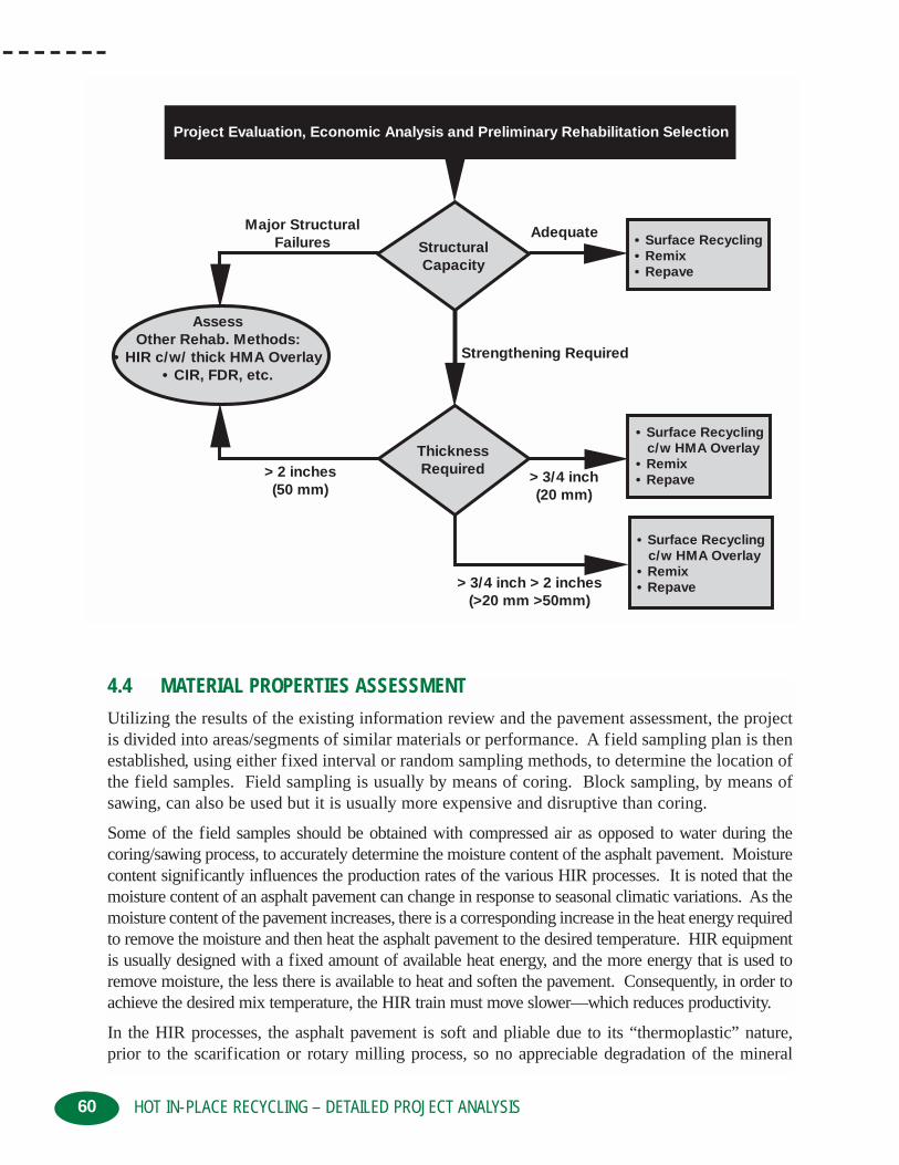
60
4.4 MATERIAL PROPERTIES ASSESSMENT
Utilizing the results of the existing information review and the pavement assessment, the projectis divided into areas/segments of similar materials or performance. A field sampling plan is thenestablished, using either fixed interval or random sampling methods, to determine the location ofthe field samples. Field sampling is usually by means of coring. Block sampling, by means ofsawing, can also be used but it is usually more expensive and disruptive than coring.
Some of the field samples should be obtained with compressed air as opposed to water during the coring/sawing process, to accurately determine the moisture content of the asphalt pavement. Moisturecontent significantly influences the production rates of the various HIR processes. It is noted that themoisture content of an asphalt pavement can change in response to seasonal climatic variations. As themoisture content of the pavement increases, there is a corresponding increase in the heat energy requiredto remove the moisture and then heat the asphalt pavement to the desired temperature. HIR equipmentis usually designed with a fixed amount of available heat energy, and the more energy that is used toremove moisture, the less there is available to heat and soften the pavement. Consequently, in order toachieve the desired mix temperature, the HIR train must move slower—which reduces productivity.
In the HIR processes, the asphalt pavement is soft and pliable due to its “thermoplastic” nature, prior to the scarification or rotary milling process, so no appreciable degradation of the mineral
HOT IN-PLACE RECYCLING – DETAILED PROJECT ANALYSIS
Project Evaluation, Economic Analysis and Preliminary Rehabilitation Selection
StructuralCapacity
• Surface Recycling• Remix• Repave
• Surface Recycling c/w HMA Overlay• Remix• Repave
• Surface Recycling c/w HMA Overlay• Remix• Repave
ThicknessRequired
AssessOther Rehab. Methods:
• HIR c/w/ thick HMA Overlay• CIR, FDR, etc.
Major StructuralFailures
Adequate
Strengthening Required
> 2 inches(50 mm)
> 3/4 inch(20 mm)
> 3/4 inch > 2 inches(>20 mm >50mm)

61
aggregates occurs. Therefore, it is critical that field samples not be obtained by cold planing, witha small milling machine, since this method will result in more degradation of the mineral aggregatesthan will occur in the HIR process. Rather, cores should be used, since they will provide more rep-resentative samples. The larger the diameter of the core, the smaller the ratio of cut surface to volume which corresponds to less degradation in aggregate gradation. Core samples in the order of6 to 8 inches (150 to 200 mm) in diameter are preferred. However, 4 inch (100 mm) diameter corescould be used for some of the laboratory testing such as field density, Marshall Stability, etc. It isimportant that the full depth of the asphalt bound layers be cored in order to assess their condition.
The frequency of field sampling varies with the size of the project, size of the areas of similarmaterials or performance, and the variability of the existing materials, as determined from thereview of existing QC/QA data. Generally, the number of sample locations ranges from 3 to 5 forsmaller, consistent areas, to 20or more for larger, less consistent areas. Samples are obtained ata frequency of approximately one location per 5/8 mile (kilometer) per lane direction. The num-ber of cores obtained at each field sampling location will depend on the number of field samplelocations, the amount of laboratory testing to be performed, and whether or not samples will beneeded for subsequent HIR mix designs. If a 5 point Marshall mix design is to be undertaken, atotal of 18 to 20 cores, 2 inches (50 mm) thick, and 6 inches (150 mm) in diameter or approxi-mately 90 pounds (40 kilograms) of material, is usually required.
The core samples should be carefully examined in order to detect the different pavement layers,previous surface treatments, interlayers, geotextile paving fabrics, specialty mixes, evidence ofstripping, friable or disintegrating mix, retention of excessive moisture, and any tendency todelaminate. Once the cores have been inspected, the observations recorded, and selected coresphotographed, the cores are trimmed to the depth of the anticipated HIR treatment.Representative cores are then tested to determine:
• bulk specific gravity/density
• field moisture content
• asphalt binder content
• aggregate properties including gradation, angularity, etc.
• recovered asphalt binder properties including penetration, absolute and/or kinematic viscosity, and perhaps temperature susceptibility or Superpave PG grading
• Maximum Theoretical Density of the existing mix
• in-situ void properties of the existing mix including Va, VMA, and VFA
4.5 GEOMETRIC ASSESSMENTIn the detailed geometric assessment, determine whether the project:
• requires major realignment, widening or drainage corrections
• contains underground utilities/drainage structures
• requires upgrading of any underground utilities
• contains bridges/overpasses
• needs longitudinal/grade corrections
• requires cross-slope/fall corrections.
HOT IN-PLACE RECYCLING – DETAILED PROJECT ANALYSIS

62
Major realignments, widening or drainage corrections may eliminate HIR, depending on the extentof the reconstruction, but HIR could still be included as a stage in the overall rehabilitation process.
The presence, frequency, and elevation of utility covers (manholes and valves) need to beassessed, particularly in the urban setting. Manholes and valves can be raised or lowered depend-ing on existing elevations, but their presence tends to reduce productivity. Obviously, if anyupgrading of the existing underground utilities is required, it should be undertaken prior to reha-bilitating the roadway surface.
Bridges/overpasses need to be assessed to determine:
• whether an asphalt pavement is present and whether it is to be rehabilitated with the remainder of the project
• depth of existing asphalt pavement
• presence of waterproofing membranes, their depth, and sensitivity to heat
• presence of any specialty waterproofing mixes (latex, polymers, etc.)
• structural capacity to accommodate weight of the HIR equipment
• allowable weight and effect of compaction equipment, particularly vibratory steel drum rollers
HIR equipment generally has fixed treatment widths, although there are some newer modelswhich will allow some variable treatment widths. The HIR treatment width is usually one lane or12 feet (3.7 meters), since typically only the driving lanes are treated. However, full width treatment of the pavement can be undertaken, particularly for wider roadways. Pavements whichare not exactly a whole multiple of the treatment width of the HIR equipment will require someoverlap to ensure full HIR coverage. Ideally, an overlap between adjacent HIR passes of 2 to 6inches (50 to 150 mm) is desired. If the overlaps become significantly larger, there are poten-tially both economic and performance implications, particularly if significant amount of admix or recycling agent is being used in the process.
The HIR process being used also affects the amount of longitudinal and transverse profile corrections which can be practically undertaken. The amount of longitudinal and transverse correction which can be performed with:
• Surface Recycling is minor since little or no admix is added during the process
• Remixing is average but is related to the amount of admix being added, with more correctionbeing possible with higher admix addition rates
• Repaving is above average but is related to the thickness of the integral HMA overlay beingplaced. The thicker the integral overlay, the greater the correction
In some instances, it may be more practical/economic to place a thin HMA preliminary levelingcourse, or reprofile the roadway with a milling machine prior to HIR. If Cold Planing (CP) or apreliminary leveling course is to be used, it must be accounted for in the HIR mix design process.
The HIR equipment is very long, due to the number of pieces in the train. Therefore, roadwaygeometry, particularly in an urban setting, will influence the types of areas which can be treated.The HIR equipment can handle moderate radius turns such as acceleration/deceleration lanes,turning bays, etc., provided there is sufficient room for the equipment to exit the area. Roadwayscontaining “T” intersections cannot be treated all the way to the top of the “T.”
HOT IN-PLACE RECYCLING – DETAILED PROJECT ANALYSIS

63
4.6 TRAFFIC ASSESSMENT
Traditionally, HIR has been utilized on low to medium traffic volume roadways. There is no prac-tical reason why it cannot be used on high traffic volume roadways, particularly for the Remixand Repave processes.
The HIR process minimizes traffic disruptions and user inconvenience due to the short constructiontime, compared to conventional pavement rehabilitation methods. HIR can also be undertaken atnight or in off peak hours to further reduce traffic disruptions.
Depending on the width of the existing roadway, the HIR operation will occupy 1 1/4 to 1 1/2lanes within the HIR construction zone. For narrow roadways, accommodation of large/widetruck or oversized loads will need to be addressed.
On two lane roadways, one-way traffic through the construction zone will need to be maintainedwith appropriate traffic control such as flag people, lane demarcation devices, and/or pilot vehi-cles. Very narrow two lane roadways increase the traffic accommodation difficulties, particular-ly if there is little or no paved shoulder.
Traffic control at intersections and business approaches also needs to be addressed in an urban envi-ronment. Due to the speed of the HIR processes, the intersections and approaches are not out ofservice for very long and traffic is usually controlled with flag people and lane demarcation devices.
4.7 CONSTRUCTABILITY ASSESSMENT
As the HIR equipment is relatively wide and long, overnight parking/storage of the equipment isa concern. A level and wide overnight parking area is required, or the equipment must be allowedto be parked on the side of the roadway overnight—with the use temporary traffic delineationdevices, warning lights and/or temporary signals to direct traffic. The width of the roadway beingtreated will determine whether overnight parking on the roadway shoulder is a viable alternative.
The location/spacing of these parking areas are critical, since a HIR train can treat between 1 1/4to 2 1/2 lane miles (2 and 4 lane kilometers) per day. Typically, parking areas should be on theorder of 2 miles (3 kilometers) apart to reduce the amount of equipment travel during daily mobilization and demobilization. Although the individual pieces of HIR train are very mobile dueto their length, the access to and the parking area have to be relatively level since most HIR equip-ment can easily become high centered.
Clear heights for bridges and underpasses must be checked not only for the HIR equipment butthe admix haul trucks, as well.
Generally, HIR equipment can process to the edge of a curb and gutter section. For straight-facedconcrete sections (with no gutter), a portion of roadway will not be able to be treated. Dependingon the HIR equipment set-up, an area of approximately 8 to 12 inches (200 to 300 mm) in widthcannot be processed. If needed, these areas could be CP prior to HIR, and the area paved byextending the paver screed during the HIR laydown process.
If admix or HMA is required to be added in the HIR process, then the availability of aggregatesand access to an asphalt plant must also be assessed.
HOT IN-PLACE RECYCLING – DETAILED PROJECT ANALYSIS
64
4.8 ENVIRONMENTAL IMPLICATIONS
HIR has the potential to create fugitive emissions in the form of blue or white smoke depending on:
• the type, efficiency, and design of the HIR equipment
• the presence of surface treatments, seal coats, crack sealant, and/or thermoplastic lines
• the ambient conditions including temperature, wind velocity, and direction
New HIR equipment; adequately maintained and operated; prior removal of surface treatments;warm ambient temperatures; and little wind will significantly reduce the risk and/or amount ofpotential fugitive emissions. Fugitive emissions are of increased concern in an urban environment.
As with all rehabilitation construction projects, there will be a certain amount of noise associated withthe process. Typically, due to the speed of the HIR operation and the transient nature of the process,the noise effects will be short term. This issue will have increased concerns in an urban setting.
The possibility of flammable substances near the work site needs to be assessed. In general, thisis not a problem, but overhanging trees and vegetation can be scorched during the HIR operation.The scorching wilts the leaves, causing them to turn brown, but the trees usually remain unharmedas the leaves return the following spring. Deflectors on the exhaust stacks of both the emissioncontrols and the equipment power plants have been used to reduce the amount of scorching tooverhanging vegetation. In critical circumstances, the overhanging vegetation can be trimmedback or covered with protective material to prevent scorching.
Immediately prior to the HIR equipment passing over or near any manholes, catch basins, vaults,etc., they must be checked for the presence of any flammable vapors/gases, and should be clearedby the Fire Authority having jurisdiction within the project area.
4.9 ECONOMIC ASSESSMENT
The expected service lives of the various HIR rehabilitation techniques, when undertaking a life-cycle economic analysis, generally fall within the following ranges:
• HIR Surface Recycling with no subsequent surface treatment . . . . . 2 - 4 years
• HIR Surface Recycling with surface treatment . . . . . . . . . . . . . . . . 6 - 10 years
• HIR Remixing . . . . . . . . . . . . . . . . . . . . . . . . . . . . . . . . . . . . . . . . . 7 - 14 years
• HIR Remixing with subsequent HMA overlay . . . . . . . . . . . . . . . . . 7 - 15 * years
• HIR Repaving . . . . . . . . . . . . . . . . . . . . . . . . . . . . . . . . . . . . . . . . . 6 - 15 * years
Note: * Equivalent to agency’s thick lift HMA service life.
The effectiveness and performance of the various HIR rehabilitation techniques varies fromagency to agency and is dependent on:
• local conditions
• climate
• traffic
• type of technique and quality of materials used
• quality of the workmanship
HOT IN-PLACE RECYCLING – DETAILED PROJECT ANALYSIS

Chapter 5
65
CHAPTER 5: HOT IN-PLACE RECYCLING – MIX DESIGN
Like Cold Recycling (CR) and Full Depth Reclamation (FDR), there is no nationallyaccepted method for undertaking a Hot In-Place Recycling (HIR) mix design. A num-ber of different HIR mix design methods have been used by the various agencies which
include HIR in their pavement rehabilitation strategies. Several of these mix design methodshave been reported in the literature. In general, the philosophy for the HIR mix designs hasbeen to restore the properties of the existing aged asphalt pavement to those of (or close towhat would be expected of) virgin Hot Mix Asphalt (HMA). This approach attempts toaccount for the changes which have occurred in the existing HMA due to time, traffic, and theHIR process itself. For example, the asphalt binder may have age-hardened (oxidized) sincethe HMA was originally placed; the HMA may have undergone densification/reduced fieldair voids due to traffic; or the HIR process may age-harden the asphalt binder prior to theaddition of a recycling agent. This approach has been successful on many projects, but oppor-tunities for additional mix improvements may have been possible.
For example, an asphalt pavement that is 10 years old may be distressed and in need of reha-bilitation due to environmental and traffic effects. If the amount of pavement distress isexcessive for its age, as part of determining whether HIR is a viable rehabilitation alternative,it should be determined whether the distress is due to:
• increased traffic loading above what was originally anticipated
• inferior quality materials being used
• failure to follow the job mix formula
• mix properties outside the acceptable tolerance limits
• reduced lift thickness and substandard field compaction
• failure of the mix to perform as indicated by the original mix design
Using the results of the historical information and material properties assessment, as discussedin Chapters 3 and 4, the mix design engineer should determine whether the original HMA mixdesign was adequate, and whether restoration of the existing HMA pavement is achievable. Ifnot, the mix design engineer should consider upgrading and improving the mix properties dur-ing the HIR mix design process, to account for the shortcomings of the original mix.
An example of upgrading the existing mix would be to modify the gradation of the existingHMA with the addition of virgin aggregate during the HIR process. This could have the effectof improving stiffness to better resist rutting or reducing the total asphalt binder content if itwere determined that the original mix was over-asphalted and contributed to excessive rutting.
The asphalt binder plays a pivotal role in the performance of the asphalt pavement. Recyclingagents or very soft asphalt binders can be used to upgrade the overall quality of the asphaltbinder in the recycled mix. The HIR mix design is the place to recognize the opportunity,through careful evaluation and materials selection, to improve the recycled mix properties andextend the performance of the pavement beyond that originally expected.
HOT IN-PLACE RECYCLING – MIX DESIGN

66
HIR mix designs are more complex than standard virgin HMA mixes. A mix design for a HIRRemix project will have nine variables compared to five for a HMA mix design. The variables inthe mix design for the HIR Remix project will include:
• recycling agent type
• recycling agent source
• recycling agent amount
• virgin aggregate gradation
• virgin aggregate amount
• virgin aggregate source
• new asphalt binder type
• new asphalt binder source
• new asphalt binder amount
The conventional HMA mix design variables include:
• virgin aggregate gradation
• virgin aggregate source
• new asphalt binder type
• new asphalt binder source
• new asphalt binder amount
Consequently, the mix designs take more time and have increased costs. The increased costsinvolved create two questions. How much mix design work can be afforded? What are the con-sequences of not performing a mix design? The owner agency will have to weigh the benefits andrisks associated with conducting no, partial or complete HIR mix designs. When the owneragency is assessing the risks associated with not performing a HIR mix design, considerationcould be given to having different requirements for low traffic volume roadways compared to hightraffic volume roadways. It is noted that very few owner agencies would considerpurchasing/using HMA, without some assurance that a mix design had been undertaken and thatthe HMA meets the requirements of their specifications, regardless of the roadway classificationit would be used on.
5.1 ASPHALT BINDER REJUVENATIONWithin the framework of the HIR mix design, consideration of what mechanisms are affecting theperformance of the original mix, and efforts to correct these deficiencies, in recycled mix, shouldbe undertaken. The rejuvenation of the existing asphalt binder is one key mechanism and thereare several viewpoints on how it should be accomplished. These are summarized as follows:
• Use only a recycling agent to restore/rejuvenate the existing asphalt binder properties. Thisassumes that the recycling agent is effective in combining with the aged asphalt binder dur-ing the HIR process.
• Use a soft, new asphalt binder rather than a recycling agent. This assumes that a recyclingagent may not completely combine with the aged asphalt binder and the soft, new asphaltbinder, combined with the original binder, will result in an “average” binder that is adequate.
HOT IN-PLACE RECYCLING – MIX DESIGN

• Use both a recycling agent and a soft, new asphalt binder in conjunction with a virgin aggregate, to rejuvenate the aged asphalt binder,
• Use recycled mix properties such as resilient modulus, stability, etc., rather than asphaltbinder properties, to determine the final mix selection. This recognizes the uncertainties ofadjusting asphalt binder properties in the laboratory and that the overall recycled mix behaviorreflects the net effect of asphalt binder rejuvenation.
An understanding of the nature of the rejuvenation action on the existing asphalt binder is need-ed in order to understand how to approach the HIR mix design. If one were to carefully examinea highly enlarged portion of an existing HMA, the cross-section would indicate aggregate particles surrounded or coated with an aged asphalt binder, and interspersed with air voids. In theHIR process, the mix is heated, softened, and loosened so that a recycling agent and/or an admixcan be added. Immediately following its addition and through the mixing process, the recyclingagent coats the surface of the existing aged asphalt binder. The recycling agent penetrates theaged asphalt binder at a rate that is dependent on the properties of the aged asphalt binder and onthe properties or reactivity of the recycling agent.
If the recycling agent does not readily penetrate and combine with the aged asphalt binder, it willform a lubricated interface, which can cause instability in the recycled mixture. When this happens during HIR construction, it gives the recycled mix the appearance of being over-asphalted orhaving too much recycling agent. This is a result of assuming the recycling agent and aged asphaltbinder are compatible, and can be completely blended during the time available in the HIR process.
If the conditions are optimum and the recycling agent is compatible with the aged asphalt binder, therecycling agent diffuses into the aged asphalt binder producing a co-mingled material which acts asa single, softer material. The resultant recycled mix looks like virgin HMA and behaves as designed.
During the 1970’s, when mix design methods were being developed for conventional hot recycling,there were concerns that the relatively small amounts of recycling agent being added was not welldispersed in the recycled HMA. The Federal Highway Administration (FHWA) sponsored a project on the degree of mixing/dispersion of recycling agent in recycled mixes, using a uniquetwo-part dye system. The study indicated that the recycling agent was very well dispersedthroughout the final mixture and that effectiveness of the recycling agent was dependent on thetemperature of the materials and the time available for dispersion/diffusion. The amount of diffusion of the recycling agent in the aged asphalt binder dramatically slowed when the recycledmix temperature dropped/cooled or as the time at the elevated temperature was reduced.
The overall effect of adding a recycling agent can be determined by testing the physical proper-ties of both the recovered asphalt binder and/or the recycled mixture. When using the asphaltbinder approach, the aged asphalt binder is recovered from the existing asphalt pavement and itsphysical properties such as penetration, viscosity, Superpave PG grading etc., are determined.The recovered, aged asphalt binder is blended with various percentages of recycling agent, andthen tested to determine the change in physical properties which has occurred at the various recycling agent addition rates. The change in asphalt binder physical properties is an indicationof the amount of rejuvenation which has occurred in the aged asphalt binder.
Alternatively, samples of the existing asphalt pavement can be heated until it has softened suffi-ciently to become pliable or workable. Various amounts of recycling agent are then added, along
67HOT IN-PLACE RECYCLING – MIX DESIGN

68
with any admix, consisting of a virgin aggregate mixed/lightly coated with a new asphalt binder,and the combined materials are then thoroughly mixed into one homogeneous mass. Samples of theasphalt binder in the resultant recycled mix are then recovered and tested to determine its physical prop-erties. The physical properties of the combined asphalt binder are then compared to the original agedasphalt binder in order to determine the amount of rejuvenation which has taken place.
The second approach is to determine the amount of rejuvenation which has occurred in the aged binder,by comparing the physical properties of the mix before and after the addition of the recycling agent,and/or admix. The Hveem stability, and to a lesser extent the Marshall stability, has been shown to besensitive to the addition of various amounts of recycling agent. The physical effects of the soften-ing/rejuvenation of the aged asphalt binder by recycling agent can also be determined by resilient mod-ulus testing. If the resilient modulus is determined by a diametral indirect tension test, most of the load-ing stresses are predominately in tension. This significantly reduces the aggregate effects, comparedto the Hveem and Marshall stability tests. Therefore, the stresses are focused on the asphalt binder andany change in asphalt binder property, i.e., amount of rejuvenation, can be more readily determined.
5.2 MIX DESIGN PROCESSThe HIR mix design process has remained the same for most agencies for a long time. More recent-ly, through the Strategic Highway Research Program (SHRP) program and the development of theSuperpave system, an alternate approach may possibly be applied to HIR mix designs. The overallHIR mix design process, whether traditional or Superpave, involves some or all of the following steps:
• evaluation of the existing HMA including asphalt binder, aggregates, and mix properties
• determining whether the existing asphalt binder needs rejuvenation
• selecting the type and amount of recycling agent
• determining the need for and amount of admix including aggregate gradation, type, andamount of soft, new asphalt binder
• preparing and testing both asphalt binder and mix specimens in the laboratory
• evaluating test results and determining the optimum combination of admix and recycling agent.
No matter which HIR mix design method is used, standard sampling and testing methods such asthe American Association of State Highway and Transportation Officials (AASHTO), AmericanSociety for Testing and Materials (ASTM) or the owner agencies’ adaptation of these standardsshould be followed, whenever possible.
5.2.1 BLENDING CHARTSOriginally, HIR mix designs considered primarily the viscosity of the aged asphalt binder and theamount of rejuvenation required. The flow chart presented in Figure 5-1, indicates the original orblending chart HIR mix design process.
The asphalt binder content and physical properties of the recovered aged asphalt binder, from theintended depth of recycling, establish the uniformity of the pavement to be recycled and are usedto estimate the type and quantity of the recycling agent needed. There are three basic purposesfor using a recycling agent, including:
HOT IN-PLACE RECYCLING – MIX DESIGN

69
• restore the aged asphalt binder properties to a consistency level appropriate for constructionpurposes and end use of the recycled mix
• provide sufficient additional binder to coat the existing mix and any virgin aggregate added
• provide sufficient asphalt binder to satisfy the mix design requirements
HIR recycling agents are generally hydrocarbon materials with chemical and physical propertieswhich restore aged asphalt binders to the desired specifications. Soft asphalt binders, specialty/pro-prietary products or even some types of asphalt emulsions can act as recycling agent. Soft asphaltbinders are usually less expensive than specialty products but they are not as efficient at rejuvenation.They also need to be added to a carrier such as the virgin aggregates, as opposed to being directlyapplied to the recycled mix. In order to achieve their intended purpose recycling agents must be:
• easy to disperse in the recycled mix
• compatible with the aged asphalt binder to ensure that syneresis or exudation of the paraffins from the existing asphalt binder does not occur
• able to re-disperse the asphaltenes in the aged asphalt binder
• capable of altering the properties of the aged asphalt binder to the desired level
• resistant to excessive hardening during hot mixing to ensure long-term durability
• uniform/consistent from batch to batch
• low in volatile organic compounds or contaminants to minimize smoking and volatile loss during construction
HOT IN-PLACE RECYCLING – MIX DESIGN
Figure 5-1: Blending chart design flow chart
Obtain Representative Field Samples
Extract, Recover Aged Asphalt Binder, and Determine:~ Asphalt Binder Content
~ Penetration~ Viscosity
Use Viscosity Blending Chart to Determine Type and Amount of Recycling Agent Required to Rejuvenate Aged Asphalt Binder
Finalize Recylcing Agent Selection and Application Rate
Make Field Adjustments to Recycling Agent Application Rate Based on Recylced Mix Appearance and QC/QA Results during HIR Construction

70
The quantity of recycling agent required is determined using a blending chart/viscosity nomograph and procedures such as those contained in American Society for Testing and Materials(ASTM) D 4887 “Preparation of Viscosity Blends for Hot Recycled Bituminous Materials.”Similar types of blending charts are also available from the various recycling agent supplierswhich are specific to their individual products.
The percentage of recycling agent required to meet the target viscosity is initially determined ona weight basis. The target viscosity for the rejuvenated asphalt binder is selected by the owneragency and is dependent on the project environment, anticipated traffic, past performance of theexisting pavement, etc. Usually, the target viscosity is selected to be close to the asphalt binderproperties that were observed when the roadway was originally constructed unless the originalasphalt binder properties were the source of the poor pavement performance.
Some owner agencies prefer to use the penetration value to determine whether the existing asphaltbinder needs to be rejuvenated during the HIR process. The appropriate penetration values are usedin place of the viscosity values in the specifications and during the selection of the recycling agent.
For some owner agencies or for very low traffic volume roadways, the determination of recycling agenttype and amount by means of the blend chart would mark the end of the HIR mix design process.
It is noted that not all recycling agent and aged asphalt binders are compatible. Some owner agen-cies may want to prepare and test laboratory samples of the recovered aged asphalt binder andrecycling agent in order to confirm that the target viscosity has been achieved. If the target vis-cosity has not been met then other trial blends are prepared using different proportions of the samerecycling agent or with a different recycling agent, until the target viscosity has been achieved.The asphalt binder content and the relative density of the pavement to be recycled, together withthe recycling agent application percentage, is used to determine the field recycling agent appli-cation rate in gallons per square yard (litres per square meter). The mix design would then becompleted and construction would proceed.
Use of the viscosity blending chart mix design method usually provides a reasonable but slightly highestimate of the amount of recycling agent needed. Hence, field adjustment in the amount of recyclingagent being added is usually required. Field adjustments would be made based on the visual appear-ance of the recycled mix and/or on the results of QC/QA testing of the recovered asphalt binder.
Use of blending charts does not assess the effect that adding the recycling agent has on the recycled mix, including void properties, stability, resilient modulus, water sensitivity, workabili-ty, etc.. For local or lower traffic volume roadways, changes in these properties may not have aneffect on field performance, but as the roadway classification or as traffic volumes increase, theseitems should be addressed.
5.2.2 TRADITIONAL / COMPREHENSIVE
The more comprehensive HIR mix designs consider not only the rheological properties of theasphalt binder but also the recycled mix properties. The following flow chart, presented in Figure5-2, indicates the more comprehensive HIR mix design process.
This HIR mix design flow chart may appear to be exceedingly complex but it actually is a logical, easy to use approach. As a starting point, the steps outlined in the flow chart, should befollowed in order to address the significant factors that impact on the recycled mix performance.
HOT IN-PLACE RECYCLING – MIX DESIGN

71HOT IN-PLACE RECYCLING – MIX DESIGN
Figure 5-2: Comprehensive mix design flow chart
Make Field Adjustments Basedon QC/QA Test Results During
HIR Construction
No
Yes
Yes
No
Determine:• Moisture Content• Density• Maximum Theoretical Density• Mix Void Properties• Stability• Resilient Modulus
Obtain Representative Field Samples
Are All Properties
Acceptable?
Are All Properties
Acceptable?
Evaluate Test Results forRecovered Asphalt Binder and
Recycled Mix Properties
Prepare Sample Mixtures at Various RAP, RA, VirginAggregate, and Virgin Asphalt Binder Contents
Determine:• Maximum Theoretical Density• Recovered Asphalt Binder Properties
– Penetration– Viscosity– Temperature Susceptibility– Superpave PG Grading
Determine:• Density• Void Properties• Stability• Resilient Modulus• Moisture Sensitivity
Cure and CompactMixtures
Finalize Mix Design and EstablishJob Mix Formula
Evaluate Most Promising Mixturefor Rutting and Fatique Resistance
• Assess Need for Asphalt Binder Rejuvenation• Select Recycling Agent (RA) Type and Amount• Assess Need for Corrective Aggregates• Assess Need for, Type, and Amount of Soft Virgin Asphalt Binder• Select RA, Virgin Aggregate, Asphalt Binder
Determine:• Aggregate Gradation• Angularity• Polish Value• Abrasion Resistance• Bulk Specific Gravity• Petrographic Number
Extract and Recover the Asphalt Binder and MineralAggregates
Determine:• Asphalt Binder Content• Penetration• Viscosity• Temperature Susceptibility• Superpave PG Grading

72
Some of the data may already be available through the detailed project analysis outlined inChapter 4. It is recognized that there are several approaches that can be used to arrive at an appropriate HIR mix design, and with experience, some of the steps could be eliminated.
Extracting and recovering the aged asphalt binder and mineral aggregates is a convenient way toanalyze the components of the existing HMA. The Abson method of asphalt binder recovery isusually preferred since it has the least effect on the properties of the asphalt binder but other recognized methods can also be used. Variations or special considerations may need to be used,particularly if the existing pavement contains polymers, rubber, etc. As a minimum the penetrationand viscosity of the recovered asphalt binder should be determined. Additional properties of therecovered binder such as temperature susceptibility and/or Superpave PG grading could be undertaken, depending on owner agency preference and project specific requirements.
The gradation of the mineral aggregate is required in order to determine whether the existingHMA meets the owner agency gradation specifications for recycled mixes. A number of owneragencies have increased or modified gradation requirements for recycled mixes, compared to vir-gin HMA. The modified gradation specification limits reflect the inherent variability whichoccurs with existing pavement and that in the HIR process 100 percent of the existing materialwill be recycled.
A small amount of aggregate degradation can be expected during the HIR process. The amount ofdegradation that occurs is dependent on the type of HIR process being used, on the type of HIR equip-ment being used, and on the workmanship of the contractor. Generally, the amount of aggregate degra-dation is small and is comparable to what occurs during the coring process. The amount of aggregatedegradation can be exacerbated if rotary milling being used in the HIR process and the treatment depthexceeds the depth of heat penetration needed to adequately soften the existing pavement.
In addition to gradation, the angularity of the existing aggregate should be determined using theowner agency’s existing procedures. It is now widely accepted that aggregate angularity plays asignificant role in determining whether a mix will be susceptible to rutting. The overall angularityof the existing aggregates may need to be improved in order to account for the effects of increasedwheel loading. Other aggregate properties should also be determined, particularly if the existingpavement distress is related specifically to the aggregate, i.e., friction number. If the bulk specific gravity of the aggregates is not known from the historical data, it should be determinedin order to be able to calculate the recycled mix void properties.
The moisture content, relative density, and Maximum Theoretical Density of the existing HMA,needs to be determined in order to calculate the void properties of the existing pavement. Theexisting void properties will influence the type and amount of recycling agent and admix whichmay be required. Additional mix properties such as Hveem or Marshall stability and/or resilientmodulus can be subsequently used to assess the effectiveness of the recycling agent.
If the existing asphalt binder has aged excessively, rejuvenation will be required. The amount ofrejuvenation will depend on the amount of aging which has occurred and on the owner agency’srequirements for new asphalt binder or recycled mixes. Traditionally, viscosity or penetration hasbeen used as the target property for assessment of rejuvenation. The target property is usuallyselected to be the midpoint in the grade of asphalt binder—which would normally be used for theproject’s climatic conditions, traffic conditions, and construction method, i.e., will the recycledmix be overlaid?
HOT IN-PLACE RECYCLING – MIX DESIGN

Some agencies have recognized that the properties of the asphalt binder in a recycled mix can beharder or stiffer than conventional virgin mixes, without compromising performance or inducingadditional distress. Hence, the degree of rejuvenation of the aged asphalt binder needs to beassessed on a project-by-project basis and should be consistent with the owner agency’s experience on other recycling projects. It is also noted that the same target properties for recycled and conventional mixes may not result in the same field performance.
If the existing aggregate gradation needs to be modified to meet the current aggregate specifica-tions, then blending with a virgin aggregate will be required. For virgin aggregates which havenot been used previously, their physical properties such as petrographic number, abrasion resistance, polish value and stripping resistance must be considered. This also applies to the existing pavement aggregates, if the pavement distress is aggregate related.
The amount of virgin aggregate that can be added is limited by the capacity of the existing HIRequipment and is usually less than 30 percent. Coarse, highly angular aggregates are usuallyadded to improve stability, rutting resistance, and friction number. Clean, fine aggregates are usu-ally added to improve mix void properties such as Va, VMA, and VFA. In order to reduce costs,the virgin aggregates selected for use should be readily available. Heating of the virgin aggre-gates is recommended since it improves productivity. Pre-coating of the virgin aggregates withan asphalt binder helps to reduce dust, assists in coating of the coarse aggregates and can help inrejuvenation of the aged asphalt binder.
Preliminary selection of the recycling agent is based on previous experience, to ensure compati-bility, and on blending charts to determine an approximate quantity. The addition rate will needto be adjusted, particularly if a soft asphalt binder is used with the virgin aggregates, so that thecombined asphalt binder has the desired physical properties.
Preparation of samples at various contents of recycling agent, virgin aggregate, new asphaltbinder, and existing pavement or RAP can be undertaken. No universally accepted testing protocolfor the preparation of the samples is available. However, owner agency procedures for conven-tional HMA and hot recycling mix designs, such as the Marshall or Hveem methods, could beadapted with some slight modifications. The laboratory conditions should model HIR field conditions as closely as possible.
The representative sample of the existing pavement, consisting of 6 or 8 inch (150 or 200 mm)diameter cores, trimmed to the intended depth of recycling, should be very carefully dried andheated in order that additional hardening of the aged asphalt binder does not occur. This is usually achieved by heating the cores in lightly closed containers in a non-forced air oven and byminimizing the time the RAP is at elevated temperatures. Past experience with numerous HIRprojects around North America, has indicated that the HIR process, without the addition of anyadmix or recycling agent, results in a:
• decrease in penetration of approximately 20 to 25 percent
• increase in kinematic viscosity of approximately 150 to 200 percent
Hence, the hardening of the aged binder that occurs in the mix design process should approximatethe hardening which happens during construction. Usually, the hardening which occurs in the laboratory is in excess of that which occurs in the field. Hence, a fixed amount of recycling agentis required to overcome a hardening which is generally not needed during construction.
73HOT IN-PLACE RECYCLING – MIX DESIGN

The virgin aggregate and new asphalt binder are prepared in the same manner as for a virgin HMAmix design and is usually called “admix.” The mixing temperature for the admix should be determined based on the viscosity of the new asphalt binder and is typically 170 +/- 20 mm2/s (approximately 0.17 +/- 0.02 Pa•s for an asphalt binder density of 1.00 g/cm3). The use of this mix-ing viscosity results in excessively high temperatures for the RAP due to the high viscosity of the agedasphalt binder. Consequently, a mixing temperature of 10°F (5°C) above an arbitrary selected recycled mix compaction temperature, usually 250 to 265°F (120 to 130°C), is commonly used.
Once both the RAP and admix have stabilized at the mixing temperature they are combined andpreliminarily mixed. The recycling agent, if used, is then added and the mixing continues until ahomogenous recycled mix is achieved. Mixing time should be as short as possible but sufficient-ly long so as to model the mixing time which occurs in the field and to provide a uniform mix.Ideally, five different combinations of RAP, admix, and recycling agent should be assessed. Thedifferent combinations should be sufficiently different from one another to provide a measurabledifference in physical properties but not so different as to make comparisons difficult. The visualappearance of the recycled mix, at the completion of the mixing time, is assessed and recorded.
The recycled mix should then be cured in a lightly closed container in a non-forced air oven, set atthe compaction temperature. There is no standardized curing time but it is usually between 30 min-utes to one hour after the recycled mix has reheated to the compaction temperature. The curing peri-od should be long enough to permit the recycling agent to diffuse through the aged asphalt binderbut not overly long as to overestimate what happens in the field. Care must also be taken with thelaboratory recycled mix to ensure that excessive hardening of the rejuvenated asphalt binder doesnot occur. Some owner agencies may choose to cure the recycled mix after it has been compacted.
Aliquot samples of the cured recycled mix are tested for Maximum Theoretical Density, the asphaltbinder is recovered and tested to determine the degree of rejuvenation which has taken place.
The compaction of the recycled mix could be by any method the owner agency chooses but it isusually by either the standard Marshall or Hveem method. The compaction level is adjusted tocorrespond to the anticipated project traffic. The compacted recycled mix is cooled and testedlike conventional virgin HMA samples to determine the relative density, stability, flow, resilientmodulus, moisture sensitivity, Va, VMA and VFA. The amount of testing performed will dependon the capabilities of the owner agency, the size, and location of the project.
The test results at the various recycling agent, admix, and RAP contents are assessed for confor-mance with the specifications. As noted previously, the amount of rejuvenation of the agedasphalt binder should be assessed on a project-by-project basis and be consistent with the owneragency’s experience on other recycling projects. Recycled mix properties such as Va, VMA, VFA,etc., have traditionally been compared to those required of virgin HMA.
It is known that central plant hot recycled mixes have higher relative densities and lower air voidsthan equivalent virgin mix, even though the RAP contents are usually less than 50 percent. Thesecentral plant hot recycled mixes have been shown to have the same if not superior performance toconventional virgin HMA. HIR mixes use significantly higher ratios of RAP, so the effects ofincreased relative density and lower air voids are even more pronounced. The original pavementwas usually constructed at or near the optimum asphalt content for the aggregate gradation, andthe addition of recycling agent to rejuvenate the aged asphalt binder can lead to even more air void
74 HOT IN-PLACE RECYCLING – MIX DESIGN

75
reduction. The traditional HIR mix design approach was to add a virgin aggregate to dry the recy-cled mix out and/or open up the voids in order to achieve conventional HMA air void contents.The net effect is an overall reduction in asphalt content and reduced asphalt film thickness, bothof which have the effect of reducing long-term durability of the recycled mix.
Recognizing this, several owner agencies are using a different set of criteria or mix properties todesign and accept HIR recycled mix. They have recognized that equivalent performance to virginHMA can be achieved with HIR mixes even though they have different physical properties. In mostcases, a significant reduction in recycled mix air voids can be accepted without affecting perform-ance. Each owner agency is encouraged to evaluate the recycled mix properties which can be accept-ed while still maintaining performance. Development of these unique recycled mix properties will,in most cases, permit additional asphalt binder rejuvenation (although care must be taken to ensurethat the rejuvenated binder is not too “soft”) or lower threshold acceptance limits on the recoveredasphalt binder, a reduction in the amount of admix required, and a reduction in overall HIR costs.
Some owner agencies may want to conduct some additional testing to assess the rutting andfatigue resistance of the most promising or economic mix. This would normally be reserved forrecycled mixes which would be intended as a surface mix, such as in the Remix process or forprojects with very high design traffic. Conventional HMA rutting and fatigue resistance testmethods could be used but it is noted that experience is limited in translating the test results intoacceptable HIR recycled mix performance.
Once the analysis has been completed, the HIR mix design can be finalized and the job mix formu-la established. The recycled mix with the optimum physical properties and acceptable economicsshould be selected. The submitted HIR mix design should include the following information:
• asphalt binder content of the existing pavement for the intended recycling depth
• rheological properties of the asphalt binder in the existing pavement treatment depth
• gradation and aggregate properties of the portion of the existing pavement to be recycled
• gradation and aggregate properties of any virgin aggregate that is required
• type and amount of new asphalt binder required to be added to any virgin aggregate
• type and amount of recycling agent
• rheological properties of the asphalt binder in combined recycled mix
• gradation and aggregate properties of the combined recycled mix
• recycled mix void properties and physical properties
As with all mix designs, the job mix formula establishes the most promising or likely combina-tion of materials based on laboratory conditions. Once construction begins, the actual recycledmix should be sampled and tested. Based on the results of the field testing, adjustment or finetuning of the job mix formula should be undertaken.
Existing pavements with excessive age-hardening of the asphalt binder or having sever strippingmay present an insurmountable challenge for the HIR mix designer. If this occurs, either an alternate rehabilitation method should be used, or the mix can be accepted at reduced properties—knowing that a corresponding reduction in performance or service life will occur.
HOT IN-PLACE RECYCLING – MIX DESIGN

76
5.2.3 SUPERPAVE
The Superpave technology/system is a product of SHRP that was conducted between 1988 and1993. Superpave is an acronym that stands for SUperior PERforming PAVEments. Additionalresearch/implementation work is continuing with the Superpave system. The principle outcomeof SHRP was the performance-based or performance-graded (PG) specifications for asphaltbinder, and the Superpave volumetric mix design process using the Superpave GyratoryCompactor (SGC).
As of this writing, no documentation or confirmation exists that indicates that the Superpave tech-nology is completely applicable to HIR mixes. Research has been conducted on RAP contents ofup to 40 percent, so it is unknown whether the same assumptions and trends will hold for RAPcontents of 70 to 100 percent found in HIR mixes.
In the SHRP Superpave PG system of classifying asphalt binder, the Dynamic Shear Rheometer(DSR) is used to characterize the viscous and elastic components of the behavior of asphaltbinders at high and intermediate temperatures. At normal pavement service temperatures, mostasphalt binders behave like viscoelastic materials, i.e., they simultaneously act like an elastic solidand a viscous fluid.
The DSR measures the complex shear modulus G* (G star) and phase angle s (delta) of the asphaltbinder at given temperatures and frequencies of loading. The complex modulus can be consideredto be the total resistance of the asphalt binder to deformation when repeatedly sheared and consistsof two components G’ (G prime) and G’’ (G double prime) which are related to each other by thephase angle s. G’ is the storage modulus or the elastic (recoverable) behavior of the asphalt binderwhile G’’ is the loss modulus or the viscous (non-recoverable) part of the asphalt binder’s behavior.
Originally, SHRP used only new asphalt binders and HMA mixes. More recently, additionalresearch work on modified asphalt binders and recycled asphalts/mixes with up to 40 percentRAP has been conducted. The following is a summary of the current Superpave design approachfor conventional hot recycled mixes.
The Superpave specifications were designed to improve the performance of HMA pavements byselecting asphalt binders which do not contribute to:
• tenderness during laydown by requiring the G*/sin s of the unconditioned asphalt binder tobe less than 1.0 kPa
• permanent deformation by requiring the G*/sin s of the rolling thin film oven test (RTFOT)residue be greater than 2.2 kPa
• fatigue cracking by requiring the G* sin s of the RTFOT and pressure aging vessel (PAV)residue to be less than 5 MPa
• low temperature cracking by requiring the creep stiffness value (S) and slope value (m) ofthe RTFOT + PAV residue to be less than 300 MPa and greater than 0.30, respectively.Alternatively, if the creep stiffness value is between 300 and 600 MPa the result of theDirect Tension Test (DTT) can be used, in lieu of the creep stiffness, but the direct tensiontest must have a minimum of 1.0 percent strain at failure. The creep stiffness and slope val-ues are determined by the Bending Beam Rheometer (BBR).
Since the above noted physical properties are dependent on temperature, any asphalt binder canmeet the requirements given the appropriate test temperature. Therefore, the Superpave PG
HOT IN-PLACE RECYCLING – MIX DESIGN

77
system is based on specified test temperatures, with the required physical property remaining con-stant for all PG grades. The Superpave asphalt binders are graded according to a high servicetemperature, a low service temperature, and an intermediate temperature of 25°C. For example,a PG58-34 (PG 58 minus 34) asphalt binder is expected to meet the tenderness and permanentdeformation requirements up to a high temperature of 58°C, and the low temperature crackingrequirement down to a temperature of –34°C. The PG58-34 asphalt binder is also expected tohave adequate intermediate performance between the high and low temperatures by meeting thefatigue cracking requirement at a temperature of 25°C. Therefore, two tests are required to deter-mine the high temperature value, one test is needed to determine the intermediate value, and threetests are needed to determine the low temperature value of an asphalt binder.
This means that as many as six Superpave blending charts are needed in order to determine thesix test parameters needed for Superpave PG grading of any recycled mix asphalt binder.Research, to date, has been confined to the high and intermediate temperature values with no pub-lished data for the low temperature parameters. This reduces the number of required blendingcharts to three. The two for the high temperature are called “high temperature sweep blendingchart – 1.0 kPa” and “high temperature sweep chart – 2.2 kPa” and one for the intermediate tem-perature parameters, called “intermediate temperature sweep blending chart – 5 MPa.” However,the issue of low temperature performance has not been addressed.
Blending charts need to be developed for blending aged asphalt binder, and new asphaltbinder/recycling agent in the same way as was outlined in Section 5.2.1. The asphalt grade isbased on the Superpave PG grading, rather than viscosity, used previously. The asphalt binder testparameters obtained from the DSR are used in place of the viscosity or penetration blendingcharts. The temperatures at which the various Superpave parameters are achieved, i.e., G*/sin s= 1.0 kPa, are determined by performing a temperature sweep (testing at different temperatures)at different percentages of aged and new asphalt binder. These temperature results are plotted andan “iso-stiffness curve” is produced. Any point on the iso-stiffness curve represents a possiblecombination of aged and new asphalt binder which meets the particular Superpave parameter.
Blending charts determine the temperature value required for the aged and new asphalt binder to havea specific stiffness, as opposed to conventional viscosity blending charts which determine the vis-cosity (stiffness) of the aged and new asphalt binder at specific temperatures. Therefore, temperaturevalue is plotted on the Y-axis of the temperature sweep blending charts, as opposed to viscosity valueon the viscosity blending charts, the percentage of new asphalt binder is plotted on the X-axis.
Data indicate that when the high temperature blending charts are plotted on a linear X-Y graph, theiso-stiffness curve approaches a straight line. Therefore, the high temperature sweep blending chart– 1.0 kPa can be constructed by plotting the two temperatures at with the aged asphalt binder andthe virgin binder/recycling agent is 1 kPa, and drawing a straight line through the two points. Thesame holds true for the high temperature sweep blending chart – 2.2 kPa. However, the iso-stiffnesscurve for the intermediate temperature sweep blending chart is not a straight line but curves down-ward. Intermediate temperature sweep blending charts constructed assuming that the iso-stiffnessline is straight will slightly under-predict the amount of new asphalt binder/recycling agent required.
According to the Superpave system, both high temperature sweep blending charts should be used.However, data indicates that the amount of new asphalt binder/recycling agent predicted by usingonly one high temperature sweep blending chart does not change significantly from those
HOT IN-PLACE RECYCLING – MIX DESIGN

78 HOT IN-PLACE RECYCLING – MIX DESIGN
predicted by using both high temperature sweep blending charts. Therefore, only one blendingchart need be used to determine the amount of new asphalt binder/recycling agent or converselythe amount of aged asphalt binder that can be used in a recycled mix. The high temperature sweepblending chart – 1.0 kPa is normally used since it avoids running the time-consuming RTFOT test.
Construction of high temperature sweep blending charts involves conducting temperature sweeptests on both the aged and new asphalt binders in order to determine the temperature at whichG*/sin s = 1.0 kPa. The inconvenience of running temperature sweep tests can be eliminated byconstructing a “Specific Grade Blending Chart”. The Y-axis of a specific grade blending chart isin log-log, similar to viscosity/penetration blending charts. By plotting G*/sin s, on a log-logscale on Y-axis versus percent new asphalt binder on the X-scale which is linear, a near linear relationship or straight line is obtained. Therefore, the information needed to construct a specif-ic grade blending chart are the G*/sin s of the unconditioned new asphalt binder and the agedasphalt binder at only the specific test temperature.
Use of the intermediate temperature sweep blending chart predicted unusually high percentagesof aged asphalt binder which is inconsistent with the field experience with recycled HMA.Hence, the intermediate temperature sweep blending chart is currently not used to determine themaximum amount of aged asphalt binder which can be used in a recycled mix.
In its place, a three tiered system of selecting the PG grade of the new asphalt binder is being usedfor hot recycled mixes. The tiers are as follows:
• Tier 1: If the amount of RAP is equal or less than 15 percent, the selected PG grade of thenew asphalt binder should be the same as the Superpave required PG grade.
• Tier 2: If the amount of RAP is more than 15 percent but equal to or less the 25 percent, theselected PG grade of the new asphalt binder should be one grade below, i.e., softer, in both thehigh and low temperature grade which would be required by the Superpave system.
• Tier 3: If the amount of RAP in more than 25 percent, use the specific grade blending chartto select the high temperature grade of new asphalt binder. The low temperature grade shouldbe at least one grade lower than the binder grade specified by the Superpave system.
Research conducted as part of NCHRP 9-12 indicates that the high stiffness RAP (PG88-4 afterrecovery) used in the study had a greater effect on the low temperature properties of the blendedasphalt binder than the medium and low stiffness RAP. This data suggests that limiting RAP values noted above could possible be modified depending on the low temperature stiffness of therecovered RAP asphalt binder.
A recycled asphalt binder would always meet the G*/sin s = 1.0 kPa minimum, for unconditionedasphalt binders and the G*/sin s = 2.2 kPa minimum, for RTFOT residue, at any RAP content pro-vided the appropriate high temperature grade of new asphalt binder is used. This happens since theaddition of RAP increases the G*/sin s values of the unconditioned and RTFOT residue. If the newasphalt binder is one or two grades below the specified Superpave PG requirement, a procedure isneeded to determine the maximum amount of new asphalt binder, to increase the high temperaturestiffness of the recycled asphalt binder, above the minimum values specified by Superpave. Therecommended blending chart, to determine the maximum amount of new asphalt binder, is the“specific grade blending chart,” for the Superpave required PG grade and a 1.0 kPa stiffness line.

79HOT IN-PLACE RECYCLING – MIX DESIGN
A procedure is needed to determine the minimum amount of new asphalt binder that is required.Data has indicated that use of a 2.0 kPa maximum stiffness value for the G*/sin s, at high tem-perature, to determine the minimum amount of unmodified new asphalt binder which should beused. An example of a specific grade blending chart is as indicated in Figure 5-3.
The Superpave system uses a gyratory compactor to densify the HMA samples and produce avolumetric mix design base for the anticipate traffic. Trial mixes of the HIR recycled asphaltusing the SGC following the Superpave mix design procedures with various recycling agent andadmix addition rates.
Various agencies have initiated programs to assess the Superpave volumetric mix design in lieu ofthe Marshall or Hveem methods. To date, no documentation or confirmation data exists to indicate whether the Superpave volumetric mix design method is suitable for designing HIR mixes.Owner agencies will have to establish their own evaluation criteria based on a combination of laboratory and field trials.
Specific Grade Blending Chart
% Virgin Asphalt BinderO 25 5O 75 10O
O.1
1
10
100
G*/
sin
(d
elt
a)
at
ºC
, k
Pa
2.0 kPa Stiffness line (min. virgin asphalt binder)
1.0 kPa Stiffness line (max. virgin asphalt binder)
Figure 5-3: Specific grade blending chart


Chapter 6
81HOT IN-PLACE RECYCLING – CONSTRUCTION
CHAPTER 6: HOT IN-PLACE RECYCLING -CONSTRUCTION
The equipment used in Hot In-Place Recycling (HIR) has many different configurationsdepending on the HIR process, i.e., Surface Recycling, Remixing or Repaving, whereand who manufactured the equipment, and the particular contractor undertaking the proj-
ect. Surface Recycling was the first HIR process to be developed and it has its origins in the1930’s, when the first rudimentary machines were introduced. In the late 1970’s and early1980’s, the HIR equipment had a significant transformation, resulting in the Repave andRemix HIR processes being developed. HIR equipment and technology are continually evolv-ing and being upgraded, with the use of hot air/low infrared heating and a mixing drum, in lieuof a pugmill, being two of the more recent innovations.
Equipment trains used in each of the HIR processes have some similarities and some significantdifferences. The key is to focus not so much on the configuration of a particular piece of equip-ment as to understand the function or functions performed by the individual pieces of equipment.
Some common preparatory measures should be undertaken prior to HIR, regardless of theHIR process being used. These include:
• detailed safety or hazard assessment
• development of a detailed traffic control plan
• repair of any areas with drainage problems
• repair of any isolated base failure areas
• leveling of excessive deformations, either by cold planing or by preliminary leveling, toprovide a satisfactory working platform
• ensuring the pavement surface is clean and free of deleterious materials such as dirt, etc.
• detailed project analysis, as outlined in Chapter 4, and preparation of a mix design andjob mix formula, as outlined in Chapter 5
Each HIR construction process will be discussed in more detail in the subsequent sections.
6.1 SURFACE RECYCLINGSurface Recycling has been known by a number of different names over the years includingheater-scarification, heater-planing, reforming, resurfacing, etc., and has been in fairly com-mon use since the mid-1960’s. Compared to the other HIR processes Surface Recycling isthe most fundamental/least technologically complex process. It primarily consists of:
• drying and heating the upper layers of the existing pavement
• scarifying the heated/softened asphalt pavement
• adding a recycling agent, if required by the mix design and job mix formula
• mixing the loose recycled mix
• spreading and placing the recycled mix with a free floating screed
• compacting the recycled mix using conventional HMA rollers and procedures

82 HOT IN-PLACE RECYCLING – CONSTRUCTION
No virgin aggregate or HMA is added during the Surface Recycling process, so modification ofthe existing asphalt pavement is restricted to the rejuvenation of the aged asphalt binder.Production rates for Surface Recycling vary widely depending on:
• ambient temperatures and wind conditions
• characteristics of the asphalt pavement being treated
• moisture content of the existing pavement
• the number and heat output of the equipment
Production rates from as low as 5 to as high as 50 feet per minute (1.5 to 15 meters per minute)can be experienced.
Drying and heating/softening of the existing asphalt pavement is performed with one or more pre-heating units. Early preheating units used open or direct flame to dry and heat the asphalt pave-ment, but this method has now been replaced with indirect radiant and/or infrared heating. Themove to indirect radiant and infrared heaters was made to reduce undesirable fugitive emissionsand damage to the asphalt binder. Most heaters are now fueled by propane or a similar com-pressed gas, although the new hot air/low infrared heating units use diesel fuel.
The preheaters operate in close proximity to one another to maximize the heat penetration. Three variables affect the transfer of heat to the asphalt pavement consisting of:
• maximum temperature of the heat source
• pavement surface temperature/ambient conditions
• length of time pavement surface is exposed to the heat source
In order to heat the asphalt pavement without significant damage to the existing asphalt binder,either lower heat sources or longer heating times are required. Therefore, to heat the pavementsurface in a more controlled manner, the length of time the reduced heat source is exposed to thepavement needs to be increased. This can be accomplished by slowing the rate at which the heatsource moves over the pavement or increasing the number of heat sources. Slowing the heatsource increases costs by reducing production rates. Consequently, contractors optimize produc-tion by using additional preheaters, as indicated in Figure 6-1.
The number of preheating units is not as important as the length of the heating areas/hoods oneach preheater, assuming the same heat output per unit of length. For example, two preheaterswith 26 foot (8.0 meter) heating hoods will have a longer total heat exposure time than three preheaters with 16 feet (5.0 meter) heating hoods.
The preheating units should increase the temperature uniformly across the treatment area or “mat”without any hot spots or scorching of the existing pavement. The temperature of the scarified mate-rial, after mixing, should be an average of at least 230°F (110°C) and no more than 300°F (150°C).
Following immediately behind the preheaters is a heating/scarification unit, as indicated in Figure 6-2.

83HOT IN-PLACE RECYCLING – CONSTRUCTION
Figure 6-1: Surface Recycling preheaters
Figure 6-2: Heating and scarifying unit

84 HOT IN-PLACE RECYCLING – CONSTRUCTION
This unit adds the final heating and then scarifies the softened asphalt pavement. Traditionally,the softened asphalt pavement is scarified or loosened by one or more rows of spring loaded lev-eling rakes/scarifying teeth/tines, as indicated in Figure 6-3.
The scarifying tines on some units may be pneumatically or hydraulically activated in order to min-imize fracturing of the coarse aggregate in the underlying cooler pavement. They are also capableof overriding or being lifted over obstacles such as manhole covers, concrete structures, etc.
The depth of scarification usually specified for the surfacing recycling process is between 3/4 and1 1/2 inches (20 and 40 mm) with 1 inch (25 mm) being most common. The scarification tinesare normally in alignment with the finished pavement surface to ensure a uniform depth of scar-ification. Obviously, due to different hardness and depth of heat penetration of different portionsof the pavement, particularly with rutted or distorted pavements, some variation in scarificationdepth may occur.
Scarification depth can be controlled somewhat by changing the spring tension, adjusting thepneumatic/hydraulic pressure on the tines or varying the forward speed of the equipment. Withproper operation of the preheaters and heater/scarification unit, variations in scarification depthwill be kept to a minimum, typically on the order of 3/16 inch (5 mm).
In addition to the scarifying tines, some scarifying units are being equipped with small diameterhot milling drums. Such drums are equipped with replaceable tungsten carbide tipped millingtools to uniformly loosen the heated/softened asphalt pavement to a level plane. There may bemore than one hot milling drum to cover the treatment width, each being operated independent-ly of the other. In this way, they can be lifted over obstacles such as manhole or utility covers.
Figure 6-3: Spring loaded scarifying tines

85HOT IN-PLACE RECYCLING – CONSTRUCTION
Figure 6-4: Recycling agent addition
Experience indicates that oxidation/hardening of the asphalt binder occurs at a faster rate inthe upper levels of a pavement, compared to lower levels. Surface Recycling permits theintroduction of a recycling agent in the portion of the pavement that it can do the most good,as indicated in Figure 6-4.
The recycling agent, if required, is usually added to the loosened asphalt pavement by a comput-er-controlled system which is linked to the forward operating speed of the equipment. Valvesprovide positive control of the recycling agent as the equipment starts and stops. The recyclingagent application rates vary, depending on the condition of the aged asphalt binder, the type ofrecycling agent being used, and the requirements of the mix design. Recycling agent applicationrates of from 0 to 0.5 gallons per square yard (0 to 2 litres per square meter) can be easily added.
In some operations, the recycling agent is added by the heater/scarifier unit, while in others it isadded by a separate piece of equipment, as indicated in Figure 6-5.
The recycling agent is contained in an onboard storage tank, and is usually heated so that it canbe applied close to the highest temperature recommended by the recycling agent supplier. Thisenhances the dispersion of the recycling agent through the loosened/scarified material. If therecycling agent is an asphalt emulsion, it will absorb some of the heat energy of the scarifiedmaterial in order to heat and evaporate the emulsion water. Hence, the temperature of the scari-fied material may need to be increased a few degrees to account for the heat loss during the emul-sion moisture evaporation.
Once the recycling agent has been added to the scarified material, they are then mixed into ahomogeneous recycled mixture. Mixing is usually performed with a set of standard augers, as
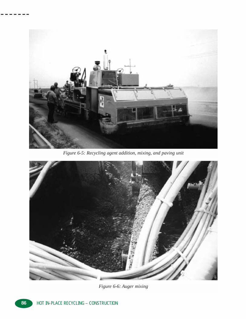
86 HOT IN-PLACE RECYCLING – CONSTRUCTION
Figure 6-5: Recycling agent addition, mixing, and paving unit
Figure 6-6: Auger mixing

87HOT IN-PLACE RECYCLING – CONSTRUCTION
Figure 6-7: Free floating screed on scarification unit
indicated in Figure 6-6. The recycling agent is sometimes added prior to the asphalt pavementbeing scarified, in which case the scarifying tines not only loosen the asphalt pavement but mixit, as well. In some rare applications, the recycling agent is added in a fog coat type application,after the asphalt pavement has been scarified, placed, and compacted.
Surface Recycling is normally used to eliminate surface irregularities, cracks, and to restore thepavement surface to a uniform grade line and cross-section. Hence, leveling and spreading of therecycled mix is undertaken with a free floating screeding unit. Material is moved into any lowareas by an auger in front of the screed prior to the screeding unit leveling and imparting the ini-tial compaction to the recycled mix. Some contractors use a modified HMA paver to place therecycled mix, as was indicated in Figure 6-5, while other use a free floating screed attached tothe heater/scarification unit, as indicated in Figure 6-7.
The screeds are generally manually controlled in order to ensure adequate material is always availablein front of the screed. The screeds are usually heated and vibrate to initially compact the recycled mix.Once the recycled mix has been screeded into place, it is compacted with conventional HMA rollers.
Traditionally, a rubber-tired pneumatic roller is used to perform the breakdown rolling while adouble steel drum vibratory roller is used for finishing rolling, as indicated in Figure 6-8. Somecontractors use static steel rollers for compaction. Since the existing asphalt pavement below therecycled mix is warm, a thermal bond is provided with the recycled mix and there is more thansufficient time for the rollers to achieve the required degree of compaction.
Once the compaction has been completed and the pavement cools, the HIR process is completedand roadway can be then be opened to traffic.

88 HOT IN-PLACE RECYCLING – CONSTRUCTION
Figure 6-8: Compaction equipment
Figure 6-9: Surface Recycling before and after

89HOT IN-PLACE RECYCLING – CONSTRUCTION
On some low traffic volume roadways, the recycled mix can be left as the wearing course.However, more commonly it subsequently has a surface treatment applied or a thin lift HMAoverlay is placed. Placement of a thin lift HMA overlay is possible since the recycled roadway islevel, rejuvenated, and crack free, as indicated in Figures 6-9 and 6-10.
When the wearing course is subsequently placed on the recycled mix surface the process is commonly called “multiple pass” Surface Recycling.
The HMA overlay can also be of a significant thickness if strengthening of the roadway structure isrequired. Usually there is a delay between completion of the Surface Recycling and the applicationof the HMA overlay, in the multiple pass Surface Recycling process, permitting the HMA overlaycontractor to proceed at higher production rates, resulting in decreased costs. If the specificationsrequire that the HMA overlay be placed immediately on the recycled mix, the paving contractormust proceed at the same rate as the HIR contractor. This usually increases the overall costs.
6.2 REMIXING
Remixing is used when:
• Significant modification of the physical properties of the existing asphalt pavement must beundertaken to correct specific pavement distresses. Changes to aggregate gradation, aggre-gate abrasion/friction number, asphalt binder content, asphalt binder rheology, mix stability, andmix void properties can be made with the appropriate selection of admix and recycling agent.
Figure 6-10: Surface Recycling before and after

90 HOT IN-PLACE RECYCLING – CONSTRUCTION
• The recycled mix is to function as the wearing course for higher traffic volume applications,
• A modest amount, i.e., less than 3/4 inch (20 mm), of pavement strengthening is required.
Remixing is classified into either single or multiple stage methods. In the single stage method, theexisting asphalt pavement is sequentially heated/softened and then the full treatment depth is scarifiedat one time. Additional heating of the scarified material, could be undertaken in some equipmentsetups, but no more scarification of the existing pavement takes place, as indicated in Figure 6-11.
Treatment depths for the single stage method are generally between 1 and 2 inches (25 and 50mm) with 1 1/2 inches (40 mm) being most common.
In the multi stage method the existing asphalt pavement is sequentially heated/softened and scar-ified in a number of layers usually between two and four. The scarified material from the firstlayer is placed in a windrow to permit heating/softening of the underlying layer, as indicated inFigure 6-12. In some equipment setups, the scarified material is picked up and carried over thesubsequent heating units.
Treatment depths for the multiple stage method are between 1 1/2 and 3 inches (40 and 75 mm)with 2 inches (50 mm) usually being most common.
The single stage Remixing method was developed in the late 1970’s and early 1980’s in Europeand Japan, while the multi-stage Remixing method was developed in North America in the late1980’s and early 1990’s. Steady improvements to the Remixing equipment, since their initialdevelopment, have been made in the areas of:
• increased mix temperatures
• deeper treatment depths
• adjustable treatment widths
• improved productivity
• quieter operation
• improved air quality
• increased capabilities to add recycling agent and admix
• better control of recycling agent and admix addition
HIR Remix trains are currently being used on projects around the world and, whether single ormultiple stage, primarily consists of:
• drying and heating the upper layer of the existing pavement
• scarifying the heated/softened asphalt pavement
• adding a recycling agent and admix or HMA, as required by the mix design and job mix formula
• thoroughly blending/mixing into a homogenous recycled mix
• spreading and placing the recycled mix with a free floating screed
• compacting the recycled mix using conventional HMA rollers and procedures
Production rates for Remixing vary widely, depending on the same variables listed for SurfaceRecycling plus the amount of admix being added and the Remix treatment depth. Production ratesfrom as low as 5 to as high as 35 feet per minute (1.5 to 10.7 meters per minute) can be experienced.

91HOT IN-PLACE RECYCLING – CONSTRUCTION
Figure 6-11: Single stage Remixing train
Figure 6-12: Multiple stage Remixing train

92 HOT IN-PLACE RECYCLING – CONSTRUCTION
Drying and heating/softening of the existing asphalt pavement is performed with one or more preheating units in the same fashion as for Surface Recycling.
Scarifiers and/or hot milling drums loosen the softened material which is then augured towardsthe center of the unit. The scarifying/hot milling units usually have “moldboards” to help collectthe reclaimed material and are depth and slope controlled by automatic sensors operating off ashort reference ski or matching shoe, as indicated in Figure 6-13. Some equipment setups willpermit variable heating and scarification widths of between 11 to 14.5 feet (3.5 to 4.5 meters).
In the single stage method, the loose material is directed into a mixing chamber consisting of pugmill orin some equipment setups a mixing drum. A variation to this process are setups where further heatingand drying, in a heater stirrer unit, is performed prior to the loose material entering the mixing chamber.
In the multiple stage method, the loose windrowed material passes below the next heating unit or itis picked up and carried over the heating bed of the next unit by a slat conveyor. The slat conveyorhas a variable speed control in order to match the forward speed of the HIR train. The sequence iscontinued until the required Remix treatment depth is achieved and all the loose material enters themixing chamber. The average temperature of the loosened mix, as it enters the mixing chamber,should be between 250 to 300°F (120 and 150°C).
In all equipment setups, the measured amount of recycling agent, admix or virgin HMA is added priorto the mixing phase. The exact location in which the various materials are added may vary, but it isalways at or prior to the mixing chamber. Addition of the recycling agent is most often applied asearly as possible in the process in order to maximize the dispersion time with the aged asphalt binder.
Figure 6-13: Hot milling drum and matching shoe

93HOT IN-PLACE RECYCLING – CONSTRUCTION
Figure 6-14: High fluids content in first layer of a multi stage project
If the roadway being treated with the Remix process has a surface chip seal and/or a significantamount of recycling agent is being added, particularly for the multiple stage method, the fluidcontent of the first layer of loosened material can become very high and the material may tend to“slump” or act as a slurry in the windrow, as indicated in Figure 6-14. The slumped material isthen re-windrowed, combined with the subsequently heated/scarified layers, admix, and thenthoroughly mixed prior to placement. The recycled mix, in Figure 6-14, was placed in 1995 andhas had excellent performance since then.
The admix or virgin HMA is supplied to the HIR train via standard tandem axle haul trucks to ahopper in front of one of the units prior to the mixing chamber, as indicated in Figure 6-15.
The admix and recycling agent are added to the loosened material by a computer controlled systemwhich is linked to the forward operating speed of the HIR train, in order to provide reliable and precisecontrol. Valves and relays provide positive shut off of the recycling agent and admix as the equipmentstarts and stops. The admix and recycling agent application rates vary, depending on the condition ofthe aged asphalt, the type of recycling agent being used, and the requirements of the mix design.Recycling agent application rates of from 0 to 0.5 gallons per square yard (0 to 2 litres per squaremeter) can be easily added. The admix application rate is limited to a maximum amount of about 30percent by weight of recycled mix or 110 pounds per square yard (55 kilograms per square meter).

94 HOT IN-PLACE RECYCLING – CONSTRUCTION
Figure 6-15: Haul truck supplying admix to HIR train
Figure 6-16: Remixing unit and integrated screed

95HOT IN-PLACE RECYCLING – CONSTRUCTION
Figure 6-17: Conventional HMA paver placing recycled mix
Mixing with augers and/or hot milling drums has been used, but the most successful Remixprocesses use a twin shaft pugmill or rotary drum mixer to uniformly and completely mix the recycled material. As with Surface Recycling, the recycled mix is placed with a free floating screedattached to the mixing unit or with a separate HMA paver, as indicated in Figures 6-16 and 6-17.
The screeds are usually of the heated, vibratory or tamping bar type and are equipped with automatic slope and grade controls similar to those found on modern HMA pavers, as indicatedin Figure 6-17. The warmed underlying pavement is usually between 120 and 180°F (50 and80°C) and the recycled mix is usually between 230 and 265°F (110 and 130°C) after being placed,resulting in a thermal bond between the two layers. In addition, the heating beds normally extendbeyond the scarification width by 4 to 6 inches (100 to 150 mm) which heats and softens the adja-cent material. This provides a thermally integrated bond between the existing asphalt pavementand the recycled mix resulting in a seamless longitudinal joint which is more resistant to environmental and traffic effects.
If the project contains any utility covers or infrastructure they are paved over and then raised tograde, as indicated in Figure 6-18.
Compaction is achieved with conventional HMA rollers usually consisting of a rubber-tired pneumatic roller for breakdown and a double drum steel vibrating roller for finishing, as indicat-ed in Figure 6-19, although some contractors use static steel rollers.
Rubberized chips seals and asphalt pavements containing crumb rubber and polymer modifiedasphalt binders have all been remixed without significant difficulties. Increased heating requirements,

96 HOT IN-PLACE RECYCLING – CONSTRUCTION
Figure 6-18: Raising water valve after remixing
Figure 6-19: Compaction of recycled mix

97HOT IN-PLACE RECYCLING – CONSTRUCTION
the affinity of the rubber/polymer for the rubber tires of the HIR and compaction equipment, andthe possibility of increased fugitive emissions are difficulties which can be overcome.
Emission control systems have been developed to control the gaseous hydrocarbons generated inthe HIR process. These systems include some method of collecting the fumes generated duringthe heating process and incinerating them at very high temperatures in a combustion chamber orafter burner. The after burner reduces the hydrocarbons/combustible materials to primarily carbon dioxide and water vapor. The emission systems are designed to reduce or eliminate theopacity, irritants, and particulates to levels which comply with the air pollution standards. HIRtrains equipped with emission control systems have met the very strict emission regulations ofWashington and California, including the Los Angles area.
6.3 REPAVINGRepaving is used when:
• Surface Recycling and/or Remixing alone cannot restore the pavement profile or surfacerequirements, such as friction number
• When a conventional HMA overlay operation is not practical
• A very thin HMA or specialty mix which is to act as the wearing course is required, and/or
• A significant amount, i.e., 2 inches (50 mm) or less, of pavement strengthening is required
The application of very thin HMA overlays, on the order of 1/2 inch (12.5 mm), is possible in theRepave process provided the appropriate mix is used. This is significantly thinner than the 1 to1 1/2 inches (25 to 40 mm) minimum overlay thickness which can be placed with conventionalHMA equipment. In addition, since the overlay can be a very thin layer of specialized mix or aHMA they can be placed more economically. Specialty mixes such as Open Graded FrictionCourses, polymer modified mixes, etc., can be used.
Repaving is classified into either single or multiple pass methods. In the single pass method theexisting asphalt pavement is recycled and the last unit in the HIR train also places an integraloverlay of new HMA/specialty mix on the screeded but uncompacted recycled mix, so that bothlayers are compacted at one time, as indicated in Figure 6-20.
In the multiple pass method, the last unit in HIR train screeds and places the recycled mix. A sep-arate paver then follows immediately behind and places the conventional HMA/specialty mix onthe uncompacted recycled mix. Both the recycled mix and the new overlay material are then com-pacted as one thick lift, as indicated in Figure 6-21.
Treatment depths of the existing asphalt pavement vary, depending on which method is beingused. Treatment depths therefore vary between 1 and 2 inches (25 and 50 mm). The depth oftreatment of the existing asphalt pavement is also related to the thickness of the integral HMAoverlay or specialty mix which needs to be placed. A combined thickness of integral overlay andunderlying recycled mix greater than 3 to 4 inches (75 to 100 mm) can result in increased place-ment, compaction, and smoothness difficulties. Typically, a 1 to 2 inch (25 to 50 mm) recycleddepth and a 1 to 2 inch (25 to 50 mm) integral overlay thickness is used.
The single pass Repaving method was developed in the late 1950’s and early 1960’s in NorthAmerica. Steady improvements to the repaving equipment have been made since then.
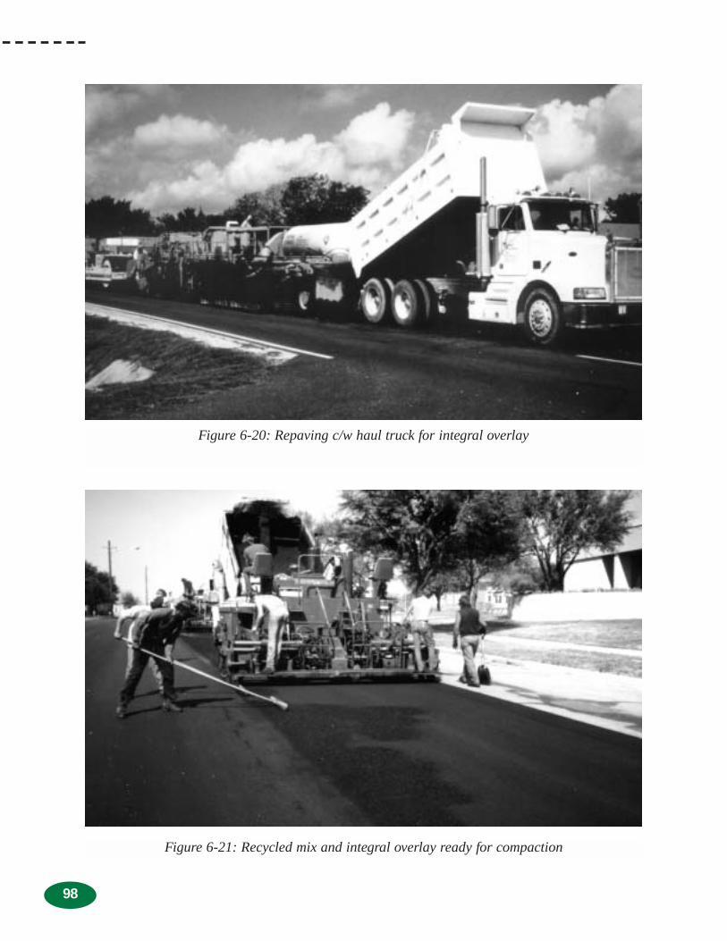
98
Figure 6-20: Repaving c/w haul truck for integral overlay
Figure 6-21: Recycled mix and integral overlay ready for compaction

99HOT IN-PLACE RECYCLING – CONSTRUCTION
Repaving trains are also currently being used on projects around the world, and whether single ormultiple pass, primarily consist of:
• HIR of the existing pavement
• simultaneously or sequentially placing the new HMA/specialty mix
• compacting the recycled mix and new material together using conventional HMA rollersand procedures
Production rates for Repaving are the same as what was previously indicated for the SurfaceRecycling and Remixing processes.
Equipment, procedures, and issues for the recycling of the existing asphalt pavement have beenidentified in the Surface Recycling and Remixing sections and are applicable to the Repavingprocess. The new HMA/specialty mix is supplied to the last unit in the HIR train or to the con-ventional paver by standard tandem axle haul trucks. If the HIR train is to place the integral over-lay in the single step method, the new material is conveyed from a hopper through the equipmentand is distributed on top of the already screeded recycled mix, in front of the second or finishingscreed, as indicated in Figure 6-22.
In the multiple pass method, the new HMA is supplied directly into the hopper of the conventionalHMA paver and is placed using standard HMA construction procedures.
The screeding units are usually of the heated, vibratory or tamping bar type, and are equipped withautomatic slope and grade controls similar to those found on modern HMA pavers. The warm,underlying, untreated asphalt pavement, the hot recycled mix and the hot new materials are all ther-mally bonded to one another during the compaction process. Once again, compaction is achievedwith conventional HMA rollers, usually consisting of a rubber-tired pneumatic roller for breakdownand a double drum steel vibrating roller for finishing, as was indicated previously in Figure 6-19.
RollerSecond Screed
CompactingReprofilingLevelingRejuvenating
ScarifyingHeating
Second MixerFirst Screed
New Mix
First Mixer
RejuvenatorScarifierLPG
Infrared Heater
Figure 6-22: Admix movement through Repave equipment

100 HOT IN-PLACE RECYCLING – CONSTRUCTION
Figure 6-23 indicates the before and after condition of a roadway which had been treated with theHIR Repave process, consisting of 1 1/2 inches (40 mm) of Remix and 1 1/2 inches (40 mm) ofan integral HMA overlay.
Figure 6-23: HIR Repave before and after

Chapter 7
101HOT IN-PLACE RECYCLING – SPECIFICATIONS AND INSPECTIONS
CHAPTER 7: HOT IN-PLACE RECYCLING –SPECIFICATIONS AND INSPECTION
As with all roadway construction processes, two key steps are required to ensure the sat-isfactory construction and performance of a Hot In-Place Recycling (HIR) project. Firstis the development of an adequate and equitable set of specifications, and second is the
inspection of the HIR project during construction to ensure that the intent of the specificationshas been achieved.
In the Hot Mix Asphalt (HMA) industry, two common types of specifications are currentlybeing used. These consist of the traditional, recipe or method specifications and end productor end result specifications.
Method specifications generally describe, in varying amounts of detail, the materials, equip-ment, and procedures to be used by the contractor in order to obtain the desired quality or per-formance of the recycled mix/project. A key component of the method specification is theneed to include detailed descriptions of all variables or contingencies which may affect thequality or performance of the recycled mix.
End Result specifications set limits on a number of physical properties of the finished prod-uct, while most of the material selection, equipment used, and construction methods are left tothe contractor. A key component of the end result specifications is the need to know what phys-ical properties and the limits for these physical properties that are critical to the long-term performance of the recycled mix.
There are advantages and disadvantages with each type of specification.
The advantages of method specifications include:• owner agency has a great deal of control over the equipment, construction methods, and
materials used on the project
• for a knowledgeable owner agency, with extensive experience with the various HIRprocesses, writing the specifications will be lengthy but straightforward
• material assessment, selection of the materials to be used, and the mix design are under-taken by the owner agency.
• full time inspection of the construction process and Quality Control/Quality Assurance(QC/QA) testing are undertaken by the owner agency
• owner agency makes the major decisions with respect to project management
• the majority of the risk is borne by the owner agency which generally reduces the overallHIR costs
The disadvantages of method specifications include:
• contractor has little input into construction equipment, methods or quality
• there is little or no incentive to provide higher than the required quality or to advanceinnovative alternatives

102 HOT IN-PLACE RECYCLING – SPECIFICATIONS AND INSPECTIONS
• specifications for existing equipment and materials do not readily accept new or differentequipment and materials
• some end result or acceptance requirements are usually included such as aggregate gradationlimits, construction tolerances, percent compaction, smoothness, etc.
• confrontations arise when not all aspects of the specifications or acceptance requirements areachieved
• when acceptance requirements are not achieved, the owner agency can reject and not pay fordeficient material, even if it has some value or, as is usually the case, accept and pay full pricefor substandard material
The advantages of end result specifications include:
• contractors are given responsibility for the construction process and control over those itemswhich they are in a better position to control, i.e., quality
• materials selection and mix designs are undertaken by the contractor
• QC is the responsibility of the contractor and QA is the responsibility of the owner agency
• end result expectations are clearly outlined, along with how these expectations will be measured in an objective and unbiased manner
• new/more advanced equipment and materials are more readily accepted and encouraged
• the physical properties of the finished product are defined along with payment factors thatare linked to the quality, including incentives for increased quality
• acceptance is based on the well-established principles of Statistical Quality Assurance(SQA), including an appeal mechanism
• confrontations are eliminated since the course of action is defined when superior or substandard quality is achieved
The disadvantages of end result specifications include:
• difficulties in determining which physical properties are required to ensure quality/long-termperformance of the finished product
• difficulties in determining what limits should be used on the required physical properties ofthe finished product. This is more problematic when the variability of the existing pavementmaterials is high, as 100 percent of the existing material is recycled in the HIR process, andthe contractor has no control over its consistency
• not all end result requirements can be practically defined or specified, necessitating the inclu-sion of good construction/paving practice requirements which tend to be more method orient-ed, such as lift thickness, mix compaction temperatures, raking of joints, etc.
• some transition difficulties can be expected when moving from method specifications, wherethe owner agency provides all the technical expertise, to end result specification, where thecontractor is expected to have considerable technical expertise
• confrontations can arise when QC and QA test results are not in agreement
• increased budget uncertainty, since it is more difficult to predict final construction costs as theamount of additional payments for increased quality is unknown
• significant change in approach for owner agencies, from having direct control in the construc-tion process to ensuring quality is being achieved through an observational/acceptance role

103HOT IN-PLACE RECYCLING – SPECIFICATIONS AND INSPECTIONS
The trend in the HMA industry is towards greater reliance on end result specifications, with someowner agencies introducing performance warranties in conjunction with end result specifications.Implementation of end result specifications in the HMA industry is a slow process, has had somedifficulties, and not all jurisdictions have or are adopting end result specifications.
Many projects that have been appropriate candidates for HIR have been completed with methodspecifications, and these projects are performing well. Although not as many HIR projects havebeen completed with end result specifications, most have been very successful and are performingwell. The type of specification used for any given HIR project ultimately rests with the owneragency. The decision will be heavily influenced by the owner agency’s approach to HMA speci-fications and their experience with the HIR process.
7.1 METHOD SPECIFICATIONSWhen it has been decided that a method specification will be used for HIR projects, a number ofitems are usually included within the specifications. These include:
• general description
• definitions and terminology
• HIR method to be used
• material requirements
• equipment requirements
• construction methods
• inspection and QC/QA
• acceptance requirements
• measurement and payment
The general description, usually one or two short paragraphs long, introduces the project, the HIRprocess, and construction methodology in broad terms. It may or may not identify other sections ofthe owner agency’s existing specifications that are related to the HIR specifications and the variousdocuments which need to be submitted by the contractor.
Some method specifications include a section outlining the terminology and definitions used with-in the specifications. The terminology and definition section is more often included when HIR isbeing used for the first time and not everyone is familiar or comfortable with the terms used.
A more detailed section indicating which HIR method is to be used, either Surface Recycling,Remixing or Repaving (with Surface Recycling or Remixing) is included within the specifica-tions. In addition, the requirement for single or multiple pass Surface Recycling or Repaving andsingle stage or multiple stage Remixing is also indicated within this section.
The section on materials includes requirements for the recycling agent, virgin aggregate, newasphalt binder, and HMA. The recycling agent required is usually indicated by a specific prod-uct, an equivalent product, existing owner agency recycling agent specifications or other pub-lished recycling agent specifications such as those contained in the American Society for Testingand Materials (ASTM). The virgin aggregates, if added in the Remix process, are usually requiredto meet the owner agency’s existing aggregate specifications. The new asphalt binder is also

104 HOT IN-PLACE RECYCLING – SPECIFICATIONS AND INSPECTIONS
usually required to meet the existing requirements of the owner agency. Any HMA used in themultiple pass Surface Recycling, the Remix or Repave process is usually specified as one ofHMA mix types which would normally be used by the owner agency.
In a method specification, as part of the mix design process, the owner agency selects the:
• recycling agent type and source
• recycling agent application rate
• aggregate source and gradation
• asphalt cement source and grade
• admix (the combination of virgin aggregates and new asphalt binder) addition rate
Therefore, the materials section is primarily to indicate to the contractor the types of materials thatwill be used on the project, as opposed to requiring the contractor to select the particular materi-als to be used.
The section on equipment requirements contains a fair amount of detail and can be rather lengthy.It includes details for all equipment from the HIR preheater units through to the placement andcompaction equipment. The specifications can include requirements for:
• age or operating condition of the equipment
• types of heating units and heating fuel
• minimum heater output, number of heating units or minimum equipment processing capabilities
• emission controls
• type of scarification/rotary milling
• method, control, and accuracy of recycling agent addition
• method, control, and accuracy of admix addition
• blending and uniformity of the recycled mix
• type of spreading and leveling equipment
• number and type of compaction equipment
In addition, requirements for pre-approval or acceptance of the equipment, prior to use, by theowner agency is usually included. In some instances, the specifications include the requirementfor the proposed HIR equipment to undertake a “test strip” in order for the owner agency to evaluate and approve the equipment, contractor and/or workmanship.
Construction methods included in the specifications are usually the existing owner agency spec-ifications or industry publications for good paving practices. There will be some additionalrequirements which address such issues as:
• pavement surface preparation prior to HIR
• pre-heating width
• minimum and maximum pavement surface temperature prior to scarification/rotary milling
• HIR processing width and depth
• minimum and maximum mix temperature at laydown

105HOT IN-PLACE RECYCLING – SPECIFICATIONS AND INSPECTIONS
• minimum mix temperature during compaction
• number and type of rollers required for compaction
• weather conditions at the time of HIR construction
• transition requirements at the start and end of HIR sections
• longitudinal and transverse joint requirements
• checking of underground utilities for flammable vapors
• adjustment of manholes, catchbasins, valves and other roadway castings
• local, county, regional, state and federal regulatory requirements
• site cleanup
With method specifications, the owner agency is in control of the construction process and thereforeneeds to have full time inspection and testing. The owner agency personnel on the project must havethe experience to evaluate the test results and authority to make field adjustments to the HIR process.
The specifications usually outline the frequency of sampling and the testing methods that will beused. Wherever possible, these should be published industry standards, such as the AmericanAssociation of State Highway and Transportation Officials (AASHTO) or ASTM methods or theowner agency’s own adaptation of these procedures. Since the owner agency is essentially in con-trol of the construction process, the QC and QA testing are usually one and the same, andincreased inspection is used to control the HIR process.
A section of the specifications, outlining the acceptance requirements for the HIR work, is alsoincluded. The acceptance requirements include such things as:
• treatment depth
• recycled mix temperature
• recycled mix void properties
• percent compaction
• smoothness
• workmanship
• obvious defects
Some of these are obviously end result requirements but they have traditionally been included inmethod specifications.
The final section deals with measurement and payment issues for the HIR project. The specifi-cations usually outline how items will be measured such as HIR by the square yard (square meter),recycling agent by the gallon (litre), and admix by the ton (tonne). In addition, the specificationsindicate what is to be included in each of the payment items.
HIR payment typically includes full compensation for all labor, equipment, tools and incidentalsnecessary for the completion of the HIR in accordance with the specifications, including surfacepreparation (sweeping roadway only), heating, scarification/rotary milling, addition of recyclingagent and admix, mixing, placement, compaction of the recycled mix, and site clean up. Theowner agency usually has specific compensation items for mobilization/demobilization and fortraffic accommodation, but these are sometimes included within the HIR payment item.

106 HOT IN-PLACE RECYCLING – SPECIFICATIONS AND INSPECTIONS
Recycling agent and admix payment is for the amount incorporated into the HIR mix and includescompensation for supply, delivery, storage, handling, and addition of the recycling agent and admix.
Compensation for other items such as localized asphalt pavement repairs prior to HIR, repairingor raising roadway castings, supply and placement of HMA leveling prior to HIR, cold planing tocorrect roadway irregularities prior to HIR, HMA used as the wearing course, etc., are made asindividual payment items.
Special Provisions, appended to the HIR specifications, are used to indicate specific projectrequirements such as:
• limits of work
• construction schedule, staging or limitation on hours of work
• trucking requirements
• traffic accommodation requirements
• interaction and cooperation with other contractors
• parking and storage of equipment
• existing roadway material properties
• mix design information
• any other site-specific requirements
The degree to which these various issues are addressed within the specification and the special provi-sions will depend on the owner agency’s experience with HIR and the type of HIR process to be used.
7.2 END RESULT SPECIFICATIONS
When it has been decided that an end result specification will be used for HIR projects, a num-ber of issues will need to be addressed within the specifications. In order to develop an end resultspecification there must be a clear understanding of the end product properties required and howthese properties can be quantified or measured. On the other hand, the end result specificationsshould be kept as simple and straight forward as possible.
As with conventional HMA, there are a number of end product properties which could be speci-fied for HIR mixes. These include:
• aggregate characteristics
• aggregate gradation
• asphalt binder content
• recovered asphalt binder rheological properties
• recycled mix void properties
• recycled mix stability and flow properties
• recycled mix friction number and rutting properties
• field compaction
• smoothness
• workmanship, etc.

107HOT IN-PLACE RECYCLING – SPECIFICATIONS AND INSPECTIONS
Like conventional HMA, the HIR mix needs to be stiff, durable, uniform, and smooth in order tohave acceptable long-term performance. To be stiff, the recycled mix has to be adequately com-pacted. To be durable, it must have adequate void and asphalt binder rheological properties. Tobe uniform, it must be free of segregation and surface defects. To be smooth, it must have anacceptable California Profilograph Index (PrI), International Roughness Index (IRI) or similarmeasurement. When the HIR pavement has met these six end product properties, it will have anacceptable service life.
End result specifications need to incorporate SQA testing procedures into the specifications.SQA is an unbiased method used to make decisions related to areas of specification development,construction, and inspection. It gives the person in charge a definite degree of confidence in thedecision to accept a given product. SQA has three principle components:
• random sampling
• process control
• acceptance procedures
Statistical concepts for QA in construction are based on the laws of probability and the premisethat all parts of the whole have an equal chance of being chosen as the sample to be tested.
The sampling locations must be selected by random or stratified random sampling techniques,with some practical limitations, to ensure that the sample location is indicative of the materialbeing evaluated. An example of a practical limitation would be a minimum distance from the startor stop of a day’s production.
Process control or QC is the sole responsibility of the producer/contractor. Quality is controlled,within the required specification limits, so that all of the material produced will be accepted atfull contract price.
Acceptance procedures are based on lot-by-lot testing, for the purpose of assessing the quality ofthe materials or workmanship. A lot is a uniquely defined, homogeneous portion of material orwork about which a decision has to be made. A lot is normally divided into a minimum numberof sub-lots and one sample, chosen/located at random, is obtained and tested from each sub-lot.Typically, a lot is one day’s production and there are usually five sub-lots per lot.
All test results should be reviewed for anomalies which may have occurred due to faulty testingequipment, improper sampling, improper testing procedures and/or calculations. If an anomalyis found, the sub-lot should be retested. The results from each sub-lot are then averaged to deter-mine the results for the lot.
The key to end result specifications is the inclusion of payment adjustment factors, which link thepayment to the quality of the final product. Payment adjustment factors ideally reflect theincreased or decreased performance of the as-constructed asphalt pavement related to theincreased or decreased quality provided. The establishment of the link between quality and pave-ment performance is difficult to quantify, even for conventional HMA. However, the relationshipbetween physical properties of the asphalt pavement and pavement performance are generallywell established and intuitively obvious, for conventional HMA. They may not be as intuitivelyobvious for HIR pavements.

108 HOT IN-PLACE RECYCLING – SPECIFICATIONS AND INSPECTIONS
Good engineering judgement should be used to establish the initial end result specifications andpayment adjustment factors, based on previous experience, achievable results, and geographicconsiderations. In the HIR process, it must be recognized that the contractor has absolutely nocontrol over 70 to 100 percent of the material being used, i.e., the existing asphalt pavement.
Payment adjustment factors should include an equivalent incentive/bonus to provide superiorquality as the penalties imposed for substandard quality. The bonus will be factored back into thecontract prices, by quality orientated contractors, with the net effect of reduced overall projectcosts and increased long-term performance.
Payment adjustment factors need to be linear or curvilinear, as opposed to stepped, so that smallchanges in test results do not result in large changes in the payment adjustment factor. This alsoreflects the performance of asphalt pavements which are linear or curvilinear in nature.
End result specifications and payment adjustment factors need to be reviewed on a yearly basis inorder to take advantage of new information and performance of HIR roadways constructed underthe end result specifications.
Finally, the end result specifications should contain an appeal mechanism to reduce the risk ofhaving an acceptable product penalized or rejected in cases where the lot test results do not trulyreflect the actual value of the lot, due to random chance in the sampling process. In general, theQA test results are correct but they may not be fully representative of the material/workmanshipin the lot. The appeal mechanism should take this into account.
7.3 SPECIFICATION LIMITS
Applying or adapting HMA job mix tolerances for HIR mix properties such as asphalt content,gradation, voids, etc., will not be reasonable, practical or cost-effective for most HIR projects.The job mix tolerances and QA plan have to be developed on a project specific basis.
As was indicated in Chapter 5, it is recognized that conventional hot plant recycled HMA tendsto have higher densities and lower mix void properties when RAP contents of less than 50 percentare used. These effects are even more pronounced with HIR mixes which contain 70 to 100 per-cent RAP. It is also widely accepted that HMA mixes containing RAP have the same, if not bet-ter, performance than conventional HMA.
The existing asphalt pavement was originally constructed at or near the optimum asphalt bindercontent in order to met the conventional HMA void and stability requirements. Over time theasphalt binder may have aged or oxidized somewhat and there may have been some aggregatedegradation, but in general the original optimum asphalt binder content should still be applicable.If a recycling agent is used to rejuvenate the aged asphalt binder, it has the effect of increasing thebinder content which in turn results in a reduction of mix air voids. If conventional HMA voidrequirements are applied to the HIR mix, it would be considered to be too low in void propertiesand corrective action would be needed. The corrective action has historically been to reduce thebinder content of the mix with the addition of virgin aggregates. The virgin aggregates dry outthe mix and the mix void properties are raised into the range acceptable for HMA. Although theHIR mix void properties are within the acceptable HMA range, the net effect is to reduce the

effective asphalt binder content of the mix with a corresponding reduction in asphalt binder filmthickness. Therefore, the existing asphalt pavement which had an appropriate film thickness forlong-term durability, has had the film thickness reduced by trying to make the HIR mix have thesame void properties as a conventional HMA. The ultimate effect of the reduced film thicknesswill be reduced durability and a reduced service life.
Consequently, when setting the specification limits for the recycled mix, it is important to recog-nize that equivalent physical properties between a conventional HMA and a HIR mix do not nec-essarily mean equivalent field performance. More often, it means reduced field performance forthe HIR mix. The goal of the specifications should be to obtain equivalent field performancebetween the conventional HMA and the HIR mix. In order to achieve equivalent performance itis anticipated that in most jurisdictions, there will be differences in the physical properties of theconventional HMA and HIR mix.
In the HIR process 100 percent of the existing asphalt pavement is used and it makes up 70 to 100percent of the recycled mix. Therefore, the variation or consistency of the existing asphalt pavement will have the greatest influence on the variation or consistency of the recycled mix. TheHIR contractor has no control over the variation of the existing asphalt pavement, and the specifications should reflect this reality.
The evaluation of the existing asphalt pavement, as indicated in Chapter 4 on Detailed ProjectAnalysis, will give an indication of the variability of the existing materials. This variability shouldthen be used to set the tolerance limits for the HIR mix properties being measured. A rule ofthumb approach to setting the HIR tolerance limits would be to assess the variability of the existing asphalt pavement with the owner agency’s HMA production tolerances. If the standarddeviation of the existing pavement test results is less than one half the corresponding HMA production limits, then the HMA limits could be used. If the variability of the existing asphaltpavement is greater than one half the standard deviation of the HMA production limits, then the HIR production tolerance limits will have to be increased to reflect this variability.
Like conventional HMA, the HIR mix needs to be stiff, durable, uniform, and smooth in order tohave acceptable long-term performance. To be stiff, the recycled mix has to be adequately compacted. To be durable, it must have adequate void and asphalt binder rheological properties.To be uniform, it must be free of segregation and surface defects, and to be smooth, it must havean acceptable ride. If a HIR pavement has met these four conditions, then it will have an acceptable service life.
To be stiff, the recycled mix has to be adequately compacted. To determine whether the recycledmix has been adequately compacted, the field density is compared to the corresponding densityof the same mix compacted in the laboratory. It is critical that the field density be compared tothe laboratory density of the same mix, due to the inherent variability of the existing asphalt pavement. This inherent variability affects the density of the laboratory and field samples, andconsequently affects the calculated degree of compaction. The specified degree of compaction istypically the same as for the conventional HMA, and ranges between 95 and 98 percent of the laboratory density or 92 to 95 percent of the corresponding Maximum Theoretical Density (MTD).
To be durable, the recycled mix has to have adequate mix void properties and asphalt binder prop-erties. As discussed previously, the mix void properties of the recycled mix should be selected to
109HOT IN-PLACE RECYCLING – SPECIFICATIONS AND INSPECTIONS

ensure that it has field performance equivalent to a conventional HMA. In general, it is antici-pated that this will result in somewhat lower air voids (Va) and Voids in Mineral Aggregates(VMA) contents, somewhat higher stability and flow properties, and similar film thicknessrequirements as a conventional HMA.
The asphalt binder properties selected for equivalent performance to conventional HMA, are typ-ically somewhat harder or more viscous than for new asphalt binders. In the selection of theasphalt binder properties, it is important to recognize that some additional hardening will occurin the HIR process and that sufficient rejuvenation is required to ensure the recycled mix is notexcessively stiff or has adequate fatigue resistance. In addition, for colder climates the asphaltbinder properties should be selected so that no additional low temperature transverse crackingoccurs with the recycled mix.
To be uniform, the recycled mix must be free of segregation and surface defects. The conven-tional HMA specifications for segregation and surface defects can be used for HIR mixes.
To be smooth, the recycled mix must have an acceptable ride as determined by a maximumCalifornia Profilograph Index (PrI), International Roughness Index (IRI) or similar measurement.It must also be free of bumps and dips. The conventional HMA specifications for smoothness andbumps/dips can be used for HIR mixes.
7.4 INSPECTION, QUALITY CONTROL AND QUALITY ASSURANCE
Due to the wide variation in HIR equipment types and processes, generic inspection, QC or QAplans cannot be given in this manual. The inspection and QC/QA plans need to be developed,based on the HIR process specified and then amended for the specific type of HIR equipmentbeing used on the project. The inspection and QC/QA plan for a HIR Surface Recycling projectwill have only one component while a HIR Remix or a Repave project QC/QA plan will have twocomponents: one for the HIR portion of the work and one for the admix or HMA used in the inte-gral overlay portion of the work.
QC includes those activities undertaken by the contractor to monitor production and placement ofthe recycled mix and are intended to eliminate sub-standard materials or poor workmanship toensure compliance with the specifications. Compliance with the specifications, in turn, ensuresthe long-term performance of the finished product. QA includes those activities performed by thepurchaser/owner or their agent, to ensure that the contractor has met the requirements of the spec-ifications and that the risk of acceptance of the final product which contains sub-standard mate-rials or poor workmanship, will be within acceptable limits.
A recent trend has been towards using QC test results in place of some or all of the QA tests. Therational for this is to reduce duplication of efforts and costs. However, care must be taken sincethe QC plan’s objective is to control the quality of the product being produced, at specific controlpoints, on an ongoing basis. QC may use modified or surrogate test methods in order to reducethe testing turn around time, so that adjustments to the production process (if required) can bemade on a more timely basis. Hence, the QC samples are not usually statistically chosen on a ran-dom basis, and therefore may not be indicative of the production as a whole and should not beused in a SQA plan.
110 HOT IN-PLACE RECYCLING – SPECIFICATIONS AND INSPECTIONS

If the specifications indicate:
• the test samples are to be randomly selected
• the frequency of sampling
• how the samples are to be tested
then the test results are truly QA tests, and can be used in the SQA process to accept the productor work. In reality, the purchaser/owner has handed over or contracted out the QA function to thecontractor. However, reliance on these QA test results by the contractor to control the construc-tion process will be reactive and not proactive. The contractor will be running the risk that largequantities of materials or workmanship will be produced, outside of the required specification tol-erance limits and that it will be rejected or have significant payment adjustments applied to it. Theprudent contractor will still conduct QC tests to reduce the risk of producing non-compliant mate-rials or poor workmanship.
There are a number of areas of concern which the QC plan needs to address. These areas are thesame for the contractor during HIR production or the owner agency using a method specificationand include:
• heating of the existing asphalt pavement
• treatment depth
• addition of recycling agent
• addition of admix
• placement of recycled mix
• compaction of recycled mix
Heating of the existing asphalt pavement needs to be undertaken in such a manner as to minimizethe oxidation or hardening of the asphalt binder while at the same time ensuring:
• that excess moisture has been removed
• the asphalt pavement is sufficiently softened so that it can be scarified/rotary milled without undue aggregate degradation
• the recycling agent and admix can be thoroughly mixed in
• an adequate temperature for compaction has been achieved
There are no definitive QC tests which will determine when the heating process has excessivelyhardened the asphalt binder so that the project specifications will not be achieved. However, thereare a number of visual or “tell tale signs” that indicate when corrective action may be required inthe heating process. These include:
• blue or black smoke emissions from the heating units
• differences in surface appearance across the width of the mat
• scorched or charred pavement surface
• excessive temperature variations across the width of the mat
Emissions from the heating units which are white and dissipate quickly indicate removal of moisture from the pavement in the form of water vapor. Blue or black smoke generally indicatessome combustion and removal of hydrocarbons from the asphalt binder. If this occurs, immediate
111HOT IN-PLACE RECYCLING – SPECIFICATIONS AND INSPECTIONS

corrective action such as reducing the intensity of the heating units, raising the heating units fromthe pavement surface or increasing the forward speed of the heating units is immediately required.
The heating of the pavement surface should be as uniform as possible both transversely and lon-gitudinally. This will help to ensure a uniform treatment depth and degree of compaction. Thepavement temperatures have historically been determined with thermometers, thermistors or ther-mocouples. Although still useful, these are being replaced by the convenience and speed of handheld infrared temperature measuring devices, usually called “heat guns.” These heat guns mustbe used with caution since they determine surface temperature which is affected by both the heat-ing process and environmental conditions. To determine the temperature with a heat gun, otherthan at the surface, the material has to be manually exposed.
Temperatures should be checked continually at a number of different locations in the HIR process.The locations vary depending on the configuration of the HIR equipment but should include:
• after each pre-heating unit
• prior to final heating
• prior to final mixing
• immediately behind the screed
The addition of the recycling agent and admix needs to be linked to the forward operating speedof the recycling unit. The application rates are usually adjusted, to account for variations in oper-ating speed, by a microprocessor linked to the forward speed of the recycling unit. The micro-processor has to be calibrated to the required HIR treatment depth in order to accurately controlthe amount of recycling agent and admix being added. The microprocessor has no means ofdetermining whether the required HIR treatment depth is being achieved. This must be done man-ually and on a continuous basis. If the actual treatment HIR depth varies from the required treat-ment depth, there will be a corresponding change in the application rate of the recycling agent andadmix. This in turn will have an effect on the:
• gradation of the recycled mix
• asphalt binder content of the recycled mix
• rheology of the recovered asphalt binder
• recycled mix void properties
• recycled mix strength properties
• uniformity of compaction of the recycled mix
Therefore, uniformity of treatment depth is critical to the consistency of the HIR process. A num-ber of methods for determining HIR treatment depth have been used, with varying degrees of suc-cess. These include:
• precession level surveys before and after scarification
• measurements at the outside edges after scarification
• removal and weighing of all the scarified material in a known area and converting the weightto a treatment depth using a conversion factor
• dipstick or probing of the uncompacted mix behind the paver screed
• measurements from recovered cores
112 HOT IN-PLACE RECYCLING – SPECIFICATIONS AND INSPECTIONS

No matter which method is used, a number of individual measurements must be taken and thenaveraged in order to obtain a representative HIR treatment depth.
The addition of the recycling agent has to be linked to the forward operating speed of the recy-cling unit, with a typical tolerance of +/- 5 percent of the specified application rate. The recyclingagent needs to be uniformly applied or blended into the recycled mix in order to ensure consis-tency. The application rate is checked by determining the amount of recycling agent used over agiven distance. The amount of recycling agent used is usually recorded by the microprocessor orby some form of quantity totalizer such as a mass flow meter or similar device. The applicationrate should be checked hourly throughout the day and also for the overall daily application rate.
The addition of admix or HMA used in the integral overlay of a HIR Repave project, is also linkedto the forward operating speed of the recycling unit, through a microprocessor and a calibratedfeed belt. A typical tolerance of +/- 5 percent of the required application rate is also used. Theapplication rate is checked by noting the amount of admix/HMA being supplied in the haul truckand measuring the distance the recycling unit traveled to empty the truck. The application ratesshould be checked hourly throughout the day and also for overall daily application rate.
The QC plan for the admix and/or the HMA used in the Repave process should follow standardHMA QC methods.
Placement of the recycled mix is normally performed by a screeding unit attached either to therecycling unit or on a separate paver. Standard HMA paving practices should be used during theplacement of the recycled mix.
Compaction of the recycled mix is usually done with a combination of pneumatic and steel rollersoperating immediately behind the screeding unit. A test strip could be used to determine the type,number of rollers, roller passes, and roller coverage required to achieve the specified degree ofcompaction. Periodic checks with nuclear density gauges should be undertaken throughout theday. The nuclear density gauges should be calibrated to field core samples.
When the HIR project is being undertaken using end result specifications, the contractor’s QCplan will include all of the items identified previously plus any other items which may be uniqueto the end result specifications. These could include such things as aggregate properties, grada-tion, recovered asphalt binder properties, recycled mix void properties, etc..
The owner agency’s QA plan or requirements, particularly for end result specifications, need tobe outlined in some detail within the specifications. The specifications should identify how the:
• end product properties will be measured
• sample locations will be selected
• samples will be tested
• anomalous test results will be treated
• appeal mechanism will work
113HOT IN-PLACE RECYCLING – SPECIFICATIONS AND INSPECTIONS