the basics of lc-msms troubleshooting: tools, strategy, cases · 2016-01-13 · troubleshooting...
TRANSCRIPT

THE BASICS OF LC-MSMS
TROUBLESHOOTING TOOLS CASES
STRATEGY
JUDY STONE MT(ASCP) PHD DABCC UNIVERSITY OF CALIFORNIA SAN DIEGO
HEALTH SYSTEM MASS SPECTROMETRYTOXICOLOGY LABORATORY
THANKS TO bull Larry McAndrew AB Sciex bull Judy Chang Camilla Otten
Kathy Chen at TPMG Kaiser Regional Laboratories
bull Rob Fitzgerald Heather Hochrein Josh Akin Krista Pratico at UC San Diego
OUTLINE bull Troubleshooting tools bull Cases bull Strategy and ground-work the infrastructure necessary for better troubleshooting (Appendix)
TROUBLESHOOTING (DIAGNOSTIC) TOOLS
1 Chromatographic images 2 Pressure traces 3 System Suitability Test (SST)
results and Maintenance Calendar annotation
4 Acquisition data file records 5 Divide and Conquer
1 CHROMATOGRAPHIC IMAGES
bull Peak Review vs XIC Overlay
bull Peak Review ndash single analyte + IS with internal standard (integrated amp presented using a data analysis method for quantitation)
1 PEAK REVIEW EXAMPLES
Quantifier MRM Qualifier MRM IS Quantifier MRM IS Qualifier MRM
Courtesy of Grace vanderGugten (St Paulrsquos Hospital Vancouver BC
1TIC OR XIC OVERLAY bull Unprocessed data (no
integration no assignment of MRM to analyte or IS)
bull Multi-analyte qualitative view
bull Within run or between runs
1 XIC OVERLAY EXAMPLE
1 ADVANTAGES OF USING XIC OVERLAYS
bull Relative change in abundance between analytes within run between run (needs correct settings)
bull Relative change in retention times
bull Peak shape ndash early vs late Rt
2 LC PRESSURE TRACES
bull Low pressure = leaks bull High pressure = obstruction bull Pattern changes = timing of
the problem during the LC program identitylocation of the problem LC component
2 PRESSURE TRACE EXAMPLES
3 SST bull SST ndash instrument check with
unextracted (neat) standards bull 3-6 injections to track X amp CV for
bull Peak areas bull Peak Rts bull Peak width amp SN bull LC starting pressure
Establish the ldquoreference
rangesrdquo for your raw signals amp
detect abnormalities
3 MAINTENANCE CALENDAR
bull Inline filter guard column column of injections amp changes
bull Daily LC amp vacuum pressures bull Tubing connection part mobile
phase needle wash changes bull Any event out of the routine
Chart the ldquosignsrdquo ldquosymptomsrdquo and ldquotreatmentrdquo for the system
POLLING QUESTION 1
Does your laboratory run a System Suitability Test (SST) each day you report patient
results
4 ACQUISITION DATA FILES
Electronic record ndash what parameters were
actually used to acquire a file
5 DIVIDE amp CONQUER bull SST Sample Prep vs
Instrument bull Unextracted standard post-
column infusion LC vs MSMS
bull Maintenance calendar Silly human error vs instrument
5 LC DIVIDE amp CONQUER
bull Disconnect components sequentially amp check flowpressure to find leaks OR source of overpressure
bull $64000 question ndash what is normal pressure for that segment
CASES bull Peak shape
bull Peak areaPeak Height
bull Peak Retention Time (Rt)
PEAK SHAPE CASE 1
Normal
Quantifier MRM Qualifier MRM IS MRM
Overlay of two Low QC injections for an opiates method
PEAK SHAPE CASE 2 Morphine peak after fix
Morphine peak before fix
Hydromorphone Oxymorphone
POLLING QUESTION 2
Would you change the guard column or column to solve this problem (without any additional information)
PEAK SHAPE CASE 3
Normal Quantifier MRM Qualifier MRM IS MRM
THC-COOH
WHAT WOULD CAUSE ABNORMAL PEAK SHAPES (ALL SAMPLES)
1 Column guard column or in-line filter frit aging
2 Column guard column or in-line filter frit changed (poor column connection created)
3 New tubing or fitting installed post-column (poor post-column connection created)
4 Wrong injection solvent (too high organic) or too much volume injected (column overload)
1 Wrong mobile phase needle wash or column
WHY - FRIT OR COLUMN AGING
Head of column
frit
Head of column
stationary phase
Uneven flow leading to peak shape distortion
Altered stationary phase ndash compounds in the injection volume canrsquot partition in to the stationary phase as a narrow band at the head of the column
Residual matrix in extracted samples
deposits on the frits and stationary
phase at the front of the
column
WHY ndash POOR CONNECTIONS
WHY ndash POOR CONNECTIONS Courtesy of Agilent Technologies
Stainless steel ferrule shape length size and compression screw shape thread length size varies by LC vendor
httpwwwsepsciencecomTechniquesLCArticles265-HPLC-Solutions-55-PEEK-Fitting-Slippage
1 Slide PEEK fitting quite far back from end of tubing 2 Bottom the tubing out in the mating port 3 Advance the fitting into the mating port while holding
the tubing firmly in the bottomed out position 4 Finger tighten then + a frac14 turn donrsquot over tighten 5 Tug to check that tubing doesnrsquot move 6 PEEK wears out ndash replace compression screws w
ferrule often 7 Cut PEEK tubing with perfectly flat ends exact same
length as the old piece of tubing (an ART)
MAKING A GOOD LC CONNECTION REQUIRES TRAINING
POLLING QUESTION 3
Have you ever received any training about the importance of extra-column dead volume
and how to minimize it by making good LC connections amp optimizing LC plumbing
WHY - COLUMN OVERLOAD
21 mm inner diameter 013 mm id inlet
PEEK tubing
3 sec wide gaussian peak
LC column
Wider fronting peak w shifted Rt
Wider tailing peak w shifted Rt
OR
10 μL injection of low organic 30 μL injection or high organic
TROUBLESHOOTING TOOLS 1 Maintenance calendar
bull was anything changed from last good run bull how many injections on the column guard column
inline filter
2 Look at peak shape of the last run(s) ndash was this a gradual or a sudden degradation in peak shape
3 Check volume injected column and LC program used in the acquisition data file record
4 Check SST or inject an extracted sample (if stable) from last good run ( injection matrix)
DIFFERENTIAL DIAGNOSES ndash CASES 1 2 3
Case 1 ndash 615 injections on the guard column (should change at 500) gradual degradation of peak shape during run
Case 2 ndash 0 injections on the guard column (changed today) last run had good peak shape abrupt degradation of peak shape ndash morphine peaks in all injections of todayrsquos run are bad
Case 3 ndash no guard 850 injections on the column (change at 2500) correct volume injected (5 μL) THC-COOH peak shape in SST is normal
No mobile phase needle wash or LC method changes (all cases)
CASE 1- AGED GUARD
Same vial with new guard
CASE 2ndashBAD LC CONNECTION
Replaced the PEEK ferrule
Same vial after new ferrule
CASE 3 ndash WRONG INJECTION MATRIX (COLUMN OVERLOAD)
7030 ACNH2O
100 ACN
After re-extraction
Quantifier MRM
Qualifier MRM
IS MRM
THC-COOH
POLLING QUESTION 4
Do you know the ldquorulesrdquo for the correct composition of an injection matrix (s of solvent amp water in the mixture) that will
yield good chromatography with isocratic versus gradient
LC analyses See the Appendix
LOW SN CASES
All low SN cases ndash reported problem was low QC or low calibrator failure because concentration or accuracy was out of range or SN lt10
appearance of THC-COOH LLOQ calibrator
Quantifier MRM
Qualifier MRM
Internal Standard
MRM
Abnormal appearance of todayrsquos THC-COOH LLOQ calibrator
one two three four five
LOW SN ndash CASE 1
LOW SN ndash CASE 2
Why does the Fixed Y scale matter
TIC w Fixed Y scale ndash 14 e8 12
Todayrsquos High Benzodiazepine calibrator
TIC w Fixed Y scale ndash 14 e8
100
Yesterdayrsquos High Benzodiazepine calibrator
LOW SN ndash CASE 3
POLLING QUESTION 5
Without no additional information ndash can we
conclude that these 3 low SN cases are all MSMS related
(MSMS is source of the problem)
MSMS
Q3 collision Q1 cell
ALS
HOW TO PROCEED Pump ndash Sample Prep ndash Autosampler ndash Column ndash Divert Valve ndash MSMS (Tubing amp Connections) (Unauthorized method edits)
Pumps
Column Oven
Divert Valve
Waste
X X
X X
WHAT WOULD CAUSE LOW PEAK AREAS W NORMAL RTS NORMAL PEAK SHAPES
1 Sample preparation error
2 Too little volume injected from autosampler a Programming error b Autosampler problem (leak partially
plugged needle or needle seal ran out of needle wash)
3 Post-column leak (why only post column)
4 MSMS needs cleaning or calibration or source component replacement or detector voltage too low or MP contaminant = ion suppression
Wrong method ndash unauthorized method edit
HOW TO FIND THE SOURCE OF LOW PEAK AREAS WITH NORMAL
CHROMATOGRAPHY 1 Look at SST results today amp previous days 2 Inject stable extract from previous batch 3 Autosampler problem
a Check vials amp volume injected check that vialplate caps were pierced
b Inject extracts from other assays with similar injection volume
4 Look for post-column leak check LC pressure 5 Check MSMS signal calibration Rs - infusion
6 Check for method edits 7 Check for solvent lot
change
LOW SN CASE 1 1 No SST done for THC-COOH but Vit D
SST passed (so is the LC-MSMS OK) 2 Autosampler OK Inject THC-COOH
LLOQ calibrator from previous batch ndash normal (autosampler [LC] amp MSMS OK)
3 No leak from column to MSMS found normal starting pressure amp pressure trace
4 Ask the analyst who extracted the batch ndash anything abnormal happen
Instrument looks OK ndash problem with Sample Prep
POLLING QUESTION 6
If I tell you that the extraction method for this THC-COOH
case is solid phase extraction (SPE) ndash can you guess what
error is most likely
ldquoNOTHING WENT WRONG WITH THE EXTRACTION rdquo
OK - Inject several vials from problem batch on another instrument ndash same low peak areas
ldquoAre you absolutely sure there was nothing abnormal during extractionrdquo
ldquoOh except - forgot to substitute vials in place of waste bin from under SPE cartridges before adding elution solvent -- but I stopped flow and switched to vials immediatelyhelliphelliprdquo SOLUTION
LOW SN CASE 1
The majority of the analyte is often eluted in the first 10-20 of the elution solvent volume If the first 100 microL of the 1 mL of elution solvent goes to waste ndash expect VERY low recovery
Add Elution Solvent
Waste Bin
Error in SPE workflow CORRECT SPE workflow
appearance of THC-COOH LLOQ calibrator
Quantifier MRM
Qualifier MRM
Internal Standard
MRM
Abnormal appearance of todayrsquos THC-COOH LLOQ calibrator
Sample Prep Error (SPE eluate to waste) ndash
re-extract the batch
LOW SN CASE 2 1 SST passed 2 Autosampler OK Inject Benzodiazepine
calibrator from previous batch ndash same low peak areas
3 Obvious leak found at post-column switching valve in column oven
4 Why did SST pass with a leak present SST Threshold for acceptable peak area was set too low
5 Why is chromatography normal Separation occurred normally on the column leak is post column post separation
SOLUTION
LOW SN ndash CASE 2
TIC w Fixed Y scale ndash 14 e8 12
Todayrsquos High Benzodiazepine calibrator
TIC w Fixed Y scale ndash 14 e8
100
Yesterdayrsquos High Benzodiazepine calibrator
Post-column leak ndash
Fix the leak and re-
inject the batch
LOW SN CASE 3 1 SST borderline peak areas are low
barely acceptable Yesterdayrsquos calibrator injected today ndash also low
2 No extraction reagent or solvent lot changes no sample setup error was identified
3 ALS - Inject opiate low calibrator = normal peak area (autosampler OK)
4 No leaks found 5 Review trend of SST results
MSMS problem
SST TRACKING ndash
MEAN D2 IS PEAK AREAS FOR LC-MSMS
1 LC-MSMS 2 (mirror image
of 1) has D2 IS mean peak areas consistently
~90000 cps
Todayrsquos samples from 1 are injected on 2 -- D2 IS peak areas are ~ 85000 cps
on 2
What could be wrong with the 1 MSMS
WHAT MSMS PROBLEMS WOULD CAUSE LOW PEAK AREAS
1 Aged ESI capillary (replace it)
2 Mass Calibration andor Mass Resolution drifted (check it)
3 Detector voltage too low (test it)
4 MSMS interface is dirty (clean it)
POLLING QUESTION 7 Is a key operator (or anyall users) in your lab trained to perform anyall of the MSMS maintenance described 1 ESI capillary replacementprobe rebuild
andOR 2 VerifyPerform Mass Resolution amp Mass
Calibration andOR 3 CheckOptimize detector voltage
andOR 4 CleanInstall MSMS interface (front-end)
ion guide components
WHY ESI CAPILLARY ESI capillary is exposed
to high voltage amp temperature acidic
mobile phases biological matrix residue from extracted samples
Degradation
Decreased ionization
Courtesy of Waters
WHY MASS CALIBRATION ndash MASS RESOLUTION
Q1 Mass Resolution amp Mass Calibration result table Target Mass (Da)
Found at (Da)
Mass Shift
(+- 01)
Pass Peak Width
(06-08)
Pass
5905 5904 -001 YES 072 YES 17513 17515 +002 YES 068 YES 50038 50037 -001 YES 076 YES 61646 61646 +0003 YES 069 YES 90667 90665 -002 YES 065 YES 125493 125495 +002 YES 068 YES
Q1 Mass Resolution amp Mass Calibration result table Target Mass (Da)
Found at (Da)
Mass Shift
(+- 01)
Pass Peak Width
(06-08)
Pass
5905 5803 -102 NO 054 NO 17513 17432 -081 NO 058 NO 50038 49976 -062 NO 057 NO 61646 61603 -043 NO 060 YES 90667 90647 -020 NO 063 YES 125493 125484 -009 YES 068 YES
POLLING QUESTION 8 With quadrupole mass analyzers higher mass resolution (narrower MS peak widths) = lower signal abundance True = YES False or donrsquot know = NO
WHY DETECTOR VOLTAGE bull The detector counts ions amp amplifies
signal bull Higher voltage ndash shorter detector lifetime bull As the detector ages ndash voltage needs to
be increased to achieve the same amplification
bull Perform the detector voltage optimization test to check and if necessary increase the voltage
Not a substitute for cleaning the interface increases noise as well as signal
Region under vacuum
WHY INTERFACE CLEANING
LOW SN ndash CASE 3 1 ESI capillary was changed last month
(less likely to be the problem)
2 MSMS calibration amp resolution checked with infusion - meets specifications
3 Detector voltage checked ndash no increase is indicated
4 Vented the MSMS and replaced interface components with clean spare hardware ndash pumped down for 24 hrs
LOW SN ndash CASE 3
With clean interface components
With clean interface components
RT SHIFT CASE
WHAT MIGHT CAUSE A PROGRESSIVELY SHORTER RT
bull Typically think leak = late Rt bull Failing A pump or leak before
mixer might = early Rt bull Check the pressure trace
OVER-PRESSURE HISTORY bull Rarely a problem until last few
weeks thenhellip bull Several Rt shifts per week on both
instruments for protein-crash 25-OH Vitamin D method sometimes associated with system shutdown for over-pressure
bull What changed
INVESTIGATION bull Protein crash in ALS vials
multi-mixer centrifuge bull Checked multi-mixer amp
centrifuge speeds ndash normal bull No extraction reagent
change or error found bull Checked ALS needle heights bull Raised needle 2 mm no
further overpressure
POLLING QUESTION 9 With the same column flow rate and column temperature ndash will a 5050 (volvol) H2OMethanol mobile phase yield a higher column backpressure than a 2080 (volvol) H2OAcetonitrile mobile phase True = YES False or donrsquot know = NO
THE APPROACH TO SUCCESSFUL
TROUBLESHOOTING 1 Know your instrument
2 Use troubleshooting tools
3 Set up a good production infrastructure (including robust preventative maintenance) ndash see Appendix
4 Divide and conquer (Sample Prep or LC or MSMS)
LAST POLLING QUESTION
Do you want to see more troubleshooting cases
presentations like these
EMAIL ADDRESS JASTONEUCSDEDU
APPENDIX
1A KNOW YOUR INSTRUMENT - LC
1 Flow path details (between amp within components)
2 Cutting PEEK tubing connecting PEEK and stainless steel fittings correctly
3 Autosampler injection modes
4 Basic LC maintenance ndash changing [plunger seals check valves] [needle needle seal rotor seal stator sample loop]
1B KNOW YOUR INSTRUMENT - MSMS
5 MSMS Source cleaning normal appearance parts replacement (capillary ESI amp APCI probes corona discharge needle heaters)
6 MSMS Interface cleaning
7 MSMS detector voltage optimization
8 Roughing pumps ndash oil ballasting
9 Spare parts amp Tools inventory (LC amp MSMS)
1C KNOW YOUR INSTRUMENT - IT
10Project Directory amp File structure (extensions)
11How to find acquisition data file information
12How to edit LC amp MSMS acquisition and data analysis methods divert valve programs apply MS Rs amp Cal
13Basics of PC maintenance amp security
2 KNOW TROUBLE- SHOOTING TOOLS
1 Inspect LC baselines
2 Review LC pressure traces
3 Create XIC overlays (compare Peak Shapes amp Rt shifts between runs)
4 Carryover checks (L1-L2-H-H-L3-L4-L5)
5 Find leaks amp source of over-pressure (visual inspection pressure testing LC segments)
LC PEAK SHAPEndash WHAT CAN IT TELL YOU
BASELINE SIGNAL AND PRESSURE TRACES ndash WHAT
CAN THEY TELL YOU
3A SET UP A PRODUCTION INFRASTRUCTURE
1 Good compliance with robust maintenance charts ndash train everyone on how to make good LC connections
2 Reliable tracking for amp interpretation of SSTs
3 Set action limits for baseline Rt LC Pressure amp MSMS response (peak area) changes acceptable peak areas amp concentrations in blanks maximum batch sizes
4 Injection tracking for filters guard columns columns ndash set maximums
3B SET UP A PRODUCTION INFRASTRUCTURE
5 Use batch review sheets
6 Avoid mobile phase amp autosampler wash contaminants (LC-MS grade solvents amp water) maintain clean LC reagent containers
7 Keep spare clean MSMS interface components
8 Lot to lot tracking of EVERYTHING (including columns amp solvents)
4 DIVIDE amp CONQUER
4 SAMPLE PREP OR LC OR MSMS
A SST ndash Sample prep versus Instrument B MSMS infusion ndash LC vs MSMS C False alarm ndash maintenance chart review (silly human error suggests an instrument problem when in fact - all is well Did someone touch the instrument change a fluid make an edit)
LC PROBLEMS (MORE COMMON THAN MSMS OR SAMPLE PREP) A Leaks amp over-pressure can be detected using
bull Pressure traces pressure monitoring Rt changes bull Look at touch every connection for leaks with flow on amp
max pressure normally seen for the method in question bull Isolate segments of the LC amp check pressures (know what
flow rate AB to use expected segment pressures)
B Failing column guard filter plumbing connec-tions (extra-column dead volume) will appear as
bull Rt changes increased column guard filter pressure bull Peak shape peak area (early gt late eluters) changes - review
amp compare with previous good batches bull Loss of resolution between peaks carryover bull Usually related to use residual matrix ndash track of
injections
INJECTION MATRIX ldquoRULESrdquo (REVERSE PHASE) 1 Isocratic separation ndash
injection matrix organic solvent le 90 of mobile phase organic solvent
2 Gradient separation ndash determine experimentally more tolerant of higher organic amp larger injection volume (affected by column analyte mobile phase starting gradient conditions injection matrix injection volume)
Russ Grant rule ndash take the MSACL short course
LC COMPONENT WEAR - 1 1 Pump normal wear amp tear
bullRt shifts leaks pressure trace changes pressure monitoring changes
1st - prime mobile phases thoroughly (remove any air in the pump head) 2nd ndash Is correctuncontaminated mobile phase amp needle wash in the reservoirs 3rd - Check valve replacement cleaning 4th - Plunger seal replacement
LC COMPONENT WEAR - 2 2 Autosampler problems
bull No peaks decreased peak areas peak shape distortion carryover over-pressure from particulate in samples leaks LC plumbingconnection errors
bull Check for correctuncontaminated needle wash solutions
bull Prime needle wash solutions ndash no air in the linesvalves bull Over-pressure leak investigation bull Replace
bull Needle bull Needle seal bull Sample loop bull Rotor seal
MSMS INVESTIGATION 1 Infusion ndash verify mass resolution and mass calibration 2 Infusion ndash can be misleading signal is decreased but
infusion meets specifications (ionization differences at infusion rates vs LC flow rates and with B are VERY important)
3 Rely on good SST tracking ndash then RO the LC
1 With low signal ndash first -- what can be done wo venting a Silly human error (source not connected or flow not
directed to MSMS) b Rule out LC sample prep c Rule out mobile phase contaminants d Detector voltage check mass resolution amp calibration
check e Source capillary change needed f Interface cleaning needed
SAMPLE PREP INVESTIGATION SST ndash be sure review is detailed action limits are robust
SST rules out the instrument - then
1 Inject a sample from a previous good run 2 Inject the suspect samplebatch on another
instrument 3 Look at the vialplate caps look at the contents 4 Was there a lot change ndash IS calibrator
reagent 5 Review protocol steps with the analyst 6 Missed IS addition double IS addition 7 Mixing labeling pipetting variance ndash transfer
errors
COMMON SAMPLE PREP ERRORS
- The Basics of LC-MSMS Troubleshooting Tools cases strategy
- Thanks to
- OUtline
- Troubleshooting (diagnostic) tools
- Slide Number 5
- 1 Chromatographic images
- 1 Peak review examples
- 1TIC or XIC overlay
- 1 XIC overlay example
- 1 Advantages of using xic overlays
- Slide Number 11
- 2 LC pressure traces
- 2 Pressure trace examples
- Slide Number 14
- 3 Sst
- 3 Maintenance calendar
- Polling question 1
- 4 Acquisition data files
- Slide Number 19
- 5 Divide amp conquer
- 5 LC Divide amp conquer
- Cases
- Peak shape case 1
- Peak shape case 2
- Polling question 2
- Peak shape case 3
- What would cause abnormal peak shapes (all samples)
- Why - Frit or column aging
- Why ndash poor connections
- Why ndash poor connections
- Slide Number 31
- Making a good LC connection requires training
- Polling question 3
- Why - column overload
- Troubleshooting tools
- Differential diagnoses ndash cases 1 2 3
- case 1- aged guard
- Case 2ndashbad LC connection
- case 3 ndash wrong injection matrix (column overload)
- Polling question 4
- Low SN cases
- Slide Number 42
- Low SN ndash case 2
- Low SN ndash case 3
- Polling question 5
- How to proceed
- What would cause low peak areas w normal Rts normal peak shapes
- How to find the source of low peak areas with normal chromatography
- Low sN Case 1
- Polling question 6
- ldquoNothing went wrong with the extraction rdquo
- Low Sn Case 1
- Slide Number 53
- Low sN Case 2
- Low SN ndash case 2
- Low sN Case 3
- SST TRACKINGndash MEAN D2 ISpeak areas For LC-MSMS 1
- What MSMS problems would cause low peak areas
- POLLING QUESTION 7
- Why esi capillary
- Why mass calibration ndash mass resolution
- Polling question 8
- Why detector voltage
- Why interface cleaning
- Slide Number 65
- Low sN ndash case 3
- Low SN ndash case 3
- Rt shift case
- What might cause a progressively shorter Rt
- Over-pressure History
- Investigation
- Polling question 9
- The approach to successful troubleshooting
- Last polling question
- Email address jastoneucsdedu
- appendix
- 1a Know your instrument - LC
- 1b Know your instrument - MSMS
- 1c Know your instrument - IT
- 2 Know trouble- shooting tools
- LC Peak shapendash what can it tell you
- Baseline signal and pressure traces ndash what can they tell you
- 3a Set up a production infrastructure
- 3b Set up a production infrastructure
- 4 Divide amp Conquer
- 4 Sample prep or Lc or MSMS
- LC problems (more common than MSMS or Sample prep)
- Injection matrix ldquorulesrdquo (reverse phase)
- LC Component wear - 1
- LC Component wear - 2
- MSMS investigation
- Sample prep investigation
- Common sample prep errors
-
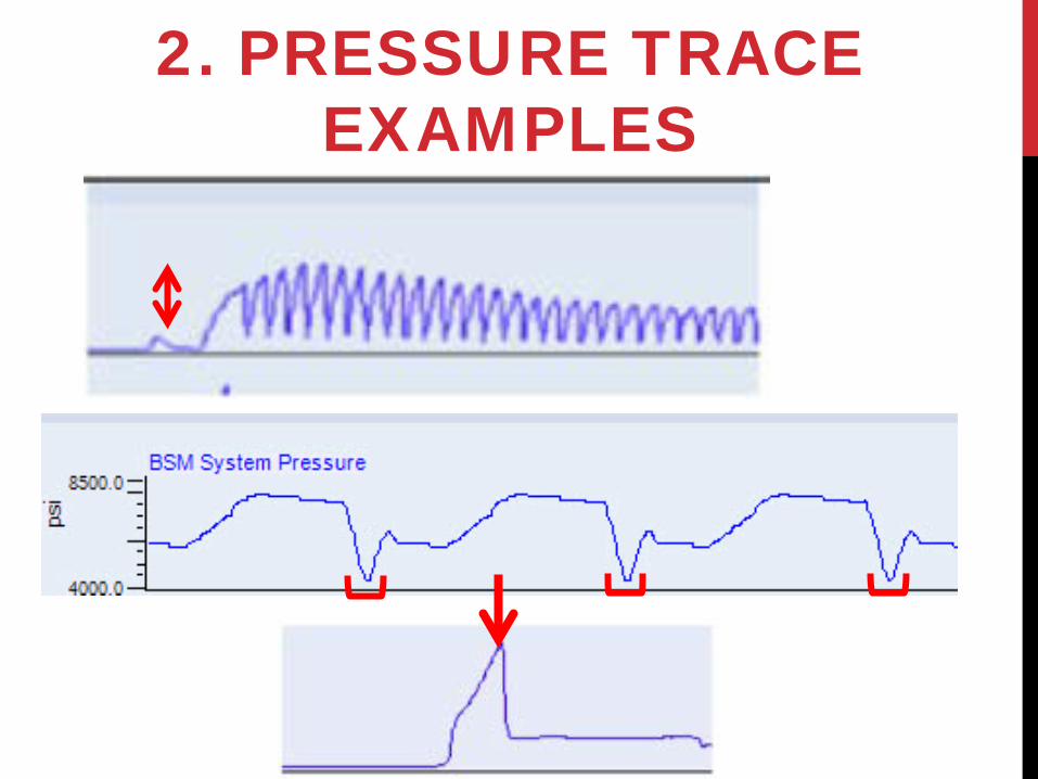
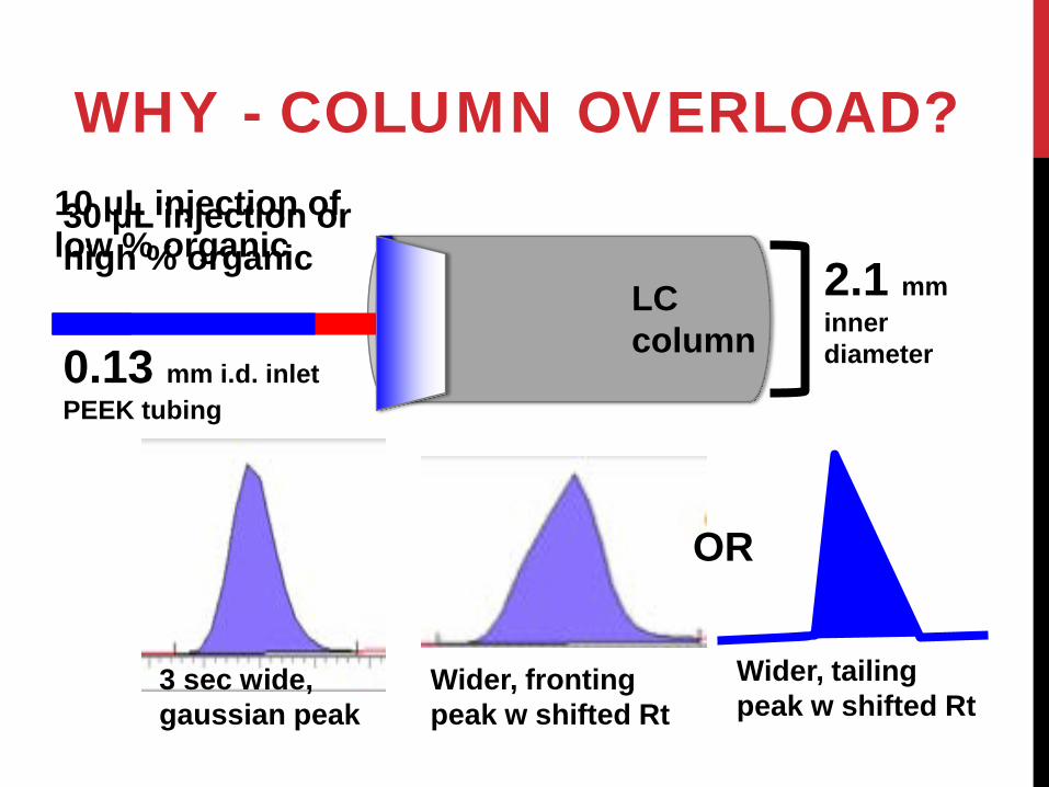
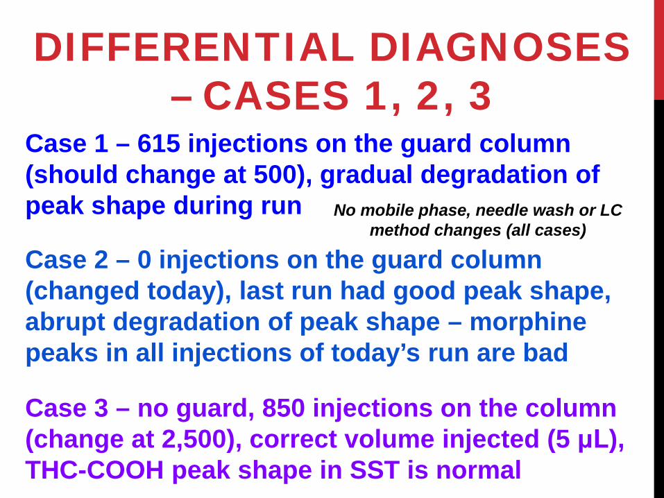
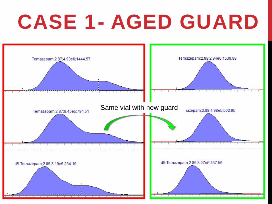

appearance of THC-COOH LLOQ calibrator
Quantifier MRM
Qualifier MRM
Internal Standard
MRM
Abnormal appearance of todayrsquos THC-COOH LLOQ calibrator
one two three four five
LOW SN ndash CASE 1
LOW SN ndash CASE 2
Why does the Fixed Y scale matter
TIC w Fixed Y scale ndash 14 e8 12
Todayrsquos High Benzodiazepine calibrator
TIC w Fixed Y scale ndash 14 e8
100
Yesterdayrsquos High Benzodiazepine calibrator
LOW SN ndash CASE 3
POLLING QUESTION 5
Without no additional information ndash can we
conclude that these 3 low SN cases are all MSMS related
(MSMS is source of the problem)
MSMS
Q3 collision Q1 cell
ALS
HOW TO PROCEED Pump ndash Sample Prep ndash Autosampler ndash Column ndash Divert Valve ndash MSMS (Tubing amp Connections) (Unauthorized method edits)
Pumps
Column Oven
Divert Valve
Waste
X X
X X
WHAT WOULD CAUSE LOW PEAK AREAS W NORMAL RTS NORMAL PEAK SHAPES
1 Sample preparation error
2 Too little volume injected from autosampler a Programming error b Autosampler problem (leak partially
plugged needle or needle seal ran out of needle wash)
3 Post-column leak (why only post column)
4 MSMS needs cleaning or calibration or source component replacement or detector voltage too low or MP contaminant = ion suppression
Wrong method ndash unauthorized method edit
HOW TO FIND THE SOURCE OF LOW PEAK AREAS WITH NORMAL
CHROMATOGRAPHY 1 Look at SST results today amp previous days 2 Inject stable extract from previous batch 3 Autosampler problem
a Check vials amp volume injected check that vialplate caps were pierced
b Inject extracts from other assays with similar injection volume
4 Look for post-column leak check LC pressure 5 Check MSMS signal calibration Rs - infusion
6 Check for method edits 7 Check for solvent lot
change
LOW SN CASE 1 1 No SST done for THC-COOH but Vit D
SST passed (so is the LC-MSMS OK) 2 Autosampler OK Inject THC-COOH
LLOQ calibrator from previous batch ndash normal (autosampler [LC] amp MSMS OK)
3 No leak from column to MSMS found normal starting pressure amp pressure trace
4 Ask the analyst who extracted the batch ndash anything abnormal happen
Instrument looks OK ndash problem with Sample Prep
POLLING QUESTION 6
If I tell you that the extraction method for this THC-COOH
case is solid phase extraction (SPE) ndash can you guess what
error is most likely
ldquoNOTHING WENT WRONG WITH THE EXTRACTION rdquo
OK - Inject several vials from problem batch on another instrument ndash same low peak areas
ldquoAre you absolutely sure there was nothing abnormal during extractionrdquo
ldquoOh except - forgot to substitute vials in place of waste bin from under SPE cartridges before adding elution solvent -- but I stopped flow and switched to vials immediatelyhelliphelliprdquo SOLUTION
LOW SN CASE 1
The majority of the analyte is often eluted in the first 10-20 of the elution solvent volume If the first 100 microL of the 1 mL of elution solvent goes to waste ndash expect VERY low recovery
Add Elution Solvent
Waste Bin
Error in SPE workflow CORRECT SPE workflow
appearance of THC-COOH LLOQ calibrator
Quantifier MRM
Qualifier MRM
Internal Standard
MRM
Abnormal appearance of todayrsquos THC-COOH LLOQ calibrator
Sample Prep Error (SPE eluate to waste) ndash
re-extract the batch
LOW SN CASE 2 1 SST passed 2 Autosampler OK Inject Benzodiazepine
calibrator from previous batch ndash same low peak areas
3 Obvious leak found at post-column switching valve in column oven
4 Why did SST pass with a leak present SST Threshold for acceptable peak area was set too low
5 Why is chromatography normal Separation occurred normally on the column leak is post column post separation
SOLUTION
LOW SN ndash CASE 2
TIC w Fixed Y scale ndash 14 e8 12
Todayrsquos High Benzodiazepine calibrator
TIC w Fixed Y scale ndash 14 e8
100
Yesterdayrsquos High Benzodiazepine calibrator
Post-column leak ndash
Fix the leak and re-
inject the batch
LOW SN CASE 3 1 SST borderline peak areas are low
barely acceptable Yesterdayrsquos calibrator injected today ndash also low
2 No extraction reagent or solvent lot changes no sample setup error was identified
3 ALS - Inject opiate low calibrator = normal peak area (autosampler OK)
4 No leaks found 5 Review trend of SST results
MSMS problem
SST TRACKING ndash
MEAN D2 IS PEAK AREAS FOR LC-MSMS
1 LC-MSMS 2 (mirror image
of 1) has D2 IS mean peak areas consistently
~90000 cps
Todayrsquos samples from 1 are injected on 2 -- D2 IS peak areas are ~ 85000 cps
on 2
What could be wrong with the 1 MSMS
WHAT MSMS PROBLEMS WOULD CAUSE LOW PEAK AREAS
1 Aged ESI capillary (replace it)
2 Mass Calibration andor Mass Resolution drifted (check it)
3 Detector voltage too low (test it)
4 MSMS interface is dirty (clean it)
POLLING QUESTION 7 Is a key operator (or anyall users) in your lab trained to perform anyall of the MSMS maintenance described 1 ESI capillary replacementprobe rebuild
andOR 2 VerifyPerform Mass Resolution amp Mass
Calibration andOR 3 CheckOptimize detector voltage
andOR 4 CleanInstall MSMS interface (front-end)
ion guide components
WHY ESI CAPILLARY ESI capillary is exposed
to high voltage amp temperature acidic
mobile phases biological matrix residue from extracted samples
Degradation
Decreased ionization
Courtesy of Waters
WHY MASS CALIBRATION ndash MASS RESOLUTION
Q1 Mass Resolution amp Mass Calibration result table Target Mass (Da)
Found at (Da)
Mass Shift
(+- 01)
Pass Peak Width
(06-08)
Pass
5905 5904 -001 YES 072 YES 17513 17515 +002 YES 068 YES 50038 50037 -001 YES 076 YES 61646 61646 +0003 YES 069 YES 90667 90665 -002 YES 065 YES 125493 125495 +002 YES 068 YES
Q1 Mass Resolution amp Mass Calibration result table Target Mass (Da)
Found at (Da)
Mass Shift
(+- 01)
Pass Peak Width
(06-08)
Pass
5905 5803 -102 NO 054 NO 17513 17432 -081 NO 058 NO 50038 49976 -062 NO 057 NO 61646 61603 -043 NO 060 YES 90667 90647 -020 NO 063 YES 125493 125484 -009 YES 068 YES
POLLING QUESTION 8 With quadrupole mass analyzers higher mass resolution (narrower MS peak widths) = lower signal abundance True = YES False or donrsquot know = NO
WHY DETECTOR VOLTAGE bull The detector counts ions amp amplifies
signal bull Higher voltage ndash shorter detector lifetime bull As the detector ages ndash voltage needs to
be increased to achieve the same amplification
bull Perform the detector voltage optimization test to check and if necessary increase the voltage
Not a substitute for cleaning the interface increases noise as well as signal
Region under vacuum
WHY INTERFACE CLEANING
LOW SN ndash CASE 3 1 ESI capillary was changed last month
(less likely to be the problem)
2 MSMS calibration amp resolution checked with infusion - meets specifications
3 Detector voltage checked ndash no increase is indicated
4 Vented the MSMS and replaced interface components with clean spare hardware ndash pumped down for 24 hrs
LOW SN ndash CASE 3
With clean interface components
With clean interface components
RT SHIFT CASE
WHAT MIGHT CAUSE A PROGRESSIVELY SHORTER RT
bull Typically think leak = late Rt bull Failing A pump or leak before
mixer might = early Rt bull Check the pressure trace
OVER-PRESSURE HISTORY bull Rarely a problem until last few
weeks thenhellip bull Several Rt shifts per week on both
instruments for protein-crash 25-OH Vitamin D method sometimes associated with system shutdown for over-pressure
bull What changed
INVESTIGATION bull Protein crash in ALS vials
multi-mixer centrifuge bull Checked multi-mixer amp
centrifuge speeds ndash normal bull No extraction reagent
change or error found bull Checked ALS needle heights bull Raised needle 2 mm no
further overpressure
POLLING QUESTION 9 With the same column flow rate and column temperature ndash will a 5050 (volvol) H2OMethanol mobile phase yield a higher column backpressure than a 2080 (volvol) H2OAcetonitrile mobile phase True = YES False or donrsquot know = NO
THE APPROACH TO SUCCESSFUL
TROUBLESHOOTING 1 Know your instrument
2 Use troubleshooting tools
3 Set up a good production infrastructure (including robust preventative maintenance) ndash see Appendix
4 Divide and conquer (Sample Prep or LC or MSMS)
LAST POLLING QUESTION
Do you want to see more troubleshooting cases
presentations like these
EMAIL ADDRESS JASTONEUCSDEDU
APPENDIX
1A KNOW YOUR INSTRUMENT - LC
1 Flow path details (between amp within components)
2 Cutting PEEK tubing connecting PEEK and stainless steel fittings correctly
3 Autosampler injection modes
4 Basic LC maintenance ndash changing [plunger seals check valves] [needle needle seal rotor seal stator sample loop]
1B KNOW YOUR INSTRUMENT - MSMS
5 MSMS Source cleaning normal appearance parts replacement (capillary ESI amp APCI probes corona discharge needle heaters)
6 MSMS Interface cleaning
7 MSMS detector voltage optimization
8 Roughing pumps ndash oil ballasting
9 Spare parts amp Tools inventory (LC amp MSMS)
1C KNOW YOUR INSTRUMENT - IT
10Project Directory amp File structure (extensions)
11How to find acquisition data file information
12How to edit LC amp MSMS acquisition and data analysis methods divert valve programs apply MS Rs amp Cal
13Basics of PC maintenance amp security
2 KNOW TROUBLE- SHOOTING TOOLS
1 Inspect LC baselines
2 Review LC pressure traces
3 Create XIC overlays (compare Peak Shapes amp Rt shifts between runs)
4 Carryover checks (L1-L2-H-H-L3-L4-L5)
5 Find leaks amp source of over-pressure (visual inspection pressure testing LC segments)
LC PEAK SHAPEndash WHAT CAN IT TELL YOU
BASELINE SIGNAL AND PRESSURE TRACES ndash WHAT
CAN THEY TELL YOU
3A SET UP A PRODUCTION INFRASTRUCTURE
1 Good compliance with robust maintenance charts ndash train everyone on how to make good LC connections
2 Reliable tracking for amp interpretation of SSTs
3 Set action limits for baseline Rt LC Pressure amp MSMS response (peak area) changes acceptable peak areas amp concentrations in blanks maximum batch sizes
4 Injection tracking for filters guard columns columns ndash set maximums
3B SET UP A PRODUCTION INFRASTRUCTURE
5 Use batch review sheets
6 Avoid mobile phase amp autosampler wash contaminants (LC-MS grade solvents amp water) maintain clean LC reagent containers
7 Keep spare clean MSMS interface components
8 Lot to lot tracking of EVERYTHING (including columns amp solvents)
4 DIVIDE amp CONQUER
4 SAMPLE PREP OR LC OR MSMS
A SST ndash Sample prep versus Instrument B MSMS infusion ndash LC vs MSMS C False alarm ndash maintenance chart review (silly human error suggests an instrument problem when in fact - all is well Did someone touch the instrument change a fluid make an edit)
LC PROBLEMS (MORE COMMON THAN MSMS OR SAMPLE PREP) A Leaks amp over-pressure can be detected using
bull Pressure traces pressure monitoring Rt changes bull Look at touch every connection for leaks with flow on amp
max pressure normally seen for the method in question bull Isolate segments of the LC amp check pressures (know what
flow rate AB to use expected segment pressures)
B Failing column guard filter plumbing connec-tions (extra-column dead volume) will appear as
bull Rt changes increased column guard filter pressure bull Peak shape peak area (early gt late eluters) changes - review
amp compare with previous good batches bull Loss of resolution between peaks carryover bull Usually related to use residual matrix ndash track of
injections
INJECTION MATRIX ldquoRULESrdquo (REVERSE PHASE) 1 Isocratic separation ndash
injection matrix organic solvent le 90 of mobile phase organic solvent
2 Gradient separation ndash determine experimentally more tolerant of higher organic amp larger injection volume (affected by column analyte mobile phase starting gradient conditions injection matrix injection volume)
Russ Grant rule ndash take the MSACL short course
LC COMPONENT WEAR - 1 1 Pump normal wear amp tear
bullRt shifts leaks pressure trace changes pressure monitoring changes
1st - prime mobile phases thoroughly (remove any air in the pump head) 2nd ndash Is correctuncontaminated mobile phase amp needle wash in the reservoirs 3rd - Check valve replacement cleaning 4th - Plunger seal replacement
LC COMPONENT WEAR - 2 2 Autosampler problems
bull No peaks decreased peak areas peak shape distortion carryover over-pressure from particulate in samples leaks LC plumbingconnection errors
bull Check for correctuncontaminated needle wash solutions
bull Prime needle wash solutions ndash no air in the linesvalves bull Over-pressure leak investigation bull Replace
bull Needle bull Needle seal bull Sample loop bull Rotor seal
MSMS INVESTIGATION 1 Infusion ndash verify mass resolution and mass calibration 2 Infusion ndash can be misleading signal is decreased but
infusion meets specifications (ionization differences at infusion rates vs LC flow rates and with B are VERY important)
3 Rely on good SST tracking ndash then RO the LC
1 With low signal ndash first -- what can be done wo venting a Silly human error (source not connected or flow not
directed to MSMS) b Rule out LC sample prep c Rule out mobile phase contaminants d Detector voltage check mass resolution amp calibration
check e Source capillary change needed f Interface cleaning needed
SAMPLE PREP INVESTIGATION SST ndash be sure review is detailed action limits are robust
SST rules out the instrument - then
1 Inject a sample from a previous good run 2 Inject the suspect samplebatch on another
instrument 3 Look at the vialplate caps look at the contents 4 Was there a lot change ndash IS calibrator
reagent 5 Review protocol steps with the analyst 6 Missed IS addition double IS addition 7 Mixing labeling pipetting variance ndash transfer
errors
COMMON SAMPLE PREP ERRORS
- The Basics of LC-MSMS Troubleshooting Tools cases strategy
- Thanks to
- OUtline
- Troubleshooting (diagnostic) tools
- Slide Number 5
- 1 Chromatographic images
- 1 Peak review examples
- 1TIC or XIC overlay
- 1 XIC overlay example
- 1 Advantages of using xic overlays
- Slide Number 11
- 2 LC pressure traces
- 2 Pressure trace examples
- Slide Number 14
- 3 Sst
- 3 Maintenance calendar
- Polling question 1
- 4 Acquisition data files
- Slide Number 19
- 5 Divide amp conquer
- 5 LC Divide amp conquer
- Cases
- Peak shape case 1
- Peak shape case 2
- Polling question 2
- Peak shape case 3
- What would cause abnormal peak shapes (all samples)
- Why - Frit or column aging
- Why ndash poor connections
- Why ndash poor connections
- Slide Number 31
- Making a good LC connection requires training
- Polling question 3
- Why - column overload
- Troubleshooting tools
- Differential diagnoses ndash cases 1 2 3
- case 1- aged guard
- Case 2ndashbad LC connection
- case 3 ndash wrong injection matrix (column overload)
- Polling question 4
- Low SN cases
- Slide Number 42
- Low SN ndash case 2
- Low SN ndash case 3
- Polling question 5
- How to proceed
- What would cause low peak areas w normal Rts normal peak shapes
- How to find the source of low peak areas with normal chromatography
- Low sN Case 1
- Polling question 6
- ldquoNothing went wrong with the extraction rdquo
- Low Sn Case 1
- Slide Number 53
- Low sN Case 2
- Low SN ndash case 2
- Low sN Case 3
- SST TRACKINGndash MEAN D2 ISpeak areas For LC-MSMS 1
- What MSMS problems would cause low peak areas
- POLLING QUESTION 7
- Why esi capillary
- Why mass calibration ndash mass resolution
- Polling question 8
- Why detector voltage
- Why interface cleaning
- Slide Number 65
- Low sN ndash case 3
- Low SN ndash case 3
- Rt shift case
- What might cause a progressively shorter Rt
- Over-pressure History
- Investigation
- Polling question 9
- The approach to successful troubleshooting
- Last polling question
- Email address jastoneucsdedu
- appendix
- 1a Know your instrument - LC
- 1b Know your instrument - MSMS
- 1c Know your instrument - IT
- 2 Know trouble- shooting tools
- LC Peak shapendash what can it tell you
- Baseline signal and pressure traces ndash what can they tell you
- 3a Set up a production infrastructure
- 3b Set up a production infrastructure
- 4 Divide amp Conquer
- 4 Sample prep or Lc or MSMS
- LC problems (more common than MSMS or Sample prep)
- Injection matrix ldquorulesrdquo (reverse phase)
- LC Component wear - 1
- LC Component wear - 2
- MSMS investigation
- Sample prep investigation
- Common sample prep errors
-

LOW SN ndash CASE 2
Why does the Fixed Y scale matter
TIC w Fixed Y scale ndash 14 e8 12
Todayrsquos High Benzodiazepine calibrator
TIC w Fixed Y scale ndash 14 e8
100
Yesterdayrsquos High Benzodiazepine calibrator
LOW SN ndash CASE 3
POLLING QUESTION 5
Without no additional information ndash can we
conclude that these 3 low SN cases are all MSMS related
(MSMS is source of the problem)
MSMS
Q3 collision Q1 cell
ALS
HOW TO PROCEED Pump ndash Sample Prep ndash Autosampler ndash Column ndash Divert Valve ndash MSMS (Tubing amp Connections) (Unauthorized method edits)
Pumps
Column Oven
Divert Valve
Waste
X X
X X
WHAT WOULD CAUSE LOW PEAK AREAS W NORMAL RTS NORMAL PEAK SHAPES
1 Sample preparation error
2 Too little volume injected from autosampler a Programming error b Autosampler problem (leak partially
plugged needle or needle seal ran out of needle wash)
3 Post-column leak (why only post column)
4 MSMS needs cleaning or calibration or source component replacement or detector voltage too low or MP contaminant = ion suppression
Wrong method ndash unauthorized method edit
HOW TO FIND THE SOURCE OF LOW PEAK AREAS WITH NORMAL
CHROMATOGRAPHY 1 Look at SST results today amp previous days 2 Inject stable extract from previous batch 3 Autosampler problem
a Check vials amp volume injected check that vialplate caps were pierced
b Inject extracts from other assays with similar injection volume
4 Look for post-column leak check LC pressure 5 Check MSMS signal calibration Rs - infusion
6 Check for method edits 7 Check for solvent lot
change
LOW SN CASE 1 1 No SST done for THC-COOH but Vit D
SST passed (so is the LC-MSMS OK) 2 Autosampler OK Inject THC-COOH
LLOQ calibrator from previous batch ndash normal (autosampler [LC] amp MSMS OK)
3 No leak from column to MSMS found normal starting pressure amp pressure trace
4 Ask the analyst who extracted the batch ndash anything abnormal happen
Instrument looks OK ndash problem with Sample Prep
POLLING QUESTION 6
If I tell you that the extraction method for this THC-COOH
case is solid phase extraction (SPE) ndash can you guess what
error is most likely
ldquoNOTHING WENT WRONG WITH THE EXTRACTION rdquo
OK - Inject several vials from problem batch on another instrument ndash same low peak areas
ldquoAre you absolutely sure there was nothing abnormal during extractionrdquo
ldquoOh except - forgot to substitute vials in place of waste bin from under SPE cartridges before adding elution solvent -- but I stopped flow and switched to vials immediatelyhelliphelliprdquo SOLUTION
LOW SN CASE 1
The majority of the analyte is often eluted in the first 10-20 of the elution solvent volume If the first 100 microL of the 1 mL of elution solvent goes to waste ndash expect VERY low recovery
Add Elution Solvent
Waste Bin
Error in SPE workflow CORRECT SPE workflow
appearance of THC-COOH LLOQ calibrator
Quantifier MRM
Qualifier MRM
Internal Standard
MRM
Abnormal appearance of todayrsquos THC-COOH LLOQ calibrator
Sample Prep Error (SPE eluate to waste) ndash
re-extract the batch
LOW SN CASE 2 1 SST passed 2 Autosampler OK Inject Benzodiazepine
calibrator from previous batch ndash same low peak areas
3 Obvious leak found at post-column switching valve in column oven
4 Why did SST pass with a leak present SST Threshold for acceptable peak area was set too low
5 Why is chromatography normal Separation occurred normally on the column leak is post column post separation
SOLUTION
LOW SN ndash CASE 2
TIC w Fixed Y scale ndash 14 e8 12
Todayrsquos High Benzodiazepine calibrator
TIC w Fixed Y scale ndash 14 e8
100
Yesterdayrsquos High Benzodiazepine calibrator
Post-column leak ndash
Fix the leak and re-
inject the batch
LOW SN CASE 3 1 SST borderline peak areas are low
barely acceptable Yesterdayrsquos calibrator injected today ndash also low
2 No extraction reagent or solvent lot changes no sample setup error was identified
3 ALS - Inject opiate low calibrator = normal peak area (autosampler OK)
4 No leaks found 5 Review trend of SST results
MSMS problem
SST TRACKING ndash
MEAN D2 IS PEAK AREAS FOR LC-MSMS
1 LC-MSMS 2 (mirror image
of 1) has D2 IS mean peak areas consistently
~90000 cps
Todayrsquos samples from 1 are injected on 2 -- D2 IS peak areas are ~ 85000 cps
on 2
What could be wrong with the 1 MSMS
WHAT MSMS PROBLEMS WOULD CAUSE LOW PEAK AREAS
1 Aged ESI capillary (replace it)
2 Mass Calibration andor Mass Resolution drifted (check it)
3 Detector voltage too low (test it)
4 MSMS interface is dirty (clean it)
POLLING QUESTION 7 Is a key operator (or anyall users) in your lab trained to perform anyall of the MSMS maintenance described 1 ESI capillary replacementprobe rebuild
andOR 2 VerifyPerform Mass Resolution amp Mass
Calibration andOR 3 CheckOptimize detector voltage
andOR 4 CleanInstall MSMS interface (front-end)
ion guide components
WHY ESI CAPILLARY ESI capillary is exposed
to high voltage amp temperature acidic
mobile phases biological matrix residue from extracted samples
Degradation
Decreased ionization
Courtesy of Waters
WHY MASS CALIBRATION ndash MASS RESOLUTION
Q1 Mass Resolution amp Mass Calibration result table Target Mass (Da)
Found at (Da)
Mass Shift
(+- 01)
Pass Peak Width
(06-08)
Pass
5905 5904 -001 YES 072 YES 17513 17515 +002 YES 068 YES 50038 50037 -001 YES 076 YES 61646 61646 +0003 YES 069 YES 90667 90665 -002 YES 065 YES 125493 125495 +002 YES 068 YES
Q1 Mass Resolution amp Mass Calibration result table Target Mass (Da)
Found at (Da)
Mass Shift
(+- 01)
Pass Peak Width
(06-08)
Pass
5905 5803 -102 NO 054 NO 17513 17432 -081 NO 058 NO 50038 49976 -062 NO 057 NO 61646 61603 -043 NO 060 YES 90667 90647 -020 NO 063 YES 125493 125484 -009 YES 068 YES
POLLING QUESTION 8 With quadrupole mass analyzers higher mass resolution (narrower MS peak widths) = lower signal abundance True = YES False or donrsquot know = NO
WHY DETECTOR VOLTAGE bull The detector counts ions amp amplifies
signal bull Higher voltage ndash shorter detector lifetime bull As the detector ages ndash voltage needs to
be increased to achieve the same amplification
bull Perform the detector voltage optimization test to check and if necessary increase the voltage
Not a substitute for cleaning the interface increases noise as well as signal
Region under vacuum
WHY INTERFACE CLEANING
LOW SN ndash CASE 3 1 ESI capillary was changed last month
(less likely to be the problem)
2 MSMS calibration amp resolution checked with infusion - meets specifications
3 Detector voltage checked ndash no increase is indicated
4 Vented the MSMS and replaced interface components with clean spare hardware ndash pumped down for 24 hrs
LOW SN ndash CASE 3
With clean interface components
With clean interface components
RT SHIFT CASE
WHAT MIGHT CAUSE A PROGRESSIVELY SHORTER RT
bull Typically think leak = late Rt bull Failing A pump or leak before
mixer might = early Rt bull Check the pressure trace
OVER-PRESSURE HISTORY bull Rarely a problem until last few
weeks thenhellip bull Several Rt shifts per week on both
instruments for protein-crash 25-OH Vitamin D method sometimes associated with system shutdown for over-pressure
bull What changed
INVESTIGATION bull Protein crash in ALS vials
multi-mixer centrifuge bull Checked multi-mixer amp
centrifuge speeds ndash normal bull No extraction reagent
change or error found bull Checked ALS needle heights bull Raised needle 2 mm no
further overpressure
POLLING QUESTION 9 With the same column flow rate and column temperature ndash will a 5050 (volvol) H2OMethanol mobile phase yield a higher column backpressure than a 2080 (volvol) H2OAcetonitrile mobile phase True = YES False or donrsquot know = NO
THE APPROACH TO SUCCESSFUL
TROUBLESHOOTING 1 Know your instrument
2 Use troubleshooting tools
3 Set up a good production infrastructure (including robust preventative maintenance) ndash see Appendix
4 Divide and conquer (Sample Prep or LC or MSMS)
LAST POLLING QUESTION
Do you want to see more troubleshooting cases
presentations like these
EMAIL ADDRESS JASTONEUCSDEDU
APPENDIX
1A KNOW YOUR INSTRUMENT - LC
1 Flow path details (between amp within components)
2 Cutting PEEK tubing connecting PEEK and stainless steel fittings correctly
3 Autosampler injection modes
4 Basic LC maintenance ndash changing [plunger seals check valves] [needle needle seal rotor seal stator sample loop]
1B KNOW YOUR INSTRUMENT - MSMS
5 MSMS Source cleaning normal appearance parts replacement (capillary ESI amp APCI probes corona discharge needle heaters)
6 MSMS Interface cleaning
7 MSMS detector voltage optimization
8 Roughing pumps ndash oil ballasting
9 Spare parts amp Tools inventory (LC amp MSMS)
1C KNOW YOUR INSTRUMENT - IT
10Project Directory amp File structure (extensions)
11How to find acquisition data file information
12How to edit LC amp MSMS acquisition and data analysis methods divert valve programs apply MS Rs amp Cal
13Basics of PC maintenance amp security
2 KNOW TROUBLE- SHOOTING TOOLS
1 Inspect LC baselines
2 Review LC pressure traces
3 Create XIC overlays (compare Peak Shapes amp Rt shifts between runs)
4 Carryover checks (L1-L2-H-H-L3-L4-L5)
5 Find leaks amp source of over-pressure (visual inspection pressure testing LC segments)
LC PEAK SHAPEndash WHAT CAN IT TELL YOU
BASELINE SIGNAL AND PRESSURE TRACES ndash WHAT
CAN THEY TELL YOU
3A SET UP A PRODUCTION INFRASTRUCTURE
1 Good compliance with robust maintenance charts ndash train everyone on how to make good LC connections
2 Reliable tracking for amp interpretation of SSTs
3 Set action limits for baseline Rt LC Pressure amp MSMS response (peak area) changes acceptable peak areas amp concentrations in blanks maximum batch sizes
4 Injection tracking for filters guard columns columns ndash set maximums
3B SET UP A PRODUCTION INFRASTRUCTURE
5 Use batch review sheets
6 Avoid mobile phase amp autosampler wash contaminants (LC-MS grade solvents amp water) maintain clean LC reagent containers
7 Keep spare clean MSMS interface components
8 Lot to lot tracking of EVERYTHING (including columns amp solvents)
4 DIVIDE amp CONQUER
4 SAMPLE PREP OR LC OR MSMS
A SST ndash Sample prep versus Instrument B MSMS infusion ndash LC vs MSMS C False alarm ndash maintenance chart review (silly human error suggests an instrument problem when in fact - all is well Did someone touch the instrument change a fluid make an edit)
LC PROBLEMS (MORE COMMON THAN MSMS OR SAMPLE PREP) A Leaks amp over-pressure can be detected using
bull Pressure traces pressure monitoring Rt changes bull Look at touch every connection for leaks with flow on amp
max pressure normally seen for the method in question bull Isolate segments of the LC amp check pressures (know what
flow rate AB to use expected segment pressures)
B Failing column guard filter plumbing connec-tions (extra-column dead volume) will appear as
bull Rt changes increased column guard filter pressure bull Peak shape peak area (early gt late eluters) changes - review
amp compare with previous good batches bull Loss of resolution between peaks carryover bull Usually related to use residual matrix ndash track of
injections
INJECTION MATRIX ldquoRULESrdquo (REVERSE PHASE) 1 Isocratic separation ndash
injection matrix organic solvent le 90 of mobile phase organic solvent
2 Gradient separation ndash determine experimentally more tolerant of higher organic amp larger injection volume (affected by column analyte mobile phase starting gradient conditions injection matrix injection volume)
Russ Grant rule ndash take the MSACL short course
LC COMPONENT WEAR - 1 1 Pump normal wear amp tear
bullRt shifts leaks pressure trace changes pressure monitoring changes
1st - prime mobile phases thoroughly (remove any air in the pump head) 2nd ndash Is correctuncontaminated mobile phase amp needle wash in the reservoirs 3rd - Check valve replacement cleaning 4th - Plunger seal replacement
LC COMPONENT WEAR - 2 2 Autosampler problems
bull No peaks decreased peak areas peak shape distortion carryover over-pressure from particulate in samples leaks LC plumbingconnection errors
bull Check for correctuncontaminated needle wash solutions
bull Prime needle wash solutions ndash no air in the linesvalves bull Over-pressure leak investigation bull Replace
bull Needle bull Needle seal bull Sample loop bull Rotor seal
MSMS INVESTIGATION 1 Infusion ndash verify mass resolution and mass calibration 2 Infusion ndash can be misleading signal is decreased but
infusion meets specifications (ionization differences at infusion rates vs LC flow rates and with B are VERY important)
3 Rely on good SST tracking ndash then RO the LC
1 With low signal ndash first -- what can be done wo venting a Silly human error (source not connected or flow not
directed to MSMS) b Rule out LC sample prep c Rule out mobile phase contaminants d Detector voltage check mass resolution amp calibration
check e Source capillary change needed f Interface cleaning needed
SAMPLE PREP INVESTIGATION SST ndash be sure review is detailed action limits are robust
SST rules out the instrument - then
1 Inject a sample from a previous good run 2 Inject the suspect samplebatch on another
instrument 3 Look at the vialplate caps look at the contents 4 Was there a lot change ndash IS calibrator
reagent 5 Review protocol steps with the analyst 6 Missed IS addition double IS addition 7 Mixing labeling pipetting variance ndash transfer
errors
COMMON SAMPLE PREP ERRORS
- The Basics of LC-MSMS Troubleshooting Tools cases strategy
- Thanks to
- OUtline
- Troubleshooting (diagnostic) tools
- Slide Number 5
- 1 Chromatographic images
- 1 Peak review examples
- 1TIC or XIC overlay
- 1 XIC overlay example
- 1 Advantages of using xic overlays
- Slide Number 11
- 2 LC pressure traces
- 2 Pressure trace examples
- Slide Number 14
- 3 Sst
- 3 Maintenance calendar
- Polling question 1
- 4 Acquisition data files
- Slide Number 19
- 5 Divide amp conquer
- 5 LC Divide amp conquer
- Cases
- Peak shape case 1
- Peak shape case 2
- Polling question 2
- Peak shape case 3
- What would cause abnormal peak shapes (all samples)
- Why - Frit or column aging
- Why ndash poor connections
- Why ndash poor connections
- Slide Number 31
- Making a good LC connection requires training
- Polling question 3
- Why - column overload
- Troubleshooting tools
- Differential diagnoses ndash cases 1 2 3
- case 1- aged guard
- Case 2ndashbad LC connection
- case 3 ndash wrong injection matrix (column overload)
- Polling question 4
- Low SN cases
- Slide Number 42
- Low SN ndash case 2
- Low SN ndash case 3
- Polling question 5
- How to proceed
- What would cause low peak areas w normal Rts normal peak shapes
- How to find the source of low peak areas with normal chromatography
- Low sN Case 1
- Polling question 6
- ldquoNothing went wrong with the extraction rdquo
- Low Sn Case 1
- Slide Number 53
- Low sN Case 2
- Low SN ndash case 2
- Low sN Case 3
- SST TRACKINGndash MEAN D2 ISpeak areas For LC-MSMS 1
- What MSMS problems would cause low peak areas
- POLLING QUESTION 7
- Why esi capillary
- Why mass calibration ndash mass resolution
- Polling question 8
- Why detector voltage
- Why interface cleaning
- Slide Number 65
- Low sN ndash case 3
- Low SN ndash case 3
- Rt shift case
- What might cause a progressively shorter Rt
- Over-pressure History
- Investigation
- Polling question 9
- The approach to successful troubleshooting
- Last polling question
- Email address jastoneucsdedu
- appendix
- 1a Know your instrument - LC
- 1b Know your instrument - MSMS
- 1c Know your instrument - IT
- 2 Know trouble- shooting tools
- LC Peak shapendash what can it tell you
- Baseline signal and pressure traces ndash what can they tell you
- 3a Set up a production infrastructure
- 3b Set up a production infrastructure
- 4 Divide amp Conquer
- 4 Sample prep or Lc or MSMS
- LC problems (more common than MSMS or Sample prep)
- Injection matrix ldquorulesrdquo (reverse phase)
- LC Component wear - 1
- LC Component wear - 2
- MSMS investigation
- Sample prep investigation
- Common sample prep errors
-

LOW SN ndash CASE 3
POLLING QUESTION 5
Without no additional information ndash can we
conclude that these 3 low SN cases are all MSMS related
(MSMS is source of the problem)
MSMS
Q3 collision Q1 cell
ALS
HOW TO PROCEED Pump ndash Sample Prep ndash Autosampler ndash Column ndash Divert Valve ndash MSMS (Tubing amp Connections) (Unauthorized method edits)
Pumps
Column Oven
Divert Valve
Waste
X X
X X
WHAT WOULD CAUSE LOW PEAK AREAS W NORMAL RTS NORMAL PEAK SHAPES
1 Sample preparation error
2 Too little volume injected from autosampler a Programming error b Autosampler problem (leak partially
plugged needle or needle seal ran out of needle wash)
3 Post-column leak (why only post column)
4 MSMS needs cleaning or calibration or source component replacement or detector voltage too low or MP contaminant = ion suppression
Wrong method ndash unauthorized method edit
HOW TO FIND THE SOURCE OF LOW PEAK AREAS WITH NORMAL
CHROMATOGRAPHY 1 Look at SST results today amp previous days 2 Inject stable extract from previous batch 3 Autosampler problem
a Check vials amp volume injected check that vialplate caps were pierced
b Inject extracts from other assays with similar injection volume
4 Look for post-column leak check LC pressure 5 Check MSMS signal calibration Rs - infusion
6 Check for method edits 7 Check for solvent lot
change
LOW SN CASE 1 1 No SST done for THC-COOH but Vit D
SST passed (so is the LC-MSMS OK) 2 Autosampler OK Inject THC-COOH
LLOQ calibrator from previous batch ndash normal (autosampler [LC] amp MSMS OK)
3 No leak from column to MSMS found normal starting pressure amp pressure trace
4 Ask the analyst who extracted the batch ndash anything abnormal happen
Instrument looks OK ndash problem with Sample Prep
POLLING QUESTION 6
If I tell you that the extraction method for this THC-COOH
case is solid phase extraction (SPE) ndash can you guess what
error is most likely
ldquoNOTHING WENT WRONG WITH THE EXTRACTION rdquo
OK - Inject several vials from problem batch on another instrument ndash same low peak areas
ldquoAre you absolutely sure there was nothing abnormal during extractionrdquo
ldquoOh except - forgot to substitute vials in place of waste bin from under SPE cartridges before adding elution solvent -- but I stopped flow and switched to vials immediatelyhelliphelliprdquo SOLUTION
LOW SN CASE 1
The majority of the analyte is often eluted in the first 10-20 of the elution solvent volume If the first 100 microL of the 1 mL of elution solvent goes to waste ndash expect VERY low recovery
Add Elution Solvent
Waste Bin
Error in SPE workflow CORRECT SPE workflow
appearance of THC-COOH LLOQ calibrator
Quantifier MRM
Qualifier MRM
Internal Standard
MRM
Abnormal appearance of todayrsquos THC-COOH LLOQ calibrator
Sample Prep Error (SPE eluate to waste) ndash
re-extract the batch
LOW SN CASE 2 1 SST passed 2 Autosampler OK Inject Benzodiazepine
calibrator from previous batch ndash same low peak areas
3 Obvious leak found at post-column switching valve in column oven
4 Why did SST pass with a leak present SST Threshold for acceptable peak area was set too low
5 Why is chromatography normal Separation occurred normally on the column leak is post column post separation
SOLUTION
LOW SN ndash CASE 2
TIC w Fixed Y scale ndash 14 e8 12
Todayrsquos High Benzodiazepine calibrator
TIC w Fixed Y scale ndash 14 e8
100
Yesterdayrsquos High Benzodiazepine calibrator
Post-column leak ndash
Fix the leak and re-
inject the batch
LOW SN CASE 3 1 SST borderline peak areas are low
barely acceptable Yesterdayrsquos calibrator injected today ndash also low
2 No extraction reagent or solvent lot changes no sample setup error was identified
3 ALS - Inject opiate low calibrator = normal peak area (autosampler OK)
4 No leaks found 5 Review trend of SST results
MSMS problem
SST TRACKING ndash
MEAN D2 IS PEAK AREAS FOR LC-MSMS
1 LC-MSMS 2 (mirror image
of 1) has D2 IS mean peak areas consistently
~90000 cps
Todayrsquos samples from 1 are injected on 2 -- D2 IS peak areas are ~ 85000 cps
on 2
What could be wrong with the 1 MSMS
WHAT MSMS PROBLEMS WOULD CAUSE LOW PEAK AREAS
1 Aged ESI capillary (replace it)
2 Mass Calibration andor Mass Resolution drifted (check it)
3 Detector voltage too low (test it)
4 MSMS interface is dirty (clean it)
POLLING QUESTION 7 Is a key operator (or anyall users) in your lab trained to perform anyall of the MSMS maintenance described 1 ESI capillary replacementprobe rebuild
andOR 2 VerifyPerform Mass Resolution amp Mass
Calibration andOR 3 CheckOptimize detector voltage
andOR 4 CleanInstall MSMS interface (front-end)
ion guide components
WHY ESI CAPILLARY ESI capillary is exposed
to high voltage amp temperature acidic
mobile phases biological matrix residue from extracted samples
Degradation
Decreased ionization
Courtesy of Waters
WHY MASS CALIBRATION ndash MASS RESOLUTION
Q1 Mass Resolution amp Mass Calibration result table Target Mass (Da)
Found at (Da)
Mass Shift
(+- 01)
Pass Peak Width
(06-08)
Pass
5905 5904 -001 YES 072 YES 17513 17515 +002 YES 068 YES 50038 50037 -001 YES 076 YES 61646 61646 +0003 YES 069 YES 90667 90665 -002 YES 065 YES 125493 125495 +002 YES 068 YES
Q1 Mass Resolution amp Mass Calibration result table Target Mass (Da)
Found at (Da)
Mass Shift
(+- 01)
Pass Peak Width
(06-08)
Pass
5905 5803 -102 NO 054 NO 17513 17432 -081 NO 058 NO 50038 49976 -062 NO 057 NO 61646 61603 -043 NO 060 YES 90667 90647 -020 NO 063 YES 125493 125484 -009 YES 068 YES
POLLING QUESTION 8 With quadrupole mass analyzers higher mass resolution (narrower MS peak widths) = lower signal abundance True = YES False or donrsquot know = NO
WHY DETECTOR VOLTAGE bull The detector counts ions amp amplifies
signal bull Higher voltage ndash shorter detector lifetime bull As the detector ages ndash voltage needs to
be increased to achieve the same amplification
bull Perform the detector voltage optimization test to check and if necessary increase the voltage
Not a substitute for cleaning the interface increases noise as well as signal
Region under vacuum
WHY INTERFACE CLEANING
LOW SN ndash CASE 3 1 ESI capillary was changed last month
(less likely to be the problem)
2 MSMS calibration amp resolution checked with infusion - meets specifications
3 Detector voltage checked ndash no increase is indicated
4 Vented the MSMS and replaced interface components with clean spare hardware ndash pumped down for 24 hrs
LOW SN ndash CASE 3
With clean interface components
With clean interface components
RT SHIFT CASE
WHAT MIGHT CAUSE A PROGRESSIVELY SHORTER RT
bull Typically think leak = late Rt bull Failing A pump or leak before
mixer might = early Rt bull Check the pressure trace
OVER-PRESSURE HISTORY bull Rarely a problem until last few
weeks thenhellip bull Several Rt shifts per week on both
instruments for protein-crash 25-OH Vitamin D method sometimes associated with system shutdown for over-pressure
bull What changed
INVESTIGATION bull Protein crash in ALS vials
multi-mixer centrifuge bull Checked multi-mixer amp
centrifuge speeds ndash normal bull No extraction reagent
change or error found bull Checked ALS needle heights bull Raised needle 2 mm no
further overpressure
POLLING QUESTION 9 With the same column flow rate and column temperature ndash will a 5050 (volvol) H2OMethanol mobile phase yield a higher column backpressure than a 2080 (volvol) H2OAcetonitrile mobile phase True = YES False or donrsquot know = NO
THE APPROACH TO SUCCESSFUL
TROUBLESHOOTING 1 Know your instrument
2 Use troubleshooting tools
3 Set up a good production infrastructure (including robust preventative maintenance) ndash see Appendix
4 Divide and conquer (Sample Prep or LC or MSMS)
LAST POLLING QUESTION
Do you want to see more troubleshooting cases
presentations like these
EMAIL ADDRESS JASTONEUCSDEDU
APPENDIX
1A KNOW YOUR INSTRUMENT - LC
1 Flow path details (between amp within components)
2 Cutting PEEK tubing connecting PEEK and stainless steel fittings correctly
3 Autosampler injection modes
4 Basic LC maintenance ndash changing [plunger seals check valves] [needle needle seal rotor seal stator sample loop]
1B KNOW YOUR INSTRUMENT - MSMS
5 MSMS Source cleaning normal appearance parts replacement (capillary ESI amp APCI probes corona discharge needle heaters)
6 MSMS Interface cleaning
7 MSMS detector voltage optimization
8 Roughing pumps ndash oil ballasting
9 Spare parts amp Tools inventory (LC amp MSMS)
1C KNOW YOUR INSTRUMENT - IT
10Project Directory amp File structure (extensions)
11How to find acquisition data file information
12How to edit LC amp MSMS acquisition and data analysis methods divert valve programs apply MS Rs amp Cal
13Basics of PC maintenance amp security
2 KNOW TROUBLE- SHOOTING TOOLS
1 Inspect LC baselines
2 Review LC pressure traces
3 Create XIC overlays (compare Peak Shapes amp Rt shifts between runs)
4 Carryover checks (L1-L2-H-H-L3-L4-L5)
5 Find leaks amp source of over-pressure (visual inspection pressure testing LC segments)
LC PEAK SHAPEndash WHAT CAN IT TELL YOU
BASELINE SIGNAL AND PRESSURE TRACES ndash WHAT
CAN THEY TELL YOU
3A SET UP A PRODUCTION INFRASTRUCTURE
1 Good compliance with robust maintenance charts ndash train everyone on how to make good LC connections
2 Reliable tracking for amp interpretation of SSTs
3 Set action limits for baseline Rt LC Pressure amp MSMS response (peak area) changes acceptable peak areas amp concentrations in blanks maximum batch sizes
4 Injection tracking for filters guard columns columns ndash set maximums
3B SET UP A PRODUCTION INFRASTRUCTURE
5 Use batch review sheets
6 Avoid mobile phase amp autosampler wash contaminants (LC-MS grade solvents amp water) maintain clean LC reagent containers
7 Keep spare clean MSMS interface components
8 Lot to lot tracking of EVERYTHING (including columns amp solvents)
4 DIVIDE amp CONQUER
4 SAMPLE PREP OR LC OR MSMS
A SST ndash Sample prep versus Instrument B MSMS infusion ndash LC vs MSMS C False alarm ndash maintenance chart review (silly human error suggests an instrument problem when in fact - all is well Did someone touch the instrument change a fluid make an edit)
LC PROBLEMS (MORE COMMON THAN MSMS OR SAMPLE PREP) A Leaks amp over-pressure can be detected using
bull Pressure traces pressure monitoring Rt changes bull Look at touch every connection for leaks with flow on amp
max pressure normally seen for the method in question bull Isolate segments of the LC amp check pressures (know what
flow rate AB to use expected segment pressures)
B Failing column guard filter plumbing connec-tions (extra-column dead volume) will appear as
bull Rt changes increased column guard filter pressure bull Peak shape peak area (early gt late eluters) changes - review
amp compare with previous good batches bull Loss of resolution between peaks carryover bull Usually related to use residual matrix ndash track of
injections
INJECTION MATRIX ldquoRULESrdquo (REVERSE PHASE) 1 Isocratic separation ndash
injection matrix organic solvent le 90 of mobile phase organic solvent
2 Gradient separation ndash determine experimentally more tolerant of higher organic amp larger injection volume (affected by column analyte mobile phase starting gradient conditions injection matrix injection volume)
Russ Grant rule ndash take the MSACL short course
LC COMPONENT WEAR - 1 1 Pump normal wear amp tear
bullRt shifts leaks pressure trace changes pressure monitoring changes
1st - prime mobile phases thoroughly (remove any air in the pump head) 2nd ndash Is correctuncontaminated mobile phase amp needle wash in the reservoirs 3rd - Check valve replacement cleaning 4th - Plunger seal replacement
LC COMPONENT WEAR - 2 2 Autosampler problems
bull No peaks decreased peak areas peak shape distortion carryover over-pressure from particulate in samples leaks LC plumbingconnection errors
bull Check for correctuncontaminated needle wash solutions
bull Prime needle wash solutions ndash no air in the linesvalves bull Over-pressure leak investigation bull Replace
bull Needle bull Needle seal bull Sample loop bull Rotor seal
MSMS INVESTIGATION 1 Infusion ndash verify mass resolution and mass calibration 2 Infusion ndash can be misleading signal is decreased but
infusion meets specifications (ionization differences at infusion rates vs LC flow rates and with B are VERY important)
3 Rely on good SST tracking ndash then RO the LC
1 With low signal ndash first -- what can be done wo venting a Silly human error (source not connected or flow not
directed to MSMS) b Rule out LC sample prep c Rule out mobile phase contaminants d Detector voltage check mass resolution amp calibration
check e Source capillary change needed f Interface cleaning needed
SAMPLE PREP INVESTIGATION SST ndash be sure review is detailed action limits are robust
SST rules out the instrument - then
1 Inject a sample from a previous good run 2 Inject the suspect samplebatch on another
instrument 3 Look at the vialplate caps look at the contents 4 Was there a lot change ndash IS calibrator
reagent 5 Review protocol steps with the analyst 6 Missed IS addition double IS addition 7 Mixing labeling pipetting variance ndash transfer
errors
COMMON SAMPLE PREP ERRORS
- The Basics of LC-MSMS Troubleshooting Tools cases strategy
- Thanks to
- OUtline
- Troubleshooting (diagnostic) tools
- Slide Number 5
- 1 Chromatographic images
- 1 Peak review examples
- 1TIC or XIC overlay
- 1 XIC overlay example
- 1 Advantages of using xic overlays
- Slide Number 11
- 2 LC pressure traces
- 2 Pressure trace examples
- Slide Number 14
- 3 Sst
- 3 Maintenance calendar
- Polling question 1
- 4 Acquisition data files
- Slide Number 19
- 5 Divide amp conquer
- 5 LC Divide amp conquer
- Cases
- Peak shape case 1
- Peak shape case 2
- Polling question 2
- Peak shape case 3
- What would cause abnormal peak shapes (all samples)
- Why - Frit or column aging
- Why ndash poor connections
- Why ndash poor connections
- Slide Number 31
- Making a good LC connection requires training
- Polling question 3
- Why - column overload
- Troubleshooting tools
- Differential diagnoses ndash cases 1 2 3
- case 1- aged guard
- Case 2ndashbad LC connection
- case 3 ndash wrong injection matrix (column overload)
- Polling question 4
- Low SN cases
- Slide Number 42
- Low SN ndash case 2
- Low SN ndash case 3
- Polling question 5
- How to proceed
- What would cause low peak areas w normal Rts normal peak shapes
- How to find the source of low peak areas with normal chromatography
- Low sN Case 1
- Polling question 6
- ldquoNothing went wrong with the extraction rdquo
- Low Sn Case 1
- Slide Number 53
- Low sN Case 2
- Low SN ndash case 2
- Low sN Case 3
- SST TRACKINGndash MEAN D2 ISpeak areas For LC-MSMS 1
- What MSMS problems would cause low peak areas
- POLLING QUESTION 7
- Why esi capillary
- Why mass calibration ndash mass resolution
- Polling question 8
- Why detector voltage
- Why interface cleaning
- Slide Number 65
- Low sN ndash case 3
- Low SN ndash case 3
- Rt shift case
- What might cause a progressively shorter Rt
- Over-pressure History
- Investigation
- Polling question 9
- The approach to successful troubleshooting
- Last polling question
- Email address jastoneucsdedu
- appendix
- 1a Know your instrument - LC
- 1b Know your instrument - MSMS
- 1c Know your instrument - IT
- 2 Know trouble- shooting tools
- LC Peak shapendash what can it tell you
- Baseline signal and pressure traces ndash what can they tell you
- 3a Set up a production infrastructure
- 3b Set up a production infrastructure
- 4 Divide amp Conquer
- 4 Sample prep or Lc or MSMS
- LC problems (more common than MSMS or Sample prep)
- Injection matrix ldquorulesrdquo (reverse phase)
- LC Component wear - 1
- LC Component wear - 2
- MSMS investigation
- Sample prep investigation
- Common sample prep errors
-
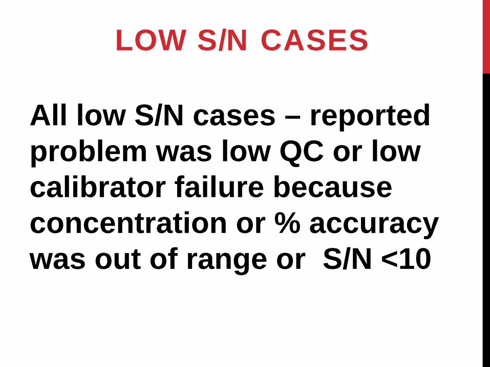
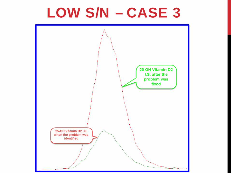
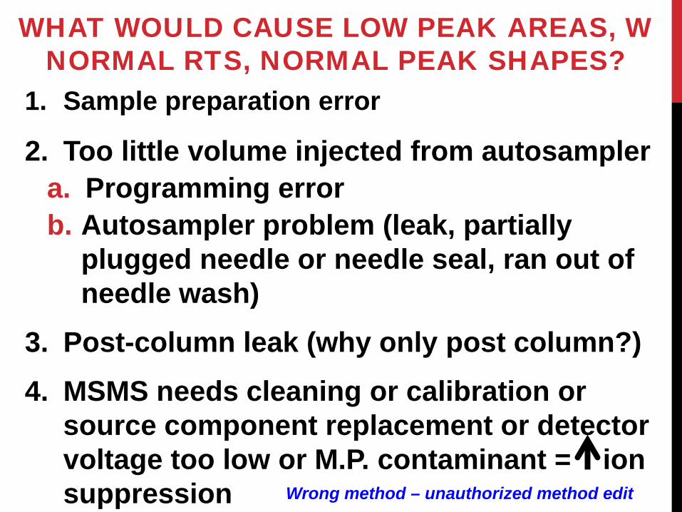
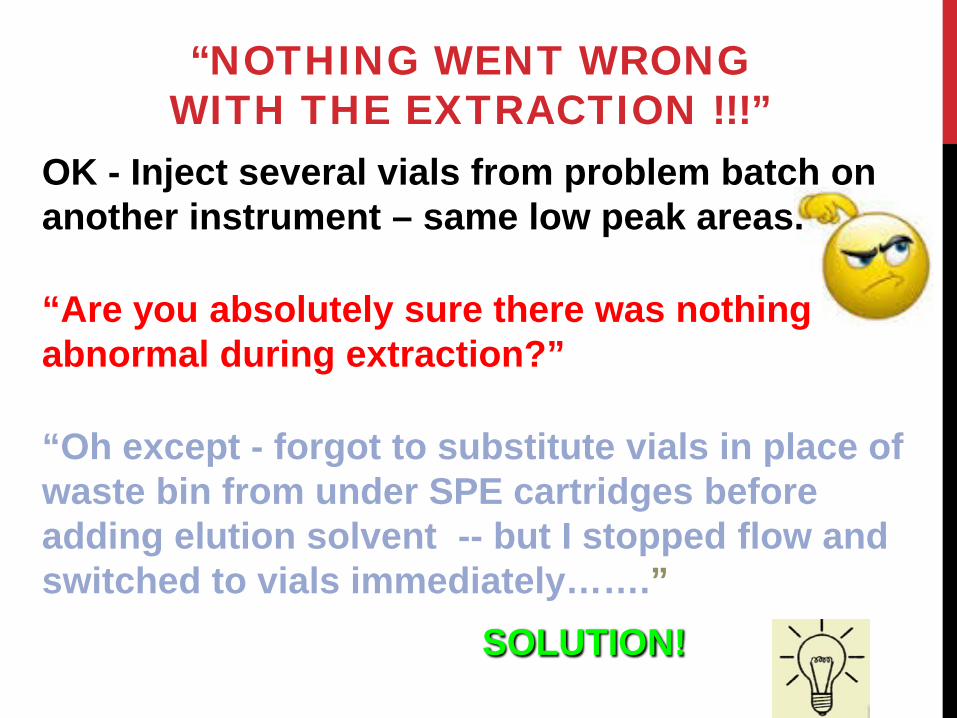
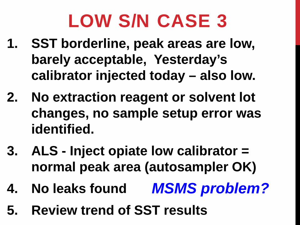
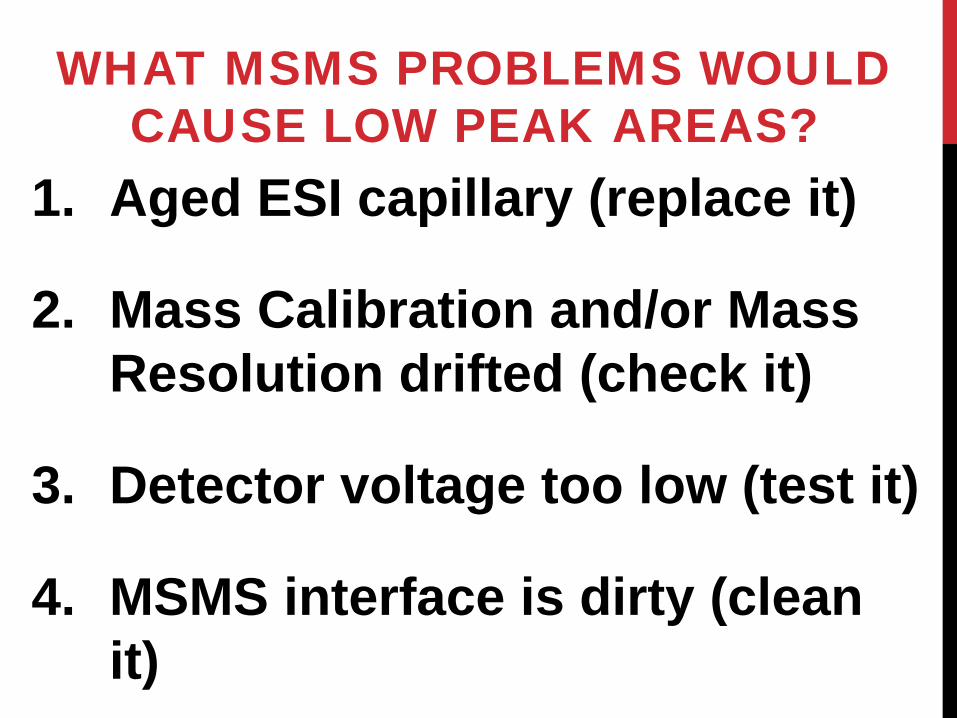
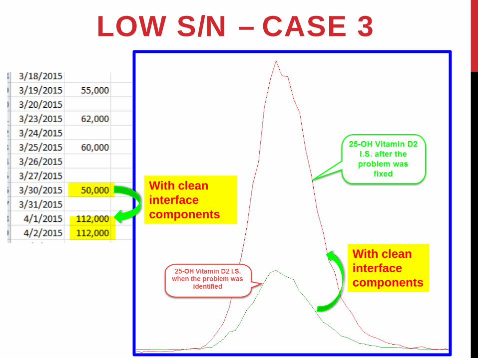
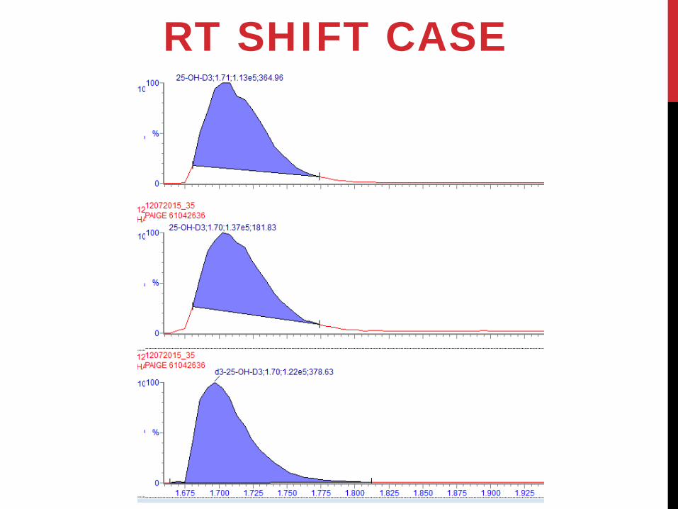
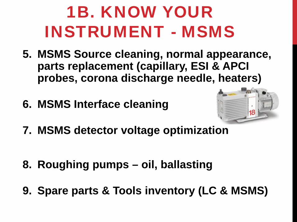
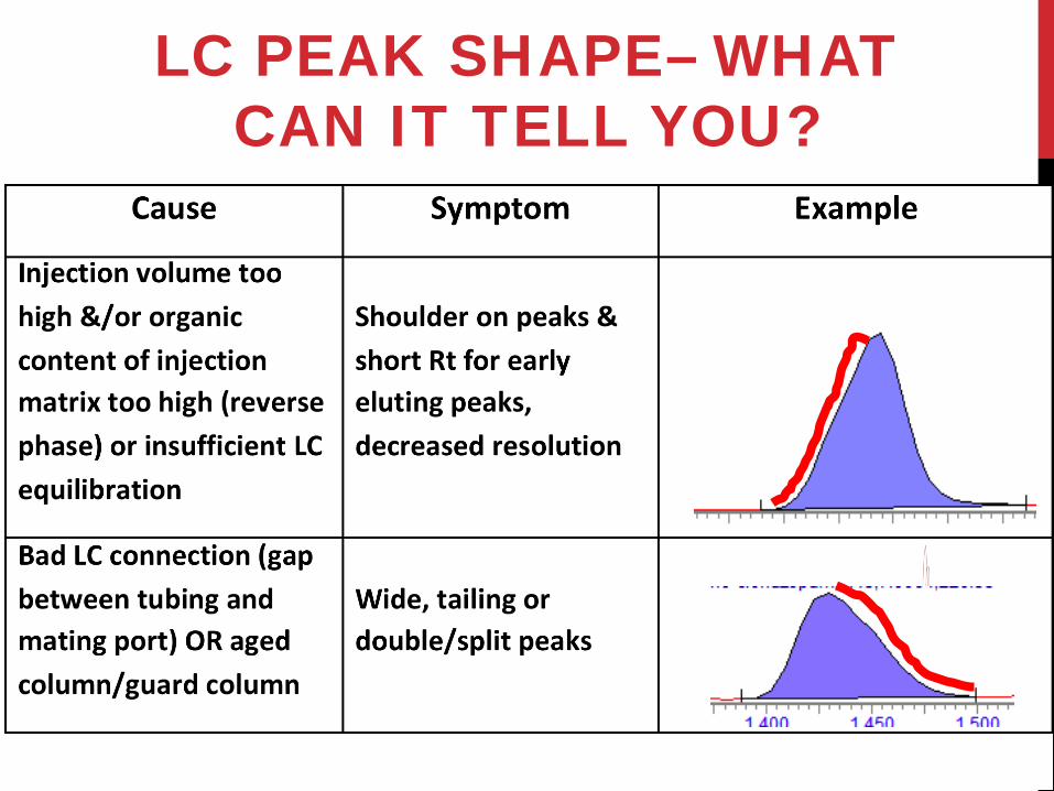