the bolts used for the connections of this steel framework ... · or points of contact between...
TRANSCRIPT

The bolts used for the connections of this steel framework are subjected to stress. Inthis chapter we will discuss how engineers design these connections and theirfasteners.
HEBBMC01_0132209918.QXD 7/14/07 11:49 AM Page 2
Stress
CHAPTER OBJECTIVES
In this chapter we will review some of the important principles of statics andshow how they are used to determine the internal resultant loadings in a body.Afterwards the concepts of normal and shear stress will be introduced, andspecific applications of the analysis and design of members subjected to anaxial load or direct shear will be discussed.
1.1 Introduction
Mechanics of materials is a branch of mechanics that studies therelationships between the external loads applied to a deformable bodyand the intensity of internal forces acting within the body. This subjectalso involves computing the deformations of the body, and it provides astudy of the body’s stability when the body is subjected to external forces.
In the design of any structure or machine, it is first necessary to use theprinciples of statics to determine the forces acting both on and within itsvarious members. The size of the members, their deflection, and theirstability depend not only on the internal loadings, but also on the type ofmaterial from which the members are made. Consequently, an accuratedetermination and fundamental understanding of material behavior willbe of vital importance for developing the necessary equations used inmechanics of materials. Realize that many formulas and rules for design,as defined in engineering codes and used in practice, are based on thefundamentals of mechanics of materials, and for this reason anunderstanding of the principles of this subject is very important.
3
1
HEBBMC01_0132209918.QXD 7/9/07 2:51 PM Page 3

4 CHAPTER 1 STRESS
Historical Development. The origin of mechanics of materialsdates back to the beginning of the seventeenth century, when Galileoperformed experiments to study the effects of loads on rods and beamsmade of various materials. For a proper understanding, however, it wasnecessary to establish accurate experimental descriptions of a material’smechanical properties. Methods for doing this were remarkably improvedat the beginning of the eighteenth century. At that time both experimentaland theoretical studies in this subject were undertaken primarily inFrance by such notables as Saint-Venant, Poisson, Lamé, and Navier.Because their efforts were based on material-body applications of mechanics,they called this study “strength of materials.” Currently, however, it is usuallyreferred to as “mechanics of deformable bodies” or simply “mechanics ofmaterials.”
Over the years, after many of the fundamental problems of mechanicsof materials had been solved, it became necessary to use advancedmathematical and computer techniques to solve more complex problems.As a result, this subject expanded into other subjects of advanced mechan-ics such as the theory of elasticity and the theory of plasticity. Research inthese fields is ongoing, not only to meet the demands for solving advancedengineering problems, but to justify further use and the limitations uponwhich the fundamental theory of mechanics of materials is based.
1.2 Equilibrium of a Deformable Body
Since statics plays an important role in both the development andapplication of mechanics of materials, it is very important to have a goodgrasp of its fundamentals. For this reason we will review some of themain principles of statics that will be used throughout the text.
External Loads. A body can be subjected to several different typesof external loads; however, any one of these can be classified as either asurface force or a body force, Fig. 1–1.
Surface Forces. As the name implies, surface forces are caused by thedirect contact of one body with the surface of another. In all cases theseforces are distributed over the area of contact between the bodies. If thisarea is small in comparison with the total surface area of the body, thenthe surface force can be idealized as a single concentrated force, which isapplied to a point on the body. For example, the force of the ground onthe wheels of a bicycle can be considered as a concentrated force whenstudying the loading on the bicycle. If the surface loading is applied alonga narrow area, the loading can be idealized as a linear distributed load,
Here the loading is measured as having an intensity ofalong the area and is represented graphically by a series of arrows alongthe line s. The resultant force of w(s) is equivalent to the area underthe distributed loading curve, and this resultant acts through the centroidC or geometric center of this area. The loading along the length of a beamis a typical example of where this idealization is often applied.
FR
force>lengthw1s2.
w(s)
Concentrated forceidealization
Linear distributedload idealization
Surface force
Bodyforce
s
C
G
FR W
Fig. 1–1
HEBBMC01_0132209918.QXD 7/9/07 2:51 PM Page 4

F
F
Type of connection Reaction
Cable
Roller
One unknown: F
One unknown: F
FSmooth support One unknown: F
External pin
Internal pin
Fx
Fy
Fx
Fy
Two unknowns: Fx, Fy
Fx
FyM
Fixed support Three unknowns: Fx, Fy, M
Two unknowns: Fx, Fy
Type of connection Reaction
u u
u
SECTION 1.2 EQUIL IBR IUM OF A DEFORMABLE BODY 5
Body Force. A body force is developed when one body exerts a forceon another body without direct physical contact between the bodies.Examples include the effects caused by the earth’s gravitation or itselectromagnetic field. Although body forces affect each of the particlescomposing the body, these forces are normally represented by a singleconcentrated force acting on the body. In the case of gravitation, thisforce is called the weight of the body and acts through the body’s centerof gravity.
Support Reactions. The surface forces that develop at the supportsor points of contact between bodies are called reactions. For two-dimensional problems, i.e., bodies subjected to coplanar force systems,the supports most commonly encountered are shown in Table 1–1. Notecarefully the symbol used to represent each support and the type ofreactions it exerts on its contacting member. In general, one can alwaysdetermine the type of support reaction by imagining the attached memberas being translated or rotated in a particular direction. If the supportprevents translation in a given direction, then a force must be developed onthe member in that direction. Likewise, if rotation is prevented, a couplemoment must be exerted on the member. For example, a roller support canonly prevent translation in the contact direction, perpendicular or normalto the surface. Hence, the roller exerts a normal force F on the member atthe point of contact. Since the member can freely rotate about the roller, acouple moment cannot be developed on the member.
TABLE 1–1
Many machine elements are pin connectedin order to enable free rotation at theirconnections. These supports exert a forceon a member, but no moment.
HEBBMC01_0132209918.QXD 7/9/07 2:51 PM Page 5

6 CHAPTER 1 STRESS
Equations of Equilibrium. Equilibrium of a body requires botha balance of forces, to prevent the body from translating or havingaccelerated motion along a straight or curved path, and a balance ofmoments, to prevent the body from rotating. These conditions can beexpressed mathematically by the two vector equations
(1–1)
Here, represents the sum of all the forces acting on the body, andis the sum of the moments of all the forces about any point O
either on or off the body. If an x, y, z coordinate system is establishedwith the origin at point O, the force and moment vectors can be resolvedinto components along the coordinate axes and the above two equationscan be written in scalar form as six equations, namely,
(1–2)
Often in engineering practice the loading on a body can berepresented as a system of coplanar forces. If this is the case, and theforces lie in the x–y plane, then the conditions for equilibrium of thebody can be specified by only three scalar equilibrium equations; that is,
(1–3)
In this case, if point O is the origin of coordinates, then moments willalways be directed along the z axis, which is perpendicular to the planethat contains the forces.
Successful application of the equations of equilibrium requirescomplete specification of all the known and unknown forces that act on the body. The best way to account for these forces is to draw thebody’s free-body diagram. Obviously, if the free-body diagram is drawncorrectly, the effects of all the applied forces and couple moments can beaccounted for when the equations of equilibrium are written.
©MO = 0
©Fy = 0
©Fx = 0
©Mx = 0 ©My = 0 ©Mz = 0
©Fx = 0 ©Fy = 0 ©Fz = 0
©MO
©F
©MO = 0
©F = 0
HEBBMC01_0132209918.QXD 7/9/07 2:51 PM Page 6

SECTION 1.2 EQUIL IBR IUM OF A DEFORMABLE BODY 7
section
F4
F2
(a)
F1
F3
*The body’s weight is not shown, since it is assumed to be quite small, and thereforenegligible compared with the other loads.
Internal Resultant Loadings. One of the most importantapplications of statics in the analysis of mechanics of materials problemsis to be able to determine the resultant force and moment acting within abody, which are necessary to hold the body together when the body issubjected to external loads. For example, consider the body shown inFig. 1–2a, which is held in equilibrium by the four external forces.*In order to obtain the internal loadings acting on a specific region withinthe body, it is necessary to use the method of sections. This requires thatan imaginary section or “cut” be made through the region where theinternal loadings are to be determined. The two parts of the body arethen separated, and a free-body diagram of one of the parts is drawn,Fig. 1–2b. Here it can be seen that there is actually a distribution ofinternal force acting on the “exposed” area of the section. These forcesrepresent the effects of the material of the top part of the body acting onthe adjacent material of the bottom part.
Although the exact distribution of internal loading may be unknown,we can use the equations of equilibrium to relate the external forces onthe body to the distribution’s resultant force and moment, and at any specific point O on the sectioned area, Fig. 1–2c. When doing so,note that acts through point O, although its computed value will notdepend on the location of this point. On the other hand, doesdepend on this location, since the moment arms must extend from O tothe line of action of each external force on the free-body diagram. It willbe shown in later portions of the text that point O is most often chosen atthe centroid of the sectioned area, and so we will always choose thislocation for O, unless otherwise stated. Also, if a member is long andslender, as in the case of a rod or beam, the section to be considered isgenerally taken perpendicular to the longitudinal axis of the member.This section is referred to as the cross section.
MRO
FR
MRO,FR
F1F2
(b)
Fig. 1–2
FR
F1 F2
O
MRO
(c)
HEBBMC01_0132209918.QXD 7/9/07 2:51 PM Page 7

8 CHAPTER 1 STRESS
Three Dimensions. Later in this text we will show how to relate the resultant loadings, and to the distribution of force on thesectioned area, and thereby develop equations that can be used foranalysis and design. To do this, however, the components of and acting both normal or perpendicular to the sectioned area and within theplane of the area, must be considered, Fig. 1–2d. Four different types ofresultant loadings can then be defined as follows:
Normal force, N. This force acts perpendicular to the area. It isdeveloped whenever the external loads tend to push or pull on the twosegments of the body.
Shear force, V. The shear force lies in the plane of the area and isdeveloped when the external loads tend to cause the two segments of thebody to slide over one another.
Torsional moment or torque, T. This effect is developed when theexternal loads tend to twist one segment of the body with respect tothe other.
Bending moment, M. The bending moment is caused by the externalloads that tend to bend the body about an axis lying within the plane ofthe area.
In this text, note that graphical representation of a moment or torqueis shown in three dimensions as a vector with an associated curl. By theright-hand rule, the thumb gives the arrowhead sense of the vector andthe fingers or curl indicate the tendency for rotation (twist or bending).Using an x, y, z coordinate system, each of the above loadings can bedetermined directly from the six equations of equilibrium applied toeither segment of the body.
MRO,FR
MRO,FR
(d)
O
F1 F2
N
T
MV
TorsionalMoment
BendingMoment
ShearForce
MRO
FR
NormalForce
O
(c)
MRO
F1 F2
FR
Fig. 1–2 (cont.)
HEBBMC01_0132209918.QXD 7/9/07 2:51 PM Page 8

SECTION 1.2 EQUIL IBR IUM OF A DEFORMABLE BODY 9
Coplanar Loadings. If the body is subjected to a coplanar systemof forces, Fig. 1–3a, then only normal-force, shear-force, and bending-moment components will exist at the section, Fig. 1–3b. If we use thex, y, z coordinate axes, with origin established at point O, as shown on theleft segment, then a direct solution for N can be obtained by applying
and V can be obtained directly from Finally, thebending moment can be determined directly by summing momentsabout point O (the z axis), in order to eliminate the momentscaused by the unknowns N and V.
©MO = 0,MO
©Fy = 0.©Fx = 0,
section
F4
F3F2
F1
(a)
Fig. 1–3
O
VMO
Nx
y
BendingMoment
ShearForce
NormalForce
(b)
F2
F1
In order to design the members of thisbuilding frame, it is first necessary to findthe internal loadings at various points alongtheir length.
Important Points
• Mechanics of materials is a study of the relationship between theexternal loads on a body and the intensity of the internal loadswithin the body.
• External forces can be applied to a body as distributed orconcentrated surface loadings, or as body forces which act through-out the volume of the body.
• Linear distributed loadings produce a resultant force having amagnitude equal to the area under the load diagram, and having alocation that passes through the centroid of this area.
• A support produces a force in a particular direction on itsattached member if it prevents translation of the member in thatdirection, and it produces a couple moment on the member if itprevents rotation.
• The equations of equilibrium and must besatisfied in order to prevent a body from translating with accel-erated motion and from rotating.
• When applying the equations of equilibrium, it is important tofirst draw the body’s free-body diagram in order to account for allthe terms in the equations.
• The method of sections is used to determine the internal resultantloadings acting on the surface of the sectioned body. In general,these resultants consist of a normal force, shear force, torsionalmoment, and bending moment.
©M = 0©F = 0
HEBBMC01_0132209918.QXD 7/9/07 2:51 PM Page 9

10 CHAPTER 1 STRESS
The following examples illustrate this procedure numerically and alsoprovide a review of some of the important principles of statics.
Procedure for Analysis
The method of sections is used to determine the resultant internalloadings at a point located on the section of a body. To obtain theseresultants, application of the method of sections requires thefollowing steps.
Support Reactions
• First decide which segment of the body is to be considered. Ifthe segment has a support or connection to another body, thenbefore the body is sectioned, it will be necessary to determine thereactions acting on the chosen segment of the body. Draw the free-body diagram for the entire body and then apply the necessaryequations of equilibrium to obtain these reactions.
Free-Body Diagram
• Keep all external distributed loadings, couple moments, torques,and forces acting on the body in their exact locations, then pass animaginary section through the body at the point where theresultant internal loadings are to be determined.
• If the body represents a member of a structure or mechanicaldevice, the section is often taken perpendicular to the longitudinalaxis of the member.
• Draw a free-body diagram of one of the “cut” segments andindicate the unknown resultants N, V, M, and T at the section.These resultants are normally placed at the point representing thegeometric center or centroid of the sectioned area.
• If the member is subjected to a coplanar system of forces, only N,V, and M act at the centroid.
• Establish the x, y, z coordinate axes with origin at the centroidand show the resultant components acting along the axes.
Equations of Equilibrium
• Moments should be summed at the section, about each of thecoordinate axes where the resultants act. Doing this eliminatesthe unknown forces N and V and allows a direct solution for M(and T).
• If the solution of the equilibrium equations yields a negativevalue for a resultant, the assumed directional sense of theresultant is opposite to that shown on the free-body diagram.
HEBBMC01_0132209918.QXD 7/9/07 2:51 PM Page 10

SECTION 1.2 EQUIL IBR IUM OF A DEFORMABLE BODY 11
EXAMPLE 1.1
Determine the resultant internal loadings acting on the cross sectionat C of the beam shown in Fig. 1–4a.
(a)
A B
C3 m 6 m
270 N/m
Fig. 1–4
180 N/m
540 N
2 m 4 mVC
MC
NC
(b)
BC
1.5 m0.5 m
1 m
180 N/m90 N/m
540 N135 N
VC
MC
NC
1215 N
3645 N�mCA
(c)
SOLUTIONSupport Reactions. This problem can be solved in the most directmanner by considering segment CB of the beam, since then thesupport reactions at A do not have to be computed.
Free-Body Diagram. Passing an imaginary section perpendicular tothe longitudinal axis of the beam yields the free-body diagram ofsegment CB shown in Fig. 1–4b. It is important to keep the distributedloading exactly where it is on the segment until after the section ismade. Only then should this loading be replaced by a single resultantforce. Notice that the intensity of the distributed loading at C isfound by proportion, i.e., from Fig. 1–4a,
The magnitude of the resultant of the distributed load isequal to the area under the loading curve (triangle) and acts throughthe centroid of this area. Thus, whichacts from C as shown in Fig. 1–4b.
Equations of Equilibrium. Applying the equations of equilibriumwe have
Ans.
Ans.
Ans.
NOTE: The negative sign indicates that acts in the oppositedirection to that shown on the free-body diagram. Try solving thisproblem using segment AC, by first obtaining the support reactions atA, which are given in Fig. 1–4c.
MC
MC = -1080 N # m
-MC - 540 N 12 m2 = 0d+ ©MC = 0;
VC = 540 N
VC - 540 N = 0+ c ©Fy = 0;
NC = 0
-NC = 0:+ ©Fx = 0;
1>316 m2 = 2 mF =
121180 N>m216 m2 = 540 N,
w = 180 N>m.w>6 m = 1270 N>m2>9 m,
HEBBMC01_0132209918.QXD 7/9/07 2:51 PM Page 11

12 CHAPTER 1 STRESS
EXAMPLE 1.2
Determine the resultant internal loadings acting on the cross sectionat C of the machine shaft shown in Fig. 1–5a. The shaft is supported bybearings at A and B, which exert only vertical forces on the shaft.
SOLUTIONWe will solve this problem using segment AC of the shaft.
Support Reactions. A free-body diagram of the entire shaft isshown in Fig. 1–5b. Since segment AC is to be considered, only thereaction at A has to be determined. Why?
The negative sign for indicates that acts in the opposite sense tothat shown on the free-body diagram.
Free-Body Diagram. Passing an imaginary section perpendicularto the axis of the shaft through C yields the free-body diagram ofsegment AC shown in Fig. 1–5c.
Equations of Equilibrium.
Ans.
Ans.
Ans.
NOTE: The negative signs for and indicate they act in theopposite directions on the free-body diagram. As an exercise, calculatethe reaction at B and try to obtain the same results using segmentCBD of the shaft.
MCVC
MC = -5.69 N # m
MC + 40 N10.025 m2 + 18.75 N10.250 m2 = 0d+ ©MC = 0;
VC = -58.8 N
-18.75 N - 40 N - VC = 0+ c ©Fy = 0;
NC = 0:+ ©Fx = 0;
AyAy
Ay = -18.75 N
-Ay10.400 m2 + 120 N10.125 m2 - 225 N10.100 m2 = 0d+ ©MB = 0;
225 N
CD
200 mm100 mm 100 mm
50 mm50 mm
800 N/m
B
(a)
A
Fig. 1–5
0.275 m0.125 m
(800 N/m)(0.150 m) = 120 N
0.100 m
225 N
Ay By
(b)
B
(c)
40 N18.75 N
0.250 m
0.025 m
MC
VC
CA
NC
HEBBMC01_0132209918.QXD 7/9/07 2:51 PM Page 12

SECTION 1.2 EQUIL IBR IUM OF A DEFORMABLE BODY 13
EXAMPLE 1.3
The hoist in Fig. 1–6a consists of the beam AB and attached pulleys,the cable, and the motor. Determine the resultant internal loadingsacting on the cross section at C if the motor is lifting the 500-lb load Wwith constant velocity. Neglect the weight of the pulleys and beam.
SOLUTIONThe most direct way to solve this problem is to section both the cableand the beam at C and then consider the entire left segment.
Free-Body Diagram. See Fig. 1–6b.
Equations of Equilibrium.
Ans.
Ans.
Ans.
NOTE: As an exercise, try obtaining these same results byconsidering just the beam segment AC, i.e., remove the pulley at Afrom the beam and show the 500-lb force components of the pulleyacting on the beam segment AC.
MC = -2000 lb # ft
500 lb 14.5 ft2 - 500 lb 10.5 ft2 + MC = 0d+ ©MC = 0;
-500 lb - VC = 0 VC = -500 lb+ c ©Fy = 0;
500 lb + NC = 0 NC = -500 lb:+ ©Fx = 0;
4 ft 2 ft6 ft
0.5 ft
0.5 ft
A CD
B
W
(a)
(b)
4.5 ftC
0.5 ft
500 lb
500 lb
VC
NCMC
A
Fig. 1–6
HEBBMC01_0132209918.QXD 7/9/07 2:51 PM Page 13

14 CHAPTER 1 STRESS
EXAMPLE 1.4
Determine the resultant internal loadings acting on the cross sectionat G of the wooden beam shown in Fig. 1–7a. Assume the joints atA, B, C, D, and E are pin connected.
SOLUTIONSupport Reactions. Here we will consider segment AG for theanalysis. A free-body diagram of the entire structure is shown in Fig. 1–7b. Verify the computed reactions at E and C. In particular, notethat BC is a two-force member since only two forces act on it. For thisreason the reaction at C must be horizontal as shown.
Since BA and BD are also two-force members, the free-bodydiagram of joint B is shown in Fig. 1–7c. Again, verify the magnitudesof the computed forces and
Free-Body Diagram. Using the result for the left section AGof the beam is shown in Fig. 1–7d.
Equations of Equilibrium. Applying the equations of equilibrium tosegment AG, we have
Ans.
Ans.
Ans.MG = 6300 lb # ft
MG - 17750 lb2A35 B12 ft2 + 1500 lb12 ft2 = 0d+ ©MG = 0;
VG = 3150 lb
-1500 lb + 7750 lb A35 B - VG = 0+ c ©Fy = 0;
7750 lb A45 B + NG = 0 NG = -6200 lb:+ ©Fx = 0;
FBA ,
FBD .FBA
(a)
300 lb/ft
2 ft 2 ft 6 ft
1500 lb
A
B
G D
C
3 ftE
3 ft
6 ft (6 ft) � 4 ft
(6 ft)(300 lb/ft) � 900 lb
1500 lb
Ey � 2400 lb
Ex � 6200 lb
FBC � 6200 lb
(b)
2 3
1 2
6200 lb
34
5
(c)
B
FBA � 7750 lbFBD � 4650 lb
(d)
NG
MGVG2 ft
34
5
7750 lb1500 lb
A G
Fig. 1–7
HEBBMC01_0132209918.QXD 7/9/07 2:51 PM Page 14

SECTION 1.2 EQUIL IBR IUM OF A DEFORMABLE BODY 15
EXAMPLE 1.5
Determine the resultant internal loadings acting on the cross sectionat B of the pipe shown in Fig. 1–8a. The pipe has a mass of andis subjected to both a vertical force of 50 N and a couple moment of
at its end A. It is fixed to the wall at C.
SOLUTIONThe problem can be solved by considering segment AB, which doesnot involve the support reactions at C.
Free-Body Diagram. The x, y, z axes are established at B and thefree-body diagram of segment AB is shown in Fig. 1–8b. The resultantforce and moment components at the section are assumed to act inthe positive coordinate directions and to pass through the centroid ofthe cross-sectional area at B. The weight of each segment of pipe iscalculated as follows:
These forces act through the center of gravity of each segment.
Equations of Equilibrium. Applying the six scalar equations ofequilibrium, we have*
Ans.
Ans.
Ans.
Ans.
Ans.
Ans.
NOTE: What do the negative signs for and indicate?Note that the normal force whereas the shear force is Also, the torsionalmoment is and the bending moment isMB = 2130.322 + 102 = 30.3 N # m.
TB = 1MB2y = 77.8 N # mVB = 21022 + 184.322 = 84.3 N.
NB = 1FB2y = 0,1MB2y1MB2x
1MB2z = 0©1MB2z = 0;
1MB2y = -77.8 N # m
1MB2y + 24.525 N 10.625 m2 + 50 N 11.25 m2 = 0©1MB2y = 0;
1MB2x = -30.3 N # m
- 9.81 N 10.25 m2 = 0
1MB2x + 70 N # m - 50 N 10.5 m2 - 24.525 N 10.5 m2©1MB2x = 0;
1FB2z = 84.3 N
1FB2z - 9.81 N - 24.525 N - 50 N = 0©Fz = 0;
1FB2y = 0©Fy = 0;
1FB2x = 0©Fx = 0;
WAD = 12 kg>m211.25 m219.81 N>kg2 = 24.525 N
WBD = 12 kg>m210.5 m219.81 N>kg2 = 9.81 N
70 N # m
2 kg>m
0.75 m
50 N
1.25 m
B
A
0.5 m
C
D
70 N�m
(a)
0.625 m
70 N·m
(b)
y0.625 m
A
50 N
0.25 m0.25 m
x
z
9.81 N
24.525 NB
(FB)z(MB)z
(MB)y
(MB)x
(FB)y
(FB)x
Fig. 1–8
*The magnitude of each moment about an axis is equal to the magnitude of eachforce times the perpendicular distance from the axis to the line of action of the force.The direction of each moment is determined using the right-hand rule, with positivemoments (thumb) directed along the positive coordinate axes.
HEBBMC01_0132209918.QXD 7/9/07 2:51 PM Page 15

16 CHAPTER 1 STRESS
P R O B L E M S
1–1. Determine the resultant internal normal forceacting on the cross section through point A in each column.In (a), segment BC weighs 180 lb�ft and segment CD weighs250 lb�ft. In (b), the column has a mass of 200 kg�m.
1–2. Determine the resultant internal torque acting on thecross sections through points C and D of the shaft. The shaftis fixed at B.
1–3. Determine the resultant internal torque acting on thecross sections through points B and C.
*1–4. A force of 80 N is supported by the bracket asshown. Determine the resultant internal loadings acting onthe section through point A.
3 ft
2 ft
2 ft
1 ft
B
A
C
500 lb�ft
350 lb�ft
600 lb�ft
Prob. 1–33 kip3 kip
5 kip
10 ft
4 ft
4 ft
8 in.8 in.
A
C
D
(a)
B
8 kN
3 m
1 m
6 kN6 kN
4.5 kN4.5 kN
200 mm200 mm
A
(b)
200 mm200 mm
Prob. 1–1
200 mm
50 mm 50 mm
C
A D
B
70 N m�
150 mm300 mm
Prob. 1–5
C
250 N�m
D
400 N�m
300 N�m
0.4 m
0.1 m
0.3 m
0.1 m
0.2 m
A
B
Prob. 1–2
0.1 m
0.3 m
30�
80 N
A
45�
Prob. 1–4
1–5. Determine the resultant internal loadings acting onthe cross section through point D of member AB.
HEBBMC01_0132209918.QXD 7/9/07 2:51 PM Page 16

PROBLEMS 17
1–6. The beam AB is pin supported at A and supportedby a cable BC. Determine the resultant internal loadingsacting on the cross section at point D.
1–7. Solve Prob. 1–6 for the resultant internal loadingsacting at point E.
1–9. The force acts on the gear tooth.Determine the resultant internal loadings on the root of thetooth, i.e., at the centroid point A of section a–a.
F = 80 lb
1–10. The beam supports the distributed load shown.Determine the resultant internal loadings on the crosssection through point C. Assume the reactions at thesupports A and B are vertical.
1–11. The beam supports the distributed load shown.Determine the resultant internal loadings on the crosssections through points D and E. Assume the reactions atthe supports A and B are vertical.
4 ft
B
C
6 ft
8 ft
3 ft
A
D
1200 lb
E
3 ft
Probs. 1–6/7
*1–8. The boom DF of the jib crane and the column DEhave a uniform weight of 50 lb�ft. If the hoist and loadweigh 300 lb, determine the resultant internal loadings inthe crane on cross sections through points A, B, and C.
5 ft
7 ft
D F
C
B A
300 lb
2 ft 3 ft
E
8 ft
Prob. 1–8
a
30�
a
F � 80 lb
0.23 in.
45�
A
0.16 in.
Prob. 1–9
6 ft8 ft
CA B
300 lb/ft
4.5 ft
400 lb/ft
6 ft 4.5 ft
ED
Probs. 1–10/11
HEBBMC01_0132209918.QXD 7/9/07 2:51 PM Page 17

18 CHAPTER 1 STRESS
1–17. Determine the resultant internal loadings acting onthe cross section at point B.
M
4 ft 3 ft 4 ft
C B
1.5 ftA
0.25 ft
4 ft 3 ft
D
Probs. 1–15/16
*1–12. Determine the resultant internal loadings actingon (a) section a–a and (b) section b–b. Each section islocated through the centroid, point C.
1–15. The 800-lb load is being hoisted at a constant speedusing the motor M, which has a weight of 90 lb. Determinethe resultant internal loadings acting on the cross sectionthrough point B in the beam. The beam has a weight of40 lb�ft and is fixed to the wall at A.
*1–16. Determine the resultant internal loadings actingon the cross section through points C and D of the beam inProb. 1–15.
45�
8 ft
4 ft45�
A
C
B
b
a
a b
600 lb/ft
Prob. 1–12
1–13. Determine the resultant internal normal and shearforces in the member at (a) section a–a and (b) section b–b,each of which passes through point A. Take The650-N load is applied along the centroidal axis of the member.
1–14. Determine the resultant internal normal and shearforces in the member at section b–b, each as a function of Plot these results for The 650-N load isapplied along the centroidal axis of the member.
0° … u … 90°.u.
u = 60°.
A
b
a
u
b
a
650 N
650 N
Probs. 1–13/14
A C
12 ft3 ft
60 lb/ ft
B
Prob. 1–17
HEBBMC01_0132209918.QXD 7/9/07 2:51 PM Page 18

PROBLEMS 19
1–18. The beam supports the distributed load shown.Determine the resultant internal loadings acting on thecross section through point C. Assume the reactions at thesupports A and B are vertical.
1–19. Determine the resultant internal loadings acting onthe cross section through point D in Prob. 1–18.
3 m 3 m
DCA B
0.5 kN/m
1.5 kN/m
3 m
Probs. 1–18/19
*1–20. The wishbone construction of the power polesupports the three lines, each exerting a force of 800 lb onthe bracing struts. If the struts are pin connected at A, B,and C, determine the resultant internal loadings at crosssections through points D, E, and F.
4 ftD
E
A
B
F
C
4 ft
6 ft
6 ft
800 lb
800 lb
800 lb
Prob. 1–20
1–21. The drum lifter suspends the 500-lb drum. The linkageis pin connected to the plate at A and B. The gripping actionon the drum chime is such that only horizontal and verticalforces are exerted on the drum at G and H. Determine theresultant internal loadings on the cross section through point I.
1–22. Determine the resultant internal loadings on thecross sections through points K and J on the drum lifter inProb. 1–21.
8 in.
5 in.
3 in.
C
A B
E
D
F
I
K
60� 60�
2 in.
5 in.J
HG
5 in.
500 lb
1–23. The pipe has a mass of 12 kg�m. If it is fixed to thewall at A, determine the resultant internal loadings acting onthe cross section at B. Neglect the weight of the wrench CD.
300 mm
200 mm
150 mm
60 N
60 N400 mm
150 mm
B
A
x
y
z
C
D
Prob. 1–23
Probs. 1–21/22
HEBBMC01_0132209918.QXD 7/9/07 2:51 PM Page 19

20 CHAPTER 1 STRESS
1–25. Determine the resultant internal loadings acting onthe cross section through point B of the signpost. The postis fixed to the ground and a uniform pressure of actsperpendicular to the face of the sign.
7 lb>ft2
1–26. The shaft is supported at its ends by two bearings Aand B and is subjected to the forces applied to the pulleysfixed to the shaft. Determine the resultant internal loadingsacting on the cross section through point D. The 400-Nforces act in the direction and the 200-N and 80-N forcesact in the direction. The journal bearings at A and Bexert only y and z components of force on the shaft.
+y-z
*1–24. The main beam AB supports the load on the wingof the airplane. The loads consist of the wheel reaction of35,000 lb at C, the 1200-lb weight of fuel in the tank of thewing, having a center of gravity at D, and the 400-lb weight ofthe wing, having a center of gravity at E. If it is fixed to thefuselage at A, determine the resultant internal loadings onthe beam at this point. Assume that the wing does not transferany of the loads to the fuselage, except through the beam.
6 ft
4 ft2 ft
1.5 ft
D E
1 ft
A
B
C
35,000 lb
z
x
y
Prob. 1–24
4 ft
z
y
6 ft
x
B
A
3 ft
2 ft
3 ft
7 lb/ft2
Prob. 1–25
B
C
200 mm200 mm
300 mm
A
200 N
200 N
400 N400 N
150 mm
400 mm
80 N
80 N
z
x
y
150 mm
D
Prob. 1–27
B
C
200 mm200 mm
300 mm
A
200 N
200 N
400 N400 N
150 mm
400 mm
80 N
80 N
z
x
y
150 mm
D
Prob. 1–26
1–27. The shaft is supported at its ends by two bearings Aand B and is subjected to the forces applied to the pulleysfixed to the shaft. Determine the resultant internal loadingsacting on the cross section through point C. The 400-Nforces act in the direction and the 200-N and 80-N forcesact in the direction. The journal bearings at A and Bexert only y and z components of force on the shaft.
+y-z
HEBBMC01_0132209918.QXD 7/9/07 2:51 PM Page 20

A B
C
90� 6 in.
PROBLEMS 21
1–29. The bolt shank is subjected to a tension of 80 lb.Determine the resultant internal loadings acting on thecross section at point C.
1–30. The pipe has a mass of . If it is fixed to thewall at A, determine the resultant internal loadings actingon the cross section through B.
12 kg>m
*1–28. Determine the resultant internal loadings actingon the cross section of the frame at points F and G. Thecontact at E is smooth.
1–31. The curved rod has a radius r and is fixed to the wallat B. Determine the resultant internal loadings acting onthe cross section through A which is located at an angle from the horizontal.
u
4 ft
1.5 ft 1.5 ft
3 ft
A
B
C
E
D
G
80 lb
5 ft
2 ft
2 ft
30�
F
Prob. 1–28
Prob. 1–29
M V
N du
M � dM T � dT
N � dNV � dV
T
Prob. 1–33
1 m
2 m2 m
B
A
y
z
x
C
800 N�m
3
4
5
750 NProb. 1–30
rA
P
u
B
A
B
C 45�90�
D
O
r
22.5�
Prob. 1–32
*1–32. The curved rod AD of radius r has a weight perlength of If it lies in the horizontal plane, determine theresultant internal loadings acting on the cross sectionthrough point B. Hint: The distance from the centroid C ofsegment AB to point O is CO = 0.9745r.
w.
1–33. A differential element taken from a curved bar isshown in the figure. Show that
and dT>du = M.dM>du = -T,dV>du = -N,dN>du = V,
Prob. 1–31
HEBBMC01_0132209918.QXD 7/9/07 2:51 PM Page 21

22 CHAPTER 1 STRESS
1.3 Stress
It was stated in Section 1.2 that the force and moment acting at aspecified point on the sectioned area of a body, Fig. 1–9, represents theresultant effects of the actual distribution of force acting over thesectioned area, Fig. 1–10a. Obtaining this distribution of internal loadingis of primary importance in mechanics of materials. To solve this problemit is necessary to establish the concept of stress.
Consider the sectioned area to be subdivided into small areas, such asshown dark shaded in Fig. 1–10a. As we reduce to a smaller and
smaller size, we must make two assumptions regarding the properties ofthe material. We will consider the material to be continuous, that is, toconsist of a continuum or uniform distribution of matter having no voids,rather than being composed of a finite number of distinct atoms ormolecules. Furthermore, the material must be cohesive, meaning that allportions of it are connected together, rather than having breaks, cracks,or separations. A typical finite yet very small force acting on itsassociated area is shown in Fig. 1–10a. This force, like all the others,will have a unique direction, but for further discussion we will replace itby its three components, namely, and which are takentangent, and normal to the area, respectively. As the area approacheszero, so do the force and its components; however, the quotient of theforce and area will, in general, approach a finite limit. This quotient iscalled stress, and as noted, it describes the intensity of the internal force ona specific plane (area) passing through a point.
¢F¢A
¢Fz ,¢Fy ,¢Fx ,
¢A,¢F,
¢A¢A
F1 F2F1
�F
�A
�F�Fz
z
yx�Fx �Fy
z
(c)x y(b)
zz
x y(a)x y
tyz
sytyx
txz
sx txy
Fig. 1–10
F1 F2
O
MRO FR
Fig. 1–9
HEBBMC01_0132209918.QXD 7/9/07 2:51 PM Page 22

SECTION 1.3 STRESS 23
Normal Stress. The intensity of force, or force per unit area, actingnormal to is defined as the normal stress, (sigma). Since isnormal to the area then
(1–4)
If the normal force or stress “pulls” on the area element as shown inFig. 1–10a, it is referred to as tensile stress, whereas if it “pushes” on it is called compressive stress.
Shear Stress. The intensity of force, or force per unit area, actingtangent to is called the shear stress, (tau). Here we have shearstress components,
Note that the subscript notation z in is used to reference thedirection of the outward normal line, which specifies the orientation ofthe area Fig. 1–11. Two subscripts are used for the shear-stresscomponents, and The z axis specifies the orientation of the area,and x and y refer to the direction lines for the shear stresses.
General State of Stress. If the body is further sectioned byplanes parallel to the x–z plane, Fig. 1–10b, and the y–z plane, Fig. 1–10c,we can then “cut out” a cubic volume element of material thatrepresents the state of stress acting around the chosen point in the body,Fig. 1–12. This state of stress is then characterized by three componentsacting on each face of the element. These stress components describethe state of stress at the point only for the element orientated along thex, y, z axes. Had the body been sectioned into a cube having some otherorientation, then the state of stress would be defined using a different setof stress components.
Units. In the International Standard or SI system, the magnitudes ofboth normal and shear stress are specified in the basic units of newtonsper square meter This unit, called a pascal israther small, and in engineering work prefixes such as kilo- symbolized by k, mega- symbolized by M, or giga- symbolized by G, are used to represent larger, more realistic values ofstress.* Likewise, in the U.S. Customary or Foot-Pound-Second systemof units, engineers usually express stress in pounds per square inch (psi)or kilopounds per square inch (ksi), where 1 kilopound 1kip2 = 1000 lb.
11092,11062, 11032,11 Pa = 1 N>m221N>m22.
tzy .tzx
¢A,
sz
tzy = lim¢A:0
¢Fy
¢A
tzx = lim¢A:0
¢Fx
¢A
t¢A
¢A¢A
sz = lim¢A:0
¢Fz
¢A
¢Fzs¢A
*Sometimes stress is expressed in units of where However, inthe SI system, prefixes are not allowed in the denominator of a fraction and therefore it isbetter to use the equivalent 1 N>mm2
= 1 MN>m2= 1 MPa.
1 mm = 10-3 m.N>mm2,
x y
z
TzxTzy
sz
Fig. 1–11
xy
z
z
zxzy
yz
yx
xz
xxy
y
s
s s
t
tt
t
t t
Fig. 1–12
(1–5)
HEBBMC01_0132209918.QXD 7/9/07 2:51 PM Page 23

24 CHAPTER 1 STRESS
1.4 Average Normal Stress in an Axially Loaded Bar
Frequently structural or mechanical members are made long andslender. Also, they are subjected to axial loads that are usually applied tothe ends of the member. Truss members, hangers, and bolts are typicalexamples. In this section we will determine the average stressdistribution acting on the cross section of an axially loaded bar, such asthe one having the general form shown in Fig. 1–13a. This sectiondefines the cross-sectional area of the bar, and since all such crosssections are the same, the bar is referred to as being prismatic. If weneglect the weight of the bar and section it as indicated, then, forequilibrium of the bottom segment, Fig. 1–13b, the internal resultantforce acting on the cross-sectional area must be equal in magnitude,opposite in direction, and collinear to the external force acting at thebottom of the bar.
Assumptions. Before we determine the average stress distributionacting over the bar’s cross-sectional area, it is necessary to make twosimplifying assumptions concerning the material description and thespecific application of the load.
1. It is necessary that the bar remains straight both before and afterthe load is applied, and also, the cross section should remain flat orplane during the deformation, that is, during the time the barchanges its volume and shape. If this occurs, then horizontal andvertical grid lines inscribed on the bar will deform uniformly whenthe bar is subjected to the load, Fig. 1–13c. Here we will notconsider regions of the bar near its ends, where application of theexternal loads can cause localized distortions. Instead we will focusonly on the stress distribution within the bar’s midsection.
2. In order for the bar to undergo uniform deformation, it is necessarythat P be applied along the centroidal axis of the cross section, andthe material must be homogeneous and isotropic. Homogeneousmaterial has the same physical and mechanical propertiesthroughout its volume, and isotropic material has these sameproperties in all directions. Many engineering materials may beapproximated as being both homogeneous and isotropic asassumed here. Steel, for example, contains thousands of randomlyoriented crystals in each cubic millimeter of its volume, and sincemost problems involving this material have a physical size that ismuch larger than a single crystal, the above assumption regardingits material composition is quite realistic. It should be mentioned,however, that steel can be made anisotropic by cold-rolling, (i.e.,rolling or forging it at subcritical temperatures). Anisotropicmaterials have different properties in different directions, andalthough this is the case, if the anisotropy is oriented along the bar’s
P
P
(a)
P
P
External force
Cross-sectionalarea
Internal force
(b)
(c)
P
P
Region ofuniformdeformationof bar
Fig. 1–13
HEBBMC01_0132209918.QXD 7/9/07 2:51 PM Page 24

SECTION 1.4 AVERAGE NORMAL STRESS IN AN AXIALLY LOADED BAR 25
axis, then the bar will also deform uniformly when subjected to anaxial load. For example, timber, due to its grains or fibers of wood,is an engineering material that is homogeneous and anisotropic,and due to the customary orientation of its fibers it is suited for thefollowing analysis.
Average Normal Stress Distribution. Provided the bar issubjected to a constant uniform deformation as noted, then thisdeformation is the result of a constant normal stress Fig. 1–13d. As aresult, each area on the cross section is subjected to a force
and the sum of these forces acting over the entire cross-sectional area must be equivalent to the internal resultant force P at thesection. If we let and therefore then, recognizing is constant, we have
(1–6)
Here
normal stress at any point on the cross-sectional area
resultant normal force, which is applied through the centroid of the cross-sectional area. P is determined using the method of sections and the equations of equilibrium
area of the bar
The internal load P must pass through the centroid of the cross-sectionsince the uniform stress distribution will produce zero moments aboutany x and y axes passing through this point, Fig. 1–13d. When this occurs,
These equations are indeed satisfied, since by definition of the centroid,and (See Appendix A.)
Equilibrium. It should be apparent that only a normal stress existson any volume element of material located at each point on the crosssection of an axially loaded bar. If we consider vertical equilibrium of theelement, Fig. 1–14, then applying the equation of force equilibrium,
s = s¿
s1¢A2 - s¿1¢A2 = 0©Fz = 0;
1x dA = 0.1y dA = 0
0 = -
LA x dF = -
LA xs dA = -s
LA x dA1MR2y = ©My ;
0 =
LA y dF =
LA ys dA = s
LA y dA1MR2x = ©Mx ;
A = cross-sectional
P = internal
s = average
s =
P
A
P = sA
L
dF =
LA s dA+ cFRz = ©Fz ;
s¢F : dF,¢A : dA
¢F = s ¢A,¢A
s,
(d)
P
�F � s�A
P
y
x
x
z
y
A�
s
Fig. 1–13 (cont.)
¿
�A
s
s
Fig. 1–14
HEBBMC01_0132209918.QXD 7/9/07 2:51 PM Page 25

26 CHAPTER 1 STRESS
In other words, the two normal stress components on the element mustbe equal in magnitude but opposite in direction. This is referred to asuniaxial stress.
The previous analysis applies to members subjected to either tensionor compression, as shown in Fig. 1–15. As a graphical interpretation, themagnitude of the internal resultant force P is equivalent to the volumeunder the stress diagram; that is, Furthermore, as a consequence of the balance of moments, this resultantpasses through the centroid of this volume.
Although we have developed this analysis for prismatic bars, thisassumption can be relaxed somewhat to include bars that have a slighttaper. For example, it can be shown, using the more exact analysis of thetheory of elasticity, that for a tapered bar of rectangular cross section, forwhich the angle between two adjacent sides is 15°, the average normalstress, as calculated by is only 2.2% less than its value foundfrom the theory of elasticity.
Maximum Average Normal Stress. In our analysis both theinternal force P and the cross-sectional area A were constant along thelongitudinal axis of the bar, and as a result the normal stress isalso constant throughout the bar’s length. Occasionally, however, the barmay be subjected to several external loads along its axis, or a change inits cross-sectional area may occur. As a result, the normal stress withinthe bar could be different from one section to the next, and, if themaximum average normal stress is to be determined, then it becomesimportant to find the location where the ratio P�A is a maximum. To dothis it is necessary to determine the internal force P at various sectionsalong the bar. Here it may be helpful to show this variation by drawingan axial or normal force diagram. Specifically, this diagram is a plot ofthe normal force P versus its position x along the bar’s length. As a signconvention, P will be positive if it causes tension in the member, andnegative if it causes compression. Once the internal loading throughoutthe bar is known, the maximum ratio of P�A can then be identified.
s = P>A
s = P>A,
P = sA 1volume = height * base2.
This steel tie rod is used to suspend a portionof a staircase, and as a result it is subjected totensile stress.
�
P
PP
P
Tension Compression
s
s
s
s
P—A
Fig. 1–15
HEBBMC01_0132209918.QXD 7/9/07 2:51 PM Page 26

SECTION 1.4 AVERAGE NORMAL STRESS IN AN AXIALLY LOADED BAR 27
Important Points
• When a body that is subjected to an external load is sectioned,there is a distribution of force acting over the sectioned area whichholds each segment of the body in equilibrium. The intensity ofthis internal force at a point in the body is referred to as stress.
• Stress is the limiting value of force per unit area, as the areaapproaches zero. For this definition, the material at the point isconsidered to be continuous and cohesive.
• The magnitude of the stress components depends upon the type ofloading acting on the body, and the orientation of the element atthe point.
• When a prismatic bar is made from homogeneous and isotropicmaterial, and is subjected to axial force acting through thecentroid of the cross-sectioned area, then the material within thebar is subjected only to normal stress. This stress is assumed to beuniform or averaged over the cross-sectional area.
Procedure for Analysis
The equation gives the average normal stress on the cross-sectional area of a member when the section is subjected to aninternal resultant normal force P. For axially loaded members,application of this equation requires the following steps.
Internal Loading
• Section the member perpendicular to its longitudinal axis at thepoint where the normal stress is to be determined and use thenecessary free-body diagram and equation of force equilibrium toobtain the internal axial force P at the section.
Average Normal Stress
• Determine the member’s cross-sectional area at the section andcompute the average normal stress
• It is suggested that be shown acting on a small volume elementof the material located at a point on the section where stress iscalculated. To do this, first draw on the face of the elementcoincident with the sectioned area A. Here acts in the samedirection as the internal force P since all the normal stresses onthe cross section act in this direction to develop this resultant. Thenormal stress acting on the opposite face of the element can bedrawn in its appropriate direction.
s
s
s
s
s = P>A.
s = P>A
HEBBMC01_0132209918.QXD 7/9/07 2:51 PM Page 27

28 CHAPTER 1 STRESS
EXAMPLE 1.6
The bar in Fig. 1–16a has a constant width of 35 mm and a thickness of10 mm. Determine the maximum average normal stress in the barwhen it is subjected to the loading shown.
(b)
9 kN
9 kN
12 kN
12 kN
PAB � 12 kN
PBC � 30 kN
PCD � 22 kN 22 kN
P(kN)
x122230
(c)
12 kN 22 kN9 kN
9 kN
4 kN
4 kN35 mm
A DB C
(a)
(d)
30 kN
85.7 MPa35 mm
10 mm
Fig. 1–16
SOLUTIONInternal Loading. By inspection, the internal axial forces in regionsAB, BC, and CD are all constant yet have different magnitudes. Usingthe method of sections, these loadings are determined in Fig. 1–16b;and the normal force diagram which represents these resultsgraphically is shown in Fig. 1–16c. By inspection, the largest loading isin region BC, where Since the cross-sectional area ofthe bar is constant, the largest average normal stress also occurswithin this region of the bar.
Average Normal Stress. Applying Eq. 1–6, we have
Ans.
NOTE: The stress distribution acting on an arbitrary cross section ofthe bar within region BC is shown in Fig. 1–16d. Graphically the volume(or “block”) represented by this distribution of stress is equivalent tothe load of 30 kN; that is, 30 kN = 185.7 MPa2135 mm2110 mm2.
sBC =
PBC
A=
3011032N10.035 m210.010 m2 = 85.7 MPa
PBC = 30 kN.
HEBBMC01_0132209918.QXD 7/9/07 2:51 PM Page 28

SECTION 1.4 AVERAGE NORMAL STRESS IN AN AXIALLY LOADED BAR 29
EXAMPLE 1.7
The 80-kg lamp is supported by two rods AB and BC as shown in Fig. 1–17a. If AB has a diameter of 10 mm and BC has a diameter of8 mm, determine the average normal stress in each rod.
SOLUTIONInternal Loading. We must first determine the axial force in eachrod. A free-body diagram of the lamp is shown in Fig. 1–17b. Applyingthe equations of force equilibrium yields
By Newton’s third law of action, equal but opposite reaction, theseforces subject the rods to tension throughout their length.
Average Normal Stress. Applying Eq. 1–6, we have
Ans.
Ans.
NOTE: The average normal stress distribution acting over a crosssection of rod AB is shown in Fig. 1–17c, and at a point on this crosssection, an element of material is stressed as shown in Fig. 1–17d.
sBA =
FBA
ABA=
632.4 N
p10.005 m22 = 8.05 MPa
sBC =
FBC
ABC=
395.2 N
p10.004 m22 = 7.86 MPa
FBA = 632.4 NFBC = 395.2 N,
FBC A35 B + FBA sin 60° - 784.8 N = 0+ c ©Fy = 0;
FBC A45 B - FBA cos 60° = 0:+ ©Fx = 0;
A
60� B
C
34
5
(a)
Fig. 1–17
(b)
60�
FBA FBC
y
x
80(9.81) � 784.8 N
B
34
5
632.4 N
8.05 MPa
8.05 MPa
(c)(d)
HEBBMC01_0132209918.QXD 7/9/07 2:51 PM Page 29

30 CHAPTER 1 STRESS
EXAMPLE 1.8
The casting shown in Fig. 1–18a is made of steel having a specificweight of Determine the average compressive stressacting at points A and B.
gst = 490 lb>ft3.
SOLUTIONInternal Loading. A free-body diagram of the top segment of thecasting where the section passes through points A and B is shownin Fig. 1–18b. The weight of this segment is determined from
Thus the internal axial force P at the section is
Average Compressive Stress. The cross-sectional area at thesection is and so the average compressive stressbecomes
Ans.
NOTE: The stress shown on the volume element of material inFig. 1–18c is representative of the conditions at either point A or B.Notice that this stress acts upward on the bottom or shaded face of theelement since this face forms part of the bottom surface area of the cutsection, and on this surface, the resultant internal force P is pushingupward.
= 9.36 psi
= 1347.5 lb>ft2= 1347.5 lb>ft2 11 ft2>144 in22
s =
P
A=
2381 lb
p10.75 ft22
A = p10.75 ft22,P = 2381 lb
P - 1490 lb>ft3212.75 ft2 p10.75 ft22 = 0
P - Wst = 0+ c ©Fz = 0;
Wst = gst Vst .
0.75 ft
0.75 ft
2.75 ft
y
z
x
(a)
A
B0.75 ft0.4 ft
Fig. 1–18
2.75 ft
(b)
A
P
(c)
9.36 psi
B
Wst
HEBBMC01_0132209918.QXD 7/9/07 2:51 PM Page 30
SECTION 1.4 AVERAGE NORMAL STRESS IN AN AXIALLY LOADED BAR 31
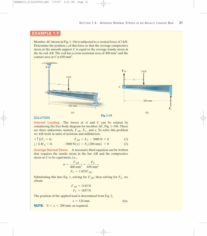
EXAMPLE 1.9
Member AC shown in Fig. 1–19a is subjected to a vertical force of 3 kN.Determine the position x of this force so that the average compressivestress at the smooth support C is equal to the average tensile stress inthe tie rod AB. The rod has a cross-sectional area of and thecontact area at C is 650 mm2.
400 mm2
SOLUTIONInternal Loading. The forces at A and C can be related byconsidering the free-body diagram for member AC, Fig. 1–19b. Thereare three unknowns, namely, and x. To solve this problemwe will work in units of newtons and millimeters.
(1)
(2)
Average Normal Stress. A necessary third equation can be writtenthat requires the tensile stress in the bar AB and the compressivestress at C to be equivalent, i.e.,
Substituting this into Eq. 1, solving for then solving for weobtain
The position of the applied load is determined from Eq. 2,
Ans.
NOTE: as required.0 6 x 6 200 mm,
x = 124 mm
FC = 1857 N
FAB = 1143 N
FC ,FAB ,
FC = 1.625FAB
s =
FAB
400 mm2 =
FC
650 mm2
-3000 N1x2 + FC1200 mm2 = 0d+ ©MA = 0;
FAB + FC - 3000 N = 0+ c ©Fy = 0;
FC ,FAB ,
x
A
B
C
200 mm
(a)
3 kN
Fig. 1–19(b)
x
3 kN
A
200 mm
FAB
FC
HEBBMC01_0132209918.QXD 7/9/07 2:51 PM Page 31

32 CHAPTER 1 STRESS
1.5 Average Shear Stress
Shear stress has been defined in Section 1.3 as the stress component thatacts in the plane of the sectioned area. In order to show how this stresscan develop, we will consider the effect of applying a force F to the bar inFig. 1–20a. If the supports are considered rigid, and F is large enough, itwill cause the material of the bar to deform and fail along the planesidentified by AB and CD. A free-body diagram of the unsupportedcenter segment of the bar, Fig. 1–20b, indicates that the shear force
must be applied at each section to hold the segment inequilibrium. The average shear stress distributed over each sectioned areathat develops this shear force is defined by
(1–7)
Here
average shear stress at the section, which is assumed to be thesame at each point located on the section
internal resultant shear force at the section determined fromthe equations of equilibrium
area at the section
The distribution of average shear stress is shown acting over thesections in Fig. 1–20c. Notice that is in the same direction as V, sincethe shear stress must create associated forces all of which contribute tothe internal resultant force V at the section.
The loading case discussed in Fig. 1–20 is an example of simple ordirect shear, since the shear is caused by the direct action of the appliedload F. This type of shear often occurs in various types of simpleconnections that use bolts, pins, welding material, etc. In all these cases,however, application of Eq. 1–7 is only approximate. A more preciseinvestigation of the shear-stress distribution over the critical sectionoften reveals that much larger shear stresses occur in the material thanthose predicted by this equation. Although this may be the case,application of Eq. 1–7 is generally acceptable for many problems inengineering design and analysis. For example, engineering codes allowits use when considering design sizes for fasteners such as bolts and forobtaining the bonding strength of joints subjected to shear loadings. Inthis regard, two types of shear frequently occur in practice, whichdeserve separate treatment.
tavg
A =
V =
tavg =
tavg =
V
A
V = F>2
F
(a)
BD
AC
(b)
F
VV
(c)
F
tavg
Fig. 1–20
HEBBMC01_0132209918.QXD 7/9/07 2:51 PM Page 32

SECTION 1.5 AVERAGE SHEAR STRESS 33
Single Shear. The steel and wood joints shown in Figs. 1–21a and1–21c, respectively, are examples of single-shear connections and areoften referred to as lap joints. Here we will assume that the members arethin and that the nut in Fig. 1–21a is not tightened to any great extent sofriction between the members can be neglected. Passing a sectionbetween the members yields the free-body diagrams shown inFigs. 1–21b and 1–21d. Since the members are thin, we can neglect themoment created by the force F. Hence for equilibrium, the cross-sectional area of the bolt in Fig. 1–21b and the bonding surface betweenthe members in Fig. 1–21d are subjected only to a single shear force
This force is used in Eq. 1–7 to determine the average shearstress acting on the colored section of Fig. 1–21d.
Double Shear. When the joint is constructed as shown in Fig. 1–22aor 1–22c, two shear surfaces must be considered. These types ofconnections are often called double lap joints. If we pass a sectionbetween each of the members, the free-body diagrams of the centermember are shown in Figs. 1–22b and 1–22d. Here we have a conditionof double shear. Consequently, acts on each sectioned area andthis shear must be considered when applying tavg = V>A.
V = F>2
V = F.
F
F
(a)
F
(b)
V � F V � F
F
(c)
F
(d)
F
Fig. 1–21
The pin on this tractor is subjected to doubleshear.
F
(d)
F
(c)
F
(b)
�V
�V
F
(a)
F2
F2
F2
F2
�V
�V
F2
F2
F2
F2
Fig. 1–22
HEBBMC01_0132209918.QXD 7/9/07 2:51 PM Page 33

34 CHAPTER 1 STRESS
Equilibrium. Consider a volume element of material taken at apoint located on the surface of any sectioned area on which the averageshear stress acts, Fig. 1–23a. If we consider force equilibrium in the ydirection, then
force
stress area
And in a similar manner, force equilibrium in the z direction yieldsFinally, taking moments about the x axis,
moment
force arm
stress area
so that
In other words, force and moment equilibrium requires the shear stressacting on the top face of the element, to be accompanied by shear stressacting on three other faces, Fig. 1–23b. Here all four shear stresses musthave equal magnitude and be directed either toward or away from eachother at opposite edges of the element. This is referred to as thecomplementary property of shear, and under the conditions shown in Fig. 1–23, the material is subjected to pure shear.
Although we have considered here a case of simple shear as caused bythe direct action of a load, in later chapters we will show that shear stresscan also arise indirectly due to the action of other types of loading.
tzy = tœ
zy = tyz = tœ
yz = t
tzy = tyz
-tzy1¢x ¢y2 ¢z + tyz1¢x ¢z2 ¢y = 0©Mx = 0;
tyz = tœ
yz .
tzy = tœ
zy
tzy1¢x ¢y2 - tœ
zy ¢x ¢y = 0©Fy = 0;
Pure shear
(a) (b)
�
Section plane
x
y
z
�y
�z
�xt¿zy
tzy
t¿yz
tyz
t
t
t
t
Fig. 1–23
HEBBMC01_0132209918.QXD 7/9/07 2:51 PM Page 34

SECTION 1.5 AVERAGE SHEAR STRESS 35
Procedure for Analysis
The equation is used to compute only the average shearstress in the material. Application requires the following steps.
Internal Shear
• Section the member at the point where the average shear stress isto be determined.
• Draw the necessary free-body diagram, and calculate the internalshear force V acting at the section that is necessary to hold thepart in equilibrium.
Average Shear Stress
• Determine the sectioned area A, and compute the average shearstress
• It is suggested that be shown on a small volume element ofmaterial located at a point on the section where it is determined.To do this, first draw on the face of the element, coincidentwith the sectioned area A. This shear stress acts in the samedirection as V. The shear stresses acting on the three adjacentplanes can then be drawn in their appropriate directionsfollowing the scheme shown in Fig. 1–23.
tavg
tavg
tavg = V>A.
tavg = V>A
Important Points
• If two parts which are thin or small are joined together, theapplied loads can cause shearing of the material with negligiblebending. If this is the case, it is generally suitable for engineeringanalysis to assume that an average shear stress acts over the cross-sectional area.
• Oftentimes fasteners, such as nails and bolts, are subjected toshear loads. The magnitude of a shear force on the fastener isgreatest along a plane which passes through the surfaces beingjoined. A carefully drawn free-body diagram of a segment of thefastener will enable one to obtain the magnitude and direction ofthis force.
HEBBMC01_0132209918.QXD 7/9/07 2:51 PM Page 35

36 CHAPTER 1 STRESS
EXAMPLE 1.10
The bar shown in Fig. 1–24a has a square cross section for which thedepth and thickness are 40 mm. If an axial force of 800 N is appliedalong the centroidal axis of the bar’s cross-sectional area, determinethe average normal stress and average shear stress acting on thematerial along (a) section plane a–a and (b) section plane b–b.
SOLUTIONPart (a)Internal Loading. The bar is sectioned, Fig. 1–24b, and the internalresultant loading consists only of an axial force for which
Average Stress. The average normal stress is determined from Eq. 1–6.
Ans.
No shear stress exists on the section, since the shear force at thesection is zero.
Ans.
NOTE: The distribution of average normal stress over the crosssection is shown in Fig. 1–24c.
tavg = 0
s =
P
A=
800 N10.04 m210.04 m2 = 500 kPa
P = 800 N.
a
a
b
b
800 N
20 mm60�
(a)
20 mm
(b)
800 N P � 800 N
(c)
500 kPa
500 kPa
Fig. 1–24
HEBBMC01_0132209918.QXD 7/9/07 2:51 PM Page 36

SECTION 1.5 AVERAGE SHEAR STRESS 37
Part (b)Internal Loading. If the bar is sectioned along b–b, the free-bodydiagram of the left segment is shown in Fig. 1–24d. Here both anormal force (N) and shear force (V) act on the sectioned area. Usingx, y axes, we require
or, more directly, using axes,
Solving either set of equations,
Average Stresses. In this case the sectioned area has a thicknessand depth of 40 mm and respectively,Fig. 1–24a. Thus the average normal stress is
Ans.
and the average shear stress is
Ans.
NOTE: The stress distribution is shown in Fig. 1–24e.
tavg =
V
A=
400 N10.04 m210.04619 m2 = 217 kPa
s =
N
A=
692.8 N10.04 m210.04619 m2 = 375 kPa
40 mm>sin 60° = 46.19 mm,
V = 400 N
N = 692.8 N
V - 800 N sin 30° = 0+Q©Fy¿= 0;
N - 800 N cos 30° = 0+R©Fx¿= 0;
y¿x¿,
V sin 60° - N cos 60° = 0+ c ©Fy = 0;
-800 N + N sin 60° + V cos 60° = 0:+ ©Fx = 0;
V
800 N
60�
(d)
30�
y y¿
x¿
x30�
60�N
800 N
(e)
375 kPa
217 kPa
375 kPa
Fig. 1–24 (cont.)
HEBBMC01_0132209918.QXD 7/9/07 2:51 PM Page 37
38 CHAPTER 1 STRESS
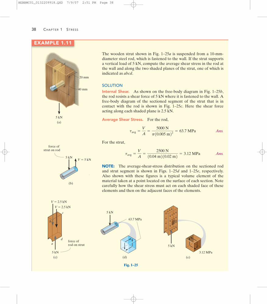
EXAMPLE 1.11
The wooden strut shown in Fig. 1–25a is suspended from a 10-mm-diameter steel rod, which is fastened to the wall. If the strut supportsa vertical load of 5 kN, compute the average shear stress in the rod atthe wall and along the two shaded planes of the strut, one of which isindicated as abcd.
SOLUTIONInternal Shear. As shown on the free-body diagram in Fig. 1–25b,the rod resists a shear force of 5 kN where it is fastened to the wall. Afree-body diagram of the sectioned segment of the strut that is incontact with the rod is shown in Fig. 1–25c. Here the shear forceacting along each shaded plane is 2.5 kN.
Average Shear Stress. For the rod,
Ans.
For the strut,
Ans.
NOTE: The average-shear-stress distribution on the sectioned rodand strut segment is shown in Figs. 1–25d and 1–25e, respectively.Also shown with these figures is a typical volume element of thematerial taken at a point located on the surface of each section. Notecarefully how the shear stress must act on each shaded face of theseelements and then on the adjacent faces of the elements.
tavg =
V
A=
2500 N10.04 m210.02 m2 = 3.12 MPa
tavg =
V
A=
5000 N
p10.005 m22 = 63.7 MPa
c
5 kN
(a)
20 mm
40 mm
b
ad
(b)
5 kNV � 5 kN
force of strut on rod
ad
c
5 kN
V � 2.5 kN
V � 2.5 kN
force ofrod on strut
(c)
b
(d)
5 kN
63.7 MPa
Fig. 1–25
(e)
5 kN
3.12 MPa
HEBBMC01_0132209918.QXD 7/9/07 2:51 PM Page 38

EXAMPLE 1.12
SECTION 1.5 AVERAGE SHEAR STRESS 39
The inclined member in Fig. 1–26a is subjected to a compressive forceof 600 lb. Determine the average compressive stress along the smoothareas of contact defined by AB and BC, and the average shear stressalong the horizontal plane defined by EDB.
(b)
3
45
600 lb
FAB
FBC
(c)
V
360 lb
(d)
3
45
600 lb
160 psi
240 psi
(e)
360 lb
80 psi
(a)
1 in.
3
45
600 lb
1.5 in. 3 in.2 in.
AC
B
DE
Fig. 1–26
SOLUTIONInternal Loadings. The free-body diagram of the inclined memberis shown in Fig. 1–26b. The compressive forces acting on the areas ofcontact are
Also, from the free-body diagram of the top segment of the bottommember, Fig. 1–26c, the shear force acting on the sectioned horizontalplane EDB is
Average Stress. The average compressive stresses along thehorizontal and vertical planes of the inclined member are
Ans.
Ans.
These stress distributions are shown in Fig. 1–26d.The average shear stress acting on the horizontal plane defined by
EDB is
Ans.
This stress is shown distributed over the sectioned area in Fig. 1–26e.
tavg =
360 lb13 in.211.5 in.2 = 80 psi
sBC =
480 lb12 in.211.5 in.2 = 160 psi
sAB =
360 lb11 in.211.5 in.2 = 240 psi
V = 360 lb:+ ©Fx = 0;
FBC - 600 lb A45 B = 0 FBC = 480 lb+ c ©Fy = 0;
FAB - 600 lb A35 B = 0 FAB = 360 lb:+ ©Fx = 0;
HEBBMC01_0132209918.QXD 7/9/07 2:51 PM Page 39

40 CHAPTER 1 STRESS
1–35. The anchor shackle supports a cable force of 600 lb.If the pin has a diameter of 0.25 in., determine the averageshear stress in the pin.
1–37. The thrust bearing is subjected to the loads shown.Determine the average normal stress developed on crosssections through points B, C, and D. Sketch the results on adifferential volume element located at each section.
P R O B L E M S
1–34. The column is subjected to an axial force of 8 kN,which is applied through the centroid of the cross-sectionalarea. Determine the average normal stress acting at sectiona–a. Show this distribution of stress acting over the area’scross section.
*1–36. While running the foot of a 150-lb man ismomentarily subjected to a force which is 5 times hisweight. Determine the average normal stress developed inthe tibia T of his leg at the mid section a–a. The crosssection can be assumed circular, having an outer diameterof 1.75 in. and an inner diameter of 1 in. Assume the fibulaF does not support a load.
0.25 in.
600 lbProb. 1–35
750 lb
a
T F
a
Prob. 1–36
8 kN
aa
75 mm
10 mm
10 mm 10 mm75 mm
70 mm
70 mm
Prob. 1–34
500 N
200 N
65 mm
140 mm
100 mm
B
D
C
150 N150 N
Prob. 1–37
HEBBMC01_0132209918.QXD 7/16/07 5:13 PM Page 40

PROBLEMS 41
1–38. The small block has a thickness of 5 mm. If thestress distribution at the support developed by the loadvaries as shown, determine the force F applied to the block,and the distance d to where it is applied.
1–42. The 50-lb lamp is supported by three steel rodsconnected by a ring at A. Determine which rod is subjectedto the greater average normal stress and compute its value.Take The diameter of each rod is given in the figure.
1–43. Solve Prob. 1–42 for
*1–44. The 50-lb lamp is supported by three steel rodsconnected by a ring at A. Determine the angle of orientation
of AC such that the average normal stress in rod AC istwice the average normal stress in rod AD. What is themagnitude of stress in each rod? The diameter of each rod isgiven in the figure.
u
u = 45°.
u = 30°.1–39. The lever is held to the fixed shaft using a taperedpin AB, which has a mean diameter of 6 mm. If a couple isapplied to the lever, determine the average shear stress inthe pin between the pin and lever.
1–41. The cinder block has the dimensions shown. If it is subjected to a centrally applied force of determine the average normal stress in the material. Showthe result acting on a differential volume element of thematerial.
P = 800 lb,
60 mm
120 mm
40 MPa
60 MPa
F
d
180 mm
Prob. 1–38
20 N 20 N
250 mm 250 mm
12 mm
A
B
Prob. 1–390.25 in.
A
D C
B0.35 in.
0.3 in.u45�
Probs. 1–42/43/44
1 in.
1 in.4 in. 2 in.
2 in.1 in.
1 in.2 in.
3 in.
3 in.
P
Probs. 1–40/41
*1–40. The cinder block has the dimensions shown. If thematerial fails when the average normal stress reaches 120 psi,determine the largest centrally applied vertical load P it cansupport.
HEBBMC01_0132209918.QXD 7/9/07 2:51 PM Page 41

42 CHAPTER 1 STRESS
1–45. The shaft is subjected to the axial force of 30 kN. Ifthe shaft passes through the 53-mm diameter hole in thefixed support A, determine the bearing stress acting on thecollar C. Also, what is the average shear stress acting alongthe inside surface of the collar where it is fixed connected tothe 52-mm diameter shaft?
1–49. The open square butt joint is used to transmit aforce of 50 kip from one plate to the other. Determine theaverage normal and average shear stress components thatthis loading creates on the face of the weld, section AB.
1–46. The two steel members are joined together using a60° scarf weld. Determine the average normal and averageshear stress resisted in the plane of the weld.
*1–48. The board is subjected to a tensile force of 85 lb.Determine the average normal and average shear stressdeveloped in the wood fibers that are oriented alongsection a–a at 15° with the axis of the board.
30 mm
25 mm
60�
8 kN8 kN
Prob. 1–46
15�3 in.
a
1 in.
85 lb85 lb
a
Prob. 1–48
52�
0.5 in.
Prob. 1–50
10 mm
30 kN
52 mm
60 mm
40 mm
53 mm
AC
Prob. 1–45
C
A B
20
30 mm40 mm
775 N
Prob. 1–47
30�
30�
50 kip
50 kip
2 in.
6 in.A
B
Prob. 1–49
1–47. The J hanger is used to support the pipe such thatthe force on the vertical bolt is 775 N. Determine theaverage normal stress developed in the bolt BC if the bolthas a diameter of 8 mm. Assume A is a pin.
1–50. The specimen failed in a tension test at an angle of52° when the axial load was 19.80 kip. If the diameter of thespecimen is 0.5 in., determine the average normal andaverage shear stress acting on the area of the inclinedfailure plane. Also, what is the average normal stress actingon the cross section when failure occurs?
HEBBMC01_0132209918.QXD 7/9/07 2:51 PM Page 42

PROBLEMS 43
1–51. A tension specimen having a cross-sectional area Ais subjected to an axial force P. Determine the maximumaverage shear stress in the specimen and indicate theorientation of a section on which it occurs.u
1–55. The row of staples AB contained in the stapler isglued together so that the maximum shear stress the gluecan withstand is Determine the minimumforce F that must be placed on the plunger in order to shearoff a staple from its row and allow it to exit undeformedthrough the groove at C. The outer dimensions of the stapleare shown in the figure. It has a thickness of 0.05 in. Assumeall the other parts are rigid and neglect friction.
tmax = 12 psi.
*1–56. Rods AB and BC have diameters of 4 mm and 6 mm,respectively. If the load of 8 kN is applied to the ring at B,determine the average normal stress in each rod if
1–57. Rods AB and BC have diameters of 4 mm and 6 mm,respectively. If the vertical load of 8 kN is applied to the ringat B, determine the angle of rod BC so that the averagenormal stress in each rod is equivalent. What is this stress?
u
u = 60°.
*1–52. The joint is subjected to the axial member force of5 kN. Determine the average normal stress acting onsections AB and BC. Assume the member is smooth and is50-mm thick.
1–54. The two members used in the construction of anaircraft fuselage are joined together using a 30° fish-mouthweld. Determine the average normal and average shear stresson the plane of each weld. Assume each inclined planesupports a horizontal force of 400 lb.
P
u
P
A
Prob. 1–51
5 kN
40 mm
A
CB
50 mm
60�
45�
Prob. 1–52
800 lb 800 lb
30�
1 in.1 in.
1.5 in. 30�
Prob. 1–54
1–53. The yoke is subjected to the force and couplemoment. Determine the average shear stress in the boltacting on the cross sections through A and B. The bolt has adiameter of 0.25 in. Hint: The couple moment is resisted bya set of couple forces developed in the shank of the bolt.
500 lb
80 lb�ft
2 in.2.5 in.A
B60�
Prob. 1–53
F
0.5 in.
0.3 in.
C
A B
Prob. 1–55
8 kN
u
C
BA
Probs. 1–56/57
HEBBMC01_0132209918.QXD 7/9/07 2:51 PM Page 43

44 CHAPTER 1 STRESS
1–58. The bars of the truss each have a cross-sectionalarea of Determine the average normal stress ineach member due to the loading State whetherthe stress is tensile or compressive.
1–59. The bars of the truss each have a cross-sectionalarea of If the maximum average normal stress in anybar is not to exceed 20 ksi, determine the maximum magnitudeP of the loads that can be applied to the truss.
1.25 in2.
P = 8 kip.1.25 in2.
1–63. The railcar docklight is supported by the diameter pin at A. If the lamp weighs 4 lb, and the extensionarm AB has a weight of , determine the averageshear stress in the pin needed to support the lamp. Hint:The shear force in the pin is caused by the couple momentrequired for equilibrium at A.
0.5 lb>ft18-in.-
*1–64. The two-member frame is subjected to thedistributed loading shown. Determine the average normalstress and average shear stress acting at sections a–a andb–b. Member CB has a square cross section of 35 mm oneach side. Take w = 8 kN>m.
*1–60. The plug is used to close the end of the cylindricaltube that is subjected to an internal pressure of Determine the average shear stress which the glue exerts onthe sides of the tube needed to hold the cap in place.
p = 650 Pa.
1–62. Solve Prob. 1–61 for pin B. The pin is subjected todouble shear and has a diameter of 0.2 in.
3 ft
4 ft 4 ft
P0.75 P
E DA
B C
Probs. 1–58/593 ft
1.25 in.
BA
Prob. 1–63
P 40 mm35 mm
25 mm
Prob. 1–60
A
20 lb
20 lb
5 in.1.5 in. 2 in. 1 in.
E C
B D
Probs. 1–61/62
4 m
BA
C
3 m
b
b
a
a
wProb. 1–64
1–61. The crimping tool is used to crimp the end of thewire E. If a force of 20 lb is applied to the handles,determine the average shear stress in the pin at A. The pinis subjected to double shear and has a diameter of 0.2 in.Only a vertical force is exerted on the wire.
HEBBMC01_0132209918.QXD 7/9/07 2:51 PM Page 44

PROBLEMS 45
1–67. The beam is supported by a pin at A and a short linkBC. If determine the average shear stressdeveloped in the pins at A, B, and C. All pins are in doubleshear as shown, and each has a diameter of 18 mm.
*1–68. The beam is supported by a pin at A and a shortlink BC. Determine the maximum magnitude P of the loadsthe beam will support if the average shear stress in each pinis not to exceed 80 MPa. All pins are in double shear asshown, and each has a diameter of 18 mm.
P = 15 kN,
P2P1Pn
AmA2A1
d1
d2
dn
L1 L2 Lm
x
Prob. 1–66
30C
1 m
P 4P 4P 2P
1.5 m 1.5 m
AB
0.5m 0.5m
Probs. 1–67/68
1–65. Member A of the timber step joint for a truss issubjected to a compressive force of 5 kN. Determine theaverage normal stress acting in the hanger rod C which hasa diameter of 10 mm and in member B which has athickness of 30 mm.
C
10 mm
FC
mm40 mm30�
60�
5 kN
FB
E
AAA
B
D F
Prob. 1–65
A
C
B
1.5 ft2 ft
0.5 ft
200 lb
u
Prob. 1–69
�1–66. Consider the general problem of a bar made fromm segments, each having a constant cross-sectional area and length If there are n loads on the bar as shown,write a computer program that can be used to determinethe average normal stress at any specified location x. Showan application of the program using the values
A2 = 1 in2.P2 = -300 lb,d2 = 6 ft,L2 = 2 ft,A1 = 3 in2,P1 = 400 lb,d1 = 2 ft,L1 = 4 ft,
Lm .Am
1–69. The frame is subjected to the load of 200 lb.Determine the average shear stress in the bolt at A as afunction of the bar angle Plot this function, and indicate the values of for which this stress is aminimum. The bolt has a diameter of 0.25 in. and issubjected to single shear.
u
0 … u … 90°,u.
HEBBMC01_0132209918.QXD 7/9/07 2:51 PM Page 45

46 CHAPTER 1 STRESS
1–70. The jib crane is pinned at A and supports a chainhoist that can travel along the bottom flange of the beam,
If the hoist is rated to support a maximumof 1500 lb, determine the maximum average normal stressin the tie rod BC and the maximum averageshear stress in the pin at B.5
8-in.-diameter
34-in.-diameter
1 ft … x … 12 ft.
*1–72. The boom has a uniform weight of 600 lb and ishoisted into position using the cable BC. If the cable has adiameter of 0.5 in., plot the average normal stress in thecable as a function of the boom position for 0° … u … 90°.u
C
10 ft
x
A
B
30�
D
1500 lb
Prob. 1–70
PP
A
u
Prob. 1–71
3 ft
B
A
3 ft
F C
�
Prob. 1–72
x
w � 8 kN/m6 kN
3 kN
0.5 m 0.75 m
Probs. 1–73/74
1–71. The bar has a cross-sectional area A and is subjectedto the axial load P. Determine the average normal andaverage shear stresses acting over the shaded section, whichis oriented at from the horizontal. Plot the variation ofthese stresses as a function of u 10 … u … 90°2.
u
1–73. The bar has a cross-sectional area ofIf it is subjected to a uniform axial distributed loading alongits length and to two concentrated loads as shown, determinethe average normal stress in the bar as a function of x for
1–74. The bar has a cross-sectional area of If it is subjected to a uniform axial distributed loading alongits length and to two concentrated loads as shown,determine the average normal stress in the bar as a functionof x for 0.5 m 6 x … 1.25 m.
400110-62 m2.
0 6 x … 0.5 m.
400 110-62 m2.
HEBBMC01_0132209918.QXD 7/9/07 2:51 PM Page 46

PROBLEMS 47
1–75. The column is made of concrete having a density ofAt its top B it is subjected to an axial
compressive force of 15 kN. Determine the average normalstress in the column as a function of the distance zmeasured from its base. Note: The result will be useful onlyfor finding the average normal stress at a section removedfrom the ends of the column, because of localizeddeformation at the ends.
2.30 Mg>m3.1–77. The pedestal supports a load P at its center. If thematerial has a mass density determine the radial dimensionr as a function of z so that the average normal stress in thepedestal remains constant. The cross section is circular.
r,
z
x y
15 kN
4 m
180 mm
z
B
Prob. 1–75
4 m
B
AC
3 m
b b
w
Prob. 1–76 x
V
L2
L2
Prob. 1–79
*1–76. The two-member frame is subjected to thedistributed loading shown. Determine the largest intensity
of the uniform loading that can be applied to the framewithout causing either the average normal stress or theaverage shear stress at section b–b to exceed and respectively. Member CB has a squarecross-section of 30 mm on each side.
t = 16 MPa,s = 15 MPa
w
z
r
P
r1
Prob. 1–77
r � 0.5e�0.08y2
y
3 m
0.5 m
r
Prob. 1–78
1–78. The radius of the pedestal is defined by where y is given in meters. If the material
has a density of determine the average normalstress at the support.
2.5 Mg>m3,10.5e-0.08y22 m,
r =
1–79. The uniform bar, having a cross-sectional area of Aand mass per unit length of m, is pinned at its center. If it isrotating in the horizontal plane at a constant angular rate of
determine the average normal stress in the bar as afunction of x.v,
HEBBMC01_0132209918.QXD 7/9/07 2:51 PM Page 47

48 CHAPTER 1 STRESS
1.6 Allowable Stress
An engineer in charge of the design of a structural member ormechanical element must restrict the stress in the material to a level thatwill be safe. Furthermore, a structure or machine that is currently in usemay, on occasion, have to be analyzed to see what additional loadings itsmembers or parts can support. So again it becomes necessary to performthe calculations using a safe or allowable stress.
To ensure safety, it is necessary to choose an allowable stress thatrestricts the applied load to one that is less than the load the member canfully support. There are several reasons for this. For example, the loadfor which the member is designed may be different from actual loadingsplaced on it. The intended measurements of a structure or machine maynot be exact, due to errors in fabrication or in the assembly of itscomponent parts. Unknown vibrations, impact, or accidental loadingscan occur that may not be accounted for in the design. Atmosphericcorrosion, decay, or weathering tend to cause materials to deteriorateduring service. And lastly, some materials, such as wood, concrete, orfiber-reinforced composites, can show high variability in mechanicalproperties.
One method of specifying the allowable load for the design or analysisof a member is to use a number called the factor of safety. The factor ofsafety (F.S.) is a ratio of the failure load divided by the allowableload, Here is found from experimental testing of thematerial, and the factor of safety is selected based on experience so thatthe above mentioned uncertainties are accounted for when the memberis used under similar conditions of loading and geometry. Statedmathematically,
(1–8)
If the load applied to the member is linearly related to the stressdeveloped within the member, as in the case of using and
then we can express the factor of safety as a ratio of thefailure stress (or ) to the allowable stress (or );* that is,
(1–9)
or
(1–10)F.S. =
tfail
tallow
F.S. =
sfail
sallow
tallowsallowtfailsfail
tavg = V>A,s = P>A
F.S. =
Ffail
Fallow
FfailFallow .Ffail
*In some cases, such as columns, the applied load is not linearly related to stress andtherefore only Eq. 1–8 can be used to determine the factor of safety. See Chapter 13.
Appropriate factors of safety must beconsidered when designing cranes and cablesused to transfer heavy loads.
HEBBMC01_0132209918.QXD 7/9/07 2:51 PM Page 48

SECTION 1.7 DESIGN OF SIMPLE CONNECTIONS 49
In any of these equations, the factor of safety is chosen to be greaterthan 1 in order to avoid the potential for failure. Specific values dependon the types of materials to be used and the intended purpose of thestructure or machine. For example, the F.S. used in the design of aircraftor space-vehicle components may be close to 1 in order to reduce theweight of the vehicle. On the other hand, in the case of a nuclear powerplant, the factor of safety for some of its components may be as high as 3since there may be uncertainties in loading or material behavior. Ingeneral, however, factors of safety and therefore the allowable loads orstresses for both structural and mechanical elements have become wellstandardized, since their design uncertainties have been reasonablyevaluated. Their values, which can be found in design codes andengineering handbooks, are intended to form a balance of ensuringpublic and environmental safety and providing a reasonable economicsolution to design.
1.7 Design of Simple Connections
By making simplifying assumptions regarding the behavior of thematerial, the equations and can often be used toanalyze or design a simple connection or a mechanical element. Inparticular, if a member is subjected to a normal force at a section, itsrequired area at the section is determined from
(1–11)
On the other hand, if the section is subjected to a shear force, then therequired area at the section is
(1–12)
As discussed in Sec. 1.6, the allowable stress used in each of theseequations is determined either by applying a factor of safety to aspecified normal or shear stress or by finding these stresses directly froman appropriate design code.
We will now discuss four common types of problems for which theabove equations can be used for design.
A =
Vtallow
A =
Psallow
tavg = V>As = P>A
HEBBMC01_0132209918.QXD 7/9/07 2:51 PM Page 49

50 CHAPTER 1 STRESS
Cross-Sectional Area of a Connector Subjected toShear. Often bolts or pins are used to connect plates, boards, orseveral members together. For example, consider the lap joint shown inFig. 1–28a. If the bolt is loose or the clamping force of the bolt isunknown, it is safe to assume that any frictional force between the platesis negligible. As a result, the free-body diagram for a section passingbetween the plates and through the bolt is shown in Fig. 1–28b. The boltis subjected to a resultant internal shear force of at this crosssection. Assuming that the shear stress causing this force is uniformlydistributed over the cross section, the bolt’s cross-sectional area A isdetermined as shown in Fig. 1–28c.
Required Area to Resist Bearing. A normal stress that isproduced by the compression of one surface against another is called abearing stress. If this stress becomes large enough, it may crush or locallydeform one or both of the surfaces. Hence, in order to prevent failure itis necessary to determine the proper bearing area for the material usingan allowable bearing stress. For example, the area A of the column baseplate B shown in Fig. 1–29 is determined from the allowable bearingstress of the concrete using This assumes, of course,that the allowable bearing stress for the concrete is smaller than that ofthe base plate material, and furthermore the bearing stress is uniformlydistributed between the plate and the concrete as shown in the figure.
A = P>1sb2allow .
V = P
P
P
(a)
Fig. 1–28
P
(b)
V � P
(c)
Uniform shear stress
P
A �
tallow
Ptallow
B
(b)allow
P
Uniform normalstress distribution
A �P
(b)allow
Fig. 1–29
(a)
P
a
a
P
Fig. 1–27
Uniform normal stress
P
(b)
A �
allow
Pallow
Cross-Sectional Area of a Tension Member. The cross-sectional area of a prismatic member subjected to a tension force can bedetermined provided the force has a line of action that passes throughthe centroid of the cross section. For example, consider the “eye bar”shown in Fig. 1–27a. At the intermediate section a–a, the stressdistribution is uniform over the cross section and the shaded area A isdetermined, as shown in Fig. 1–27b.
HEBBMC01_0132209918.QXD 7/9/07 2:51 PM Page 50

SECTION 1.7 DESIGN OF SIMPLE CONNECTIONS 51
Required Area to Resist Shear Caused by Axial Load.Occasionally rods or other members will be supported in such a way thatshear stress can be developed in the member even though the membermay be subjected to an axial load. An example of this situation wouldbe a steel rod whose end is encased in concrete and loaded as shown inFig. 1–30a. A free-body diagram of the rod, Fig. 1–30b, shows that shearstress acts over the area of contact of the rod with the concrete. This areais where d is the rod’s diameter and l is the length of embedment.Although the actual shear-stress distribution along the rod would bedifficult to determine, if we assume it is uniform, we can use to calculate l, provided we know d and Fig. 1–30b.tallow ,
A = V>tallow
1pd2l,
(a)
P
d
Uniform shear stress
(b)
allow
P
t
l � —————P
allow dt p
Fig. 1–30
Procedure for Analysis
When solving problems using the average normal and shear stressequations, a careful consideration should first be made as to thesection over which the critical stress is acting. Once this section ismade, the member must then be designed to have a sufficient area atthe section to resist the stress that acts on it. To determine this area,application requires the following steps.
Internal Loading
• Section the member through the area and draw a free-bodydiagram of a segment of the member. The internal resultant force atthe section is then determined using the equations of equilibrium.
Required Area
• Provided the allowable stress is known or can be determined, therequired area needed to sustain the load at the section is thencomputed from or A = V>tallow .A = P>sallow
Important Points
• Design of a member for strength is based on selecting anallowable stress that will enable it to safely support its intendedload. There are many unknown factors that can influence theactual stress in a member and so, depending upon the intendeduses of the member, a factor of safety is applied to obtain theallowable load the member can support.
• The four cases illustrated in this section represent just a few of themany applications of the average normal and shear stressformulas used for engineering design and analysis. Wheneverthese equations are applied, however, it is important to be awarethat the stress distribution is assumed to be uniformly distributedor “averaged” over the section.
HEBBMC01_0132209918.QXD 7/9/07 2:51 PM Page 51

52 CHAPTER 1 STRESS
EXAMPLE 1.13
The two members are pinned together at B as shown in Fig. 1–31a.Top views of the pin connections at A and B are also given in thefigure. If the pins have an allowable shear stress of and the allowable tensile stress of rod CB is determine to the nearest the smallest diameter of pins A and Band the diameter of rod CB necessary to support the load.
116 in.
1st2allow = 16.2 ksi,tallow = 12.5 ksi
SOLUTIONRecognizing CB to be a two-force member, the free-body diagram ofmember AB along with the computed reactions at A and B is shownin Fig. 1–31b. As an exercise, verify the computations and notice thatthe resultant force at A must be used for the design of pin A, since thisis the shear force the pin resists.
B
3 kip 35
4
C
2 ft4 ft
A
AB
(a)
Fig. 1–31
4 ftA
(b)
3 kip
B2 ft
1 kip
3.33 kip
2.85 kip
2.67 kip
20.6�
35
4
HEBBMC01_0132209918.QXD 7/9/07 2:51 PM Page 52

SECTION 1.7 DESIGN OF SIMPLE CONNECTIONS 53
Diameter of the Pins. From Fig. 1–31a and the free-body diagramsof the sectioned portion of each pin in contact with member AB, Fig. 1–31c, it is seen that pin A is subjected to double shear, whereaspin B is subjected to single shear. Thus,
Although these values represent the smallest allowable pin diameters,a fabricated or available pin size will have to be chosen. We willchoose a size larger to the nearest as required.
Ans.
Ans.
Diameter of Rod. The required diameter of the rod throughout itsmidsection is thus,
We will choose
Ans.dBC =916 in. = 0.5625 in.
dBC = 0.512 in.
ABC =
P
1st2allow=
3.333 kip
16.2 kip>in2 = 0.2058 in2= p¢dBC
2
4≤
dB =58 in. = 0.625 in.
dA =716 in. = 0.4375 in.
116 in.
AB =
VB
tallow=
3.333 kip
12.5 kip>in2 = 0.2667 in2= p¢dB
2
4≤ dB = 0.583 in.
AA =
VA
tallow=
1.425 kip
12.5 kip>in2 = 0.1139 in2= p¢dA
2
4≤ dA = 0.381 in.
(c)
1.425 kip
1.425 kip
2.85 kip
3.33 kip
3.33 kip
Pin at BPin at A
Fig. 1–31 (cont.)
HEBBMC01_0132209918.QXD 7/9/07 2:51 PM Page 53
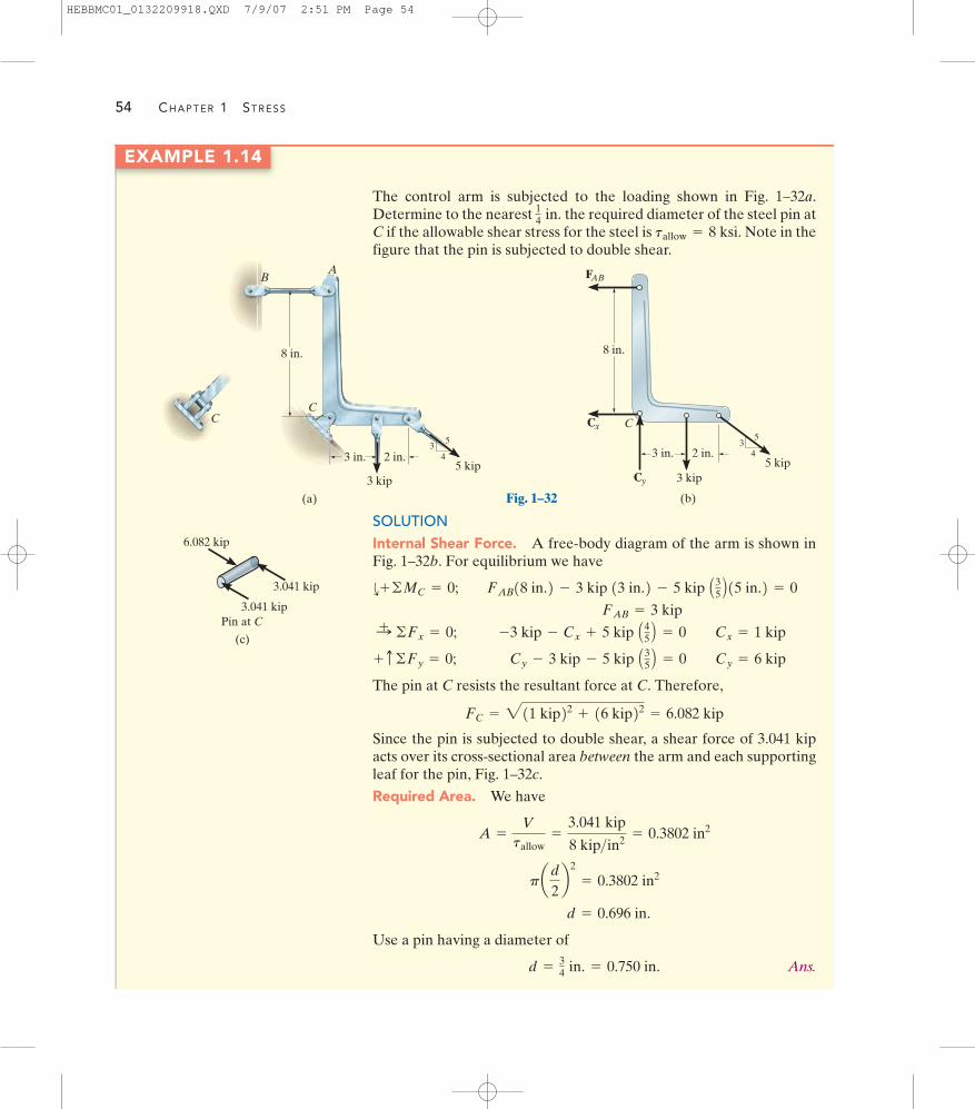
54 CHAPTER 1 STRESS
EXAMPLE 1.14
The control arm is subjected to the loading shown in Fig. 1–32a.Determine to the nearest the required diameter of the steel pin atC if the allowable shear stress for the steel is Note in thefigure that the pin is subjected to double shear.
tallow = 8 ksi.
14 in.
SOLUTIONInternal Shear Force. A free-body diagram of the arm is shown inFig. 1–32b. For equilibrium we have
The pin at C resists the resultant force at C. Therefore,
Since the pin is subjected to double shear, a shear force of 3.041 kipacts over its cross-sectional area between the arm and each supportingleaf for the pin, Fig. 1–32c.
Required Area. We have
Use a pin having a diameter of
Ans.d =34 in. = 0.750 in.
d = 0.696 in.
pad
2b2
= 0.3802 in2
A =
Vtallow
=
3.041 kip
8 kip>in2 = 0.3802 in2
FC = 211 kip22 + 16 kip22 = 6.082 kip
Cy - 3 kip - 5 kip A35 B = 0 Cy = 6 kip+ c ©Fy = 0;
-3 kip - Cx + 5 kip A45 B = 0 Cx = 1 kip:+ ©Fx = 0;
FAB = 3 kip
FAB18 in.2 - 3 kip 13 in.2 - 5 kip A35 B15 in.2 = 0d+ ©MC = 0;
(a)
C
35
42 in.3 in.
8 in.
A
C
3 kip5 kip
B
Fig. 1–32
35
42 in.3 in.
8 in.
Cx
3 kip5 kip
FAB
Cy
(b)
C
(c)
3.041 kip
3.041 kip
6.082 kip
Pin at C
HEBBMC01_0132209918.QXD 7/9/07 2:51 PM Page 54

EXAMPLE 1.15
SECTION 1.7 DESIGN OF SIMPLE CONNECTIONS 55
The suspender rod is supported at its end by a fixed-connected circulardisk as shown in Fig. 1–33a. If the rod passes through a 40-mm-diameter hole, determine the minimum required diameter of the rodand the minimum thickness of the disk needed to support the 20-kNload. The allowable normal stress for the rod is andthe allowable shear stress for the disk is tallow = 35 MPa.
sallow = 60 MPa,
SOLUTIONDiameter of Rod. By inspection, the axial force in the rod is 20 kN.Thus the required cross-sectional area of the rod is
So that
Ans.
Thickness of Disk. As shown on the free-body diagram of the coresection of the disk, Fig. 1–33b, the material at the sectioned area mustresist shear stress to prevent movement of the disk through the hole. Ifthis shear stress is assumed to be distributed uniformly over thesectioned area, then, since we have
Since the sectioned area the required thicknessof the disk is
Ans.t =
0.5714110-32 m2
2p10.02 m2 = 4.55110-32 m = 4.55 mm
A = 2p10.02 m21t2,A =
Vtallow
=
2011032 N3511062 N>m2 = 0.571110-32 m2
V = 20 kN,
d = 0.0206 m = 20.6 mm
A = p¢d2
4≤ = 0.3333110-22 m2
A =
Psallow
=
2011032 N6011062 N>m2 = 0.3333110-32 m2
20 kN
t
d
(a)
40 mm
Fig. 1–33
20 kN
A allow
(b)
40 mm
t
HEBBMC01_0132209918.QXD 7/9/07 2:51 PM Page 55

56 CHAPTER 1 STRESS
EXAMPLE 1.16
An axial load on the shaft shown in Fig. 1–34a is resisted by the collarat C, which is attached to the shaft and located on the right side of thebearing at B. Determine the largest value of P for the two axial forcesat E and F so that the stress in the collar does not exceed an allowablebearing stress at C of and the average normalstress in the shaft does not exceed an allowable tensile stress of1st2allow = 55 MPa.
1sb2allow = 75 MPa
80 mm
60 mmP
A
FP2
CE
B
(a)
20 mm
P2 P
(b)
3P
3P
(d)
C
(c)
AxialLoad
Position
3P2P
Fig. 1–34
SOLUTIONTo solve the problem we will determine P for each possible failurecondition. Then we will choose the smallest value. Why?
Normal Stress. Using the method of sections, the axial load withinregion FE of the shaft is 2P, whereas the largest axial load, 3P, occurswithin region EC, Fig. 1–34b. The variation of the internal loading isclearly shown on the normal-force diagram, Fig. 1–34c. Since the cross-sectional area of the entire shaft is constant, region EC will be subjectedto the maximum average normal stress. Applying Eq. 1–11, we have
Bearing Stress. As shown on the free-body diagram in Fig. 1–34d,the collar at C must resist the load of 3P, which acts over a bearingarea of Thus,
By comparison, the largest load that can be applied to the shaft issince any load larger than this will cause the allowable
normal stress in the shaft to be exceeded.P = 51.8 kN,
P = 55.0 kN
7511062 N>m2=
3P
2.199110-32 m2A =
Psallow
;
Ab = [p10.04 m22 - p10.03 m22] = 2.199110-32 m2.
P = 51.8 kN
5511062 N>m2=
3P
p10.03 m22sallow =
P
A
HEBBMC01_0132209918.QXD 7/9/07 2:51 PM Page 56

EXAMPLE 1.17
SECTION 1.7 DESIGN OF SIMPLE CONNECTIONS 57
The rigid bar AB shown in Fig. 1–35a is supported by a steel rod AChaving a diameter of 20 mm and an aluminum block having a cross-sectional area of The 18-mm-diameter pins at A and C aresubjected to single shear. If the failure stress for the steel and aluminum is
and respectively, and the failureshear stress for each pin is determine the largest load Pthat can be applied to the bar. Apply a factor of safety of
SOLUTIONUsing Eqs. 1–9 and 1–10, the allowable stresses are
The free-body diagram for the bar is shown in Fig. 1–35b. There arethree unknowns. Here we will apply the equations of equilibrium so asto express and in terms of the applied load P. We have
(1)(2)
We will now determine each value of P that creates the allowablestress in the rod, block, and pins, respectively.
Rod AC. This requires
Using Eq. 1,
P =
1106.8 kN212 m21.25 m
= 171 kN
FAC = 1sst2allow1AAC2 = 34011062 N>m2 [p10.01 m22] = 106.8 kN
FB12 m2 - P10.75 m2 = 0d+ ©MA = 0; P11.25 m2 - FAC12 m2 = 0d+ ©MB = 0;
FBFAC
tallow =
tfail
F.S.=
900 MPa2
= 450 MPa
1sal2allow =
1sal2fail
F.S.=
70 MPa2
= 35 MPa
1sst2allow =
1sst2fail
F.S.=
680 MPa2
= 340 MPa
F.S. = 2.tfail = 900 MPa,1sal2fail = 70 MPa,1sst2fail = 680 MPa
1800 mm2.
Block B. In this case,
FB = 1sal2allow AB = 3511062 N>m2 [1800 mm2 110-62 m2>mm2] = 63.0 kN
Using Eq. 2,
Pin A or C. Here
From Eq. 1,
By comparison, when P reaches its smallest value (168 kN), itdevelops the allowable normal stress in the aluminum block. Hence,
Ans.P = 168 kN
P =
114.5 kN 12 m21.25 m
= 183 kN
V = FAC = tallow A = 45011062 N>m2 [p10.009 m22] = 114.5 kN
P =
163.0 kN212 m20.75 m
= 168 kN
2 m
A
0.75 m
(a)
Aluminum
Steel P
B
C
(b)
A
0.75 m
P
1.25 mB
FB
FAC
Fig. 1–35
HEBBMC01_0132209918.QXD 7/9/07 2:51 PM Page 57

58 CHAPTER 1 STRESS
1–81. The joint is fastened together using two bolts.Determine the required diameter of the bolts if the failureshear stress for the bolts is Use a factor ofsafety for shear of F.S. = 2.5.
tfail = 350 MPa.
1–83. The lever is attached to the shaft A using a key thathas a width d and length of 25 mm. If the shaft is fixed and avertical force of 200 N is applied perpendicular to thehandle, determine the dimension d if the allowable shearstress for the key is tallow = 35 MPa.
P R O B L E M S
*1–80. Member B is subjected to a compressive force of800 lb. If A and B are both made of wood and are thick,determine to the nearest the smallest dimension h ofthe support so that the average shear stress does not exceedtallow = 300 psi.
14
in.
38
in.
1–82. The rods AB and CD are made of steel having afailure tensile stress of Using a factor ofsafety of for tension, determine their smallestdiameter so that they can support the load shown. Thebeam is assumed to be pin connected at A and C.
F.S. = 1.75sfail = 510 MPa.
800 lbB
hA
12
513
Prob. 1–80
500 mm
20 mm
daa
A
200 N
Prob. 1–83
80 kN
40 kN
30 mm
30 mm
40 kN
Prob. 1–81
B
A
D
C
4 kN
6 kN5 kN
3 m2 m2 m 3 m
Prob. 1–82
HEBBMC01_0132209918.QXD 7/9/07 2:51 PM Page 58

PROBLEMS 59
1–85. The fillet weld size If the joint isassumed to fail by shear on both sides of the block along theshaded plane, which is the smallest cross section, determinethe largest force P that can be applied to the plate. Theallowable shear stress for the weld material is tallow = 14 ksi.
a = 0.25 in.
*1–84. The fillet weld size a is determined by computingthe average shear stress along the shaded plane, which hasthe smallest cross section. Determine the smallest size aof the two welds if the force applied to the plate is
The allowable shear stress for the weld materialis tallow = 14 ksi.P = 20 kip.
a
45�
a
P 4 in.
Prob. 1–84
a
45�
a
P 4 in.
Prob. 1–85
1–86. The eye bolt is used to support the load of 5 kip.Determine its diameter d to the nearest and the requiredthickness h to the nearest of the support so that thewasher will not penetrate or shear through it. The allowablenormal stress for the bolt is and the allowableshear stress for the supporting material is tallow = 5 ksi.
sallow = 21 ksi
18
in.
18
in.
1–87. The frame is subjected to the load of 1.5 kip.Determine the required diameter of the pins at A and B ifthe allowable shear stress for the material is Pin A is subjected to double shear, whereas pin B issubjected to single shear.
tallow = 6 ksi.
1 in.
d
5 kip
h
Prob. 1–86
B
C
5 ft 5 ft
1.5 kip
5 ft
2 ft
DA
Prob. 1–87
HEBBMC01_0132209918.QXD 7/9/07 2:51 PM Page 59

60 CHAPTER 1 STRESS
*1–88. The two steel wires AB and AC are used to supportthe load. If both wires have an allowable tensile stress of
determine the required diameter of eachwire if the applied load is P = 5 kN.sallow = 200 MPa,
60�4
35
P
B
A
C
Prob. 1–88
1–89. The two steel wires AB and AC are used to supportthe load. If both wires have an allowable tensile stress of
and wire AB has a diameter of 6 mm andAC has a diameter of 4 mm, determine the greatest force Pthat can be applied to the chain before one of the wires fails.
sallow = 180 MPa,
20 ft
f
u
A
B
d
Probs. 1–90/91
60�4
35
P
B
A
C
Prob. 1–89
1–91. The boom is supported by the winch cable that hasan allowable normal stress of If it isrequired that it be able to slowly lift 5000 lb, from to determine the smallest diameter of the cable tothe nearest The boom AB has a length of 20 ft.Neglect the size of the winch. Set d = 12 ft.
116 in.
u = 50°,u = 20°
sallow = 24 ksi.
*1–92. The frame is subjected to the distributed loading of2 kN�m. Determine the required diameter of the pins at Aand B if the allowable shear stress for the material is
Both pins are subjected to double shear.tallow = 100 MPa.
AB
C
2 kN/m
3 m
Prob. 1–92
1–90. The boom is supported by the winch cable that has adiameter of 0.25 in. and an allowable normal stress of
Determine the greatest load that can besupported without causing the cable to fail when and Neglect the size of the winch.f = 45°.
u = 30°sallow = 24 ksi.
M01_HIBB9915_07_SE_C01.QXD 10/5/07 12:56 PM Page 60

PROBLEMS 61
P � 150 kN
� 30 mm
t
d1
d2
d3
Prob. 1–93
1–93. Determine the smallest dimensions of the circularshaft and circular end cap if the load it is required tosupport is The allowable tensile stress,bearing stress, and shear stress is
and tallow = 115 MPa.1sb2allow = 275 MPa,1st2allow = 175 MPa,
P = 150 kN.
1–94. If the allowable bearing stress for the material underthe supports at A and B is determine thesize of square bearing plates and required to supportthe loading. Take Dimension the plates to thenearest The reactions at the supports are vertical.
1–95. If the allowable bearing stress for the material underthe supports at A and B is determine themaximum load P that can be applied to the beam. Thebearing plates and have square cross sections of
and respectively.4 in. * 4 in.,2 in. * 2 in.B¿A¿
1sb2allow = 400 psi,
12 in.
P = 1.5 kip.B¿A¿
1sb2allow = 400 psi,
A B
7.5 ft
2 kip 2 kip
3 kip
2 kipP
5 ft 5 ft 5 ft
A¿ B¿
Probs. 1–94/95
*1–96. Determine the required cross-sectional area ofmember BC and the diameter of the pins at A and B if theallowable normal stress is and the allowableshear stress is tallow = 4 ksi.
sallow = 3 ksi
C
60�
2 ft 4 ft 2 ft
B
1500 lb 1500 lb
A
Prob. 1–96
1–97. The assembly consists of three disks A, B, and Cthat are used to support the load of 140 kN. Determine thesmallest diameter of the top disk, the diameter withinthe support space, and the diameter of the hole in thebottom disk. The allowable bearing stress for the materialis and allowable shear stress istallow = 125 MPa.1sallow2b = 350 MPa
d3
d2d1
10 mm
20 mm
140 kN
d2
d3
d1
AB
C
Prob. 1–97
HEBBMC01_0132209918.QXD 7/9/07 2:51 PM Page 61
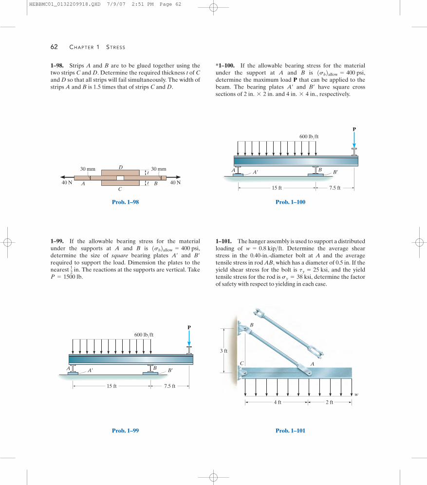
62 CHAPTER 1 STRESS
40 N40 N t
t
CA B
D30 mm 30 mm
Prob. 1–98
7.5 ft
P
A¿ B¿A B
600 lb/ft
15 ft
Prob. 1–99
7.5 ft
P
A¿ B¿A B
600 lb/ft
15 ft
1–98. Strips A and B are to be glued together using thetwo strips C and D. Determine the required thickness t of Cand D so that all strips will fail simultaneously. The width ofstrips A and B is 1.5 times that of strips C and D.
1–99. If the allowable bearing stress for the materialunder the supports at A and B is determine the size of square bearing plates and required to support the load. Dimension the plates to thenearest The reactions at the supports are vertical. TakeP = 1500 lb.
12
in.
B¿A¿
1sb2allow = 400 psi,1–101. The hanger assembly is used to support a distributedloading of Determine the average shearstress in the 0.40-in.-diameter bolt at A and the averagetensile stress in rod AB, which has a diameter of 0.5 in. If theyield shear stress for the bolt is and the yieldtensile stress for the rod is determine the factorof safety with respect to yielding in each case.
sy = 38 ksi,ty = 25 ksi,
w = 0.8 kip>ft.
4 ft 2 ft
3 ft
w
A
B
C
Prob. 1–101
*1–100. If the allowable bearing stress for the materialunder the support at A and B is determine the maximum load P that can be applied to thebeam. The bearing plates and have square crosssections of and respectively.4 in. * 4 in.,2 in. * 2 in.
B¿A¿
1sb2allow = 400 psi,
Prob. 1–100
HEBBMC01_0132209918.QXD 7/9/07 2:51 PM Page 62
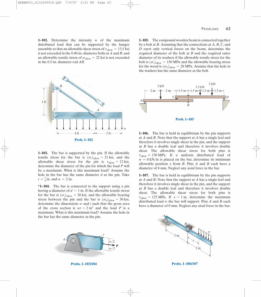
PROBLEMS 63
4 ft 2 ft
3 ft
w
A
B
C
P
t
w/2
w/2d
Probs. 1–103/104
1–105. The compound wooden beam is connected togetherby a bolt at B. Assuming that the connections at A, B, C, andD exert only vertical forces on the beam, determine therequired diameter of the bolt at B and the required outerdiameter of its washers if the allowable tensile stress for thebolt is and the allowable bearing stressfor the wood is Assume that the hole inthe washers has the same diameter as the bolt.
1sb2allow = 28 MPa.1st2allow = 150 MPa
1.5 m1.5 m1.5 m1.5 m2 m2 m
B
C DA
3 kN 1.5 kN2 kN
Prob. 1–105
1–103. The bar is supported by the pin. If the allowabletensile stress for the bar is and theallowable shear stress for the pin is determine the diameter of the pin for which the load P willbe a maximum. What is this maximum load? Assume thehole in the bar has the same diameter d as the pin. Take
and
*1–104. The bar is connected to the support using a pinhaving a diameter of If the allowable tensile stressfor the bar is and the allowable bearingstress between the pin and the bar is determine the dimensions and t such that the gross areaof the cross section is and the load P is amaximum. What is this maximum load? Assume the hole inthe bar has the same diameter as the pin.
wt = 2 in2w
1sb2allow = 30 ksi,1st2allow = 20 ksi,
d = 1 in.
w = 2 in.t =14
in.
tallow = 12 ksi,1st2allow = 21 ksi,
1–106. The bar is held in equilibrium by the pin supportsat A and B. Note that the support at A has a single leaf andtherefore it involves single shear in the pin, and the supportat B has a double leaf and therefore it involves doubleshear. The allowable shear stress for both pins is
If a uniform distributed load ofis placed on the bar, determine its minimum
allowable position x from B. Pins A and B each have adiameter of 8 mm. Neglect any axial force in the bar.
1–107. The bar is held in equilibrium by the pin supportsat A and B. Note that the support at A has a single leaf andtherefore it involves single shear in the pin, and the supportat B has a double leaf and therefore it involves doubleshear. The allowable shear stress for both pins is
If determine the maximumdistributed load the bar will support. Pins A and B eachhave a diameter of 8 mm. Neglect any axial force in the bar.
wx = 1 m,tallow = 125 MPa.
w = 8 kN>mtallow = 150 MPa.
A
2 m
x
B
w
2 m
Probs. 1–106/107
1–102. Determine the intensity of the maximumdistributed load that can be supported by the hangerassembly so that an allowable shear stress ofis not exceeded in the 0.40-in.-diameter bolts at A and B, andan allowable tensile stress of is not exceededin the 0.5-in.-diameter rod AB.
sallow = 22 ksi
tallow = 13.5 ksi
w
Prob. 1–102
HEBBMC01_0132209918.QXD 7/9/07 2:51 PM Page 63

64 CHAPTER 1 STRESS
1–109. The pin is subjected to double shear since it is usedto connect the three links together. Due to wear, the load isdistributed over the top and bottom of the pin as shown onthe free-body diagram. Determine the diameter d of the pinif the allowable shear stress is and the load
Also, determine the load intensities and w2 .w1P = 8 kip.tallow = 10 ksi
1–111. The cotter is used to hold the two rods together.Determine the smallest thickness t of the cotter and thesmallest diameter d of the rods. All parts are made of steelfor which the failure tensile stress is and thefailure shear stress is Use a factor of safetyof in tension and in shear.1F.S.2s = 1.751F.S.2t = 2.50
tfail = 375 MPa.sfail = 500 MPa
P
1 in.
d
1.5 in.
w2 w2
w1
P2
P2
1 in.
Prob. 1–109
P
1 in.
d
1.5 in.
w2 w2
w1
P2
P2
1 in.
30 kN
30 kN
10 mmt40 mm
d
d
Prob. 1–111
*1–108. The bar is held in equilibrium by the pin supportsat A and B. Note that the support at A has a single leaf andtherefore it involves single shear in the pin, and the supportat B has a double leaf and therefore it involves doubleshear. The allowable shear stress for both pins is
If and determinethe smallest required diameter of pins A and B. Neglect anyaxial force in the bar.
w = 12 kN>m,x = 1 mtallow = 125 MPa.
A
2 m
x
B
w
2 m
Prob. 1–108
1–110. The pin is subjected to double shear since it is usedto connect the three links together. Due to wear, the load isdistributed over the top and bottom of the pin as shown onthe free-body diagram. Determine the maximum load P theconnection can support if the allowable shear stress for the material is and the diameter of the pin is 0.5 in. Also, determine the load intensities and w2 .w1
tallow = 8 ksi
Prob. 1–110
HEBBMC01_0132209918.QXD 7/9/07 2:51 PM Page 64

CHAPTER REVIEW 65
The internal loadings in a body consistof a normal force, shear force, bendingmoment, and torsional moment. Theyrepresent the resultants of both a normaland shear stress distribution that actsover the cross section. To obtain theseresultants, use the method of sectionsand the equations of equilibrium.
If a bar is made from homogeneousisotropic material and it is subjected to aseries of external axial loads that passthrough the centroid of the cross section,then a uniform normal stress distributionwill act over the cross section. Thisaverage normal stress can be determinedfrom where P is the internalaxial load at the section.
s = P>A,
The average shear stress can bedetermined using where Vis the resultant shear force on the cross-sectional area A. This formula is oftenused to find the average shear stress infasteners or in parts used for connections.
tavg = V>A,
The design of any simple connectionrequires that the average stress alongany cross section not exceed a factor ofsafety or an allowable value of or
These values are reported in codesor standards and are considered safe onthe basis of experiments or throughexperience.
tallow .sallow F.S. =
sfail
sallow=
tfail
tallow
©Mz = 0
©My = 0
©Mx = 0
©Fz = 0
©Fy = 0
©Fx = 0
Chapter Review
O
F2F1
N
T
MV
TorsionalMoment
BendingMoment
ShearForce
FR
NormalForce
MRO
s
s s �
PP
P A
F
tavg �V A
s =
P
A
tavg =
V
A
HEBBMC01_0132209918.QXD 7/9/07 2:51 PM Page 65

66 CHAPTER 1 STRESS
1–114. Determine the resultant internal loadings actingon the cross sections located through points D and E of theframe.
1–115. The circular punch B exerts a force of 2 kN on thetop of the plate A. Determine the average shear stress inthe plate due to this loading.
1–113. The bearing pad consists of a 150 mm by 150 mmblock of aluminum that supports a compressive load of6 kN. Determine the average normal and shear stress actingon the plane through section a–a. Show the results on adifferential volume element located on the plane.
R E V I E W P R O B L E M S
*1–112. The long bolt passes through the 30-mm-thickplate. If the force in the bolt shank is 8 kN, determine theaverage normal stress in the shank, the average shear stressalong the cylindrical area of the plate defined by the sectionlines a–a, and the average shear stress in the bolt head alongthe cylindrical area defined by the section lines b–b.
8 kN18 mm
7 mm
30 mm
8 mm a
a
b
b
Prob. 1–112
30�
150 mm
6 kN
a
a
Prob. 1–113
2 kN
2 mm
B
A
4 mm
Prob. 1–115
4 ft
1.5 ftA
D
5 ft3 ftC
2.5 ft
E
B
150 lb/ft
Prob. 1–114
HEBBMC01_0132209918.QXD 7/9/07 2:51 PM Page 66

REVIEW PROBLEMS 67
1–117. The beam AB is pin supported at A and supportedby a cable BC. A separate cable CG is used to hold up theframe. If AB weighs 120 lb�ft and the column FC has aweight of 180 lb�ft, determine the resultant internalloadings acting on cross sections located at points D and E.Neglect the thickness of both the beam and column in thecalculation.
1–118. The 3-Mg concrete pipe is suspended by the threewires. If BD and CD have a diameter of 10 mm and AD hasa diameter of 7 mm, determine the average normal stress ineach wire.
*1–116. The cable has a specific weight ( )and cross-sectional area A. If the sag s is small, so that itslength is approximately L and its weight can be distributeduniformly along the horizontal axis, determine the averagenormal stress in the cable at its lowest point C.
weight>volumeg
1–119. The yoke-and-rod connection is subjected to atensile force of 5 kN. Determine the average normal stressin each rod and the average shear stress in the pin Abetween the members.
s
L/2 L/2
C
A B
Prob. 1–116
A
C
D
B
2 m
1 m
120�
120� 120�
Prob. 1–118
4 ft
12 ft
4 ft
8 ft12 ft
6 ft
A
E
G
B
F
D
C
Prob. 1–117
25 mm
40 mm
30 mm
A
5 kN
5 kN
Prob. 1–119
HEBBMC01_0132209918.QXD 7/9/07 2:51 PM Page 67

Horizontal ground displacement caused by an earthquake produced excessive strainin these bridge piers until they fractured. By making measurements of strain, engineerscan then obtain the stress in the material.
HEBBMC02_0132209918.QXD 7/14/07 11:56 AM Page 68

2 Strain
CHAPTER OBJECTIVES
In engineering the deformation of a body is specified using the concept ofnormal and shear strain. In this chapter we will define these quantities andshow how they can be determined for various types of problems.
2.1 Deformation
Whenever a force is applied to a body, it will tend to change the body’sshape and size. These changes are referred to as deformation, and theymay be either highly visible or practically unnoticeable, without the useof equipment to make precise measurements. For example, a rubberband will undergo a very large deformation when stretched. On theother hand, only slight deformations of structural members occur when abuilding is occupied with people walking about. Deformation of a bodycan also occur when the temperature of the body is changed. A typicalexample is the thermal expansion or contraction of a roof caused by theweather.
69
HEBBMC02_0132209918.QXD 7/4/07 12:11 PM Page 69
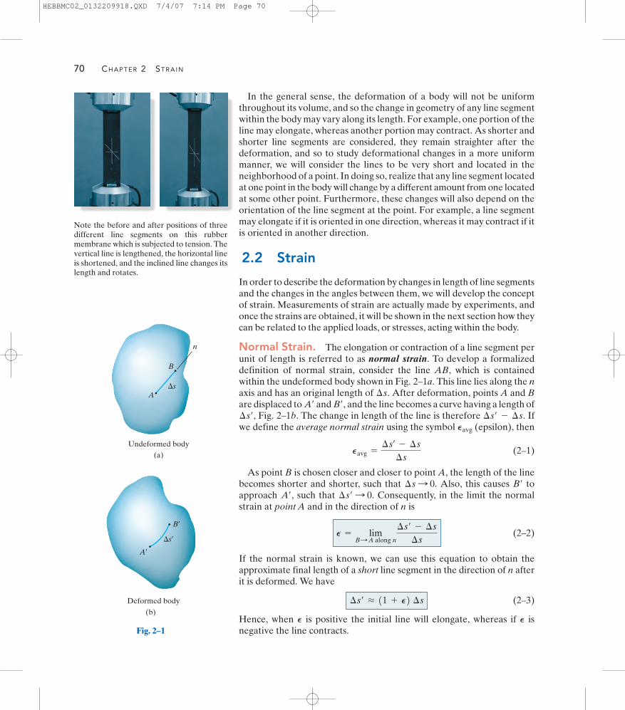
70 CHAPTER 2 STRAIN
In the general sense, the deformation of a body will not be uniformthroughout its volume, and so the change in geometry of any line segmentwithin the body may vary along its length. For example, one portion of theline may elongate, whereas another portion may contract. As shorter andshorter line segments are considered, they remain straighter after thedeformation, and so to study deformational changes in a more uniformmanner, we will consider the lines to be very short and located in theneighborhood of a point. In doing so, realize that any line segment locatedat one point in the body will change by a different amount from one locatedat some other point. Furthermore, these changes will also depend on theorientation of the line segment at the point. For example, a line segmentmay elongate if it is oriented in one direction, whereas it may contract if itis oriented in another direction.
2.2 Strain
In order to describe the deformation by changes in length of line segmentsand the changes in the angles between them, we will develop the conceptof strain. Measurements of strain are actually made by experiments, andonce the strains are obtained, it will be shown in the next section how theycan be related to the applied loads, or stresses, acting within the body.
Normal Strain. The elongation or contraction of a line segment perunit of length is referred to as normal strain. To develop a formalizeddefinition of normal strain, consider the line AB, which is containedwithin the undeformed body shown in Fig. 2–1a. This line lies along the naxis and has an original length of After deformation, points A and Bare displaced to and and the line becomes a curve having a length of
Fig. 2–1b. The change in length of the line is therefore Ifwe define the average normal strain using the symbol (epsilon), then
(2–1)
As point B is chosen closer and closer to point A, the length of the linebecomes shorter and shorter, such that Also, this causes toapproach such that Consequently, in the limit the normalstrain at point A and in the direction of n is
(2–2)
If the normal strain is known, we can use this equation to obtain theapproximate final length of a short line segment in the direction of n afterit is deformed. We have
(2–3)
Hence, when is positive the initial line will elongate, whereas if isnegative the line contracts.
PP
¢s¿ L 11 + P2 ¢s
P = limB:A along n
¢s¿ - ¢s
¢s
¢s¿ : 0.A¿,B¿¢s : 0.
Pavg =
¢sœ
- ¢s
¢s
Pavg
¢s¿ - ¢s.¢s¿,B¿,A¿
¢s.
Note the before and after positions of threedifferent line segments on this rubbermembrane which is subjected to tension. Thevertical line is lengthened, the horizontal lineis shortened, and the inclined line changes itslength and rotates.
Undeformed body
n
�sA
B
(a)
Deformed body
A¿
B¿
�s¿
(b)
Fig. 2–1
HEBBMC02_0132209918.QXD 7/4/07 7:14 PM Page 70

SECTION 2.2 STRAIN 71
Units. Note that normal strain is a dimensionless quantity, since it isa ratio of two lengths. Although this is the case, it is common practiceto state it in terms of a ratio of length units. If the SI system is used,then the basic units will be . Ordinarily, for mostengineering applications will be very small, so measurements of strainare in micrometers per meter where In theFoot-Pound-Second system, strain can be stated in units of inches perinch ( ). Sometimes for experimental work, strain is expressed as apercent, e.g., As an example, a normal strain of
can be reported as , or 0.0480%.Also, one can state this answer as simply (480 “micros”).
Shear Strain. The change in angle that occurs between two linesegments that were originally perpendicular to one another is referred toas shear strain. This angle is denoted by (gamma) and is measured inradians (rad). To show how it is developed, consider the line segmentsAB and AC originating from the same point A in a body, and directedalong the perpendicular n and t axes, Fig. 2–2a. After deformation, theends of the lines are displaced, and the lines themselves become curves,such that the angle between them at A is Fig. 2–2b. Hence we definethe shear strain at point A that is associated with the n and t axes as
(2–4)
Notice that if is smaller than the shear strain is positive, whereas ifis larger than the shear strain is negative.p>2u¿
p>2u¿
gnt =
p
2-
lim u¿B : A along nC : A along t
u¿,
g
480 m480 mm>m,in.>in.480110-62480110-62 0.001 m>m = 0.1%.
in.>in.
1 mm = 10-6 m.1mm>m2,P
meters>meter (m>m)
Undeformed body
n t
A
BC
(a)
p 2
Fig. 2–2
Deformed body
B¿
A¿
C ¿
(b)
u¿
HEBBMC02_0132209918.QXD 7/4/07 7:15 PM Page 71

72 CHAPTER 2 STRAIN
Cartesian Strain Components. Using the above definitions ofnormal and shear strain, we will now show how they can be used todescribe the deformation of the body, Fig. 2–3a. To do so, imagine thebody to be subdivided into small elements such as the one shown in Fig. 2–3b. This element is rectangular, has undeformed dimensions
and and is located in the neighborhood of a point in the body,Fig. 2–3a. Assuming that the element’s dimensions are very small,the deformed shape of the element will be a parallelepiped, Fig. 2–3c,since very small line segments will remain approximately straight afterthe body is deformed. In order to achieve this deformed shape, we mustfirst consider how the normal strain changes the lengths of the sides ofthe rectangular element, and then how the shear strain changes theangles of each side. Hence, using Eq. 2–3, inreference to the lines and the approximate lengths of thesides of the parallelepiped are
And the approximate angles between the sides, again originally definedby the sides and are
In particular, notice that the normal strains cause a change in volumeof the rectangular element, whereas the shear strains cause a change inits shape. Of course, both of these effects occur simultaneously duringthe deformation.
In summary, then, the state of strain at a point in a body requiresspecifying three normal strains, and three shear strains,
These strains completely describe the deformation of arectangular volume element of material located at the point and orientedso that its sides are originally parallel to the x, y, z axes. Once thesestrains are defined at all points in the body, the deformed shape of thebody can then be described. It should also be added that by knowingthe state of strain at a point, defined by its six components, it is possible todetermine the strain components on an element oriented at the point inany other direction. This is discussed in Chapter 10.
gxz .gyz ,gxy ,Pz ,Py ,Px ,
p
2- gxy p
2- gyz p
2- gxz
¢z,¢y,¢x,
11 + Px2 ¢x 11 + Py2 ¢y 11 + Pz2 ¢z
¢z,¢y,¢x,¢s¿ L 11 + P2 ¢s,
¢z,¢y,¢x,
(a)
y
x
z
Fig. 2–3
(b)
�y�x
�z
Undeformedelement
p 2
p 2
p 2
(1 � �y)�y(1 � �x)�x
(1 � �z)�z
Deformedelement
(
(c)
� gyz)
( � gxz)
( � gxy)p 2
p 2
p 2
HEBBMC02_0132209918.QXD 7/9/07 2:58 PM Page 72

SECTION 2.2 STRAIN 73
Small Strain Analysis. Most engineering design involves applicationsfor which only small deformations are allowed. For example, almost allstructures and machines appear to be rigid, and the deformations thatoccur during use are hardly noticeable. Furthermore, even if the deflectionof a member such as a thin plate or slender rod may appear to be large,the material from which it is made may only be subjected to very smalldeformations. In this text, therefore, we will assume that the deformationsthat take place within a body are almost infinitesimal, so that the normalstrains occurring within the material are very small compared to 1, that is,
This assumption, which is based on the magnitude of the strain,has wide practical application in engineering, and it is often referred to asa small strain analysis. For example, it allows us to approximate
and provided is very small.utan u = ucos u = 1sin u = u,
P V 1.
Important Points
• Loads will cause all material bodies to deform and, as a result,points in the body will undergo displacements or changes inposition.
• Normal strain is a measure of the elongation or contraction of asmall line segment in the body, whereas shear strain is a measureof the change in angle that occurs between two small line segmentsthat are originally perpendicular to one another.
• The state of strain at a point is characterized by six straincomponents: three normal strains and three shearstrains These components depend upon theorientation of the line segments and their location in the body.
• Strain is the geometrical quantity that is measured usingexperimental techniques. Once obtained, the stress in the bodycan then be determined from material property relations.
• Most engineering materials undergo small deformations,and so thenormal strain This assumption of “small strain analysis”allows the calculations for normal strain to be simplified since first-order approximations can be made about their size.
P V 1.
gxz .gyz ,gxy ,PzPy ,Px ,
The rubber bearing support under thisconcrete bridge girder is subjected to bothnormal and shear strain. The normal strain iscaused by the weight and bridge loads on thegirder, and the shear strain is caused by thehorizontal movement of the girder due totemperature changes.
HEBBMC02_0132209918.QXD 7/4/07 12:12 PM Page 73
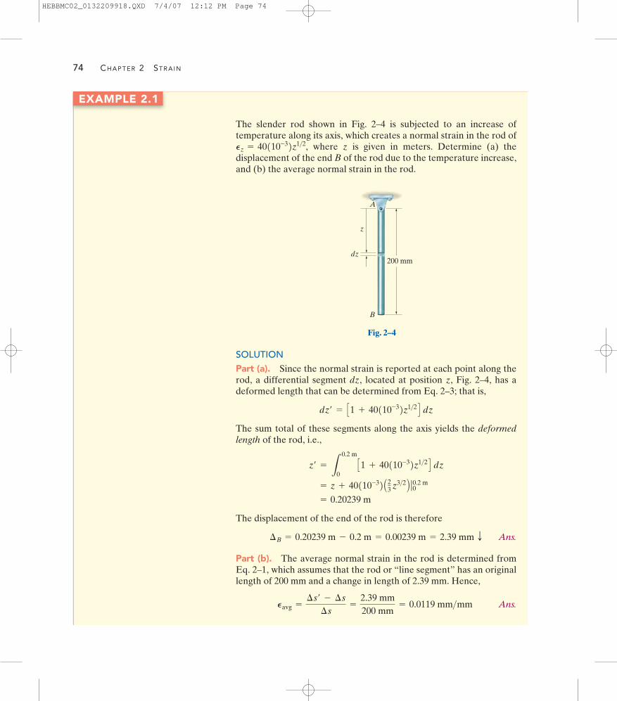
74 CHAPTER 2 STRAIN
EXAMPLE 2.1
The slender rod shown in Fig. 2–4 is subjected to an increase oftemperature along its axis, which creates a normal strain in the rod of
where z is given in meters. Determine (a) thedisplacement of the end B of the rod due to the temperature increase,and (b) the average normal strain in the rod.
Pz = 40110-32z1>2,
SOLUTIONPart (a). Since the normal strain is reported at each point along therod, a differential segment dz, located at position z, Fig. 2–4, has adeformed length that can be determined from Eq. 2–3; that is,
The sum total of these segments along the axis yields the deformedlength of the rod, i.e.,
The displacement of the end of the rod is therefore
Ans.
Part (b). The average normal strain in the rod is determined fromEq. 2–1, which assumes that the rod or “line segment” has an originallength of 200 mm and a change in length of 2.39 mm. Hence,
Ans.Pavg =
¢s¿ - ¢s
¢s=
2.39 mm200 mm
= 0.0119 mm>mm
¢B = 0.20239 m - 0.2 m = 0.00239 m = 2.39 mm T
= 0.20239 m
= z + 40110-32A23 z3>2 B ƒ00.2 m
z¿ =
L
0.2 m
0C1 + 40110-32z1>2 D dz
dz¿ = C1 + 40110-32z1>2 D dz
200 mm
A
z
dz
B
Fig. 2–4
HEBBMC02_0132209918.QXD 7/4/07 12:12 PM Page 74

SECTION 2.2 STRAIN 75
EXAMPLE 2.2
A force acting on the grip of the lever arm shown in Fig. 2–5a causesthe arm to rotate clockwise through an angle of Determine the average normal strain developed in the wire BC.
u = 0.002 rad.
A
BC
(a)
1 m
0.5 m
1 m
0.5 m
A
B
u
B¿C
(b)
Fig. 2–5
SOLUTIONSince is small, the stretch in the wire CB, Fig. 2–5b, is The average normalstrain in the wire is therefore,
Ans.Pavg =
BB¿
CB=
0.001 m1 m
= 0.001 m>m
BB¿ = u10.5 m2 = 10.002 rad210.5 m2 = 0.001 m.u = 0.002 rad
HEBBMC02_0132209918.QXD 7/4/07 12:12 PM Page 75

76 CHAPTER 2 STRAIN
EXAMPLE 2.3
The plate is deformed into the dashed shape shown in Fig. 2–6a. If inthis deformed shape horizontal lines on the plate remain horizontaland do not change their length, determine (a) the average normalstrain along the side AB, and (b) the average shear strain in the platerelative to the x and y axes.
300 mm
(a)
CA
B
y
x
250 mm
3 mm
2 mm
Fig. 2–6
(b)
A
B
250 mm
3 mm
2 mmB¿
SOLUTIONPart (a). Line AB, coincident with the y axis, becomes line after deformation, as shown in Fig. 2–6b. The length of this line is
The average normal strain for AB is therefore
Ans.
The negative sign indicates the strain causes a contraction of AB.
Part (b). As noted in Fig. 2–6c, the once 90° angle BAC between thesides of the plate, referenced from the x, y axes, changes to due tothe displacement of B to Since then is theangle shown in the figure. Thus,
Ans.gxy = tan-1 a 3 mm250 mm - 2 mm
b = 0.0121 rad
gxygxy = p>2 - u¿,B¿.u¿
= -7.93110-32 mm>mm
1PAB2avg =
AB¿ - AB
AB=
248.018 mm - 250 mm250 mm
AB¿ = 21250 - 222 + 1322 = 248.018 mm
AB¿
(c)
CA
u¿
gxy
B
y
x
250 mm
3 mm2 mm
B¿
HEBBMC02_0132209918.QXD 7/4/07 12:12 PM Page 76

SECTION 2.2 STRAIN 77
EXAMPLE 2.4
The plate shown in Fig. 2–7a is fixed connected along AB and held inthe rigid horizontal guides at its top and bottom, AD and BC. If itsright side CD is given a uniform horizontal displacement of 2 mm,determine (a) the average normal strain along the diagonal AC, and(b) the shear strain at E relative to the x, y axes.
SOLUTIONPart (a). When the plate is deformed, the diagonal AC becomesFig. 2–7b. The length of diagonals AC and can be found from thePythagorean theorem. We have
Therefore the average normal strain along the diagonal is
Ans.
Part (b). To find the shear strain at E relative to the x and y axes, it isfirst necessary to find the angle which specifies the angle betweenthese axes after deformation, Fig. 2–7b. We have
Applying Eq. 2–4, the shear strain at E is therefore
Ans.
According to the sign convention, the negative sign indicates that theangle is greater than 90°.
NOTE: If the x and y axes were horizontal and vertical at point E,then there would be no normal strain in the y direction and a normalstrain in the x direction. The axes would remain perpendicular to oneanother, and so due to the deformation, at point E.gxy = 0
u¿
gxy =
p
2- 1.58404 rad = -0.0132 rad
u¿ = 90.759° =
p
180° 190.759°2 = 1.58404 rad
tan a u¿2b =
76 mm75 mm
u¿,
= 0.00669 mm>mm
1PAC2avg =
AC¿ - AC
AC=
0.21355 m - 0.21213 m0.21213 m
AC¿ = 210.15022 + 10.15222 = 0.21355 m
AC = 210.15022 + 10.15022 = 0.21213 m
AC¿
AC¿, 150 mm
(a)
2 mm
y
150 mm
x
D
B C
A
E
Fig. 2–7
76 mm
(b)
75 mm
E¿
D¿
B C¿
A
75 mm
76 mm
u¿
HEBBMC02_0132209918.QXD 7/4/07 12:12 PM Page 77

78 CHAPTER 2 STRAIN
P R O B L E M S
2–1. An air-filled rubber ball has a diameter of 6 in. If theair pressure within it is increased until the ball’s diameterbecomes 7 in., determine the average normal strain in therubber.
2–2. A thin strip of rubber has an unstretched length of 15 in. If it is stretched around a pipe having an outerdiameter of 5 in., determine the average normal strain inthe strip.
2–3. The rigid beam is supported by a pin at A and wiresBD and CE. If the load P on the beam causes the end C tobe displaced 10 mm downward, determine the normalstrain developed in wires CE and BD.
*2–4. The center portion of the rubber balloon has adiameter of If the air pressure within it causesthe balloon’s diameter to become determine theaverage normal strain in the rubber.
d = 5 in.,d = 4 in.
C
3 m
ED
2 m
4 m
P
BA
2 m
Prob. 2–3
d
Prob. 2–4
2–5. The rigid beam is supported by a pin at A and wiresBD and CE. If the load P on the beam is displaced 10 mmdownward, determine the normal strain developed in wiresCE and BD.
2–6. The rigid beam is supported by a pin at A and wiresBD and CE. If the maximum allowable normal strain ineach wire is determine the maximumvertical displacement of the load P.
Pmax = 0.002 mm>mm,
A CB
3 m 2 m 2 m
3 m4 m
P
D
E
Probs. 2–5/6
2–7. The two wires are connected together at A. If theforce P causes point A to be displaced horizontally 2 mm,determine the normal strain developed in each wire.
P30�
30� A
B
C
300 mm
300 mm
Prob. 2–7
HEBBMC02_0132209918.QXD 7/4/07 12:12 PM Page 78

L
AC
L
B
L
u
PROBLEMS 79
*2–8. Part of a control linkage for an airplane consists ofa rigid member CBD and a flexible cable AB. If a forceis applied to the end D of the member and causes it torotate by determine the normal strain in the cable.Originally the cable is unstretched.
2–9. Part of a control linkage for an airplane consists ofa rigid member CBD and a flexible cable AB. If a force isapplied to the end D of the member and causes a normalstrain in the cable of , determine thedisplacement of point D. Originally the cable is unstretched.
0.0035 mm>mm
u = 0.3°,
*2–12. The piece of plastic is originally rectangular.Determine the shear strain at corners A and B if theplastic distorts as shown by the dashed lines.
2–13. The piece of plastic is originally rectangular.Determine the shear strain at corners D and C if theplastic distorts as shown by the dashed lines.
2–14. The piece of plastic is originally rectangular.Determine the average normal strain that occurs along thediagonals AC and DB.
gxy
gxy
400 mm
300 mm
A
B
D P
300 mm
C
u
Probs. 2–8/9
2–10. The wire AB is unstretched when If avertical load is applied to bar AC, which causes determine the normal strain in the wire.
2–11. If a load applied to bar AC causes point A to bedisplaced to the left by an amount determine thenormal strain in wire AB. Originally, u = 45°.
¢L,
u = 47°,u = 45°.
Probs. 2–10/11
300 mm
400 mmD A
y
x
3 mm
2 mm
B
5 mm
2 mm4 mm
2 mm
C
Probs. 2–12/13/14
2–15. The guy wire AB of a building frame is originallyunstretched. Due to an earthquake, the two columns of theframe tilt Determine the approximate normal strainin the wire when the frame is in this position. Assume thecolumns are rigid and rotate about their lower supports.
u = 2°.
B
A
1 m
3 m
4 m
u � 2� u � 2�
Prob. 2–15
HEBBMC02_0132209918.QXD 7/4/07 12:12 PM Page 79

80 CHAPTER 2 STRAIN
2–18. The square deforms into the position shown by thedashed lines. Determine the average normal strain alongeach diagonal, AB and CD. Side remains horizontal.D¿B¿
*2–20. The block is deformed into the position shown bythe dashed lines. Determine the average normal strain alongline AB.
*2–16. The corners of the square plate are given thedisplacements indicated. Determine the shear strain alongthe edges of the plate at A and B.
2–17. The corners of the square plate are given thedisplacements indicated. Determine the average normalstrains along side AB and diagonals AC and DB.
2–19. The square deforms into the position shown by thedashed lines. Determine the shear strain at each of itscorners, A, B, C, and D. Side remains horizontal.D¿B¿
0.3 in.
0.2 in.
0.3 in.
10 in.10 in.
10 in.
10 in.
0.2 in.
y
x
A
B
C
D
Probs. 2–16/17
A
50 mm8 mm
50 mm
3 mm
53 mm
D
y
x
D¿B
CC¿
B¿
91.5�
Prob. 2–18
A
50 mm8 mm
50 mm
3 mm
D
y
x
B
CC¿
B¿
91.5�
53 mm
D¿
Prob. 2–19
y
x
BB¿
70 mm
70 mm55 mm
100 mm
30 mm
30 mm30 mm
110 mm
15 mm
A
Prob. 2–20
HEBBMC02_0132209918.QXD 7/4/07 12:12 PM Page 80

PROBLEMS 81
2–22. The rectangular plate is subjected to the deformationshown by the dashed line. Determine the average shearstrain of the plate.gxy
2–25. The piece of rubber is originally rectangular.Determine the average shear strain if the corners B andD are subjected to the displacements that cause the rubberto distort as shown by the dashed lines.
2–26. The piece of rubber is originally rectangular andsubjected to the deformation shown by the dashed lines.Determine the average normal strain along the diagonalDB and side AD.
gxy
2–21. A thin wire, lying along the x axis, is strained suchthat each point on the wire is displaced along thex axis. If k is constant, what is the normal strain at any pointP along the wire?
¢x = kx22–23. The rectangular plate is subjected to the deformationshown by the dashed lines. Determine the average shearstrain of the plate.
*2–24. The rectangular plate is subjected to the deformationshown by the dashed lines. Determine the average normalstrains along the diagonal AC and side AB.
gxy
x
Px
Prob. 2–21
3 mm
3 mm150 mm
y
x
200 mm
x¿
y¿
B
A
Prob. 2–22
3 mm 3 mm
150 mm
y
x
B C
A D
200 mm
Probs. 2–23/24
300 mm
400 mm
D
A
y
x
3 mm
2 mmB
C
Probs. 2–25/26
HEBBMC02_0132209918.QXD 7/4/07 12:12 PM Page 81

82 CHAPTER 2 STRAIN
2–29. The block is deformed into the position shown bythe dashed lines. Determine the shear strain at corners Cand D.
2–31. The curved pipe has an original radius of 2 ft. If it isheated nonuniformly, so that the normal strain along itslength is determine the increase in length ofthe pipe.
*2–32. Solve Prob. 2–31 if P = 0.08 sin u.
P = 0.05 cos u,
2–27. The material distorts into the dashed positionshown. Determine (a) the average normal strains andthe shear strain at A, and (b) the average normal strainalong line BE.
*2–28. The material distorts into the dashed positionshown. Determine the average normal strain that occursalong the diagonals AD and CF.
gxy
PyPx ,2–30. The bar is originally 300 mm long when it is flat. If itis subjected to a shear strain defined by wherex is in millimeters, determine the displacement at theend of its bottom edge. It is distorted into the shape shown,where no elongation of the bar occurs in the x direction.
¢ygxy = 0.02x,
x
y
80 mm
50 mm
25 mm
100 mm
15 mm10 mmD
E
FA
B
C
Probs. 2–27/28
y
Dx C
100 mm
85 mm
100 mm110 mm
15 mm
Prob. 2–29
300 mm
�y
x
y
Prob. 2–30
2 ft
Au
Probs. 2–31/32
HEBBMC02_0132209918.QXD 7/4/07 12:12 PM Page 82

PROBLEMS 83
2–35. If the normal strain is defined in reference to thefinal length, that is,
instead of in reference to the original length, Eq. 2–2, showthat the difference in these strains is represented as asecond-order term, namely, Pn - Pn
œ
= PnPnœ .
Pnœ
= limp:p¿
a¢s¿ - ¢s
¢s¿
b
2–34. The fiber AB has a length L and orientation If itsends A and B undergo very small displacements and respectively, determine the normal strain in the fiber whenit is in position A¿B¿.
vB ,uA
u.2–33. A thin wire is wrapped along a surface having theform where x and y are in inches. Originallythe end B is at If the wire undergoes a normalstrain along its length of determine the changein length of the wire. Hint: For the curve, ds = 21 + 1dy>dx22 dx.
y = f1x2,P = 0.005x,
x = 10 in.y = 0.5x2,
y
y � 0.5x2
xx
B
A
A
y
x
B ¿
BvB
uA A¿
Lu
Prob. 2–34
Prob. 2–33
HEBBMC02_0132209918.QXD 7/4/07 12:12 PM Page 83