the british industries fair. - politechnika...
TRANSCRIPT

V o l . X II. OCTOBER, 1931. No. 133.
A Good Exhibition.
The Coal Face Machinery Exhibition was in every way successful. All the essential features which make for success in any trade exhibition were present in full measure : the place was right, the management was expert, the visitors were of the right kind—and, by no means less important, the salesmen on the stands were also of the right kind. We have no actual figures but do not think it would be very wide of the mark to estimate that some eight thousand visitors handed their tickets to the commissionaire at the door. The tickets represented personal invitations and, in consequence, it was the animated collective voice of a serious business crowd which evened out the clattersome rattle of working exhibits. There were coalcutter men, working miners and engineers mingling with their owners and managers : technical students and apprentices were accompanied by professors and teachers. They came in units and attenuated small parties from adjacent pit districts, and they came as compact regiments by excursions from remote South Wales and the far North. These men were keen to learn and to buy.
Equally effective for the pursuance of business was the personnel at the stands of the exhibitors : proprietors and managing directors backed up their sales managers and representatives—and in all cases the erecting fitters, journeymen mechanics and electricians, the men who in the mines regularly installed and worked with the machinery, were there in goodly numbers to demonstrate the merits of the plant and to drive home the selling points by force of the word and example most understandable to the potential buyer and user. Which conditions were all just as they should be at a trade exhibition but which, unfortunately, are often not much in evidence.
What a great change has come over this country all in a few short weeks. Here is now, as it were, a live feeling of exhilaration after the rude shaking which at long last had to awaken the nation from wasting torpor. Clear now is the national view of needs and opportunities ; and all around there is a kindling of the old determination to make profit out of sacrifice. Trade, industry, money—all these are names for the same thing, the material which builds and sustains nations and empires. It would not be stretching things too far to attribute the success of the Sheffield exhibition in some measure to this reawakening of the public mind. Be _ that as it may, there is no doubt as to the mining industry now being thoroughly on the alert for
business, and ready and willing to launch out with modern equipments. The exhibition proved conclusively that the time has arrived when makers of mining plant can engage in an aggressive and whole-hearted sales campaign with the assurance of success.
In this connection it is to be noted that the Sheffield exhibition was purely a “ home trade ” affair. True, there were several examples of coal face machinery of Continental ancf American origin to be seen amongst the exhibits. They served to impress at least one fairly obvious useful lesson—and the side-by-side comparison of the British article with the foreign was, well, quite reassuring. But the show was one for home “ buyers” : and the newspapers during the time of the exhibition were each morning drumming the alarms of the huge difference in the values of British exports and imports 1 Naturally, the greater the development in the equipment and production resources of our collieries and works generally, the greater is the national scope for increased export trade.
We know that, in respect of design, workmanship and performance, British mechanical and electrical mining plant is in general superior to that made in any other country ; one of the real advantages which can without argument be credited to the oft-considered irksome yoke of rigid safety legislation. British winding gears, coalcutters, switchgear and cables have for years past found their way to mining places abroad, and it is clear that the development of the export of just such specialist products is one of the surest ways in which this country can best hope to correct the national “ balance of trade.”
The British Industries Fair.So it would appear that the present need for
an “ export trade ” exhibition is clearly indicated and that the national political and economic circumstances as well as the temperament of the people are auspiciously attuned to the certainty of success. Progressive firms will therefore turn their serious attention to the business potentialities of the British Industries Fair and carefully weigh the advantages which it offers for swelling the overseas trade in their particular line of goods or class of product. Each succeeding year has seen the Fair rapidly advance both in regard to site area and the range of exhibits ; it has definitely become one of the greatest international fairs in the calendar of the world’s commerce. Whilst always conceding that the fairs of past years were wonderfully organised and successful, we have been disappointed with the comparatively meagre representation of mining and electrical

118 THE MINING ELECTRICAL ENGINEER. October, 1931.
equipments and appliances, the manufacture of which constitutes a great industry in which this country with its vast colliery and mining interests stands pre-eminent above all others.
The management of the Fair are this year making an exceptionally strong appeal for this class of support. They offer a remarkably convincing series of services and facilities ; they ensure that the right visitors from overseas will be brought in ; that the transport, handling and display of exhibits shall be as convenient, economical and effective as is possible. In short, the well tried and proved organisation of the fair is to concentrate particularly on making the mining, colliery and quarrying machinery and equipment section a notable innovation of the next Fair.
The Strength of the A.M.E.E.
This month the Association of Mining Electrical Engineers resumes its sessional meetings and the date is appropriate for a brief reference to the extensive field so usefully and effectively covered by the deliberations of the two thousand or more members associated with seventeen branches. Every branch has an organised programme for regular monthly meetings from now on until the return of Spring. This means that spread over the whole of the colliery areas of Great Britain there will be about 120 opportunities for mining electrical men to get together for the purpose of hearing papers and lectures, debating problems, comparing experiences, visiting notable places, and in many other ways passing some of the recreative hours in each others’ company with profit and pleasure.
Large and representative as is the present list of members it does not by any means include the names of all those who are eligible. ’ There are
The Lighting of Mines.(Abstract from the Annual Report o f II.M Chief Inspector o f Mines, 1930)
Of recent years there has been a steadily growing recognition in the mining industry of the importance of improved lighting as a means to greater health and
safety and to increased efficiency generally ; and it is hardly too much to say that greatly improved lighting is coming to be regarded as an essential adjunct to modern methods of intensive mining.
While notable advances have been made at individual collieries, these collieries are as yet comparatively few in number and the movement is slow in spreading through the industry as a whole. With the object of focussing attention on the matter and securing a measure of general improvement throughout the industry, it was decided towards the end of 1930 to draw up and circulate Departmental proposals which would
serve as a basis of discussion for dealing with the matter by General Regulations. These proposals have been widely and usefully discussed within the industry and by the Department with representatives of the industry and the many manufacturing interests concerned.
Their effect is, briefly, as follows:—
(1) To fix a higher candle-power standard for new safety lamps (both flame and electric) submitted for approval;
(2) To require that the lighting efficiency of safety shall be adequately maintained in the colliery
still many engineering men who are denying themselves one of the most pleasant and least expensive means to the “ better job ”. W ill those men consider with an open mind what the Association gives to each of its members for one guinea a year ?
We do not propose to dwell upon the invaluable aid which the A.M.E.E. during its twenty- two years has rendered in advancing the status of electrical mines workers, nor the eminently high prestige and reputation which the Association has attained in authoritative and official circles in this country and abroad. We merely mention these matters to give point to the statement that there is much more to be done, and that the Association blessed with the vigour of healthy maturity is destined to take up and be entrusted with in creasingly greater and more responsible duties in pressing forward the general advance of the British mining industry.
Glasgow : 1932.At the recent meeting of the Council of the
Association of Mining Electrical Engineers the members were delighted to accept the cordial invitation of the West of Scotland Branch to hold the next Annual General Meeting and Convention in Glasgow. Those who were so fortunate as to take part in the last Scottish A.M.E.E. Festival, for only so can it adequately be named in happy recollection, will thi’ough the dismal months ahead find hope strengthened in the anticipation of another glorious week in June. Maybe the members who missed the 1923 Convention would like to refer back to our issue of July that year ; it would give them a little idea of the good days in prospect and might perchance induce them to indulge in a few moments making pleasant plans for next Summer.
lamp rooms up to certain fixed candle-power standards. (These standards, of course, to allow for normal deterioration, would necessarily be lower than the corres
ponding standards for new lamps.)
(3) Broadly speaking, the existing General Regulations prohibit the use in safety lamp mines, within 300 yards of the face, of any form of lighting other than the approved safety lamp. It is proposed to allow some relaxation of this general prohibition by taking powers to permit electric and other forms of lighting in any part of a mine where the conditions are suitable and where safety can be ensured by the provision of suitable and well protected equipment. (Such permissions would not be general but would be based on detailed investigation of particular proposals and limited to particular mines and or particular apparatus.)
(4) Experience has shewn that the lighting of roadways is greatly improved if the stone-dusting (which is compulsory as a precaution against coal dust explosion) is done with white or light-coloured dust; and it is proposed that this should be made general.
(5) The advantages of whitewashing are being increasingly recognised and applied and it is proposed that whitewashing should be done generally at pit bottoms and landings, on the haulage roads at junctions, pass-byes and other places where persons are regularly at work, and in engine rooms and motor rooms.
(6) Finally it is proposed to require sufficient and suitable lighting for all work above ground.

October, 1931. THE MINING ELECTRICAL ENGINEER. 119
STARTERS FOR SQUIRREL-CAGE
MOTORS.
A. V. L A W R Y .
In view of the very wide application, in these days, of squirrel-cage induction motors, a clear statement of the initial starting torque and current consequent upon the use of the various conventional forms of squirrel- cage motor starters may be of service to many engineers. In the following notes the breakaway torque and the initial starting current are referred to as a percentage of the torque developed and current taken by a motor at standstill with full voltage applied ; i.e. short circuit torque and current, respectively. The actual values which will be obtained in practice with any particular machine can then be easily obtained from a knowledge of its short circuit characteristics. Typical figures are
Type Motor.
Standard ..............High Starting Torque
Stand Still Torque X.
F.L.12
Short Circuit Current X.
F.L.64*
There are four types of starter by which these machines are normally controlled, namely :
(a) Direct.
(b) Star Delta (three-phase).Series Parallel (two-phase).
(c) Auto Transformer,
(d) Stator Resistance.
Direct.
(a) With a direct starter (which obviously is the simplest type from a switching point of view) the motor will develop its maximum breakaway torque. The current at the instant of switching on, however, is also the most that the machine can take and hence its use is somewhat restricted by supply authorities’ regulations. This method is chiefly used for small motors and when a heavy load
has to be accelerated
Star Delta.
(b) Star Delta starting is the most commonly used of the various methods available. The six terminals of the motor winding mlist be brought out. The starter has three positions—“ off ” , “ start” (Star), “ R un” (Delta). A correct sequence device is normally incorporated thus preventing the possibility of the handle being switched into delta before going into star. The voltage impressed upon each motor winding in the star position is K3 of the full line pressure. Since the torque
developed by the machine at standstill varies as the square of the voltage applied to its windings the motor at the instant of switching on develops 33!°/° of its short circuit torque. A system of impedances connected in the star has three times the impedance of the same system connected in delta hence the current taken in the start position will be $ of the short circuit current. Thus, star delta switching substantially reduces both the standstill torque and current, and in view of this latter fact is acceptablc to supply authorities for much larger horse powers than is direct starting. A typical connection diagram of the star-delta method is shewn in Fig. 1.
Series Parallel.
The series parallel type of starter is really the two- phase counterpart of the three-phase star delta equipment. The motor must have eight terminals, each of the two windings of the machine being divided into two
parts. In the start position the two halves of each winding are connected in series (each winding being connected across its supply phase) while in the run position the two halves are connected in parallel instead of in series.
In this case, in the start position half voltage is applied to each phase winding, the torque at standstill consequently being jth of the short circuit figure while the current is Jth of the short circuit value. Hence both torque and current are slightly less than with a three- phase star delta starter.
Auto Transformer.
(c) Auto transformer starters are quite common, though less so than they were before the advent of the high starting torque squirrel cage motor with its lower short circuit current. The scheme ordinarily is to use a change over switch (again with correct sequence device) and an auto transformer having tappings, usually to give 40%, 60o/o, and 75°/o of full line voltage. In the “ start” position the motor is connected to one of the low voltage tappings. When the motor is up to speed the starter handle is thrown into “ run ” , thus cutting out the transformer and connecting full voltage on the machine. The following standstill torques and currents are obtained :
Tap Torque (°/o short Line Current {“fa short(Vo full volts) circuit torque) circuit current)
40 16 1660 36 3675 56 56
The figures in the middle column are obtained bearing in mind that the torque varies as the square of the voltage. In regard to the third column, take the 40% tap as an example. The current taken by the motor will be 40°/o of the short circuit value. The current drawn from the line will be less than the amount taken by the machine owing to the auto transformer ratio of
40 X 40transformation. In the present case. ------ = 16°/».
100
The line current is, in fact, the short circuit current multiplied by the square of the percentage tap.
Fig. 1.—Connections of Star Delta Starter.
Start connects C2 to 1, /i2 to 2, A2 to 3, H\ to A\ to C l. Run connects C2 to \ & B\, HI to 2 & A1. A2 to 3 & C l.

120 THE MINING ELECTRICAL ENGINEER. October, 1931.
The 60°/o tapping is practically the equivalent of the star position of a star delta starter both from the point of view of standstill torque and line current, the 40°/o tapping- giving less torque with less current drawn from the line, the remaining tap giving a higher torque than can be obtained through the agency of star delta switching with, of course, a higher current.
The auto transformer magnetising current has not been taken into account but this should be negligible except in unusually small sizes. If there are starting current restrictions an auto transformer starter is often acceptable when the other types considered are not. It is also very useful when the required breakaway torque is uncertain. The diagram. Fig. 2, shews the connections of a typical auto transformer starter.
Stator Resistance.
(d) The stator resistance type of starter from the point of view of torque per ampere is the most inefficient method of starting squirrel-cage induction machines. The idea is to insert resistance in the motor circuit at starting to absorb a percentage of the line voltage. In other words, as in the case, for instance, of the auto transformer starter, a reduced pressure is applied to the motor windings. Unlike the auto transformer equipment, however, there is no transformer action to reduce the current taken from the line.
If the resistance leaves 60°.o of the full voltage across the machine when switching on (equivalent to a 60°;<> transformer tap and roughly the same as star delta starting) the motor develops 36°/o of the short circuit
Fig. 2.Connections of three-phase auto transformer starter.
Start connects L\ to T1. ¿2 to T2. L i to T3, X t o Y t o Z .
Run connects LI to A, L2 to B, ¿3 to C.
LINES
TO MOT OH
Fig. 3.
Connections of three-phase Stator Resistance Starter.
Start connects 1 to >41, 2 to B\, 3 to C l.Run connects \ to A, 2 to B, 3 to C.
torque but with 60°/o of the short circuit current as against about 36%- of the short circuit figure with the other two methods. If the resistance is designed to cut down the current to full load, the torque will be so
small that the machine probably will not start at all. In general, then, this stator resistance method has not a great deal to recommend it and its use is more or less restricted to special cases. The connections of a two- step starter of the stator resistance type are shewn in the diagram, Fig. 3.
General.
It should be borne in mind that the values of current and torque referred to in the foregoing are those obtaining at the instant of switching on. With the majority of drives the torque required to break the load away from rest is at least not less than that required during the actual accelerating period ; there are, however, exceptions to this. The chief exception is probably the larger percentage of fan drives, in which the torque required usually rises as the square of the speed ; it is sometimes the case, for instance, with star delta starting that the torque required by the fan rises more quickly than that developed by the motor in the star position.
Hence consideration must be given not only to the breakaway torque required but also the accelerating torque, in any event it must be rememberd that with a given form of starter the torque throughout the starting period depends completely on the motor characteristics.
MERCURY RECTIFIERS.
The English Electric Company announce that they have completed arrangements for the manufacture and marketing of a comprehensive range of rectifiers of the steel-tank type. These will be made under license from Siemcns-Schuckertwerk A.G. and with their close technical co-operation. The S.S.W. rectifier is definitely established as one of the most successful designs and many hundreds have been put into service during the past ten years. Under this arrangement the “ English Electric ” rectifiers will be made at Stafford Works and enquiries should be sent there or to any of the Company’s branch offices.
roMoro*

October. 1931. THE MINING ELECTRICAL ENGINEER JKADEMH G d f i i l / l n ? r ,------------------------------- w~ * ^ Ô W lE
121
Proceedings of the Association of Mining Electrical
Engineers.
S O U T H W A L E S B R A N C H .
Earth ing of Electrical Apparatus.
Discussion.
(Continued, from page 112.)
Mr. THEODORE STRETTON referred to points in connection with switchgear which Mr. Harries had mentioned: it is certainly true that bonding and jointing were of the utmost importance; too much attention could not be given to those elements, particularly in regard to switchgear. Mr. Stretton thought it might be useful to quote Regulation 131(g): “ Adequate precautions shall be taken by earthing or other suitable means to discharge electrically any conductor or apparatus. or any adjacent apparatus if there is danger therefrom, before it is handled, and to prevent any conductor or apparatus from being accidentally or inadvertantly electrically charged when persons are working thereon.’’
In addition to that there was also the Mines Department circular letter MD. 23. Mr. Stretton said that one switchgear manufacturer was trying out a combined arrangement of circuit breaker and earthing switch wherein a knife-blade isolating switch was included in the main conductor on the bus-bar side of the circuit
Sequence of Operations.(1) Open the Circuit Breaker.(2) Change over the Earthing Switch to “ Earthed
Position."(3) Close the Circuit Breaker.
breaker. This switch was capable of being thrown into an Earth position, as would be seen on the accompanying sketch, and it was suitably interlocked with the circuitbreaker handle to prevent wrong sequence of operation. Mr. Stretton said he was sorry the apparatus was probably, for reasons of cost, not likely to come into such general use as it would appear to merit. Towards the
end of the paper Mr. Harries had referred to underground face lighting which, under the new proposed
order, seems likely to be authorised by the Mines Dept. This system had already been specially authorised in one or two cases and in one case which recently came under the speaker’s notice, it had not been maintained in use.
It would seem, said Mr. Stretton. that in connection with any system of face lighting the danger was not so much from insufficient earthing as from ground disturbances.
Mr. BATES said he considered that too little attention had been paid in the past to earth plates and connections, and to the choice of site for earth plates. As to motors it was usually necessary to ask the makers to put an earth conncction on any machine. The earth terminal should be a proper machined base surface to ensure proper contact. Earth lugs on switchgear were also essential. In connecting armouring to trifurcating boxes the jointer usually found that the lugs had been
given several coats of paint. Proper connections and clamps should be available to ensure effective earth circuits between cables and switchgear. In the case of switchgear, through how many parts of the switchgear had a short circuit current to pass en route to the earth plate ? The earth circuit should be treated right the way through in the same manner as the live conductor. An earth bar should be provided and all connections taken to that bar. Every substation should have a definite earth bar and that properly connected to the main cable which led to the surface of the mine-
Mr. W. A. HUTCHINGS said he was inclined to agree with Mr. Hannah in regard to an extensive colliery installation, consisting of boiler plant, steam winding engines, pipe lines, etc., being in itself already adequately earthed. He had when taking an earth-return test, found that the earth conductor was equal to the copper conductor.
That was no doubt due to the cables being suspended by metal clips to the steel arches. When taking an earth return test the results might be rather misleading as the circuit included not only the armouring of the cable but also the many earth tracks through the steel arches. Of course he also agreed with Mr. Hannah that all electrical apparatus should be deliberately and well bonded.
Mr. Hutchings asked the author whether he would consider the earthing of the rotor shaft of a motor : he had known of cases where the windings of a rotor having broken down to earth, there was no indication of the fault until the bearings gave trouble or sparks were seen at the couplings or pinion wheels. This also caused pitting on the shaft as the leakage was discharging from the shaft through the film of oil to the bearings also causing the oil to lose its lubricating properties. Mr. Hutchings said he would advocate earthing of the rotor shaft and more especially for large and high speed machines. That would also be a protection from elec
122 THE MINING ELECTRICAL ENGINEER. October, 1931.
trical shock, should the current be on the stator with the starter in the off position, because the film of oil in the bearings normally insulated the rotor shaft from the earth.
Major DAVID said he hoped some of those present would be able to recount a few more practical experiences such as that to which Mr. Riciiard had referred. It would be very interesting if some of the members could describe cases in which short circuits found their way back to the eartli plates and, in some instancesto places other than the earth plates.
Major David agreed with Mr. Bates : a supplement shewing a series of tests of conductivity of earth returns in relation to the cable conductivitywould increase the value of the paper. He thought
Mr. Knowles depreciated unnecessarily the value ofthe tests Mr. Harries had made in regard to the resistivity of soils. Surely to know the value of resistance of a cube of material was a certain guide to the calculation of the resistance of an earth plate to earth. The measure of the earth plates resistivity to eartli was a question of how the actual contacts between the eartli and earth plates were finally made. To pack the earth plate round with a large body of coke was to increase the area of contact To introduce films of water between the points of contact of the coke is to increase the conductivity and owing to the very low resistance of the coke itself the major part of the resistance was between the coke and the soil. That was the reason for wetting. The surrounding soil was kept moist with the object of making it a conductive body. The calculation of the resistance path between two earth plates fixed 40 yards apart in the ground would be very similar to the calculation of wireless currents issuing from a radio aerial : the current would radiate in all directions not only in direct paths.
The Chairman had referred to the size of the plant. As the size of the plant increased surely so would the short circuit current. A large plant might have a tre
mendous number of points of earth contact, but it might also have, by reason of its very mass, a very large capacity for taking the charge without increasing its earth potential very seriously : surely this consideration is of a relative nature. Potential to earth must be more or less constant.
Another speaker had mentioned the subject of leakage to a shaft bearing. Some of them had had experience of
that occurrence and it was a trouble which could becorrected by insulating one bearing and putting an earth brush on the shaft. Particularly with white metal bearings it would be found that the bearings were subjected to wear and roughness.
Mr. Knowles had referred to the American Bureau of Standards which had made extensive research efforts into the question of the soil’s resistivity, particularly for electrical purposes and partly for other purposes.Major David had a close personal link with that work in that his brother in America made those tests andit was interesting to note that the apparatus which had been recommended for the purpose was of British make.
Normally, said Major David, leakage and earthing systems were considered purely from the point of view of danger to life, but there was another question which
might become serious, and that was possible damageto Post Office cables. A leakage from a colliery system might enter a Post Office cable and the damage done traced back to that Colliery, which would be held liable for more or less substantial damages to the Post Office.
With regard to the question of the soil's resistivity considered in connection with tramways, there were some
useful publications available on the subject, chiefly compiled by the Post Office.
Mr. DAWSON THOMAS referred to the manner of arranging earth-plates ; the method to adopt should be carefully considered, as a great saving could take place when a scheme was properly arranged for the ready working of a colliery plant. He had put in a large earthing scheme, together with a battery of earth- pldtes some fourteen years ago at a very large group of
collieries where a fatal electrical accident had taken place from an ironclad switchboard. He installed a group of cast-iron pipes similar to those illustrated by the author ; three in series. Another group of three was installed some distance away ; one group was totally enclosed by a roof and was known as the dry set : the other group was left open to the weather. Two bare cables were run together in a made duct-way, from under the main switch-board at the power house basement. There, in the basement, was a common earth busbar, connected to which, through each distribution board, was an earth-wire running back from the various jobs in whichever way the various cables were feeding from. At this point all eartlnvires could be separately disconnected and each circuit and district tested and the values of same could be recorded.
The cast-iron pipes were buried for about 12 feet in the ground leaving the top ends about one foot above the solid ; across the tops of the flanges was connected a very thick piece of copper plate, about 10 ins. wide by % in. thick. The earth-wire entering to the plates was connected immediately to this copper plate with two lugs. That method cut down the possibility of electrolysis or any chemical action taking place at that point
In preparing the ground for the plates, coke was very finely riddled and mixed with iron filings from the fitting shops. The mass of earth, cast-iron pipes and coke gave no action noticeably electrolytic : the readings taken for a period were very encouraging. The open set of earth-plates was fed with a continuous source of water supply.
The enclosed set of plates also had a water supply available and which could be regulated to suit. All the cast-iron pipes were also bonded with heavy section copper wire which was extracted from an old three-phase 37/14 cable. Those cable lengths were used throughout the whole system ; every piece of switchgear and electrical apparatus was connected up to that common earth conductor, which led from all the various districts back to the common earth bus-bar. If anything did happen, in the respective gear, it was generally corrected inasmuch as it always shewed itself on the earth indicators which were installed on every distribution board. Mr. Thomas said he would strongly recommend that every distribution board should have a permanent earth indicator under the eye of the attendant ; then it could always be seen when an earth was developing on the installation, and the attendant could readily cut out the trouble section before the fault grew to serious proportions.
With regard to pit-head baths systems of lighting, Mr. Dawson Thomas considered it an easy matter when tackled from a modern electric lighting point of view. He had, many years ago, arranged the lighting of buildings where highly imflammable substances were stored. The work was successfully carried out by flooding the interior of the building with light from outside, through certain apertures. He believed a similar method could be adopted for baths’ lighting, and work out to be a very cheap job ; he would certainly recommend the method.
October, 1931. THE MINING ELECTRICAL ENGINEER. 123
Mr. DWYER said that, generally speaking, the electrical engineer ai.ned at obtaining a high standard of bonding, but unfortunately he was not always consulted when orders were being placed. Take for example the case of joint boxes : some manufacturers offered glands made of cast iron, which were liable to rust ; others offered glands made of gunmetal, which were slightly dearer, and made a much more satisfactory job but. left to the buyer price was often the deciding factor. The most satisfactory box for colliery work was the one fitted with gunmetal glands of the cone type with substantial bonding lugs as an integral part of the gland and with the bonding strand outside, where it could be seen and examined at any time.
Mr. Harries had referred in his paper to the lighting of pit head baths, an important subject in view of the number of baths being erected at the present time. It was, said Mr. Dwyer, essential that a suitable and efficient system be installed in the first instance. A system specially designed to meet such situations used cable witli a lead alloy sheath known as “ Gloclad This special alloy, whilst being sufficiently ductile to permit of the cable being readily bent for erection purposes, was sufficiently hard to allow of a thread being formed enabling it to be screwed at all joints, so ensuring electrical continuity. This system had been subjected to severe immersion and water pressure tests by experts, and had been used with success by the Admiralty and Corporations in their public swimming baths.
Mr. J. VAUOHAN HARRIES (in reply).-In his contribution Mr. Hannah had directed attention to the need of good bonding, the author felt confident, whatever may be the ability of stock equipment such as pipes, boilers, etc., to dissipate the current charge, a good earth-plate installation would definitely assist in the prevention of dangerous potential rises.
Mr. Knowles spoke of normal conditions when referring to earth resistivity : the paper dealt withabnormal conditions, and was an endeavour to prove that the depth of plate was not always the ruling factor or an advantage when tackling the earthing problem at a mine. It might be that to place an earth-plate in the mountain side would provide 60 or 70 yards of mass with which to dissipate the charge but, in the ordinary course, it would be found that in and about mines the surface strata rarely go deeper than about 2 ft. 6 ins.: below that would be the solid rock, and only under exceptional circumstances would depth be of any great advantage and then only where there was a good layer
of clay.
Though respecting Mr. Knowles’ experience in matters pertaining to earths and soils, Mr. Harries indicated that criticising the test figures for clay and water, Mr. Knowles had overlooked the effect of the weight of
the matter under test.
With reference to the question “ why use water on earth-plates ? water is used on such connections not so much to maintain a damp condition of the coke as to maintain the rust on the surface of the metal in soft condition ; it was in that condition that it imposed the least surface resistance to the flow of current to the
surrounding coke and earth.
Another reason why an earth connection should be
kept wet was that the natural ground around the earth- plate increased in conductivity when a solution of a carbonic or ‘'sa lted '1 nature flowed from the coke, the
over-all effect being to increase the area of current radiation. There could be no doubting the fact that dry coke with its large carbon content offered less resistance than wet coke, particularly when the water
was without alkaline content. However, the author submitted Tables 1, 2 and 4 for acceptance in the spirit of comparison and as offering possibly a basis for future investigation.
Mr. J. P. J. Higham in his valuable contribution had also touched upon the question of dry and wet coke, but he perceived an appreciative reason for the test figures which could be justified when it was known that an analysis of the coke shewed only 0.7°/o sulphur content. The water used in the tests was clean and pure and therefore of high resistance value, thus a fair result was obtainable in regard to the soils tested, allowing for a possible chemical change.
Mr. Hutchins in his contribution proved by practical experience the value of good bonding, taking into the bonding system all metallic structures and so increasing the safety factor as far as leakage was concerned.
Replying to the question of rotor winding leakage, the author remarked that it was necessary to test the insulation of the rotor at definite periods, and that a record of the performance of the rotor should be kept, with due reference being made to overloading, etc. The latter trouble always pointed to low tests. A permanent ring on the rotor shaft, having on it a brush connection to earth, would certainly assure the discharge of leakage in the event of breakdown of windings.
In his remarks on the earthing of motors, Mr. Bates spoke timely truth ; it was evident that manufacturers were, however, looking on the question of earthing with greater reverence than in the past.
Mr. W. S. Richards had helped the author in his efforts to make known that the geological conditions in the district could never safely be considered from a general point of view. His description of the anthracite strata would enhance the value of the discussion.
The author regretted not having had the opportunity of testing the Dr. Thornton type of earth-plate.
Regarding the testing of cable armouring, it was doubtful whether the method of testing mentioned by Mr. Richards could be done quicker than that mentioned in the paper. Whilst bringing in the telephone cable would make the testing materials more involved, it should not be overlooked that to use the telephone, during the testing period, may be taking away the only means of communication between the bottom of the shaft and the surface.
Mr. Dawson Thomas had referred to iron filings : the author felt that if the iron filings were not of the same potential as the pipe in the soil, small galvanic cells would be formed having a depreciating effect on the value of the earth contact. Mr. Harries agreed that there should be no novel or haphazard ways of earthing ; they should in all cases be definite.
Mr. Harries said he was particularly interested in pit head baths, but doubted whether the method suggested by Mr. Thomas would provide adequate lighting effects. The structure of modern pit head baths was of a cubicle type, and that would seem to demand some form of unit lighting.
Mr. Stretton’s remarks on the circular M.D. 23 were valuable, as was his sketch demonstrating one manner of earthing the outgoing feeders. Mr. Harries would agree with Mr. Stretton that underground lighting systems could only be really successful when the surrounding roof, sides, etc. were so well maintained as to ensure the safety of the lighting apparatus. That was a matter not for the electrical engineer, but for the mining engineer.

124 THE MINING ELECTRICAL ENGINEER. October, 1931.
Mr. Harries thanked Major David for his very kind remarks and most helpful criticisms of the paper and the tables contained therein. Major David had raised many interesting points none more important than that of maintaining- a good and efficient bonding and earthing system, not only for safety reasons but for an even and balanced working of all protective devices on large and small electrical systems.
In conclusion Mr. Harries said he would like to pass on to the younger members of the Association the hint that if they desire to improve their knowledge of any particular subject, there was no better way of doing so than to write a paper which could afterwards be read to the members of the Association.
NORTH OF ENGLAND BRANCH.
Visit to the Works of J. H. Holmes & Co., Ltd.
An interesting morning was spent on July 11th last by about sixty members when they were conducted over the new premises of J. H. Holmes ft Co., Ltd., Newtown Works, Hebburn-on-Tyne. As is well-known Messrs. Holmes are one of the oldest manufacturing electrical engineering concerns in the country having been established in 18S3. During the history of the Company they
have been responsible for much pioneer work and the developments which they have made during the last few months prove that they intend to continue their contribution to engineering advancement.
In 1928 the Company was entirely re-organised and became associated with the well-known makers of ironclad switchgear, Messrs. A, Reyrolle ft Co., Ltd., and in September, 1930, Messrs. Holmes moved into a new works adjoining the Newtown Works of Messrs. Reyrolle. That the close co-ordination between two companies in matters of design and manufacture is having decidedly a beneficial result was evident in the various types of equipment which were seen in process of manufacture.
On entering the works the visitors were shewn an ironclad unit type switch and distribution gear. Known as the Holmes-Hazemeyer gear, this type of switchgear is rapidly growing in popularity owing to its simplicty, ease of erection and adaptability. In it full advantage is taken of standardisation as an aid to economical pro
duction, and it is possible to build up a low-tension switchboard, consisting of fuse boxes, switches, circuit breakers, star-dclta starters, metering units, etc., from standardised units of 30, 69, 100, and 350 ampere sizes.
Further interesting examples of switchgear construction were to be seen in this department, the more notable being a marble panelled switchboard, intended For the control of printing press motors and equipment,
and a special switchboard for a meter testing set. The switchboard for the control of newspaper printing presses, contained some exceptionally fine work, and is designed to control a number of operations. A section of this board together with examples of the equipment in controls were seen later on the tsst bed.
The instrument department was next inspected, and
various stages in the manufacture of a.c. and d.c. voltmeters and ammeters were seen. It is of interest to note that Messrs. Holmes make a variety of switchboard instruments and have designs suitable for most switchboard applications. Examples of circular, sector and edgewise types were conveniently displayed.
The coil winding and insulating shop held a number of items of interest ; the visitors were shewn the latest
methods used for the formation of coils and the insulation of low-tension motors. Examples of the special precautions taken in the case of high tension windings,
such as moulding mica on to the coils and impregnating before insertion in the slots were shewn.
Various examples of the new machines designed by the Company to meet the requirements of the frequency change-over were to be seen in the core shop and winding shop. Various stages in the core assembly and winding of “ Castle ” Type M Motors were inspected, special attention being drawn to the fact that the cores were assembled under hydraulic pressure, and secured by a circular key which minimised any tendency to core plate distortion. A further interesting point in connection
with “ Castle" motors, and one which renders them very suitable for mining work is the method of insulating the windings in the slots by micanite troughs sand
wiched between sheets of leatheroid. Other examples of motors under construction included the “ Castle ” Type MF range of motors ; these machines are totally enclosed motors constructed on the double case principle, a fan driven current of air being passed along the annular chamber formed between the inner and outer shells. This method of cooling permits of a high output to weight ratio on these motors and the form of ventilation adopted makes them particularly suitable for use in dirty atmospheres, such as for boiler rooms, cleaning plants, etc.
Considerable interest was shewn in variable speeda.c. commutator motors which were under construction at the time. This line of motors is one of the Company’s
recent developments and one h which they have been particularly successful. It was explained that two types of commutator motors were made by Messrs. Holmes : the CS motors, having a characteristic similar to that of a compound wound d.c. motor ; and the CH motors which have a characteristic similar to that of a shunt wound d.c. motor. Of particular interest to the visitors were the examples of the type MM flame-proof Induction motor with a built-in starter.
On the test bed were several examples of work- undergoing test. These included the electrical equipment for driving a newspaper printing press consisting of main and auxiliary driving motors, roll stands, an automatic device for putting a new roll of paper into the press as the old one runs out, and automatic tensioning devices for keeping the paper at the correct tension. All these devices arc electrically operated and controlled from the main switchboard. Push buttons located at convenient points on the press itself enables the operator to have complete control. Other machines on the test
bed included a 150 k.w. synchronous motor generator set driving a sine-wave motor alternator testing set : also examples of variable speed motors undergoing test.
One of Messrs. Holmes standard lines is the manufacture of electric arc welding sets, and a large number of these were to be seen in the works welding shop engaged on the “ fabrication ” of switchgear components. To demonstrate the utility of electric arc welding more particularly for colliery work Messrs. Holmes had arranged a demonstration. Examples were shewn of welding applied to the repair of a colliery tub, the building up of a broken part of a haulage gear, and welding a new portion on to the broken buffer of a colliery truck.
After seeing various machining operations in the manufacture of "C astle ” electrical equipment the visitors were given light refreshments in the works canteen, after which they inspected the various exhibits in the Reyrolle-Holmes mobile showroom.

October, 1931. THE MINING ELECTRICAL ENGINEER. 125
Mr. S. A. SIMON in proposing; a vote of thanks, which was heartily supported, said tiiat it was pleasing to see tiie progress Messrs. Holmes were making in spite of the grave depression in industry, and said he was convinced that with the plant they now had at their disposal it was to be expected that they would continue to make progress.
Mr. D. LE M. TRAVERS, General Manager of Messrs. Holmes, in reply said that the Company due
to its association with Messrs. Reyrolle had facilities for research in design and manufacture which would enable it to meet the requirements of industry. He particularly mentioned the fact that although the Company were engaged in the manufacture of standard motors they were also able and exceptionally well equipped to undertake the manufacture of special apparatus.
NORTH WESTERN BRANCH.
Report of H.M. Electrical Inspector of Mines
1929.
Discussion.
The meeting of this Branch, held in Manchester on March 6th last, had been specially called to discuss the Report of H.M. Electrical Inspector of Mines forthe year 1929. The chair was occupied by Mr. R. F.Bull, Branch- President, and there was a large attendance. including Mr. J. A. B. Horsley, H.M. Electrical Inspector of Mines.
The proceedings were opened by Mr. Horsley who addressed the members as follows:—
Mr. J. A. B. HORSLEY.—It is rather a peculiarposition to be in to open a discussion up on one'sown report, but realising that you might want me to take this course I have made a few notes dealing with particular parts of that document. With regard to Table I., which shews the development in the use of electricity in mines above and below ground over a period of live years, perhaps the chief point of interest is the increase in the horse-power for the six months ending the 30th June, 1929. Until that year the annual return of the horse-power installed was made as at the 31st December, but to facilitate the compiling of these records the Mines Department altered the date for which certainstatistics were to be returned. Therefore the figuresin the last column of the first page are for six months only. The point is this, whereas for the preceding years the annual increment was 74,000, 64,000, 64,000 and 38,000 for the six months ending the 30th June, 1929 the increase was at the rate of 62,000 per annum, and this rate has been more than maintained, for the increase recorded from June 1929 to June 1930 was 70,0000 h.p. It will be observed that the major part of the increase to June, 1929 was in the h.p. of motors installed below ground. The increase for the six months to June, 1929, was 20,000 h.p. compared with 19,000 for the 12 months ending December, 1929. Then figures shew, at any rate, that, notwithstanding the depression in trade, there was no stagnation in the development
in the use of electrical power.
Table 2. shewing the relative use of direct andalternating current was put into the report a year or two ago in response to a number of inquiries received for information on that matter. It is to be noted that Scotland, as in many other respects, led the field. The total h.p. of motors using direct current was much
larger in Scotland than in any other Division. In the North Western Division, in which you are particularly interested, the proportion of direct current motors was only in the region of 20 per cent, of the total h.p. installed.
Another Table of particular interest is that on page 9 in which, for a period of ten years, 1920-29 inclusive, is recorded the number of separate accidents associated with the ignition of firedamp under various headings, and also the number of persons killed and injured in those accidents. The point about this table is that of the total of 710 accidents only 22 were due to electricity.
The usual descriptions of fatal accidents are included which, it is suggested, indicate the need for much more attention to the testing of earth circuits, especially in the case of coal face machinery. Two accidents are described in which the fault lay with plug and socket couplings, there being no proper provision for the continuity of the earth circuit. Those were the accidents at Cambois Colliery, and North Seaton Colliery, Northumberland.
The one serious explosion of firedamp due to electricity in 1929 was that at Milfraen Colliery. As so often happens there was nothing subtle about the defect. It was just the omission of the four fixing bolts provided for holding the cover plate over the electrical parts of the machine. Three were missng altogether and the fourth was too short to engage with the threads; a simple case of the failure to appreciate what was involved in keeping the machinery safe in a place where firedamp was likely to occur.
Table 9 shews out the number of accidents, both fatal and noil-fatal, involving trailing cables and plugs. In five years there were 109 accidents in all, 17 fatal and 92 noil-fatal. Following that table is a classification of those accidents, indicating the nature of the defect. Out of 30 accidents in 1929, contact with the live end of the plug occurred in two cases. The only solution for that particular danger is an electrical interlock.
There were in 1928 two instances of trailing cables damaged while shot firing. In both instances, a man in hauling up the slack cable received a shock and slight
burns in the hand. Careful examination of the cable shewed that there was a fragment of wire projectingthrough the sheath and which had penetrated the in- lation at that point; in one instance several other similar fragments were found a short distance away. These fragments were of soft copper wire and in their gauge (24 s.w.g.) they were identical with the copper tails of the detonators used in shot firing. Trials shewedthat it was impossible to puncture the cable with this wire when held in the fingers, but it could be done by holding the wire very short with a pair of flat- nose pliers. The conclusion arrived at was that when the shot went off the tails were blown to fragments and some were projected, like darts, with sufficient velocity to give them the rigidity necessary to enable them to pierce the sheathing. There was no other way in which those fragments could have embedded themselves in the sheathing.
Then there were two instances, in 1929, of cable damaged while pan shifting, two of cables run over by tubs and two of cables struck by hand picks. The only way in which the results of such accidents can be eliminated is by some form of earthed metallic screens surrounding the live conductors. I know, said Mr. Horsley, that type of construction involves considerable difficulty in the repair of the cable, but I do not despairthat it will be found to be possible to produce a cable
126 THE MINING ELECTRICAL ENGINEER. October, 1931.
in which the screen is effective for the intended purpose. while the difficulty of repairs, given the necessary skill and appliances, will not be serious.
Table 10 shews the relative use ef electricity and compressed air for coalcutting machines. It will be seen that the proportion of electrical machines was increasing but very slowly—from 68°/o in 1920 to 72i°/o in 1929.
Table 11 gives particulars of the quantities of mineral got by machine mining in each Division. The North Western Division comes next to Scotland in the proportion of machine cut mineral to total got of the machine cut mineral only 22°/o was due to electricity as compared with 98% electrically cut in Scotland.
Table 12 gives the particulars of the use of electricity and compressed air for conveyors and loaders. That marks a very important development and one which is likely to attract more and more attention in the near future. There are many rather difficult problems involved in conveying and loading by electricity, not the least of which is that of the most suitable type ol cable for the service. Colliery engineers seem to have assumed that the ordinary unscreened trailing cable is the only possible cable for conveyors and loaders. It is not necessary, however, solely to confine attention to that type of cable for that service. The degree of flexibility necessary for the coalcutting machine is not essential for the conveyor or loader; only such flexibility is required as will enable one to dispose of the surplus or spare cable for advance or withdrawal of the machine between shifts.
In Appendix B. the suggestion is made to employ a length of pliable armoured cable as an intermediate link between the last permanent or semi-permanent joint on
the roadway cable and the gate-end box. This proposal, of course, is primarily intended for coalcutting machines, but the principle is equally applicable to conveyors and loaders and also, if I may suggest it, to the small coal drills that are coming into use now.
With respect to such drills, I find that a length of of 100 yards to 150 yards of very small unarmoured flexible cable is considered necessary. I have, however, always felt that the length of that vulnerable cable should be kept as short as possible, so as to reduce the risk of accidents. In the diagram attached to Appendix B. there is outlined a scheme which can be applied for the service of coal drills. For the service between the low voltage transformer and the drill switch itself, there should be a length of flexible armoured cable of appropriate size as an intervening link, thereby enabling the actual length of unarmoured cable to be kept quite short.
The Appendix C. deals with the very important problem of earthing live conductors before work is attempted upon them. The appendix C does not describe in detail the apparatus that is necessary: that would be impossible in a few words because the actual device must vary with the class of switchgear. What appendix C does is to lay down one principle; viz. that the circuit to be earthed shall be earthed through the medium of a circuit breaker, so that if by any mischance the operator attempts to put a live circuit to earth it will be the circuit breaker which will suffer and not the man.
Reference to the chart at the end of the report, which indicates the relative use of flame and electric safety lamps, will shew that electric safety lamps now, in number, equal flame safety lamps for the first time in their history. A recent paper published by the Safety
in Mines Research Board shews that very substantial improvement can be effected in the candle-power obtainable from flame safety lamps by comparatively minor modifications such as an increase in the supply of air to the burner and by the blending of fuel oil.
Mr. W. J. CHARLTON expressed pleasure in moving a vote of thanks to Mr. Horsley for his instructive introduction to the discussion. Mr. Charlton’s particularinterest was that the use of electricity in the NorthWestern Division should be without casualties, and all the help Mr. Horsley could give in that direction was extremely welcome. The amount of mineral got by machines in the North Western Division was 31.3*»which placed the district in a very good position. Itmeant that the colliery proprietors were putting their house in order in a very satisfactory way.
In Table 12, which gives the percentage of coalconveyed to total mineral got, it was shewn that theNorth Western Division in 1928 had a figure of 14% and in 1929 20.1 %. The percentage of coal got by machining to the total got in the North Western Division had increased more rapidly than in any other Division which, again, shewed an extremely satisfactory state of affairs. It indicated that the colliery owners were very alive to the necessity for machine mining. As far asaccidents went it was gratifying to know that in theNorth Western District there was only one fatal accident last year and there had been none this year, which, said Mr. Charlton, might by accepted as very good testimony to the way in which the mining electrical men carried out their duties.
Mr. N. THURBY asked whether in the Table 9 dealing with accidents in connection with trailing cables he could take it that under accidents “ damaged by haulage rope,” it meant that the accident was not caused at the time the trailing cable was damaged by the haulage rope, but at a later period contact was accidentally made with live parts which became exposed due to the previous damage by haulage rope.
Mr. HORSLEY replied that in the particular accident referred to he believed that the haulage rope to the coalcutting machine got involved with the trailing cable while the machine was at work and the damage was done then and the accident occurred then. The man probably got the shock from the haulage rope or the machine. Mr.
Horsley could not remember the circumstances more precisely but it was not a question of the damage to the cable having occurred at some previous time. A stray strand of the haulage rope cutting into it was probably the cause.
Mr. CHARLTON said the question had been asked whether the six fatal and twenty-four non-fatal accidents shewn in Table 9 occurred through the handling of trailing cables.
Mr. HORSLEY : The answer is giv.en in the analysis below the Table. For instance five were injured through electrical short circuit while in use. That meant that the accident occurred there and then. There were three in which the accident was caused through “ previous injury exposing conductors ” which were accidentally touched. Three were “ damaged by machine ’’—that meant the accident occurred at the time. One “ damaged by haulage rope ”—that means the accident occurred at the time. Two "cu t while pan shifting”— meant sliding the pans over the live cable. Two “ run
over by haulage ’’—that meant men while tramming did not observe the cable line across the road and went over it. With the exception of the three, “ previous injury exposing conductors ” all the remainder were accidents

October, 1931. THE MINING ELECTRICAL ENGINEER. 127
in which the injury was caused at the time of the accident.
Capt. MACKINTOSH congratulated Mr. Horsley on a most interesting-, useful and instructive report, which formed an accurate guide as to what was happening in the coal industry from the electrical point of view. An interesting fact was that no electricians were killed in the period under review, although six were involved in non-fatal accidents. In connection with two of these accidents it was mentioned that fuses a short distance away from the seat of the accident had not been removed. Whilst it was quite clear under Reg. 128 (c) that fuses may be employed, Captain Macintosh was personally in favour of circuit breakers to control each circuit : but considered that a circuit breaker was usually safer than fuses ; he was not in favour of fuses for colliery work, except possibly for the smaller circuits on the surface. In any case the Notes to Reg. 127IV. recommended the use of an interlocked switch, and he thought the circuit breaker to be the more efficient job.
Mr. HORSLEY said he felt sure that in the next ten years there would be a very large development in the application of remote control for coal face machinery, not only in regard to big machines like coalcutters but also for small machines such as coal drills. He believed that the reason why coalcutting machine makers had been driven to the adoption of remote control, was that with the increase in power and the reduction in size of the machine it had been found more difficult to provide sufficient space to accommodate a switch suitable for the duty. Exactly the same reason was leading to the introduction of remote control for a 650 watt coal drill : for it was essential to keep the drill really light and handy. He was, of course, referring to the small drills held by a man without any support, in which case every ounce of dead weight counted. Moreover it was not only necessary to keep the dead weight low but the drill must be well balanced and symmetrically designed : any lopsidedness would make it more difficult for the operator to hold. True, the current to be broken was quite small, but if, as in one wellknown type, the switch was operated by pressure of the thumb imperfect contact resulted and the switch gave a lot of trouble. If remote control were to be adopted a still smaller switch could be employed in the switch handle, with lighter contact to make it effective. Mr. Horsley felt sure that remote control would be the system of
the future.
Mr. S. J. ROSEBLADE.—According to Table 4 the
fatalities amongst electricians were the second largest in number in the list of accidents to attendants and that class of worker. It was an extraordinary thing that amongst the men who had the most experience of the actual work fatalities should be so frequent and
more than amongst unskilled men.
The Table on page 9 shewed that the number of of accidents due to the ignition of firedamp, owing to the use of naked lights, was very high, and it would be interesting to know Whether flame lamps were included in that description. If that was so then Table 5 provided ample proof that electricity was the safest
agent to use for lighting purposes.
Mr. HORSLEY.—It did not mean safety lamps.
Mr. ROSEBLADE—What did "naked lights” mean?
Mr. HORSLEY.—In Scotland it meant a little oil
lamp carried on the bonnet. It might mean an acetylene
lamp or a candle.
Mr. ROSEBLADE said he would like to summarise the fatal accidents from electric shock, marked A in the report, in this way. Six accidents were due to shock, caused by the mechanical part of the apparatus handled becoming alive. In five cases the mid points were earthed and in one case insulated ; and three accidents were due to direct contact with a live circuit on an earthed neutral. There were three questions he wished to put to Mr. Horsley. The first was : assuming the neutral point to be insulated in each of these cases would the fatalities have occurred ? Secondly, in any protected circuit, whatever way it was done, was there any device on the market at present which would prevent a man getting a shock if he touched the live circuit ? Thirdly, if everything was normal and a man touched a live circuit would he necessarily get a shock at all if the neutral point were insulated ? Mr. Rose- blade contended that, however a circuit may be protected, nothing would operate quickly enough to clear the circuit if a man touched a live part. Therefore, why not make it almost impossible for a man to receive a shock, because a man’s life was of much more importance than damage to any piece of apparatus. There seemed to be a tendency to do everything possible to protect the apparatus, by putting all sorts of protective devices in the circuit, and yet to leave a certain amount of risk of human beings receiving a shock. Was it not better to try to make it impossible for the human being to receive a shock and to leave a certain amount of risk of damage to the apparatus ?
Assume for a moment that in the accidents recounted, the mechanical parts from which the shocks were received had all been efficiently electrically earthed. When those parts became alive, would the men handling the above apparatus receive a shock at all, especially if the neutral point had been insulated ? According to the report, it was disturbing to notice that the protective gear did not operate in several instances.
Mr. HORSLEY commenting on the surprise with which Mr. Roseblade noticed that so many electricians were killed, indicated that whilst the electrician, presumably, has the technical knowledge that should suffice to keep him out of danger he had more occasion to undertake work that involved risk of accident ; one must, however, admit that he was not always as careful as he ought to be. It would be seen from Table 4 that whereas in the period of ten years 22 electricians were killed, 24 coal cutters met with fatal accidents. The coalcutting machine men possessed very little electrical knowledge but they had many chances of receiving shock because they were working machinery which was unavoidably subjected to the roughest usage under difficult conditions.
Mr. Horsley said he would summarise Mr. Rose- blade’s three queries in this way : First, is an insulated neutral system safer than an earthed system : the answer is, No. Mr. Horsley assumed a medium pressure system not exceeding 650 volts. It was impossible under colliery conditions to rely upon complete insulation of the system. There was nearly always sufficient distributed leakage over one or more of the phases to pass a fatal shock through the body of a man who touched a live conductor. Therefore even if the neutral point of the system be not earthed he would receive a severe shock.
The second question was, Could not some leakage
trip device be introduced which would protect a man who accidentally or deliberately touches one of the live terminals on an insulated system, or upon any system ? There was such a device long ago, the Winhey. It was an extremely sensitive relay connected between

128 THE MINING ELECTRICAL ENGINEER. October, 1931.
an artificial point of the system and earth, or between the actual neutral point through a higher resistance to earth. It was so sensitive that the inventor would
boldly go up to a 500 volt terminal and touch it, taking the shock to earth and bringing the circuit breaker out. While it was possible to produce apparatus of that degree of sensitivity it was difficult to keep it in operation in a pit generally. The state of insulation, in practice, would never be maintained at a sufficiently high standard.
Mr. Horsley did not know what current the doctors say would suffice to cause death, but he believed it was of the order of 10 to 20 milli-amperes. It was evident therefore that the relay would have to be an extremely sensitive one and the insulation of the system as a whole would have to be very well maintained. Leakage protection, as now known, was undoubtedly
a safeguard against fatal electric shock. There was abundant evidence that the duration of the shock had some material bearing upon the consequences. If therefore, the system were to be provided with leakage trips of the ordinary 5, 10 or 15°/o sensitivity the chances in favour of the men were much greater than with overload protection alone, because when a failure of insulation occurred which charged some switch cover or motor frame to a dangerous potential that failure of insulation resulted in a flow of current sufficient to operate a leakage trip, whereas the resistance in the fault circuit might be such that fuses would not operate.
The third question was : Assuming everything to be normal in the circuit would a shock received on touching one of the live terminals be serious if the neutral point was insulated ? This question was really answered in replying to the first question. The normal condition in an installation of any size was that there was bound to be distributed leakage. Even if there were no distributed leakage it was not unusual to have a leakage indicator in which there were three resistances each connected at one extremity to each phase and at the other ends joined together and earthed : those resistances would pass quite enough current to give a serious shock.
Mr. Roseblade also asked : Is not earthing a safeguard ? That was a very interesting point and Mr.
Horsley proposed to develop it at some length in an address or lecture he was to give in Newcastle.
Mr. JONES said it seemed to him a prominent feature noticeable from the reports of accidents, fatal and otherwise, was the unfortunate lack of understanding of the fundamental principles of electrical energy. Sufficient instruction on that important subject appeared to be overdue. Also to enusre the greatest possible safety in mining operations a very high standard of maintenance was essential.
With reference to Table 1 it was gratifying to know that although the number of mines now being worked shewed a decrease the consumption of electrical energy was steadily growing.
Table 3, at a first glance, was liable to be misleading because the figures in the different columns were the numbers of accidents and not of fatalities, as one might at first sight suppose.
The question of the effect of electric shock had lately been receiving the attention of several prominent engineers and there was a divergence of opinion as to what might be considered a fatal voltage, some authorities placing it as low as 30. In a recent publication entitled “ Rural Electrification ” by A. and V. Ekstroem the results by Prevost and Botelli were briefly enumerated as follows.
When dogs were subjected to an alternating current of 20-120 volts they were killed by heart failure and their respiratory organs were also affected.
240-600 volts—they were killed by heart failure and their respiratory organs were also affected.
1200 volts—neither the heart nor the respiratory organs were permanently affected.
2400 volts—the respiratory organs were temporarily affected. These could, however, be induced to function again by means of artificial respiration.
Botelli proved that it is not the voltage but the effects of the intensity of the current that is decisive. He found that a current of 0.7 amp. produced temporary heart failure. A current of 0.45 amp. killed the animal and 0.35 disturbed neither the heart nor the respiratory organs. He also found that in order to produce the same effect with direct current four times the current intensity was required.
The resistance of the human body was in all cases approximately the same, but there might be a consider- variation in the skin resistance, the latter also being affected by the degree of moisture.
With reference to fatal accidents a point which occurred to Mr. Jones in connection with the Chop- pington B. Pit accident was that none of the automatic devices was actuated. Several well known engineers had expressed views regarding the so-called futility of fuses for protection and that evidence seemed to emphasise also the futility of reliance upon overcurrent automatic release gear. Mr. Jones did not mean to suggest that fuses, under certain conditions, were the equivalent of automatic apparatus, but reliance on such for leakage or high resistance faults was, obviously, dangerous.
A further outstanding point was that the leakage device did not operate and at first sight that would appear to be due to an inefficient arrangement, or to the settings being too high, or that it was inoperative at the time. Perhaps Mr. Horsley would enlighten that point.
Mr. HORSLEY.—An explanation was given in the account of the accident.
Mr. JONES, continuing, said he considered that at present too much reliance was being placed on overload devices for leakage fault protection. Quite a( number of engineers considered that to have overcurrent release coils in each phase of a three-phase system was quite satisfactory and complied with the requirements of the C.M. Act. The provision of efficient leakage protective arrangements appeared to be totally inadequate and their adoption should be encouraged not only to ensure safety for the operators and workmen but of the system itself.
The Cossall Colliery accident further exemplified the futility of overcurrent protection for high resistance earth faults. It was surprising to note the number of collieries using unearthed systems (one example being the Mossbeith Colliery) and several engineers who had adopted earthed systems appeared to be doubtful as to whether they complied with the rules.
In Regulation 124 (c) the question of earthing was defined quite clearly; it was optional, but the earthing of a system was preferred.
It seemed to Mr. Jones that engineers who used insulated systems were endeavouring to avoid the real issue in so far as their principal argument was that for a three-phase system a phase earth fault did not entail a shut down, but under those conditions a system became dangerous.
October, 1031. THE MINING ELECTRICAL ENGINEER. 129
According to Regulation 131 (e) it was necessary to isolate a system immediately a fault occurred and to obtain an efficient arrangement the earthing of the system was necessary. If the system was earthed discriminating protective gear might be installed and only thatpart of the system which was affected would be isolated.
It was worth while noting that owing to that and other advantages neutral earthing had been adopted for the Grid system. In order to comply with Regulation 131 (e) and to ensure an efficient arrangement earthing with automatic features was necessary. But that definite conclusion was contradictory to Regulaton 124 (c) in which it was stated that earthing was optional. Probably Mr. Horsley would explain his views upon that point.
Mr. HORSLEY remarked that he could not agreethat there was any contradiction.
Mr. JONES described the Appendix C., which defined Regulation 131 (g) more clearly, as an outstanding feature of the Report. Engineers in the past had been very doubtful as to the actual requirements of that Regulation. The question of the provision of a suitable earthing and interlocking device had been receiving very close attention and, though it might be made satisfactory on new equipment, considerable difficulty was being experienced with the older types of switch panels etc. It would be agreed that earthing as defined possessed outstanding advantages, but one must not overlook the psychological aspect of the problem. It was unfortunately, often found that electricians would not go through the necessary cycle of operations. Furthermore, under certain conditions earthing might become dangerous in, for instance, duplicate feeders.
Another point was whether the problem of earthing applied to medium or low pressure systems and, if so. what was the minimum voltage. Also, whether the provision of a padlock to enable the switch to be locked in the “ off ” position was considered sufficient. At first glance one could not consider that earthing was a necessary feature on low or medium pressure systems, and the Regulation did not quite clearly define this
point.
If Mr. Horsley considered that earthing was necessary on such a system it would be very interesting to know if he intended to limit its application to certain
types of circuits, namely, lighting and power.
Mr. HORSLEY.—Replying to the last point first: Mr. Jones asked with regard to Regulation 131 (g>, whether the scope was to be extended irrespective of voltage. The Regulation itself draws no distinction between high voltage and low voltage. To make a beginning with high voltage would be better than making no start at all. Mr. Jones had found some difficulty in reconciling Regulation 131 (e) with the option allowed under Regulation 124(c): Regulation 131(e) is really an operative instruction and it amounts to this, that if a fault is known to have developed in a circuit, that circuit must be switched off and kept switched off until the defect is remedied. Therefore there is no conflict
between 124 (c) and 131 (e).As the notes to the Regulations explain, the inten
tion of 128 (c) could only be satisfied by earthing the
neutral point of a three-phase system.
Mr. Jones had quoted interesting particulars regarding experiments on dogs to determine what was a fatal voltage. The only information Mr. Horsley could contribute under this heading was that 25 volts alternating current at 40 cycles had, in a number of instances proved fatal to ponies. The animal took the wire into its mouth, began to tremble, could not let go and
died. He had been informed by one who made the experiment that a voltage considerably below 25 volts alternating current, was absolutely unbearable in tlie human mouth. There was a fatal accident in South Wales during the coal troubles in 1926. Very foolishly some fencing round a colliery yard was electrified from the lighting system at the colliery. It was 110 volts between phases, the neutral point being earthed. Two lads got inside the enclosure and were running away when one tripped and fell upon a sheet or iron at the foot of the fencing and was killed. The measured voltage to earth, Mr. Horsley believed, was somewhere about 53 volts. Dr. Spilsbury, who was called in to give evidence, was very guarded in his statements as to what was a dangerous voltage and suggested that the element of surprise had a good deal to do with the result.
There was no doubt that alternating current was much more dangerous than direct current. Mr. Horsley could not say why that should be so but he imagined it might be due to the fact that the victim was usually held and could not get away. To put the case crudely, direct current shocks throw the victim off the wires but on touching alternating current conductors the man was usually unable to let go. It would therefore seem to be a question of duration of the current flow.
Mr. R. F. BULL, Branch President, referring toTable 9, said the majority of the accidents appeared to have arisen through trailing cables. The Report did not say whether those cables were covered with ametallic envelope round the cores. It would be interesting to know if that was so. An earthed metallic shield should be a great preventive against accidents, and if the cables on the market were not suitable, cable makers would be doing good service in experimenting in this direction. He thought that coalcutter machine men and other motor drivers should be better educated in theuse of electricity, and should have some knowledge of the power they were dealing with. Apart from the question of safety electrical education was important in other ways, as any mishandling of the apparatus caused stoppages which reduced the output.
Mr. Horsley, in referring to the resistance in the earthing conductor had stated that if the resistance was too high the protective device might not function. A short time ago Mr. Bull had experienced a very low resistance fault and the protective device failed to operate. The subsequent examination shewed that therelay coil had burnt out.
Mr. Horsley had mentioned the Winhey detector. We had one controlling a cable to a pit which was very damp. Two coalcutters were working for quite a long time off this cable and other motors we had not the slightest trouble with it. It was extremely sensitive.
Appendix C. required a great deal of study. As Mr. Horsley had pointed out it was diagrammatic and would involve a good deal of working out in practice. Mr. Bull had hoped that a representative of one of the large manufacturing firms would be present to enlighten them a little. Colliery engineers were really waiting for the manufacturers to shew them what to do in this matter. It had been said, and it was mentioned in the report, that it was not wise for collieries to make up their own earthing apparatus, and Mr. Bull quite agreed. On new switchgear, it was a comparatively easy matter but great care must be taken in certain cases such as interconnecting feeders between distributing boards which were supplied by feeders in parallel. As regards old switchgear it was very different to introduce a proper means of earthing and on that point the help of the manufacturers was greatly needed.
130 THE MINING ELECTRICAL ENGINEER. October, 1931.
Mr. HORSLEY.—With regard to trailing cables Mr. Bull had suggested that the history of the accidents with trailing cables shewed that an earthed screen ought to be adopted as standard practice. It was well known that many attempts had been made to produce a screened trailing cable which would be acceptable to collierypeople but they all, more or less, introduced difficulties in repairs. In many cases, too, where a formof screen or copper braid had been used, after a few weeks or months the braid has been reduced to fragments, not by bending but by corrosion. Some engineers attributed such failures to the effect of the free sulphur in the rubber, but Mr. Horsley had been informed on high authority that sulphur in the rubber, in the absence of moisture, could not cause corrosion of the copper braid. In the presence of moisture corrosion wouldproceed rapidly. The obvious remedy therefore was to watch the sheathing of the cable, apply tests which would discover incipient incisions or punctures, and repair them before the water had time to get into contact with the metallic braid. Without some such provision the screen was more likely to lead to a false sense of security. Various new proposals had been put forward lately, including different types of metallic screens; Mr. Horsley hoped the outcome would be the production ol a screen which would be generally acceptable.
Mr. Bull’s friend who suggested it was not necessary to earth a coal drill if he employed low pressure had surely misread Regulation 125. In the case of portable apparatus there was no exemption because of low pressure. It was absolutely essential that a coal face drill operating at 125 volts a.c. should be earthed. To use 500 volts d.c. for one of those little drills was, as Mr. Horsley had occasion to inform a colliery manager a few weeks previously, criminal idiocy.
As to Regulation 131 (g) Mr. Horsley agreed with Mr. Bull that it was primarily a problem for the manufacturers and he was sure that if they were approached in the proper way of business they would be able to provide an acceptable solution. Each case presented peculiar problems to be solved and it was quite impossible and unreasonable to expect an electrical engineer at a colliery with his limited facilities to set to work and modify the apparatus in a way that would prove satisfactory. Mr. Horsley said he had endeavoured in Appendix C to put forward all the possibilities: he discussed there the application of the principle to different types of circuits, single-feeders, duplicate feeders outgoing (fed from both ends from the same source) interconnectors (fed from both ends from a separate source) and incoming feeders. He also discussed three types of switchgear, draw-out, fixed metalclad and cubicle types.
Mr. A. M. BELL said the Association was under a great debt to Mr. Horsley, for attending the meeting and particularly for the production of Appendix C in the 1929 Report in which Mr. Horsley had put before manufacturers and users suggestions for methods of earthing devices in circuit breakers controlling different types of circuits. The chief difficulty was the application to old or existing switchgear ; there was also the heavy cost to the mining industry.
Appendix B was also a most valuable suggestion ; very desirable where new installations were concerned, but for existing schemes it would be difficult to convince those responsible that the method was a paying proposition. Mr. Bell was referring in particular to the advantages of the detachable Joint box ; on the merits of pliable armoured cable his experience was not favourable. From practical experience and test he had come to the opinion that cables with an earthed metallic screen
surrounding the conductors, increased the risk of open sparking in the event of cable faults, and that such risks were reduced to a minimum with the use of the ordinary C.T.S. cable.
In the reptort for 1929, eleven fatal accidents were
recorded attributable to the use of electricity. Ten accidents due to electric shock resulted in ten deaths, and one accident, due to open sparking, resulted in five deaths. It would appear that while the primary risk oil trailing cables was the risk of electric shock, the risk of open sparking should not be entirely lost sight of.
They all fully appreciated the sympathetic manner in which Mr. Horsley put forward the facts in his reports. It would be very interesting and useful if particulars could be got together shewing how many individuals received electric shocks in a year, and to express the number of fatal accidents as a percentage of the total number of electric shocks received.
Trailing cables were one of the most serious problems in colliery electrical equipment, and when one considered that there were probably twenty to thirty different types or modifications in use, it would be very
helpful and economical to users if such cables could be standardised and limited in number to not more than six types. The peculiar faults which arose on trailing cables from time to time were most interesting ; Mr. Bell, speaking from experience, would suggest that the most reliable cable to withstand mechanical damage due to crushing would consist of conductors of equal cross sectional area. The conductors themselves and also the earth conductor should all be of the same section. Mr. Bell said he was strongly of opinion that in the event of mechanical damage all conductors being equal they would all bear the strain equally and be less liable to cause damage to the cores.
Mr. HORSLEY said that Mr. Bell had expressed the fear that the screened type of cable, in particular the cable with stranded steel armouring, would increase the danger of open sparking, and he, Mr. Horsley wished
he could have supported that expression of opinion by examples from his experience. They did not hear of all the cases in which trailing cables had failed ; they only heard of those from which a fire or explosion resulted, or from which personal injury has been sustained. But Mr. Horsley said he thought he would not be very wide of the mark if he were to say that the concentric type of trailing cable, of which many thousands of yards were still in use in Scotland, was the type most subject to what colliery electricians call “ bursts ” or internal short circuits which results in blowing a hole right through the sheathing. The safer type of cable was the three-
core but that was not so safe from risks of shock ; instances of shock from concentric cable were almost unknown.
Mr. Horsley’s advocacy of the screened type of cable, including that with a pliable armouring, was qualified by the suggestion that leakage protection should be adopted. Without leakage protection the safeguard
from shock, which was the primary consideration in recommending that type of cable, was not fully realised. With leakage protection he thought there can be no question but that that type of cable would be substantially
safer from shock and the danger from open sparking be comparatively small.
Any electrical apparatus introduced a certain amount of risk of ignition of firedamp, and the only real safeguard was to look after the ventilation. The accounts of the various explosions attributable to the use of electricity shew that in almost every case there were gross errors of maintenance.

October, 1931. THE MINING ELECTRICAL ENGINEER. 131
Mr. Horsley believed that a great deal of the damage to trailing cables was due to the twisting of the cables. In Appendix B. the surplus cable was shewn flaked in figure 8 formation and he attached great importance to that ; he considered it to be the only way in which surplus cable length should be stowed. On no account should cable be coiled round like a rope and pulled out ; that was destructive of the components of the cable.
The best type of cable was certainly one in which the conductors were all of the same stranding and of the same sectional area.
As to the number of shocks received, it may be taken that almost every case of electric shock was included in the record of accidents. On very slight provocation a man who received a shock went “ sick.” The Report shewed not only how many fatal accidents there were but how many there were non-fatal. There was no table in which the non-fatal accidents are classified according to the nature of the injury but in the description those resulting in explosion or fire were usually selected for special mention so that it was not difficult to arrive at the approximate number of non-fatal electric shock accidents in any year.
With regard to the design of trailing cable he was personally very interested in this question and was pleased to be in a position to say that the Mining Association had recently agreed to the proposal of the British Engineering Standards Association to take in hand the standardisation of trailing cables. The task of standardisation would be mainly based upon tests—workshop research with the object of definitely establishing the better types of construction to resist colliery conditions. Machines had been set up for subjecting lengths of trailing cable to bending and twisting tests and very useful information had been obtained. Mr. Horsley felt certain that with the help of such tests it would be possible, through the medium of the British Engineering Standards Association, to present the mining industry with a specification from which they could select a cable to suit their conditions ; so that, instead of having a large number of varieties, they would be reduced to, say, six with advantage to everybody concemcd, purchaser, user, and manufacturer. If a standard specification were adopted it would, moreover, be possible for the manufacturers to make for stock which would mean prompt
delivery and, it was hoped, reduced prices.
WESTERN SUB-BRANCH.
Insulation of Electrical Machinery.
J. E. D A W T R E Y .
(Paper read 3rd January, 1931.)
Electrical, machinery is constructed of three main
components.
1. Conductors, usually copper.
2. Iron for the magnetic circuit.
3. Insulation to restrict the current flow to the
desired circuits.
The output of the majority of machines is limited by the allowable temperature to which the machine can be safely operated for the desired period. For continuous rated machines the specified temperature rise must not be exceeded when working continuously at full load. With ordinary machines this final temperature rise is
usually reached after 4— 6 hours’ full load run. Machines are tested for this period, at the end of which the temperature should be constant, that is, the heat formed by
the losses in the machine is balanced by the heat lost by radiation, etc.
In short-rated machines, the final temperature is reached after a run of J or 1 hour according to the rating. These machines are designed for intermittent service such as crane motors.
The temperature at which it is safe to run a machine is mainly determined by the ability of the insulation used to withstand the specified temperature for long periods without deterioration. Therefore the output is governed by the insulation.
This important point has been investigated by the British Engineering Standards Association with the result that we now have standard specifications, suitable for the manufacturer and the purchaser, detailing limits of temperature rise.
Specification number 16S deals with industrial motors and generators insulated with Class “ A ” insulation.
The specification classifies insulating materials as follows:
CLASS " O ”■—Cotton, silk, paper and similar materials neither impregnated nor immersed in oil.
CLASS “ A ”— Cotton, silk, paper and similar materials when impregnated or immersed in oil; also enamelled wire.
CLASS “ B ”— Materials such as micanite and asbestos.
CLASS “ C ”—Pure mica, porcelain, quartz, etc.
For industrial machinery, insulation from classes “ A ” and “ B ” are used, but class “ A ” materials being the weaker from the heat point of view we must be guided by the temperature limits for class “ A " . The temperature limits for class “ A ” , as most commonly adopted are as follows ;
Windings and cores with which the windings arein contact .............. 40°C. temperature rise
Commutators .............. 45°C. „ „Sliprings (not enclosed) ... 45°C. „ „Sliprings (enclosed).............. 55°C. „ „
The above refer to machines of continuous rating and not totally enclosed. For totally enclosed machines and short-rated machines :
Windings and cores ... 50°C. temperature riseCommutators .............. 55°C. » ,,Sliprings ......................... 55°C. ,, „
All the above temperatures are measured by thermometer.
The International Electrotechnical Commission state that the final temperature for class “ A ” insulation shall not exceed 90°C.
For class “ O ” insulation the specified temperature rise is reduced by 15°C.
Class " B ” insulation, higher limits are allowed but this is not dealt with in this specification.
Class “ C ”—higher than class “ B
Reverting to the three main components of electrical machinery; the conductors are usually copper, made to a standard conductivity and designed to carry comfortably the current necessary. Although we occasionally have trouble with the conductors there is not a great deal to go wrong. The iron circuit is usually in order except
for a few mechanical faults and eddy current failures but the latter are usually classed as insulation failures. Almost all failures are due to a failure of the insulation. These are caused by insufficient or unsuitable insulation; or by extraneous causes such as oil, dirt, overload, etc., damaging the insulation. It is therefore the insulation of a machine that affects the reliability and is the chief concern of the maintenance engineer. This paper deals

132 THE MINING ELECTRICAL ENGINEER. October, 1931.
with the internal insulation only; such insulations as porcelain, rubber, glass, etc., are not here considered.
The essential properties of good insulations are as follows :
1. High electrical strength at the working temperature.2. Easily worked to the required shapes.
3. Sufficient strength to withstand the mechanical stresses.4. Ability to withstand the specified temperatures for long
periods without undue deterioration.5. Unaffected by moist air and oil.6. Good heat conductivity.7. Sufficient quantities obtainable at reasonable prices.
In the early days of electrical machinery, engineerswere obliged to resort to other industries for the insulating materials such as paper and cotton cloth. These
same materials are used extensively today but considerable research and development have taken place with the result that we now have specially prepared materials suitable for the industry. Insulators are obtained from both organic and inorganic materials—organic, such as silk, cotton, paper, shellac, linseed oil, etc.; and inorganic such as mica, asbestos, slate, etc. Briefly, the organic materials are easily worked but will not stand high temperatures. The reverse applies to the inorganic materials.
Electric Strength.
The electric strength of a material is the voltage required to cause disruption when the material is subjected to that voltage for I minute. The electric strength is usually given as “ volts per mil ” , a mil is a thousandth part of an inch. The electric strength of all materials is influenced greatly by the coiditions of the test, viz. :
1. Thickness of material.2. Wave form of the applied a.c. voltage.3. Period of the application of the voltage.4. Temperature of the test piece.5. Moisture content of the material under test.6. Size and shape of the electrodes.
Thickness of Test Piece.
The electric strength in volts per mil falls with all insulating materials as the thickness increases, e.g., 10 mil Varnish Cloth will breakdown at practically 10 k.v, and has an electric strength of 1 k.v. per mil at 30°C. 50 mil Varnish Cloth will breakdown at 27.5 k.v. and has an electric strength of .55 k.v. per mil at 30°C. (See Figs. 1. 2, 3, and 4.)
The cause of this drop in voltage per mil is considered to be due to the possibility of the thicker material not being of equal quality throughout the whole thickness to that of the thinner material. Secondly, a small current passes through the insulation, this current causes heat, finally causing breakdown.
Consider a thick piece of insulation made up of a number of layers, say, 1 mil thick. The heat from the outside layers will be dissipated quickly, but the heat from the inner layers is not conducted away so quickly with a result that the inner layers become overheated and breakdown, resulting in the average value of breakdown voltage per mil being lowered.
Wave Form.
All a.c. voltages given are the roots of the mean squares which for a sinusoidal wave form is the maximum or peak value divided by K2, but this is only true for a sine wave. Therefore, to ensure that the test voltage is always a definite fraction of the peak value, an applied voltage of approximately sinusoidal wave form is always specified.
Rate of Voltage Increase.
Sudden and rapid increases of voltage tend to give incorrect results, a smooth application of the voltage should always be given and this can best be obtained by
regulating the alternator field.
Period of Application.
When applying a high voltage flash test to a winding, the time specified by the B.E.S.A., and generally accepted, is 1 minute. The same period is given as the time for the application of the insulation breakdown voltage. The value of the breakdown voltage can be obtained by applying a voltage somewhere about the breakdown value and note the time required to cause breakdown. This time may be more or may be less than 1 minute. Other voltage values are applied and the time to cause breakdown in each case noted. From these observations a curve is plotted and the 1 minute voltage value is read from the curve.
From the curve Fig. 5 it will be noted that the breakdown voltage is less as the time is increased. This time element in the breakdown voltage is due to the current which passes through the dielectric, the current causes heating, the heating causes higher conductivity, ultimately, after a period of time, disruption results. From the cure it will be seen that the voltage-timc curve becomes a straight line at the lower voltages, i.e., as it approaches nearer and nearer to the working voltage. At these lower voltage values the heat formed is dissipated as it is formed with no harmful effects on the insulation.
In the comparison of a.c. and d.c. breakdown voltages it is interesting to note that Fleming and Johnson give as the result of tests on a large number of solid dielectrics that a d.c. voltage of H to twice the a.c. voltage is required to cause breakdown. This is largely due to the absence of internal heating caused by the energy loss set up by the alternating electrostatic stresses.
Fig. 1. —Varnished C loth: Effect of Thickness on Breakdown Voltage.
Fig. 2.— ^ressboard: Effect oi Thickness on Breakdown Voltage. B .E .S .A . Spec. No. 231: Grade I, A ; I I , B ; IV , C : V, D.
Fig. 3.—Natural M ica: Effect of Thickness on Breakdown Voltage.
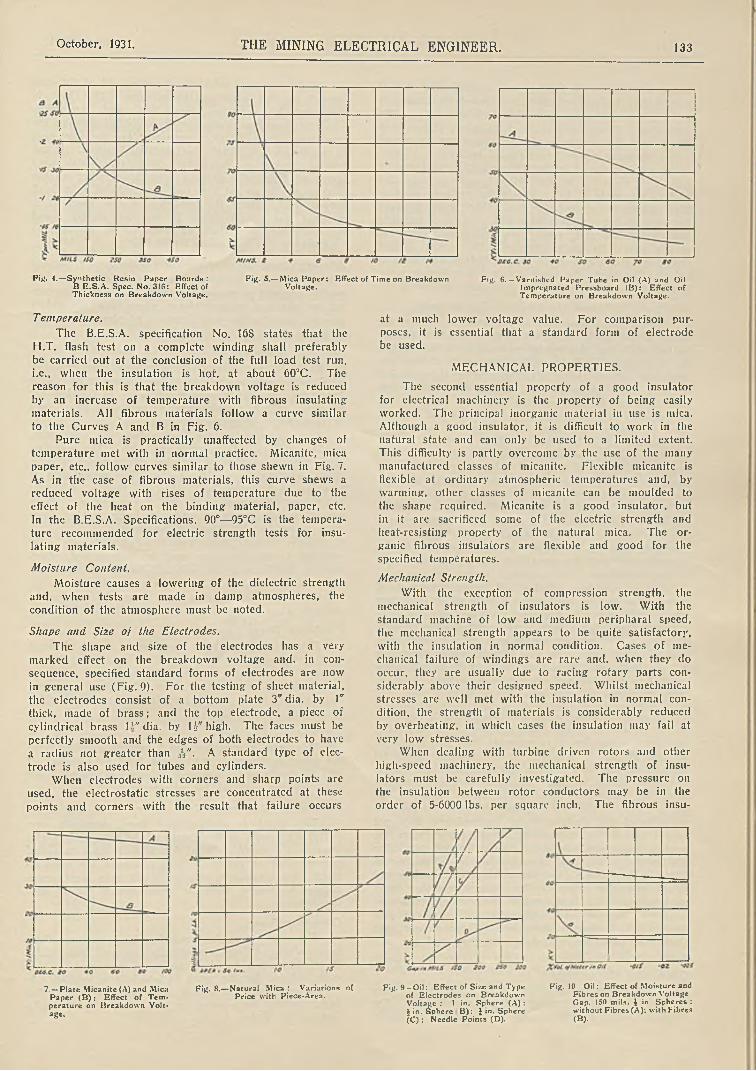
October, 1931. THE MINING ELECTRICAL ENGINEER. 133
Fig. 4.—Synthetic Resin Paper Boards : B E .S .A . Spec. No. 31(5: Effect of Thickness on Breakdown Voltage.
Fig. 5.—Mica Paper: Effect of Time on Breakdown Voltage.
Fig. 6 .—Varnished Paper Tube in Oil (A) and Oil Impregnated Pressboard (B): Effect of Temperature on Breakdown Voltage.
T emperalure.
The B.E.S.A. specification No. 168 states that the H.T. flash test on a complete winding shall preferably be carried out at the conclusion of the full load test run,i.e., when the insulation is hot, at about 60°C. The reason for this is that the breakdown voltage is reduced by an increase of temperature with fibrous insulating materials. All fibrous materials follow a curve similar to the Curves A and B in Fig. 6.
Pure mica is practically unaffected by changes of temperature met with in normal practice. Micanite, mica paper, etc.. follow curves similar to those shewn in Fig. 7. As in the case of fibrous materials, this curve shews a reduced voltage with rises of temperature due to the effect of the heat on the binding material, paper, etc. In the B.E.S.A. Specifications, 90°—95<>C is the temperature recommended for electric strength tests for insulating materials.
Moisture Content.
Moisture causes a lowering of the dielectric strength and, when tests are made in damp atmospheres, the condition of the atmosphere must be noted.
Shape and Size of the Electrodes.
The shape and size of the electrodes has a very marked effect on the breakdown voltage and, in consequence, specified standard forms of electrodes are now in general use (Fig. 9). For the testing of sheet material, the electrodes consist of a bottom plate 3" dia. by 1" thick, made of brass; and the top electrode, a piece of
cylindrical brass 1 A" dia. by l i" high. The faces must be perfectly smooth and the edges of both electrodes to have a radius not greater than A"- A standard type of electrode is also used for tubes and cylinders.
When electrodes with corners and sharp points are used, the electrostatic stresses are concentrated at these points and corners with the result that failure occurs
at a much lower voltage value. For comparison purposes, it is essential that a standard form of electrode be used.
MECHANICAL PROPERTIES.
The second essential property of a good insulator for electrical machinery is the property of being easily worked. The principal inorganic material in use is mica. Although a good insulator, it is difficult to work in the natural state and can only be used to a limited extent.
This difficulty is partly overcome by the use of the many manufactured classes of micanite. Flexible micanite is flexible at ordinary atmospheric temperatures and, by warming, other classes of micanite can be moulded to the shape required. Micanite is a good insulator, but in it are sacrificed some of the electric strength and heat-resisting property of the natural mica. The organic fibrous insulators are flexible and good for the specified temperatures.
Mechanical Strength.
With the exception of compression strength, the mechanical strength of insulators is low. With the standard machine of low and medium peripharal speed, the mechanical strength appears to be quite satisfactory, with the insulation in normal condition. Cases of mechanical failure of windings are rare and, when they do occur, they are usually due to racing rotary parts considerably above their designed speed. Whilst mechanical stresses are well met with the insulation in normal condition, the strength of materials is considerably reduced by overheating, in which cases the insulation may fail at
very low stresses.When dealing with turbine driven rotors and other
high-speed machinery, the mechanical strength of insulators must be carefully investigated. The pressure on the insulation between rotor conductors may be in the order of 5-6000 lbs. per square inch. The fibrous insu-
7. — Plate Micanite (A) and Mica Paper (B ) ; Effect of Temperature on Breakdown Voltage.
Fig. 8.— Natural Mica : Variations ofPrice with Piece-Area.
Fig. 9 - O il: Effect of Size and Type of Electrodes on Breakdown Voltage ; 1 in. Sphere (A) :£ in. Sphere B ): £ in. Sphere (C) : Needle Points (D).
Fig. 10 O il: Effect of Moisture and Fibres on Breakdown Voltage Gap. ISO mils. $ in. Spheres : without Fibres (A); with Fibres (B).
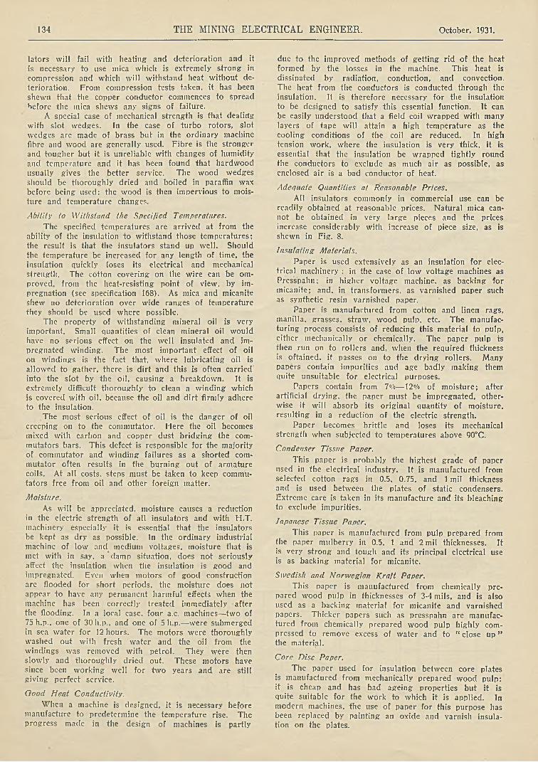
134 THE MINING ELECTRICAL ENGINEER. October, 1931.
lators will fail with heating and deterioration and itis necessary to use mica which is extremely strong- incompression and which will withstand heat without deterioration. From compression tests taken, it has been shewn that the copper conductor commences to spreadbefore the mica shews any signs of failure.
A special case of mechanical strength is that dealing with slot wedges. In the case of turbo rotors, slot wedges are made of brass but in the ordinary machine fibre and wood are generally used. Fibre is the stronger and tougher but it is unreliable with changes of humidity and temperature and it has been found that hardwood usually gives the better service. The wood wedges should be thoroughly dried and boiled in paraffin wax before being used: the wood is then impervious to moisture and temperature changes.
Ability to Withstand the Specified Temperatures.
The specified temperatures are arrived at from the ability of the insulation to withstand those temperatures: the result is that the insulators stand up well. Should the temperature be increased for any length of time, the insulation quickly loses its electrical and mechanical strength. The cotton covering on the wire can be om- proved, from the heat-resisting point of view, by impregnation (see specification 168). As mica and micanite shew no deterioration over wide ranges of temperature
they should be used where possible.The property of withstanding mineral oil is very
important. Small quantities of clean mineral oil would have no serious effect on the well insulated and impregnated winding. The most important effect of oil on windings is the fact that, where lubricating oil is allowed to gather, there is dirt and this is often carried into the slot by the oil, causing a breakdown. It is extremely difficult thoroughly to clean a winding which is covered with oil. because the oil and dirt firmly adhere to the insulation.
The most serious effect of oil is the danger of oil creeping on to the commutator. Here the oil becomes mixed with carbon and copper dust bridging the commutators bars. This defect is responsible for the majority of commutator and winding failures as a shorted commutator often results in the burning out of armature coils. At all costs, steps must be taken to keep commutators free from oil and other foreign matter.
Moisture.
As will be appreciated, moisture causes a reduction in the electric strength of all insulators and with H.T. machinery especially it is essential that the insulators be kept as dry as possible. In the ordinary industrial machine of low and medium voltages, moisture that is met with in say, a damp situation, does not seriously affect the insulation when the insulation is good and
impregnated. Even when motors of good construction are flooded for short periods, the moisture does not appear to have any permanent harmful effects when the machine has been correctly treated immediately after the flooding. In a local case, four a.c. machines—two of 75 h.p., one of 30 h.p., and one of 5 h.p.— were submerged in sea water for 12 hours. The motors were thoroughly washed out with fresh water and the oil from the windings was removed with petrol. They were then slowly and thoroughly dried out. These motors have since been working well for two years and are still giving perfect service.
Good Heat Conductivity.
When a machine is designed, it is necessary before manufacture to predetermine the temperature rise. The progress made in the design of machines is partly
due to the improved methods of getting rid of the heat formed by the losses in the machine. This heat is dissipated by radiation, conduction, and convection. The heat from the conductors is conducted through the insulation. It is therefore necessary for the insulation
to be designed to satisfy this essential function. It can be easily understood that a field coil wrapped with many layers of tape will attain a high temperature as the cooling conditions of the coil are reduced. In high tension work, where the insulation is very thick, it is essential that the insulation be wrapped tightly round the conductors to exclude as much air as possible, as enclosed air is a bad conductor of heat.
Adequate Quantities at Reasonable Prices.
All insulators commonly in commercial use can be readily obtained at reasonable prices. Natural mica cannot be obtained in very large pieces and the prices Increase considerably with increase of piece size, as is shewn in Fig. 8.
Insulating Materials.
Paper is used extensively as an insulation for electrical machinery : in the case of low voltage machines as Prcsspahn; in higher voltage machine, as backing for micanite; and, in transformers, as varnished paper such as synthetic resin varnished paper.
Paper is manufactured from cotton and linen rags, manilla, grasses, straw, wood pulp. etc. The manufacturing process consists of reducing this material to pulp, either mechanically or chemically. The paper pulp is then run on to rollers and, when the required thickness is oftained. it passes on to the drying rollers. Many papers contain impurities and age badly making them quite unsuitable for electrical purposes.
Papers contain from 7%— 12% of moisture; after artificial drying, the paper must be impregnated, otherwise it will absorb its original quantity of moisture,resulting in a reduction of the electric strength.
Paper becomes brittle and loses its mechanical strength when subjected to temperatures above 90°C.
Condenser Tissue Paper.
This paper is probably the highest grade of paper used in the electrical industry. It is manufactured fromselected cotton rags in 0.5, 0.75, and 1 mil thicknessand is used between the plates of static condensers. Extreme care is taken in its manufacture and its bleaching to exclude impurities.
Japanese Tissue Paper.
This paper is manufactured from pulp prepared from the paper mulberry in 0.5, 1 and 2 mil thicknesses. It is very strong and tough and its principal electrical use is as backing material for micanite.
Swedish and Norwegian Kraft Paper.
This paper is manufactured from chemically prepared wood pulp in thicknesses of 3-4 mils, and is also used as a backing material for micanite and varnished papers. Thicker papers such as presspahn are manufactured from chemically prepared wood pulp highly compressed to remove excess of water and to “ close u p ” the material.
Core Disc Paper.
The paper used for insulation between core plates is manufactured from mechanically prepared wood pulp: it is cheap and has bad ageing properties but it is quite suitable for the work to which it is applied. In modern machines, the use of paper for this purpose has been replaced by painting an oxide and varnish insulation on the plates.
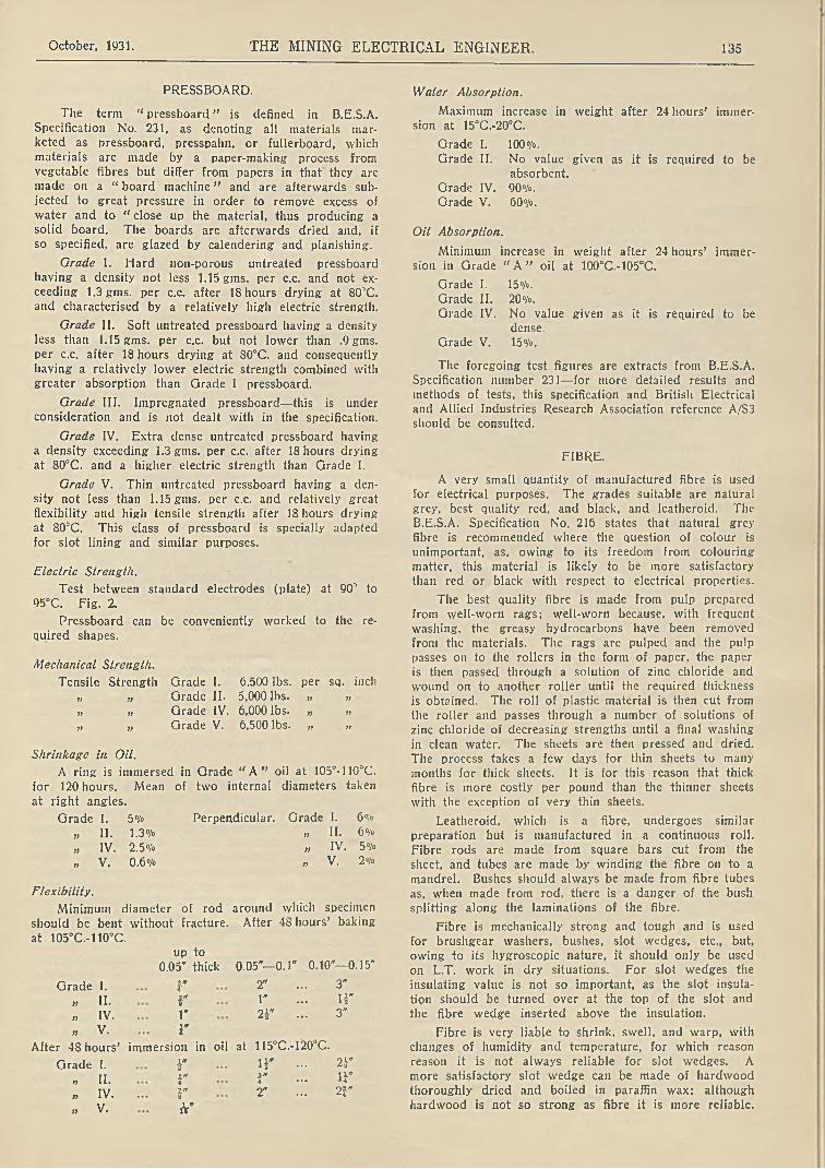
October, 1931. THE MINING ELECTRICAL ENGINEER. 135
PRESSBOARD.
The term “ pressboard” is defined in B.E.S.A. Specification No. 231, as denoting all materials marketed as pressboard, presspahn, or fullerboard, which materials are made by a paper-making process from vegetable fibres but differ from papers in that they are made on a “ board machine” and are afterwards subjected to great pressure in order to remove excess of water and to “ close up the material, thus producing a solid board. The boards are afterwards dried and, if so specified, are glazed by calendering and planishing.
Grade 1. Hard non-porous untreated pressboard having a density not less 1.15 gins, per c.c. and not exceeding 1.3 gms. per c.c. after 18 hours drying at 80’C. and characterised by a relatively high electric strength.
Grade II. Soft untreated pressboard having a density less than 1.15 gms. per c.c. but not lower than .9 gms. per c.c. after 18 hours drying at 80°C. and consequently having a relatively lower electric strength combined with
greater absorption than Grade I pressboard.
Grade III. Impregnated pressboard— this is under consideration and is not dealt with in the specification.
Grade IV. Extra dense untreated pressboard having a density exceeding 1.3 gms. per c.c. after 18 hours drying at 80°C. and a higher electric strength than Grade I.
Grade V. Thin untreated pressboard having a density not less than 1.15 gms. per c.c. and relatively great flexibility and high tensile strength after 18 hours drying at 80°C. This class of pressboard is specially adapted for slot lining and similar purposes.
Electric Strength.
Test between standard electrodes (plate) at 90’ to 95°C. Fig. 2.
Pressboard can be conveniently worked to the re
quired shapes.
Mechanical Strength.
Tensile Strength Grade I. 6,500 lbs. per sq. inch „ „ Grade II. 5,000 lbs. „ »„ „ Grade IV. 6,000 lbs. „ „„ „ Grade V. 6,500 lbs. „ „
Shrinkage in Oil.
A ring is immersed in Grade “ A ” oil at 105°-110°C. for 120 hours. Mean of two internal diameters taken
at right angles.
Grade I. 5°/o Perpendicular. Grade I. 6°/o
„ II. 1.3°/o „ II. 6«/»„ IV. 2.5 o/o „ IV. 5°/o
„ V. 0.6°/o „ V. 2°/o
Flexibility.
Minimum diameter of rod around which specimen
should be bent without fracture. After 48 hours’ baking
at 105°C.-110°C,up to
0.05" thick 0.05"— 0.1' 0.10"—0.15*
Grade 1. 3.»4 2" ... 3"
„ 11. r 1" ... H"
„ IV. 1* 2Y ... 3"
„ V. r
After 48 hours’ immersion in oil at 115°C.-120°C.
Grade I. ¥ i r ... 2 i"
„ II. r r ... i f
„ IV. i*8 2" ... 2J-"
„ V. h"
Water Absorption.
Maximum increase in weight after 24 hours’ immersion at 15°C.-20°C.
Grade I. 100°/o.
Grade II. No value given as it is required to beabsorbent.
Grade IV. 90°/o.Grade V. 60°/o.
Oil Absorption.
Minimum increase in weight after 24 hours’ immersion in Grade “ A ” oil at 100°C.-105°C.
Grade I. 15°/o.Grade II. 20°/o.Grade IV. No value given as it is required to be
dense.Grade V. 15°/o.
The foregoing test figures are extracts from B.E.S.A. Specification number 231—for more detailed results and methods of tests, this specification and British Electrical and Allied Industries Research Association reference A/S3 should be consulted.
FIBRE.
A very small quantity of manufactured fibre is used for electrical purposes. The grades suitable are natural grey, best quality red, and black, and leatheroid. The B.E.S.A. Specification No. 216 states that natural grey fibre is recommended where the question of colour is unimportant, as, owing to its freedom from colouring matter, this material is likely to be more satisfactory than red or black with respect to electrical properties.
The best quality fibre is made from pulp prepared from well-worn rags; well-worn because, with frequent washing, the greasy hydrocarbons have been removed from the materials. The rags are pulped and the pulp passes on to the rollers in the form of paper, the paper is then passed through a solution of zinc chloride and wound on to another roller until the required thickness is obtained. The roll of plastic material is then cut from the roller and passes through a number of solutions of zinc chloride of decreasing strengths until a final washing in clean water. The sheets are then pressed and dried. The process takes a few days for thin sheets to many months for thick sheets. It is for this reason that thick fibre is more costly per pound than the thinner sheets with the exception of very thin sheets.
Leatheroid, which is a fibre, undergoes similar preparation but is manufactured in a continuous roll. Fibre rods are made from square bars cut from the sheet, and tubes arc made by winding the fibre on to a mandrel. Bushes should always be made from fibre tubes as, when made from rod, there is a danger of the bush splitting along the laminations of the fibre.
Fibre is mechanically strong and tough and is used for brushgear washers, bushes, slot wedges, etc., but, owing to its hygroscopic nature, it should only be used on L.T. work in dry situations. For slot wedges the insulating value is not so important, as the slot insulation should be turned over at the top of the slot and the fibre wedge inserted above the insulation.
Fibre is very liable to shrink, swell, and warp, with changes of humidity and temperature, for which reason reason it is not always reliable for slot wedges. A more satisfactory slot wedge can be made of hardwood thoroughly dried and boiled in paraffin wax: although hardwood is not so strong as fibre it is more reliable.

136 THE MINING ELECTRICAL ENGINEER. October, 1931.
Lealheroid.
This material is largely used on L.T. and medium tension machines, it is tough and resists abrasions and thus it is very suitable for placing between a micanite trough and the sides of the core slots as protection for the micanite, as well as between the micanite and the
coil.
Vulcanised Fibre.
Tests to be carried out are given in B.E.S.A. Specification No. 216. Extracts from the tests are as follows:
Freedom from Conducting Particles.
Samples are passed between a metal plate and rollers, an alternating voltage of 50 volts per mil of thickness is applied. The samples shall not shew an average of more than two punctures per square yard. Three samples, each sample not less than one square yard, shall be tested and the mean number of punctures shall be taken. This test applies to samples up to thick.
T ensile Strength not less than (taken from curve) :
Thick With the grain Against the grain1 »
32 11,000 lbs. per sq . inch 6,000 lbs. per sq. inch
fa" 13,000 )> if 8,000 )) jf
r 13,000 n i) S,000 v „
r 12,000 )) 7,000 ))1»a 10,800 » >7 6,000 yy j)
r 9,600 }) if 5,000 )> „
Shearing Strength, minimum value
Up to and including i" 14,000 lbs. per sq. inch
r „ r 12 ooo „r „ ¥' 9,000 „
Both ways of grain.
Electric Strength.
Up to and including -fa" 200 volts per mil.
fa" to i* 6,250 „ „
Note 1.— It is not considered necessary to give values over i* thick.
Note 2.— When employed in dry situations, fibre shall not be subjected to a permanent working electric stress greater than 20 volts per mil. In damp situations, vulcanised fibre shall not be regarded as a satisfactory electrical insulating material.
Shrinkage in Air.
Samples 4" square are taken and conditioned in a controlled atmosphere of 75% humidity and temperature 15‘C.-25°C. Samples are then dried for 48 hours at a temperature of 105°C.-110°C.
Dimensions shall be taken from a number of places and the mean values used for calculating the percentage shrinkage. Shrinkage shall not exceed :
With Against Size the grain the grain Thickness
Up to and including fa” 1% 2% 5%
fa" to i" .8°/» 1.5°/o 5°A>
Shrinkage in Oil.
Test rings, 4" diameter inside, 6" diameter outside, shall be conditioned in a controlled atmosphere of 75°/° humidity and 15°C.-25CC. temperature for not less than IS hours. The rings shall be placed in transformer oil for 120 hours at 105°C.-110°C. A number of dimensions
shall be taken and the mean used for calculating the % shrinkage. Shrinkage shall not exceed :
With Against Size the grain the grain Thickness
Up to and including fa" 2.5% 2.5°/o 4%fa" to i" 2% 2°/o 4%
Water Absorption.
The samples are conditioned by drying and afterwards placed in a controlled atmosphere of 75% humidity; then immersed in water for 24 hours.
Up to and including fa” 55% by weight (max.)
fa" „ V 25%V „ i" 15%r » v 15%h* » 1" 15% „
Flexibility.
Samples are conditioned by drying for 18-24 hours
at a temperature of 75°C.-80°C. and allowed to cool in a temperature of 15°C.-25°C. The baking consists of 48 hours at a temperature of 105°C.-110°C. and allowed to cool to 20°C. (plus or minus 5°C.) in a controlled atmosphere of 75% humidity.
The samples are bent round a mandrel through ISO1' and must shew no signs of cracking, splitting, or chipping.
Size Before Baking After BakingUp to and including fa" fa" rod of mandrel §"
to fa” r » 1"fa" to r r „ ¿ if
Slot Wedge Test.
Samples are made 4" long and fa" and £" thick with rounded sides and placed in a jig similar to a core slot. A compression test is then applied to force the fibre from the slot.
Wedge fa” thick ... 3,000 lbs. (min.) per inch of lengthWedge thick ... 5,000 „ „ „
The above summary gives a concise statement of the more important tests which are made. Details of the apparatus used in the testing, and the methods of test will be obtained by reference to the complete specification.
COTTON AND FABRICS.
Cotton occupies an important place in electrical machinery. Coils are usually wound with cotton covered wire, afterwards impregnated, and frequently with no other insulation between turns. A failure of the cotton covering often results in the coil burning out. The cotton is spun into threads and wound on to the conductor in the form of a number of threads in parallel. Single cotton covering consists of one layer of cotton. Double cotton, two layers, the second layer is wound in a direction opposite to the first. Triple covering, the centre covering is wound opposite to the inner and outer layers. Cotton covering is divided into two main classes, one termed ordinary and the other specially fine which occupies less space than the ordinary covering. Single cotton covered wire should only be used on d.c. field coils, shunt brake coils, etc., where the voltage between turns is low and where a short between turns is not likely to be of serious importance. But in all these coils D.C.C. specially fine can be used and will occupy about the same space making a better coil but more costly. Double cotton covered wire, either ordinary covering (or, where space is limited, specially fine covering) are always used on small wires for armatures, stators, rotors, and all other a.c. coils.

October, 1931. THE MINING ELECTRICAL ENGINEER. 137
Increased. Diameter in Inches due to Coverings for Wires (Cotton and Silk).
S.C.C. D.C.C. D.C.C.S.W.G. (ord.) (s./.) (ord.) SSC. DSC. Enamel
16s. 0.007 0.009 0.012 0.003 0.0045 0.003522s. 0.006 0.006 0.010 0.002 0.0035 0.00230s. 0.006 0.006 0.010 0.0015 0.0025 0.001510s. 0.004 0.005 0.008 0.0015 0.00225 0.0007
In heavy section coils of either round or rectangular section, braiding is used. The braiding is formed by interlacing the threads on the conductor. Braiding is thicker than double cotton covering but usually more space is provided for the covering on larger conductors. For extremely heavy section conductors for large series colls and interpole coils, the coils are formed with bare copper and afterwards taped, or insulation inserted between turns. In H.T. work where the voltage between conductors is above 25 volts, triple cotton covering or single covering with braiding is employed.
Tapes.
Cotton is also used as tapes. Three types of tape are usually employed: American cotton tape for small field coils, etc.; Egyptian tape, finer and thinner than American, is used on armature, stator, rotor coils, etc.; webbing tape, an exceptionally strong cross woven tape used on large field coils etc. where strength is required. This last is, incidentally, also useful in the ambulance box for strong bandages.
Cotton is a hygroscopic substance, the moisture content being 70/o-S0,'o. If left in the atmosphere afterdrying, it will readily absorb its initial quantity of moisture. For satisfactory insulation between turns it is essential that the cotton be thoroughly dried, preferably under vacuum, and then impregnated with suitable varnish before the cotton is again exposed to the atmosphere. Cotton deteriorates rapidly at temperatures above 90°C.
Fabrics.
Cotton cloths are used (Jxtensively as insulatingmaterials. Varnished cloth or empire cloth is a cotton fabric treated with a linseed oil base varnish. The process of making varnished cloth consists of filling the pores of the cloth and making the surface free from nap and loose fibres as these would puncture the varnish film and reduce the electric strength. After thorough drying, the cloth is passed through the varnish andslowly through drying ovens. The varnished cloth is sold 36" wide of varying thicknesses from 0.005" to0.015", yellow or black; and as tape of varying widths. In order to make the tape stronger, the tape is cut from across the cloth at 45°, the ends of the short lengths of tape are then sewn together. Tills is termed “ bias cut ” tape. Bias cut tape can also be obtainedwithout joints: the cloth from which this tape is cut si woven tubular and the tape cut from around the circumference of the tubular cloth. Tape without joints is more costly but there is no waste and neater taping
can be done.
Varnished cloth and tapes are used extensively on
transformer, and for the projecting parts of generator and motor coils. The tape can be readily wrappedaround the coil neatly: care should be taken that the tape is not overstretched as there is a danger of the varnish film being broken rendering the tape no better
than ordinary cotton tape.
Varnished cloth rapidly deteriorates at temperatures
over lOOdeg. C.; it absorbs a small amount of moisture but it is not affected by hot mineral oils. It will not withstand abrasion owing to possible damage to the
varnish film and it is weak in compression compared with mica and presspahn.
Cotton cloth is also used as a supporting medium for synthetic resin varnish and pressed together in the form of cylinders and boards. It is also used as a backing for micanitc and as canvas for the protection of motor end-windings for working in dirty situations.
MICA AND MICANITE.
As an insulation, mica is used more extensively than any other one material: several of the other insulators though good, are in many cases used as a supporting or protecting material for the mica. It has exceptionally strong qualifications for premier place amongst insulators for clectrical machinery—-it has a high electric strength, absorbs very little moisture, withstands very high temperatures without deterioration; is unaffected by age, strong in compression, does not shrink and is unaffected by oil, alkalies and acids. The disadvantages of mica arc, that it cannot always be worked to the required shapes and it is only obtainable in comparatively small pieces. These two disadvantages are overcome by the manufactured product of mica called micanitc, but the use of micanite sacrifices some of the properties of natural mica.
Mica is a mineral consisting of silicates of aluminium, potassium, and magnesium and, for clectrical purposes, obtained from India and Canada. It is usually graded by its content inclusions. These inclusions often consists of iron and other Impurities which affect the electric strength. These impurities run in parallel films between the laminations and, as the voltage stress is usually at right angles to the laminations, the inclusions do not seriously affect the electric strength. The breakdown voltage of stained or spotted mica is not usually less than 75°/« that of clear mica. There are many grades of mica obtainable but those commonly used as insulators are as follows:—
Clear Ruby Mica. This is obtained from India, has a very high electric strength (1600 volts per mil) and is free from inclusions. It is used in the manufacture of micanite for H.T. and E.H.T. work.
Stained Ruby Mica. Similar to Ruby but. owing to impurities, it has a lower electric strength (1200 volts per mil). This is cheaper than clear ruby but quite good for medium and H.T. work.
Hard Spotted Mica. A good insulator for medium pressure work, at a low price. It is very useful for insulating binding bands from the core and windings (where mica should always be used as there is nopossibility of the mica shrinking and causing a loose band).
Amber and Silver Amber Mica. These micas are obtained from Canada and are soft and should be used for commutator segment micas where the micas are left flush with the bars.
Owing to the difficulty in working natural mica, micanite is used in large quantities. Micanite has alower electric strength than natural mica and its heat- resisting properties are not so good, but it shews no deterioration with normal temperatures. Micanite is also affected by oil causing the sheet to split up into flakes if these are not held securely together.
There are three main classes of micanite:—
(1) Flexible Micanite.
(2) Moulding Micanite.
(3) Commutator Micanite.

138 THE MINING ELECTRICAL ENGINEER. October, 1931.
Flexible Micanite. This is built up of mica flakes, the best quality from clear ruby mica. These flakes are held together by a flexible varnish. It can be obtained without a backing material but is also supplied with a paper, cotton, or silk backing. It can be formed into shape whilst cold, e.g., a slot lining trough.
Moulding Mica Plate. The best qualities of this are made from clear ruby flakes. The flakes are cemented together with a varnish which softens at 250 deg. F. The plates are carefully built up and pressed with hydraulic pressure and afterwards milled to the required uniform thickness. The plates are made from 0.01 in. thick, sold by the pound, and the price is slightly less as the thickness increases. It is used as an insulator for windingsupport rings, slot troughs, commutator cone rings, etc. It contains 10% of binding material. It can be formed to the required shapes by warming, and retains the shape when cold.
Hard Micanite Plate. This is somewhat similar to moulding micanite but it will not mould. It is useful for flat washers, etc.
Clear Indian Commutator Micanite. This is manufactured from flakes, similar to moulding micanite with the important exception that the binding material must be reduced to a minimum—not more than l°/o. This is necessary in order to prevent looseness of the commutator bars with changes of temperature. It is madein sheet three feet square, 0.01 in. to 0.04 in. thick. Thesheets are milled to give uniform thickness.
Amber Commutator Micanite. This is manufactured from amber mica flakes, it is soft and will wear down evenly with the copper bars. It is 50°/o dearer than Indian commutator micanite. Commutator micanite is not flexible, the flakes will separate if the micanite is bent.
Micafolium. This is a moulding micanite with a paper backing, it will bend when warm and retain its shape when cold, used extensively for micanite tubes and cylinders.
INSULATING OILS.
Insulating oil as used in transformers and switch- gear is a mineral oil, refined from crude petroleum. The oil, when new, is colourless or a pale yellow. When in use and heated in the presence of oxygen the colour changes to yellow, orange, red, and dark red.
The B.E.S.A. Specification number 148— 1927, dealswith the procedure for the testing of oils. This specification specifies two grades of oil, according to the tendency to form sludge. Sludge is an asphalt compound rich in oxygen (deposited in the oil by heating the oil in the presence of oxygen) and a catalytic agent such as copper. The main duty of transformer oil is cooling: when sludge is formed, it sticks to the windings and in the oil ducts and, as it is a bad conductor of heat the windings become overheated with more and more sludge formation until a breakdown occurs. It is therefore important that insulating oils be specifiedin terms of tendency to sludge.
Class “ A ” Oils. Sometimes referred to as nonsludging oils, the Class A are suitable for transformers in which the working temperatures of the oil measured by thermometer exceed 80 deg. C. These oils are also suitable for switches in which the working temperature exceeds 70 deg. C. They may also be used to advantage in all oil switches above 500 ampere capacity hav- nig their main contacts under oil and operated for long periods near their rated current, or in hot situations.
Class “ B ” Oils. These are suitable for transformers in which the working temperature of the oil does not usually exceed 75 deg. C. They are also suitable for general use in oil switches not subejcted to conditions requiring the use of class “ A ” oils. By the use of expansion tanks where the access of oxygen may be effectively prevented, thereby reducing the tendency to sludge, class “ B ” oils may be used where class “ A ” would otherwise be required. Many tests are carried out on transformer oils but the more important are:—
(1) Sludge Test.(2) Viscosity.(3) Electric Strength.
Sludge Test. A sample of oil is heated to 150 deg. C. and the temperature kept constant for 45 hours. A piece of highly polished copper is placed in the oil for the test. Air at the rate of 0.07 cubic feet per hour
through the oil. The air is first dried and cleaned by passing through wash bottles of sodium hydrate solution, silver nitrate solution, and concentrated sulphuric acid respectively. At the conclusion of the test, the sludge is filtered out, dried, and weighed. The amount of sludge for class “ A ” oils should not exceed 0.1°/» and for class “ B ” 0.8%.
Viscosity. To operate satisfactorily as a cooling medium, the viscosity should not exceed that specified at low temperatures. For the test, a Redwood No. 1 Viscometer is used, the oil passing through the jet. The viscosity of classes “ A ” and “ B ” oil shall not exceed 200 seconds at 15.5 deg. C.
Electric Strength. It is essential that the oil should have a high electric strength value. The test is carried out by placing a sample of the oil in a standard test cup. The sample not less than 300 c.c. The electrodcs are 13 mm., a little over ^ in., diameter spheres. The gap between the spheres 4min., nearly 0.16 in. The spheres are arranged horizontally. The temperature of the sample shall be between 15.5 deg. C. and 20 deg. C. Minute quantities of moisture, especially with fibres float
ing about, seriously affect the electric strength (Figs. 9 and 10).
Special care must by taken when obtaining the sample to ensure that the sample is a fair representation of the whole. Special sample bottles are provided: it is useless to use an ordinary bottle. The sample is usually taken from the bottom of the tank and a small quantity of oil should be allowed to pass from the drain before the sample is taken to enable the drain to be washed with oil. In some of the older transformers drains are not fitted and a sampling tube has to be used. The tube must be thoroughly clean and dry—the tube is placed in the oil. The thumb is then placed over the tube at the top end and a sample of oil withdrawn. When the sample is obtained, it is placed in the test cup after being well shaken. Air bubbles should be allowed to disperse before taking the test. The a.c. voltage is gradually increased to 30k.v. which the sample shall stand for one minute. The oil shall pass if two samples out of three are satisfactory. The applied voltage shall be of sinusoidal wave form and of any frequency between 25 and 100 periods per second.
Whilst undergoing test, sparking sometimes occurs across the gap, this may be ignored, the complete breakdown is indicated by the formation of an arc and the tripping of the circuit breaker usually placed in the transformer L.T. circuit. Other tests are taken, such as test for acid, flash-point, evaporation and cold test.
From a maintenance point of view, the transformer oil should occasionally be examined and tested. A visual examination will reveal sludging of the oil. The sludge

October, 1931. THE MINING ELECTRICAL ENGINEER. 139
is a dark slimy substance which floats in the oil. Where sludge is formed in considerable quantities, the oil should be filtered by means of a filter press or centrifugal separator and the winding and core thoroughly cleaned. An electric strength test can also be taken and, if (here be water present, this can also be removed by filter press or separator. In bad cases of sludging it is advisable to discard it and recharge with new oil.
SYNTHETIC RESIN PRODUCTS.
This insulation of recent development now holds a most important position. Synthetic resin is a product of the condensation of phenol (carbolic acid) with formaldehyde (a gas obtained by the partial oxidation ol methyl alcohol). Formaldehyde is largely used as a disinfectant and antiseptic, the antiseptic smell can be readily noticed when cutting synthetic resin products.
The commercial development is largely due to Dr. Baekeland and is known by various trade names as Bakelite,
Micarta, Miocarta, etc.
The initial product is a liquid, used as a varnish for impregnating paper from which insulating boards and cylinders arc made and cloth also made into boards and cylinders and, owing to its mechanical strength, small gear wheels are made from the impregnated cloth. The liquid is heated to form a soft plastic substance for moulding purposes which hardens when cold and, with heating and pressure, the hard solid material is obtained.
Synthetic resin varnish boards are dealt with in
B.E.S.A. Specification No. 316— 1929, two grades are
specified :Grade 1. Boards. These have low water absorp
tion, high resistivity, low dielectric loss at radio frequencies and good machining properties. This grade is generally employed on apparatus where it is important that high insulation resistance shall be maintained under all conditions of humidity and for use at radio
frequencies.Grade 2. Boards. These are of high electric strength
at high temperatures; this grade is generally applied on oil-immersed apparatus and low voltage apparatus in air. The B.E.S.A. specification deals with the tests to which this material is subjected: Grade 2 tests only are given: tests for Grade 1 material are at present
being considered.
Electric Strength.
This test is taken between two standard electrodes in Grade “ A ” transformer oil at 90 deg. C. The test
for tubes is made by inserting a cylindrical electrode in the tube and a metal band on the outside. (Sec Fig. 4) Minimum volts per mil: 250, up to |in. thickness of wall. Minimum volts per mil: 200 above I in- up to and
including Jin.This insulator can be conveniently worked and
moulded to the required shapes.
Mechanical Strength.
Tensile strength: 10,000lbs. per square inch. Compression: 3°/o when subjected to a load of 10,000 lbs. per square inch, will withstand high temperatures with
out deterioration.
Water Absorption.
After 24 hours’ immersion, the water absorption shall
not exceed :
h" thick ... 4°/o
r V ... 2°/o
i ' f f ... 1.7»/«
r n ... l°/0
Effect of Hot Mineral Oil.
A piece 3" square shall be immersed in hot Class “ A ” transformer oil for 24hours at 110°C. to 115°C. and shall shew no signs of warping, splitting, blistering, or other deterioration.
For a . complete guide as to the methods of tests adopted, Specification number 316 should be consulted.
Synthetic resin products are used extensively for transformer and switchgear insulation and, with asbestos, for the insulation of turbine driven alternator rotors and windings.
ASBESTOS.
This is used to a limited extent as covering for small wires in place of cotton, for insulating some types of field coils, lifting magnet coil insulation and, in conjunction with synthetic resin, as a solid insulator.
Asbestos is very hygroscopic and mechanically weak —whenever it is used, it should be thoroughly dried —and impregnated to make it non-hygroscopic. In the case of wire covering, the asbestos is placed on the wire in the form of a pulp and treated with varnish.
The important feature with asbestos is that it will stand very high temperatures without deterioration.
Asbestos is also obtainable as tape from 5 mil. thickness and there are many asbestos compound boards obtainable—one we have found very suitable for the insulation of sliprings.
SILK.
Silk is used for the covering of very fine copper wires because it is much finer and takes up less space than cotton. It is hygroscopic and should be varnished but the varnish used should be dried very quickly as there is a danger of minute quantities of acid being present which would cause corrosion of very fine copper wires. Silk is also used as sheet insulation in the form of oiled silk for insulating between layers on small work and for potential instrument transformers on theH.T. side. It is also supplied as tape and as a backing for mica tape.
OXIDE.
In a few cases, the oxide of metals is used as an insulation. The most common is the oxide of iron for insulating core plates. The formation of oxide is assisted by treating the plates. It is also used for the insulation between turns on aluminium wire for traction field coils and for aluminium wire lifting magnets. This is quite good, as the ageing properties are good, also the electric strength is good as the voltage between adjacent turns is exceedingly small.
VARNISH.
Many insulating materials depend ultimately for their electric strength upon the varnish with which they are impregnated or covered. Cotton, paper, asbestos, etc., are hygroscopic and, without varnish, would absorb moisture from the atmosphere and would soon fail as insulators. It is the varnish film on empire cloth which gives it a high electric strength: damage to this film renders the cloth no better than ordinary cotton cloth. It is therefore most important that special attention be given to the application of varnish to the insulation.
Varnishes consist of gums, asphaltum, rubber, waxes, oils, driers, and solvent. The principal gums used are copals, succin, gum dammer, sanderac gum, gum mastic, turpentine, and gum lac (shellac). These gums are obtained from trees, fossil, and, in the case of shellac, from the lac insect which sucks the secretions from the trees. The oils used are obtained from vegetation.

140 THE MINING ELECTRICAL ENGINEER. October, 1931.
such as linseed oil, cotton-seed oil, castor oil, poppyseed oil, resin oil, and wood oil. The drying of varnish consists of the oxidation of the oils, to accelerate this oxidation, compounds of lead, manganese and cobalt are added which, on heating, give up oxygen to the oils to assist oxidation. The selection of suitable driers is carefully considered by the manufacturers, as unsuitable driers may result in the formation of acids or metallic salts which may cause trouble. The solvents in general use consist of methylated spirits, benzine, carbon bisulphide and spirits of turpentine.
Varnishes may be divided into three main classes :1. Bonding varnish.2. Impregnating varnish.3. Finishing varnish.
Bonding Varnish. This varnish is extensively used for the building of micanite, micafolium, iiexible mica- nite, mica cloth, varnished paper, etc. It may be divided into two classes— (a) flexible at ordinary temperatures,(b) flexible when warm. Copal varnish is generally used where flexibility at ordinary temperatures is required such as for flexible micanite, mica paper, varnished paper, etc. : the copal gums are dissolved in a solvent and a small amount of castor or similar oil for flexibility. Shellac varnish is used where material is made flexible by warming such as moulding micanite, micafolium, etc. Synthetic resin varnish is also used as a bonding varnish for paper, cloth, and asbestos.
Impregnating Varnishes.
These are the varnishes used for the impregnating of windings and coils. The varnish is usually a linseea oil base with driers and a suitable solvent. This varnish is made for drying in air from 30 to 60 minutes whichis particularly suitable for quick repairs carried outon site and, as is more generally used, a baking varnish which is dried in an oven at 1S0°F. from 2 hours for small work, to 6 hours for large parts. The varnishes are plastic, withstand high temperatures, vibration, and can also be obtained as alkali and acid resisting.
The manufacturers particularly stress the importance of having the insulation bone-dry before applying thevarnish. This can best be obtained in a suitable vacuum impregnating plant. The parts to be impregnated are placed in a heated chamber and the air withdrawn from the chamber ; 29" of vacuum can be obtained in thechamber and, with this degree of vacuum, water boils at about 80°F. with the result that the insulation can be thoroughly dried at a very low temperature without damage from overheating. The vacuum is broken by allowing the varnish to flow into the chamber and cover the w. ndings, coils, etc., and then compressed to force the varnish into the insulation. The whole process is completed before the insulation is exposed to the atmosphere.
It is sometimes noticed that the insulation has become a greenish colour after a machine has been in commission some time : this greening is apparently due to some corrosive agent in the cotton or varnish. There is no doubt that this greening is accelerated by moisture and all steps must be taken to remove thoroughly the moisture before applying the varnish. Some engineers consider that the linseed oil is the cause of the greening ; an impregnating varnish can now be obtained free from linseed oil, this varnish is also oil-resisting but it takes rather longer to dry, 3-10 hours at 212°F.
Varnishes are also made hot oil proof and are particularly suitable for oil-immersed transformers.
finishing Varnishes.
A finishing varnish is used by brushing or spraying on to a completed winding. These varnishes are tough.
flexible and glossy ; they resist damp, acid, and oil, and should be applied when the windings are dry and warm. They are copal and dyed shellacs and dry in a few hours at ordinary atmospheric temperatures.
LOW AND MEDIUM VOLTAGE MACHINES.
This class comprises the majority of d.c. armatures and field coils, and a.c. stators and rotors.
D.C. Armatures.
The insulation may be divided into four sections, viz.:—
Insulation between turns.
Slot insulation between windings and core, and between coils in the slot.
End winding insulation between coils and coil support rings, and insulation between coils.
Commutator Insulation.
The insulation between turns usually consists of the covering of the wire (double cotton), in heavy section strip coils there is, at times, room for a thin strip of Leatheroid or Presspahn between bars in the slot.
The slot insulation, as a minimum, consists of a micanite trough, and leatheroid for the protection of
the mica. The insulation between coils in the slot is important as full line voltage exists at this point (Fig. 11).
A micanite strip can be inserted and a hardwood wedge placed on top. Frequently, coils are very tight in the slot with a minimum of room for insulation, in these cases more room can be provided by using specially fine cotton covered wire. Wherever possible, wood wedges should be placed on the top of the coils as a protection for the coil against dirt and oil and mechanical protection in the case of worn bearings when the armature rubs on the pole faces (Fig. 12).
Coil support rings are insulated with micanite and micanite placed between the coils. Full line voltage exists between coils on the end-windings. The connections to the commutator are reinforced with cotton sleeves and these connections are insulated from the coils by strips of empire cloth between the bottom connections and the coils, and flexible micanite between the top connections and the coils. The band insulation consists of hard mica and there is no danger of the mica shrinking to cause a loose band.
The end ring and bush insulations of the commutator consists of moulding micanite with amber mica or amber
commutator micanite between the bars (Fig. 12).
Field Coils.
Shunt field coils are wound with either single cotton covered wire, double specially fine, double cotton ordinary, or enamelled wire. Double cotton specially fine can be used where single covering is used and occupies about the same space. Shunt coils should be
Fig. 11.—Armature Coils shewing Full Line Voltage between End Windings.

October, 1931. THE MINING ELECTRICAL ENGINEER. 141
A — >38 Co*oucroAS, '08" DI a.: CorfitAflrtcA '/6a ": Sa*c£/acto*$2% B — ” " , ’0i*'08 : - * '¿I0".' * » 40\TC - 8 * 0 7 - - ‘2Z°: • - 46Z
— YJOOD WCOGC
-SLOT L IN IN G 'O f f LEA THCROtO ‘00r MtCAMTC • OC/ L CA THCROIO
•o i s m i c a n i t c
? z zm
Fie. 12.—Details of D.C. Armature Insulation.
wound as near as possible in layers 011 a field coil winding machine—with this method, more turns can be got on to the coil in the same space than when the coil is wound with a large number of crosses between turns.
Series and Interpole Coils.
In the small sizes, these are wound with cotton covered wire either round or rectangular section. In the larger sizes, braided covered wire is used and, in the still larger sizes, bare copper strip is used and taped with cotton tape after winding, or with thin presspahn between turns and the edges of the copper left bare. Field coil insulation from the frame consists of a moulded micanite sleeve on the pole and hard micanite washers on the ends of the coils. The coils are then taped with a suitable cotton tape, dried under vacuum, and impregnated.
A.C. STATORS AND ROTORS.
A.C. stators, low and medium voltages, are wound with double cotton covered wire for the smaller sizes and rectangular strip conductors for the larger ones. In the case of the wire wound, we have four types of winding, as follows:—
Pull through type, where the wire is pulled through the slot turn for turn. In this case a trough is made of micanite and leatheroid and the end windings taped with one layer of empire cloth tape A lap, and one layer of cotton tape J lap. This type of winding is dying out owing to the cost of the winding.
Basket or mesh type : the coils are former wound completely filling two slots, the coils are threaded through the partially opened slots, a wire at a time; the slot insulation consists of micanite and leatheroidwith a wood wedge at the top, and the end windings are taped with one layer of empire cloth and onelayer of cotton tape. Round wire is always used for this type of winding as difficulty is experienced in preventing crosses on the end windings which would cause trouble with rectangular section wire.
Diamond shaped coil winding. This winding issimilar to ordinary d.c. armature winding where the coil occupies 2J slots. The coils are threaded through
the partially opened slot at the top, a wire at a time.The slot insulation consists of micanite and leatheroidand, in addition, insulation has to be placed betweenthe coils in the slot. In some makes of motors, the
two half coils in the same slot are in different phases in which case, the insulation between coils has to be good, usually 25 mil. micanite strip is placed at this point. The end windings are taped with empire tape 5 lap and cotton tape J lap, one layer each.
Chain winding is composed of former wound coils, but arranged in two or three tiers. The wires are threaded through the top of the slots as previously and the end windings taped with empire and cotton tape. This type of winding is rather more expensive than the mesh or basket type, as additional formers are required and extra time is spent in winding the coils. (Fig. 13.)
Rotor windings are similar to stator windings in type and the insulations from the core and winding supports are similar to armature windings. Large a.c. low and medium voltage, stators and rotors are usually bar wound with rectangular conductors. The insulation is usually formed on the bars before placing the bars in the slot, the insulation consisting of micanite and leatheroid. The bars are usually pushed through the slots from one end: the top layer of bars is then connected to the corresponding bottom bars by solderedclips. The insulation on the end winding consists of empire and cotton tape with micanite between the top and bottom layers.
The insulation of the end windings of all a.c. stators and rotors is important as there is full line voltagebetween adjacent coils at the terminal ends: the voltage is less as the windings approach the star point connections but it is usual to insulate all the coil end windings the same with empire and cotton tape, or “ emlin ” tape which is a combination of empire tapebacked with linen tape (Fig. 14).
The foregoing types are specified by B.E.S.A. specification 1GS-
Temperature Rise.
Temperature Rise for Class “ A ” Insulation:Continuous Rating.
Windings ...........................................................40° C.Commutator ...........................................................45° C.Sliprings ........................................................... 45° C.Enclosed Sliprings ...................................................55° C.
The final temperatures for all classes shall not exceed 90° C. as specified by the International Electrotechnical Commission.
CONOUCTOK
A-'i&tr C- -/SS D it.
com*AfCA JJ o' ■S04a‘ H 4-o-
Fig. 13.—Details of A.C. Motor Stator Insulation.

142 THE MINING ELECTRICAL ENGINEER. October, 1931.
Temperature Rise: Short Rating and Totally Enclosed.Windings ............................................................50° C.Commutators ............................................................ 55° C.S lip rings ....................................................................... 55° C.
Insulation Flash Test.
Machines; 1 h.p. or k.w. to below 3 h.p. or k.w. : 1000 plus twice the working voltage.
Machines; 3 h.p. or k.w. and above: 1000 plus twice the working voltage with a minimum of 2000 volts.
Rotors; Non-reversing: 1000 plus twice the open
circuit volts.
Rotors; reversing: 1000 plus four times the open circuit volts.
Although not specified, the above tests should also be applied between phases and between shunt and compound coils.
Rated Volts.Insulation Resistance-----------------------------
1000 plus Output in h.p. or k.w. tested with 500 volts testing set.
For small 500 volt machines this would be approximately 0.5 megohm.
HIGH TENSION INDUCTION MOTORS.
The rotors of these motors are usually of low voltage and the insulation consists of mica paper wrapped round the bars and the bars pushed through the slots and bent to form either a lap or a wave winding: the wave winding is the more common as fewer end connections are required. The adjacent bars of two different phases are insulated with empire tape and moulding micanite between top and bottom bars at the end
windings.
The stators of these motors are wound according to the type of slot, partially open and full open. With the partially open slot, two types of winding are in use. The pull through winding, in which the conductor is pulled through the slots, using a long length of conductor. When the number of turns per slot is large, the conductors are arranged in either two or three rows, with insulation between rows. This can be arranged in two ways, firstly by starting at the bottom of the slot and winding to the top in one row, crossing over, and starting at the bottom of the second row. With this method, the voltage between adjacent conductors is the voltage per turn multiplied by the number of turns in a row; with a crossover connection for a
two-row slot and two crossover connections for a three- row slot. These crossover connections can be heavily insulated.
The second method of winding is to start the winding at the bottom turn on the outside row and then cross over to the bottom turn on the second row: with this type, there is a lower voltage between turns but a large number of crosses in the end winding which often cannot be heavily insulated owing to lack of space. All these crosses, especially with rectangular wire, are dangerous, as the insulation is liable to be rubbed through at the corners of the conductors.
The conductor insulation is usually cotton braiding. The insulation in the slot consists of a mica tube with a thickness of approximately 35 volts per mil. The mica tubes are made considerably longer than the core to give ample clearance between the end winding and the core. A strip of hard micanite is placed betweenrows in the slot. The end windings are insulated bylayers of empire cloth between rows and the coils taped up with layers of empire cloth. Each layer isvarnished after taping to ensure an unbroken varnishfilm on each layer. Cotton tape is then placed over the empire tape. The coils are separated by treated hardwood packing pieces on the end windings and the coil groups tightly bound with Italian Cord. The terminal coils of stator windings, by using a fewer number ofturns in these coils, can be more heavily insulatedbetween turns to protect the end turns from the concentration of electric stresses at time of switching the motor on to the supply. This type of winding is now dying out owing to the cost of manufacture, the labour cost for winding being high.
The modern method with partially open slots is to build up former wound coils with one end left open, termed hair-pin coils. The conductors are formed to the required shape, insulation placed between the turns, and the mica trough moulded on to the slot portionof the coils, the coils are then impregnated. The coils are threaded through the slots and the open ends bent round to form the coils and connected together. To simplify the winding, the bent portion of each coil is formed before the coils are placed in the slots, the bent sides being arranged on both sides of the stator.
After connecting up, the end windings are insulated with empire or mica tape and cotton tape similar to the pull through type. This method of winding isbetter than the pull through type as far as insulation is concerned as the slot insulation is moulded to the conductor and can be made tight and impregnated into
7AP£MIC* MITÍ It At/CA TMPC
T££TH
Fig. 14.—Details of A.C. Motor Rotor Insulation.
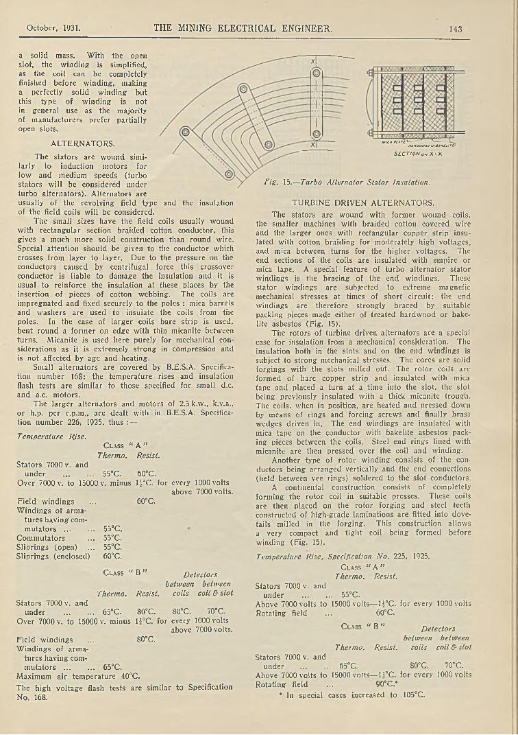
October, 1931. THE MINING ELECTRICAL ENGINEER. 143
a solid mass. With the open
slot, the winding is simplified,as the coil can be completely finished before winding, making a perfectly solid winding butthis type of winding is notin general use as the majority of manufacturers prefer partially open slots.
ALTERNATORS.
The stators are wound similarly to induction motors for
low and medium speeds (turbo stators will be considered under
turbo alternators). Alternators areusually of the revolving field type and the insulation of the field coils will be considered.
The small sizes have the field coils usually wound with rectangular section braided cotton conductor, this gives a much more solid construction than round wire. Special attention should be given to the conductor which crosses from layer to layer. Due to the pressure on the conductors caused by centrifugal force this crossover conductor is liable to damage the insulation and it isusual to reinforce the insulation at these places by the insertion of pieces of cotton webbing. The coils areimpregnated and fixed securely to the poles : mica barrels and washers are used to insulate the coils from thepoles. In the case of larger coils bare strip is used, bent round a former on edge with thin micanite between turns. Micanite is used here purely for mechanical considerations as it is extremely strong in compression and is not affected by age and heating.
Small alternators are covered by B.E.S.A. Specification number 168: the temperature rises and insulationflash tests are similar to those specified for small d.c. and a.c. motors.
The larger alternators and motors of 2.5 k.w., k.v.a., or h.p. per r.p.m., are dealt with in B.E.S.A. Specifica
tion number 226, 1925, thus :—
Temperature Rise.C l a s s “ A ”
Thermo. Resist.
Stators 7000 v. andunder ............. 55°C. 60°C.
Over 7000 v. to 15000 v. minus li°C. for every 1000 voltsabove 7000 volts.
Field windings ... 60°C.
Windings of armatures having com
mutators ............ 55°C.Commutators ... 55°C.Sliprings (open) ... 55°C.Siiprings (enclosed) 60°C.
C l a s s “ B ” Detectors
between between
Thermo. Resist. coils coil & slot
Stators 7000 v. andunder ............. 65°C. 80°C. 80°C. 70°C.
Over 7000 v. to 15000 v. minus li°C. for every 1000 voltsabove 7000 volts.
Field windings ... S0cC.Windings of arma
tures having commutators ............ 65°C.
Maximum air temperature 40°C.
The high voltage flash tests are similar to Specification
No. 168.
MIC» PL *TC *— 'V—---- V.HA *D tVOOO o» BA X t l > TE '
S E C T IO N o«i X - X
Fig. 15.— Turbo Alternator Stator Insulation.
TURBINE DRIVEN ALTERNATORS.
The stators are wound with former wound coils, the smaller machines with braided cotton covered wire and the larger ones with rectangular copper strip insulated with cotton braiding for moderately high voltages, and mica between turns for the higher voltages. The end sections of the coils are insulated with empire or mica tape. A special feature of turbo alternator stator windings is the bracing of the end windings. These stator windings are subjected to extreme magnetic mechanical stresses at times of short circuit; the end windings are therefore strongly braced by suitable packing pieces made either of treated hardwood or bake- lite asbestos (Fig. 15).
The rotors of turbine driven alternators are a special case for insulation from a mechanical consideration. The insulation both in the slots and on the end windings is subject to strong mechanical stresses. The cores are solid forgings with the slots milled out. The rotor coils are formed of bare copper strip and insulated with mica tape and placed a turn at a time into the slot, the slot being previously insulated with a thick micanite trough. The coils, when in position, are heated and pressed down by means of rings and forcing screws and finally brass wedges driven in. The end windings are insulated with mica tape on the conductor with bakelite asbestos packing pieces between the coils. Steel end rings lined with micanite are then pressed over the coil and winding.
Another type of rotor winding consists of the conductors being arranged vertically anti the end connections (held between vee rings) soldered to the slot conductors.
A continental construction consists of completely forming the rotor coil in suitable presses. These coils are then placed on the rotor forging and steel teeth constructed of high-grade laminations are fitted into dovetails milled in the forging. This construction allows a very compact and tight coil being formed before
winding (Fig. 15).
Temperature Rise, Specification No. 225, 1925.
C l a s s “ A ”Thermo. Resist.
Stators 7000 v. andunder .............. 55°C.
Above 7000 volts to 15000 volts— U°C. for every 1000 volts Rotating field ... 60°C.
C l a s s " B ” Detectors
between between Thermo. Resist. coils coil & slot
Stators 7000 v. andunder ... ... 65°C. 80°C. 70°C.
Above 7000 volts to 15000 volts— H°C. for every 1000 volts
Rotating field ... 90°C.*
* In special cases increased to 105°C.

144 THE MINING ELECTRICAL ENGINEER. October, 1931.
G— CLAMPING Ml NO
'sectorsr~^
M T Ft*s t » l a s t h Taa/hhc C o m
Ce*tovcro0 •¿'»•‘ I ' d c c . }$L*aEmAi*cTa*l -CDS'Thick P*e$***«*,• 04 RirTv***, '06&tTlAHti
H T COIL&AK£UTC OAAACL WOOO PACKINGon. overL TCOH.
e*K £U T C 6A**EL
O H DUCT
i rcoiLA A K IU T L BAHK£K O IL DUCT C O R £
H.7 CcHTKcCoui. Co* OV CTO A •y*-06" O t « . / C A T C A L L * * S ,f .C o T T Q i* T * A C P*ns**nn ‘Ot&ir Tv*ni/06ߣr.L*Tf*i
•IZBa k i u t l ß ***£ L
L - 7. C o n .Conducto* '2SZ~SD AC-C- C orron 3 m a/&£S>
Fig. 10.—Details of Transformer Insulation.
Flash Tests.
Stator : 1000 volts and twice rated voltage with a minimum of 2000 volts.
Rotor and Exciter : 10 times exciting voltage with minimum of 2000 volts, and maximum of 3500 volts.
TRANSFORMERS.
The insulation of transformers may be classified in three sections: core insulation; insulation betweenH. and L.T. windings and to earth; insulation between turns. General details are shewn in Fig. 16.
Core insulation consists of the insulation betweencore stampings, between core and clamping bolts and between core and clamping plates- In the case of transformers, this insulation is very important as many failures are due to heat set up by eddy currents in the core due to the failure of this insulation. The insulation between plates can consist of thin paper, varnish, or an oxide of iron formed by spraying the plates witha mixture of flour, chalk, and water. The core boltsand clamping plates are insulated from the core by bakelite tubes and washers.
The insulation between windings consists of press- pahn in the case of medium pressure transformers but for H.T. and E.H.T., bakelite tubes are generally used.
The insulation between turns, in L.T. windings,usually consists of double cotton covering on the wire. In the case of heavy current windings, a number oi small separately insulated conductors are used in parallel in order to reduce the eddy current losses in the conductor. These parallel wires are taped together to keep them in position for winding. The core is built up and circular coils are invariably used as they are cheaper to wind. Well impregnated hardwood is used for packing pieces. A bakelite sleeve is then placed over the laminations. The low tension winding, consisting of one, two, or more spiral coils, is then placed over the bakelite sleeve. It the case of two or more L.T. coils, bakelite or hardwood spacers are fitted between coils to provide a duct for oil circulation.
After completing the L.T. winding, more spacers and bakelite sleeves are fitted, each with an oil duct
between. The H.T. winding is then placed on the sleeve: with H.T. and E.H.T. windings, the coils are wound in section. A number of transformer failures have occurred due to failure of the insulation between turns, principally those turns close to the line terminals. These failures have been due to the concentration of voltage on these end turns when switching the transformer on to the supply or due to external disturbances. For this reason, the end turns (about 5°/o of the whole) have the insulation strengthened between turns. In the case of delta connected transformers this additional insulation is placed at both ends of the winding. The turns at tapping coils are also reinforced between turns.
No. 171.
Temperature Rise.
Transformers are dealt with in B.E.S.A. Specification The temperature rises are as follows :
By Resistance
Winding Class Class “ A ” “ B »
Oil
ByThermometer
55°C.
55°C.
Naturally and artificially air cooled ..............
Oil-immersed ..............
Oil-immersed forced water or oil (water cooled) 65°C.
The maximum air temperature 40°C. and water temperature 25°C.
75°C.
55°C.
65°C.
50°C.
50°C.
H.T. Test Voltages from a separate source.
The test voltage shall be 1000 plus twice the service voltage with a minimum of 2000 volts. In the case of single phase transformers to work on a system with one line earthed, the test voltage shall be 1000 plus 2.73 times the service voltage, and for two-phase with a common terminal, the test voltage shall be increased 40°/o. In the case of two-phase, the service voltage shall be taken as that of each separate phase.
Induced Voltage Test.
For windings not connected to earth : twice the service voltage. For windings where one point is connected to earth : 2.73 times the service voltage.
NORTH-EAST COAST
E.T.B.I. ANNUAL BALL.
Under the auspices of the Electrical Trades Benevolent Institution, the 13th Annual Ball will be held in Newcastle-on-Tyne on Friday, 27th November, in the Grand Assembly Rooms, Barras Bridge. Mr. R. P. Sloan, the newly-elected President of the North-East Coast Section of the Institution, has kindly consented to receive the guests. Mr. Sloan is very well-known as Chairman of the Newcastle-upon-Tyne Electric Supply Company Limited, and the Section is particularly fortunate in having him as its president.
It is , very gratifying to be able to record the popularity of this annual event in the North, which is the means of raising considerable sums for the Institution Funds, to enable it to carry on its very worthy and important work. Members of the Industry are asked to mark the date, and to note that tickets may be obtained from the Dance Secretary, Mr. F. W. Page, of
the British Thomson-Houston Company Limited, Pilgrim Street, Newcastle-on-Tyne.
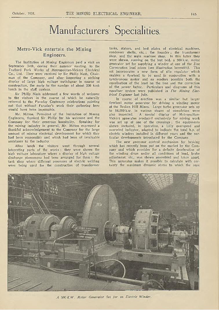
October, 1931. THE MINING ELECTRICAL ENGINEER. 145
Manufacturers Specialities.
Metro-Vick entertain the Mining
Engineers.
The Institution of Mining Engineers paid a visit on September 24th, during their summer meeting, to the Trafford Park Works of Metropolitan-Vickers Electrical Co., Ltd. They were received by Sir Philip Nash, Chairman of the Company, and after inspecting a striking display of large high voltage switchgear in course of construction, the party to the number of about 200 took lunch in the staff canteen.
Sir Philip Nash addressed a few words of welcome to the visitors in the course of which he naturally referred to the Faraday Centenary celebrations pointing out that without Faraday’s work their gathering here
would have been impossible.
Mr. Mitton, President of the Institution of Mining Engineers, thanked Sir Philip for his welcome and the
Company for their generous hospitality. Speaking for the mining industry in general, Mr. Mitton expressed a thankful acknowledgement to the Company for the large amount of mining electrical development for which they had been responsible and which had been of invaluable assistance to the industry.
After lunch the visitors went through several interesting parts of the works ; they were shewn the high voltage laboratory where a display of high voltage discharge phenomena had been arranged for them ; the tank shop where different processes of electric welding were being used for the construction of transformer
tanks, stators, and bed plates of electrical machines, condenser shells, etc. ; the foundry ; the transformer shop, and the main machine shop. In this latter they were shewn, running on the test bed, a 500 k.w. motor generator set for supplying a winder at one of the Zinc Corporation lead mines (see illustration herewith)'. This set incorporates a new form of slip regulator which enables a flywheel to be used in conjunction with a synchronous motor and so renders possible both the equalisation of the load on the line and the correction of the power factor. Particulars and diagrams of this equaliser system were published in The Mining Electrical Engineer last July.
In course of erection was a similar but larger flywheel motor generator for driving a winding motor at the Broken Hill Mines. Large turbo generator sets up to 64,000 k.w. in various stages of completion were also inspected. A special display of Metropolitan- Vickers apparatus produced exclusively for mining work was set up at one of the crossings ; the equipments shewn included, in operation, a Lilly overspeed and overwind indicator, adapted to indicate the total h.p. of electric winders installed in different years and the particular developments introduced by the Company.
The new governor control mechanism for braking which has recently been put on the market by the Company and which provides for a definite deceleration of the winding drum under all conditions of load, brake adjustment, etc., was shewn assembled and taken apart. This apparatus makes it possible to calculate with certainty the maximum dynamic stress to which the rope
A 500 K-W. Motor Generator Set for an Electric Winder.

146 THE MINING ELECTRICAL ENGINEER. October, 1931.
will be subjected ; such a calculation had hitherto been impossible.
A large size liquid controller with sector shaped
tanks, enabling a very large range of resistance to be obtained, this feature being of particular value when reverse current braking is adopted, was shewn opened up and with the servo motor for operating it by its side.
There was also 011 view here a self-contained geared turbo generator set complete, the condenser and all accessories being fixed on the floor level making the set both inexpensive and easy to install, and providing a cheap and convenient means of obtaining power for mines and factories when a public supply is not available.
The north gallery of the main shop through which
the visitors also passed, contained examples of flameproof switch and control gear manufactured specially for use in mines. There was also an exhibition of Cosmos lamps which included bulbs for miners’ lamps. A set of control gear for an electric train was shewn in operation.
Steel Arch and Prop Clip.
The use of steel arching underground has introduced the difficulty of attaching to the steel arch the necessary
underground equipment such as electric power and lighting cables, signal and telephone wires, compressed airand steam pipes, lighting fittings, etc. Bands or strapsare effective only to a degree ; they are extremely clumsy and expensive, and waste a considerable amount of time in fixing and transferring. The Thor Clip, introduced by Haslam and Stretton Ltd. some two years ago has beenaltogether successful and is extensively used. Practice,however, revealed that though good there was room for improvement. It had the disadvantage of requiring a key as well as a carrier. One of the largest users of steel arching in this country who also used thousands of Thor Clips has overcome this difficulty and, as a result, the “ A llgrip” clip has “ arrived.” The new clip is not in separate two or three pieces, but it is a threepiece clip, combined in such a way that none of theparts can be detached from each other. The advantage of this in time and expense will be apparent. The three parts comprise a pair of sliding clips and a cottor or stem, which is threaded through the sliding clips. The
stem is the carrying agent, the bottom being formed in the particular manner as required, while the top end is
turned over to form a driving head as well as pre
venting the separation of theparts. The principle of thedesign will be gathered from the illustration : it will benoticed that the more weight or force imposed on the clip, the tighter the grip becomes.
The clips have wide scope
for underground use, and can be adapted for carrying power and lighting cables,
signal wires, compressed air and water pipes wherever steel arches are used in road
ways underground. Where steel arches are filled in between with concrete or
brickwork, so long as the flange is slightly exposed, the clip will grip it. Steel arch
An “ Allgrip ” Clip. roadways underground can
be scaffolded for repair, quickly and with safety ; in fact, the clips can be adapted for any purpose that requires attachment to the steel arches. For withdrawing steel arches which have become embedded in the ground, this device, made in a much stouter form, can be attached to the foot of the steel arch in the reverse position, then by the simple means of a lever, the arch can be prised up. These clips can also be used for all classes of structural steelwork for securing temporary scaffolding or any other apparatus used during erection, and can be adapted to fit any rolled steel joist, channel or angle section.
Coal Face Machinery Exhibition :
Sheffield : 2nd—10th October, 1931.
(1Continued, from page 116.)
COW USHER WALKER & Co.
A particular feature of the Senior Longwall Chain Coalcutter is a slewing device by which the jib is swung round under the coal by means of totally enclosed gears and when it arrives at the cutting position it is automatically stopped. This eliminates the use of the haulage rope for jibbing in, and is claimed to give a considerable saving in time as well as longer life for the rope. For re-picking, the jib may be quickly siwung out, the picks changed and the jib swung back into position again, thus saving time and wear and tear of switch contacts. This slewing device is said to be superior for cutting out corners and also to increase safety, for if the operator should neglect to attend to the machine when jibbing in, no harm can be done
Another particular point of this machine is that the direction of rotation of the haulage drum can be reversed when in the flitting speed, thus allowing the operator to let out the rope without having to pull at it. The machine is built up in three units, consisting of Gear- head, Motor (Electric or Compressed Air), and Haulage End. Ball or Roller Bearings are fitted throughout, and special alloy steels are tned to ensure long life for the working parts.
The C. W. Junior Longwall Chain Coalcutter is generally similar to the foregoing excepting that in this case the jib is slewed under the coal by means of the rope. It is designed to work in thin and highly inclined seams ; the height of the machine being 12V inches.
Another C. W. coalcutter is the Chain Arc Header designed for cutting headings up to 19 ft. wide and suitable for gradients as steep as 1 in 2}. For such heavy gradients a positive rope drum is provided with safety brake and drag. It is fitted with the same special slewing device as is used in the C. W. Senior longwall machine : the importance of a device which automatically stops the feed is very evident when used in conjunction with an arc header. There are no chains or ropes used for operating the slewing mechanism and the whole of the gearing is entirely enclosed. The motor may be switched on and off from either end of the machine and all controls can be operated by one man. To facilitate the negotiation of bad ground or curves, a special slow
speed is also fitted.
CdJLLICK Ltd.
Of particular interest on this stand were the flameproof electric drills. One of these is designed especially for use in collieries and complies with the C.M. Regulations in every respect. The motor housing is capable

October, 1931. THE MINING ELECTRICAL ENGINEER. 147
of taking either an a.c. or d.c. motor and in both cases a current of air is driven around the inner casing of the motor by means of a fan to ensure cool running. The power is transmitted, through three sets of gears running in ball bearings, to the feed bar. By means of a split nut held in position by a clutch, the drill which is fitted into the end of the feed bar is fed into the coal at speeds varying from 15 ins. to 2S ins. per minute. The machine
is capable of drilling the hardest coal with ease
The other electric drill is for stone working. It is similar to the coal drill, except that the gears are reduced to give a slower forward feed and the stand on which the motor assembly is fixed is not fitted with a skid or base plate, thus enabling the stand to be set either vertical or horizontal, or any point in between.
BRITISH JEFFREY-DIAMOND Ltd.
Several examples of the B.J.D. Coalcutters were exhibited. Important modifications have recently been introduced and following successful practical results the improvements have been standardised in these machines. A step forward is the substitution of plain bush bearings with high-class roller bush bearings on the intermediate anti main sprocket driving shafts. Ball journal and thrust bearings are also incorporated in conjunction with these roller bush bearings to cater for the various thrusts which are set up under heavy cutting. Power consumption is thereby reduced and the general efficiency considerably improved. There is a marked ease and smoothness of running, with a decrease in upkeep costs and prolongation of the life of the various component units.
High pressure grease gun lubrication is arranged, and readily accessible grease caps, suitably protected by covers, are provided for greasing purposes : it is only necessary to use the grease gun say twice per shift. A difficulty experienced with the older oil lubricated machine was the tendency, once bearings became worn, for the oil to be lost as the machine travelled across the face. This lias been overcome by the use of special grease which maintains its nature even at high temperatures. This grease, which is introduced into the
gear case, is additional to the high pressure grease gun lubrication for the shafts and bearings. A further precaution has been introduced to make the gear casepractically oil tight, in the event of an inferior kind of grease being used which may tend to liquify at high temperature, a special oil retaining pad being fitted in the sprocket mounting. All heavy duty shafts are machined square at the ends instead of being keywayed and the gears are suitably broached to fit square necks.
The jib fitted to this improved chain coalcutter is of the type having solid top and bottom plates, withsturdy centre support bar, giving an exceptionally strong construction. The arrangement of the cutting unit is such as to make it possible readily to arrange the machine to cut either at floor level or dead floor level, i.e., withsledge plate extending under the cutting or cut shortjust behind the driving motor.
An improvement which is particularly noteworthy on this portion of the machine is in connection with the haulage speed controls. The variation of haulage speed is obtained by varying the number of teeth in engagement of the ratchet. Previously, this variation was obtained through a disc rotated by hand. A link motion positively operated and with separate definite locating positions is now provided.
The a.c. electric motor is of the one piece stator frame construction which dispenses with the use of removable covers. It is fully watertight and flame-proof. For d.c. work the motor is of patented type and is cumulative compound wound. Both types of motor comply fully with official regulations. The British Standard Cable Plug and Adaptor Box is now incorporated as standard.
Public Works, Roads and Transport.
The Public Works, Roads and Transport Congress Exhibition is to be held at the Royal Agricultural Hall from November 16th to 21st, 1931, under the patronage
of His Majesty the King. There are more than 200 names on the list of exhibitors. All the available area at
i
An interesting “ mining electrical” corner of the Coal Face Machinery Exhibition.
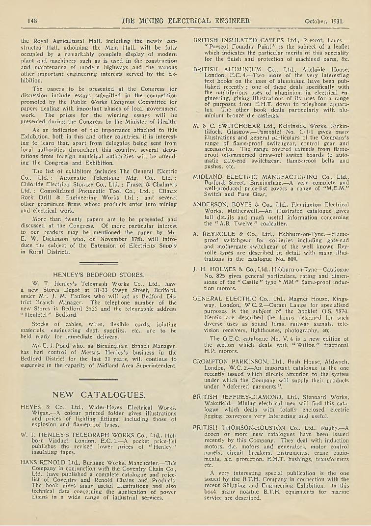
148 THE MINING ELECTRICAL ENGINEER. October, 1931.
the Royal Agricultural Hall, including the newly constructed Hall, adjoining the Main Hall, will be fully occupied by a remarkably complete display of modern plant and machinery such as is used in the construction and maintenance of modern highways and the various other important engineering interests served by the Exhibition.
The papers to be presented at the Congress for discussion include essays submitted in the competition promoted by the Public Works Congress Committee for papers dealing with important phases of local government work. The prizes for the winning essays will be presented during the Congress by the Minister of Health.
As an indication of the importance attached to this Exhibition, both in this and other countries, it is interest
ing to learn that, apart from delegates being sent from local authorities throughout this country, several deputations from foreign municipal authorities will be attending the Congress and Exhibition.
The list of exhibitors includes The General Electric Co., Ltd. ; Automatic Telephone Mfg. Co., Ltd. ; Chloride Electrical Storage Co., Ltd. : Fraser & Chalmers Ltd. ; Consolidated Pneumatic Tool Co., Ltd. ; Climax Rock Drill & Engineering Works Ltd. ; and several other prominent firms whose products enter into mining and electrical work.
More than twenty papers are to be presented and discussed at the Congress. Of more particular interest
to our readers may be mentioned the paper by Mr.E. W. Dickinson who, on November 17th, will introduce the subject of the Extension of Electricity Supply in Rural Districts.
HENLEY’S BEDFORD STORES.
W. T. Henley’s Telegraph Works Co., Ltd., have a new Stores Depot at 31-33 Gwyn Street, Bedford, under Mr. J. M. Faulkes who will act as Bedford District Branch Manager. The telephone number of the new Stores is Bedford 3566 and the telegraphic address “ Henletcl ” Bedford.
Stocks of cablcs, wires, flexible cords, jointing materials, engineering dept, supplies, etc., are to be held ready for immediate delivery.
Mr. E. J. Pond who, as Birmingham Branch Manager, has had control of Messrs. Henley’s business in the Bedford District for the last 31 years, will continue to supervise in the capacity of Midland Area Superintendent.
NEW CATALOGUES.
HEYES & Co., Ltd., Water-Heyes Electrical Works, Wigan.—A colour printed folder gives illustrations and prices of lighting fittings, including those of explosion and flameproof types.
W. T. HENLEY’S TELEGRAPH WORKS Co., Ltd., Hol- born Viaduct, London, E.C. 1.—A pocket price-list publishes the revised lower prices of “ Henley ” insulating tapes.
HANS RENOLD Ltd., Burnage Works. Manchester.—This Company in conjunction with the Coventry Chain Co., Ltd., have published a complete catalogue and pricelist of Coventry and Renold Chains and Products. The book gives many useful illustrations and also technical data concerning the application of power chains in a wide range of industrial services.
BRITISH INSULATED CABLES Ltd., Prescot, Lancs.— “ Prescot Foundry Paint” is the subject of a leaflet which indicates the particular merits of this speciality for the finish and protection of machined parts, &c.
BRITISH ALUMINIUM Co., Ltd., Adelaide House, London, E.C. 4.— Two more of the very interesting text books on the uses of aluminium have been published recently ; one of these deals specifically with the multifarious uses of aluminium in electrical engineering, giving illustrations of its uses for a range of purposes from E.H.T. down to telephone apparatus. The other book deals particularly with aluminium bronze die castings.
M. & C. SWITCHGEAR Ltd., Kelvinside Works, Kirkintilloch, Glasgow.— Pamphlet No. C/1/1 gives many illustrations and general particulars of the Company’s range of flame-proof switchgear, control gear and accessories. The range covered extends from flameproof oil-immersed draw-out switch boards to automatic gate-end switchgear, flame-proof bells and pushes, etc.
MIDLAND ELECTRIC MANUFACTURING Co., Ltd., Barford Street, Birmingham.— A very complete and well-produced price-list covers a range of “M.E.M.” Switch and Fuse Gear.
ANDERSON, BOYES & Co., Ltd., Flemington Electrical Works, Motherwell.— An illustrated catalogue gives full details and much useful information concerning the “ A.B. Twelve” coalcutter.
A. REYROLLE & Co., Ltd., Hebburn-on-Tyne.— Flameproof switchgear for collieries including gate-end and mothergate switchgear of the well known Rey- rolle types are described in detail with many illustrations in the catalogue No. 809.
J. H. HOLMES 8= Co., Ltd., Hebburn-on-Tyne— Catalogue No. 825 gives general particulars, rating and dimensions of the “ Castle ” type “ MM ” flame-proof induction motors.
GENERAL ELECTRIC Co., Ltd., Magnet House, Kings- way, London, W.C. 2.—Osram Lamps for specialised purposes is the subject of the booklet O.S. 5870. Herein are described the lamps designed for such diverse uses as sound films, railway signals, television receivers, lighthouses, photography, etc.
The G.E.C. catalogue No. V. 4 is a new edition of the section which deals with “ Witton ” fractional H.P. motors.
CROMPTON PARKINSON, Ltd., Bush House, Aldwych, London, W.C. 2.—An important catalogue is the one recently issued which directs attention to the system under which the Company will supply their products under “ deferred payments ”.
BRITISH JEFFREY-DIAMOND, Ltd., Stennard Works, Wakefield.— Mining electrical men will find this catalogue which deals with totally enclosed electric jigging conveyors very interesting and useful.
BRITISH THOMSON-HOUSTON Co., Ltd.. Rugby.— A dozen or more new catalogues have been issued recently by this Company. They deal with induction motors, d.c. motors and generators, motor control panels, circuit breakers, instruments, crane equipments, a.c. protection, E.H.T. bushings, transformers etc.
A very interesting special publication is the one issued by the B.T.H. Company in connection with the recent Shipping and Engineering Exhibition. In this book many notable B.T.H. equipments for marine service are described.