the calculation and research on mbr simulation …
TRANSCRIPT

Original Research Paper
1 1 1*Xiaohan SUN , Chunqing Li , Xiangning Chen1 School of Computer Science and Technology, Tianjin Polytechnic University, Tianjin 300387,China. *Corresponding Author
THE CALCULATION AND RESEARCH ON MBR SIMULATION BASED ON CFD
1. INTRODUCTION:Membrane bioreactor (MBR) is a new wastewater treatment process that com-bines biofilm technology with traditional wastewater treatment technology. MBR has the characteristics of high degree of purification, high degree of equip-ment integration, and high volumetric load. It has a small footprint, good auto-mation control and low residual sludge production [1]. Brannock M designed a CFD model to explore the effects of ventilation and bio-nutrition on membrane bioreactors [2]. Amini E studied the hydrodynamic properties of shear stress, cross-flow velocity and membrane fouling resistance in membrane bioreactors. Through relevant CFD simulation experiments, the fluid flow, shear stress and cross flow velocity of different mixture concentrations were explored. Experi-mental results showed that the outermost membrane is more prone to scale for-mation due to small shear force [3].
Some researches on Computational Fluid Dynamics (CFD) at home and abroad summarize the main factors of membrane fouling formation from membrane fouling factors, operating parameters and membrane materials [4]. Through the numerical simulation to solve the membrane reaction process, this way of solv-ing the problem has attracted the attention of many researchers [5]. The loading density of the flat membrane module was simulated and optimized, and the pack-ing density could be increased by 40% on the original basis [6]. Wang Y studied the hydrodynamic behavior of full-size immersed MBR by using a porous medium model coupled with a three-dimensional multiphase model [7]. By com-paring the liquid flow rate and dissolved oxygen with the laboratory-sized immersion MBR reactor, it is concluded that the sludge concentration has a rela-tively large impact on the experiment [8-9]. The CFD is applied from the fluid mechanics of MBR, and the simulation experiments are carried out by setting rel-evant parameters to better understand the hydrodynamic behavior of sewage in membrane bioreactor. The computational fluid dynamics method can be used to study the hydraulic parameters of the gas-lift cycle split membrane bioreactor, and related simulation, optimization and sensitivity analysis [10].
In this paper, ANSYS FLUENT was used to complete the simulation experi-ment. The hollow fiber membrane was used as the membrane material, and the experimental data were referred to uf-4 type membrane components. The porous media model was applied to complete the simulation model calculation.
2. MEMBRANE MODULE MODEL:The model size is 100*100*100mm (the default arrangement is length*width*height). The cuboid in the center of the model is the water inlet. The size of the water inlet is 10*10*50mm. The two ends of the water inlet are provided with ten hollow fiber tubes perpendicular to the bottom surface and cut respectively, with the size of 0.55*0.55*3.14*50mm. The upper end of the hol-low fiber tube is sealed, and the lower end is the outlet. Its inner diameter is 0.6mm and the outer diameter is 1.1mm. The walls are surrounded by the top and bottom. The top and bottom of the model can be opened for easy removal of deposits and membrane cleaning. The three-dimensional rendering of the model is shown in Figure 1.
The membrane module data herein refers to the UOF-4 membrane module, and the parameters thereof are shown in Table 1.
Table 1: Parameters of the model design reference
3. CFD MODELING METHOD:Basic steps in computational fluid dynamics:
(1) For the problem under study, establish a relevant mathematical model, and at the same time determine the applied differential equations to describe the rele-vant hydrodynamic changes; (2) use the discretization method to map the contin-uous variables while making (1) The differential equations are transformed into algebraic equations; (3) the discrete positions of (2) are represented by meshing; (4) the initial conditions and boundary conditions of the model are determined; (5) the control parameters of the model are set; (6) Using a computer to solve dis-
Copyright© 2019, IEASRJ. This open-access article is published under the terms of the Creative Commons Attribution-NonCommercial 4.0 International License which permits Share (copy and redistribute the material in any medium or format) and Adapt (remix, transform, and build upon the material) under the Attribution-NonCommercial terms.
19International Educational Applied Scientific Research Journal (IEASRJ)
Computer Science Volume : 4 ¦ Issue : 5 ¦ May 2019 ¦ e-ISSN : 2456-5040
ABSTRACT
Membrane bioreactor (MBR) has been successfully applied to biological wastewater treatment, which solves the long-term problem of effective solid-liquid separation and separation. MBR optimization requires knowledge of membrane fouling, mixing, and biomechanics. The MBR is designed primarily for biodynamic and membrane fouling considerations, and fluid dynamics within the system is critical to the performance of the system. Computational fluid dynamics (CFD) provides a method for simulating and predicting MBR. In this paper, the simulation software (Ansys Fluent) was used to establish a membrane bioreactor model with hollow fiber as the membrane component, and the relationship between inlet velocity, height of membrane bioreactor and water yield was studied. The hollow fiber membrane filaments with vertical tangential arrangement were taken as the research object. By optimizing the MBR condition setting, it is concluded that when the inlet velocity and the height of the model are 1:20, the water production effect is the best and the water in the model is the least.
KEYWORDS: CFD; Computational fluid dynamics; MBR; Membrane bioreactor.
Figure 1: 3D rendering of the model
UOF-4 membrane module
Single hollow fiber membraneInner diameter 0.6mm,Outer diameter 1.1mm
Membrane material PVDF
Housing material UPVC
Membrane surface area 40m2
Maximum inlet pressure 0.3MPa
Maximum transmembrane pressure 0.15MPa
Operating temperature range 5~45℃
pH range pH 2~10
Pure water initial flux 6000~7000L/h

Original Research Paper
20 International Educational Applied Scientific Research Journal (IEASRJ)
crete equations; (7) using graphical software to display calculation results [11-12].
3.1. Porous media model:The porous media model approach considers the action of the solid structure in the flow region to be the distribution resistance attached to the fluid. The equa-tions and representative parameters are shown in Table 2.
Computational Fluid Mechanics Control Equation:
Table 2: Formula parameters
3.2. Boundary conditions:Boundary conditions are the most important design parameters for Fluent analy-sis. The specific types and examples are shown in Table 3 below. At the same time, boundary conditions can be divided into single-sided boundaries and dou-ble-sided boundaries. Common single-sided boundaries include axis bound-aries, free outflow boundaries and mass flow inlet boundaries. Common double-sided boundaries include fan boundaries, wall boundaries and so on.
Table 3: Types of boundary conditions and examples
4. CFD MODELING PROCESS:The modeling of the model was completed using the visual drawing software CATIA. The specific effect picture is shown in Figure 2. Then introduce ANSYS ICEM CFD for meshing. Figure 3 is a concrete meshing structure diagram.
In ICEM CFD, there are two types of meshing: structured meshing and unstruc-tured meshing. Structured meshing usually divides the geometric model into sev-eral quadrilaterals or hexahedrons; unstructured meshing usually divides the geo-metric model into several triangles or tetrahedrons. The specific method of parti-tioning depends on the actual situation. This experimental model adopts the com-bination of structural grid and unstructured grid. Twenty tubes were unstructured and applied with a porous media model; others were structured grids. According to relevant experience, this experiment assumes four sets of viscous drag coeffi-cient and inertial drag coefficient for testing. Table 4 shows the viscous resis-tance and inertial resistance test parameters. Comparing the experimental results, the viscous drag coefficient was 2.111e+12 and the inertia drag coeffi-cient was 44000. Then import Fluent, perform the relevant inspection grid, and perform the calculation of the experiment without any errors.
Table 4: Viscous resistance and inertia resistance test parameters
The number of meshes in this model is nearly 200,000, so the calculation time using Fluent is longer. Through the retrospective method, the influent speed is continuously adjusted. By analyzing the velocity distribution map and the pres-sure cloud map, the influent velocity is finally 5 mm/s. Under these conditions, the model produces better water production and less water is accumulated inside the model.
The result is shown below. Figure 4 is a flow rate distribution diagram of the experimental model. It can be seen that the flow rate at the top of the model is low, and for the hollow fiber tube portion, the water velocity at the bottom end is large. When the water rushes to the top cover, it falls down and completes the water. Figure 5 shows the distribution of the flow rate map of the model. When the calculation reaches convergence, it can be seen that the model can reasonably complete the filtration when the water intake is stable, and does not accumulate a large amount of water.
Set the number of iterations 500 times to start the calculation. After calculation, the residual curve and the outlet flow are shown in Fig. 6. From the experimental results, we can see that when the iteration is 30 times, the calculation reaches the convergence automatic stop calculation. Figure 7 is the grid quality map. From Figure 7, we can observe that the minimum side length of the block in the model is 0.7, so the mesh quality of the model is high, then save the grid file, prepare the solver for the solution and then save it. The file is ready for post processing.
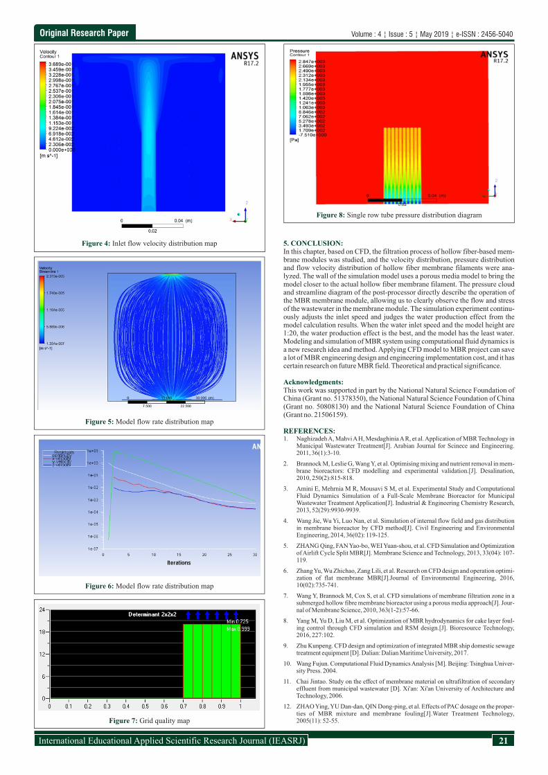
Fig. 8 is a pressure distribution diagram of a single-row tube. It can be seen from the analysis that the pressure at the upper part of the hollow fiber discharge tube is large due to the position problem of the water inlet, and is sequentially decreased from the top to the bottom. The bottom of the tube is caused as a water outlet and the pressure is small.
Volume : 4 ¦ Issue : 5 ¦ May 2019 ¦ e-ISSN : 2456-5040
Category Common use model
Import and export boundary conditions
pressure inlet, pressure outlet, speed inlet, air inlet, etc.
Wall condition wall, symmetry, cycle, axis
Internal unit area fluid, solid
Internal surface boundaryRadiator, long and short jump, wall,
internal interface
Figure 2: Experimental model structure
Figure 3: The graph of meshing result
Serial number Viscous drag coefficient Inertial drag coefficient
1 2.111e+09 4.4
2 2.111e+12 4.4
3 2.111e+12 440
4 2.111e+12 44000
Original Research Paper
21International Educational Applied Scientific Research Journal (IEASRJ)
5. CONCLUSION:In this chapter, based on CFD, the filtration process of hollow fiber-based mem-brane modules was studied, and the velocity distribution, pressure distribution and flow velocity distribution of hollow fiber membrane filaments were ana-lyzed. The wall of the simulation model uses a porous media model to bring the model closer to the actual hollow fiber membrane filament. The pressure cloud and streamline diagram of the post-processor directly describe the operation of the MBR membrane module, allowing us to clearly observe the flow and stress of the wastewater in the membrane module. The simulation experiment continu-ously adjusts the inlet speed and judges the water production effect from the model calculation results. When the water inlet speed and the model height are 1:20, the water production effect is the best, and the model has the least water. Modeling and simulation of MBR system using computational fluid dynamics is a new research idea and method. Applying CFD model to MBR project can save a lot of MBR engineering design and engineering implementation cost, and it has certain research on future MBR field. Theoretical and practical significance.
Acknowledgments:This work was supported in part by the National Natural Science Foundation of China (Grant no. 51378350), the National Natural Science Foundation of China (Grant no. 50808130) and the National Natural Science Foundation of China (Grant no. 21506159).
REFERENCES:1. Naghizadeh A, Mahvi A H, Mesdaghinia A R, et al. Application of MBR Technology in
Municipal Wastewater Treatment[J]. Arabian Journal for Scinece and Engineering. 2011, 36(1):3-10.
2. Brannock M, Leslie G, Wang Y, et al. Optimising mixing and nutrient removal in mem-brane bioreactors: CFD modelling and experimental validation.[J]. Desalination, 2010, 250(2):815-818.
3. Amini E, Mehrnia M R, Mousavi S M, et al. Experimental Study and Computational Fluid Dynamics Simulation of a Full-Scale Membrane Bioreactor for Municipal Wastewater Treatment Application[J]. Industrial & Engineering Chemistry Research, 2013, 52(29):9930-9939.
4. Wang Jie, Wu Yi, Luo Nan, et al. Simulation of internal flow field and gas distribution in membrane bioreactor by CFD method[J]. Civil Engineering and Environmental Engineering, 2014, 36(02): 119-125.
5. ZHANG Qing, FAN Yao-bo, WEI Yuan-shou, et al. CFD Simulation and Optimization of Airlift Cycle Split MBR[J]. Membrane Science and Technology, 2013, 33(04): 107-119.
6. Zhang Yu, Wu Zhichao, Zang Lili, et al. Research on CFD design and operation optimi-zation of flat membrane MBR[J].Journal of Environmental Engineering, 2016, 10(02):735-741.
7. Wang Y, Brannock M, Cox S, et al. CFD simulations of membrane filtration zone in a submerged hollow fibre membrane bioreactor using a porous media approach[J]. Jour-nal of Membrane Science, 2010, 363(1-2):57-66.
8. Yang M, Yu D, Liu M, et al. Optimization of MBR hydrodynamics for cake layer foul-ing control through CFD simulation and RSM design.[J]. Bioresource Technology, 2016, 227:102.
9. Zhu Kunpeng. CFD design and optimization of integrated MBR ship domestic sewage treatment equipment [D]. Dalian: Dalian Maritime University, 2017.
10. Wang Fujun. Computational Fluid Dynamics Analysis [M]. Beijing: Tsinghua Univer-sity Press. 2004.
11. Chai Jintao. Study on the effect of membrane material on ultrafiltration of secondary effluent from municipal wastewater [D]. Xi'an: Xi'an University of Architecture and Technology, 2006.
12. ZHAO Ying, YU Dan-dan, QIN Dong-ping, et al. Effects of PAC dosage on the proper-ties of MBR mixture and membrane fouling[J].Water Treatment Technology, 2005(11): 52-55.
Volume : 4 ¦ Issue : 5 ¦ May 2019 ¦ e-ISSN : 2456-5040
Figure 4: Inlet flow velocity distribution map
Figure 5: Model flow rate distribution map
Figure 6: Model flow rate distribution map
Figure 7: Grid quality map
Figure 8: Single row tube pressure distribution diagram