the channel multiplier cathode-ray tube - … bound... · the channel multiplier cathode-ray tube...
TRANSCRIPT
Philips J. Res. 41, 325-342, 1986 R1J33
THE CHANNEL MULTIPLIER CATHODE-RAY TUBE
by A. W. WOODHEAD, D. WASHINGTON, D. L. LAMPORT,A. G. KNAPP, J. R. MANSELL and K. G. FREEMAN .
Philips Research Laboratories, RedhilI Surrey RH J 5HA, England
AbstractThis paper describes a new approach to cathode-ray tube design aimed atachieving a significant depth reduction. The addressing function of the elec-tron beam has been separated from the light generation process by a chan-nel electron multiplier array, allowing the use of a novel deflection systembased on a low-power scanning beam. Monochrome versions of the thintube have been made with a 12" (305 mm) picture diagonal and a front-to-back depth of only 75 mm. Methods of introducing colour to the displayare described, and time-sequential systems for sharing the single beambetween the three primary colours are discussed.PACS numbers: 85.10.-n and 85.60.Pg.
1. IntroduetionThe last decade has seen an explosion not only in the amount of information
available, but also in the proportion of that information that is brought to usby electronic means. Traditionally the cathode-ray tube (CRT) is the mostcommon electronic display device but over the last two decades there has beena rapid development in alternative approaches. Some of these have helped tocreate entirely new products. The digital watch and the pocket calculator areonly practical because of the advent of new displays. Generally, these findtheir way into applications which, for one reason or another, the cathode-raytube cannot satisfy. New displays are beginning to encroach on the fringes ofthe territory traditionally seen as the preserve of the CRT, despite its advan-tages of high information content, brightness, colour, ease of addressing andlow cost. The features which enable them to compete with the CRT, are thatthey are thin, light-weight, operate at low voltage and in some examples. con-sume very little power. Anticipating this competition the channel multiplierCRT concept was developed with the aim of reducing the depth of the tubeand also its power requirements.To begin to tackle these problems it is useful to discover the factors which
together determine the more or less universal shape of the traditional tube.The essential feature of the cathode-ray tube, as its name implies, is a beam of
Phllips Journalof Research Vol. 41 No.3 1986 325'----~. ~~---
A. W. Woodhead et al.
electrons which is deflected in two dimensions to define the picture, modulatedin intensity to give a range of grey levels and finally, by impact with a fluores-cent screen produces the light that conveys the information to the observer.
This latter process requires a few watts of power. In a conventional CRTthis power is produced by using a screen current' of the order of 100 JlA with ascreen voltage of 10 to 25 kV, to keep the beam focussed into a small spot.Deflection of high energy beams whilst maintaining a good spot size, becomesincreasingly difficult and power-consuming as the deflection angle increases.Thus, the optimum arrangement is with the gun mounted at right angles to thescreen to minimize the deflection angle. The resulting tube has a depth roughlyequal to the picture height.
In the channel multiplier CRT the addressing function of the electron beamhas been separated from the light-generating process by a two-dimensionalelectron multiplier. The electron beam is then of a low voltage and low currentand can, therefore be easily deflected through large angles in a complex systemwithout undue enlargement of the spot. The electron multiplier is situatedclose to the fluorescent screen and amplifies the beam current. The amplifiedcurrent, on leaving the multiplier, is accelerated across a short gap to thescreen to produce the power necessary to generate the light output. The flexi-bility that this arrangement gives in the tube design results in much shallowertubes that require less scanning power.
2. The channel multiplier
The separation of the beam-addressing and picture-display functions isachieved by means of a planar assembly of minute electron multipliers. Thismultiplier array must satisfy three primary requirements. Firstly, it must en-sure that there is no interaction between the low-energy scanning beam andthe high-power output beam. Secondly, it must provide sufficient amplifica-tion of the low-current scanning beam and finally, it must contain enoughamplifying channels so there are sufficient picture points to satisfy the applica-tion. In addition there are several important secondary requirements. Thegain must be uniform over the whole area and the peak output current must besufficient to satisfy the display brightness requirements. The multiplier mustnot be too difficult to make and of course, must have an adequate life-time.
The scanning section of the tube operates with a beam energy of a fewhundred electron-voltsj.this sets a beam current limit of about one !lA in orderto avoid spot blow-up due to space charge. The output current is determinedby the display brightness requirement and, for screen acceleration potentialsof 10 to 15 kV, will be usually ~ fraction of a mA. Hence, the multiplier needsto have a gain factor of several hundreds. Itmust also contain enough multi-
326 Phillps Journalof Research Vol.41 No.3 1986

The channel multipier CRT
plying elements to provide adequate picture information; for television usethis will typically range from 150.000 to 300.000.
Two types of large-area electron multiplier can be made to meet theserequirements. One was originally developed for high-resolution image intensi-fier applications and consists of a fused array of hollow glass fibres 1) as shownin fig. 1. Each of these hollow fibres can be as small as 10 urn in diameter, andcan provide an electron gain of 1000 or more by means of a cascade process
+ 300V
+ 600V
+ 900V
+1200V
+1500V
Channels
Fig. 1. Glass channel plate.
Electron trajectory
91300llmsmall hale
i4--lol---S/l .. 420llmlarge hale
Fig.2. Metal dynode multiplier.
Ph1l1ps Journal of Research Vol. 41 No.3 1986 327
A. W. Woodhead et al.
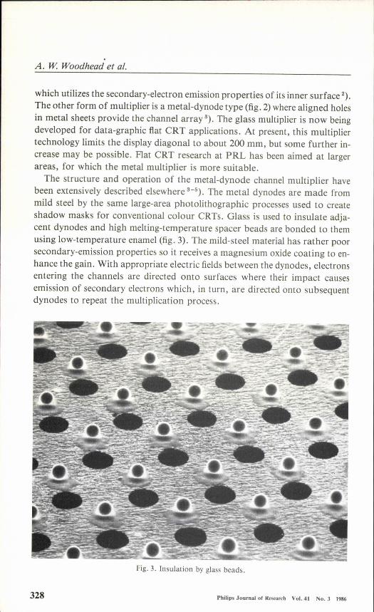
which utilizes the secondary-electron emission properties of its inner surface 2).The other form of multiplier is a metal-dynode type (fig. 2) where aligned holesin metal sheets provide the channel array 3). The glass multiplier is now beingdeveloped for data-graphic fiat CRT applications. At present, this multipliertechnology limits the display diagonal to about 200 mm, but some further in-crease may be possible. Flat CRT research at PRL has been aimed at largerareas, for which the metal multiplier is more suitable.The structure and operation of the metal-dynode channel multiplier have
been extensively described elsewhere 3-5). The metal dynodes are made frommild steel by the same large-area photolithographic processes used to createshadow masks for conventional colour CRTs. Glass is used to insulate adja-cent dynodes and high melting-temperature spaeer beads are bonded to themusing low-temperature enamel (fig. 3). The mild-steel material has rather poorsecondary-emission properties so it receives a magnesium oxide coating to en-hance the gain. With appropriate electric fields between the dynodes, electronsentering the channels are directed onto surfaces where their impact causesemission of secondary electrons which, in turn, are directed onto subsequentdynodes to repeat the multiplication process.
328 Philips Journalof Research Vol. 41 No.3 1986
Fig. 3. Insulation by glass beads.
The channel multipier CRT
The multiplier used for the experimental 12" CRT described in this paperhas a full 305 mm display diagonal. The aligned holes are arranged in deltaformat with a spacing between centres of 0.55 mm, giving a total of approxi-mately 170.000 channels. With a potential difference of 300 V between adja-cent dynodes, stage gain values are in the range 3-3.3. The overall gain alsodepends upon the collection efficiency of the first dynode, as the multiplyingarea of the channels comprises only some 250/0 of the total surface exposed tothe incoming electrons. In practice a beam amplification of several hundredtimes is achieved using seven multiplying stages. In theory it should be pos-sible to reduce the number of dynodes by operating with higher inter-stagevoltages. Increasing the inter-stage electron energy raises the secondary-emis-sion coefficient, but it also introduces the risk of spontaneous electron emis-sion within the channels, especially where unwanted foreign particles causelocal disturbance to the electric field. Seven stages at 300V per. stage provide asuitable compromise for the present research phase of this activity. The rela-tionship between output and input current is linear up to outputs of at least1mA per channel, which is more than' enough for most video and data-graphicapplications; at higher values there is some suppression of the secondary emis-sion in the last dynode due to space charge. Spatial gain uniformity is alsoacceptable. A variation over the whole multiplier of less than ± 4%, reducingto below ± 0.5% over distances of 1 cm or less; has been achieved.
A longer' term consideration when introducing a new component into avacuum display tube, is the question of life-time, and in the channel multiplierCRT this is determined by ageing effects of the secondary emitter. The quality-of the vacuum ambient is important; methane and other hydrocarbons de-compose under electron bombardment to deposit carbon contaminants whichdepress the gain. By suitable choice of getter and tube processing techniques,such effects can be eliminated. Constant gain has been demonstrated in sealed-off tubes over thousands of hours of continuous operation.
3. The thin cathode-ray tubeThe depth and volume of the cathode-ray tube can be reduced considerably
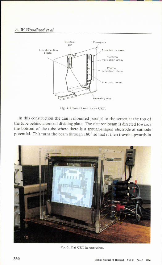
if the electron gun is positioned parallel to the screen rather than in the usualorthogonal position. In taking advantage of the low-energy scanning beam ofthe channel multiplier CRT to achieve this reduction in depth, it is importantparticularly for large displays, that the picture should occupy the maximumpossible fraction of the total frontal area. A number of designs for thin Ck'I'shave been proposed with the gun placed to one side of the screen 6-8) but the'folded design shown in fig. 4 combines the features of depth reduction with themost efficient utilisation of panel area 9).
Phlllps Journalof Research Vol.41 No.3 1986 329
A. W Woodhead et al.
Electrongun
Line deflectionplates
Phosphor screen
Electronmultiplier array
Framedeflection plates
Electron beam
Fig. 4. Channel multiplier CRT.
In this construction the gun is mounted parallel to the screen at the top ofthe tube behind a central dividing plate. The electron beam is directed towardsthe bottom of the tube where there is a trough-shaped electrode at cathodepotential. This turns the beam through 1800 so that it then travels upwards in
330 Philip, Journalof Research Vol.41 No. 3 1986
Fig. 5. Flat CRT in operation.
The channel multipier CR T
the front section of the tube between the central plate and the electron multi-plier. A number of strip electrodes on the central plate are ramped successivelyin voltage between multiplier-input potential and cathode potential. Usingoverlapping waveforms it is possible to make the beam trace out a smooth ver-tical line on the electron multiplier to provide the frame scan. Line scan iseffected by a pair of electrostatic deflection plates at the exit of the gun.
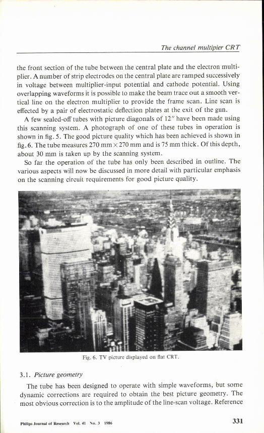
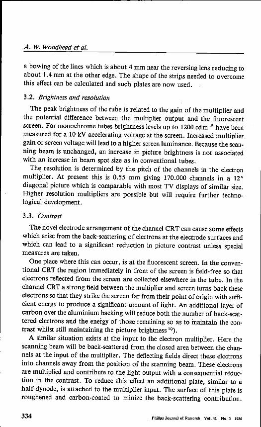
A few sealed-off tubes with picture diagonals of 12" have been made usingthis scanning system. A photograph of one of these tubes in operation isshown in fig. 5. The good picture quality which has been achieved is shown infig. 6. The tube measures 270 mm X270mm and is 75 mm thick. Of this depth,about 30 mm is taken up by the scanning system.
So far the operation of the tube has only been described in outline. Thevarious aspects will now be discussed in more detail with particular emphasison the scanning circuit requirements for good picture quality.
Fig. 6. TV picture displayed on flat CRT.
3.1. Picture geometryThe tube has been designed to operate with simple waveforms, but some
dynamic corrections are required to obtain the best picture geometry. Themost obvious correction is to the amplitude of the line-scan voltage. Reference
Philips Journalof Research Vol. 41 No. 3 1986 331

A. W.Woodhead et al.
to fig. 4 will show that the angle required to scan a line at the top ofthe pictureis less than that at the bottom. The required variation in amplitude can be ap-proximated by an exponential function and this correction is applied at fieldrate to the line-deflection signal. For a typical beam energy of 400 eVthe maxi-mum line-scan amplitude is about 140 V peak-to-peak. .
The second important correction is to the shape of the ramped waveformsapplied to the frame deflection strips. So far the operation of the tube has beendescribed in terms of linear ramped waveforms, as shown in fig. 7. This does
Time_.. t, • time forone fjeld
Fig. 7. Linear ramped waveforms.
not produce a completely linear frame scan so that small periodic variations inthe vertical velocity occur which lead to brightness variations related to thepitch of the frame strips. Additional problems can arise if the timing of theramps is not accurate, as the beam can either travel too quickly or dwell toolong between ramps leading to dark or bright narrow bands corresponding tothe frame strips.
To overcome these difficulties, the field-ramp generation needs to meet tworequirements. The first is that the start. of ramp N + 2 should coincide with theend of ramp N with an accuracy better than ± 2 us. The second requirement isthat the generated ramps depart slightly from linearity in a precisely definedmanner. This is achieved by superimposing onto the ramps a periodic wave-form a few volts in amplitude. In exaggerated form the ramps then appear asshown in fig. 8. The shape of the correction to be applied can be calculated,but it is dependent upon the height of the beam above the deflector plate. Thisin turn is determined by the geometry of the reversing lens. Manufacturingtolerances can lead to small variations in this beam height, so provision hasbeen made to alter the form of the applied correction. This can be done usingthe field ramp generation circuit shown in fig. 9 which also provides very ac-
332 Philip, Journalof Research Vol.41. No. 3 1986

The channel multipier CRT
t,
Fig. 8. Corrected ramped waveforms.
- To fielddeflectors
ts = Ramp start
t, • Ramp finish
te' End of field
Fig. 9. Field scan circuit.
curate ramp timing. The output stage is a high-voltage integrator which gen-erates the basic linear ramp. Accurate timing is achieved by controlling bothramp start and finish times with a ramp clock signal.
To achieve accurate timing it is necessary to use a feedback loop which com-pares the time of the ramp end with a reference time derived from the clockand to use any error to generate a correction to the integrator drive amplitudevia the diode Dl, The corrections to the linear ramp are generated from valuesstored in a random access memory (RAM) by a D-A converter and are addedin at the integrator input. Using this system timing errors of less than ± 1.5 IJSare obtained and any required correction waveform can be generated simplyby loading the RAM with the appropriate data.
A further geometric correction that has been incorporated is a shaping ofthe deflection strips. If the strips are straight, then at the edge of the picturethe velocity of the beam in the vertical direction is less than that at the centreand the deflection of the beam onto the multiplier occurs sooner. This leads to
PhllIps Journalof Research Vol. 41 No. 3 1986 333
A. W. Woodhead et al.
a bowing of the lines which is about 4 mm near the reversing lens reducing toabout 1.4 mm at the other edge. The shape of the strips needed to overcomethis effect can be calculated and such plates are now used.
3.2. Brightness and resolution
The peak brightness of the tube is related to the gain of the multiplier andthe potential difference between the multiplier output and the fluorescentscreen. For monochrome tubes brightness levels up to 1200 cdrrr" have beenmeasured for a 10 kV accelerating voltage at the screen. Increased multipliergain or screen voltage williead to a higher screen luminance. Because the scan-ning beam is unchanged, an increase in picture brightness is not associatedwith an increase in beam spot size as in conventional tubes.
The resolution is determined by the pitch of the channels in the electronmultiplier. At present this is 0.55 mm giving 170.000 channels in a 12"diagonal picture which is comparable with most TV displays of similar size.Higher resolution multipliers are possible but will require further techno-logical development.
334 Phlllps Journalof Research Vol.4l No. 3 1986
3.3. Contrast
The novel electrode arrangement of the channel CRT can cause some effectswhich arise from the back-scattering of electrons at the electrode surfaces andwhich can lead to a significant reduction in picture contrast unless specialmeasures are taken.
One place where this can occur, is at the fluorescent screen. In the conven-tional CRT the region immediately in front of the screen is field-free so thatelectrons reflected from the screen are collected elsewhere in the tube. In thechannel CRT a strong field between the multiplier and screen turns back theseelectrons so that they strike the screen far from their point of origin with suffi-cient energy to produce a significant amount of light. An additional layer ofcarbon over the aluminium backing will reduce both the number of back-scat-tered electrons and the energy of those remaining so as to maintain the con-trast whilst still maintaining the picture brightness 10).
A similar situation exists at the input to the electron multiplier. Here thescanning beam will be back-scattered from the closed area between the chan-nels at the input of the multiplier. The deflecting fields direct these electronsinto channels away from the position of the scanning beam. These electronsare multiplied and contribute to the light output with a consequential réduc-tion in the contrast. To reduce this effect an additional plate, similar to ahalf-dynode, is attached to the multiplier input. The surface of this plate isroughened and carbon-coated to minize the back-scattering contribution.
The channel multipier CRi
With these measures the resulting contrast is comparable with that of a con-ventional colour CRT.
3.4. Power consumptionThe monochrome channel multiplier CRT is a relatively low-power display
because it combines the high efficiency of light generation found in conven-tional CRT's with the ease of deflection resulting from the use of a low-energyscanning electron beam. The overall power consumption of the presentversion of the tube and its scan circuits is about 9 W when displaying a picturewith a mean brightness of 200 cd m -2. Of this power 1.5 W is used for gener-ating the light output, 3.5 W is consumed in the scan circuitry, 2 W by theelectron multiplier supplies and 2 W by the electron gun supplies and heater.Further development of the tube circuits and the use of a low-power heaterwill allow the' overall power consumption of a monochrome tube to bereduced to below 5 W.
The introduetion of colour into the tube produces an increase in power con-sumption of between 4 Wand 12 W, depending upon which of the colour-selection sequences to be described in sec. 4.3 is used. An advantage which thecolour channel multiplier CRT offers over the shadow-mask CRT is that vir-tually all the current directed towards the screen excites the colour phosphors,whereas in a shadow-mask tube about 80070 of that current is absorbed by theshadow-mask. This means that the extra high tension (BHT) power requiredfor the channel multiplier CRT will only be about 25% of that of a shadow-
. mask tube having the same screen size and picture brightness.
4. Colour tubesOne of the important advantages of the CRT as a display device is that it
can produce a wide colour gamut over a large luminance range. A mono-chrome tube, such as the 12" tube which has been described, has many appli-cations. However, a tube with a full colour capability is essential to achievethe widest possible acceptance. A three-beam, shadow-mask colour-selectionsystem such as that employed in most colour cathode-ray tubes, has severe dis-advantages if adapted to the thin channel multiplier CRT. The folded-beamdeflection system presents severe convergence problems in a three-beam ap-proach, whilst a third of the channels must be dedicated to each of the threeprimary colour beams with a consequent loss of resolution. A single-gun ap-proach with colour selection being made on the output side of the multiplierhas therefore been adopted and several methods have been investigated.
One of the simplest ways of producing colours makes use of penetrationphosphor 11) in which a change in screen voltage leads to a change in the colour
Philip, Journul of Research Vol. 41 No. 3 1986 335
A. W Woodhead et al.
of the light emitted. Penetration phosphors in common use have only twoprimary colours so that only a limited colour gamut is available, but for anumber of applications this is adequate. A channel multiplier CRT with a redIgreen penetration phosphor has been made which had a colour range from redat a screen voltage of 7 kV to yellow-green at 13 kV. One advantage offered bythe channel multiplier CRT is that, unlike a conventional penetron tube, thedeflection sensitivity does not alter with screen potential. Thus, the tube doesnot require the additional circuit complexity to correct for changes in deflec-tion sensitivity with colour and has no convergence problems.Two methods of achieving full colour have been investigated 12). Both of
these entail placing an additional electrode structure on the multiplier outputto direct the electrons emerging from the multiplier onto the desired colourphosphor on the screen.
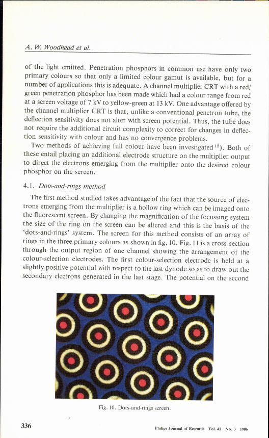
4.1. Dots-and-rings method
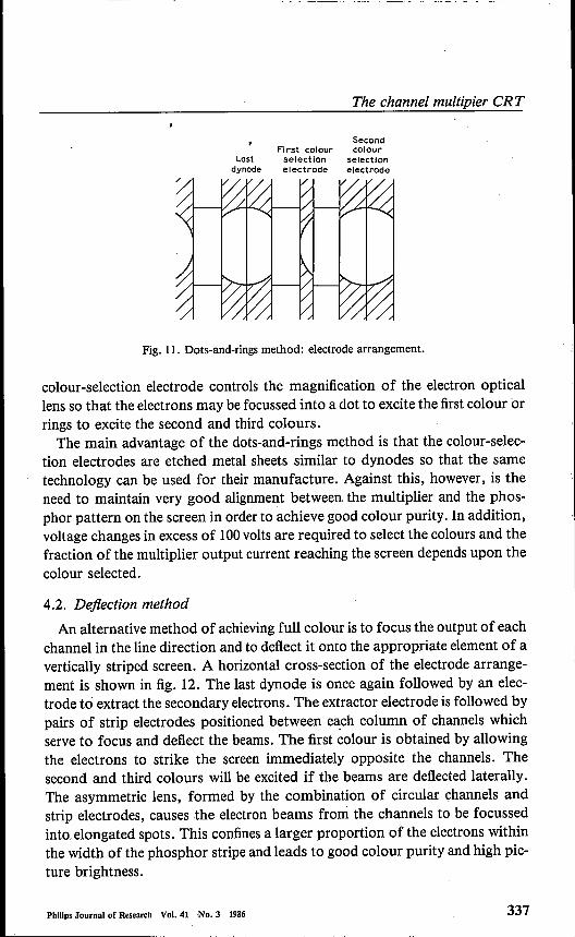
The first method studied takes advantage of the fact that the source of elec-trons emerging from the multiplier is a hollow ring which can be imaged ontothe fluorescent screen. By changing the magnification of the focussing systemthe size of the ring on the screen can be altered and this is the basis of the'dots-and-rings' system. The screen for this method consists of an array ofrings in the three primary colours as shown in fig. 10. Fig. 11 is a cross-sectionthrough the output region of one channel showing the arrangement of thecolour-selection electrodes. The first colour-selection electrode is held at aslightly positive potential with respect to the last dynode so as to draw out thesecondary electrons generated in the last stage. The potential on the second
336 Philips Journalof Research Vol. 41 No. 3 1986
Fig. ID. Dots-and-rings screen.
The channel multipier CR T
SecondFIrst colour colour
Lost selection seteettondynode electrode electrode
Fig. 11. Dots-and-rings method: electrode arrangement.
colour-selection electrode controls the magnification of the electron opticallens so that the electrons may be focussed into a dot to excite the first colour orrings to excite the second and third colours.The main advantage of the dots-and-rings method is that the colour-selec-
tion electrodes are etched metal sheets similar to dynodes so that the sametechnology can be used for their manufacture. Against this, however, is theneed to maintain very good alignment between the multiplier and the phos-phor pattern on the screen in order to achieve good colour purity. In addition,voltage changes in excess of 100volts are required to select the colours and thefraction of the multiplier output current reaching the screen depends upon thecolour selected.
4.2. Deflection methodAn alternative method of achieving full colour is to focus the output of each
channel in the line direction and to deflect it onto the appropriate element of avertically striped screen. A horizontal cross-section of the electrode arrange-ment is shown in fig. 12. The last dynode is once again followed by an elec-trode to extract the secondary electrons. The extractor electrode is followed bypairs of strip electrodes positioned between each column of channels whichserve to focus and deflect the beams. The first colour is obtained by allowingthe electrons to strike the screen immediately opposite the channels. Thesecond and third colours will be excited if the beams are deflected laterally.The asymmetrie lens, formed by the combination of circular channels andstrip electrodes, causes the electron beams from the channels to be focussedinto. elongated spots. This confines a larger proportion of the electrons withinthe width of the phosphor stripe and leads to good colour purity and high pic-ture brightness.
Phillps Journalof Research Vol. 41 No. 3 1986 337

A. W. Woodhead et al.
r:::=::::J--,. Oef leetiene±:J""'--- electrodes
\Focus Face plateelectrode with phosphor
stripes
Fig. 12. Deflection method: electrode arrangement.
The main advantages of the deflection method are the low switching voltagesrequired, of the order of ± 50 V, and the less stringent requirements for multi-plier screen alignment. The main disadvantage is the difficulty of providing thedeflector strips on the output of the multiplier. .This latter problem has been solved for small-scale experiments in the labor-
atory by using 'photo-etched glass, a material for which the rate of etching isincreased by exposure to ultra-violet radiation. In this way the method can beused to make complex components, particularly those which contain parallel-sided slots. The deflection component consists of a plate having a series ofsuch slots which are aligned with the rows of channels as shown in fig. 13. Tiebars are also included to increase the rigidity of the component. Pairs of elec-
Electrodes
Chonnel
Fig. 13. Detail of glass deflector component.
338 Phlllps Journni of Resenrch Vol.41. No. 3 1986

The channel multipier CR T
trodes are provided by coating the bars with metal by evaporation and cuttingalong the tops of the bars with a laser. Both the colour-selection methodswhich have been investigated by experiments carried out in a demountablevacuum system, combined with computer-aided, electron ray tracing calcula-tions, have been shown to be capable of giving good colour purity and uni-forrnity. A photograph of a display obtained in the vacuum demountableequipment is shown in fig. 14. This multiplier had an active area of 50 mm X50 mm and a channel pitch of 0.77 mm. A complete TV picture is shown. Itcontains less than 5000 picture points so that it produces a very coarse image,but illustrates the effectiveness of the approach.
Fig. 14. Colour display on demountable equipment.
4.3. Circuit considerationsSince these two methods of achieving full colour utilize a single gun, the
beam must be shared time-sequentially between the three colours at a ratewhich gives acceptable picture quality with the minimum circuit complexity.Simple field-sequential switching in which successive TV signal fields are dis-played in the primary colours leads to severe (16.67 Hz) large-area flicker andcolour break-up of moving picture content. This may be overcome by raisingthe display field-scan rate to 150 Hz or more but it requires trebling the line-scan as well as the video bandwidth and also two complete ROB. field storescapable of being read out at three times the input rate (involving clock rates ofabout 40 MHz if digital field stores are used).
Another possibility is simple line-sequential switching in which successivelines in each raster field are displayed in red, green and blue. Unfortunately,this reduces the number of picture lines in each colour by a factor of three,leading to considerable loss of resolution and unacceptable line-crawl effects.Alternatively, as with a number of early experimental single-gun colour
Philips Journalof Research Vol. 41 No. 3 1986 339
A. W. Woodhead et al.
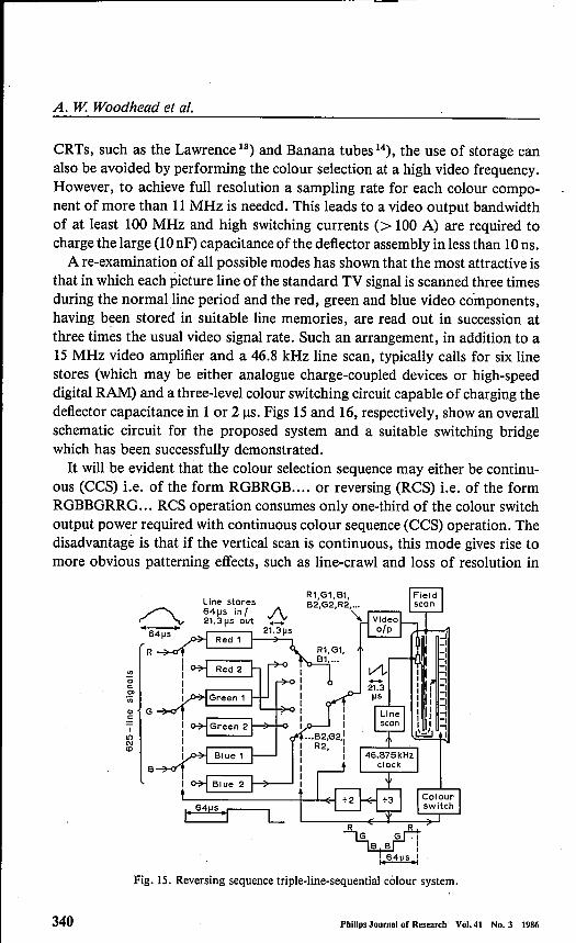
CRTs, such as the Lawrence 13) and Banana tubes 14), the use of storage canalso be avoided by performing the colour selection at a high video frequency.However, to achieve full resolution a sampling rate for each colour compo-nent of more than 11MHz is needed. This leads to a video output bandwidthof at least 100 MHz and high switching currents (> 100 A) are required tocharge the large (10nF) capacitance ofthe deflector assembly in less than 10ns.A re-examination of all possible modes has shown that the most attractive is
that in which each picture line of the standard TV signal is scanned three timesduring the normalline period and the red, green and blue video components,having been stored in suitable line memories, are read out in succession atthree times the usual video signal rate. Such an arrangement, in addition to a15 MHz video amplifier and a 46.8 kHz line scan, typically calls for six linestores (which may be either analogue charge-coupled devices or high-speeddigital RAM) and a three-level colour switching circuit capable of charging thedeflector capacitance in 1 or 21JS. Figs 15 and 16, respectively, show an overallschematic circuit for the proposed system and a suitable switching bridgewhich has been successfully demonstrated.It will be evident that the colour selection sequence may either be continu-
ous (CCS) i.e. of the form RGBRGB .... or reversing (RCS) i.e. of the formRGBBGRRG ... ReS operation consumes only one-third of the colour switchoutput power required with continuous colour sequence (CCS) operation. Thedisadvantage is that if the vertical scan is continuous, this mode gives rise tomore obvious patterning effects, such as line-crawl and loss of resolution in
!!oc:0>"in
II()
'"co
Fig. IS. Reversing sequence triple-line-sequential colour system.
340 Phlllps Journal of Research Vol.41 No.3 1986

The channel multipier CRT
~I I,
-L------ir Pu IseIIIp generation-ye sync
r: --- - - -,1 ) IOptocouPlersI1 J 64~sL _ -1-. - - 1<-'-1
.r+i Lr-J.r--h.
1 1"l..!..IUJ"1...
Buffers ...r-Tt.m.r.,_:.rhsh.lr-
A
:ti
B
Bce
-ye
Fig. 16. Three-level reversing colour-sequence switch.
the vertical direction. However, by stepping the vertical scan only after everythird line, this limitation can be removed, since the R, G and B components ofeach line are then overlaid and the eye cannot detect the residual temporalerrors. Consequently the viewer will see an accurately registered picture freefrom additional artefacts.Pending the availability of a full-sized display and line-store standards con-
verter, initial experiments have been carried out as mentioned in sec. 4.2 using50 mm X 50 mm samples of channel multipliers and screens with 0.77 mm and0.55 mm channel pitch in a demountable vacuum chamber. These werescanned in a conventional manner at normal TV rates and a complete colourpicture was demonstrated (fig. 14). This reduced resolution picture was ob-tained by using the simple line-sequential mode and deleting two colour switchsteps in each field-scan to give the best compromise between the inevitableline-crawl and flicker effects and loss of vertical resolution. In this case, switch-ing power was too low to be significant so that the more advantageous CCSmode could be used.
Phlllps Journalof Research Vol. 41 No. 3 1986 341
A. W. Woodhead et al.
5. Concluding remarks
The results achieved so far have demonstrated that a cathode-ray tube canbe made which is both thin and flat and consumes less power than a conven-tional tube. As a monochrome display it can begin to compare in performancewith the traditional cathode-ray tube. In its colour version the raster-scanningsystem remains unchanged so that the shape and volume of the tube are un-altered. The feasibility of a system for displaying colour pictures has been de-monstrated. It remains to apply this approach in a large-area sealed-off tube.The indications are that, whilst the power consumption will be larger than thatof the monochrome version, it will still be conservative.The development of the tube and its associated circuits as a system has
hardly begun. The interaction between electron-optic design, manufacturingtolerances and control circuitry is very complex. The best performance thatcan be achieved most economically will ultimately depend upon how success-fully the demands made in these different areas are balanced.Part of the work described here was supported by the Procurement Execu-
tive, U.K. Ministry of Defence DCVD.
REFERENCES1) D. Washington, V. Duchenois, R. Polaert and R. M. Beasley, Acta Electronica 14,
201 (1971).2) J. Adams and B. W. Manley, Philips Tech. Rev. 28, 151 (1967).3) D. Washington, A. J. Guest and A. G. Knapp, Adv. in Electronics and Electron Physics
64A, 101 (1985).4) A. W. Woodhead, D. Washington, C. D. Overall, J. R. ManselI, A. G. Knapp and
D. L. Lamport, Proc. of the Society for Information Display 23, 113 (1982).5) A. G. Knapp, D. Washington, A. J. Guest, R. W. A. Gill, R. Pook and L. H. Francis,
lEE Proc. 1311, 6 (1984). •6) C. Sineair, SID Digest XII, 138 (1981).7) A. Ohkoshi, S. Hiroki, T. Nakano, T. Natori and M. Hatanaka, IEEE Trans. Con-
sumer Electronics CE 28, 431 (1982).- 6) Y. Funatsukuri, J. of Electronic Engineering 22, 74 (1985). ".
9) D. L. Lamport, A. W.Woodhead, D. Washington and C. D. Overall, IEEProc.13l1,10 (1984).
10) J. R. ManselI and A. W. W oodhead, J. Phys. D 16, 2269 (1983).") S. Sherr, Electronic Displays, ed. John WHey, New York, 126 (1979).12) J. R. ManselI, A. W. Woodhead, A. G. Knapp and H. D. Stone, lEE Proc. 1311, 13
(1984). .13) R. Dressier, Proc. IRE 41,851 (1953).14) P. Schagen, Proc. lEE 108,577 (1961).
342 Phillps Journalof Research Vol.41 No.3 1986