the characteristic is that the steps for analyzing a clocked synchronous state-machine are almost...
Post on 22-Dec-2015
215 views
TRANSCRIPT

The characteristic is that the steps for analyzing a clocked synchronous state-machine are almost the same. So, it will become very simple if we have learned the basic principles. NextReturn
7.4 Clocked Synchronous State-Machine Analysis
The goal of a sequential circuit analysis is to determine the next-state and output functions so that the behavior of a circuit can be predicted.
Introduction
In this section, we will discuss how to analyze a clocked synchronous state-machine. It’s one of the main emphases in this course.
Turn-the-
crank

NextBackReturn
7.4 Clocked Synchronous State-Machine Analysis
Specialized Words
transition table 转换表state table 状态表
state/output table 状态 / 输出表state diagram 状态图
flip-flop 触发器excitation equation 激励(驱动)方程
transition/state equation 转移 / 状态方程output equation 输出方程characteristic equation 特性(征)方程

2. What are the excitation equation, transition equation, and output equation ?
NextBackReturn
7.4 Clocked Synchronous State-Machine Analysis
Review
1. What are the two types the state-machine structure include? What characteristic does it have for each one?
Mealy machineMoore machine
Z = G (Q n, X )Z = G (Q n)
Output equation
Excitation equationTransition equation Next-state logic
F
State memory input W
Output logic G
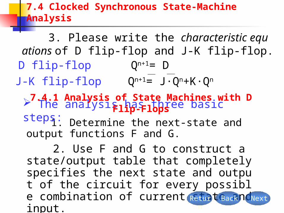
2. Use F and G to construct a state/output table that completely specifies the next state and output of the circuit for every possible combination of current state and input.
1. Determine the next-state and output functions F and G.
NextBackReturn
7.4 Clocked Synchronous State-Machine Analysis
The analysis has three basic steps:
3. Please write the characteristic equations of D flip-flop and J-K flip-flop.
D flip-flop Qn+1= DJ-K flip-flop Qn+1= J·Qn+K·Qn
7.4.1 Analysis of State Machines with D Flip-Flops
Q0
Q1
D0
D1
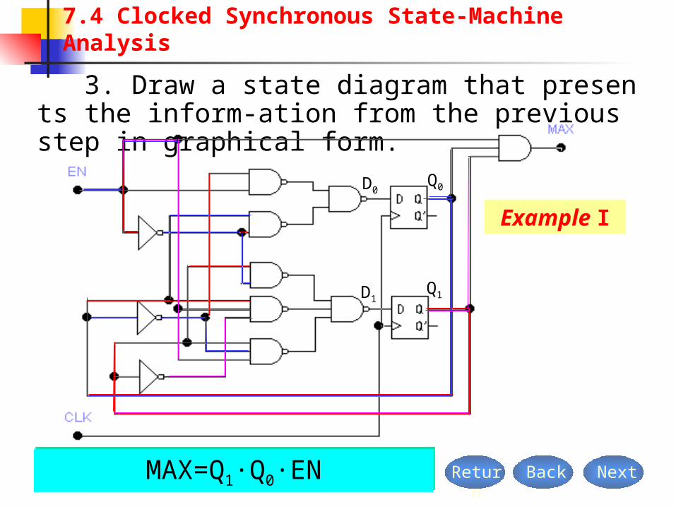
Example I
3. Draw a state diagram that presents the inform-ation from the previous step in graphical form.
NextBackReturn
7.4 Clocked Synchronous State-Machine Analysis
ENQEN QD 000 ENQQENQ QENQD 010111 MAX=Q1·Q0·EN

NextBackReturn
7.4 Clocked Synchronous State-Machine Analysis
Output equation
MAX=Q1·Q0·EN
Transition equations
ENQQENQ QENQDQ
EN QENQDQ
0101111n
1
0001n
0
Excitation equations
EN QENQD 000
ENQQENQ QENQD 010111
How can we obtain the transition equations from the excitation equations?

NextBackReturn
7.4 Clocked Synchronous State-Machine Analysis
1
0 00 11 01 1
Q1 Q0
0Transition/output tableEN
MAX Q Q 1n0
1n1
MAX Q Q 1n0
1n1
1
S0
S1
S2
S3
S
0State/output tableEN
MAX S 1n
000 0
S0
S1
S2
S3
MAX S 1n
S1 S2
S3
S0
000 1
MAX=Q1·Q0·EN
EN QENQQ 001
0 n
ENQQENQ QENQQ 010111n
1
0110
001 1
000 0
000 1
010 1
1010

NextBackReturn
7.4 Clocked Synchronous State-Machine Analysis
S0 S1
S2S3
1/0 0/0
State diagram
0/0
0/00/0
1/0
1/0
1/1
SEN/MAX
1
S0
S1
S2
S3
S
0State/output tableEN
MAX S 1n
000 0
S0
S1
S2
S3
MAX S 1n
S1 S2
S3
S0
000 1
What is the function of the logic circuit ?It’s a modulo-4 2-bit binary counter with enable.Simulation

Q0
Q1
Q2
D0
D1
D2
Next
Back
Return
7.4 Clocked Synchronous State-Machine Analysis
20010 Q XQXQD 121021 QQ XQXQQD Y XQQQD 0022 0120121 QQQQQQZ 02122 QQQQZ Example II

02122 QQQQZ NextBackReturn
7.4 Clocked Synchronous State-Machine Analysis
Output equation
Transition equations
Excitation equations
121021 QQ XQXQQD 20010 Q XQXQD
Y XQQQD 0022
1210211
1 QQ XQXQQDQ n20010
10 Q XQXQDQ n
Y XQQQDQ 00221
2 n
0121 QQQZ

NextBackReturn
7.4 Clocked Synchronous State-Machine Analysis
Transition/output table
20011
0 Q XQXQQ n
0 1
0 0 00 0 10 1 0 0 1 11 0 10 0 11 1 10 1 1
0 0 00 0 10 1 00 1 11 0 01 0 11 1 01 1 1
Q2Q1Q0
0 0XY
1n0
1n1
1n2 Q Q Q 1n
01n
11n
2 Q Q Q
1 0 00 0 11 1 0 0 1 11 0 10 0 11 1 10 1 1
1 1
0 0 10 1 10 0 0 0 1 01 0 10 0 11 1 10 1 1
1 01n
01n
11n
2 Q Q Q 1n0
1n1
1n2 Q Q Q
0 0 10 1 10 0 0 0 1 01 0 10 0 11 1 10 1 1
Z1Z2
1 01 01 00 01 11 01 11 1

NextBackReturn
7.4 Clocked Synchronous State-Machine Analysis
State diagram
S0 S1
S3S2
1x/100x/10
SXY/Z1Z2
S5
S6 S7
S4
1x/10
1x/00
1x/1001/10 xx/11
0x/0000/10
00/10
01/10xx/11
xx/11
xx/10
Simulation
State/output table
1nS
s0
s1
s2
s3
s4
s5
s6
s7
S
00XYZ1Z2
1 01 01 00 01 11 01 11 1
01 11 101nS 1nS 1nS
s0
s1
s2
s3
s5
s1
s7
s3
s4
s1
s6
s3
s5
s1
s7
s3
s1
s3
s0
s2
s5
s1
s7
s3
s1
s3
s0
s2
s5
s1
s7
s3

NextBackReturn
7.4 Clocked Synchronous State-Machine Analysis
7.3.3 Analysis of State Machines with J-K Flip-Flops
Q0
Q1
Q2
J0 J1J2
K0 K1K2
Excitation equations
20 QJ 1K0
01 QJ 01 QK
012 QQJ 1K2
Transition equations
021
0 QQQ n
01011
1 QQQQQ n
0121
2 QQQQ n

NextBackReturn
7.4 Clocked Synchronous State-Machine Analysis
Transition/output table
0 0 10 1 00 1 1 1 0 00 0 00 1 00 1 00 0 0
0 0 00 0 10 1 00 1 11 0 01 0 11 1 01 1 1
Q2 Q1 Q0 QQQ 1n0
1n1
1n2
0000 1111
C
State diagram
Q2Q1Q0
/C
000 001 010
011100
111 110 101/1
/0 /0
/0/0
/1
/1 /1
Simulation

Exercises
P647~649 7.9, 7.15, 7.16, 7.17, 7.18, 7.19 BackReturn
7.4 Clocked Synchronous State-Machine Analysis
Summary
1. Determine the excitation equations.
4. To construct a transition/output table. 5. To construct a state/ output table.
2. Determine the transition equations. 3. Determine the output equations.
6. (Optional) Draw a state diagram.
The detailed steps for analyzing a clocked synchronous state machine are as follows: