the cost effectiveness of flame sprayed coatings … · the cost effectiveness of flame sprayed...
TRANSCRIPT
THE COST EFFECTIVENESS OF FLAME SPRAYED COATINGS
FOR SHIPBOARD CORROSION CONTROL
June 1990
Puget Sound Naval ShipyardThermal Spray DivisionLori Crawford, Shop 26
Bremerton, WA 98314-5000
Report Documentation Page Form ApprovedOMB No. 0704-0188
Public reporting burden for the collection of information is estimated to average 1 hour per response, including the time for reviewing instructions, searching existing data sources, gathering andmaintaining the data needed, and completing and reviewing the collection of information. Send comments regarding this burden estimate or any other aspect of this collection of information,including suggestions for reducing this burden, to Washington Headquarters Services, Directorate for Information Operations and Reports, 1215 Jefferson Davis Highway, Suite 1204, ArlingtonVA 22202-4302. Respondents should be aware that notwithstanding any other provision of law, no person shall be subject to a penalty for failing to comply with a collection of information if itdoes not display a currently valid OMB control number.
1. REPORT DATE JUN 1990
2. REPORT TYPE N/A
3. DATES COVERED -
4. TITLE AND SUBTITLE The Cost Effectiveness of Flame Sprayed Coatings for ShipboardCorrosion Control
5a. CONTRACT NUMBER
5b. GRANT NUMBER
5c. PROGRAM ELEMENT NUMBER
6. AUTHOR(S) 5d. PROJECT NUMBER
5e. TASK NUMBER
5f. WORK UNIT NUMBER
7. PERFORMING ORGANIZATION NAME(S) AND ADDRESS(ES) Naval Surface Warfare Center CD Code 2230 - Design Integration ToolsBldg 192 Room 128 9500 MacArthur Blvd Bethesda, MD 20817-5700
8. PERFORMING ORGANIZATIONREPORT NUMBER
9. SPONSORING/MONITORING AGENCY NAME(S) AND ADDRESS(ES) 10. SPONSOR/MONITOR’S ACRONYM(S)
11. SPONSOR/MONITOR’S REPORT NUMBER(S)
12. DISTRIBUTION/AVAILABILITY STATEMENT Approved for public release, distribution unlimited
13. SUPPLEMENTARY NOTES
14. ABSTRACT
15. SUBJECT TERMS
16. SECURITY CLASSIFICATION OF: 17. LIMITATION OF ABSTRACT
SAR
18. NUMBEROF PAGES
313
19a. NAME OFRESPONSIBLE PERSON
a. REPORT unclassified
b. ABSTRACT unclassified
c. THIS PAGE unclassified
Standard Form 298 (Rev. 8-98) Prescribed by ANSI Std Z39-18
These reports were prepared as an account of government-sponsored work.
Neither the United States, nor the Maritime Administration, nor any personacting on behalf of the Maritime Administration, (A) makes any warranty orrepresentation, expressed or implied, with respect to the accuracy,
completeness or usefulness of the information contained in this report/manual, or that the use of any information. apparatus. method, or processdisclosed in this report may not infringe privately owned rights; or (B)assumes any liabilities with respect to the use of or for damages resulting
from the use of any information, apparatus, method, or process disclosedin the report. As used in the above, “Persons acting on behalf of theMaritime Administration” includes any employee, contractor, or subcontractor
to the contractor of the Maritime Administration to the extent that suchemployee, contractor, or subcontractor to the contractor prepares, handles,
or distributes, or provides access to any information pursuant to hisemployment or contract or subcontract to the contractor with the MaritimeAdministration. ANY POSSIBLE IMPLIED WARRANTIES OF MERCHANTABILllYAND/OR FITNESS FOR PURPOSE ARE SPECIFICALLY DISCLAIMED.
Abstract
T A B L E O F C O N T E N T S
ObjectivesBackgroundProject OverviewApplication and Life Cycle CostsConclusions and RecommendationsAcknowledgementsList
WIRE
of Photographs
SPRAYED ALUMINUM
ProcessesSubstrate PreparationSealer Application
Figure 1 - Type I System DiagramFigure 2 - Type II System Diagram
Coating CharacteristicsParameters and LimitationsQuality Assurance
Figure 3 - Corrosion Control ThermalSpray Job Control Record
Operator Qualification and TrainingApplication CostsMaintenance, Repair Methods and Cost
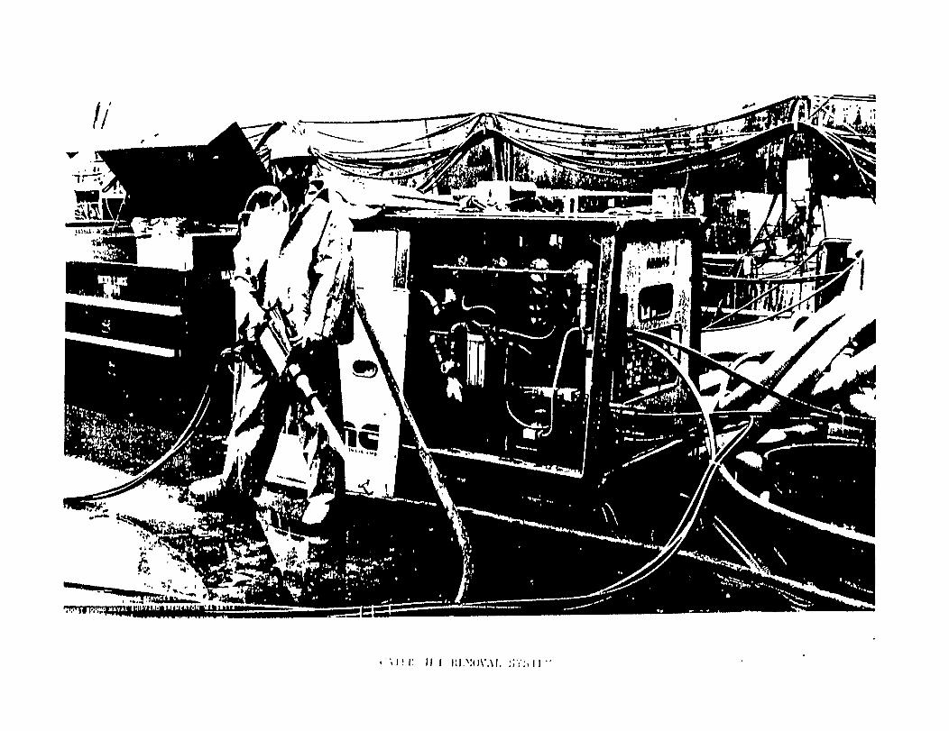
Water Jet Removal System PhotographGeneral Information
Aluminum Coating ApplicationWorking Area RequirementsSafety Equipment
PAINT
ProcessesSubstrate PreparationPreferred Applications
Inorganic ZincEpoxy Polyamide
parameters and LimitationsApplication of Paint CoatingsQuality AssuranceOperator Qualification and TrainingApplication CostsMaintenance and Repair MethodsGeneral Information
General AdvantagesSurface Preparation LimitationsCuring or Drying and Recoat TimesVolatile Organic Compounds (VOC)
iii
iiivivv
vi
1
235
679
111314
17181920
21
22232526282931333536373940414243

TABLE OF CONTENTS
WIRE SPRAYED ALUMINUM AND PAINTEQUIPMENT AND MATERIAL COSTS AND CONSUMABLES
Equipment and Material CostsContainerized Flame Spray Unit Photographs
Corrosion Control Shop Consumables
WIRELIFE
WIRE
SPRAYED ALUMINUM AND PAINTEXPECTANCY AND LIFE CYCLE COST COMPARISONS
Life ExpectancyThermal Spray and Paint ComparisonLife Cycle Cost Analysis
20 Year Cost Comparison GraphCorrosion Tests
Test Panel Parameter SheetsMetallurgy Lab Corrosion Test EvaluatCorrosion Test Panel Photographs
SPRAYED ALUMINUMRECOMMENDED AREAS AND HISTORICAL PHOTOGRAPHS
New ConstructionRepair Areas for Thermal SprayHistorical Photographs
REFERENCES
44
45
68
70
717273
75
ion Report
76
777880
81

ABSTRACT
With corrosion control taking up almost 30 percent of the cost ofmaintaining ships, the maritime industry must respond byutilizing the most effective and economical methods of corrosioncontrol available. Wire sprayed aluminum (WSA) has proven to bean effective corrosion control method for many shipboardapplications. Data will be compiled which will assist shipowners in comparing the cost of WSA coatings with selectedrepresentative paint systems regarding application, repair, andlife cycle costs. We will also describe methods used to repairWSA and compare the life cycle cost of hese coatings toconventional paint coating systems. We will also help the userdetermine ship areas best suited for WSA.
OBJECTIVES
The objective of this project is to develop guidelines forselecting shipboard areas where wire sprayed aluminum coatingswould be the most effective method of corrosion control. Withinthe scope of the project we will determine application costs ofWSA and selected representative paint systems. Applicationparameters and constraints as well as repair methods will becompared. We will also analyze life cycle costs of currentlyavailable corrosion control methods and recommend the most costeffective shipboard applications for WSA.
BACKGROUND
Corrosion control takes up almost 30 percent of the cost ofmaintaining ships. The maritime industry must respondutilizin g the most effective and economical methods ofcontrol to extend the life cycle of components.
Wire sprayed aluminum is a proven, effective corrosionmethod for many shipboard applications.
bYcorrosion
control
i

PROJECT OVERVIEW
Various data was compiled to assist the maritime industry incomparing the cost of wire sprayed aluminum coatings withrepresentative paint coatings.
Application, repair, and life cycle costs were identified.Repair methods for wire sprayed aluminum and paint coatingsystems were described as well as quality assurance andparameters and limitations.
Wire sprayed aluminum and paint facility setup costs wereinvestigated. Current cost information and equipmentdescriptions are provided.
Corrosion tests were performed in an accelerated salt spray boothfor a total of 2,360 hours. For the first 2,000 hour test, thescribing of the faulted samples did not completely penetrate tothe base metal. The Panels were scribed a second time to exposethe base metal and returned to the salt sprayhour test.
Six corrosion resistant systems were tested.of eight panels for each system, four faultedfaulted.
booth for the 360
There was a totaland four non-
System 1: Wire sprayed aluminum and Navy specification sealcoating system (per #2138). The surface preparation was SP-5,white metal blast. Test panels 1 through 8.
System 2: Wire sprayed aluminum and commercial seal coat system(International brand paint). The surface preparation was SP-5,white metal blast. Test panels 9 through 16.
System 3: Navy specification: Mare Island series (epoxypolyamide) seal coating system (per =631). The surface
Test panels 17preparation was SP-10, near-white metal blast.through 24.
System 4: Commercial equivalent to Navy specification MareIsland system (International brand paint coating system, “FP”series). The surface preparation was Sp-10, near-white metalblast. Test panels 25 through 32.
System 5: Navy specification “inorganic zinc”, Mare Island The surface preparation was SP-10, near-white metalsystem.
blast. Test panels 33 through 40.
System 6: Commercial seal coat system: inorganic zinc with "FP"series topcoats (International brand paints). The surfacepreparation was SP-10, near-white metal blast. Test panels 41through 48.
ii

The test panel surface preparation for the selected Navy paintsystems was performed in accordance with Naval Ships TechnicalManual, Chapter 631. Surface preparation for wire sprayedaluminum test panels was in accordance with Military Standard2138. All commercial paint systems surface preparation wasperformed in accordance with manufacturers instructions andspecifications.
The results and conclusions of this test are as follows.
The wire sprayed aluminum/commercial seal coat system used inSystem 2 provided better protection from the salt fog environment than any of the other five systems.
The results from the 360 hour test should be representative ofthe indications found in the six systems. If the test panels hadbeen scribed to the base metal for the first 2,000 hours, thecorrosion and blistering would have been more severe. A moredetailed account is provided in the report.
iii
APPLICATION AND LIFE CYCLE COSTS. — —
Application costs are identified within the report. As expected,thermal spray application costs are more than twice that of mostpaint systems, but certain components, because of their nature,are more cost effective to thermal spray. When looking at lifecycles, a list of components are identified in the report. TheNavy has, historically over the past ten years, consistentlythermal sprayed these components during overhaul periods.
CONCLUSIONS AND RECOMMENDATIONS
Because of sheer numbers, component configuration, andaccessibility, we found it impossible to identify costcomparisons for individual components. Though application costsare identified for thermal spray and paint systems, the threeaforementioned factors must be known and considered before anaccurate cost estimate can be established. Before bidding anythermal spray job, Puget Sound Naval Shipyard either looks at thecomponent or a drawing of the component. Although the reportdoes not give cost comparisons for individual components, theinformation provided will assist the industry in identifyingcomponents aboard naval vessels they may be required to thermalspray during overhauls.
Our recommendation is that this report be used as a guide forapplication selection, repair, quality assurance, parameterdesignation, and facility setup pertinent to equipment. Wefurther recommend that thermal spray be used as a facilitymaintenance tool to combat corrosion. Puget Sound Naval Shipyardcurrently thermal sprays hundreds of components in dry docks andpier side, extending the life cycle of components in severeenvironments.
iv

ACKNOWLEDGEMENTS
Special thanks are given to the following contributors forsupplying materials and technical direction which made thisproject possible:
Bay Shipbuilding Company, Jack SchmidtDavid Taylor Research Center, Karen PooleFlame Spray Leasing, Inc., Sam ClaybrookGeneral Dynamics, Electric Boat Division, Groton,
Connecticut, Raymond ColechiaIngalls Shipbuilding, Kay FreemanInorganic Coatings, Inc., Michael SfirriIntegrated Systems Analysis, Bob Sulit and J. WinkerInternational Paint, Inc., John ShamonNational Steel and Shipbuilding Company, Les Hansen and
Roger SnyderNewport News Shipbuilding, Ted Stewart and J. D. HarwoodNorfolk Shipbuilding and Drydock Company, Larry AmbrosPeterson Builders, Inc., Jim AndersonPuget Sound Naval Shipyard, Design Division, Code 250,
Michael Chan and Dennis WilliamsPuget Sound Naval Shipyard, Occupational Safety and Health
Division, Code 106, Dan Martin
v

LIST OF PHOTOGRAPHS
Water Jet Removal SystemContainerized Flame Spray Unit
Portable Skid/Water Wash BoothRail Extending Through Blast ContainerDrop Table/Round TableThrough Shot From Container Side To BlasterRail Between Blast Container And Spray ContainerSpray Container/Bottle Rack/Bag House/Blast Container/Air Dryer
WSA PanelsPaint PanelsSystems #1 - #6 (Sealed)System #1, Side ASystem #l, Side BSystem #2, Side ASystem #2, Side BSystem #3, Side ASystem #3, Side BSystem #4, Side ASystem #4, Side BSystem #5, Side ASystem #5, Side BSystem #6, Side ASystem #6, Side BLog Bronc Bilge After Arc Spray AluminumCV-63 Head Floor (Thermal Spray Complete)Thermal Sprayed Deck LightGauge Brackets (Thermal Sprayed)Piping Assembly (After Thermal Spray)Thermal Spraying Of Vent Duct InteriorValves (Thermal Spray Complete)Corroded ValveThermal Sprayed FoundationCondenser Being Thermal SprayedCondenser (Thermal Spray Complete)Tie Down (Thermal Sprayed Aluminum)Thermal Sprayed DeckThermal Spraying Inside Of PipeThermal Sprayed Valve
vi

WIRE SPRAYED ALUMINUM
1

PROCESSES
Wire Flame Spray - A metal spraying process where an oxy fuelflame is the source of heat which melts the metal to resprayedin wire form and propels the molten metal onto the substrate.The flame spray process is the oldest metallizing process.
The flame spray process is portable and primarily used for smallcomponents such as valve bodies.
The coating thickness is easily controlled because of the lowdeposition rate and is an advantageous process for sprayingintricate parts.
The wire flame spray process has a lower bond strength thanelectric arc spray (average bond - 2,000 PSI) .
Electric Arc Spray - An electric arc is the source of heatbetween two consumable wires. Compressed air or inert gas isused to propel molten metal onto the substrate.
This system is very portable and utilizes a variety of wirefiller materials.
The electric arc spray system is the least expensive thermalspray process to operate and maintain, has a high bond strength(average 2,500+ PSI), and has the highest production rate.
Disadvantages of the arc process include generation of more dustand fumes than other processes and the high deposition rate makescontrol of coating thickness difficult on intricate parts.
2
SUBSTRATE PREPARATION
Surface Cleaninq - Areas to be thermal sprayed and adjacent areasshall be free from oil, grease, paint, corrosion products,moisture, or any other foreign material that may contaminate thesurface and coating.
Solvent Cleaninq - Prior to masking, blasting, or spraying, allsurfaces which have come in contact with oil or grease shall besolvent cleaned. Vapor degreasing is the preferred method butsolvent washing may be used. Solvents shall not cause anydetrimental attack of the substrate material and must not leaveany residue film on the substrate. Acceptable cleaners areTrichloroethane (Type I or II) in accordance with 0-T-620 orxylene in accordance with ASTM D 846. Cleaning may be done bywiping, brushing, or spraying. Precautions must be taken toprotect any parts which may be attached by the solvents.
Abrasive Cleaninq - Preliminary abrasive blast cleaning may beused to remove heavy or insoluble deposits. An inexpensive,disposable abrasive is recommended. Dust and debris shall beremoved by dry compressed air before solvent cleaning or washing.
Heat Cleaninq - Porous materials that have been contaminated withgrease or oil shall be solvent cleaned. If required, parts shallbe heated invented electric or gas ovens for sufficient time toremove grease or contamination remaining after decreasingcleaning processes. Steel alloys shall be heated to 600 degreesF maximum. Aluminum alloys, except large hardened alloys, shallbe heated to 300 degrees F maximum. Caution shall be given toparts which may distort from original dimensional tolerances(ie., valve seats).
Contaminated Surfaces - Surfaces shall be cleaned with atrisodium phosphate solution, rinsed with clear, potable water,and dried after solvent cleaning.
Maskinq - Masking shall be performed on all adjacent areas whichmay be affected by abrasive blasting or thermal spraying. Themask (tape) must be applied tight enough to prevent grit fromseeping under the mask. When using tape, apply two layers withthe second layer at right angles to the first. The masking shallbe inspected for damage between abrasive blasting and thermalspray processes and shall be replaced if damaged.
Abrasive Anchor Tooth Blastinq - Prior to thermal spraying for t the surface to be prepared by
abrasive blasting to provide an anchor tooth for the thermalspray.
The final surface preparation of the substrate shall be achievedby using aluminum oxide or angular chilled iron grit. Chillediron grit shall not be reused. Only aluminum oxide maybe reused

for anchor tooth blasting. Prior to reuse, the aluminum oxideshall be screened using a 30 mesh screen, visually inspected fordebris and oil contamination, and shall pass an oil contaminationtest.
The blasted surface shall have a white metal blast appearancedefined as a gray-white, uniform metallic color, with and anchortooth (not peened) surface profile of .002" to .003", measuredwith profile tape and a dial micrometer. The surface shall thenbe visually inspected and shall be free of oil, grease, dirt,mill scale, rust, corrosion products, oxides, paint, or otherforeign matter. The color of the clean surface may be affectedby the particular abrasive medium used. Abrasive blastedsurfaces shall not be allowed to come in contact withcontaminated surfaces prior to completion of thermal spray andsealing processes. Prepared surfaces shall be handled only withclean gloves, rags, or slings. Contact with any oil may causefailure of the coating. Blasting shall not be so severe as todistort the component being prepared for thermal spray.
Blast-Spray Restrictions - The thermal spraying operation shallnot proceed if there is visible moisture present on the surfaceof the substrate. Visible evidence of rust bloom or oxidation onthe surface shall be removed by a brush off blast. No thermalspraying shall be conducted if the substrate temperature is notgreater than 10 degrees F above the dew point. The substratesurface shall have a white metal blast appearance. The thermalspray operation shall be started within four hours after anchortooth surface preparation for steel and shall be finished withinsix hours. The thermal spray operation on aluminum shall bestarted within two hours after anchor tooth surface preparationand shall be finished within four hours. If more than 15 minutesis expected to elapse, or if the part must be moved to anotherlocation, the prepared surface shall be protected from moisture,contamination, and fingerprints. Adequate protection willnormally be provided by wrapping with clean paper (free ofnewsprint). For periods longer than four hours, a thermalsprayed flash coat (at least 0.001”) shall be used to protect thesurface until the final thermal sprayed coating can be applied.If the surface becomes deteriorated or contaminated, it shall bereblasted. The flash coated surface shall not be allowed tostand for more than four hours without application of the finalcoating thickness. The substrate or flash coat shall bereblasted if they become contaminated.
4

SEALER APPLICATION (TYPE I AND II)
Application - The seal coat used depends on the normal operatingtemperature of the component to be thermal sprayed. Applicationof seal coats shall be-completed within 24 hours of thermalspraying. Seal coats shall only to applied to clean, dry thermalsprayed surfaces. The presence of moisture in the thermalsprayed coating pores may lead to premature coating failure. Ifthe presence of moisture is suspected, the thermal sprayedcoating shall be heated to 250 degrees F to remove the moisturebefore applying the seal coats.
Requirements - Thermal sprayed aluminum coatings are sealed toprevent moisture, oil, dirt, etc. from attacking the coating ofthe bond. The seal coat must be applied before the coating isexposed to traffic or dampness. The coating shall be sealed assoon as possible after spraying and in all cases within 16 hoursof spraying.
Type I Sealer Application - A Type I sealer is a high temperaturecoating system for use on structures and components whoseoperating surface temperature is 175 degrees F and above. Thesecomponents are generally found in machinery spaces and includesteam valves, piping, and traps. For high temperatureapplications, the thermal spray coating is applied to a whitemetal blasted surface with a 2 - 3 mil anchor tooth profile and athermal spray coating thickness of 10 - 15 roils. (See Figure 1)
The thermal spray coating is sealed and coated with two coats ofheat resistant aluminum paint, 1.5 mil DFT per coat. The firstsealing coat shall be applied as soon as practical but no laterthan four hours after spraying.
Type Sealer Application - A Type II sealer is a lowtemperature coating system used for the corrosion protection ofsteel components whose operating temperature is below 175 degreesF. For example, stanchions and foundations.
A pure aluminum coating is deposited on the surface to beprotected. The aluminum coating is then covered with a thin coatof diluted Formula 150, Formula 150, and Formula 151 inaccordance with MIL-P-24441. (See Figure 2)
Topcoacs - Topcoats for thermal sprayed components, if required,shall be as specified in the applicable contract, work orderf
specification ~ship requirement, or NAVSEA publication.
5

Figure 1 - Type I System for High-Temperature Applications

Figure 2 - Type II System for Low-Temperature Applications

COATING CHARACTERISTICS
The wire sprayed aluminum (WSA) process provides for theprotection of iron and steel in corrosive environments wherepaint coatings are not effective. The WSA process providesbarrier protection as well as galvanic coating protection.
The steel surface being sprayed with the WSA process remains cooland there is no distortion. There is also no effect on themetallurgical properties of the steel. The WSA coating must besealed and topcoated with the appropriate paint system to fillthe pores of the coating providing protection from moisture andimproving the appearance and life of the coating. This alsosimplifies maintenance and requires only the renewal of thesealer. Topcoats provide additional barrier protection and acosmetic finish.
The general advantages of thermal sprayed coatings that should beinitially considered when choosing a protective coating systemare as follows:
1. Predictable life.2. Single application system.3. No drying time is needed.4. Protection of damaged areas by cathodic protection.5. Good abrasion resistance.6. Wire sprayed aluminum can be applied on site.7. Structures of any size can be coated.8. Thickness of coating can be built up as desired.

PARAMETERS AND LIMITATIONS
Approved Applications of Theral Spray Coatings - The followingis a list of approved application of thermal sprayed coatings forcorrosion control on Navy surface ships. This list is forillustrative purposes and does not limit all applications ofthermal sprayed coating systems.
1.2.
3.4.5.
1.2.3.4.5.6.7.8.9.10.11.12.13.14.
1.2.3.4.5.
6.7.8.9.10.11.
Category I - Machinery Space ComponentsAluminum coating 0.010” - 0.015” thick maybe applied to the following:
Low pressure air piping.Steam valves, piping, and traps (except steam turbinecontrol valves).Auxiliary exhaust (stacks, mufflers, manifold, and so forth).Air ejection valves.Diesel header and exhaust piping.
Category II - Topside Weather EquipmentAluminum coating 0.007” - O.010" thick maybe applied to the following:
Helo tie downs.Coamings and bulwark.Steel stanchions.Scupper brackets.Deck machinery foundations.Chocks, bitts, rollers, and cleats.Steel pipe hangers and brackets.Capstans/gypsy heads (except wear area).Rigging fittings (block).Fire station hardware.Lighting fixtures and brackets.Vent plenum.Hatches, doors, and scuttles.Fueling stations.
Category III - Interior Wet SpacesAluminum coating 0.007” - O.O1O" thick maybe applied to the following:
Decks in wash rooms and water closets.Pump room deck and equipment support foundations.Fan room decks and equipment support foundations.Water heater room decks and equipment support foundations.Air conditioning room decks and equipment supportfoundations.Deck plate supports.Machinery foundation.Boiler air casting (skirts).Turnstile.Bilges and applicable wet spaces.Well deck overheads.
7
Prohibited Application of Thermal Spray Coatings - Thermalsprayed coatings for use in corrosion control applications areintended for selected application to steel and aluminum surfaces.Thermal spray coatings for corrosion control applications shallnot be used for the following:
1.2.
3.4.5.
6.7.8.9.10.11.12.13.14.
plastic, rubber, and painted surfaces.Internal surfaces of moving machinery (pump casings,valves, and so forth).Copper, brass, bronze, copper-nickel, or monel surfaces.Stainless steels, 17-4 PH, 15-4 PH.Surfaces subject to strong acids or bases (aircraft catapultslides).Threads of fasteners.Valve stems.Within 3/4 inch of surfaces to be welded.Steel alloys with yield strength greater than 120,000 psi.Nonskid slip resistant deck coatings.Helo deck corrosion control coating.Exterior underwater hull surfaces.Sanitary tanks interior.Nuclear related applications without prior approval of theNuclear Propulsion Directory of NAVSEA (SEA 08), Washington,DC 20362.
QUALITY ASSURANCE
Job Control Record - A Corrosion Control Thermal Spray JobControl Record (Figure 3) shall be completed for each lot ofcomponents sprayed. The record shall be prepared beforeproduction thermal spraying begins. Corrosion control thermalspray job control records assign responsibility and provideaccountability for performing work and assuring quality control.
Lot Production Quality Assurance - Two sample coupons shall beprepared and sprayed for bend testing, visual inspection, andthickness measurement and must accompany each lot of productionitems. One sample coupon shall be sprayed and evaluated beforethe beginning of the shift and one during the shifts productionrun.
If the sample coupon sprayed at the beginning of the shift isjudged acceptable, production spraying of the lot may proceed.If the sample coupon is rejected, the cause of the coatingproblem shall be identified and corrected before productionspraying may begin.
If the sample coupon sprayed during the shift passes inspection,the components in the lot are acceptable provided they meet thecriteria. If the sample coupon is rejected, the cause of thecoating problem shall be identified and corrected beforeproduction spraying continues. Components already sprayed shallbe visually inspected by thermal spray personnel at 10Xmagnification.
Knife Peel Test - In the event thermal spray personnel suspectfailure of a coating job, the knife peel test or adhesion testshall be performed to determine coating acceptability. The knifepeel test shall consist of a single knife cut one and one-halfinches long through the thermal sprayed coating to thesubstrate. If any part of the coating system along the cut canbe lifted from the substrate using the knife, the-bond shall beconsidered unsatisfactory and the coating shall be removed. Ifthe coating cannot be lifted with the knife, the coating isacceptable.
Adhesion Test - An aluminum or steel dolly (0.5 square inchsurface contact area) shall be cemented to the thermal sprayedsurface. After curing, the dolly shall be pulled off the surfacewith a calibrated elcometer adhesion tester. A coating with anadhesive failure less than 1,000 psi shall be removed. Thecoating is acceptable--if t-here is no adhesive failure below 1,000psi. This test shall be performed on a noncritical area of thejob so the area can be recoated with the top coat if no failureoccurs.


Inspection Sample Coupon - Each coupon, approximately 3" x 2M x0.050"1 shall be sprayed on one of the large faces with a 0.007"to 0.010” coating using the production spraying procedure andtested and evaluated to the requirements.
Bend Test - The sprayed coupons shall be bent approximately 180degrees around a l/2" diameterrodwith the coating on thetensile side of the bend. No disbanding or delamination of thecoating shall occur due to bending. Small, irregular cracks inthe coating near the bend are permissible.
Visual Inspection - The sample coupons shall be visually examinedby thermal spray personnel at 10X magnification. The coatingshall have a smooth, uniform appearance. The coating shall notcontain cracks, blisters, chips or loosely adhering particles,pits exposing the substrate or oil-or internal contaminates.
Thickness Measurements - Thickness measurements shall be made onthe sample coupons with a thickness gauge or by direct calipermeasurement of the increased dimension.
Inspection of Surface Preparation - Before thermal spraying, thesurfaces to be coated shall be abrasive blasted to create ananchor tooth profile. The surface profile shall be measured withprofile tape and a dial micrometer. The blasted surface shall bevisually inspected. Inspection at 10X magnification isrecommended when practical.
Acceptance Criteria for Surface Preparation - The anchor toothprofile shall measure O.002" to 0.003". Visual inspection shallassure that surface appearance is uniform. Steel substratesshall have a white metal blast finish, defined as a gray-white,uniform metallic color. The surface shall be free of oil,grease, dirt, mill scale, rust, corrosion products, oxides,paint, or any other foreign matter.
In-Process Spraying Inspection - NO moisture, oil, grit,contaminants, blisters, cracks, chips, Pits, or coatingseparation may be present during spraying.
Final Inspection - After spraying, the coating shall be visuallyexamined by thermal spray personnel. There shall be no cracks,blisters, chips or loosely adhering particles, oil or othercontaminants which bleed out through the coating, pits exposingthe substrate, or coating separation. Coating thickness shall bemeasured. Any defects shall be cause for rejecting the coating.
Certification - Shipyards shall obtain certification offacilities from the NAVSEA authorized agent.
10
OPERATOR QUALIFICATION
Application Proceduresapplication procedurescertification of these
AND TRAINING
- The shipyard shall prepare writtenand perform the required tests to obtainprocedures. Included in the written
procedures shall be a description of the proposed applicationprocedure and a listing of the various processes (ie., blasting,thermal spraying, inspection, and sealing). Record forms shallbe provided as evidence of the performance of quality assuranceexaminations.
Application Procedure Approval - Prior to using a thermal sprayprocedure, the supporting certification test data must beauthorized by the NAVSEA Materials and Assurance EngineeringOffice or its authorized agent.
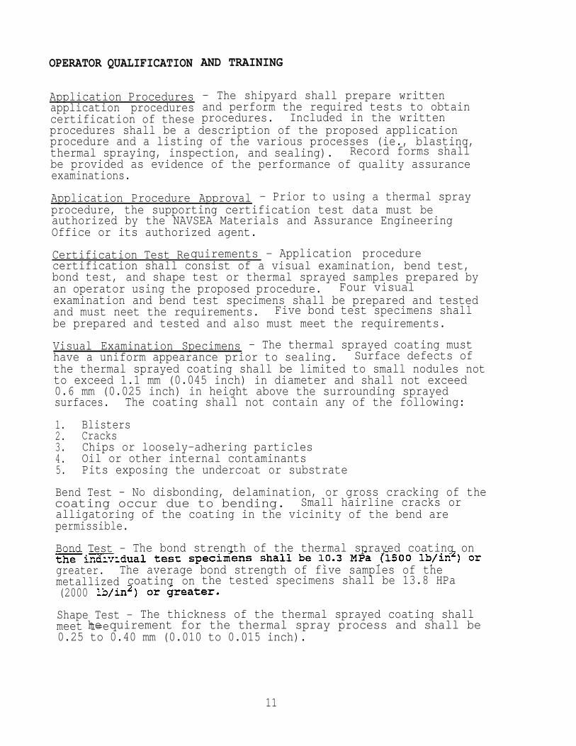
Certification Test Requirements - Application procedurecertification shall consist of a visual examination, bend test,bond test, and shape test or thermal sprayed samples prepared byan operator using the proposed procedure. Four visualexamination and bend test specimens shall be prepared and testedand must neet the requirements. Five bond test specimens shallbe prepared and tested and also must meet the requirements.
Visual Examination Specimens - The thermal sprayed coating musthave a uniform appearance prior to sealing. Surface defects ofthe thermal sprayed coating shall be limited to small nodules notto exceed 1.1 mm (0.045 inch) in diameter and shall not exceed0.6 mm (0.025 inch) in height above the surrounding sprayedsurfaces. The coating shall not contain any of the following:
1. Blisters2. Cracks3. Chips or loosely-adhering particles4. Oil or other internal contaminants5. Pits exposing the undercoat or substrate
Bend Test - No disbonding, delamination, or gross cracking of thecoating occur due to bending. Small hairline cracks oralligatoring of the coating in the vicinity of the bend arepermissible.
Bond Test - The bond strength of the thermal sprayed coating on
greater. The average bond strength of five samples of themetallized coating on the tested specimens shall be 13.8 HPa(2000
Shape Test - The thickness of the thermal sprayed coating shall he quirement for the thermal spray process and shall bemeet t=e0.25 to 0.40 mm (0.010 to 0.015 inch).
11

Certification of Thermal Spray Operators - Each operator shall becertified by demonstrating the ability to apply the specifiedcoating system using the applicable spray process, and correctand safe usage of the equipment.
Certification Test Requirements - Operator qualification shallconsist of a visual examination, bend test, bond test, and shapetest of thermal sprayed samples prepared by an operator. Four-
visual examination and bend test specimens shall be prepared andtested. Two shape test specimens shall also be prepared andevaluated.
Limits of Certification - Operators must certify separately foreach procedure they will use in production. An operator whocertifies a procedure by meeting the requirements becomescertified to spray to that procedure.
Retest of Operators - operator failing the initialcertification tests may perform one retest for each type of testfailed. If the operator fails the retest, the operator shall notbe certified until completion of retraining and subsequentcomplete certification retesting.
Term of Certification - Operator certification shall be retainedas long as Period of six months does not elapse betweenproduction use of the applicable thermal spray process.Production use is defined as performing thermal sprayingoperations at least eight hours in a consecutive day period.
Recertification Time Lapse Less Than Six Months - Operators whosecertification has lapsed may be recertified by satisfactorilycompleting the certification tests.
Certification Time Lapse Less Than Six Months - Visualexamination and bend tests are required if the operator has notperformed thermal spraying processes for a period of 30 days.
Certification Time Lapse Greater Than Six Months - Visualexamination, bend tests, and bond tests are required if theoperator has not performed thermal spraying processes for aperiod of six months.
Special - Recertification testing may also be required at anytime an operator’s performance is questionable as evidenced byproduction quality assurance.
Traininq - Puget Sound Naval Shipyard utilizes 40 hourspreparatory training prior to qualification. Total cost oftraining is $1,850 based on Shop 26 labor rate of $46.26 Per hourplus material (as of 3/90).
12
APPLICATION COSTS
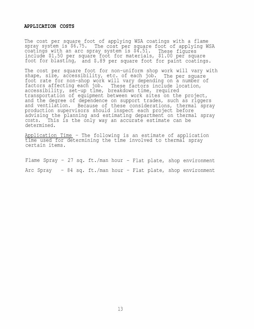
The cost per square foot of applying WSA coatings with a flamespray system is $6.75. The cost per square foot of applying WSAcoatings with an arc spray system is $4.51. These figuresinclude $1.50 per square foot for materials, $1.00 per squarefoot for blasting, and $.89 per square foot for paint coatings.
The cost per square foot for non-uniform shop work will vary withshape, size, accessibility, etc. of each job. The per squarefoot rate for non-shop work will vary depending on a number offactors affecting each job. These factors include location,accessibility, set-up time, breakdown time, requiredtransportation of equipment between work sites on the project,and the degree of dependence on support trades, such as riggersand ventilation. Because of these considerations, thermal sprayproduction supervisors should inspect each project beforeadvising the planning and estimating department on thermal spraycosts. This is the only way an accurate estimate can bedetermined.
Application Time - The following is an estimate of applicationtime used for determining the time involved to thermal spraycertain items.
Flame Spray - 27 sq. ft./man hour - Flat plate, shop environment
Arc Spray - 84 sq. ft./man hour - Flat plate, shop environment
13

MAINTENANCE, REPAIR METHODS AND COST
Thermal sprayed coatings that have been sealed can last yearswithout maintenance, even in a relatively aggressive environment.Coating maintenance is essential when the coating shows visiblesigns of sealant disintegration and before any corroding of themetal coating has begun.
Maintenance usually involves cleaning down and brushing to removecorrosion products and accumulated debris, and then overcoatingwith the same type of sealant or paint that was originally used.Maintenance may be performed at an earlier stage than this fordecorative reasons. Paint coatings designated for distinct coloreffects should be compatible with the original sealant applied.
When a thermal sprayed coating is damaged, exposing the coatingor the substrate, the following repair methods shall apply.
Surface Preparation, Small Areas - Surface preparation of smallareas (less than 100 square inches) shall be as follows:
Solvent clean as required.
Use a 1-inch, flexible blade, paint scraper and remove loosepaint around worn or damaged area to the boundary of wellbonded paint. Be careful to not gouge or further damage thethermal sprayed coating.
Vigorously brush away loose debris using a stiff, hand-held,nonferrous, bristle brush. Power tools should not be used asthey will polish smooth the thermal sprayed coating and maywear through the coating to the substrate.
Feather a 2 to 3 inch collar into the undamaged area.
Lightly abrade the feathered paint area around the exposedthermal sprayed coating with sand paper to provide a mechanicalbonding surface for the paint primer and sealer.
Surface Preparation Large Areas - Surface Preparation for largeareas (greater than 100 square inches) shall be as follows:
Solvent clean as required.
Abrasive brush blast away loose paint using aluminum oxide gritover the exposed thermal spray coated area. Low blastingpressures shall be used to minimize abrasion and removal ofthermal sprayed coating, but great enough for reasonable paintremoval and development of sufficient anchor tooth pattern forsealers and topcoat paints.
Feather a 2 to 3 inch collar into the well bonded paint area.
14

- Cosmetic differences between new and old paint can be minimizedby brush blasting or using sand paper and repainting the areabordered by a weld bead or a structural item.
Damage Exposing the Substrate - Surface preparation requiringpaint touch up shall be as follows:
- Solvent clean as required.
- Using a paint scraper, push the blade underneath the thermalsprayed coating to lift off all loosely bonded sprayed coatinguntil reaching a well bonded area.
Surface Preparation for Thermal Sprayed Coatinq Touch Up-Thermal sprayed coating touch up shall be accomplished asfollows:
- Solvent clean as required.
- Abrasive blast area to be repaired with 16-30 mesh aluminumoxide to white metal to give a 0.002” - 0.003” anchor tooth.
- Feather 2 to 3 inches into the good coating area.
- Apply thermal sprayed coating.
Sealinq and Topcoating Damaged Areas - When damage has exposedthe thermal sprayed coating or the thermal sprayed coating hasbeen replaced, sealing and topcoating shall be accomplished withproducts identical to or compatible with existing sealer/topcoat.
WSA Coating Removal - Grit blasting and grinding are currentlyrecognized as the methods for removal of wire sprayed aluminumcoatings. These methods are also recognized as havinglimitations. Grit blasting can not be accomplished in any spacewhere rotating machinery is located. Grinding is expensivebecause of the labor costs involved.
Removal of WSA coatings has been an area of concern whendiscussing the increasing usage of WSA as a corrosion controlmethod aboard US Naval ships. As a result, HAVSEA 07 taskedPuget Sound Naval Shipyard with investigating the feasibility ofcost effectively removing WSA coatings using high pressure waterjet technology. This project was accomplished over a two yearperiod. Reports (Thermal Spray Removal, Phase I and Phase II)were submitted to NAVSEA 07011 in FY-87 and FY-88.
The reports presented the results of a number of evaluations inaddition to establishing the feasillility of removing WSA coatingscost effectively using high pressure water jet technology.
15
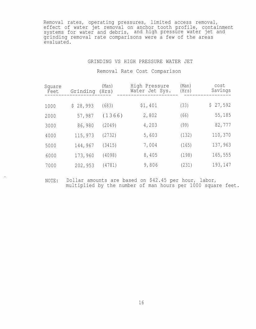
Removal rates, operating pressures, limited access removal,effect of water jet removal on anchor tooth profile, containmentsystems for water and debris, and high pressure water jet andgrinding removal rate comparisons were a few of the areasevaluated.
GRINDING VS HIGH PRESSURE WATER JET
Removal Rate Cost Comparison
Square (Man) High Pressure (Man) costFeet Grinding (Hrs) Water Jet Sys. (Hrs) Savings
------------------------ ---------------------- -----------------
1000
2000
3000
4000
5000
6000
7000
NOTE:
$ 28,993
57,987
86,980
115,973
144,967
173,960
202,953
(683) $1,401 (33) $ 27,592
(1366) 2,802 (66) 55,185
(2049) 4,203 (99) 82,777
(2732) 5,603 (132) 110,370
(3415) 7,004 (165) 137,963
(4098) 8,405 (198) 165,555
(4781) 9,806 (231) 193,147
Dollar amounts are based on $42.45 per hour, labor,multiplied by the number of man hours per 1000 square feet.
16

WIRE SPRAYED ALUMINUM
GENERAL INFORMATION
17

ALUMINUM COATING APPLICATION
The aluminum coating shall be applied in multiple layers and inno case shall less than two crossing passes, at right angles, bemade over every part of the surface. The sprayed aluminum shalloverlap on each pass to assure uniform coverage.
The steps in thermal spray application are as follows:
1. Grit blast.2. Thermal spray.3. Seal or paint.4. Drying time.
Thermal Spraying Technique - Follow gun manufacturersrecommendations for optimum spray distance. The angle of thespray stream to the surface shall be as close to 90 degrees aspossible and never less than 45 degrees. Accessories for the gunare available to maintain proper spray angles. When sprayingcomplex shapes, the operator shall mask and thermal spray tominimize over spray onto areas of the component where no coatingis desired. Cooling during the coating operation may beaccomplished by blasting clean dry air, carbon dioxide, or othersuitable gas near but not directly on the area being sprayed.The thermal spray operation shall be interrupted only to measurecoating thickness or temperature or to permit cooling to preventoverheating.
Cooling After Thermal Spraying - Under normal conditions, thecompleted work should be allowed to cool at room temperature at anormal rate before sealing. If required, accelerated coolingmaybe accomplished with a blast of clean dry air, carbondioxide, or other suitable gas. The air or gas shall bemaneuvered to obtain a uniform cooling rate over the entirethermal sprayed area. The component shall not be quenched withliquid to accelerate cooling.

WORKING AREA REQUIREMENTS
Abrasive Blasting Areas - If abrasive blasting is carried out inan enclosed area other than a designated blasting booth, the airin the enclosed area shall change at least once per minute.Additional safe breathing apparatus (operator’s hood) shall beused.
Spray Booths - The wet spray booth shall be constructed withsurfaces angled to deflect the thermal spray blast inward and notblow out of the booth. The booth shall be equipped with a wetcollector and an exhauster that will maintain air flow of atleast 200 cubic feet per minute per square foot of booth openinginto the booth entrance.
Enclosed Areas - Enclosed areas shall be equipped with a waterwash dust collector with a capacity in cubic feet per minute atleast three times the volume of the enclosed space. Air inletsto the areas shall be located near the ceiling on the sideopposite the working area. The air exhaust shall be located ator near the floor along the entire side of the room adjacent tothe working area. The duct work shall be large enough to permitair velocities greater than 2,000 feet per minute. An airrespirator mask shall be provided for the operator, as well aseye and ear protection.
Open Areas - Thermal spraying in open areas shall be carried outonly when suitable eye and ear protection and an air respiratorare being used.
19

SAFETY EQUIPMENT
Protective Equipment - The following protective equipment shallbe worn by the thermal spray operator.
1. Air line respirator.2. Noise protection (ear muffs and ear plugs).3. Eye protection for ultraviolet light.
Special Clothing - The following clothing is recommended whenblasting operations are performed in an enclosed space.
1. Helmet with forced air supply.2. Protective jacket.3. Protective trousers.4. Safety shoes.5. Rubber gloves.6. Protective shoe covers.
20

PAINT
21

PROCESSES
Paint shall be applied by spraying (conventional, airless, orelectrostatic), brushing, roller coating, dip coating, or filland drain coating.
22

SUBSTRATE PREPARATION
Proper surface preparation is a major factor in the performanceof paintfailurescleaningsurf ace.
coatings. It is estimated that 75 percent bf all paintare the result of inadequate surface preparation. Poorprevents the coating from bonding properly to the steelPeeling can result.
Selection of surface preparation shall be based on:
1. The nature of the substrate.2. Existing condition of the surface to be painted.3. Type of exposure.4. Past history of the surface to be presened.5. Practical limitations such as time, location, space, and
equipment availability.6. Economic considerations.7. Type of paint to be applied.8. Safety factors.
The initial cost of adequate surface preparation is justified dueto the increase in durability and maximum coating life with onlyminimal repairs and repainting to be performed.
The goal of surface cleaning is to provide a roughened surfacewhich is free of contamination and gouges or sharp projections.Surface contaminants must be removed to ensure coating adhesionand minimize the possibility of defects such as blistering,peeling, flaking, and underfilm rusting. Surfaces to be paintedfor preservation must be completely free of mill scale, rust,loose paint, dirt, oil, grease, salt deposits, and moisture. Toprevent imbedding contaminants during surface preparation, oil orgrease must be removed before using power tools or abrasive blastsurface preparation. Rusted surfaces shall be fresh waterrinsed, where practicable, to remove water soluble contaminantsbefore abrasive blasting or additional surface preparation byother means. Weld splatters and flux compounds should be removedby grinding or chipping.
Surface cleaning methods vary with the type of surfacepreparation needed, location, and size of area being cleaned.
After the surface has been properly cleaned, it must be abrasiveblasted to achieve a rough but uniform surface which is calledthe “anchor tooth". The pattern of roughening on the surfaceaffects paint adhesion and improves the ability of the paint tobond to the steel. The anchor tooth pattern is controlledprimarily by the shape and the hardness of the abrasive used.
The surface profile peaks should be approximately 1/3 as high asthe required coating thickness.
23
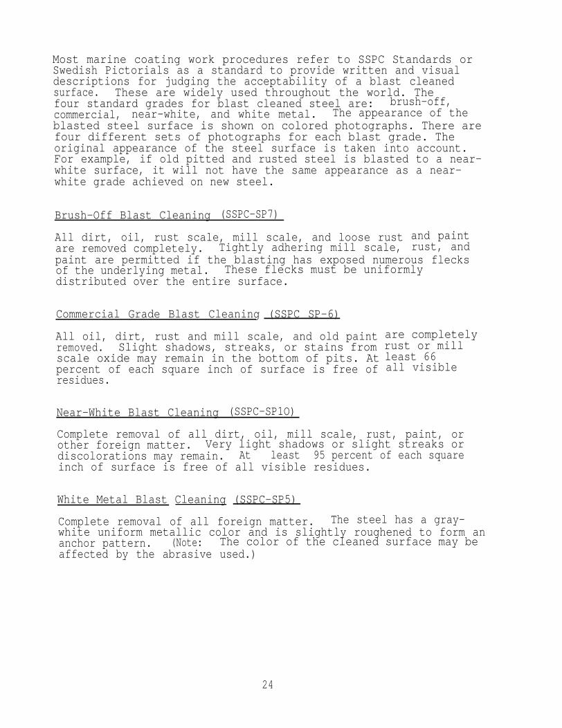
Most marine coating work procedures refer to SSPC Standards or Swedish Pictorials as a standard to provide written and visualdescriptions for judging the acceptability of a blast cleanedsurface. These are widely used throughout the world. Thefour standard grades for blast cleaned steel are: brush-off,commercial, near-white, and white metal. The appearance of theblasted steel surface is shown on colored photographs. There arefour different sets of photographs for each blast grade. Theoriginal appearance of the steel surface is taken into account.For example, if old pitted and rusted steel is blasted to a near-white surface, it will not have the same appearance as a near-white grade achieved on new steel.
Brush-Off Blast Cleaning (SSPC-SP7)
All dirt, oil, rust scale, mill scale, and loose rustare removed completely. Tightly adhering mill scale,
and paintrust, and
paint are permitted if the blasting has exposed numerous flecksof the underlying metal. These flecks must be uniformlydistributed over the entire surface.
Commercial Grade Blast Cleaning (SSPC SP-6)
All oil, dirt, rust and mill scale, and old paintremoved. Slight shadows, streaks, or stains fromscale oxide may remain in the bottom of pits. Atpercent of each square inch of surface is free ofresidues.
are completelyrust or millleast 66all visible
Near-White Blast Cleaning (SSPC-SP1O)
Complete removal of all dirt, oil, mill scale, rust, paint, orother foreign matter. Very light shadows or slight streaks ordiscolorations may remain. At least 95 percent of each squareinch of surface is free of all visible residues.
White Metal Blast Cleaning (SSPC-SP5)
Complete removal of all foreign matter. The steel has a gray-white uniform metallic color and is slightly roughened to form ananchor pattern. (Note: The color of the cleaned surface may beaffected by the abrasive used.)
24
PREFERRED APPLICATIONS
Information was gathered from the following 5P-3 membersfacilities regarding preferred paint systems, areas of
and/or
application, and how the paint coatings performed: InorganicCoatings, Puget Sound Naval Shipyard Painters (Shop 71), NAVSEA,National Steel and Shipbuilding Company, Integrated SystemsAnalysis, Ingalls Shipbuildingt Electric Boat Works, Newport NewsShipbuilding, Bay Shipbuilding Company, and Norfolk Shipbuildingand Dry Dock Company.
The results of this survey indicated that the epoxy polyamidepaint system is widely used by Naval and private shipyards.Areas of application are tanks, bilges, wet spaces, and exteriorsurfaces. This coating was stated to perform well but regularmaintenance is required for maximum coating performance.
Another widely used paint system in Naval shipyards on surfaceships and aircraft carriers is solvent-based inorganic zinc withepoxy polyamide topcoats. This system is being applied toexterior horizontal surfaces and waterways and exterior verticaland near vertical surfaces from six inches above the upperboottopping limit (in accordance with Naval Ships TechnicalManual, NAVSEA S9086-VD-STM-OOO/Chapter 631).
Private shipyards also use inorganic zinc with epoxy polyamidetopcoats for application on surface ships and tankers as acorrosion control method for topside areas.
According to the surveyed shipyards who are applying solvent-based inorganic zinc, this corrosion control system performs welland has an average life span of seven to ten years with littlemaintenance required. Various reports on inorganic zinc coatingsshow evidence of this coating system lasting for 15 to 20 yearsof service.
25

INORGANIC ZINC
Inorganic zinc primers provide years of corrosion free protectionto steel. Zinc coatings are protective in two different ways.They serve as a barrier and also as a galvanic protector of steelsurfaces.
When the zinc coating is first applied, it is a porous film ofzinc encapsulated in a silicate binder. In this state, moistureand oxygen penetrate the film, causing the zinc to corrode toprotect the substrate. This is part of the sacrificial actionwhich occurs. AS time goes on, the zinc corrosion products fillin all of the pores in the coating and the combination of theremaining zinc and the zinc corrosion products (which areinsoluble) form a permanent barrier coating. This barriercoating seals off the moisture and oxygen and the zinc stopscorroding. In this state, the coating represents the ultimatebarrier coating. The coating also retains its sacrificialproperties if and when the zinc and the substrate are exposed tomoisture and oxygen (ie., when the coating is damaged).
When damage occurs, all of the elements required for corrosionare present in the area of the damage and the zinc will sacrificeitself to protect the substrate. For a small damaged area (up to1/4 inch wide), the sacrificial action of the zinc will actuallyheal the damage with the zinc corrosion products. For largerdamaged areas, the sacrificial action of the zinc will preventcorrosion of the substrate until the damage can be repaired.Zinc coatings are also resistant to undercutting due to thechemical bond of the coating to the substrate.
Depending on the binder used, zinc primers can be classified aseither organic or inorganic. The use of zinc rich primers servesseveral purposes.
rich primers can be applied in the shop as a pre-construction primer, eliminating most of all field surfacepreparation.
2. Simplified coating systems. Zinc rich primers can betopcoated with a wide variety of industrial topcoats.
3. Minimized touch-up. Zinc rich primers are extremely toughand abrasion resistant.
4. zinc rich primers offer excellent resistance to corrosion,both as pre-construction primers and as topcoated primers incoating systems.
All inorganic zinc primers have excellent abrasion resistance,hardness, and toughness, but not flexibility.
26

Inorganic zinc primers are often used when a delay betweenpriming and topcoating is expected. They offer excellentprotection from corrosion and from handling damage. There isalso an advantage to aging an inorganic zinc primer beforetopcoating, because blistering will be minimized and so willtopcoat bubbling problems. When freshly applied inorganic zincis topcoated, it often blisters. Care should be taken to topcoatbefore major primer degradation and corrosion begins. Thegreater the thickness of the zinc primer (up to an optimumpoint), the longer the time before the underlying steel willbegin to corrode.
The appearance of a zinc coating is improved byof a suitable sealer coat. Guidance on type of
the applicationtopcoat to be
used should be obtained from the supplier of the zinc richcoating, especially if the surface is exposed betweenapplications. Members and assemblies coated with zinc richpaints may be handled or stacked as soon as the coating is dry,but exposure to freshly applied zinc silicate paints to moisturewithin a stack can result in deleterious changes.
Inorganic zinc paint is usually furnished as a two-part system,paint base and zinc pigment. The two partsprior to use. Thorough mixing is importantconsistent application. Paint must also beduring application.
should be mixed justfor a uniform,mixed periodically
27

EPOXY POLYAMIDE
Epoxy polyamide coatings are similar to other epoxy coatings inthat they consist of a two-component system that includes apigmented polyamide resin (A component) and an epoxy resin (Bcomponent). Once they are mixed together and applied as a paintfilm, the coating cures to a hard film by chemical conversion.During this curing period, the solvents used to maintain thecomposition in liquid form are released by evaporation.
The epoxy polyamide paint system is used as the standard topcoatsystem (MIL-P-24441). This paint is designed to provide adurable, hard, chemical-resistant, non-porous coating which isvery resistant to the marine environment. It can be appliedunder conditions of dampness and coldness (down to 35 degrees F)where few other coatings will adhere.
In order to be used under these conditions, it is necessary thata good job of surface preparation be done. Surfaces to be coashould be completely free from rust, loose paint, dirt, scale,oil, grease, salt deposits, moisture, and other contaminants.is also necessary to carefully follow mixing and applicationinstructions in order for the coating to be successful undersevere conditions.
thatted
The Navy epoxy polyamide Coating (MIL-P-24441) consists of sevenindividual formulations, Formulas 150 through 156. Thesecoatings are suitable for use in tanks, bilges, wet spaces, andon exterior surfaces.
28
PARAMETERS AND LIMITATIONS
Specific paint parameters are indicated by the manufacturer'sapplication instructions. The following parameters andlimitations areCH-3.
General
Paint shall not
derived from Process Instruction
be applied over mill scale, rust,
No. 0631-216A
loose paint,dirt, scale, oil, grease, salt deposits, and moisture (except-
application over minor quantities of mill scale and residual rustin the crater of pits when hand preparation prior to “touch up”painting is authorized).
Paint shall not be applied when the air temperature is expectedto drop to 32°F or below before the paint has dried. Paintshould not be applied when the surrounding air temperature isbelow 40°F.
Paints should not be applied when metal surface temperatures arePaint shall not be
applied to wet or damp surfaces or in rain, snow, fog, or mist.
Any applied paint exposed to freezing, excess humidity, rain,snow, or condensation shall be permitted to dry. Damaged areasof paint should then be removed and the surface again prepared,inspected, and then repainted with the same number of coats andtype of paint as the undamaged areas.
If paint is applied in damp or cold weather, the metal should bepainted under cover (ie., protected, sheltered) with thesurrounding air and the metal heated to at least the temperaturespecified above. In all such cases, the required temperature andhumidity conditions should be met. Such metal should remainunder cover or be protected until dry or until weather conditionspermit its exposure.
All corners, crevices, rivets, bolts, uncontoured welds, andsharp edges shall receive a brush coat of paint preferably beforethe metal receives the first full prime coat or before the lastfinish coat of paint. If possible, allow this brush coat to dryto the touch prior to application of the full prime coat or thenext full coat of paint. Apply the full prime coat to ferrousmaterials as soon as possible to prevent “flash” rusting.
Painters should use wet film thickness (WFT) gauges periodicallyduring coating application to monitor the thickness of theapplied wet film. The equipment and painter technique shall beadjusted to apply a WFT which will dry or cure to the desiredminimum dry film thickness (DFT). However, excessive WFT shallbe avoided to reduce solvent entrapment in the dried coating.Painter use of WFT gauges and the comparison of WFT measurements
29

to resulting DFTfilm applicationDFT.
measurements will aid in a more accurate wetand less rework required to obtain a minimum
Each coat of paint, to the maximum extent practical, shall beapplied as a continuous film of uniform thickness free of pores.Any thin spots or areas missed in the application shall berepainted and permitted to dry before the next coat of paint isapplied.
30
APPLICATION OF PAINT COATINGS
The following list of shipboard equipment and accessories as ageneral rule shall not be painted. It is provided as generalguidance information.
General
1.
2.
3.
4.
50
6.
7.
8.
9.
10.
11.
12.
13.
14 l
15.
16.
CRES decks,spaces.
Decorativetops l
CRES galley equipment, and
plastic surfaces such as on
CRES bulkheads in wet
bulkheads or table
Dogs or operating gear of watertight doors, hatches,scuttles and similar items.
Hatch and door rubber gaskets; rubber window moldings.
Identification plates.
Knife edges of watertight doors
Porcelainized bulkheads.
Threaded parts.
Anodes and cathodic protectors.
The following interior surfaces
and hatches.
constructed of aluminum:
a. Bins, shelves, dressers, cabinets, battens and fittings.
b. Interior gratings, handrails, and floor plates.
c. Internal surfaces of ventilation ducts.
Activating mechanisms of electrical safety devices andcontrol switchboards on machinery elevators.
Bell pulls, sheaves, annunciator chains, and othermechanical communication devices.
corrosion resisting steel piping and components in ship’sinterior compartments (except non-nuclear piping/componentsin bilge and tank areas).
Composition metal water ends of pumps.
Condenser heads and outside surfaces of condensers when ofcomposition metal.
Dry sprinklingholes drilled
piping within magazines of the type havingin the pipe top.
31

17.
18.
19.
20.
21.
22.
23.
24.
25.
26.
27.
28.
29.
30.
31
32.
33.
34.
Exposed composition metal part of any machinery.
Glands, stems, yokes, toggle gear, and all machined externalparts of the valve.
Heat exchange surfaces of heating or cooling equipment.
Joint faces of gaskets and packing surfaces.
Lubricating gear, such as oil holes, oil or grease cups,lubricators, and surfaces in contact with lubrication oil.
Lubricating oil reservoirs.
Machined metal surfaces of reciprocating engines or pumpsand all "oil wetted” surfaces of internal combustionengines.
Metal lagging.
Rods, gears, universal joints and coupling of valveoperating gear.
Expansion joints, pipe hangers, flexible hose connections,items partially fabricated of rubber and resilient elementsof isolation mounts.
Sliding feet of turbines and boilers.
Springs.
strainers.
Turbine casing joints, nuts, and bolts.
Working surfaces.
Deck fittings and joiner hardware on plastic boat.
Light reflecting and transmitting surfaces of items such aslight fixtures, ports, and windows.
Sea chest waster rings.
The above items should be covered, masked, or otherwise protectedfrom paint application.
32
QUALITY ASSURANCE
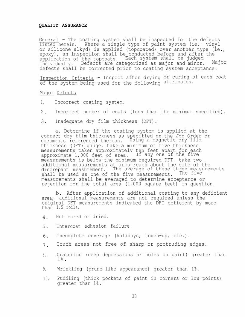
General - The coating system shall be inspected for the defectslisted herein. Where a single type of paint system (ie., vinylor silicone alkyd) is applied (topcoated) over another type (ie.,epoxy), an inspection shall be conducted before and after theapplication of the topcoats. Each system shall be judgedindividually. Defects are categorized as major and minor. Majordefects shall be corrected prior to coating system acceptance.
Inspection Criteria - Inspect after dryingof the system being used for the following
or curing of each coatattributes.
Major Defects
1. Incorrect coating system.
2. Incorrect number of coats (less than the minimum specified).
3. Inadequate dry film thickness (DFT).
a. Determine if the coating system is applied at thecorrect dry film thickness as specified on the Job Order ordocuments referenced thereon. Using a magnetic dry filmthickness (DFT) gauge, take a minimum of five thicknessmeasurements taken approximately ten feet apart for eachapproximate 1,000 feet of area. If any one of the fivemeasurements is below the minimum required DFT, take twoadditional measurements at arms reach about the site of thediscrepant measurement. The average of these three measurementsshall be used as one of the five measurements. The fivemeasurements shall be averaged to determine acceptance orrejection for the total area (1,000 square feet) in question.
b. After application of additional coating to any deficientarea, additional measurements are not required unless theoriginal DFT measurements indicated the DFT deficient by morethan
4.
5.
6.
7.
8.
9.
10.
1.5 roils.
Not cured
Intercoat
or dried.
adhesion failure.
Incomplete coverage (holidays, touch-up, etc.).
Touch areas not free of sharp or protruding edges.
Cratering (deep depressions or holes on paint) greater than1%.
Wrinkling (prune-like appearance) greater than 1%.
Puddling (thick pockets of paint in corners or low points)greater than l%.
33

11.
12.
13.
Contaminants in film (sand, dirt, water, oil, debris)greater than 1%.
Wrong color (exterior weather boundaries or habitabilityspaces).
Other conditions which will result in premature failure ofcoating system.
Minor Defects
1. Cratering less than 1%.
2. Wrinkling less than 1%.
3. Puddling less than 1%.
4. Contaminants less than 1%.
5. Other conditions not considered normal but not consideredbe defects which will result in premature failure of thecoating system.
Inspection Equipment
to
Mikrotest thickness gauges or other NAVSEA approved gauge shallbe utilized by inspecting personnel to determine the DFT applied.Correction tables shall be established and accompany each gaugefor the different steel alloys typically encountered duringtesting. Tables indicating gauge error at typical millagethicknesses encountered shall accompany each-gauge.
Dry film thicknesses of coatings applied to aluminumcan be obtained by use of “Demitron" electromagneticgauge or by coating steel coupons during the processtaking DFT readings from the coupons.
substratesthicknessof work and
34

OPERATOR
Painters
QUALIFICATION AND
at Naval shipyards are not given specific paintqualifications. Painters that are inexperienced or-newly hiredare assigned to work with a mechanic for an average of two tothree years in order to gain valuable experience needed in thetrade. During this time, they are assigned jobs such as masking,sanding, and descaling to prepare areas for paint application.
Painters must be experienced at performing the following traderelated tasks before they are assigned actual paint applicationjobs.
1.
2.
3.
4.
5.
6.
7.
8.
Ability to set up and properly adjust and maintainequipment.
Prepare surfaces to be painted.
Protection of components in paint application areas.
Proper application of paint coatings per processinstructions, technical manuals, and manufacturersspecifications.
Correct use of paint thinners.
Protection of area to be painted from fire hazards.
Coordinate work with other trades.
Show ability to work with minimum or no supervision.
35

APPLICATION COSTS
The following information is based on average rates obtained fromNational Steel and Shipbuilding Company in San Diego, Californiaand the Planning and Estimating Department at Puget Sound NavalShipyard in Bremerton, Washington. The figures reflect the costestimates for non-uniform (ie., non-flat) surfaces with a varietyof accessibilities for the painter and sandblaster.
Epoxy Polyamide = $1.24 per square foot(Mare Island series)
Inorganic Zinc/Epoxy(Mare
Polyamide = $1.60 per square footIsland)
36
MAINTENANCE AND REPAIR METHODS
Maintenance of Inorganic Zinc Coatings - Maintenance costs of theinorganic zinc with epoxy topcoats would be minimal.topcoat should be applied as required to avoid the initiation ofincipient corrosion. The life of the original coating would varydepending on the severity of the exposure, but in a mildenvironment, the first recoat would probably not be required for15 to 20 years.
It is recommended that these coatings be evaluated on a regularbasis so that a fresh topcoat can be applied before ansubstantial degree of failure is experienced in the coatingsystem. Attention should also be paid to any small areas ofpoint fracture so that they may be quickly repaired. These areaswill be small because they metallize. Zinc coating will tend toinhibit or prevent undercutting and delamination.
Preparation of painted surfaces includes the removal of surfacecontaminants, corrosion, old paint, moisture, blending (touch-uppaint), and roughening of the surface (old paint in goodcondition).
Recleaning is necessary before touch-up or re-coating work isperformed. Damage to a coating on board ship can occur in anumber of ways: burns from welding, chipping from metal tools,and equipment or scaffolding being dragged across painted steelsurfaces. Any kind of damage to the paint film must be repairedto prevent corrosion attack at the exposed areas.
Repair of Localized Areas - It is imperative that removal of theold paint is carried back around the edges of the area or spot tobe repaired until an area of completely intact and adheringpaint, free of blisters and underlying rust, is attained. Theedges of the tightly adhering paint surrounding the area to bere-coated must be feathered, with no sharp edges, to allow properblending and prevent laying new paint over loose or crackedpaint. Areas of intact paint to be overcoated must first beroughened (ie., brush blasting or light sanding) and a tack coatshould then be applied.
When evidence of corrosion, peeling, blistering, scaling, orgeneral disintegration is apparent, the paint should be removeddown to the bare surfaces. Removal of the paint coating may beperformed by a variety of methods of which the nest common areabrasive blasting, water blasting, grinding, descaling, wirebrushing, and needle guns. The removal method depends upon thearea of the ship to be painted and the type of paint beingapplied.
Old paint which is still in good condition provides an excellentbase for repainting. The surface shall be roughened, cleaned,and dried before new paint is applied. When painting overpreviously painted steel and an application of an intermediate
37

topcoat is performed, any contaminants remaining on the first---coat will interfere with the bonding of the newly applied paintcoating. Inter-coat cleanliness can be achieved by removingdust, oil spots, chalking, markings, and spills.
Paint that is visibly cracked, loose, or flaking must be totallyremoved before repainting. Old layers of unsound or dead paintwill lift from the surface and will cause the new paint to crack.As a result, delamination or peeling of large layers of paintwill occur.
Coating Over Inorganic Zinc Coatings
If epoxy coatings are applied over aged inorganic zinc coatings,or if the topcoat over an inorganic zinc coating has been removedby mechanical damage, the inorganic zinc coating should bescrubbed and washed with a detergent solution. Flush the cleanedsurface with fresh water to remove loosened dirt, grime, andcleaning solution. Allow surface to dry. Lightly roughen thedry surface by mechanical means, feathering the edges of theintact topcoat. Reapply the topcoat system. Apply the firstcoat of the topcoat system as a thin film, coating the inorganiczinc, and allow to dry. This fills the pores and seals thesurface of the inorganic zinc coating. Follow this procedurewith the complete topcoat system.
38

PAINT
GENERAL INFORMATION
39

GENERAL ADVANTAGES
that should beThe general advantages of paint coatingsconsidered when choosing a protection system are:
1.
2.
3 .
4.
5.
Ease of application in shop or on site.
Wide availability of painting facilities.
No effect on the mechanical properties ofsubstrate (this is true of sprayed metal
Easy repair of coatings.
the steelcoatings also).
Wide range of colors available for cosmetic purposes.
40
SURFACE
Certain
PREPARATION LIMITATIONS
surface conditions that are frequently encountered onboard ships must be corrected prior to coating application.These surface conditions consist of the following.
Sharp Edges - Will cause paint to draw thin. The edges should beground to smooth edges.
Inside Corners - Provide a collection point for excess paint.Inside corners should be welded and ground to form a smooth,rounded inside contour. The coating shall be properly sprayed inorder to prevent thick, cracked, and spongy deposits of paint.
Other - Metal splinters, weld splatter, etc. should be groundflush. Crevices and pits should be filled with weld metal andground flush to the surface.
41

CURING OR DRYING AND RECOAT
Each coat of paint shall bebefore the application of a
TIMES
in a proper state of cure or drynesssucceeding coat (recoat time).
The normal recoat times between succeeding coats of epoxypolyamide (MIL-P-24441) formulas are 24 hours at 50-60 degrees F;16 hours at 60-80 degrees F; and 6-8 hours at 80-90 degrees F.Although a longer time can be allowed between succeeding coats,it is desirable to recoat within 24 hours to reduce thepossibility of surface contamination.
If epoxy primed or intermediate coated surfaces becomecontaminated, surface shall be cleaned with water and detergent,and solvent if required, rinsed with fresh water and then apply atack coat (l-2 wet mils), of the same material as the last coatapplied, before application of the succeeding full coat of epoxy.A tack coat shall also be applied when intact epoxy has beenbrush blasted or roughened to serve as a base coat for theapplication of additional epoxy coats.
42

VOLATILE ORGANIC COMPOUNDS (VOC)
The volatile organic compoundthat were tested in the 2,360are as follows:
International Brand “FP"VOC grams per liter
(VOC) levels of the paint systemshour accelerated salt spray booth
Series (Epoxy Polyamide)= 190
Commercial Inorganic Zinc (International Brand) VOC grams
Inorganic ZincVOC grams
per liter = 430
(Navy Specification)per liter = 540
TYPE I Mare Island System (Military Exterior Topcoat):
MIL-P=24441/l Epoxy Polyamide (Formula 150) GreenVOC grams per liter = 347
MIL-P=24441/2 Epoxy Polyamide (Formula 151) Haze GrayVOC grams per liter = 365
TT-E-490 Enamel Exterior Topcoat (Gray)VOC grams per liter = 380
Currently, these are the systems being used with the guidelinesset forth in the State of Washington. The International brand“FP” series (epoxy polyamide) falls within California VOCcompliance regulations. The Navy has until September 1, 1991 tomake these paint formulas fall within 340 VOC grams per liter forVOC compliance.
43
WIRE SPRAYED ALUMINUM AND PAINT
EQUIPMENT AND MATERIAL COSTS
AND CONSUMABLES
The following information is provided withthe understanding that Puget Sound Naval Shipyardis not endorsing any single manufacturer orproduct and that said information is to be usedonly as a guide to possible sources and theapproximate pricing of these products.
44

EQUIPMENT AND MATERIAL COSTS
Much of the equipment and many of the consumable items are usedin both thermal spray and paint facilities. The following listis a combination of these items and utilizes the followinglegend. (P) = paint FacilitY, (TS) = Thermal Spray Facility, and(B) = Both Paint and Thermal Spray Facilities.
A.B.C.D.E.F.G.H.I.J.K.L.M.N.O.P.QR.S.T.U.v.w.x.Y.Z.AA.BB.CC.DD.EE.FF.GG.
Vapor Degreaser (P)Containerized Abrasive Blast Unit (B)WSA Spray Equipment (TS)Arc Spray Equipment with Running Gear and Angle Nozzle (TS)Water Wash BOOth (B)Paint Spray Equipment (p)Paint Mixers (P)Control Console/Power SupplY - Electrostatic Spray (P)Powder Spray Gun - Electrostatic Spray Powder (P)Powder Hopper/Feeder - Electrostatic Spray Powder (P)Powder Spray Booth - ESP (Cartridge Type) (p)Oven: Curing Type, Walk-In (B)Storage Cabinet (B)Flammable Liquid Storage Cabinet (B)Pre-Expended Bin Storage (B)Small Parts Storage (B)Oxygen and Acetylene Bottle Storage Racks (TS)Work Table (B)One-Ton Electric Hoist and Swing Boom (3)Half-Ton Hand-Operated Chain Hoist (B)Mobile Hydraulic Floor Crane (Engine Hoist) (B)Hydraulic Pallet Truck (B)Platform Truck (3)Surface Profile Measurement Apparatus (B)Portable Electric Psychrometer (B)Holiday Detector (Portable) (P)Wet Film Thickness Gauge (p)Dry Film Thickness Gauge (P)Air Compressor and Dryer (P)Battery Operated Hand Truck (B)Direct Current power Source (450 and 650 Amp) (TS)Water Jet Removal System (B)Site Containerized Thermal Spray Facility (TS)
45
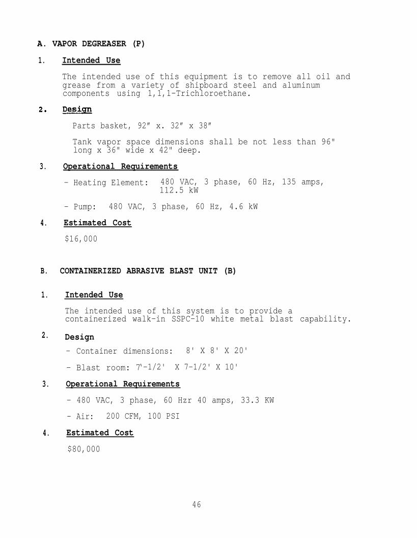
A. VAPOR DEGREASER (P)
1. Intended Use
The intended use of this equipment is to remove all oil andgrease from a variety of shipboard steel and aluminumcomponents using 1,1,1-Trichloroethane.
Parts basket, 92” x. 32” x 38”
Tank vapor space dimensions shall be not less than 96"long x 36" wide x 42" deep.
3. Operational Requirements
- Heating Element: 480 VAC, 3 phase, 60 Hz, 135 amps,112.5 kW
- Pump: 480 VAC, 3 phase, 60 Hz, 4.6 kW
4. Estimated Cost
$16,000
B. CONTAINERIZED ABRASIVE BLAST UNIT (B)
1. Intended Use
The intended use of this system is to provide acontainerized walk-in SSPC-10 white metal blast capability.
2. Design
- Container dimensions: 8' X 8' X 20'
- Blast room: 7‘-1/2' X 7-1/2' X 10'
3. Operational Requirements
- 480 VAC, 3 phase, 60 Hzr 40 amps, 33.3 KW
- Air: 200 CFM, 100 PSI
4. Estimated Cost
$80,000
46

C. WSA SPRAY EQUIPMENT (TS)
1. Intended Use
Equipment is to be used to apply corrosion resistantcoatings, such as aluminum and zinc, in the form of a moltenmetal spray developed from a metal wire using oxygen-acetylene.
MIL-M-3800D lists items to be provided in metallizingsystem. The major items are listed. Additionalrequirements and remarks are noted where applicable.
EQUIPMENT
Metallizing Gun Wire fed, air turbine or airmotor wire device. Themetallizing gun must producehigh quality coatings whileoperating within the 15 psimaximum allowable acetylenepressures specified by thesafety codes. The gas head andcylinder valve for controllingthe mixture of oxygen, air,and acetylene must have “O-ring” fits for ease o: PM\CMand prevention of galling andfreezing from prolongedstorage and use in lowtemperatures. Add flow rateand pressure envelope number.Lubrication sight plugrequired for checking gearcase Lubricant.
Carrying Case
Manuals, parts lists,diagrams
Air Caps
Wire Nozzles
Hose Set
operator manuals, illustratedparts breakdown, indexed to aparts/stock number List,system assembly/operatingdiagrams andpreventive/correctivemaintenance instructions.
Circular and elliptical spraypatterns.
Federal Specification ZZ-H-461
47

C. WSA SPRAY EQUIPMENT (TS)(Continued)
Oxygen Regulator
Fuel Gas Regulator
Oxygen Flow Meter
Fuel Gas Flow Meter
Air Flow Meter
Air Control Unit
Wire Reel and Stand
Wire Straightener
Gun Mounting Fixture
Flame Arrester
Angular Air Caps
Gun Extension
Utility Requirements
- 30 CFM at 65 PSI
1.4 M3 per HR Acetylene
4. Estimated cost
$4,500
UL-252, Table III of MIL-M-3800D
U1-252, Table III of MIL-M-3800D
Design per MIL-M-3800
Design per MIL-M-3800
Design per MIL-Z4-3800
Preserved with wire sprayedaluminum per DOD STD 2138(SH)
Not required
To produce a 45 degreedeflection of the spray.
l-foot extension capable ofoperating with and without a45 degree deflection angularair cap.
48

D.
1.
2.
E.
1.
2.
3.
4.
ARC SPRAY EQUIPMENT WITH RUNNING GEAR AND ANGLE NOZZLE (TS)
Intended Use
Equipment is to be used to apply corrosion resistantcoatings, such as aluminum, using an electric arc as thesource of heat between two consumable wires. Compressed airor inert gas is used to propel molten metal onto thesubstrate.
EQUIPMENT
Wire Feed Assembly
Spray Gun Assembly
Electrical Assembly
l/8N Wire Drive Kit (includes feed rolls,contact tips, electronic parts)
Estimated Cost
$13,110
WATER WASH BOOTH (B)
Intended Use
The water wash spray booth is a partially enclosed structuredesigned to removefumes generated by
Design
- Water wash boothwide x 8' high x
airborne metallic particles, dust, andthe metal spray process.
working dimensions shall be nominally 10'10' deep.
Utility Requirements
- Fan: 480 VAC, 60 Hz, 3 phase, 15 amps, 22.5 kW
- Pump: 480 VAC, 60 Hz, 3 phase, 12 amps, 10 kW
- Water: 10 GPM
Estimated Cost
$11,000
49
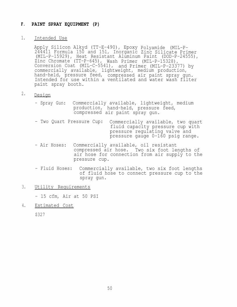
F.
1.
2.
3.
4.
PAINT SPRAY EQUIPMENT (P)
Intended Use
Apply Silicon Alkyd (TT-E-490), Epoxy244411 Formula 150 and 151, Inorganic
Polyamide (MIL-P-Zinc Silicate Primer
(MIL-P-15929), Heat Resistant Aluminum Paint (DOD-P-24555),Zinc Chromate (TT-P-645), Wash Primer (MIL-P-15328),Conversion Coat (MIL-C-5541), and Primer (MIL-P-23377) bycommercially available, lightweight, medium production,hand-held, pressure feed, compressed air paint spray gun.Intended for use within a ventilated and water wash filterpaint spray booth.
Design
- Spray Gun: Commercially available, lightweight, mediumproduction,compressed
- Two Quart Pressure Cup:
hand-held, pressure feed,air paint spray gun.
Commercially available, two quartfluid capacity pressure cup withpressure regulating valve andpressure gauge 0-160 psig range.
- Air Hoses: Commercially available, oil resistantcompressed air hose. Two six foot lengths ofair hose for connection from air supply to thepressure cup.
- Fluid Hoses: Commercially available, two six foot lengthsof fluid hose to connect pressure cup to thespray gun.
Utility Requirements
- 15 cfm, Air at 50 PSI
Estimated Cost
$327
50
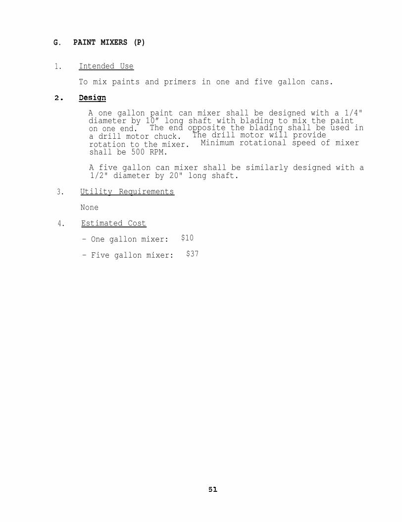
G. PAINT MIXERS (P)
1. Intended Use
To mix paints and primers in one and five gallon cans.
A one gallon paint can mixer shall be designed with a 1/4"diameter by 10” long shaft with blading to mix the painton one end. The end opposite the blading shall be used ina drill motor chuck. The drill motor will providerotation to the mixer. Minimum rotational speed of mixershall be 500 RPM.
A five gallon can mixer shall be similarly designed with a1/2" diameter by 20" long shaft.
3. Utility Requirements
None
4. Estimated Cost
- One gallon mixer: $10
- Five gallon mixer: $37

H.
1.
2.
3.
I.
1.
2.
3.
CONTROL CONSOLE/POWER SUPPLY - ELECTROSTATIC SPRAY (P)
Intended Use
Houses all electrical and air inputs, powder feed and highvoltage controls, gauges and switches for a complete singlegun electrostatic spray system.
Design
- Chassis size, 18" x 18" x 10", typical
- Console shall be wall or cart mounted
Operational Requirements
- Electrical, typical
Input 120/240 VAC, 60 HZoutput 30-90 KVCurrent (short circuit) 150 MicroAmperes
- Pneumatic, typical
Input Air 60-100 psiTotal Air Consumption 15 SCFM
- UC can only be used with sameand powder hoppers
POWDER SPRAY GUN - ELECTROSTATIC
manufacturer’s spray guns
SPRAY POWDER (P)
Intended Use
For the manual application of electrostatically sprayedpowder coatings.
Design
- The spray gun shall be less than 2 lbs. in weight
- The gun
- The guncoating
barrel shall be designed for ease of cleaning
shall have lance extensions of 6' and 12' forinterior areas
Operational Requirements
The gun manufacturer shall be the same for the controlconsole and powder hopper. Interchangeability is notacceptable.
52

J.
1.
2.
3.
4.
POWDER HOPPER/FEEDER
Intended Use
- ELECTROSTATIC
As a portable container to hold andpowder spray gun.
SPRAY POWDER (P)
feed powders for the
Powder capacity of 50 lbs.
The hopper/feeder shall be equipped with a venturi systemto transfer powder to spray gun
Two additional hopper/feeders of 6-8 lb capacity shall beprovided
The 6-8 lb hopper/feeders shall have a size of35" x 15" x 15", typical.
Operational Requirements
- The pneumatic requirements of the hopper/feeder shall bein the ranges of:
Hopper Fluidizing Air 3-4 SCFM 5-15 psiEjection Air 4-6 SCFM 40-100 psiDilution Air 4-6 SCFM 40-100 psi
Estimated Cost
Powder Spray System(control console/power supply/spray gun/hopper/feeder)
$4,186
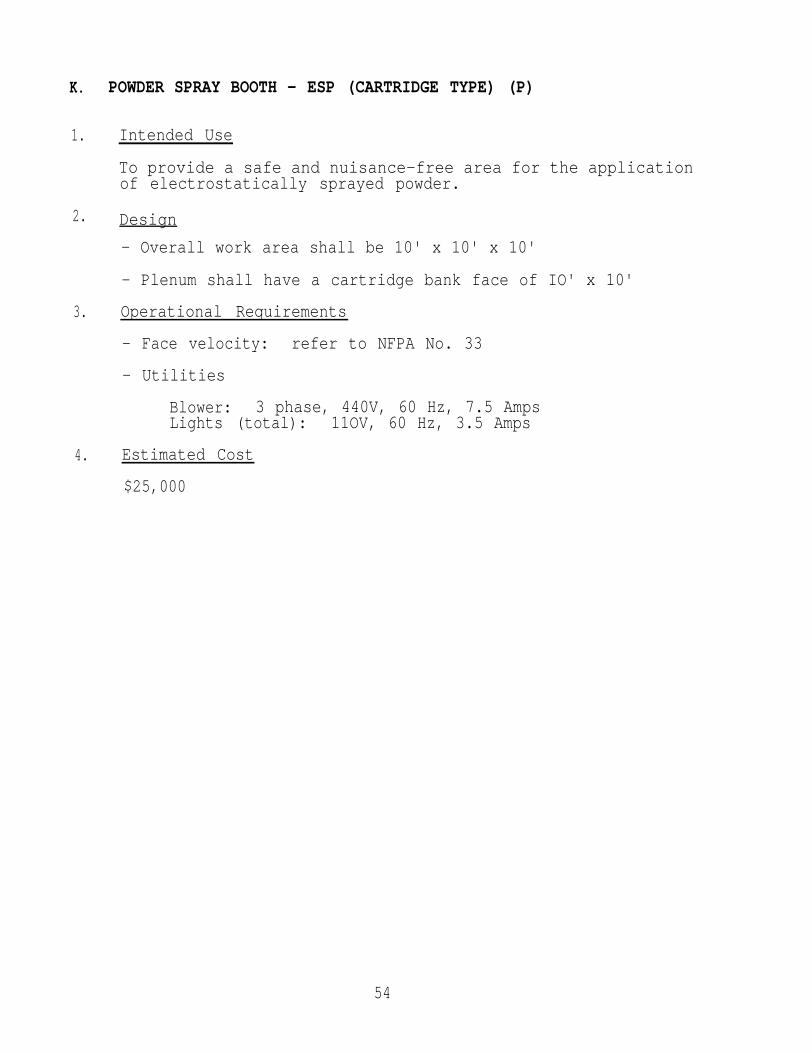
K. POWDER SPRAY BOOTH - ESP (CARTRIDGE TYPE) (P)
1. Intended Use
To provide a safe and nuisance-free area for the applicationof electrostatically sprayed powder.
2. Design
- Overall work area shall be 10' x 10' x 10'
- Plenum shall have a cartridge bank face of IO' x 10'
3. Operational Requirements
- Face velocity: refer to NFPA No. 33
- Utilities
Blower: 3 phase, 440V, 60 Hz, 7.5 AmpsLights (total): 11OV, 60 Hz, 3.5 Amps
4. Estimated Cost
$25,000
54
L OVEN; CURING TYPE, WALK-IN (B)
1. Intended Use
To provide uniform heating to parts that have to beelectrostatically powder coated so that the coating willflow and cure to a smooth hard finish. The oven shall alsobe used for preheating parts.
2. Design
- Work space: 84" wide x 120" deep x 84" high
3. Operational Requirements
- Oven shall have the operational range of 100-450°F.
- With the 450°F limit, the oven shall be set on a concretefloor. The oven heating area will not have its own floor.
- Utilities
Heat source:
Electric Oven 3 phase, 440V, 140 KW, MaximumRecirculation System 3 phase, 440v, 12 Amps, Maximum
4. Estimated Cost
$38,000
M STORAGE CABINET (B)
1. Intended Use
The intended use of this cabinet is to store nonflammablesupplies for use in an industrial environment.
2. Design
18" deep as a minimum.
3. Utility Requirements
None
4. Estimated Cost
$288
55

N.
1.
2.
3.
4.
0.
1.
2.
3.
4.
FLAMMABLE LIQUID STORAGE CABINET (B)
Intended Use
The intended liquids.
Design
use of this cabinet is to store volatile
Cabinet shall be of double-wall construction.
Cabinet shall contain vapor vent openings equipped withremovable screw caps protected by flash arrester.
Minimum 2" deep leak proof pan bottom.
Internal cabinet dimensions shall be 30" x 18" x 60"minimum.
Utility Requirements
None
Estimated Cost
$591
PRE-EXPENDED BIN STORAGE (B)
Intended Use
The intended use of this unit is to provide storage offastener assemblies, classified by material and size.
Design
- Shelving shall be 36" wide x 12" deep x 75" high.
Bins shall be 6" wide x 12" deep x 4" high.
Bins shall have and handle and label holder.
Utility Requirements
None
Estimated Cost
$184
56

P. SMALL PARTS STORAGE (B)
1. Intended Use
2.
The intended use of this cabinet is to store small rubberplugs and miscellaneous masking supplies.
Design
- Dimensions shall be at a minimum 16-1/2" deep x 35" high x2511 wide.
3. Utility Requirements
None
4. Estimated Cost
$251
Q.
1.
2.
3.
4.
OXYGEN AND ACETYLENE BOTTLE STORAGE RACKS (TS)
Intended Use
To provide upright protection for high pressure gascylinders (particularly the neck and valve assemblies) whiletransporting and during use.
Design
- Rack capable of holding 8 oxygen or 6 acetylene bottles.The racks will be constructed such that the storage rackcontaining bottles maybe used to lift and load thebottles onto a vehicle for transportation.
- The rack shall have a door/band or bar tO hold the bottlesin place.
- A padlock hasp or locking device shall secure the bottles.
Requirements
Estimated
$500
Cost
57

R. WORK TABLE (B)
1. Intended Use
General purpose, commercially available, work table for usein Corrosion Control Shop for masking, assembly,disassembly, and various repair functions.
2. Design- 6' length x 29" width x 33-1/21" (+/- 1/2") height steeltop work table supported by steel leg assembly, stringerand shelf.
3. Utility Requirements
None
4. Estimated Cost
$199
S. ONE-TON ELECTRIC HOIST AND SWING BOOM (B)
1. Intended Use
TO lift heavy objects from an equipment cart,remove product from the degreaser and return
2. Design
- Capable of lifting and lowering 2,000 pounds a height of15 feet and moving the load along an I-beam trolley.
- Load hook shall be a swivel type and must be fitted with asafety device to bridge the throat opening. Hook throatopening shall be 29/32 inch minimum.
- Motor speed governor shall limit lowering speed to 10 feetper minute.
: Utility Requirements
- 480 VAC, 3 phase, 60 Hz, 4 amps, 3.33 KW
4. Estimated Cost
Swing Boom $ 858Hoist, Trolley & Chain Container $1,462
------TOTAL $2,319
immerse andto cart.
58

4.
T.
1.
2.
3.
U.
1.
2.
3.
4.
HALF-TON HAND
Intended Use
OPERATED CHAIN HOIST (B)
General equipment/heavy product/objects handling within andat the entrance to the grit and anchor tooth blast booths.
Design
- 1/2 ton capacity, hand operated by chain, suspended froman I-beam by a plain trolley capable of lifting 8 feet.
Load hook shall be a swivel type with a hook throatopening safety device. Hook throat opening with safetydevice shall not be less than 3/4 inch.
Utility Requirements
None
Estimated Cost
$482
MOBILE HYDRAULIC FLOOR CRANE (ENGINE HOIST) (B)
Intended Use
General
Design
- 2,000
equipment handling.
pound capacity.
Telescopic boom with a locking device to prevent boomlength from changing during use.
Utility Requirements
None
Estimated Cost
$836

V.
1.
2.
3.
4.
HYDRAULIC
Intended
PALLET TRUCK (B)
Use
General equipment handling.
Design
- 4,000 pound capacity.
Utility Requirements
None
Estimated Cost
$799
W. PLATFORM TRUCK (B)
1. Intended Use
To aid in theetc., between
2. Design
- 1,400 pound
movement of equipment, supplies,production work stations.
product,
capacity, 60 inch x 30 inch hand-pushed steelplatform truck/cart. Arc welded steel platform and top.Two rigid and two swivel, roller bearing, rubber wheelsattached to the platform by nuts, bolts, and washers.Handle is tubular steel with an offset away fromprojection of the platform top. Handle is removable fromcart for versatility.
3. Utility Requirements
None
4. Estimated Cost
$246
60

X. SURFACE PROFILE MEASUREMENT APPARATUS (B)
1. Intended Use
To provide a fast, reliable, and permanent record of surfaceprofile.
2. Design
Profile replica tape shall form an exact reverse image ofsubstrate profile, O-2 mil (0-0.002") range.
Dial micrometer is used to measure profile on tape, andhave a scale of 0.0001"-0.05" +/- 0.0001", typical.
3. Utility Requirements
None
4. Estimated Cost
$140
61
Y.
1.
2.
3.
4.
PORTABLE ELECTRIC PSYCHROMETER
Intended Use
(B)
To measure relative humidity of operating environment, toensure that WSA and ESP applications will not be injeopardy.
Design
- Psychrometer (excluding batteries)approximately 4 lbs. and be of the10" x 5" x 2", typical.
shall weighdimensions
- One thermometer shall be “dry bulb” type to measuretemperature of ambient air and the second thermometershall be "wet bulb" type by having its reservoir endcovered in a water wetted wick, to measure the temperatureof an evaporating surface.
- Thermometers shall be spirit filled (red liquid) andcalibrated with a range of 10 degrees to 150 degrees.
Operational Requirements
- Power shall be supplied by three standard flashlightbatteries, Type D, typical.
Estimated Cost
$160
62
Z.
1.
2.
3.
4.
HOLIDAY DETECTOR (PORTABLE) (P)
Intended Use
To detect voids or discontinuities in non-conductivecoatings on metallic surfaces.
and Operational Requirements
of unit shall be 10" x 8" x 5", typical.
Weight of unit shall be 20 lb., maximum.
Voltage range shall be 0-10,000 volts.
Voltage shall be variably controlled and indicatedvolt meter (0-10,000 volts).
on a
Detection of holidays and pin holes shall be indicated byan audible signal, manufacturer’s standard.
Probe
Utility
None
shall be manufacturer's standard band brush.
Requirements
Estimated Cost *
$2,200
* Estimated cost reflects 1985 price.More current price information was not available.
63

AA.
1.
2.
3.
4.
BB.
1.
2.
3.
4.
WET FILM THICKNESS GAUGE (P)
Intended Use
TO measure thickness of wet paint to insure that the properamount and technique is being used.
Design
- Pocket size, 4" x 1.5", typical.
- Square type.
Operational Requirements
Capable of measurements+/ - 0.001").
Estimated Cost
$24
from 0-20 roils +/- mil (0-0.02"
DRY FILM THICKNESS GAUGE (P)
Intended Use
To measure the thickness of paint and/or WSA on steel; andthe thickness of electrostatic spray powder coatings onsteel or aluminum.
Design
- Pen size (6" long,for measurement ofsubstrates.
0.5" diameter) gauge shall be designednon-magnetic coachings on mild steel
Pen size gauge shall have an accuracy of at least -\- 15%full scale.
Utility Requirements
Estimated Cost
S190
64
CC. AIR COMPRESSOR AND DRYER (P)
1. Intended Use— —
To supply compressed air of breathing quality for use instrip and anchor tooth blasters, powder and paint spraybooths, and shop support air.
2. Design
800 CFM 125 psig rotary screw air compressor.
Skid mounted, sound attenuation enclosure.
Water cooled, built-in aftercooler.
3. Utility Requirements
- 450 VAC, 3 phase, 60 Hz, 350 amps,292 kW
4. Estimated Cost— —
$41,000
DD. BATTERY OPERATED HAND TRUCK (B)
1. Intended Use
To move pallets of materials and equipment.
2. Design
- 8,000 lb load
-48" fork length
Hydraulic lift
3. Operational Retirements
-24 volt battery powered
4. Estimated Cost
$7,216
65

2 E.E. DIRECT CURRENT POWER SOURCE (450 & 650 AMP)(TS)
1. Intended Use
Power source for arc spray equipment.
2. Design
Solid state contactor
Line voltage compensation (+/- 10%)
Low voltage on/off push button
Power failure reset
Thermal overload protection
115 volt duplex receptacle with 15 amp breaker
Voltmeter/ammeter
Single range load voltage control
-Contactor and 115 volt receptacles
-Standard/remote contactor switch
3. Estimated Cost
$2,080
FF. WATER JET REMOVAL SYSTEM (B)
Intended Use
Designed for the removal of paint coatings and thermalsprayed coatings.
2. Design
Basic 3 component system:
- High pressure pumping unit
- Delivery hoses
Lance unit for delivering the water to the work piece
Estimated Cost
$175,000
66

GG . SITE CONTAINERIZED THERMAL SPRAY
1. Intended
Designedcorrosion
2. Estimated
$283,791
Labor and(turnkey)
FACILITY (TS)
Use
for spraying aluminum and zinc coatings forcontrol applications.
cost
materials to build and installone MDL 5003M containerized
flame spray (wire sprayed aluminum) system
Palletized thermal spray skid
Site labor, engineering development,after-sale technical support
and
TOTAL
3. Specifications:
$230,516.00
$ 53,275.00
NSP
$283,791.00
See Following 18 Page Specification Document and PhotographsProvided By Flame Spray, Inc. (Flame Spray Leasing)

1.
1.1 SCOPE T h i s s p e c i f i c a t i o n covers a containerized ThermalSpray Sys tem and 2 0 a P o r t a b l e S k i d s d e s i g n e d f o r s p r a y i n galuminium and zinc coatings for corrosion control applications.All of the following equipment where applicable, are incompliance with the American National Standards ANSI Z 4 9 . 1 -Issue 1973.
1 .2 The conta iner ized sys tem sha l l inc lud ing the fo l lowing:
a. A waterwash spray booth - including tank, pump andexhsus t appara tus .
b, 2 each, combustion wire guns with al l related hoses,gauges, flow meter and wire racks in accordance with MIL-M-S800D Feb 86 .
c. All quality assurance equipment required per DOD-STD-2138(SH), NOV. 1981.
d. A Portable Container which will house the equipmentl isted in i tems a through c above.
e. A regenerative air-dryer mounted in a separate enclosure.
f. A Self-contained ABRASIVE BLAST ROOM for use in stripb las t ing and anchor too th b las t ing .
g. A twin 690 lb abrasive pot system suited to rapidlychange gr i t s f rom s t r ip b las t ing to anchor too thb l a s t i n g .
h. AI1 blas t ing sa fe ty equipment and hoses and l igh t ing .
i. Portable container which will house all the equipmentl l s ted in i t ems f th rough h .
J. A se l f -conta ined Dus t co l lec tor sys tem mounted outs idethe Blast Container
k. Ramp 8’ x 12’ mounted in between Spray and Blast Units.
1. Overhead Crane System running through both the Blast andSpray containers with 12’ span in between and a 6’ overrun at each end of containers.
m. Corrugated Metal roof 40’ long and 14’ widecentered on overhead crane system.
n. CO Monitor Alarm System for Air Breathing System
Page 2
1 . 9 The Por tab le Skids a re wi re sprayed a luminum s ta t ions ,providing a central ized work staging area f o r w i r e spraying outof shop.
Each Skid includes:
a. Air-dryer System
b. Storage cabinet
c. Air/GasDis t r ibu t ion Mani fo ld
d. Electr ic Power Panels
e. Bott le Storage Area
f. Air and Gas Hose Storage Racks
g, 2/es Metco 12E wire guns and assoolated accessories
h. Q.A. Equipment
i. Safety Equipment
j . Skid and al l appendages, are wire sprayed aluminumcoated and painted.
k. All components are clearly identif ied with labelp l a t e s .
Each uni t wi l l be furn ished as a complete thermal spray systemwith al : I .n te r -connec t ing hoses , p ip ing and e lec t r ica l connec t -ions .
2.
2.1 DESIGN - The equipment shall be new and unused, capable ofperforming i ts intended function in accordance with the operation and per formance requi rements spec i f ied h e r e i n . The equipments h a l l b e c o m p l e t e s o t h a t w h e n c o n n e c t e d t o t h e u t i l i t i e si d e n t i f i e d herein, i t can be used for any function for which i tis designed and constructed.
2,1.1 SAFETY AND HEALTH REQUIREMENTS - Covers, guards, or othersafe ty devices sha l l be provided for al l parts of the equipmenttha t p resen t sa fe ty hazards . The safe ty devices sha l l no tin te r fe re wi th opera t ion of the equipment. The sa fe ty devicessha l l p revent un in ten t iona l contac t wi th the guarded par t , ands h a l l b e r e m o v a b l e t o f a c i l i t a t e i n s p e c t i o n , maintenance andr e p a i r o f t h e p a r t s . All machine parts, oomponsnts, mechanisms,and assesblles furn ished o n t h e u n i t s shall Comply with allspec i f ic requi rements of “ O S H A Safety and Health Standards(29 VFR 1919), “General Industry” that are applicable to theequipment i t se l f . Addit ional safety and health requirements shallbe as specified in other paragraphs Of this s p e c i f i c a t i o n .
2.1.1.2 CONTROLS -All operating controls shall be locatedconvenient to the operator at his normal work stat ion.
2.1.2 ENVIRONMENTAL PROTECTION - The equipment shall be designedand constructed so that , under the opera t ing , se rv ice ,t ranspor ta t ion and s torage condi t ions descr ibed here in , theequipment shall not omit materials hazardous to the ecologicalsystem as prescribed by federal , s t a t e o r l o c a l s t a t u t e s i ne f f e c t a t p o i n t o f i n s t a l l a t i o n .
2.1.3 LUBRICATION - All bearings (except s e a l e d - f o r - l i f e a n dse l f - lubr ica t ing type) , mat ing gears and s l id ing par t s sha l l beprovided with means for L u b r i c a t i o n . T h e r e s e r v o i r s o f s p l a s h -type sys tems sha l l be f i t t ed wi th oil l e v e l s i g h t g a u g e s .Automatic torte feed and manually operated force feed systemssha l l be suppl ied wi th a f i l t e r . Manually operated systems shallhave control handles mounted in an accessible location convenientto the opera tor . A l l o i l h o l e s , g r e a s e f i t t i n g s a n d f i l l e r c a p ss h a l l b e e a s i l y a c c e s s i b l e .
2.1.4 ELECTRI CAL DES IGN
2.1.4.1 ELECTRICAL EQUIPMENT - a l l e lec t r ica l components lnc lud-ing motors , s ta r te r s , re lays , swi tches , and wiring shall conformto and be located in accordance with applicable NEMA, ANSI andNFPA standards for the intended application a s defined in NFPA*78.
2.1.4.2 ELECTRICAL POWER DISCONNECT - A supply circuit disconnectdevice , fus ib le motor c i rcu i t b reaker , sha l l be provided andInstal led on the equipment.

Page 4
2.1.4.3 MOTORS - Motors s h a l l b e ra ted for lndustroaa duty andshall be equipped with ball bearings of the sealed andpermanent ly lubr ica ted type .
2.1.4.4 CONTROL CIRCUITS - Main and auxi l ia ry cont ro l c i rcu i tshall operate on a circuit o.f 116 volts or less derived fromiso la t ion t ransformer(s ) in tegra l wi th the equipment .
2.1.4.5 ELECTRICAL CONNECTIONS - All electr ical c o n n e c t i o nwithin the equipment shall be complete and shall be made viate rmina ls on the components , t e rmina l /c i rcu i t boards andb u s s i n g . In no i n s t a n c e s h a l l s p l i c i n g o f wiring betweent e r m i n a t i o n s b e p e r m i t t e d i n t h e c o n s t r u c t i o n n o r t h e r e p a i r o fthe equipment. Connections/terminals shall be adequatelysupported and spaced without dependence upon the wiring in thecomponents a n d b r a c e d a s necessary to assure withstanding thd i s t o r t i o n f o r c e s a s s o c i a t e d w i t h a v a i l a b l e s h o r t c i r c u i tcur ren ts . Al l wi r ing to in te rconnec t the two conta iners sha l l bprovided . Proper iden t i f ica t ion of wi r ing , buss ing , t e rmina ls andc i r c u i t s f o r f u n c t i o n , p o l a r i t y , p h a s i n g , e t c . , s h a l l b e a d h e r e dto throughout the equipment. Ident i f ica t ion sha l l be in the formof wire markers, color coding , permanent ly engraved plates, andpermanent markings on the devices.Adequate spacing shall be maintained throughout to avoid excessive bending of cabling and wiring, to maintain adequatesepara t ion and creepage d i s tances b e t w e e n e l e c t r i c a l p o t e n t i a land between these potentials and ground, and to permit ease inconnecting and disconnecting wiring and cabling during troubles h o o t i n g and r e p a i r . In no ins tance shall clearance andcreepage d is tances be less than those prescr ibed under NEMA ICSPart ICS 1-111.
2.1.4.6 GROUNDING - For cord connected equipment, a NEMA typgrounding plug which effectively grounds the equipment for safetof personnel shall be acceptable in l ieu of a ground stud or luon the equipsent.
2.2 CONSTRUCTION - T h e e q u i p m e n t s h a l l b e c o n s t r u c t e d of p a r twhich are new, without defects and free of repair . The equipmens h a l l b e c o m p l e t e s o t h a t when c o n n e c t e d t o t h e s p e c i f i e dut i l l t i es i t can be used for any opera t ion for which i t i s be ingpurchased .

Page 6
2.2.1 FERROUS PARTS - All exposed ferrous parts such as screws,b o l t s , n u t s , w a s h e r s , e t c . , shall be cadmium or chrome plated,ga lvanized or o therwise sur face pro tec ted by an e lec t r ica l /c h e m i c a l p r o c e s s o r of s t a i n l e s s s t e e l , to res i s t cor ros ion In asa l t - laden , mois t , var iab le tempera ture a tmosphere .
2.2.2 CONTROL PANELS, INSTRUMENT, AND PLATES - Wording andnumbers on control panels, i n s t r u m e n t s , a n d p l a t e s s h a l l b e i nthe English language, permanently and legibly displayed in boldfaced characters on a contrast ing background.
2.2.3 CONTROLS AND INSTRUMENTATION - A l l o p e r a t o r c o n t r o l s ,instrumentation, and indicators shall be mounted with convenienceto opera t ing personnel . All such devices shall be clearly andleg ib ly marked for function and identif ication. Each controlsha l l be f i t t ed wi th su i tab le handle(s ) , pushbut ton(s ) o r cont ro lknob(s ) , as appl icab le . Gauges and indicators shall bed e s i g n e d f o r r e c a l i b r a t i o n .
2.2.4 HANDLING DEVICES
2.2.4.1 LUGS/LIFTING EYES - The equipment shall be provided withf o r k l i f t s l o t s a n d c r a n e e y e s a r r a n g e d w i t h t h e v e r t i c a l c e n t e rof gravi ty for sa fe handl ing and t ranspor t by overhead c rane .The equipment when suspended shall hang perpendicular within 6d e g r e e s o f t r u e v e r t i c a l . The arrangement s h a l l p r o v i d e astable and b a l a n c e d l i f t wi th a load sa fe ty fac tor o f a t l eas tf ive t imes the total weight of the equipment.
2.2.5 WORKMANSHIP - Workmanship of the equipment to be furnishedshall be commensurate with the requirements of this specificationand of each quali ty which denotes the performance of skil led andexperienced personnel trained in the f ield of work performed.
2.3 ADDITIONAL REQUIREMENTS
2.S.1 METER, TIME TOTALIZING
2.3.1.1 METER(S) - The containers and skids shall be f i t ted witha meter(s) to measure operating t ime of the Air-drying systems and exhaust blower for the abrasive blastroom.The meter shall be located as to be r e a d i l y v i s i b l e , but notsubjec t t o a b u s e r e l a t i v e to the operating environment of theequipment .
Page 8
2.3.2 CAUTION - WARNING PLATES - Corrosion resistant “Caution”or “Warning” p l a t e s s h a l l be securely at tached to the equipmentin v i s ib le loca t ions , wi th any s a f e t y p r e c a u t i o n s t o b e o b s e r v e db y t h e o p e r a t o r o r maintenance personnel, permanently on thep l a t e s .
2.3.3 TECHNICAL DATA - Technica l da ta (3 copies ) , wr i t t en in theEnglish language s h a l l b e f u r n i s h e d . The Technical manual shallbe the manufacture’s standard commercial manual coveringoperation/maintenance and spare parts.
2 . 4 UTILITIES - The equipment shall be designed andc o n s t r u c t e d t o b e c o m p l e t e f o r o p e r a t i o n o n t h e fo l lowinga v a i l a b l e
a .
b.
u t i l i t i e s :
Conta iner SystemE l e c t r i c a l
60 hertz, 60 AMP/MIN.Compressed Alr - 250 CFM at 108 PSI
Por tab le sk idsE l e c t r i c a l - Single Service 440 Volts , 3 phase,
60 Hertz,20 AMPCompressed Air - 175 CFM at 100 PSI
2 . 5 COMPONENTS - The equipment sha l l cons i s t o f , bu t i s no tl imi ted to the fo l lowing descr ibed pr inc ipa l components ,at tachments and accessor ies necessary to meet t h e o p e r a t i o n a land per formance requi rements spec i f ied here in :
2 . 5 . 1 - SKID - All locations and dimensions of t h e f o l l o w i n gequipment are designated on DWG# FSI-5997.
2 . 5 . 1 . 1 - A I R - D R Y I N G -
a. 159 CFM (Input Rated) Regenerative Air-dryingSystem
b. 259 CFM Aftercoolerc. 259 CFM Particle Fil terd . Coalescent 011 F i I te re. 259 CFM Moisture Separators (2/ea)f . System is equipped with automatic drains
Page 7
2 . 6 . 1 . 2 - STORAGE CABINET - Lockable for storage of the Wiresprayed aluminum guns, consoles , g a g e s , Q . A . equipment, sparepar t s , sa fe ty equipment .
2 . 5 . 1 . 3 - AIR DISTRIBUTION MANIFOLD -
a .b .c .d .e .f .g.h.
k.1.
1-1 /4” Galvanized p ip ing f rom a i r in to ou t le t sAir in to Moisture SeparatorMois ture Separa tor to Af te r coolerAf te r cooler to 2nd mois ture separa torMois ture separa tor to Oi l F i l t e r011 Fil ter to Regenerative DryerRegenera t ive Dryer to Par t ic le F i l te rP a r t i c l e F i l t e r t o d i s t r i b u t i o nl /ea 1-1 /4” Bal l Valve (Blas t ing Supply)2/ea 3/4” Ball Valves (Supply to guns)2 /ea 1 /2” Bal l Valves (a i r Brea ther )1. 2/ea 1/4” Ball Valves (Blow down Hoses)
2.5.1.4 -ELECTRICAL POWER PANELS -(Weather Proof and Lockable Boxes)
a. l/ea 448 Volt 38 Amp Main Disconnectb. 1/ea Switch Box for After-coolerc. l /ea Switch box for Regenerative Dryerd . 2 /ea 110 Vol t Ut i l i ty Out le t se . l /ea Transformer
2.5.1.5 -BOTTLE STORAGE AREA -a . 8/ea high pressure oxygen bott les and
4 / e a a c e t y l e n e b o t t l e sb. Lockable skid mounted area for securing bott les
for transport and usage with f ire wallseparating oxygen and acetylene.
2 . 5 . 1 . 6 - AIR AND GAS HOSE -
a . 8 /ea - 60’ of 3/8” oxygen/acetylene hoseb . 8 /ea - 60’ of 1 /2” a i r l inec . 8 / e a - 60’ of 1 /4” a i r l ine
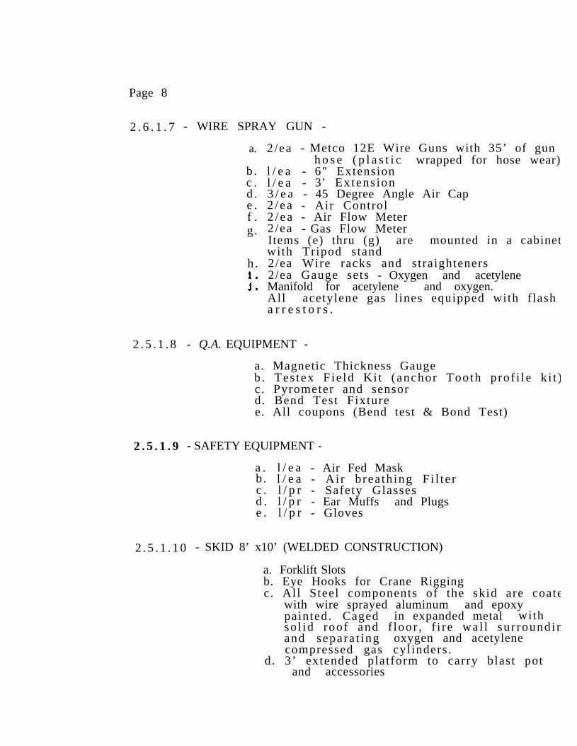
Page 8
2 . 6 . 1 . 7 - WIRE SPRAY GUN -
a.
b .c .d .e .f .g.
h .
2 /ea - Metco 12E Wire Guns with 35’ of gunh o s e ( p l a s t i c wrapped for hose wear)
l / e a - 6" Extensionl / e a - 3 ' Extens ion3 / e a - 45 Degree Angle Air Cap2 / e a - Air Control2 / e a - Air Flow Meter2 /ea - Gas Flow MeterItems (e) thru (g) are mounted in a cabinetwith Tripod stand2/ea Wire racks and straighteners2/ea Gauge sets - Oxygen and acetyleneManifold for acetylene and oxygen.All acetylene gas l ines equipped with f lasha r r e s t o r s .
2 . 5 . 1 . 8 - Q.A. EQUIPMENT -
a. Magnetic Thickness Gaugeb . Tes tex F ie ld Ki t (anchor Tooth prof i le k i t )c. Pyrometer and sensord. Bend Test Fixturee. All coupons (Bend test & Bond Test)
2 . 5 . 1 . 9 - SAFETY EQUIPMENT -
a . l / e a - Air Fed Maskb . l / e a - Ai r b rea th ing F i l te rc . l / p r - Safety Glassesd . l / p r - Ear Muffs and Plugse . l / p r - Gloves
2 . 5 . 1 . 1 0 - SKID 8’ x10’ (WELDED CONSTRUCTION)
a. Forklift Slotsb. Eye Hooks for Crane Riggingc. All Steel components of the skid are coate
with wire sprayed aluminum and epoxypainted. Caged in expanded metal withso l id roof and f loor , f i re wal l sur roundinand separa t ing oxygen and acetylenecompressed gas cylinders.
d. 3’ extended platform to carry blast pot and accessories
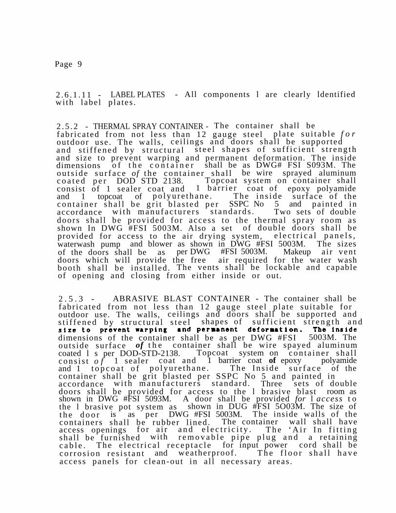
Page 9
2 . 6 . 1 . 1 1 - LABEL PLATES - All components l are clearly ldentifiedwi th labe l p la tes .
2 . 5 . 2 - THERMAL SPRAY CONTAINER - The container shall befabr ica ted f rom not l ess than 12 gauge s tee l p l a t e s u i t a b l e f o routdoor use . The wal l s , ce i l ings and doors sha l l be suppor teda n d s t i f f e n e d b y s t r u c t u r a l s t e e l s h a p e s o f s u f f i c i e n t s t r e n g t hand size to prevent warping and permanent deformation. The insidedimensions o f t h e c o n t a i n e r shall be as DWG# FSI S093M. Theo u t s i d e s u r f a c e of t h e c o n t a i n e r s h a l l be wire sprayed aluminumc o a t e d p e r DOD STD 2138. Topcoat system on container shallconsist of 1 sealer coat and 1 b a r r i e r coat of epoxy polyamideand 1 topcoat of p o l y u r e t h a n e . T h e i n s i d e sur face of thec o n t a i n e r s h a l l b e g r i t b l a s t e d p e r SSPC No 5 and pain ted inaccordance w i t h m a n u f a c t u r e r s s t a n d a r d s . Two sets of doubledoors sha l l be provided for access to the thermal spray room asshown In DWG #FSI 5003M. Also a set of double doors sha l l beprovided for access to the air drying system, e l e c t r i c a l p a n e l s ,waterwash pump and blower as shown in DWG #FSI 5003M. The sizesof the doors shall be as per DWG #FSI 5003M. Makeup ai r ven tdoors which will provide the free air required for the water washbooth sha l l be ins ta l led . The vents shall be lockable and capableof opening and closing from either inside or out .
2 . 5 . 3 - ABRASIVE BLAST CONTAINER - The container shall befabr ica ted f rom not l ess than 12 gauge s tee l p la te su i tab le foroutdoor use. The walls, ceil ings and doors shall be supported ands t i f f e n e d b y s t r u c t u r a l s t e e l shapes of s u f f i c i e n t s t r e n g t h a n d
dimensions of the container shall be as per DWG #FSI 5003M. Theouts ide sur face of t h e container shall be wire spayed aluminumcoated l s per DOD-STD-2138. Topcoat system on c o n t a i n e r s h a l lc o n s i s t o f 1 sealer coat and 1 barrier coat of epoxy polyamideand 1 t o p c o a t o f p o l y u r e t h a n e . T h e I n s i d e s u r f a c e of thecontainer shall be gri t blasted per SSPC No 5 and painted inaccordance w i t h m a n u f a c t u r e r s s tandard . Three sets of doubledoors shall be provided for access to the l brasive blast room asshown in DWG #FSI 5093M. A door shall be provided for l access t othe l brasive pot system as shown in DUG #FSI 5O03M. The size oft h e d o o r is as per DWG #FSI 5003M. The inside walls of theconta iners sha l l be rubber l ined . The container wall shall haveaccess openings f o r a i r a n d e l e c t r i c i t y . T h e ‘ A i r I n f i t t i n gsha l l be furn ished with r e m o v a b l e p i p e p l u g a n d a re ta in ingc a b l e . T h e e l e c t r i c a l r e c e p t a c l e for input power cord shall bec o r r o s i o n r e s i s t a n t and weatherproof . T h e f l o o r s h a l l h a v eaccess pane ls for c lean-out in a l l necessary a reas .

Page 10
2.5.4 - AIR DRYING SYSTEM - A twin tower regenerative air drye350 cfm l 190 psi with a mois ture t rap , o i l separa tor and au tomat ic dra ins sha l l be provided . This unit is mounted in a separatenclosure, which shall be Wire Sprayed Aluminum coated per D O DSTD-2138 and f in i shed pa in ted with the same paint system as thouts ide of the conta iners . The sys tem sha l l use ou ts idecompressed air supply (source of outside air may vary dependinupon the l o c a t i o n o f t h e c o n t a i n e r l z e d u n i t ) and deliver aih a v i n g q u a l i t y c o n f o r m i n g t o t h e r e q u i r e m e n t s of DOD-STD-2138for metal s p r a y p r o c e s s e s . The s ize of the regenera t ive a idryer enclosure shall be per DWG #FSI 5003M.
The Air Drying System consists of the fo l lowing components :
350 CFM Aftercooler350 CFM Regenerative Air Dryer350 CFM Coalescer Filter350 CFM Particulate Fil ter350 CFM Water trap - Automat ic Dra ins (mois ture separa tor )
2 .5 .6 - WATERWASH SPRAY BOOTH
2.5.5.1 FABRICATION AND CONSTRUCTION - The waterwash spray bootexhaust chamber s h a l l Comply with OSHA -1910.107 and sha lprovide complete vapor, fume and mist removal from the spraroom. Air ve loc i ty a t the f a c e o f t h e w a t e r curtain chambes h a l l b e not l e s s t h a n 2 0 0 f e e t p e r m i n u t e . The water wasc u r t a i n s h a l l b e r e c i r c u l a t i n g water type . The length of watec u r t a i n s h a l l be at l e a s t 7 feet with a collection pan or sumh o l d i n g s u f f i c i e n t w a t e r t o p r o v i d e s u c t i o n f o r t h e c i r c u l a t i npump. The water c u r t a i n s h a l l discharge 40 gallons per minutper foo t o f i t s l ength .
2 . 5 . 5 . 2 - ENCLOSURE - T h e s p r a y b o o t h e n c l o s u r e , water wasc u r t a i n , exhaust chamber, a n d c o l l e c t i n g p a n s h a l l b e c o n s t r u c tof 18 gauge (minimum) steel with baked enamel f in i sh . The spraybooth shall have inside dimensions as per DWG #FSI 5003M.
2 .5 .5 .3 - COVERED AREAS - T h e a r e a s a d j a c e n t to the water wascurtain and exhaust chamber shall be coved and covered to Isolatthe top and both sides preventing the accumulation of debris a nmeta l dus t res idue . The coving and covering material shall be othe same gauge and type l s the water wash curtain and the exhauschamber.

Page 11
2.5.5.4 - ACCESS - The cover ing pane ls sha l l be ins ta l led in sucha way so as to allow easy removal for access to the water washcurtain, exhaust chamber.
2 . 8 . 5 . 5 - WATER CIRCULATION SYSTEM - Water c i rcu la t ion sys temshall include frame mounted circulation pump with motor comply-ing wi th NFPA #70. Ci rcu la t ing pump d ischarge sha l l be 289gal lons per minute as requi red to main ta in the spec i f ied f low onthe water cur ta in .
2 .5 .5 .6 - EXHAUST FAN - Exhaust fan shall remove a minimum of11,900 SCFM air, at 3.4 inch water column in a 30 inch round ductor equivalent, complying with NFPA-91.
2 .5 .6 .7 - CONTROLS
2 . 5 . 5 . 7 . 1 - ENCLOSURES - E n c l o s u r e s for cont ro l pane ls andc o n t r o l s f o r t h e c i r c u l a t i n g p u m p and t h e e x h a u s t vent motorshall be enclosures approved as per OSHA 1910.70, and NEMA IC.
2 .5 .6 .7 .2 - START/STOP CONTROLS - Mot or c o n t r o l s s h a l l b ep r o v i d e d w i t h a “Power-On” indica t ing l igh t , and the pane lsshall be located 4 feet above t h e f l o o r . L a b e l t o i n d i c a t efunc t ion , use , and sequence of operation.
2 .6 .6 .8 - STACK - Booth sha l l have one s t ra igh t s tack te rmina t ingabove the roof. I t s h a l l b e f a b r i c a t e d from not less than 12gauge ga lvanized s tack mater ia l . A cap sha l l be inc luded wi ththe s tack .
2.6 - BLAST ROOM ENCLOSURE - T h e b l a s t r o o m s h a l l b e f a b r i c a t e df rom not l ess than 12 gauge s tee l p la te su i tab le for Ins ta l la t ioni n s i d e t h e c o n t a i n e r . A l l e r e c t i o n j o i n t s s h a l l b e s e a l e d t oform a dust and a i r t i g h t j o i n t . The walls, ceil ings and doorsshall be supported and s t i f f e n e d b y s t r u c t u r a l s t e e l shapes ofs u f f i c i e n t s t r e n g t h a n d s i z e to prevent warping or permanentdeformation. The enclosure shall be des igned to a l low en t ranceof adequate vent i la t ing a i r , whi le prevent ing the escape of dus to r o t h e r p o l l u t a n t s . The Inside working dimensions of the blastroom shall be as per DWG #FSI 6003M. Two sides of the blast roomshall be comprised of a set of double work doors, as shown onDWGS FSI 5003M.
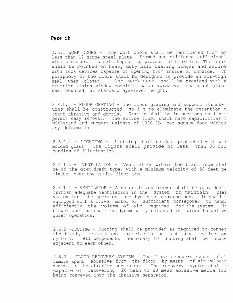
2.6.1 WORK DOORS - The work doors shall be fabricated from notless than 12 gauge steel plate, framed and stiffened sufficientlywith structural steel shapes to prevent distortion. The doorsshall be mounted on heavy duty ball bearing hinges and securedwith lock devices capable of opening from inside or outside. Thperiphery of the doors shall be designed to provide an sir-tighseal when closed. One work door shall be provided with aexterior vision window complete with abrasive resistant glassseal mounted, at standard eye-level height.
2.8.1.1 - FLOOR GRATING - The floor grating and support struct-ures shall be constructed so l s to eliminate the retention ospent abrasive and debris. Grating shall be in sections so l s tpermit easy removal. The entire floor shall have capabilities twithstand and support weights of 1000 lb. per square foot withouany deformation.
2.6.1.2 - LIGHTING - Lighting shall be dust protected with wirmolded glass. The lights shall provide no less than 80 foocandles of illumination.
2.6.1.3 - VENTILATION - Ventilation within the blast room shalbe of the down-draft type, with a minimum velocity of 50 feet peminute over the entire floor area.
2.6.1.4 - VENTILATOR - A motor driven blower shall be provided tfurnish adequate ventilation in the system to maintain cleavision for the operator and hygienic surroundings. It shall bequipped with a drive motor of sufficient horsepower to handlefficiently the volume of air required for the system. Thblower and fan shall be dynamically balanced in order to delivequiet operation.
2.6.2 -DUCTING - Ducting shall be provided as required to connecthe blast, reclamation, re-circulation and dust collectionsystems. All components necessary for ducting shall be locateadjacent to each other.
2.6.3 - FLOOR RECOVERY SYSTEM - The floor recovery system shalremove spent abrasive from the floor by means of air velocitducts, to the abrasive separator. The recovery system shall bcapable of recovering 20 mesh to 80 mesh abrasive media frobeing conveyed into the abrasive separator.

Page 13
2.6.4 - ABRASIVE RECOVERY, CONVEYING AND RECLAIMING SYSTEM -The unit shall incorporate an adequate system for recovery andconveying of spent abrasives from the blast room floor Into thereclaimer or cleaner. Upon entering the inlet of the reclaimer,abrasive and debris shall be separated from the conveying airstream in a cyclone chamber from which the air stream willcontinue on to the main dust collector. The clean abrasive shallthen pass on to the blast generator for reuse.
2.6.4.1 - DUST COLLECTOR - A dry type collector shall be provid-ed. The dust collector shall be completely compatible for usewith the abrasive blast room furnished under this specification.The collector shall house a series of cloth composition bagsproviding a 3.5 to 1 air to cloth ratio. The dust collectorfurnished shall be designed for exterior installation andoperation.
The bags shall be independently suspended from a sturdy framelocated at the top of the unit. The bags shall also be independ-ently replaceable. An automatically operated mechanism shall beprovided to periodically shake the bags, releasing theaccumulated dust into the hopper and into the 55 gallon disposaldrums located in the extreme bottom of the hopper.
Provisions shall be provided to assure easy access to the bagarea for inspection and replacement of the filter bags asnecessary, as well as the performance of other types of unitmaintenance.
2.7.5 - BLAST GENERATOR - The blast machine shall consist of 2pressure blast pots each having a 690 lb. capacity. Intermittentaction pressure type generator, with an adjustable pressurerange shall be furnished. It shall be rigidly constructed inaccordance with ASME specifications for unfired vessels withworking pressure up to 100 psig. The generator shall be of theproper design (size and capacity ) to utilize coarse abrasivesand obtain desired performance results per DOD-STD-2138. Thegenerator shall have an efficient transfer or refilling mechan-ism, actuated by the operator at the blasting nozzle. The blastgenerator furnished shall be designed to supply an adequateamount of abrasive to sustain one operator using a 5/16” nozzleas required to obtain satisfactory blasting results. A pressuregage shall be installed on the generator. Abrasive delivery fromthe generator chamber to the blast hose shall be controlled byadjustable operated abrasive feed valves. The valves shall be
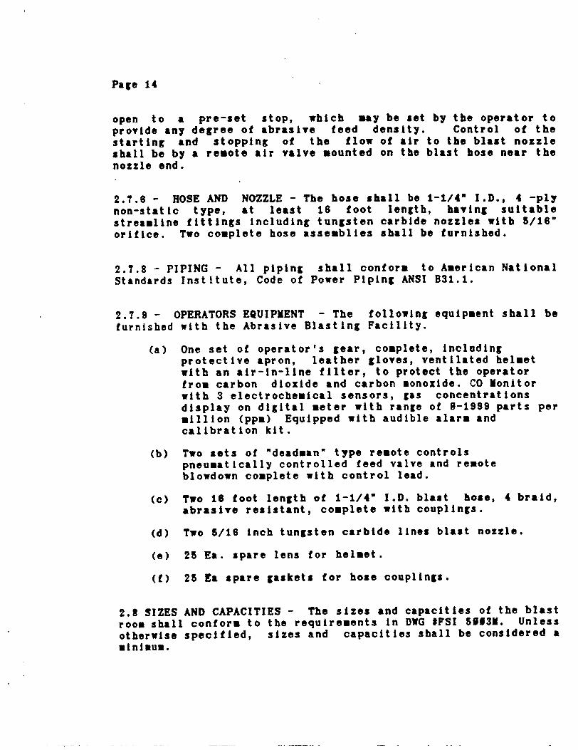

Page 16
2.9 ADDITIONAL EQUIPMENT
2.9.1 -RAMP- A fabricated 1/4” steel platform shall be fastenedin between the blast and spray container. The platform will be 8foot wide by 12 foot long and level with the spray room floor.The entire platform shall be WSA coated and furnished paintedwith the same paint system as the outside of the containers.
2.9.2 ROOF - A corrugated metal roof mounted on a steel angleiron frame which is attached to both the spray and blast contain-ers shall be provided. The frame work shall be WSA coated andfinished painted. The metal corrugated roof panels areoverlapped and attached to the frame and sealed with siliconcaulking. The roof frame is centered on the blast and spraybooth doors. The overall dimensions are 14’ wide x 40’ long.Where the roof extends beyond the containers an angled bracket ismounted for support.
2.9.3 - OVERHEAD TROLLEY SYSTEM - A 6'' I Beam 40’ long isl attached to the inside roof of the blast and spray containers andextends out each side 6’ and spans the 12’ in between the units.Two 1-1/2 ton capacity pneumatic hoists with manual trolleys aremounted on the I beam. The overhead trolley system will becertified for a 2000 lb. capacity.
2.9.4 -TURNTABLES - 2 Ea manual rotating round tables shall befurnished. The tables are 40” dia. and 12” high. They havehandles for rotation and lifting.
2.9.6 TABLES - A spray table 36” X 36” is fabricated andattached to the front 0f the spray booth. It is hinged and canbe collapsed laying in front of the spray booth.
A work table 16” x 38” is fabricated and attached underneath thespray console. It is hinged and collaspable.
2.9.6 BOTTLE RACK - 1 Ea 8 cylinder acetylene bottle storagerack is fabricated and furnished. The bottle rack has fork liftopening and lifting eyes for use with a crane. The cylinders arechained in place in accordance with Standard Safety Practices forcylinder handling.


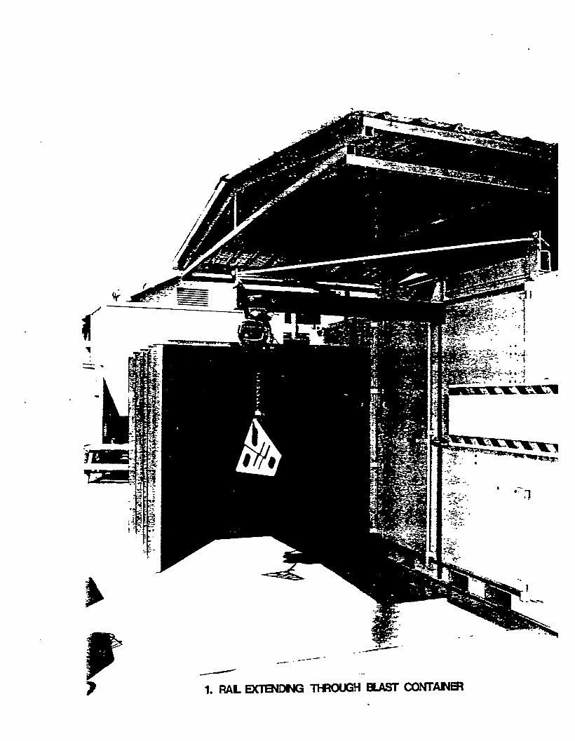


CORROSION CONTROL SHOP
Many of the consumable
CONSUMABLES
items are used in both thermal spray andpaint facilities. The following list is a combination of theseitems and utilizes the following legend. (P) = Paint Facility,(TS) = Thermal Spray Facility, and (B) = Both Paint and ThermalSpray Facilities.
APPROX.ITEM QUANTITY COST------------------------ ------------------------ -----------------
1.
2.
3.
4.
5.
6.
7.
8.
9.
10•
11.
12.
13.
14.
Ear Plugs (B)
Air-Fed Hood (B)(disposable)
Bracket Face Shield (B)(disposable)
Cotton Gloves (B)
Silver Duct Tape (B)
Rigid Plastic Disk (B)(capping off valves)
press-O-Film (B)
Rubber Gloves (B)(lightweight)
Cotton Rags (B)(wiping)
oxygen (TS)
Acetylene (TS)
Formula 150 (B)(EPOXY Primer, green)
Formula 151 (p)(EPOXY coating kit,haze gray semi-gloss,topcoat)
TT-E-490 Enamel (P)(haze gray)
1 Bx (200 pair)
1 Ea
1 E a
1 Pair
1 Roll
1 Ea
1 Roll
1 Pair
1 Bundle
Cubic Ft.
Cubic Ft.
5 Gal.(2 parts/kit)
5 Gal.(2 parts/kit)
5 Gal.
10.16
10.75
6.07
1.89
3.50
.30
29.00
.81
26.09
. 0 4
. 0 9
1 2 7 . 8 1
2 1 1 . 6 8
6 2 . 8 7
6 8 .
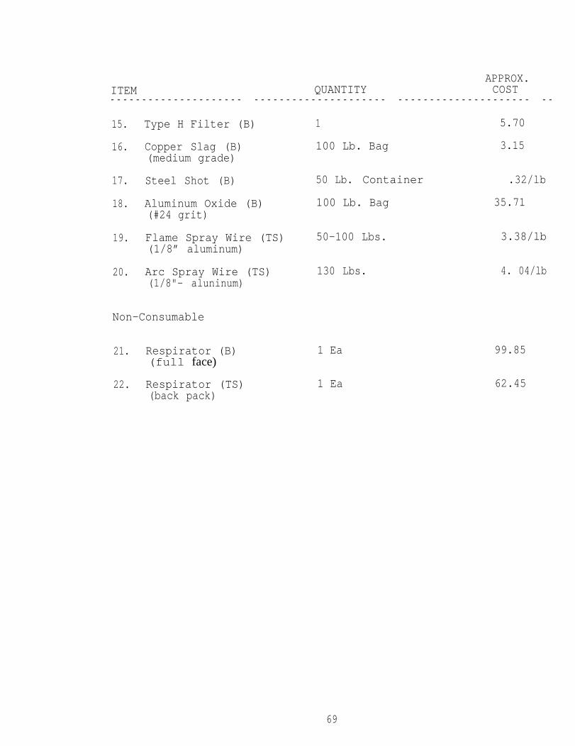
APPROX.ITEM QUANTITY COST- - - - - - - - - - - - - - - - - - - - - - - - - - - - - - - - - - - - - - - - - - - - - - - - - - - - - - - - - - - - - - - - -
15.
16.
17.
18.
19.
20.
Type H Filter (B) 1 5.70
Copper Slag (B) 100 Lb. Bag 3.15(medium grade)
Steel Shot (B) 50 Lb. Container .32/lb
Aluminum Oxide (B) 100 Lb. Bag 35.71(#24 grit)
Flame Spray Wire (TS) 50-100 Lbs.(1/8” aluminum)
3.38/lb
Arc Spray Wire (TS) 130 Lbs. 4. 04/lb(1/8"- aluninum)
Non-Consumable
21. Respirator (B)(full face)
22. Respirator (TS)(back pack)
1 Ea
1 Ea
69
99.85
62.45

WIRE SPRAYED ALUMINUM AND PAINT
LIFE EXPECTANCY &
LIFE CYCLE COST COMPARISONS
7 0

LIFE EXPECTANCY
Thermal Sprayed Coatings
The results of a 19 year study by the American Welding Society ofthe corrosion protection afforded by wire-flame sprayed aluminumapplied to low carbon steel showed that aluminum sprayed coatings0.003 to 0.006 inches thick, both sealed and unsealed, gavecomplete base metal protection from corrosion in sea water andalso in severe marine and industrial atmospheres.
The sealing system for aluminum primarily enhanced appearance andshowed no base metal rust after 19 years.
Where aluminum coatings showed damage such as chips and scrapes,corrosion did not progress, suggesting the occurrence of galvanicprotection.
Inorganic Zinc Coatings
The six “Universe” class tankers, 320,000 tons each, are a goodexample of ships protected both on the interior and exterior withinorganic zinc. These ships were first coated with an inorganiczinc preconstruction primer and in the most critical areas withan additional full coat of inorganic zinc. The total footagecoated was over 18 million square feet or 1,700,000 square miles.After five to seven years of service, no corrosion was evidentand no maintenance was required on the exteriors except atseverely abraded areas. Even after 12 to 14 years service, theexterior surfaces are thought to be well protected on theremaining ships.
71
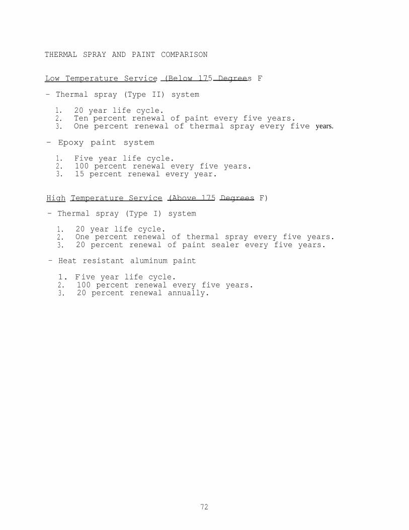
THERMAL SPRAY AND PAINT COMPARISON
Low Temperature Service (Below 175 Degrees F
- Thermal spray (Type II) system
1. 20 year life cycle.2. Ten percent renewal of paint every five years.3. One percent renewal of thermal spray every five years.
- Epoxy paint system
1. Five year life cycle.2. 100 percent renewal every five years.3. 15 percent renewal every year.
High Temperature Service (Above 175 Degrees F)
- Thermal spray (Type I) system
1. 20 year life cycle.2. One percent renewal of thermal spray every five years.3. 20 percent renewal of paint sealer every five years.
- Heat resistant aluminum paint
1. Five year life cycle.2. 100 percent renewal every five years.3. 20 percent renewal annually.
72

LIFE
USS
CYCLE COST ANALYSIS
STANDLEY (CG-32) (USS STANDLEY Report
571 steam valves were thermal sprayed.
Cost savings after 5-year evaluation:
cost
cost
USS
of Painting -
571 valves x $45 x 8 cycles =
of Thermal Spraying -
571 valves x $90 (2 mhrs ea.)
COST SAVINGS TO NAVYUSING WSA COATINGS
CONSTELLATION
#TM-28-83-178)
$ 205,560.00
$ 51,390.00- - - - - - - - - - - -
$ 154,170.00
Life cycle of thermal spray coating is 20 years with 10% repairevery five years.
Catwalks receive painting every 2-1/2 years.
Catwalks are replaced every 5 years.
Production man hour rate is $45 per hour.
2,096 square feet.
73

JOB COST/FREQUENCY 20 YR. COST------ ------ ------------------------ ------ ------ -----------------Cost of Painting
Cost of Replacement(Painting not incl.)
TOTAL
Cost of Thermal Spray
Repair Costs
TOTAL
NET SAVINGS
607 mhrs x 9 cycles x $45 $ 245,835
6,885 mhrs x 4 cycles x $45 $ 1,239,300---------
$ 1,485,135
2,882 mhrs x 1 cycle x $45 $ 129,690
288.2 mhrs x 4 cycles x $45 $ 51,876-------
$ 181,566
$ 1,485,135- $ 181,566
---------
$ 1,303,569
- Cost of thermal spray includes preparation, sealing, andpainting.
74

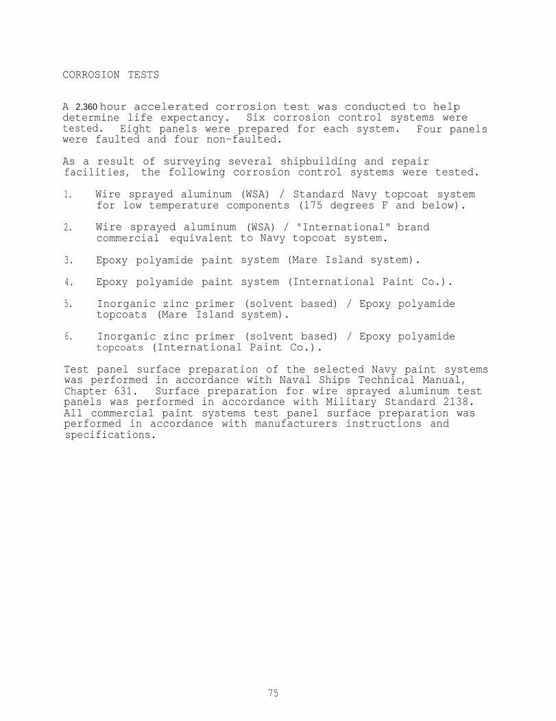
CORROSION TESTS
A 2,360 hour accelerated corrosion test was conducted to helpdetermine life expectancy. Six corrosion control systems weretested. Eight panels were prepared for each system. Four panelswere faulted and four non-faulted.
As a result of surveying several shipbuilding and repairfacilities, the following corrosion control systems were tested.
1. Wire sprayed aluminum (WSA) / Standard Navy topcoat systemfor low temperature components (175 degrees F and below).
2. Wire sprayed aluminumcommercial equivalent
3. Epoxy polyamide paint
4. Epoxy polyamide paint
5. Inorganic zinc primertopcoats (Mare Island
6. Inorganic zinc primer
(WSA) / "International" brandto Navy topcoat system.
system (Mare Island system).
system (International Paint Co.).
(solvent based) / Epoxy polyamidesystem).
(solvent based) / Epoxy polyamidetopcoats (International Paint Co.).
Test panel surface preparation of the selected Navy paint systemswas performed in accordance with Naval Ships Technical Manual,Chapter 631. Surface preparation for wire sprayed aluminum testpanels was performed in accordance with Military Standard 2138.All commercial paint systems test panel surface preparation wasperformed in accordance with manufacturers instructions andspecifications.
75

Coating System #1: WIRE SPRAYED ALUMINUM AND STANDARD MAREISLAND COATING SYSTEM FOR LOW TEMPERATURECOMPONENTS
Test panel Material: Carbon Steel Size: 3"1 X 4" X 3/16"Procedure (WSA): Process Instruction 705procedure (paint) : NAVSEA S9086-VD-STM-OO0, Chapter 631
< Test Panel parameters >
Panel Numbers: 1 - 8
Faulted 1 - 4 Non-faulted 5 - 8
Date: 11-28-69
I. ANCHOR TOOTH BLASTING (SP-5 WHITE METAL BLAST)
A. Grit Type: Aluminum oxide
B. Grit Size: # 2 4
C. Profile: 4.5
II. COATINGS
A. Wire Spray Parameters
1.
2.
3.
4.
5.
6.
7.
8.
a
10.
11.
12 l
Time between blasting and spraying:(less than 4 hours)
Wire type: 99.5% pure aluminum
Wire size: 1/8"
Gun type: METCO 1O-E
Atomizing air pressure: 47 PSI
Nozzle size: 1/8"
Fuel gas: Acetylene
Fuel gas regulator:
Air regulator (PSI):
Fuel gas flow meter (CFH) : 40
Oxygen flow meter (CFH): 43
Air flow meter (CFH): 53
2 hours
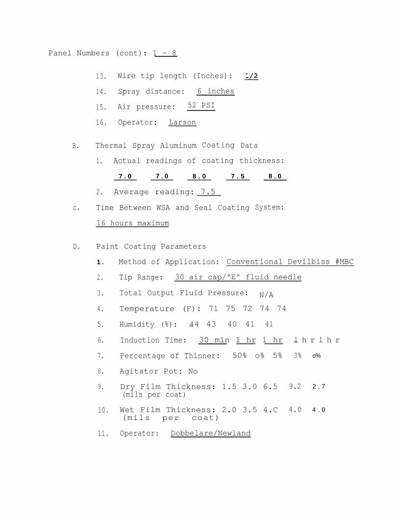
Panel Numbers (cont): 1 - 8
B.
c.
D.
13. Wire tip length (Inches):
14. Spray distance: 6 inches
15. Air pressure: 52 PSI
16. Operator: Larson
Thermal Spray Aluminum
1. Actual readings of
Coating Data
coating thickness:
7 . 0 7 . 0 8 . 0 7 . 5
2. Average reading: 7.5
Time Between WSA and Seal Coating
16 hours maximum
Paint Coating Parameters
1 .
2.
3.
4.
5.
6.
7.
8.
9.
10.
11.
8 . 0
System:
Method of Application: Conventional Devilbiss #MBC
Tip Range: 30 air cap/"E" fluid needle
Total Output Fluid Pressure: N/A
Temperature (F): 71 75 72 74 74
Humidity (%): 44 43 40 41 41—
Induction Time: 30 min 1 hr 1 hr
Percentage of Thinner: 50% o% 5%
Agitator Pot: No
l h r l h r—
3%
Dry Film Thickness: 1.5 3.0 6.5 9.2(mils per coat)
Wet Film Thickness: 2.0 3.5 4.C 4.0(mils per coat)
Operator: Dobbelare/Newland
o%
2 . 7
4 . 0
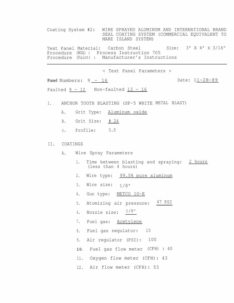
Coating System #2: WIRE SPRAYED ALUMINUM AND INTERNATIONAL BRAND
Test PanelProcedureProcedure
SEAL COATING SYSTEM (COMMERCIAL EQUIVALENT TOMARE ISLAND SYSTEM)
Material: Carbon Steel Size: 3" X 4" X 3/16"(WSA) : Process Instruction 705(Paint) : Manufacturer’s Instructions
< Test Panel Parameters >
Panel Numbers: 9 - 16
Faulted 9 - 12 Non-faulted 13 - 16
I. ANCHOR TOOTH BLASTING (SP-5 WHITE
A. Grit Type: Aluminum oxide
B. Grit Size: # 24
c. Profile: 3.5
II. COATINGS
A. Wire Spray Parameters
Date: 11-28-89
METAL BLAST)
1.
2.
3.
4.
5.
6.
7.
8.
9.
Time between blasting and spraying: 2 hours(less than 4 hours)
Wire type: 99.5% pure aluminum
Wire size: 1/8"
Gun type: METCO 1O-E
Atomizing air pressure: 47 PSI
Nozzle size: 1/8"
Fuel gas: Acetylene
Fuel gas negulator:
Air regulator (PSI):
1 0 . Fuel gas flow meter
15
100
(CFH) : 40
11. Oxygen flow meter (CFH): 43
12. Air flow meter (CFH): 53

Panel Numbers (cent): 9 - 16
B.
c.
D.
13. Wire tip length (Inches): 1/2
14. Spray distance: 6 inches
15. Air pressure: 52 PSI
16. operator: Larson
Thermal Spray Aluminum
1. Actual readings of
9.0 10.0
2. Average reading:
Time Between WSA and
16 hours maximum
Coating Data
coating thickness:
11.0 10.0 10.0
10.0
Seal Coating System:
Paint Coating Parameters
1.
2.
3.
4.
5.
6.
7.
8.
9.
10.
11.
Method of Application: Brush
Tip Range: N/A
Total Output Fluid Pressure: N/A
Temperature (F): 75 71
Humidity (%) : 44 50
Induction Time: 30 min
Percentage of Thinner: O% O%
Agitator Pot: No
Dry Film Thickness: 3.5 8.2 25.0(mils per coat)
Wet Film Thickness: 4.0(roils per coat)
Operator: Dobbelare/Newland
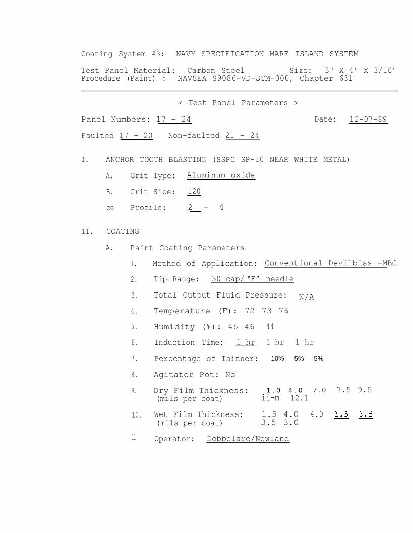
Coating System #3: NAVY SPECIFICATION MARE ISLAND SYSTEM
Test Panel Material: Carbon Steel Size: 3" X 4" X 3/16"Procedure (Paint) : NAVSEA S9086-VD-STM-000, Chapter 631
< Test Panel Parameters >
Panel Numbers: 17 - 24 Date: 12-07-89
Faulted 17 - 20 Non-faulted 21 - 24
I. ANCHOR TOOTH BLASTING (SSPC SP-10 NEAR WHITE METAL)
A. Grit Type: Aluminum oxide
B. Grit Size: 120
co Profile: 2 - 4
11. COATING
A. Paint Coating Parameters
1.
2.
3.
4.
5.
6.
7.
8.
9.
10.
11.-
Method of Application: Conventional Devilbiss +MBC
Tip Range: 30 cap/ “E” needle
Total Output Fluid Pressure: N/A
Temperature (F): 72 73 76
Humidity (%): 46 46
Induction Time: 1 hr
Percentage of Thinner:
Agitator Pot: No
Dry Film Thickness:(mils per coat)
44
1 hr 1 hr
10% 5% 5%
1 . 0 4 . 0 7 . 0ii-m 12.1
Wet Film Thickness: 1.5 4.0 4.0(mils per coat) 3.5 3.0
Operator: Dobbelare/Newland
7.5 9.5

Coating System #4: "INTERNATIONAL" BRAND EQUIVALENT TO MAREISLAND SYSTEM
Test Panel Material: Carbon Steel Size: 3" x 4" x 3/16"procedure (paint) : Manufacturer’s Instructions
Date: 12-07-89
< Test Panel Parameters >
Panel Numbers: 25 - 32
Faulted 25 - 28 Non-faulted 29 - 32
I. ANCHOR TOOTH BLASTING (SSPC SP-10 NEAR WHITE METAL)
A. Grit Type: Aluminum oxide
B. Grit Size: 120
c. Profile: 2-4
II. COATING
A. Paint Coating Parameters
1.
2.
3.
4.
5.
6.
7.
8.
9.
1 0 .
1 1 .
Method of Application: Brush/Spray
Tip Range: Brush/30 cap/ "E" needle
Total Output Fluid Pressure: N/A
Temperature (F): 75
Humidity (%): 42
induction Time: 1 hr
Percentage of Thinner: O%
Agitator Pot: No
Dry Film Thickness: 2.0 4.0 6.2 8.4(mils per coat)
Wet Film Thickness: 3.0 3.5 2.5 4.0(mils per coat)
Operator: Dobbelare/Newland
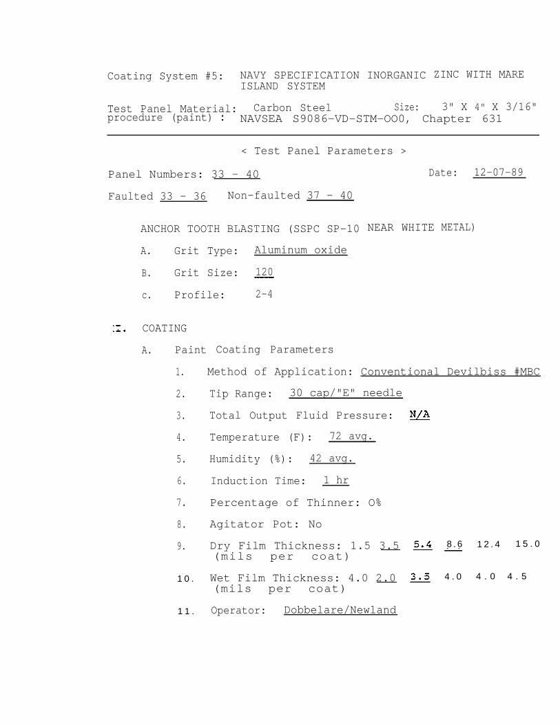
Coating System #5: NAVY SPECIFICATION INORGANICISLAND SYSTEM
Test Panel Material: Carbon Steel Size:
ZINC WITH MARE
3" X 4" X 3/16"procedure (paint) : NAVSEA S9086-VD-STM-OO0, Chapter 631
< Test Panel Parameters >
Panel Numbers: 33 - 40
Faulted 33 - 36 Non-faulted 37 - 40
ANCHOR TOOTH BLASTING (SSPC SP-10
A. Grit Type: Aluminum oxide
B. Grit Size: 120
c. Profile: 2-4
COATING
A. Paint
1.
2.
3.
4.
5.
6.
7.
8.
9.
1 0 .
1 1 .
Coating Parameters
Date: 12-07-89
NEAR WHITE METAL)
Method of Application: Conventional Devilbiss #MBC
Tip Range: 30 cap/"E" needle
Total Output Fluid Pressure:
Temperature (F): 72 avg.
Humidity (%): 42 avg.
Induction Time: 1 hr
Percentage of Thinner: O%
Agitator Pot: No
Dry Film Thickness: 1.5 3.5(mils per coat)
Wet Film Thickness: 4.0 2.0(mils per coat)
Operator: Dobbelare/Newland
8 . 6
4 . 0
1 2 . 4 1 5 . 0
4 . 0 4 . 5
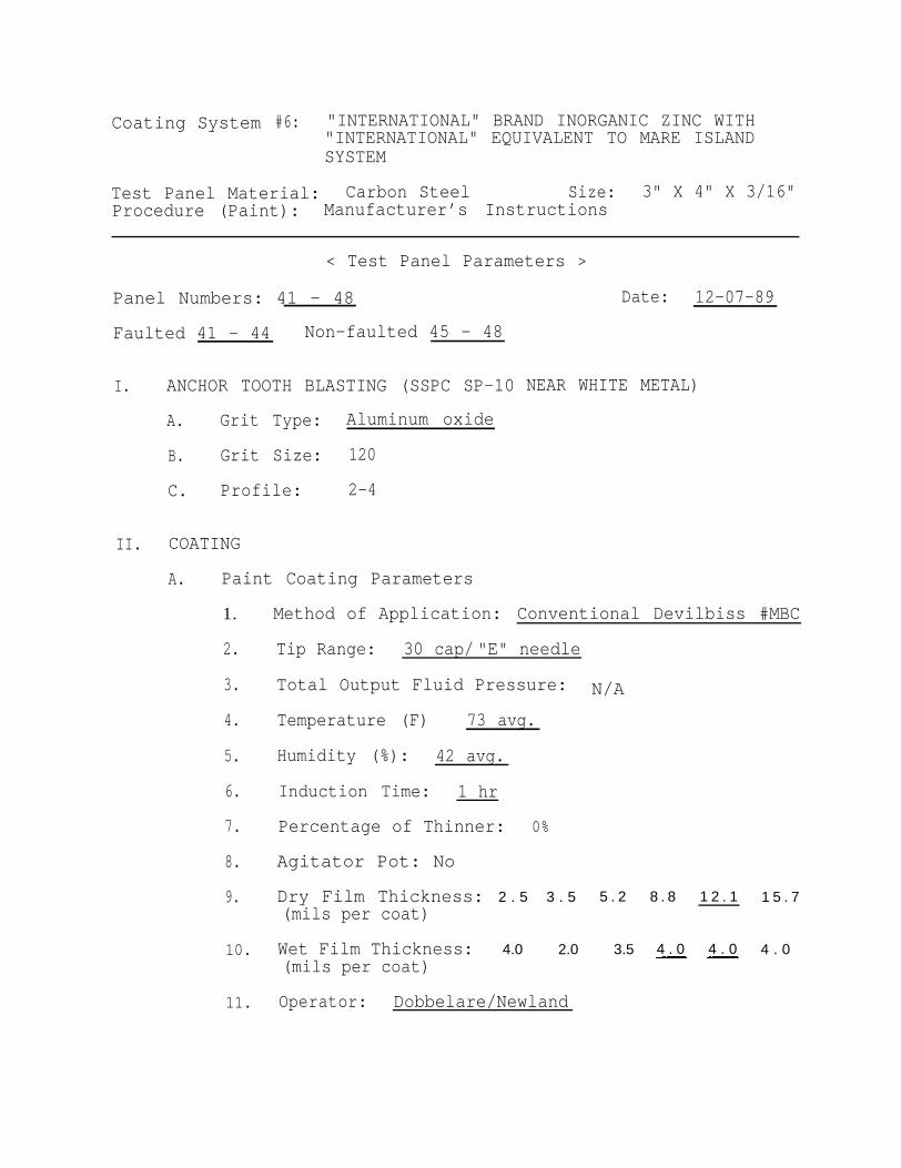
Coating System #6: "INTERNATIONAL" BRAND INORGANIC ZINC WITH"INTERNATIONAL" EQUIVALENT TO MARE ISLANDSYSTEM
Test Panel Material: Carbon Steel Size: 3" X 4" X 3/16"Procedure (Paint): Manufacturer’s Instructions
< Test Panel Parameters >
Panel Numbers: 41 - 48
Faulted 41 - 44 Non-faulted 45 - 48
I. ANCHOR TOOTH BLASTING (SSPC SP-10
A. Grit Type: Aluminum oxide
B. Grit Size: 120
C. Profile: 2-4
II. COATING
A. Paint Coating Parameters
1.
2.
3.
4.
5.
6.
7.
8.
9.
10.
11.
Date: 12-07-89
NEAR WHITE METAL)
Method of Application: Conventional Devilbiss #MBC
Tip Range: 30 cap/ "E" needle
Total Output Fluid Pressure: N/A
Temperature (F)
Humidity (%):
73 avg.
42 avg.
Induction Time: 1 hr
Percentage of Thinner:
Agitator Pot: No
Dry Film Thickness:(mils per coat)
Wet Film Thickness:(mils per coat)
0%
2 . 5 3 . 5 5 . 2
4.0 2.0 3.5
Operator: Dobbelare/Newland
8 . 8
4 . 0
1 2 . 1
4 . 0
1 5 . 7
4 . 0

PUGET SOUND NAVAL SHIPYARDQUALITY ASSURANCE OFFICE
Laboratory Division
Code 134.6 MFA:lms
Metallurgy Branch Report No. 9OPS06804A
Subj: EVALUATION OF SIX CORROSION RESISTANT SYSTEMS AFTER 2360 HOURSALT FOG TEST
Ref: (a) ASTM B117-74(b) ASTM D714-87
1. Experimental Procedure
Six corrosion resistant systems were tested in accordance withreference (a). There was a total of eight panels for each system, fourfaulted and four nonfaulted. The test ran for 2000 hours; the samples wereremoved for evaluation; and the test continued for another 360 hours. The six [Rev.systems are described below.
Wire sprayed aluminum and Navy specification seal coatingsystem(per #2138). The surface preparation was SP-5, white metal blast.Test panels 1 through 8.
System 2: Wire sprayed aluminum(International brand paint).
and commercial seal coat systemThe surface preparation was SP-5, white metal
blast. Test panels 9 through 16.
System 3: Navy specification: Hare Island series (epoxy polyamide) sealcoating system (per 1631). The surface preparation was SP-10, near-whitemetal blast. Test panels 17 through 24.
System 4: Commercial equivalent to Navy specification Mare Island system(International brand paint coating system, 'FP series"). The surfacepreparation was SP-10, near-white metal blast. Test panels 25 through 32.
System 5: Navy specification "Inorganic zinc," Mare Island system. Thesurface preparation was SP-10, near-white metal blast. Test panels 33through 40.
near-white metal blast.
: Inorganic zinc with 'FP* seriespreparation was SP-10,
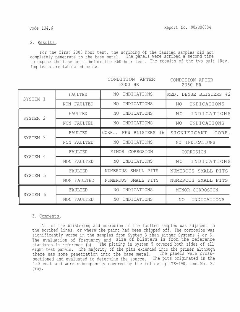
Code 134.6 Report No. 90PS06804
2. Results.
For the first 2000 hour test, the scribing of the faulted samples did notcompletely penetrate to the base metal. The panels were scribed a second timeto expose the base metal before the 360 hour test. The results of the two salt [Rev.fog tests are tabulated below.
CONDITION AFTER CONDITION AFTER2000 HR 2360 HR
FAULTED NO INDICATIONS MED. DENSE BLISTERS #2SYSTEM 1
NON FAULTED NO INDICATIONS NO INDICATIONS
FAULTED NO INDICATIONS NO INDICATIONSSYSTEM 2
NON FAULTED NO INDICATIONS NO INDICATIONS
FAULTED CORR., FEW BLISTERS #6 SIGNIFICANT CORR.SYSTEM 3
NON FAULTED NO INDICATIONS NO INDICATIONS
FAULTED MINOR CORROSION CORROSIONSYSTEM 4
NON FAULTED NO INDICATIONS NO INDICATIONS
FAULTED NUMEROUS SMALL PITS NUMEROUS SMALL PITS SYSTEM 5
NON FAULTED NUMEROUS SMALL PITS NUMEROUS SMALL PITS
FAULTED NO INDICATIONS MINOR CORROSIONSYSTEM 6
NON FAULTED NO INDICATIONS NO INDICATIONS
3. Comments.
All of the blistering and corrosion in the faulted samples was adjacent tothe scribed lines, or where the paint had been chipped off. The corrosion wassignificantly worse in the samples from System 3 than either Systems 4 or 6.The evaluation of frequency and size of blisters is from the referencestandards in reference (b). The pitting in System 5 covered both sides of alleight test panels. The majority of the pits extended into the primer althoughthere was some penetration into the base metal. The panels were cross-sectioned and evaluated to determine the source. The pits originated in the150 coat and were subsequently covered by the following lTE-490, and No. 27gray.

Code 134.6 Report NO. 90PS06804
The wire sprayed aluminum/commercial seal coat system used in System 2provided better protection from the salt fog environment than any of the otherfive systems. The results from the 360 hour test should be representative ofthe indications found in the six systems. If the test panels had been scribedto the base metal for the first 2000have been more severe.
5. Revision-A is issued to correcthours of testing performed.
hours, the corrosion and blistering would
an incorrect reference to the number of
Distribution:Shop 26


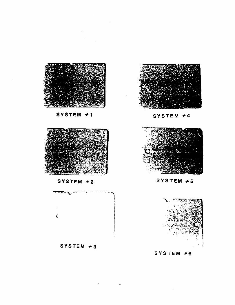


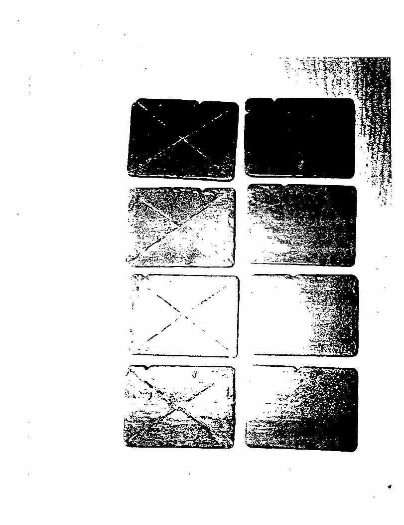


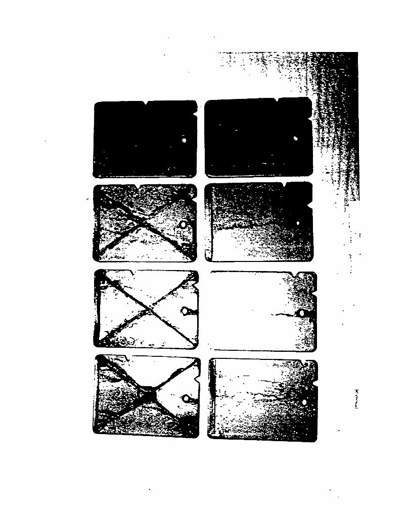

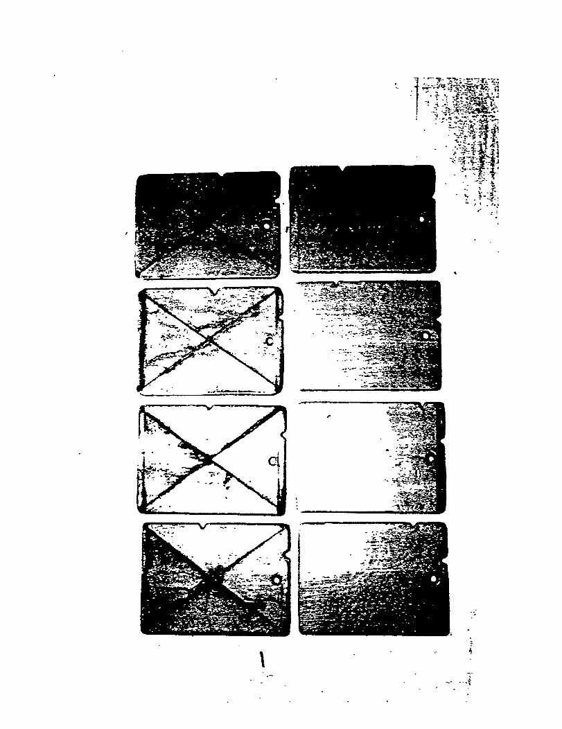

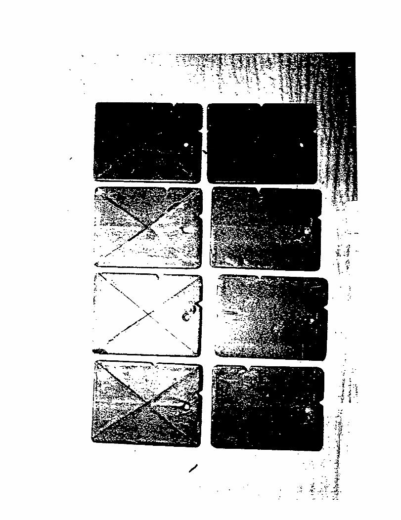


WIRE SPRAYED ALUMINUM
RECOMMENDED AREAS &
HISTORICAL PHOTOGRAPHS
76

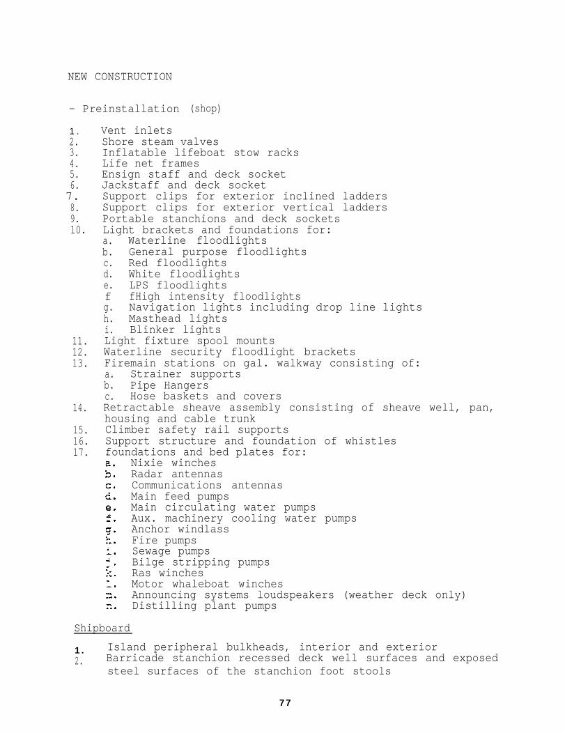
NEW CONSTRUCTION
- Preinstallation
1 .2.3.4.5.6.
7.8.9.10.
11.12.13.
14.
15.16.17.
(shop)
Vent inletsShore steam valvesInflatable lifeboat stow racksLife net framesEnsign staff and deck socketJackstaff and deck socketSupport clips for exterior inclined laddersSupport clips for exterior vertical laddersPortable stanchions and deck socketsLight brackets and foundations for:a. Waterline floodlightsb. General purpose floodlightsc. Red floodlightsd. White floodlightse. LPS floodlightsf fHigh intensity floodlightsg. Navigation lights including drop line lightsh. Masthead lightsi. Blinker lightsLight fixture spool mountsWaterline security floodlight bracketsFiremain stations on gal. walkway consisting of:a. Strainer supportsb. Pipe Hangersc. Hose baskets and coversRetractable sheave assembly consisting of sheave well, pan,housing and cable trunkClimber safety rail supportsSupport structure and foundation of whistlesfoundations and bed plates for:.
Nixie winchesRadar antennasCommunications antennasMain feed pumpsMain circulating water pumpsAux. machinery cooling water pumpsAnchor windlassFire pumpsSewage pumpsBilge stripping pumpsRas winchesMotor whaleboat winchesAnnouncing systems loudspeakers (weather deck only)Distilling plant pumps
Shipboard
1 . Island peripheral bulkheads, interior and exterior2. Barricade stanchion recessed deck well surfaces and exposed
steel surfaces of the stanchion foot stools
7 7

REPAIR AREAS FOR THERMAL SPRAY
Shipboard
Sanitary spaces
Bulkheads
Weather decks
Pump room floors
Tie downs
Deck lights
Catwalk stanchions
Fire stations
Deck wells
Rule of Thumb: If you can’t sandblast in a space on boardship, then you can’t thermal spray in that space.
Shop
Hundreds of components have beenNaval Shipyard. Eighty-five to 90interchangeable items with privateexamples of some of the components
Bench supportsFire pump foundationsLadder treadsFire pump bed platesstrainersGas cylinder containersStaging platformsRight-hand track sectionLeft-hand track sectionAccess cover assemblySafety net framesTrack coverHinge protectorssmoke stackHydraulic cylinderSewer pumpTransition spoolsBase platesFoundation legsHP drain pipe
thermal sprayed at Puget Soundpercent of these items areindustry. Following arethermal sprayed in-shop.
Deck gratingsMuffler chamberTrench coversSluice gate coverDuCt coversReduction gearBracketsPipe flangeManifoldsHand railsShore hatchesRacksLight bracketsDrain trough coversFire main pumpDischarge spoolGuard shanksAntenna standsWater troughClamps
78

LaddersPiping lengthsScupper ringsBlast padsBooster pump foundationsSafety netsFlangesOutlet boxFire pump housingstop logImpellerPump well coversDry dock sewer connectionPistons DoorsMuffler extensionPipe hangersStanchionsStairsCapstan foundationSeal ringSliding foot assembly
Valves and valve bodies - Numerous
Sizes range from 1/4" globe valves
Winch foundationsBarricade stanchionsFitting panel liftManway coverCondenserTow plateWhistle, steam pump foundationAir elbowHoldback troughArresting gear component2" "y"patternStrut armsEye assemblyExhaust “Y”Hinge leafHot water heater enclosureTrip throttleTrunkPump sub-baseCrank armHinge bearingsPlatforms
types:
to 48”
GlobeGateReliefNeedleCombinationSteamLift CheckBlowoffExhaust, etc.
flapper check valves.
79

HISTORICAL PHOTOGRAPHS
80

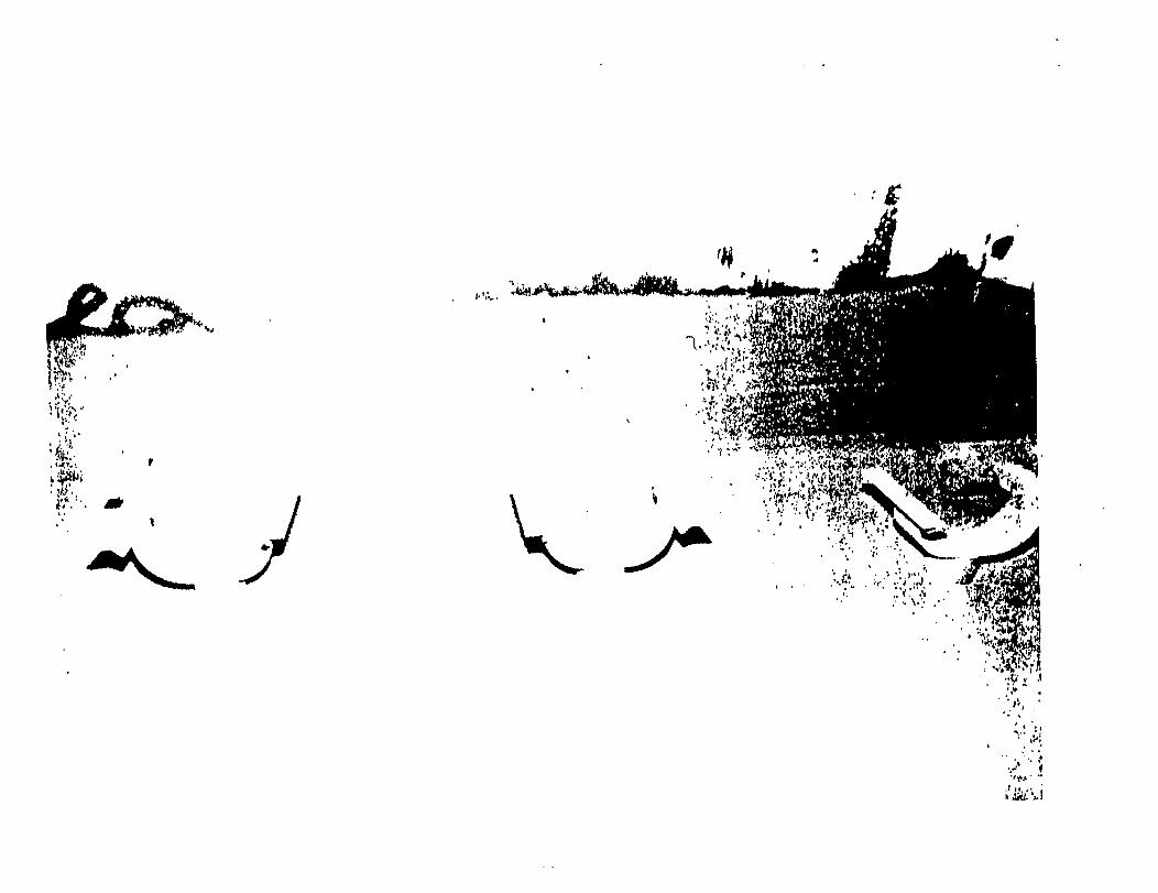


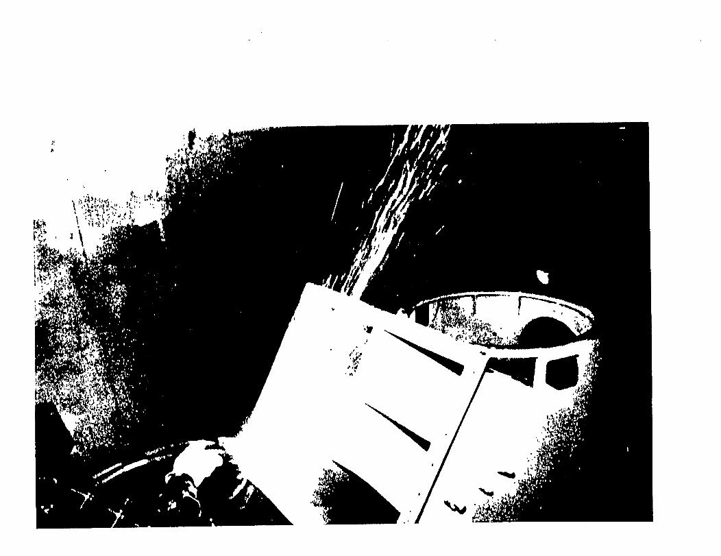

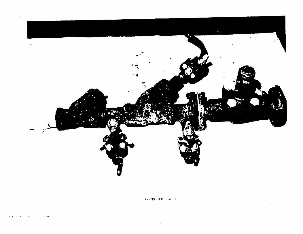
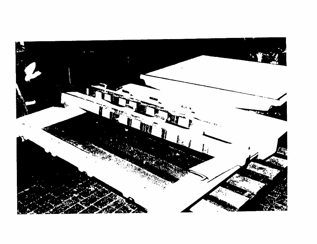

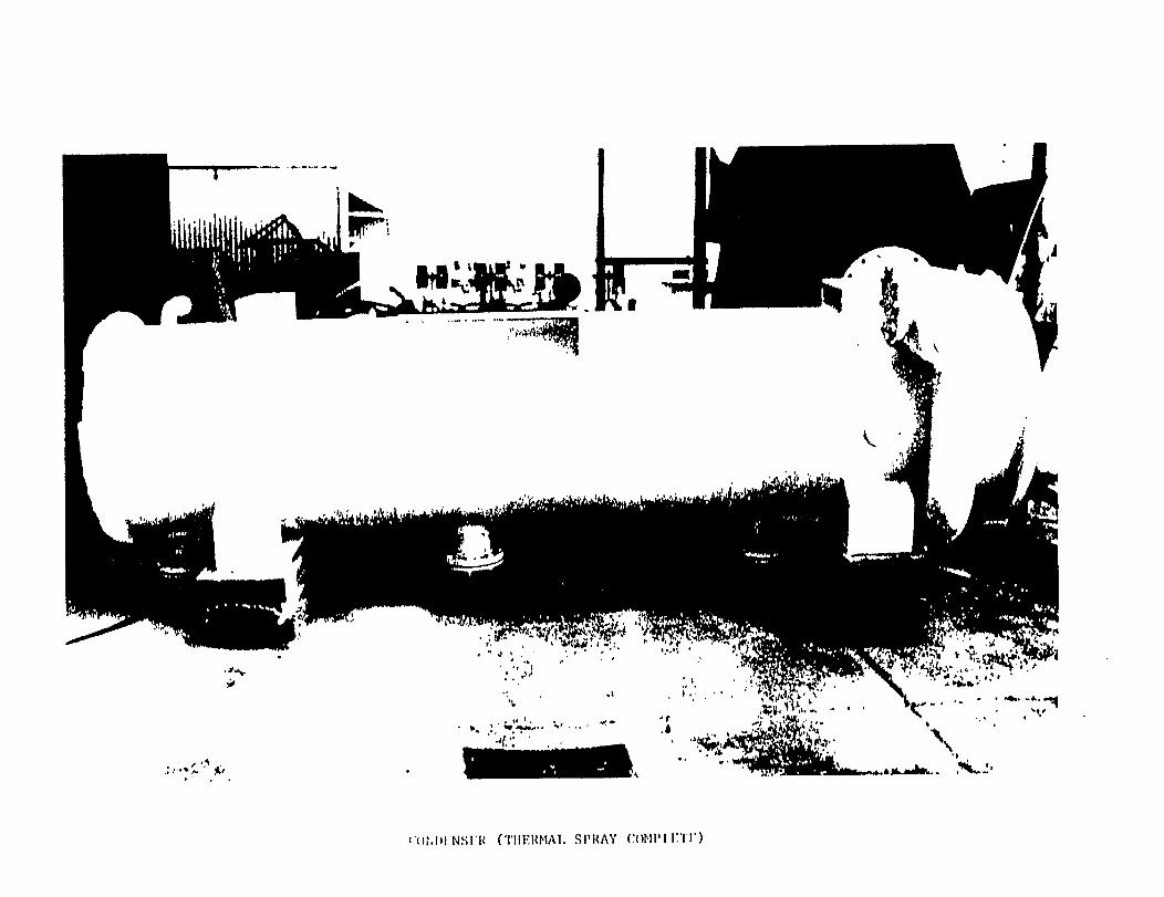


REFERENCES
1 . Arinc Report, May 1985.
2 . "Protective Coating of Iron and Steel Structures AgainstCorrosion”, British Standards Institution BS5493, 1977.
3. "SNAME Panel SP-3 Surface Preparation and Coatings Report”,1979.
4 . Chan, Michael, “Navy Compliance with VOC Regulations forMarine Coatings”, Naval Sea Systems Command.
"Painting; General Requirements and Procedures For”, PSNSProcess Instruction 0631-216A CH-3, January, 1984.
6. "The Economics of Shipboard Painting”, US Department ofTransportation, Maritime Administration.
Weismantel, “Paint Handbook”.7.
8 . Sfirri, Michael J., “Informational Package”, InorganicCoatings, Inc.
9. Military Standard DOD-STD-2138 (SH), November 1981.
10. PSNS process Instruction 0074-705 CH-3, June, 1986.
11. "Presentation of Ships in service”, Naval Ships TechnicalManual NAVSEA S9086-VD-000/Chapter 631, June, 1983.
12 . "Journal of Protective Coatings and Linings”, March, 1985.
8 1