the design, construction, and testing of an in-furrow
TRANSCRIPT
The Design, Construction, and Testing of an In-Furrow
Planter for the Planting of Low Residue Cover Crops
by
Chandler A. Bennett
Agriculture Systems Management
BioResource and Agricultural Engineering Department
California Polytechnic State University
San Luis Obispo
2014
2
TITLE : The Design, Construction, and Testing of an In-Furrow Planter
for the Planting of Low Residue Cover Crops
AUTHOR : Chandler A. Bennett
DATE SUBMITTED : February 18, 2014
Dr. Andrew J. Holtz
Senior Project Advisor Signature
Date
Art MacCarley
Department Head Signature
Date

3
ACKNOWLEDGEMENTS
First, I would like to thank Wilbur Ellis Company and specifically Joel Wiley, for
furnishing the required funds and agronomic knowledge for the creation of this project.
Second, I would like to thank the Bio Resource and Agriculture Engineering department
of the California Polytechnic school of San Luis Obispo; especially, Professor Andrew
Holtz. Professor Holtz has helped me in a multitude of ways in ensuring the success of
not only this project but also my scholastic career at Cal Poly.
Third, but most importantly, I would like to thank my parents and sisters for all of their
love and support. Without their involvement and the foundation that they have provided
me with I may have never made it to, or for that matter completed, my education at Cal
Poly.

4
ABSTRACT
This project encompasses the design, construction, and evaluation of an in-furrow planter
for the planting of low residue cover crops. The purpose of planting the furrow is for the
management of off-site removal of residual pesticides, nutrients, and soil by mitigating
water flow. Due to there being no current solution for the mechanized planting of furrows
this project was pursued to provide a means for farmers to do so at the most cost effective
means. The result of this project is a prototype planter that can be made with basic shop
tools, be made with off the shelf parts, and be adapted to a multitude of existing
agricultural implements. Also, the project includes a results and discussion section that
presents recommendations for the improvement of the current design based off the testing
results.

5
DISCLAIMER STATEMENT
The University makes it clear that the information forwarded herewith is a project
resulting from a class assignment and has been graded and accepted only as a fulfillment
of a course requirement. Acceptance by the University does not imply technical accuracy
or reliability. Any use of the information in this report is made by the user(s) at his/her
own risk, which may include catastrophic failure of the device or infringement of patent
or copyright laws.
Therefore, the recipient and/or user of the information contained in this report agrees to
indemnify, defend and save harmless the State its officers, agents and employees from
any and all claims and losses accruing or resulting to any person, firm, or corporation
who may be injured or damaged as a result of the use of this report and equipment.

6
TABLE OF CONTENTS
Page
ACKNOWLEDGEMENTS ................................................................................................ 3
ABSTRACT ........................................................................................................................ 4 DISCLAIMER STATEMENT ........................................................................................... 5 LIST OF TABLES .............................................................................................................. 9 INTRODUCTION ............................................................................................................ 10 LITERATURE REVIEW ................................................................................................. 11
Cost of Soil Erosion ...................................................................................................... 11 Types of Water Erosion ................................................................................................ 11 Principles of Erosion and Sediment Control ................................................................. 11 The Regulations ............................................................................................................ 12
Proposed Solution; Use of Cover Crop in Furrow ........................................................ 12 Types of Cover Crop ..................................................................................................... 12
Application of Seed ...................................................................................................... 12 Seed Drill. ................................................................................................................. 13
Broadcasting. ............................................................................................................ 13 Seed Metering ............................................................................................................... 14
Variable Orifice......................................................................................................... 14
Fluted Wheel. ............................................................................................................ 14 Auger. ........................................................................................................................ 15
Power Supply for Metering Units ................................................................................. 15 12 Volt Power Source. .............................................................................................. 16 Ground Drive. ........................................................................................................... 16
PROCEDURES AND METHODS................................................................................... 17
Design Constraints ........................................................................................................ 17 Design Procedure .......................................................................................................... 17 Fabrication .................................................................................................................... 18
Fabrication of Main Seed Metering Tube ................................................................. 18 Fabrication of Main frame ........................................................................................ 22
Fabrication of Seed Hopper ...................................................................................... 24 Fabrication of Scatter Plate ....................................................................................... 24
Fabrication and Assembly of PWM power source ................................................... 24 Assembly ...................................................................................................................... 25 Testing .......................................................................................................................... 28
Bench Testing ........................................................................................................... 28 Field Testing ............................................................................................................. 31
RESULTS AND DISCUSSION ....................................................................................... 32 Bench Testing ............................................................................................................... 32
In-Field Testing ............................................................................................................. 33 RECOMMENDATIONS .................................................................................................. 34
Fabrication Recommendations ..................................................................................... 34 Recommendations from Testing ................................................................................... 34 Operational Recommendations ..................................................................................... 35
Electrical ................................................................................................................... 35

7
Mechanical ................................................................................................................ 35
REFERENCES ................................................................................................................. 37 APPENDICES .................................................................................................................. 39
APPENDIX A: .............................................................................................................. 40
ASM CONTRACT & HOW PROJECT MEETS REQUIREMENTS FOR THE ASM
MAJOR ......................................................................................................................... 40 ASM Project Requirements ...................................................................................... 41 Application of Agricultural Technology: .................................................................. 41 Application of Business and/ or Management Skills: ............................................... 41
Quantitative, Analytical Problem Solving: ............................................................... 41 Capstone Project Experience: ................................................................................... 41 ASM Approach: ........................................................................................................ 42 Systems Approach: ................................................................................................... 42
Interdisciplinary Features: ........................................................................................ 42 Specialized Agricultural Knowledge: ....................................................................... 42
ASM Senior Project Contract ................................................................................... 43 APPENDIX B: .............................................................................................................. 46
Cost Breakdown ............................................................................................................ 46 Per Unit Cost Approximation ................................................................................... 47 Overall Cost of Materials Purchased ........................................................................ 48
APPENDIX C: .............................................................................................................. 49 Drawings ....................................................................................................................... 49
Main Frame Drawing ................................................................................................ 50 Hopper Frame Drawing ............................................................................................ 51 PVC Metering Tube Drawing ................................................................................... 52
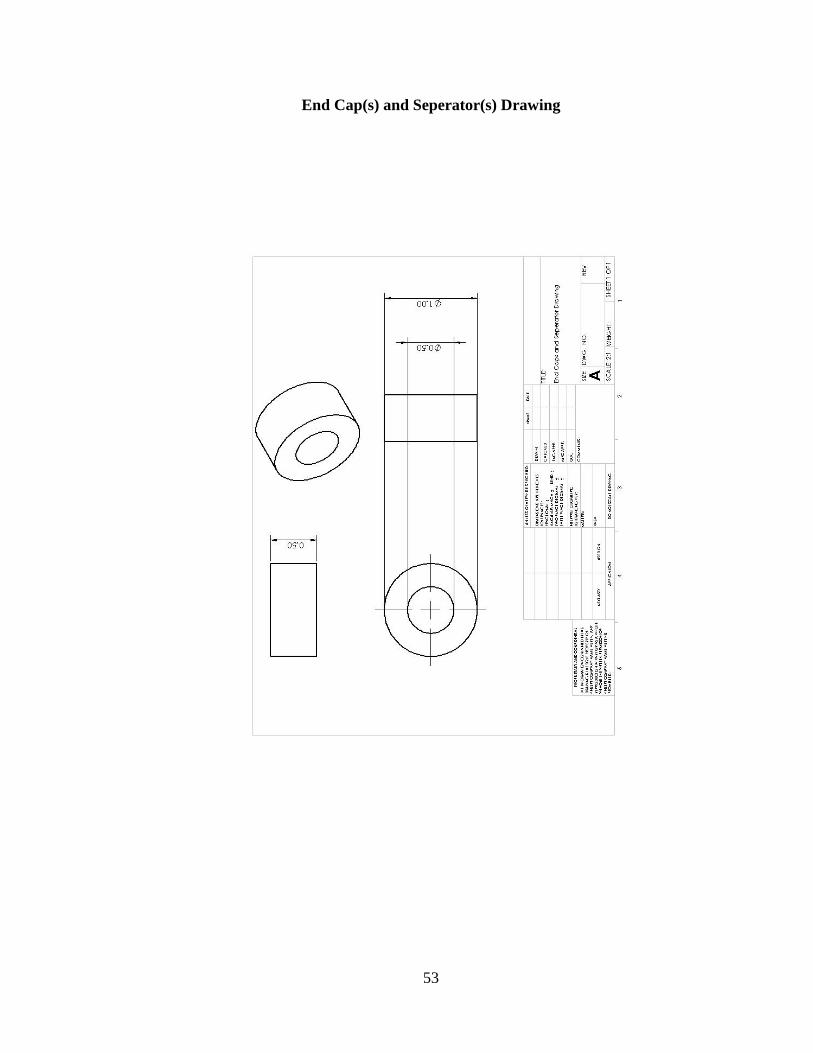
End Cap(s) and Seperator(s) Drawing ...................................................................... 53
Alternative Impeller to be 3D Printed Drawing ........................................................ 54 APPENDIX E: Data Collected from Testing .................................................................... 55
Data Collected from Output in Relation to Speed ........................................................ 56
Data Collected from Output Distribution from Scatter Plate ....................................... 57
8
LIST OF FIGURES
Page
Figure 1. The Rear of a John Deere Drill Seeder (Balewagons,2011)…………………. 13
Figure 2. P.T.O Agitated Broadcast Seeder (Solex, 2011).…………………..……….... 13
Figure 3. Example of an Agitator and Variable Orifice………………………………… 14
Figure 4. Fluted Wheel Seed Metering System (Srivastava, A. K., 2006)…………….. 15
Figure 5. Various Auger Designs Tested for Seeding (Maleki, M. R., 2006)………….. 15
Figure 6. Male ISO 1724 Connector (Frankana)……………………………………….. 16
Figure 7. Solidworks Rendering of Finalized Design………………………………...… 17
Figure 8. Impeller Used in Seed Metering Tube……………………………………...… 18
Figure 9. Finished Seperators and Caps……………………………………………...…. 19
Figure 10. PVC Main Tube with Layout……………………………………………….. 20
Figure 11. PVC Main Tube Alignment with Hole Saw………………………………… 20
Figure 12. Half Inch Schedule 40 PVC Pipe Spacers…………………………………... 21
Figure 13. Assembly of Internals of Seed Metering Tube……………………………… 21
Figure 14. Tapping of Caps and Impellers……………………………………………… 22
Figure 15. Drilled Holes for Scarifier Mounting……………………………………….. 23
Figure 16. Holes Drilled for Mounting of Eye Bolts…………………………………… 23
Figure 17. Top Bar for Securing Hopper……………………………………………….. 24
Figure 18. Plastic Enclosure Used for Housing PWM…………………………………. 25
Figure 19. PWM Enclosure Mounted during Assembly………………………………... 25
Figure 20. Washer Placement for Tensioning of Chain………………………………… 26
Figure 21. Hopper View of Coupling Pieces and Feed Tubes………………………….. 27
Figure 22. Mounting Hardware for Hopper Bucket…………………………………….. 27
Figure 23. Hardware for Attaching Chain for Drag and Scatter Plate……………….…. 28
Figure 24. Leveling of Planter for Bench Testing……………………………………… 29
Figure 25. Angle Adjustment of Scatter Plate………………………………………..… 29
Figure 26. PWM Controller Speed Markings…………...……………………………… 30
Figure 27. Collection Box and One-Inch Increments for Determining Distribution…… 30
Figure 28. Planter Mounted on Tool Bar……………………………………………….. 31
Figure 29. Scatter Plate In-Line with Shoulders of Bed………………………………... 31
Figure 30. Planting Effectiveness at Fastest Ground Speed………………...………….. 33
Figure 31. Currently Used Hay Bine Spring Tine……………………………………… 34
Figure 32. Spring Chisel (Massey Ferguson. 2014)……………………………………. 35
Figure 33. Dry Fertilizer Shank (Pacific Ag Wholesalers, Inc.. 2014)…………………. 35
Figure 34. Temporary Solution for Tensioning Chain………………………………….. 36

9
LIST OF TABLES
Page
Table 1. Total Output of Seed (oz.) per Minute at Varying Speeds……………………. 32
Table 2. Distribution of Seed from Scatter Plate……………………………………….. 33
10
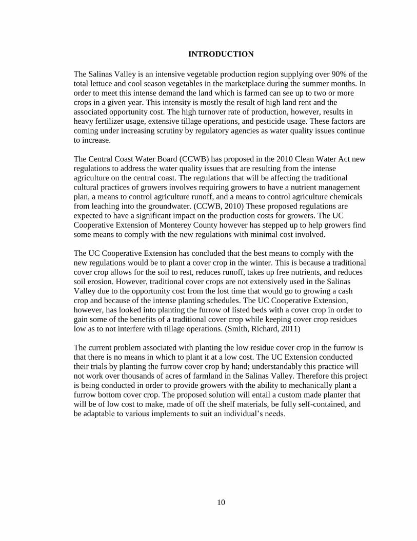
INTRODUCTION
The Salinas Valley is an intensive vegetable production region supplying over 90% of the
total lettuce and cool season vegetables in the marketplace during the summer months. In
order to meet this intense demand the land which is farmed can see up to two or more
crops in a given year. This intensity is mostly the result of high land rent and the
associated opportunity cost. The high turnover rate of production, however, results in
heavy fertilizer usage, extensive tillage operations, and pesticide usage. These factors are
coming under increasing scrutiny by regulatory agencies as water quality issues continue
to increase.
The Central Coast Water Board (CCWB) has proposed in the 2010 Clean Water Act new
regulations to address the water quality issues that are resulting from the intense
agriculture on the central coast. The regulations that will be affecting the traditional
cultural practices of growers involves requiring growers to have a nutrient management
plan, a means to control agriculture runoff, and a means to control agriculture chemicals
from leaching into the groundwater. (CCWB, 2010) These proposed regulations are
expected to have a significant impact on the production costs for growers. The UC
Cooperative Extension of Monterey County however has stepped up to help growers find
some means to comply with the new regulations with minimal cost involved.
The UC Cooperative Extension has concluded that the best means to comply with the
new regulations would be to plant a cover crop in the winter. This is because a traditional
cover crop allows for the soil to rest, reduces runoff, takes up free nutrients, and reduces
soil erosion. However, traditional cover crops are not extensively used in the Salinas
Valley due to the opportunity cost from the lost time that would go to growing a cash
crop and because of the intense planting schedules. The UC Cooperative Extension,
however, has looked into planting the furrow of listed beds with a cover crop in order to
gain some of the benefits of a traditional cover crop while keeping cover crop residues
low as to not interfere with tillage operations. (Smith, Richard, 2011)
The current problem associated with planting the low residue cover crop in the furrow is
that there is no means in which to plant it at a low cost. The UC Extension conducted
their trials by planting the furrow cover crop by hand; understandably this practice will
not work over thousands of acres of farmland in the Salinas Valley. Therefore this project
is being conducted in order to provide growers with the ability to mechanically plant a
furrow bottom cover crop. The proposed solution will entail a custom made planter that
will be of low cost to make, made of off the shelf materials, be fully self-contained, and
be adaptable to various implements to suit an individual’s needs.

11
LITERATURE REVIEW
Agriculture sediment control that will comply with government water quality regulations
necessitates the need to have an understanding as to how sediment is created and
mitigated. In addition it will be necessary to find what such regulations require. Once
such factors have been taken into account and past case studies have been analyzed, the
development of a machine can thus be pursued to secure a solution to the problem of
agriculture sediment runoff and chemical leaching.
Cost of Soil Erosion
The quality of farm land all depends upon the quality of the soil. When water flows
across soil it promotes the movement of “minerals, plant nutrients, soil particles,
agricultural chemicals, and other organic and inorganic pollutants.”(Beasley, Gregory,
and McCarty, 1984) This movement results in the degradation of agriculture land and
detrimental effects to offsite environments.
Types of Water Erosion
There are five types of soil erosion caused by water; they are sheet/rill, splash, gully, and
channel. All of these forms of water erosion exert energy upon the soil which equates to
soil translocation. The types which are generally associated with a agricultural field is the
rain drop, and sheet/rill. Of these three, the sheet/rill is considered to be the worst.
(Beasley,1984).
Sheet/rill is the type of soil movement which is the result of splash and surface runoff.
This movement removes uniformly over areas and thus can go unnoticed. The effect of
this movement on the soil all depends upon the “velocity, turbulence, and the amount and
type of abrasive material it transports.”(Beasley, 1984).
Principles of Erosion and Sediment Control
The following are the basic processes which should be utilized to reduce sediment runoff:
1. Fit tillage operations to the terrain.
2. Time agriculture activities to minimize soil exposure.
3. Retain existing vegetation whenever feasible.
4. Vegetate/ mulch denuded areas.
5. Divert runoff from denuded areas.
6. Minimize length and steepness of slopes.
7. Keep runoff velocities low.
8. Trap sediment on site.
(Goldman, Jackson, and Bursztynsky, 1986)

12
The Regulations
The Central Coast Waterboard is in the process of implementing regulations pertaining to
agriculture runoff. Such regulations pertain that growers have sediment management
practices which will address:
Sediment discharges through source control, pollution prevention practices, or
technical mitigations that are feasible in commercial agriculture production
systems, if applicable.
Control of sediment shall be consistent with Food Safety requirements as
applicable to individual growers.
Reduction of nitrate runoff and leaching.
Reduction of pesticide mobility offsite.
(Central Coast Waterboard, 2010)
Proposed Solution; Use of Cover Crop in Furrow
To reduce sediment from fallow pre-shaped vegetable beds in agriculture fields the
proposed solution is to use a low residue cover crop in the furrow. Planting in the furrow
will mitigate the common nuisances of managing a traditional cover crop. An example of
such nuisances is the problem of “hair pinning” which is the accumulation of residue on
planting units which thus can cause problems with the establishment of the cash crop.
(Kornecki, T. S., Price, A. J., Arriaga, F. J., Balkcom, K. S.. 2010.). Therefore the
proposed furrow cover cropping will act as a way to vegetate the furrow, trap sediment
coming from the shaped beds, reduce splash impact, and keep runoff velocities low; all
the while keeping fields relatively clean from the cover crop residue. In addition the
furrow cover crop will uptake available nutrients within the root zone of the cover crop.
Types of Cover Crop
The University of California Cooperative Extension in Monterey County has done tests
on various types of vegetation and their effectiveness in controlling sediment from
agriculture fields. The tests of winter dormant ‘888’ triticale and ‘Merced’ cereal rye
planted in furrow bottoms have shown to have 2.3 and 9.2% runoff compared to bare
furrow treatments having as much as 47.2% runoff. (Smith, Richard, Cahn, Michael,
Heinrich, Aaron, Farrara, Barry. 2011). The cereal rye has shown however to be superior
to that of the triticale.
Application of Seed
There are many types of mechanical seed sowing devices. From reviewing the multiple
devices associated with planting cover crops the dominate seed planters for such an
application are seed drills or broadcasting seeders. With the evaluation of the previous,
the proposed seeder will incorporate the strengths of each for the construction of a
specialty mechanical seeder for the application of seed within the confines of the furrow.
Therefore research has been completed for design considerations for such an application.

13
Seed Drill. The seed drill has been used for cover cropping in agriculture for many years.
This is due to the seed drill being capable of having a large field capacity due to its
overall effective width and having a large seed holding volume. (F.E, Dowell., 1986) In
addition the use of a seed drill directly applies the seed at a given depth and then covers it
with soil. This process keeps the seed from being removed by natural forces and ensuring
good soil to seed contact. This ensures the efficient use of seed and promotes excellent
germination.
Fig. 1. The Rear of a John Deere Drill Seeder (Balewagons, 2011).
Broadcasting. The broadcasting of seed has been done either by hand or with the use of a
broadcast seeder. A broadcast seeder works by first metering the seed from the hopper
via a variable orifice or a fluted wheel. Once the seed has been metered in some fashion it
then proceeds to drop onto a spinning disk. The powered disk throws the seed by exerting
centrifugal force on the seed. (Srivastava, A. K., Goering, C. E, Rohbach, R. P, and
Buckmaster, D. R. 2006.) The planting width in which the seed is broadcasted “depends
upon the size, shape, and density of the seeds. (Srivastava, A.K. 2006.) Some
broadcasters however have the ability to manipulate the width of coverage by controlling
the opening in which the seed may exit the spinning plate.
Figure 2. P.T.O Agitated Broadcast Seeder (Solex, 2011).

14
The method of broadcasting material is very efficient at spreading large quantities of seed
but lacks certain aspects. Such aspects include the lack of the ability to insert the seed
into the soil and the lack of precise seeding rates. These deficient characteristics of the
seeder result in the prospect of subprime plant population from elements which are not
beneficial to germination such as low humidity, poor soil to seed contact, wildlife
foraging, wind, and runoff.
Seed Metering
The design constraints of this project require that the seeding unit have the capability of
having an adjustable seeding rate. The ability to adjust a seeding rate would be from the
use of seed metering. Seed metering is “the number of seeds that are released from the
hopper per unit of time.”( Srivastava, A. K., Goering, C. E, Rohbach, R. P, and
Buckmaster, D. R. 2006.) From the exploration of various seed metering designs the most
practical for this application would be that of variable orifice or a fluted wheel. These
metering devices are also generally accompanied by an agitator to provide a steady flow
of the seed from the seed hopper.
Variable Orifice. The metering of seeds via variable orifice is one of the oldest methods
and is still commonly used today. The metering of the seed is controlled by the changing
of the size of the orifice size and the reliance on gravity. The size of the orifice has a
direct relationship with the volumetric flow rate of the seed. ( Srivastava, A. K., 2006) In
order to keep the seed from “bridging” the use
Figure 3. Example of an Agitator and Variable Orifice (Srivastava, A. K., 2006).
of an agitator is used to keep a steady flow from the seed hopper. The agitator is powered
by either a power unit or ground drive. An example of a variable orifice and agitator can
be found in figure three above.
Fluted Wheel. A fluted wheel system of seed metering provides for greater accuracy in
seeding rates. The greater accuracy is because a fluted wheel uses a power source to
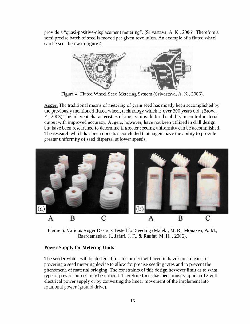
15
provide a “quasi-positive-displacement metering”. (Srivastava, A. K., 2006). Therefore a
semi precise batch of seed is moved per given revolution. An example of a fluted wheel
can be seen below in figure 4.
Figure 4. Fluted Wheel Seed Metering System (Srivastava, A. K., 2006).
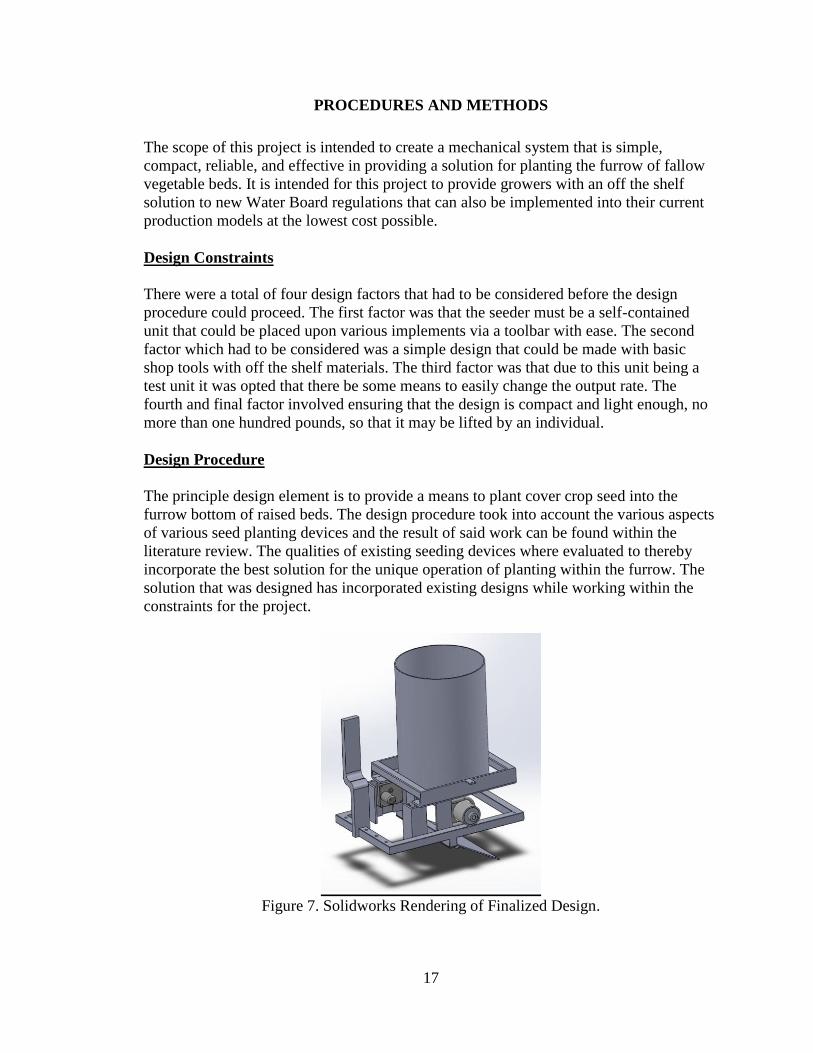
Auger. The traditional means of metering of grain seed has mostly been accomplished by
the previously mentioned fluted wheel, technology which is over 300 years old. (Brown
E., 2003) The inherent characteristics of augers provide for the ability to control material
output with improved accuracy. Augers, however, have not been utilized in drill design
but have been researched to determine if greater seeding uniformity can be accomplished.
The research which has been done has concluded that augers have the ability to provide
greater uniformity of seed dispersal at lower speeds.
Figure 5. Various Auger Designs Tested for Seeding (Maleki, M. R., Mouazen, A. M.,
Baerdemaeker, J., Jafari, J. F., & Raufat, M. H. , 2006).
Power Supply for Metering Units
The seeder which will be designed for this project will need to have some means of
powering a seed metering device to allow for precise seeding rates and to prevent the
phenomena of material bridging. The constraints of this design however limit as to what
type of power sources may be utilized. Therefore focus has been mostly upon an 12 volt
electrical power supply or by converting the linear movement of the implement into
rotational power (ground drive).

16
12 Volt Power Source. All modern equipment today has some form of electrical power
onboard. For the most part this is in the form of twelve volts of direct current (D.C). This
power is generally created by an engine mounted alternator which provides power to “all
on-board electrical loads, lights, electronic control units, etc.” (Stoss, Kenneth J., Joachim
Sobotzik, Bin Shi, and Edwin R. Kreis. 2013.) Power which is provided to agriculture
implements and/or accessories on a twelve volt basis is generally provided by an ISO
1724 connector per the International Organization for Standardization or one merely
directly connecting to onboard battery posts. The limitations of the available current
(amps) is directly related to the capability of the alternator. (Stoss, 2013)
Figure 6. Male ISO 1724 Connector (Frankana).
Ground Drive. Ground drive has been used in agriculture to power implements for quit
sometime. A ground engaging wheel is used to transmit power to a planters given seed
metering device. This form of power provides for a direct correlation between seed
metering revolutions and time/distance. Therefore if the unit slows down so does the seed
output rate and vice versa. In order to change seeding rates for a given speed some
seeders are equipped with different drive sprocket sizes in order to accommodate
different drive ratios. ( Srivastava, A. K., 2006) This form of power provides for
consistency regardless of changing factors on the seed metering device such as friction,
varying weight of total seed in hopper, etc. (Holtz, 2013) However, care must be taken to
ensure that the drive wheel has limited wheel slippage and tire pressures are correct in
order to ensure uniformity of seed metering.
17
PROCEDURES AND METHODS
The scope of this project is intended to create a mechanical system that is simple,
compact, reliable, and effective in providing a solution for planting the furrow of fallow
vegetable beds. It is intended for this project to provide growers with an off the shelf
solution to new Water Board regulations that can also be implemented into their current
production models at the lowest cost possible.
Design Constraints
There were a total of four design factors that had to be considered before the design
procedure could proceed. The first factor was that the seeder must be a self-contained
unit that could be placed upon various implements via a toolbar with ease. The second
factor which had to be considered was a simple design that could be made with basic
shop tools with off the shelf materials. The third factor was that due to this unit being a
test unit it was opted that there be some means to easily change the output rate. The
fourth and final factor involved ensuring that the design is compact and light enough, no
more than one hundred pounds, so that it may be lifted by an individual.
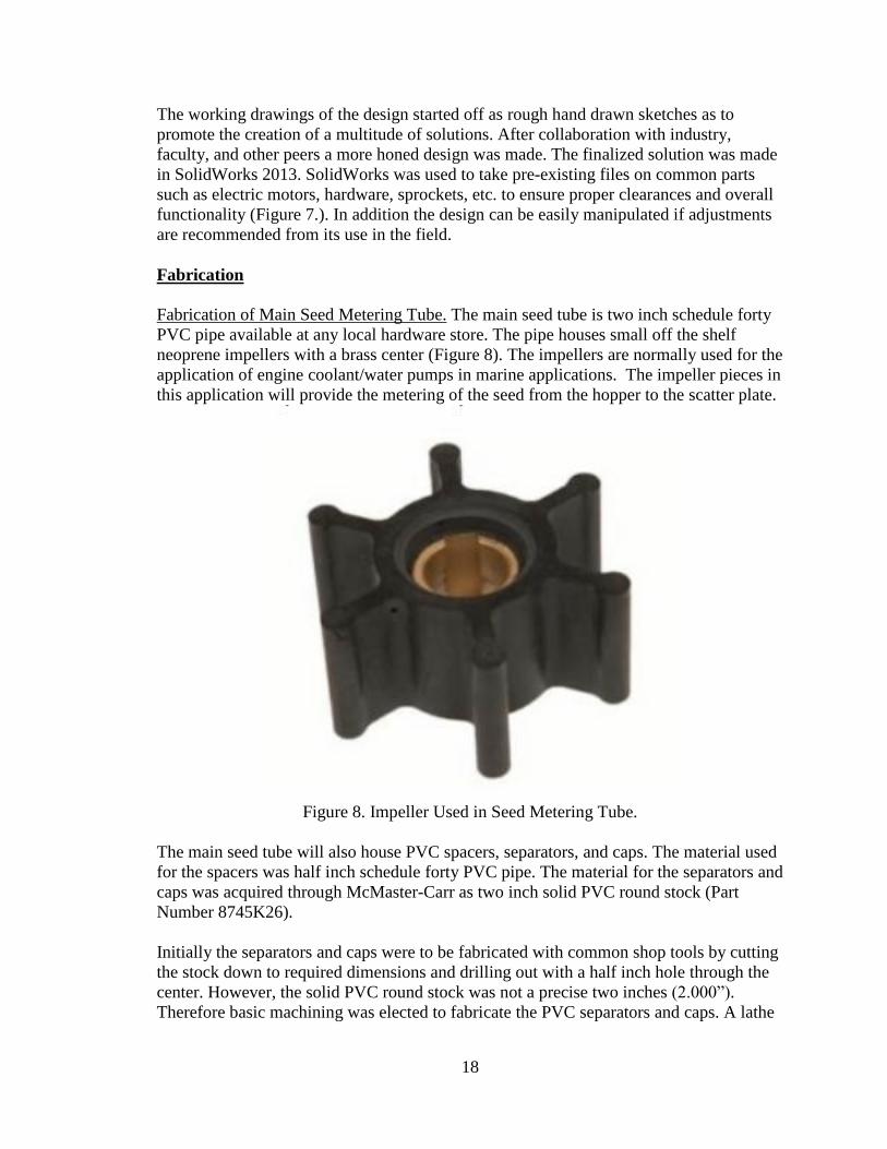
Design Procedure
The principle design element is to provide a means to plant cover crop seed into the
furrow bottom of raised beds. The design procedure took into account the various aspects
of various seed planting devices and the result of said work can be found within the
literature review. The qualities of existing seeding devices where evaluated to thereby
incorporate the best solution for the unique operation of planting within the furrow. The
solution that was designed has incorporated existing designs while working within the
constraints for the project.
Figure 7. Solidworks Rendering of Finalized Design.
18
The working drawings of the design started off as rough hand drawn sketches as to
promote the creation of a multitude of solutions. After collaboration with industry,
faculty, and other peers a more honed design was made. The finalized solution was made
in SolidWorks 2013. SolidWorks was used to take pre-existing files on common parts
such as electric motors, hardware, sprockets, etc. to ensure proper clearances and overall
functionality (Figure 7.). In addition the design can be easily manipulated if adjustments
are recommended from its use in the field.
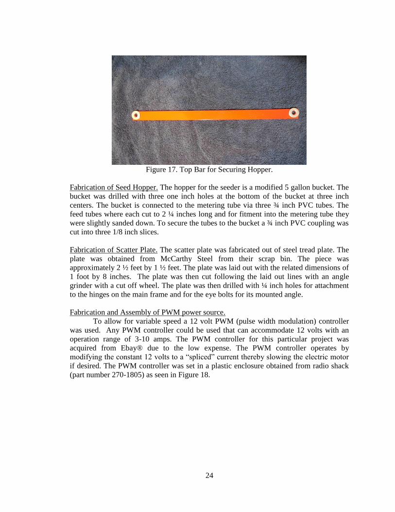
Fabrication
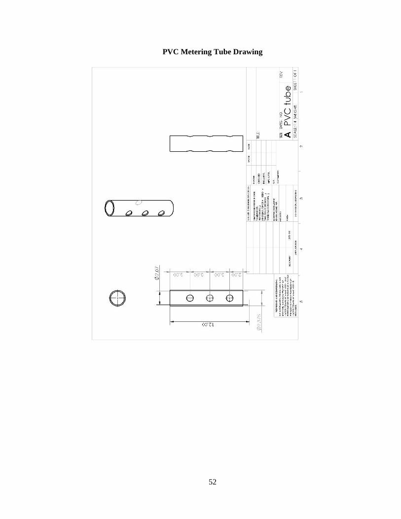
Fabrication of Main Seed Metering Tube. The main seed tube is two inch schedule forty
PVC pipe available at any local hardware store. The pipe houses small off the shelf
neoprene impellers with a brass center (Figure 8). The impellers are normally used for the
application of engine coolant/water pumps in marine applications. The impeller pieces in
this application will provide the metering of the seed from the hopper to the scatter plate.
Figure 8. Impeller Used in Seed Metering Tube.
The main seed tube will also house PVC spacers, separators, and caps. The material used
for the spacers was half inch schedule forty PVC pipe. The material for the separators and
caps was acquired through McMaster-Carr as two inch solid PVC round stock (Part
Number 8745K26).
Initially the separators and caps were to be fabricated with common shop tools by cutting
the stock down to required dimensions and drilling out with a half inch hole through the
center. However, the solid PVC round stock was not a precise two inches (2.000”).
Therefore basic machining was elected to fabricate the PVC separators and caps. A lathe

19
was used to turn down the PVC solid round stock to a precise two inches to thereby
ensure a good fit within the schedule forty two inch PVC seed tube.
Figure 9. Finished Separators and Caps.
Once the stock was turned down, the stock was drilled with a half inch drill bit, also on
the lathe. The final action on the lathe was parting out the PVC stock to the required
dimensions for the separators and caps. The finished separators and caps can be seen in
Figure 9. It must be noted that these parts could also have been made with a 3d printer
either by one’s self or done by a 3d printing service. Using 3d printing technology to
create a few of these pieces (but not for mass manufacturing) could be done at a cheaper
rate than machining.
The next step to fabricating and assembling the main seed tube was drilling out the input
and output holes through the PVC main tube. The process was done on a drill press with
a one inch hole saw. The measurement was done by taking a square to find center on top
of the tube. A line was then drawn as to provide a reference line for the placement of the
holes as seen in Figure 10.
As seen in Figure 11 the center of the holes was set for drilling the PVC main tube. The
hole cut through the top of the tube was very precise; however, the hole at the bottom was
somewhat off of the center line. This, however, is considered to be acceptable due to the
bottom hole being the output for the seed and merely being a means to deliver seed to the
scatter plate.

20
Figure 10. PVC Main Tube with Layout.
Figure 11. PVC Main Tube Alignment with Hole Saw.
The input and output holes in the tube allowed for observing correct fit and alignment of
the parts within. Therefore, the next process was the fabrication of the PVC spacers. The
spacers, as previously mentioned, were made from half inch schedule forty PVC pipe.
The pipe was cut down with a bandsaw to the desired lengths to create the desired
spacing between the separators as seen in Figure 12.

21
Figure 12. Half Inch Schedule 40 PVC Pipe Spacers.
The completion of the spacers thereby allowed for the proper spacing and fit within the
main seed tube, as seen in Figure 13. Once everything was inline with the input holes,
additional drilling was done to the various pieces within the main tube.
Figure 13. Assembly of Internals of Seed Metering Tube.
The impellers for the seeder were initially going to be driven with a keyway between the
driveshaft and the impellers. Although this process would have been satisfactory, it was
determined that an offset amongst the impellers would create a more uniform unloading
of the seed from the hopper. In order for the previous to be accomplished the keyway slot

22
on the impeller could not be used. In order to provide engagement between the impellers
and the drive shaft, holes were drilled and tapped through each impeller to provide for a
set screw. The set screws (¼ inch by 3/8 inch) from a hardware store would thereby
provide the means to engage the impellers with the drive shaft.
Figure 14. Tapping of Caps and Impellers.
In order to keep the parts within the tube contained, caps were bolted in at each end of the
tube. This was accomplished using the center reference line on the top and bottom of the
tube to provide a reference for the drilling of the holes for the set screws (¼ inch by 3/8
inch) from a hardware store which would tie together the caps with the tube. The holes
drilled were then tapped with a tap (1/4”-20). The caps where then attached to either end
with the set screws.
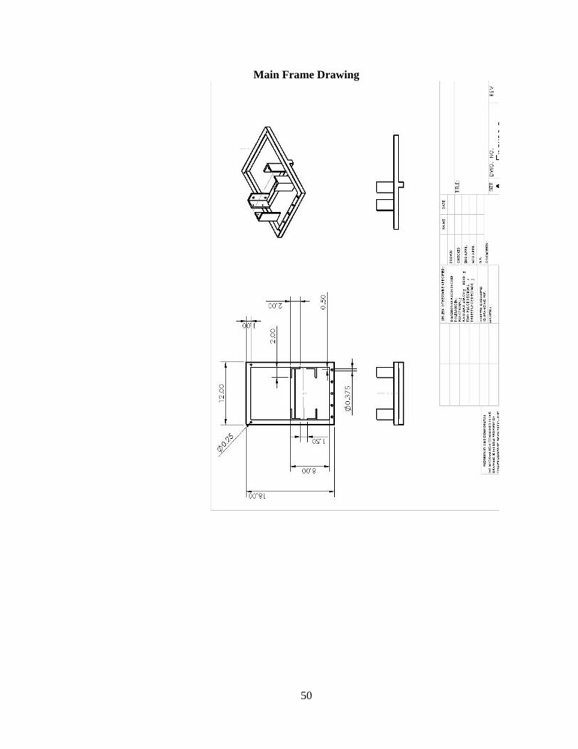
Fabrication of Main frame. The whole frame for the seeder is made of 1x1 inch HSS
tubing with .120 inch wall. The tubing was chosen in order to keep the frame light yet
rigid enough for the front scarifiers. The square tubing was bought from McCarthy Steel
of San Luis Obispo, California. The steel was cut using a cut off saw, although it could be
cut with any other metal cutting saw. The ends of each piece of tubing were cut with a
forty-five degree angle for the corners to keep foreign material out of the inside of the
tubing as to permit longer life of the steel. The piece which is at the front of the unit was
drilled with 3/8 inch holes to thereby accommodate the mounting of the scarifiers as seen
in Figure 15. The rear piece of the unit was drilled with ¼ inch size holes to
accommodate two eye bolts as seen in Figure 16. Once the tubing was all cut and drilled
it was welded together with a MIG welder.

23
Figure 15. Drilled Holes for Scarifier Mounting.
Figure 16. Holes Drilled for Mounting of Eye Bolts.
The mounts for the main tube, motor, and hopper frame where made from ¼ inch by 2
inch by 2 inch angle iron; also acquired from McCarthy Steel of San Luis Obispo, CA.
The mounts where all cut into 4 ½ inch long pieces. Two of the mounts are drilled to
accommodate the electric 12 volt gear motor which was obtained from McMaster Carr
(part number 6409K17). The angle iron mounts were then MIG welded to the main frame
per the specs seen in the design (Appendix C).
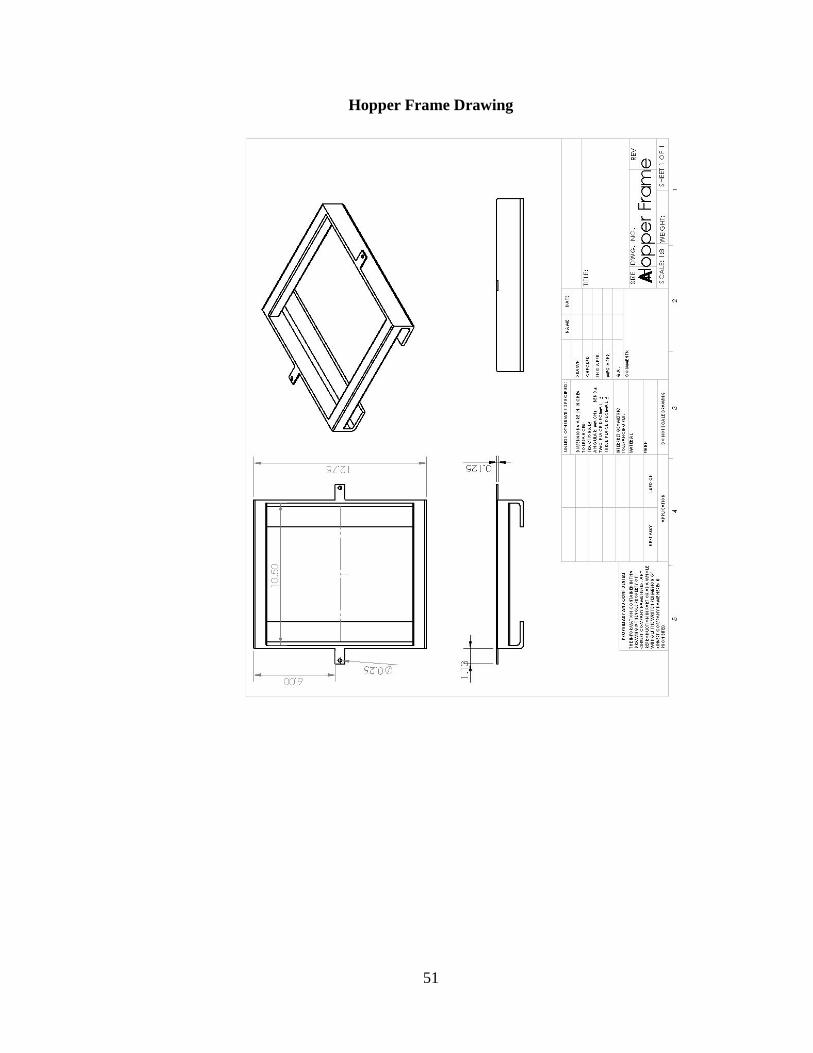
The hopper frame was designed to hold a five gallon bucket. This was accomplished by
the use of 1x1 inch HSS tubing with .0625 inch wall and ¼ inch by 2 inch by 2 inch angle
iron. Once independently fabricated from the main frame, the hopper frame was then
welded onto the main frame per the specifications in the design. To accommodate the
securing of the hopper to the hopper frame two pieces of one inch long by 1/8 inch thick
flat stock were cut and then drilled with a ¼ inch size hole. The pieces where then welded
on at the center of the left and right of the hopper frame. The previous pieces then
accommodate the securing of the bucket hopper with two 16 inch x ¼ inch all thread rod
with a top 1 inch by 1/8 inch flat bar cut to 13 inches and drilled with two ¼ inch size
holes. Figure 17 shows the completed top bar to secure the hopper.
24
Figure 17. Top Bar for Securing Hopper.
Fabrication of Seed Hopper. The hopper for the seeder is a modified 5 gallon bucket. The
bucket was drilled with three one inch holes at the bottom of the bucket at three inch
centers. The bucket is connected to the metering tube via three ¾ inch PVC tubes. The
feed tubes where each cut to 2 ¼ inches long and for fitment into the metering tube they
were slightly sanded down. To secure the tubes to the bucket a ¾ inch PVC coupling was
cut into three 1/8 inch slices.
Fabrication of Scatter Plate. The scatter plate was fabricated out of steel tread plate. The
plate was obtained from McCarthy Steel from their scrap bin. The piece was
approximately 2 ½ feet by 1 ½ feet. The plate was laid out with the related dimensions of
1 foot by 8 inches. The plate was then cut following the laid out lines with an angle
grinder with a cut off wheel. The plate was then drilled with ¼ inch holes for attachment
to the hinges on the main frame and for the eye bolts for its mounted angle.
Fabrication and Assembly of PWM power source.
To allow for variable speed a 12 volt PWM (pulse width modulation) controller
was used. Any PWM controller could be used that can accommodate 12 volts with an
operation range of 3-10 amps. The PWM controller for this particular project was
acquired from Ebay® due to the low expense. The PWM controller operates by
modifying the constant 12 volts to a “spliced” current thereby slowing the electric motor
if desired. The PWM controller was set in a plastic enclosure obtained from radio shack
(part number 270-1805) as seen in Figure 18.
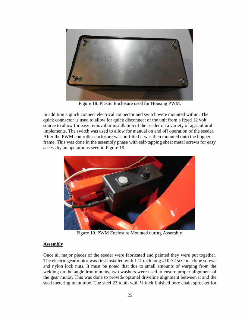
25
Figure 18. Plastic Enclosure used for Housing PWM.
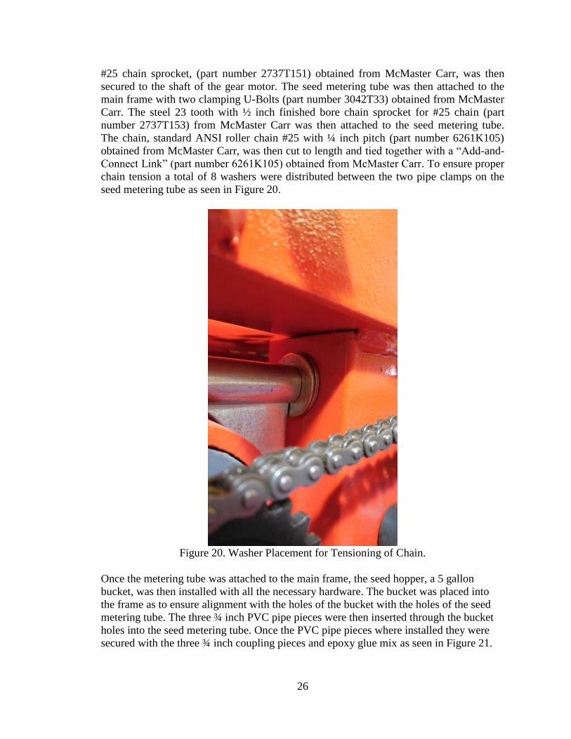
In addition a quick connect electrical connector and switch were mounted within. The
quick connector is used to allow for quick disconnect of the unit from a fixed 12 volt
source to allow for easy removal or installation of the seeder on a variety of agricultural
implements. The switch was used to allow for manual on and off operation of the seeder.
After the PWM controller enclosure was outfitted it was then mounted onto the hopper
frame. This was done in the assembly phase with self-tapping sheet metal screws for easy
access by an operator as seen in Figure 19.
Figure 19. PWM Enclosure Mounted during Assembly.
Assembly
Once all major pieces of the seeder were fabricated and painted they were put together.
The electric gear motor was first installed with 1 ¼ inch long #10-32 size machine screws
and nylon lock nuts. It must be noted that due to small amounts of warping from the
welding on the angle iron mounts, two washers were used to ensure proper alignment of
the gear motor. This was done to provide optimal driveline alignment between it and the
seed metering main tube. The steel 23 tooth with ¼ inch finished bore chain sprocket for
26
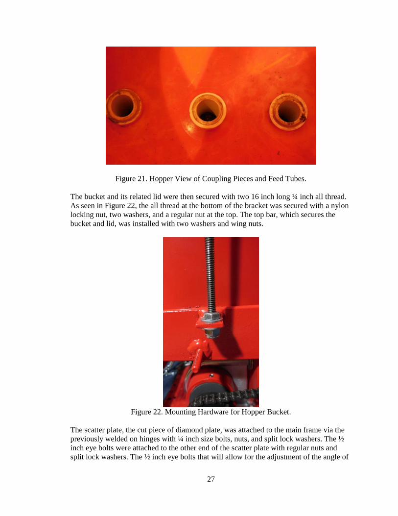
#25 chain sprocket, (part number 2737T151) obtained from McMaster Carr, was then
secured to the shaft of the gear motor. The seed metering tube was then attached to the
main frame with two clamping U-Bolts (part number 3042T33) obtained from McMaster
Carr. The steel 23 tooth with ½ inch finished bore chain sprocket for #25 chain (part
number 2737T153) from McMaster Carr was then attached to the seed metering tube.
The chain, standard ANSI roller chain #25 with ¼ inch pitch (part number 6261K105)
obtained from McMaster Carr, was then cut to length and tied together with a “Add-and-
Connect Link” (part number 6261K105) obtained from McMaster Carr. To ensure proper
chain tension a total of 8 washers were distributed between the two pipe clamps on the
seed metering tube as seen in Figure 20.
Figure 20. Washer Placement for Tensioning of Chain.
Once the metering tube was attached to the main frame, the seed hopper, a 5 gallon
bucket, was then installed with all the necessary hardware. The bucket was placed into
the frame as to ensure alignment with the holes of the bucket with the holes of the seed
metering tube. The three ¾ inch PVC pipe pieces were then inserted through the bucket
holes into the seed metering tube. Once the PVC pipe pieces where installed they were
secured with the three ¾ inch coupling pieces and epoxy glue mix as seen in Figure 21.
27
Figure 21. Hopper View of Coupling Pieces and Feed Tubes.
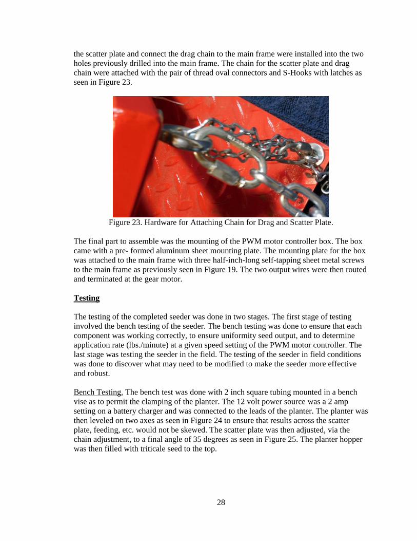
The bucket and its related lid were then secured with two 16 inch long ¼ inch all thread.
As seen in Figure 22, the all thread at the bottom of the bracket was secured with a nylon
locking nut, two washers, and a regular nut at the top. The top bar, which secures the
bucket and lid, was installed with two washers and wing nuts.
Figure 22. Mounting Hardware for Hopper Bucket.
The scatter plate, the cut piece of diamond plate, was attached to the main frame via the
previously welded on hinges with ¼ inch size bolts, nuts, and split lock washers. The ½
inch eye bolts were attached to the other end of the scatter plate with regular nuts and
split lock washers. The ½ inch eye bolts that will allow for the adjustment of the angle of
28
the scatter plate and connect the drag chain to the main frame were installed into the two
holes previously drilled into the main frame. The chain for the scatter plate and drag
chain were attached with the pair of thread oval connectors and S-Hooks with latches as
seen in Figure 23.
Figure 23. Hardware for Attaching Chain for Drag and Scatter Plate.
The final part to assemble was the mounting of the PWM motor controller box. The box
came with a pre- formed aluminum sheet mounting plate. The mounting plate for the box
was attached to the main frame with three half-inch-long self-tapping sheet metal screws
to the main frame as previously seen in Figure 19. The two output wires were then routed
and terminated at the gear motor.
Testing
The testing of the completed seeder was done in two stages. The first stage of testing
involved the bench testing of the seeder. The bench testing was done to ensure that each
component was working correctly, to ensure uniformity seed output, and to determine
application rate (lbs./minute) at a given speed setting of the PWM motor controller. The
last stage was testing the seeder in the field. The testing of the seeder in field conditions
was done to discover what may need to be modified to make the seeder more effective
and robust.
Bench Testing. The bench test was done with 2 inch square tubing mounted in a bench
vise as to permit the clamping of the planter. The 12 volt power source was a 2 amp
setting on a battery charger and was connected to the leads of the planter. The planter was
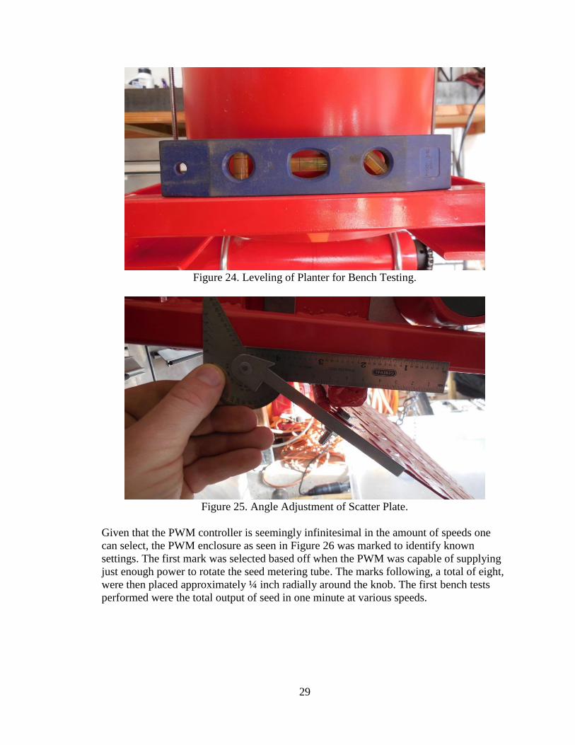
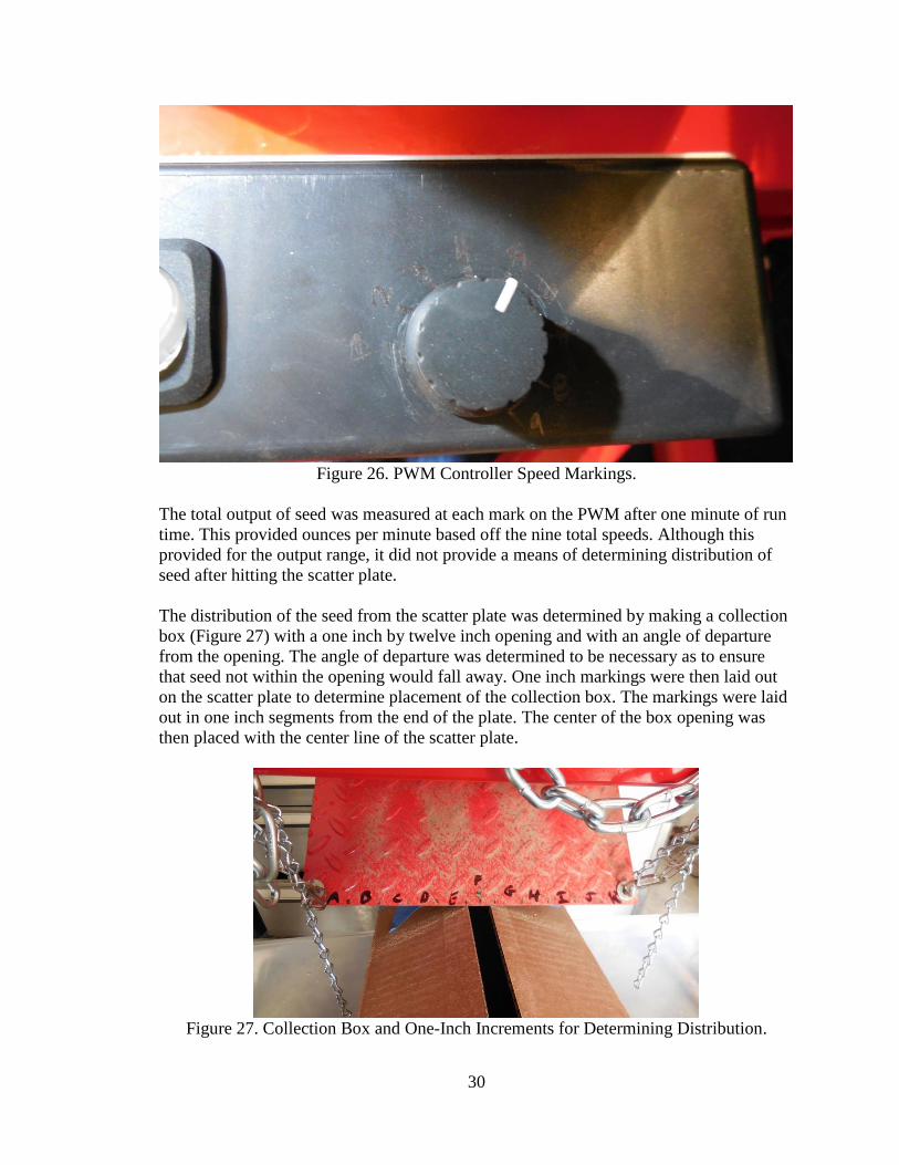
then leveled on two axes as seen in Figure 24 to ensure that results across the scatter
plate, feeding, etc. would not be skewed. The scatter plate was then adjusted, via the
chain adjustment, to a final angle of 35 degrees as seen in Figure 25. The planter hopper
was then filled with triticale seed to the top.
29
Figure 24. Leveling of Planter for Bench Testing.
Figure 25. Angle Adjustment of Scatter Plate.
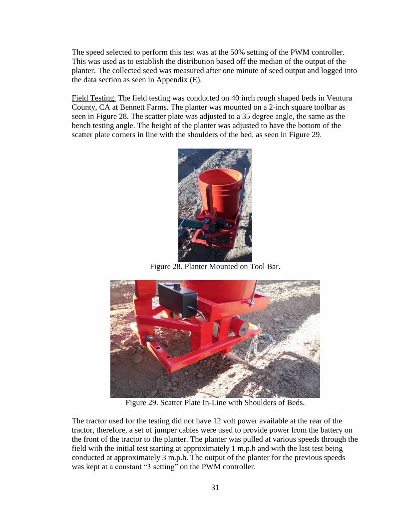
Given that the PWM controller is seemingly infinitesimal in the amount of speeds one
can select, the PWM enclosure as seen in Figure 26 was marked to identify known
settings. The first mark was selected based off when the PWM was capable of supplying
just enough power to rotate the seed metering tube. The marks following, a total of eight,
were then placed approximately ¼ inch radially around the knob. The first bench tests
performed were the total output of seed in one minute at various speeds.
30
Figure 26. PWM Controller Speed Markings.
The total output of seed was measured at each mark on the PWM after one minute of run
time. This provided ounces per minute based off the nine total speeds. Although this
provided for the output range, it did not provide a means of determining distribution of
seed after hitting the scatter plate.
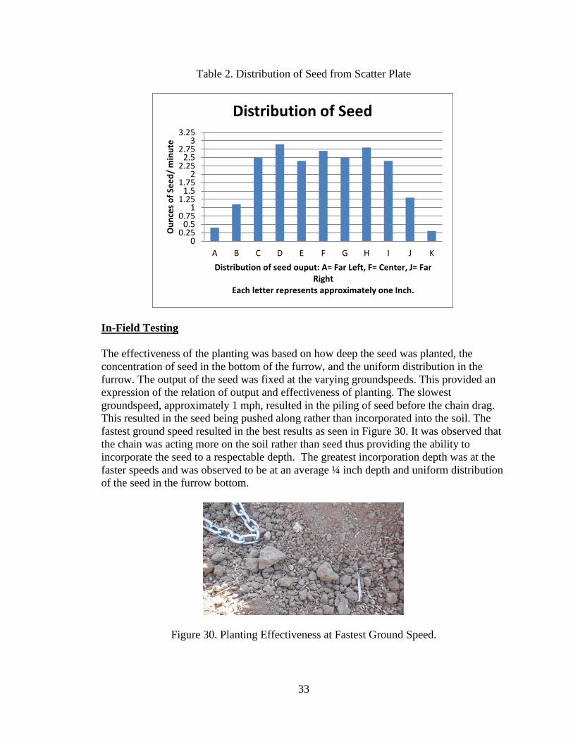
The distribution of the seed from the scatter plate was determined by making a collection
box (Figure 27) with a one inch by twelve inch opening and with an angle of departure
from the opening. The angle of departure was determined to be necessary as to ensure
that seed not within the opening would fall away. One inch markings were then laid out
on the scatter plate to determine placement of the collection box. The markings were laid
out in one inch segments from the end of the plate. The center of the box opening was
then placed with the center line of the scatter plate.
Figure 27. Collection Box and One-Inch Increments for Determining Distribution.
31
The speed selected to perform this test was at the 50% setting of the PWM controller.
This was used as to establish the distribution based off the median of the output of the
planter. The collected seed was measured after one minute of seed output and logged into
the data section as seen in Appendix (E).
Field Testing. The field testing was conducted on 40 inch rough shaped beds in Ventura
County, CA at Bennett Farms. The planter was mounted on a 2-inch square toolbar as
seen in Figure 28. The scatter plate was adjusted to a 35 degree angle, the same as the
bench testing angle. The height of the planter was adjusted to have the bottom of the
scatter plate corners in line with the shoulders of the bed, as seen in Figure 29.
Figure 28. Planter Mounted on Tool Bar.
Figure 29. Scatter Plate In-Line with Shoulders of Beds.
The tractor used for the testing did not have 12 volt power available at the rear of the
tractor, therefore, a set of jumper cables were used to provide power from the battery on
the front of the tractor to the planter. The planter was pulled at various speeds through the
field with the initial test starting at approximately 1 m.p.h and with the last test being
conducted at approximately 3 m.p.h. The output of the planter for the previous speeds
was kept at a constant “3 setting” on the PWM controller.

32
RESULTS AND DISCUSSION
Bench Testing
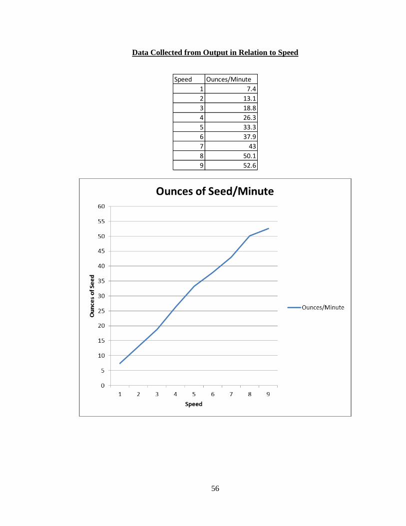
The range of revolutions per minute (R.P.M) that the planter is capable of was observed
to range from 4 R.P.M to 33.3 R.P.M. It was then determined that with this range the
planter was capable of outputting 7.4 ounces of seed at 4 R.P.M and 52.6 ounces of seed
at 33.3 R.P.M.. This was based off the relatively linear output of seed in relation to speed
as seen in Table 1. The total range of output is 7.4 ounces per minute to 52.6 ounces per
minute.
Table 1. Total Output of Seed (oz.) per Minute at Varying Speeds
The distribution test results reveal that the distribution along the 3.5 inches on either side
of center has a close tolerance of approximately .25 - .35 ounces and then tapering off
from the previously mentioned distance from center (Table 2). Given that the purpose of
the planter is to plant specifically the furrow bottom, rather than the shoulders of beds,
this was considered to be an acceptable distribution. However, testing in field would later
determine if a tighter distribution near the center would be required.
0
5
10
15
20
25
30
35
40
45
50
55
60
1 2 3 4 5 6 7 8 9
Ou
nce
s o
f Se
ed
/ M
inu
te
Speed Setting on PWM
Calibration: Seed Application vs. PWM Speed Setting
Ounces/Minute
33
Table 2. Distribution of Seed from Scatter Plate
In-Field Testing
The effectiveness of the planting was based on how deep the seed was planted, the
concentration of seed in the bottom of the furrow, and the uniform distribution in the
furrow. The output of the seed was fixed at the varying groundspeeds. This provided an
expression of the relation of output and effectiveness of planting. The slowest
groundspeed, approximately 1 mph, resulted in the piling of seed before the chain drag.
This resulted in the seed being pushed along rather than incorporated into the soil. The
fastest ground speed resulted in the best results as seen in Figure 30. It was observed that
the chain was acting more on the soil rather than seed thus providing the ability to
incorporate the seed to a respectable depth. The greatest incorporation depth was at the
faster speeds and was observed to be at an average ¼ inch depth and uniform distribution
of the seed in the furrow bottom.
Figure 30. Planting Effectiveness at Fastest Ground Speed.
00.25
0.50.75
11.25
1.51.75
22.25
2.52.75
33.25
A B C D E F G H I J K
Ou
nce
s o
f Se
ed
/ m
inu
te
Distribution of seed ouput: A= Far Left, F= Center, J= Far Right
Each letter represents approximately one Inch.
Distribution of Seed

34
RECOMMENDATIONS
The fabrication and testing of the planter resulted in a multitude of recommendations for
the improvement of the planter. The following recommendations, it is believed, will
improve the ease of building, improve the efficiency of the planter, and make the
operation of the seeder more user-friendly.
Fabrication Recommendations
The current design incorporates mainly two materials for the fabrication of the frame; one
inch square tubing and two inch angle iron. It is advised that if one were to make a
significant amount of the planters that one incorporate fixtures into their fabrication for
quick cuts, welding, etc.. However, it also must be noted that if access to a CNC plasma
table is possible the process of building the frames could be greatly reduced. This would
be done by cutting the layout of the frame and then forming it with the aid of brake.
Recommendations from Testing
Incorporation of Seed. The current design worked satisfactory in the planting of the seed.
It could be improved, however, with a few minor changes to the design. The drag chain
on the seeder was only capable of incorporating the seed to an observed max depth of a ¼
inch. It is recommended that the seed be planted to 1 inch. To meet the one inch depth
recommendation it is recommended that the front scarifier (Figure 31) be changed out
with a larger spring chisel (Figure 32). Another possibility to meet the depth would be to
remove the scatter plate and then mount a dry fertilizer shank (Figure 33) below the
metering tube and connect the two.
Figure 31. Currently Used Hay Bine Spring Tine.

35
Figure 32. Spring Chisel (Massey Ferguson. 2014).
Figure 33. Dry Fertilizer Shank (Pacific Ag Wholesalers, Inc.. 2014.).
Operational Recommendations
Electrical. The current setup is turned on and off on the planter. Although the PWM
controller module could be moved to the operator station another option would be the
addition of a limit switch. The limit switch would turn on the planter when the planter is
engaged with the ground and turn off the planter when lifted off the ground. This would
allow for no interaction with the planter other than the refilling of the hopper. The
electrical system could, however, be replaced with a ground drive wheel once one was
comfortable with their own specific application rate for their given needs.
Mechanical. The chain and sprocket setup for power transmission between the gear motor
and the seed metering tube operated quite well. It did, however, “jump” links
occasionally. It is recommended that one incorporate some means to tension the chain
other than what is provided by the washers as seen in Figure 20. A temporary solution
was made with the use of ¾ inch rubber tubing that was zip tied to the main frame as seen
in Figure 34.
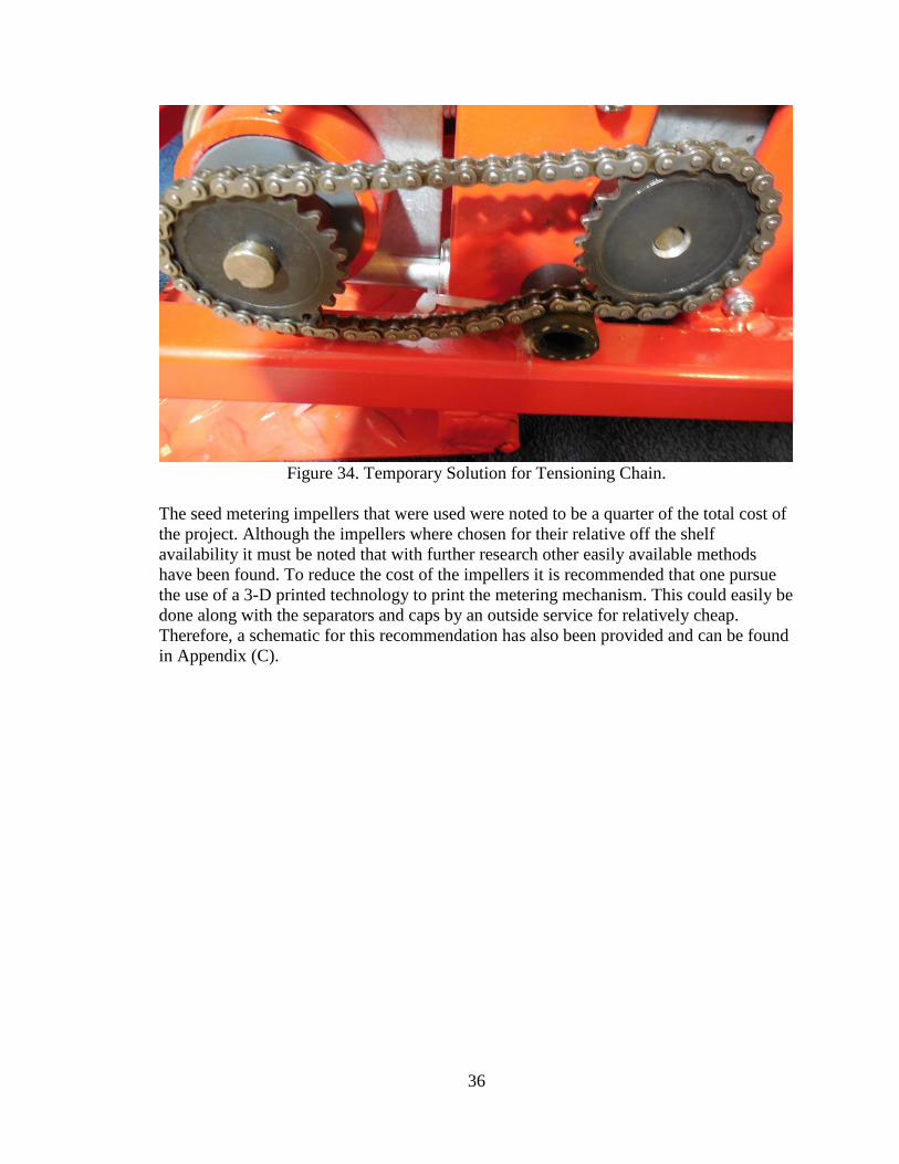
36
Figure 34. Temporary Solution for Tensioning Chain.
The seed metering impellers that were used were noted to be a quarter of the total cost of
the project. Although the impellers where chosen for their relative off the shelf
availability it must be noted that with further research other easily available methods
have been found. To reduce the cost of the impellers it is recommended that one pursue
the use of a 3-D printed technology to print the metering mechanism. This could easily be
done along with the separators and caps by an outside service for relatively cheap.
Therefore, a schematic for this recommendation has also been provided and can be found
in Appendix (C).

37
REFERENCES
1. ASCE. 2006. Sedimentation Engineering. Reston, Virginia; American Society of
Civil Engineers.
2. Balewagons. 2011. Web. 17 Nov. 2011. Available at:
http://balewagons.com/ads/58-john-deere-8300-grain-drill-w-press-wheels
3. Beasley, R.P., Gregory, James, and McCarty, Thomas. 1984. Erosion and
Sediment Pollution Control. 2nd
ed. Ames, Iowa; Iowa State University Press.
4. Brown E (2003). Sowing seeds for the agricultural revolution: Jethro Tull.
Implement & Tractor, 13, 1674–1741
5. Central Coast Water Board. Sediment Management Practices. 2010.
6. Clark, Andy. 2007. Managing Cover Crops Profitably.3rd
ed. College Park, MD;
SARE
7. Frankana. N.p., n.d. Web. <https://reseller.frankana.de/Electric-|-
Multimedia/Power-supply/Adapter/Sockets-and-connectors-33004-EN-
FRA;jsessionid=B741D1C797433D91A3682325B9A578C8>.
8. Goldman, J. Steven, Jackson, Katherine, Bursztynsky, Taras. 1986. Erosion and
Sediment Control Handbook. Halliday Lithography.
9. Holtz, Andrew. Personal interview. 20 Feb. 2013.
10. Kornecki, T. S., Price, A. J., Arriaga, F. J., Balkcom, K. S.. 2010. Effects of
Various Residue Management Systems on Cotton Establishment and Yield in
High-Residue. St. Joseph, Mich.: ASABE
11. Maleki, M. R., Mouazen, A. M., Baerdemaeker, J., Jafari, J. F., & Raufat, M. H.
(2006). Evaluation of Seed Distribution Uniformity of a Multi-flight Auger as a
Grain Drill Metering Device [electronic resource]. Biosystems Engineering, 94(4),
535-543.
12. Massey Ferguson. 2014. Web 18 Feb. 2014. Available at:
http://www.masseyferguson.us/products/seeding-tillage/2433-chisel-plow/
13. Pacific Ag Wholesalers, Inc.. 2014. Web. 18 Feb. 2014. Available at:
http://www.pawline.com/products/FERTILIZER%20SHANKS@@2c%20KNIV
ES%20AND%20COMPONENTS/FERTILIZER%20INJECTION%20KNIVES/
BACK%20SWEPT.aspx
14. Peterson, C.L., E. A. Dowding, K. N. Hawdey, and R. W. Harder. 1982. The
Chisel-Planter Minimum Tillage System. ASAE Paper No. 78-1015, St. Joseph,
Mich.: ASAE
15. R.A. Cooke, T.A. Dillaha, T.M. Gridley, and S. Mistaghimi. 1994. Effectiveness
of different approaches for controlling sediment and nutrient losses from eroded
land. Journal of Soil and Water Conservation 49(6): 615
16. Smith, Richard, Cahn, Michael, Heinrich, Aaron, Farrara, Barry. 2011. Web. 28
October 2011. Low Residue Cover Crop Trial- Follow-up Details Irrigation and
Nutrient Management Meeting. Monterey, Cal.: Universitiy of California

38
Cooperative Extension. Available at:
http://ucanr.org/sites/uccemontereycounty/files/85662.pdf Accessed 21 October
2011.
17. Solex. 2011. Web. 17 November 2011. Available at:
http://www.solexcorp.com/productfiles/herd/750.html
18. Srivastava, A. K., Goering, C. E, Rohbach, R. P, and Buckmaster, D. R. 2006.
Crop Planting. Chapter 9 in Engineering Principles of Agriculture Machines, 2nd
ed., 231-268. St. Joseph, Michigan: ASABE.
19. Stoss, Kenneth J., Joachim Sobotzik, Bin Shi, and Edwin R. Kreis. 2013. Reading
"Tractor Power for Implement Operation—Mechanical, Hydraulic, and Electrical:
An Overview." Agricultural Equipment Technology Conference. Kansas City.:
ASABE

39
APPENDICES

40
APPENDIX A:
ASM CONTRACT & HOW PROJECT MEETS REQUIREMENTS FOR THE
ASM MAJOR

41
ASM Project Requirements
The ASM senior project must include a problem solving experience that incorporates the
application of technology and the organizational skills of business and management, and
quantitative, analytical problem solving. This project addresses these issues as follows.
Application of Agricultural Technology:
The project involves the application of CAD software for the design of a machine to
address a problem. In addition, the project required understanding and application of
mechanical systems and power transmission.
Application of Business and/ or Management Skills:
The project involved business/management skills in the understanding of problematic
economics of planting a low-residue cover crop by hand. With the same skills and with
the aid of cost and productivity analyses, labor considerations, etc. a solution was devised
that solves the previously stated issue of the economics of planting a low residue cover
crop.
Quantitative, Analytical Problem Solving:
Quantitative problem solving techniques included the testing and resultant analysis of the
operation of seeder parameters such as output per revolution and distribution of output
from seeder.
Capstone Project Experience:
The ASM senior project must incorporate knowledge and skills acquired in earlier
coursework (Major, Support and/or GE courses). This project incorporates knowledge/
skills from these key courses.
BRAE 129 Laboratory Skills and Safety
BRAE 133 Engineering Design Graphics
BRAE 141 Agricultural Machinery Safety
BRAE 151 CAD for Agricultural Engineering
BRAE 152 3-D Solids Modeling
BRAE 203 Agricultural Systems Analysis
BRAE 301 Hydraulic/ Mechanical Power Systems
BRAE 324 Principles Agricultural Electrification
BRAE 343 Mechanical Systems Analysis
BRAE 418 and 419 Agricultural Systems Management
AGB 212 Agricultural Economics
VGSC 230 Intro to Vegetable Science
WELD 1TR Welding and Material Forming
ENGL 148 Reasoning, Argumentation, and Professional Writing

42
ASM Approach:
Agriculture Systems Management involves the development of solutions to
technological, business or management problems associated with agricultural or related
industries. A systems approach, interdisciplinary experience, and agricultural training in
specialized areas are common features of this type of problem solving. This project
addresses these issues as follows.
Systems Approach:
A solution to the problem of Ag Sediment Control will be the use of a custom made
seeder which will be capable of applying a cover crop seed to the furrows of vegetable
crop beds.
Interdisciplinary Features:
This project will incorporate Ag Business knowledge by understanding the cost
effectiveness of running and having such a machine. However this project will also
require the use of general engineering knowledge acquired through BRAE to develop the
custom seeder.
Specialized Agricultural Knowledge:
This project entails specialty knowledge in vegetable production, cover crops, and soil
science. In addition, various fabrication techniques and general availability to the
common farm shop.

43
C a l i f o rn i a P o l y t ec h n i c S t a t e U n i ve rs i t y 11/1/2011
BioResource and Agricultural Engineering Department Bennett, Chandler
ASM Senior Project Contract 20150264169128 ASM
Agriculture Sediment Control
Background Information
Growers in the Salinas Valley have been attempting to meet higher produce demands by having
higher turnover rates of their crops, meaning once one is grown another is hastily put into the
ground. However when growers set up vegetable beds in the fall to overwinter and thus be
planted after the last spring frost the beds are prone to erosion. The sediment from the beds
quickly accumulates and becomes sediment runoff which will result in serious fines to growers.
Thus for my senior project I would like to create a solution which will overcome such runoff
from the raised beds. My current proposal is to create a mechanically applied biological filter to
be a barrier of the runoff; such control will be set up in the furrow of the beds as they are shaped.
Statement of Work
This project will entail the creating of a mechanical system to apply a biological barrier to the
furrow of vegetable beds to control sediment. This will also require the evaluation of cover crops
and the cost analysis of the use of the proposed machine.
How Project Meets Requirements for the ASM Major
ASM Project Requirements - The ASM senior project must include a problem solving experience that
incorporates the application of technology and the organizational skills of business and management, and quantitative, analytical problem solving.
Application of agricultural technology
This project will incorporate the use of various mechanical systems such as power transmission, seed transfer, and various fabrication skills. In addition it will entail the use of computer aided design.
Application of business and/or management skills
The project will require the application of machinery management, cost analysis, soil science, and various ag business knowledge.
Quantitative, analytical problem solving
Will require the ability to overcome the problem of controlling agriculture sediment to meet new regulations while balancing the costs associated with such control.
Capstone Project Experience - The ASM senior project must incorporate knowledge and skills
acquired in earlier coursework (Major, Support and/or GE courses).
Incorporates knowledge/skills from earlier coursework
This project will incorporate the following classes: Vegetable science, Machinery management, computer aided design, soil science, various ag business courses, and welding.

44
ASM Approach - Agricultural Systems Management involves the development of solutions to
technological, business or management problems associated with agricultural or related industries. A systems approach, interdisciplinary experience, and agricultural training in specialized areas are common features of this type of problem solving. (insert N/A for any area not applicable to this project)
Systems approach A solution to the problem of Ag Sediment Control will be the use of a custom made seeder which will be capable of applying a cover crop seed to the furrows of vegetable crop beds.
Interdisciplinary features This project will incorporate Ag Business knowledge by understanding the cost effectiveness of running and having such a machine. However this project will also require the use of general engineering knowledge acquired through BRAE to develop the custom seeder.
Specialized agricultural knowledge
This project will require specialty knowledge in vegetable production, cover crops, and soil science.
Project Parameters
1. Must be compact and no more than 100 lbs.
2. Must be able to attach to various tillage equipment ie:lister, bed shaper
3. Easy to set up and operate
4. Ability to change output rate
5. Have enough capacity to plant a minimum of five acres before refill
List of Tasks and Time Estimate
TASK
Research
Design
Material Acquisition
Construction
Testing & Analysis
Adjustments to Seeder
Testing & Analysis
Write Report & Poster Creation
TOTAL
Hours
16
24
12
80
10
5
5
20
___172___
Financial Responsibility
Will be upon the student.
Final Report Due: N/A Number of Copies: 3
Approval Signatures Date
Student:

45
Proj. Supervisor:
Department Head:

46
APPENDIX B:
Cost Breakdown

47
Per Unit Cost Approximation
Quantity Unit Description Price Ea. Amount Part # Aquired From
6.8 ft. 1''x1''x.120'' sq. tubing 1.92$ 13.06$ n/a Steel Supply
3.54 ft. 1/4''x2''x2'' Angle 1.15$ 4.07$ n/a Steel Supply
1.25 ft. 1/8''x3/4'' Bar Flat 0.86$ 1.08$ n/a Steel Supply
1 n/a Steel Tread Plate approx. 2'x1.5' scrap $25 25.00$ n/a Steel Supply
1 ea. SPST16A/125VAC Illuminated On/Off Rocker Switch 4.49$ 4.49$ 275-021 Radioshack
1 ea. Plastic Project Enclosure 6''x3''x2'' 4.99$ 4.99$ 270-1805 Radioshack
1 ea. Misc. wire, connectors, shrink tubing, etc. estimated 10.00$ 10.00$ n/a
2 ea. Clamping U-Bolt, Zinc Plated Steel, 3/8''-16 thread, for 2.5'' OD 2.76$ 5.52$ 3042T33 McMaster-Carr
1 ea. Compact DC Gearmotor, 12 VDC, 25 RPM 37.42$ 37.42$ 6409K17 McMaster-Carr
1 ft. Chemical Resistant PVC (Type I) Rod, 2'' Dia. 8.71$ 8.71$ 8745K26 McMaster-Carr
1 ea. Fully Keyed 1045 Steel Drive Shaft,1/2'' OD, 1/8'' Key, 18'' Long 14.50$ 14.50$ 1497K953 McMaster-Carr
1 ea. Steel Finished-Bore Roller Chain Sprocket, #25 chain, 1/4'' pitch, 23 teeth, 1/2'' bore 10.56$ 10.56$ 2737T153 McMaster-Carr
1 ea. Steel Finished-Bore Roller Chain Sprocket, #25 chain, 1/4'' pitch, 23 teeth, 1/4'' bore 10.56$ 10.56$ 2737T151 McMaster-Carr
1 ea. Standard ANSI Roller Chain, #25, Single Strand, 1/4'' pitch, Rollerless, 4' Long 5.60$ 5.60$ 6261K171 McMaster-Carr
1 ea. Add-and-Connect Link for #25, Standard ANSI Roller Chain 2.00$ 2.00$ 6261K105 McMaster-Carr
2 ea. Unfinished Steel Surface Mount Hinge w/o holes, 3''H, 2''W, .090'' thickness 3.38$ 6.76$ 16175A19 McMaster-Carr
4 ea. 1/4''-20 1/2'' eye 1 1/2'' Zinc Plated Eye Bolt 3.14$ 12.56$ 9489T18 McMaster-Carr
5 ft. Chain 1/0, 0.18'' dia., 0.32'' Wd., 1.25'' Lg., Work Load Limit 440 lbs. 1.59$ 7.95$ 3593T43 McMaster-Carr
2 ea. Thread Oval Connector, Standard Opening, Zinc plated, 3/16'' Dia., 1/4'' opening. 1.43$ 2.86$ 8947T15 McMaster-Carr
10 ft. Chain 1/0, 0.12'' dia., 0.43'' Wd., 0.57'' Lg., Work Load Limit 265 lbs. 0.93$ 9.30$ 3600T36 McMaster-Carr
2 ea. S-Hook w/ Latch, 3/16" dia., Stainless 2.63$ 5.26$ 6043T4 McMaster-Carr
3 ea. Impeller for Kohler 250872 31.16$ 93.48$ 23-2003 iboats.com
1 ea. Five Gallon Bucket 2.78$ 2.78$ n/a Home Depot
1 ea. Five Gallon Bucket Lid 1.28$ 1.28$ n/a Home Depot
1 pack Lock Nut Nylon Zinc #8-32, pack of four 1.18$ 1.18$ n/a Home Depot
3 ea. Painters Tough 2X Gloss Apple Red Spray Paint 3.87$ 11.61$ n/a Home Depot
2 ea. Stops Rust White Clean Metal Primer Spray Paint 3.76$ 7.52$ n/a Home Depot
1 ea. 1'' PVC Coupling 0.25$ 0.25$ n/a Home Depot
1 ea. 2' stick of 1'' PVC Schedule 40 1.24$ 1.24$ n/a Home Depot
1 ea. Machine Screw Round Head, Zinc, #8-31, pack of four 1.18$ 1.18$ n/a Home Depot
4 ea. 1/4'' x 3/8'' Socket Set Screw, Stainless, pack of two 0.92$ 3.68$ n/a Home Depot
1 ea. 12V-40V 10A Pulse Width Modulator DC Motor Speed Control Switch 5.99$ 5.99$ n/a
1 ea. 1/4''x36'' Rod Threaded, Stainless 8.99$ 8.99$ n/a Ace Hardware
2 ea. 1/4'' Wing Nut, Zinc 0.14$ 0.28$ n/a Ace Hardware
6 ea. 1/4'' Washer, Zinc 0.09$ 0.54$ n/a Ace Hardware
8 ea. 1/4'' Nut, Zinc 0.09$ 0.72$ n/a Ace Hardware
4 ea. 1/4' x 1'' Zinc Bolts 0.12$ 0.48$ n/a Ace Hardware
Total 343.44$
ebay.com
Misc.

48
Overall Cost of Materials Purchased
Quantity Unit Description Price Ea. Amount Part # Aquired From
16 ft. 1''x1''x.120'' sq. tubing 1.92$ 30.72$ n/a Steel Supply
25 ft. 1/4''x2''x2'' Angle 1.15$ 28.75$ n/a Steel Supply
3 ft. 1/8''x3/4'' Bar Flat 0.86$ 2.58$ n/a Steel Supply
1 n/a Steel Tread Plate approx. 2'x1.5' scrap $25 25.00$ n/a Steel Supply
1 ea. SPST16A/125VAC Illuminated On/Off Rocker Switch 4.49$ 4.49$ 275-021 Radioshack
1 ea. Plastic Project Enclosure 6''x3''x2'' 4.99$ 4.99$ 270-1805 Radioshack
1 ea. Misc. wire, connectors, shrink tubing, etc. estimated 10.00$ 10.00$ n/a
2 ea. Clamping U-Bolt, Zinc Plated Steel, 3/8''-16 thread, for 2.5'' OD 2.76$ 5.52$ 3042T33 McMaster-Carr
1 ea. Compact DC Gearmotor, 12 VDC, 25 RPM 37.42$ 37.42$ 6409K17 McMaster-Carr
2 ft. Chemical Resistant PVC (Type I) Rod, 2'' Dia. 8.71$ 17.42$ 8745K26 McMaster-Carr
1 ea. Fully Keyed 1045 Steel Drive Shaft,1/2'' OD, 1/8'' Key, 18'' Long 21.70$ 21.70$ 1497K953 McMaster-Carr
1 ea. Steel Finished-Bore Roller Chain Sprocket, #25 chain, 1/4'' pitch, 23 teeth, 1/2'' bore 10.56$ 10.56$ 2737T153 McMaster-Carr
1 ea. Steel Finished-Bore Roller Chain Sprocket, #25 chain, 1/4'' pitch, 23 teeth, 1/4'' bore 10.56$ 10.56$ 2737T151 McMaster-Carr
1 ea. Standard ANSI Roller Chain, #25, Single Strand, 1/4'' pitch, Rollerless, 4' Long 14.92$ 14.92$ 6261K171 McMaster-Carr
1 ea. Add-and-Connect Link for #25, Standard ANSI Roller Chain 2.00$ 2.00$ 6261K105 McMaster-Carr
2 ea. Unfinished Steel Surface Mount Hinge w/o holes, 3''H, 2''W, .090'' thickness 3.38$ 6.76$ 16175A19 McMaster-Carr
4 ea. 1/4''-20 1/2'' eye 1 1/2'' Zinc Plated Eye Bolt 3.14$ 12.56$ 9489T18 McMaster-Carr
5 ft. Chain 1/0, 0.18'' dia., 0.32'' Wd., 1.25'' Lg., Work Load Limit 440 lbs. 1.59$ 7.95$ 3593T43 McMaster-Carr
2 ea. Thread Oval Connector, Standard Opening, Zinc plated, 3/16'' Dia., 1/4'' opening. 1.43$ 2.86$ 8947T15 McMaster-Carr
10 ft. Chain 1/0, 0.12'' dia., 0.43'' Wd., 0.57'' Lg., Work Load Limit 265 lbs. 0.93$ 9.30$ 3600T36 McMaster-Carr
2 ea. S-Hook w/ Latch, 3/16" dia., Stainless 2.63$ 5.26$ 6043T4 McMaster-Carr
3 ea. Impeller for Kohler 250872 31.16$ 93.48$ 23-2003 iboats.com
1 ea. Five Gallon Bucket 2.78$ 2.78$ n/a Home Depot
1 ea. Five Gallon Bucket Lid 1.28$ 1.28$ n/a Home Depot
1 pack Lock Nut Nylon Zinc #8-32, pack of four 1.18$ 1.18$ n/a Home Depot
3 ea. Painters Tough 2X Gloss Apple Red Spray Paint 3.87$ 11.61$ n/a Home Depot
2 ea. Stops Rust White Clean Metal Primer Spray Paint 3.76$ 7.52$ n/a Home Depot
1 ea. 1'' PVC Coupling 0.25$ 0.25$ n/a Home Depot
1 ea. 2' stick of 1'' PVC Schedule 40 1.24$ 1.24$ n/a Home Depot
1 ea. Machine Screw Round Head, Zinc, #8-31, pack of four 1.18$ 1.18$ n/a Home Depot
4 ea. 1/4'' x 3/8'' Socket Set Screw, Stainless, pack of two 0.92$ 3.68$ n/a Home Depot
1 ea. 12V-40V 10A Pulse Width Modulator DC Motor Speed Control Switch 5.99$ 5.99$ n/a
1 ea. 1/4''x36'' Rod Threaded, Stainless 8.99$ 8.99$ n/a Ace Hardware
2 ea. 1/4'' Wing Nut, Zinc 0.14$ 0.28$ n/a Ace Hardware
6 ea. 1/4'' Washer, Zinc 0.09$ 0.54$ n/a Ace Hardware
8 ea. 1/4'' Nut, Zinc 0.09$ 0.72$ n/a Ace Hardware
4 ea. 1/4' x 1'' Zinc Bolts 0.12$ 0.48$ n/a Ace Hardware
Total 412.52$
Misc.
ebay.com

49
APPENDIX C:
Drawings
50
Main Frame Drawing
51
Hopper Frame Drawing
52
PVC Metering Tube Drawing
53
End Cap(s) and Seperator(s) Drawing

54
Alternative Impeller to be 3D Printed Drawing

55
APPENDIX E: Data Collected from Testing
56
Data Collected from Output in Relation to Speed
Speed Ounces/Minute
1 7.4
2 13.1
3 18.8
4 26.3
5 33.3
6 37.9
7 43
8 50.1
9 52.6

57
Data Collected from Output Distribution from Scatter Plate
Location Ounces/ Minute.
A 0.4
B 1.1
C 2.5
D 2.9
E 2.4
F 2.7 Center
G 2.5
H 2.8
I 2.4
J 1.3
K 0.3