the designer’s gallery platformmedia.designersgallerysoftware.com/docs/ewwinmanual1148.pdfthe...
TRANSCRIPT

Copyright © 2015 BriTon Leap, Inc.
All Trademarks are the property of their respective owners.
THE DESIGNER’S GALLERY PLATFORM
USER GUIDE


TABLE OF CONTENTS
Welcome ............................................................................................................................................................................................... 1
EmbroideryWorks Everyday Features ................................................................................................................ 1
EmbroideryWorks Advanced Components (additional features) ............................................................ 2
More About the Fonts ................................................................................................................................................. 2
Installation ........................................................................................................................................................................................... 4
Adding a Feature / Product ........................................................................................................................................................... 5
Overview ............................................................................................................................................................................................... 5
The Library Window ................................................................................................................................................... 6
The Stitch Files Window............................................................................................................................................ 6
Design Pages .................................................................................................................................................................. 7
Designs ............................................................................................................................................................................. 8
Objects .............................................................................................................................................................................. 8
The Windows Docking Pane Interface ................................................................................................................. 8
Files ................................................................................................................................................................................... 9
Saving ............................................................................................................................................................................. 10
Open vs. Merge ............................................................................................................................................................ 10
Zooming ......................................................................................................................................................................... 11
Magnify .......................................................................................................................................................................... 11
Measure Size and Counts (Stitches and Colors) ............................................................................................. 12
Viewing in 3D .............................................................................................................................................................. 12
Background and Grid ................................................................................................................................................ 13
Hoops .............................................................................................................................................................................. 14
Display Calibration .................................................................................................................................................... 15
The Mouse Wheel ....................................................................................................................................................... 15
Ghost Mode ................................................................................................................................................................... 16
Panning and Scrolling............................................................................................................................................... 16
Selection ........................................................................................................................................................................ 17
Status Bar ...................................................................................................................................................................... 17
Navigation .......................................................................................................................................................................................... 18
Objects View ...................................................................................................................................................................................... 20
Auto-Scroll .................................................................................................................................................................... 20
Selecting ........................................................................................................................................................................ 20
Reverse Selection ..................................................................................................................................................... 20
Selecting by Color ..................................................................................................................................................... 21
Locking ........................................................................................................................................................................... 21
Sequencing ................................................................................................................................................................... 21
The Property Sheet ......................................................................................................................................................................... 22
Color ..................................................................................................................................................................................................... 23
Thread Brand and Color .......................................................................................................................................... 24
Coloring Letters .......................................................................................................................................................... 26
Color Sorting ................................................................................................................................................................ 27

Designer’s Gallery Platform
Deleting Stitches by Deleting a Color ................................................................................................................. 28
Applique .............................................................................................................................................................................................. 29
Material .......................................................................................................................................................................... 29
Position .......................................................................................................................................................................... 29
Important Notes: ........................................................................................................................................................ 31
Preferences ................................................................................................................................................................... 31
The Thread Editor ........................................................................................................................................................................... 32
Transform Controls ........................................................................................................................................................................ 34
Mirror and Rotate ...................................................................................................................................................... 35
Centering In the Hoop .............................................................................................................................................. 35
Fit to Hoop .................................................................................................................................................................... 35
Remove Hidden Stitches ......................................................................................................................................... 35
Size and Move .............................................................................................................................................................. 35
Align and Distribute .................................................................................................................................................. 37
Mirror X4 ....................................................................................................................................................................... 38
Scatter............................................................................................................................................................................. 39
Instant Repeat (Advanced) .................................................................................................................................... 39
Precise Position (Advanced) ................................................................................................................................. 40
Carousel (Advanced) ................................................................................................................................................ 42
Stitch Files .......................................................................................................................................................................................... 43
The Sweep ..................................................................................................................................................................... 44
Stitch Properties ......................................................................................................................................................... 45
Stitch Properties (Advanced) ................................................................................................................................ 46
Project Advisor ................................................................................................................................................................................. 47
StitchPerfect (Advanced) ........................................................................................................................................ 47
Other Utilities .................................................................................................................................................................................... 48
Add Knockdown Stitching Utility ........................................................................................................................ 48
Save Image .................................................................................................................................................................... 48
Other Preferences ........................................................................................................................................................................... 49
Embroidery Hoops .................................................................................................................................................... 49
File Conversion ........................................................................................................................................................... 51
Preferred Stitch Format .......................................................................................................................................... 52
Removing Overlaps Preference ............................................................................................................................ 52
Auto Recover ............................................................................................................................................................... 52
Checking For Updates .............................................................................................................................................. 52
Sizing of Design Files (Advanced) ............................................................................................................................................. 53
Lettering.............................................................................................................................................................................................. 54
Monograms vs. Letters ............................................................................................................................................. 54
Selecting Letter Type ................................................................................................................................................ 54
Customize the Design ............................................................................................................................................... 56
Monogram Font and Quick Style .......................................................................................................................... 57
Font Selection .............................................................................................................................................................. 57
Slant and Space ........................................................................................................................................................... 57

Enveloping .................................................................................................................................................................... 57
Changing the Color of one Letter ......................................................................................................................... 58
Monogram Sewing Order ........................................................................................................................................ 59
Stitch Properties ......................................................................................................................................................... 59
Towels ............................................................................................................................................................................ 60
Bedding .......................................................................................................................................................................... 60
Garments ....................................................................................................................................................................... 61
The Library ........................................................................................................................................................................................ 62
The AccuQuilt Libraries ................................................................................................................................................................ 63
Applique Properties Tab ......................................................................................................................................... 64
Multi-Position Hooping ................................................................................................................................................................. 65
Sewing ............................................................................................................................................................................ 66
Multiple Hooping ....................................................................................................................................................... 66
Output Files .................................................................................................................................................................. 67
Region Naming: .......................................................................................................................................................... 68
Getting Results ............................................................................................................................................................ 68
Stitch Simulator ................................................................................................................................................................................ 69
The Density Map .............................................................................................................................................................................. 70
Basting functions ............................................................................................................................................................................. 71
Printing ................................................................................................................................................................................................ 72
Editing the Hoops (Advanced) ................................................................................................................................................... 74
Split Into Hoop (Advanced) ................................................................................................................................... 76
Importing Fonts (Advanced) ...................................................................................................................................................... 77
Mapping Letters ......................................................................................................................................................... 78
Adjusting Baseline ..................................................................................................................................................... 79
Spacing ........................................................................................................................................................................... 79
Editing Fonts Already Imported .......................................................................................................................... 79
Using Imported Fonts ............................................................................................................................................... 80
Deleting A Font ........................................................................................................................................................... 80
Stitch Editing (Advanced) ............................................................................................................................................................ 81
Selecting Stitches ....................................................................................................................................................... 81
Splitting a design ........................................................................................................................................................ 82
Insert Stitches .............................................................................................................................................................. 82
Converting Stitches ................................................................................................................................................... 83
Adding compensation .............................................................................................................................................. 83
Stitch-Edit Keyboard Shortcuts ............................................................................................................................ 84
Designer’s Gallery Creator™ ..................................................................................................................................................... 85
Welcome to Creator! ................................................................................................................................................. 85
The Interface ................................................................................................................................................................ 88
Working with Images ............................................................................................................................................... 95
Object Basics ................................................................................................................................................................ 98
Working with Objects ............................................................................................................................................... 99
Editing Outlines ....................................................................................................................................................... 106

Designer’s Gallery Platform
Working with Outlines .......................................................................................................................................... 109
Entry and Exit ........................................................................................................................................................... 110
Magic Wand ............................................................................................................................................................... 112
Cut/Copy/Paste Operations ............................................................................................................................... 114
Grouping Objects ..................................................................................................................................................... 115
Sequencing ................................................................................................................................................................ 115
Ties and Transits ..................................................................................................................................................... 118
Default Style .............................................................................................................................................................. 119
Line Objects ............................................................................................................................................................... 119
Manual Objects ......................................................................................................................................................... 119
Run Objects ............................................................................................................................................................... 120
Motif Run Objects .................................................................................................................................................... 121
Satin Border Objects .............................................................................................................................................. 122
Satin Column Objects ............................................................................................................................................. 123
Satin Column Input (Level 2) ............................................................................................................................. 126
Satin Column Cornering (Level 2) .................................................................................................................... 131
Satin Column Joining (Level 2) .......................................................................................................................... 132
Fill Objects ................................................................................................................................................................. 135
Freestanding (Lace) Objects ............................................................................................................................... 139
Motif Fill Objects ..................................................................................................................................................... 139
Applique Objects ..................................................................................................................................................... 140
Stippling Objects ..................................................................................................................................................... 142
Cross Stitch Objects ................................................................................................................................................ 143
Contour Echo Objects (Level 2) ......................................................................................................................... 144
Program Motif Objects (Level 2 & 3) ............................................................................................................... 144
Converting Stitch Types ....................................................................................................................................... 145
Lettering Templates .................................................................................................................................................................... 146
Keyboard Shortcuts ............................................................................................................................................... 148
Creator Level 3 .............................................................................................................................................................................. 149
Carving lines ............................................................................................................................................................. 150
Using Styles ............................................................................................................................................................... 150
Stylesheets ................................................................................................................................................................. 153
Path Operations ....................................................................................................................................................... 156
Inflating / Deflating shapes ................................................................................................................................. 159
Automatic Outlining ............................................................................................................................................... 159
Publishing .................................................................................................................................................................. 162
Exporting Vector Art .............................................................................................................................................. 165
Correcting Sewing Issues .......................................................................................................................................................... 166
Help .................................................................................................................................................................................................... 171

Welcome
1
WELCOME
Hello and welcome to The Designer’s Gallery Platform! Thanks for reading this User Guide! Since you’re here, let us tell you some things about this exciting program because this represents a giant step forward in machine embroidery. It requires no hardware dongle and can be installed on multiple systems requir-ing only your personal serial number to be typed in for the program to run. Once you enter a serial num-ber, you can register the program, which provides several benefits. One of those benefits is that if you should ever lose your serial number, we can recover it for you.
This manual covers the features in the program for EmbroideryWorks Everyday and Advanced as well as Designer’s Gallery Creator. The idea behind Everyday is to include the features, which are essential for every embroiderer, yet not to overwhelm the user with unnecessary extras. It is designed to be simple and easy, yet powerful enough to accommodate the person who wants to do more than simply using ex-isting designs.
The EmbroideryWorks version Advanced adds some very useful tools and settings which make life easier for a user who has some experience with embroidery. If you’re new to embroidery and have purchased Advanced, please don’t worry; these features will not get in your way. They are easy and fun! And once mastered, will provide valuable assistance with your embroidery projects.
EmbroideryWorks Everyday Features
• 12 Fonts for multi-line text, monogramming and circle text.
• Sample designs which are scalable and recalculate their stitches as you interactively transform them.
• Unlimited lines of letters or monograms and embroidery designs can be combined.
• The Project Advisor which helps you with stabilizer, needle and other advice for your project.
• The Sweep Tool which reduces stitch count, time and puckering.
• You can mix and match fonts and sizes.
• Merge existing embroidery files into your design.
• Use your Designer’s Gallery Studio catalog for easy access to your designs and cataloging.
• Our patented Density Map to evaluate designs without needing to sew them.
• If you overlap designs, Everyday will remove the overlapped stitches so the design will sew perfectly.
• Browse and Merge designs in folders and from inside .ZIP files.
• Resize existing embroidery files with stitch recalculation. You can resize embroidery within everyday up
to 250% and down to 50%.
• Adjust density of designs, including separate adjustments for Satin and Fills, per color
• Automatically split designs into our pre-defined Multi-Position Hoops.
• Colorize any embroidery design. You can change the colors one at a time, or convert the entire design or
any selected part of it to your preferred thread brand with just a few mouse clicks.
• Simulate the sewing of any design. The simulator can play in 3D, a play forward and backward, and has
variable speed. The simulator also has a slider so that you can manually scroll forward and backward
through the design to any point without waiting. You can even insert a color stop in the sewing process.
• Convert any design from one format to any of the supported types, which include:
• Read: ART, CND, CSD, DST, DSZ, EMD, EXP, EXP+, GNC, HUS, JAN, JEF, JEF+, PCM, PCS, PEC,
PES, PHC, SEW, SHV, TAP, VIP, VP3, XXX, EMB.
• Write: CSD, DST, DSZ, EXP, EXP+, HUS, JEF, PCS, PES (v1-9), PCM, SEW, SHV, TAP, VIP, VP3.
• Designer 1 Disk utiltiy for floppy and USB machines.

Designer’s Gallery Platform
2
• Create a working file (.BE extension) to save your design as an editable and merge-able file. Your work-
ing file is saved for you automatically when you save a stitch file so you don’t have to ‘Save’ twice every
time you make some changes—once for the stitch file and once for the working file.
• Real Scale zooming allows you to view your designs on screen at the actual size that they will stitch out.
• Navigation Window that provides instant control over the zoom and scroll in the program’s view.
• Sewing Order control allows you to re-sequence the designs to sew in the order you want them to sew.
• Color Sorting control to intelligently reduce the number of extra color changes.
• Adjustable Mouse Wheel attribute for Zoom or Scroll.
• Simple centering in the hoop plus advanced alignment.
• Thread Palette creation and thread inventory system.
• Basting designs.
• Create Applique cut files for most cutters.
• Display and print cropped photo as applique – eliminate cutting in the hoop!
• Add knockdown stitching for sewing on towels
• Automatically check for updates.
EmbroideryWorks Advanced Components (additional features)
• 32 additional fonts for multi-line text, monogramming and circle text.
• Import Fonts, a great feature to work with alphabet design packs. The alphabet design packs are easily
mapped into the font list, turning the letters into a keyboard font.
• Stitch Editing, including Split, Insert and Delete, Pull compensate and adjust stitch.
• Custom Multi-Position Hoops.
• Advanced stitch adjustments.
• Extra Library design sets for Appliqué and more. These can be used with your existing designs.
• Our StitchPerfect system, which adjusts the design to better sew on your project.
• Precision tools for design placement.
• Repeat designs for tiling.
• Full featured Thread Chart creation, including metallic and variegated color creation.
• Baste design and hoop.
More About the Fonts
These fonts give you enormous control over them. The specifics vary depending on which lettering style you’re using, but in general, you can adjust the font, color, size, aspect, center, rotation, mirroring, slant, kerning, layout, stagger, sequence, envelope shape, stitching properties including density, underlay, un-derlay density and compensation (which can be used to increase boldness) for the design as a whole. And you can adjust the color, size, position, rotation, kerning, aspect and mirroring down to the individual let-ter. You can adjust the letter sequence for Monograms so that letters may overlap exactly how you want them. And if you do overlap your letters within a Monogram, the hidden stitches are automatically re-moved for you so that the design sews out nice and flat. For fast and easy Monogram setup, you have 14 Quick Styles to layout your design, including Vertical, Square, Oval and Diamond.
When sizing letters, your letters automatically switch to a fill-like satin stitch. This looks like a fill, but un-like a fill, the stitches maintain the beauty of the curved satin column. Another benefit of this is that fonts can be made far larger than ordinary embroidery fonts - some as tall as 8".
To make the fonts even more versatile in size, automatic adjustments are made for you to help the letters sew smaller than they would in other programs. For instance, when you make the letters smaller, narrow satin stitching is automatically adjusted to keep long-enough stitches to actually sew. And although some

Welcome
3
small designs look good on screen, they won’t embroider well. The fonts in the program protect your stitching automatically.
Multi-Line text offers line spacing, and in Circle Text, you can keep on typing, right into a spiral!
And the platform can further be extended by adding font and design packs, including those for Mono-gramWorks, now available from your dealer or online at www.designersgallerysoftware.com.
Welcome to Designer’s Gallery, and let the fun begin!

Designer’s Gallery Platform
4
INSTALLATION
Installation of the platform is easy. First install the disc or download the installer. If you have the disc, XP may automatically run it, but in later versions of Windows, Auto-Run has been turned off by Microsoft, so you’ll have to browse to it using Windows Explorer (a.k.a. “Computer”). Look for the program with “Set-up” in the name and double click on it. This will start the installation. In Windows it looks like this:
Click ‘Next,’ then accept the license agreement by clicking the button, then click ‘Next,’
Click ‘Next.’ You will usually want a desktop icon for ease of running the program. Click ‘Next,’
You are now ready to begin installing. Click ‘Install,’
You can run the platform now, or you can just quit the setup by unchecking the Launch box.
You are finished installing. Please have your serial number(s) ready for the first time you run the program so you can get started right away!

Adding a Feature / Product
5
ADDING A FEATURE / PRODUCT
If you already have the program installed and have purchased an additional product such as Creator or EmbroideryWorks Advanced, you can use the menu ‘Help->Serial numbers…’ to add your new serial number. You do not need to install the program again. Simply type in the serial number and click ‘Set’.
OVERVIEW
Below is a picture of the main window:
• As with most programs at the top of the window is the Main Menu, and below the Main Menu is the
Main Toolbar. These two components are always available and handle the most significant commands of
the program.

Designer’s Gallery Platform
6
• The Tool Pane is a little different. It will display different contents, depending on what type of task you
are performing. For instance, if you are running the Sewing Simulator, the controls for the simulator will
appear in the Tool Pane.
• The Main view displays the current Design Page. A Design Page is a representation of a .BE file, which
can contain multiple embroidery designs, lettering objects and frames.
• More than one Design Page can be open, and these are selectable by using the tabs above the Main View,
just below the Tool Pane. As you save Design Pages, they will take the names you have given them. Un-
til a page is saved, it will be called “Untitled...”
• The Status Bar provides relevant information about what is going on with the program’s current opera-
tion. For instance, if you are measuring items, the text in the bottom right corner of the Status Bar will
update with the measurements created by that tool.
• The Navigation view provides an easy-to-use way to navigate around the current design page, and to con-
trol the zoom for it. This is especially useful when you have a lot of objects on a large design page and
you want to go from one place to another without repeatedly zooming and scrolling.
• The Objects view displays Designs and Objects sequential order as they are opened or merged onto the
design page. Each root (leftmost) item in the Objects view is a Design. A Design or object may be, for
example, a lettering design, or perhaps a regular embroidery design.
• The Designs in the Objects view can have objects within them. To view those objects, click the ‘+’ which
opens up the tree, thereby ‘disclosing’ the objects in the design. With a normal embroidery design
merged into the page, you will be able to see individual colors within the design once you click the ‘+.’
Some designs, like lettering designs, may not disclose their individual objects because all editing is done
via the Properties view.
• The Objects view can also be used to select designs and objects, which is useful when objects within a
design are grouped, such as with regularly merged embroidery designs.
• The Properties view displays information and controls for the currently selected objects and designs. For
example, if a single-color design such as lettering is selected, you will see in the ‘Color’ property page
only the single color for the lettering. If no design or object is selected, the Color property page is shown
and the colors for the entire design page are shown.
The Library Window
The Library window is used to merge designs into the cur-rent Design Page.
Individual design collections will appear on the left. These collections are ones that are included in EmbroideryWorks and MonogramWorks. They are special designs because they will generate their stitches dynamically as you size them, similar to the lettering.
Clicking on a collection icon on the right will result in the designs from that collection to appear on the left. To import a design, select it and click OK. You can also double-click on a design to import it and close the window.
The Stitch Files Window
The Merge Files Window is used to merge existing embroidery files into the current Design Page.

Overview
7
The Browse view on the left side is called a ‘Tree’ control, and it has a ‘Root’ level, which is left-most and ‘branches’ which you can open and close using the ‘+’ and ‘-‘. You will also see individual .ZIP files as branches, so you can import designs directly from within those as well.
On the toolbar, there are controls for thumbnail size and 3D display. The ‘Close’ button will close the window without importing anything.
The “Sel. All” button selects all the designs in the view on the right.
To bring designs in, click ‘Import’.
Note: There are two tabs visible, ‘Browse’ and ‘Catalog’. The catalog tab is used for working with files that have been categorized in Designer’s Gallery Studio. If you do not have a Catalog tab visible, then the pro-gram was not able to find a Studio catalog.
As with most views like it in Windows, the thumbnail view on the right allows single design selection, by clicking on an item. But also you can select a range of designs by first selecting a design then holding the shift key down and clicking another design. Additionally, you can use the control key to click on different designs that are not next to each other, and that will select those too. This is called a disjointed selection.
You can also double-click on a design to import it and close the window.
When the Catalog is available, you can drag files onto keywords in the catalog, the same as you would do in Studio or Studio III. You can also right-click on the catalog keywords to add, edit and change keyword entries. This is the same catalog file as used by your Studio, so any changes you make will be available in both programs.
Design Pages
A Design Page is where designs and lettering can come together to form a composition or a scene. That page is also represented as a single embroidery (or working) file. For example, you may have merged multiple embroidery designs, added a couple lettering designs, and then surrounded them with a Library frame. All those individual designs exist on the Design Page. That scene can be saved as an embroidery file for use in your machine, and it can also be saved as a ‘Working File’ (extension .BE) which allows for editing later. (Suppose you miss-typed some lettering.)

Designer’s Gallery Platform
8
As Design Pages are opened or saved, their name will appear in the Tabs above the Main View. You can switch between Design Pages using the Tab View. This is handy for clipboard operations such as doing a copy and paste between Design Pages.
Designs
Each Design on a Design Page is one of the three types, ‘Embroidery Design,’ ‘Lettering Design’ and ‘Li-brary Design.’ These design types work together to build useful embroidery compositions. The designs are visible on the Design Page in the Main View, and the sequence of the designs is visible in the Objects View.
Designs are collections of objects. For example, a merged embroidery design is a collection of color ob-jects, each of which contains stitches for a single color in the design.
Designs may be ‘Grouped’ which allows you, the user, to select and move the design around in the Main View as a single design. By default, when you merge an embroidery design into the page, it comes in as grouped. If you want to change one or more colors (or objects) in the design, you have some options:
Ungroup the design, which makes each object selectable in the Main View.
Select the object or objects in the Objects View.
Designs as they appear in the Main View may be ‘Locked’ which prevents inadvertent moving or editing. The lock may also be used to hide the design(s). The state of the Lock is set using the Objects View toolbar.
Objects
Each Design on the design page can contain one or more objects, each of which contains colors, stitches and other information. The only objects you will see are individual color objects within a merged em-broidery design. Each object can be moved, edited, deleted, etc.
The Windows Docking Pane Interface
This interface can be configured and the configuration is persistent, i.e. it is remembered between pro-gram invocations. The controls for this interface consist of a Pin, a Close Box and a Tab. The Pin and Tab are related. When the Pin is “unpinned” the window slides into the main window frame and presents a Tab with the window name. When the Pin is “pinned” the window stays open and the Tab goes away.
In the unpinned configuration, hovering the cursor over the Tab reveals the window. When the cursor is moved out of the window it slides back into its unpinned position.
The Close Box dismisses the window altogether. To restore a dismissed window you must use the View Menu->Toolbars and Windows item to restore the dismissed window.
Left: Unpinned Right: Pinned

Overview
9
Left: Pinned Windows. Right: Reset Windows command in Menu.
Files
The platform uses a few different file types, each having its own file extension. For example ‘.BE’ is a working file. This file type contains all the Designs and Objects representing a single Design Page. These designs and objects can be edited, as they have not been forced to become a simple set of stitches, which is what most machine-embroiderable files are.
Licensed files, such as fonts will have .BF and .LF files. These are installed by the installer for our collec-tions. You cannot edit or use these files as a user. The program loads them automatically as needed.
Stitch files, which in the commercial embroidery trade are called ‘expanded’ files such as .PES or .DST are simply collections of stitches, and if you are lucky, colors.

Designer’s Gallery Platform
10
Saving
When you save a Design Page it will ask you to choose which Stitch File type you want to use. For exam-ple a Baby Lock / Brother embroidery machine owner will choose .PES as the stitch file type. In addition, the program will also silently save a working file (.BE) thus saving you the extra step of saving it sepa-rately. As mentioned earlier, the working file allows you to edit your designs including text. If you want to save individual files (not both stitch and working) you have all the options on the File menu.
Open vs. Merge
Files can be ‘opened’ which starts a new Design Page in the Main View so that you can see the open file. Use Open for .BE files.
If you already have a Design Page open, you can ‘merge’ files, which adds the contents of the files to whatever you have on your page currently. To merge a file click on the Merge icon on the Toolbar or go to File/Merge Stitch file or Merge Working fileThe Main View
Design pages are displayed in the Main View of the program. There can be multiple design pages open at any given time. For each page in use, a Tab control is displayed at the top of the Design page. Additional Design pages are added by clicking the New button on the Main tool bar, by pressing Ctrl-N by choosing New Page from the File menu or choosing New from the Window menu:
A design page is activated by clicking its Tab control. Or you can select it from the list in the Window menu.
The Tab control will display the name of the file associated with the page once it has been saved, other-wise it is named “untitled x” where x is a running number.
The Main View has a background, a hoop, and rulers along the side and, naturally, the designs you have placed in the Design Page.

Overview
11
Zooming
Zooming is handy for edits, and this makes the process of zooming more convenient. Also, one of the options in the program is to be able to use a mouse wheel to scroll the design page up and down. If you have this mode on, the zoom slider is another useful tool. Just a reminder, there are also keyboard shortcuts for zooming: ‘z’ zooms in, and ‘Z’ (shift-z) zooms out.
Zooming can also be accomplished with the Zoom Menu and Toolbar con-trols.
• ‘All’ zooms to all objects on the design page.
• ‘Selected’ zooms to selected objects on the page.
• From the Zoom menu specify what should be zoomed: the Hoop, All elements or the Selected element or
choose the amount of zoom.
Tip: Memorize the keyboard shortcuts for the Zooming and Panning; using them can speed your design-ing!
Use the Zoom slider to zoom on the Main view. Up zooms in, down zooms out.
There are zooming keyboard shortcuts:
• ‘z’ to zoom in
• ‘Z’ to zoom out.
• 0 = Fit Hoop
• ‘A’ to zoom all
• ‘S’ to zoom selected
• 1 - 9 will zoom to 100%-900% of real-world scale.
Magnify
The Magnifier on the Main toolbar will let you change the zoom in three ways after you click on it:
• Left-click to zoom in
• Right-click to zoom out
• Drag a rectangle to zoom on just that area. (This will also cancel the tool.)
Note: The Overview or Navigation window can alter the zoom too, and we’ll cover that in its own chapter.

Designer’s Gallery Platform
12
Measure Size and Counts (Stitches and Colors)
The Measure button on the Main toolbar will set the program in a mode, which allows you to measure items in the Main View.
As you drag the cursor, you are measuring the distance you’ve dragged. This distance is displayed on the status bar:
To cancel measuring, click again on the Measure button in the toolbar, or click the Selection Tool (arrow) in the toolbar. Items that are selected also have their size, stitch count and color count shown in the sta-tus bar. If nothing is selected, then the size and counts for the entire Design Page will be shown.
Viewing in 3D
The default setting for the Main View is to display stitches in a realistic 3D, which lets you easily see where the needles will penetrate the fabric. This can be turned off using the ‘3D’ button on the main toolbar.

Overview
13
Background and Grid
You can alter the background of the Main View. Click the Preferences button on the Main toolbar. This will bring up the Program Preferences window, which allows you toset many program and Design Page options. Click on the Grid Settings to adjust them.
To change the background color, click the Color button, which will display a standard color picker:
You can even create your own colors and add them to the custom colors section.
Select a Custom color and click OK to set the new color.
Adjustments:
• The Grid is adjustable too. You can alter the display of gridlines by choosing between lines and dots.
You can also set the spacing of the grid, and that can be set separately for both metric and inch settings.
• The arrow buttons, labeled “>>” and “<<,” will copy the settings from inches to metric and vice versa.
Thus, you can set up a grid that has metric spacing for machine/hoop accuracy, but can display infor-
mation to you in inches.
• Snap-to-Grid will help align objects to the grids as you move them in the Main View. As you move in
one direction (up, down, left, right) the edge of whatever you are moving will ‘stick’ like a magnet to the
grid as you approach a grid line in that direction. If you want to overcome the snap-to-grid, you can pass
the grid and then come back in the reverse direction. (Which means the opposite edge will want to snap
to some other grid.)
• Grids do not force you to stick to them when Snap-to-Grid is on. Rather, it merely enables the snap as
you get close, which may help with precision alignment as you move things around.
• Using the menu or the Grid button on the toolbar, you can turn the Main View display of the grid on and
off.

Designer’s Gallery Platform
14
Hoops
• The hoop that you will view in the Main View is chosen for the Design Page using the Preferences Win-
dow also.
Left: Hoop selection. Right: This is what a hoop looks like in the Main View.
Using this window you can select different hoops, the selected hoop to be shown rotated 90°, add new hoops of your own creation or edit the selected hoop. The ‘Defaults’ button reloads the hoops that are in-stalled with the program. This is useful if you update the program or have previously deleted some de-fault hoops.
Note that when you create a new hoop or modify an existing hoop, that you are really defining the sewing area, or what is known as the sewing field, not the physical dimensions of the hoop. You must know your machine’s embroidery field as you cannot create a hoop that is larger than what your embroidery ma-chine can sew.

Overview
15
Display Calibration
The Main View is calibrated to a real-world scale for precise display of designs. Use the Preferences Win-dow to calibrate your display for real-world size:
Hold a ruler up to your screen and adjust the slider until the measurement in the program matches your real-world ruler. This will help you better estimate real design size while editing designs.
The Mouse Wheel
The Mouse Wheel can zoom the Main View in and out. It can also be used to scroll the page up and down. We recommend that you use the setting that allows for zooming as this is more useful to most users.

Designer’s Gallery Platform
16
Ghost Mode
Ghost Mode is an option relating to how the Main View displays objects when not selected. The idea for Ghost Mode is to make it more obvious which objects are selected by fading out those items that are not selected.
Left: Ghost Mode on. Right: Ghost Mode off.
The intensity of the Ghost Mode can be altered with the Preferences.
Panning and Scrolling
The scroll bars at the right and bottom of the Main View can be used to scroll the view around, which is very useful when you are zoomed in.
There is also a mode that allows you to ‘Pan’ the design, which works like a scroll, but where you move the view by dragging the mouse. Hold the space bar down and drag the mouse to pan the view.
As you drag on the main view, you may come near the edge of the page. This will cause the page to scroll thus enabling you to drag into a position that’s not currently in view.

Overview
17
Selection
One of the most common tasks in the Main view is to select items. Using the Selection Tool (Arrow button on the main toolbar) you can select and move items in the design page. Select items by clicking on them. This will place ‘handles’ and a dotted line around the selected items.
You can also see that items are selected by looking in the Objects view. Another way to select items in the Main view is to drag a rectangle around those items. Anything completely in the rectangle will be select-ed. However, if an object is grouped with something outside the rectangle, it will not be selected.
Status Bar
The status bar is located at the bottom of the program window. Size, stitch count and color count infor-mation appear on the right side of the status bar. If you have no design selected, then the display will con-tain information about the entire design page. If you have something selected, then the information con-tains the word, ‘Selected’ and represents only those selected items.
You can double-click on the size information in the status bar to quickly switch between metric and inch-es on the design page and status bar.
The status bar also has a line of text on the left that can provide additional information about an onscreen control. Hover the mouse over a control, specifically a toolbar button, and the status bar may provide ad-ditional clarification of what the button does.

Designer’s Gallery Platform
18
NAVIGATION
The Navigation H.U.D. (Heads Up Display) is an ingenious device that keeps navigation tools readily available, yet tucked away, for easy access to the entire working area on your Design Page. To access the Navigation H.U.D. (aka: Nav H.U.D.), click the Compass Rose icon at the top of the zoom slider in the upper right hand area of the main view.
The Nav H.U.D. is especially useful when working on large designs and/or a small monitor. It quickly gives you a bird’s eye view of your work area as well as a nice “you are here” indicator. In the following image, the area around his eyes will be centered on the screen.
As you move the cursor, the ‘+’ indicates the area of focus. The panel lets you pan around the design page. The benefit is that you can make edits to different design sections while you are still zoomed in to a com-fortable level.
The Nav H.U.D works in conjunction with the Pan Tool, which is accessible by holding down the spacebar.
Hold the spacebar and drag with this cursor to pan.
Whereas the Pan Tool is useful for moving around the area you are currently working in, the Nav H.U.D. makes it easy to scroll across the entire page to a specific place in one easy step.
The chosen hoop is shown in the Nav H.U.D. whether that hoop is visible or not. This is because the size of your workspace is related to the size of that hoop. The selected hoop is a visual reference only and does

Navigation
19
not prevent you from designing or saving projects larger than the selected hoop or, for that matter, larger than your machine can sew.
Therefore if you have a small hoop selected and a design that well exceeds the hoop boundaries, it is pos-sible that you won’t be able to navigate to the outer reaches of your design. The solution is to select a larger hoop from the Environment > Hoops option in the Program Preferences panel.
Same design with the hoop set to 60mm x 40mm with the cursor shown at the upper left limit. Parts of this design are inaccessible.
Normally, once you’ve panned or zoomed in the Nav H.U.D. the panel will automatically close when you release the mouse. If you’d like to leave the Nav H.U.D. open while you move to several locations, click the ‘Pin’ button just to the left of the close box. Once pinned, the panel will stay open until you click out of it, or click the ‘Close’ button on the top, right in the H.U.D.
Unpinned (default setting) Pinned
Notice on the top of the Nav H.U.D. are three small buttons labeled ‘A,’ ‘S,’ and ‘H.’ These buttons corre-spond to preset zoom settings of ‘All,’ ‘Selected,’ and ‘Hoop,’ whose keyboard shortcuts are respectively ‘A,’ ‘S,’ and ‘0.’
Just below the compass rose icon is a zoom slider. Slide up to zoom in; down to zoom out. Click on the ‘+’ and ‘-’ buttons to zoom in and out also. If you’ve ever used an online map, this zoom slider control should feel familiar. The slider control also responds to numeric key entry. For example, pressing 5 will move the slider control to 500%.

Designer’s Gallery Platform
20
OBJECTS VIEW
The Objects view shows the designs that have been opened or merged on-to the Design Page and objects within those designs.
Notice that the designs are numbered in the Objects view. The designs or objects are numbered in the order that they have been opened or merged onto the design page. In the illustration above lettering was opened onto the Design Page first. So, it has been numbered 1. The following merged design is number 2 in the sequence. When re-sequencing objects the numbers will change accordingly.
Using the Objects view designs may be selected, sequenced and deleted. The Objects view can display individual objects within designs where al-lowed. Stitch files (merged embroidery designs) are one example of a De-sign Type that allows the display of individual objects within the design. Clicking on the ‘+’ at the left of the design will expand that design in the
Objects view. Under that design will then appear the individual objects.
Auto-Scroll
As you drag on the Objects view, you may come near the top or bottom edge. This will cause the view to scroll thus enabling you to drag into a position that’s not currently in view.
Selecting
Using the Objects view you can select any number of Designs or Objects, regardless of whether or not they are locked, hidden or grouped. This allows for editing of objects or designs without ungrouping. For exam-ple, the following design is all grouped so that it can be moved around the page as a single design. However, you may want to select just the second color to change it, re-sequence it or even delete it.
The toolbar on the Objects view also has selection options including ‘Se-lect All’ which is the first button on the left. If the Main view is active you can also type Ctrl-A to select all or you can use the Edit menu for this option too.
Reverse Selection
The second button will reverse the current selection. This means that whatever you have selected will no longer be selected, but everything else will become selected. This is useful when you want to delete eve-rything except for a single design element.

Objects View
21
Range Selection
Using the Objects view you can select multiple designs or objects. If a single object is selected, you can use the shift key while clicking a second object and this will select a range of objects: Everything in between the two will be selected.
Disjointed Selection
If you use the Ctrl key while clicking on objects, you can singly select designs or objects. To de-select an object that’s already selected, Ctrl-click on it. This will reverse its selected state.
Graphical Selection
You can also drag a rectangle around objects in the Objects view to select whatever is in the rectangle.
Note: Dragging enables Auto-Scroll, and your view will move allowing you to select items that weren’t initially visible.
Selecting by Color
If you want to select all objects of a given color, select one of the objects as described above. Then use menu option, Edit->Select by Color. This will find and select all the objects on the page which have those same colors in them. This is a handy feature to change the color of several things at once.
Locking
If you want to prevent designs or objects from being selectable in the Main View, you can ‘Lock’ them. Locking an object does not affect its grouping; it only prevents it from being clicked on. The second but-ton, a white lock with an ‘X’ on it, will not only lock the design or object, but will prevent it from being displayed in the Main View.
To unlock something, click the third lock, which appears as an open lock icon.
Sequencing
The sequence of objects and designs can be changed using the Objects view. One way is to right-click on a selected item which will cause a pop-up menu to be displayed. That menu has options to move items earlier or later in the sequence.
You can also drag and drop items in the tree to re-sequence them. Dropping an item (let’s call it ‘B’) on another (called ‘A’) will place that dropped ‘B’ item right after ‘A’ in the sequence. If you drag an object on-to the design icon, then that drop will be placed at the head of the de-sign.
You can also re-sequence selected designs and objects using the ‘Se-quence Objects’ command on the Edit menu.

Designer’s Gallery Platform
22
THE PROPERTY SHEET
When you have design or object items selected, there may be properties that you can adjust. The Property Sheet contains individual ‘Property Pages’ that let you adjust the selected items. The pages are displayed as tabs. Click on the tab to work with the design or object items that are selected.
If nothing is selected, the Property Sheet will display the Color property page, which in turn will show every color in the Design Page. This is a convenience that allows you to change colors on the page.
Note: Sometimes, users will confuse the Colors property tab with the Object View. You cannot select anything using the Colors property page. This page
merely reflects what is selected and lets you change the colors on display.
The individual tabbed pages that you see will depend on the designs and objects that you have selected, and we’ll cover those individual controls in the respective sections for the design types; Lettering, Em-broidery and Library designs.

Color
23
COLOR
Color is unexpectedly influential. We may be initially attracted or re-pelled by an item or design simply because of its color. The ability to view designs in realistic thread colors is an asset to the embroiderer.
You may want to recolor a design to better suit your tastes, to coordinate with the threads you have in your stash, or to color a design that you’ve converted from a format that doesn’t hold color settings, such as .DST.
When you merge a Library design, create a lettering design, or merge a stitch file, the objects come in with the colors and the thread brand that the designer has assigned—even if you have another brand specified as preferred (more on that in a bit).
If the merged stitch file is a .DST file or other format that does hold set colors, then threads cannot be matched to any thread brand and will simply be a list of generically named colors.
Tip: If you’d like to get an idea of how your design looks on a particular color, you can change the background of your main window in Environment -> Grid Settings in the Pro-gram Preferences.
Changing colors is done via the Color tab on the Property Sheet, which is the lower panel on the right hand side of your screen. The color tab displays the thread sequence of the design. Selecting a color swatch on the tab doesn’t select anything in the design; it simply allows you to select and apply a differ-ent color from any of the thread brands loaded into the program.
When first getting acquainted with the platform, it may be confusing to see what looks like two color lists. The top list shows a tree-like structure of all the various objects in the current main window. This in-cludes Library designs, letters, and any merged files. In the sample shown below, a single design has been merged and the design has been opened in the objects panel so that all the various objects can be viewed.
Because this is a stitch file, each object is all the stitches that are contained within a given color. In this instance, when you compare the object list next to the color list, you’ll see that they match. For example, object 1:6 corresponds to color six in the following samples.

Designer’s Gallery Platform
24
The color tab will show the colors of the currently selected object(s). If nothing is selected, the list will show all the colors on the current design page. You can select areas of your design by clicking them in the object list. You can select more than one area by holding down the Ctrl Key.
The colors list only shows the colors of the selected items.
Thread Brand and Color
There are three buttons across the top of the Color properties tab:
Thread… Select a thread library to use and set a preferred thread brand
1 Color… Make the design monochromatic (one color)
Preferred Change the colors to the closest match in your preferred thread brand
To change a thread color, simply click on the color swatch that you wish to change on the Color tab. The Thread palette will open up with the color selected in the original thread brand specified by the designer. You can select a different thread line from the drop down menu and the program will find the closest match in that chosen thread line.
The platform includes a wide range of popular thread brands and lines.

Color
25
Note: In the case of a DST, TAP or EXP file, the Color tab displays a list of generic color names. This is be-cause these formats have no color information in them. Using the platform you can color these designs, and when you save the working file, the colors will be saved there.
Similarly, PCS, PCM and HUS formats have limited color palettes. Again, saving the working file will pre-serve your colorization, and you can print colorized design templates and color information. This is espe-cially handy for commercial embroiderers.
Clicking one of these color swatches will open the thread brand that you have set as preferred (Madeira Thread Chest is the default). To change the color, navigate to the desired color and click OK.
.DST file shown with generic colors and the thread palette displayed.
Some thread lines only have thread numbers, while others have numbers and color names. You can search either line by thread number but you can only search by name if the threads have color names. Type in the color or thread number in the search box and click ‘Go.’ Or, you can simply scroll through the list and pick one that appeals to you. Once the color is selected, click OK to apply it and close the Thread palette.
Threads can be searched by number or name.
There are two buttons on the top left of the window, “Threads” and “Palettes.” Most colors you will choose come from a thread chart. However, if you have created a palette using the Thread Editor, or if you want to reuse a current design page color, select “Palette.”

Designer’s Gallery Platform
26
The ‘Thread…’ button allows you to change thread brands or to set a preferred brand by choosing a thread brand from the pop down list. Once a preferred brand is selected, you can easily change all the colors in any design to your preferred brand by clicking, ”Use this as my preferred brand.”
A thread brand can be selected on a per-design basis or can be made preferred.
Note: Be advised that while this may be convenient for you, if your design has carefully chosen and blended colors, converting brands may cause a less than desirable result—especially if a “close match” does not exist in the new brand.
Left: Original Hemingworth colors. Right: Shown using Brother Flesh Tones.
The color list does not name the areas that are colored. For example, suppose you want to change the pink shorts on the mouse design to blue. An easy way to do this is to find the area in the Object panel and select it. The color is now isolated in the Color panel and you can easily click it and select a blue.
Coloring Letters
Coloring Letters works a bit differently. To color individual letters, click on the center of the letter to se-lect it. Then, as before, click the color swatch to select a new thread color.

Color
27
Color Sorting
The “Happy Birthday” design has 6 unique colors but 13 color stops. To make it more efficient for sewing, you might like to optimize the sewing order to reduce extra color changes.
Because letters added together are considered one object, you can’t selectively rearrange them in the object tree. Fortunately, there is easier method accomplished via Color Sort, which can be accessed on the toolbar just to the right of the Undo and Redo buttons.
Clicking the Color Sort button displays the following dialog window:
Notice our design has been reduced by 5 colors.
Click ‘Save It…’ to save the color sorted file as a stitch file. If you don’t change the name, the program will append “_sorted” to the end of the current file name. Your original working file (.BE file) is preserved and not changed.
Color sorting can be useful in designs like this or designs that have poor sequencing. Color sorting in this program is intelligent, meaning it doesn’t indiscriminately combine all like colors together. It looks for layering and knows that some colors simply must be repeated.
Note: Do use caution when color sorting. Some designers have intentionally added extra color changes either for design flexibility or to optimize registration. For this reason, always Color Sort a copy of a de-sign!

Designer’s Gallery Platform
28
Deleting Stitches by Deleting a Color
Often you will want to delete a section of stitches from a design that has been merged. When those stitch-es are all grouped as one color this is easily accomplished using the Object View. Open the design using the ‘+’ in the tree. Next, select the color you want to delete. Next, choose ‘Delete’ from the Edit menu or use the ‘Delete’ key on your keyboard.
Below, the first color of the design is selected. Simply press ‘Delete’ on your keyboard to remove the first color along with the stitches associated with it.
Note: Another way to delete is to use the menu, Edit->Delete.
Left: Color is selected. Right: Color has been deleted.

Applique
29
APPLIQUE
When you select a color by clicking on it in the Properties window, you will see the color window appear. This has two tabs, the first of which is to change the color, as discussed in the prior section.
The second tab is used to set applique states on the selected colors. This information is used by the pro-gram when removing overlaps, and adds other features such as saving a file for use in applique cutting machines.
When a color is assigned as ‘Applique Position’ or ‘Applique Material’ then that color becomes exempt from having its stitches removed. They are likely to be hidden, but they are necessary when sewing the applique design.
Colors can be assigned as applique position or material in three ways:
1.) Use the drop list on the Applique tab of the Color Window. 2.) Right click on the color ship in the Property window and use the context menu. 3.) Name the object in the Object Tree as Applique Material or Applique Position. The words can
be abbreviated: “Appliq Mat” or “Appliq Pos” are acceptable
Material
The ‘Material’ layer is used strictly to prevent the removal of stitches – first in the sense that the material stitches themselves are not removed, but additionally that the fabric inside the applique can obscure ear-lier stitches. As it is not good to have bulky stitches underneath an applique, those are removed. By way of example, you might want to overlap two or more appliques, and where they overlap, you want the min-imum stitches necessary. Note that some designs do not have a separate material tack-down color. That’s okay to leave off in most cases.
Position
The ‘Position’ setting is always to be found in applique designs – otherwise they would not be applique. The position of the fabric is sewn down, and then the applique is applied. Using this information we can do some additional things in the software:
1.) Generate a fabric simulation. The fabric is simulated using the chosen color of the object. You can change this setting, and the color itself ‘live’ in the window to preview the results. When you find a suitable setting, you can click ‘OK’.

Designer’s Gallery Platform
30
2.) Use an image such as a photograph or fabric swatch inside the applique shape.
3.) Create a print that is cropped to the outline, making it easy to hand-cut pre-cut appliques.
4.) Print the cropped image on printable fabric or transfer paper for the effect of combined pho-
tography and embroidery.

Applique
31
5.) Inflate the shape of the outline. When digitizers create a design that will be hand-cut in the hoop, they know that the embroiderer won’t cut exactly at the line of stitching. So when they make the ‘Material’ run, they often simply duplicate the ‘Position’ run – same size, etc. This creates an issue for Pre-Cut Applique as the ‘Material’ stitching will not catch the applique – it is exactly the same size. Using the ‘Inflate’ when saving for cutting machines will create an ap-plique that slightly hides the ‘Position’ and can be held in place by the ‘Material’ stitching.
6.) The ‘Position’ is usually a simple enough set of stitches to be processed into output for an au-tomatic cutting machine. These machines will take a file and use that to cut the fabric. Having cut the applique beforehand makes the embroidery process much more rewarding. The software analyzes the shapes created by the Position stitches and then creates a simpler output for the cutters, and saves it to their file. .FCM for Brother Scan ‘n Cut and the .studio Sil-houette products, along with .SVG and .PLT files can be saved. Nearly every cutter can make use of one or more of these formats. Save the cut file and send it to your machine according to the manufacturer’s instructions.
Generally speaking, applique steps are;
1.) Set the colors as needed. 2.) Save the cut file. 3.) Save the design file (working and stitch) 4.) Cut the applique. 5.) Embroider the design.
Alternately, you can still use the image in a print process, and pre-cut the applique by hand. There are a lot of options!
Important Notes:
The type of stitching is important for the operation of the applique discovery process in the software. Generally, applique position steps are made from single running stitches, which may jump to other sec-tions and/or holes. Most digitizers will do this simple run, and then add tie-off stitches at the beginning and end of each outline. Sometimes the outlines will not close perfectly, but the software overcomes this, as well as the tie-offs. But if the digitizer uses some other stitch, it is possible that the process will not be recognized as an applique when you want it to. The easy way to check is to turn on the fabric simulation. If that looks correct, you are good to go.
Also note that the program is not converting filled sections into appliques. That must be done by the digi-tizer who created the design. This process is to make using existing applique designs easier and more fun.
Preferences
The Program Preferences have a setting under “Files->When Saving” that can be used to turn on/off the use of applique in the removal of hidden stitches.
Also the use of the Program Preferences under “Printing” can allow selected colors to be printed. This can be useful for machines that scan in a printed output for the purpose of cutting, such as the Scan ‘N Cut.

Designer’s Gallery Platform
32
THE THREAD EDITOR
The management of threads is a challenge for every embroiderer. And every embroiderer handles this differently. Some people are very organized and will colorize designs with only colors they actually own. Others resist changing threads at all. And of course commercial embroiderers ignore colors onscreen en-tirely and just run whatever colors the job calls for.
The Thread / Palette Editor provides a place for you to manage which threads you own, create smaller palettes for specific projects, and even share those palettes with others.
When choosing colors in the main program window, you are given the choice of picking colors from thread lines or palettes. The reason for this is to allow quick access to a current set of project colors, ra-ther than taking the time to scroll through a long list of threads and their complete color lists. Often, an embroiderer is working with a set of colors repeatedly and selecting through a long list when you, “Just want that blue I’m using,” would be tedious. For this reason, there is a checkbox that is used to determine whether the color list is shown as a thread or a palette.
Note: For the purposes of discussion, the term “thread line” and “palette” are considered synonymous, except when discussing the above checkbox.
The program ships with data for many thread lines, including some that may not be available to you in your area. If you would prefer not to have those threads show up in your list (while changing colors in a design), you can check the box labeled, “Do not display.” This does not hide the thread in the Thread Edi-tor, only in the Thread and Color properties when working with designs and objects.
The ‘Notes’ box can be used to type in any useful information about a particular palette. For instance, you might create a palette of colors for a particular job or project and you can enter information such as “The blue design matches the print on the front of the shirt.”
Each thread brand or palette is stored as a file on your computer. As such, the toolbar has options for you to create new thread palettes, save a palette which you’re working on, and even delete a palette that’s no longer needed. These actions are performed by the left three buttons on the toolbar.

The Thread Editor
33
Merging colors from different thread lines / palettes.
The next button, ‘Merge’ will open a thread window that lets you select one or multiple colors to be merged into the current palette. Also, there is a Delete button which removes any selected threads from the current palette.
When merging colors from another thread or palette, the ‘brand’ for those colors will take the name of the current thread. This is one difference between a thread and a palette. If you merge colors into a pal-ette (the palette box is checked) then the colors will keep their original thread names.
Sharing Palettes
If you would like to share or import a palette, use the two buttons on the right of the toolbar. Sharing a palette is great when you are making a project that others will make too.
Thread Inventory
You can mark threads that you have in your personal inventory using the ‘Check’ and ‘Uncheck’ buttons:
Creating colors using the Advanced program version
The Advanced version of the program adds the ability to create your own colors and add them to thread lines and palettes. To create a new thread or palette, click the ‘New’ button on the toolbar.
Multiple selections can be made using the Ctrl and Shift keys while selecting with the mouse.

Designer’s Gallery Platform
34
Click the ‘Add Color’ button to create a new color entry in the current thread / palette. Type in its name and thread number, if those exist, then adjust the color itself.
Using the ‘Sheen’ setting, you can alter how the thread will display when 3D rendering is turned on in the main display. You can also input up to four variegated colors on a thread. Using the ‘Var’ drop-list (short for variegated) you select the number of colors used. There will appear a set of buttons ‘V1’-‘V4’ each of which allows you to select and set the color for that particular variegation.
The color grabber tool will let you click in any window and pick up whatever color is under the cursor. This is very useful when you are building a thread palette from a document such as a .pdf or a thread manufacturer’s webpage. If you want to adjust the color visually, use the HSV (Hue, Saturation, Value) sliders until you get a color that you like.
Left: A typical thread list. Right: A variegated color in a user palette.
TRANSFORM CONTROLS
Sizing and positioning of design elements can also be accomplished using the Size and Position controls panel located on the Tool pane. The first control on this panel sets the unit of measure for the design page. The choices are millimeters and inches.
The width and height of a selected design element can be precisely set by entering the desired value in the width and height text box and pressing the enter key. If an exact size is not known, the element can be sized as a percentage of its original size by entering a percent value in the percent text box and pressing the enter key.
These controls are also updated as a design element is moved or re-sized using its handles. The element is scaled proportionally if the Scale Proportionally control is locked, otherwise height and width changes are applied individually.

Transform Controls
35
Locked—Scale Proportionally
Unlocked—Scale Height and Width Individually
Note: If you have sized an element and want to return to its original size, simply lock the Scale Propor-tionally control and enter a value of 100 in either of the percentage fields. The platform will remember the original size even when you reopen the design at a future date.
Mirror and Rotate
The next four controls mirror and rotate selected elements. Mirroring is about the horizontal or vertical axes. Rotation is clockwise or counter clockwise in 90 degree increments with the pivot point in the cen-ter of the selection. Alternatively, you can enter a specific value for the degree of rotation. Enter a positive value to rotate counter-clockwise and a negative value to rotate clockwise.
Centering In the Hoop
Centering in the Hoop can be accomplished by this button, although it is not necessary because, as a rule, designs are centered when stitch files are saved. This is also available from the Utility
menu.
Fit to Hoop
Design elements can be scaled up to the design page by selecting them and clicking the Fit Hoop tool. This will recalculate stitches wherever possible. There are limits, though, such as with regu-lar embroidery designs, which can only be sized up to 250%. This button will scale your design as
large as it can go, up to the built-in limits.
Remove Hidden Stitches
When designs are overlapped, there may be stitches that are hidden, which you would like to have removed. This process is automatically done when you save a file (controllable by prefer-
ences) but you may want to preview the results before saving. The Remove Hidden Stitches will run the process on those stitches so that you can evaluate the result. The result is temporary, however, so if you change anything on the design page, the stitches will return. This happens because changing a design will almost always regenerate its stitches.
Size and Move
The lettering, the Library designs and the merged stitch files can all be sized and moved.
Existing embroidery files can be resized with stitch recalculation. You can resize embroidery up to 250% and down to 50%. If you want to resize an existing design without stitch recalculation, hold down the Ctrl key while dragging the handle.
• Click and drag on a black handle to resize the design.
• Click and drag the round blue handle to rotate the element.

Designer’s Gallery Platform
36
Black handles resize, round blue handle in upper right rotates.
Click and drag anywhere on a design element to move it. As the design is moved off the page, in any direc-tion, the page will automatically scroll if the cursor is in the ruler area of the page. For finer movements (1mm at a click), the selected design element(s) can be nudged using the keyboard arrow keys. To move objects one stitch point at a time (.1mm); hold down the control key while pressing an arrow key.
When resizing, understand that not every design can be recalculated perfectly. Some designs such as cross-stitch and freestanding lace are not going to resize correctly. Another consideration is the level of detail. Highly detailed designs radically reduced will lose clarity and crispness as the details become squished together.
Note: This is one major benefit of the Library designs; they can usually scale and calculate their stitches for you.
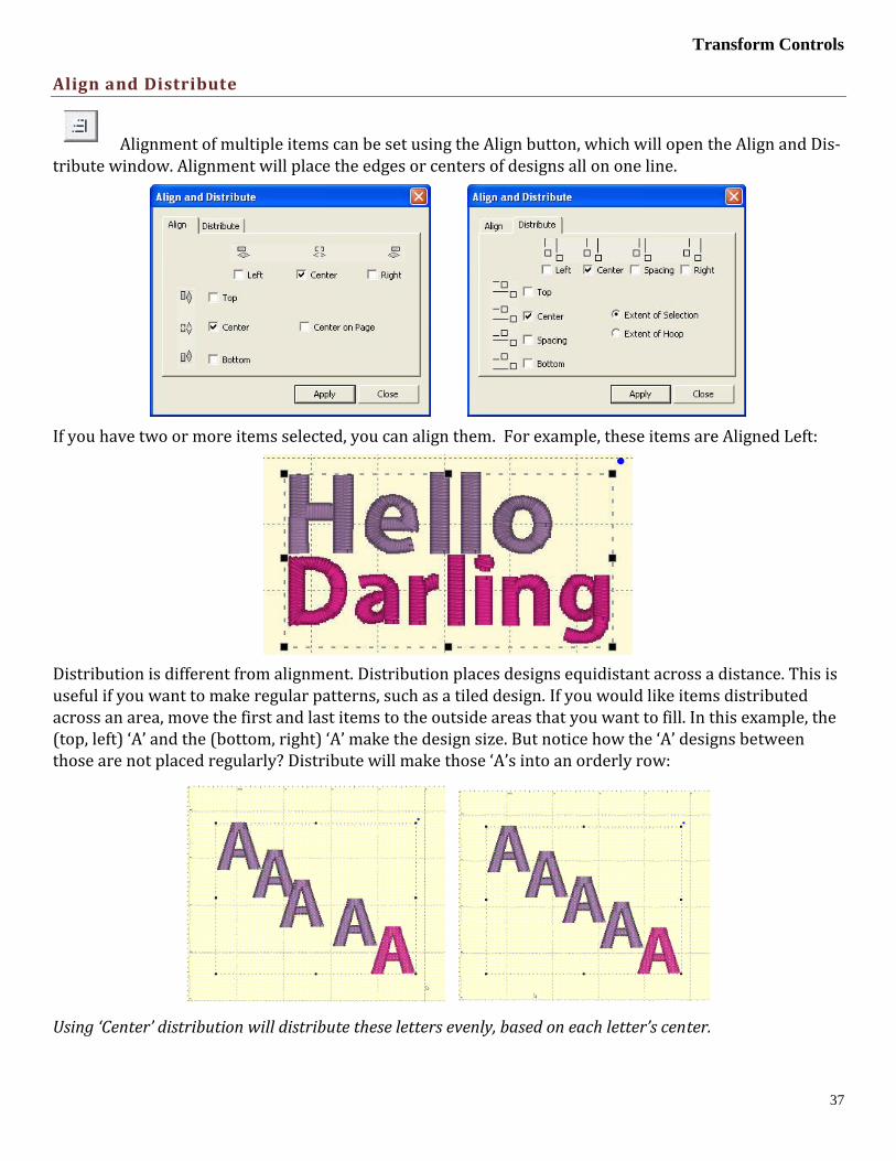
Transform Controls
37
Align and Distribute
Alignment of multiple items can be set using the Align button, which will open the Align and Dis-tribute window. Alignment will place the edges or centers of designs all on one line.
If you have two or more items selected, you can align them. For example, these items are Aligned Left:
Distribution is different from alignment. Distribution places designs equidistant across a distance. This is useful if you want to make regular patterns, such as a tiled design. If you would like items distributed across an area, move the first and last items to the outside areas that you want to fill. In this example, the (top, left) ‘A’ and the (bottom, right) ‘A’ make the design size. But notice how the ‘A’ designs between those are not placed regularly? Distribute will make those ‘A’s into an orderly row:
Using ‘Center’ distribution will distribute these letters evenly, based on each letter’s center.

Designer’s Gallery Platform
38
If you choose a different edge to distribute with, for instance, Left, then the distribution will be made us-ing the left edges of all the designs. This can be useful to create a geometric composition with different sized designs.
Mirror X4
From the Utility menu, select “Mirror X4.” This will call up a window that lets you create a pattern of designs, copied from the current selection, and pasted into mirrored corners.
To change the values, you can click the arrows next to each value, or type in a value and then click on an-other one to set it. As you change the values, you will see your result on the main view. Click OK to accept your new designs.
Above: An example of a Mirror X4 design.
Notice how the preview enables you to see the pattern as you adjust it. This preview is quite helpful if you are trying to fit a specific area, for example the hoop.
Note: The initial design will be the (top, left) design, and the copies will go to the right and down.

Transform Controls
39
Scatter
From the Utility menu, select “Scatter.” This will call up a window that lets you create a pattern of designs, copied from the current selection, and pasted in random locations based on your dialog box selections.
To change the values, you can click the arrows next to each value, or type in a value and then click on an-other one to set it. As you change the values, you will see your result on the main view. Click on New Pat-tern to generate a new random pattern based on the selected values. Click OK to accept your new designs.
Above: An example of a Scatter design.
Notice how the preview enables you to see the pattern as you adjust it, which helps if you’re trying to fit an area, for example the hoop.
Note: This is a way to get a random repeat of similar designs.
Instant Repeat (Advanced)
From the Utility menu, select “Instant Repeat.” This will call up a window that lets you create a pattern of designs, copied from the current selection, and pasted in rows and columns.
To change the values, you can click the arrows next to each value, or type in a value and then click on an-other one to set it. As you change the values, you will see your result on the main view. Click OK to accept your new designs.
Above: An example of a repeated design and the Instant Repeat controls.

Designer’s Gallery Platform
40
Notice how the preview enables you to see the pattern as you adjust it, which helps if you’re trying to fit an area, for example the hoop.
Note: The initial design will be the (top, left) design, and the copies will go to the right and down.
Precise Position (Advanced)
You can precisely position designs using these controls in the Advanced version of the program. The three buttons on the (top, left) control the display of the x-axis position. There are Left, Center and Right, which means that when you have the Left button set, the display will be of the left edge of the design.
Similarly, the bottom three buttons control the vertical axis, top, center and bottom respectively. The po-sition controls are very useful for creating tiled patterns.
Your best friends will be the top ruler and left ruler along the edge of the Design Page. You will notice that center of the ruler is “0”. To the left of “0” is -. To the right of “0” is plus. Let’s place a design on the design page and get started with Precise Position!
1. Decide what size embroidery hoop you are going to use and open it onto the Design Page. You will
notice that there are four quadrants inside the hoop.
2. Open a design onto the design page.
3. Place the design in the top left quadrant. Note the numbers in the x and y location boxes. (-47.17
and 50.25)
4. Select the design and right click to copy and then right click to Paste the design.
5. Click on Flip Horizontally .
6. Delete the “-“ from 47.53 and hit enter. This will move the copied design to the right top corner.

Transform Controls
41
7. Select the design and right click to copy and then right click to Paste the design.
8. Click on Flip Vertically.
9. Place a “-“ next to 50.14 in the y location box. (-50.14)
10. Hit enter. The design moves to the bottom right corner.
11. Copy and paste the design in bottom right corner.
12. Click on Flip Horizontally.
13. Place a “-“ next to 47.53 (-47. 53) in the x location box. Hit Enter.
14. Your frame is now complete!
This is a great way to align your designs without the frustration of where you placed the first design and how to get the others to follow suit.

Designer’s Gallery Platform
42
Carousel (Advanced)
From the Utility menu, select “Carousel.” This will call up a window that lets you create a pattern of de-signs, copied from the current selection, and pasted in an elliptical fashion
To change the values, you can click the arrows next to each value, or type in a value and then click on an-other one to set it. As you change the values, you will see your result on the main view. Click OK to accept your new designs.
Above: An example of a Carousel design.
Notice how the preview enables you to see the pattern as you adjust it, which helps if you’re trying to fit an area, for example the hoop.
Note: The initial design will be the (top, left) design, and the copies will go to the right and around.

Stitch Files
43
STITCH FILES
Clicking the Merge Stitch File tool found on the Design Toolbar or selecting Merge from the File menu will display the Open Design Files dialog. Here you browse for embroidery designs to add to the Design Page.
Left: Merge Stitch tool icon. Right: Menu option.
The Merge Design view allows you to browse thumbnails of your files and select one or more files in import.
• The Size control of this dialog determines the preview size of the design thumbnails (the design does not
have to be selected for the determined size). The 3D control shows the preview in 3D, i.e. it shows simu-
lated stitches.
• Click the Import control to bring the selected design(s) into the Design Page. The imported design will be
centered on the Design Page.
Merged Stitch File behind Monogram

Designer’s Gallery Platform
44
The Sweep
The Sweep function, which is run from the button with the broom on it, will remove hidden and nested stitches within designs, as well as removing hidden stitches where designs are overlapped.
These patented filters operate on the colors of a design to help reduce the stitch count, removing excessive overlays and stitches that tend to ‘ball up’ on the underside of the fabric.
Removing hidden stitches occurs as the program examines the design, looking for color layers that over-lap more than is necessary for compensation. If stitches of one color layer are on top of the stitches for another color, and those stitches are not visible, they can usually be removed. Stitches that would be overlapped at the edges of the colors are important for the design so as not to have gaps, thus they are not removed. What you get is a reduction is stitch counts, a reduction in sewing time and a reduction in puckering.
Note that the Sweep is different from the process that removes stitches from overlapping designs. The Sweep operates within a single design, whereas overlapped designs are ones that are merged in separate-ly and then laid on top of each other. The processes are similar, but different in that way. Another differ-ence is that the Sweep filters are not temporary; they are re-run on the designs as they are adjusted (for instance by sizing.)
De-Clumping is a process where stitches within a single color are eliminated if they will gather up in small areas. These clumps of stitches can often prevent the hoop from moving freely by forming a ball under the fabric which can anchor the needle in one area. When and if the hoop finally pulls away, the us-er often hears a ‘clunk’ sound and their project will probably have a gap, as registration may have been lost.
Occasionally one of the sweep filters will leave an undesirable result, which is visually evident. As a rule, these filters do a great job, and if the design looks good on the screen, it will sew nicely. However, if you see something onscreen that you don’t like, you can prevent the Sweep from running on individual colors using the Stitch Properties tab.

Stitch Files
45
Stitch Properties
The stitch properties tab appears when a stitch design is selected. There are controls where you can add or remove up to 25% of the stitches by increasing or decreasing the density of the selected items. The slider controls will separately allow the adjustment of satin stitching and fill stitching, which allows very specific control.
Note: You can also prevent Sweep operations for occurring on certain objects or designs when you want to.
If you are an EmbroideryWorks Advanced user, there are additional controls which also tie in to the Pro-ject Advisor and the StitchPerfect system.

Designer’s Gallery Platform
46
Stitch Properties (Advanced)
The Advanced version of EmbroideryWorks allows for more control of the stitches using our StitchPer-fect system. The Stitches property tab adds controls to use the project settings from the Project Advisor to remove stitching, De-Clump, and limit the density.
Use Automatic Settings: makes use of the Project Advisor project to identify the fabric density, thickness, stretch and material being used. The needle penetrations are then adjusted accordingly.
Limit Density: Certain combinations of fabric and stabilizer have limits on the number of stitches per square millimeter. More than that causes poor stitching or puckered fabric. Using the Project Advisor, the limiter will reduce the stitch counts in the affected regions.
De-Clump: Within sewing a single color, areas sometimes get too many stitches overlapping in small groups. These areas form clumps of thread on the back of the fabric which can become entrapped in the needle plate. Sometimes this traps the embroidery in one place and cause loss of registration. De-Clump reduces these stitches.
Remove Underlap (intra-design): Often a design has color layers that have some overlap for the purposes of registration. However, many times these regions are a result of auto-digitizing and poor results follow. The so-called, “Bulletproof Embroidery,” is an example. When stitching enters an area within a design that will be covered by a later color, those stitches can often be removed, and that is what this does.
Note: This is different from removing hidden stitches created by overlapping separate designs, such as in a composition. This filter works within a single design.

Project Advisor
47
PROJECT ADVISOR
The Project Advisor is a patented expert system, a form of artificial intelligence, which helps you select stabilizer, needles and hooping techniques for many common projects.
The system also provides instructions, helpful how-to advice and some words of caution when necessary. First, you select a project from the list. If your exact project or fabric is not listed, there are enough choices available where you can choose something very similar. Next, you can tell the Advisor if your fabric has more or less stretch, and you can adjust thickness. The Advisor takes your input in ac-count as it makes its recommendations, which are displayed as text in the window.
Both the backing (under the fabric) and topping (on top of the fabric) stabilizers are recommended.
EmbroideryWorks Advanced users will also have the StitchPerfect system, which extends the Project Ad-visor settings to actually adjust your designs’ stitches for the chosen project.
StitchPerfect (Advanced)
When you have chosen a project, the Advanced version of the program lets you set that project on the de-sign page so that the Stitch Perfect filters can use it.
If you would like to clear your project, you can click on ‘No Project.’
The StitchPerfect system stores information such as Fabric, density, stretch and stabilizer to help the fil-ters for stitch files minimize the pucker and gather that occurs when designs are used on lighter fabrics than for which they were digitized.

Designer’s Gallery Platform
48
OTHER UTILITIES
Add Knockdown Stitching Utility
When sewing on terry or any fabric with loops and nap, generally a topping stabilizer is used. These can be helpful, but have a limitation: They do not hold down the nap past the actual stitch, which means outlines can be lost in the surrounding fabric. Using the menu Utility->Add Knockdown Stitches you can create a gloabal underlay for the entire design. The underlay extends a few millimeters past the edge of the design, which helps the overall effect.
Save Image
You can quickly save a transparent .PNG file of your design page with this item, found on the Utility menu.
This is useful for putting designs on the web, in print, etc. The images above were created with this utility.

Other Preferences
49
OTHER PREFERENCES
There are a number of preferences for the program and design page that can be adjusted. Click on the Preferences button to reveal these controls.
Embroidery Hoops
In the Preference window, under Environment, you can choose a hoop. Hoops are displayed in a sorted list, organized by embroidery file format. Most embroidery hoops are made using the metric system, so the sizes for the hoops are displayed according to the way the manufacturer sells the hoop.
There are two types of hoops offered by the platform. Those are Normal hoops and Multi-Position hoops. Multi-Position hoops are those which offer more sewing area than the machine can sew at one time. So the hoop (or fabric) gets repositioned to allow a larger design to be sewn.
There are many hoops that are built into the program, and you can add your own. As the program up-dates over time, or if you have edited a hoop, you can use the “Defaults” button to restore the program to the hoops provided. The “Default” button will not, however, remove any hoops you’ve added yourself.
Many times you will want to sew a design sideways in the hoop. But rather than laying out your design sideways, it might be convenient to have the hoop displayed as rotated. Checking the “Rotate 90” button accomplishes this.
If you have added a hoop, or if you decide to have the program display only the hoops which you own, you can delete hoops from the list, using the “Delete” button.
You can create hoops and edit hoops too.

Designer’s Gallery Platform
50
The width and height fields are self-explanatory, and you can name your hoop as desired. Hoop names should be unique. Note that in EmbroideryWorks Everyday version of the platform you cannot create or edit Multi-Position hoops, but you can do this in EmbroideryWorks Advanced.
Note: Do not create a hoop that is bigger than the sewing field of your embroidery machine.

Other Preferences
51
File Conversion
Designs can be saved into many different formats. The Conversion Preference allows you to adjust some parameters when you save in those different formats.
The file format itself may have inherent limitations on the number of colors or stitches, such as the 16 color limit in .PCS. But there are also machine limitations too. Older machines which use the .PES format had limits of 100 colors, whereas the newer ones can go to 127. To help you save files correctly for your machine, there are options for some formats, such as .PES.
PES Files have to support two distinct machine types, and also have different data for the support of card reader/writers which many .PES machines required. Let’s look at the .PES options more closely.
“Use version 5 and later for real threads.” This setting exists because the version 5 of the Palette/PE-Design software, which invented the .PES file, added support for real thread colors. This was a wonderful addition for this format. However, if you own an earlier version of the software, and you want to use files created in the platform, then you need to leave this set to “Force version 1.” The reason is simple: The old software simply cannot open those version 5 files.
The Machine specific settings are for machines like the Ellegante which takes the 180 x 300 hoop (while other machines may not be able to accept this hoop, so why write a file for it.) Or the multi-needle ma-chines, which have their embroidery field rotated to a landscape position. So a 200x300 or a 300x200 field, while technically the same size, have different rotational parameters.
Certainly you know if you have a multi-position machine, or require the use of older software to write your card. If not, or if you are distributing these designs, please just leave the settings as-is. The program actually finds a Lowest Common Denominator in the format that it will output, making the file available to the widest range of users.
DST and EXP Files have a different type of information contained in them where it pertains to jump stitches. Rather, those formats have to have some number of “Jump” commands in a row before they will cycle their thread trimmer. When making a DST file, and converting from something else, these jump commands need to be translated. As machines differ in setup for the number of commands needed to cy-cle the trimmers, we offer this setting in the conversion preferences.

Designer’s Gallery Platform
52
Preferred Stitch Format
Most embroiderers have one machine or other that they use most for embroidery and that machine has a format that it uses. To save time, the format that you choose here will automatically be selected during the save.
Removing Overlaps Preference
When creating a composition, you can arrange designs so that they overlap. The platform automatically removes the overlapped stitches using our patented system. When you save your design, the stitches will be automatically removed. If you prefer this not to happen, uncheck the box and click Apply.
Auto Recover
Auto recover will save your file in a separate space every so often. This is adjusted using the slider. This feature is useful when working on a complex arrangement where a power outage or program crash (un-likely) or freeze by the operating system (it happens) could force the program to quit and you might lose your work. If you are working while power-outs are happening, well, turn this on. And don’t run your embroidery machine; brown outs are not good for them.
Checking For Updates
The program can check for updates if it is running on a system connected to the internet. This will occur once each day, the first time that you run the program. The program does not send your information or anything about you or your computer to us. It merely checks the current version available online for your program and if there’s an update, it lets you know. If you don’t want this, you can turn this off.
You can also check for updates at any time from the option in the Help menu.

Sizing of Design Files (Advanced)
53
SIZING OF DESIGN FILES (ADVANCED)
When you resize a regular stitch file, the density would normally get more or less dense, but The platform will recalculate the stitches for you automatically.
That recalculation process is complex and difficult, so there are some settings you can adjust to achieve optimal results. The sensitivity control is used to control how well the program discovers fills and satin stitches. If you have a design which has a lot of manually created stitch effects, then you may want the sensitivity higher, whereas normal designs that are digitized with objects like fills probably don’t need so much sensitivity, especially if there is blending going on.
• Gap Reduction is a function within the software that helps adjacent areas lessen gaps that might be ex-
posed or widen during increases in size.
• The stitch length filters are used to prevent loopy stitches on the fabric from stitch elongation, and in the
other direction, small stitches from gathering on the fabric making too many perforations or simply
bunching up the fabric.
The settings are broken out by stitch type because the handling of satin stitches is special and you may want to achieve a split-satin look at a certain size.

Designer’s Gallery Platform
54
LETTERING
Creating a simple letter design or monogram is, well, simple! Just click the Create Letters tool found on the Design Toolbar. This action will place the new lettering in the center of the design page and display the Letters Property tab.
Lettering Button Design Toolbar
Monograms vs. Letters
Traditionally, monograms were a single letter—“mono” meaning one and “gram” referring to the letter. Today most monograms are 3-letter combinations with the center letter larger than the outer two.
Fonts or letters styled specifically for such monograms are prefixed with “MGM” to easily distinguish them from more standard fonts. Of course, you can make a monogram with any font style and use the en-veloping features to shape the design.
Left: Monogram using MGM Diamond Right: Monogram Properties on the Single Line Page
Now, set the monogram to your desired value by typing into the Text box and pressing the ‘Enter’ key.
Selecting Letter Type
Although the fonts prefixed with “MGM” are designed for traditional three-letter monograms, you are by no means restricted to three letters. For example, if you just want the large center letter, enter a space and the character you want.

Lettering
55
Type a space before a letter for a large single letter
For fun, you can use a monogram font with entire words. This method works best with all capital letters and shorter words.
Sample above uses MGM Rounded applied to a word.
Overlapping letters is sometimes needed for your design, and when you do that within a lettering object, the stitches that are hidden will be removed automatically:

Designer’s Gallery Platform
56
Customize the Design
The Letters Property tab provides a number of tools that allow the design to be customized.
There are three basic styles for lettering:
• Multi-Line Text
• Single line of text or Monograms
• Text on a Circle
The lettering design can switch between these styles using the three buttons at the top of the property tab as shown above.
Multi-Line Text is useful when you want to enter an entire saying, poem, etc.
Single line of text or Monograms is useful for entering a single line of text or a Monogram. With a single line of text there is more flexibility in the shape such as the enveloping feature. With Monograms there are some fun Quick Styles that re-shape the 3-letter monogram and when overlapping the mono-gram letters the Sewing Order finishes the look.
Circle Text wraps around a circle. If you overflow the amount of letters that can fit on the circle, you will see your text spiral outwards. To see the text on a circle, you will have to adjust the ‘Radius’ of the circle using the slider.
Spiral text starts in the center.
When writing on a circle, you have the option to put text either on the inside or outside; when embroider-ing, we usually think of this as text at the bottom or top of a circular patch or badge. To switch this, use the checkbox labeled “Place on bottom.”

Lettering
57
Monogram Font and Quick Style
The font and style are changed using the selections in the Font and Quick Style boxes.
When the lettering is initially placed on the page, the letters are auto-matically kerned (letter spacing) for a good visual effect. Note that these styles are designed to accomplish traditional monograms, and therefore some only work properly with two or three letters.
Quick Style menu
Font Selection
Some fonts may only have uppercase letters. If you’re using a font and not seeing the desired characters, clicking the ‘?’ button to the right of the Font box; it will display all characters available in the selected font along with size recommendations.
Characters available shown with recommended size ranges.
Slant and Space
The slant of the monogram and the spacing of the monogram letters are controlled with the Slant and Space slider controls. If you use these controls and want to return the monogram to its default settings, simply click the zero control. This will restore the default setting. The Slant gives an italic effect to the monogram.
.
Enveloping
The envelope (containing top and bottom outlines) of the lettering (single or multi-line) can be individu-ally customized. The Envelope Type box and Envelope Slider control the envelope. There is an Envelope

Designer’s Gallery Platform
58
Slider control for the envelope top and there is an envelope slider control for the envelope bottom. There are four styles of envelope: Curve, Grow, Peak and Shrink.
If you use these controls and want to return the lettering to its default settings simply click the zero con-trol.
Enveloping
Curved Top and Bottom Envelope
Enveloping can produce a variety of creative designs, especially when you begin breaking up the words into segments and enveloping each one separately.
Sample above uses two envelopes and a lower case “o” resized for bubbles.
Changing the Color of one Letter
You can change the color of one letter by selecting that one letter. To select it, first make sure the lettering object or monogram is selected, then click on the green handle that appears centered over the letter you want to change. Once a single letter is selected, you can change the color(s) of just that one letter using the color property page as described previously.
For more information on threads and colors, see the section on Color.

Lettering
59
Monogram Sewing Order
On the Letters tab there is a Sewing Order box. Choose the order in which the letters are sewn from this control. For a simple monogram you probably do not want to change the default order. However, if you want to overlap the center letter on the others, you could choose the ‘ACB’ order (second choice).
Stitch Properties
The Stitch tab contains controls for the actual stitch generation of the Lettering.
Note: This tab will not be displayed for imported fonts, as those designs are different in nature.
Auto Fill: If you want the lettering design to be a satin stitch at any size, uncheck this box. This prevents the program from switching this design to a fill as it gets larger.
Fill control: When switching to a fill, there are options for the pattern to be used. Click the arrow on the right to open the list.
Satin Density Control: This control ranges from 3 to 20 with each tick being one tenth of a millimeter. So the range in millimeters is .3 to 2.0 mm. The smaller the density number the closer together the satin stitches will be. 0.4mm is normal.
Compensation: This control ranges from 0 to 10 with each tick being .1 millimeter. As the value increases the stitch length increases, in effect ‘fattening’ the stitching. This is useful on fabrics that have a loft or nap, and can also be used to make a font appear bolder.
Remove Hidden Stitches: When selected, stitches that are completely hidden by top stitches will be re-moved. This process allows the design to sew out in a flatter manner. Note that this only affects stitching within the monogram itself.
Edge Run: When checked, this adds a running stitch underlay. This setting is the amount of inset for the edge run and ranges from .1 to 1.2 mm.
Satin: When checked, this adds a satin underlay. When checked, it applies the density value, which ranges from .3 to 2.0 mm just like the satin stitch.
The ‘Set Defaults’ button restores each of these controls to their default values.

Designer’s Gallery Platform
60
Monogram Placement
Towels
General Instructions: The placement goes on the opposite side of the fabric and at the opposite end from the la-bel. This allows a traditional triple fold to display the monogram. Folding the towel as you would display it helps visualizing and marking the correct placement.
Bath Towel: The bottom of the monogram should be 4” above the hem or 1”to 2” above the dobby border, if pre-sent. The monogram should be 4” tall.
Beach Towel: The bottom of the monogram should be 5” above the hem or 2”to 3” above the dobby border, if pre-sent. The monogram should be 5” tall.
Golf Towel: The monogram should be centered horizontally with the top of the monogram .5” below the grommet. The monogram should be 1”to 2” tall.
Hand Towel: The bottom of the monogram should be 2” above the hem or 1” to 1.5” above the dobby border, if present. The monogram should be 3” tall.
Sports Towel: The bottom of the monogram should be 1.5” above the hem. The monogram should be 1.5” tall, and may be placed on a 45 degree angle.
Wash Cloth: The bottom of the monogram should be 1.5” above the hem or 1” above the dobby border, if present. The monogram should be 1.5” tall and may be placed on a 45 degree angle.
Bedding
General Instructions: Don’t annoy your sleeper. Placement and thread can affect the comfort of the item. Spread out the item as you would see it on a well-made bed to help with visualizing and marking the correct placement.
Top Sheet: Top Sheets are placed on a bed upside-down and the top (wide hem) is then folded back to right-side-up. This means that the monogram is apparently embroidered upside down. Looking at a made-up bed will help you visualize this. Place the bottom of the monogram 2” from the wide hem, centered. The monogram should be 3”to 4” tall. Embroidering inside the wide hem is sometimes preferred, and when doing so the design is sized to fit.
Pillowcase: Embroidering inside the wide hem is generally preferred, and when doing so the design is sized to fit. If the font allows it, the monogram should be 2.5”to 3” tall. Placement is centered, monogram facing toward the opening.
Pillow Sham: Center the design on the sham, facing the long edge as if it were a pillowcase with an opening. The monogram should be 2.5”to 4” tall.
Blanket: Centered on the top like a sheet or facing into the bottom, right corner at a 45 degree angle. The mono-gram should be 4” tall.
Duvet Cover: Centered on the top. The monogram should be large, up to 12” tall.
Home Decor
General Instructions: None. This is all according to taste, fashion and style.
Napkin: Embroider 2” in from point of corner. Distance may need to be increased if there’s a border or hem. Place opposite of label or tag. The monogram should be 1”to 2” tall.
Placemat: Top-right corner, 3” diagonally from point of corner. The monogram should be 1”to 2” tall.
Table Runner: Embroider matching designs 4” from end. The monogram should be 4”to 5” tall.
Table Cloth: Embroider 4” from corner, with design facing into corner at a 45 degree angle. The monogram should be 4”to 6” tall.

Lettering
61
Garments
Coat Lining: Embroider on the right side at the waist level, 3” from the seam. Monograms should be 1” to 1.25” tall.
Collar: Embroider on the left side, above buttonhole if present. Monograms should be 3/8” tall.
Golf/Polo Shirt: 7.5” to 9” below the shoulders left seam and 4” to 6” from center. Depending on the de-sign, you can also look for a line down from where the collar meets the shoulder seam, and look over from the 2nd buttonhole.
Long Sleeve Shirt: Top and center of wrist, which is about 1” to 1.25” from the center toward the but-tonhole. The bottom of the monogram should sit very near the top stitching of the cuff. Monograms should be 3/8” tall.
Robe: Draw a line straight down from the shoulder seam 4” to 6” for women and 7” to 10” for men. Find the center of the armholes from the armpit to the shoulder, and draw line straight across toward the cen-ter of the robe or go across 3” to 5” from the center.
Shirt Placket: Center the design between 2nd and 3rd buttonholes. The design should be 1/4” to 3/8” inch tall.
Shirt with no pocket: Draw a line straight down from where the shoulder seam meets the collar seam. Find the center of the armholes from the armpit to the shoulder, and draw line straight across toward the center of the shirt. The center of the design is marked where the lines intersect. If the arm holes are deep, the line can be made too low on a woman’s shirt, so keep that in mind.
Shirt with pocket: Center the design on the pocket hem, with the top of the design 1/4” below the top of the pocket. Monograms should be 1/4 to 3/8” tall. If pocket has button in center, shift design to the right.
Shorts Leg: Halfway between center-front and side seam. The bottom of the design should be 1/4”to 1/2” above the hem stitching at the leg hole.
Short Sleeve Shirt: Center design 1/4”to 1/2” above the hem on the sleeve. Monograms should be 1/4”to 3/8” tall.

Designer’s Gallery Platform
62
THE LIBRARY
Clicking the Library tool found on the Design Toolbar will display the selection dialog.
The dialog has a pulldown list at the top that allows you to select from different library collections that may be available to you depending on the version of the software that you have. Next to this pulldown menu is the Import Catalog (.bx) button that allows you to install new library collections.
The dialog has a scrolling list on the left that shows the collections. Select a collection from the list on the left and designs in that category display in the selection area on the right. Select a design and click OK. The design will be placed in the center of the Design Page.

The AccuQuilt Libraries
63
THE ACCUQUILT LIBRARIES
Various families of the AccuQuilt dies have been made available as embroidery applique files in the li-brary function. They are first downloaded from the Designer’s Gallery website, then use the button “Im-port catalog (.bx)” to load the individual catalogs. These catalogs will grow and change over time as Ac-cuQuilt releases new dies.
Select the family from the catalog pulldown menu and choose the die you wish to use from the list on the left. The individual pieces may be selected one at a time, All at once (using either CTRL+A or the “Se-lect All” button) or multiple selections using the CTRL or Shift keys.
Click OK to insert the current selection into the center of the design page.
Each die-cut design that is inserted has its own properties that can be modified.
Thread Brand and Color:
The thread brand and color are changed just as described in Color section. The color of the Fabric pre-view is calculated from the color of the finishing stitch.

Designer’s Gallery Platform
64
Applique Properties Tab
This tab becomes active when you have an applique shape from the Library selected. The default is to not show the fabric of the applique shapes. This feature will give you a realistic view of the finished design, and can be turned on by selecting the Fabric Preview option.
The border style pulldown menu allows you to change the finishing stitch type. In this example you can see the E-Stitch is selected and will hug the edge of the precut AccuQuilt die for professional and clean results. With pre-cut appliqués a heavy satin-stitched border is no longer necessary, saving time and thread while improving the finished look.
The Topstitch (finishing stitch) properties can be adjusted in this section. You may type in values for the Stitch Length and Stitch Width or you may use the slider control for each value on the right.
The Color style allows users to adjust how they work with color during appliqué steps. There are two styles: Keep Color and PES Card (Traditional).

Multi-Position Hooping
65
Use Keep Color to conserve thread changes by combining like colored Top Stitch and next position placement stitches. This will allow the machine to stitch the finishing stitch of the piece and the place-ment stitch of the next piece (if the same color) without having to start the machine again.
For traditional stops after each section, you may select the PES Card option from the Color type pulldown. This selection may be necessary depending on your machine, particularly if you use Palette Basic or simi-lar to write a PES card for your machine.
Once you have selected a color style, the program will remember it as your choice for next time.
MULTI-POSITION HOOPING
So, you saw it on the Internet and had to have it.
But it’s too big for your machine…
The platform has our patented design splitting technology built into it. This system automatically splits designs into multiple positions for sewing as separate designs which tile together to make a larger design. In the past, splitting a design took hours of editing by a person schooled in the process.
Our splitting drastically reduces the visible ‘seams’ that occur from manually splitting files using an edi-tor. In most cases, the final product is indistinguishable from one created on a larger-field machine.
Some hoops have multiple positions. This means that you only hoop the fabric once and generate the de-sign by sewing it in those multiple sections. However, you can achieve the same result by re-hooping the fabric multiple times to create the design. We call this a “Virtual Hoop.” The Everyday version of the pro-gram comes with many hoops and virtual hoops pre-defined. The Advanced version has creation and ed-iting of these hoops as well.
When sewing designs in multiple sections, often the question of alignment comes up. This is accom-plished automatically with multi-position hoops, but to make it easier for regular hoops, the program will add basting stitches which will align the designs. To choose a hoop, click the preferences button on the toolbar, and the Hoops window will appear:
The Multi-Position hoops are separated from the Normal hoops, and you click on the Hoop Style to select which list you want to see. Here is the Jumbo Frame:

Designer’s Gallery Platform
66
Sewing
You’ll notice that this hoop has two rectangles, which overlap in the middle. Each of these represents a sewing field. To make it more obvious which lines represent which field, the inside of each rectangle has a dotted line indicating the inside of the field.
If you are combining designs to make a composition, it is always going to give the best result if you keep whole designs into one region. This produces a split which will have the least effect on the actual stitches on the design. Of course, this is not necessary, however, as the design may be split even if it lies in the middle of the hoop, but some splitting would have to occur.
The ‘+’ marks shown indicate the centers of the sewing fields.
Note: If you look at the Hoop in the selection window you will see a note that the design centers are offset from each other. This means that when you sew the two sections, the centers of each design will be sepa-rated by that amount. This is your initial placement method for each design.
In order to position your design, it is always advisable to print an actual template of the design. This helps you visualize what it will look like once embroidered, and it will help define the center position of the de-sign on the fabric. Once you have the center of the overall design, then you will want to mark the centers for the individual fields. In the example above, this would mean that you mark the fabric 5 cm. from the center on both the left and right of the design center. This places the two designs 10 cm. apart. This basic positioning will help you get the result onto the fabric where you want it to go.
Multiple Hooping
Multiple Hooping is the process of creating a large embroidery design by re-hooping the fabric as you embroider each section. Multiple Hooping is an art that requires a complete understanding of what you are doing, as well as an excellent ability for placing your fabric in the hoop. It is not a method that should be practiced by the timid. You can split designs for Multiple Hooping by creating your own hoop:
Suppose you have a design that is 9 inches high and 8 inches wide. Also, suppose that your machine will embroider a region 9 inches high and 6 inches wide. (These are typical values for today’s machines.) What you want to do is to create a two-position hoop to accomplish the split.
Therefore, create a hoop that is 9 inches high, with two positions. The separation should be set to allow the greatest possible overlap between the two regions: 8 inches (desired) - 6 inches (a single hoop width) = 2 inches.

Multi-Position Hooping
67
A separation of 2” would be the smallest possible for the desired 8-inch width, and would provide the greatest overlap of the regions.
Note: The use of columns allows side-by-side multiple-position hoops. It’s a lot of embroidering, but it looks good and can easily fill a jacket back.
It is very important to mark your fabric before embroidering. When the fabric is re-hooped it must be parallel and centered to the first hooping. Also, the distance between the centers needs to be precise. (This is 2 inches in this example.)
If it is possible, we encourage the use of ‘Floating’ techniques for hooping: not actually hooping the mate-rial itself, but rather hooping a stabilizer and attaching the fabric to it with adhesive and/or a basting stitch. This will provide the least distortion in the fabric while the overlapped regions of the design are being embroidered. One easy method, if your material can handle it, is to use carpet tape (double-sided and very sticky) on the bottom of your tightened hoop. This can then be perfectly aligned and pressed in-to place. (The adhesive comes off with a lot of water-soluble solvents and even soapy water will usually work.)
Remember:
It is a really good idea to take a class on this type of process to get the hang of it, and practice before mov-ing on to an actual project!
Output Files
When you save your files, the output files represent each region of your design.
The files are automatically given names indicating their stitching order as well as the position within the hoop. For instance, “Rose.Pes” may split into “Rose Top #1.Pes” and “Rose Bottom #2.Pes”.
Additionally, you may get a text file that explains the color sequence for your new files. In many designs, a color is only needed in one region. Where this is the case, that color will not exist in all the output files. To help reduce this “Color Confusion”, a text file is created with a table. The following is text from an exam-ple file:
“Roses.Pes
Your original file had 3 colors.
The program has split your file into 2 segments.
This cross-reference has been created for you because some thread colors in the original file were not needed in some of the split segments.
File: C:\Roses Top #1.PES
Color 1 = original color 1
Color 2 = original color 2
Color 3 = original color 3
Color 4 = original color 4
Color 5 = original color 5
File: C:\Roses Bottom #2.PES
Color 1 = original color 1
Color 2 = original color 2

Designer’s Gallery Platform
68
Color 3 = original color 3
Happy Embroidering!”
As you can see, the table is easy to follow. Since this is a text file, you can view it in Designer’s Gallery Stu-dio. You can also edit it (double-click to launch Notepad), print it, etc. It is a good idea to add any real thread numbers or names if you have them. Often, the digitizer of a design will supply a real-color thread list for this purpose.
We cannot stress enough the fact that the order of embroidering the files is important.
The files will overlap each other as they sew. If you embroider out-of-order you will get overlapping that is incorrect, and parts of your design will not be visible!
Region Naming:
On hoops that have three positions, the regions are named for you: Top, Center and Bottom. On hoops that have more positions, the other positions are given numbers, starting at the top. Hence, you might have a hoop with: Top, Pos. 2, Center, Pos. 4 and Bottom. Columns have names like “Left”, “Right” or “C2”.
Getting Results
To get the best results, there are some things you should know.
First is that you should trim your jump stitches as you go, if your machine does not do it automatically. This is true in the course of normal embroidery, but somewhat necessary when embroidering a split de-sign. When splitting a design, it is natural that the machine will have to go from place to place a little more frequently. This results in extra jump stitches. We have made every effort to minimize the amount of effort that it takes to split embroidery files, and apologize for any inconvenience this may cause, but please accept our assurance that your finished product will have a nicer appearance if you clean the jumps from the design.
If you are using an appliqué design, you will need to embroider each color in each region before moving on to the next color. This will ensure that the full appliqué can be applied without incorrect oversewing by the other colors.
There is a compensation control in the Hoop Properties window. This control is available on all hoops, even the factory-defined ones. Compensation is the amount that each region will overlap the neighboring regions. This is used to correct for the fact that fabric will shrink as it is embroidered. Additionally, an imperfectly hooped project will allow registration problems to occur. If you are not able to hoop your fabric, ‘Drum-tight’, then you may want to increase the compensation setting for your hoop.
Important: If you are increasing the size of a design in SizeWorks or some other sizing program, please don’t increase the size more than you will actually need for your hoop.
Note: There is a very important phrase in the computer industry: “Garbage in, garbage out.”

Stitch Simulator
69
STITCH SIMULATOR
The Stitch Simulator lets you see how the design will sew out by sewing on the screen. It is activated by clicking the Stitch Simulator tool in the View tool bar or selecting Stitch Simulator from the View menu.
Stitch Simulator controls
Stitch Simulator Controls
The controls are easy to use and give complete control of the simulated sewing process.
Player Control: This control lets you sew forward, backward and stop. The right arrow starts sewing forward. The double bars stop sewing. The left arrow starts sewing backward.
Step Stitch Control: This control lets you sew one stitch at a time forward or backward. Right arrow: forward. Left arrow: backward.
Speed Control: Use the slider to change the speed of sewing. Move to the left for slower to the right for faster.
Manual Control: Click and drag this slider forward or backward to quickly move a particular section of the design.
Stop Control: Click the Stop button to insert a color stop in the design. This allows you to change colors on the fly. Or creatively use this to isolate parts of the design that you want to remove or isolate.

Designer’s Gallery Platform
70
THE DENSITY MAP
The Density Map is a graphical display of the density, or stitches-per-inch in your designs. To see the Density Map, click the button on the main toolbar. This is useful to see if a design is not going to sew well. For instance, this is a design that has been overlapped, thus its density is very high.
Like weather radar, the density map shows areas where trouble is likely:
Where the design shows bright red in color, there are six layers or more of thread, which undoubtedly will produce poor embroidery results.
The Density Map can be used to illustrate when a design (probably from the internet) is dangerous to sew on a project without test sewing it first. And it also helps identify when you would want to you’re the Re-move Hidden Stitches function or even the Sweep. Those features will remove stitches that are likely to cause poor design production, while maintaining the same visual design. Here is the same design after a Sweep is performed:

Basting functions
71
BASTING FUNCTIONS
Individually selected designs can have a basting stitch added automatically. This is useful when you want to add a layer of stabilizer or some other material before the sewing of a design.
Also a basting stitch can be added to the hoop, which allows for a layer of topping stabilizer to be basted in place before any designs are sewn. A typical use of this is to add a layer of water-soluable topping to a towel, which will prevent the terry cloth loops from coming up through the embroidery. It can be hard to hoop a towel, and the topping stabilizer will want to slide around before the stitching happens, so basting it first can make the process easier.
The basting stitches are added to the start of the design or file, and are added as a separate color; natural-ly you can use any color you want to sew the baste.

Designer’s Gallery Platform
72
PRINTING
A design template showing the design at full size and with registration marks can be printed. Just choose print from the File menu.
On the left are common options for printing templates. This includes 3D and crosshairs which mark the center of the design for hoop placement. Also you can choose not to print design information (Design On-ly).
Several options have been included for use with Applique. See the Applique section for images and a de-scription of using the Applique.
‘Selected Colors only’, which can be used with machines that will scan and cut – by printing only an outline, you could make it easier for those machines to scan the shape you need.
When printing an applique for hand-cutting you probably want to turn the ‘Print Applique Outline’ mode on so that you have a clean, dark line to cut on.
The ‘Print Stitches’ option is used to only print a background image, for use with creating a photo-graph as an applique via printable fabric or transfer fabric. There, you want to print the image, not the stitches which will be applied over top.
‘Print Applique’ is a setting that turns on printing of a selected Simulated Fill or photograph (on the applique tab of the Color Window.
And ‘Mirror’ is useful for transfer paper as the image will be reversed.
‘Print Color Sequence’ adds a separate page with all the colors, see the following images:

Printing
73
The template can be previewed before sending the output to the printer. Below is a sample template with a monogram surrounded by a frame. Note the registration marks.
The second page of the worksheet displays size, stitch and color counts, and a list of the colors used in the design with approximate thread requirements.
Printing preferences, found in the Program Preferences window.

Designer’s Gallery Platform
74
EDITING THE HOOPS (ADVANCED)
When you click the “New” or “Edit” button in the Hoops Available window, you will see this screen:
EXPLANATION OF FIELDS:
• The first field in this window is the ‘Hoop Name’. This is just what it sounds like. Type in whatever
name you want.
• Next, choose the ‘File Type’ of the machine that this hoop works on. The list contains the file types that
can be saved.
• The ‘Individual Field Size’ is the size (in mm) that your embroidery machine can create with a single
hoop position. If you are unsure about this size, consult your dealer.
• The ‘Rows’ field specifies the number of vertical points at which the hoop can be attached to your ma-
chine. For most multi-position hoops, this number is three. For sliding hoops such as those made by
Hoop-It-All, you will have to determine how many sections you want to embroider in. In so doing, how-
ever, keep in mind that there should be a good overlap between adjoining sections. Use the hoops we’ve
provided as examples.
• The ‘Columns’ field specifies the number of points at which the hoop can be attached to your machine
sideways. For most hoops, this number is one, but there are exceptions on the market. These are usually
described as “Double-Wide”. You can also use the columns to indicate that you want to divide the design
into horizontally-tiled segments.
• The ‘Separation’ fields specify the distance between the hoop positions. (For example, the distance from
needle-center of the top position to the needle-center of the middle position.) This can be measured phys-
ically if you do not know: hoop a piece of paper and drop the needle through it, in all hoop positions,
measuring the distance between the holes. Alternately, most manufacturers’ software will show a grid
behind the hoop on the screen. You can count the grids (usually 1 grid = 10mm) between the region
marks to get the separation. It is very important that you correctly assign the separation; otherwise the de-
sign will not be split accurately.
• The ‘Right-to-Left’ field is used for multi-column hoops (‘Double-Wide’). It indicates that the initial di-
rection the program will split the design will be right-to-left, as opposed to the standard, left-to-right. The

Editing the Hoops (Advanced)
75
use of this depends on the machine and hoop. Some manufacturers have wide hoops that start by sewing
the left side of the design upside-down, then you turn the hoop halfway around and embroider the other
side (now the right side, and the design is right-side-up). Hence, the default, ‘Left-to-Right.
NOTE: You can tell if your separation figure is correct! The manufacturer of the hoop will definitely pro-vide you with the number of positions used as well as the full size of the embroidering region of the hoop. As you adjust the separation, the field, “Overall Size” is calculated. If this matches the figure given to you by the manufacturer, you have correctly set your separation.
• ‘Compensation’ allows the final regions to be slightly increased in size. This forces the regions to overlap
each other. This is useful because as the machine adds stitches, the fabric gathers slightly. It is entirely
possible to have a gap between regions if no compensation were to be used. The amount of compensation
required depends on several factors: The size of the hoop, the fabric being embroidered, the number of
stitches, the quality of the stabilization, etc. We have chosen some settings for our factory hoops that
have worked well in our design testing. Please embroider some test designs with the desired hoop before
tackling a project. This will ensure that you have a reasonable setting for your compensation.
• ‘Color-by-Color’ denotes a different type of file splitting. As of this writing, only the Viking Mega
Hoop™ allows for this type of design splitting, so as a general rule, never check this box. The Color-by-
Color method is for use in machines that can sew each color in all of the hoop regions before going on to
the next color. When the machine operates this way, it will stitch in its current region until it no longer
can. It will then stop and ask the user to reposition the hoop, whereupon it will continue stitching. In the
case of most designs, this will cause a lot of position switching as a color typically stitches objects out in
a random fashion all over the design. The program will ‘sort’ the stitch objects to reduce the number of
position-switches required.
• ‘Invert Alternate Column’ is used for ‘Double-Wide’ hoops that get turned upside-down for their second
row.
• ‘Add basting alignment lines’ will provide a basted line of stitching to each output file. These lines of
stitching will have their end and/or center points line up on the fabric when you go to stitch out the de-
signs. If the lines do not line up, then adjust your hoop/fabric position until they do.
• ‘Baste Length’ sets the size of the alignment line stitching, in mm.
Once you have finished creating or editing your hoop, simply click, ‘Save’ to save it.
If it is a new hoop, it will then appear in the Hoop Available window.

Designer’s Gallery Platform
76
Split Into Hoop (Advanced)
You can split the design using the “Split Into Hoop” from the Utility menu. This will open a new design page with the split files so that you can preview them or do other work before saving.
Left: A single design placed on a 100x172 hoop. Right: The design has been split.
In the example above, the 100 x 172 PES hoop was chosen, and the design was centered in it. Then the menu item, Utility->Split Into Hoop was chosen. This created a new design page, represented by a new tab. In that page there are two designs, one for the top hoop section, and one for the bottom. Using ghost mode, we show the designs separately:
Left: The top design is selected. Right: The bottom design is selected.
When you save this page, multiple stitch files will be created, as described in the next section, “Output Files.”

Importing Fonts (Advanced)
77
IMPORTING FONTS (ADVANCED)
There are many great fonts in the world, and lots of design companies are digitizing fonts as regular stitch files. The difficulty with these comes in using them: The letters have to be imported one at a time, there is no baseline, the sewing order can be messed up if you copy and paste; sizing and color sorting are issues to be managed too! Plus it would be nice to use the envelopes and text path tools that are used for the built-in keyboard lettering fonts.
For this reason, we have created the ability to import alphabet designs! This window is brought up from the Utility menu item, “Import Font…” and it lets you import fonts as well as manage ones you’ve already imported. Let’s take a look at the Import Font dialog box as it contains the mapping shortcuts as well as other useful information and tools. The following numbered picture shows you the tools and buttons in groups as they will be described below:
1. This shows you the name of the folder that you have selected. Below this is the name of the font as it will be shown in the font list of your program. You may change the font name and this information will be saved with it and displayed in your font list.
2. We have set the default spacing between letters and words which will be perfectly fine for most fonts that you map. If you find that these settings need adjusting, you may do so here and these values will be saved with your font. Included in the spacing section is a pulldown menu for the baseline. For most fonts that reside on a line, you would want the baseline to be at the bottom – a reference where the bottom most part of the design is. However, for some decorative or monogram alphabets, you may decide that the baseline should be at the Center or Top, so this maybe changed in the pulldown menu.
3. Here we have the buttons for adding a New font, Saving a mapped font, Deleting a font you have previously mapped and to Add Designs to an existing mapped font.
4. The trashcan button allows you to remove the current letter from the mapping process. The Letter: shows you the name of the current design – once it has been mapped, this field will show you the character on the keyboard that corresponds to the currently viewed let-ter.
5. The MGM pulldown is for mapping monogram alphabets – is the current letter a Left, Cen-ter, or Right monogram letter.
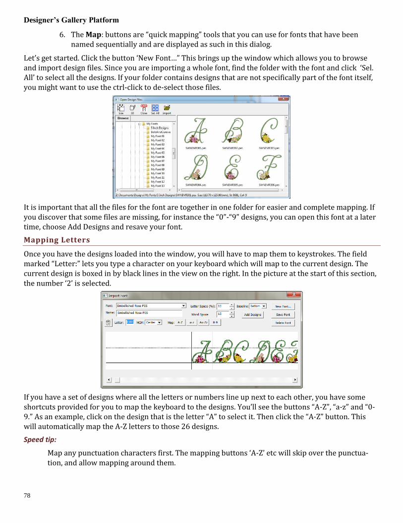
Designer’s Gallery Platform
78
6. The Map: buttons are “quick mapping” tools that you can use for fonts that have been named sequentially and are displayed as such in this dialog.
Let’s get started. Click the button ‘New Font…” This brings up the window which allows you to browse and import design files. Since you are importing a whole font, find the folder with the font and click ‘Sel. All’ to select all the designs. If your folder contains designs that are not specifically part of the font itself, you might want to use the ctrl-click to de-select those files.
It is important that all the files for the font are together in one folder for easier and complete mapping. If you discover that some files are missing, for instance the “0”-“9” designs, you can open this font at a later time, choose Add Designs and resave your font.
Mapping Letters
Once you have the designs loaded into the window, you will have to map them to keystrokes. The field marked “Letter:” lets you type a character on your keyboard which will map to the current design. The current design is boxed in by black lines in the view on the right. In the picture at the start of this section, the number ‘2’ is selected.
If you have a set of designs where all the letters or numbers line up next to each other, you have some shortcuts provided for you to map the keyboard to the designs. You’ll see the buttons “A-Z”, “a-z” and “0-9.” As an example, click on the design that is the letter “A” to select it. Then click the “A-Z” button. This will automatically map the A-Z letters to those 26 designs.
Speed tip:
Map any punctuation characters first. The mapping buttons ‘A-Z’ etc will skip over the punctua-tion, and allow mapping around them.

Importing Fonts (Advanced)
79
If your designs are organized in some other order then you will have to manually type those keys to map the font.
Adjusting Baseline
Sometimes individual letters require adjustments for their baseline. In the view, the pictures of each letter are shown, with a black line representing the baseline. You can click on a letter to select it, and once selected, drag the letter up or down as necessary to place it relative to the baseline as you like.
Some things like apostrophes always need adjustment, naturally, but letters with de-scenders like “g” or “y” will usually need adjustment also.
Spacing
The spacing of letters between each letter and each word can be set using these boxes. The spacing is al-ways a percentage of the font height.
Editing Fonts Already Imported
Use the Font box to select a font that you want to edit. Once the font loads, you can make adjustments to the font, such as remapping letters, adjusting sizes or positions on baseline, etc. When you have the font how you want it, click “Save Font.”
If your font is missing letters that you have now located, use the Add Designs button to open the Import dialog box to select and add the missing letters. You will need to map these new letters and save the font.
Note: Fonts must be named uniquely. If you accidentally name a font the same as an existing on, it will get a (2) added to the name.
Another Note: Long font names may run past the visible space on the font selection in the Letter proper-ties, so we recommend shortening the font names using initials or abbreviations. Do this in the Name line under the Font list box.

Designer’s Gallery Platform
80
Using Imported Fonts
When you create a lettering design, you can now use the font that you’ve imported. Imported fonts are indicated with a needle overlaid on their icon, as seen on the picture to the left. These fonts can do almost everything that the built in fonts can do, such as make monograms, circles and even be shaped. When these letters get sized, the built-in sizing technology will recalculate their stitches.
There are however, no stitch properties for these fonts, as they are stitch-files, not our digitized objects. So removing of hidden stitches, underlay and density cannot be changed, for example.
Note: If you see an imported font listed that has no characters displayed, it hasn’t yet been mapped. You can always import and save a font and then map the characters later.
Deleting A Font
At some point you may want to delete an imported font. From the Import Font window, select the font to remove from the Font list popdown and click the Delete Font button. Be sure this is what you really want to do because the program simply assumes you know what you’re doing and will instantly remove the selected font.

Stitch Editing (Advanced)
81
STITCH EDITING (ADVANCED)
The ability to edit individual stitches is a very useful tool. Sometimes there are parts of a design that you simply do not want. Other times, there are jams of stitches that simply cannot be re-moved any other way. In still other cases, you want to add a few stitches to get rid of gaps or in-
crease coverage in an area that’s not necessarily a fill. Maybe you just want to make a pocket topper?
To begin editing a design’s stitches, click the Stitch Edit button on the toolbar. This will cause the Tool pane to display the Stitch Edit controls, and the main view will show the stitch points:
Stitch points can be turned on or off from the View menu. They help identify the individual needle pene-trations in the design.
Selecting Stitches
The slider control at the top of the Tool pan scrolls through the stitches, highlighting the current one as you scroll. You can also move forward or back with the blue arrows. If you hold down the shift key as you scroll, you will be able to select a range of stitches.
Here you can see that we’ve selected a range of stitches inside the golf ball, but we’ve skipped the satin stitches that go around the edge. If we hit delete on the keyboard, we can remove them!
Another way to select stitches is graphically. You can drag a rectangle or a lasso around stitches to select them. You can also use the Brush selection, which selects anything the cursor touches, or with the Ctrl key, the brush can de-select points. Selected stitches can be deleted with the ‘delete’ key or split using the ‘Split’ button.

Designer’s Gallery Platform
82
You can also select stitches for an entire object or design using the Object View. While in Stitch Edit mode, simply select objects in the tree and the corresponding stitches will be selected.
Left: Lasso. Right: Selected
Splitting a design
Once stitches have been selected, you can delete them or split them, To split them, click the ‘Split’ button. This will create a separate design for the selected stitches. It will also remove the
stitches from the current design. If your design is lettering or a Library design, this process will convert that design to stitches so you will not be able to adjust that design the same as before.
Above, the design has been split, and the crown was copied and pasted.
Insert Stitches
If you have a stitch selected, you can right-click to get a pop-up menu which will let you insert stitches.
Notice that you can see the direction of the stitches when you are zoomed in. This helps determine ‘be-fore’ or ‘after’. The arrow on each stitch points toward the next stitch as the design would sew.
Left: Right-click to select the Insert mode. Middle: Inserting stitches. Right: Stitches have been inserted.

Stitch Editing (Advanced)
83
Converting Stitches
Using the ‘Satin’ Drop-down box, you can convert selected stitches to a satin stitch, a choice of split satin stitches, or even add a fill effect to an existing satin stitch.
Adding compensation
Once stitches have been selected, you can add compensation, which makes the outside stitches of fills or satins a bit longer or shorter. This is useful when you have gaps in a stitch-out and you would like to ‘stretch’ the stitches together, thus reducing or eliminating the gaps. You can also use compensation to adjust the width of lettering you may have imported.
Left: a typically gapped design. Middle: The stitches around the gap are selected. Right: Compensation has been added by moving the slider to the right.

Designer’s Gallery Platform
84
Stitch-Edit Keyboard Shortcuts
Left Arrow: Select Backwards
Right Arrow: Select Forward
Up Arrow: Select Forwards 10 stitches
Down Arrow: Select Backwards 10 stitches
Page Up: Select next command (jump or color)
Page Down: Select previous command
Home: Select First stitch
End: Select last Stitch
Delete: Delete selected stitches
Shift Left Arrow: Range select backwards
Shift Right Arrow: Range select forward
Shift Up Arrow: Range select forwards 10 stitches
Shift Down Arrow: Range select backwards 10 stitches
Shift Page Up: Range select next command (jump or color)
Shift Page Down: Range select to previous command
Shift Home: Range select to first stitch
Shift End: Range select to last Stitch

Creator: Welcome to Creator!
85
DESIGNER’S GALLERY CREATOR™
Welcome to Creator!
Creator is a program designed to allow embroiderers to create stitch designs from scratch using exist-ing artwork or by ‘drawing with stitches.’ It has been described as an object-based digitizer. You draw and control the shapes, set the stitch type and properties, and Creator generates stitches for you. When you want to create stitches, that’s what it does.
Creator comes in levels which suit different skill level embroiderers.
Note: Each topic in this manual may have notes for different levels. This allows for continuity
in the learning process. As you progress, you can purchase additional levels whenever you are
ready.
LEVEL 1
Level 1 is designed for a hobby embroiderer who needs to be able to create stitches without going in-to debt or spending much computer time. Level 1 offers a limited set of stitch types and, more important-ly, properties for those stitches, so that the user can simply ‘create.’ Typical projects for Level 1 are ap-plique designs, running stitch designs and simple filled shapes, backgrounds or unifying elements for de-sign compositions etc. It is not designed for logo work or publishing, unless you’re working with ap-plique.
LEVEL 2
Level 2 includes Level 1 and is designed for basic skills training for those who would like to create more sophisticated designs, as well as a basic set of tools for logo creation. It will allow the user to learn a wide cross-section of stitch types and properties, and have enough freedom to create virtually anything.
LEVEL 3
Level 3 includes Level 1 and Level 2 and is designed for someone who either loves to create designs or works commercially in the embroidery field. This level includes advanced items such as QuickStyles, add-ing user-created motifs and designs, graphical operators such as Reconstruct, Outline Stitches, Inflate, Cut, AND, Union and Break, extended Vector support and more.
Illustrations in this manual are shown with Level 3 enabled unless otherwise noted. Fea-ture differences in other levels will be discussed in the text.
WHAT CREATOR IS ‘NOT’
Creator is not an attempt at fully automatic design creation. It will not attempt to ‘convert an image’ into embroidery; It does not contain photo-to-stitch for example. These are all reasonable tasks, but are not the same as what Creator is.
It is also not a ‘customizing’ or ‘editing’ program for the manipulation of existing embroidery designs. You may load designs so that you can add stitches to them, but they are not alterable in most ways.
A NOTE ABOUT “DIGITIZING”
Embroidery designs have been created with computer programs since the late 1970’s. The hardware used by artists at the time came from the CAD/CAM industry (Computer Aided Design/Manufacturing)

Designer’s Gallery Platform
86
and consisted of a CAD “digitizing” board (like an architect desk) and a mouse-like ‘puck.’ As no one thought to change the CAD term, the word “digitizing” has been with us in the embroidery craft ever since. We prefer the term “Design Creation” though for two reasons: 1: Because it really is more accu-rate. And 2: Because the term “digitizing” carries negative connotations of difficult-to-learn software. Therefore “Digitizing” and “Design Creation” are interchangeable in this manual; however our product is a change in the user interface, and is easier to use. Just wait, you’ll see.
THE DUAL LEARNING CURVE
Design creation is a two-fold learning process. First, there is the software. That is the set of buttons and sliders that make things that can be stitched. That’s pretty easy to learn, especially for anyone who understands drawing programs or even has general computer skills. Whereas digitizing software in the past had been developed in its own little world, and the graphics programs went their own ways, the two are now converging with similar tools and operations in both. Do not be misled into thinking that em-broidery and graphics are at all similar though, as designers can get away with all kinds of things in graphics that are simply not possible in embroidery. The level of sophistication in an embroidery creation program is much higher than a graphics program, generally speaking.
That brings us to the second and more difficult part of the learning curve – the knowledge of embroi-dery itself. Embroidery involves thread and fabric. Both are by definition flexible, usually stretchy to some extent and operate differently in different combinations. In graphics you can do things however you want: In any order, at any place, or jump from point to point without regard. And the result will always look the same. With embroidery all those assumptions are false. You need to understand which stitches will go down first, and why they go there, and you need to really think about where the machine is going to go as it stitches the design. Generally there are three areas of thought that need to be part of your pro-cess when you create a design:
The material, thread and project combination. This dictates certain items such as the amount of cov-erage you need, the maximum number of stitches within an area that can be added to the fabric before it puckers, and how it will be stabilized so as to mitigate somewhat the inherent limits of the fabric.
The path the machine will take as it creates the design. You don’t want to leave thread trails all over, and you don’t want to have to cut those either. Even if the machine does that for you, you still have to spend the time on that process. And if a design always sews in a given direction, you wind up pushing the fabric around so much that the later stitches won’t align or ‘register’ with the earlier ones.
The types of stitches used. This is the topic that is easily understood, but can take a lifetime to master. The basic stitches are pretty obvious, but the quality of the output comes from clever usage and combina-tions of elements.

Creator: Welcome to Creator!
87
LEARNING WITH THIS MANUAL
This manual covers the usage of the program itself, and attempts to interject some knowledge of the embroidery process as well. However, we very much recommend the reader take educational programs on design creation from others. There are a number of wonderful educators for digitizing in the market-place, and their fees are generally well worth the knowledge you will gain. With respect to those instruc-tors, please humbly accept that any differences you find herein with regards to your teachings, are not intended to be the ‘only way’ someone ought to do something, nor necessarily the ‘best’ approach, but perhaps is what we ourselves are comfortable teaching. We all have our own styles, and those differ from time to time.
If you have never embroidered before, take some time to learn the use of your machine and the basics of embroidery. Your local sewing machine store will have classes that you can attend to help you get go-ing. We must assume for the purposes of this manual that you understand the ordinary hobby aspects of embroidery – what a hoop is, what stabilizer is, what a ‘design’ is etc. Hopefully you have at least stitched something successfully.
You do not have to be an artist. Really -- let’s say it again --you do not have to be an artist.
The reason is that embroidery creation is more of a ‘color-by-numbers’ process. You may be an artist, and that’s great. You can even create your art within the program. However the process of laying stitches on top of your art or image is a mechanical, methodical and logical process, provided that the art is suita-ble for embroidery. And there too is a reason why we ask that you have at least done embroidery – it will provide you some insight as to what’s possible with embroidery, and what simply isn’t. Naturally an artist can alter a complex image to be more suitable for embroidery, and a person with some experience creat-ing designs may be able to do that intuitively as they work. It all comes from the learning process and in-volves much trial and error along the way. You won’t learn to paint overnight, nor learn to play Chopin the first time you sit at a piano, so please don’t expect to be creating complex designs well the first time either. But with a bit of persistence, creating designs is a much faster and easier learning curve than those other endeavors. And you can begin with simple things and start sewing in practically no time.
Reminder about Levels: Illustrations in this manual are shown with Level 3 enabled unless
otherwise noted. Feature differences in other levels will be discussed in the text. Some
sections have information pertaining to multiple levels. We have indicated the minimum level
for which the text is relevant. Where practical, we have added higher-level information
toward the ends of sections.

Designer’s Gallery Platform
88
The Interface
The interface in Creator is different in some respects than programs that have come before, especially digitizing software. We’ll define all these terms as we go, but if you’re familiar with
them already there are some things you should know now…
When creating embroidery, you will be normally doing several types of tasks:
1. Loading artwork as the basis for the design
2. Creating stitch-generating “objects.”
3. Editing the “shapes” or “outlines” of those objects.
4. Editing the “properties” for those objects.
5. Moving objects around on the design page.
6. Sequencing objects for sewing order.
7. Adjusting the “entry and exit points” for sewing objects.
8. Colorizing objects.
In Creator these different types of operations do not require any program ‘modes’. Generally speaking there are only two modes that you’ll run into during design creation: The normal ‘Selection’ mode when the program starts, and the ‘Creation’ mode that you’ll use while creating the designs.
You will not need a separate tool to reshape the outline of designs, nor need to switch modes to size or move objects. All the tools for design creation are accessed from either the ‘Create’ menu or the ‘Cre-ate’ Tool Pane, which is shown using the ‘Create’ button on the main toolbar.
All selected objects have their properties adjustable at all times, and the properties can be set on any number of selected objects simultaneously, causing immediate generation of the selected objects.
There are also virtually no “Apply” buttons or ‘Enter’-key requirements – stitch generation is auto-matic and immediate.
THE DESIGNER’S GALLERY PLATFORM
There are a number of features in the platform that are consistent across the products including the Navigation HUD (a compass rose in the top, right corner of the Main Window), the Zoom Slider, the Edit Menu, Zoom keys, etc. Please review these areas in the program help so that you’ll know the basic naviga-tion of the program.

Creator: The Interface
89
DESIGN PAGES, DESIGNS AND OBJECTS
Objects are usually shapes that have stitch types and proper-ties associated with them. The object may for instance be a Run, or a Satin Column or perhaps a Fill.
Objects can contain lots of information: Outlines, holes, incli-nations, breaks, images, stitches and colors. Thus a single object could contain an applique – the shape of the applique, a picture you want to print cropped in the outline, the stitches that are generated to sew the applique and the colors for the position, ma-terial and topstitch sewing, and even more. We’ll discuss all that separately, so please keep reading.
Designs are groups of objects that are collected together. This might be an individual design that you want to sell, or a smaller piece that you’ll reuse as an element in other designs. Designs let the user work within a section of an overall composition without being encumbered by the whole. This is similar, but not equiva-
lent to, a term used in some graphics programs as a “layer.”
When observing the relationships between designs and objects, see that the Object View, normally docked on the right of the program screen, has at its ‘root’ level the designs, and when you expand a de-sign, you’ll see the individual objects that compose that design. If you select a design, by clicking on it in the Object View, you will be selecting all the objects contained in that design as well. If you select all the objects in a design, selection of the design itself is optional. This is useful for copy/paste operations.
When creating new objects, you have the ability to choose where they go – into which design, and even where in that design they are created. We’ll talk more about that in the ‘Creating Objects’ section.
The top level of the program uses what is called a Design Page, which is related to a document or file. The Design Page is stored as a .BE file on your computer, and can contain any number of designs, each composed of any number of objects. You can have as many open Design Pages (or documents) as you like, and each is represented by a tab at the top of the main view.

Designer’s Gallery Platform
90
PROPERTIES
The interface has a Property Page, usually visible on the lower right part of the program window. The size of the Property Page can be adjusted using the splitter bar that lies at the bottom of the Object View. You can also drag the splitter bar that lies on the right of the Main View if desired. For general interface adjustments, please review the user interface section of the program help.
When you select objects their properties are shown as tabs in the Property View. If you have more than one object of a given type, the properties of the first selected object of that type are shown.
The controls for the properties mostly exist in five forms:
1. A set of buttons which let you choose which properties you are adjusting.
2. A drop-list which lets you select from a set up options.
3. An editable text field which lets you adjust a value.
4. A pop-up slider which lets you set an adjacent text field by dragging its value.
5. A check box which lets you turn a property on or off.
If you adjust a property, all the selected objects of that type will have that specific, and only that one, property adjusted. Having adjusted the property, the stitches will generate automatically. You should see the change in the stitches of the object immediately.

Creator: The Interface
91
COLOR
Color is a property of an object. Objects have one color each, except for appliques, which by definition need to stop the machine. When exporting stitches, objects of the same color that follow each other will not cause the embroidery machine to stop unless there are applique steps involved.
When no objects are selected, all of the colors for the page are visible and changeable. To change a color, simply click on it in the list.
.
Design creators often need to utilize a palette of given colors. Sometimes these represent a customer’s job requirements, and other times it is merely a matter of needle assignment for the embroidery machine. You can create palettes at any time using the menu Utility->Threads… And you can choose to use any pal-ette as you adjust the color properties.
You can also create a palette on the fly while creating your design. If you wish to switch to an already-used color on the current page, select the ‘Palettes’ button in the color window and you will see in the list, “*Current Page.”
THE TOOL PANE
The tool pane is located below the main toolbar. When you click the toolbar button to create stitches, you’ll see this tool pane which is divided into sections.
The first section is used to bring existing images or artwork into the program. You can load a raster image (Bitmap, Jpeg) or a Vector image (Metafile, Adobe Illustrator) or even use a TrueType font as art-work for your creation.
The next section contains view and mode options. You can hide the background images or the stitches while you are creating your designs. You can also re-sequence the objects in a mode that lets you click on them one after the other on the Main View.
The drawing tools are next. These let you create shapes, open and close outlines, add inclination and carving lines, etc.
The Stitches section is used to apply stitch types to selected objects.
The Paths section is used by illustrators to convert images into useable embroidery shapes.
When using tools such as the Magic Wand, another section becomes visible as needed to allow for ad-justments to the current process.

Designer’s Gallery Platform
92
PANNING THE SCREEN
Sometimes you want to pan the screen – in other words, move it around – while not changing your zoom, or using the scroll bars. The easy way to do this is with the spacebar key. Hold the spacebar down, your mouse cursor will change to an image of a hand, and then you can drag the screen with your mouse.
AUTOMATIC PANNING
While drawing shapes or dragging during edits, it is quite common that you will need to move to part of the image that’s not on the screen. Rather than use the scroll bars, which you can, you can also move the mouse to the edge of the main window. When you get within a few pixels of the edge, the view will scroll for you in the direction of the edge your mouse is over. When not dragging, the screen will not scroll automatically.
GUIDE LINES
Sometimes you want a reference line that is not on the main grid. Place your mouse inside the area of either ruler – horizontal or vertical at the top or right edge of the Main View. Then, drag, using the left mouse button and you will then be setting an guide line. You can drag these guide lines wherever you like, and if you drag one back to the ruler area from which it came, it will be removed from the page.
SHOW AND HIDE
Sometimes the view of the artwork makes it hard to see what stitches you have created. You can quickly toggle the images on and off using the Image Toggle button on the tool pane or using the ‘b’ key.
The stitches generated are usually kept in view so that you can see what they are doing. However, sometimes you want to see only the outlines, and hide the stitches. This is done with the ‘Stitch View’ tog-gle button on the tool pane or with the ‘n’ key. This is helpful especially when editing.
NOTE: Stitches are not in view while drawing or scrolling.

Creator: The Interface
93
CONTINUOUS VIEW
The Continuous View is used to see how items will connect when embroidered in a continuous hoop, or as a repeated pattern. It creates a set of duplicate images which let you see how your de-
sign will connect or interact with an identical copy. The image is not an actual design – it is just an image for reference.
The offset setting allows you to inset a repeated element, instead of the default, 0, which
aligns the image of the copy with the outer edge of the design.
WORKING AT A PARTICULAR SCALE/ZOOM
In his book, Digitizing Made Easy, author John Deer writes about getting used to a particular scale or scales while you are creating a design. This allows you to learn what a useful distance in the real world will look like on-screen. The Designer’s Gallery platform has a Preference which lets you calibrate the display to a Real Scale (See the program help on User Interface for details). Once you have done that for your computer/monitor setup, it does not need to be done again.
To get to a particular ‘zoom’ level, use the number keys. ‘1’ is a 1:1 ratio of the size of things on-screen to the real world. 3:1 and 6:1 are popular as well. If you use the number key ‘0’ you will be zoomed to your hoop.
Using a consistent set of scales is useful. Once you become well used to seeing design work at those scales, you’ll be able to know what the stitches will look like without having to sew them out. If you are zoomed too far in, you will likely be creating more detail than the design will need which slows the design creation process and can even negatively impact the sew-ability of the design.
If you are editing a design, feel free to use the zoom slider or other keys such as ‘A’ (All), ‘S’ (Selected) to work at a comfortable level. Generally speaking, unless an object outline is very large, you should be able to see the whole object on your screen while editing. Zooming in extra close can be useful to make the nodes perfectly line-up, but that is not necessary for a great design.
Note: If you have any objects selected, using the “s” key is a quick way to center the Main
View on them for editing.

Designer’s Gallery Platform
94
USING THE LIBRARY
The Library button on the main toolbar will bring in design collections that have been pub-lished in the platform. There are several collections included which allow you to use them in your
own work – saving you time in drawing these shapes. When bringing in a library shape, the program uses the current page’s view center and zoom level to determine where it will come in. Once it has been brought in, you can size and place it as needed, even edit its outline, as if you had drawn it yourself.
The Library has been extended to include hundreds of outlines that you can use with Creator to make your own designs. They are even royalty-free!
WORKING WITH DESIGNS
Designs and objects will create themselves as you begin drawing and as a result of copy/paste opera-tions. But there are some options you should be aware of.
BEGINNING A NEW DESIGN
Each design page, which is represented by a working file (.BE) is selected using the tabs at the top of the main window. Each page can contain any number of designs. Sometimes it is useful to break up your work into discreet areas that can be managed as a unit. Designs are the mechanism for this. For example, suppose you make a nice rose. Now you want a bouquet. You could make the rose as a single design, and then place it in multiple positions and sizes to complete your image.
If you have no designs on the page, one will be created for you when you either bring in artwork or begin to draw. However if you wish to switch to a new design to begin drawing a separate piece, you use the menu Create->Design->Begin New Design.

Creator: Working with Images
95
SETTING THE CURRENT DESIGN
If you are working back and forth between multiple designs, when you draw new objects you will need to decide where they go. To do this you have options:
1. Select the design in the Object View, and then use the menu Create->Design->Set Cur-rent Design.
2. Select an object in whichever design you wish to work, and begin drawing. Your new object will appear in the sequence following the object that was selected.
Working with Images
In computer graphics there a two basic ways to create an image and those are called “bitmap” and “vector.”
IMPORTING BACKGROUND IMAGES
There are buttons to allow you to bring in artwork from files. To use an image file such as a .bmp or .jpeg as a backdrop for your design, click the “Image…” button.
Once you have selected an image, the program will automatically begin a design for you (if you ha-ven’t already), and place that image as a new object in the design. The image is selected and can be scaled or rotated, squished, etc. The images used for backgrounds generally are preferred to be semi-transparent, and that is also set for you. You can do whatever you like with the image at this point to help you begin creating stitch objects on top of it.
Once you begin making other objects, the image itself will lock into place. This means you will not be able to accidentally select or move it while you are creating your design. You can still edit it by selecting it in the Object View. There, you can even unlock it. Generally, once a stitch object has been placed over an image, you don’t want it moving around.
NOTE: The Image button works for pixel-based images such as photos and scans. Files created using vectors
are not pixel-based images, and do not load using this function. See the section on Vectors for information
about loading those.
BITMAP IMAGES
Bitmaps are also known as “raster” images, which might be more technically correct but the terms to-day are used interchangeably. Bitmap images are composed of different colored dots. Images such as photographs fit into this category. Bitmap representations of art are the preferred type to create stitches from; they come in as background images over which you will create stitch objects.
RESOLUTION
When using a bitmap image, there is the issue of “resolution” which refers to how many dots called “pixels” are being used. The more pixels, the better the clarity of the image and fewer pixels make for an image that has little stair-steps in it when you zoom in. One might think that more pixels are better. How-ever the program has to do a lot of work while you are drawing your design and an image with a lot of pixels makes it take that much longer to do each step while you are working. So it makes sense to use an image that is not super-duper-hi-resolution.
When deciding what resolution you want to use, or how many pixels should be in the image, it is worth considering how that will match up to the embroidery design itself. In an embroidery design the

Designer’s Gallery Platform
96
most common density of a stitch is about 0.4mm or 4 stitch points. This equates to a resolution of 64 DPI (Dots Per Inch) and that means that a typical 4” (100mm) square design would only need an image of 250 pixels on each edge. The normal smartphone will give you thousands of pixels on an edge, so any photo today probably has more than enough resolution for what you need.
We recommend, for simplicity, that you keep your image to around 1000 pixels on either edge. You can go for more if you’re making a super large design, naturally, but otherwise this is a good number. A lot of graphics that exist on the internet are 1024x768 or 800x600 because these are common web sizes. And those images have plenty of resolution for you to create embroidery. If you are making a 14” design, you might want to bump that to 1500-2000 pixels on the widest edge. But remember more is not always better.
VECTORS (LEVEL 2, 3)
Vector files are artwork themselves. These files are brought in as objects. The user must re-alize that graphics files contain objects with outline weights (thickness) and all sorts of color
properties that are inapplicable to an embroidery design. As such, when importing vectors, the outline and its color are all that are brought in. For some designs, this saves the user the work of having to re-draw the image.
Vector images are outlines filled with color – think of a company logo, cartoon, comic or coloring book.
As vector images already have outlines in them, and embroidery objects have outlines too, it might seem reasonable that starting with a vector-based image is better for this purpose. You would have little to draw because the art is already there for you. Simply set the stitch properties and you’re done, right? Well, you can, and we do import them for that purpose, but…
…In actuality that is rarely the case.
Vector artists can do things with their objects, such as ‘overlapping,’ which makes embroidery of the outline completely impossible. Also the shapes can be directly adjacent, which will leave gaps in embroi-dery. And vector artists jump from color to color and back again very casually. You don’t want to attempt this with embroidery. So, while the allure of using vector files is there, it actually can take more work to make a vector-based image work for you than simply creating objects over top of a bitmap image.
Another common problem using vector based images is that of the original source. There are a lot of clipart companies in the world, and they offer their product in a variety of file formats. When an artist submits an image that was created as a bitmap, the company then uses a program to ‘auto-trace’ the out-lines in the image so that you, the customer, can get your ‘vector’ version of it as an EMF or WMF or AI file, etc. Those files are almost universally the worst thing to use for the reason that they contain as many as one hundred times the number of outline nodes as needed, and they are often ‘line’ nodes which means the stitches that will be generated will have to stop at each node.
Given these inherent difficulties, Level 3 has added features that let you overcome these problems.
However, for all these reasons we suggest you always use a bitmap picture - .bmp, .jpeg, etc. That is unless you yourself are the artist or whoever is creating the vector files as the original format and have done so with embroidery design in mind.
TRUETYPE FONTS
TrueType fonts exist as single-color outlines in your computer. As many logos began life as a

Creator: Working with Images
97
TrueType font, you may want to use one as the basis for your design. There are many free-to-use fonts available on the internet, although some require payment if you use them. Check the font’s license to be sure, especially in commercial circumstances. For this purpose, let’s assume you have either permission or freely licensed fonts.
When you select text in a given font, the computer provides that in outline form. Each outline is given as an object. For example the lower-case letter ‘i’ will usually have two objects; one for the dot and one for the stroke. You can use these outlines as stitch types anyway you want. You can make them outline designs by applying a run, or you could use the art for satin stitches. You could even make them huge and set them to a fill, cross stitch or applique. It’s just a piece of art as if you had drawn it yourself.
WORKING WITHOUT IMAGES
You may use the drawing tools in the program to create your own art. There are enough tools there to do it, however, graphics packages will offer more flexibility in terms of things like pen nibs and gradient colors, but those are very different in embroidery when compared to graphics. Therefore the drawing tools in this program are geared toward stitch generation – you are literally drawing with stitch-generating shapes, making you a Stitch Artist.

Designer’s Gallery Platform
98
Object Basics
As we explore the process of design creation, we need to get some terminology out of the way. If a word stumps you while reading halfway down a page, your brain will get stuck there and not retain any-thing else you’ve read. So let’s do some vocabulary, and at the same time, learn a few things.
OBJECTS
Objects are the building blocks of the design. There are different types of objects, and their order or “sequence” is the order that the embroidery machine will sew them. Let’s look closer at what these really are.
OBJECT TYPES
Objects contain outlines, colors and stitch properties. As such we usually refer to the object by its stitch type, for example we may say it is a “Run object” or simply a “Run.”
When you have selected an object you may want to change its stitch type. You may at any time change any object from any stitch type to any other.
Some stitch types make use of the shape of the outline itself – for instance, the shape of a Run is where the run will be placed – along the outline. In contrast, a Fill would place stitches to cover the inside of the shape. When a stitch type is used that fills a shape, the outline will need to be “closed” and this happens automatically.
Objects have one stitch type. In Creator, you are able to apply any stitch type on any object. Thus you could copy and paste an object and change its stitch type, thus having a ‘Fill’ and a ‘Satin Border’ around it. This allows you to adjust the outlines for each: In the real world of stitches on fabric, shape adjustment of the outline will need to happen in all but the most simplistic of designs.
IMAGE OBJECTS
When loading artwork for use as a backdrop for stitches, you may load as many images as you want. Each will be added to its own object. Ordinarily the first thing you would do when creating a design is to load the artwork, position it on the design page, perhaps select a destination hoop size, and then resize the image to that size. You can also rotate, stretch and mirror the image as needed. The image will display with a default transparency, which can be adjusted using the “Bitmap” property page for the image.
Once you begin creating stitch objects on top of that image, the image will “lock” automatically in place. This is the same as if you lock it using the Object View toolbar buttons. A locked object means that it cannot be selected by clicking on it in the main view, if it isn’t already selected. Any locked object can be selected using the Object View. So it is possible to move or alter the transparency of the image even after you have begun to add stitches, if you care to do so.

Creator: Working with Objects
99
Working with Objects
BEGINNING AN OBJECT
The platform is designed for the greatest flexibility in design creation. This is to suit amateurs and ex-perienced users alike. But that flexibility requires some minimal explanation before you set off.
INPUT MODE OR STITCH TYPE FIRST?
This is a chicken or the egg question. Any object may have its stitch type set to anything. And that can happen during drawing, or after drawing. What this means is that you can draw an outline, then assign it a stitch type. Or you can click a stitch type and then click a drawing mode to begin. There is a catch with this order of operation though – If an object is currently selected, and you click a stitch type, that selected object now becomes the new stitch type.
STITCH TYPE FIRST
To clarify, if you want to begin a new object by setting its stitch type and then setting the input mode for drawing, make sure you don’t have anything selected first. Click on the design page background to have no objects selected.
INPUT TYPE FIRST
If you prefer, you can select an input type, for example Point input mode, then select the type of object it will be, for instance a Fill. When you complete the outline, and the stitch type is set for Fill, the program knows that you will also want to draw an inclination line to set the angle, so it will automatically put you into that mode as soon as the outline is complete.
Some of you will prefer to first make your artwork as ‘Line’ objects with no stitches present, and then later set the stitch types. This is perfectly acceptable. Simply begin drawing. If there is an object selected, the new object type will switch to ‘Line’.
REPEATED OBJECT TYPE
Often you will create a series of objects that are the same stitch type, for example: Run, Run, Run. In this case, after your first object, make sure to click off it so that it is not selected. When you start drawing the object type will be picked up from the previous object. Alternately you can type ‘q’ to begin drawing an object using the input method and stitch type of the last-drawn object.
DUPLICATING PRIOR OBJECT TYPES
The creation of objects is also likely to cover one or two object types, repeated, one after the other. For example: Run, Satin, Run, Satin, etc. Or, another example: Run, Double, Run, Double.
For this circumstance, you can quickly begin creation of an object with two hotkeys: ‘q’ and ‘w’. These let you begin creating an object using the exact method of the last object (‘q’), or the one prior to it (‘w’). These hotkeys will not only select the object stitch type, but also the input mode as well – you can begin drawing immediately. For more keyboard shortcut information, please see the Keyboard Shortcut sec-tion.

Designer’s Gallery Platform
100
CREATING OBJECTS IN THE MIDDLE OF A DESIGN
Normally when you begin to draw a new object, it will be placed at the end of the current design. If you wish it to be created in a specific place, select the object that will sew before the object you are about to draw, and then begin drawing your object. This is useful if you wish to go back through your design and create connective runs between segments, or if you simply forgot a piece.
FINDING OBJECTS IN THE OBJECT VIEW
Often you will have a lot of objects, and sometimes you’ll want to find a selected object in the Object View quickly. Select it in the Main view by clicking on it, and then use the context menu option, ‘Reveal in Object View’. This will work only for the first selected object, if multiple objects are selected. The Object View will scroll to position and expand the design containing the object.
DRAWING
Drawing is the main bit of work used to create a design. This section will let you know about various drawing methods.
(Level 3 shown)
OBJECT OUTLINES
Objects are usually shapes called “outlines”. The outlines are created by you, the user, drawing on top of a piece of artwork, importing a piece of artwork called a “vector file” or with the assistance of a Magic Wand (if you prefer not to create the shape yourself). An object’s outline may also contain one or more “holes,” also interchangeably called “voids.”
Objects will usually contain stitching of a certain kind, for instance a satin-stitched column.
The outlines are shaped using points on the shape called “nodes.” There are different kinds of nodes, and there are many things you can do with nodes to change the shape of the object. When you click on a node, you are highlighting it and its appearance will change to show that highlighted state. When the pro-gram sees that you have highlighted a node (or nodes) it will change what it does with your input based on that fact. For example, using the ‘delete’ key on an object that has no nodes selected will delete that object. However if you have selected nodes, then the delete key will delete those selected nodes.
NOTE: You do not need to switch modes to reshape an outline. You click an outline node to highlight it. If you
wish to work with the object as a whole, either ctrl-click the highlighted node, or click off the object and then
back on it. When none of an object’s nodes are highlighted, you are able to move and re -size the object using the
handles that appear.
INTRODUCTION TO BEZIER
The underlying implementation of graphics in the platform uses Bezier curves, named after the man who first made use of them to design car bodies. Why do we use them here? Because the world has adopted these annoying-but-useful little curves; and all drawing packages, CAD packages and design software understands them, so there are a lot of people who have been trained in their use. Are there bet-ter solutions? Well, yes, but let’s not get into that right now, lest we upset the Math Police.

Creator: Working with Objects
101
The idea of a Bezier curve is fairly simple. You have a start point and an end point, and a curved line that runs in between them. If you have a series of these, you can draw any kind of shape. The fun part is that the curve between the two endpoints is controlled by two ‘Handles,’ one connected to each node. In a simplified way, the first handle (which is connected to the start point) will determine how the line will curve as it takes off from the start. Likewise, the second handle will determine how the line comes in to the end point.
The benefit to embroiderers using these curves is scalability; Size does not matter. So if you make a Run stitch object using a curve, those stitches will generate nicely on that path at virtually any size, and the sewn result will be a nice clean curve even when made large.
HANDLES VS. SPLINE
When creating and editing outlines for shapes, you are always creating a Bezier form. For begin-ners who are inexperienced with Bezier there exists an option to work without “handles,” both
when inputting a shape and when editing a shape. When the Bezier handles are hidden on an object, you can edit the outline by moving, adding and deleting nodes. This type of outline is known as a ‘spline’. The limitation is that you cannot change the shape of the curve between outline points. That is where the normal Bezier handles come in. You can switch any object at any time between spline and Bezier, just be aware that when you go to spline, your edits between nodes will be lost. Generally we always recommend that you learn the Bezier and we have made every attempt to ease you into that.
Note: If you want to quickly reshape a Bezier curve but don’t understand the handles, we
have added a feature that lets you drag on the outline, between two nodes, and the outline
will follow your mouse, adjusting the handles automatically. This is also very handy when you
want to quickly draw with a very minimum of nodes, (very good for re-sizing later).
OUTLINE ‘NODES’ OR ‘KNOTS’
‘Nodes’ and ‘Knots’ mean the same thing as used here, and that is they refer to the outline points which are drawn and selectable.
Some things you can do with nodes on an outline:
Select a node by clicking on it.
Edit nodes by dragging them around.
Add nodes by double-clicking where you want one to appear, and you can double-click a node to remove it.
Drag around a set of nodes, in which case you will select all the ones in your “lasso”.
Right-click while nodes are selected and change properties and do other things with the outline.
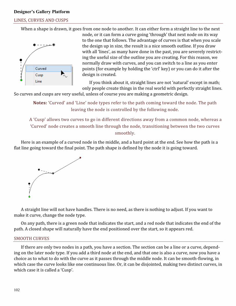
Designer’s Gallery Platform
102
LINES, CURVES AND CUSPS
When a shape is drawn, it goes from one node to another. It can either form a straight line to the next node, or it can form a curve going ‘through’ that next node on its way to the one that follows. The advantage of curves is that when you scale the design up in size, the result is a nice smooth outline. If you draw with all ‘lines’, as many have done in the past, you are severely restrict-ing the useful size of the outline you are creating. For this reason, we normally draw with curves, and you can switch to a line as you enter points (for example by holding the ‘ctrl’ key) or you can do it after the design is created.
If you think about it, straight lines are not ‘natural’ except in math; only people create things in the real world with perfectly straight lines.
So curves and cusps are very useful, unless of course you are making a geometric design.
Notes: ‘Curved’ and ‘Line’ node types refer to the path coming toward the node. The path
leaving the node is controlled by the following node.
A ‘Cusp’ allows two curves to go in different directions away from a common node, whereas a
‘Curved’ node creates a smooth line through the node, transitioning between the two curves
smoothly.
Here is an example of a curved node in the middle, and a hard point at the end. See how the path is a flat line going toward the final point. The path shape is defined by the node it is going toward.
A straight line will not have handles. There is no need, as there is nothing to adjust. If you want to make it curve, change the node type.
On any path, there is a green node that indicates the start, and a red node that indicates the end of the path. A closed shape will naturally have the end positioned over the start, so it appears red.
SMOOTH CURVES
If there are only two nodes in a path, you have a section. The section can be a line or a curve, depend-ing on the later node type. If you add a third node at the end, and that one is also a curve, now you have a choice as to what to do with the curve as it passes through the middle node. It can be smooth-flowing, in which case the curve looks like one continuous line. Or, it can be disjointed, making two distinct curves, in which case it is called a ‘Cusp’.
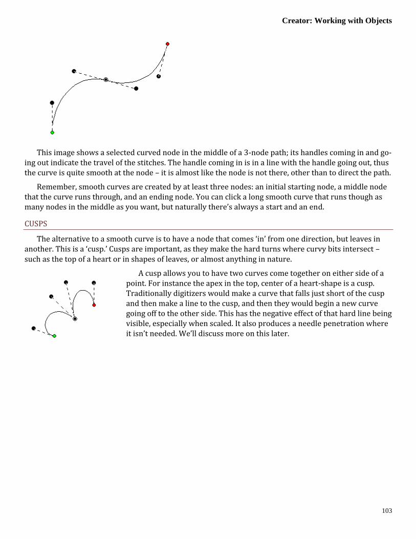
Creator: Working with Objects
103
This image shows a selected curved node in the middle of a 3-node path; its handles coming in and go-ing out indicate the travel of the stitches. The handle coming in is in a line with the handle going out, thus the curve is quite smooth at the node – it is almost like the node is not there, other than to direct the path.
Remember, smooth curves are created by at least three nodes: an initial starting node, a middle node that the curve runs through, and an ending node. You can click a long smooth curve that runs though as many nodes in the middle as you want, but naturally there’s always a start and an end.
CUSPS
The alternative to a smooth curve is to have a node that comes ‘in’ from one direction, but leaves in another. This is a ‘cusp.’ Cusps are important, as they make the hard turns where curvy bits intersect – such as the top of a heart or in shapes of leaves, or almost anything in nature.
A cusp allows you to have two curves come together on either side of a point. For instance the apex in the top, center of a heart-shape is a cusp. Traditionally digitizers would make a curve that falls just short of the cusp and then make a line to the cusp, and then they would begin a new curve going off to the other side. This has the negative effect of that hard line being visible, especially when scaled. It also produces a needle penetration where it isn’t needed. We’ll discuss more on this later.

Designer’s Gallery Platform
104
MINIMAL NODES
Use nodes where the path switches from turning left-to-right or vice versa. And then when turning, place a node at the ‘widest’ point in the turn if you need an additional node. This will yield the fewest number of nodes needed to make the shape. Remember you can add nodes later, or adjust the curves, if you need to refine the shape.
It is good to use minimal nodes to complete your shape, and then go back and edit the curves to get the shape you want. The result will be a nicer object shape and better embroidery. It takes practice, but you’ll find that you can quickly analyze a shape and create it in very few clicks, and then the edits re-quired will be much easier.
OPEN AND CLOSED OUTLINES
Normally in graphics a “Closed” shape or outline means that its start and its end meet up visibly. A shape that is closed can contain stitches within, and can also have “holes.”
CLOSING AN OUTLINE
When drawing a shape for embroidery, you may wish to have the end-point meet up with the start-point without calling the shape “Closed.” For this purpose, there is a button on the tool pane
which lets you specify that a shape is closed or not. Only closed shapes can contain holes.
OPENING AN OUTLINE
You can open an outline by clicking the ‘Close/Open Outline’ button up. You will not see a change in the shape, but you can now move the head and tail nodes away from each other. The tail node will be red.
If you have a node selected when you open the outline, that node becomes the new head/tail of the outline.
POINT INPUT
The Point Input method is the most commonly used method, and for most people, it is the easiest. Click the Point button in the Tool Pane and then start clicking along the line you wish to make.
As you create your shape, you can create curved nodes with a normal left-click, line nodes are made by holding the ‘Ctrl’ key during a left click, and cusps are made by holding the ‘Shift’ key down during a left click.
You can use the ‘backspace’ or ‘Delete’ to remove points you have entered. You can cancel the drawing using the ‘Esc’ or ‘Escape’ key.
When you have completed your shape, you can end it by right-clicking. If you wish to end the shape and also close the outline at the same time, hold the ‘ctrl’ key while right clicking.
While entering points along the outline, you do not need to worry about the Bezier handles – they are created for you using some ‘reasonable’ values. Once you have created your shape, if you want to adjust the handles, you can. Or you can ignore them entirely if you prefer. We’ll talk about that shortly, in the ‘Editing Outlines’ section, subtitled “Working as Spline/Bezier”
BEZIER INPUT
The professional graphics industry has adopted this method of input and it takes getting used to.

Creator: Working with Objects
105
Select the Bezier Input method using the button on the Tool Pane. To begin, click and drag. This will cre-ate an initial Node and a Bezier handle. The next time you click and drag, you will be creating the points needed to complete a Bezier curve section, and also begin the next one.
If you simply click, you will create a flat curve – a line.
To create a cusp, hold the ‘ctrl’ key down when you click and drag.
Right-click to end your input. Holding the ‘Ctrl’ key when right-clicking will close the shape.
FREEHAND INPUT
This sounds like the most fun input method, and it is, but it is far from accurate. The freehand input lets you doodle. You hold the mouse down and drag around. Where you went gets smoothed
out and turned into a curving path. You can click for a line to a point, and then drag along some more. You can drag and release any number of times to create lengthy and intricate paths if you wish.
This is useful in practicality only with the Run stitch type. Drawing freehand on a computer requires practice, and the more fluid your input is, the better the result will be. Do expect to spend some time cleaning up your handwriting!
As with other input methods, right-click to end your input. Holding the ‘Ctrl’ key when right-clicking will close the shape.

Designer’s Gallery Platform
106
Editing Outlines
We have made the editing of outlines work in two modes, Bezier and Spline. To understand spline, imagine something flexible, but with a little bit of spring to it – in the original context a spline was a light piece of wood that could be shaped around things. In this use, it is a line that flexes around ‘Nodes’ on the screen (where you have clicked). The more clicks you give, the tighter the spline will have to bend in or-der to conform to the shape you want.
Bezier lets you adjust the curves using handles, as we have discussed. Now you get to decide how you will perform your edits.
WORKING AS SPLINE/BEZIER
The Spline/Bezier button on the Tool Pane will toggle all the selected objects to either show their handles, or hide them. Remember, if you switch handles off, the outline will change to its au-
tomatic shape, and you may have to add some nodes in order to recover the curves. Spline mode will al-most always require more nodes than Bezier.
If no objects are selected, this button also sets how your next objects will be treated, once drawn. This button also acts as a program preference, so if you choose to always work with Bezier, the next time you run the program this will determine the state in which you start.
SELECTING NODES
You can select a node by clicking on it. You can use the Ctrl key while clicking to select multiple nodes. If a selected node is clicked with the Ctrl key it will be de-selected, as is typical with virtually all computer systems.
You can also select nodes by dragging around them. First, select the object that you would like to edit. Then drag around the nodes you want. When you release your mouse button, the nodes inside the area you dragged will be selected.
You can also operate on holes, carving lines and breaklines in this manner – drag around the nodes you wish to adjust.
ADDING AND REMOVING NODES
Double click on the outline to insert a node. Double click on a node to remove it. If you have a node or nodes selected, you can also use the ‘Delete’ key to remove them.

Creator: Editing Outlines
107
CHANGING NODE TYPES
You can switch the type of any selected nodes by right-clicking, which will bring up a pop-up menu. The node types are Curve, Line and Cusp, as we have discussed. Remember that a curve will allow stitch-es to pass through it without forcing the needle to stop at the node, but by necessity of the shape, lines and cusps will cause the needle to land on those nodes.
MOVING NODES NEAR INCLINATIONS (LEVEL 2)
Sometimes an inclination line will be made very near a node. If that node is moved so that the inclina-tion line is left in empty space, the incline will be removed automatically. We suggest you adjust your out-lines first, then go back and add and adjust your inclination lines.
RECONSTRUCTING OUTLINES (LEVEL 3)
Sometimes you will obtain a file that claims to be in vector form, but is actually an auto-traced image. These are common from clip-art websites, even the big ones. This leaves a series of nodes touching each other as they go around the outline. You can use the menu ‘Create->Outline->Reconstruct Outline’ to sim-plify the artwork.
Left: before. Right: After Reconstruct Outline
SPLINE MODE EDITING
Spline mode has the ability to insert and remove nodes to adjust the shape. If the curve is too far away from the outline you want, simply add more points on the outline where the shape you have is ‘most dif-ferent’ or furthest away from the artwork.
It is often best to begin with minimal nodes in the outline, only basically representing the shape you are drawing. Then, go back and insert only the nodes that are needed to pull the outline into shape. Doing it this way, you will use a minimum of nodes.
Why use a minimum of nodes? The stitches being generated have to look at all the nodes on your shape. If you insert hard nodes or cusps, the needle will penetrate at those nodes, so you get less desira-ble embroidery and an increased stitch count. Another reason to use minimal nodes is for editing purpos-es. Suppose you test sew your design and realize you need move overlap for registration issues – the few-er nodes, the easier and faster the edits can be accomplished.

Designer’s Gallery Platform
108
BEZIER MODE EDITING
Editing paths with Bezier handles exposed is not hard, and is very intuitive once you get past the first few minutes or so.
Editing is accomplished by dragging the handles, which adjusts the curve as you drag. You can also drag the outline itself into place, which will adjust the handles for you. When dragging the outline, the closer you are to a node, the more that node’s handle will be adjusted, rather than the one you are farther away from. Because this can make your handles go ‘wild’ we do not let the outline drag if you grabbed it within 5% of the ends of the outline in either direction. It is best to grab the curve somewhere in the mid-dle and drag it, then adjust the handles to perfect the shape.
Note: Sometimes art will have the handles ‘hidden’ under the nodes. Drag the outline and the
handles will move, exposing them so you can drag them around as needed.
Here’s a step-by-step example of making use of minimal nodes while drawing, and good use of re-shaping: Make a heart, starting at the bottom, using all Cusps (Shift key). You only need four points! Ctrl-right-click to close the outline:
Next, hover your mouse over the curve in between the top left two points as shown, and drag the curve up. You will see the shape beginning to appear. Repeat the drag for the other side. In the example above, we’ve made the sides smooth too. Do any editing desired for the overall image, and you have a low-node-count shape that looks great!
There are also some tricks which we would like to share.
Trick 1: A favorite old movie of ours, Ghostbusters has the line, “Don’t cross the streams!” In the movie, it implied that ‘Bad Things’ could happen. What we’re saying here is, “Don’t cross the handles.” It’s not that you cannot cross the handles – you can – but certain object types will not understand what it is you’ve done. So we discourage it.
Trick 2: Another thing to consider is that the handles should generally be in the direction of the travel of the path. If you have your handles pointing away from the travel of the stitches, then the stitches may do a “Two-Step” which you might not want to happen.
Trick 3: Sometimes you will inadvertently wind up with a handle hidden under the node it is attached to: it is a handle with no length. You can recover these by mousing-down in the middle of the curve and dragging the outline, which reorients the handles for the curve you are dragging. Once the handles are exposed, you can position them as needed.

Creator: Working with Outlines
109
Trick 4: Use nodes where the path switches from turning left-to-right or vice versa. And then when turning, place a node at the ‘widest’ point in the turn if you need an additional node. If you have extras, you can delete those and adjust as desired.
Working with Outlines
HOLES
Holes or ‘voids’ can be added to artwork for stitch types that use them such as Fills.
In order to be able to add a hole to a shape it must not only appear closed, but actually be closed. You can tell by looking at the ‘Close outline’ button on the Tool Pane when the object is selected. If the button appears depressed, the shape is closed. If not, you can click the button to close the shape.
Not all stitch types allow holes. When it is allowed, the ‘Add Hole’ button on the Tool Pane will be en-abled. You can push this button and then begin drawing the hole. Right click to complete your drawing as with any drawing operation. To add another one, simply click the button again. There are no limits to the number of voided areas (holes) that can be on a shape.
The hotkey for adding a hole to the currently selected object is ‘o’.
If you have drawn several objects, or used path operations to create them and you want to combine holes from multiple objects, select all the objects and use the menu Create->Outline ->Combine Holes.
Holes can be removed by selecting a node on the hole and using the right-click pop-up menu entry, “Delete Hole”.
Similarly you can separate the hole into a new object, as an outline, with the right-click pop-up menu entry, “Separate Hole.”
If you have multiple objects with original art that has holes, but you would like to separate them out as individual objects, use the menu Create->Outline->Separate Holes.
CONNECTING OPEN LINES
When you have two or more lines that should be connected, use the menu ‘Create->Outline->Connect’ to make them into a single line. While you are drawing, it can happen that you end the drawing before the outline is fully created. You can simply create the rest of the line as a separate object, then select both and connect them.
When connecting lines, the head and tail of the first line in the sequence are preserved, and thereafter the lines that are being connected to it will be reversed as needed to ensure the nearest connecting point. You do not need to have your line endpoints adjacent, as a connecting line will be added for you if needed.
REVERSING POINT ORDER
When you create a line, there is a point where you started and a point where you ended. If you wish to reverse the direction of points on the line, use the menu Create->Outline->Reverse Points.
Generally, the outline order is not very important for the creation of stitches. You may, however want to use this when working on connecting shapes you have made.

Designer’s Gallery Platform
110
BREAK ACROSS POINTS
You can select two points across a closed outline and break the outline into two using the context menu option ‘Break across’. This is sometimes useful in logo or promotional designs, where you have original shapes, but want to separate them and insert a word or other design element in between.
BREAK AT POINT(S)
If you have an open shape selected, with one or more nodes in it selected, the context menu option, ‘Break at point’ will split the object into multiple objects.
CONNECT TO HOLE
Sometimes you’ll need to turn a shape with a hole into a continuous outline, such as to make a satin stitch. To accomplish this, select two near points, one on the outline and one on the hole. Then use the context item, ‘Connect to hole.’ The hole is now part of the outline, as shown:
Entry and Exit
While not directly used in defining a shape itself, there are En-try and Exit points that accompany outlines once a stitch object type has been assigned.
These Entry and Exit points indicate the preferred location of the beginning and ending of the stitching process. In the illustration, the stitching would begin at the green handle on the left, and finish up at the red handle on the right. You can drag the handles around an-ywhere on the outline. You cannot drag them to a hole, if the shape has one.

Creator: Entry and Exit
111
There are some object types where the stitching follows an algorithm that comes back to a single point. Those object types are noted in their respective sections. Entry and exit points are used to limit the number of jump stitches in a design. By having the objects end and begin at near-most points, the transi-tion stitch between the objects is minimized.
The Entry point on an object is where the stitching will begin, and Exit is where the stitching will complete. The purpose of adjusting the entry and exit is to minimize (or eliminate) traveling runs needed to move from one object to the next. This also lowers the stitch count.
Note: Usually you will want to set the Entry and Exit points after you have sequenced your
objects.
Most stitch generation has the availability of adjustable Entry and Exit points, although some only use the Exit such as Stippling, where stitching is continuous.
Entry and Exit adjustments are usually not noticeable in the resulting stitches except for Runs. Runs by definition have styles such as Single, Double, Bean, etc. When you have a single run enter and exit at the same point, you are going to have a double-run result. The exit handle forces the stitches to run to the exit, over top of what’s been stitched. This can be handy when creating redwork or running-stitch designs as you may set the Exit Handle as needed, and not worry about changing the property to a double.
MANUALLY SETTING ENTRY AND EXITS
Entry and Exit on a stitch object are controlled by the green (Entry) and red (Exit) handles on the out-line of the object. Drag the handles to the point on the outline as desired. Generation of stitches is auto-matic.
AUTOMATIC ENTRY AND EXIT
Use the menu Create->Auto Entry/Exit to set the Entry and Exit handles on selected objects. The ‘Au-tomatic’ process looks for the nearest points on the objects if they don’t touch, or to a point where they touch, if they do.

Designer’s Gallery Platform
112
Magic Wand
The Magic Wand is a tool used to create outlines from bitmap images. There are two styles – a wand for filled areas, and a wand for lines. The Line Wand tool is available in Level 3.
When you turn on the Magic Wand, you can click on the backdrop image and the Wand will look at the color where you clicked, find all pixels (dots) around it with a similar color, and then make an outline out of all of those similarly-colored pixels. The shape that a Magic Wand creates will not be as clean as one drawn by hand, but they are fully editable, and can be an effective way to get started on some simple pro-jects.
Note: When you like the wand result, right-click to end the wand to keep what you’ve made. If
you click the Wand button again, or hit the ‘Esc’ key, you cancel the operation.
SENSITIVITY
Because images differ in quality, when you click on the wand, the Sensitivity controls will appear. A low number of sensitivity means the pixels it is looking for will be very similar to the one on which you clicked. If you have an image with a mottled texture, for instance a piece of scanned fabric in the picture, you can make the sensitivity large, for example use 150, and the outline will be expanded to include more pixels to get a better outline.
As you adjust the sensitivity the wand will re-wand where you clicked automatically. You do not need to click again.
Important: When you like the wand result, right-click to end the wand and keep what you’ve
made.
REPEAT CREATION
The wands will create as many objects or holes as you like. Once your sensitivity has been adjusted and you have an outline you like, simply click the wand again in another area to begin making a new ob-ject. Right-click to end object creation once all objects have been wanded.
Expand the Object View to watch the objects get created – sometimes a higher sensitivity will result in fewer objects or outline nodes, which is desirable. Other times, higher sensitivity can add ‘noise’ in the edge, or even fail to find a shape at all when the outline and background are similar.
FILLED AREAS
The first wand button creates an outline around areas filled with a consistent color.
You can also use the wand during an ‘Add Hole’ operation.
Normal graphic fills, such as those from a cartoon image will not need a high sensitivity to the color used. You can reasonably use the default number. If the image is scanned from a print, you might need to increase the sensitivity a little. Try different levels to see what you get. Note that some large images with a high value for sensitivity can take longer to wand.

Creator: Magic Wand
113
LINE AREAS (LEVEL 3)
The second Magic Wand is for line drawings and line areas in a cartoon-style image. The color you click on has all of its pixels gathered and thinned to make a running-stitch object. The line drawing may be very complex, and the Line Wand will create as many objects as it needs to in order to stitch around the entire design doubly. This is useful for automatic outline or redwork designs. The Line Wand will set all the Entry and Exits and create a double-run design ready to sew.
The objects that are created also have Styles used. You can adjust these styles, thus adjusting the style of the result. Please refer to the Styles section for details.
To further explain; let’s examine a simple ‘T’ shape that might represent any ordinary outline draw-ing. The Line Wand will find a starting point, run to the ‘T’. Now it has to go both directions in order to sew the entire shape. To do this, it will run out on one side first. Then run back. This process repeats for the second side. Now that this part of the path is complete, it can return to where it started. In this way, the entire design has been stitched over twice.
If you don’t want the entire design branched in this fashion, the objects created are editable – you can do what you like. Also, the objects have styles named for what they are doing within the path. By chang-ing objects labeled ‘Run’ you are changing the run out – not anything with topstitches. Change the ‘Dou-ble’ for branches that are open-ended – they run out and back. Change the ‘Return’ for topstitching as the stitching comes back over itself.
LINE-WANDING GRAYSCALE IMAGES
Some bitmap images will be like an old black-and-white television image, and we call those grayscale. When you load a grayscale image, the chances are good that the image will have lines that look nice and clean, but are really all sorts of gray variations, like a pencil drawing. Grayscale images are fine to work over, but if you plan to use a magic wand line input you may want to save the image as a Black and White (1-bit) image, if you have an image-editing program such as Paint.
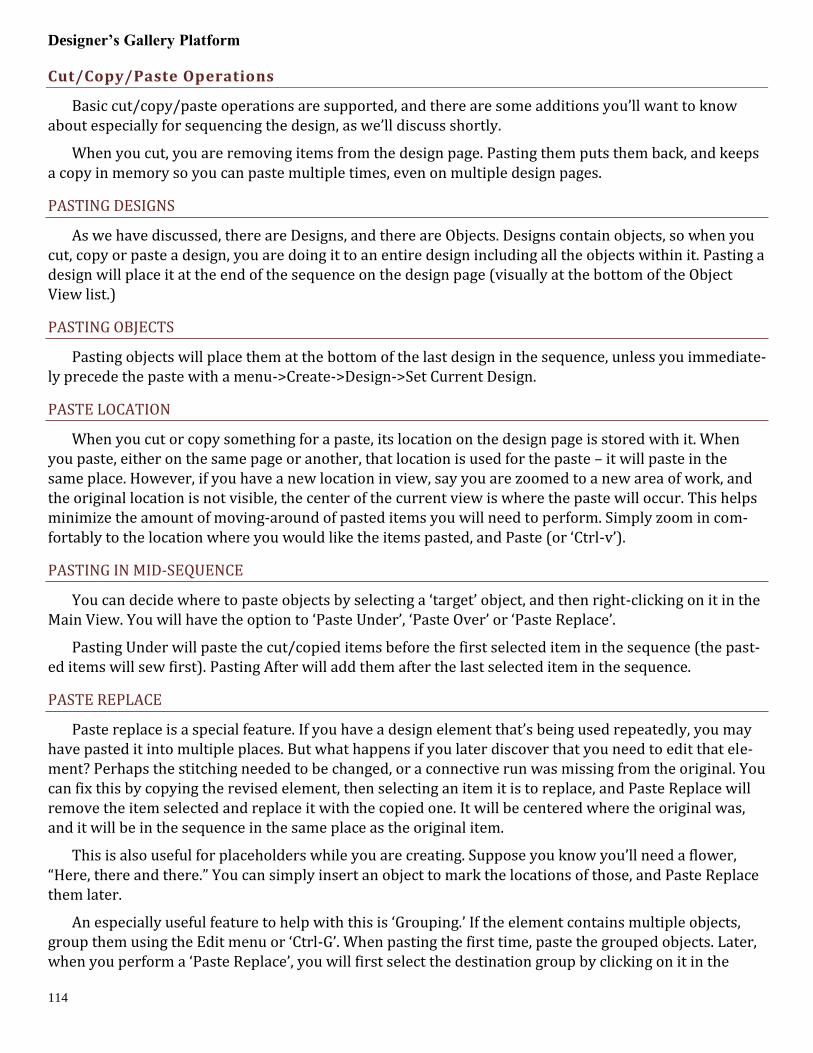
Designer’s Gallery Platform
114
Cut/Copy/Paste Operations
Basic cut/copy/paste operations are supported, and there are some additions you’ll want to know about especially for sequencing the design, as we’ll discuss shortly.
When you cut, you are removing items from the design page. Pasting them puts them back, and keeps a copy in memory so you can paste multiple times, even on multiple design pages.
PASTING DESIGNS
As we have discussed, there are Designs, and there are Objects. Designs contain objects, so when you cut, copy or paste a design, you are doing it to an entire design including all the objects within it. Pasting a design will place it at the end of the sequence on the design page (visually at the bottom of the Object View list.)
PASTING OBJECTS
Pasting objects will place them at the bottom of the last design in the sequence, unless you immediate-ly precede the paste with a menu->Create->Design->Set Current Design.
PASTE LOCATION
When you cut or copy something for a paste, its location on the design page is stored with it. When you paste, either on the same page or another, that location is used for the paste – it will paste in the same place. However, if you have a new location in view, say you are zoomed to a new area of work, and the original location is not visible, the center of the current view is where the paste will occur. This helps minimize the amount of moving-around of pasted items you will need to perform. Simply zoom in com-fortably to the location where you would like the items pasted, and Paste (or ‘Ctrl-v’).
PASTING IN MID-SEQUENCE
You can decide where to paste objects by selecting a ‘target’ object, and then right-clicking on it in the Main View. You will have the option to ‘Paste Under’, ‘Paste Over’ or ‘Paste Replace’.
Pasting Under will paste the cut/copied items before the first selected item in the sequence (the past-ed items will sew first). Pasting After will add them after the last selected item in the sequence.
PASTE REPLACE
Paste replace is a special feature. If you have a design element that’s being used repeatedly, you may have pasted it into multiple places. But what happens if you later discover that you need to edit that ele-ment? Perhaps the stitching needed to be changed, or a connective run was missing from the original. You can fix this by copying the revised element, then selecting an item it is to replace, and Paste Replace will remove the item selected and replace it with the copied one. It will be centered where the original was, and it will be in the sequence in the same place as the original item.
This is also useful for placeholders while you are creating. Suppose you know you’ll need a flower, “Here, there and there.” You can simply insert an object to mark the locations of those, and Paste Replace them later.
An especially useful feature to help with this is ‘Grouping.’ If the element contains multiple objects, group them using the Edit menu or ‘Ctrl-G’. When pasting the first time, paste the grouped objects. Later, when you perform a ‘Paste Replace’, you will first select the destination group by clicking on it in the

Creator: Grouping Objects
115
Main View and perform the ‘Paste Replace.’ This selects the entire group and will remove that entire group when you Paste Replace.
Grouping Objects
Objects can be grouped so that when you select one in the Main View, all will be selected together for operations such as Move, Rotate, Mirror, Cut/Copy/Paste, etc.
Use the Edit menu->Group or ‘Ctrl-g’ for this.
Note: When items are grouped, they are still individually selectable in the Object View, and
can be edited singly if selected.
If you have a design selected when grouping is performed, the design is part of the group. This means sequencing and copy/paste operations will be done at the design level. If you want all the objects from a design, but not the design itself, make sure to check the Object View to see that the design is not selected.
The Edit menu->Ungroup (Ctrl-u) can be used to ungroup objects.
You can group selections that contain sub-groups. Ungrouping will not ungroup the sub-groups – those will have to be ungrouped with a separate ungroup command.
Sequencing
The sewing order of the design is very important. You don’t want your design to sew randomly all over the fabric. It will leave jumps, or have increased trims, or worse, increased color changes, and if you sell designs, your customers won’t be happy.
There are ‘best practices’ for sequencing on different embroidered goods, most notably hats. If you’re creating a design for a hat, you’ll want to attempt to sew from the center outward. This helps keep the fabric in place and flat in the hat frame.
For regular designs, it can often be useful to have stitching work the edges of the design first, in effect anchoring the stabilizer, then work from the center out.
Think about how you would like the design to sew. You’ve probably watched hundreds of designs stitching out, and you can use that experience to help you decide what to sew in what order. Things that connect are pretty easy to figure out – you want them to sew without jump stitches, usually. If you are new to embroidery, we recommend you spend some time embroidering so you can get used to the stitch-ing process. If you can look at a complete design, figure out what object types were used to make it, and predict which objects will sew in what order, then you are ready to take on sequencing.
Work on the sequence on a per color basis. There is always a trim when the machine goes to the next color, so imagine your machine working one color at a time. And yes, there are times when it is necessary and even a good idea to revisit a color – you don’t have to put all your colored objects together. Layering and Shading are good reasons to separate a color into sections with different colors in between.
Once you have a sequence in your mind, you’ll need to adjust the objects to match. And for that, you’ll need to know how to change the sequence your design.
THE OBJECT VIEW
The Object View shows you the sequence of your objects in the design. You may have a lot of objects for a complex design, and that’s normal. If the design can be broken down into separate designs them-

Designer’s Gallery Platform
116
selves it may be helpful. For instance if you have a picture of a flower and a butterfly, you might make them separate designs on the page, and create them separately.
When you right-click on an object in the Object View, you get a pop-up menu which lets you move de-signs in the sequence. This is often handy for simple or small moves.
You can also select objects in the Object view and drag them to new positions in the sequence. The items being moved will go into position immediately after the item you release the drag upon.
Remember that designs operate at the root level of the Object View. If you move a design into the middle of another design, you will get three designs – the first, up to the point where you pasted, the one you pasted, and then finally the rest of whatever the first design contained.
If you have a Design selected, and not just objects, the Design itself will move. If you wish to move ob-jects only, make sure you do not have the Design selected.
You can drag all the items out of a design, leaving an empty design. If this happens, you can select the design in the Object View and delete it using the Delete key or the Edit menu ‘Delete’.
When items are locked or hidden, they are always still selectable in the Object View, so be aware of inadvertently selecting locked objects.
CUT/PASTE SEQUENCING
A simple and effective method of sequencing is Cut and Paste. You can Cut any selected objects and Paste them at the end of the sequence, or before or after any other object.
The normal Paste (Ctrl-v key) will paste the objects at the end of the design.
Using this method, you could drag or click-select objects, cut, paste, and move on. You are sequencing the design by the order of your cut/paste operation.
SEQUENCING BY COLOR
Sometimes you have made a design, perhaps with a lot of copy/paste operations, and you wind up with objects of different colors out of sequence. You may want to sequence them by color before adjust-ing the sequence further. To accomplish this quickly, select the objects and use the menu Create->Auto Seq. by Color.
AUTOMATIC SEQUENCING
A fast way to get objects sequenced (although not a perfect method) is to automatically sequence them. This requires that you first decide on what you want to sew first, and what you want to sew last in a set of objects. Manually sequence those two objects so they are the first and last in that whole set of ob-jects. This gives the program something to use as a starting point.
Next, select the set of objects, including the first and last. Use the menu Create->Auto Sequence. To se-lect the set, you could drag around them in the Main view, or Ctrl-click them in the Main view, or click the first one in the Object Tree, and shift-click on the last one in the Object view. See the Object view section of the program help for more ways to select.
The program attempts to minimize the travel among objects so that connective runs or jumps are shorter or eliminated. This form of sequencing is not as good as what your brain can do, with a little thought, but it is a reasonable approximation, and sometimes a helpful starting point for your manual se-quencing process.

Creator: Sequencing
117
CLICK SEQUENCING (LEVEL 2)
Similar to the Cut/Paste sequencing method, you have the option to perform the same thing with sin-gle clicks. The Sequence Mode button on the Tool Pane begins this mode. Click on an object. That object and anything grouped with it will be moved to the tail of the design. Click on the next object and the same thing will happen. Thus if you click on all the objects, starting with the one you want to sew first, and end-ing with the one you want to sew last, you will have sequenced the entire design.
To exit the mode, click the button again or use the ‘Escape’ key.
You do not need to sequence the entire design – you can sequence the parts you want. Then if needed, select what you have sequenced, cut the objects, select a target object and perform a ‘Paste Before’ or ‘Paste After.’
SEQUENCE BY ASSIGNING STITCHES
If you have imported artwork as a vector file, that artwork is flagged by the program as ‘newly im-ported art’. With this art, the program assumes the sequence is not designed to sew.
As you assign stitches to objects, the program will begin sequencing the objects to the end of the de-sign. The purpose of this is to allow you to perform both jobs simultaneously; assigning stitches and cre-ating the sequence that the objects will be sewn.
If you do not want this to happen on the imported file’s objects, simply select it in its entirety and click ‘Line’. This has the effect of clearing the ‘newly imported’ state.

Designer’s Gallery Platform
118
Ties and Transits
Ties are stitches that form knots in the embroidery both allowing for trims and to pull up the bobbin thread when stitching has just begun. We refer to these as entry ties and exit ties, but some may call de-scribe it as “tying in” and “tying out.”
In each object property page you are given the opportunity to explicitly set ties. Click the button with the bow tie icon on it.
The ties are automatic and basically look in the direction of stitching to find an innocuous angle, then stroke a few stitches forward and back – enough to bind the stitch and bring up the bobbin thread. For most items, even if a tie-in misses a stitch in the case of a stubborn bobbin thread, the underlay will have enough stitches to spare.
You can of course add a few manual stitches, if you choose, with a separate object, but generally the automatic ones work.
Transits are what happen when the embroidery moves from place to place – often between objects. Rather than adding transit properties to each object, the overall design page has transits set in the Pro-gram Preferences on the Files tab. When performing commercial embroidery, small movements between objects can have a tightly nested run, which buries the stitches, and no trims are desired because they slow down the process. For home and hobby embroiderers the tie/trim/tie approach seems to be univer-sally approved. To accommodate these differing viewpoints, the preferences “Run when jumps are small” and “Ensure ties surrounding jumps” allow for automatic negotiation of the transits.
“Run when jumps are small” allows for two nested 1.5mm stitches – or a total 4.5 mm between ob-jects before the transit will allow a single whole stitch.
When the stitch exceeds this value, and “Ensure ties surrounding jumps” is set, ties are ensured in both directions, and a trim command is sent out. Some machines have lower limits to the length of a movement before they will trim, often 5mm, but in case the user wants to hand-trim the design, the ties are there to prevent the embroidery from unraveling.
A difference in style: Most hobby embroiderers will trim everywhere they can. However,
commercial embroiderers wouldn’t nest the runs if the result was something they got
complaints about – they don’t. Only an embroiderer with an eye for it would notice a few
nested stitches, usually between lettering. So you might just want to save yourself some
effort, and turn the transit options on.

Creator: Default Style
119
Default Style
Styles allow for repeated use of properties on a given type of object. There is a QuickStyle button on the top, right of each object property page. When an object has been assigned a style, that style will be highlighted in the style list, shown on the Style properties for the object. If an object was given a style, but then modified from that style, its style name will have an asterisk (*) following the style name.
When you begin creating objects having just run the program, the default styles are being used, called “Normal.” These have been tested to be reasonable for all-around conditions, but naturally properties ex-ist for a myriad of reasons.
If you click on the ‘Normal’ style it will reset the object(s) to that style. Keep in mind that all proper-ties will be reset.
Line Objects
A line is simply a shape. It has no stitches applied to it. When you bring in vector files, or Tru-eType they are lines. As artwork without stitches, they have no properties other than color.
Manual Objects
Manual stitches are straight lines, with the needle dropping at every node. Manual objects are typically used in the creation of Motifs, but occasionally you may need a manual stitch for a tie or
something really small, where runs will not calculate well – for example when adding a single stitch to cross a satin column when creating a Celtic knot as previously described.
To protect the user from resizing the design and obtaining a very large stitch, manual stitches have a property that limits the maximum length of an individual stitch.

Designer’s Gallery Platform
120
Run Objects
Run stitches are the heart of any design. You could, with patience, create virtually any design with run stitches. There are a lot of variations to them as well.
A basic single run is how your stitches travel from one point to another. The run has a length for each step. With curves, however, the stitch length may shorten when needed to go around a tight turn. This is described as “chord gapping” in math parlance. It creates a run that is more faithful to the shape.
When runs encounter curved nodes on the path they are following, they do not need to cause a needle penetration, but with cusps and straight lines, they do, otherwise the stitches would not match the out-line. So if you see a needle penetration that makes the stitches look uneven in length in your run, go back and check for an inadvertent line or cusp point.
A double run is one that makes its path like a single run, but then reverses its steps to return to the starting point. For this reason, when you switch a single run to a double, the Exit point will be reset to match the starting point for you automatically.
A Bean stitch is like a traditional sewing machine’s triple-stitch. The needle makes two steps forward, and one back. This provides a heavier stitch that stands out better against a pile fabric. The bean stitch also has an option to repeat the stitch (in place) up to 9 times, which can make a heavy hand-sewn look. If you use this option, we recommend a longer stitch length so that the fabric/stabilizer can support the tension created by that many stitches.
The chain stitch is homage to heirloom hand sewing and forms a pretty effect that looks nice when combined with traditional design, especially floral.
Like the chain stitch, the Back stitch and Stem stitch are also traditional heirloom stitches. As you se-lect these stitches, you will see properties appear for them.
The Sashiko stitch attempts to emulate the Japanese hand sewing look. The word Sashiko translates to “Little Stabs” and describes the short interval between stitches. To accomplish the look, this run creates a small step forward, followed by a multiple-pass stitch that is a little bit thicker. At arm’s length, the effect is rewarding. Used in the traditional colors of white thread on indigo fabric, the stitches resemble grains of rice laid end-to-end.

Creator: Motif Run Objects
121
Motif Run Objects
Motif runs use patterns of stitching along a path, much like the decorative stitches of a sewing machine.
When you initially set an object to a Motif run, it will only have normal run stitches in it. You will need to add a motif to the run. Click the ‘Add’ button and the Motif Selection window appears.
Once you have selected a motif, for the run, the run will re-generate with the motif. The motif will also appear in the list box in the bottom of the property page. You can add as many motifs as you like, and they will be added to the sequence in the order that you add them. Each motif has its own properties that you can adjust. Select the motif in the list to adjust its properties. You can remove a selected motif with the ‘Remove’ button, next to ‘Add’.
The height, width and rotation of the motif are set as their name implies. The mirror buttons will flip the motif in the sequence. You might want to have two copies of a motif ‘facing each other’. This can be
done by adding the motif twice to the list, and then flipping one. The ‘Gap’ of the motif indicates that some amount of space should pre- cede the motif, after the previous one.
The Motif Scaling button allows you to incrementally adjust the size of each motif in the run. This makes for a decorative effect. If you increase the size, start with the motifs all at a regular or small size in the Height and Width fields. Then you can add a few percent of size for each pattern that is displayed. If you want to create your run with motifs decreasing in size, start with the motifs’ height and width as large as you will want, and decrease will make each successive pat-tern smaller. This may take some trial and error to get the result, but the effort is worth it, especially if you want to run ‘center-out’ and have motif run scaling in both directions.

Designer’s Gallery Platform
122
Satin Border Objects
The satin border is one of the most versatile and easy-to-use stitch types. The shape is a simply line, with no need to worry about inclinations. The border follows the outline and has a width, much
like a sewing machine. As a satin stitch, however, there are numerous properties available for the satin border.
At the top of the property page there are separate buttons to show the top stitching, underlay and ap-plique properties. The top stitching is composed of the width and density of the stitch, along with any variation in the stitch width which gives a simple way for a satin border to approximate a column, but without inclinations.
The Style of the border topstitch will have a smooth satin or pattern, a split satin which divides itself into columns, or a feathered-edge stitch.
You can also adjust the line and nib style for open path outlines. The line style varies the width over the length of the outline in a manner according to the image displayed in the list box.
The nib is the shape of the endpoint. You can use the normal squared-off satin end, or add a curved or tapered tip to either end for a more finished look without the use of a column.
The border can have applique steps added to it, very much like the normal Applique object type, the difference being that when using the satin border type you have much more control of the topstitch itself.
Please see the Satin Column section for information about the patterns and underlay.
Tip: When using a wide border, use a split (value of 2) with no reverse pattern to help
prevent the stitches from looping, while still maintaining the look of a satin.

Creator: Satin Column Objects
123
Satin Column Objects
Satin columns are versatile objects, and this property page allows you to use the column in a few styles. “Normal” satin stitches are what you almost always think of with satins; they go left-to-right
and back again, making a smooth, narrow, continuous stitch. But you also have the option for Contour and Fringe stitching styles available.
DENSITY
Satin columns are one of the most-used stitches, and they have a lot of properties available. The most important of which is the density. Remember that density is measured in stitch points, which are tenths of a millimeter. The bigger the distance, the lower the density. Normal density for satin columns is 4 points to 5 points unless a fine thread and tightly woven fabric are used. Often, the 5 point density is pre-ferred as it will not push the fabric around as much, and still provides nice coverage.
PATTERN
When choosing the patterned topstitch, a normal smooth satin is the default, however you can adjust the patter to appear like a fill pattern that curves with the stitching. Each pattern can have its stitch prop-erties adjusted. Stitch Length in the pattern relates to the size of the pattern that is made. If you make your pattern too wide, it will not be visible unless the satin itself is very wide. Here you can see how a sat-in pattern will turn with the stitching:
The Edge Pad is a means of protecting the edges of the stitches from have excessive needle penetra-tions which can pull on the fabric and pucker.
When patterning, the needle penetrations can lie next to one another causing the fabric to lash or even cut. If this is a danger for the fabric being embroidered, set the “Reverse” to “None” which means the pattern will only occur on every other stroke of the satin. The pattern effect will be lighter, but the em-broidery will be better and the fabric will not have as many cuts.
The pattern of the satin also has compensation and gradient properties. Please refer to the Fill Pattern section of Fill Objects for images and further description.
FEATHERING
Feathering the edges of satin columns is a good way to simulate animal fur. Overlap multiple layers to make a more realistic appearance. In this example, three satin rings were set with feathered edges. The rings sewed outer-to-inner, and overlap slightly.

Designer’s Gallery Platform
124
SPLIT
A split stitch in the column simply means that the needle will land in rows, lengthwise along the col-umn. You can set the number of split columns, the minimal stitch value (to avoid fabric cuts) and you can avoid the reverse stitch pattern, which helps preserve the look of the satin column. Here is a column split into three:
UNDERLAY
Satin stitches are good at covering the fabric, but they have challenges, especially along the edge, where tightly placed dense stitches can penetrate the same hole in the fabric or even cut the
fabric. You may have sewn, for example a knit shirt, and had the edges of satin stitches create holes in the fabric. For this reason a parallel or zigzag underlay is often used. It provides coverage while pulling the fabric at slightly different angles and that can allow the top stitching to have reduced density.
Satin also has the issue of tension. Short stitches in the same direction, laid next to each other, builds up stress in the fabric, gathering it in toward the middle of the satin stitch. This can cause registration is-sues with subsequent stitching. This can be managed by binding the stabilizer to the middle of the satin with a center run, or a pair of edge runs which travel just inside the shape. The edge runs also have the added benefit of lifting the edges of the satin up, out of the pile of the fabric. For these reasons it is not uncommon to use a medium density satin with a lot of underlay.
In the underlay properties, the “Edge Run” will create runs on either side of the satin, just inset by an amount controlled by the Inset field on the property page. The inset for the edge run is usually is set to

Creator: Satin Column Objects
125
fall just inside the stitching – perhaps a half-needle with or slightly more, which allows some relief around tight corners. The stitch length of the edge run is also adjustable; use smaller stitches for tight, narrow columns and longer ones if you want to reduce the stitch count, or are worried about cutting the fabric. The default is usually sufficient though.
The density of the parallel and zigzag underlay is adjustable for increased coverage. Sometimes it is better to have a higher density underlay (0.8 – 1.2mm) and a lower density top stitch (0.8mm) so that the coverage is solid, but the pull on the fabric is reduced, which helps with registration issues (eliminating gaps between stitched areas).
The ‘Freestanding’ underlay creates a mesh under the satin, similar to the freestanding background object type. This is useful when making Richelieu bars or satin shapes that will be stitched on wash-away stabilizer. When using the ‘Freestanding’ option, you do not need the other options, so you can leave them off. The Length, Inset and Density properties do not apply to the ‘Freestanding’ option.
CONTOUR (LEVEL 2)
Checking the ‘Contour’ button on a Satin Column will arrange the stitches to run opposite to the incli-nations, rather than parallel to them. The density is maintained throughout the column, even if the col-umn widens and narrows, as the program will automatically adjust the number of rows as the width changes. Contour 2 will provide more of a ‘fill’ effect as areas widen and narrow, whereas Contour will have varied density across the shape as it widens.
FRINGE (LEVEL 2)
The Fringe stitch is a unique stitch that allows you to create what some call “3D Embroidery” by cut-ting the bobbin threads under the satin, which frees up one side of the stitching to come up and away from the fabric.
This Fringe stitch lays a run down along the edge of the satin first, and then places the satin over top with extra needle penetrations causing the satin to anchor itself to the run. It finishes off with a top stitch run to anchor it all together. This method allows you to have fringe effects in embroidery without the need to anchor the stitching down with a fill, as has always been the case.
Note: When setting fringe options, left and right are subjective, and if you edit the outline or
inclinations after making this setting, those could actually switch.

Designer’s Gallery Platform
126
Satin Column Input (Level 2)
Now that we have covered outline basics, it’s time to discuss Satin Columns. Satin Columns have stitches that go across the shape from left to right forming a smooth, possibly curving, filled area. Satin columns are also referred to as “Turning angle fills” sometimes. Satins are generally the second most im-portant stitch type you will use, after Runs.
Because we tend to think of satins as going ‘left-to-right’ or ‘side-to-side’ there are special input meth-ods for them accommodate this.
Satin columns are special because in addition to the shape itself, you’ll need to add incline lines to get the column of stitches to curve nicely. The incline lines are the direction the stitches will lay on the fabric.
INCLINE LINES
Before we can discuss the input methods of satin columns, we need to go over incline lines.
When you have a shape drawn that will be a Satin Column, you will need one or more incline lines, al-so called, “Inclinations.” When you first draw the shape, the program attempts to provide a satin stitch automatically, based on the shape. If this is acceptable, you can skip adding your own.
The incline lines input can be started using the ‘i’ key or the Inclines button on the Tool Pane. To add an incline line, simply begin on one side of the shape by clicking down, and then drag the mouse across the shape to the other side. When you release the mouse button you will have added an inclination line to the shape. You can repeat this drag operation to make as many incline lines as the shape requires. When you are finished, simply right click to exit the mode.
How many incline lines do you need? That is a great question, and like a haircut the answer lies in the form of a question, “How does it look?” Simple lines of satin stitching might only need one or two inclines. But if you curve around, you’ll need one whenever you make a quarter-circle, or whenever you want to switch from turning left-to-right or vice-versa.
Generally, start with a pair of inclines at the ends, and at least one in the middle. As you add inclines, you will see the stitches change. You can stop anytime you are happy.
If you make a mistake, you can exit the Inclines mode, and then simply drag the endpoints of your in-clines around. You can also drag one of the points to the opposite side to remove the incline. You can also go back and add, remove or move the inclination lines at any time, which is handy if you decide you need to edit the shape later.
When a shape turns, one side will be longer than the other. This means that one side will have its stitches closer together than the other. Another way to say this is that the density (stitches per inch) in-side the turn is higher. When the satin stitch is created, it is given a specific density to maintain – and that is on the outside of the turn, not the inside. The program will do things on your behalf, such as short-stitching, to minimize the impact of the increased density on the inside of turns. But you can also help by looking at what is going on, and making changes to the inclinations so that the density increase is mini-mized.
Tip: When turning around a tight corner, you might want to begin ‘leaning’ into the turn,
which helps the stitches go around with less bunching:

Creator: Satin Column Input (Level 2)
127
Another issue to look at when adding, or adjusting, inclinations is smoothness of the change in angle. You don’t want your inclinations to be ‘wobbly’:
When going ‘around’ a large curve, imagine a center point, and incline as if there were rays radiating from that center point:
The smoother you change the angle in your satin objects; the smoother the sewn result will appear.

Designer’s Gallery Platform
128
INCLINES AT ENDS OF SATINS
Satin objects are like any other – they have a shape. It is the inclination lines that define that shape as a satin. This has some noteworthy effect on the ‘ends’ of the shape, because, naturally, shapes don’t have ends; people perceive them though.
In the picture below, what do you see?
Perhaps a rudimentary smile? And what are the ‘ends’? If we asked a thousand people, they’d all tell you the same thing. The ends are the flat sections, right? Therefore the natural idea is to have inclinations that parallel those lines.
In fact, this is how inclines work, with respect to the shape. Once the last incline is ‘seen’ the program keeps the angle the same, regardless of the shape:
Sometimes you will see stitches ‘diving’ into corners. This is because the shape, past the incline, looks pointed. In this image, the incline on the left is parallel to the points ending the shape, but the incline on the right is not:
The program will look for two corners, and find them if they make a line that is reasonably parallel with the ending incline. If they’re not found, then the stitches just keep going at their current angle, whatever that may be.

Creator: Satin Column Input (Level 2)
129
SIDES A/B METHOD
This method of input uses the knowledge that the satin stitch will have two ‘sides’, and you draw each one separately. This method of input is easier for some types of art where it may be
that you want to add the incline lines after the outline has been drawn. To use this mode, first, select the ‘AB’ input method from the Tool Pane. Then select an input method that you will use. Generally the Point or Freehand inputs are chosen.
The first side, usually thought of as the ‘left’, is now drawn. Once you get to the end of it, right-click the mouse. Instead of closing the shape, this now starts you drawing the other side. You can draw from the second side’s ‘end’ toward the ‘start’, or go back and make the side going ‘forward’, similar to the way you made the first side. The program will figure out which way you are drawing it.
Once you have drawn each side, right click again. The shape itself will now close and you will be put into the input mode to add Incline lines. Drag the desired incline lines across the shape, and right-click to finally generate the object.
To sum up:
1. Draw side ‘A’. Right-click.
2. Draw side ‘B’. Right-click.
3. Add incline lines. Right-click.
This method of input is useful where the Left/Right method cannot make the shape:

Designer’s Gallery Platform
130
SIDES LEFT/RIGHT METHOD
This method of creating satin columns creates the shape and the incline lines at the same time. Selecting this mode also forces you into the Point mode for entry, because the only way to
create alternating points on the sides of the satin is by clicking.
What you’ll do is create the outline by clicking a point on the ‘left’ side of the satin column, then a point on the ‘right’ side. You keep going, left, right, left, right until you have completed the shape. It will look like you have drawn a ladder.
As you make each pair of left and right points, you are not only defining the shape of the column, but also adding incline lines across each pair of points at the same time.
As with Point Input mode, you can create curves by left-clicking, lines by ctrl-left-clicking and cusps by shift-left-clicking.
When your shape is complete, right-click to end the input and generate the object. The shape can now be edited if necessary. Note the inclines here can be manipulated as if you drew them individually. There is no difference in this style of input from any other, other than how it is drawn. One benefit though is that the inclines at the ends will line up to make a straight edge which goes all the way across the shape.
When entering a curve, as you click along try to imagine the curve as going around a center – as you click, each pair of points should point toward that center.

Creator: Satin Column Cornering (Level 2)
131
Satin Column Cornering (Level 2)
Creating corners with satin columns is a bit of an art. When creating lettering for example, the corner-ing methods you use will radically affect how the viewer of the stitched item perceives your embroidery.
TURNING TIGHTLY
The simplest form of cornering is to simply turn, with inclinations going around the turn. When making a hard corner, this results in stitches pivoting around the inside corner of the turn. If you’re going to turn this way, try beginning to ‘lean’ the stitches into the turn, and when coming out of the corner, give them some chance to ‘lean back up.’
Surprisingly, most of the time, professionals prefer to simply turn corners in-stead of using more complex corner styles, which we’ll describe next.
CAPPING
Letters often look better with a set of satin columns, rather than turning around hard angles. One method commonly used is with three satin columns: and entry, and end ‘cap’, and the exit stroke. A typi-cal example is this letter ‘A’:
You’ll see that the cap angle is as ‘flat’ as it can be so that the stitching is smooth. For registration pur-poses, you may want to overlap the cap on top of the entry column. And the exiting column usually is best to be snug against the cap. In the illustration on the left, notice the slight overlap of the left column and the cap – barely a stitch is typical.
OVERLAPPING
A hard corner may not be appropriate for a cap. And it may be so tight that it cannot turn reasonably. In this case, break the column into two and overlap the corner. Don’t worry about the stitches overlapping each other, as satin stitches sew quite well even when overlapped. If the density is not too tight for the thread and fabric, you can even get a blended look.

Designer’s Gallery Platform
132
MITERING
Mitering is a form of overlapping where the exiting column starts at a ‘point’ and widens out as it leaves the corner. This makes the stitching resemble a picture frame:
Mitered corners work well for corner angles at 90 degrees, like a picture frame. Hard turns cause longer miters, which have too many small stitches, and shallow turns do not need mitering.
Satin Column Joining (Level 2)
You will probably be creating lettering at some point, which constantly joins satin columns. But many other design types require this as well.
RIGHT ANGLES
When columns meet up at nearly right angles, there can be a gap that forms as the fabric is being ‘parted’ in two opposing directions. Sometimes you can overcome this by stretching the later object so that it comes slightly over the earlier object. When doing this, you only need a few stitch points of over-lap. As the stitch forms on top of the earlier column, the stitch will ride down and seat quite well, filling the gap.
Sometimes you have meeting columns which have low enough density that there will be something of the fabric visible. If you need to completely cover the fabric, insert a set of stitches as a separate object as a form of underlay. Usually you will do this with the same angle as the early column will stitch. This acts to bind the fabric down and provide the color needed when the columns intersect.
JOINING AT ACUTE ANGLES
As in the case of a letter ‘k’, sometimes satins will come together at acute angles. You might have the impulse to attempt to turn the joining column. Sometimes this will work, but there is another way: Simply keep the angle constant, and overlap the joint. The ideal situation is where you have the acute angle col-umn being sewn before the straight one. This allows for easy (and greater depth) or overlap.
Where the part that is coming in at a steep angle will be sewn later, the joint is more difficult, but works the same. You simply have to be careful about your shape. Sometimes this is the case where turn-ing the angle near the end can be helpful for a smooth joint.

Creator: Satin Column Joining (Level 2)
133
As with right angles, the use of an underlay object can provide better coverage, and make the joint easier to accomplish.
USE ENTRY AND EXITS
When creating a shape like a simple letter ‘T’ you can do it with two objects. Assume the vertical stroke comes first for this example. Let the Exit point of the stroke occur naturally – at the top, on one side or the other. Then, make the horizontal top column. Set the Entry point of the top column to match the Exit point of the upward stroke. This allows for continuous sewing. You still may want an underlay object, in addition to the underlay provided by the objects themselves, but the simplicity of the connec-tion is nice to understand. Also, if the design permits it, ending the pattern in the inside of such a corner as where these two strokes meet allows for tie-off stitches to be nested nicely, and in fact they also double as color fill in the intersection. A lot of ‘old school’ embroidery fonts were digitized this way.
GETTING ACROSS (CELTIC KNOTS)
Sometimes you have to cross over an earlier stroke. This is a common problem when digitizing a Celt-ic knot, which has art that goes over-and-under repeatedly. One trick that is used is to have the Exit point of one stroke align with the Entry point of the column that is going to pick up on the other side. This means an exposed connective stitch will go across the ‘Over’ column, but its angle will be similar to the angle of the satin stitches which it is going across, thus it blends in. As long as the stitch will be short, usually under 3mm, you can avoid adding an object for it. Otherwise, simply add a Manual stitch object with two points, and make sure you go the right direction across.

Designer’s Gallery Platform
134
SATIN COLUMN TAPERING (LEVEL 2)
Satin stitching is hard on fabric; it pulls the fabric, it pushes the fabric, the needle comes down so close as to cut it sometimes. Narrow satin stitches are the worst, as the fabric is pulled tightly under the tension of the thread, and the needle comes down in a very dense pattern. Depending on the fabric you are embroidering, a narrow column of stitches (perhaps as wide as 1mm) can be too much stress for the fabric and can cause puckering or gathering. A more generous 1.5mm of travel is preferred. This mean that any ‘points’ in your shape will want to be clipped a bit so that the stitch has a bit of travel. If you are wondering what 1mm looks like, it is slightly wider than the needle you are embroidering with. If you think about it, a needle width isn’t a lot, but giving the extra length of stitch can do quite a bit for the sew-ability of your design.
Sometimes your column will narrow down toward a point, and there is some relief that can be given here with inclinations. If you angle the stitching slightly as it comes into the point, the stitches stay a bit longer, while the column continues to narrow. This effect is known as chiseling, and it is effective.
Also, narrow satin columns will appear to be of a higher density when sewn, so you may want to open up the density a bit.
Note: The program will automatically loosen the density as the shape narrows.
Also be aware that narrow satins will not register as well as wider ones against other stitching. When creating a satin border, try widening the stitch a bit and overlapping the adjacent stitches. This will help prevent gaps without requiring additional stabilizer.

Creator: Fill Objects
135
Fill Objects
A Fill is a repeated run stitch back-and-forth in rows, used to cover a large area. There is a lot of terminology associated with fills, such as “complex” (it can have holes), “Tatami” or “Ceeded” (The
runs are offset so the rows don’t line up), “Edge Travel” (the stitches run along the edge instead of under the rows), etc.
DENSITY
The main issue is density, or the distance between rows, and here is where you get to make a decision. When a fill executes, it puts a lot of stitches into the fabric. Those stitches displace the fabric somewhat, just like when you get into a bathtub, the water has got to go somewhere – stitches in fabric are the same. So the more stitches you put into the fabric, the ‘bigger’ the fabric has to become to handle it.
Remember that density is measured in stitch points, which are tenths of a millimeter. The bigger the distance, the lower the density.
In the past, the typical production method was to use a cut-away stabilizer that can hold together with a lot of stitching in it, which relieved the fabric considerably. Then, the designer could use densities of 4 points or even tighter, thus creating “full coverage.” Full coverage means the fabric does not show through. It sounds good and if you’re being paid by the stitch, it is great. But what if you want the fabric relaxed, not stiff as a board? And full coverage isn’t as important as wearability and softness? Then plan on releasing some of the density. Go for 5 point density or even lower.
There are other options too. Using two fills, in different directions, but each with only half the density, you can create a far more stable fill with less displacement. And the coverage works out quite nicely.
If your fill sews out like a soup bowl, indented and firm, you needed less density and more stabiliza-tion.
TRAVEL
When a fill executes, it does so in sections. This is driven by the shape of the object, and where the Exit point is located. When the fill has to travel between those sections, it can either run under the rows of stitches which haven’t been filled yet, or it can run along the outside edge of the shape.
If the fill is a normal density, even, one of the lighter ones previously discussed, the traveling runs probably will not be visible and certainly not noticeable, so the most efficient thing to do is let the fill travel normally.
There are uses for fills that have much wider spacing between rows; trapunto effects for example. In a fill that has low density – where the stitches are really far apart -- you may want the traveling stitches to go along the outside of the shape, rather than under the rows where they would interfere with the de-sired visual effect. This is accomplished by checking the ‘Travel edge” box.
INCLINATION
A fill has a single angle at which it runs. You can add an inclination using the Incline button on the Tool Pane.
FILL PATTERN
When choosing the patterned topstitch, a normal fill (tatami) is the default, however you can adjust the pattern to have needle lands that form texture. Each pattern can have its stitch properties adjusted.

Designer’s Gallery Platform
136
Stitch Length in the pattern relates to the size of the pattern that is made. If you make your pattern too wide, it will not be visible unless the shape itself is wide enough. To make a fill appear smoother you can also add randomness to the needle lands for a Tatami fill.
Note: There is also an option of using fill pattern “None” which will emulate a satin. This is for
very small areas, where the stitches will not be excessively long, or for fills that are only going
to be carved.
EDGE PAD
The Edge Pad is a means of protecting the edges of the stitches from have excessive needle penetra-tions which can pull on the fabric and pucker.
When patterning, the needle penetrations can lie next to one another causing the fabric to lash or even cut. If this is a danger for the fabric being embroidered, set the “Reverse” to “None” which means the pattern will only occur on every other stroke of the satin. The pattern effect will be lighter, but the em-broidery will be better and the fabric will not have as many cuts.

Creator: Fill Objects
137
COMPENSATION
Compensation helps create embroidery that matches the image, understand-ing that the process of sewing the design will create distortion as it is happening. With compensation, the endpoints of the lines in a fill are stretched out slightly past the edge of the shape. This helps with registration issues because as the lines are sewn, the fabric is pulled in slightly (shortened), so the longer lines will reach the spot intended to be covered.
You can use a minimum value, usually 0 – 3 points, depending on what the fill is lined up against. If your fill has a wide difference in the width of the runs,
in other words some narrow parts and some fatter parts, you may want to use a percent for the compen-sation. We suggest keeping it a small value, 2-3%. It will be kept in check by the Max value though, even if you use a high percentage.
While the compensation numbers sound like something you should use, they’re really there more for the professional who uses them all the time. Most of the time, simply adjusting the shape to overlap any-thing that neighbors it will do a fine job of handling registration issues.
CURVING FILLS (LEVEL 2)
Fills can have curved rows of stitching, not only straight ones. Switching to a curved fill is done with the “Curved” checkbox. When you select the fill to be curved, a curved line, similar to a break line, will be created for you automatically, and it will be angled as your inclination was previously.
You adjust the curve as you would with any line. You can add points and remove them. The curve is fully adjustable, but realize there are some rules you should follow.
1. The endpoints of the curve should go past the edges of the shape.
2. The curve needs to be simple – making a loop may be fun, but it won’t be nice to sew.
3. Hard turns will give you areas of low density on the angle, and high density as they straighten out, so use things like that with low density as second fill, for texture and di-mension.
Here are some examples of curving fills in action. The stitches and the outline are shown side-by-side for each. Notice the curve on the right has an additional node added to produce an ‘S’ curve:
When you click off the curved fill, the line will be replaced with an inclination.

Designer’s Gallery Platform
138
GRADIENT (LEVEL 2)
The density of the fill can be adjusted so that each line of stitching moves farther apart from the pre-vious line, which makes for a varying density, called a “Gradient.” Gradients are an effect, and not used to provide coverage as a regular fill might. When making a gradient, you have two densities; the starting density, which is the one set for the fill, and the final density, which is the one set in the Gradient proper-ty. The gradient can have different styles selected using the list box. Note that a standard fill has a gradi-ent set to “None.”
FEATHERING (LEVEL 2)
Feathering is the extending and shortening of the edges of the fill in a random manner. This is used in fills that are adding texture to a design, and generally would be used over some other design objects for coverage.
You can adjust independently the left and right inside feathering and outside feathering values. By feathering the edges, you can create simple fur effects.
When setting feather options, realize that left and right are subjective, and if you edit the outline after making this setting, those could actually switch.

Creator: Freestanding (Lace) Objects
139
Freestanding (Lace) Objects
The freestanding background has been used to simulate lace for many years. It consists of di- agonal runs of stitching that stitch over themselves in order to lock in the stitches. Using only wash-away stabilizer as a base, the freestanding background can remain as-is, with no fabric, or as a sup-port layer for satin and fill stitches. Often, a shape made with the freestanding background, and some clever inclinations on top-stitch satin columns, can be made to stand all by itself as lace.
In the example below, the heart came in from the library and was set to freestanding fill. The ‘Dia-mond’ checkbox was set and the color changed to create the middle heart. The outline was added by copy and paste of the shape, Inflate to reduce its size so the stitches would sit on the background, and the stitch type was set to Satin Border, with all underlay turned on.
Another alternative to the ‘Double’ pass is a single. This creates nice parallel rows of stitching which work for quilting effects, such as sewing rows in a grid on linings, or as background quilting in an In-The-Hoop project, etc.
Motif Fill Objects
Motif fills are similar to regular fills. You control the density and gradient. Motif fills can be curved as with regular fills. In motif fills, the traveling stitches always run along the edge so as not to interfere with the motifs. The motifs are added in the same manner as motif runs.
The density adjustment in motif fills adjusts spacing between each line in the fill. A zero value here will cause each row to just touch the previous row.
Please see the Motif Run section for details on the use of motif controls.

Designer’s Gallery Platform
140
Applique Objects
Applique Objects have “Position”, “Material” and top stitching steps. The use of the steps is optional, including the top stitch. Here is a general way that applique is typically machine embroidered:
The “Position” step places a run down on the fabric, and then stops the machine. This is used to pro-vide you with a placement line for your applique. You can use a Pre-Cut applique, perhaps cut with a ma-chine, or by hand using a template. Or you can simply lay down a piece of fabric big enough to cover the placement stitch. A tip to placing your applique is to use some adhesive, spray-on, ireon-on or otherwise, to hold the applique fabric in place when the machine is restarted.
The “Material” step will sew another set of running stitches to anchor the applique fabric in place. This step may be omitted if the applique is Pre-Cut, as the topstitching will anchor the fabric down.
The topstitch finishes the edge of the applique, and you can choose from Blanket Stitch, E-Stitch or Satin Border.
Note: You can also use the Satin Border object type to make appliques, and it provides
additional properties.
The applique properties add applique steps and visualization to the object. You can select adding a “Position Stitch” which will be a single run that sews out to indicate to the user where the applique will be laid. Then an optional “Material” run can be done to anchor the applique in position
Blanket and E-Stitch have stitch length and width which can be set in the properties. The Satin and Zigzag stitches use density and width. The applique can have a fabric preview which lets the user visual-ize the final applique with colors similar to those that will actually be used. The color used for the pre-view is set by the color of the Position step.
The Pre-Cut checkbox indicates that you will have the applique already cut, and this causes the object size to be locked, preventing you from inadvertently mismatching the design and the fabric. Pre-Cut ap-pliques could also come from dies, where the exact size of the applique is known in advance.

Creator: Applique Objects
141
SCANNING IN A PRECUT SHAPE
If you scan in a precut shape to create an applique, such as from a die-cut fabric, place the fabric on a background grid with known measurements – for instance 10mm or ½”. Using those measurements, you can scale the image to match the grid in the program, so that the size will be exact. Sometimes, a scan may have a vertical or horizontal difference in scale (it can stretch the image) but the grid you scan in will show you that, if you use the measuring tool on the main toolbar.
Applique insets are used to offset the stitching from the applique material itself. If the material or top stitch was identical in size to the applique (if it is pre-cut especially) then the applique might not be well sewn down and could lift away from the finished product.
COLOR STYLE
The Color style allows users to adjust how they work with color during appliqué steps. There are three styles: Keep Color, PES Card (Traditional) and User Defined.
Use Keep Color to conserve thread changes by combining like colored Top Stitch and next position placement stitches. This will allow the machine to stitch the finishing stitch of the piece and the place-ment stitch of the next piece (if the same color) without having to start the machine again.
For traditional stops after each section, you may select the PES Card option from the Color type list. This selection may be necessary depending on your machine, particularly if you use PE-Design / Palette or similar to write a PES card for your machine.
The User Defined lets you use any color you want.
MORE ON APPLIQUE
In the Color Properties you can click on a color to change it, and this displays the Thread window, which also has an “Applique” tab. Using that tab, you can save a cutting file for virtually any cutter.
Creator also enables you to mix an image into your applique, making mixed-media applique a unique option for your projects.
Please refer to the Applique section in the Designer’s Gallery Platform.

Designer’s Gallery Platform
142
Stippling Objects
Stippling is a wandering path that is formed automatically based on an outline and any number of holes. The path is a continuous curve that wanders around seemingly aimlessly
yet it meets itself at the finish. Because the result is a closed shape, the Exit point is ignored, but the Entry point is honored. The Stippling object can have a single inclination line added to it which will set the rota-tion of the pattern (So that it comes off horizontal) so that different blocks will have even greater differ-ences in pattern.
There are four patterns that you can choose from with stippling: Drunkard which wobbles a bit and is slightly inconsistent with the distance between jigsaws, Curvy which has a ‘cleaner’ and more consistent spacing, Leafy which tapers some of the pattern to give a floral effect, and finally, Geometric for a cleaner look perhaps for modern quilting.
With all of the patterns you can adjust the spacing of the run to vary from a tight stipple to a loose meander. You can also set the stitch length.
If you want to edit the path or change the stitching in more ways, the stipple can be converted to a run, which will keep the generated path, and let you apply stitch effects such as motif. Simply click the Run stitch type button in the Tool Pane while the stipple object is selected.

Creator: Cross Stitch Objects
143
Cross Stitch Objects
Cross Stitch objects create patterns of crosses in filled objects and on outlines to resemble handwork.
The cross size is available in metric and Stitches per Inch (SPI). Stitches per inch settings are not ex-actly duplicable in normal metric stitch points – and the result is obvious if stitched on Aida cloth which is woven at densities of SPI. Therefore you have your choice of how the cross size works.
When creating a cross, each leg of the cross is stitched twice. Sometimes you will want more thread, for example when using large crosses, and you can adjust the count setting accordingly. Realize that in-creasing the pass count will have a dramatic effect on the stitch count.
The cross stitches for all cross stitch objects are made on a default grid of ‘cells’. This allows the stitch-ing of adjacent object shapes to line up. We think of each of these cells as either ‘off,’ meaning no cross, or ‘on’ meaning a cross will be stitched.
When creating outlines with closed shapes, only the cells which have their center within the shape will be set to cross. If you make a shape that appears to ‘miss’ a cell, and you want to make it appear, it is normal to adjust the outline shape accordingly. When adjusting the shape to turn on (or off) a cell, we suggest adding one or more line nodes to the outline (ctrl key while clicking in point mode.) We also sug-gest using the Spline mode for point entry because it can make it easier to insert points to grab specific cells.
When creating crosses with an open object, whichever cells are intersected by the line are turned into crosses.
If you move an object, the crosses will move with it. Once moved, you may want to re-generate the ob-ject (touch a property or outline node) so that the correct crosses, exactly on the grid, will be generated.

Designer’s Gallery Platform
144
Contour Echo Objects (Level 2)
Contour Echo is a stitch type for quilting, trapunto or decorative effects. It provides fer- ent ways to echo around outlines and holes. When echoing, you can set the distance for the echo in mm and also see it in stitches per inch. There can be a gradient to the echo, and using the stitch properties button at the top of the Echo properties page you can set the stitch style to several of the Run stitch types.
You can choose from three styles:
1. Echo Outline Inward, which creates an interesting echo inside the shape.
2. Echo Interior Clipped requires any number of holes and will echo those out toward the outline. The shape of the outline is used to clip or cut the echoes.
3. Echo outline outward is a simple echo of the outline itself. You can echo as many steps as you choose.
The Contour Echo can be converted to a series of Run objects for further editing as desired by clicking the Run stitch type button in the Tool Pane.
Program Motif Objects (Level 2 & 3)
Program Motifs are items that the software knows how to digitize, and unlike a regular mo- tif, it will do so differently depending on the size of the design. Program motifs include French knots, candlewicks and eyelets (Level 3).
Program motifs follow the same drawing methods as a run, but given their size, making hard points obvious is difficult. They can run along outlines of shapes, or be used singly with short line segments. Due to their nature, they tie themselves in and out, so you could trim between if desired.
The Single eyelet size is controlled by making a two-point line. The starting point will be the center of the eyelet, and the second point will be the outer radius of the eyelet.
The only real consideration when using these stitch types is that knots are dimensional and have been programmed to emulate their hand-stitch counterpart, therefore they tend to produce a lot of stitches.

Creator: Converting Stitch Types
145
Converting Stitch Types
Converting objects to different stitch types is as easy as selecting the object and clicking on the de-sired stitch type. All properties are lost when converting types; it’s like starting with new artwork.
SPECIALIZED CONVERSIONS
There are two conversions that are different than normal conversions, and those are Stipple and Echo. Converting Echo or Stipple to anything other than a run operates normally; the outline and any holes are preserved.
STIPPLE TO RUN
When using stipple objects, there are times you wish to adjust the generated pattern, or apply motifs to the run. When you convert a stipple object directly to a run, the result is a run that has the path of the stipple, not the outline that was used to create it. That result can be turned into a line, motif or anything else.
ECHO TO RUN (LEVEL 2)
When converting Echo to run, the result will be one or more objects that are the echoes. You can then apply any stitch type to those objects for your desired effect.

Designer’s Gallery Platform
146
LETTERING TEMPLATES
You can design templates for lettering to use in name drops, word walls, subway art, etc. Templates are interactions between two different elements: A Lettering Design, and a template object (or objects). To accommodate multiple template designs on a page, the template and lettering items are named using a numbering system that will match them together.
The lettering works with the built-in fonts from Essentials, Designer’s Gallery Font Collections or any of the .BX fonts that you have installed. The way it works is to start with an “Envelope” object. This is a Line Object with a closed shape, like a rectangle. The object requires a name, “Envelope” with a number like “Envelope 1”, “Envelope 2”, etc. The number is an index so that you can match lettering objects to their envelopes. When naming your lettering designs, give them a matching number at the beginning of their name, for example, “1 Letter”, “2 Letter”.
Note on the use of .BX-installed fonts:
The fonts installed usually are stitch files, which means that they will not have their s titches
recalculated without a product installed which supports it. You may want to add additional
titles in order to use lettering in this way.
The envelope object must be in a design that comes before the lettering design. When the lettering de-sign gets updated, it looks backward to see if there is a matching envelope for it to use.
When doing filled rectangular areas such as typical in subway art, all you need is the envelope. The Envelope can be vertical or horizontal. In the vertical examples in the image, the difference with the word, “Lounge” and “Motel” is that the lettering design for “Motel” was set to vertical using that mono-gram quick style.
If you want to have your text curve, as with the “Cruisin’ example, you need to add a line object called, “Centerline” with the index number matching the envelope to which it will belong. The centerline width also sets the text width, so you can have your centerline slightly narrower than the envelope, which can be useful if you’ve copied the envelope from stitch objects.

Creator: Converting Stitch Types
147
The centerline object should be vertically centered in the envelope as shown. You can add some text, and adjust the centerline until you’re happy with it – to regenerate the text, simply select the letter object and click ‘Set’ in the letter properties. Note that if you’re in Design Creation mode, you won’t be able to click on the lettering, but you can still select the text using the Object View.
If you want to create an un-stretched design as shown with the word “Joe” above, change the name of your centerline to “Namedrop” followed by the index number. This works like the centerline, but does not stretch the word horizontally. You can justify the namedrop by adding “LJ” or “RJ” to the object name. For example, “Namedrop 1 LJ” will justify the word to the left of the centerline.
Note: For a single line, normal namedrop, you can simply make a lettering object, using the
multi-line text field with a single line of text. This will allow you to change the text, but retain
justification and baseline. That feature is part of the platform, and you do not need an
envelope for it.
As in the image, you can (and probably should) place all your template objects in one design. As long as that design comes ahead of the lettering designs, the template items will be found. You do not need to have the designs in any order – the sequence for stitching should be how you want it, and you use the se-quence of the lettering designs to control the sewing order. All that matters is that the index numbers in the names match.

Designer’s Gallery Platform
148
Keyboard Shortcuts
There are a number of keyboard shortcuts, sometimes called “hotkeys” in this program. Some you may never use, and some you won’t want to live without. If you’re just getting started, please don’t think you need to memorize them all. As you become more productive with the program, have a look now and again to see what might be useful to you. Production design creators who use the program all day every day will no doubt use them all.
‘q’ Begin drawing using the same input method and stitch type as the last object.
‘w’ Begin drawing using the same input method and stitch type as the object prior to the last.
‘x’ Begin drawing using the same input method as the last object, using whatever stitch type is currently set.
‘X’ Begin drawing, using the same input method as the last object, using the ‘Line’ stitch type.
‘c’ Begin drawing a satin column using the last input method, L/R or A/B.
‘o’ Add a hole to the currently selected object.
‘I’ Add inclination lines to the currently selected object.
‘b’ Toggle the view of the background images one and off.
‘n’ Toggle the view of the stitches on and off.
‘g’ Toggle the view of the Background Grid on and off.
‘h’ Toggle the view of the hoop on and off.
‘p’ Toggle stitch point highlights on and off.
‘a’ Zoom and pan to all objects on the page.
‘s’ Zoom and pan to the selected objects on the page.
‘0’ Zoom to the hoop.
‘1’ – ‘9’ Set the zoom to a multiple of real scale.
‘Ctrl-g’ Group the selected objects/designs
‘Ctrl-u’ Un-group the selected items.
‘Ctrl-x’ (Win) or ‘Cmd-x’ (Mac): Cut for clipboard
‘Ctrl-c’ (Win) or ‘Cmd-c’ (Mac) : Copy for clipboard
‘Ctrl-v’ (Win) or ‘Cmd-v’ (Mac) : Paste for clipboard
'Arrows’ Scroll 1cm.
Shift+Ctrl (hard node drawing): Constrain new point to 15 degree angles.

Creator Level 3: Keyboard Shortcuts
149
CREATOR LEVEL 3
DELAYED GENERATION
When you tell an object that it is to be a certain stitch type, the stitches will automatically generate. Also when you adjust or edit the object, the stitches will generate for you. But what if you want to do a complex series of edits on the object? It might be desirable to turn the auto-
matic generation off for a while. You can do this with the ‘Delayed Generation’ button. As long as the but-ton is pressed, and you are in ‘Create’ mode, your stitches will not generate.
GENERATE NOW
When you want to generate stitches on an object or set of selected objects, click the ‘Gener-ate now’ button. If nothing is selected, the program will look for any objects needing to be gen-erated and will generate them accordingly. This button is useful when Delayed Generation is
turned on – you control what gets generated and when.
DEFAULT DRAWING OF LINE/CURVE
The usual mode of drawing with points is to draw with curved points and use the Ctrl key to draw a line. This may be undesirable for some art. You can use this button to switch the way
that operates – pressing it will cause drawing to default to a line, and the Ctrl key will cause points to be a curve. Note that using the Shift key to make a line constrained to 15 degree angles will work either way – you can constrain the line angle as long as you are not making a curve.
AUTO-SCROLL TOGGLE
When drawing, the edges of the main view have an area that act as an auto-scroll area – if you move your mouse in that area while drawing your page will scroll automatically which gives you more room to continue drawing. Sometimes this is undesirable, and the action can be
toggled on and off using this button. Note you can also use the arrow keys while drawing to scroll 1cm per key click. And holding the spacebar will let you pan the screen by dragging it with the mouse.

Designer’s Gallery Platform
150
Carving lines
Areas filled with stitches such as Satin Columns and Fills can be given additional texture using Carving Lines. Carving lines are additional shapes that can be added to objects in a very similar manner to adding holes. Use the ‘Add Carving Line’ button on the Tool Pane to begin a carving
line, and select the input method (usually Point Input) to begin drawing. Draw a path over the object.
The carving line generates needle penetrations where the normally-generated stitches intersect the carving line.
The only real caveat to carving lines is that in high-density areas, your fabric may lash up as the nee-dle is penetrating closely together. For this and other reasons, some designers create two areas of fill, overlaid on one another, each at half density. This adds texture, can reduce fabric pull, and carved lines will add minimal impact.
Using Styles
Styles allow for repeated use of properties on a given type of object. There is a style button on the top, right of each object property page. When an object has been assigned a style, that style will be highlighted in the style list, shown on the Style properties for the object. If an object was assigned a QuickStyle, but has been modified, it will be given an asterisk at the end of the style name.
THE CURRENT STYLE
Once you change the property of an object you just made, the program takes the properties of that ob-ject and uses them for the next object you make of the same type. This is the “Current Style.” For example, if you create a run and set it to a Bean stitch, the next run you create will start out as a Bean also. Alt-hough it may not be a named style, the current properties are important, as they are used when creating an object.
Updating the ‘Current’ Style

Creator Level 3: Using Styles
151
The ‘Set’ button will use all of the properties as shown to set the ‘Current’ style for new object crea-tion; when you create a new object of that same type (run, column, etc.) it will be created with the same settings as the first object now selected.
Alternately, if you have an object whose style is “None” and you click ‘Update’ it will likewise set the ‘Current’ digitizer settings to match that object.
NORMAL STYLE
When you begin creating objects having just run the program, the default styles are being used, called “Normal.” These have been tested to be reasonable for all-around conditions, but naturally properties ex-ist for a myriad of reasons.
NO STYLE
To remove the QuickStyle from an object, click “None.” This will have no effect on the properties of the object; it just removes the style setting.
QUICKSTYLES
When you have an object that has its properties set a certain way, you can save those properties as a QuickStyle. Using QuickStyles allows you to remember a set of property settings that sewed perfectly for a project, or simply to match prior objects you’ve created.
Adding a QuickStyle
When you create a style based on a selected object, you can name it. This is called a QuickStyle, and the style itself resides with the design page being used, and on your computer for future use. To do this, click the ‘Add’ button.
If you load a document with a style that is not on your system, it will be referred to as a “Page Style”. If you would like to add this style to your collection for use later, you can click the ‘Add’ button.
Renaming a QuickStyle
If you wish, you can rename the style with the ‘Rename’ button. Any object that uses this style will show the new name in use when the style page is shown.
Updating a QuickStyle
When you have modified a QuickStyle-stylized object, and you want to update the QuickStyle to match the current object properties, use the ‘Update’ button. This means that other objects with the same style set will not match. Since the main reason for styles is to have all the objects working the same, there is an option presented to update all the other objects which use the same QuickStyle to have their properties match the current one.

Designer’s Gallery Platform
152
Removing a QuickStyle
Using the ‘Remove’ button, with the trash can icon on it, you will remove the QuickStyle from the page, and from your system. Realize in doing so that other objects on the page, or indeed other files you have created, may have used that QuickStyle.
As QuickStyles are stored with the page as well, the style will become a “Page Style” for other docu-ments when you load them, if they had that QuickStyle applied.
When you remove a QuickStyle, it erases it completely without affecting the properties themselves. Objects that have had their QuickStyle removed will not lose their property settings, but will naturally have a style setting of “None.”

Creator Level 3: Stylesheets
153
Stylesheets
Stylesheets are design collections which have objects that have properties set to perform digitizing a certain way.
For example, suppose you want to collect a set of object types that you use to create freestanding lace. You can make a design with those objects in it. Their shape does not matter, but their properties are what are important. The objects will have the properties needed to make your lace. You can then use that Stylesheet at any time to set all the object properties on the sheet.
Stylesheets allow you to add styles to your Styles lists quickly and easily. They can also be exported in a .BX installer for use on multiple computers, or even shared with others.
Stylesheets can be loaded into the ‘current’ digitizer settings, usually at the onset of creating a new design, but not always – they can be set as the current properties at any time.
Creating a Stylesheet
Start with a new design page. Now begin by digitizing one object, and set the properties of that object to your style. You can use a QuickStyle that you have on hand already to set the properties. You can add as many objects to the design as you like. Once you have the design how you want it, use the menu ‘Cre-
ate->Publish->Stylesheet’
’
You now have two options for Publishing: Publishing to your collection of Stylesheets, or publishing as a .BX installer. The .BX option will also publish to your stylesheet list, but it additionally saves a .BX file to a location of your choosing.
Here is an example:

Designer’s Gallery Platform
154
In this screenshot, you can see we have two Run objects, labeled ‘Stem’ and ‘Bean’. We also have a Fill object, labeled, ‘Light fill’.
IMPORTANT: Save your working (.be) file so you can adjust this Stylesheet at a later date if you need to.
When we publish this Stylesheet, we have these available as QuickStyles:
Notice there are now two entries on the Run (left) and one on the Fill (right).
Setting a Style as Current
The menu ‘Create->Styles…’ calls up the Stylesheet manager:
This window is divided into two sections. On the top is a list of the Stylesheets available to be used to set the ‘current’ properties. The lower list allows you to highlight any and all Stylesheets you want to have available for use while creating a design.
Thus you are not limited to a single Stylesheet, nor are you restricted to using it only at the start of a design page. You can set the properties to a style at any time by selecting it in the drop list. And you can highlight as many stylesheets to be available as you like.
You will notice there are some Stylesheets that exist for you; Normal (which is the default properties for the program) and ‘Line Wand’ which is handy to use when generating objects with the ‘Magic Wand Lines’ tool. You’ll notice that in the image above, there are two Stylesheets selected, “Line Wand’ and ‘My Style’, so here is what we see in the Run properties:
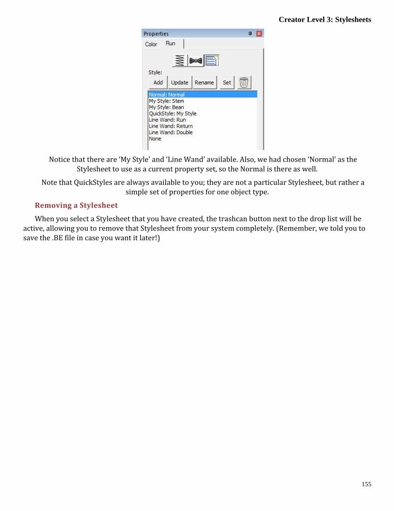
Creator Level 3: Stylesheets
155
Notice that there are ‘My Style’ and ‘Line Wand’ available. Also, we had chosen ‘Normal’ as the Stylesheet to use as a current property set, so the Normal is there as well.
Note that QuickStyles are always available to you; they are not a particular Stylesheet, but rather a simple set of properties for one object type.
Removing a Stylesheet
When you select a Stylesheet that you have created, the trashcan button next to the drop list will be active, allowing you to remove that Stylesheet from your system completely. (Remember, we told you to save the .BE file in case you want it later!)

Designer’s Gallery Platform
156
Path Operations
Path operations are advanced graphical tools that help you quickly get a result shape based on cur-rently selected ones.
USING BREAKLINES
Sometimes you would like to be able to take a pair of scissors to a shape – make a wavy or straight cut across it. You can do this with Breaklines. Using the ‘Break line’ button, having already selected a closed-outline Line object, you enter the Break Mode. Next, select an input mode to draw
your line across the shape, and right-click to end drawing. You can edit the line before it is used. Once you have the line as you would like, use the “Cut the object” button to make the cut. You will now have multi-ple objects.
Start with a circle and draw a Breakline.
Cut the object with the Breakline. You can see it is now two objects.
A Fill stitch has been added and colors chosen.

Creator Level 3: Path Operations
157
CUT
Cut is a path operation that lets you remove a part of a shape, in the form of another shape. Think in terms of a cookie cutter. There is a base shape (earliest in the sequence), your dough in this exam-
ple, and a cookie cutter on top. Position the cutter as you like, select the two shapes, and click the Cut but-ton. The base object will now have its shape adjusted to have the area under the cutter removed.
Here we use a couple shapes from the Library; the Pumpkin and a Flower. Note the Pumpkin is the first object, which is the one that gets operated on. Select both items and click the Cut button which gives the appearance of a ‘bite’ being taken out of the pumpkin. Do we have rabbits in the garden?
AND
This is a more advanced operation where two or more shapes overlap one another, and you want a new shape based on the area where the shapes overlap. The “AND” is where this shape ‘and’ that
shape both exist. It is used more for visual effects – breaking a set of multiple overlapping shapes into even more parts. The results of the AND operation are added after the last object used in the operation.
First, we merged three copies of a circle, then used the AND button.
The result is shown as a red fill on the right.
UNION
When you have two or more shapes that overlap, and you want to make a shape that represents the entire outline of all the shapes, you use the Union button. This could be effective for adding a border
around a design. The new Union shape is added to the design after the last of the shapes involved in the operation.
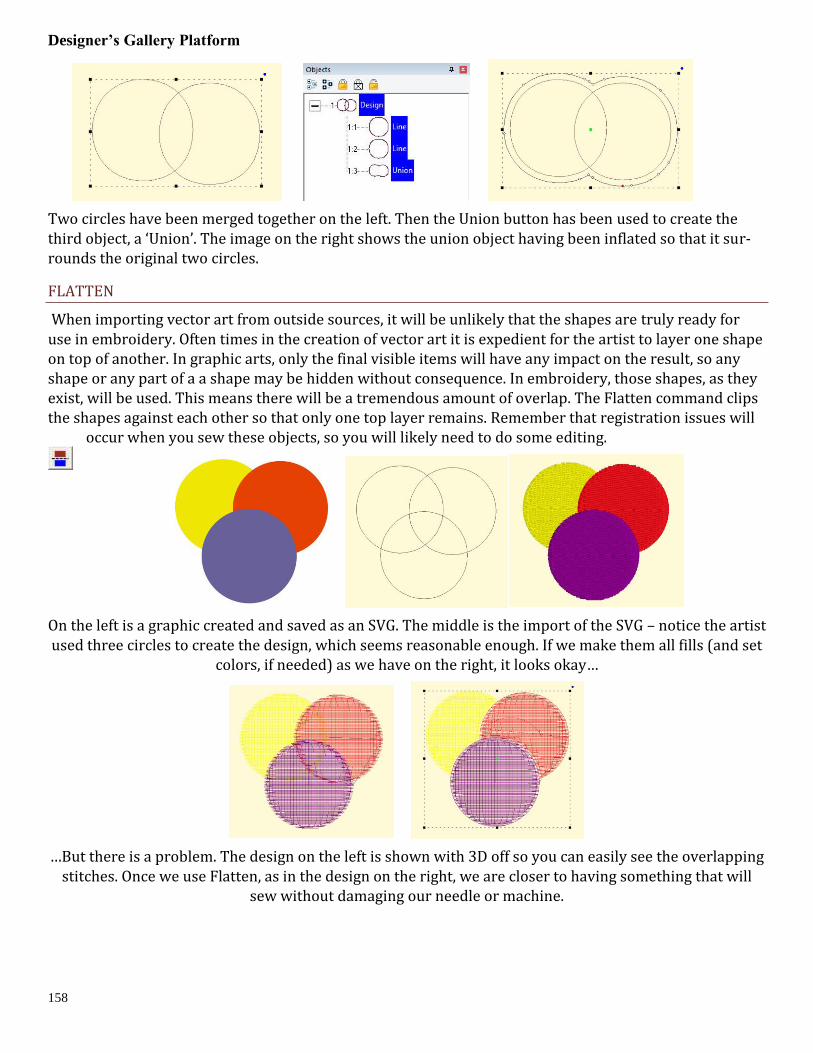
Designer’s Gallery Platform
158
Two circles have been merged together on the left. Then the Union button has been used to create the third object, a ‘Union’. The image on the right shows the union object having been inflated so that it sur-rounds the original two circles.
FLATTEN
When importing vector art from outside sources, it will be unlikely that the shapes are truly ready for use in embroidery. Often times in the creation of vector art it is expedient for the artist to layer one shape on top of another. In graphic arts, only the final visible items will have any impact on the result, so any shape or any part of a a shape may be hidden without consequence. In embroidery, those shapes, as they exist, will be used. This means there will be a tremendous amount of overlap. The Flatten command clips the shapes against each other so that only one top layer remains. Remember that registration issues will
occur when you sew these objects, so you will likely need to do some editing.
On the left is a graphic created and saved as an SVG. The middle is the import of the SVG – notice the artist used three circles to create the design, which seems reasonable enough. If we make them all fills (and set
colors, if needed) as we have on the right, it looks okay…
…But there is a problem. The design on the left is shown with 3D off so you can easily see the overlapping stitches. Once we use Flatten, as in the design on the right, we are closer to having something that will
sew without damaging our needle or machine.

Creator Level 3: Inflating / Deflating shapes
159
Inflating / Deflating shapes
Sometimes you need a shape to increase or decrease in size, but be exactly the same distance around all the lines of the original. This means the new shape will have to change. A classic example
of this is echo quilting, where, as the lines of stitching echo out, the curves become less tight, and fewer details are visible.
Clicking the Inflate button on the Tool Pane displays the Inflate dialog, which allows you to inflate select-ed objects and their holes as needed.
When inflating or deflating, the object selected will change. Thus, if you wish to have the original shape retained on the page (for some other part of the design) you should copy and paste it before inflating. See the next section, ‘Automatic Outlining’ for an example use of inflation.
Automatic Outlining
Automatic outlining will create a shape that surrounds any stitches on the design page. This is use-ful when creating stitches that will add to an existing embroidery design that has been merged onto
the page.
Automatic outlining can also be used to create an object hole. The purpose for this is for quilting designs. You can merge a design or create an interior design with objects, then make a new outline in some larger shape, for instance a quilt block, or your hoop. By adding a hole to that shape, in the form of the current stitches on the page, you can create a stipple, or an echo perhaps, that will surround those stitches and fill the block.
The automatic outlining can be combined with Inflation to allow room around the stitches, for quilting or other purposes. For example, there is a feature elsewhere in the platform which automatically creates knockdown stitches for sewing on terry by first creating an automatic outline, then inflating it slightly, and adding a light fill.
Here’s a quick illustration in use, starting with a basic monogram:
Now we will automatically outline it and set those new objects to a backstitch, made green.
Let’s try a few more steps for fun:

Designer’s Gallery Platform
160
Copy the outlines that were created by the Automatic Outline tool:
So you should see this.
Use the Inflate button to create echoed outlines of the letters. Note the ‘Remove holes’ option is turned on. We are using a 5mm inflation.

Creator Level 3: Automatic Outlining
161
Add a Union. Next, delete the individual ‘Line’ objects, as we won’t need them anymore.
Select the Union and use the menu ‘Create->outline->delete holes.’
Now add a run to the Union, change style, color, etc.

Designer’s Gallery Platform
162
Publishing
When you want to create your own art and use them within other designs, as motifs or embossing pat-terns, you can ‘Publish’ them in several ways, including the creation of a .BX install-file which lets you share your work with others.
CREATING MOTIFS
Motifs are used in Motif Runs and Motif Fills. The motif itself is a design, and can contain any number of Manual, Run and Satin objects, although usually a motif is a singular Manual stitch object. Naturally, a mo-tif cannot contain another motif.
Motifs run left-to-right, by convention in the system. They do get reversed when needed during a fill, but we start with a normal orientation. A motif’s first point and its last point should line up – or rather, they will when used so you might want to consider that as you draw one.
Motifs use the vertical position of the initial and final points as a baseline, like a letter would. The baseline is how much above and below the line the motif will sit.
Manual points are mostly used in motifs, especially since Runs will calculate, and the points where a nee-dle will land are unpredictable when the user is in control of the size. This is doubly true when going around tight curves, where small changes in size will very much affect the position of the stitches.
You can use satins to make a motif, and the satin will generate for the size used in the Motif run or Motif fill. It is generally not needed to use any underlay in the satin, although you can.
Normal motifs are fairly small, typically 2-4mm, so as to be used in a Motif Fill with a reasonable number visible, but they can be large, if warranted. You may want to make a motif that represents a particular cli-ent logo, and embed that in the background of a fill in a larger design.
When storing motifs, you will be saving them on your system for use in the future, but when they are used within an object, they are also stored in that object. This means that if you edit the motif, the object won’t be updated – you’ll need to remove that motif from the object that’s using it, and re-add the new version.
Let’s create a motif by drawing a shape and setting its type to Manual. Note the first and last points are on the baseline.
Now we can publish it (along with any other designs on the page). Click ‘For My Use’:

Creator Level 3: Publishing
163
Now, let’s start a new Motif object. Click Add on the Motif property and select the motif:
The motif, along with the result:

Designer’s Gallery Platform
164
CREATING EMBOSS PATTERNS
Embossing patterns can be either open or closed shapes, but they will be used differently depending which they are. Open shapes are used as repeating carving lines in a normal fill.
Closed shapes will have the fill stitches that lie internal to the shape removed, unless that makes for an extra-long stitch. The effect of closed shapes in a fill is that of satin areas within the fill, and those provide dramatic relief from the fill stitching; almost a trapunto effect.
In order to ‘see’ more of the embossed pattern, keep its size within the realm of your stitch length or smaller – typically 3.0mm - 5.5mm.
Embossing patterns are done with Line objects, as stitches have no effect in the design. Also, you do not have to worry about transits, overlap, and color or anything but the shape that is your desired result.
Emboss patterns are shapes that intersect the existing stitches thus causing a needle-penetration. When the shape is parallel to the stitches, it may not intersect; hence you can have sides of your shape that do not create stitches. This is usually overcome by adjusting the inclination angle a little bit, or rotating the emboss pattern, so that more intersections occur.
Keep in mind what your emboss pattern will look where its pattern will set next to a copy of itself; the design’s right edge shape will interact with its left edge.
When storing emboss patterns, you will be saving them on your system for use in the future, but when they are used within an object, they are also stored in that object. This means that if you edit the pattern, the object won’t be updated – you’ll need to remove that pattern from the object that’s using it, and re-add the new version.
Let’s go through the process. Here we have drawn some line art in two designs.
Next, we have a shape with a fill, and we’ll add an embossing:

Creator Level 3: Exporting Vector Art
165
Notice the angle of inclination to cause more intersections in the result:
Exporting Vector Art
Artwork drawn in the program can be exported as a vector file in .svg format and for popular cutting ma-chines. Use the menu ‘File->Export’ to save the artwork. This is not the same as the applique functions to save cut-files (located on the Applique tab of the Color Window). Those outlines are processed to directly cut an applique. The files saved when Exporting are the objects as-drawn.

Designer’s Gallery Platform
166
CORRECTING SEWING ISSUES
An Embroidery machine is not a ‘thread printer’. Often times we hear that a design looked perfect on the screen, but didn’t sew out that way. It almost never will sew out the way you see it onscreen. As the design sews, thread is being pushed through the fabric, opening it up, tightening it in the hoop, reducing its elasticity and drawing it together. As the fabric moves, the ‘location’ of all subsequent stitches is going to be incorrect by some small amount. This produces various sewing defects such as loss of registration, puckering/gathering, dancing baselines, poor coverage and even fabric tearing. If we pay attention to how we construct the design we can minimize these difficulties, and even use them to our advantage if we are crafty. We also want to allow our objects the ability to move around a bit, and anchor them as needed. It is a process guided by experience. Let’s look at some common issues:
REGISTRATION
Registration describes the effect in areas where two or more objects meet at their edges. If the objects stitch tightly up against each other so that there is no background color bleeding through, the registration is considered ‘tight’ or correct. As a design is being created, it is worthwhile to think about registration – you can add overlap to your shapes or add compensation which could save you time later when you edit the design.
Switching fabric, project types or even machines and hoops will affect the registration of any design. This is why you often hear that digitizing for hats should be done by a professional – the registration is-sues compound. The verb ‘compound’ here means that each object that sews will affect the location that the next object will sew. This happens because the fabric gets distorted a little bit for each and every stitch. What you see on the computer screen does not include the distortion that occurs during stitching.
How do you fix it?
You will have to do the same thing that people before you have done; sew, edit, sew, edit, sew until you see the result you need, then try to remember what you did the next time you create a design. It’s a process that gets much easier once you have some real experience, and the only way for that to happen is for you to do it.
Registration issues come in a couple common forms when digitizing.
1.) Outline stitches are separated from filled areas.
There are some tricks to making outlines register. The easiest is not to use them. This is a de-sign style issue, and we see through the years that designs will sometimes come with a double-stitch or bean-stitch outline around everything. There is no rule that says you need to do this. Only use outlines where it is important to make the artwork appear crisper.
Another way to help outline stitches is to give them more body; a bean stitch will work better than a single or double run. A backstitch or stemstitch is wider and therefore naturally going to ‘hide’ any registration issues easier.
When creating the outline, place your points slightly inset into the stitches that they surround – per-haps only half a needle-width 3-4 stitch points for your first try. All fills and satins tend to ‘draw’ the fab-ric in because of tension, and the thread has to curve down toward the fabric where the needle pene-trates. This causes the outline stitch to be pushed away. Therefore in-setting the outline, if only slightly, will help the result.

Correcting Sewing issues
167
In the above image, notice that the inset of the darker-colored run is greater at the sides, and almost perfectly aligned at the top and bottom. This is because the fill will sew ‘narrower’ along the inclination – each line of stitching wants to pull the fabric in.
At the top or bottom, whichever stitches later, you may see the fill (or more typically a satin) ‘push’ or get ‘taller’ before the run happens.
Adjacent filled areas pull away at the ends of the stitch lines.
When a line of stitching ends, be it from a fill or a satin, there is tension which pulls the fabric in the opposite direction of the line. This means that a fill or satin tends to sew ‘narrower’ than the object was drawn. We do use the compensation setting to help this – it makes the ends of the stitching a little bit far-ther out past the edge of the shape. It helps, but sometimes that’s not enough, especially where two fills or satin edges meet.
Solving this usually is done by overlapping the object shapes. The shapes can overlap quite a bit some-times if there is compound registration from more than two objects all positioned at each others’ edges.
If there is an edge-run in each object, for underlay or travel purposes, sometimes you can use it as an ‘anchor’ for a subsequent object; move the outline so that it overlaps just to that edge-run and has some needle penetrations which grab it. This tends to balance the stress on the fabric between both adjacent objects.
In the image above, you can see the earlier yellow object has its outline inset ‘under’ the red and pur-ple objects, which allows for a degree of freedom of movement while it is being sewn. The other objects will not overlap as much as it appears on screen.

Designer’s Gallery Platform
168
Oh, look, a rainbow, how nice! No. No, it isn’t. This is a perfect example of compound registration at work and you will not be able to sew this consistently.
The red, then yellow, then green sew in that order. It sounds right. But the gaps you see when you sew will make you wonder if you should take the machine in for repair. This will probably work better going outside-in with the green, then the red, then the yellow, and don’t be surprised to have the green and red objects nearly touch each other in the middle under the yellow.
Do not do it like this:
Rather, more like this:

Correcting Sewing issues
169
COVERAGE
Watching a child use a crayon to color an image will help you understand this quite clearly. If you move the crayon back and forth in one direction, the edges of what you are coloring will not have as much color as the center. Typically an older child will work the crayon along the edges at some point which will extend the color more evenly. The same is true for embroidery. Using multiple layers of stitching, with different directions, yields better coverage. It also divides up the shift in the fabric, which helps registra-tion; instead of everything being pushed one way, it gets pushed half as much in two directions, and your stabilizer will be better able to support it.
This means that if you want more coverage, try making two passes or more, each with less density (instead of one pass at 4pt, try two at 8pt). This is in fact the reason for the underlay options in fills and satins.
FILL COVERAGE
When doing a fill, often times you will want to position your Exit bead somewhere in the ‘middle’ of the shape. This means that the pattern will sew one part of the design, then go away and work its way back. If your fabric is being flattened by the thread, and you do not have undersewing for better coverage, this can leave what appears to be an ‘unstitched’ line across your fill. There are solutions for this – use more in the way of underlay, and/or move the exit bead to the opposite ‘end’ of the pattern. It is often better to ‘run’ to the next object after your fill than to have the fill exit in the middle.
Left: A fill with the Exit bead midway in the fill. This causes the stitching to go from one side, then the other as shown in the center image, which is shown using the sewing simulator (in this image it has sewn below, and is now working its way down from the top).
Right: Entry and Exit Beads are at opposite ends, which can help the fill provide a smoother coverage.

Designer’s Gallery Platform
170
“MACHINE ISSUES”
We see these often enough that they are worth mentioning here.
THREAD LOOPS ON THE BOTTOM OF THE FABRIC
This is always caused by the TOP thread having no tension, or not being in the take-up lever. It sounds counter-intuitive, but it’s true, the bottom of the design is controlled by the top thread, not the bobbin.
THREAD COMING UP
Usually this is a bobbin case tension too loose, or not having the bobbin thread in the tension at all. While it is possible that the top thread is getting hung up coming from the spool (very common actually) this usually happens in specific areas and appears quite severe. If you are seeing a lot of points coming up, it is usually the bobbin not having tension.
MACHINE GUN SOUND
It sounds silly, but yes, that rat-at-tap-tap can be annoying and even destructive to the machine. Usu-ally this is your hoop flopping around when the needle rises out of the fabric. The needle lifts it up just a bit, then pops out, and the hoop flops down. It could mean the hoop is mounted wrong, is defective or simply a bad design. You can help by making sure you have a sharp needle, sized as small as you can for your thread. And you can try putting something on the arm of the machine to soften the blow. And defi-nitely have it checked by a competent sewing machine service.

Correcting Sewing issues
171
HELP
Getting help for Designer’s Gallery products is just a few clicks away!
www.designersgallerysoftware.com