the development of a prototype of bionic eyes for visual
TRANSCRIPT

Proceedings of the 4th IIAE International Conference on Intelligent Systems and Image Processing 2016
© 2016 The Institute of Industrial Applications Engineers, Japan.
The Development of a Prototype of Bionic Eyes for Visual Impairment
Ponglert Rattanachinalaia*, Wanglok Dob, Soranut Kittipanyangamc, Kei Eguchid a,b,c,dFukuoka Institute of Technology, 3-30-1 Wajiro Higashi,
Higashi Ward, Fukuoka, 811-0295, Japan
Corresponding Author: [email protected], [email protected], [email protected], [email protected]
Abstract
Nowadays, people who have visual impairment like
blindness which make them completely lost there’s vision,
they may have a lot of things to help them in daily life.
Example; Braille, White cane, Foot path sign and others.
However, there is some reason those item is not enough for
them. Many researchers develop Visual Prosthesis that can
restore the lost vision of blind people, but those device are
too large. Some of it is not portable. And uses complex
components.
In this paper, we design and develop the prototype of
Visual Prosthesis named Bionic Eyes. Bionic Eyes consists
of two parts Smart Glasses and Artificial Eye. The first part
of system is Smart Glasses that can be built from a tiny
computer or microprocessor. The second part is Artificial
Eye that can be built from small circuit that has the same size
as eye ball. We can proceed through a lot of process like
image processing easily by using Intel Edison as our main
processor unit for Smart Glasses.
Keywords: Visual Prosthesis, Visual Impairment, Edge
Detection, Image Processing.
1. Introduction
Blind people have a lot of inconvenient in their life (1).
Walking, eating, working, or something like these, there are
normal people can doing it easily, but blind people cannot do
it as us. When people become blind or blind from birth, they
gained other superior sensing ability of listening or touching
things in return. They can hear a sound better than normal
people. However they have those superior sensing abilities,
it’s still not enough for them. The ability in vision is
incomparable. In order to restore blind people’s lost vision,
researcher had developed Visual prosthesis.
Previous Visual prosthesis that have been developed by
others researcher was used many complex components that
make the size of visual prosthesis too large. It may cost a lot
of money to build just 1 device for blind people. When the
size of Visual prosthesis is too large, it could become
inconvenient to use in everyday life of blind people. Image
that blind people can see from using those Visual prosthesis
may not be perfectly clear, because methods of reducing
image’s information to easily transmit were still not good
enough, and some of the method to restore the lost vision of
patients looks dangerous for human’s brain.
To solve the problem about previous Visual prosthesis,
we designed and developed a prototype Visual Prosthesis
named Bionic Eyes. Bionic Eyes consists of two parts: Smart
Glasses and Artificial Eye. We divided Bionic Eyes into two
parts of system because the area for eyeball on human’s body
have limitation. Smart Glasses will use image processing on
main processor unit to extract necessary information from
image, resize image and convert image into binary text file
to transmit to the Artificial Eye. Image processing algorithm
that we used is Edge Detection method. This method will
extract necessary information of image into black and white
image. This black and white image have a good information
on it that we can easily understand what is in the image better
than the previous Visual Prosthesis.
Smart Glasses could easily build with one tiny
computer called Intel Edison. Intel Edison is our main
processor unit for Smart Glasses. Intel Edison have a
necessary function like embedded Wi-Fi and Bluetooth,
Fig. 1. The “dot of light” cause by Phosphene phenomenon
that human’s eye can see
DOI: 10.12792/icisip2016.049 272
embedded memory and RAM. Intel Edison which is as small
as a stamp. It mean that our Visual Prosthesis system size
will not become too large like the others. Inside of Artificial
Eyes that will be a replacement for human’s eye ball, have a
necessary small circuit for communicating with Smart
Glasses, creating current neural signal and transmission to
human’s optic nerve. With these method it will not be
harmful to human’s brain like others method too.
2. Research Survey
In the present, methods of using Visual Prosthesis to
restore lost vision of patient have 3 main methods.
(a) Stimulus of Visual Cortex
This method is an idea that uses the device sending
signal wave to visual cortex of human’s brain cerebral cortex
that is responsible for processing visual information, or using
microelectrode arrays (MEAs) direct penetrating to human’s
visual cortex and generating a “dot of light” called
Phosphene Phenomenon by stimulus the brain’s visual cortex (2). As shown in Fig. 1, it is the Phosphene Phenomenon.
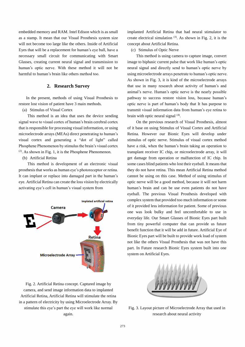
(b) Artificial Retina
This method is development of an electronic visual
prosthesis that works as human eye’s photoreceptor or retina.
It can implant or replace into damaged part in the human’s
eye. Artificial Retina can create the loss vision by electrically
activating eye’s cell in human’s visual system from
Fig. 2. Artificial Retina concept. Captured image by
camera, and send image information data to implanted
Artificial Retina, Artificial Retina will stimulate the retina
in a pattern of electricity by using Microelectrode Array. By
stimulate this eye’s part the eye will work like normal
again.
implanted Artificial Retina that had neural stimulator to
create electrical simulation (3). As shown in Fig. 2, it is the
concept about Artificial Retina.
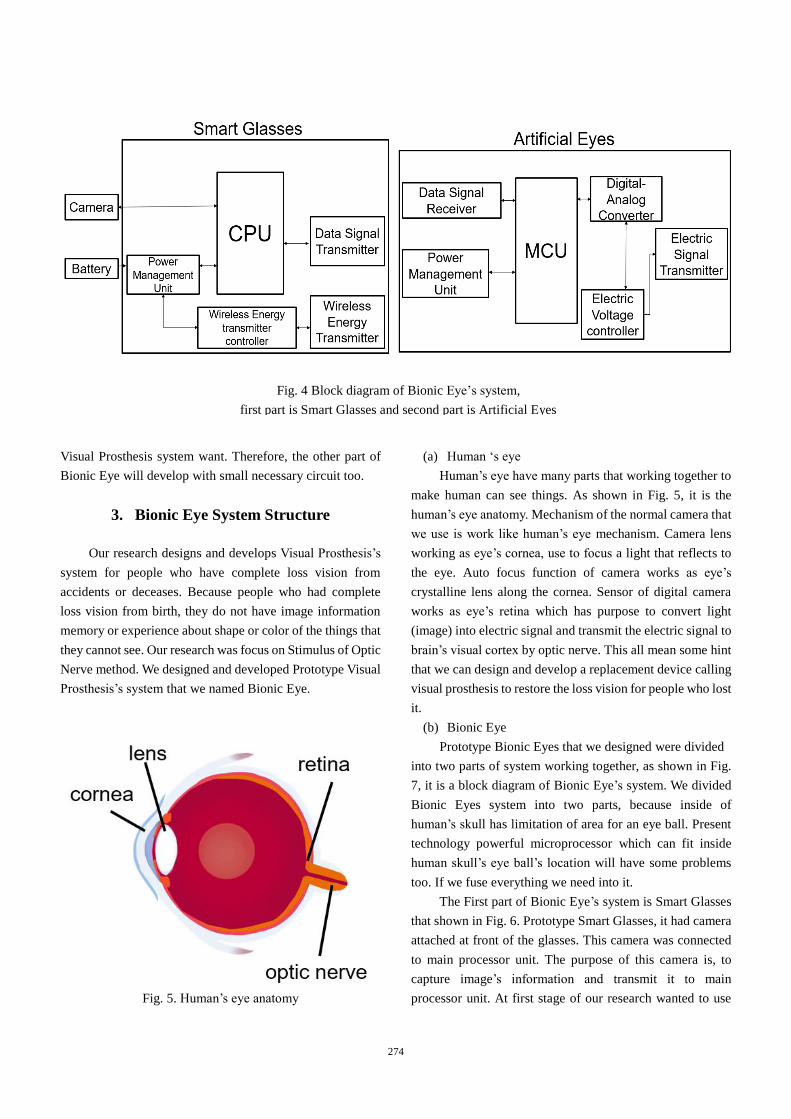
(c) Stimulus of Optic Nerve
This method is using camera to capture image, convert
image to biphasic current pulse that work like human’s optic
neural signal and directly send to human’s optic nerve by
using microelectrode arrays penetrate to human’s optic nerve.
As shown in Fig. 3, it is kind of the microelectrode arrays
that use in many research about activity of human’s and
animal’s nerve. Human’s optic nerve is the nearly possible
pathway to success restore vision loss, because human’s
optic nerve is part of human’s body that It has purpose to
transmit visual information data from human’s eye retina to
brain with optic neural signal (4).
On the previous research of Visual Prosthesis, almost
of it base on using Stimulus of Visual Cortex and Artificial
Retina. However our Bionic Eyes will develop under
stimulus of optic nerve. Stimulus of visual cortex method
have a risk, when the human’s brain taking an operation to
transplant receiver IC chip, or microelectrode array, it will
get damage from operation or malfunction of IC chip. In
some cases blind patients who lost their eyeball. It means that
they do not have retina. This mean Artificial Retina method
cannot be using on this case. Method of using stimulus of
optic nerve will be a good method, because it will not harm
human’s brain and can be use even patients do not have
eyeball. The previous Visual Prosthesis developed with
complex system that provided too much information or some
of it provided less information for patient. Some of previous
one was look bulky and feel uncomfortable to use in
everyday life. Our Smart Glasses of Bionic Eyes part built
from tiny powerful computer that can provide us future
benefit function that it will be add in future. Artificial Eye of
Bionic Eyes part will be built to provide work load of system
not like the others Visual Prosthesis that was not have this
part. In Future research Bionic Eyes system built into one
system on Artificial Eyes.
Fig. 3. Layout picture of Microelectrode Array that used in
research about neural activity
273
Visual Prosthesis system want. Therefore, the other part of
Bionic Eye will develop with small necessary circuit too.
3. Bionic Eye System Structure
Our research designs and develops Visual Prosthesis’s
system for people who have complete loss vision from
accidents or deceases. Because people who had complete
loss vision from birth, they do not have image information
memory or experience about shape or color of the things that
they cannot see. Our research was focus on Stimulus of Optic
Nerve method. We designed and developed Prototype Visual
Prosthesis’s system that we named Bionic Eye.
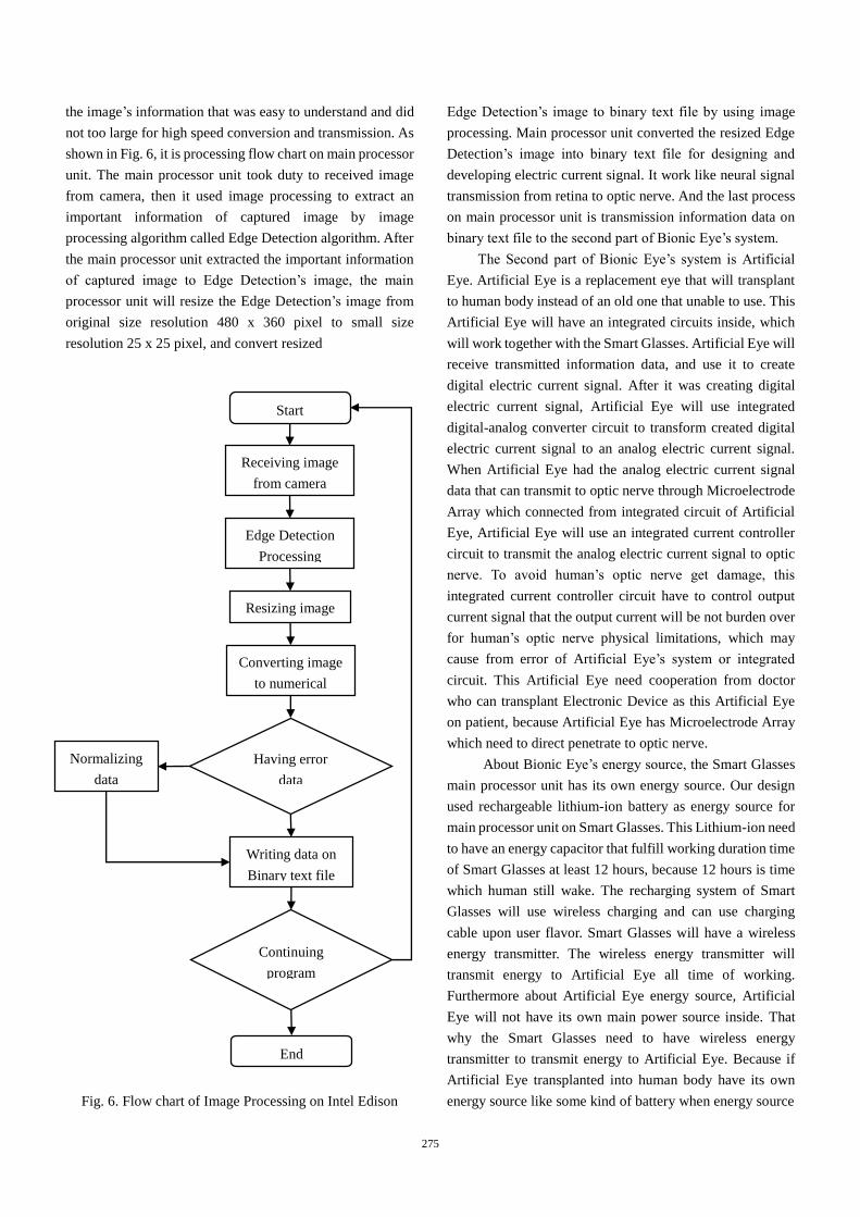
Fig. 5. Human’s eye anatomy
(a) Human ‘s eye
Human’s eye have many parts that working together to
make human can see things. As shown in Fig. 5, it is the
human’s eye anatomy. Mechanism of the normal camera that
we use is work like human’s eye mechanism. Camera lens
working as eye’s cornea, use to focus a light that reflects to
the eye. Auto focus function of camera works as eye’s
crystalline lens along the cornea. Sensor of digital camera
works as eye’s retina which has purpose to convert light
(image) into electric signal and transmit the electric signal to
brain’s visual cortex by optic nerve. This all mean some hint
that we can design and develop a replacement device calling
visual prosthesis to restore the loss vision for people who lost
it.
(b) Bionic Eye
Prototype Bionic Eyes that we designed were divided
into two parts of system working together, as shown in Fig.
7, it is a block diagram of Bionic Eye’s system. We divided
Bionic Eyes system into two parts, because inside of
human’s skull has limitation of area for an eye ball. Present
technology powerful microprocessor which can fit inside
human skull’s eye ball’s location will have some problems
too. If we fuse everything we need into it.
The First part of Bionic Eye’s system is Smart Glasses
that shown in Fig. 6. Prototype Smart Glasses, it had camera
attached at front of the glasses. This camera was connected
to main processor unit. The purpose of this camera is, to
capture image’s information and transmit it to main
processor unit. At first stage of our research wanted to use
Fig. 4 Block diagram of Bionic Eye’s system,
first part is Smart Glasses and second part is Artificial Eyes
274
the image’s information that was easy to understand and did
not too large for high speed conversion and transmission. As
shown in Fig. 6, it is processing flow chart on main processor
unit. The main processor unit took duty to received image
from camera, then it used image processing to extract an
important information of captured image by image
processing algorithm called Edge Detection algorithm. After
the main processor unit extracted the important information
of captured image to Edge Detection’s image, the main
processor unit will resize the Edge Detection’s image from
original size resolution 480 x 360 pixel to small size
resolution 25 x 25 pixel, and convert resized
Fig. 6. Flow chart of Image Processing on Intel Edison
Edge Detection’s image to binary text file by using image
processing. Main processor unit converted the resized Edge
Detection’s image into binary text file for designing and
developing electric current signal. It work like neural signal
transmission from retina to optic nerve. And the last process
on main processor unit is transmission information data on
binary text file to the second part of Bionic Eye’s system.
The Second part of Bionic Eye’s system is Artificial
Eye. Artificial Eye is a replacement eye that will transplant
to human body instead of an old one that unable to use. This
Artificial Eye will have an integrated circuits inside, which
will work together with the Smart Glasses. Artificial Eye will
receive transmitted information data, and use it to create
digital electric current signal. After it was creating digital
electric current signal, Artificial Eye will use integrated
digital-analog converter circuit to transform created digital
electric current signal to an analog electric current signal.
When Artificial Eye had the analog electric current signal
data that can transmit to optic nerve through Microelectrode
Array which connected from integrated circuit of Artificial
Eye, Artificial Eye will use an integrated current controller
circuit to transmit the analog electric current signal to optic
nerve. To avoid human’s optic nerve get damage, this
integrated current controller circuit have to control output
current signal that the output current will be not burden over
for human’s optic nerve physical limitations, which may
cause from error of Artificial Eye’s system or integrated
circuit. This Artificial Eye need cooperation from doctor
who can transplant Electronic Device as this Artificial Eye
on patient, because Artificial Eye has Microelectrode Array
which need to direct penetrate to optic nerve.
About Bionic Eye’s energy source, the Smart Glasses
main processor unit has its own energy source. Our design
used rechargeable lithium-ion battery as energy source for
main processor unit on Smart Glasses. This Lithium-ion need
to have an energy capacitor that fulfill working duration time
of Smart Glasses at least 12 hours, because 12 hours is time
which human still wake. The recharging system of Smart
Glasses will use wireless charging and can use charging
cable upon user flavor. Smart Glasses will have a wireless
energy transmitter. The wireless energy transmitter will
transmit energy to Artificial Eye all time of working.
Furthermore about Artificial Eye energy source, Artificial
Eye will not have its own main power source inside. That
why the Smart Glasses need to have wireless energy
transmitter to transmit energy to Artificial Eye. Because if
Artificial Eye transplanted into human body have its own
energy source like some kind of battery when energy source
Start
Resizing image
Having error
data
Continuing
program
End
Writing data on
Binary text file
Normalizing
data
Converting image
to numerical
Edge Detection
Processing
Receiving image
from camera
275
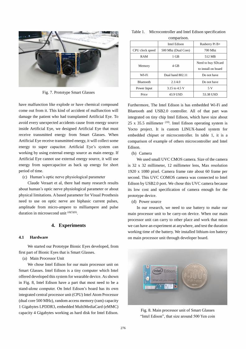
Fig. 7. Prototype Smart Glasses
have malfunction like explode or have chemical compound
come out from it. This kind of accident of malfunction will
damage the patient who had transplanted Artificial Eye. To
avoid every unexpected accidents cause from energy source
inside Artificial Eye, we designed Artificial Eye that must
receive transmitted energy from Smart Glasses. When
Artificial Eye receive transmitted energy, it will collect some
energy to super capacitor. Artificial Eye’s system can
working by using external energy source as main energy. If
Artificial Eye cannot use external energy source, it will use
energy from supercapacitor as back up energy for short
period of time.
(c) Human’s optic nerve physiological parameter
Claude Veraart et al, there had many research results
about human’s optic nerve physiological parameter or about
physical limitations. A based parameter for Visual Prosthesis
need to use on optic nerve are biphasic current pulses,
amplitude from micro-ampere to milliampere and pulse
duration in microsecond unit (4)(5)(6).
4. Experiments
4.1 Hardware
We started our Prototype Bionic Eyes developed, from
first part of Bionic Eyes that is Smart Glasses.
(a) Main Processor Unit
We chose Intel Edison for our main processor unit on
Smart Glasses. Intel Edison is a tiny computer which Intel
offered developed this system for wearable device. As shown
in Fig. 8, Intel Edison have a part that most need to be a
stand-alone computer. On Intel Edison’s board has its own
integrated central processor unit (CPU) Intel Atom Processor
(dual core 500 MHz), random access memory (ram) capacity
1 Gigabytes LPDDR3, embedded MultiMediaCard (eMMC)
capacity 4 Gigabytes working as hard disk for Intel Edison.
Furthermore, The Intel Edison is has embedded Wi-Fi and
Bluetooth and USB2.0 controller. All of that part was
integrated on tiny chip Intel Edison, which have size about
25 x 35.5 millimeter (10). Intel Edison operating system is
Yocto project. It is custom LINUX-based system for
embedded chipset or microcontroller. In table 1, it is a
comparison of example of others microcontroller and Intel
Edison.
(b) Camera
We used small UVC CMOS camera. Size of the camera
is 32 x 32 millimeter, 12 millimeter lens, Max resolution
1920 x 1080 pixel. Camera frame rate about 60 frame per
second. This UVC COMOS camera was connected to Intel
Edison by USB2.0 port. We chose this UVC camera because
its low cost and specification of camera enough for the
prototype device.
(d) Power source
In our research, we need to use battery to make our
main processor unit to be carry-on device. When our main
processor unit can carry to other place and work that mean
we can have an experiment at anywhere, and test the duration
working time of the battery. We installed lithium-ion battery
on main processor unit through developer board.
Fig. 8. Main processor unit of Smart Glasses
“Intel Edison”, that size around 500 Yen coin
Table 1. Microcontroller and Intel Edison specification
comparison.
Intel Edison Rasberry Pi B+
CPU clock speed 500 Mhz (Dual Core) 700 Mhz
RAM 1 GB 512 MB
Memory 4 GB Need to buy SDcard
to install on board
WI-Fi Dual band 802.11 Do not have
Bluetooth 2.1/4.0 Do not have
Power Input 3.15 to 4.5 V 5 V
Price 43.9 USD 53.38 USD
276
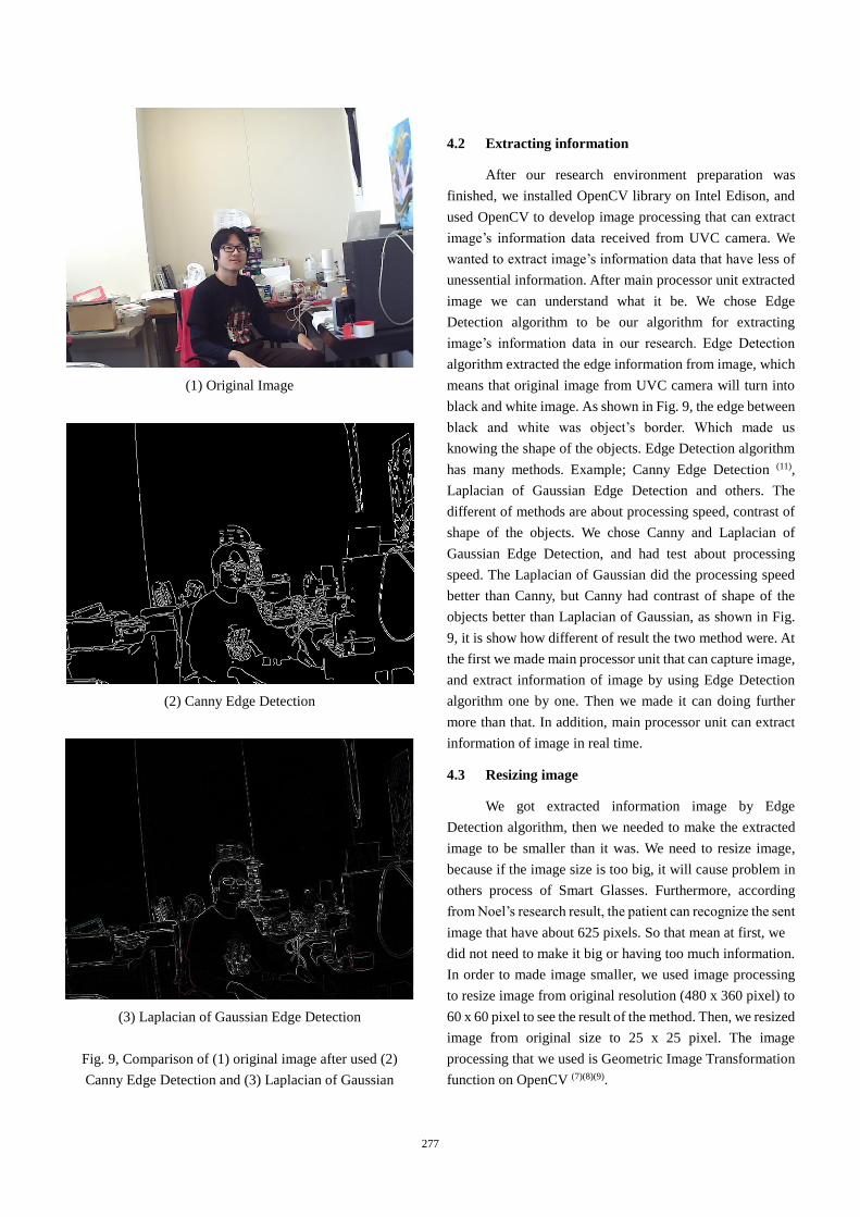
(1) Original Image
(2) Canny Edge Detection
(3) Laplacian of Gaussian Edge Detection
Fig. 9, Comparison of (1) original image after used (2)
Canny Edge Detection and (3) Laplacian of Gaussian
4.2 Extracting information
After our research environment preparation was
finished, we installed OpenCV library on Intel Edison, and
used OpenCV to develop image processing that can extract
image’s information data received from UVC camera. We
wanted to extract image’s information data that have less of
unessential information. After main processor unit extracted
image we can understand what it be. We chose Edge
Detection algorithm to be our algorithm for extracting
image’s information data in our research. Edge Detection
algorithm extracted the edge information from image, which
means that original image from UVC camera will turn into
black and white image. As shown in Fig. 9, the edge between
black and white was object’s border. Which made us
knowing the shape of the objects. Edge Detection algorithm
has many methods. Example; Canny Edge Detection (11),
Laplacian of Gaussian Edge Detection and others. The
different of methods are about processing speed, contrast of
shape of the objects. We chose Canny and Laplacian of
Gaussian Edge Detection, and had test about processing
speed. The Laplacian of Gaussian did the processing speed
better than Canny, but Canny had contrast of shape of the
objects better than Laplacian of Gaussian, as shown in Fig.
9, it is show how different of result the two method were. At
the first we made main processor unit that can capture image,
and extract information of image by using Edge Detection
algorithm one by one. Then we made it can doing further
more than that. In addition, main processor unit can extract
information of image in real time.
4.3 Resizing image
We got extracted information image by Edge
Detection algorithm, then we needed to make the extracted
image to be smaller than it was. We need to resize image,
because if the image size is too big, it will cause problem in
others process of Smart Glasses. Furthermore, according
from Noel’s research result, the patient can recognize the sent
image that have about 625 pixels. So that mean at first, we
did not need to make it big or having too much information.
In order to made image smaller, we used image processing
to resize image from original resolution (480 x 360 pixel) to
60 x 60 pixel to see the result of the method. Then, we resized
image from original size to 25 x 25 pixel. The image
processing that we used is Geometric Image Transformation
function on OpenCV (7)(8)(9).
277

25 x 25 Pixel (True Scale)
Fig. 10, the result of resized image from original resolution
to 60 x 60 pixel and then 25 x 25 pixel. At the bottom of
figure is resized image true scale resolution 25 x 25 pixel
that human eye can see in computer
Geometric Image Transformation function will not change
image information or content, but it will deform pixel grid
and map to destination grid image. For each pixel (x, y) of
destination image, the Geometric Image Transformations
function will calculate coordinates of corresponding donor
pixel from image source and then it will copy the pixel value
as show on equation.
𝑑𝑠𝑡(𝑥, 𝑦) = 𝑠𝑟𝑐(𝑓𝑥(𝑥, 𝑦), 𝑓𝑦(𝑥, 𝑦)) (1)
As show on Fig. 10, is the result of resized image from
original resolution (480 x 360 pixel) to 25 x 25 pixel.
Fig. 11, Extracted pixel value of resized Laplacian of
Gaussian Edge Detection image. Red line number 1
(0, 0, 0) mean black color pixel, number 2 (255, 255, 255)
mean white color pixel and number 3 (160, 152, 100) and
other values mean others color pixel (error)
4.4 Converting image
In this part, we got resized image from resizing image
method. After that we need to convert resized image into
binary text file to get each line of pixel value. Digital image
is numeric representation of a two dimension image. The
digital image may be raster or vector image that fixed by
resolution of image. Raster image or bitmapped image, in
image contain the value of pixel. Sorted in each line and
column that make us seeing picture or shape. Main processor
unit used image processing to read the each line and column
of resized image, extracted pixel value of each line and column and wrote pixel value to binary text file. As shown
in Fig. 11, in case of using Laplacian of Gaussian method in
Edge Detection algorithm, main processor unit should get
Red Blue Green (RGB) value like (0, 0, 0) that means black
color pixel and (255, 255, 255) that means white color pixel.
However we got others pixel value from resized image that
used Laplacian of Gaussian Edge Detection as shown in Fig.
11. Because Laplacian of Gaussian method did not write out
black and white color absolutely, it had error processing
when extracted and represented image’s objects. We added
function into main processor unit to normalized each value
pixel into one digit value, (0, 0, 0) to 0, (255, 255, 255) to 1.
Furthermore, we fixed others pixel value that were not black
or white by normalized it to white color pixel 1. Because the
error pixel value is the white color pixel, they were not black
color pixel. We normalized extracted pixel value of image
because the data content on binary text file can be transmit
to Artificial Eye with no complexity. After main processor
unit got binary text file that data content of it was normalized,
it will send this data content to Artificial Eye. Artificial Eye
can use that data content to create electric current signal
designed that will design by us.
5. Conclusions
Our research is designing and developing preprocess of
Visual Prosthesis named Bionic Eyes. Bionic Eyes consists
of two parts: Smart Glasses and Artificial Eye. In the present
prototype Smart Glasses can receive image from camera and
extract necessary information using image processing
algorithm, resizing image and converting image in real time.
It could be carried to use everywhere because we had
mounted lithium-ion battery on it.
Our Future tasks are designing and developing
Artificial Eye’s circuit and energy transmitter part of Smart
Glasses and receiver part of Artificial Eye.
278

Acknowledgment
The authors thank Prof.Dr. Kei Eguchi of Fukuoka
Institute of Technology for providing Bionic Eye’s research
material.
References
(1) Lei Zhao, Kaijie Wu, Xinyu Chai, Chaochen Gu, et al:
“Image Processor for Visual Prosthesis Based on ARM”,
Biomedical Engineering and Informatics, PP.592-596,
2014
(2) N.R. Srivastava, P.R. Troyk, G.Dagnelie, D.Bradley :
“Test Setup for Supporting Human Implantation of
Intracortical Visual Prosthesis Device”, 3rd International
IEEE EMBS Conference on Neural Engineering,
PP.442-445, 2007
(3) James D. Weiland, Mark S. Humayun : “Visual
Prosthesis”, Proceeding of the IEEE, Vol. 96, No.7,
PP.1076-1084, 2008
(4) Mingjie Sun, Kaijie Wu, Pengjia Cao, Xinyu Chai,
Qiushi Ren : “Discrepancy of Electrical Evoked
Potentials by Different Spatial-Temporal Stimulations
of Optic Nerve Using Penetrating Electrode Array”,
IEEE/ICME International Conference on Complex
Medical Engineering, PP.1293-1297, 2007
(5) Ying Zhao, Jia Wang, Xinyu Chai, Qiushi Ren : “Micro-
stimulator Design for Visual Prosthesis based on Optic
Nerve Stimulation”, 2006 International Symposium on
Biophotonics, Nanophotonics and Metamaterials, PP.1-
4, 2006
(6) Jiajia Wang, Pengjia Cao, Liming Li : “A Preliminary
Simulation Study of Virtual Channel Generated by
Penetrating Optic Nerve Electrical Stimulation”,
BioMedical Engineering and Informatics, PP.522-526,
2014
(7) Borgefors, Gunilla : “Distance transformations in digital
image”, Comput. Vision Graph. Image Process.34 3, PP.
344-371, 1986
(8) Felzenszwalb, Pedro F. and Huttenlocher, Daniel P. :
“Distance Transforms of Sampled Functions”, 2004
(9) OpenCV Team : “OpenCV Reference Manual”, 2014
(10) Intel : “Intel Edison Module Hardware Guide”, PP.7-28,
2014
(11) John Canny : “A Computational Approach to Edge
Detection”, IEEE Transactions on Pattern Analysis and
Machine Intelligence, Vol. PAMI-8, No.6, PP.680-698,
1986
279