the egrid and wtdtf electrical grid monitoring system · the egrid and wtdtf electrical grid...
TRANSCRIPT

The eGRID and WTDTF Electrical Grid Monitoring System
John McIntosh Fellow Engineer [email protected]
2nd Annual International Workshop on Grid Simulator Testing of Energy Systems and Wind Turbine Powertrains September 17-18, 2014
SRNL-L4500-2014-00078

Wind Turbine Drivetrain Testing Facility (WTDTF) Data Acquisition System
Components • Temperature Monitoring System • High Speed Data Acquisition • Electrical Grid Monitoring • Low Speed Voltages, Current, Facility Monitoring System • Real Time Vibration Monitoring System
General Requirements • Synchronization of data • High (>2000 S/sec) and low speed (1 S/sec) data • EMI/RFI noise immunity • Secure yet accessible data
2

Clemson eGRID Control and Data Acquisition System
• Low speed grid monitoring data acquisition supplemental to real time systems • Control of switchgear via a HMI integral to facility testing setup and execution
3

Facility Electrical Design
Early Single Line
Near Final Design • Number of switchgear components increased significantly with the addition of the eGRID facility • Final design includes: 29 Feeder Protection Relays, 5 Transformer Protection Relays, 3 High
Impedance Differential Relays, 7 Advanced Reclosers, 9 Overcurrent Protection Systems
4

Electrical Grid Monitoring and Control Design
Requirements • Full control of facility relays via remote HMI using Ethernet communication • Continuous electrical data available e.g. Volts/Amps/Frequency/ Status-Open/Closed/Fault • Ability to obtain high speed data from a relay for analysis • Although relays are “shared” in the facility, independent information needed to be available to
the three control rooms: Large Test Rig, Small Test Rig, eGRID
Vendor Selected Schweitzer Engineering Laboratories (SEL) in Charlotte
Collaboration • Clemson University – facility electrical design • Savannah River National Laboratory – data acquisition requirements and system design • National Instruments – data transfer coding design • Schweitzer Engineering Laboratories – SEL hardware design and HMI design/implementation
5

Grid Monitoring Topology and Communication Design
DNP3 vs. Modbus • SEL hardware includes a “Real Time Automation Controller” (RTAC) which handles all
communication with SEL equipment
• Two ways the RTAC can transfer data to external systems is via a DNP3 (Distributed Network Protocol) or Modbus protocol.
• DNP3 is a Utility industry data protocol that requires a server to direct data to a custom data acquisition system
• Modbus is a common serial communication protocol that can stream data to a custom data acquisition system
• Although DNP3 data communication is more complicated than Modbus it has advantages in security, expandability and comprehensive data functionality
6

7

Test Rig 1 (15MW) Overview One-Line
8

Test Rig 2 (7.5 MW) Overview One-Line
9

Example Relay Interface
10

Features of the SEL Systems
• Relays independently monitor multiple input variables and automatically provide the data to the RTAC
• Data is time stamped using a IRIG-B GPS satellite clock
• Distributed control and integration platform, Axion, allows for eGrid control and monitoring of 3rd party equipment
• The “tags” for DNP3 data are easily set up and transferred to the data acquisition program using a Kepware OPC server
• High speed incident data is automatically recorded and is accessible through utilities independent of the DNP3 data stream or HMI control software
• There are embedded multiple layers of security: software and hardware
• Product line includes managed switches with FO connections for long runs
• All hardware is rated for high temperature and high reliability
11
12

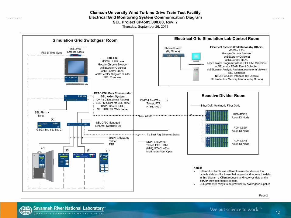
eGrid Overview One-Line
13

eGrid Reactive Divider Network Controls
14

Relay Information and Data Server Tags
Example Relay Information OPC Server Tags RELAY : SEL-751A
Type Inde x Point ID Description Uni ts Val ue Type AI 0000 IA_MAG A-Phase Line Current Amps REAL AI 0001 IB_MA G B-Phase Line Current Amps REAL AI 0002 IC_MA G C-Phase Line Current Amps REAL AI 0003 IN_MAG Ne utral Curre nt Amps REAL AI 0004 IG_MAG Residual Current Amps REAL AI 0005 IAV Average Line Current Amps REAL AI 0006 UBI Current Unballance % REAL AI 0007 IARMS A-Phase RMS Current Amps REAL AI 0008 IBRMS B-Phase RMS Current Amps REAL AI 0009 ICRMS C-Phase RMS Current Amps REAL AI 0010 INRMS Ne utral RMS Curre nt Amps REAL AI 0011 VA_MAG A-Phase to Ne utral V ol tage Vol ts REAL AI 0012 V B_MAG B-Phase to Neutral Voltage Volts REAL AI 0013 V C_MAG C-Phase to Neutral Voltage Volts REAL AI 0014 VAB_MAG A to B Phase Voltage Vol ts REAL AI 0015 V BC_MAG B to C Phase Vol tage Vol ts REAL AI 0016 VCA_MAG C to A Phase Voltage Vol ts REAL AI 0017 VAVE Average V ol tage Vol ts REAL AI 0018 UBV Voltage Unbalance % REAL AI 0019 V ARMS A-Phase RMS Voltage Vol ts REAL AI 0020 V BRMS B-Phase RMS Vol tage Vol ts REAL AI 0021 V CRMS C-Phase RMS Vol tage Vol ts REAL AI 0022 V ABRMS A to B Phase RMS Voltage Volts REAL AI 0023 V BCRMS B to C Phase RMS Vol tage Vol ts REAL AI 0024 V CARMS C to A Phase RMS Voltage Volts REAL AI 0025 SA A-Phase Apparent Power kVA REAL AI 0026 SB B-Phase Apparent Power kVA REAL AI 0027 SC C-Phase Apparent Power kVA REAL AI 0028 S 3-Phase Apparent Power kW REAL AI 0029 PA A-Phase Real Power kW REAL AI 0030 PB B-Phase Real Power kW REAL AI 0031 PC C-Phase Real Power kW REAL AI 0032 P 3-Phase Real Power kW REAL AI 0033 QA A-Phase Reactive Power kVAR REAL AI 0034 QB B-Phase Reactive Power kVAR REAL AI 0035 QC C-Phase Reactive Power kVAR REAL AI 0036 Q 3-Phase Reactive Power kVAR REAL AI 0037 PF 3-Phase Power Factor Pe r Uni t REAL AI 0038 FREQ Frequency HZ REAL AI 0039 WEARA Breake r Wear, A-Phase % REAL AI 0040 WEARB Breake r Wear, B-Phase % REAL AI 0041 WEARC Breake r Wear, C-Phase % REAL
DNP
15

LabView Program Reads Data From Kepware and Transfers to the Data Acquisition System
1st data point is the timestamp which is synchronized with other data acquisitions in the facility with a GPS timestamp
16

Relay Communication Status
17

Primary Team Members
Clemson University – Dr. Curtiss Fox ([email protected])
Savannah River National Laboratory – Joe Cordaro ([email protected])
National Instruments – Jeff Tipps ([email protected])
Schweitzer Engineering Laboratories – Gary Pederson ([email protected])
18