the eureka electric clock - model engineer€¦ · · 2009-10-21the " eureka " electric...
TRANSCRIPT


The " Eureka " Electric Clock
by " Artificer "
TH E construction of electrically-driven clockshas always;been popular among model
engineers, and at nearly every ModelEngineer Exhibition, at least one or two speci-mens of these clocks are represented. But whilethe workmanship (and presumably, the per-formance) of these clocks is often extremelvgood, and some of them exhibit originality andingenuity in the details of design, there is com-paratively little enterprise among constructors inexploring the broad principles of design, and inutilising the many possible forms of escapementsand operating mechanisms which have beendevised in the past. It is safe to say that about
95 per cent. of the electric clocks which havebeen built by amateurs have been either of theHipp or the Synchronome types, with minormodifications in each case ; and while boththese embody unquestionably sound workingprinciples, and if properly made, work mostreliably and keep accurate time, there is a strongcase for going farther afield and introducing alittle more variety in this branch of construction.
The obvious answer which many amateurconstructors will make to this criticism is that thetwo types of clocks mentioned above are the onlyones on which any detailed information onconstruction is available. This is-quite true ; of
The “ Eureka ” clock movement viewed from the rear, showing regulator star wheel
123

THE MODEL ENGINEER
two books on building electric clocks which thewriter obtained some years ago, one described anumber of different sizes and styles of clocks allusing the Hipp escapement, while the other dealtwith several Hipp clocks plus one Synchronomemaster and secondary clock. A third bookdescribed in detail the construction of a single
I --4-
Fig. I. Position of balance wheel when at rest
Hipp clock, while several articles published inT H E M O D E L E N G I N E E R and other journalsplayed minor variations on the same old theme.It is in the hope of broadening general knowledgeof the working principles of electric clocks,therefore, that the following particulars aregiven of a type of clock which is notabl y “ differ-ent,” and despite the fact that it is not claimed tobe superior in any way to the popular types ofelectric clocks, is none the less interesting to theenterprising constructor.
It may further be noted that practically all theelectric clocks built by amateurs-with theexception of a.c. mains synchronous clocks,which, one might argue, are ndt really clocks at all-have so far been pendulum clock s ; and whilethere is nothing one can object to about suchclocks from the timekeeping point of view, thereis no doubt that they have their own particularlimitations. The normal form of pendulum isimpracticable in any type of portable clock, andif one had to rely exclusively on it, timekeeping atsea would be impossible unless the clock couldbe held steady by an elaborate gyroscopic stabilis-ing device. While no form of balance wheel isquite equal in isochronous property to the bestform of pendulum, it can be designed so as toshow no perceptible inferiority in practice, and
124
FEBRUARY 3. 1949
it can be compensated for climatic and othervariations just as readily as a pendulum.
The balance wheel has been successfullyapplied to a number of electrically-driven clocks,including some small portable clocks such asthose for use in cars or other vehicles. It may,however, be noted that most of the latter may beregarded as more or less normal mechanicalspring-driven clocks, equipped with an electricimpulse device to wind the spring at regular(and usually frequent) interval s ; in other words,they come into a class terme d “ Remontoir e ”(self-winding) electric clocks, which presentlittle real interest from the constructor’s point ofview.
There is, however, at least one notable exampleof a balance-wheel electric clock in which thedriving impulse is applied directly to the balancewheel so that, like the pendulum of the Hippand Synchronome clocks, it constitutes the actualdriving “ motor,” and transmits power to thewheel train, which serves the function of an impulse counter and indicating mechanism,rather than a heavily-stressed transmission gear.Herein lies the great advantage of the trueelectrically-driven clock from the aspect of theamateur constructor ; the pendulum or balancewheel, together with its escapement, instead ofbeing a delicate and finely-poised piece of
L---iL--. _.--.._- j lrlFig. 2. Position of balance wheel at the point of
making contact
mechanism, the adjustment of which demandsspecialise d skill, is heavy and robust, requiringcomparatively little finesse in either constructionor adjustment. This does not mean to say thatthere is not just as much scope for skill and carein the construction of such clocks as in those of

THE MODEL ENGINEER FEBRUARY 3, 1949
the weight- or spring-driven type ; but it is a production was abandoned after about five years.fact that some excellent results have been ob- There were possibly several reasons for this, nottained with electric clocks of quite unsophisticated the least being that inevitable teething troublesor even crude design and construction. were encountered in the early stages of produc-
The “Eureka ” electric clock, which forms the tion, and it is more than likely that when such
Front view of “ Eureka” clock movement, with dial removed to show gear train and ratchet lever
subject of these articles, was invented in 1906, andwas put into production by the enterprise of thebrotherssKutnow, of “ Kutnow’s Powder ”fame. Its novel and somewhat spectaculardesign attracted a good deal of attention at thetime, but it proved to be a nine day’s wonder, and
faults as developed were referred to clockrepairers, the unfamiliar nature of the mechanismprejudiced their chances of receiving conscien-tious attention. The examples of these clockswhich have been encountered, or on whichinformation is available, bear evidence of un-
125

THE MODEL ENGINEER
finished design or tentative experiment, and thereare certainly one or two points where the designor workmanship could be much improved. Butthe clock can at any rate be made to work welland reliably with a very low current consumption,and its inherent timekeeping qualities, thoughby no means perfect, are probably as good asthose of most domestic and portable clocks ofthe normal type.
Some time ago,the writer wasconsulted aboutthe repair and res-torat ion o f a" Eureka ” clock‘which had beenout of use formany years, and- thanks to theministrations ofsomeone who hadtinkered with itat some time in
FEBRUARY 3, 1949
pension of the balance is by extended pivotswhich roll on steel balls enclosed in an oil bath.
An iron bar, A, passes diametrically across thebalance wheel, forming the “ spokes ” on whichthe rim is supported ; this is wound with a coilof wire so that it forms an electro-magnet whenenergised with current from a battery. Thesupply of current is controlled by a contact
d e v i c e w h i c hcloses the circuitat the appropriatetime. Below thebalance wheel isa stationary ironplate, D, m a c h -ined away in thecentre so as top r o v i d e a f i n eclearance for the
NCtips of the bar as
c, the wheel oscil-CT). lates.
When the clockthe past -had is at rest, the barseveral essential Fig. 3. Action of contact spring on both directions of balanceparts of the mech- wheel movement
assumes a perpen-dicular position
anism missing. relative to the ironThere was, in fact, no visible link-up between thebalance-wheel “ motor ” and the gear train, andthough it was not difficult to reconstruct thegeneral design of the missing parts, it wasdecided that it would be worth while to consultany available information on the original con-struction of the clock. In the course of thisresearch, which entailed the consulting of all thebooks on electric clocks which could be unearthed(and incidentally some of them contained totallymisleading information, worse than none at all !)and enquiries at South Kensington Museum(much more fruitful) a certain amount of data onthis and other unusual types of electric clocks hasbeen acquired. Some further advice has beengiven on this matter by Mr. F. Hope- Jones, who,as most readers are aware, is a world authorityon electric clocks ; and as a result, the restorationof the clock in question has been very successfullycarried out. In the hope that the matter will beof interest to many readers? an exact record of thedesign and working details of the clock in itsrestored form has been prepared, with somesuggestions for possible improvement of thedesign and methods of construction.
Working Principle of the ,“ Eureka ” ClockThe motive power of the clock is obtained from
a large diameter oscillating balance wheel, thegeneral form of which is similar to that of awatch balance on an enlarged scale, including thehair spring. This’ wheel is kept in motionby an electro-magnetic device which operates onthe same principle as that in any simple attractionmotor. It may here be mentioned that in aclock having the motive power supplied by thependulum or balance, a fairly substantial massin the latter is most essential. In this case, thebalance wheel is 12 oz. in weight, and the dia-meter over the rim is 2-7/8 in., the outermostdiameter over the complete balance system being3-3/4 in. The rim is of the bimetal compensatedtype, and fitted with poise screws ; the sus-
126
plate, as shown in Fig. I. The contact pin, B, inthe cheek of the balance wheel is just clear of thecontact spring, C, so that no current is passing,and the electro-magnet is inert. It will be notedthat the contact pin, D, is composed of two half-round sections, the one on the left being of metaland the other of insulating material. The spring,C, has an attached tip of contact metal(usually gold-silver alloy), extending sideways, sothat the end is shaped like an inverted L. It isadjusted in such a way that the contact pin passeson the right-hand side of it on the upwards swing(see Fig. 3A) and on the left-hand side of it on thedownward swing as shown in Fig. 3B ; thespring being in each case displaced slightly inthe opposite direction. The metal part of thecontact pin forms the terminal point at one end ofthe magnet winding, the other being earthed tothe frame of the wheel, and making connectionwith the main motion frame through the hairspring. Current is supplied from the battery byconnecting one terminal to the base of the contactspring and earthing the other to the frame.
If the balance wheel is now set oscillating byhand, the first swing in the anti-clockwisedirection will carry the contact pin past the springwith its insulated portion in contact, so that nocurrent passes. But on the return (clockwise)swing, when the position shown in Fig. 2 isreached, the contact pin will again touch thespring, this time on the metallic side, so that aconnection is established through the windings ofthe electro-magnet, which becomes stronglyenergised, just as its tip is approaching the con-cave portion of the iron plate. The result is tocause a powerful attraction of the electro-magnetto the centre of the plate, but by the time itreaches this point, contact will be broken betweenthe pin and the spring, so that the balance wheelwill continue to move under its own inertia untilthis is counteracted by the hair spring. Thisstarts it on the return swing, and the cycle of
(Continued on page 130)

THE MODEL ENGINEER
Outside HelpThere is no doubt
that the key to goodmodel making is know-ing the right tools andknowing how to usethem. Of course,methods will varyaccording to the facili-ties at hand, but themodel engineer shouldnot close his eyes tooutside help. He mayspend hours shapingparts which could bedone much better andquicker if the rightequipment was avail-able, and this can oftenbe had by joining orforming. an association
Fig. 10. A fabricated connecting-rod, made by welding steel tube to rod
and making use of a common workshop. Theworkshop would contain such items as a weldingplant, and equipment for brazing and machining.Falling this kind of self-help? in most townsthere are several small engineering concernswho would carry out welding and machiningoperations which are outside the scope of theindividual.
FEBRUARY 3, 1949
The use of weldingfor the modelmakershould not be over-looked. Welding hasmade great strides ingeneral engineeringwhere parts which tookmany weeks to make,can now be made in amatter of hours. Thisis due to “ fabrica-tion.” Take for in-stance a model connect-ing-rod ; instead ofmaking this out of onepiece, two short piecesof steel tube are weldedto each end of a pieceof steel rod, the endsthen trued up andreamed. (see Fig . IO) .
This is a much quicker way and can be lust asgood in every aspect. There are many partswhich at one time had to be cast or forged andare now made by welding several pieces together.This method is invaluable in model making, forit often happens that it is a one off job, in whichcase pattern making and casting is a slow andexpensive job.
The “Eureka ” Electric Clock(Continued from page 126)
events is then repeated indefinitely, so long ascurrent is available to energise the magnet.
It will be quite clear that an essential feature inthe function of the clock is that current must onlybe supplied during the time the magnet isapproaching the centre of the iron plate? thereforecontact must only be made on one direction ofswing. If contact took place on the reverseswing, it would produce an impulse equal andopposite to the first, tending to stop the motionof the wheel. This point is emphasised becauseit has been stated by one writer in a publisheddescription of the ‘(Eureka” clock that impulsetakes place in both directions of swing ; astatement which caused considerable perplexitywhen the working of this clock was first investi-gated by the writer, until it was proved that suchaction was quite impossible with the form ofcontact mechanism shown.
The strength of the impulse will be dependenton the e.m.f. supplied by the battery, so that anyvariation in the voltage, as caused by a gradualrunning down or deterioration will affect theapplied power, and to some extent, the rate of thebalance. But the isochronous characteristics ofthe latter will be similar to those of an ordinarywatch balance, which tends to compensatevariations of power by altering the arc of itsswing, and timekeeping errors from this sourceare not serious, unless one insists on high pre-cision standards. It would not be impossible,
130
however, to improve on this detail, and introducea constant-impulse form of contact device if sodesired.
So far, only the operation of the balancewheel “motor” has been considered, butobviously some method of “ counting ” theimpulses of the wheel and using them to drivethe hands of the clock is essential. The geartrain employed for this purpose differs in nopractical respect from that of an ordinary clock,but what would normally be the escape wheel is inthis case a ratchet wheel, which is fed one toothat a time by a lever and pawl deriving its motionfrom the balance wheel system. This is done byproviding an eccentric on the staff of the balancewheel, and a large diameter roller resting on thelatter, and mounted on a pivot at one end of thelever. The ratchet mechanism is clearly visiblein the photograph taken from the front side of theclock, with the dial removed ; this part of theclock is of course essentially similar to that of theHipp, Synchronome and many other electricclocks.
The balance wheel is regulated by the usualmethod of controlling the free length of the hairspring, a rather elaborated geared quadrant beingfitted for this purpose, and operated from a pinionwith a star wheel on the outside of the motionplate, as seen in the photograph taken from therear side.
(To be continued)
* The " Eureka " Electric Clock
by " Artificer"
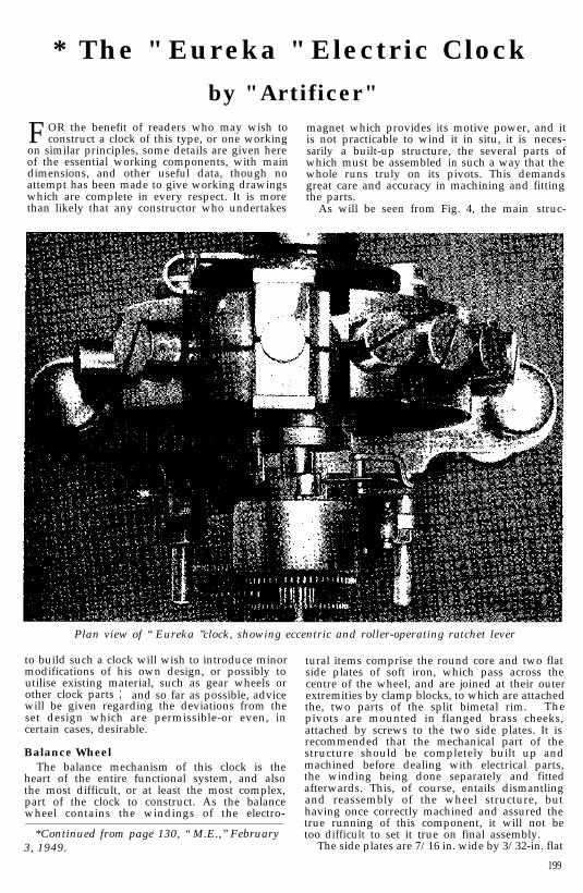
FOR the benefit of readers who may wish toconstruct a clock of this type, or one working
magnet which provides its motive power, and it
on similar principles, some details are given hereis not practicable to wind it in situ, it is neces-
of the essential working components, with mainsarily a built-up structure, the several parts of
dimensions, and other useful data, though nowhich must be assembled in such a way that the
attempt has been made to give working drawingswhole runs truly on its pivots. This demands
which are complete in every respect. It is moregreat care and accuracy in machining and fitting
than likely that any constructor who undertakesthe parts.
As will be seen from Fig. 4, the main struc-
Plan view of “ Eureka ”clock, showing eccentric and roller-operating ratchet lever
to build such a clock will wish to introduce minormodifications of his own design, or possibly toutilise existing material, such as gear wheels orother clock parts ; and so far as possible, advicewill be given regarding the deviations from theset design which are permissible-or even, incertain cases, desirable.
Balance WheelThe balance mechanism of this clock is the
heart of the entire functional system, and alsothe most difficult, or at least the most complex,part of the clock to construct. As the balancewheel contains the windings of the electro-
*Continued from page 130, “ M.E.,” February3, 1949.
tural items comprise the round core and two flatside plates of soft iron, which pass across thecentre of the wheel, and are joined at their outerextremities by clamp blocks, to which are attachedthe, two parts of the split bimetal rim. Thepivots are mounted in flanged brass cheeks,attached by screws to the two side plates. It isrecommended that the mechanical part of thestructure should be completely built up andmachined before dealing with electrical parts,the winding being done separately and fittedafterwards. This, of course, entails dismantlingand reassembly of the wheel structure, buthaving once correctly machined and assured thetrue running of this component, it will not betoo difficult to set it true on final assembly.
The side plates are 7/16 in. wide by 3/32-in. flat
199
THE MODEL ENGINEER FEBRUARY 17, 1949
strip, and the core piece 5/16 in. diameter roundbar, specified as soft iron, but as it may be some-what difficult to obtain the Swedish “ charcoaliron,” which is generally represented as the idealin the electrical text books, it may be mentionedthat mild-steel has been found to work quitewell for small electro-magnets in which highpermeability and minimum retention of mag-netism are essential properties. To ensure thatit is as soft as possible, it is advisable to take theprecaution of annealing it, which in the absenceof a muffle or other heat-treatment equipment, isbest done by packing the material inside a pieceof iron pipe, in lime or ashes, with iron or clayplugs in the ends, and heating the lot up to abright red, sustaining the temperature for severalminutes and then allowing it to cool off naturally.The traditional use of the kitchen stove, and theall-night period of cooling, cannot be improvedupon for this operation.
temporary screws or dowels in the holes, whilethis is being done.
Next dismantle the parts again, and set up theone side plate, with the blocks clamped thereto,on the faceplate for machining the inner concavesurface of the blocks to fit the rim of the balancewheel. The centre hole in the plate, for the inser-tion of the pivot, must be set dead true, and tofacilitate this, a temporary plug may be insertedin the mandrel socket and turned down in placeto form a close-fitting pilot or spigot. If thesweated joint is relied upon to hold the clampblocks, very light cuts should be taken on thelatter to avoid the risk of their becoming detached ;but this risk can be very much reduced if tem- *porary screws are used in the clamp screw holes,and further security may be provided, if desired,by dowelling the blocks in position as well.
The Bimetal RimBy heating the metal in an enclosed chamber
so that it is protected from the atmosphere, littleor no scaling or pitting of the surface should takeplace, but the metal should in any case be cleanedup, and trued if necessary, before proceedingfurther. It may here be mentioned that it wouldbe an advantage, from the structural point ofview to modify the shape of the side plates,making them at least as wide as the diameter ofthe brass cheeks (7/8 in.) in the centre, and taperingoff to 7/16in. wide at each end. This would allowof using three screws for securing each of thecheeks. Better still, the plates may be madewider ‘in the centre than the diameter of thecheeks, and thick enough to allow of turning arecess to register tightly over the latter, therebyimproving the rigidity of the assembly consider-ably. Leave a small allowance on the length ofthe plates for finishing.
As most readers with horological knowledgeare aware, the object of using a split rim made oftwo dissimilar metals for the balance wheel of aclock or watch is to compensate for temperatureerrors in timekeeping. The principle is exactlythe same as the bimetal strip used in thermostatsand “ biinkers ” as extensively used in electricalapparatus, and it is probable that the idea ofthese devices was evolved from the methodswhich had long been used by horologists.
Mark out the positions of the centre pivotand the two clamping screws on one of the plates,taking great care to ensure symmetry in bothplanes, and drill undersize pilot holes ; thesecond plate is jig drilled from the first, andmarked to show relative positions for subsequentlocation. Next make the two clamp blocks, onein iron and the other in brass ; their final dimen-sions are 3/8in. by 7/16 in. by 13/16 in., but they arebest left oversize on all dimensions at first. Setup each in turn in the four-jaw chuck, crosswise,and drill and ream to a tight wringing fit on theround core piece ; if the only reamer availableproduces too easy a fit, it is worth while to makea slightly undersize D-bit from silver-steel forthis purpose. Press both the blocks on to amandrel, or on the core itself, and finish the endfaces by filing or machining so that they areexactly parallel to the mandrel and equal indistance from it on each side.
If the rim of a balance wheel is made of solidmetal, it is, of course, subject to expansion andcontraction with any change of temperature,and thus minute alteration of its diameter takesplace, involving similar changes in its radialcentre of gravity, or in other words, the momentof its mass. The ultimate result will be that anincrease of temperature will tend to slow theclock down, and a decrease of temperature willspeed it up. This effect might be very muchreduced by making the rim of a metal having avery low coefficient of expansion, such as Invarsteel ; but long before metallurgists had bitupon this solution, the problem had been dealtwith in another way by the ingenious makers ofclocks and watches.
The blocks should now be set in their correctpositions *between the side plates, with the corepiece in position and the holes for the clampingscrew drilled through clamp blocks and core,but not to finished size at this stage. Remove theblocks, and tin one end face of each, also themating surfaces on one of the plates, and sweatthem in position ; note that this must be done onone plate only as the other must always becapable of removal. The assembly should beclamped together, with the core in place, and
In the normal “ compensated balance.” therim is made of two metals which have definitely(not necessarily widely) different coefficients ofexpansion, the one having the greater expansionbeing on the outside. Brass and steel arecommon metals conforming to this condition,and are commonly used. The rim is supportedby radial spokes, not more than two or threein most cases, and is split near each spoke, sothat the composite rim is virtually in separatesections, each forming a curved strip of the twometals in close intimate metallic contact. Whenchanges of temperature take place, expansionor contraction of the spokes of the wheel alterthe moment of mass of the rim at the point ofsupport, but this is counteracted by the behaviourof the bimetal rim sections, which alter theircurvature by reason of the differential expansionof the two metals. As the spokes of the wheelexpand radially outwards, the free end of the rimcurves inwards, and if the wheel is suitablydesigned, the result is to produce a reasonablyexact temperature compensation within the rangenormally encountered.
200
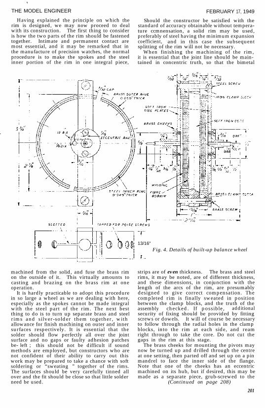
I THE MODEL ENGINEERIi Having explained the principle on which the, rim is designed, we may now proceed to deal
with its construction. The first thing to consider.! is how the two parts of the rim should be fastened
together. Intimate and permanent contact aremost essential, and it may be remarked that inthe manufacture of precision watches, the normalprocedure is to make the spokes and the steelinner portion of the rim in one integral piece,
FEBRUARY 17, 1949
Should the constructor be satisfied with thestandard of accuracy obtainable without tempera-ture ccmnensation, a solid rim may be used,preferably of steel having the minimum expansioncoefficient, and in this case the subsequentsplitting of the rim will not be necessary.
When finishing the machining of the rim,it is essential that the joint line should be main-tained in concentric truth, so that the bimetal
machined from the solid, and fuse the brass rimon the outside of it. This virtually amounts tocasting and brazing on the brass rim at oneoperation.
It is hardly practicable to adopt this procedurein so large a wheel as we are dealing with here,especially as the spokes cannot be made integralwith the steel part of the rim. The next bestthing to do is to turn up separate brass and steelrims and silver-solder them together, withallowance for finish machining on outer and innersurfaces respectively. It is essential that thesolder should flow perfectly all over the jointsurface and no gaps or faulty adhesion patchesbe- left ; this should not be difficult if soundmethods are employed, but constructors who arenot confident of their ability to carry out thiswork may be prepared to take a chance with soft
1 soldering or “sweating ” together of the rims.The surfaces should be very carefully tinned allover and the fit should be close so that little solderneed be used.
-r--/13/16"
j Fig. 4. Details of built-up balance wheeli-
strips are of even thickness. The brass and steelrims, it may be noted, are of different thickness,and these dimensions, in conjunction with thelength of the arcs of the rim, are presumablydesigned to give correct compensation. Thecompleted rim is finally sweated in positionbetween the clamp blocks, and the truth of theassembly checked. If possible, additionalsecurity of fixing should be provided by fittingscrews or dowels. It will of course be necessaryto follow through the radial holes in the clampblocks, into the rim at each side, and reamright through to take the core. Do not cut thegaps in the rim at this stage.
The brass cheeks for mounting the pivots maynow be turned up and drilled through the centreat one setting, then parted off and set up on a pinmandrel to face the inner side of the flange.Note that one of the cheeks has an eccentricmachined on its hub, but if desired, this may bemade as a separate piece, grub-screwed to the
(Continued on page 208)
201
THE MODEL ENGINEER FEBRUARY 17, 1949
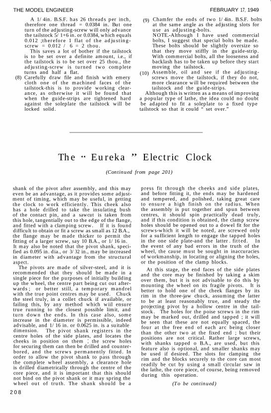
A 1/4in. B.S.F. has 26 threads per inch,therefore one thread = 0.0384 in. But oneturn of the adjusting-screw will only advancethe tailstock 5/1+6 in. or 0.0384, which equals0.012 ;therefore 1 flat of the adjusting-screw = 0.012 / 6 = 2 thou.
(9)
This saves a lot of bother if the tailstockis to be set over a definite amount, i.e., ifthe tailstock is to be set over 25 thou., theadjusting-screw is turned two completeturns and half a flat. (10)
(8) Carefully draw file and finish with emery
Chamfer the ends of two 1/4in. B.S.F. boltsat the same angle as the adjusting slots foruse as adjusting-bolts.NOTE.-Although I have used commercialbolts, I suggest that special bolts be made.These bolts should be slightly oversize sothat they move stiffly in the guide-strip.With commercial bolts, all the looseness andbacklash has to be taken up before they startmoving the tailstock.Assemble, oil and see if the adjusting-screws move the tailstock, if they do not,more clearance will be required between thetailstock and the guide-strips.
cloth one of the machined faces of thetailstock-this is to provide working clear-ance, as otherwise it will be found that Although this is written as a means of improvingwhen the guide-strips are tightened hard a popular type of lathe, the idea could no doubtagainst the soleplate the tailstock will be be adapted to fit a soleplate to a fixed typelocked solid. tailstock so that it could “ set over.”
The “ Eureka ” Electric Clock(Continued from page 201)
shank of the pivot after assembly, and this mayeven be an advantage, as it provides some adjust-ment of timing, which may be useful, in gettingthe clock to work efficiently. This cheek alsohas a hole drilled to take the insulating bushof the contact pin, and a sawcut is taken fromthis hole, tangentially out to the edge of the flange,and fitted with a clamping screw. If it is founddifficult to obtain or fit a screw as small as 12 B.A.,the flange may be made thicker to permit thefitting of a larger screw, say 10 B.A., or 1/16 in.It may also be noted that the pivot shank, speci-fied as 0.095 in. dia., or 3/32 in., may be increasedin diameter with advantage from the structuralaspect.
The pivots are made of silver-steel, and it isrecommended that they should be made in asingle piece for the purposes of initially buildingup the wheel, the centre part being cut out after-wards ; or better still, a temporary mandrelwith the true point centres may be used. Chuckthe steel truly, in a collet chuck if available, orfailing this, by any method which wiil ensuretrue running to the closest possible limit, andturn down the ends. In this case also, someincrease in the diameter is permissible, indeedadvisable, and 1/16 in. or 0.0625 in. is a suitabledimension. The pivot shank registers in thecentre holes of the side plates, and locates thecheeks in position on them ; the screw holesfor securing them can then be drilled and counter-bored, and the screws permanently fitted. Inorder to allow the pivot shank to pass throughthe complete wheel assembly, a clearance holeis drilled diametrically through the centre of thecore piece, and it is important that this shouldnot bind on the pivot shank or it may spring thewheel out of truth. The shank should be a
2 0 8
press fit through the cheeks and side plates,and before fitting it, the ends may be hardenedand tempered, and polished, taking great careto ensure a high finish on the radius. Whenthe assembly is put together and spun betweencentres, it should spin practically dead truly,and if this condition is obtained, the clamp screwholes should be opened out to a dowel fit for thescrews-which it will be noted, are screwed onlyfor a sufficient length to engage the tapped holesin the one side plate-and the latter . fitted. Inthe event of any bad errors in the truth of thewheel, the cause must be sought in inaccuraciesof workmanship, in locating or aligning the holes,or the position of the clamp blocks. _
At this stage, the end faces of the side platesand the core may be finished by taking a skimover them, but it is not advisable to do this bymounting the wheel on its fragile pivots. It isbetter to hold one of the cheek flanges by itsrim in the three-jaw chuck, assuming the latterto be at least reasonably true, and steady theprojecting pivot by a hollow centre in the tail-stock. The holes for the poise screws in the rimmay be marked out, drilled and tapped ; it willbe seen that these are not equally spaced, thefour at the free end of each arc being closerthan the other two at the fixed end ; but theirpositions are not critical. Rather large screws,with shanks tapped o B.A., are used, but thisfeature also is optional, and smaller shanks maybe used if desired. The slots for clamping therim and the blocks securely to the core can mostreadily be cut by using a small circular saw inthe lathe, the core piece, of course, being removedduring this operation.
’
(To be continued)

*The“ Eureka ”Electric Clockby “ Artificer ”
HAVING completed the building-up of thebalance wheel, the electrical components
incorporated in this unit may be considered. Thecontact pin assembly, shown in detail in Fig. 5,
comprises a fibre or bakelite bush turned to fitthe split clamp in the wheel cheek, and drilled1/16 in. through the centre to take the half-roundpieces of metal and insulating material, which
from tube, with end washers cemented on, if thisis more convenient. The thickness of the tube
Fig. 5, Details of contact-pin assembly
should fit fairly tightly, but not so as to riskbursting the bush. A piece of 16-gauge silverwire is recommended for the contact pin, but ifnot available, nickel-silver (german silver) willgive fairly good results. It should be carefullyfiled to a half-round section, using a micrometerto gauge when exactly half the diameter has beenfiled away.
A piece of glass or quartz rod 1/16 in. diameteris the most suitable material for the insulatingside of the pin ; this may be ‘obtained from ashop dealing in laboratory glassware, and afterthe required length is cut off by nicking with afile, it should be embedded in a pitch block andground down flat on one side on a metal or glasslap charged with carborundum paste. As it maybe difficult to gauge exactly how much materialhas been removed in this case, it may be advisableto do this before making the metal part, andadjust the thickness of the latter to sun. Ifvitreous material is considered too difficult towork, the next best substitute is a piece of hardplastic material, such as a knitting needle, whichis first turned down to the required diameter andthen filed half-round. Adhesion between theprojecting ends of the metal and insulation canbe obtained by the use of a. cement such asDurofix, or by melting in a flake of shellac.When fitted to the bush, and the latter clampedin place in the cheek of the wheel, the pin shouldbe quite secure. The inner end of the metalportion should be bent outwards as shown toform a convenient solder tag for connecting theouter end of the magnet coil.
Winding the CoilA bobbin for the coil should be prepared,
preferably by turning from the solid in ebonite,fibre or bakelite, though it may be fabricated
*Continued from page 208, “ M.E.,” February17, 1949.
250
and end cheeks should not be more than 1/16 in.;and the bobbin should be a free sliding fit on thecore, its overall length being adjusted to fitneatly inside the rim of the balance wheel.
The magnet coil of the clock examined had aresistance of just over 20 ohms, which represents
Fig. 6. Poise screws (12 off)
about four layers of No 24 gauge wire. In thewriter’s opinion, a coil of higher resistance wouldbe an advantage, as the power obtained from themagnet on an input of 1-1/2 volts appears to begreater than is necessary to maintain the swingof the wheel, and is liable to affect the accuracy oftimekeeping. The higher resistance would alsoimprove economy of current consumption, withlonger battery life and less variation of voltage.It will be noted that most battery-driven clocksin which the impulses are frequent, work bestwith magnets of high resistance. There is plentyof space in the balance wheel for considerablymore turns of the same gauge wire, or, alter-natively, a smaller gauge of wire may be usedto increase the resistance.
The wire may be either enamel, cotton or silkcovered, and the process of winding it is quitesimple ; it may be carried out either in the lathe,drilling machine, or on a hand-driven spindle.There are not enough turns on the coil to makewinding tedious. Care should be taken in layingthe turns so as to ensure neat and even winding,which, although not important from the electricalaspect, affects the balance of the wheel, as well asits appearance.
The first layer of a coil is always easy enough tolay evenly, but difficulty is often encounteredwith subsequent layers owing to the slipping ofend turns. If this trouble arises, a layer of stiffpaper or Empire cloth may be interposed betweenthe layers of wire ; it should be cut to fit thelength of the bobbin closely and with a moderateoverlap, so that it can be cemented down withDurofix or shellac varnish. When the coil iscompleted, it should be well varnished externally,the object being not so much to improve insula-tion, which is not at all highly stressed, in viewof the low operating voltage, as to fix the turnsmechanically and prevent them moving after-wards. The end turn may be tied in place withsilk or cotton thread.

THE MODEL ENGINEER
To assemble the wound bobbin in place, it is,of course, necessary to remove one side of thebalance wheel and slide out the core piece ; ifthe pivot has been made in one piece to serveas a mandrel when building up the wheel, itscentre must, of course, be cut out to allow thebobbin to be fitted. If there is any end play ofthe latter inside the rim of the wheel, paper washers should be cemented to the side cheeks totake this up ; no movement of the bobbin is
MARCH 3, 1949
Poise ScrewsWhen the complete balance wheel is assembled
and spun on its pivots, it should run truly and befairly well balanced. Any error in this respectshould be corrected before going further ;assuming this is in order, however, the rim maynow be split in two places, as shown in Fig. 4.The width of the gap is not critical, but the sameamount of metal should be removed in each case,to maintain proper balance.
I .J-.- I
IFig. 7. Armature plate’
permissible when the wheel is assembled. Theinner end of the coil winding is connected, bysoldering or other convenient method, to thewheel structure, and the outer end soldered to thebent inner end of the contact pin. The arrange-ment of the core piece and side plates, with asingle iron clamp block at one end, and the woundbobbin on the core, constitutes a three-limbed or“ trident ” form of electro-magnet. Assumingthe tip of the core, at the end remote from theiron clamp piece, to be a N pole, the adjacentends of the side plates will both be S poles. Thisconstitutes a highly efficient form of magnet,and when working in close proximity to thearmature plate, as it normally should, the systemis completely “ ironclad,” so that there is prac-tically no stray field to reduce efficiency or causetrouble by magnetisation of the hair-spring. Atest of the magnet, by connecting a single drycell between the contact pin and the balance-wheel frame, should show a powerful attractiveforce when a piece of iron is held near the openpoles, with a curent flow of about 75 milliampsat this voltage input.
The fitting of poise screws is not absolutelyessential, though it is usual in a compensatedbalance wheel. Both the balancing and thenatural period of the wheel are influenced by thepoise s c r e w s ; they may be used to affect therating or regulation of the clock, but their mostuseful function in the case of watches is thecorrection of position errors-that is to say,variation of timekeeping accuracy according tothe position and angle of the watch frame. Inthe case of the “ Eureka ” clock, in which theposition of the balance wheel axis is not likely tovary, this condition does not arise ; but theweight and location of the poise screws alsoaffects the period in relation to the arc of balancewheel swing. Adjustment in this respect may bevery useful, though not easy to apply in practiceunless one is an experienced horologist.
It will be seen from the photographs that thepoise screws are not screwed fully home againstthe rim of the wheel, and in view of the fact thatthe shanks of the screws are split to provide afriction grip in the tapped holes, it can beassumed that they were definitely intended to be
251

THE MODEL ENGINEER
adjusted in this way. This is, however, contraryto the best watch practice, where the screws arefully tightened, and adjustment of balance ormoment made by filing the screw heads, or, con-versely, fitting ballast washers under them.
The detail drawing of the poise screws, Fig. 6,shows that an annular groove is machined in theunderside of the head, which may possibly havebeen intended for ballasting with lead or similar
MARCH 3, 1949
either of brass or steel attached underneath. Thelatter have flats filed or milled to a depth prac-tically equal to the thickness of the plate, andfitting tightly over the edges of it, so that onescrew in each stud will hold it securely. At theends of the plate, holes are drilled for the screwsor studs which secure the vertical pillars by whichthe entire movement is mounted on its plinthor bedplate.
LEAR
Fig. 8. Rear motion plate
material. As this groove will require a specialtool to machine, it may be omitted and the screwhead shortened to compensate for the increasedweight. All the poise screws, twelve in number,should be of equal weight, and should be adjustedin the rim so that the balance wheel will rest inany position when poised on knife-edges.
The hair-spring may ‘be made from a main-spring of a small watch. It consists of approxi-mately 12-1/4 turns, the material being spring steel0.096 in. wide by 0.015 in. thick. The centre ofthe spring is attached to a brass collet by swaginginto a tangential sawcut, and the collet is mountedon the arbor with a 14-B.A. grub screw, which isconvenient for setting the balance correctly inbeat. If desired, however, the usual friction-tightsplit collet may be fitted.
Armature PlateThis is made from annealed iron or mild steel,
and forms not only the armature but also thefoundation plate of the clock movement. Asshown in Fig. 7, it is 1-1/4 in. wide in the centralportion, and 9/64 in. thick, with pillar studs made
252
It will be seen that the centre portion of theplate is machined to an arc corresponding to theradius of the balance wheel pole tips, plusclearance. This can be machined with a cutterheld in a boring bar between lathe centres, theplate being clamped vertically to an angle-platemounted on the lathe cross-slide, with its centrelevel with the lathe axis. In a small lathe, it willbe found necessary to overhang the work to oneside of the cross-slide to obtain necessary clearance.
The amount of metal to be removed here isquite small, and it is doubtful whether machiningsuch a short arc has much effect on the magneticefficiency as compared with a plain flat plate. Inthe event of difficulty in machining this surface,it is fairly certain that the clock will work satis-factorily with the plate left flat, so long as theworking clearance of the pole tips of the balancewheel is suitably adjusted.
Rear Motion PlateBoth the motion plates of the “ Eureka ” clock
are made from brass castings, but they may befabricated by silver-soldering the bosses on to

3
THE MODEL ENGINEER
flat brass plates. The housings for th e balance-wheel pivot bearings are integral with the plates,and the rear motion plate, shown in Fig. 8, alsoincorporates a pillar which serves to anchor theouter end of the hair spring. and also locates theregulator quadrant. A spigot is provided onthe inner centre of the bearing housing for thequadrant to pivot on.
MARCH 3, 1949
plate, ‘already referred to, is drilled centrally totake a 6-B.A. screw, and cut abou t three-quarters of the way across, preferably with acircular slitting saw. The upper part of this slotis then stepped out wide enough to grip theedges of the hairsprin g ; a slight undercut herewill be desirable. By tapping the rear portionof the hole, and opening the rest out to
Fig. 9. Front motion plate
In machining the motion plates, the mostimportant operation is the boring and screwingof the bearing housings; which may be carriedout by clamping the plates to the lathe faceplate.It is advisable to take a skim over the face of thelower extremity of the plate, where the holes aredrilled to fit the pillar studs of the armature plate,and afterwards reverse the plate, mounting thehousing on a plug mandrel? to face the other andmore important side o f this surface. The objectof this is to mak e certai n that the two housingswill be axially in line when the plates areassembled in positio n ; but location in thisrespect is by no means as positive as it might be,and this feature constitutes one of the structuralweaknesses of the clock. It is desirable to providesome means of clamping the plates together, withthe housings correctly aligned, for drilling theholes for the pivot studs. The spigot on the rearhousing is an obstacle to doing this, and, ifdesired, it may be made separately and screwedor sweated in afterwards, instead of being integralwith the motion plate.
The pillar near the centre of the rear motion
clearance size, the pillar will act as a clamp tosecure the spring when the screw is tightened.
Front Motion PlateThe bosses for the gear-wheel pivots are shown
in their approximately correct positions (Fig . 9),and whether the plates are cast or built up, thiswill be sufficiently exact for practical purposes, solong as the actual pivot holes are located by theusua l horologica l methods when setting up thetrain. But it is extremely likely that somevariation of the size or arrangement of the gearingmay have to be made for the purpose of utilisingexisting or readily available gears ; in which casethe pivot bosses may be set out accordingly.
It will be seen that a boss is cast or otherwisepermanently attached at an angle under thebearing housing for the anchorage of the springwhich acts as the backstop of the ratchet wheel,and the position of this also may have to bemodified to suit the gearing. In all other respects,the machining of this motion plate is the same asthe rear one.
(To be continued)
*The Eureka ” Electric Clockby " Artifieer "
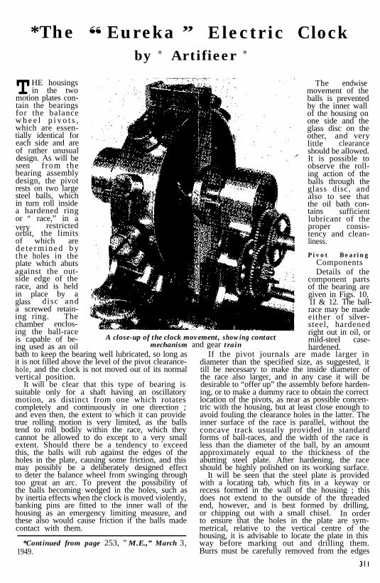
THE housingsin the two
motion plates con-tain the bearingsfor the balancew h e e l p i v o t s ,which are essen-tially identical foreach side and areof rather unusualdesign. As will beseen f rom thebearing assemblydesign, the pivotrests on two largesteel balls, whichin turn roll insidea hardened ringor “ race,” in avery restrictedorbit, the limitsof which arede t e rmined bythe holes in theplate which abutsagainst the out-side edge of therace, and is heldin place by aglass disc anda screwed retain-ing ring. Thechamber enclos-ing the ball-raceis capable of be-ing used as an oilbath to keep the bearing well lubricated, so long asit is not filled above the level of the pivot clearance-hole, and the clock is not moved out of its normalvertical position.
A close-up of the clock movement, showing contactmechanism and gear train
It will be clear that this type of bearing issuitable only for a shaft having an oscillatorymotion, as distinct from one which rotatescompletely and continuously in one direction ;
I and even then, the extent to which it can provide
;true rolling motion is very limited, as the ballstend to roll bodily within the race, which theycannot be allowed to do except to a very small
I extent. Should there be a tendency to exceed
I this, the balls will rub against the edges of the
iholes in the plate, causing some friction, and thismay possibly be a deliberately designed effectto deter the balance wheel from swinging throughtoo great an arc. To prevent the possibility ofthe balls becoming wedged in the holes, such asby inertia effects when the clock is moved violently,banking pins are fitted to the inner wall of thehousing as an emergency limiting measure, andthese also would cause friction if the balls madecontact with them.
*Continued from page 253, ” M.E.,” March 3,1949.
The endwisemovement of theballs is preventedby the inner wallof the housing onone side and theglass disc on theother, and verylittle clearanceshould be allowed.It is possible toobserve the roll-ing action of theballs through theglass disc, andalso to see thatthe oil bath con-tains sufficientlubricant of theproper consis-tency and clean-liness.
Pivot BearingComponentsDetails of the
component partsof the bearing aregiven in Figs. 10,1I & 12. The ball-race may be madeeither of silver-steel, hardenedright out in oil, ormild-steel case-hardened.
If the pivot journals are made larger indiameter than the specified size, as suggested, ittill be necessary to make the inside diameter ofthe race also larger, and in any case it will bedesirable to “offer up” the assembly before harden-ing, or to make a dummy race to obtain the correctlocation of the pivots, as near as possible concen-tric with the housing, but at least close enough toavoid fouling the clearance holes in the latter. Theinner surface of the race is parallel, without theconcave track usually provided in standardforms of ball-races, and the width of the race isless than the diameter of the ball, by an amountapproximately equal to the thickness of theabutting steel plate. After hardening, the raceshould be highly polished on its working surface.
It will be seen that the steel plate is providedwith a locating tab, which fits in a keyway orrecess formed in the wall of the housing ; thisdoes not extend to the outside of the threadedend, however, and is best formed byor chipping out with a small chisel.
drilling,In order
to ensure that the holes in the plate are sym-metrical, relative to the vertical centre of thehousing, it is advisable to locate the plate in thisway before marking out and drilling them.Burrs must be carefully removed from the edges

THE MODEL ENGINEER
of the holes, and they should be polished withthe rest of the surface on both sides of the plate,
-after hardening. As the plate is thin, case-harden-ing is not very satisfactory, and it is better to usethin carbon-steel gauge plate or “ pen steel ”for making it.
There may be some difficulty in cutting orobtaining small glass discs, and the possibilityof using a plastic substitute such as Perspex or
B A N K / N C P I N S
MARCH 17, 1949
type require close end adjustment to worksatisfactorily. Workers who have experiencewith fine horological work may be able to fitjewel bearings and endstones to the pivots insuch a way as to produce little, if any, greaterfriction than a ball-race.
Contact Spring AssemblyThis is shown, together with details of the
BALL-RACE RETAlNlNC RING
cellulose acetate may be considered ;but it should be noted that these discsact as end-locators for the steel balls,and it is therefore desirable to use ashard a material as possible. A usefultip for cutting glass circles is to use achip of tungsten carbide set in aradially adjustable holder like a washercutter or trepanning tool ; it may berun either in the lathe or the drillingmachine.
Should the end clearance of the ballsbe insufficient to allow free movement,a paper washer similar to the one out-side the disc, but having a hole 11/16 in.diameter, may be used between it andthe steel plate. It seems obviouslydesirable to fit a washer in this position,but it was not done in the clockexamined. The screwed retainingrings for the housing may be machined
Left-Fig. I0. Pivot bearing andhousing assembly
/‘/w‘4 Glass Disc Below-Fig. I I. Exploded viewof bearing assembly
TION HOLE OR KEYWAYTAKE TAB ON STEEL P L A T E
in one piece from brass rod, and their,fit in the housings tested before partingoff. They each have two blind holes drilled dia-metrically opposite to each other for the applica-tion of a pin spanner. A trace of varnish on thepaper washers, and on the threads of the rings,will assist in ensuring oil-tightness of the housing.
When the motion plates are fitted to the studsof the armature plate, and the balance wheelassembled in place, the pivots should have justperceptible end shake between the steel platesin the two housings. Adjustment of end playcan be obtained either by fitting shims on thearmature studs or machining back. the shouldersof the studs as required.
Should the construction of this rather elaborateform of pivot bearing be objected to by con-structors, an alternative would be to use thesmallest obtainable standard ball-race, or betterstill, one of the tiny Swiss ball-races speciallymade for instrument work. A cup-and-coneform of bearing like that of a cycle hub, the conebeing formed on the pivot and a carefully machined and hardened cup fitted to the housingin place of the parallel ring, is also a possibility,but it should be noted that ball-bearings of this
312
R E T A I N I N G ’ R I N G
components, in Fig. 13, and it will be seen that thespring is held by means of two 6-B.A. screws,to the vertical edge of a block of ebonite orother insulating material, which in turn is attachedto the back of the front motion plate by a single6-B.A. screw. The contact spring itself is backedup by a check spring of the same material andthickness, to prevent excessive flexure nearthe root of the free end, and a further backing isprovided by a rigid plate of 1/8in. brass strip.Al1 these components are of a simple and straight-forward nature, the only point which calls fordetailed comment being the tipping of the con-tact spring with a small L-shaped piece of silveror gold-silver alloy. Both in obtaining thematerial, and in attaching it to the spring, someconstructors may experience difficulties, but insuch cases it is probable that nearly any workingjeweller would be able to assist in both respects.Silver is quite a satisfactory metal for a contactof this type except for its tendency to tarnish,especially in an atmosphere containing sulphurcompounds, as in industrial towns ; but as thereis wiping contact of the conductors, they are

THE MODEL ENGINEER
B A L L - R A C E
P A P E R W A S H E R G L A S S D I S C RETAININC RING
Fig. 12. Components of pivot bearings (less steel balls)
largely self-cleaning whenkept in continuous use. Thesilver-gold alloy, however,does not tarnish, and beingslightly softer than the silveror german-silver contact pin,acts as a lap to improve itspolish.
The best material for thecontact and check springsis a clock suspension springstrip of approximately thespecified thickness. Thismaterial although finely tem-pered, can be cut quite easilywith sharp shears, and alsofiled ; drilling, however,may present more difficulty,but it may be accomplishedsuccessfully with a glass-hard spear-point drill, madefrom silver-steel and hard-ened right out in water atthe extreme tip ; it should berun fairly slowly and lubri-
4 cated freely with turpentine.It will be noted that thescrew holes in the contactspring are elongated to allowof slight vertical adjustment ;in this detail, some liberty
Y is taken with the originaldesign, as the actual clockexamined had no provisionof this kind, but it appears tobe highly desirable in orderto enable exact adjustmentof the contact timing to beobtained.
A small hole is drilledat the extreme -lower endof the contact spring toassist in soldering the lead
C O N T A C T ’
MARCH 17, 1949
to it, but this is not absolutelyessential, and it may bepreferred to drill and tap thebacking place and fit a smallterminal screw, which wouldavoid the necessity for asoldered connection, andwould be quite satisfactoryfrom the electrical aspectif due care is taken in themetallic contact of the parts.
When the springs aremounted on the block andthe latter attached to themotion plate, it is possibleto adjust the block by pivotalmotion on its single screw,so that the correct actionof the contact gear is ob-tained ; in other words, thatthe contact pin touches thespring on its metallic sideon the clockwise swing, andon the insulated side ofthe return swing. Thisaction should be possible
(Continued on page 331)
A L L O Y T I P
~PNRT,$,~T4 CHkCK
SPRlNC
B A C K / N C P L A T E EBONITE BLOCK
Fig. 13. Details o f contact spring assembly
-7,I
5/s ,
-I

THE MODEL ENGINEER MARCH 17, 1949
S E C T I O N A A
The twin pump for" close quarters ”
[Drawing by Leslie Clarke]
practically explains itself. The valve chambers The two eccentrics are set at 180 deg. or exactlyand waterways are all drilled in a very sub- opposite, so that the flow is practically continuous;stantial cross-stay, which is set back close to the and the method of drilling the waterways, callscoupled axle by removing the inside flanges of for only one feed-pipe and one by-pass. Twothe axlebox on each side. The pump barrels, deliveries are shown for clacks on each side ofwhich have external glands, are made separately, the boiler, but these could be combined intoand attached to the cross-stay by oval flanges,with nuts and studs, as shown in the end view.
a single delivery if the design of the engine calledfor it.
The “ Eureka ” Electric Clock(Continued from page 313)
without the need for setting or bendingthe springs themselves, which is not advisable,though a slight twisting of the contact tip may block.be permissible. Note that very little effortshould be needed to flex the spring to the extentof just over 1/16 in. at the tip, as required to operatethe contact ; the lightest possible action consistentwith just enough contact pressure to conductthe necessary current, will give the best results.
It is now possible to get the balance wheelimpulse motor working, though not to get itproperly rated at this stage. A hairspring ofappropriate length and strength to produce alosing rate should be fitted, and the spring colletadjusted to put the balance “ in beat ” (i.e., withthe core vertical) when at rest. Not more than1-1/2 volts should be used to energise the motor.Adjust the position of the spring so that contactis established at about 15 to 20 deg. to the rightof the dead centre, and broken exactly at dead
centre. This will call for careful and possiblypatient, manipulation of the spring and mounting
When properly adjusted, the action of thebalance wheel should be healthy and vigorous,
_
and the current consumption low, so that only avery minute spark, if any, is perceptible at thecontacts. The motor may be left running whilethe rest of the clock-virtually no more than acounting and indicating gear-is completed.Its movement, however, is so fascinating towatch that it may prove to be a distraction ifset up in the workshop ; it is best to put it insome other part of the house, where it serves the purpose of a decoy for those admiring butoften embarrassing friends who are always“ dropping in ” when some particularly delicatejob is in progress !
(To be continued)
331
*The " Eureka" Electric Clock
by " Artificer "
A READER has pointed out a rather seriousoversight in the details of the balance wheel
which were described in the February 17thissue. It will be noted that the soft iron portionsof this wheel are arranged to form a three-limbedelectro-magnet, the limbs being connected byan iron clamp-piece at the top end, and by abrass clamp-piece at the lower end, so that themagnetic circuit is left open, except for the prox-imity of the armature plate below the wheel.
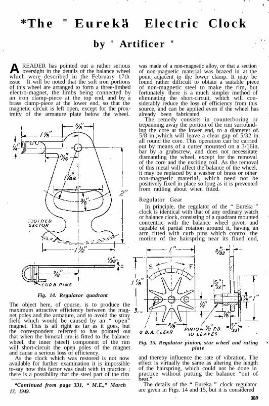
Fig. 14. Regulator quadrant
The object here, of course, is to produce themaximum attractive efficiency between the mag-net poles and the armature, and to avoid the strayfield which would be caused by an “ open”magnet. This is all right as far as it goes, butthe correspondent referred to has pointed outthat when the bimetal rim is fitted to the balancewheel, the inner (steel) component of the rimwill short-circuit the open poles of the magnetand cause a serious loss of efficiency.
Fig. 15. Regulator pinion, star wheel and ratingplate
As the clock which was restored is not nowavailable for further examination it is impossibleto-say how this factor was dealt with in practice ;there is a possibility that the steel part of the rim
and thereby influence the rate of vibration. Theeffect is virtually the same as altering the lengthof the hairspring, which could not be done inpractice without putting the balance “out ofbeat.”
*Continued from page 331, “ M.E.,” March The details of the “ Eureka ” clock regulator17, 1949. are given in Figs. 14 and 15, but it is considered
was made of a non-magnetic alloy, or that a sectionof non-magnetic material was brazed in at thepoint adjacent to the lower clamp. It may befound rather difficult to obtain a suitable piece of non-magnetic steel to make the rim, butfortunately there is a much simpler method ofeliminating the short-circuit, which will con-siderably reduce the loss of efficiency from thissource, and can be applied even if the wheel has already been fabricated.
The remedy consists in counterboring ortrepanning away the portion of the rim surround-ing the core at the lower end, to a diameter of. 5/8 in.,which will leave a clear gap of 5/32 in.all round the core. This operation can be carriedout by means of a cutter mounted on a 3/16in.bar by a grubscrew, and does not necessitatedismantling the wheel, except for the removalof the core and the exciting coil. As the removalof this metal will affect the balance of the wheel,it may be replaced by a washer of brass or othernon-magnetic materia!, which need not bepositively fixed in place so long as it is preventedfrom rattling about when fitted.
Regulator GearIn principle, the regulator of the “ Eureka ”
clock is identical with that of any ordinary watchor balance clock, consisting of a quadrant mountedconcentric with the balance wheel pivot, andcapable of partial rotation around it, having anarm fitted with curb pins which control themotion of the hairspring near its fixed end,

that they are needlessly elaborate, and conferno practical advantage over the simpler form ofregulator as fitted to a cheap alarm clock. Onlyi f it is desired to construct a faithful replica ofthe original clock is it considered worth while tofollow these details exactly. It will be seen thatthe regulator quadrant is equipped with a
Fig. 16. Ratchet lever
toothed segment, engaging a pinion carried in aplate attached to the rear motion-plate of theclock, and fitted with a star wheel on the outside,by means of which it is operated. The quadrantplate has a 1/4 in. pivot hole which fits over thespigot of the rear balance pivot housing, and isretained in place by fitting a washer over it andlightly burring over or expanding the end of thespigot, so that it moves with some friction. Acurved slot is cut in the lower end of the quadrant,which is located by springing it into a slot at theroot of the boss which clamps the end of thehairspring, and this boss also limits the motionof the quadrant, preventing the sector frommoving far enough to get out of mesh with thepinion.
MARCH 31, 1949
wheel may be entirely omitted, also the toothedsector of the quadrant, but the latter should thenhave a second arm extending upwards for opera-ting purposes. A rating plate may be fixed tothe pivot housing to indicate the position of thearm, and show the direction in which it must bemoved to produce a faster or slower rate.
Ratchet LeverAs already mentioned, this component was
entirely absent when the clock was submittedfor restoration, and has been produced from firstprinciples, so there is no guarantee that it isidentical with the one originally fitted. Theform in which it is made is somewhat elaborate,involving the use of three separate parts heldtogether by 14-B.A. screws, and a simpler con-struction, with the parts fabricated by sweatingor riveting would serve just as well, but it shouldbe noted that the construction was experimentaland tentative, and several alterations were calledfor before it produced the desired result, sothat a method of construction which conferredsome measure of mutability was clearly indicated.(Fig. 16.)
The top end of the lever is extended at rightangles to its main length and carries a largediameter disc roller, which is reduced to a narrowrounded edge and polished to reduce frictionwhen in contact with the eccentric on the balancestaff. This may be turned from the solid, as themore orthodox horological method of makingit separate, fixing it to a brass collet, and mountingthe latter on an arbor, confers no practicaladvantage, and entails much more work. Mild-steel, case-hardened on the working surfacesis a suitable material and easier to machine thana carbon steel which could be hardened andtempered. The pivots should be highly polishedand made a little larger than the holes in thelever, which are broached to a working fit ;
The arm extending horizontally from thequadrant is bent U-shaped at the end, and notchesare cut across the span, into which brass curbpins approximately 1/32 in. diameter are sweated. Fig. 17. Roller
Under working conditions, these allow a littleplay for the hairspring, which passes betweenthem, and should touch each of them in turnas it expands and contracts with oscillation of the
this applies also to the other pivot holes for the
balance wheel. By moving the quadrant towardsfeed paw1 and the lever itself. (Fig. 17.)
the anchorage of the spring, its effective freeCase-hardened mild-steel may be used also
length is increased and the clock is slowed down ;for the pawl, similarly turned from the solid,
movement in the other direction has the reversecomplete with its pivots, and filed to the shape
effect and increases the working rate.shown. Before hardening, it should be tried out
If it is decided to simplify the regulator, it isin position to check up on the shape of the point,which should fit the ratchet wheel teeth when
suggested that the pinion, pivot plate and star at the end of its working stroke. The lever pivot
390
u
thofmotprareni nwithPr

THE MODEL ENGlNEER
is a double-ended arbor which is, a press fit in theboss of the front motion-plate, so that the leverstraddles the plate when in position. Note thatthe feed paw1 must be made tail-heavy, so thatit is kept in engagement with the ratchet wheelby gravity. (Fig. 18.)
The backward movement of the ratchet lever,and the depth of “ bite ” of the pawl, are limitedby banking pins fitted to the front motion plate ;in the former case, the pin prevents the rollerfollowing the eccentric right to the bottom of itsstroke, so that under conditions of variablebalance action, the length of stroke of the paw1 isfairly constant, or at any rate, never sufficient toenable it to gather ‘more than one tooth of theratchet wheel. But if, for any reason, excessive
banking pins beforehand, they are-located as closeas possible to their presumed positions andadjusted by bending.
The ratchet wheel is prevented from movingbackwards, on the return swing of the ratchetlever, by a simple backstop spring, which, asalready mentioned, is anchored by a screw to alug cast on the motion plate, below the pivotbearing housing. This spring should be verylight, or it will be noisy in action and also causeunnecessary friction in operating the ratchetwheel. A piece of pendulum suspension spring,bent at the end to the shape shown in Fig. 19,may be used for this purpose, and the hole forthe anchoring screw may, with advantage, beelongated so that the spring can be adjusted to anicety, to drop lightly into engagement with theteeth of the wheel as the ratchet lever comes tothe end of its stroke.
MARCH 31, 1949
but the spacing and numbers of teeth in thewheels and pinions are illustrated in Figs. 19 and20, the latter being in the form of a diagram inwhich it is assumed that the pivots are in linevertically for the sake of clarity.
A rather peculiar, and in some respects in-convenient, feature of this wheel train is that thepitches of the wheels and pinions are not all thesame ; this has no doubt been done in order to
/ xc .-/- ,.\ Ro‘LE*H O U S I N G ’
\ ’I./k---j&
swing of the lever takes place, the second banking CENTRE WHEpin over the paw1 prevents it rising too highso as to gather a second tooth o r jam throughengagement at too steep an angle. As it is very “$~~/tocdifficult to determine the exact positions of the
I imt / IL --+?i 1 1 I
“x--fr-Fig. 18. Feed pawl
Wheel TrainThe method of fitting the train of wheels in
this clock is unusual, and it avoids the necessityof providing a pair of motion plates to accom-modate both ends of the arbor pivots ; but inother respects it is of dubious advantage, andprobably causes more friction than the normalarrangement of wheels on arbors pivoted at bothends. As it is more than probable that any readersinterested in the construction of such a clockwill either utilise an existing wheel train, or havetheir own ideas on its arrangement, it is notproposed to devote much space to its description,
Fig. 19. Arrangement of ratchet gear and mainwheel train
enable the “motion ” wheel and pinion (thatis, the intermediate element of the compoundtrain required to reduce the speed of the hourwheel to 1/12 that of the minute wheel) to run onthe same. arbor as the intermediate wheel ofthe main train. But here again the advantage isquestionable, and it probably would be muchsimpler, particularly for readers who have tocollect suitable gears or cut their own, to avoidthe use of “ mixed ” pitches. ‘The intermediatemotion wheel and its pinion would then have to befitted on a separate fixed stud, as it is in mostnormal types of clocks. Apart from the motionwork, which must obviously provide a 12 to Ireduction, it is not imperative that the reductionratio of the main train should be the same as thatspecified, providing that the number of teeth inthe ratchet wheel is modified to produce thecorrect “ count,” and drive the train at the correctrate for accurate timekeeping.
It may be remarked that some “ Eureka”clocks have been made with the gearing andmotion work disposed differently to that of theexample shown, and in this respect, constructorsmay exercise their own fancy or preference.The example dealt with has an open dial, fittedwith two sockets which push over the spigot extensions of the armature plate studs, and aresecured with grubscrews. The entire movementis mounted, by the lugs of the armature plate,on two vertical pillars, which are in turn boltedto the top of a hollow plinth which houses thebattery-a’ large capacity single dry cell. Adomed glass case is presumably intended to befitted to protect the mechanism from dust,

THE MODEL ENGINEER
though this was missing in the particularspecimen.
Supporting PillarsThese are shown in detail in Fig. 21, and it will
be seen that they are of composite form, and oneof them is devised to form a conduit for thebattery supply lead, so that the latter can bekept invisible, or at least unobtrusive. This is
M/NUTE C A N N O N
O U R C A N N O N
Fig. 20. Diagrammatic side view of wheel train
another optional feature, but many constructorswould consider it simpler to machine the pillarsfrom solid brass-with or without a drilledpassage for the lead. Alternatively, one of thepillars, or its centre bolt, could be insulated andused as a lead-in conductor. The other terminalof the battery is of course “ earthed ” to theframe of the clock, and polarity of the connectionsis of little importance.
In the description of this unique and interestingtype of clock, the writer has attempted to furnishsufficient data to enable the intelligent reader tobuild a clock working on similar principles, ifnot identical in detail. Many thanks are due toseveral helpers in this research, including WingCommander J. Fitzpatrick Lewis, who firstintroduced the particular example to the writer’snotice ; to Mr. F. Hope-Jones, of the Synchro-nome Co., and the staff of the South KensingtonScience Museum, for technical and historicaldata ; and last but not least, to Mr. J. Messageof the “ M,E.” Workshop, for assistance in thepractical work of restoration, and preparation ofnotes and sketches.
Readers’ CommentsDue acknowledgments are made to the many
readers who have written to the writer or theEditor on the subject of the “ Eureka ” or otherunusual types of electric clocks. Some of theletters express an adverse opinion of the clock orcriticism of its design, but in nearly all cases theyshow real interest in the subject, and ask forfurther articles on similar topics.
It is not possible to publish all these letters indetail, or even to quote from them, but one ortwo have been selected by the Editor as con-taining matters of general interest, and will
392
MARCH 31, 1949
appear in the Practical Letters columns of TH EM ODEL E NGINEER in due course. One ratherincoherent correspondent, however, has accusedthe writer of “ cheap sneers ” at the constructorsof Hipp or other simple pendulum clock, thoughsuch a thing was certainly never implied orintended. It is true, as he points out, that suchclocks are easy to build with simple equipment,and perform accurately and reliably; but thisfact, so far from being denied by the writer, wasclearly stated and indeed emphasised in theintroductory article on the “Eureka” clock,together with the motives for bringing the latterto the notice of readers.
Another reader asks “ what ‘is the significanceof the title ‘ Eureka’ applied to this clock?”That is a matter beyond the cognisance of thewriter, and might be answered by anotherquestion-what’s in a name ? But from hazyrecollection of ancient history, the name recallsthe legend of old man Archimedes tearing throughthe streets of Athens in nudist uniform, leaving atrail of soapsuds, and yelling “ I have found it ! ”-on the memorable occasion when he hit uponthe method of finding the specific gravity ofmetals. By inference, one may suppose that theemotions, though probably not the actions, of the
B R A S S T U B E
Fig. 21. Supporting pillars, 2 off (one only drilledand located to form lead conduit)
inventor of this clock were similar-in otherwords, he must have believed that he had really“ got something.” But carrying deduction stillfurther, it is possible that after the disillusionmentcaused by the abortive efforts to exploit thecommercial production of the clock, he may havehad another search through the Greek dictionaryto find the appropriate term for that muchsadder phrase “ I have had it ! ”