the experimental verification of the multi-fuel ic engine
TRANSCRIPT

Vol.:(0123456789)1 3
International Journal of Energy and Environmental Engineering (2021) 12:627–639 https://doi.org/10.1007/s40095-021-00398-w
ORIGINAL RESEARCH
The experimental verification of the multi‑fuel IC engine concept with the use of jet propellant‑8 (JP‑8) and its blends with pure rapeseed oil
Grzegorz Pawlak1 · Patryk Płochocki1 · Przemysław Simiński1 · Tomasz Skrzek2
Received: 3 February 2021 / Accepted: 31 May 2021 / Published online: 11 June 2021 © The Author(s) 2021
AbstractThe paper presents some research results to recognize the possibility of realization of the idea of a multi-fuel IC engine. Future construction is planned as a flexible solution for military or special purpose transport means and emergency power generation. The proposed engine would utilize compression ignition mode for combustion of high reactive fuels (JP-8, diesel oil, etc.) or spark ignition mode for gasoline or other low reactive fuels. Practical implementation of the idea requires that highly reactive fuels be burned efficiently at a low compression ratio suitable for both engine modes. For the test diesel oil, JP-8 and its blends with pure rapeseed oil were chosen as easily accessible fuels. The experiment was carried out on naturally aspirated and supercharged AVL research engine with a common rail system and compression ratio CR = 12. The elaborated, unified injection strategy that synchronized the main dose injection timing with the start of the second stage of homogeneous mixture combustion was checked in practice. The proposed injection strategy applied for CI engine with the low compression ratio enabled efficient combustion and comparable, relatively high engine performance for all tested fuels.
Keywords Multi-fuel IC engine · JP-8 · Pure rapeseed oil · Fuel blends · Low compression ratio · Injection strategy
AbbreviationsATDC After top dead centerBMEP Brake mean effective pressure (bar)BSFC Brake-specific fuel consumptionBTDC Before top dead centerC.A., φ Crank angle (deg)CN Cetane numberCO Carbon monoxideCR Compression ratioDm The main doseDME Dimethyl etherDp1, Dp2, Dp3 Three equal fuel doses making up the
initial doseDO Diesel oil
dp/dφ The rate of cylinder pressure rise (bar/deg)
F-34 A military kerosene type fuel with fuel system icing inhibitor (FSII) also known as JP-8
HCCI Homogeneous charge compression ignition
JP-8 Jet propellant-8LTHR Low temperature heat releaseMFB50 Angular crankshaft position where 50%
of fuel mass burned over an engine cycleNOx Nitrogen oxidesp Cylinder pressure (bar)PM Particle mattersPPC Partially premixed combustionRSO Rapeseed oilTDC Top dead centerTHC Total hydrocarbonsVHRR Volumetric heat release rate (kJ/m3deg)ηth Engine thermal efficiency (-)
* Grzegorz Pawlak [email protected]
1 Military Institute of Automotive and Armor Technology, Okuniewska 1 Street, 05-070 Sulejówek, Poland
2 Faculty of Mechanical Engineering, Kazimierz Pulaski University of Technology and Humanities in Radom, Chrobrego 45 Street, 26-600 Radom, Poland

628 International Journal of Energy and Environmental Engineering (2021) 12:627–639
1 3
Introduction
The paper presents some results of the research aimed at rec-ognizing the possibility of construction of multi-fuel heavy duty engine. Future construction is planned as a flexible solution for military or special purpose transport means and emergency power generation. The proposed engine would utilize compression ignition mode for combustion of diesel oil (DO) or JP-8 and its blends with easily accessible, high reactive fuels or spark ignition mode for gasoline or other low reactive fuels. Practical implementation of this idea requires that highly reactive fuels, such as JP-8 and its blends with pure rapeseed oil, can be burned efficiently at a low compres-sion ratio (CR = 12). The SI engine runs efficiently with a low compression ratio, so the paper does not present results on that. The compression ratio of CI engine is one of the key parameters which, combined with the boost pressure and the injection method, especially injection strategy, determines the conditions in which the fuel is burnt. The experiment combines these parameters to obtain the highest possible and comparable engine performance for fueling with different fuels. The fuels chosen for the experiment are popular, so they could be available under emergency conditions for which future engine use is planned.
Jet Propellant-8 (JP-8) is a military kerosene-type avia-tion turbine fuel. The fuel properties allow JP-8 to be used as a unified NATO fuel (NATO code F-34). It is used for IC engines, especially for heavy-duty CI engines [1]. The sim-ple replacement of diesel oil with JP-8 fuel in conventional CI engine does not mean the same engine performance and emissions because the fuel properties differ significantly from diesel oil. JP-8 consists of C9–C16 hydrocarbons combined with n-paraffins, isoparaffins, naphthenes, and aromatics. A usual aromatics level for JP-8 is 17.3% by volume [2], whereas standard diesel oil contains 4–5%. The typical JP-8 distillation curve starts from 165 °C and finishes at about 267 °C. The lower content of the heavier fractions is the reason for reduc-ing its cetane number (CN = 45). The literature on fueling of CI engine with JP-8 describes experiments conducted on CI engines with typical compression ratio (CR) in the range of 15:1—18:1, equipped with fuel systems designed and opti-mized for diesel oil injection from the point of view of engine performance and its emission [1, 3–6]. Still, there are no many results on the application of JP-8 to naturally aspirated and supercharged CI engine with low compression ratio and adjustment of injection strategy to these specific conditions. The JP-8 properties, such as low viscosity, could be modified by blending the fuel with more dense fuels. The usage of fuel blends changes the mixture creation process and as a conse-quence, influences combustion. The effects of the CI engine fueling with JP-8/diesel oil blends are described in [7]. High cetane number and relatively low emission characteristics are
the most significant advantages of biodiesels. The possible effects of CI engine fueling with such blends were investigated and described in [8–10].
The usage of rapeseed oil (RSO) as an engine fuel can contribute to protecting the climate. Annually around 27.7 million tonnes of rapeseed oil are produced worldwide. The demand for biofuel is set to expand worldwide, especially in the EU. About two-thirds of the total amount of rapeseed oil consumption (annual EU total consumption is about 9.4 million tonnes) is intended for biodiesel. The blends of bio-diesel with fossil diesel have many benefits like reducing emissions, lower engine wear, lesser engine oil consump-tion and comparable thermal efficiency vis-a-vis diesel oil application [11].
Due to the high availability, rapeseed oil is a potential fuel for emergency fueling of power generators or vehicle engines. Pure rapeseed oil as fuel for CI engines was tested and gave some positive results, especially in agriculture. The tests showed that modified tractor engines reliable operation fueled with it is possible and provide some benefits [12, 13]. Rapeseed oil is approximately a C57 compound with one mole having an atomic mass of 890 [14]. Its kinematic viscosity is one of the significant parameters that differ most from diesel oil. At 40 °C, it is about 15 times higher than the kinematic viscosity of diesel oil and 28 times higher than JP-8. Additionally, the viscosity is increasing exponentially with decreasing temperature. The positive effect of the application of rapeseed oil is the reduction in friction when used as an additive to diesel oil [15]. Its lower net calorific value compared to diesel oil is an effect of oxygen in the molecule leading to less combustion air required. Still, the oxygen in the fuel structure can contribute to the improvement of engine emissions. Behind the idea of using rapeseed oil together with JP-8 fuel as a blended fuel is also the blend properties, especially kinematic viscosity higher than JP-8 and much lower than for pure rapeseed oil.
The experiment described in the paper aimed to test the possibility of a combination of low compression ratio with the proposed injection strategy and optionally boost pres-sure to burn all tested fuels (JP-8, JP-8 and pure rape oil blends and diesel oil) in CI engine efficiently and to receive comparable engine performance. In assumption, the drop of cylinder temperature in the compression stroke caused by lowering the compression ratio should be compensated by “cool-flame” oxidation reactions [16]. In this context, the proposed injection strategy is of the utmost importance.
The injection strategy for CI engine with a low compression ratio
The injection strategies for conventional CI engine with typical compression ratio (CR = 15–18) and the influence of injector construction on engine performance, and its

629International Journal of Energy and Environmental Engineering (2021) 12:627–639
1 3
emissions are described in [17–19]. The air/JP-8 mixture formation and its combustion were investigated by the Authors of [7] and [20]. They concluded the application of JP-8 as fuel for CI engine is affected by some charac-teristic phenomena:
1. Liquid-phase penetration of JP-8 is lower than that of diesel oil,
2. Oxidation process of JP-8 is faster than diesel oil, so pre-mixed burn portion in the premixed combustion phase is more significant due to its superior mixing rate through more rapid vaporization characteristics,
3. Superior vaporization characteristics of JP-8 accelerate late-stage combustion,
4. Premixed combustion is predominated (JP-8 could not easily tolerate higher compression ratios because of the dominant premixed combustion phase).
Spray behavior results show that high viscosity fuels have wider spray cone angles, smaller discharge coeffi-cients (the ratio of actual discharge through a nozzle or orifice to the theoretical discharge) and shorter vapor pen-etration than low viscosity fuels [21]. The significant share of high viscosity fuel in a fuel blend (e.g. rapeseed oil) reduces a vapor phase penetration. In turn, the presence of oxygen in its structure should not limit the high oxidation rate of the JP-8 fuel.
The fuel injection strategy should enable the complete combustion of the mixture without excessive heat release, which leads to the engine knock. The choice of a strategy should consider fuel properties, especially the features that influence air/fuel mixture formation. Properties of JP-8 fuel, pure rapeseed oil and diesel oil are presented in Table 1.
There are many concepts of what is called by Rakesh Kumar Maurya in [24] “homogeneous stratification”. He used this term instead of “homogeneous mixture” for homogeneous charge compression ignition (HCCI) diesel combustion. Several publications report the usage of early direct injection to achieve the process for diesel oil. Mix-ture preparation and control strategies in diesel engines are described in [25–27]. Two generations of “Modulated Kinetics” process elaborated by Nissan Motor Company [28], Toyota uniform bulky combustion system (UNI-BUS) [29] and AVL homogeneous charge late injection (HCLI) [30] are the best-known examples of what is called “Premixed Compression Ignition Engine (PCIE)” [31]. In homogeneous charge intelligent multiple injection com-bustion System (HiMICS) described in [32], the pre-mix-ture is formed by a preliminary injection performed during a period from the early stage of the induction stroke to the middle stage of the compression stroke.
Lower octane fuels (such as diesel oil, n-heptane, DME and JP-8) burned in homogeneous charge compression igni-tion (HCCI) processes exhibit a two-stage ignition [24, 33]. The first stage is low temperature heat release (LTHR) or “cool-flame” oxidation reactions (Fig. 1).
The initial dose injection enables controlling the process of combustion and makes low-temperature combustion phase more stable. It can effectively broaden the limits of the start of injection (SOI) of the main dose [34].
The partially premixed combustion (PPC) process for diesel oil relies heavily on the proper mixing between the fuel and the in-cylinder gas. The combustion process is
Table 1 Comparison of JP-8, rapeseed oil and diesel oil properties [11, 13, 22, 23]
Properties Unit JP-8 Rapeseed oil Diesel oil
Low heating value MJ/kg 42.8 37.1 43.2Cetane number – 45 48 50Liquid density at 15 °C kg/m3 804 920 831Kinematic viscosity at
313 Kmm2/s 1.27 35.5 2.35
Carbon kg/kg 0.857 0.774 0.862Hydrogen kg/kg 0.142 0.117 0.135Oxygen kg/kg – 0.109 –Sulfur content mg/kg 150 10 350Flash point °C 57 285 66Distillation:start °C 167 225 17850% °C 202 350 255End °C 238 380 353
-30 -20 -10 0 10 20 30C.A. [deg]
-200
20406080
100120140160
VHRR
[kJ/m3 d
eg]
Fig. 1 Two-stage HCCI combustion process for JP-8—the volu-metric heat release rate (VHRR) for the naturally aspirated (BMEP = 0.3 MPa), and supercharged engine (BMEP = 0.48 MPa), n = 1200 rpm

630 International Journal of Energy and Environmental Engineering (2021) 12:627–639
1 3
dominated by premixed combustion, and the diffusion com-bustion process is quite short at the early single injection mode. It shows the characteristics of both premixed combus-tion and low temperature combustion. However, the ratio of diffusion combustion increases at high load. For the multiple injection strategies, the cylinder pressure and peak pressure rise rate is lower. As the interval between the initial injec-tion and the main injection increases, the mixture is more homogeneous due to sufficient premixing time. However, diffusion combustion plays a dominant role in the double pilot injection mode. The brake-specific fuel consumption (BSFC) and thermal efficiency are considerably improved with pilot injection mode at low load condition, compared with late injection mode. The NOx decreases dramatically in double pilot injection PPC, while the smoke and CO increase, compared with single early injection mode [35]. Optical results described in [36] showed the direct interac-tion of the first and later injection and the interactions of the fuel and the in-cylinder bulk flow fields and surfaces, which could affect mixing and fuel movement hence the efficiency.
The experiment was preceded by the preliminary tests, which showed that the initial dose should be divided into three equal parts and should be injected a minimum of 20 degrees before the main injection (Fig. 2).
The tests also showed that the synchronization of a main dose injection timing with the start of the second stage of homogeneous mixture combustion is an effective way of engine fueling with JP-8 and other examined fuels. Such a synchronization was applied in the experiment (Fig. 3).
The proposed injection strategy divided the combustion process into two phases. The initial dose should enable the appearance of low-temperature heat release (LTHR) and develop the beginning of the second phase of combustion of a quasi-homogeneous mixture. The phase is similar to this observed for typical HCCI (Fig. 1). The main fuel dose injection breaks this phase and starts the partially premixed combustion phase (PPC) (point B in Fig. 3b). The increase in engine load was obtained through the increase in the main dose. The mass of the dose and its injection timing were regulated during the test to receive maximum engine per-formance and avoid an excessive engine knock. The crucial parameter that limited the engine load in the experiment was the rate of cylinder pressure rise (dp/dφ). The limit of dp/dφ was 0.8 MPa/deg for each tested point. Fuel injection pres-sure (FIP) up to 700 bar contributes to superior fuel atomi-zation and improves the PPC process [37]. Further increase in the fuel injection pressure deteriorates the combustion process and engine performance due to intense knocking. The injection pressure (pin = 800 bar) and the nozzle spray angle (162 deg) applied in the experiment contributed to the homogeneity of the lean mixture created by the early injec-tion of the initial dose.
TDC
Dp1 Dp2 Dp3 Dm
Fig. 2 Idea of injection strategy applied in the experiment (Dp1, Dp2, Dp3—three fuel doses making up the initial dose, Dm—the main dose)
-30 -20 -10 0 10 20C.A. [deg]
-200
20406080
100120140160
VHRR
[kJ/
m3 d
eg] VHRR
injection signal
-0.8
-0.4
0
inje
ctio
nsi
gnal
[V]
TDC -30 -20 -10 0C.A. [deg]
-10
0
10
20
VHRR
[kJ/
m3 d
eg] VHRR
injection signal
-0.8
-0.4
0
inje
ctio
nsi
gnal
[V]
A
B
TDC
(b)(a)
Fig. 3 Correlation of fuel injection with the start of the second stage of homogeneous mixture combustion on an illustrative diagram of the volumetric heat release rate (VHRR) (a), the enlargement of the frag-
ment of the diagram with characteristic points: A—the start of injec-tion of the main dose, B—the start of the second stage of homogene-ous mixture combustion (b)

631International Journal of Energy and Environmental Engineering (2021) 12:627–639
1 3
The experiment
The tests were carried out on AVL experimental CI engine with compression ratio 12:1, equipped with a common rail system. The engine parameters are given in Table 2. The engine test equipment was specified in accordance with the Directive of European Parliament and European Council 1999/96 dated 13 December 1999, as well as Regulation (EC) No 715/2007 of the European Parliament and of the Council, dated 20 June 2007 and Commission Regulation (EC) No 692/2008 of 18 July 2008.
The experiment consisted of some load characteristics for JP-8, the blend of JP-8 with 30% of pure rapeseed oil, and JP-8 with 60% of pure rapeseed oil and standard diesel oil. The engine speed was n = 1200 rpm. The speed allowed hav-ing high values of Break Mean Effective Pressure (BMEP) limited by the maximum value of the rate of cylinder pres-sure rise (dp/dφ = 0.8 MPa/deg). For each tested point, cyl-inder pressure diagrams from 100 cycles were registered, and the parameters which describe the combustion process were calculated. Additionally, exhaust gas analysis was car-ried out. The engine base emissions of total hydrocarbons (THC), carbon monoxide (CO), nitric oxides (NOx) and par-ticle matters (PM) were measured with AVL SESAM i60 FT analyzer, which creates an infrared broadband spectrum that is used to detect all spectrum information of the exhaust gas sample at the same time. The absorption spectrum (inten-sity/wavelength) is calculated from the measured interfero-grams (intensity/time) using the Fourier transformation. This absorption spectrum is used to determine the results.
The engine was examined for all tested fuels as a natu-rally aspirated and a supercharged one. The boost pressure applied in the test was pb = 50 kPa.
Results
The experiment was divided into two parts (for the natu-rally aspirated engine and the supercharged engine). For each case, the load characteristics end for different BMEP. The reason is that for the naturally aspirated engine, the maximum BMEP achieved without exceeding the accepted rate of cylinder pressure rise limit (dp/dφ = 0.8 MPa/deg) was much lower than for a supercharged engine. Figure 4 shows the division and injection timing of the fuel dose for all examined engine loads.
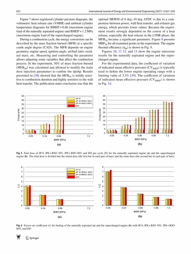
The division, the injection timing of the initial dose (30/25/20 deg BTDC) and the total mass of the initial dose (4 mg/cycle) were the same for all measured points of the engine run. As it turned out, the main dose injection tim-ing modification was necessary for the different engine load because of the limit of the rate of pressure rise. Still, it was not required to modify the injection parameters for each tested fuels. The mass of the main dose for the naturally aspirated engine and the supercharged engine is shown in Fig. 5. Figure 6 presents the excess air coefficient (λ) for all examined points.
Table 2 Engine characteristics
Model AVL 5402Type Direct injection
(common rail)Number of cylinders 1Displacement [cm3] 511Bore/stroke [mm] 85.01/90.00Cycle Four strokeCompression ratio 12:1Maximum power [kW] ca.16Maximum speed [rpm] 4200Inlet valve:Open 346.0 CAClose 586.5 CAExhaust valveOpen 128.5 CAClose 376.5 CANozzle type DLLA 162 P 2160
-40 -35 -30 -25 -20 -15 -10 -5 0 5 -13 -5 TDC
BMEP 0.05 [MPa]
-40 -35 -30 -25 -20 -15 -10 -5 0 5-6 TDC
-40 -35 -30 -25 -20 -15 -10 -5 0 5-8 -5 TDC
BMEP 0.34 [MPa]
BMEP 0.66, 0.96, 1.2 [MPa]
Fig. 4 Injection strategy for different engine loads (BMEP)
632 International Journal of Energy and Environmental Engineering (2021) 12:627–639
1 3
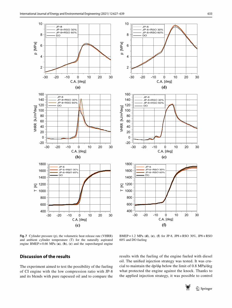
Figure 7 shows registered cylinder pressure diagrams, the volumetric heat release rate (VHRR) and ambient cylinder temperature diagrams for BMEP = 0.66 (maximum engine load of the naturally aspirated engine) and BMEP = 1.2 MPa (maximum engine load of the supercharged engine).
During a combustion cycle, the energy conversion can be described by the mass fraction burned (MFB) at a specific crank angle degree (CAD). The MFB depends on engine geometry, engine speed, ignition angle, air/fuel ratio, resid-ual mass, etc. Measuring and controlling the parameter allows adjusting some variables that affect the combustion process. In the experiment, 50% of mass fraction burned (MFB50) was calculated and allowed to modify the main dose injection parameters to confine the dp/dφ. Results presented in [38] showed that the MFB50 is mildly sensi-tive to combustion duration and highly sensitive to the wall heat transfer. The publication main conclusion was that the
optimal MFB50 of 8 deg–10 deg ATDC is due to a com-promise between power, wall heat transfer, and exhaust gas energy, which prevents lower values. Because the experi-ment results strongly depended on the course of a heat release, especially the heat release in the LTHR phase, the MFB50 became a significant parameter. Figure 8 presents MBF50 for all examined points in the experiment. The engine thermal efficiency (ηth) is shown in Fig. 9.
Figures 10, 11 12, and 13 show the engine emissions results for the naturally aspirated engine and the super-charged engine.
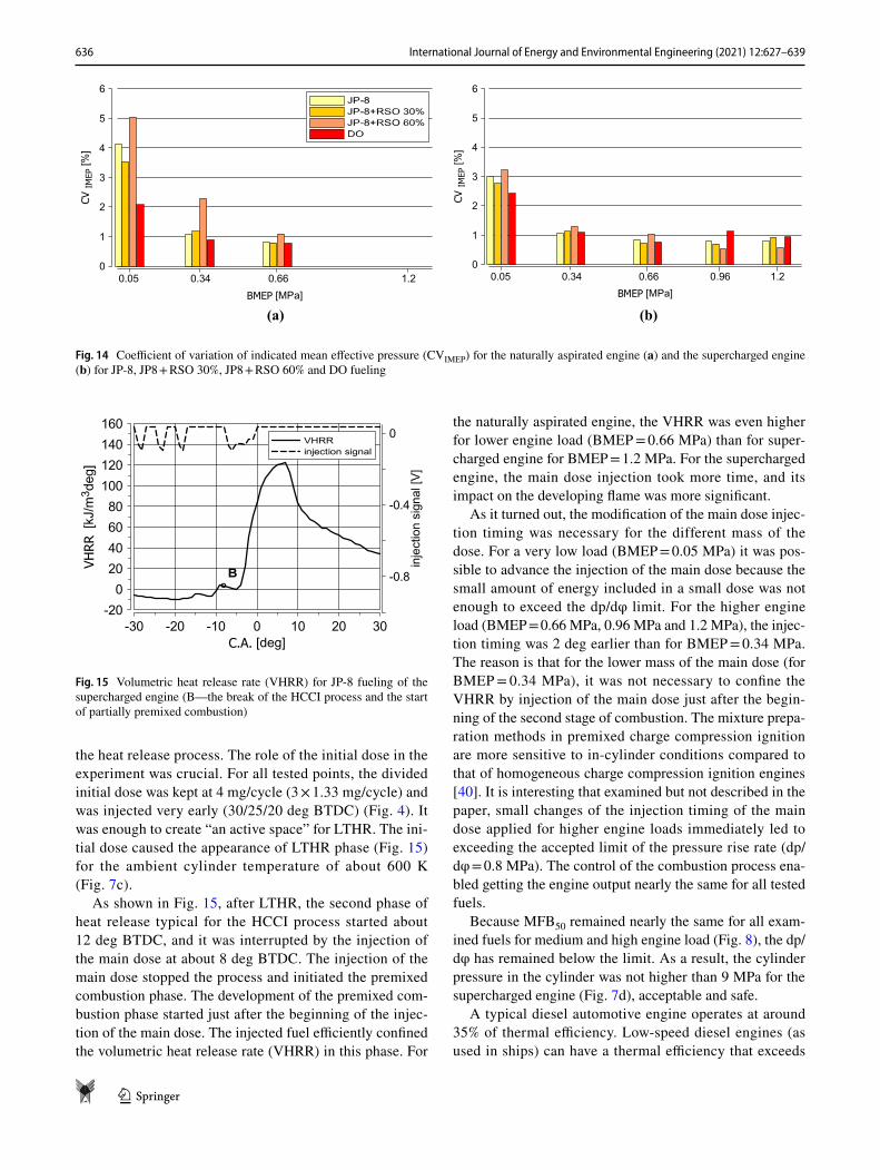
For the experimental data, the coefficient of variation of indicated mean effective pressure (CVIMEP) is typically used to define the lower engine operating range with a limiting value of 3.5% [39]. The coefficient of variation of indicated mean effective pressure (CVIMEP) is shown in Fig. 14.
BMEP [MPa]
0
5
10
15
20
25
30
35
40
45
D[m
g/cycle]
2.166.043.050.0
(a)
BMEP [MPa]
0
5
10
15
20
25
30
35
40
45D[m
g/cycle]
0.05 0.34 0.66 0.96 1.2
(b)
Fig. 5 Fuel dose of JP-8, JP8 + RSO 30%, JP8 + RSO 60% and DO per cycle (D) for the naturally aspirated engine (a) and the supercharged engine (b). The total dose is divided into the initial dose (the first bar in each pair of bars) and the main dose (the second bar in each pair of bars)
BMEP [MPa]
0
1
2
3
4
5
6
7
8
λ [-]
2.166.043.050.0
(a) BMEP [MPa]
0
1
2
3
4
5
6
7
8
λ [-]
0.05 0.34 0.66 0.96 1.2
(b)
Fig. 6 Excess air coefficient (λ) for fueling of the naturally aspirated (a) and the supercharged engine (b) with JP-8, JP8 + RSO 30%, JP8 + RSO 60%, and DO
633International Journal of Energy and Environmental Engineering (2021) 12:627–639
1 3
Discussion of the results
The experiment aimed to test the possibility of the fueling of CI engine with the low compression ratio with JP-8 and its blends with pure rapeseed oil and to compare the
results with the fueling of the engine fueled with diesel oil. The unified injection strategy was tested. It was cru-cial to maintain the dp/dφ below the limit of 0.8 MPa/deg what protected the engine against the knock. Thanks to the applied injection strategy, it was possible to control
-30 -20 -10 0 10 20 30C.A. [deg]
2
4
6
8
10
p[M
Pa]
(a)
-30 -20 -10 0 10 20 30C.A. [deg]
2
4
6
8
10
p[M
Pa]
(d)
-30 -20 -10 0 10 20 30C.A. [deg]
-200
20406080
100120140160
VHRR
[kJ/m
3 deg
]
(b)
-30 -20 -10 0 10 20 30C.A. [deg]
-200
20406080
100120140160
VHRR
[kJ/m
3 deg
]
(e)
-30 -20 -10 0 10 20 30C.A. [deg]
400
600
800
1000
1200
1400
1600
1800
T[K]
(c)
-30 -20 -10 0 10 20 30C.A. [deg]
400
600
800
1000
1200
1400
1600
1800
T[K]
(f)
Fig. 7 Cylinder pressure (p), the volumetric heat release rate (VHRR) and ambient cylinder temperature (T) for the naturally aspirated engine BMEP = 0.66 MPa (a), (b), (c) and the supercharged engine
BMEP = 1.2 MPa (d), (e), (f) for JP-8, JP8 + RSO 30%, JP8 + RSO 60% and DO fueling

634 International Journal of Energy and Environmental Engineering (2021) 12:627–639
1 3
BMEP [MPa]
0
5
10
15
20
25MBF
50[deg
]
2.166.043.050.0
(a) BMEP [MPa]
0
5
10
15
20
25
MBF
50[deg
]
0.05 0.34 0.66 0.96 1.2
(b)
Fig. 8 Angular position of the crankshaft corresponding to the 50% of the fuel mass fraction burned (MBF50) for the naturally aspirated engine (a) and the supercharged engine (b) for JP-8, JP8 + RSO 30%, JP8 + RSO 60%, and DO fueling
BMEP [MPa]
0
10
20
30
40
50
2.166.043.050.0
BMEP [MPa]
0
10
20
30
40
50
0.05 0.34 0.66 0.96 1.2
(b)(a)
Fig. 9 Engine thermal efficiency (ηth) for the naturally aspirated engine (a) and the supercharged engine (b) for JP-8, JP8 + RSO 30%, JP8 + RSO 60%, and DO fueling
BMEP [MPa]
0
200
400
600
800
1000
1200
THC[ppm
]
2.166.043.050.0
BMEP [MPa]
0
200
400
600
800
1000
1200
THC[ppm
]
0.05 0.34 0.66 0.96 1.2
(b)(a)
Fig. 10 Total hydrocarbons emission (THC) for the naturally aspirated engine (a) and the supercharged engine (b) for JP-8, JP8 + RSO 30%, JP8 + RSO 60% and DO fueling

635International Journal of Energy and Environmental Engineering (2021) 12:627–639
1 3
BMEP [MPa]
0
1000
2000
3000
4000
5000
6000CO
[ppm
]
2.166.043.050.0
BMEP [MPa]
0
1000
2000
3000
4000
5000
6000
CO[ppm
]
0.05 0.34 0.66 0.96 1.2
(b)(a)
Fig. 11 CO emission for the naturally aspirated engine (a) and the supercharged engine (b) for JP-8, JP8 + RSO 30%, JP8 + RSO 60% and DO fueling
BMEP [MPa]
0200400600800
1000120014001600180020002200
NOX[ppm
]
2.166.043.050.0BMEP [MPa]
0200400600800
1000120014001600180020002200
NOX[ppm
]
0.05 0.34 0.66 0.96 1.2
(b)(a)
Fig. 12 NOx emission for the naturally aspirated engine (a) and the supercharged engine (b) for JP-8, JP8 + RSO 30%, JP8 + RSO 60% and DO fueling
BMEP [MPa]
0
5
10
15
20
25
30
PM[m
g/m
3 ]
2.166.043.050.0
BMEP [MPa]
0
5
10
15
20
25
30
PM[m
g/m
3 ]
0.05 0.34 0.66 0.96 1.2
(b)(a)
Fig. 13 PM emission for the naturally aspirated engine (a) and the supercharged engine (b) for JP-8, JP8 + RSO 30%, JP8 + RSO 60% and DO fueling
636 International Journal of Energy and Environmental Engineering (2021) 12:627–639
1 3
the heat release process. The role of the initial dose in the experiment was crucial. For all tested points, the divided initial dose was kept at 4 mg/cycle (3 × 1.33 mg/cycle) and was injected very early (30/25/20 deg BTDC) (Fig. 4). It was enough to create “an active space” for LTHR. The ini-tial dose caused the appearance of LTHR phase (Fig. 15) for the ambient cylinder temperature of about 600 K (Fig. 7c).
As shown in Fig. 15, after LTHR, the second phase of heat release typical for the HCCI process started about 12 deg BTDC, and it was interrupted by the injection of the main dose at about 8 deg BTDC. The injection of the main dose stopped the process and initiated the premixed combustion phase. The development of the premixed com-bustion phase started just after the beginning of the injec-tion of the main dose. The injected fuel efficiently confined the volumetric heat release rate (VHRR) in this phase. For
the naturally aspirated engine, the VHRR was even higher for lower engine load (BMEP = 0.66 MPa) than for super-charged engine for BMEP = 1.2 MPa. For the supercharged engine, the main dose injection took more time, and its impact on the developing flame was more significant.
As it turned out, the modification of the main dose injec-tion timing was necessary for the different mass of the dose. For a very low load (BMEP = 0.05 MPa) it was pos-sible to advance the injection of the main dose because the small amount of energy included in a small dose was not enough to exceed the dp/dφ limit. For the higher engine load (BMEP = 0.66 MPa, 0.96 MPa and 1.2 MPa), the injec-tion timing was 2 deg earlier than for BMEP = 0.34 MPa. The reason is that for the lower mass of the main dose (for BMEP = 0.34 MPa), it was not necessary to confine the VHRR by injection of the main dose just after the begin-ning of the second stage of combustion. The mixture prepa-ration methods in premixed charge compression ignition are more sensitive to in-cylinder conditions compared to that of homogeneous charge compression ignition engines [40]. It is interesting that examined but not described in the paper, small changes of the injection timing of the main dose applied for higher engine loads immediately led to exceeding the accepted limit of the pressure rise rate (dp/dφ = 0.8 MPa). The control of the combustion process ena-bled getting the engine output nearly the same for all tested fuels.
Because MFB50 remained nearly the same for all exam-ined fuels for medium and high engine load (Fig. 8), the dp/dφ has remained below the limit. As a result, the cylinder pressure in the cylinder was not higher than 9 MPa for the supercharged engine (Fig. 7d), acceptable and safe.
A typical diesel automotive engine operates at around 35% of thermal efficiency. Low-speed diesel engines (as used in ships) can have a thermal efficiency that exceeds
BMEP [MPa]
0
1
2
3
4
5
6CV
IMEP
[%]
2.166.043.050.0BMEP [MPa]
0
1
2
3
4
5
6
CVIM
EP[%
]
0.05 0.34 0.66 0.96 1.2
(b)(a)
Fig. 14 Coefficient of variation of indicated mean effective pressure (CVIMEP) for the naturally aspirated engine (a) and the supercharged engine (b) for JP-8, JP8 + RSO 30%, JP8 + RSO 60% and DO fueling
-30 -20 -10 0 10 20 30C.A. [deg]
-200
20406080
100120140160
VHRR
[kJ/m3 d
eg]
-0.8
-0.4
0injectionsign
al[V]
Fig. 15 Volumetric heat release rate (VHRR) for JP-8 fueling of the supercharged engine (B—the break of the HCCI process and the start of partially premixed combustion)

637International Journal of Energy and Environmental Engineering (2021) 12:627–639
1 3
50%. For the largest diesel engines, it is about 52%. The engine thermal efficiency ηth obtained in the experiment was around 40% for the naturally aspirated engine and close to 50% for the supercharged engine (Fig. 8). Despite the low compression ratio, the MFB50 observed for higher loads of the supercharged engine were about 13 deg ATDC (Fig. 8). It means that heat losses to walls were confined what con-tributed to relatively high thermal efficiency ηth. Also, the engine speed chosen for the experiment (n = 1200 rpm) con-tributed to high thermal efficiency values. The combustion would take more part of a cycle for higher engine speed, and heat loss to cylinder wall would be higher [41]. The injection strategy applied in the experiment made the com-bustion faster. Even for the low load (BMEP = 0.05 MPa), MFB50 values for all examined fuels was between 15.3 and 17.6 deg ATDC. Additionally, the lower compression work caused by low CR and a high maximum cylinder pressure also contributed to relatively high thermal efficiency values obtained in the experiment. The injection strategy enabled a high VHRR and made it possible to maintain the rate of cylinder pressure rise close to the limit (dp/dφ = 0.8 MPa/deg) and confine the diesel knock.
Total hydrocarbons emission (THC) for diesel oil was slightly lower than for other tested fuels (Fig. 10). Still, par-ticle matter emissions (PM) were lower for the JP-8 and pure rape oil blend with the 60% share of rapeseed oil in the blend (Fig. 13). The low compression ratio contributed to high CO emissions (Fig. 11) and THC for low engine load (BMEP = 0.05 MPa). The boost pressure (pb = 50 kPa) made the excess air coefficient higher (Fig. 6), and the share of CO and THC in the exhaust gases dropped significantly. The leaner mixture contributed to a 30% drop of NOx emis-sion for the supercharged engine for BMPE = 0.66 MPa compared to the emission of the naturally aspirated engine (Fig. 12). The emission raised with the engine loads is nat-ural because of ambient cylinder temperature (Fig. 7). It should be assumed that the fuel combustion mechanism at the front of a flame was similar for all tested fuels because the course of the NOx emission is similar for all tested fuels.
For medium and high engine load cycle by cycle varia-tions of indicated mean effective pressure, CVIMEP remained acceptable (about 1%). The exception is the fueling with a blend of 40% of JP-8 and pure rape oil (60%), especially for the low load (BMEP = 0.05 MPa), where CVIMEP was 5.1% and medium load (BMEP = 0.34 MPa) with a value of CVIMEP = 2.4%. Fuel density is the crucial parameter for the injection process. The results presented in [42] show the influence of the fluid’s density and kinematic viscos-ity on the injection process. The authors concluded that at low rail pressure of 40 MPa, both higher density and higher viscosity could increase momentum thus penetration length; however, at high rail pressure of 120 MPa, density had a pronounced influence while the influence of viscosity was
small [43]. The cone angle of the nozzle (DLLA 162 P2160) used in the test was 162 deg. It was possible that in the case of denser fuel (60% RSO blend with JP-8), some droplets reached the cylinder wall what could be a reason for the local inhomogeneity of the mixture composition and also could contribute to the cycle-by-cycle variation of the combustion process, but it was not confirmed. For the lower BMEP value (0.34 MPa), the naturally aspirated engine showed higher but still acceptable CVIMEP. In this case, CVIMEP is twice higher than for the rest of the examined fuels (Fig. 14).
The experiment described in [33] confirmed that it is possible to realize an LTC process for the JP-8 fuel in a CI engine equipped with a common rail system with low CR (12:1), but the HCCI strategy could be applied only for the limited engine load. The results described in this paper show that the active space creation (the first step of HCCI combustion process) and the synchronization of a main dose injection timing with the start of the second stage of quasi-homogeneous mixture combustion (realization of PPC strategy with carefully chosen injection parameters) can be a method of effective fueling of CI engine with a low com-pression ratio with the use of different fuels.
Summary
The experiment confirmed the possibility of multi-fuel oper-ation of CI engine with low compression ratio with JP-8 as well as its blends with pure rape oil. The proposed injection strategy is an effective way of engine fueling with JP-8 and other examined fuels, including blends of JP-8 with pure rapeseed oil. The strategy which utilized LTHR realized by early injection of divided initial dose and the synchroniza-tion of the main dose injection timing with the start of the second stage combustion of the lean, quasi-homogeneous mixture was efficient and gave the comparable engine per-formance for all tested fuels. Because the test was a part of the investigation on the multi-fuel engine, it was impor-tant to elaborate the same effective injection strategy which could be applied for different fuels. The result showed that for the naturally aspirated engine and supercharged engine, it is possible to use the same fuel injection algorithm with an adjustment of the injection timing of the main dose for the different engine load. It means that the future multi-fuel engine control could be simplified. The realization of the idea demands an application of a multi-fuel injection system and its control as well as an additional spark ignition sys-tem. The development of gasoline high-pressure injection systems gives a perspective of the realization of the idea [44]. The concept does not include construction solutions for its realization. It could still inspire future construction of multi-fuel IC engines as a flexible solution for military or special purpose transport means and emergency generators.

638 International Journal of Energy and Environmental Engineering (2021) 12:627–639
1 3
Declarations
Conflict of interest On behalf of all authors, the corresponding author states that there is no conflict of interest.
Open Access This article is licensed under a Creative Commons Attri-bution 4.0 International License, which permits use, sharing, adapta-tion, distribution and reproduction in any medium or format, as long as you give appropriate credit to the original author(s) and the source, provide a link to the Creative Commons licence, and indicate if changes were made. The images or other third party material in this article are included in the article’s Creative Commons licence, unless indicated otherwise in a credit line to the material. If material is not included in the article’s Creative Commons licence and your intended use is not permitted by statutory regulation or exceeds the permitted use, you will need to obtain permission directly from the copyright holder. To view a copy of this licence, visit http:// creat iveco mmons. org/ licen ses/ by/4. 0/.
References
1. Lee, J., Bae, C.: Application of JP-8 in a heavy duty diesel engine. Fuel 90(5), 1762–1770 (2011)
2. Handbook of aviation fuel properties. CRC Report No. 635, Third Edition (2004)
3. Fernandes, G., Fuschetto, J., Filipi, Z., Assanis, D., McKee, H.: Impact of military JP-8 fuel on heavy duty diesel engine perfor-mance and emissions. Proc. Inst. Mech. Eng. Part D J. Auto. Eng. 221, 957–970 (2007)
4. Sarosh, A., Shahan, M., Javaid, S.: Feasibility assessment of running JP-8 fuel in diesel engine. In: Conference Paper: Inter-national Conference on Aerospace Science and Engineering (ICASE) (2015)
5. Jinwoo, L., Choongsik, B.: Application of JP-8 in a heavy duty diesel engine. Fuel 90, 1762–1770 (2011)
6. Jungyeon, L., Sanghyun, C., Hoimyung, C., Kyoungdoug, M.: Emission reduction potential in a light-duty diesel engine fueled by JP-8. Appl. Energy 89, 92–99 (2015)
7. Labeckas, G., Slavinskas, S.: The effect of aviation fuel JP-8 and diesel fuel blends on engine performance and exhaust emissions. J. KONES Powertrain Trans. 22(2), 129–138 (2015)
8. Uyumaz, A., Solmaz, H., Yilmaz, E., Yamik, H., Polat, S.: Experi-mental examination of the effects of military aviation fuel JP-8 and biodiesel fuel blends on the engine performance, exhaust emissions and combustion in a direct injection engine. Fuel Pro-cess. Technol. 128, 158–165 (2014)
9. Arkoudeas, P., Kalligeros, S., Zannikos, F., Anastopoulos, G., Karonis, D., Korres, D., Lois, E.: Study of using JP-8 aviation fuel and biodiesel in CI engines. Energy Convers. Manag. 44(7), 1013–1025 (2003)
10. Karczewski, M., Szczech, L.: Influence of the F-34 unified bat-tlefield fuel with biocomponents on usable parameters of the IC engine. Maint. Reliab. 18, 358–366 (2016)
11. Tamilselvan, P., Nallusamy, N., Rajkumar, S.: A comprehensive review on performance, combustion and emission characteristics of biodiesel fuelled diesel engines. Renew. Sustain. Energy Rev. 79, 1134–1159 (2017)
12. Emberger, P., Hebecker, D., Pickel, P., Remmele, E., Thuneke, K.: Emission behaviour of vegetable oil fuel compatible tractors fuelled with different pure vegetable oils. Fuel 167, 257–270 (2016)
13. Ettl, J., Bernhardt, H., Huber, G., Thuneke, K., Remmele, E., Emberger, P.: Evaluation of pure rapeseed oil as a renewable fuel for agricultural machinery based on emission characteris-tics and long-term operation behaviour of a fleet of 18 tractors. SN Appl. Sci. 2, 1711 (2020)
14. Mcdonnell, K., Ward, S., Leahy, J.J., McNulty, P.B.: Properties of rapeseed oil for use as a diesel fuel extender. J. Am. Oil. Chem. Soc. 76(5), 539–543 (1999)
15. Szczypinski-Sala, W.: Selected properties of vegetable oil and fuel blends for diesel engine. Mechanics-Cracow University of Technology, Poland (2012)
16. Mehl, M., Pitz, W., Sjöberg, M., Dec, J.: Detailed kinetic mod-eling of low-temperature heat release for PRF fuels in an HCCI engine. SAE Technical Paper 2009–01–1806 (2009)
17. Agarwal, A.K., Som, S., Shukla, PCh., Goyal, H., Longman, D.: In-nozzle flow and spray characteristics for mineral die-sel, Karanja, and Jatropha biodiesels. Appl. Energy 156(15), 138–148 (2015)
18. Kim, H.J., Park, S.H., Lee, C.S.: Impact of fuel spray angles and injection timing on the combustion and emission characteristics of a high-speed diesel engine. Energy 107, 572–579 (2016)
19. Pickett, L., Hoogterp, L.: Fundamental spray and combustion measurements of JP-8 at diesel condition. SAE Int. J. Commer. Veh. 1(1), 108–118 (2009)
20. Jinwoo, L., Heechang, O., Choongsik, B.: Combustion process of JP-8 and fossil diesel fuel in a heavy duty diesel engine using two-color thermometry. Fuel 102, 264–273 (2012)
21. Ochoterena, R., Larsson, M., Andersson, S., Denbratt, I.: Opti-cal studies of spray development and combustion characteriza-tion of oxygenated and Fischer-Tropsch fuels. SAE Technical Paper 2008–01–1393 (2008)
22. www. mach- dynam ics. com/ Techn ical_ Data_ Sheets/ lube/ tds_ JP8. pdf (accessed on 01.12.2020)
23. Bello, E.I., Out, F., Osasona, A.: Cetane number of three veg-etable oils, their biodiesels and blends with diesel fuel. J.Pet. Technol. Altern. Fuels 3, 52–57 (2012)
24. Maurya, R.K.: Characteristics and control of low temperature combustion engines employing gasoline, ethanol and Methanol. Springer, Cham (2018)
25. Mingfa, Y., Zhaolei, Z., Haifeng, L.: Progress and recent trends in homogeneous charge compression ignition (HCCI) engines. Prog. Energy Combust. Sci. 35, 398–437 (2009)
26. Bendu, H., Murugan, S.: Homogeneous charge compression ignition (HCCI) combustion: mixture preparation and control strategies in diesel engines. Renew. Sustain. Energy Rev. 38, 732–746 (2014)
27. Mofijur, M., Hasan, M.M., Mahlia, T.M.I., Ashrafur, R.S.M., Silitonga, A.S., Ong, H.C.: Performance and emission param-eters of homogeneous charge compression ignition (HCCI) engine: a review. MDPI Energies 12(18), 3557 (2019)
28. Kimura, S., Aoki, O., Ogawa, H., Muranaka, S., Enomoto, Y.: New combustion concept for ultra-clean and high-efficiency small DI diesel engines. SAE Technical Paper 1999–01–3681 (1999)
29. Xingcai, L., Dong, H., Zhen, H.: Fuel design and management for the control of advanced compression-ignition combustion modes. Prog. Energy Combust. Sci. 37(6), 741–783 (2011)
30. Jacobs, T., Bohac, S., Assanis, D., Szymkowicz, P.: Lean and rich premixed compression ignition combustion in a light-duty diesel engine. SAE Technical Paper 2005–01–0166 (2005)
31. Jarosinski, J., Veyssiere, B.: Combustion Phenomena: Selected Mechanisms of Flame Formation, Propagation, and Extinction. CRC Press, Taylor & Francis Group (2009)
32. Yokota, H., Kudo, Y., Nakajima, H., Kakegawa, T., Suzuki, T.: A new concept for low emission diesel combustion. SAE Technical Paper 970891 (1997)

639International Journal of Energy and Environmental Engineering (2021) 12:627–639
1 3
33. Pawlak, G., Płochocki, P., Skrzek, T.: Low temperature combus-tion of jet propellant-8 fuel in compression ignition engine with the low compression ratio. Adv. Sci. Technol. Res. J. 14(4), 273–283 (2020)
34. Shi, L., Xiao, W., Li, M., Lou, L., Deng, K.: Research on the effects of injection strategy on LTC combustion based on two-stage fuel injection. Energy 121, 21–31 (2017)
35. Qiu, L., Cheng, X., Liu, B., Dong, S., Bao, Z.: Partially premixed combustion based on different injection strategies in a light-duty diesel engine. Energy 96, 155–165 (2016)
36. Yin, L., Lundgren, M., Wang, Z., Stamatoglou, P., Richter, M., Andersson, Ö., Tunestål, P.: High efficient internal combustion engine using partially premixed combustion with multiple injec-tions. Appl. Energy 233, 516–523 (2019)
37. Jain, A., Singh, A.P., Agarwal, A.K.: Effect of fuel injection parameters on combustion stability and emissions of a mineral diesel fueled partially premixed charge compression ignition (PCCI) engine. Appl. Energy 190, 658–669 (2017)
38. de O. Carvalho. L., de Melo, T., de Azevedo Cruz Neto R.: Inves-tigation on the Fuel and Engine Parameters that Affect the Half Mass Fraction Burned (CA50) Optimum Crank Angle. SAE Tech-nical Paper 2012–36–0498 (2012)
39. Richter, M., Engström, J., Franke, A., Aldén, M., Hultqvist, A., Johansson, B.: The influence of charge inhomogeneity on the HCCI combustion process. SAE Paper 2000–01–2868 (2000)
40. Pachiannan, T., Zhong, W., Rajkumar, S., He, Z., Leng, X., Wang, Q.: A literature review of fuel effects on performance and emis-sion characteristics of low-temperature combustion strategies. Appl. Energy 251, 113380 (2019)
41. Sanli, A., Ozsezen, A.N., Kilicaslan, I., Canakci, M.: The influ-ence of engine speed and load on the heat transfer between gases and in-cylinder walls at fired and motored conditions of an IDI diesel engine. Appl. Therm. Eng. 28(11–12), 1395–1404 (2008)
42. Zink, M., Raatz, T., Wintrich, T., and Eilts, P.: A new approach for characterization of fuel property influence on spray formation in diesel engines, SAE Technical Paper 2010–01–2249, (2010)
43. Zhang, F.: Spray, Combustion and emission characteristics of dieseline fuel, a doctoral thesis, The University of Birmingham, School of Engineering (2013)
44. Piock, W.F., Hoffmann, G., Spakowski, J.G., Dober, G., Gomot, B., Huelser, H.: Delphi technologies next generation GDi system – improved emissions and efficiency with higher pressure, Vienna Motor Symposium 15–17 May (2019)
Publisher’s Note Springer Nature remains neutral with regard to jurisdictional claims in published maps and institutional affiliations.