the field engineer's handbook - university of...
TRANSCRIPT

THE FIELD ENGINEER'S HANDBOOK


T.HE, FIE,Lf)
ENGINEER'S HA}\TDBOOK
A HANDBOOK OF FIELD ENGINEERING FOR
CIVIL ENGINEERS AND ENGINEERING STUDENTS
BY
G. CARVETH WELLS, A.e.G.I. FEDERATED ~IALAY STATES GOVERNMENT RAILWAYS
LATE OF THE GRAND TRUNK PACIFIC RAILWAY, CANADA~
ASSISTANT LECTURER AND INSTRUCTOR IN EXGINEERING SURVEYING
AT THE CITY AND GUILDS (ENGINEERING) COLLEGE,
IMPERIAL COLLEGE OF SCIENCE AND TECHNOLOGY, SOUTH KHNSINGTON
AND
ARUNDEL S. CLAY, B.Sc" A,C.G.I. BRAMWELL MEDALLIST
WITH ILLUSTRATIONS AND TABLES
LONDON
EDWARD ARNOLD


PREFACE
THE authors have written this book because they feel that there is a real need for a handbook on Engineering Surveying. The authors are fully aware that there are many excellent treatises on Surveying, but which, as handbooks for Civil Engineers, are quite unsuitable. Care has been taken with the chapter on the Adjustment of Instruments, as the methods often described are frequently both confusing and unpractical. The chapters on Railway Surveying and Construction will be found useful to those intending to find employment in any of the Colonies. Chapters have been given on the Degree of Curve, which system of surveying curves is becoming more general every day, and upon the Searles Spiral. The latter has not been discussed at great length, though sufficient tables have been given to layout a transition curve. The cubic parabola transition curve has also been discussed. The Astronomy is sufficient to enable a surveyor to find latitude, longitude, and azimuth. It has been written with a view to making the subject as simple as possible, and the reader who knows simple trigonometry should be able to understand it easily; the idea of r Sidereal Time,' which presents great difficulty to the non-mathematical mind, has not been used, or has only been used as a label.
L.~6\'-
\\~O\ ,'j
... -) '--_;:':''-: i ~ J

vi PREFACE
The authors desire to thank their numerous friends who have helped them, and they especially thank W. Hewson, Esq., B.Sc., Assistant Professor in the City and Guilds (Engineering) College, and Colonel A. H. Bagnold, C.B., F.R.A.S., late of the Royal Engineers, for reading the manuscript on Astronomy, and the Astronomer Royal for useful advice on the' Determination of Azimuth.
April, I9I3.
G. CARVETH WELLS,
South Kensington.
ARUNDEL S. CLAY,
St. Michael's Rectory,
Bristol.
CONTENTS
CHAPTER
I. SURVEYIKG INSTRUMENTS, THEIR USE AND
ADJUSTMENT
PAGE
II. CHAIN SURVEYING 30
III. LEVELLING. 35
IV. THE TRAVERSE 42
V. THE SIMPLE CURVE 58
VI. RAILWAY SURVEYING-RECONNAISSANCE AND
PRELIMINARY SURVEY 67
VII. LOCATION 79
VIII. THE RAILWAY TRANSITION CURVE-THE
SEARLES SPIRAL AND THE CUBIC PARABOLA 93
IX. RAILWAY CONSTRUCTION
X. TACHEOMETRY
XI. ASTRONOMy-RELATIVE MOTION OF THE
EARTH, SUN, AND STARS, AND THE DETER-
108
MINATION OF LATITUDE 151
XII. THE DETERMINATION OF AZIMUTH AND TIME 173
XIII. THE POLE STAR . 185
XIV. OTHER METHODS OF FINDING AZIMUTH AND
~TIru~ I~

viii CONTENTS
APPENDICES PAGE
1. THE GENERAL SYSTEM OF LAND SURVEY IN
CANADA 201
II. LATITUDE FORMULAE 209
III. SPHERICAL TRIGONOMETRY 210
TABLES
1. CURVES AND THEIR RADII
II. TANGENT DISTANCES TO A 1° CURVE
III. CORRECTIONS TO TANGENT DISTANCES
IV. MINUTES IN DECIMALS OF A DEGREE
V. ACCELERATIONS OF THE MEAN SUN
INDEX
213
215
223
223
224
225
j
THE FIELD ENGINEER'S HANDBOOK
CHAPTER I
SURVEYING INSTRUMENTS, THEIR USE AND ADJUSTMENT
SURVEYING Instruments fan naturally under three headings:
1. Instruments for making linear measurements. 2. Instruments for measuring vertical heights. 3. Instruments for measuring angles.
Under the first heading come all kinds of chains, steel bands, and linen tapes. Under the second heading come the various types of levelling instruments. While in the third group we have the Transit Theodolite and other instruments for measuring angles.
I. INSTRUMENTS FOR MAKING MEASUREMENTS
The Gunter Chain.-When speaking of a chain, the Gunter chain is always meant. It is a metal
B
2 FIELD ENGINEER'S HANDBOOK
chain 66 feet long, divided into 100 links, each 7'92 inches in length.
This chain is universally used for ordinary Land· Surveying, on account of its convenient length:
I Mile = 80 Chains. I Acre = 10 Square Chains.
In order to make linear measurements, two chainmen are required-the 'Leader' and the , Follower' (often called the Head-chainman and the Rear-chainman).
The leader, taking one end of the chain, and eleven chaining pins, goes forward towards the object to be chained to.
The follower holds his end of the chain at the starting point, and directs the leader so that the chain lies in a straight line between the two points whose distance apart is being measured.
The chain is then pulled tight and the leader puts a pin into the ground to mark the point to which the end of the chain reaches. He then advances, dragging the chain after him.
The follower (who should have let go his end of the chain) comes forward to the pin and holds the end of the chain there.
He again directs the leader, who places another pin at the end of the chain.
When the leader has put in his last (eleventh) pin, the follower gives him the ten pins that he has picked up, and at the same time should note down that 10 chains have been measured.
It must be remembered that all-measurements are supposed to be horizontal, so that,·where the ground slopes or is uneven, the chain.::must be held out hori-

SURVEYING INSTRUMENTS 3
zontally, and a plumb-line used to find the point at which to place the chaining pin.
Hence, in chaining up a hill, the leader must hold his end of the chain on the ground (see Fig. I), but when chaining down hill, it is the follower who must hold his end of the chain on the ground.
If accurate work is required, it is not advisable to employ a Gunter chain, for the following reason:
Each link of the chain is usually joined by three small rings; so that for each link there are eight wearing surfaces. Hence there are 800 wearing
FIG. I
surfaces in a chain of 100 links. If each surface wears only one-hundredth of an inch, the chain would be lengthened by 8 inches. Further comment is needless.
When a chain does get out of adjustment, there is nothing to be done except to send it to the makers for repair, unless the surveyor is satisfied with closing the links here and there.
As a unit of length for Land Surveying, 66 feet cannot be excelled. A 66-foot steel band should 3.lways be used where accuracy is an object to be aimed at.
The Engineer's Steel Tape. - For practically every kind of engineering work, a steel tape, So or 100 feet long and divided into tenths of feet (preferably) or inches, is used, or 66 feet long divided into 100 links.
B2

4 FIELD ENGINEER'S HANDBOOK
The great advantages of steel tapes are: They do not stretch or wear so as to alter their
length appreciably. They do not collect rubbish when dragged along the ground.
Linen Tapes.-These are used for taking measurements where great accuracy is not required, such as in making offsets to a hedge, or roadside.
2. LNSTRUMENTS FOR MEASURING VERTICAL HEIGHTS
The Levelling Statf.-There are so many different types of levelling staffs, and the opinions of their relative values are so varied, that the authors do not propose to describe the detailed appearance of anyone of them. The standard English staff is' the Sopwith telescopic staff, graduated in feet, tenths, and hundredths.
A convenient levelling staff is merely a straight piece of wood, carefully divided into feet, tenths, and sometimes hundredths.
The graduations start from the bottom of the staff and are continued for the whole length of the staff, which may be of any convenient length.
In using a levelling staff, the staff-man holds it in front of him vertically upon the ground, and the leveller sights upon it with the level, and notes the reading covered by the intersection of the cross-hairs.
When readings are being taken upon Bench Marks or Turning Points (see Chapter IV) it is essential that the rod should be h~ld truly vertical.
As this is a difficult thing to do, it is the usual practice to wave the rod backwards and forwards in
SURVEYING INSTRUMENTS 5
the direction of the level through a small angle, taking care to wa ve it on both sides of the vertical.
The leveller reads the least reading, which evidently must occur as the staff passes the vertical.
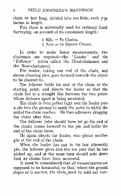
The Dumpy Level!-Consider Fig. 2, which is a diagram only.
r~==~ __ ~~mm==~~ Gr
FIG. 2
The Dumpy Level is an instrument which enables an observer to look in any direction in a horizontal plane. The instrument consists of a telescope, mounted on a tripod. A plate C can be rigidly attached to the top of the tripod. Attached to the plate C by a ball-and-socket joint is a plate A, which can be tilted by means of ' levelling screws' B passing

6 FIELD ENGINEER'S HANDBOOK
through it and bearing on the top of the plate C. In the Level, it is almost universal practice to have four of these levelling screws E.
In the middle of this plate (A) and at right angles to it, is a vertical conical collar D, in which a vertical spindle E is carefully fitted. To this spindle E is rigidly attached the telescope. Attached to the telescope by means of adjustable screws F is a spirit-level.
The Telescope.~Consider Fig. 3.
,S i AF-·_·_·_·_·-ffir FIG. 3
A is the object-glass of the telescope. E is the main tube of the telescope.
o
E is a tube which can be moved in or out or the main tube E, carrying with it the cross-hairs C and the eye-piece F.
The cross-hairs C consist of two or more spiders' webs mounted on a metal ring, which can be moved up or down by the adjusting screws D. (In some dumpy levels, the metal ring or , diaphragm' can have a motion sideways as well, but this is not necessary.) The eye-piece F is capable of a small movement III or out of the tube E.
The object of the cross-hairs is to enable the observer to look along a definite line of sight.
The line joining the intersection of the crosshairs to the centre of the object-glass is called the Line of Sight or Line of Collimation.
SURVEYING INSTRUMENTS 7
TESTS AND ADJUSTMENTS OF THE DUl\IPY LEVEL
Before an instrument can be adjusted it is first necessary to find out what requires adjustment. Hence before using a dumpy level it should be tested as follows:
TEST 1
For Parallax.-Focus the telescope so that the intersection of the cross-hairs covers some welldefined point. Now move the eye from side to side and watch whether the intersection of the cross-hairs remains exactly on the point. If the intersection appears to move with respect to the point on which it was focussed, the instrument needs adjustment.
To Adjust for Parallax.-Hold a piece of white paper in front of the object-glass of the telescope. Look through the telescope and focus the crosshairs by moving the eye-piece in or out until the cross-hairs are very clearly and sharply defined. Now remove the paper, focus the telescope on an object, and repeat the test described above.
TEST 2
The Spirit-level should Revolve in a Truly If orizontal Plane.-Plant the tripod firmly in the ground and turn the telescope so that it is over two opposite levelling screws. Bring the bubble to the middle of its run. Turn the telescope through goa and re-level. Turn the telescope through 1800 , The bubble should remain in the middle of its run. If it does not-
To Adjust the Spirit-level.--Bring the bubble halfway back by means of the adjusting screws on the level tube, and repeat the above test.
8 FIELD ENGINEER'S HANDBOOK
TEST 3
The Line of Collimation should be Parallel to the Spirit-level.-Drive two solid stakes flush with the ground about 200 feet apart. Set up the level midway between the stakes. Take a reading on each stake and note the difference in reading bet ween them.
N ow move the dumpy level and set it up outside both of the pegs, but as near to one of the pegs as will allow the observer to focus on to it. Take a reading on the point next to the instrument, and then on the distant point. If the line of collimation is in adjustment, the difference of the two readings· will be the same as it was before. If a new difference is obtained, then-
To Adjust the Line ofCollimation.-Move the crosshairs up or down until the difference of the readings on the two rods is the same as it was when the instrument was half-way between the points.
Another M ethod.--Choose a level stretch of ground and drive in two stakes as before. Set up midway between them, and drive in one of the pegs until the same reading is obtained on both pegs: that is to say, until the pegs are at the same elevation. Now set up as before near one of the pegs: take a reading on both. If the readings differ, adjust the cross· hairs to make the reading on the far stake agree with that on the near one.
To Set up the Level in the Field.-Assuming the instrument to be in general adjustment, the following operations must be performed every time the level is set up. The vertical axis must be made vertical: hring the telescope over a pair of levelling

SURVEYING INSTRUMENTS 9
screws and the bubble to the middle of its run. Tum through 90°, and again bring the bubble to the middle of its run. The vertical axis is now vertical. In addition to this the adjustment for Parallax must be made by each man using the level, and should always be made at the beginning of a day's work.
The Y-Level.-Consider Fig. 4, which is a diagram only.
F H
M
FIG. 4
. A V-Level consists of a telescope mounted on a tnpod. A plate C can be rigidly attached to the top of the tripod.
Attached to tile plate C by a ball-and-socket joint

10 FIELD ENGINEER'S HANDBOOK
is a plate A, which can be tilted by means of levelling scre'ws B passing through it and bearing on the top of a plate C which is rigidly attached to the top of the tripod.
In the middle of this plate A, and at right angles to it, is a vertical collar D in which a vertical spindle E is carefully fitted.
Rigidly attached to tbe spindle E, and at right angles to it, is a stout metal bar H, carrying at its extremities two Y -supports, one of which is rigidly fixed to the bar, the other being adjustable in height. The telescope rests on these V-supports, and is kept in position by two metal straps J.
Attached to the telescope by means of adjustable screws F and L is a spirit-level G.
The screw F will raise or lower the end of the spirit-level, while the screw L enables the end of the spirit level to be moved sideways. By means of the clamping screw K, rotation on the vertical axis E can be prevented, although a slow motion can be obtained by means of a tangent screw provided (not shown in figure).
TESTS AND ADJUSTMENTS OF THE Y-LEVEL
TEST I
Parallax.-This is exactly the same as described for the dumpy level.
TEST 2
The Line oj Collimation should coincide with the Axis of the Telescope.-Plant the level firmly in the ground and clamp the instrument so that it will not

SURVEYING INSTRUMENTS 11
revolve on its vertical spindle. (There is no necessity to level up the instrument.) Undo the straps of the Y's.
Now bring the intersection of the cross-hairs to cover a well-defined point by means of the levelling screws and the tangent screw on the instrument.
Having done this, twist the telescope itself through 1800 in the Y's, so that the spirit level is on top.
If the intersection does not still coincide with the point, then-
To Adiust the Line of Collimation.-Bring the intersection half-way back to the point, by means of the cross-hair screws.
Carry out this adjustment both for the vertical and horizontal cross-hairs separately. (Note that the telescope of a Y-Ievel, unlike that of most dumpy levels, has four cross-hair adjusting screws.)
TEST 3
The Telescope and the Spirit-level should be parallel. -Level up the instrument over a pair of levelling screws (B, B). Bring the bubble exactly to the middle of its run.
Lift the telescope out of the Y's and gently turn it end for end.
The bubble should return to the middle of its run. If it does not-
To Adiust the Spirit-level.-Bring back the bubble half-way to the middle of its run, by means of the adjusting screw (F) on the level tube.
Now bring the bubble exactly to the middle by means of the levelling screws (B).

12 FIELD ENGINEER'S HANDBOOK
Now twist the telescope slightly, so that the spiritlevel is not exactly underneath the telescope.
If the bubble does not remain in the middle of its run, bring it back to the middle by means of the adjusting screw L.
TEST 4 The Telescope should Revolve in a Horizontal Plane.
-Unclamp the instrument and level up over a pair of levelling screws (B, B).
Turn the whole instrument through 90° (about the vertical axis E). Re-level. Now turn through 180°. The bubble should remain in the middle of its run. If it does not-
To Adjust the Telescope.-Raise or lower the adjustable V-support by means of the screw M until the bubble is brought half-way back to the middle.
Comparison of a Dumpy Level with a V-Level. -The chief advantage of the dumpy level is its simple construction. When once it is adjusted, it should not get out of adjustment if treated carefully: on the other hand, when out of adjustment, two people at least are required to adjust it, and it must be done out of doors on a fairly level stretch of ground.
The V-level, being more complicated in construction, is more liable to get out of adjustment. Its great advantage, however, is that it can be adjusted in a few minutes by one man, either indoors or out of doors or in the middle of a forest.
The Locke Hand LeveI.-This instrument and its use are described in Chapter VII.

SURVEYING INSTRUMENTS I3
3. INSTRUMENTS FOR MEASURING ANGLES
The Transit Theodolite.-A Transit Theodolite, or 'Transit,' consists of a telescofe mounted on a tripod in such a way that horizontal angles and vertical angles can be measured. No other angles can be measured.
Consider Fig. 5, which is a diagram only. Attached to the top of the tripod is a plate C.
A plate A is attached to this plate C by means of three levelling screws (B, B). The plate A can be tilted by means of these levelling screws B, B, which have ball-and-socket joints at one end. At right angles to the plate A is a vertical· conical collar, carrying in it a hollow spindle E to which is rigidly attached the 'lower horizontal plate' F. The circumference of this plate F is graduated in degrees reading from 0° to 360° (in a clockwise direction when viewed from above).
The hollow spindle E acts as a bearing for another spindle G, to which is rigidly attached the 'upper horizontal plate' H. On the edge of this plate is engraved a vernier, which, in the actual instrument, moves in close contact with the lower plate F. (As a rule there are at least two of these verniers on the upper plate.) A hook is attached to the bottom of the spinclle G, and the plumb-line is hung from it.
Rigidly attached to the plate H are two supports or standards J. At the top of these standards are two bearings, one of which is capable of a vertical adjustment by means of the adjusting screw L.
These bearings carry the horizontal spindle or trunnion axis K, to which is rigidly attached the telescope N and vertical circle M. This vertical circle is graduated in degrees.

14 FIELD ENGINEER'S HANDBOOK
Attached to the upper horizontal plate H are two
N
FIG. 5
adjustable spirit-levels (not shown), the longer of
SURVEYING INSTRUMENTS IS
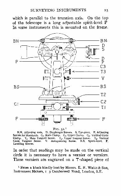
which is parallel to the trunnion axis. On the top of the telescope is a long adjustable spirit-level P In some instruments this is mounted on the frame.
BN --4~::::::::J~--- B.N D S
p----'~
BS-------
D P
J.---"L'------- C.3 +------13
V
-----+--+~----- B.S
..----12
CI ___ ~~~~~~~~--- C2 LJriIOil-"------ T I
F---~=:::=;:::= F
FIG. 5A I B.N. Adjusting nuts. D. Diaphragm Screws. S. Eye-piece. P. Adjusting
Screws for Standards_ Ct. Main Clamp_ C._ Upper Clamp_ c,. Vertical Circle Clamp. Tl' Main Tangent Screw. T2 • Upper Tangent Screw. T3 • Vertical Circle Tangent Screw. V. Antaganising Screw. B.S. Spirit-level. F. Levelling Screws.
In order that readings may be made on the vertical circle it is necessary to have a vernier or verniers. These verniers are engraved on aT-shaped piece of
I From a block kindly lent by Messrs. E. R. Watts & Son, Instrument Makers, I 3 Camberwell Road, London, S.E.

16 FIELD ENGINEER'S HANDBOOK
metal (shown in separate sketch). The trunnion axis passes through this piece of metal at the hole Q, but is not attached to it. The T is kept in position by screwing up the' ant agonising screws' V, V, which clip a piece of metal projecting from the upper horizontal plate (or from the standards). At the same time these screws allow of a certain amount of adjustment of the vernier.
Clamping Screws and Tangent Screws.-The theodolite is capable of three chief motions. Firstly, the whole instrument can rotate bodily relative to the plate A on a vertical axis.
Secondly, the top of the instrument, namely, the upper horizontal plate H (with all its attachments), can be rotated relatively to the lower horizontal plate F on a vertical axis.
Thirdly, the telescope (to which is attached the vertical circle) can be rotated relatively to the vernier plate T on a horizontal axis.
Three clamping screws are provided (not shown in the diagram), one to prevent each of these three movements. In each case a slow-motion or tangent screw is provided so that a slight movement is possible after clamping.
The Telescope.-This is exactly the same as that described for the dumpy level, except that there are (usually) four cross-hair adjusting screws. If there are only two screws they must be at the sides instead of at the top and the bottom as in the dumpy level.
TESTS AND ADJUSTMENTS OF THE TRANSIT
TEST I
Parallax.-Tests and Adjustments just as described for the dumpy level.

SURVEYIKG INSTRUMENTS 17
TEST 2
The Two Small Spirit-levels on the Upper Horizontal Plate should Revolve in a Truly Horizontat Plane.-Bring both the sma1l bubbles to the middle of their run by means of the levelling screws B, B. Turn the instrument bodily through 180°. The bubbles should remain in the middle of their run. If they do not-
To Adjust the Small Spirit-levels.-Confine your attention at present to the long spirit-level on the telescope. Turn the instrument until the telescope is over or parallel to two levelling screws. Bring the bubble to the middle of its run by moving the telescope by hand. Clamp the vertical circle and the upper horizontal plate. Turn the whole instrument through 90°. Bring the bubble to the middle of its run by means of the third levelling screw (or by the two otherlevelling screws in a four-screw instrument). Turn through 180°. If the bubble departs from the middle of its run, bring it half-way back by means of the levelling screw (or screws) and half-way by means of the ant agonising screws. Tum through 1800
again, and, if necessary, bring the bubble back again in the same way. If necessary, do this repeatedly until the bubble remains in the middle of its run when turned through r800. Fina1ly, turn through 90°, and if the bubble departs from the middle of its run bring it all the way back by means of the levelling screws.
The long spirit-level is novY revolving in a truly horizontal plane and consequently the vertical axis is truly vertical, and therefore the upper horizontal plate, being at right angles to the vertical axis, must be truly horizontal. This being the case, bring the
C
18 FIELD ENGINEER'S HANDBOOK
two small bubbles to the middle of their run by means oi their own adjusting screws alone.
TEST 3
The Line of Collimation should be at Right Angles to the Trunnion Axis.-Choose a fairly level piece of ground; set up the instrument and level it carefully. Take a fixed backsight at as good distance away and as near the level of the eye as possible. Clamp the upper and lower horizontal plates. Transit the telescope, and carefully mark the point covered by the intersection of the cross-hairs; this point and the backsight being about the same distance away from the instrument and both on a level with the eye, if possible. Now un clamp the lower plate, and turn the whole instrument round until the cross-hairs again cover the backsight. Re-clamp the lower plate, and again transit the telescope. The intersection should cover the point first marked. If it does not-
To Adjust the Line of Collimation.-By means of the two side cross-hair adjusting screws move the intersection of the cross-hairs over a quarter of the distance from the new point to the point first marked.
Another Method.-If circumstances do not permit of this adjustment, the line of collimation can be adjusted in exactly the same way as described for the V-level, considering the standards to take the place of the V-supports.
TEST 4 The Trunnton Axis should be Parallel to the Upper
Horizontal Plate.-Set up the instrument by the side of some high object such as a church spire, if possible.

SURVEYING INSTRUMENTS 19
Carefully level up, especially the level tube that is parallel to the trunnion axis. Sight the cross-hairs on the high object (the higher the better). Clamp the upper and lower horizontal plates. Depress the telescope and mark a point on the ground covered by the intersection of the cross-hairs (the point being as near to the instrument as possible.) Unclamp the lower plate and turn the whole instrument through 180°. Again sight the high object (this ,vill necessitate transiting the telescope) and depress the telescope. The cross-hairs should again cover the same point. If they do not-
To AdJust the Standal'ds.-Raise or lower one bearing until by repeated test the adjustment is perfected.
TEST 5 The Vernier on the Vertical Circle should read Zero
when the Line of Collimation is Horizontal.-Elevate the telescope and focus upon some fixed point such as the top of a church spire. Read the angle of elevation. Tum the whole instrument round and transit the telescope. Focus on to the same high point and again read the same vernier. The angle of elevation should be the same. If it is not-
. To mde ike Vernier read Zero when Line of Collimation is Horizontal.-Set the telescope so that the vernier reads the mean angle of elevation. This will move the cross-hairs off the object. Bring them back to the object by the ant agonising screws. Repeat the test until the same angle is obtained after transiting the telescope.
When this is the case, the line of collimation will be hoiiz(;mtal wilen the vernier reads zero.
C 2

20 FIELD ENGINEER'S HANDBOOK
If there is a level on the telescope (or on the verniers) the bubble should be in the middle of its. run when the line of collimation is horizontal. Hence, if it is not so, it may be brought to the middle of its run by means of the capstan screws.
After this adjustment has been made it is possible to use the theodolite as a level; but it is riot ad visable to do so.
There is another method of making the line of collimation horizontal without the necessity of sighting on any high object, and is of special use 'when surveying in a flat and open country.
Chose a fairly level piece of ground. Set up the theodolite and level it up very carefully. Drive in two stakes about roo feet on each side of the instrument. Place the telescope as nearly as possible horizontal and clamp the vertical circle. Take readings on two lenlling rods, one placed on each peg. Knock down one peg until the same reading is obtained on both. The pegs will now be level.
Move the theodolite and set up nearly in line with the two pegs so that two readings can be taken simultaneously on the two rods.
N ow set the verniers on the vertical circle to read zero by means of the tangent screw. Elevate or depress the telescope by means of the ant agonising screws until the same reading is obtained on both rods.
The line of collimation is now horizontal, and the bubble on the telescope or vernier may be brought to the centre of its run as before.
Setting up in the Field.-The theodolite is set up for ordinary use just as described for the level, the spirit-level used being the longer one of the two on

SURVEYING INSTRUMENTS 21
the upper horizontal plate. The same note ,,-ith regard to parallax applies.
Levelling Screws.-So far we have assumed that the instrument has been fitted with three levelling screws; this is the best practice in the case of the theodolite. There may, however, be four levellmg screws, in which case the construction of tlce instrument is slightly different, but the principles and the adjustments are the same.
The Compass.-It is very useful, and in fact is customary, to have a magnetic compass permanently attached to the upper horizontal plate. It should be so attached that the North and South graduations are parallel to the telescope.
When the telescope is in its ordinary position, that is to say with the level bubble on top, the object-glass end should be over the North graduation of the compass. If this is so, and the telescope is pointed in any direction, the reading at the North end of the needle is (see Chapter IV) either the nautical or the whole circle bearing depending on the compass graduations. In order for this to be so the East and West graduations of the compass must have been interchanged, and this is always the makers' practice.
Face Right and Face Left.-An instrument is said to be face right when the vertical circle is on the right of the observer when looking through the telescope. It is said to be face left when the vertical circle is on the left of the observer. If the face is changed from right to left and the telescope is again turned to the object, the operation is known as 'Reversing Face.'
Hubs.-The point over which a transit is set up is called a ' hub,' or Instrument Station. A hub should
22 FIELD ENGINEER'S HANDBOOK
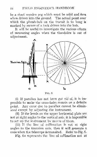
be a stout wooden peg which must be solid and firm when driven into the ground. The actual point over which the plumb-bob on the transit is to hang is marked by means of a tack driven into the hub.
It will be useful to investigate the various effects of measuring angles when the theodolite is out of adjustment.
A
,; ion
Q b FIG. 6
(i) If parallax has not been got rid of, it is impossible to make the cross-hairs remain on a definite point. Any error due to parallax cannot be eliminated except by adjusting the instrument.
(ii) If the levels on the upper horizontal plate are not at right angles to the vertical axis, it is impossible to set up the instrument by means of them.
(iii) If the line of collimation is not at right angles to the trunnion axis, then it will generate a cone when the telescope is transited. Refer to Fig. 6.
Fig. 6a represents the line of collimation not at
SURVEYING INSTRUMENT~ 23
right angles to the trunnion axis. Fig. 6b is the end view of the cone OAB. A section at XX is shown in Fig. 6a and is a hyperbola.
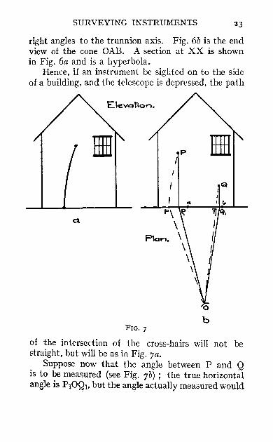
Hence, if an instrument be sighted on to the side of a building, and the telescope is depressed, the path
Cl
b FIG. 7
of the intersection of the cross-hairs will not be straight, but will be as in Fig. 7a.
Suppose now that the angle between P and Q is to be measured (see Fig. 7b); the true horizontal angle is P10Ql. but the angle actually measured would
24· FIELD ENGINEER'S HANDBOOK
be POq, which is not equal to P10Ql' However, if we now' reverse face' and re-measure the angle, the new angle measured will be aOb.
The mean angle will be the true one. Hence, although it is never advisable to use an instrument that i~ out of adjustment, it is seen that the process of reversing face eliminates the error.
In practice, when measuring or setting off angles, or when prolonging a line, two observations should always be made, one face right and the other face left, as it is impossible to keep the line of collimation absolutely in adjustment.
It is especially important to remember this: (a) if working in an east and west direction (as a hot sun warps the telescope tube when continually shining on one side), (b) if working in hilly country.
(iv) If the trunnion axis is not parallel to the upper horizontal plate, it will be evident that the line of collimation will rotate in a plane which is not vertical. Hence, if the instrument be set up as in Figs. 7a and 7b, the curves pp, Qq, will become straight lines. The error, however, is eliminated in exactly the same way by two observations.
(v) If the verniers on the vertical circle do not read zero when the line of collimation is horizontal, it will be evident that the true angle of elevation of an object will not be read.
The instrument-maker sets the two verniers as nearly as possible 180 0 apart, but they are not always exactly so.
Suppose that the transit we are considering has a vertical circle graduated with zero points against each
Q
URVEYING INSTRUMENTS 25
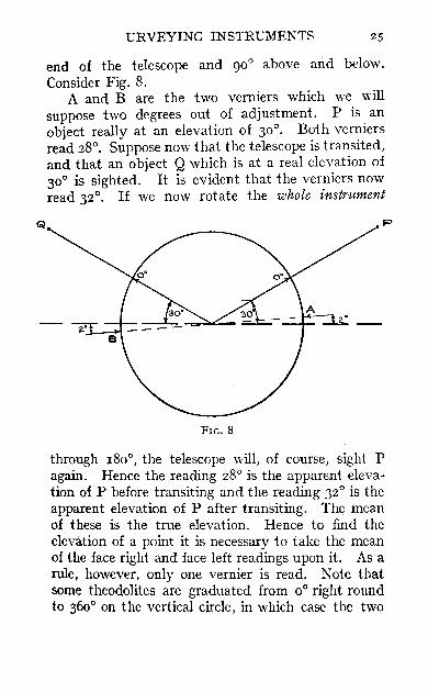
end of the telescope and 90° above and below. Consider Fig. 8.
A and B are the two verniers which we will suppose two degrees out of adjustment. P is an object really at an elevation of 30°. Both verniers read 28°. Suppose now that the telescope is transited, and that an object Q which is at a real elevation of 300 is sighted. It is evident that the verniers now read 32°. If we now rotate the whole instrument
p
FIG. 8
through 180°, the telescope will, of course, sight P again. Hence the reading 28° is the apparent elevation of P before transiting and the reading 32° is the apparent elevation of P after transiting. The mean of these is the true elevation. Hence to find the elevation of a point it is necessary to take the mean of the face right and face left readings upon it. As a rule, however, only one vernier is read. Note that some theodolites are graduated from 0° right round to 360° on the vertical circle, in which case the two

26 FIELD ENGINEER'S HANDBOOK
readings in this case would have been 280 and 20Ro
face left, and I48° and 3280 face right. Therefore, the angles of elevation before and after tram:iting are 28° and 320 and the true angle is 30°. The authors apologise for describing this adjustment in such detail, but they consider that it is very difficult for a beginner to understand it.
The Prismatic Compass.-This is an instrument by means of which the magnetic whole circle bearing of a line can be observed directly. It consists of an ordinary magnetic needle upon which is mounted a cardboard disc, the circumference of which is divided into 360 degrees, starting at the south point and continued in a clockwise direction. The figures are printed as seen in a looking-glass.
A pair of sights are provided. The foresight consists of a fine vertical web and the 'eye' sight consists of a narrow slit above a crystal right-angled prism arranged in such a way that the observer looks through the slit and the prism at the same time. Bv this means he can look at an object and read the graduations at the same time. The graduation covered by the foresight gives the magnetic whole circle bearing. To find the true whole circle bearing see Chapter IV.
Diaphragms.l-In selecting the kind of diaphragm for an instrument the following remarks may be useful:
Web Diaphragms give the cleanest and best lines. They are. of course, very delicate, and must not on any account be touched, but if dust settles on the
I The authors are indebted to Messrs. E. R. \VaJts & Son for the a.bove suggestions.

SURVEYING I~STRUMENTS 27
webs it can usually be removed by blowing gently pn to the diaphragm. In some climates damp affects the webs, and they become sagged or rotten, but, as a rule, webs in ordinary climates will last with care for years.
Glass Diaphragms are very accurate, especially for stadia work, as the width of the spaces is permanent. They are quite safely cleaned by gently rubbing with tissue paper, or, if only dusty, can be cleaned with a soft camel-hair brush. The greatest defect with glass diaphragms is that with changes of temperature moisture is likely to collect on the glass, and so render the telescope useless till it is removed or evaporated.
Point Diaphragms are very good, but if once the points are damaged they are useless. For Levels they are not so suitable, as it is necessary to bring the extreme point of the diaphragm exactly on to the edge of the Levelling Staff before accurate readings can be taken, and this necessitates always having a clamp and slow-motion screw attached to the instrument.
THE CARE AND PROTECTION OF INSTRUMENTS 1
Great care should be taken after using an instrument that all dust and moisture should be wiped off with a soft clean rag or handkerchief. Before placing the instrument in the box note carefully that it is in the correct position, so that the lid will shut without strain. A good plan is to mark the box in such a way as to distinguish clearly in what position
I See note, p. 26.

28 FIELD ENGINEER'S HANDBOOK
the various parts of the instrument are correctly placed, e.g. the eye and object ends of telescope. tangent or slow-motion screws, etc. Before closing the box see that all clamps are tight.
If the instrument is likely to be jolted in transport it is better to lightly wedge some soft rag or woodwool round the principal parts to prevent jarring.
Before using the instrument see that all tangent or slow-motion screws are in the centre of their run, and never force these screws beyond their limit.
Never strain the clamp screws of levelling screws. These should be clamped up tight but not strained.
When levelling with the four-screw adjustment always use an opposite pair of screws together, that is, tighten up one screw with one hand, whilst its opposite screw is loosened with the other hand. By this means the danger of straining the axes is avoided.
It is of no use having an accurate and reliable instrument if the stand on which it is fixed is not rigid; it is as well therefore to examine the head of tripod occasionally to see that it is not loose, as it is quite easy to tighten up the bolts of the head. The shoes also may have worked loose; though this latter very rarely happens.
Be careful when carrying the instrument over the shoulder by the stand to see t.hat the clamps are tight, as if the axes are left loosely swinging, damage to the centres may result. It is, of course, scarcely necessary in this connection to warn surveyors to see that the instrument is securely fixed on the stand.
Unless the compass of an instrument is in actual use, always keep the needle off its pivot by means of the lifter milled head, and also see that this milled

SURVEYING INSTRUMENTS 29
head is screwed right home, so that there is no chance of the lifter working loose, because if the needle swings idly on its pivot the point soon becomes dull, and the needle loses its sensitiveness.
The graduations on the circles should never be rubbed more than is absolutely necessary. If any grit has settled on the graduations, use a small camel-hair brush to dust the circles; a soft rag, moistened with s'weet oil, can be applied carefully to remove tarnish. It is of the utmost importance to keep the divisions sharp, and if they are rubbed very much, the silver, being soft, soon wears.
If tl1e capstan pin is used at any time to correct adjustments, always be careful not to strain the screws or nuts. These should be set tight and no more.
CHAPTER II
CHAIN SURVEYING
Introduction.-To make a survey is to take such measurements in the field as are necessary to prepare a plan, drawn to scale, which will show, as far as possible, all objects within the area included. These measurements may be linear alone, or linear and angular combined.
Plotting a survey is the preparation of the drawings, from the measurements and notes taken by the surveyor in the field.
In Land Surveying, linear measurements are almost universally made in Gunter Chains and Links.
Where works have to be constructed, and quantities calculated in cubic feet and cubic yards, it is more convenient to work with feet entirely.
Therefore, in Engineering surveying, it is usual to lise a Steel Band divided into feet and inches, or, better still, feet and tenths of feet.
For vertical measurements, a Staff divided to feet and tenths is universally used.
There are two kinds of surveying:
(r) Plane Surveying. (2) Geodetic Surveying.
When a survey is of such limited extent that the

CHAIN SURVEYING
earth's curvature may be neglected, it is called a Plane Survey.
When, however, a survey is of a very large area, and great accuracy is required, the effect of the earth's curvature is taken into account, and the survey is then Geodetic.
It will be as well to point out at once that Geodetic Surveying will not be touched upon in this book.
Chain Surveying.-In a chain survey, the measurements taken are entirely linear.
Let it be required to make a chain survey of a small farm. Consider Fig. 9.
Fig. 9 is a sketch of the farm and surrounding field: it is not drawn to scale.
A preliminary examination of the land to be surveyed should first be made, in order to select suitable stations such as 0, B, A, D. Poles would be left at these points.
The surveying party, consisting of two chainmen (leader and follower), two tapemen and the surveyor (who will take all notes and make any sketches that may be necessary), proceed to the starting point 0 of the survey.
The chainmen measure the lengths of all lines, as described in the last chapter, while the tapemen take offsets to the boundary. For instance, it is found that at a point in the line AB, 440 links from A, the t)ffset to the boundary is 6 links to the right; the surveyor makes a note of this in his field book.
Supposing that the lines OA, AB, and BO have been measured, and that sufficient offsets to the boundary have been taken, it is clear that the triangle can ue plotted and the boundary drawn in.
In order that there may be a check on the accuracy

o
GI U Ii 1/ @)
@ t C
~ It
~
6 ~

CHAIN SURVEYING 33
of the chaining, a pole would be left at a point C and its chainage noted, and the length of Be would be measured.
If now it is found that the length of BC, as plotted, agrees with the lengtb as measured in the field, it is evident that the chaining of the lines OA, AB, and BO has been done correctly.
The line BC is called a tie line. By constructing other triangles such as OAD, each
of which must have a tie line, the survey of any piece of land can be made. The general principles of chain surveying only are described in this book. For a detailed description the reader is referred to any treatise on Land Surveying.
Choice of Triangles.-The choice of triangles necessarily depends upon the nature of the ground; but as a general rule it is adyisable to run a long base line, such as OA, across the ground to be surveyed, and on tbis base line to construct large triangles as nearly equilateral as possible (since there may be considerable error in plotting a very obtuse- or acute-angled triangle).
The tie lines themselves should subdivide the large triangles into others as nearly equilateral as possible.
Tie lines are also selected in such positions that render them of the most use in taking offsets.
If there are still objects which are so far from the sides of tbese subsidiary triangles that they cannot be ~asily offsetted, further subdivision of these triangles must be made.
Great care must be taken to keep full, neat and :onsistent field notes, keeping in mind the fact that, Isually, the plotting of the survey is left to a draughtsnan who has no other information but the field book ~o guide him.
D
34 FIELD ENGINEER'S HANDBOOK
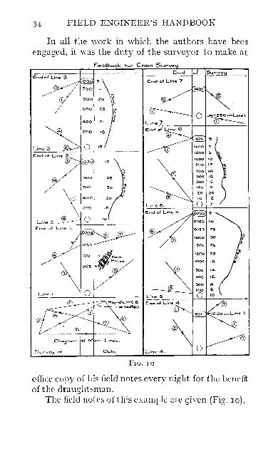
In all the work in which the authors have been engaged, it was the duty of the surveyor to make an
End Surve
J4~1
LinE! :3
1:370
, Line 2 ~E~d;'-' -L,n-.~I-. -+-1------
zoo
30
Line I
Dote, o FIG. 10
office copy of his field notes every night for the hel1cJit of the draughtsman.
The field notes of this e;,.amr1e are giycn (Fig. 10).

CHAPTER III
LEVELLING
THE object of Levelling is to determine the height of ~ertain points above a chosen datum, to whicll are referred all the elevations or levels.
The datum used in the Ordnance Sunoey of England is a certain mark or ( Bench Mark' which ~xists in Liverpool, the height of which above mean ,ea level was once determined.
Scattered all over England are other (Bench \Marks ' cut in milestones, corners of public buildings, I)r other objects of a permanent character. The 11eights of these points have been obtained by levelling :rom the datum bench mark. The position of these )ench marks, together with their elevations, are :learly shown on an ordnance map. These bench narks consist, as a rule, uf a broad arrow pointing
-lpwards with a horizontal bar on the point; the "leight of the bench mark refers to the elevation of the i niddle of the bar. 1 Suppose it is required to find the height of any
Joint. - First consult an ordnance map and find where the
learest bench mark is. Next try and actually find the eeench mark, and having succeeded, set up the level tbout ISO feet away, and carefully level it.
~, D 2

36 FIELD ENGINEER'S HANDBOOK
The Staffman must now hold the bottom of his staff upon the bench mark.
The leveller now looks back, or ' takes a backsighi,' on the staff and takes the reading. This reading, added to the height of the bench mark, gives the height of the Line of Collimation or 'Height of Instrument.'
The Staffman now takes his staff to another point about the same distance on the other side of the instrument and selects a firm object upon which to place the rod.
This point upon which the staff is held is called a Turning Point.
The leveller now looks forward, or 'takes a foresight,' on the staff and takes the reading. This reading, subtracted from the Height of Instrument, gives the elevation or height of the' Turning Point' (so called, because the staff is turned upon it).
The leveller now picks up his level and moves forward beyond the turning point, and again sets it up and levels it carefully.
The process of taking backsights and foresights is now repeated until finally the point of which the elevation is to be found is reached.
The field notes of the levelling operations must be kept methodically in a ' Level Book.'
Below is given the essential features of the most convenient form of level book (Fig. II).
In each line of these notes, the Backsight, Foresight and Elevation all refer to the same point. The order in which these figures were booked is indicat ed by the small letters above the figures. They ha.ve been put in to help the beginner.
If inaccurate readings have been made by the

LEVELLING 37
leyeller, nothing but repeating the work can check its accuracy.
There is, however, a very convenient way of checking the arithmetic of the notes.
The following test must always be made when one page of notes is finished, before beginning a new one.
B.S. H.I. F.S. Elevation.
J' g d 10'91 I II'9-f 5'-f3
h 9'99
S'I2
a 100'00
e 101 '03
i 101 '95
m 95' 1 5
'FIG. II
Remarks.
Bench Mark.
Turning Point.
Turning Point.
Elevation of Point.
Add up the Backsights and add up the Foresights. Subtract one from the other. This figure should be the difference between'the first and last eleyation. For example, in the above notes:
Sum of Foresights 23'54 Sum of Backs'ights 18'69
Difference 4'85
Elevation of first point 100'00 Elevation of last point 95'15
Difference 4'85

38 FIELD ENGINEER'S HANDBOOK
The following practical points must be observe if accurate results are to be expected:
(I) The level must be in as good adjustment Ii possible.
(2) For anyone position ~f the level, the distan .:6 from the level to the staff should be the S2me for bo Ith backsights and foresights.
These distances need not be actually chait led out, but should be estimated by the staffman.
If the line of collimation could be kept in perf ~ct
adjustment, it would not be necessary to take eql l backsights and foresights. ,
(3) The bubble should be brought exactly to t middle of its run when taking a backsight or foresig ,~
(4) Turning points and instrument positio i should be on as firm ground as it is possible to fin,c'l
(5) Sights longer than 300 or 400 feet should ' avoided.
(6) To ensure the true vertical reading bei : obtained, the staff mttst be waved on all turni . points and bench marks (see Chapter I).
In practice, most of the work of levelling consis .; in finding the levels of various 'intermediat I
points in various directions, turning points only bei required for the purpose of finding the height: instrument.
Any intermediate SIght, subtracted from t,~ existing height of instrument, gives the elevation 0.
the intermediate point.' . These intermediate readings are placed in! a
separate column headed 'Intermediate,' and, a~ eu rule, need only be read to the nearest tenth. \'rve
In railway work, in order to obtain a profile alo the centre-line of the raihvay, large numbers le

LEVELLING 39
1termediate points have to be taken, the chainages ( f which are also recorded in a column marked 'Station.' For work of this kind, a conveniEnt f rm of level book is given in Chapter VI.
It may sometimes be com-enient to check a part f some level notes. Below (Fig. 12) is given a page
t ken at random out of a level beok in which a
5"38 17"83 9"43
I
Inter. i I --:
r2'r I
r2'3
r"7
1"4 3"9
r"8 2"4
Elevation.
r8'0
FIG. 12
Remarks.
B.M., Corner of Picture Theatre"
~_l column of intermediate sights is given. Two lines
ave been dra\\'n across it, and it is required to check he arithmetic between them. "
The method of checking about to be described is erely a modification of that for the simple case
iven above. There is no check whatever on intermediate

40 FIELD ENGINEER'S HANDBOOK
readings, but only upon the backsights, foresights, and heights of instrument, these being the readings of vital importance.
For this reason, the lines have been drawn above and below turning points.
Rule.-If there is a foresight on line with the first backsight, cross it out; then the difference between the sum of the backsights and the sum of the foresights should he equal to the differen.~e
between the first Elevation and the last Height of Instrument.
Hence when checking a page of level notes, lightly draw a line above the first and below the last turning point or bench mark.
In this example:
Sum of Backsights Sum of Foresights
Difference
Last Height of Instrument First Elevation
Difference
16'52 8'85
There is another method of booking lewIs, knowr as the Rise and Fall method.
This method involves more calculation than thl Height of Instrument method. It has no correspond ing advantage, except that it enables the arithmeticaJ reduction of the intermediate sights to be checked.
A description of this method is to be found iJ most treatises on Surveying, but it must be dearI>

LEVELLING
understood that the arithmetical chee-k is only available when the rises and falls have been calculated from the last intermediate sight and not from the last backsight.
Precise Levelling.-If very accurate levels are required when levelling is being performed over ground where equal backsights and foresights cannot be taken, it might become necessary to make corrections for the Curvature of the Earth and for Terrestrial Refraction. The Curvature of the Earth makes an object appear too low by an amount of 8 inches in the first mile and varying as the square of the distance (that is in 10 miles it would be 800 inches). Terrestrial Refraction (not to be confused with Astronomical Refraction) makes an object appear too high by an amount equal to about one-seventh of the correction for curvature.
For ordinary work these corrections will not be required.

CHAPTER IV
THE TRAVERSE
Bearings.-Before discussing Traversing it is necessary to explain briefly what is meant by the bearing of a line. Consider Fig. 13.
When the word ., Bearing' is used in this book, the Nautical Bearing (often called Reduced Bearing) is always meant.
The Nautical Bearing of a line is it.s angular distance East or West of the North or South.
Consider the four positions of the line OP :
The Bearing of OP1 is North 60° East. " OP2 " South 45° East. " OPg " South 20° \Vest. " OP .. " North 80° \Vest.
Remember that the angle is always measured either down from the North or up from the South.
Another kind of bearing frequently used is Whole Circle Bearing. In this case, the circle is divided into 360 degrees numbered from zero at the North point, and completely round the circle m a clockwise direction. This bearing is the one read direct off the scale of a prismatic compass,

THE TRAVERSE
Hence-The Whole Circle Bearing of OP1 = 60 0
" OP2 = 1350
" OP3 = 2000
" OPt = 2800
43
y{~------~~~----------~E
5 FIG. 13
It is a matter of simple arithmetic and commonsense to convert Nautical to Whole Circle Bearings, and vice versa. Nevertheless, the reader is advised, when reducing bearings from the whole circle to the nautical system, always to make a sketch like Fig. 13.
Remember that the bearing of a line depends on the direction in which the line is drawn. That is to say, one can walk along the same line in a northeasterly or in a south-westerly direction.
44 FIELD ENGINEER'S HANDBOOK
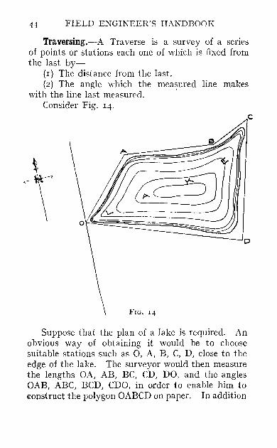
Traversing.-A Traverse is a survey of a series of points or stations each one of which is fixed from the last by-
(r) The distance from the last. (2) The angle which the measured line makes
with the line last measured. . Consider Fig. 14.
FIG. 1{
Suppose tbat the plan of a lake is required. An obvious way of obtaining it would be to choose suitable stations such as 0, A, B, C, D, close to the edge of the lake. The surveyor would then measure the lengths OA, AB, BC, CD, DO, and the angles OAB, ABC, BCD, CDO, in order to enahle him to €onstruct the polygon OABCD on paper. In addition
c

THE TRAVERSE 45
to this, in order to fix the position of the polygon on the plan, he would determine the bearing of the first side ~A.
At the time of measuring the lines or courses, he would take offse~s to the edge of the lake, thereby enabling him to put the outline of the lake on the plan of the polygon. The plotting of such a survey could be done roughly with a scale and protractor.
In practice, if the survey is a small one, it may be convenient to select the stations and place a pole at each, and then to return to the starting point and measure the sides and angles of the existing polygon. But if the survey is a large one it will be better to start from 0 on a certain bearing and stop at a convenient point A. Then to set off some convenient angle OAB and to continue on that bearing until some point B is reached. This point B may easily be several miles from A. This is the usual procedure in surveying the route for a railway.
The essential difference between the two methods of traversing is that in the first case the sides and angles of an existing polygon are measured, but that in the second case the lengths of the sides and the size of the angles are chosen and set out as the traverse proceeds. In both cases the traverse mayor may not be a closed one, that is, it mayor may not return to its starting point. But in the case of a closed traverse in which the sides and angles are being set ottt instead of measured, it will be obvious to the reader that the last angle CDO and side DO must be measured.
\Vhether the traverse is to be an open one or a closed one depends upon the nature of the survey. It is always desirable to close a traverse if it is
46 FIELD ENGINEER'S HANDBOOK
reasonable and possible to do so, because by so doing the accuracy of the work is evidently checked.
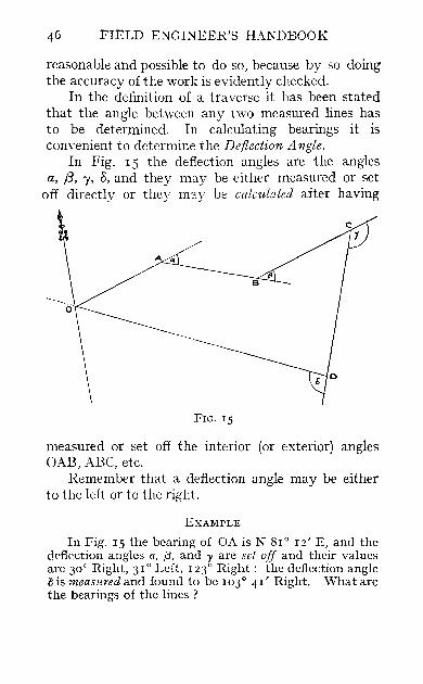
In the definition of a traverse it has been stated that the angle between any two measured lines has to be determined. In calculating bearings it is conyenient to determine the Deflection Angle.
In Fig. 15 the deflection angles are the angles a, /3, "/, 0, and they may be either measured or set
off directly or they m1.y be calculated after having
FIG. 15
measured or set off the interior (or exterior) angles GAB, ABC, etc.
Remember that a deflection angle may be either to the left or to the right.
EXAMPLE
In Fig. IS the bearing of OA is N SI o 12' E, and the deflection angles a, (3, and 'Yare set off and their values are 30° Right, 31° Left, 1230 Right: the deflection angle lJ is measured and found to be 103° 41' Right. What are the bearings of the lines ?

THE TRAVERSE
Bearing of OA = N 81 0 12' E. " AB = S 68° 48' E.
BC= N 80° 12' E. " CD = S 23° 12' vV. " DO = N 53° 07° \V.
EXAMPLE
47
In the last example, the interior angle at 0 was also measured and found to be 45° _p'; that is the deflection angle in going from DO to OA is 134 0 19' H.ight. For the whole circuit add the Right Deflection Anf{les together and add the Left Deflection angles togcther. \Vhat is the difference between these two quantities?
Sum of Right Deflections 3910 Sum of Left Deflections 3 I 0
Difference 360°
Bearing of First Course.-In most cases it is sufficiently accurate to obtain the true bearing of the first course by means of a compass, making allowance for the 1M agnetic Declination. An ordinary compass does not point towards the true north. In some parts of the world it points to tbe east of north, and in other parts to the west of north, and for any gi\'en part of the world it changes from Yf3ar to year. In England at present a compass points about IS ili 0 \\"est of north. This angle is called the Magnetic Declination.
Where the true bearing is required accurately, such as for land or railway surveying, it is necessary to obtain it by Astronomical Observation. This is described later in the book.
Field Work.-The measurement of the lines and the offsets pre5ents no difficulty. TLe only possible difficulty in the field work occurs in the angle5. It has already been stated tbat an angle may be
48 FIELD ENGINEER'S HANDBOOK
measmed (if it exists) and set out (if it does not exist). We will now describe how to measure and how to set out an angle, and also how to prolong a line.
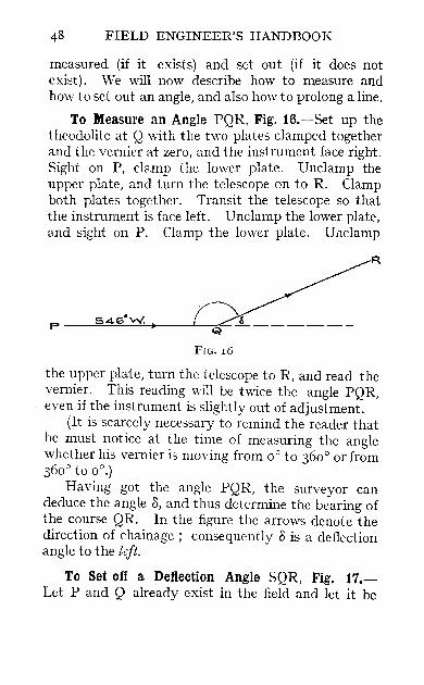
To Measure an Angle PQR, Fig. i6.-Set up the theodolite at Q with the 1\'{0 plates clamped together and the vernier at zero, and the instrument face right. Sight on P, clamp the lower plate. Unclamp the upper plate, and turn the telescope on to R. Clamp both plates together. Transit the telescope so that the instrument is face left. Unclamp the lower plate, and sight on P. Clamp the lower plate. Uaclamp
R
FIG. 16
the upper plate, turn the telescope to R, and read the vernier. This reading will be twice the angle PQR, even if the instrument. is slightly out of adjustment.
(It is scarcely necessary to remind the reader that he must notice at the time of measuring the angle whether his vernier is moving from 00 to 3600 or from 3600 to 0°.)
Having got the angle PQR, the surveyor can deduce the angle D, and thus determine the bearing of the course QR. In the figure the arrows denote the direction of chainage; consequently D is a deflection angle to the lejt.
To Set oft' a Deflection Angle SQR, Fig. 17.Let P and Q already exist in the field and let it be

THE TRAVERSE 49
required to set a hub at R, so that the deflection angle at Q shall be 40°.
Set up at Q, with the instrument face right, and the plates clamped together at zero. Sight on P. Clamp the lower plate. Transit the telescope so that it is now face left. Unclamp the top plate and turn the vernier through 40°. Set a 1mb at R and on it place a tack so that the latter is bisected by the vertical cross-hair. Clamp the two plates together at zero. Unclamp the lower plate and sight on P with the telescope still face left. Clamp the lower plate.
p,------+----...-..:Q~--------~
R
Transit the telescope, so that it is now face right. Unclamp the top plate and turn the vernier through 40°. If the instrument is in perfect adjustment the cross-hair will bisect the tack first set. If it does not, set another tack beside the first and bisected by the new position of the cross-hair. Take another tack and put it midway between the other two tacks. The deflection angle will now be exactly 40°. When setting off an angle this method must be used if errors due to the adjustment of the instrument are to be avoided.
To Prolong a Line PQ to R, Fig. 18.--Suppose that P and Q are stations, and that Q is at the top of a hill, and P on a plain. It may be desirable for the
E

50 FIELD ENGINEER'S HANDBOOK
line PQ to pass right over the hill, but, since it is impossible at P to see farther than Q, the line cannot be prolonged by observation from P. It may, however, be prolonged by observation from Q.
Set up at Q with the instrument face right, and the plates clamped together. Sight on P. Clamp the lower plate. Transit the telescope so that it is now face left. Set a hub at R, and on it place a tack so that the latter is bisected by the vertical cross-hair. Unclamp the lower plate and sight on P with the instrument still face left. Clamp the lower plate. Transit the telescope so that it is now face right.
p
FIG. 18
If the instrument is in perfect adjustment, the crosshair will bisect the tack first set. If it does not, set another tack beside the first and bisected by the vertical cross-hair. Take another tack and place it midway between the other two: this point, R, is now exactly in line with P and Q, even if the instrument is slightly out of adjustment. This process is known as ' Double Centering.'
Enough has been said to ena ble the Surveyor to do the field work for a simple traverse. As regards keeping field notes, no special rules can be laid down, as the notes will depend upon the nature of the work being surveyed. A specimen field book for a special form of traverse is given on page 88.
The field work having been carried out, it would be a simple matter to plot the traverse with scale and protractor, but this is only a rough method. It is usual to plot a traverse by finding the co-ordinate of its stations or angular points. The axes of co-

THE TRAYERSE 51
ordinates are as a rule the' meridian' or North-andSouth line through the starting point, and an Eastand-West line through the starting point.
Consider Fig. 19. 0 is the starting point and XY is anv side of a traverse. XY cos e is caUed the DIFFERENCE OF LATITUDE, or, more commonly,
N
I I. I I"
I~ :LY
~ a _________ J} ~ Dcport""vre.
YV------------------~o~--------------------~
5 FIG. 19
the LATITUDE of the line XV. XY sin e is called the DEPARTURE of the line XV. Notice that e is the Nautical Bearing of XV.
Evidently the co-ordinates of Yare the algebraic sum (or sum taking account of sign) of the departures of the lines between 0 and Y, and the algebraic sum of the latitudes of the lines between 0 and Y.
E 2

52 FIELD ENGIKEER'S HANDBOOK
Latitudes and Departures are termed northings, southings, eastings, or westings, according to their direction.
EXAMPLE
In a traverse OABC, the latitudes and departures of the lines are:
OA. Latitude, 390 feet, Departure, 400 feet, Northing. Easting.
AB. Latitude, 218 feet, Departure, 210 feet, Southing. Easting.
Be. Latitude, 50 feet, Departure, 1021 feet, Northing. Westing.
What are the co-ordinates of C?
Answer.-4II feet West, 222 feet North.
The actual working out of the latitudes and departures is done either by five- or seven-figure logarithms or by a table of latitudes and departures, such as those by Professor Louis.l The latter is much the easier and quicker way.
The computation of the co-ordinates is done systematically by means of a Traverse Table. Fig. 20
shows a Traverse Table for an open traverse.
Checks in a Closed Traverse.-The object of closing a traverse is to find out if the field work and calculations bave been performed accurately. There is a complete check on the measurement of the angles and of the courses.
The angles have been measured correctly if the sum of the deflection angles, reckoning right (let us say) as positive, and left as negative, is 360°.
The courses have been measured correctly if the sum of tbe northings is equal to the sum of the
J 'Traverse Tables,' by Louis & Caunt. (Edward Arnold.) 4s. 6d. net.
THE TRAVERSE 53
southings, and if the sum of the eastings IS equal to the sum of the westings.
The allowable error in these checks depends to a great extent on the size of the traYerse, the number and length of the courses, and the nature of the ground. The chief cause of error in closure is ' Defective Centering' of the theodolite ,vhen measuring the angles, and errors in linear measurements due to not chaining horizontally.
A Trayerse Table for a Closed Tra,"erse is given in Fig. 2I. The checks are shO\m at the bottom of it.
, Correction' of a Closed Traverse. - Suppose to fix our ideas, that there is a square house near the starting point of a traverse. It is conceivable that one side of the house might be set on the plan by offsets from the first course, and that the opposite side might be set on the plan by offsets from the last course. If there were a closing error in the traverse the house might be anything but square when put on the plan.
It is possible to prevent this local distortion by , correcting' the tra ,-ersc. It is cyident to the reader that if the field work has been performed inaccurately, nothing, except repeating the field work, will disclose the error. But it is possible to make the plan a little distorted everywhere instead of greatly distorted near the starting point. This process is not faking, but it is scientific adjustment, and is usually called 'Correcting the Survey.' Ne\-ertheless, the authors consider that its chief value is to obtain an undistorted plan and calculations that are consistent within themseh"es, and that it need not, except in exceptional circumstances, be applied to an Engineering Trayerse. Its chief

TABLE FOR ~ CLOSED TRAVERSE. c..n
I Len~th.L -
Station" of Course
Deflection
Left.
.~.........-
Angles. Bearing.
Right.
.... Co-ordinates.
Latitude" I Departure. Total Total ~ Latitude" Departure" ......
N" I S" 1----; I W" N" tIt
S" E" W" t-' t1 --------
o 752 '0 S 29°25' W
(observed)
_1- ° ° ° ° tIt Z
655"0 1 __ 1369"4 () ...... Z
A
833"5 B
42°06h
~I03I'W
39°52'30"
655"0 369"4 tIt
264"3 1 __ 1790 "5 tIt J;O
91 9"3 1I59"9 en ------
619"25 C
593"5 D 1~026'40"
582 "0
~1471"5 F
N 68°36'30"W
I49°27'300
I N 8005I' E
N I7°24'20" E :
38°07' 4°' N 55°32' E
225"9 576"6 ~ --~ ---- 693"4 I736"5
--586"0 t1 94"4 -- -- tx:l
599"0 II56"5 0 ------ 0 555"4 1 I74"1 __
I 43"6 ~
266"8 .-- 388"71 __ 11
976"4
1 223"21 158n
F~G. 20.

TABLE FOR A CLOSED TRAVERSE.
Co-ordinates.
I Latitude. Departure.
-;- s'-~~I~:~lsl E. IW.I
Iii ° N 86°59' E --11- 6]'9 :1288'3'1' :
(observedl_ __1 ____ i ___ _
I I I 6]'9 1288'3 -N 34°24'-1:.:-129],0 --1==1203'3 == --- -
_3~4'9 1085'0 =1 ~I_-I_-
Bearing.
4GG~
Length Station, 1 of Deflection Angles.
Course. - ---
Left. Right.
1---0 -----
1290 '1
--A I=- _ 121°23'
_I 359'9 B 1 ---1- 37°25'
46]'0 N 3° 01' E
Total I Total La ti tudf'. Departure.
° ° °
c 98° 53' ------ _I' ---__ 1_-__ I_~·3~1_ll 109'6 ~4°08'W 10~J __ 999'5 _ --I f10Cl.4'8 _
1:>1 __ 1_75°36'
I -0-1 732'21 101°31'
I I 728-0 lIO'l
_'. S 8"J'W J. _ 7"'1=1 <086 i._ .. 1
Sums, 397°23' , 37°25' Sums, 83 , '3, 826'8, 13 1 2'9, I3 II '4 397°23' 83 1 '3 13 12 '9
- 37°25' 826'8 I 31 1"4 FIG. 21
Check, 359°58' Error, 4'5, 1'5. Error, 2',
>-l ::r:: trJ
>-l ~ ><: trJ ~ (fJ
trJ
VI (,.'1

56 FIELD ENGINEER'S HANDBOOK
value is for land surveying and balancing preliminary traverses made with instruments of only secondary accuracy, such as the compass,
To • Correct' the Angles.-If th'O deflection angles do not add up to 360°, make them do so by judicious additions or subtractions, As a rule any correction is best applied to the angle adjoining a short course, as it is difficult to bisect with accuracy a pole which is near.
To 'Correct' the N orthings and Southings.Add up the northings and southings, and note the error or difference between them, Correct each northing or southing according to the foHewing rule:
. Correction to a Northing Half Error Northing = Sum of N orthings,
Correction to a Southing _ Half Error ----- Soothing - Sum of Southings,
To 'Correct' the Eastings and Westings.-These are corrected in exactly the same way,
EXAMPLE
In a closed traverse the northings were 310'2, 453'6, and 5':n: the sou things were 4II·O, and 414.8, Find the correction for the first northing,
In this case, sum of Northings sum of Southings
error l{equirccl Correction
3 IO ·2
823'1 825"8
2'7
.~ X 2'7
li23'!
Required Correction 0'5
In this case this correction must be added, as t be l10rthings arc less than the soui.llings,

THE TRAVERSE 57
This is known as the 'Double Axis Method of Correction,' and is used when the angles of the traverse are correct, but the distances haye been inaccurately determined.
If there is reason to belieye that both the angles and the sides of a traverse are inaccurate, such as in a traverse with compass and pacing, another method of ' Correcting' may be employed.
In this method, knovm as 'Buwditch's Method,' the latitudes and departures are corrected, according to the following rule :
~orrection to a Northing Length of the side Total Error in Latitude Perimeter
Similarly for Southings, and for Eastings and Westings.

CHAPTER V
THE SIMPLE CURVE
A SIMPLE curve is the circular arc joining two tangents. There are an infinite number of circles of various
radii which will connect one given straight line with another, but, having selected a curve of definite radius, the points at which the curve touches these two lines are definitely settled. It is the object of this chapter and of Chapter VII to show how these two tangent points are obtained in the field (that is, to show where the surveyor is to leave the straight line and begin a curve), and to show how a circle can be laid out by means of a theodolite and steel band.
The point at which a curve begins is called the Point of Curve (P.C.). The point at which a curve ends is called the Point of Tangent (P.T.). The beginning and end of the curve are distinguished by the direction of the chain age.
In England it is customary to designate a curve by means of its radius: for instance, a Io-chain curve is a curve the radius of which is 10 chains. In most other countries it is customary to designate a curve by means of its 'Degree.' Prominence is given to this method, as it is rapidly becoming the recognised way of surveying curves, being very simple and practical.

THE SIMPLE CURVE 59
The Degree of Curve.-In any curve the angle subtended at the centre by a chord of 100 feet is called the degree of that curve. For instance, if the angle subtended at the centre of a curve by a chord of 100 feet is 4°, the curve is called a ' 4° curve.' It is evident that any curve can be designated either by its radius or by its degree: a certain degree corresponds to a certain radius. For example, we shall see later that a 40 curve has a radius of 1432'7 feet, and that a 15oo-foot radius curve has a degree of 3° 49' 10", As all curves used in railways have very large radii, the radius is of no use in laying out the curve, except for purposes of calculation. As this is the case, it does not matter whether the radius is a round number of feet or a fractional number. On the other hand, the ' degree of curve' is of constant use in laying out the curve, and hence the simpler it is the better. Hence it is usual to choose the degree of curve, and from it calculate the radius, if you require it; but if desired, the radius can be chosen, and the degree calculated from it.
Consider Fig. 22. We know from Euclid that the angle BTC is half the angle TOA, hence if T A is 100 feet long, the angle TOA must be the degree of curve; and the angle BTC (the deflection angle that must be set off at T in order to locate the point A) is half the degree of curve.
It follows then that in practice, if it is required to survey a curve of any degree whatever, the deflection angles that must be used will always be half the degree of curve. This very simple fact entirely obviates the necessity for calculating the deflection angles of a curve.
Unfortunately it is often thought that a loo-foot

60 FIELD ENGINEER'S HANDBOOK
chain mttst be, used in connection with the degree of curve method of running in curves. For the benefit therefore of those engineers who prefer the Gunter chain, it sbould be pointed out that there is no reason whatevet why the degree of curve should not be defined by means of a loo-link chord as well as by a loo-foot chord.
c
T B
FIG. 22
For instance, a 6° curve may be defined as one in which a chord of 100 links subtends an angle at the centre of 6°. The length of chord does not aHect the deflection angles at all; but merely the radius of the curve.
Hence it is.just as easy to run in a curve by the degree method, using a 66-foot chain divided into links, as it is to work with a loa-foot chain divided into feet.
THE SDIPLE CURYE or
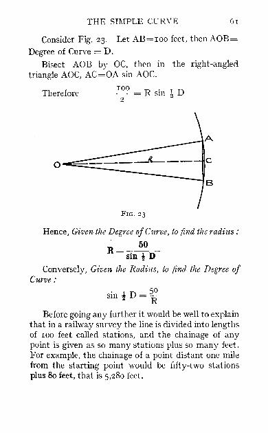
Consider Fig. 23. Let AB=IOO feet, then AOB= Degree of Curve = D.
Bisect AOB by OC, then in the right-angled triangle AOC, AC=OA sin AOe.
Therefore IOO = R sin! D 2 ~
A
c O----__ --l B
FIG. 23
Hence, Given the Degree oj Curve, to find the radius:
R= 50 sin t D
Conversely, Given the Radius, to find the Degree oj Curve:
sin t D = ~o R
Before going any further it would be well to explain that in a railway survey the line is divided into lengths of IOO feet called stations, and the chainage of any point is given as so many stations plus so many feet. For example, the chainage of a point distant one mile from the starting point would be fifty-two stations plus 80 feet, that is 5,280 feet.

62 FIELD ENGINEER'S HANDBOOK
Railway curves are measured by means of a IOo-foot chain stretched between stations, consequently the length of a curve is really the length of an inscribed polygon, and is therefore a little less than the length of the actual curve.
Consider Fig. 2+ Let AB and CD be any two tangents joined by means of a curve. Let A be the total angle subtended by the arc of the curve;
B C I
FIG. 24 it is of course equal to I, the Intersection Angle. If we are given the degree of curve, then it follows from the defmition of degree that the length of the curve will be-
I.e.'-
A 1) X IOO feet
L _ 100 A feet - D
THE SIMPLE CUR V E 63
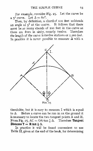
For example, consider Fig. 25. Let the curve be a 5:> curve. Let ~ = 60°.
Then, by definition, a chord of 100 feet subtends an angle of 5° at the centre. It follows that there must be as many chords of 100 feet in the curve as there are fives in sixty, namely twelve. Therefore the length of the curve is twelve stations or 1,200 feet. In practice it is never possible to measure .6. with a
theodolite, but it is easy to measure I which is equal to .6.. Before a curve can be run in on the ground it is necessary to locate the two tangent points A and B. From Fig. 25, AC = OA tan! .6.. Therefore Tangent Distance T = R tan! .6..
In practice it will be found convenient to use Table II, given at the end of the book, for determining

64 FIELD ENGINEER'S HANDBOOK
the Tangent Distance for a circular curve of any degree. The table has been calculated for a rV curve only. For any other degree of curve, it is only necessary to divide the figures given in the table by the degree of curve to be used.
EXAMPLE
Find the Tangent Distance for a 4° that the Intersection Angle I = 45°. From Table II :
Tangent Distance for a 1° Curve = 4° Curve =
Curve. Given
2373'3 593'3
When using this table for curves of 50 or sharper, it is necessary to apply a certain small correction to the figures given.
Table III gives these corrections up to a roo curve for various values of the intersection angle.
If in any case the exact degree of curve or of the intersection angle is not found in the correction table, the value of the correction may easily be obtained from the table by interpolation.
When working with curves sharper that roo, the authors advise that the value of the Radius and Tangent Distance should be calculated, and not taken from any tables. For this reason, the tables given in this book do not go in detail beyond a 100 curve.
Knowing T, the tangent points are determined by chaining from the point of intersection (P.L) of the tangents. Having located the two tangent points, the theodolite can be set up at either and the deflection angles (half the degree of curve) can be turned off and the curve located. The actual running in of a curve will be described in detail later.
It may often be convenient, instead of actually

THE SIMPLE CURVE
running in the curve, to skip from A to B in one process.
Consider Fig. 26. We must first know the length of the long chord C, that is the length of AB.
~~ ______ -,~ ________ /\B
i I /
" I / , I / 'J;
o FIG. 26
In the right-angled triangle OAG
AG = AO sin AOG Therefore Therefore
!C=Rsin!A C=2Rsin!A
Hence if we set up the theodolite at A and turn off the angle lAB = ! A, then, knowing the length of the long chord, we can chain from A and locate the point B.
F
66 FIELD ENGINEER'S HANDBOOK
To summarise: in any curve we have-
100..:l The Degree of Curve D = -L-
100..:l The Length of Curve L = u-
The Radius R = . 5~ D sm "2
The Tangent Distance T = R tan l..:l The Long Chord C = zR sin l ..:l
The Central Angle ..:l = I
The Intersection Angle I = External angle between tangents.
For a detailed description of the use to which these results are put, when actually laying out a circular curve in the field, the reader is referred to the chapter on ' Railway Location.'
CHAPTER VI
RECONNAISSANCE AND THE PRELIMINARY SURVEY
BEFORE a railway can be constructed there are three distinct operations that must be performed:
1. The Reconnaissance. 2. The Preliminary Survey. 3. The Final Surveyor Location.
The present chapter is devoted to the first two of these. The purpose of the Reconnaissance is merely to get a general idea of the topography of the country through which it is proposed to survey the line, and finally to select the most favourable ground in the vicinity.
The fact of it being a survey of an area and not of any particular line must be well borne in mind.
The work is usually carried out by one of the most experienced engineers, and is more of the nature of an exploration than a survey.
The first step is to obtain the best available maps of the district, on which can be sketched the several possible routes for the proposed railway.
Reports are made to headquarters showing the main features of the region traversed by each line; details being given as to the probable gradients that
F 2

68 FIELD ENGINEER'S HANDBOOK
each line would require, and whether such a line is likely to be fairly direct or very circuitous.
It is not always the most direct line that is the cheapest, and it is here that the engineer's skill must be shown.
The theodolite and level are not used on Reconnaissance; but in the place of them are used the prismatic compass and aneroid. (Many engineers prefer the miner's dial to the prismatic compass. The former consists of a compass, fitted with sights and mounted on a tripod.)
The bearing of all trial lines is determined by means of the prismatic compass, while the difference of elevation of different places is determined with the aneroid.
Various methods are employed for determining the distances covered. Ordinary pacing is scmetimes practised, but frequently some kind of perambulator is used. An ordinary iron wheel fitted with a cyclometer is a common type of perambulator. Great care is taken to note on the map the governing points of any route, such as the best place for crossing a river or a valley.
The engineer should keep a diary in which should be entered every evening a record of the day's work. This diary should contain everything of value noted during the day, and it should be turned in to headquarters when the survey is completed.
Only engineers with great experience are placed on Reconnaissance work, but it is well for the reader to have an idea of the work leading up to the Preliminary Survey.

THE PRELIMINARY SURVEY 69
THE PRELIMINARY SURVEY
INTRODUCTION
The methods employed on Preliminary Surveys are very varied in different parts of the world. Local conditions and the fancy and experience of the engineer in charge of the work generally determine which of the numerous systems shall be adopted.
In a paper on 'West African Government Railways,' read before the Institution of Civil Engineers in 1912, by Mr. Frederick Shelford, M.LC.E., a great deal of interesting information was given concerning the conduct of preliminary surveys in West Africa.
In some of these surveys, distances were measured by pacing and direction judged by shouting! Between such a method and an accurate theodolite
. and spirit-level survey there are many gradations. The general principle, however, is the same in all
cases, namely to obtain, by running a traverse and by levelling, a base line from which, by approximation, a railway line may be located.
In countries where the surveyor is entirely dependent upon native labour it is essential that some method of surveying should be employed that will give good results in spite of the labour being unskilled. For instance, in Africa, India, and South America, where survey parties are frequently composed of a number of natives in charge of a skilled engineer, the system of surveying known as Tacheometry is in great favour. See Chapter X.
Under the conditions mentioned, and where speed is of more importance than accuracy, and where the country is open and free from forests, jungle, or other obstructions, there is no doubt that

70 FIELD ENGINEER'S HANDBOOK
the Tacheometer provides a very rapid and con venient method of carrying out preliminary surveys.
The methods of surveying with the Tacheometer are endless, and each way is always considered, by the person employing it, to be the best and only way.
For this reason, the authors have decided that it would be more useful to the majority of their readers to give a separate chapter on the General Theory of Tacbeometry, rather than describe in great detail any particular system.
\Vhen once the principles of tacheometry have been thoroughly grasped, there should be no difficulty in understanding any particular system of performing the practical operations which the reader may encounter.
It cannot be disputed that for Preliminary Survey work there is no method that can compare in accuracy \\ ith the ordinary method of surveying with the Theodolite, Level, and Steel Band.
This method, therefore, has been taken as a standard to be worked to, and one always to be employed where time, money and local conditions will permit.
THE PRELIMINARY SURVEY WITH THEODOLITE
AND LEVEL
HaYing decided from the Reconnaissance which route is likely to be the most suitable, a Preliminary Survey is made of the line, the purpose of vvhich is to serve as a base for the topography. This survey consists of a thorough examination of the land along the proposed line by means of theodolite and level.
THE PRELIMINARY SURVEY 71
The topography of the land in the immediate vicinity of the route is taken accurately. Such a survey necessitates the organisation of a Survey Party. The main party, in charge of the Locating Engineer, is generally divided into three sections:
(r) The Theodolite Party. (2) The Level Party. (3) The Topographer's Party.
The locating engineer directs the survey. He has been previously supplied with the maximum allowable grade and the sharpest curve that he is to use. He must, therefore, choose his path accordingly. He often takes with him an assistant, carrying a picket, which is planted at some point, selected by the chief, ahead of the survey party, and towards this point the chainers proceed. The Theodolite Party consists of-
Instrumentman. Head Chainman or ' Leader.' Rear Chainman or' Follower.' Stakeman. Back Flagman. Axemen.
The Axemen clear the line of sight for the theodolite. They should be expert with an axe, since on them depends greatly the rate of progress of the whole party. The actual starting point of the survey is made by driving into the ground a ' hub' or stout wooden peg, driven flush into the earth; this point being given the stationage 0 + 00.
A tack is driven into the wood, and the theodolite is set up immediately over the tack.

72 FIELD ENGINEER'S HANDBOOK
The Instrumentman then directs the chaining party along the first course, the direction of which is chosen by the locating engineer, and the bearing of which is determined astronomically or from a known bearing. The instrument man is usually chief of the party in the absence of the locating engineer.
The Head Chainman drags the chain, which, by the way, is a hundred foot steel band, divided into feet. He holds a picket in his hand and is lined in by the instrumentman. When exactly on line, he directs the stakeman where to drive his stake.
In this way, stakes are driven into the ground every hundred feet, and left projecting about one foot.
When it occurs that the chaining party is about to lose sight of the instrument man (perhaps owing to the slope of the ground, or on account of a hill intervening). it is obviously necessary that the instrumentman must move up along the line. Before moving his instrument, however, he must establish a new hub ahead of his present position.
He therefore gives the head chainman a sign that he wishes to move.
The head chainman must then drive a hub into the ground, after which he must stand his picket upon it and be lined in exactly by the instrumentman. When this is done he drives a tack into the hub where the point of his picket rested and signals ' All right' to the instrument man. The latter then moves up and sets up over the new hub.
The Back Flagman remains behind, however, and holds a pole on the hub just vacated by the instrumentman.
Hence a backsight can be taken. and the telescope

THE PRELIMINARY SURVEY 73
transited, enabling the survey to start forward once more.
This process of moving forward from hub to hub is continuous, the back flagman always remaining one hub behind the theodolite.
The Rear Chainman merely holds the end of the chain opposite the last stake driven in, being careful when doing so to crouch sideways out of the line of view of the instrumentman.
The Stake man carries a good supply of sharpened stakes in a sack. The stakes are generally made by cutting a lath in half and sharpening one end. He drives the stake into the place directed by the head chainman and writes the number of the station on the side of the stake facing the rear chainman. When in camp at night it is usually the stakeman's duty to cut up a large supply of stakes for the next day's work.
In this way, the stakes are placed every hundred feet along the survey line. No curves are run at all ; the courses being straight lines; but, of course, the angles turned to the right or left are very carefully measured and the bearing of any new course is calculated from that of the last, and is checked by means of the compass.
In tropical countries, wooden stakes can rarely be used for marking out a line, as, if they are not eaten up by insects, they may sprout into trees before the location is complete.
Iron pegs are often used; it has sometimes even been necessary to mark out the line by means of concrete blocks sunk into the ground, with the station cut on it; the block itself being marked by a gas pipe embedded in it carrying a number stamped on it.
74 FIELD ENGINEER'S HANDBOOK
The Level Party follows directly behind the Theodolite Party. It consists of-
(I) The Leveller. (2) The Staffman.
The Leveller takes charge of his party, and takes the elevations of every station and of all points on the centre line where there is any change in the slope of the ground.
From his notes is plotted the profile of the railway (Longitudinal Section).
The method of levelling generally adopted is the Line of Collimation or Height of Instrument method. This method has already been described, but the authors think that there can be no harm in repeating the description. In this method, the leveller starts his day's work by taking a backsight on a bench mark. The B.M. elevation plus the backsight reading gives the Height of Instrument. This being established, all that is necessary to determine the elevation of any point is to take a staff or intermediate reading on that point and subtract the reading from the Height of Instrument. The staff is read to a hundredth of a foot on all turning points and bench marks, but only to a tenth of a foot for profile elevations. Care is taken to choose approximately equal distances for backsights and foresights in order to eliminate any errors of adjustment in the line of collimation. Sights longer than 400 feet should be a voided.
The leveller makes new permanent B.M.s at least every thousand feet long the line, so that the levelling can always be recommenced at any point on the line. The usual form of Level Book kept is shown (Fig. 27)·
With regard to the system shown above, the

THE PR:E:LIMINARY SURVEY 75
leveller has set up his instrument and has taken a backsight of 4'6r' on the B.M. The elevation of the B.M. is 2240·67. This added to his staff reading gives the Height of Instrument of 2245 ·28'. Having established this, he now proceeds to take readings ~long the centre line of the railway as far as it is advisable. He then gives the staffman a signal that he wishes to turn. The staffman then selects a suitable
FORM OF LEVEL BOOK.
Station B.S. H.T. F.S. Inter. Elev. I Remarks I
B.M. 4'61 22+5"28 2240'67 B.M. 160' Right of I Line
o..L 00
-+- 45' 1+00
+ 60
2 + 00
, + 75
1
3 -l- 00
B.M.
2'1 I 3"4 ]"1
4'8
6'8 I 7'0 6'4
3'97 I
2243'2 224I"9 2238 '2 2240'5 ' 2241"81 I Turning Point 224°'9 I 224°'7 I 2241"3 ! I
Check on Govrnt. I 2243"75 , B.M. Elcv. 2243'74 ,
Sum of B.S. Sum of FS. 10'52. 3'47·
Proof of notes:- 10'52 - 3'47 = 7'05} 2247"72 - 2240'67 = T05
FIG. 27
turning point, and if there is not one handy, he drives a wooden peg into the ground and gives the leveller a reading on that.
The foresight thus obtained is 3"4i, giving the elevation of the turning point as 224r ·8r'. The leveller now picks up his instrument and sets up in a new position ahead. He takes a backsight 5 '9r', and thus establishes a new Height of Instrument 2247'72. He is thus in a position to continue his levelling. Each page of notes is checked in the method indica ted above before turning to a new page.

76 FIELD ENGINEER'S HANDBOOK
The Stafiman carries the staff. Staffs have already been discussed, but in the railway work on which the autLors have been engaged the staff was a straight piece of wood 14 feet long in one piece, and divided into feet and tenths of teet only.
He holds his staff at every station, and notices any intermediate points at which he may consider it advisable to take a reading.
He then paces the distance from the last station, and calls out the distance to the leveller, as station r60 plus 40, which would mean that the chain age of the intermediate point was 40 feet ahead of station r6o. When the line crosses a pond or stream the staffman must wade in and give a reading at the bottom of the pond if possible and also one at the water level. When giving the leveller a reading on B.M.s or turning points, the staffman must always wave the staff slowly backwards and forwards. This will eliminate any errors due to the staff not being held vertically. He should keep a small note-book, in which to record the elevations of the various bench marks and the stations at which they occur, also their perpendicular distance to the right or the left of the line, in order that they may be easily found in the future.
Behind the Level Party comes the TOPOGRAPHER.
The Topographer's Party consists of-(r) The Topographer. (2) The Staffman. (3) The Tapeman.
The Topographer should supply bimself with a small board about r2 inches by 8 inches on which he can pin several sheets of squared paper. He chooses a length scale, the same as that being used by the

THE PRELIMINARY SURVEY 77
draughtsman in making the maps; usually 400 feet to I inch. A vertical line representing the centre line of the railway is ruled up the centre of the paper and is divided into stations from the bottom upwards.
Each station is numbered according to the stakes; and the elevation of each station, having been previously obtained from the leveller, IS
written on the sheet. Contour Lines are
now drawn by means of locating a number of points all on the same level, and joining them up by a line.
The interval between the contours is generally 10 feet; that is to say, every contour line drawn represents either a rise or a fall of 10 feet. Bear in mind that it is impossible for two contour lines to intersect or to join one another.
The levels are taken by means of a hand level. FIG. 28
The Locke Hand Level.--In this instrument the bubble and the object under observation can be viewed simultaneously.
78 FIELD ENGINEER'S HANDBOOK
In looking at the staff, the view obtained by the observer when holding the instrument level is as shown in Fig. 28.
The observer is supposed to be looking through the level, and he sees the staff, the cross-hair, and the level bubble at the same time. The reading on the staff as represented in the sketch would be 2 ·23. In addition to spotting the contours the topographer makes sketches of the principal features on each side of the line, noting the chainage at which the railway line intersects all land lines, roads, other railways, etc. He also obtains the names of the landowners through which the survey passes. In fact, the topographer makes a small survey in the immediate vicinity of the railroad. At night he turns in his notes to the draughtsman, who enters the work up on his map.
It is a bad practice to take a number of spot levels during a day, and then interpolate the contours at night, trusting only to the memory for the proper shape of the contours.
This is one of the main objections to contouring with the Tacheometer.
For accurate topography the contours should be drawn by the topographer when actually on the spot.
CHAPTER VII
THE LOCATION
EVERY railway line is a combination of curves, tangents, and gradients, and it is the proper combination of these which makes a good location.
There may be several preliminary surveys from which to choose, and when one is chosen it is often capable of being slightly improved.
The problems which face the locating engineer are very numerous.
There may be two ways of building a line between two places. The one may be short and straight, but the work of construction may be very heavy.
The other may be long and roundabout, but the work of construction very light.
When the topography is reliable the final location is often made on paper, from the preliminary plans.
This being done, the work is reproduced out in the field.
It will be remembered that the Preliminary Survey consisted solely of straight lines. Wherever the same lines are made use of in location, they must be joined up by means of curves.
Frequently, on location, it is the custom to run from a tangent to a curve without producing the two tangents to intersection. This no doubt saves time,

80 FIELD ENGINEER'S HANDBOOK
but the writers advise all instrumentmen to run the tangents to intersection fIrst wherever possible before running in the curve.
The engineer should give special attention to the length of any bridges that may be required. He should note whether it would cost less to divert a stream than to bridge it.
Special note should be taken of all drainage areas, noting carefully the local names of all streams, creeks, and rivers. 'Thorough drainage' is a maxim that should be kept in the mind of all civil engineers.
All sources of water supply should be noted; and samples of the water sent in for chemical analysis to determine its suitability for stearn-raising purposes. The position of all railway stations, water tanks, and road crossings must be selected and adjusted to their grades, with a view to reducing the cost and the disadvantages of stopping the train to a minimum. For instance, it would never do to select a site for a stopping place half-way up a steep gradient.
It should be remembered also that the maximum gradient can only be allowed on tangents and not on curves, owing to the extra resistance to motion on a curve.
Stakes denoting the beginning and end of curves must be plainly marked P.C. and P.T. respectively.
Good solid hubs should be driven at all instrument stations with a witness stake on the side of which is marked the station of the hub.
In locating a very long tangent, the greatest care must be taken to keep it straight. The best way of doing this in open country is to run ahead by means of a foresight on the horizon and not to depend on taking backsights and then transiting the telescope. How-
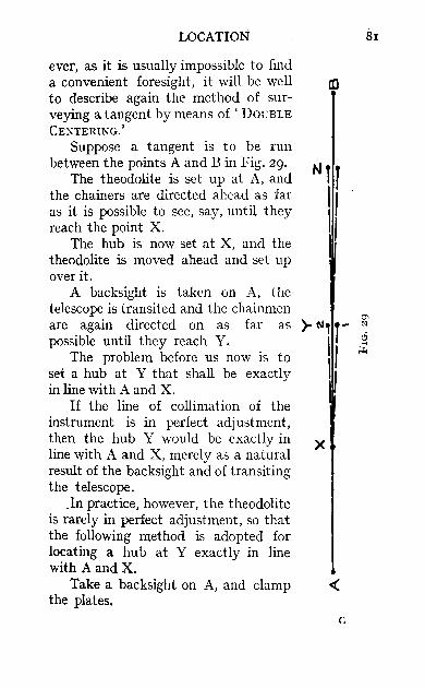
LOCATION
ever, as it is usually impossible to find a convenient foresight, it will be well to describe again the method of surveying a tangent by means of 'DOUBLE
CENTERING. '
Suppose a tangent is to be run between the points A and B in Fig. 29.
The theodolite is set up at A, and the chainers are directed ahead as far as it is possible to see, say, until they reach the point X.
The hub is now set at X, and the theodolite is moved ahead and set up over it.
A backsight is taken on A, the telescope is transited and the chainmen are again directed on as far as possible until they reach Y.
The problem before us now is to set a hub at Y that shall be exactly in line with A and X.
If the line of collimation of the instrument is in perfect adjustment, then the hub Y would be exactly in line with A and X, merely as a natural result of the backsight and of transiting the telescope .
.In practice, however, the theodolite is rarely in perfect adjustment, so that the following method is adopted for locating a hub at Y exactly in line with A and X.
Take a backsight on A, and clamp the plates.
81
x

82 FIELD ENGINEER'S HANDBOOK
Now transit the telescope and note the intersection of the cross-hairs; let it be the point I.
Unclamp the instrument and revolve bodily until the telescope is again sighted exactly on A, and clamp the plates.
Now transit the telescope again. This time, since the line of collimation is slightly
out of adjustment, it will intersect at the point 2.
Bisect the distance between I and 2, and the point Y will be in line with A and X.
The theodolite is now set up over Y, and the process is repeated to locate Z and so on.
This process is called' DOUBLE CENTERING.'
The head chainman must always be prepared for this process, when he receives the signal to set a hub.
He must watch the instrument man carefully and give him first the point I and then the point 2; and then the chainman must himself bisect the distance and hold a pole on the new point so that the instrumentman can sight his instrument on the new point.
Practically the most important part of the location is the fixing of the grade lines upon the profile.
At night the locating engineer lays before him the profile of the line and fixes upon it the grade lines, endeavouring to equalise the amount of excavation and embankment.
For any railway there is always a maximum gradient, which must not be exceeded except under very exceptional circumstances. This maximum gradient is only allowed upon tangents, because, when a train goes round a curve, there is resistance over and above that caused by the gradient itself. Hence compensation of grade must be made for curvature.

LOCATION
The amount of compensation is settled by head~ quarters, and varies in different railways.
Let us now return to the subject of joining up the tangent by curves.
Joining up Tangents by Curves.-The degree of the various curves is of course decided upon by the locating engineer. The actual work of running them in being left to the instrumentman.
The majority of curves, in fact all those sharper than a I O curve, are' spiraled.' 1 That is to say, transition curves are fitted both at the beginning and the end of the circular curve.
For the sake of simplicity, the autbors will first consider the joining up of two tangents by means of a simple circular curve, leaving to another chapter the explanation of the practical transition curve or Railway Spiral.
The problem before us, then, is the running in of a simple curve between two tangents.
Let the Degree of Curve be zO. The first thing to do is to set up the theodolite
over the P.I. or Point of Intersection of the tangents, and to carefully measure the intersection angle I.
This should be done with the greatest care and accuracy.
Suppose the angle measures 78°, then we know that the angle subtended by the wbole arc of the curve at the centre is 78°. Hence the sum of all the
J This refers to American practice, where a maximum speed is taken, and m !lst not be exceeded on any curve. In England, however, the same principle does not apply: the
. flatter that a curve is, the faster do the trains run: conse-quently transition curves arc fitted to flat curves and not to very sharp curves.
GZ

84 FIELD ENGINEER'S HANDBOOK
deflection angles will be ! = 390 • The deflection 2
angle for a chord of 100 feet is E = 10. 2
Therefore the curve will be made up of 39 chords of 100 feet and the Length of Curve will be 3,900 feet.
Having measured I, the next thing to do is to find the Tangent Distance, T, which will be 2319'9'. (See Table 11.)
This distance must be very carefully chained from the P.L along each tangent; and on each a hub must be set with the help of the theodolite, exactly on line, so that the distance measured between the tacks is equal to T.
The theodolite can now be moved to the P.C. The curve is now run in either' directly' or it may
be ' backed in.'
To Run in the Curve Direetly.-Place the zeros of the scales together and sight on the P.L
Deflect 1° from the tangent, and direct the head chainman where to drive his first stake, the rear end of the chain being held over the P.C. Now deflect 2°, and again direct the head chainman where to drive stake 2, the rear end of the chain being held at the stake I.
In this way the whole curve is run in. If it should happen that there are not an even
number of stations in the curve--for instance suppose a length of 75 feet is left between the P.T. and the last point set on the curves-then the deflection for
75 feet can be calculated; it is & X 60' = 45'. 100
Always run in a curve so that the ends of the
LOCATION
roo-foot chords correspond with even stations in the chaining. Hence if the chainage of the P.C. is 640 + 25' it is plain that station 641 will be 75 feet along the cun'e. Therefore the deflection for 75 feet, namely 45', is calculated, and this is the first deflection angle and will determine the point on the curve at station 641. It is advisable to set off this 45' on the vernier on the opposite side of zero to that in which the deflection angles of 1° will be set off, and to look at the P.I. Then the vernier will read zero on the first station on the curve. Deflection angles of one degree can now be made from this point (641 + 00), thereby locating the stations all round the curve.
In practice, it is advisable to locate the 50-foot points as well as the Ioo-foot stations. Suppose that, in this example, the P.e. is at 640 + 25 and that the fourth station on the curve has been located. The head-chainman is standing at 644 + 00, and the rear-chainman is standing at 643 + 00. The chain lies between them. If the curve is to the right, and the instrument man had his vernier at zero when looking at the first station on the curve (641 + 00), his vernier would now be at 3° 00'. Fig. 30 (a) will make this clear.
In order to locate 643 + 50, the instrnmentman would turn back his vernier to 2° 30', and the headchainman would come back to the 50-foot mark on the chain.
To Back in a Curve.-Set up at the P.T. with both plates clamped at zero, and sight the P.I. Unclamp the upper plate and turn off the total
deflection angle; that is, ~ = 39°. The cross-hairs 2
should now intersect on the P.C. The deflection
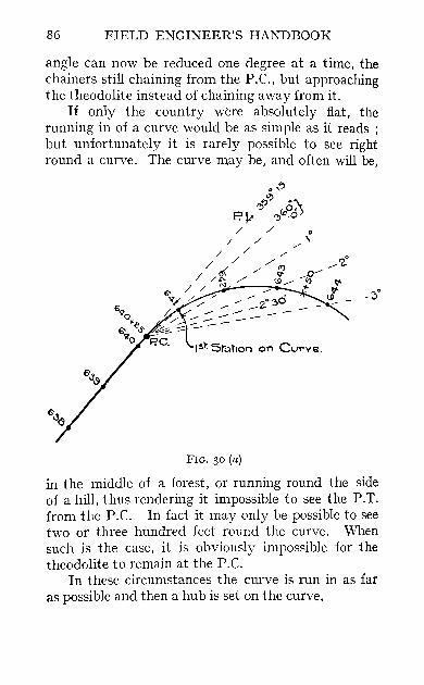
86 FIELD ENGINEER'S HANDBOOK
angle can now be reduced one degree at a time, the chainers still chaining from the P.e., but approaching the theodolite instead of chaining away from it.
If only the country were absolutely flat, the running in of a curve would be as simple as it reads ; but unfortunately it is rarely possible to see right round a curve. The curve may be, and often will be,
FIG. 30 (a)
in the middle of a forest, or running round the side of a hill, thus rendering it impossible to see the P.T. from the P.C. In fact it may only be possible to see two or three hundred feet round the curve. When such is the case, it is obviously impossible for the theodolite to remain at the P.C.
In these circumstances the curve is run in as far as possible and then a hub is set on the curve.

LOCATION
The greatest care and accuracy in chaining must be used when setting a hub on a curve.
Also, the hub is located not by chaining from the last point in the curve,_but by chaining directly from
FIG. 30 (b)
the P.e. to the hub. (See formula for long chords, page 65; see also Exercise 2, page 92.)
Having set the hub, the theodolite is moved and set over the new point. The deflection angle that was used to locate the new hub is now set off on the scale, but on the opposite side of the zero.
The :plates are clamped together and the telescope

FORM OF FIELD BOOK FOR PRELIMINARY SURVEY.
---- - --------~-----
I Deflection Angles. I Bearings.
Statwn. Reading. --, -- - Remarks.
_____ __ _ _ Left. ~~~~_ Magneti",--I Calculated.
0+00 I4°06' I4°06' N I030'E N 14'06'W The Theodolite was set , up with verniers at i 0° and looking due
I I N~lli I4 + 60 42'I6' 280IO' II N 27°00' W N 42'16' W Hub on top of hill. 52 + 80 'I 2'00' 1 40016' N 13'30' E N 2°00' W Milepost 1.
149 + 20 331'20' 83°00' S 83'30' E N 81°00' E I
The Magnetic Declination has been assumed I5'30' West of North.
FIG. 31
00 00
"rj I-<
t:I:J
b t:I:J Z o ..... Z t:I:J t:I:J ~ r.iJ ::r: > Z tJ ttl o o p:;

II Length
of I Deflecti on Angles" Course.
Station"
0+00
8 + 89"4
27 + 47"2
55 + 55"9
7I + 53"I
889"4
I857"8
2808"7
I597"2
2525"4 96 + 78"5 I
I728"7 II4 + 07"2
I263"I I26 + 70"3 II
3785"5 I56 + 25"3
I64 + 55"8 536"3
~I~~~lt. r030'
58°3 0 '
9° 00'
34 0'
16°3°'
50°00'
55°00"
70°3 0'
22°0'
FORM OF TRAVERSE TABLE"
Bearing.
S 88°30' W
IS 3°°00' W
1 S 64°00'W
: S 26°00' E
S 9°30' E , S 40030 'W I
N 84°30'W I
N I4°00'W
N 8"00' E I
I Latitude" Departure" 'I
~~~-I--s-" - --;!----;~,
53°"7
23"2
I609"0
I231"3
I435"4
2490 "3
I3 I 4"7
FIG" 32
I
888"611
92 9"0
2524"7
700"2
4 I 6"7
I122"8
I257"2
9I 5"9
74"6
Co·ordina es.
Total Latitude" J Total ~epartu:-I
N" I_s" J E" I w" I
° 23"2
I632"2
2863"5
142 98"9 :
6789"2 1
8I03"9
7982 "8
43°9"7
, 3779"0
° 888"6
I8I7"6
4342"3
3642"I
3225"4
4348"2
56 0 5" 4
6521"3
6446"7
H
o () ;J> >-l H o Z
00 \0

go FIELD ENGINEER'S HANDBOOK
is sighted on the point just vacated. The lower plate is damped and the upper plate undamped.
The zeros are now brought together again, and the vernier will be reading zero and the line of collimation will also be on a tangent to the curve at the point over which it is set.
The running in of the curve can now be continued as before. Consider Fig. 30 (b).
This operation of 'GETTING ON TANGENT' will explain itself by reference to the above figure. A curve is to be run from P.e. to P.T., but an obstacle prevents a sight being taken on the P.T.
The curve is run in as far as the 4th chord, where a hub is set at 4. Position I shows the telescope with the deflection angle turned off to locate point 4. Notice that the deflection is on the right-hand side of the zero.
On moving to the hub at 4 the deflection angle is . turned to the left of zero, and the telescope is sighted ·on the P.C.
It will be seen at once from the figure that by bringing the telescope back to zero,the line of collimation will be made tangential to the curve at point 4, and hence the instrument will be in a position to continue deflections and to run in the rest of the curve.
The located line is plotted by means of Latitudes and Departures in the usual way.
For rough work, the line may be plotted by means of the length of the courses and the natural tangents of the angles between the courses. The general work in the drawing-office can only be learnt on the spot. Good working plans are required, not fancy drawings with illuminated titles. The centre line of the railway is usually drawn in red. Contours are shown in

LOCATION 91
burnt sienna, water-courses and rivers in blue, and all other drawing in black. A form of Field Book for a preliminary survey is shown above (Fig. 31).
A form of Traverse Table is also given (Fig. 32).
EXERCISES
1. A 4° curve is to connect two tangents, whose intersection angle is 300 45'. Find the Tangent Distance and the length of the curve. If the curve goes to the right, find the readings that must be set off on the vernier to locate loo-foot stations-the vernier is to read zero when the telescope points at the first station on the curve-
(a) if the station age of the P.C. is 31 + 00 ; (b) if the station age of the P.C. is 64 + 72 '3.
Answer.-Tangent Distance = 393'9'. Length of curve = 768'7'.
(a) 0° 00', P.I. and 3 1+00 2° 00', " 32+00 4° 00', " 33+00 6° 00', " 34+00 8° 00', " 35+00
10° 00', " 36+°0 12° 00', JI 37+00 14° 00', " ,,38+00 15° 221', P.T. and 38+68'7
(b) 359027', P.I. and 64+72'3
0° 00', " 65+00 2° 00', " 66+00 4° 00 ', ,,67+00
6° 00', " 68+00 8° 00', " 69+00
10° 00', ,,70+00 12°00', " 71 +00
14° 00' " " 72+00 14° 49r, P.T. and 72+41'0
2. A 4° curve runs to the left. The intersection angle of the tangents is 33°. The stationage of the P C.=II7+94·3. Find the Tangent Distance, and the stationage of the P.T. If it is impossible to see from theP.C. farther than the fifth station on the curve find the vernier readings on all the stations. Find als~ the long chord to locate the fifth station.

92 FIELD ENGINEER'S HANDBOOK
Answer,-Tangent Distance = 424'3'. Stationage of P,T, = I26+19'3
Theodolite at
P,C. II7+94'3
Lookhag at
P,I.
I Vernier Reading
1--- 00 07'
0° 00'
3600 00' II9+00 3580 00' 120+00 3560 00' I2I+OO 354000' 122+00 . 3520 00'
P,C, I 80 07' Now Transit Tel,escope
123+00 ' 3580 00' 124+00 3560 00' 125+00 354000 ' 126+00 3520 00'
P.T. I26+ I9'3 35 Io 37'
Long Chord=zR sin 80 0]' (for fifth station) = 404'6'.
NOTE -If the reader is unable to layout these curves actually in the field, he is recommended to do them on paper, using nothing but a scale and protractor. A good scale is I inch = 50 feet.

CHAPTER VIII
THE RAILWAY TRANSITION CURVE
THE rails of a railway are made perfectly level transversely when the track is straight, that is on a tangent.
On a curve, however, the outer rail must be higher than the inner rail, in order to prevent the train from being overturned by so-called' centrifugal force.'
The amount by which the outer rail is higher than the inner rail depends both on the sharpness of the curve and on the maximum speed at which the train is to be run.
Consider Fig. 33, which represents a pair of rails on a curve, of which the outer rail has a super-elevation equal to SQ. Let X be the centre of gravity of a coach travelling round the curve, with a uniform velocity of v feet per sec.
When the coach is moving round the curve, there will be two forces acting-
(r) The Weight acting vertically downwards. (2) The Centrifugal Force acting radially outwards.
In order that the coach shall not leave the track, it is plain that the resultant of these two forces must act between the rails, and if possible be perpendicular to the cross-section of the track, so that there may be no side thrust on the rails.

94 FIELD ENGINEER'S HANDBOOK
At the same time, should the coach come to a standstill on the curve, it is necessary that the downward vertical force due to the weight above shall also fall between the rails.
When the conditions are such that the Resultant Force is perpendicular to the track, we have two similar triangles PQS and XYZ.
FIG. 33
SQ ZY PQ=XY
But SQ is the Super-elevation.
C"NTRE:Ot" c.Uf\'VIt..
PQ is the Gauge of the Track (approximately). ZY is the Centrifugal Force. XY is the Weight.
Therefore,
SQ ZY PQ=XY'
Super-elevation or , Gauge of Track
Centrifugal Force Weight
Now in practice, the Super-elevation is limited(1) By the Comfort of Passengers. (2) By the case of a Train Stopping on a Curve.

THE RAILWAY TRANSITION CURVE 95
e Now, - = tan a.
d Wv2
So e gr v2 -=tana=-=-d W gr
where e = Super-elevation in feet. d = Gauge in feet (approximately). v = Velocity in feet/sec. r = Radius of the Curve in feet.
Let us consider the case of a train travelling at 45 miles per hour round a curve of Radius 20
chains.
Then
The Gauge = d = 4' 8r' = 4'7 feet, 45 m. p. h. = 66 feet/sec. = v
20 chains = 1320 feet = r
d gr
whence v~d
e=-gr
.. e 66 X 66 X 4"7 32'2 X 1320
= 0'482 feet = 6 inches.
It is essential that, by the time the train enters the circular curve, the full elevation of the outer rail shall have occurred.
Before transition curves were introduced, it was the custom, in order to effect this, to commence the elevation of the outer rail on the tangent itself, so that by the time the train entered the curve the full elevation had been obtained. But this resulted in a

96 FIELD ENGINEER'S HANDBOOK
sharp jerk occurring when the train suddenly entered the curve from the tangent.
The problem to be overcome therefore developed into this:
To make the process of leaving the tangent and entering the curve very gradual; and at the same time to gradually elevate the outer rail so that by the time the train entered the circular curve, the full superelevation had taken place.
This problem is solved by inserting a curve between the circular curve and the tangent, the curvature of which increases from zero at the point of tangent to the full degree of the circular curve at the end of the transition curve.
It is on this curve that the whole of the superelevation takes place.
The curve should be very flat at the tangent end, and should gradually increase its curvature until it obtains the same curvature as the circular curve.
The Searles Spiral is constructed on a series of chords of equal length.
The ends of the chords are located by deflection angles.
These chords subtend circular arcs, and the degree of curve of the first arc is made the common difference for the degrees of curve of the succeeding arcs.
The chords may be of any length whatever, so long as they are all equal; but the deflection angles are the same for all chord lengths.
Hence, spirals of different sizes are all reducible to the same shape by altering the scale.
No attempt will be made to go into the theory of the 'Searles' Spiral; but this can be found, together with tables for locating 500 Spirals, in , The Railroad Spiral' by W. H. Searles, c.E.

THE RAILWAY TRANSITION CURVE 97
The object of this chapter is merely to explain how these spirals are applied to circular curves, to enable the reader to run in such curves without any difficulty.
The Searles Spiral is the standard used by the Grand Trunk Pacific Railway. In this chapter the length of chord selected has been 33 feet, but it must be remembered that any other length can be used without altering any of the deflection angles. Fig. 34 shows a spiral curve.
FIG. 34
Special care should be taken to remember the notation. Going in the direction of the chainage we have-
(I) The Point of Spiral, P.S1. (2) The Point of Curve, P.C. (3) The Point of Spiral, P.Sz. (4) The Point of Tangent, P.T.
Before the curve can be spiraled, there must be given the intersection angle of the tangents and the degree of the circular curve.
For example, let it be required to run in a 4° curve with spirals at both ~ends.
Let I = 62° 18'. H

98 FIELD ENGINEER'S HANDBOOK
Tbe rule for determining the number of chords in the spiral is as follows:
No, of Chords = twice the Degree of Curve less one,
This rule must only be applied when 33-foot chords are being used, If other chords are to be used, the number of chords must be found from Searles' Tables,
Hence our spiral is to have seven 33-foot chords, Next we must locate the P'sI' and P,T, by actual chaining from the P,I.
The Tangent Distance T s for a spiral curve is not quite the same as the Tangent Distance for a circular curve,
Tangent Distance, T s = T + Q + P tan t A
where T is the tangent distance for the original circular curve,
Q is a constant (see Table A), P
.6. is the total central angle = I. TABLE A,
I I 'I Length [ , I R t,angle 'I; 'Ii Et::d Degree No. of of Splral off-set X, Y Q used to
of 33-fool . 1 angle I p () I ') ') C 'Ch d sp,ra S ' ft, (ft, (ft'. locate urve I or s (ft.) 'I' (ft,) P,C,
(ft,)
1-1-0- -1-~I---:-i~ ~133'oo! 16'33 ---;~ 1 °30' I 2 66 1 30' '09 '24 66 '00 32 '67 66'0 2° ,3 99 1°00' '24 '67 I 99'00 49'00 99'0 2°30' 4 132 1°40' '47 1'44 132 '00 65'34 132'0 3° 5 165 2°30' '82 2'64 164'97 81'65 165'0 3°30 6 IC)8 3°30' 1'31 4'37 197'92 97'97 198'0
! 4° 7 23 1 4°40' 1'97 6'72 230'84114'28230'9 '4°30' 8 264 6°00' 1 2 '80 9'78 263'6913°'57' i63'9
5° 9 297 7°30' 3'85 13'66 296'46146'84 296'8 5°30' 10 330 9010/ , 5'13 18'441'329'12163 '10 329'6 6° II 363 ,11°00 / , 6'66 24'22 361'61179'32362'4
, I
The above table gives all the necessary functions or elements of the 33-foot chord spiral for curves of 2° to 6° inclusive.

THE RAILWAY TRANSITION CUf(VE 99
In this case T = 865 '8' Q = II4'28' P = 1'97' Ts= 865'8 + II4'3 + 2'02 tan 31° 09'
= 98r '3'
Tbis distance is carefully chained from the P.I. and hubs are set on lines fixing the P.S1. and P.T.
The following order of carrying out the various operations will be found to save time in the field.
The theodolite is set up over the P.T. and the spiral is run in just as a circular curve, but using chords of 33 feet and deflection angles found in Table B, namely oS', 12'5', 23', 37'S', 55', 1° 16', 1° 40'.
The point determined by the deflection 1° 40' will be P.S2., and in practice it is more accurate to chain the long chord, found in Table A, from the P.T. to this point.
The theodolite is now moved to the P.S1. and the spiral is run in in exactly the same way, thus fixing the P.e.
Now set up over the P.e. and ( get on tangent: in the same way as described in Chapter VII. The angle to be turned off on the opposite side of zero will be 3°, found at the top of the column marked , Theodolite at 7 ' in Table B.
Having got on tangent, the 4° curve is run in, in the usual way, by deflections of 2° for each chord of 100 feet, the curve being continued to the P.S2.
With proper closure on this point the location of the curve is complete. It must here be mentioned that the fact of introducing the two spirals is to reduce the length of the original circular curve.
The total central angle is therefore divided into three parts. H 2
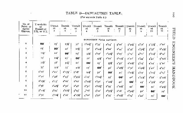
No. of Theodolite Transit Point or or Spiral Transit at at
Station. P.S," or P.T. r
0 00' oS'
I oS' 00'
2 I'l' IO'
3 23' 22i'
4 371' 38'
5 55' 57!'
6 1°16' 1°20'
7 1°4-0' 1°46'
8 2°071' 2°15'
9 2°38' 2°471'
10 3°121' 3°23'
n 3(150 ' 4°021'
TABLE B-DEFLECTION TABLE. (Fot' use with. Table A.)
Transit Transit Transit Transit Transit Transit at at at at at at 2 3 4 5 6 7
DEFLECTION FROM TANGENT.
I7!' 37' 1°02l' 1°35' 2°14' 3°00'
IO' 271' 52' I O Z2!' 2°00' 2°44'
00' IS' 37!' IOOt 1°421' 2°25'
IS' 00' 20' 47!' 1°22' 2°02l'
3'1' .0' 00' 25' 57i' 1°37'
53' 4'1' 25' 00' 3°' IOO71'
1°17.' 1°08' S2t' 30' 00' 35'
1°45' I0371' 1°23' 1002!' 35' 00'
2°16' 2°10' I057l' 1°38' IOI2!' 40'
2°50' 2°46' 2°35' 20I7t' 1°53' I 0 22i'
3°271' 3°25' 3C11 6' 3°00' 2°371' z008'
4°08' 4°071' 4°00' 3°46' 3°25' 2°57l'
Transit Transit at at 8 9
3°52!' 4°52 '
3°35' 4°32t'
3°14' 4°10'
2°5°' 3°44'
2°22i' 3°15'
1°52' 2°421' 1°171' 2°°7'
40' I 0 27!'
00' 45'
45' 00'
I032l' 50'
2°23' 1°42'
Transit Tro at a IO
5°57i' 7°
5°37' 6°.
5°121' 6°,
4°45' 5°
4°14' 5°
3°4°' 4°·
3°02!' 4°'
2°22' 3°:
1°371' 2°:
50' I O,
00'
55'
.nsit
0'
71'
.'
.f 0'
4'
5'
21'
7'
71'
5'
'0'
... o o
'"l:j ...... tIj
b ~ c;J ...... Z tIj tIj ~ rJi :r: > z t:J to o o p::

THE RAiLWAY TRANSITION CURvE 101
Each spiral subtends a certain angle called the Spiral Angle, found in Table A. Hence to find the central angle subtended by the circular curve allowing for the spiral angles:
Let ~ be total central angle. ~c be central angle of Circular Curve. ~s be Spiral Angle (got from table).
Then ~c = ~ - 2 ~s
:. ~c = 62° 18' - (2 X 4° 40') = 52° 58'
Hence we can now find the length of the circular curve, namely 1324'2 feet. .
The length of the spirals themselves will be 7 X 33 = 231 feet.
Hence, to find the STATIONING ALONG THE CURVE:
Let the Station of the P.S1. be 319 + 27. Adding the length of the Spiral, we get P.C. =
321 + 58. Adding the length of the Circular Curve, we get
P.S~. = 334 + 82'2. Adding the length of the Spiral, we get P.T. =
337 + 13'2. Just as we saw in the case of the circular curve,
it may not be possible to see all round a spiral; consequently, the theodolite may have to be moved up to a point in the spiral.
For instance, suppose it becomes necessary, after locating the first four chords of the spiral, to move up to point 4.
To get on tangent, turn off 1° 02 '5' on the opposite side of zero; the angle being found at the top of the column (Table B) marked 'Theodolite at 4.' Look back on the P.S1, Bring the vernier to zero.

102 FIELD ENGINEER'S HANDBOOK
Transit and continue running in the remaining points of the spiral by means of the deflection angles 25', 52!" 1° 23'. These being found in the same column opposite points 5, 6, and 7.
Should it be necessary to fix an intermediate station on any spiral chord, as, for instance, to locate an even station, this may be done by considering the chord between such spiral points, in which the extra stationing will occur, as a chord of a circular arc; and, consequently, the deflection angle to establish such a point would be obtained by interpolation.
For example, suppose the chord point 4 in the above example came at station 620 + 92.6, and it was desired to locate station 62I.
With the theodolite at P.S1., the deflection angle to point 4 (620 + 92 ·6) is 37!'; to point 5 it is 55'· The difference is 17f.
The subchord 620 + 92.6 to 621 = 7"4 feet. Therefore the deflection angle for 7"4 feet is-
7 ·4 X 171 '--_-'--2 minutes
33
Added to 37f, this gives the deflection angle to the station 621 as 41 f.
It is usual to fit spirals to all curves of 2° and upwards, and this is done during the final location.
The following is a short proof that the Searles Spiral fulfils the requirements of a transition curve, with regard to shape :~
The requirement of a transition curve is that its curvature at any point should be proportional to the length from the P.S1. to that point.
For an,)! curve, the curvature at any point is the recipro·cal of the radius at that point.
For any 'flat' curve, such as a curve less than
THE RAILWAY TRANSITION CURYE 103
about 60 , the degree of curve is proportional to the reciprocal of the radius (see page 61).
Therefore, for any fiat curve, the Curvature is proportional to the Degree of Curve.
Suppose now that the fiat curve is a Searles Spiral. In a Searles Spiral we know tLat the Degree of Curve at any point is proportional to the length from the P.S1.; therefore, the Curvature at any point is proportional to the length from the P.S1.
Therefore the Searles Spiral is a suitable transition curve.
The Cubic Parabola.-A common transition curve, where no special type specified, is the Cubic Parabola.
The equation of this curve is y = kX3
dv hence the slope d~ = 3kx2
d2y I and the curvature dx2 = r = 6kx
.'. k=~ 6n
form of has been
(1)
(2)
(3)
(4)
As (from equation 3) the curvature is approximately proportional to the length (the length is very nearly x and is taken to be the same), the curve is a good transition curve.
First assume a length for the curve; let it be 316 feet. This length is quite arbitrary; it is either decided upon by the engineer, or calculated from some empirical formula. l The curve must be of such a length that the super-elevation will not be too sudden.
1 L =,.; R h'ls been proposed; where L is the length, ann R the radius of the curve in Gunter chains.

104 FIELD ENGINEER'S HANDBOOK
Let the radius of the circular curve be lOOO feet. The curvature at the end of the cubic parabola shall be the same as the curvature of the circle.
Apply equation 4 to be the last point on the parabola, we have: r = 1000, X = 316 (approx.)-
.'. k = I 6 X 1000 X 316
3163 .'. y = 6 6 = 16'66 feet
X 1000 X 31 (this is the offset from the tangent to the end of the parabola).
FIG. 35
This figure having been obtained, the offset for any intermediate point may be found. For instance, supposing a point a quarter of the way along the parabola (see Fig. 35) is required, we multiply the final offset (16'66 in this case) by the cube of one quarter.
To run in the circle, it is necessary to get on tangent at the final point of the parabola (see Fig. 36)
: = tan cp (for the final point)
= 3 kX2 (from equation 2)
3 kX3 3Y = -- = _. = 3 tan e x x
t A. 3 X 16'66 d t e 16'66 .. an 'f' = 316 ,an an = 316
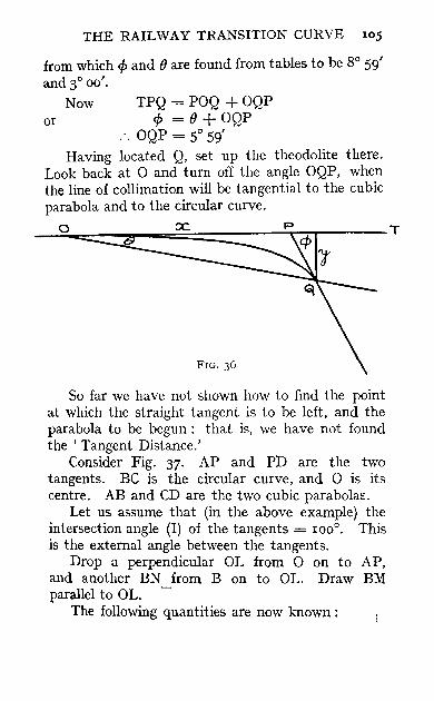
THE RAILWAY TRANSITION CURVE 105
from which cp and () are found from tables to be 8° 59' and 3° 00'.
or Now TPQ = POQ + OQP
cp = () + OQP ... OQP = 5° 59'
Having located Q, set up the theodolite there. Look back at 0 and turn off the angle OQP, when the line of collimation will be tangential to the cubic parabola and to the circular curve.
__ ~O~~~ __ ==~==== __ ~~ ______ T
So far we have not shown how to find the point at which the straight tangent is to be left, and the parabola to be begun: that is, we have not found the • Tangent Distance.'
Consider Fig. 37. AP and PD are the two tangents. BC is the circular curve, and 0 is its centre. AB and CD are the two cubic parabolas.
Let us assume that (in the above example) the intersection angle (I) of the tangents = 100°. This is the external angle between the tangents.
Drop a perpendicular OL from 0 on to AP, and another BN from B on to OL. Draw BM parallel to OL.
The following quantities are now known:

106 FIELD ENGINEER'S HANDBOOK
or
or
AM = X, the final length of the parabola (for all practical purposes).
MB = Y, the offset at the final point. OB = R, the radius of the circular curve.
LOP = !, half the intersection angle. 2
LOB = cp, the final slope of the parabola (i.e. the angle that it makes with the tangent).
FIG. 37
We want to find AP.
Evidently AP = AM + MP AP = AM + LP - LM
I AP = AM + (LN + NO) tan-- - NB
. 2

THE RAILWAY TRANSITION CURVE I07
or Tangent Distance
= X + (Y + R cos ¢) tan ~ - R sin ¢ 2
In this case, X = 316'; R = 1000'; Y = 16'66' ; ¢ = 8° 59'; I = 100° .
. '. Tangent Distance = 316 + (16'66 + 1000 cos 8° 59') tan 50°-
1000 sin 8° 59' = 316 + (16'66 + 98T74) tan 50°- 156'14 = 316 + II9TO - 156 '2
= 1356'8 feet.
NOTE.-The angle which we have called ¢ in dealing with the cubic parabola is the same as the spiral angle S that we have used in the Searles Spiral. The formula for the Tangent Distance to a Searles Spiral can be obtained in a way just like that of page I06. P and Q in Table A were calculated from the formula'! :
P = X - R -t- R cos S. } Q = Y -RsmS.
Notice that in the cubic parabola diostances along the tangent have been denoted by X, but that in the Searles Spiral distances along the tangent have been denoted by Y.

CHAPTER IX
RAILWAY CONSTRUCTION
(NORTH AMERICAN PRACTICE)
WHEN a railway has been finally located, it is usual to divide the line into sections or ' Residencies,' the lengths of which are determined by the nature and amount of construction that will be necessary on each.
Where the country is flat or rolling, a residency from twelve to fifteen miles long is common. In mountainous country the residencies will, of course, be much shorter.
Each residency is in charge of a resident engineer, who is responsible to an assistant engineer.
The division engineer is usually directly under the chief engineer of the railroad. Construction parties are formed and sent out about the first week in April.
Each resident engineer is supplied with a plan of the railway and a profile of his residency, showing grade lines, curves, bridge and culvert notes, notes of all special \vork such as changes of water courses, riprap of banks and the location of road crossings, etc.
The Construction Party.--A construction party generally consists of-
RAILWAY CONSTRUCTION 109
Resident Engineer. One Instrumentman. One Staffman. Two Chainmen. One Axeman. One Cook. One Team and Driver.
The members of the party are supplied with passes on the railway to the station nearest the line to be constructed.
The instruments taken usually comprise-
One Theodolite. One Level. One Staff. Two IOO' Steel Bands. One Tape. Six Poles.
Tents and supplies are taken, and new food supplies are sent out every month.
Camping-ground.-On arriving at the residency the first thing to be done is to select a suitable camping-ground, near the line, about the middle of the residency and near good water supply.
Immediately on arrival at the residency the resident engineer notifies headquarters of his postal address.
Re-running Alignment.-The first work of the construction party is to re-run the alignment of the survey.
Frequently the original survey will have been made in the winter time, and the stakes denoting stations will then have been stuck in the snow.
lIO FIELD ENGINEER'S HANDBOOK
Consequently, the snow having melted, these stakes will now be found lying flat on the ground.
The resident engineer takes the theodolite and proceeds with his party to one end of the residency.
He then re-surveys the line, according to his plan, straightening out the tangents and running in the curves carefully.
The construction chain age must be made to agree with the location chainage, even if it is found that the location chain age is somewhat inaccurate.
Check Levels-While the resident engineer is re-running the alignment, the instrument man runs check levels from one end of the residency to the other. He must check on the location bench marks and place new ones at least every thousand feet along the line, transferring to a place of safety any bench marks that would be liable to destruction during construction.
It is important to place a bench mark close to each bridge for convenience during its construction.
The resident engineer is not allowed to make any change in the gradients, alignment, location or size of bridges, culverts, etc., but he will naturally call his superior's attention to any possible changes that he may consider beneficial or economical.
Clearing and Grubbing --In country where the line runs through a forest, clearing and grubbing is the first ,York of a contractor.
All trees within the limit of the railway are felled, and the tree stumps are torn up.
It will, of course, be obvious that the stumps or roots are not torn up where a deep cut is to be made, but they are removed as the excavation proceeds.

RAILWAY CONSTRUCTION III
The engineer needs to keep his eyes open lest contractors leave tree stumps in the ground, and hurriedly conceal them with embankment.
Various results of such negligence will suggest themselves to the reader.
Where embankments are very low, say only two feet or so, contractors should be prevented from building the embankment with grass sods.
Referencing Hubs --Before allowing any construction to commence the engineer should carefully reference all his hubs on tangent, and all p.e.s. and P.T.s.
All traces of the survey will, of course, A be destroyed as soon as construction commences, and hence it is essential that it should be possible to replace all hubs by means of reference hubs.
Various methods of referencing are adopted. For example, in Fig. 38.
Let A be the point of tangent of a curve. Suppose it is where an embankment is to be built.
Set up the theodolite over A and turn off any convenient angle from the centre line, and set two hubs in line, well away from the point A.
Now turn through a fairly large angle, say 800 ,
Il2 FIELD ENGINEER'S HANDBOOK
and set two more hubs in line. Then when the embankment is built and the hub A has been covered up, the P.T. can be reset as follows:
Set up over B, sight on D and line in two wooden pegs, about 6 feet apart, on the embankment.
Now set up over C, and sight on E and set a hub on the embankment in line with the two pegs already set.
In this way the intersection of BD and CE produced will determine the original P.T.
All the hubs on the survey are referenced in this way before construction commences.
It will occur to the reader that the most convenient place for a hub will be at a 'grade point: where there is neither cut nor fill; hence in 'practice before hubs are referenced they are transferred~to grade points.
Cross-sectioning, Setting Slope Stakes. -- When the alignment has been completely re-run and also the levels checked, it is usual to commence crosssectioning the line at once.
It will be well, therefore, to devote some space to the subject of cross-sectioning, and setting slope stakes.
The profile of the residency shows all the grade lines and also the elevation of the grade.
Hence by consulting the profile it is easy to calculate the elevation of any point on the grade line.
Knowing this and the elevation of the natural surface of the ground, it is a matter of simple subtraction to determine the cut or the fill at that spot.
For instance, let Fig. 39 represent the profile of a line, the grade of which is -+- 0'5: that is to say, the grade rises 0'5' in IOO', Let the elevation of the grade at station IOOO be 2264'75.
What will be the elevation at station 1024 ?

RAILWAY CONSTRUCTION lIS
The distance of A from station 1000 is 2400.
The grade rises 0'5' in every 100'.
Therefore the rise in 2400 = 0'5 X 24 = 12 feet. Therefore the elevation of A = 2264'75 + 12 =
2276'75, The actual elevation of the ground at B can be
determined with the level. Suppose it was found to be 2270'80, then we see that the depths of embankment must be 2276'75 - 2270'80 = 5'95 feet.
Hence the depth of cut or fill at any point of the line is easily calculated.
/\A~ I :7 \V <:::::::::::7-I I ~ I r
1040 1()30 1020 1010 1000 SOO
FIG. 39
Knowing this, we have to find next where the toe of the embankment or the top of the cut will intersect with the ground.
To find this, it is necessary to know the width of the cut or embankment, and the slope of the sides,
For ordinary earth a slope of It' horizontal to I' vertical is taken for both cuts and fills i while for a single track the top of embankment is usually IS feet wide and the bottom of cuts 20 feet to allow for side ditches in the cut.
In cross sectioning we have two cases to consider: (I) When the ground is level. (2) When the ground slopes or is irregular trans-
versely. . I

114 FIELD ENGINEER'S HANDBOOK
Let Fig. 40 represent an embankment, the natural ground being level transversely.
To Determine the Points Band C and Mark them on the Ground.-Set up the level and take a reading on a bench mark.
Determine the height of instrument in the usual way.
Now direct the staffman to hold the staff on the centre stake at A.
The reading on the staff subtracted from the H.I. will give the elevation of the point A.
F=-- D,-_----------= =-D2--=-=:; I ! & I
Po \ F >0 1 F'2. I 'i'?:; 0(0 I • I I " :
8 A
FIG. 40
Subtract this elevation from the elevation of the grade calculated from the profile.
This will give the flll F. Since the ground is level transversely Fl = F2 = F. Then the distance out from the centre to B or C
is given by I! F +! width of the road bed. For example, let F = 6 feet. Then Dl = 6 + 3 + 7'5 = 16'5· Hence stakes would be driven in at Band C at a
distance of 16'5 feet from the centre stake. The notes of such a cross-section would be entered
up in the cross-section book as follows:
- 6'0 -6'0 - 6'0 --i6~5 16'5'

RAILWAY CONSTRUCTION 115
The numerators denoting the cut or the fill, and the denominators denoting the distance out.
The + sign denotes a cut: the -sign denotes a fill.
Unfortunate ly level cross - sections are few and far between, and directly a transverse slope enters into the question, the difficulty of cross-sectioning increases rapidly.
Let us now consider the cross-sectioning of any crosssection whatever, no matter what the transverse slope of the ground may be.
The method of cross sectioning about to be described is known as the • Grade Staff Method.' In this method the engineer works out what the reading on the staff would be if it were held at grade,
I 2
Il6 FIELD ENGINEER'S HANDBOOK
that is to say, on the top of the finished embankment, or the bottom of the cut, This reading is called the reading on the ' Grade Staff,'
Having worked out the grade staff reading, it is only necessary to add or subtract it from the staff reading actually obtained, in order to arrive at the cut or fill, Reference to Fig, 41 will make this clearer.
Let GG represent a transverse section of the ground level upon which an embankment is to be built.
In actual practice all that we would find on the ground would be a wooden stake at C, denoting the centre line of the proposed railway, and on it would be marked the number of the station,
Let it be required to take a cross-section at this spot; that is to say, to place stakes at S1 and S2 showing where the toe of the embankment will come, and also to take such notes that will enable the area of the cross-section to be calculated,
Having set up the level, a reading is taken upon a bench mark, and the height of instrument determined, say 2260'4-
The profile of the line is now consulted, and from it is found the grade elevation at that point, say 225S'4,
By referring to the figure it will be seen at once that an imaginary staff placed on top of the grade would give a reading 2'0, that is, 2260'4 - 225S'4,
Having determined the grade staff in this way, the actual staff is placed at the centre stake and a reading is taken, say II'S,
The difference of these two readings gives 9'8, which is the depth of the fill at C,
The stake is therefore marked FILL 9'S, and a note is entered to the same effect,
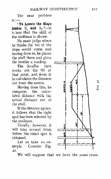
RAILWAY CONSTRUCTI"}~.y 117
The next problem is :-
, To Locate the Slo}le Stakes Sl and S2.'-It is here that the skill of the staffman is shown.
He must judge where he thinks the toe of the slope would come, and having done so, he places the staff there and gives the leveller a reading.
The leveller then works out the fill at that point, and from it he calculates the distance out from the centre.
Having done this, he compares the calculated distance with the actual distance out of the staff.
If the distance agrees, it follows that the right spot has been selected by the staffman.
Usually, however, it will take several trials before the exact spot is obtained.
Let us take an ex-ample. Consider Fig. 42 .
We will suppose that we have the same cross-
1I8 FIEL~ E"NGINEER'S HANDBOOK
~t~ti,~n .8.~ i~ t h~ Jast ,figqre" sp that the grade staff 153":Z'" '" '.' . ." ,
, : £;i: us. sUl?po~e . ~~!lt :the' 'st~ffman is trying to locate the?oin'!: 2: ,..
Supp'ose lie 'guess-es: at'- point 1 first. The staff reading would be 12',
Therefore the fill = la' Therefore the distance out = IO + 5 + 7"5
= 22'S'
But his actual distance out is I9" Since this does not correspond with the proper
distance out for a fill of IO', let us suppose he makes another guess at point 3,
Here, the staff reading would be 13'6',
Therefore the fill = II'6'
Therefore the distance out = II'6 + 5'8 + 7"5 = 24'9'
But his actual distance out is 26'; hence he would try again at point 2,
This time the staff would give a reading of 12'8',
Therefore the fill = 10'8'
Therefore the distance out = IO'8 + 5'4 + 7"5 = 23'7',
This agrees with his actual distance from the centre line, and hence he would drive a stake and mark on it the distance out- 23'7,
The process would, of cours~, be repeated for the right side; and the notes of the cross-section would be entered as follows:
- IO'8
23'7 -6'0
16'5

RAILWAY CONSTRUCTION 119
It ",,"ill be seen that the process of cross-sectioning is one of trial and error.
With regard to the number of cross-sections that it is necessary to take, if the ground slopes evenly between two stations, one cross-section at each station is sufficient; but if there is a sag or elevation between the stations, cross-sections must be taken at the lowest part of the sag or on top of the elevation.
For instance, let Fig. 43 represent a profile of the line between two stations.
--r--11-TT---r I I I I I I I I 1 ~I 1-
A c~ _ F e o
FIG. 43
Let the dotted line represent the grade line. Then in order to estimate the contents of the embankment between A and B, it will be necessary to take cross-sections at A, C, D, E, F, B; that is to say, at every point where there is a distinct change in the slope of the ground.
Of course it is not necessary to leave slope stakes at all these cross-sections, but merely to take crosssection notes for calculating purposes.
In this way, the whole railway is carefully crosssectioned.
Grade Plugs.-Wherever an embankment comes to an end and a cut commences, or vice versci, it is necessary to leave actual grade plugs showing exactly where the formation changes from a cut to a fill,

120 FIELD ENGINEER'S HANDBOOK
Such points will, of course, be determined when the actual staff reading is the same as the grade staff,
Similarly in side hill work, such as in Fig, 44, a grade plug would be placed at P; simply a wooden peg driven flush and to the elevation of the grade,
Cross-sectioning is an art in itself, and can only be acquired by actual practice,
Form of Cross-sectioning Book (Fig, 4S},-A Cross-section Book is kept just like a Level Book; but in addition to the level notes, cross-section notes
FIG,44
of embankment and excavation are kept on the righthand side of the page,
In the first line a backsight is taken on B.M, whose elevation was 2240'68, and by addition we get the H,I. 2243'32,
The elevation of the grade at station a + 00 is taken as 2240'00,
Hence the grade staff is 2243'32 - 2240 = 3'32', The staff when held at station 0 + 00 read 3'32,
thus giving a point of neither cut nor fill, that is, a grade point.
The gradient is taken as 0'5 foot per station, up hill. Hence the grade staff will decrease 0'5 foot at every station,

RAILWAY CONSTRUCTION 121
At station 1 the grade staff is 2'82; the actual staff readings at the left, centre and right of the line were 4'0, 3'5, 2'82, thus giving embankments of - 1'2
and - 0'7 on the left and centre, but a grade point on the right.
Grade is always taken at 10 feet out, on account of the width of cuts being 20 feet.
The notes proceed in the same way until we reach a turning point.
This gives a new H.I., and consequently a new grade staff.
The great point to remember is that the grade staff decreases for up-grades, and increases for downgrades.
In cases where we obtain a negative grade staff, such as when the embankment is higher than the H.I., the grade staff reading is added instead of subtracted.
After all the cross-section stakes have been placed in the ground the contractor usually replaces the small stakes with more substantial ones. At the same time contractors have been known to place their stakes closer in than the original ones.
Vertical Curves.-Vertical curves are placed at all changes of grade where the algebraic difference exceeds 0'2 feet. Every railway has its own particular method of calculating the elevations of the grade on vertical curves.
The method about to be described is very simple and is applicable to aU vertical curves, whether they are at sags or summits, and no matter what length they may be.
Vertical curves are much longer in sags than on
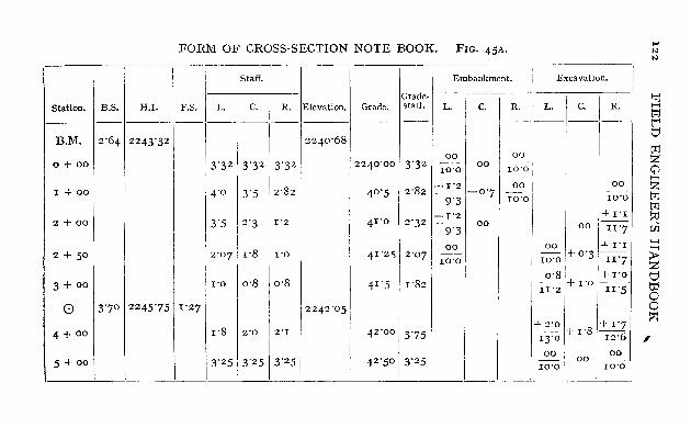
FORM OF CROSS-SECTION NOTE BOOK. FIG, 45A,
Staff, Embankment, Excavation.
Station, B.S, H,I. F,S, L.1c.iR. Elevation, Grade, Grade' 1 I 1 I staff, L. 1 c, I R, L. i c, R, _
-I---~·~~~
B,M, 2'64 2243'32 I: 2240'68
0+ 00 I 13'3213'32 3'32 12240'001 3'32 00
10'0
--~I-I~-
00 00
10'0
00
I
I 1 + 00
2 + 00
1
2 + 50
3 + 00
o 13'70 12245'751 1'27
4'0 13'5 12'82
3'5 2'3
2'07 r'8
1'0 0'8
1'2
1'0
0'8
40'5 1 2'82
41'0 12'32
4 1 '2112'07
41'5 1 1'82
2242'05
-1'2 ~1-O'7 10'0
-1'21 -9-3-1 00
00 ' ro'o
1 00 1 10'0
:+ r'I
00 ' II'7
00 I 1+ 1'1 ro'o + 0'3 II'7
0'81 1+ 1'0
m +I'OIII-S
... N N
!'Ij J-<
t:rJ
b t:rJ Z o H
Z t:rJ t:rJ ~ Ui ~
~ I;j to o o ::-i
4 + 00 1'8 12'0 12'1 42'001 3'75 +2'01 '+1'7 i3:O + 1'8 I-I2~ I ,
00 I 00 3'25 i 3'25 1 3'25 5 + 00 42'50 I 3'25 __ 00 --10'0 10'0 -------- --

Station,
FORM OF CROSS-SECTION QUANTITY SHEET, FIG, 45B,
Grade Elevation. Left; c, Right;
Area;
Emb, Exc,
Volume Cubic yards.
Emb, Exc,
~--1~0~1 1- 00-1 0+ 00 224°'00 - - I 0'0 I ~ 0'00 10'0 10'0
---- ~-;'-2--- -I 00 I -I 14"4 1 + 00 40'50 -- I -0'7 T75 0'00,
9'3 10'0 I ________ ~ ____ ---- I 22'7 6'8
-1'2 +1'1 II 2 + 00 41'00 I 0'0 ,-- 4'50 5'50
9'3 II"] ----I 2'8 II"]
2 + 50 I 41"2 5 ~ 0'0 I +0'3 +_1_'1 1 0'00 1 TI7 I--~--I W'O I II '7 I
-3-+-0-0-1-4-1-'5~-I_+0_'8 \ +1'0 +1'0 1"---1 20'35 1_ .. :5
'5
II'2 II'5 I II4'6
+2'0 I +1'8 +1'7 I I 41"54 ~ 13'0 ,12'6 I
----' 76 '9
00 1 00 1 42'50 10'0 0'0 10'0 0'00 . ·-----1
-----
4+ 00
5+ 00
42 '00
T10tal Cubic I Yardage 39'9 I 235'5
~ :;... H
~ () o z (fJ
>-:l ~ c:: q H o Z
... N
W

124 FIELD ENGINEER'S HANDBOOK
w > (t g oro\;1; (f)
::> u .J ~
oreal; t '0 z u 0 ~
l- v n: ILl 01'0
> Z 0 ({) eG' a
Z 0 l-e(
> IJ .J '~ ro ILl 1/1 Ol'sa.:
'10 \ <t 6l III O\'VZ£
'0 « 0 9 01'11>£ 10 or€z

RAILWAY CONSTRUCTION 125
summits; but it is usual to keep to one standard length for each.
In the case about to be worked out, a general case has been taken. Consider Fig. 46.
Let the down-grade of r % intersect with the up-grade of 0'6 %.
The algebraic difference = rH. Suppose it is required to place a vertical curve
between these grades, having a length of ten stations, that is, 1000 feet.
Produce either grade as shown in the figure. Then calculate the ordinate AB. All the other ordinates, from the r % grade line
to the vertical curve, are made fractions of AB.
To find AB:-
AB = algebraic difference between the grades X the length of curve in stations
2
Now the length of curve = ro Algebraic difference of grades = r'6
ro Therefore AB = r6 X - = 8'
To Find the Remaining Ordinates :Each Ordinate is a fraction of AB.
2
The common denominator for each ordinate is given by--
(Length of Curve in stations)2 = roz (in this case) = roo.
The numerator for any orrlinate is the square of the number of stations from the P.e. at which that ordinate is situated
126 FIELD ENGINEER'S HANDBOOK
EXAMPLE
To Find Ordinate 4.
Ordinate 4 will be 42 of AB = ~ X 8 = 1'28' 102 100
Therefore-elevation of vertical curve at 4 = 329'10 + 1'28
= 330 '38'
To Find Ordinate 7.
Ordinate 7 will be L of AB = ±~ X 8 = 3'92' 102 100
Therefore-elevation of vertical curve at 7 = 326'10 + 3'92
= 330 '02
Should it be required to find the ordinate of any point between two stations, consider the plus as a decimal of a station, For instance,-
To Find the Ordinate at 6 + 50 from the P.C.-
6'52 42'25 Ordinate will be - of AB = -- X 8 = 3'38' r02 roo
Therefore-elevation of curve at 6 + 50 = 326'60 + 3'38
= 329'g8 (same as at station 6).
Calculation of Earthwork -Having completed the cross-sectioning of the residencies, the next thing to be done is to calculate the amount of excavation and embankment. rn
The method of calculation about to be described
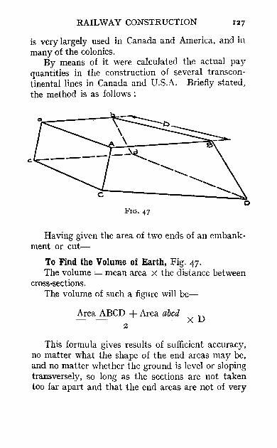
RAILWAY CONSTRUCTION 127
is very largely used in Canada and America, and in many of the colonies.
By means of it were calculated the actual pay quantities in the construction of several transcontinental lines in Canada and U.S.A. Briefly stated, the method is as follows:
c:
FIG. 47
Having given the area of two ends of an embankment or cut-
To Find the Volume of Earth, Fig. 47. The volume = mean area X the distance between
cross-sections. The volume of such a figure will be-
Area ABCD + Area abed X D z
This formula gives results of sufficient accuracy, no matter what the shape of the end areas may be, and no matter whether the ground is level or sloping transversely, so long as the sections are not taken too far apart and that the end areas are not of very
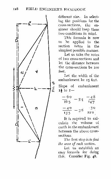
128 FIELD ENGINEER'S HANDBOOK
different size. In selecting the positions for the cross-sections, the engineer should keep these two conditions in mind.
This formula is now to be applied to the section notes in the simplest possible manner.
Let us take the notes of two cross-sections and let the distance between the cross-sections be 100 feet.
Let the width of the embankment be 15 feet.
00 -.r ci Slope of embankment ~ I! to 1-
- 6·0 -4.8 16·5
-5·4 14·7
-4.0 -3.8
-3·0 13·5 12·0 :
It is required to calculate the volume of earth in the embankment between the above crosssections.
The first step is to find the area of each section.
Let us establish an easy formula for doing this. Consider Fig. 48.
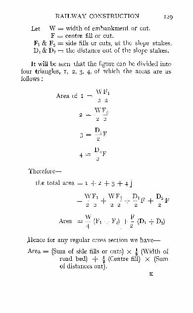
RAILWAY CONSTRUCTION 129
Let W = width of embankment or cut. F = centre fill or cut.
Fl & F2 = side fills or cuts, at the slope stakes. Dl & D~ = the distance out of the slope stakes.
It will be seen that the figure can be divided into four triangles, I, 2, 3, 4, of which the areas are as follows:
WF1 Area of I =
Therefore-
2 2
WF., 2 = ----"
2 2
3 = DIF 2
the total area = I + 2 + 3 + 4 J
= 'YF1 + WF2 + ~lF + D2F 22 22 2 2
;Hence for any regular cross section we have
Area = (Sum of side fills or cuts) X ! (Width of road bed) + ! (Centre fill) X (Sum of distances out).
K
130 FIELD ENGINEER'S HANDBOOK
In our case we have
-6'0 - 4'8 (r) 16'5
-5'4 14'7
- 4'0 - 3'8
- 3'0 (2)
13'5 12'0
Area of I = (6'0 + 4'8) X IS + 5'4 X (16'5 + 14'7) 4 2
= 124'74 square feet.
IS 3'8 Area of 2 = (4'0 + 3'0) X - + ~ X (13'5 + 12'0)
4 2
= 74'70 square feet,
Hence we can find the volume in cubic yards,
Volume = 124'74 + 74'70 X 100 = 9972 cubicfeet. 2
Dividing by 27, we get 369'3 cubic yards,
In this way the area of every cross-section is worked out and checked over by two or three people,
The volumes are then calculated and checked, These calculations are usually given to the chainman and the axeman to do,
Calculation of Volumes, - In calculating the volumes we have three cases to consider.
Case 1. Where there are two end areas. Case 2, \Vhere one end tapers away to a line, Case 3, 'Where one end tapers away to a point,

RAILWAY CONSTRUCTION 131
Case r, Consider Fig, 49,
-6'0
r6'5
FIG, 49
-5'4 -4'8 r4'7
-4~ -3~ -3'8 13'5 2'IO
V I Sum of areas D oume = X 2
Case 2, Consider Fig, 50,
00
ro'o
FIG,50
00
-5'4
00
ro'o
-4'8 -6'0
r6'5 r47
Volume = Area of end X ~) 2
K2

132 FIELD ENGINEER'S HANDBOOK
Case 3, Consider Fig, 5I.
FIG, 51
00 + 1'6 + 1'8
10'0 IZ'7
- 6,0 -4'8 16-S - 5'4
147
Volume of Embankment = Area of end X ~ '3
Profile of Residency.-It has been ~the authors' experience to find that the profiles supplied from headquarters are very often inaccurate, especially when they have been obtained ""ith the Tacheometer.
An accurate profile of the residency should be made as soon as possible, on which should be marked the cubic contents of each cut or fill, the amounts being taken from the cross-section notes.
This profile should be made on hard profile paper, ruled as follows:
Vertical scale: I" = zo', Horizontal scale: I" = zoo'.
Progress Proftle.-As the work of construction proceeds the amount of earth moved is estimated and denoted on the profile by means of painting in the

RAILWAY CONSTRUCTION 133
portion of work done. The earth moved in each month is distinguished by means of keeping a special colour for each month of the year.
Direction of Haul.-Every profile of a railway is made up of alternate cuts and fills. In placing the grade lines upon the profile, an attempt is made to equalise the amount of embankment and excavation.
If the excavation exceeds the embankment, it will be necessary to waste or spoil the surplus.
Generally speaking, vyasting or spoiling excavation is bad engineering and must be guarded against.
Usually, however, the embankment will be in excess of the excavation; and in that case the balance must be made up by means of Borrow Pits or Side Cutting.
It will occur to the reader that the question will often arise as to which of two directions shall be chosen for hauling the earth from a cut.
Overhaul.--It is always arranged with the contractor that all excavated material shall be hauled a certain distance free of charge, called the 'Free Haul.' This distance varies from IOO to 2000 feet; a fair average is 500. If any earth has to be hauled farther than the limit of free haul, then , Overhaul' is charged at so much per cubic yard.
Frequently the direction of haul will be obvious on looking at the profile; but just as frequently, skill is required to determine the most economical direction of haul.
Contractors will be frequently asking the engineer for instructions as to where excavated material is to be placed. Wherever it is possible to do so half

134 FIELD ENGINEER'S HANDBOOK
the earth from an excavation should be hauled in one direction and the other half in the opposite direction. Consider Fig. 52.
Let this represent an isolated cut, with a filI on both sides.
FIG. 52
Obviously the most sensible way to excavate this will be as shown in the figure.
Now consider Fig. 53. In this case the direction of haul for the various
cuts is not so obvious, especially when one is actually on the ground.
-.------.50o'-----~
FIG. 53
A moment's consideration will show that the' most reasonable direction for moving the earth IS
as indicated by the arrows. Supposing, however, that the earth from A
and B was hauled in the opposite direction into P and Q.
The result would be that the earth from the large

RAILWAY CONSTRUCTION 135
r-----r---.------..-~--------------_,Q
"" OJ")
t------+--~--------~~_4--------------~O . tt> ~ ~
t------+---~------~~;_--------------~O <t
~ __ -L~~ ________ ~ __________ ~g

136 FIELD EKGTi-TEER'S H/\NDBOOK
cut C would have to be hauled all the way to F and to G.
Let the free haul be 500 feet. Then we see that the contractor would charge overhaul for every cubic yard taken from C and deposited in F or G.
The distance hauled is taken as the distance between the mass centres of the fill and the cut from which the earth came.
Haul Diagram.-The most accurate way of determining the direction of haul is to draw what is called a Haul Diagram for any section of the profile about which there is any doubt. Consider Fig. 54.
To Draw a Haul Diagram.-Choose any grade point on the profile such as the point A.
Commence plotting the quantity of earth per station, as given by the cross-section notes, taking due regard for the sign of the quantities. That is to say, plot embankments downwards and excavations upwards, or vice versa.
In this way a curve will be obtained which will be divided into portions alternatively cut and fill.
Horizontal lines can now be drawn as shown in the figure.
These lines determine the distance, the direction of haul, and the overhaul.
In the last figure it will be seen that the cut PQ and the little piece of cut at X will all have to be hauled farther than the free haul limit.
At B we see that no more excavation is available to make the embankment, hence a Borrow Pit must be commenced at that point and the embankment completed with borrowed earth.

RAIL\,\'AY CONSTRUCTION 137
The method of computing overhaul is a graphical one. Consider Fig. 55.
Let Fig. 55 represent a portion of a haul diagram. The vertical scale is 200 cubic yards to one inch. The horizontal scale is 200 feet to one inch. Let the freehaullimit be 500 feet. Slide a scale down horizontally between the two
sides of the haul curve, and rule horizontal lines
765432 A
FIG. 55
denoting distances from 500 feet upwards. Then, for such a diagram, the quantities vvould be as follows:
200 cubic yards hauled free of charge. 70 100 feet overhaul 70 200 "
70 3 0 0 "
140 400
130 " "500,, " Such a diagram must be drawn for every cutting
in which there is likely to be any overha.ul charged.

I38 FIELD ENGINEER'S HANDBOOK
Borrow Pits: Side Cutting. -- These should be staked out by the engineer and cross-sectioned before any excavation is allowed. The contractor should be made to keep the pits neat and regular, and to make the pits self-draining. This is a very important thing in tropical countries where it is of vital importance to prevent the accumulation of water in pools for the benefit of mosquitos. Never allow a borrow pit to be commenced at the mouth of a cut for obvious reasons.
Culverts.-Wherever an embankment is likely to obstruct the flow of water in rainy weather a culvert should be built.
This is merely some kind of contrivance for allovying water to pass from one side of an embankment to the other. Culverts are of very varied types, ranging from ordinary drain-pipes to large arched culverts.
Reinforced concrete culverts are common; but in America the ordinary wooden box culvert is largely used.
Whenever possible, culverts should be constructed before embankments. Hence the position for the foundations of all culverts should be staked out at the same time as the cross-sectioning is performed.
Wherever possible, culverts should be placed at right angles to the line, and should be given such a slope that will make them self-draining.
Road Crossings.-Wherever the line cuts a government road allowance, a road crossing will have to be constructed. The road will be built in exactly the same way as the raihvay, and with the same material.

RAILWAY CONSTRUCTIO~ 139
It must be staked out and cross-sectioned in the same manner. The actual width of the road will always be given to the engineer.
Farm Cl'ossings.-When the line passes through a farm, it is the custom to build a small road crossing for the farmer. The crossing will be chosen at a grade point, to minimise the amount of construction, and at the higher end of cuts so as not to obstruct drainage through them.
Cut Ditches.-Ditches are dug along the sides of all cuts, to facilitate drainage; the earth from the ditches should be placed in the embankment.
Shl'inkage.-Earth embankments shrink considerably after being newly made. The amount of shrinkage depends, of course, on the material used in making the embankment.
Hence the contractor must be made to build the bank higher than the calculated height of grade, to allow for this shrinkage.
The amount of shrinkage determined \V·ill be a percentage of the height of the embankment; and will usually be decided upon by the assistant engineer in charge of the whole line.
Second Grades.-When nearing the completion of an embankment or cut, the contractor will ask for ' Second Grades.' The placing of second grades merely consists in driving wooden pegs into the embankment at right angles to the line, at every station, and at the proper distance apart, namely, fIfteen feet in a fill and twenty feet in a cut. The tops of the pegs are hammered down so that they are at the proper elevation plus the shrinkage. The
140 FIELD ENGINEER'S HANDBOOK
contractor will then build the embankment until level with the tops of the second grade stakes.
Finishing Stakes or Final Grades.-When the work is practically complete, finishing stakes must be driven into the embankment to enable the contractor to trim u'P his work and leave it ready for ballasting.
Finishing stakes should be long, substantial wooden stakes, hammered down to grade on each edge of the road bed at every station; the stakes being set at half the width of the road bed from each centre stake.
The contractor should be made to stretch a line between the stakes from station to station; and the embankment should be well filled out to the full width between stations.
The tops of the stakes are usually marked with blue chalk so that they can easily be seen.
Before allovving the contractor to leave his work and before giving him his estimate of the work he has done, the engineer should check the elevation of grade, over the embankments and through the cuts.
'\Then this is done, the work is complete and ready for Ballast, and Track Laying.
No attempt is made in this book to enter, into the subject of Track Laying.

CHAPTER X
TACHEOlVIETRY
TACHEO!lIETRY, as its name implies, is a sy:.tem of rapid measurement. It enables a surveyor to perform the field-work usually carried out by the use of a theodolite, chain, level and staff with a single instrument .. the Tacheometer, and a specially gradu· ated staff.
The accuracy and precision of good tacheometry is rarely fully appreciated.
With proper care to eliminate the chief sources of error, a high degree of accuracy may be obtained. In rough country where the slope of the ground seriously affects the accuracy of chaining, the tacheometer produces results as good as those with a chain.
It has been found as a result of a series of tests that the limit of accurate tacheometric measurement is about 800 feet.
With the tacheometer, the distance of any point and its elevation can be obtained at one operation. The principle of obtaining distance by tacheometry can be shown by the following simple illustration. Suppose a match, one inch long, be held vertically, and one foot from the eye. Suppose also that a graduated staff be held some distance away and

142 FIELD ENGINEER'S HANDBOOK
that the match appears to cover up three feet of the staff. Then we know that the staff must be 36 feet away.
The Tacheometric Theodolite.
Consider Fig. 56. Let a, b, and c represent three horizontal hairs
in the diaphragm of a telescope, and let c and a be eqlli-distant from b. Of all the rays of light which
I f+-,-k-4-F--.J f------D-- __
FIG. 56
emerge from each of these let us consider three which are parallel to the axis of the telescope as shown in the figure. These, on striking the object-glass, will converge to the principal focns and pass on as shown. Let them strike a staff in the three points A, B, and C, which are at distances rs' r2, and J\ from the foot of the rod. Let k be the distance from the object-glass to the trunnion axis, and let f be the focal length of the lens; these are fixed quantities for a telescope. Let D be the distance of the staff from the trunnion axis: this distance is to be found.
Let length ac = i.

TACHEOMETRY
From similar triangles
D - f - k _ r3 - rl f -~i-
.'. D=f(r3- rl)+f+ k ~
In this expression f is called the 'multiplying ~ .
constant,' and is usually made by the makers to be
roo or some round number (sometimes j is called
the' multiplying constant '), and f + k is called the , additive constant,' and is either given by the makers or can be measured (it is usually about J ~ feet).
To determine f and k.-Focus on a distant object so that the rays that strike the lens may be parallel, and measure the distance from the object-glass to the trunnion axis (k) and from the object-glass to the cross-hairs, which is equal to J.
Inclined Sights.--So far we have assumed the line of sight to be horizontal. In most cases it will not be so. Even if it is not horizontal, the staff must be held truly vertical with the help of a disclevel or of a plumb-bob.
Consider Fig. 57. Let e be the angle of elevation of the telescope. As before, from similar triangles-
L - f - k (r'1 - 1'1) cos e .. f = i (for all practlcal purposes)
'. L =-0 ~ (1"1 - 1'1) cos e -+ J -1- h ~
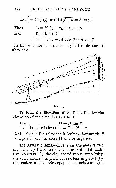
144 FIELD ENGINEER'S HANDBOOK
Let { = 1\1: (say), and let f + ii = A (say).
Then L = 1\1: (rs - rl) cos () + A
and D = L cos ()
.. D = lVI (r:l - rl) cos2 () + A cos ()
In this way, for an inclined sight, the distance is obtained.
FIG. 57
To Find the Elevation of the Point P.-Let the elevation of the trunnion axis be T.
Then H = D tan () .'. Required elevation = T + H - r2
Notice that if the telescope is looking downwards () is negative, and therefore H will be negative.
The AnaBatic Lens.--This is an ingenious device invented by Porro for doing away with the additive constant A, thereby considerably simplifying the calculations. A plano-convex lens is placed (by the maker of the telescope) at a particular spot

TACHEOMETRY
between the cross-hairs and the trunnion axis in such a position that its principal focus falls between the trunnion axis and the object-glass.
Consider Fig. 58. The anallatic lens is fixed by the instrument maker in such a position that the rays of light passing through it and out of the object-glass are refracted in such directions that when produced backwards they intersect at the trunnion axis.
I I
H----D--
FIG. 58
The formula for the distance of the staff is now very much simplified. We have-
Hence
tan § = rg - r1
z zD
.'. D - __ 1 ---OOfJ (rs - rl)
2 tan -2
D = K (rs - rl)
for horizontal sights, and for inclined sights we have as before-
D = K (rs - r 1) cos2 0
Suppose a common staff is used, then we shall have to multiply the intercept on the staff (viz. '·s - r1) by a constant such as 100, and by cos2 0, to get D.
L

146 FIELD ENGINEER'S HANDBOOK
But if we graduate the staff so that one actual foot is represented by ilith of a foot on the staff, we shall only have to multiply the intercept by cos2 e. Hence, if the maker supplies an instrument and says that the constant is O'OI, we must use a staff such as that just described, and use the formula-
D = (rs - rl) cos2 e (rg - rl is called the' Generating Number ').
In this case the formula for the height H becomes-
H = D tan e or H = (rs - r1) cos2 e tan e To summarise :
D = (rs - rl) cos2 e } H = (rg - rl) cos2 e tan e
Before the elevation of a point can be determined, it is necessary to know the reading of r2' This may be done directly in the field, or in the office by finding the mean of rl and rs. It is evident that with a special staff the value of r2 will have to be multiplied by the constant (viz. O'OI, if that is what is being used).
There are many different staffs in existence, depending upon what units of measurement are adopted. It has been found convenient in some cases to make the yard the unit of measurement and 0'02 the constant, in which case each graduation is 0'72 inch, which makes a good, bold staff. The conversion of yards to feet)s _done in the office.
The modern Tacheometer is merely an ordinary theodolite fitted with an anallatic lens and three horizontal cross-hairs.
TACHEOMETRY Ii7
Field Work.-The survey party should consist of
(1) The engineer-in-charge. (2) The instrumentman. (3) The assistant to the instrumentman. (4) As many staffmen as the instrumentman
can deal with.
Let us suppose that the survey is to be one for a railway, and that it is required to run the traverse, take the levels, and obtain the topography with a tacheometer.
The tacheometer must be set up at the first station, and the height of its trunnion axis be found. If there is a bench mark close by, this may be found by a tacheometer measurement on the bench mark; but if the nearest bench mark is far away, the height of the trunnion axis should be found by means of levelling with an ordinary level from it.
The next operation is to range out the first course of the traverse. This is done exactly as described in former chapters, and the bearing of the first course is found astronomically or otherwise.
The engineer-in-charge now directs the staffmen to various points around the instrument, and the instrumentman takes tacheometric readings r1 and r3 on the various staffs.
It is convenient to elevate the telescope so that r1
is a round number, so that r3 - rl is easily calculated: r~ may be taken as the mean of rl and r3' In addition to these readings, the angle of elevation or depression of the telescope and the bearing of each line of sight must be noted.
All the readings are taken down by the assistant to the instrumentman, thus enabling the latter to
L2
148 FIELD ENGINEER'S HANDBOOK
give his whole attention to the manipulation of his instrument.
When all the readings within the range of the tacheometer have been taken, the instrumentman sets a hub on line and takes readings to determine its distance away and its elevation before moving the instrument.
The tacheometer is now moved on to the new point and set up. The instrumentman measures the height of the trunnion axis above the point, thus obtaining the new height of his instrument.
He then takes a backsight on to the first instrument station, and takes readings to determine its distance away and its elevation.
If these check with the previous determinations, he proceeds to repeat the operations previously described, taking tacheometric readings in all directions within the range of his instrument.
In this way he proceeds until the end of the first course is reached, when he ranges out a new course, and takes his tacheometric readings as before.
Office Work.-The first work in the office is the reduction of the field-book.
A sample field-book is given in Fig. 59 to show how the calculations are performed.
The exact form of field-book depends entirely upon the nature of the survey and the fancy of the engineer-in-charge. For this field-book, tables of cos2 e and of cos2 e tan e (i.e. sin e cos e) are required.
In reducing Tacheometric observations, the reader will use either some such tables as these or a diagram. There are many systems in use.
The traverse is plotted in the usual way by
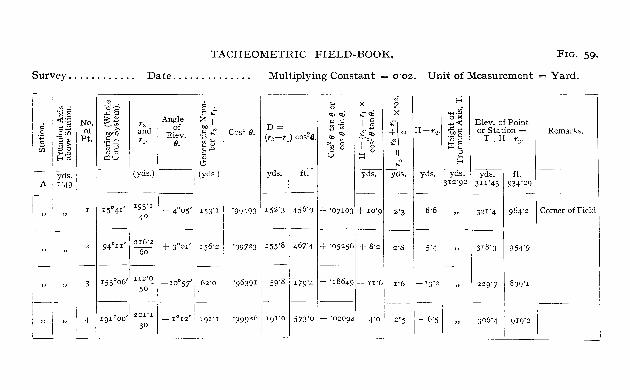
TACHEOMETRIC FIELD-BOOK. FIG, 59.
Survey, , , , , , , , , , " Date""""""" Multiplying Constant = 0'02, Unit of Measurement = Yard,
"' ... 1~3 No, a 011 of
~ I'~~ Pt, U) 82
f-<r.>
-- IYdS'I A I'49,
I "
.a--="''' :;;:2 -~
.§~ ,,'-' ~.!::
Q:lU
1'::1 and 'I'
___ j(YdS.)
15°41' I 193'I 40
Angle of
Elev, 0,
+ 4°05'
~ ~ Z .. ",,' " ~ '.jj~ oJ ... ... '" ~.o
'" I (yds.) :
Ij3"I
94°II ' 1216'2 I + 3"01' 1 156'2
60
-3-1' 153006,1~I2'O . - I0057' -:::-50 .
i--I 1
i " 1 I
--- ------ ---
191°00' 221"1 _ 1°12' 191"1
30
C052 6. D= (r3-r,) c05"8.
1:i "".; " " .s '(il
",,""
~. '8 ~ (,)
U
x ~q; , ;; £G~
II ~ . iIi '-'
N ? X
~\ N H-r1.11
II .:: I
"H'~" 0" ~< -§,o ._ 0
:!l'g " ?::
yds, ft, yds, Iyds, I yds, lyas.-312 '9 2
'99493 I 15 2 '31456'91+ '07I031+ IO'91 2'3 I 8'6
--'-"-1-'9972 3 I ISS'S i 467'41 + '05256, + S'2 2'S 1 5'4
2'5 1- 6'51
- 1--'963911 59'S 179'41- '186491- II'6
'999'" 1 IgI'O 1573'0 1- '02094"~-:: I
I'6 1-13'2
Elev, of Point or Station = T+H-r1 ,
~ ft, 3II '43 934'29
32 I' 4 964'2
3, S'3
22g'7
306'4
954'9
899'1
9I9'2
Remarks.
Corner of Field 1
150 FIELD ENGINEER'S HANDBOOK
latitudes and departures, and all the staff-points upon which spot-levels were taken are marked on the plan with their elevations. This is done with a scale and protractor, the latter being as large as is convenient to use, and very carefully graduated.
The contours are interpolated from these spotlevels and are carefully drawn in.
Longitudinal or cross sections can be projected very easily from the contours.
The authors have mentioned before that only the general principles of Tacheometry are here explained, because there are so many different methods of carrying out the work, each of which is considered the best by the engineer practising it.
CHAPTER XI
ASTRO~OMY
RELATIVE MOTION OF THE EARTH, SUN, AND STARS
THE astronomy given here is sufficient to enable a surveyor to find latitude, longitude, and bearing (or azimuth as it is called in astronomy) from the sun or stars. In most cases the latitude and longitude of a place are only required for the purpose of finding azimuth.
It is assumed that the reader lmows the ordinary theory of the motion of the earth round the sun. Since all motion is only relative, we are quite at liberty to consider the earth as the centre of the universe, with the sun moving round it. It may be said at once that the earth and sun are quite near together (being only ninety millions of miles apart), but that both are infinitely distant from the stars. In the diagrams that follow, the sun is drawn among the stars; this is because we, on the earth, s~em to see it infinitely far away.
In astronomy angles are sometimes expressed in degrees, minutes, and seconds, but often in hours, minutes, and seconds. If we imagine 3600 to be equal to 24 hours, then any fraction of 3600 is the same fraction of 24 hours: thus an angle of 60°
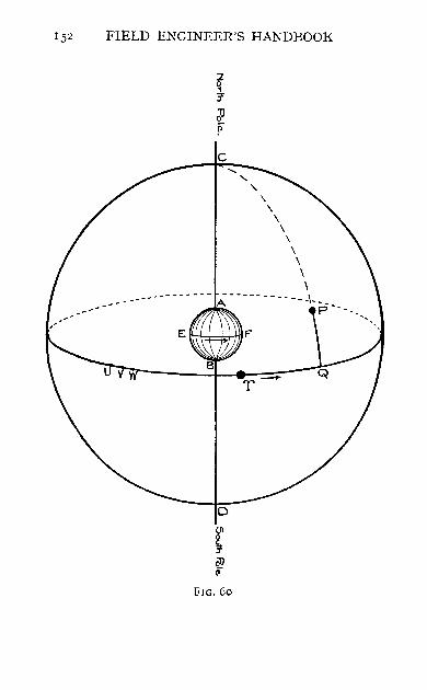
152 FIELD ENGINEER'S HANDBOOK
o (J'l
~ 29 '"
FIG. 60
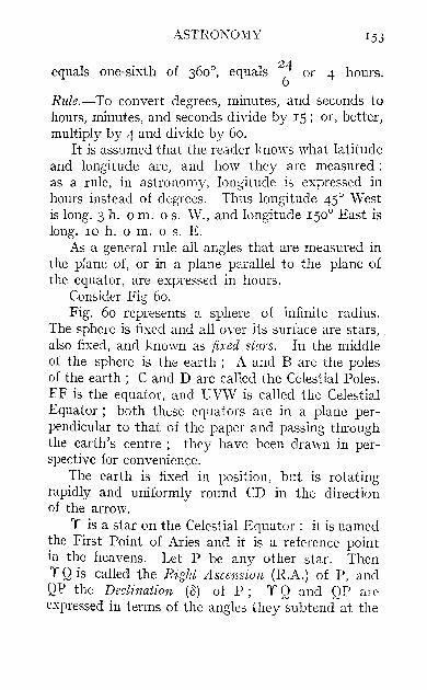
ASTRONOMY 153
equals one-sixth of 360°, equals 24 or 4 hours. 6
Rule.-To convert degrees, minutes, and seconds to hours, minutes, and seconds divide by IS; or, better, multiply by 4 and divide by 60.
It is assumed that the reader knows what latitude and longitude are, and how they are measured: as a rule, in astronomy, longitude is expressed in hours instead of degrees. Thus longitude 45° West is long. 3 h. 0 m. 0 s. W., and longitude 150° East is long. 10 h. 0 m. 0 s. E.
As a general rule all angles that are measured in the plane of, or in a plane parallel to the plane of the equator, are expressed in hours.
Consider Fig 60. Fig. 60 represents a sphere of infinite radius.
The sphere is fixed and all-over its surface are stars, _ also fixed, and known as fixed stars. In the middle of the sphere is the earth; A and B are the poles of the earth; C and D are called the Celestial Poles. EF is the equator, and UVW is called the Cele&tial Equator; both these equators are in a plane perpendicular to that of the paper and passing through the earth's centre; they have been drawn in perspective for convenience.
The earth is fixed in position, but is rotating rapidly and uniformly round CD in the direction of the arrow.
'f is a star on the Celestial Equator: it is named the First Point of Aries and it is a reference point in the heavens. Let P be any other star. Then 'f Q is called the Rigltt Ascension (R.A.) of P, and QP. the Declination (0) of P; Y Q and QP arc expressed in terms of the angles they subtend at the

154 FIELD ENGINEER'S HANDBOOK
centre of the sphere; in the figure the Right Ascension of P is about 30° 0' 0", or 2 h. 0 m. 0 s., and the Declination of P is about 20° 0' 0".
The RA. and () of any fixed star are constant, or practically constant, and are given in the Nautical Almanac (abbreviationN.A,). The Nautical Almanac is briefly described on page 163. .
A Mean Solar Year is the time taken bv the earth to complete 366'2422 revolutions about it; axis.
Imagine an object, which we will call the Mean Sun, which starts from Y and moves at constant speed round the Celestial Equator very slowly in the direction of the arrow, and gets back again to 'f at the end of a mean solar year. It is evident that any meridian or the plane of any meridian of the earth, while transiting (or crossing) 'f 366'2422 times in a year, transits the mean sun only 365'2422 times, Hence the mean sun appears to cross any mpridian of the earth 365'2422 times in a mean solar year, producing 365'2422 days. A common clock is a machine which records these days; whenever the mpridian of a place crosses the mean sun, the common clock strikes twelve, and we say that it is noon. It is evident that common clocks in different meridians register different times at the same moment; sinee the earth turns exadly once on its axis relative to the sun in the direction of the arrow in a day or 24 hours, it is obvious that a common clock in longitude 3h. om. os. \V. is 3 h. om. os. slow of a common clock at Greenwich, and a common clock in longitude loh. om. os. E. is loh. om. os. fast of a common clock at Greenwich, This is important, as all times have to be reduced to Greenwich time, as the N,A. has been compiled for Greenwich time.
ASTRONOMY ISS
In astronomy, however, times on the common clock have to be reduced to times on an astronomical clock: the .Tatter keeps exactly the same time as a common or mean time clock, but it has a dial divided into 24 hours instead of I2 hours, and o h. 0 m. 0 s. on the astronomical clock represents noon. Common and astronomical clocks both keep 'mean time' as it is called.
Rule for Converting Times on a Local (Astronomical Clock to Greenwich Mean Time.-If the longitude be west, add the longitude' in hours to the local time. If the sum exceeds 24 hours, deduct 24 hours and add one day to the date.
If the longitude be east, subtract the longitude in hours from the local time. If the result be negative, add 24 hours to it, and subtract aIle day from the date.
EXAMPLE I
Find the Greenwich Mean Time of 4 A.M. March 5 in New York (Long. 73° 57' 30" W.).
h. 111.
4 A.M. March 5 in New York= 16 0 s. o March 4, New
York Mean Time.
Long·=73° 57' 30" W. = +4 55 50
'. Corresponding G.M.T. = 20 55 50 March 4.
EXAMPLE 2
Find the Greenwich Mean Time of 10 P.M. March 8 in Longitude 1650 East.
10 P.M. h. m. s. 10 0 0 March 8, Local
Mean Time. Long. =165° E. = -II 0 0
.', Corresponding G,M,T. ~ - 1 0 0 March 8. 23 0 0 March 7,

156 FIELD ENGINEER'S HANDBOOK
Right Ascension of the Mean Sun.-The Right ascension of the mean sun increases uniformly from zero to 3600 or 24 h. 0 m. 0 s. during one mean solar year. The astronomer's year does not begin on January I, but on March 2I. Therefore, one month after the beginning of this year, namely April 2I, the right ascension of the mean sun is 2 h. 0 m. 0 s. The right ascension is increasing at the rate of 24 h. 0 m. 0 s. in 365.2422 days, or o h. 0 m. 9.856 s. per hour. This increase of right ascension of 9.856 s. per hour is called the' Acceleration' of the mean sun. The right ascension of the mean sun is given for Greenwich mean noon for every day in the year in the Nautical Almanac; in the Almanac, however, it is called 'Sidereal Time 1 at Mean Noon.' It can be found for any other time by applying the acceleraiion for the interval of time since noon occurred.
EXAMPLE 3 Find the R.A. of the Mean Sun at 4 A.M. March 5,
1912, in New York.
From N.A., R.A. of Mean Sun at h. ill. s.
Greenwich Mean Noon, March 4 = 22 47 30.61 From Ex. I, G.M.T. of Observation =20 h. 55 m. 50 s. March 4. m. s.
Acceleration for 20 h. :: 3 17:13}" " " 55 ID. - 9 04 " " 50 s. = . I 4
Increase of R.A. since G.M.N.= 3 26.31 3 26.3 1 ... R.A. at Observation = 22 50 56.92
I The moment when any meridian transits the First Point of Aries is called ' Local Sidere:ll Noon.'
2 From table on page 5H, N.A., 19I2, or from Table V 01 this book.

ASTRONOMY 157
FIG. 61
l5R FIELD ENGINEER'S HANDBOOK
Consider Fig. 61.
Right Ascension of any Mel'idian.-At any moment let CMD be the position of any meridian of the earth. Let CRD be the position of a meridian through a star X.
Now 'Y'R + RM = ,M, ar RA. of any Star + Angle} _ R A f M'd'
of Star West of Meridian - . . 0 en Ian. The angle between any star and any meridian is
called the hour angle 1 of the star (for that meridian). If the star happen to be the mean sun, it is evident that its hour angle expressed in hours, minutes, and seconds is the same as the mean time for the meridian. Hence we may write the important equation:
R.A. of any Star + its Westerly Hour Angle = R.A. of Meridian of Place (sometimes called Local Sidereal Time or L.S.T.) = R.A. of Mean Sun + Mean Time at Place.
EXAMPLE 4
Find the R.A. of the Meridian of New York at 4 A.M.
March 5, 1912, New York time. From Example 3, R.A. of Mean h. m. s.
Sun at observation = 22 50 56'92 Mean Time at Place = 16 0 0
.'. R.A. of Meridian = 38 50 56'92 Subtract 24h. to get an angle less than 3600
.'. RA. of Meridian = 14 50 56'92
EXAMPLE 5 The Star Aldebaran (a Tauri), the R.A. of which is
4 h. 30 m. 52'2 s., was observed at 4 A.M. March 5, 1912, at New York. Find its hour angle.
I Note that this angle is measured in the plane of the equator.

ASTRONOMY 150
From Example 4, R.A. of Meridian h. m. s.
of New York = 14 50 56'92 (Subtract) RA. of Aldebaran = 4 30 52'2
.'. \VesterIy hour angle of Aldebaran = 10 20 4'72
If in this example the right ascension of Aldebaran had been greater than that of the meridian, we should have had to have added 24 h. to that of the meridian to avoid a negative angle.
EXAMPLE 6
The star {3 Hydri, whose R.A. is 0 h. 21 m. 6'0 s., was observed in Long. 30° 0' 0" \V. on April 2, 1912.
If its hour angle was 12 h . .'> m. 10 s., what was the Local Mean Time of the observation?
(I) Find the approximate Local Mean Time. We can say, by slightly altering the equation of page
158, RA. of Mean Sun at G.M.N. April 2 + Approximate Mean Time at Place = RA. of {3 Hydri + hour angle of {3 Hydri . ... Aproximate Mean Time at place
= 0 h. 21 m. 6 s. + 12 h. 5 m. 10 s. - 0 h. 41 m. 51 S.
=II h. 44 m. 25 s.
This is sufficiently accurate for some purposes.
(2) Find the Approximate Greenwich Mean Time. h. m. s.
Approximate Local Mean Time = II 44 25 Longitude West = 2 0 0
Approximate G.M.T. of observation = 13 44 25 April 2.
(3) Find the RA. of Mean Sun for this instant. h. m. s.
RA. of Mean Sun at G.M.N. April 2 = 0 41 50'7 m. s,
Acceleration for 13 h. = 2 8'1 44 m. 7'2
" 25 s. = '1
. 2 15'4 = 2 15'4 .'. R.A. of Mean Sun at observation = 0 44 6'1

160 FIELD ENGINEER'S HANDBOOK
(4) Find the true Local Mean Time. R.A. of Mean Sun at observation + Mean Time at
Place = R.A. of f:3 Hydri + hour angle of f:3 Hydri. .. Mean Time at Place
= 0 h. 21 m. 6 S.+I2 h. 5 m. 10 s.-o h. 44 m. 6·1 s. = II h. 42 m. g.g s.
NOTE.-There is a slightly better way of performing this operation, but it has been thought inexpedient to give it here.
The Apparent Sun.-We have said a great deal about an imaginary body called the mean sun, which starts from a star called Y at March 2I of every year. We have considered this body because the apparent sun (or the sun we see and observe) has a motion very similar to that of this body. The apparent sun is at the star Y on the celestial equator on March 2I of any year, and it pursues a path round the sphere, getting back to Y on March 2I of the next year. It does not, however, move in the plane of the celestial equator, nor is its speed constant.
Consider Fig. 62. In Fig. 62 the apparent sun follows the path PQR.
The moment when the meridian of any place transits the apparent sun is called Apparent Noon, and it differs slightly in time from Mean Noon. The difference between the times of apparent and mean noons is called the Equation of Time. It is given for the moment of every mean and apparent noon in the year in the Nautical Almanac: its hourly rate of variation is also given. Hence it is possible to find the equation of time for the moment of any observation.
Another quantity that is required is the Apparent Declination of the sun at any moment. It can be found in the Nautical Almanac for both mean and
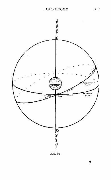
ASTRONOMY 161
FIG.oz
M
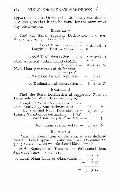
162 FIELD ENGINEER'S HANDBOOK
apparent noons at Greenwich: its hourly variltion is also given, so that it can be found for the moment of any observation.
EXAMPLE 7
Find the Sun's Apparent Declination at 7 P.M.
August 3I, I9I2, in Long. 60° E. h. m.
Local Mean Time = 7 0 Longitude East = 60° = 4 0
s. o August 3I o
.'. G.M.T. of observation = 3 0 0 August 31
N.A. Apparent declination at G.M.N., August 31
N.A. Hourly variation of declination = -54'04"
.'. Variation for 3 h. 0 m. 0 s. =
° I
8 41 32 N.
2 42
.'. Declination at observation = 8 38 50 N.
EXAMPLE 8
Find the Sun's Declination at Apparent Noon in Longitude 60° \V. on December 21, 1912.
Longitude West=60o=4 h. 0 m. 0 s. N.A. Sun's Apparent declination at
G. Apparent Noon, December 21 = 23 27 3 Hourly Variation of declination = + '82"
Variation for 4 h. 0- m. 0 s. = + 3
.'. Declination at observation = 23 27 6
EXAMPLE 9
From an observation of the sun, it was deduced that the Local Apparent Time was 1912, December 21, 3 h. 5 m. IS.: what was the Local Mean Time?
N.A. Equation of Time to be Subtracted from Apparent Time = 1m. 51 s.
h. m, 5,
.'. Local Mean Time of Observation = 3 5 I
I 5I
3 3 IO

ASTRONOMY
(NoTE.-To be strictly accurate the hourly variation applied should be that for a moment half-way between G.M.N. and G.J\I.T. of observation.
Thus in Ex. I ~
at 0 h. 0 m. 0 s. August 3 I, hourly variation = 54 '04" at 0 h. 0 m. 0 s. September I, hourly variation = 54 '38"
The observation was at 3 h. 0 m. 0 s. September I,
so that the hourly variation should be found for I h. 30 m. 0 s. September 1. By interpolation it is found to be 54 '06".
This correction should be applied if the accuracy of the transit warrants it.)
The' Nautical Almanac.'-The information given here refers to the almanac published by the British Admiralty. The almanac is published yearly, and three years in advance. Where the numbers Gf pages are given here, they refer to the I9I2 edition. Between pages 2 and I46 will be found pages devoted to each month of the year. Each month has twelve pages, to which are given the Roman figures I to XII. For this book, only pages I and II of each month are of interest.
Page I has, in all, nine columns, and the page is devoted to particulars of the sun at the moment of Greenwich Apparent Noon of each day. Columns I
and 2 (the date) and 5, 6, 8, and 9 may be of use. Page II has, in all, seven columns, and the page
is devoted to particulars of the sun at the moment of Greenwich Mean Noon of each day. Columns I
and 2 (the date) and 4, 5, 6, and 7 may be of use. Remember, hovvever, that column 7 (Sidereal Time) has in this book been given the name' Right Ascension of the Mean Sun.'
The chief other use of the almanac is to find the right ascensions and declinations of the stars. Though
M 2

164 FIELD ENGINEER'S HANDBOOK
it has been said that these are constant, they do vary slightly, but they can always be found in the almanac under the heading' Apparent Places of Stars' (pages 252 to 4II: pages 233 to 252 are not required). To a beginner, however, it is no easy matter to find a star in this list, so the following may help.
Stars are divided into groups or ' constellations.' Each constellation has a name, such as Orion. The individual stars of the constellation Orion are known as a Orionis, j3 Orionis, 'Y Orionis, etc. The order of the Greek letters is supposed to indicate the relative brightness or ' magnitude.' In this case, the brightest two stars, a and j3 Orionis, are also popularly known at Betelgeuse and Rigel. The stars are tabulated in the order of their right ascensions, so that it is easy to find a star in the list by finding its approximate right ascension either from a star chart or from the list called' Mean Places of Stars' (pages 222 to 232). The table on page 554 may be of use in rapidly finding the' acceleration' of the mean sun during any period: it is practically the same as Table V in this book.
OBSERVATION OF THE SUN AND STARS
In finding Latitude, Longitude, and Azimuth, it is necessary to observe the altitude or angle of elevation above the horizon of the sun or of a star. The observed altitude is not the correct altitude until certain small corrections have been made.
The corrections are as follows:
1. Index Error of Vertical Circle (unless the theodolite is in adjustment for this) .-Suppose the altitude of a celestial body is found to be 30° 40' 20". To correct for index error, sight on some

ASTRONOMY 165
well-defined object and read the vernier: let it read 20° 21' 40". Transit the telescope and resight the object: let the reading now be 20° 20' 20".
Index Error = - ! X I' 20" = - 40"
.'. Altitude of body = 30° 39' 4 0 "
This correction applies to both sun and stars.
2. Refraction.-Refraction is the bending down of the line of sight owing to the unequal density of the layers of air: the correction is always one of subtraction, and its amount is 57" cot a, where a is the approximate altitude. This correction applies to both sun and stars. The correction is very big if the star is on the horizon. If very accurate work is being done, or if observations are being performed in extremes of temperature or barometer pressure, this refraction must be corrected for temperature or pressure from a table in 'Chambers' Tables,' or some other such book.
3. Semi-diameter. -The middle of a celestial body should always be observed. The stars are points of light, so we always observe the centre of them, but the sun is large and it is usual to observe either its upper or lower edge or ' limb.' The correction varies for different times of the year, but it can he found in the Nautical Almanac for any date in column 5 of page II of the month. It is usually about ± 15/, the sign depending upon which limb was observed. It is minus if the upper limb is observed; the upper limb appears at the bottom in an inverting telescope.
4· Parallax.-Since observations taken at different parts of the earth have to be compared

166 FIELD ENGINEER'S HANDBOOK
with Greenwich observations (i.e. with the Nautical Almanac), it is usual to reduce observations to what they would have been if the observer had been at the centre of the earth. The stars are infinitely far away, so that observations of a star do not have to be so reduced; but tbe sun is near, and observations of the sun must be reduced.
Consider Fig. 63 .. P is a point on the eartb. S h is the centre of the sun, when on the horizon.
50(
Sa is the centre of the sun when at altitude a. In the first case the parallax is evidently-
O~_ ~~ooo_~TIil~s __ = 8f sun's distance 9I million miles
This quantity is known as Ph. The parallax when the sun is at Sa is evidently-
OP cos a = Ph COS a
sun's distance :. P a = parallax in altitude = Ph cos a
Ph varies slightly, but 8f' may be taken as its value. It is always to be added.
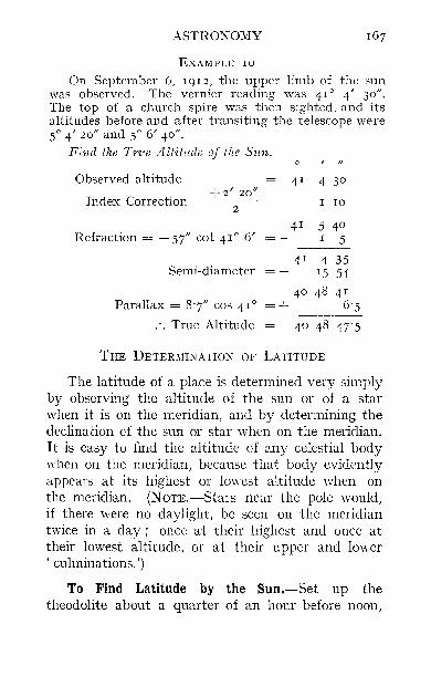
ASTRONOMY
EXAMPLE 10
On September 6, 1912, the upper limb of the sun was observed. The vernier reading was 41° 4' 30". The top of a church spire was then sighted, and its altitudes before and after transiting the telescope were 50 4' 20" and 50 6' 40".
Find the Trve A ltit1tde of the Sun.
Observed altitude 41 4 30 +2' 20"
Index Correction = 2 = + I 10
41 5 40 Hefraction = - 57" cot 41° 6' 5
Semi -diameter 41 4 35
15 54
40
Parallax = 8'7" cos 41° = + 48 41
6'5
.'. True Altitude
THE DETERMINATION OF LATITUDE
The latitude of a place is determined very simply by observing the altitude of the sun or of a star when it is on the meridian, and by determining the declinacion d the sun or star when on the meridian. It is easy to find the altitude of any celestial body when on the meridian, because that body evidently appears at its highest or lowest altitude when on the meridian. (N OTE.-Stars near the pole would, if there were no daylight, be seen on the meridian twice in a day; once at their highest and once at their lowest altitude, or at their upper and lower , culminations.')
To Find Latitude by the Sun.-Set up the theodolite about a quarter of an hour before noon,

168 FIELD ENGINEER'S HANDBOOK
and at two-minute intervals read the altitude of one limb of the sun. On a time-base plot these altitudes, and thereby find what the maximum
-II' ~
xr-------~~~~~--------~y
altitude was. This maximum altitude occurred when the sun was on the meridian. Next determine the index error (if any) of the theodolite, and then correct the altitude as described on page 16+

ASTRONOMY
Let a be the true altitude after correction. Let A be the latitude of the place.
169
Let 0 be the apparent declination of the sun. This can be obtained from the Nautical Almanac as described on page 162. Remember that the declination may be either north or south of the equator.
Consider Fig. 64. Fig. 64 represents the state of affairs at the
moment of the observation. The circle represents the meridian of the point of observation P. It is apparent noon and the sun S is on the meridian. The little tangent at P represents the horizontal plate of the theodolite; but as we have reduced our observation to the centre of the earth (see page 166), the horizontal plate is virtually the line XV. The angles a, A, and 0 are as marked in the figure, evidently-
a - 0 + A = 90° .'. A == 900 - a + o.
NOTE-In the figure the sun and the place of observation both happen to be north of the equator and the sun is south of the observer. For other cases a new fIgure must be drawn and a new equation deduced which will only differ in sign from the one given. See Appendix II.
EXAMPLE II
The observed meridian altitude of the upper limb of the sun on April 30, 1912, in approximate Longitude 1° 12 '0" W. was 54° 7' 50". Index correction = +20". Find the latitude.
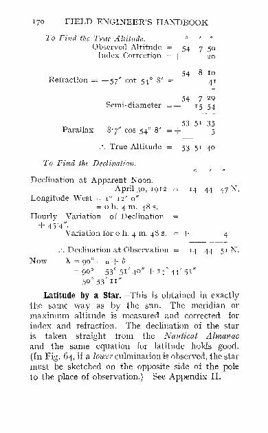
170 FIELD ENGINEER'S HANDBOOK
To Find tlw True Altitude. Observed Altitude
Index Correction
Refraction = -57" cot 54° 8'
Semi-diameter
Parallax = 8'7" cos 54° 8'
.'. True Altitude
To Find the Declination.
Declination at Apparent Noon, April 30, Ig12
Longitude West = 1° 12' 0"
= 0 h. 4 m. 48 s. Hourly Variation of Declination
+ 4)"4'" Variation for 0 h. 4 m. 48 s.
=+
=+
.'. Declination at Observation N ow A. = go 0 - a + (j
54 7 50 20
54 8 10 41
54 7 2g
15 54
53 51 35 5
53 51 40
o
14 44 47 N.
+ 4
L~ 44 SIN.
= goO - 53° 51' 40" + 140 44' .5 1 "
= .500 .53' II"
Latitude by a star.-This is obtained in exactly the same way as by the sun. The meridian or maximum altitude is measured and corrected for index and refraction. The declination of the star is taken straight from the Nautical Almanac and the same equation for latitude holds good. (In Fig. 64, if a lmc-er culmination is observed, the star must be sketched on the opposite side of the pole to the place of observation.) See Appendix II.

ASTRONOMY 171
EXAMPLE 12
At a place south of the equator the meridian altitude of a Coronae was 70° 5' 30"; the star being north of the observer. If the declination of a Coronae is S. 3So 2' 23", find the latitude of the place. Index correction = -I' 20".
To Find the True Altitude. Observed Altitude = 70 5 30
Index Correction = -' I 20
70 4 10 Refraction = -57" cot 70° 4' = - 21
.'. True altitude = 70 3 49
.', Latitude = goO - a + (j = S. 57° 5S' 34/1.
EXERCISES
1. An observation was made at the Cape of Good Hope (Longitude ISO 2S' 40" E.) at 10 A.M. April 15, 1912, Local Mean Time. Find (I) the Greenwich Mean Time; (2) the R.A. of the Mean Sun; (3) the R.A. of the observer's meridian, for the moment of the observation.
Answer.-(I) 20 h. 46 m. 5'3 s. April 14, (2) I h. 32 m. 34'0 s. (3) 23 h, 32 m. 34'0 s.
2. An observation of ~ Hydri (R.A.=o h. 21 m. 17'1 S,
on August 10, 1912) was made at 13 h. 12 m. 11'5 s., August 9, IgI2, at Brisbane (Longitude 153° I' 36" E.). Find: (I) the R.A. of the Meridian; (2) the Hom Angle of ~ Hydri.
Answer.-(I) 22 h. 23 m. 7'6 s. (2) 22 h. I m. 50'5 s.
3. At a place 3° 0' 0" East of New York (Longitude 73° 57' 30" W.) an altitude of Aldebaran (a Tami) was measured. The time on a New York chronometer was September 26, 1912, 14 h. 10 m. 5 s. From the altitude it was deduced that the westerly hour angle of Aldebaran was 22 h. 16 m. I'S s. What was (I) the true local mean time of the observation, (2) the error
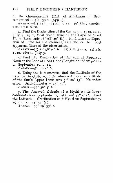
172 FIELD ENGINEER'S HANDBOOK
of the chronometer? (R.A. of Aldebaran on September 26 = 4 h. 30 m. 54'9 s.)
Answer.-(I) 14 h. 24 m. 7'3 s. (2) Chronometer 2 m. 2'3 s. slow.
4. Find the Declination of the Sun at 3 h. 15 m. 14 s., July 3, 1912, local mean time at the Cape of Good Hope (Longitude 18° 28' 40" E.). Find also the Equation of Time for the moment, and deduce the Local Apparent Time of the observation.
Answer.-(I) 22° 58' 40" N. (2) 3 m. 57'1 s. (3) 3 h. I I m. 16'9 s., July 3.
5. Find the Declination of the Sun at Apparent Noon at the Cape of Good Hope (Longitude 18°28' 40" E.) on September 10, 1912.
Answer.-5° 0' 25" N. 6. Using the last exercise, find the Latitude of the
Cape of Good Hope, if the observed meridian altitude of the Sun's Upper Limb was 51° 20' 13". No index error. Semi-diameter = 15' 55".
Answer·-33° 56' 4" S. 7. The observed altitude of {3 Hydri at its lower
culmination on September 7, 1912, was 47° 5' 4". Find the Latitude. (Declination of (3 Hydri on September 7, 1912 = 77° 44' 38" S.)
Answer.-59° 19' 33" S.

CHAPTER XII
DETERMINATION OF AZIMUTH AND TIME
AZIMUTH is another word for bearing. I t is the angle that a line makes with the true meridian or north-and-south line that passes through the place of observation.
, Consider Fig. 65. Suppose that a traverse is to be made for a railway
running approximately in an easterly direction from P to Q. (See Fig. 65.) Suppose, to fix our ideas, that the railway is approximately i.n latitude 50°, and that Q is a place on it, seven miles from P, and that PQ is straight. In order to obtain the bearing of the first course, the surveyor would determine the azimuth of the course astronomically. Let us suppose that the bearing of this first course is N. 86° 00' W. The surveyor would continue along the course until he reached Q. The bearing of the line PQ would still be N. 86° 00' W., but, if the azimuth of PQ were determined astronomically at Q, it would be found to be about N. 86° 07' W. This difference between the observed azimuth and calculated bearing (in most cases PQ would consist of a number of courses at various angles) is not an error, but is due to the , convergence of the meridians,' which in this particular latitude is about one minute per mile of departure.

174 FIELD ENGINEER'S HANDBOOK
The convergence of the meridians is due to the fact that no two adjacent north-and-south lines are parallel (except at the equator), since if continued along the sphere they meet at the pole.
For any other latitude the apparent error (it is not a real error) due to the convergence can be found from the following formula:
1
R
FIG. 65
log c = 4:2164 + log tan A, + log d
where c = the convergence in minutes, A, = the mean latitude in \'ihich PQ is situated,
and d = the departure of the line PQ in feet.
EXAMPLE 13
P is in latitude 53°, Q is in latitude 52° 36'. Departure of the line PQ = 50,000 feet. Find the convergence.
In this case A = 52° 4S', d = 50 ,000 .
. . log c = 4.2164 + 0·1197 + 4.6990 = 1"035 1
... c = 10·S minutes

DETERMINATION OF AZIMUTH AND TIME 175
Azimuth is better measured as a Nautical Bearing than as a whole circle bearing. It is allotted the symbol A.
The object of this chapter is to show how to find the azimuth or true bearing of a line EF. The method of procedure is shown in Fig. 66.
Fig. 66 represents a plan of the line EF. The theodolite is set up at P. The position of the meridian NS through P is to be found, and from it the azimuth
e:
Svn o .... 5t'a ...
FIG. 66
or bearing of the line EF. At a certain moment the altitude of the sun or of a star is measured, and at the same moment the angle 8 between the ' referring object' ¥ and the sun (or star) is measured. This concludes the field-work.
From the altitude of the su1t~or star the azimuth of the sun (or star) or the angle A is calculated: we can then find the azimuth of EF for it is South (8 - a) East. That is, in the figure, we measure 8 and find it to be 154°, we measure the altitude of the

176 FIELD ENGINEER'S HANDBOOK
sun and find it to be 38°. From this altitude we calculate that A = 76°. Therefore, the azimuth of EF = S. (I54° - 76°) E. = S. 78° E. Evidently the
\ ~
FIG. 67
only difficulty in the problem is the calculation of A, the azimuth of the sun (or star) at the moment of observation, the only data being its altitude, the approximate time, and the latitude. We will now discuss this problem.

DETERMINATION OF AZIMUTH AND TUITE In
Given the Altitude of the Sun, the Approximate Time, and the Latitude of the Observer, to Find the Azimuth of the Sun.-First correct the altitude of the sun as described on page r64. Secondly, find the declination of the sun at the moment of the observation, as described on page r62. Consider Fig. 67.
Fig. 67 represents the fixed celestial sphere, the north and south celestial poles being C and D. It is much the same as Fig. 60, but it is not drawn in perspective. In the middle of the sphere is the earth, which is rotating round CD. The figure represents
FIG. 68
the state of affairs just at the moment of the observation, and the sphere is, for convenience, being looked at from such a direction that the meridian of the observer is in the plane of the paper at the moment of the observation: that is, the circle is the meridian of P. The little tangent at P again represents the horizontal plate of theodolite, but XY is again virtually the plate.
The position of the sun at the instant of observation is S: it is on the surface of the sphere. . The latitude of P (A), the declination of S (0), and the altitude of S (a) are as marked in the figure. Since the required angle A, the azimuth of the sun, is the
N

178 FIELD ENGINEER'S HANDBOOK
horizontal angle between the meridian of P and the sun, it must be the angle marked A in the figure. .
Consider now the spherical triangle CZS: it has been transferred to Fig. 68 for clearness. It is a triangle whose sides are goO - '" goO - 0, and goO - a. ", 0, and a are aU known, so that we can find the angles of the triangle. From equation 3, Appendix HI-. A
SIn - = 2 /----------a-+~"~+-g~oO~o~--a-+-"~---go~o~+~S
V sec a sec" cos 2 cos 2
This determines A, from which the azimuth of EF is easily found as described at the beginning of the chapter.
NOTE.-In the above formula A is the azimuth of the sun or star measured from the south; a is the altitude of the sun or star; 0 is the north declination of the sun .or star; "is the north latitude of the observer. Suppose in an actual observation the declination is 30° South, and the latitude 50° South, we simply substitute 0 = - 30°, " = - 50° in the formula, which still gives us the azimuth from the south. Whether the azimuth so found is west or east from the south, merely depends upon whether the star is setting or rising. Remember that-
sec (- x) = sec x and cos (- x) = cos x.
Practical Rules for making the Observation.Evidently an observation made to find the azimuth of the sun or of a star should be made when the azimuth is changing very slowly. Hence this observation should be made when the sun or star is far from the meridian (for the sun, this occurs in the early morning or late afternoon). This is very
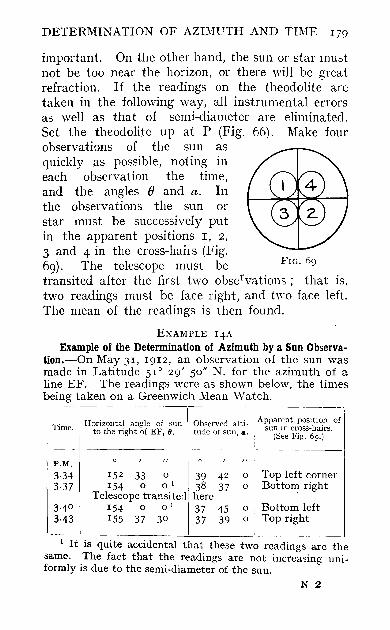
DETERMINATION OF AZIMUTH AND TIME 179
important. On the other hand, the sun or star must not be too near the horizon, or there will be great refraction. If the readings on the theodolite are taken in the following way, all instrumental errors as well as that of semi-diameter are eliminated. Set the theodolite up at P (Fig. 66). Make four observations of the sun as quickly as possible, noting in each observation the time, and the angles e and a. In the observations the sun or star must be successively put in the apparent positions I, 2,
3 and 4 in the cross-hairs (Fig. 69). The telescope must be transited after the first two observations; that is, two readings must be face right, and two face left. The mean of the readings is then found.
EXAMPLE 14A
Example of the Determination of Azimuth by a Sun Observation.-On May 31, 1912, an observation of the sun was made in Latitude 51° 29' 50" N. for the azimuth of a line EF. The readings were as shown below, the times being taken on a Greenwich Mean \Vatch.
I
Time.
P.M.
3·34 3·37
3.40
3-43
Horizontal angle of SUll
to the righ t of EF, e.
152 33 0
154 0 0'
Telescope transited 154 0 0'
155 37 30
--~~-----
Observed alti- I A~~~rf:~r~~~~~~~~. of tude of sun, ". (See Fig. 69.)
39 42 0 Top left corner 38 37 0 Botto~ right here 37 45 0 Bottom left 37 39 0 Top right
1 It is quite accidental that these two readings are the same. The fact that the readings are not increasing uniformly is due to the semi-diameter of the sun.
N 2

180 FIELD ENGINEER'S HANDBOOK
By finding the mean of these readings, we see that; At 3 h. 38 m. 30 s., lvlay 31,1912, Greenwich 1vIean Time, the altitude of the sun was ' observed' to be 38° 26',' the horizontal angle of the sun to the right of EF was' observed' to be 154° 2' 37". To Find A, the Azimuth of the Sun,
Observed altitude Sun's Parallax = +8'7 cos 38° 26' = +
Refraction = - 57" cot 38° 26' I 13
.', True altitude a
N.A., Sun's apparent declination at G.M.N., May 31, 1912
Greenwich M~an Time of Observation = 3 h. 38 m. 30 s., May 3I.
21 54 30N.
N.A. Variation in declination = + 21 '4" per hour. For 3 h. 38 m. 30 s. = + I 17
.'. Declination at observation = 21 55 47 N.
Latitude of Observer = 51° 29' 50". ,'. a = 38° 25' 45", A = + 51° 29' 50", (j = + 21° 55' 47"
whence
and 2
Applying the formula of page 178 ; log sec a log sec A
a + A + 90°- (j log cos = 2
log cos a + A-90° + (j 2
I . A , , 2 og sm ~2
I . A ,', og sm - = 2
'1060391 '2058239
1'2806635
1'992053 1

DETERMINATION OF AZ1MUTH AND TIME lSI
Since the sun was setting, this azimuth is west; therefore sun's azimuth at observation = S. 76° 36' 40" w.
To Find the Azimuth of EF.-Evidently from Fig. 66 the azimuth of EF is the same as the azimuth of the sun (S. 760 36' 40" W.), but deflected 15402' 5i' to the left.
Therefore the azimuth of EF is S. 77° 26' Ii' E.
If a star had been used instead of the sun, the work would have been even simpler, since the time need not be known, as the declination of a star is constant. Two observations only, one face right and the other face left, need be made, as a star has no semi-diameter. The calculations are precisely the same. Example 14B \vill make this clear.
EXAMPLE I4B
Example of the Determination of Azimuth by a Star Observation.-At a place in latitude 1° 32' North, on l\Iarch II, 1913, Sirius (a Canis Majcris, declination can be found on page 198) was observed while rising for the azimuth of a line EF. The theodolite was set up at E, and two observations (one face right and the other face left) were made. The mean altitude of Sirius was 45° 05', and the mean angle of Sirius to the right of F was la° 17'. Find the azimuth of EF (without using the almanac).
and
Observed Altitude Refraction = -57" cot 45° 05'
... True A ltitude a
45 05 I
45 04
Latitude A = + 1° 32'. Declination (j = - 16° 36 '
a + A + 90° - (j . 2 = - 76° 36'

182 FIELD ENGINEER'S HANDBOOK
To Find A, the Azimuth of Sirius, apply the formula of page 178.
log sec 45° 04' = '1510209 log sec 1° 32' = '0001555
log cos 76° 36' = 1'3650158 log cos (- 30° 00') = 1'9375306
and
. A -.'. 2 log sm - = 1'4537228
2
A -.. log sin = 1'7268614
2
A .'. "2 = 32° 13'
A = 64° 26' = S. 64° 26' East (for a rising
star). Now Sirius was 10° Ii to right of F,
.. Azimuth of EF = S. 74° 43' E.
THE DETERl\IINATION OF TIME
Local time may easily be found from the same observation that has found azimuth. An approximation to the time has to be known; the latter could be found by applying the equation of time to the time of the sun crossing the meridian.
Consider Fig. 67. From the definition of hour angle (page 158), it. is
evident that SCZ is the hour angle of the sun or star. Hence (see Appendix III) the hour angle h is given by-
h SIll

DETERMINATION OF AZIMUTH AND TIME 183
The same note applies to this formula as to that of page 178.
The hour angle is easterly if the sun or star is east of the meridian, and, if so, it must be turned into a westerly hour angle by subtracting it from 360°. In any case it must be turned from degrees into hours.
For a Sun Observation. - Evidently, from page 158, the vVesterly Hour Angle of the Apparent Sun = the Apparent Time at the Place. Hence the apparent time can he found, and can be turned into mean time by means of the equation of time (see Example 9).
For a Star Observation.-The local mean time is got from the fundamental equation of page 158, namely- .
Mean Time at Place = W. Hour Angle of Star + R.A. of Star - R.A. of Mean Sun.
In finding the Right Ascension of the Mean Sun, the approximate time must be used.
THE DETERMINATION OF LONGITUDE
If local mean time is known, and if the observer can find the mean time at some standard place whose longitude is known accurately (such as Greenwich, Paris, or New York), he can find his longitude, since for each hour that local time is behind, say, New York time, the observer is IS° \V. of New York. He can find the mean time at the standard meridian either by transporting chronometers from that meridian, or by receiving a telegraphic signal from that meridian. The latter is the better way, but is very difficult to arrange.

184 FIELD ENGINEER'S HANDBOOK
EXERCISES
1. At Brisbane (Latitude 27° 28' 00" S.), Sirius (a Canis Majoris, declination = 16° 35' 26" S.) was observed for the azimuth of a line EF on August 10,1912. The star was rising. The theodolite was set up at E. Two observations were made as quickly as possible, the mean corrected altitude of Sirius being 35° II' 10",
and the mean horizontal angle of Sirius to the right I
of F being 320° 5' ro". Find (1) the azimuth of Sirius, (2) the azimuth of EF. Answer.-(r) S. 88° 26' 20" E. (2) S. 48° 31' 30" E.
2. In the last exercise find the hour angle of Sirius. If the RA. of Sirius is 6 h. 40 m. 22 s., find the true local mean time of the observation, if it was known that the local time was roughly 5.30 A.M. Longitude of Brisbane ro h. 12 m. 6"4 s. E.
Answer.-(I) 20 h. 6 m.32 s. W. (2) 17 h.34 m. 57"2 s., i.e. 5 h. 34 m. 57"2 s. A.M.
I A transit plate is graduated clock',\"ise. If, therefore, the plate was clamped at zero when F was sighted, the rcading on Sirius would have been 320° 5' 10 , even though the telescope might have been turned to the left.

CHAPTER XIII
THE POLE STAR
THE Pole Star (also known as Polaris, the North Star, a Ursae Minoris, La Polaire, and a Petite Ours e) is a star situated very near the North Celesti2.l Pole, and in the Northern Hemisphere can usually be seen very clearly. An observer on the earth sees this star describe 8 very small circle round the Pole during a day. The Pole Star gives us a convenient means of finding latitude and azimuth.
Latitude from the Pole Star (at any Momentl.From Fig. 64 it is evident that the altitude of the celestial pole is equal to the latitude of the observer. Hence the altitude of the Pole Star at any moment is an approximation to the latitude of the observer. If the local time of the observation is known fairly accurately, the altitude of the Pole Star can be adjusted so as to give us the altitude of the Pole, which is the latitude of the observer. The requisite adjustment consists of three corrections, each of which is taken from a table in the Nautical Almanac.
Description of the Work.-At any moment observe a single altitude of the Pule Star, and note the local time. Correct the altitude for Index Error and Refraction, and subtract from it r'. Find the Right Ascension of the Meridian of the place of observation

186 FIELD ENGINEER'S HANDBOOK
at the moment of the observation (see Example 4) : this will now be given the name Local Sidereal Time (L.S.T.). With the Local Sidereal Time (or R.A.M.) just found, take the first correction from Table r, and apply it (with its proper sign) to the reduced altitude.
With the latest altitude and local sidereal time, take the second correction to the altitude from Table II; and with the day of the month and the local sidereal time, take the third correction from Table III. These last two corrections are to be added. The final altitude is the required latitude.
EXAMPLE 15
On March 6, 1912, in Longitude 37° W., at 7 h. 43 m. 0 s. P.M. (local time), the altitude of the Pole Star, when corrected for Index Error and Refraction, was 46° 17' 28". Find the Latitude.
Find the R.AJ'd. or L.5.I. h. m. s,
Mean time at place = 7 43 0, March 6 Longitude = 37° W. = 2 28 0
.'. G.lVLT. of Observation = 10 II 0, March 6
h. m. s. N.A., H .. A. of Mean Sun at G.M.N. = 22 55 24
(in the N.A. called Sidereal Time at G.M.N.) Ill. s. Acceleration for 10 h. = I 39
Acceleration for II m. = 2
.'. Acceleration for 10 h. II m. 0 s. = I 41 I 41
.. H..A. of Mean Sun at Observation Mean time at place
.'. R.A. JI. or L.5. I. of Observation
22 57 5 7 43 0
30 40 5 6 40 5
THE POLE STAR
Corrected altitude Subtract I'
. '. Reduced Altitude
46 17 28 I 0
From Table I, if L.S.T. = 6 h. 40 m. 5 s., Filst Correction = - 0° 14' 14" .
. '. Altitude becomes 46° 2' 1{"
From Table II, if L.S.T. = 6 h. 40 m. 5 s., and Altitude = 46° 2' 14", Second Correction = + 0' 40"
.'. Altitude becomes 46° 2' 54"
From Table III, if L.S.T. = 6 h. 40 m. 5 S., and date = March 6, Third Correction = + 0° I' II"
. '. Altitude becomes 46° 4' 5"
.'. Required Latitude = 46° 4' 5"
Azimuth from the Pole Star (at its Culmination).-This is a very simple method of obtaining azimuth; it does not involve the use of any calculations at all.
When the star Zeta Ursae Majoris is vertically above or below the Pole Star (as found by a plumbline), the Pole Star is at its lower or upper culmination and is due north of the observer.
Zeta Ursae Majoris is a star in the constellation Great Bear or Plough. This constellation is shaped like a saucepan: Zeta is the middle of the three stars which form the handle of the saucepan.
Field-work.~When Zeta Ursae Majoris is vertically above or below the Pole Star, sight on the Pole Star with the telescope face right, and the plates clamped. Depress the telescope and (with the help
188 FIELD ENGINEER'S HANDBOOK
of a light) set a hub on the ground so that it is bisected by the cross-hairs. Repeat the operation with the telescope face left, setting another hub. Bisect the distance between these two hubs with a third hub. The latter hub is now due north of the instrument. (The star 0 Cassiopeiae can also be used, but the Pole Star is at its lower culmination when 0 Cassiopeiae is below it.)
The disadvantages of this method are: (r) That it is not the most accurate method; (z) That it can only be used in the N OJ them Hemisphere; (3) That the culmination may occur at an inconvenient time such as 3 A.M.; (4) That at certain times of the year and in certain latitudes the culminations may occur during daylight.
Other methods C£ using the Pole Star for observation occur in the next chapter, as the Pole Star is a circum-polar star.
Azimuth from the Pole Star (at any Moment).The Azimuth of a line EF is found at any moment from the Pole Star in the following way: The theodolite is set up at E, and at a certain moment the horizontal angle between F and the Pole Star is observed. (N OTE.-It is necessary to observe the horizontal angle face right and face left as quickly as possible and take the mean.) This concludes the field-work.
From the time, the hour angle of the Pole Star is calculated as described in Example 5. It is assumed that the observer's latitude has already been found. With the hour angle just found and the known latitude, the azimuth of the Pole Star is taken from a table. The requisite table is called 'Table des Azimuts de la Polaire,' and is in the Connaissance

THE POLE STAR. 189
des Temps, published by the Bureau des Longitudes, Paris: it is the French Nautical Almanac.
The azimuth of the Pole Star at a given moment being known, and the angle between F and the Pole Star at the same moment being known, the azimuth of EF can be found.
If the hour angle of the star is between 0 h. and I2 h., the azimuth is West of North; if between I2 h. and 24 h., it is East of North. In the tables a comma signifies a decimal point.
EXAMPLE r6
In Example IS, the theodolite was at E, and the Pole Star was 293 0 S' to the right of EF. Find the azimuth of EF.
From Example IS- h. In. s. R.A.M. or L.S.T. at Observation = 6 40 S
N.A., R.A. of the Pole Star, March 6, 1912 = I 27 34
... Hour angle of the Pole Sta·r = S 12 31
From Example IS-
Latitude of Observer = 46° 4' S"
From' Table des Azimuts '-If Hour Angle = S h. 12 m. 31 S., and Latitude = 460 4' S"
Azimuth of Pole Star = 1° 38·r' = N. 1 0 38' W. (in this case) .
... Azimuth of EF = N. 294 0 43' W. = N. 6So 17' E.

CHAPTER XIV
OTHER METHODS OF FINDING AZIMUTH AND LATITUDE, AND GENERAL NOTES ON ASTRONOMICAL OBSERVATIONS
IN this chapter are given methods of finding azimuth and latitude by observations of circum-polar stars. In each method it is necessary to know the local mean time roughly. In each method it is desirable to observe a star as near as possible to the Pole.
The Determination of Azimuth from a Circumpolar Star at Elongation.-This is a popular method of determining azimuth.
A circum-polar is a star that never goes below the horizon, and hence must have a declination greater than 90° minus the latitude of the place.
A circum-polar star is said to be at elongation when it attains its greatest distance east or west of the meridian.
A circum-polar star can only elongate if its declination is greater than the latitude of the place.
Evidently, in Fig. 67 or Fig. 68, the star S is at elongation if the angle CZS = 900.
Since at elongation the angle CZS = goO, we have from spherical trigonometry-

OTHER METHODS OF FINDING AZIMUTH 191
tan A(I) COS h =--"
tan v () . A cos 6 2 SIn =-
cos A-. sin A-
(3) sm a = -.-~ SIn 0
From (I) the hour angle of the star can be found for the moment of its elongation. It will be an easterly or westerly hour angle according as the elongation is easterly or westerly. Always turn an easterly hour angle into a westerly one by subtracting it from 360°.
From the fundamental equation on page 158, or from Example 6 (part I), we can find the local mean time at which the star attains this hour angle. (This time may be found either by the accurate or by the approximate way. A star moves so slowly in azimuth at elongation that a small error in time is of little consequence.) Hence we can find the local mean time at which elongation occurs, and we therefore know when to observe the star.
Field-work.-Set up the theodolite about a quarter of an hour before the calculated time of elongation. As nearly as possible to the moment of elongation, measure the horizontal angle between the star and the line whose azimuth is to be found. This angle must be measured both face right and face left.
This concludes the field-work. From equation (2) we can calculate the azimuth
of the star at the moment of its elongation, and from it calculate the azimuth of the line or referring object. An example will make this clear.
EXAMPLE 17
On October 24, I9I2, on Barnes Common (Latitude 51° 28' N.), (j Ursae Minoris is to be observed at westerly
192 FIELD ENGINEER'S HANDBOOK
elongation for the azimuth of a line EF. (.3 Ursae Minoris, RA. = 18 h. 0 m. 38 s., .3 = 86° 36' 51" N.)
(a) Find the hour angle of the star.
cos h = tan A tan .3
log tan 51° 28' = '0988763 log tan 86° 36' 51" = 1'2282726
log cos h = 2'8706037 .'. h = 85° 15'
= 5 h. 41 m. 0 s. (b) Find the approximate watch time at which the
observation is to be made.
R.A. of Mean sun at G.M.N., October 24 + Approximate Mean Time at Barnes = R.A. of Star + Hour Angle of Star.
.'. Approximate Local Time = 18 h. 0 m. 38 s. + 5 h. 41 m. 0 s.~ 14 h. 10 m. 5 s. = 9 h. 31 m. (c) Find the azimuth of the star at this time.
. eos .3 sm A = cos A
log cos 86° 36' 51" = 2 '7709697 log cos 51° 28' = 1'7944670
log sin A = 2'9765027 .'. A = 5° 26'
This will be N. 5° 26' W., since the elongation was westerly.
(d) If by the observation it was found that the star was 200° 51' to the right of F, what is the azimuth of EF?
Azimuth = N. 206°17' \V. = S. 26° 17' E.
N oTE.-In the example it might have been difficult to find the star. If the approximate north was known before the observation, the star could have been found

OTHER METHODS OF FINDING AZIMUTH 193
by its computed azimuth (N. 5° 26' W.) and by its
l 'd I . l'h" b' sin "A, a btu eat e ongatlOn, w lIC IS gIven y SIll a =-.-,,' SIn 0
In this case the altitude would have worked out to be SIo 36' from this formula.
The Determination of Azimuth from a Circumpolar Star at Culmination.- This is a quick and simple way of determining azimuth, though it is not so accurate as the observation when the star is at elongation, because in this case the star is moving comparatively quickly in azimuth.
Compute the local mean time of transit or culmination accurately. This can be done by Example 6, remembering that at transit or culmination the star's hour angle is either zero or I2 hours, according as the transit is an upper or a lower one. At the computed moment bisect the star and find the horizontal angle (first face right and then face left, taking the mean reading) between it and the line whose azimuth is to be determined. This reading is the required azimuth.
The Determination of Latitude from a Circumpolar Star at Culmination.-This method is exactly the same as that of finding latitude by a meridian altitude of the sun or of a star, with the exception that the meridian altitude is not found by plotting a curve (see page I68), but is found by actually measuring the altitude at the moment of culmination, the moment of culmination being calculated as for the last article.
There are many circum-polar stars that could be used for these observations, but the Pole Star and o Ursae Minoris are most suitable in the Northern
o

194 FIELD ENGINEER'S HANDBOOK
Hemisphere, and fJ Hydri and fJ Chamaeleontis are most suitable in the Southern Hemisphere. Other stars, however, can be used if these stars culminate or elongate at inconvenient times.
GENERAL NOTES ON ASTRONOMICAL OBSERVATIONS
Several methods have been given of observing the sun and stars. It is impossible to lay down rules as to which should be observed. For instance, it would not be advisable to observe the sun during winter in very high latitudes, or a star near the Pole in very low latitudes, because in both cases they would be too near the horizon to make refraction a certain quantity. The advantage of observing the sun is that the observation is made in daylight. The disadvantage is that the sun's semi-diameter has to be accounted for or eliminated, and that (for finding azimuth) approximate Greenwich time must be known or computed, as the sun's declination changes. The first method of finding azimuth by the stars does not involve any knowledge of time. It is useful to realise that a fixed star is to be found in the same place (azimuth and altitude) every day, though the time at which .it is in this place is about four minutes earlier each day.
Sun GIass.-Whenever the sun is being observed, a dark glass must be fitted on to the eye-piece. This is supplied with the instrument.
Diagonal Eye-piece.-For observing high altitudes, a diagonal or prismatic eye-piece should be used.
Night Lights.-A suitable reference mark for azimuth observations is obtained by putting a piece
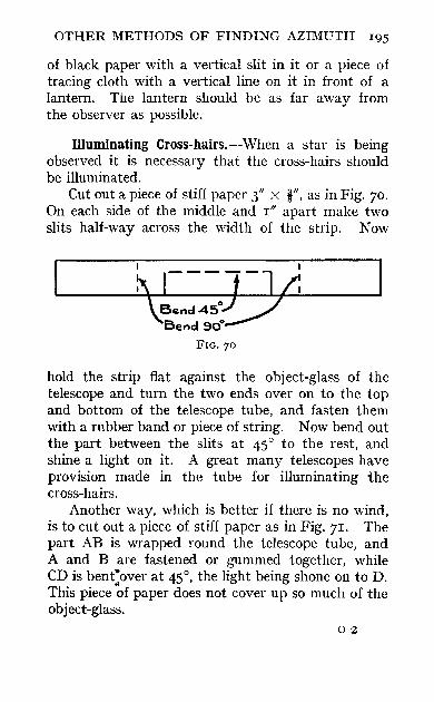
OTHER METHODS OF FINDING AZIMUTH 195
of black paper with a vertical slit in it or a piece of tracing cloth with a vertical line on it in front of a lantern. The lantern should be as far away from the observer as possible.
llluminating Cross-hairs.--When a star is being observed it is necessary that the cross-hairs should be illuminated.
Cut out a piece of stiff paper 3" X i", as in Fig. 70. On each side of the middle and I" apart make two slits half-way across the width of the strip. Now
hold the strip flat against the object-glass of the telescope and turn the two ends over on to the top and bottom of the telescope tube, and fasten them with a rubber band or piece of string. Now bend out the part between the slits at 45° to the rest, and shine a light on it. A great many telescopes have provision made in the tube for illuminating the cross-hairs.
Another way, which is better if there is no wind, is to cut out a piece of stiff paper as in Fig. 71. The part AB is wrapped round the telescope tube, and A and B are fastened or gummed together, while CD is bent:over at 45°, the light being shone on to D. This piece of paper does not cover up so much of the object-glass.
02

196 FIELD ENGINEER'S HANDBOOK
Identification of Stars.--Before the reader observes stars, he should be able to identify them. This may be done with the help of star charts, of which there are many in existence. It is not proposed to give any here, but the following short description
A c B
FIG. 71
of the principal stars may be of use. The description is taken from 'Kempe's Engineer's Year Book,' 1912 edition. One or two slight alterations have been made to it:
The angular distance between two stars can be closely estimated by comparison with half the distance between the point overhead and the horizon, i.e. 45°, or by the distance between the Pointers in Ursa Major (the Great Bear), i.e. 5°.
(a) In the constellation Ursa Major the two wellknown stars a and {3 (The Pointers) point directly to Polaris, the Pole Star. The latter also forms the end or tail of Ursa Minor.
(b) If the curve of the tail of Ursa Major be continued, about 30° along will be found Arcturus (a Bootes).
(c) A line from Polaris at right angles to the line from the Pointers gives, 50° from the former, Capella (a Aurigae).
(d) A line from Polaris through the last star but one of the tail of Ursa Major passes through Spica (a Virginis) , 30° beyond Arcturus.

OTHER METHODS OF FINDING AZIMUTH 197
(e) The Pointers' line continued, through Polaris for 60° indicates the Great Square of Pegasus. The star in the corner opposite to the Pole is Markab (a Pegasi).
(1) Midway between the Square and Polaris is the constellation Cassiopeia (five stars grouped like Wi.
(g) A diagonal through the square S.E. to N.W. produced 40° gives Deneb (a Cygni).
(h) 25° farther and 10° to the right, the same line gives Vega (a Lyrae), a large white star.
(j) 35° south of Deneb and Vega is Altair (a Aquilae). This star is between companions, and forms the apex of an isosceles triangle with Deneb and Vega.
(k) A line from Polaris through Capella will touch Rigel, 65° from Capella. This line passes between ruddy Aldebaran (a Tauri) , 10° west and 30° from Capella, and ruddy Betelgeuse, 10° east and 40° from Capella. Rigel (f3) and Betelgeuse (a) are diagonal stars in Orion.
(t) A line from Aldebaran through Orion's Belt passes near Sirius (a Canis Majoris) at an equal distance from Aldebaran. Sirius is the brightest star in the heavens.
(m) 50° east of Betelgeuse, forming nearly an equilateral triangle with Betelgeuse and Sirius, is Procyon (a Canis Minoris).
(n) 30° north of Procyon is Castor (a Geminorum), and 5° S.E. of Castor is Pollux ([3 Geminorum).
(0) The apex of an isosceles triangle with Castor and Procyon, 45° east, is Regulus (a Leonis).
(P) Eastward from Procyon to Regulus, 30°, is Denebola ([3 Leonis). Denebola forms an equilateral triangle with Arcturus and Spica.
Planets.--Besides the fixed stars, the planets Venus, Mars, Jupiter, and Saturn are often conspicuous objects in the heavens. Care must be taken that these are not mistaken for stars. Their positions (RA. and 0) can be found for any date in the Nautical
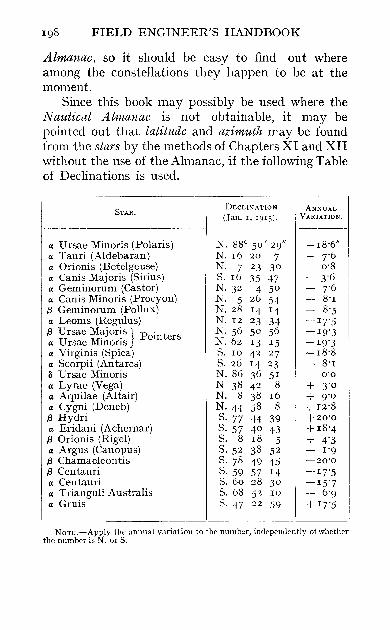
198 FIELD ENGINEER'S HANDBOOK
Almanac, so it should be easy to find out where among the constellations they happen to be at the moment,
Since this book may possibly be used where the Nautical Almanac is not obtainable, it may be pointed out that latitude and azimuth may be found from the stars by the methods of Chapters XI and XII without the use of the Almanac, if the following Table of Declinations is used,
STAR. DECLINATION I ANNUAL
(jan. 1,1913). VARIATION. _________________________ ------------ i-------
a Ursae Minoris (Polaris) a Tauri (Aldebaran) a Orionis (Betelgeuse) a Canis Majoris (Sirius) a Geminorum (Castor) a Canis Minoris (Procyon)
{3 Geminorum (Pollux) a Leoms (Regulus)
{3 Ursae M~jor~s I Pointers a U rsae Mmons j' a Virginis (Spica) a Scorpii (Antares) /j U rsae Minoris a Lyrae (Vega) a Aquilae (Altair) a Cygni (Deneb)
{3 Hydri a Eridani (Achemar)
{3 Orionis (Rigel) a Argus (Canopus)
{3 Chamaeleontis {3 Cen1.auri a Centauri a Trianguli Australis a Gruis
I
N, 88° 50' 29" N,I6 20 7 N, 7 23 30 S, 10 35 47 N,32 4 50 N, 5 26 54 N,28 14 14 N,I2 23 34 N,56 50 56 N,62 13 15 S, 10 42 27 S, 26 14 23 N.86 36 51 N 38 42 8 N, 8 38 16 N'H 58 8 S, 77 H 39 S. 57 40 43 S, 8 18 5 S,52 38 52 S, 78 49 45 S, 59 57 14 S, 60 28 30 S,08 52 10 S. 47 22 59
+ 18'6" + ]'6 + 0'8 - 3'6 I
- ]'6 i - S'I - 8" .~ -17'5 -19'3 -19'3 -18'8 - S'I
0'0 + 3'0 + 9'0 +I2'8 +20'0 +18'4 + 4'3 - 1'9 -20'0
-11'5 -15'7 - 6'9 + 17'5
NOTE.-Apply the annual variation to the number, inc1ppemkntly of whether the numbpr is N. or S.

LIST OF ABBREVIATIONS USED IN THIS BOOK
L.M.T. G.M.T. L.A.T. G.A.T. RA. R.A.M.5. L.S.T.
or R.A.M. (j
a h A A y
}
Local Mean Time. Greenwich Mean Time. Local Apparent Time. Greenwich Apparent Time. Right Ascension. Right Ascension of the Mean Sun. Local Sidereal Time
or Right Ascension of the (local) Meridian. Declination. Altitude. Hour Angie. Latitude. Azimuth. The First Point of Aries.


APPENDICES
APPENDIX I
THE GENERAL SYSTEM OF LAND SURVEY IN CANADA
THE Dominion lands are divided by means of longitudinal and latitudinal lines into quadrilateral figures called Townships.
Each township contains thirty-six sections, each of one square mile in area; each section being subdivided into quarter sections, each containing one hundred and sixty acres. Fig. 72 represents a township divided into thirty-six sections numbered and bounded as shown.
The east and west boundaries of the township are true meridians, hence the northern sections will not be so wide as the southern sections owing to the convergence of the meridians.
The townships lie in columns or ' Ranges' which are numbered east and west from the meridians.
The principal or first meridian passes about twelve miles west of Winnipeg, longitude 97° 27' 9" west of Greenwich. The second meridian is placed about longitude 102°, and the third at 106°; each meridian after the second being four degrees east or west of the preceding one.
In subdividing the townships into sections, three main systems have been adopted; the main differences between the systems being chiefly in the methods of

202 FIELD ENGINEER'S HANDBOOK
separating the sections by means of road allowances, and in the methods adopted in allowing for the convergence of the meridians.
Fig. 73 shows a township subdivided according to the first and second systems.
I I I I 1 I I 1 I I I I
--31-- --32.-- --33-- --34-- --35-- --36--I I I 1 I I I I I I 1 I 1 1 I I 1 I I I I I I ,
--30-- --2.9-- --28-- --27-- -- 26-- --25--I I 1 I I I I I 1 I I I I I I I I I I I 1 I I 1
--19-- --20-- --2.1-- --22:-- --23-- -- 24---I I I I I I
<It" 1 1 I I 1 1 VW I I I I 1 1
I I I I I I --16-- --17-- --16-- --I!:'-- --14-- --10--
I 1 I I 1 I 1 1 I I 1 I
1 1 I I I I 1 I I 1 1 I
--7-- --8-- --9-- --10-- --11-- --12:--I 1 1 I I 1 I I I I I I I 1 I 1 1 I I I I I i I
--6-- --5-- ---.4--- --3-- --2.-- --1--I I I 1 I I 1 1 I 1 1 I
S FIG. 72
It will be noticed that each section is bounded on all sides by a road allowance of 99 feet in width.
The deficiency or surplus, resulting from the' want of parallelism of the meridians, is set out and allowed for in the column of sections adjoining the western boundary of the township.
The east and west boundaries of the township are true meridians, but the intermediate section lines are

APPENDICES
parallel to the eastern boundary. The only difference in system two from system one is in regard to the deficiency or surplus resulting from the convergence or divergence of the meridian.
This is distributed equally among all the sections,
FIG. 73
instead of being concentrated in the western columns of sections.
Fig. 74 shows a township subdivided according to the third system. In this system there is a road allowance of 66 feet running north and south between every section.
With regard to the road allowances running east and west, these only occur between every two sections
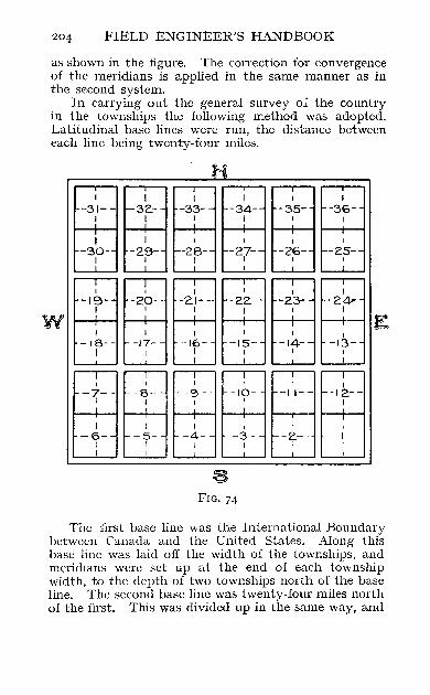
204 FJELD ENGINEER'S HANDBOOK
as shown in the figure. The correction for convergence of the meridians is applied in the same manner as in the second system.
In carrying out the general survey of the country in the townships the following method was adopted. Latitudinal base lines were run, the distance between each line being twenty-four miles.
H
~~~ I
~~ -34-
I
I
-30- -29- -28- -27- -26- -25-I I I I I I
I
Bj§[tjBj~ I
-19- -20- -2.1- -22.- -23- -2.4--
-,~-- "~- -,~- -,~- -,~-I
W E I
-13-I
I
ffirnrnm~8j -6- -5- -4- -3- -2.- -I-I ! I I I I
I I
FIG. 74
The first base line was the International Boundary between Canada and the United States. Along this base line was laid off the width of the townships, and meridians were set up at the end of each township width, to the depth of two townships north of the base line. The second base line was twenty-four miles north of the first. This was divided up in the same way, and
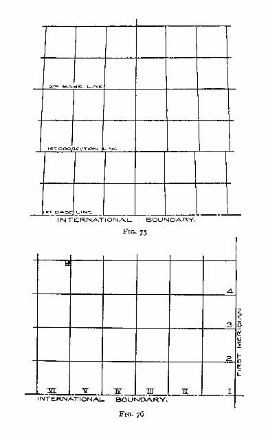
2 ... ., BASE. L-INE
1ST. C0'R..RE:CT10N 1...1 NE.
~T_~ _~_L...--__ I.....- .. _ ....... ______ -'--
INTE;R.NATIONAL BOUNDAR.Y.
FIG. 75
I:f
4
Z « 3 i5
(( w ~
2.~ It: iL
)IT V 1'l lIT -'iNTERNATiONA~-OU~AR.Y.
-1L_ '---~ I-

206 FIELD ENGINEER'S HANDBOOK
meridians were drawn twelve miles north and twelve south.
It will be seen therefore that the ends of the meridians midway between the two base lines did not meet, thus giving rise to what is called a Correction Line. Reference to Fig. 75 will make this clearer.
00 -=S~U::::.T..!.!.H~B~O~U~N""D,:..:A=R.~Y~O~F'"-R~O~A,,,O=::.. ___ -. I~O'" 1'05"1:
0 10
FIG. 77
a: II. o
~ ~ z :> o III
Iii ~
It will be seen that only those townships on a base line are the correct width, those south of a correction line being too narrow, owing to the convergence of the meridians, while those north of the correction line are too broad, owing to the divergence of the meridians.
The result of such a system of survey is that it is possible to determine the position of any place in Canada, when given the number of the section, the township, and the range in which that place is. For instance, in Fig. 76.
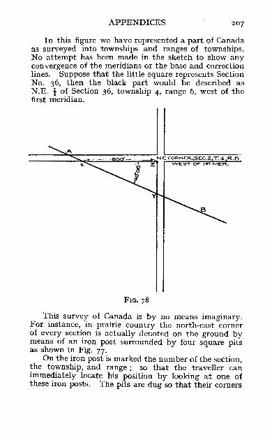
APPENDICES
In this figure we have represented a part of Canada as surveyed into townships and ranges of townships. No attempt has been made in the sketch to show any convergence of the meridians or the base and correction lines. Suppose that the little square represents Section No. 36, then the black part would be described as N.E. -! of Section 36, township 4, range 6, west of the first meridian.
-====:::S;~~~~QQ:~;;;;;;;;;~N'E: CORNE:R..,SEC.2. 1.4 R.B - x Z VVE:.8T OF" 1ST MeR.
FIG. 78
This survey of Canada is by no means imaginary. For instance, in prairie country the north-east corner of every section is actually denoted on the ground by means of an iron post surrounded by four square pits as shown in Fig. 77.
On the iron post is marked the number of the section, the township, and range; so that the traveller can immediately locate his position by looking at one of these iron posts. The pits are dug so that their corners

208 FIELD ENGINEER'S HANDBOOK
denote the cardinal points of the compass. When a railway is being surveyed, the centre line must be connected with all township or subdivision lines of land surveys in the vicinity by means of chainage and angle ties.
That is to say, the angle made by the railway line with each township, section, or other land line is observed by means of the theodolite. The chainage of the actual intersection of the railway with the land line is carefully determined, also the distance from the intersection along the land line to the nearest section corner. For instance, let Fig. 78 represent a part of a survey of a railway line.
The railway line is represented by AB. The chainage at which it cuts the land line at X and Y is noted, and the angle ZXY is read; also the distance of X from the iron post Z. The draughtsman would then have all the information necessary for locating the line on his map.
For further details regarding the system of survey in Canada the reader is referred to the 'Manual of Instructions to Dominion Land Surveyors,' issued by the Minister of the Interior for Canada.
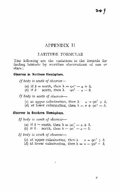
APPENDIX II
LATITUDE FORMULAE
THE following are the variations in the formula for finding latitude by meridian observations of sun or stars:
Observer in Northern Hemisphere.
If body is south of observer-
(a) if a = north, then A = goa - a + a. (b) if a = south, then A = goO - a - a.
If body is north of observer-
(c) at upper culmination, then A = a - goO + a. (d) at lower culmination, then A = a + goO - a.
Observer in Southern Hemisphere.
If body is north of observer-
(a) if a = south, then A = goO - a + a. (b) if a = north, then A = goO - a - a.
If body is south of observer-
(c) at upper culmination, then A = (1 - goO .+. 1\. (d) at lower culmination, then A = " + goO - a.
l'

APPENDIX III
SPHERICAL TRIGONOMETRY
A SPHERICAL triangle (such as we need to consider) is a triangle on a sphere, the sides of which are parts of ' great circles' of the sphere. A great circle is a circle on the sphere whose centre is the centre of the sphere.
In plane trigonometry we say that a side of a triangle is so many miles long, but in spherical trigonometry we say that it is so many degrees long, meaning that the side in question subtends so many degrees at the centre of the sphere.
Consider Fig. 79.
A
p
FIG. 79
ABC is a' spherical triangle. 0 is the centre of the sphere. Join OA, OB, OC. a, b, and c are the sides of the triangle, so that L AOB = c, L BOC = a, L AOC = b.
Suppose that we know the values of a, b, and c; it is required to find the value of A.
Draw the tangent at A to the circle AB; let it meet OB in P,
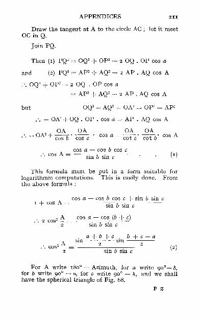
APPENDICES 2II
Draw the tangent at A to the circle AC; let it meet OC in Q.
Join PQ.
Then (I) PQ" = OQ2 + Op2 - 2 OQ . OP cos a
and (2) PQ2 = AP2 + AQ2 - 2 AP . AQ cos A
.'. OQ2 + OP~ - 2 OQ . OP cos a
= AP2 + AQ"- 2 AP. AQ cos A
but OQ2 _ AQ2 = OA2 = Op2 _ AP2
.. - OA2 + OQ . OP . cos a = AP . AQ cos A
OA OA OA OA .'. - OA2 + cos b . cos c . cos a = cot c' cot b' cos A
cos a - cos b cos c . '. cos A = --s-;-in--COb-s--oi-n-c-~
This formula must be put in a form suitable for logarithmic computations. This is easily done. From the above formula:
cos a - cos b cos c + sin b sin c I + cos A = sinb~sin c
o A cos a - cos (b + c) . '. 2 COS" ;: = sin b sin c
.'. cos2 ~ 2
a+b+c. b+c-a sin sm ---'--~-2 2
sin b sin c (2)
For A write 180° - Azimuth, for a write 90°- fi, for b write 90° - a, for c write 90° - 11, and we shall have the spherical triangle of Fig. 68.
P 2

212 FIELD ENGINEER'S HANDBOOK
2700 -a-A-/3 . goO -·a-·A + /3 • 0 Azimuth sin 2 sm 2
. . Sin" ---2-- - ------c-O-S-a-C-O-s-:;cA------
.. sin Azimuth
2
. / a + A + goO - (; V sec a sec A cos 2 a+ A-gOO + (;
cos 2

TABLE I.
DEGREE CURVES AND THEIR RADII.
Degree. Radius. Degree. Radius. Degree. Radius.
D. R. D. R. D. R.
0° 0' Infinite. 2° 40' 21 48 '8 5° 20' 1°74'7 5' 68755 45' 2083'7 25' 1°58'2
10' 34378 50' 2022'4 30' I042'I IS' 22918 55' I964'6 35' I026'6 20' I7189 3° 0' 1910 '1 40' 10Il'S 25' 13751 5' 1858'5 45' 996 '87
I 30' Il4S9 10' 18°9'6 5°' 982 '64 35' 9822 '2 IS' 1763 '2 55' 968 '8I
I 4°' 8594'4 20' 1719'1 6° 0' 955"37 45' 7639'5
I
25' 1677'2 5' 942 '29 50' 6875"6 30' 1637"3 10' 929'57 55' 625°'5 35' 1599'2 15' 91]"19
1° 0' 5729'7 4°' 1562 '9 20' 90)"13 5' 5288'9 45' 1528'2 25' 893'39
10' 49Il '2 50' I 1495"° 30' 881'95 IS' 45 83'8 55' I 1463 '2 35' 87°'80 20' 429]"3 4° 0' 1432 '7 4°' 859'92 25' 4°44'5 5' 14°3'5 45' 849'3 2 30' 3819'8 10' 1375"4 5°' 838 '97 35' 3618 '8 IS' 1348 '5 55' 828'88 40' 343]"9 20' 1322'5 I 7° 0' 819'02 I
45 ,
3274'2 25' 1297"6 5' 8°9'4° 50' 3125"4 30' 1273'6 10' 800'00 55' 2989'5 35' 125°'4 IS' 79°'81
2" 0' 2864'9 40' 1228'1 20' 781 '84 5' 275°'4 45' 1206'6 25' 773"°7
10' 2644'6 50' Il8y8 30' 764"49 IS' 2546 '6 55' II6Y7 35' 756"10 20' 2455'7 5° 0' II46 "3 40 747"89 25' 2371'0 5' II27"S 45' 739"86 30' 2292"0 10' II09'3 50' 732 '01 35' 2218'1 IS' I09I'7 55' 724'3 I
it I I

214 FIELD ENGINEER'S HANDBOOK
1able I.-continued,
~- --- --- -
I Degree, I Radius, Degree-. Radius. I Degree. Radius.
D, R, D, R, D, R,
8° 0' 716 '78 9° 0' I 637'28 10° 0' 573'69 S' 7°9'4° 5' I 63 1 '44 11° 0' 521 '67
10' 702 'I8 IO' 625'7 1 12° 0' I 478 '34 15' 695'10 15' 620'09 13° 0' [ 441 '68 20' 688'16 20' 614'56 14° 0' 410 '27 25' 681 '35 25' 609'14 15° 0' 383'06 30' 674'69 30' 6°3'81 16° 0' 359'26 35' 668'15 35' 598 '57 17° 0' 33 8 'z7 4°' 661'74 40' 593'42 18° 0' 319'62 45' 655'45 45' 588 '36 19° 0' 3°2 '94 so'
I 649'27 50' 583'39 20° 0' z87'94
55' 643 '23 55' i 578 '49 I I
RADIUS CURVES AND THEIR DEGREES,
Radius,l Degree.
R, D,
60°0' 2 28°57'3' 3 19°11 '3' 4 14°21 "7" 5 II028'i 6 9°33 '6' 7 8°lI'5' 8 7°10'0' 9 '6°22'2'
10 S043'9' 12 4°46'6'
Radius.l
R,
14 15 16 18 20 22
24 2S 26'40 30
Degree, I Radius,l I Degree,
____ D_' ___ I __ R_, __ , ___ ~
I 3S I 1 °38 '2" 4°0 5'6' 3° 49'2' 3°34'9' 3°11 '0' ZOSI '9' Z036'3' ZOZ3 '2' z017'5' 2°10'2'
I OS4 '6'
I 4° I 1°25 '9' 45 I 1°1 6'4' 50 1°08'7' 52'80 1°05'1' 60 0°57'3' 70 0°49'1' 80 0° 43'0' 90 0°38'2'
100 0°34 '4'
1 Radius in Chains (Gunter or 100·foot),
I
I
I I I
I
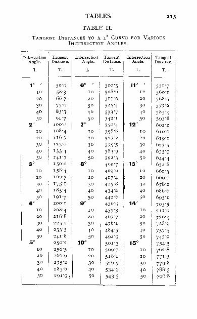
I
TABLES 215
TABLE II.
TANGENT DISTANCES TO A 1° CURVE FOR VARIOUS INTERSECTION ANGLES,
Intersection Tangent Intersection Tangent Intersection Tangent Angle. Distance. Angle, Distance. Angle, Distance,
I. T, I. T, I. T,
I ---
1° I 50 '0 6° I
3°0 '3 11° I
55 1 '7 10 58'3 10 308 '6 10 560 '1 20 66'7 20 317'0 20 568 '5 3° 75'0 3° 32 5'4 30 577'° 4° 83'3 40 333'7 4° 585'4 5° 91 '7 50 342'1 50 593'8
2° 100'0 7° 350 '4 12° 602'2 10 108'4 10 358 '8 10 610'6 20 II6'7 20 367'2 20 619'1 3° 125'0 3° 375'5 30 627'5 40 133'4 40 383'9 40 635'9 5° 141'7 50 392'3 50 644'4
3° 150 '0 8° 400 '7 13° 652 '8 10 158 '4 10 4°9'0 10 661'3 20 166'7 20 417'4 20 669'7 3° 175'1 30 425'8 3° 678 '2 4° 183'4 40 434'2 40 686'6 5° 191'7 50 442 '6 50 695'1
4° 200'1 go 450 '9 14° 7°3'5 10 208'4 10 459'3 10 712 '0 20 216'8 20 467'7 20 720'4 3° 225'1 30 476 '1 30 728 '9 4° 233'5 40 484'5 40 737'4 50 241'8 50 492 '9 50 745'9
5° 25 0'2 10° 501 '3 15° 754'3 10 258 '5 10 5°9'7 10 762 '8 20 266'9 20 518 '1 20 771 '3 3° 275'2 3° 526'5 30 779'8 4° 283'6 4° 53-1-'9 40 788 '3 50 291 '9 ~ 5° 543'3 50 796 '8

216 FIELD ENGINEER'S HANDBOOK
Table H.-continued.
,"_,mol Tangent Intersection Tangent II Intersection Tangent Angle, Distance. Angle. Distance. Angle. Distance.
I. T. I. T. I I. T.
16° 1 80Y3 21° 1 1061 '9
I 26° 1 1322 '8
10 81 3'8 10 1°7°"5 10 1331 '6
20 822"3 20 1°79'2 i 20 1340 "4
30 83°'8 3° 1087"8 i 3° 1349'2
40 839'3 40 1096 '4 40 1358 '0
50 847"8 50 IIOYl i 50 1366 "8
17° 85 6 '3 22° 1 II 3"7 I 27° 137y6
10 864"8 10 1122'4 I 10 I384 "4
20 873"4 20 1131 '0 20 1393 "Z
3° 881 "9 30 II39'7 30 1402 "0
40 89°'4 40 1148 "4 40 1410 '9
5° 899'0 5° II57"° 50 1419"7
18° 9°7"5 23° II65 "7 28° 1428 "6
10 916"0 10 1174'4 10 1437"4
20 924"6 20 II83 "I 20 1446 '3
30 933"1 3° II91 '8 30 1455"1
40 941 "7 4° 1Z00"5 40 1464'0
50 95°'3 5° lZ09'2 50 1472"9
19° 95 8 '8 24° 1217"9 29° 1481 "8
10 967"4 10 1226"6 10 1490 "7
20 976 '0 20 1z35 '3 zo 1499'6
I 30 984'5 3° 1244'0 30 15°8'5
4° 993'1 40 1252 "8 40 1517"4
50 1001 '7 50 1261'5 50 1526 '3
20° 1010"3 25° 127°'2 30° 1535'3
10 i 1018'9 10 1279'0 i 10 1544"2
20 1027'5 20 1287"7 20 1553'1
3° 1°36 '1 30 1296 '5 30 1562 '1
40 1°44'7 40 1305"3 40 1571 "0
50 1053 '3 50 1314"0 50 1580 '0
I
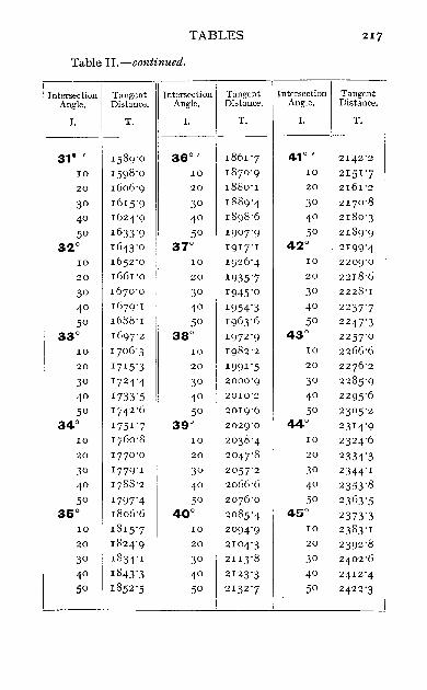
TABLES 217
Table n,-continued,
i Intersection Tangent Intersection Tangent Intersection Tangent
Angle, Distance. Angle, Distance. Angle, Distance,
I. T, 1. T, 1. T,
31° , I589'O 36° , I86I '7 41° , 2I42'2
10 I598 'O 10 IS70'9 IO 2 I 5 I '7 20 I606'9 20 I8So'I 20 2161'2
30 1615"9 I 30 IS89'4 30 2170'S
40 1624'9
I
40 IS9S'6 40 21S0'3
50 I633'<) 50 I907'9 50 2IS9'9
32° I643'O 37° 1917'1 42° 21 99'4 10 I652'o
I
10 I926'4 10 2209'0
20 1661'0 20 1935'7 20 221S'6
30 1670 '0 30 I945"0 30 222S'1
40 1679'1 40 1954'3 40 2237'7 50 1688'I 50 J963'6 50 2247'3
33° I697'2 38° 1972 '9 43° 2257'0 10 1706 '3 IO 1982'2 10 2266'6 20 1715"3 20 1991 '5 20 2276 '2
30 1724 '4 30 2000'9 30 22S5"9
40 1733'S 40 2010'2 40 2295'6
50 1742 '6 50 20I9'6 50 2305"2 34° I75 1 '7 I 39° 2029'0 44° 23 14'9
10 1760'8 10 2038 '4 10 23 24'6 20 1770 '0 20 2047'8 20 2334'3 30 1779'I 30 2057'2 30 2344'1
40 1788 '2 40 2066'6 40 2353 '8
5° 1797' 4 5° 2076 '0 50 23 63'5 35° 1806'6 40° 2085'4 45° 2373 '3
10 181 5'7 10 2094'9 I 10 23 83'1 20 1824'9 20 2104'3 20 2392 '8
30 1834'1 30 21 13'8 30 2402 '6
40 1843'3 40 212 3 '3 40 2412'4 50 1852'S 50 21 32 '7 50 2422'3
I

218 FIELD ENGINEER'S HANDBOOK
Table H.-continued.
I I Intersection Tangent I Intersection rangent Intersection Tangent
Angle. Distance.
I
Angle. Distance. Angle. Distance.
I. T. r. T. I. T.
---"
46° , 2432 ·1 51°
, 2732 .9 56°
, 3°46 .5
10 2441.9 10 2743.1 10 305]"2 20 245 1.8 20 2753·4 20 3067"9 30 246 1"7 30 2763"7 30 3°78 .7
! 40 2471 ·5 4° 2773 ·9 40 3°89·4 , , 50 2481 ·4 50 2784.2 50 3100.2
47° 2491 .3 i 52° 2794·5 57° 3 II O·9 10 25°1·2 10 28°4·9 10 3121 .7 20 2SIl·2 20 2815"2 20 3132 .6 30 2521 ·1 30 2825"6 30 3143·4 40 2531 ·1 40 2835"9 40 3154.2 50 2541 ·0 50 2846 .3 5° 3165"1
48° 255 1.0 53° 28 56 .7 58° 3176 .0 10 2561 ·0 10 286]"1 10 3186.9 20 2571 ·0 20 28 77"5 20 3197"8 30 2581 ·0 3° 2888·0 30 3208 .8
40 2591 ·1 40 2898 .4 40 321 9.7 50 2601·1 50 29°8·9 50 323°.7
49° 261 1·2 54° 2919.4 59° 3241.7 10 2621·2 10 2929.9 10 3252.7 20 2631 ·3 20 294°·4 20 3263.7
30 2641"4 30 2951"0 3° 3274.8
40 2651 ·5 40 2961 ·5 40 3285"8 50 2661 ·6 50 2972 ·1 50 3296 .9
50° 2671 ·8 55° 2982 .7 60° 33°8·0 10 2681 ·9 10 2993·3 10 33 19.1 20 2692.1 20 3°03·9 20 3330 .3 30 27°2·3 30 3°14·5 30 3341.4
40 2712 ·5
I
40 3025"2 40 3352·6 50 2722 ·7 50 3°35.8 50 3363.8
I I I

TABLES 219
Table Ho-continuedo
Intersection Tangent Intersection Tangent Intersection Tangent Angleo Distance. Angleo Distance. Angle. Distanceo
1. To I. To 1. To
61° I 3375°0 66° I 3720°9 71° I 4°86°9 10 3386 °3 10 3732 °7 10 4099°5 20 3397"5 20 3744°6 20 4II2°J. 30 340808 30 3756 °5 30 4124°8 40 3420 °1 40 3768 °5 40 4137"4 50 3431 °4 50 3780°4 50 4150 °1
62° 3442 °7 67° 3792 °4 72 c 4162°8 10 3454°1 10 3804°4 10 4 175"G 20 3465°4 20 3816 °4 20 4188 °5 30 3476 °8 30 3828 °4 30 4201 °2 40 3488 °2 4° 384°°5 40 421 4°0 50 3499°7 5° 3852°6 50 422608
63° 35II °1 68° 3864°7 73° 4239°7 10 3522°6 10 3876 °8 10 4252 °6 20 3534°1 20 3889°0 20 4265"6 30 3545°6 30 3901°2 30 4278 °5 40 3557"2 40 3913°4 40 4291 °5 50 3568 °7 50 3925°6 60 43°4°6
64° 3580°3 69° 3937"9 74° 4317"6 10 3591°9 10 3950 °2 10 4330 °7 20 3603°5 20 3962 °5 20 4343°8 30 361 5"1 30 3974°8 30 4356°9 40 362608 40 3987"2 40 4370°1 50 3638 °5 50 3999°5 50 4383°3
65° 3650°2 70° 40u oy 76° 4396°5 10 3661 °9 10 4024°4 10 4409°8 20 3673°7 20 403608 20 442 3°1 30 3685"4 3° 4049°3 30 4436 °4 40 3697"2 40 4061°8 40 4449°7 50 37°9°0 5° 4074°4 50 4463°1

220 FIELD ENGINEER'S HANDBOOK
Table II -continued,
Intersection I Tangent Angle, ,Distance,
I Intersection I Tangent i Angle. Distance.
I, I T, 1. T,
76° , I 4476 '5 81° , 4893'6 I 10 I 4489'9 10 4908 '0
20 45°3'4 20 I 4922 '5
30 45 16 '9 30 4931'0 40 4530 '4 4° 495 1 '5 50 4544'0 50
I
4966'1 77° 4557'0 82° 4980 '7
10 4571 '2 10 4995'4 20 458,~ '8 20 5010 '0 30 4598 '5 3°
! 5024'8
40 4612 '2 40 5039'5 50 4(n6'o 5° 5°54'3
78° 4639'8 83° 5069'2 10 4653'6 10 5 084'0 20 4661'4
I
20 5099'0 30 4681 '3 3° 5 II3'9 40 4695'2 4° 5128'9 50 47°9'2 50 5143'9
79° 4723'2 84° 5159'0 10 4731'2 10 5174'1 20
I
4751 '2 20 5189'3 30 4765'3 3° 52°4'4 40 4779'4 40 521 9'7 50 4793 '6 5° 5234'9
80° 4801'7 85° 5250 '3 10 4822 '0 10 5265'6 20 4836 '2 20 5281 '0
30 4850 '5 3° 5296 '4
40 4864'8 40 53II'9
50 4879'2 50 5321'4
I I
I I
I
Intersection I Tangent Angle, I Distance,
1. I T,
86° ,
10 20
3° 40
5° 87°
10 20
3°
4° 50
88° 10 20
30
4° 5°
89° 10 20
3° 4° 5°
90 10 20
3° 4° 5°
I I
5343 '0 5358 '6 I 5374'2 5389'9 54°5'0 5421 '4 5431'2 5453'1 5469'0
5484'9 5500 '9
551 1'° 5533 'I 5549'2 55 65'4 5581 '6
5591'8 561 4'2
5630 '5 5646 '9 5663'4 5679'9 5696 '4 I 5713 '0
5729'7 5746 '3 5763 'I
5779'9 5796 '7 5813 '6
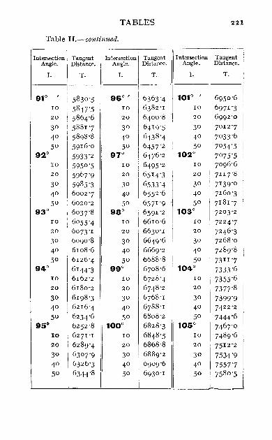
TABLES 221
Table H"-continued"
Intersection Tangent Intersection Tangent Intersection I Tangent Angle" Distance"
I
Angle" Distance" Angle" Distance"
I" T" I. T" I" T"
91° ,
5830 "5 96° 1 6363"4 1010 I 6950 "6 10 5847"5 10 6382 "1 10 6971 "3 20 5864"6 20 6400 "8 20 6992"0 30 5881 "7 3° 6419"5 3° 7°12 "7 40 5898"8 4° 6438 "4 4° 7033"6 50 5916"0 50 6457"2 50 7°54"5
920 5933"2 970 6476 "2 1020 7°75"5 10 5950 "5 10 6495"2 10 7096 "6 20 5967"9 20 6514"3 20 711 7"8 30 5985"3 30 6533"4 3° 7139"0
4° 6002"7 4° 6552 "6 40 7160"3
5° 6020"2 50 6571 "9 50 7181 "7 930 6°37"8 980 6591 "2 103° 72°3"2
10 6055"4 10 6610"6 10 7224"7 20 6073"1 20 6630 "1 20 7246 "3 30 6090"8 30 6649"6 3° 7268 "0
4° 6108"6 40 6669"2 4° 7289"8
5° 6126"4 50 6688"8 50 73II "7 94° 6144"3 990 6708 "6 1040 7333"6
10 6162"2 10 6728 "4 10 7355"6 20 6180"2 20 6748 "2 20 7377"8 30 6198"3 30 6768 "1 30 7399"9 40 6216"4 40 6788 "1 40 7422"2
5° 6234"6 50 6808"2 5° 7444"6 950
\6252"8 1000 6828"3 1050 7467"0 10 6271 "I 10 6848 "5 10 7489"6 20 6289"4 20 6868"8 20 7512 "2 30 63°7"9 30 6889"2 30 7534"9 40 6326"3 4° 6909"6 40 7557"7 50 6344"8 50 6930 "1 50 7580 "5
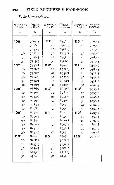
222 FIELD ENGINEER'S HANDBOOK
Table n,-continued,
Intersection Tangent Intersection Tangent 1 Intersection I Tangent Angle, Distance. Angle, Distance. Angle, ' Distance,
1. T, I. T, I. T.
106° I 7603'5 111° I 8336 '7 116° I 9169'4 10 7626 '6 I 10 8362 '7 i 10 9199'1 20 7649'7 20 83 88 '9 20 9229'0
30 76 72 '9 30 8,41 5'1 30 9259'0
40 7696 '3 40 8441 '5 40 9289'2 50 7719'7 50 8468 '0 50 93 19'5
1070 7743'2 112° 8494'6 117° 9349'9 10 7766 '8 10 8521 '3 10 93 80 '5 20 7790 '5 20 8548 '1 20 9411'3
30 7814'3 30 8575'0 30 9442'2
40 7838 '1 40 8602'1 40 9473'2 50 7862 '1 50 862 9'3 50 9504'4
108° 7886 '2 113° 8656 '6 118° 9535'7 10 7910 '4 10 8684'0 10 9567'2 20 7934'6 20 8711 '5 20 9598 '9 30 7959'0 30 8739'2 30 9630 '7 40 7983'4 40 8767'0 40 9662 '6 50 8008'0 50 8794'9 50 969+'7
109° 8032 '7 114° 8822 '9 119° 972 7'0 10 8057'4 10 8851 '0 10 9759'4 20 8082 '3 20 8879'3 20 9792 '0
30 8107'3 30 890 7'7 30 982.,'8
40 81 32 '3 40 893 6 '3 40 9857'7 50 81 57'5 50 8965'0 50 9890 '8
110° 8182 '8 115° 8993'8 120° 9924'0 10 8208'2 10 9022 '7 20 8233'7 20 9051 '7
30 8259'3 30 9080 '9
40 8285'0 40 9Ilo'3
50 83 10 '8 50 9139'8
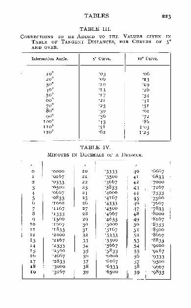
TABLES
TABLE III. CORRECTIONS TO BE ADDED TO THE VALUES GIVEN IN
TABLE OF TANGENT DISTANCES, FOR CURVES OF 50 AND OVER.
Intersection Angle. SO Curve. 10° Curve.
100 '°3 '06 20° '06 '13 300 '10 '19 400 '13 '26 SOo '17 '34 600 'ZI '42 7°0 '2S 'SI 800 '3° '61 goa '36 "72
1000 '43 '86 110° '5 1 1'°3 1200 '62 1'25
TABLE IV.
MINUTES IN DECIMALS OF A DEGREE. -~.--~ ~~---
, !
° '0000 20 '3333 4° '6667 I '0167 21 '3s00 41 '6833 2 '°333 22 '3 667 42 '7°00 3 '°5°0 23 '3833 43 '7167 4 '0667 24 '4°00 44 "7333 S '0833 2S '4167 4S '7s00 0 '1000 20 '4333 46 "7667 7 ' lI67 27 '4500 47 '7833 8 '1333 28 '4667 48 '8000 9 'ISOO 29 '4833 49 '8167
10 '1667 30 'Sooo SO '8333 II '1833 31 'S I67 51 '85°0 12 '2000 32 'S333 S2 '8667 13 'z167 33 'SSOO S3 '8833 14 '2333 34 '5667 S4 '9°00 IS '2S00 3S '5 833 SS '9167 10 'z667 36 '6000 S6 '9333 17 '2833 37 '6167 S7 '9s00 18 '3°00 38 '6333 58 '9667 19 '3167 39 '6soo
I S9 '9833
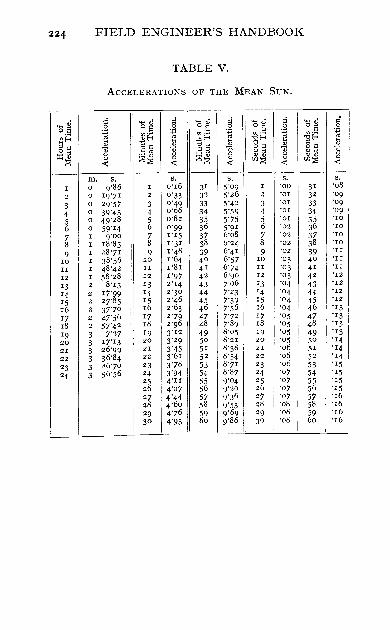
224 FIELD ENGINEER'S HANDBOOK
TABLE V,
ACCELERATIONS OF THE MEAN SUN,
I
I I
c;~ g o~ ci 'O~ d o~ ci ~ , " I :§ 0 ~ ~,§ 0
U)~ ~ ~'~ £~ ~ ~,~ 'p
I $f-< E §~ ::: 'Of-< '" El~ i I;j §~ lil
,,~ "il ~~ 1l ~ ]1 0", ~ '" " '" ,,'" ;J::E " :@:E <3 " " " " "" «: «: «: (I):;;; «: (I):;;;
---- -- --' -- . -- --m, s, s, s, s, S,
I 0 9'86 ! I 0'16 31 5'09 I '00 31 '08 I
2 0 19'71
I
2 0'33 32
I
5'26 2 'or 32 "09
3 0 29'57 3 0"49 33 5'42 3 "01 33 '09
4 ° 39"43 i
4 0'66 34 5'59 4 "or I 34 '09
5 0 49"28 5 0"82 35 I 5'75 5 'or
I 35 "'0
6 0 59'r4 i
6 0"99 36 5'9 ' 6 '02 36 "ro
7 I g'oo 7 1'15 37 6'08 7 "02 37 "ro
8 1 r8'85 8 1'31 38 6"24 8 '02 38 "'0
9 I 1 28"71 9 1"48 39 6'4 1 I 9 "02 39 "II
ro I 38'56 ro 1"64 40 6"57 : ro '03 40 'II
II I 48"42 II r8r 4' 6'74 II '03 4' 'II
12 I 58'28 12 1"97 42 6'90 12 "03 42 '12
13 2 8'13 13 2'r4 43 1'06 13 '04 43 '12
14 2 17'99 '4 2'30 ! 44 7"23 14 '04 44 '12
IS 2 27"85 IS 2"46 45 7"39 IS "04 45 '12
16 2 37'70 16 2"63 46 1'56 16 "04 46 '13
17 2 41'56 17 2"79 47 7"72
i 17 "aS 47 '13
18 2 57"42 18 2"96 48 1'89 18 "OS 48 "13
19 3 1'27 19 3'12 49 8"05 "9 "05 49 '13 20 3 17'13 20 3'29 50 8'21 20 "aS 50 "14 21 I 3 26"99 21 3"45 51 8'38 21 '06 51 "14 22 3 36"84 22 3'61 52 8'54 22 "06 52 "14
23 I 3 46'70 23 3'78 53 8"71 23 "06 53 i "15
24 3 56'56 24 3'94 54 8'87 24 "07 54 '15 25 4"II 55 9"04 25 "07 55 '15 26 4'27 56 g'20 26 '07 56 '15 27 4'44 57 9'36 27 '07 57 "16 28 4'60 58 9"53 28 "08
I 58 "16
29 4"76 59 9"69 29 "08 59 '16 30 4"93 , 60 9"86 30 "08 60 '16
I .1

INDEX
ABBREVIATIONS, 199 Acceleration, 156, 223 Acre, 2 Alignment, re-rJnning, 109 Altitude, 164 Anallatic lens, 144 Aneroid,68 Apparent noon, 160 ---- sun, 160 Aries, 153 Axemen,7 I Azimuth, 173
BACK flagman, 72 Backsight, 36 Barometer pressure, 165 Bearing, 42, 43, 173 Bench marks, 35 Borrow pits, 138
CAMPING-GROUND, 109 Celestial equator, 153, 154 --- pole, 153 Centrifugal force, 93-5 Chain, Gunter, 1 --- steel tape, 3 -- surveying, 30-4 Chaining, 2, 3 Check levels, lIO
Circum-polar stars, 190-4 Clearing, lIO Clock, astronomical, 155 ---, common, 154, 155 ---, mean time, 155 Collimation, 6 Compass, 21, 26, 28 Connaissance des Temps,
188, 189 Construction, 108-40 Convergence, 173, 174 Correction line, 206 Correction of traverse, 53-7 Cross-hairs, 6, 26, 27 ----- (illuminating),
195 Crossings, 138, 139 Cross-sectioning, II2-21 Cubic parabola, 103-7 Culmination, 167 Culverts, 138 Curvature of earth, 41
DAY, 154 Declination, 47, 153, 160 Deflection angles, 46 Degree of curve, 59 Departure, 51 Diagonal eye-piece, 194 Diaphragms, 26, 27

226
Ditches, 139 Double centering, 50, III Dumpy level, 5-8
EARTHWORK, 126-40 Elongation, 190-2 Equation of time, 160
FACE left, 21 ---, reversing, 21 --- right, 21 First point of Aries, 153 Fixed stars, 153 Follower, 2 Foresight, 36
GENERATING number, 146 Geodetic surveying, 30 Grade, II2 --- plugs, II9 ---- staff, II5-21 Grades, final, 140 ---, second, 139 Grubbing, IIO
HAND level, 12, 77, 78 Haul, 133-7 Head-chainman, 2, 72 Hour angle, 158 Hubs, 21 --, referencing, 1 I I
ILLUMINATING cross-hairs, 195
Index error, 164 Instrumentman, 72
INDEX
LATITUDE, 51, 153, 167-70 formulae, 209
Leader, 2 Leveller, 74 Levelling, 35-41, 74-8 ----, checks in, 37-40 ---- screws, 21 Local sidereal time, 156, 186 Location, 67, 79-92 Locke hand level, 12, 77, 78 Long chord, 65, 87 Longitude, 153, 183
MAGNETIC declination, 47 Mean noon, 160 --solar year, 154 --- sun, 154, 156 --- time, 155 Miner's dial, 68 Multiplying constant, 143-
146
'NAUTICAL ALMANAC,' 154, 163
Nautical bearing, 42 Night lights, 194 Noon, 154 North Star, 185-<;1
ORION, 164 Overhaul, 133-7
PARALLAX, 7 - (astronomical),
165, 166 Plane surveying, 30 Planets, 197
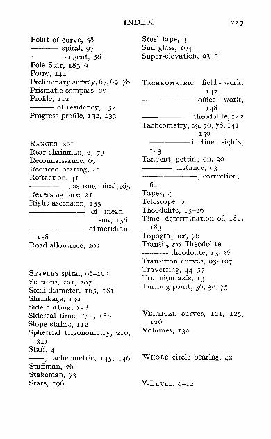
INDEX 227
Point of curve, 58 --- spiral, 97 ---- tangent, 58 Pole Star, 185-9 Porro, 144 Preliminary survey, 67, 69-78 Prismatic compass, 26 Profile, II2
--- of residency, 132 Progress profile, 132, 133
RANGES, 201 Rear-chainman, 2, 73 Reconnaissance, 67 Reduced bearing, 42 Refraction, 41 -----, astronomical, 165 Reversing face, 21 Right ascension, 153
158
of mean sun, 156
of meridian,
Road allowance, 202
SEARLES spiral, 96-103 Sections, 201, 207 Semi-diameter, 165, 181 Shrinkage, 139 Side cutting, 138 Sidereal time, 156, 186 Slope stakes, II2
Spherical trigonometry, 210, 2II
Staff, 4 --, tacheometric, 145, 146 Staffman, 76 Stakeman, 73 Stars, 196
Steel tape, 3 Sun glass, 194 Super-elevation, 93-5
TACHEOMETR1C field - work, 147
office - work, 148
-------theodolite, 142 Tacheometry, 69, 70, 78, 141-
150 ------ inclined sights,
143 Tangent, getting on, 90 ---- distance, 63
-----, correction, 64
Tapes, 4 Telescope, 6 Theodolite, 13-26 Time, determination of, 182,
183 Topographer, 76 Transit, see Theodolite ---- theodolite, 13-26 Transition curves, 93-107 Traversing, 44-57 Trunnion axis, 13 Turning point, 36, 38, 75
VERTICAL curves, 121, 125, 126
Volumes, 130
WHOLE circle bearing, 42
V-LEVEL, 9-12

PRINTED BY
SPOTTISWOODE AND CO. LTD., COLCHESTER
LONDON AND ETON

A Valuable Table-book for Surveyors, Mining and Civil Engineers
TRAVERSE TABLES WITH AN INTRODUCTORY CHAPTER ON
CO-ORDINATE SURVEYING
BY
HENRY LOUIS, M.A., D.Se., A.R.S.M. ~I.INST.C.E., F.I.C., F.G.S., ETC.
PROFESSOR OF MINING AND LECTURER O~ SURVEYING, ARMSTRONG COLLEGE, NEWCASTLE-ON"-TYNE
A:-iD
GEORGE WILLIAM CAUNT, M.A. LECTURER IN MATHE~IATICS. ARMSTRONG COLLEGE, NEWGASTLE-ON-TYNE
SECOND EDITION. xxxii + 90 pages. Demy Bvo., flexible cloth, rounded corners, 4s. 6d. net (inland postage 3d.)
THE publication of this little work is due to the writer's conviction, gained in many years of miscellaneous surveying practice, as well as in some spent in the teaching of surveying, that the co-ordinate method of plotting traverses is far preferable to any other, on the score of both accuracy and expedition.
The arrangement of the tables is one which the writer finds in practice to be convenient for rapid work, all the figures needed for any given angle being found in one opening of the pages and in one line. The tables have been entirely recalculated by Mr. Caunt, and checked in all possible ways, and every precaution has been taken to ensure accuracy in printing.
London: EDWARD ARNOLD.
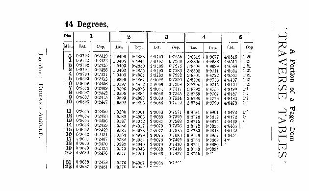
l' o ~ PO ~
trI I t)
~ :;: t)
> :;: :% o r t)
14 Degrees. DiBI. 1
Min. Lat. Dep. r-- --- ---
0 0'9703 O'2H9 1 O'970~ 0'~422 2 0'9702 0'2425 3 0'9701 0'2428 4 0'9/00 0'2431 5 0'9699 0'2433 6 0'9099 0'2436 7 0'9698 0'2439 8 0'9087 0'2442 9 0'8697 0'2445
10 0'9696 0'2447
11 0'9695 0'2450 12 0'%9-1 0'2453 13 0'9694 0'2456 14 0'%93 0'2459 15 O'9W2 0'2462 16 0'9692 O'24G4 17 U'%.I1 0'2467 18 0'9090 0'2470 19 0'%89 0'2473 20 0'9689 0'2476
21 0'9688 0'2478 22 0'9687 0'2481
2
Lat. Dep. -----
1'9406 0'4838 1'9405 O'48.J4 1'9403 0'4850 1'9402 0'4855 1'9400 0'4861 1'9399 0'4867 1'9397 0'4872 1'9396 0'4878 1'9395 0'4884 1'9393 0'4889 1'9il92 O'489ii
1'9390 0'4901 1'9389 0'4906 1'9il~7 0'4912 1'9386 0'4917 ['9385 0'4923 1'9il83 0'4929 ['9H82 0'4931 1'~)380 0'4940 1'9379 0'4946 1'9677 0'4951
l'9il,6 0'4957 l'9:l7fi O·.ia~~
3 4 5 ~ Lat. Dep. Lat. Dep. Lat. Dep
---I---- --------2'9109 0'7258 3'8812 0'9677 4'8515 1'20 2'9107 O'72G6 3'8809 0'9688 4'8511 1'21 2'9105 0'7275 3'8806 0'9699 4'8508 1'21 2'9103 0'7283 3'8803 0'9711 4'8504 1'21 2'9100 0'7292 3'8801 0'9722 4'8501 1'21 2'9098 0'7300 3'8798 0'9733 4'8497 1'21 2'90% 0'7308 3'8795 0'9745 4'8494 1'2.1 2'9094 0'7317 3'8792 0'9756 4'8490 1'-;
~ ~)o
<>u tTj§. ~ g' (J)O
2'9092 0'7325 3'8789 O'97G7 4'8487 l"z 2'9090 0'7334 3'S786 0'9778 4'8483 1'~ 2'9088 0'7312 3'8784 0'9790 4'8479 I"
tTj-' ~
2'9086 0'7351 3'8781 0'9801 4'8476 1'~ 2'9083 O'73h9 3'8778 0'9812 4'8472 l' 2'9081 0'7368 0'8775 0'9824 4'8469 1
2'9079 0'7376 3'8772 0'9835 4'8465 2'9077 0'7385 3'8769 0'9846 4'8462 2'9075 0'7393 3'8766 0'9857 4'84~' 2'9073 0'7402 3'8764 0'9869 4'"
~;;,t' ~~ td::;-~8
2'9070 0'7410 3'87Gl 0'9880 2'9068 0'7418 g'8758 0'989' tTj 2'9066 0'7427 3'S755 o,e- (J) 2'9064 0'7,,0-o.",..~

LOUIS & CAUNT'S
TRAVERSE T ABI-IES
SOME PRESS OPINIONS
Jlining Journal :-' It is now generally recognised that for plotting
mine surveys the co-ordinate method is far preferable to any other on the
score of accuracy and expedition. The requisite resolution of tIaverses can be effected by calculation with the aid of natural sines and cosines, of loga
rithmic sines and cosines, or of the slide rule. \Vith traverse tables, which
show by inspection the amount of latitude and departure for any bearing and
distance. calculations may be dispensed vdth. In order to be of any use to the mine surveyor such tables must, on the authority of Brough's" Mine
Surveying," be computed for every minute of bearing and to four places of
decimals. These conditions are fulfilled by the admirable. compact, and
inexpensive tables compiled by Professor Henry Louis and Mr. G. W. Caunt.
They are just \vhat is required by the mining student and by the practical
mine surveyor. They are calculated for every minute of bearing to five significant places, and are so arranged that all the figures needed for any
given angle are found at one opening of the pages and in ODe line. We have
carefully tested the figures, and find that every precaution has been taken to
ensure accuracy in printing,'
Professor LE NEVE FOSTER, Royal College of Science. London :-' I feel
sure that the book will prove useful to many of the students here. t
Mining Engineering ;-' The book is an excellent one, and it is published
at a very low rate.'
Eugineering and JIi1ting Journal :-' The opening chapter is a clear and compact explanation of the methods of co-ordinate surveying. Professor
Louis has had much experience in actual surveying, both surface and under
ground, and also in teaching surveying to others: the result being that he understands very clearly what the surveyor needs.'
London: EDWARD ARNOLD.
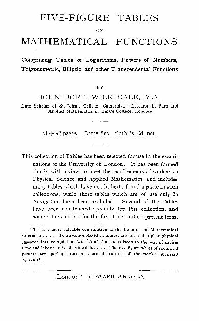
FIVE-FIGURE TABLES OF
MATHEMATICAL FUNCTIONS
Comprising Tables of Logarithms, Powers of Numbers,
Trigonometric, Elliptic, and other Transcendental Functions
BY
JOHN BORTHWICK DALE, M.A. Late Scholar of St. John's College. Cambridge; Lecturer in Pure and
Applied Mathematics in King's Coll~ge. London.
vi + 92 pages. Demy 8vo., cloth 3s. 6d. net.
This collection of Tables has been selected for use in the exami
nations of the University of London. It has been formed
chiefly with a view to meet the requirements of workers in
Physical Science and Applied Mathematics, and includes
many tables which have not hitherto found a place in such
collections, while those tables which are of use only in
Navigation have been excluded. Several of the Tables
have been constructed specially for this collection, and
some others appear for the first time in their present form .
. This is a most valuable contribution to the literature of Mathematical reference. . .. To anyone engaged in almost any form of higher physical research this compilation will be an enormous boon in the way of saving time and labour and collecting data. . .. The five-figure tables of roots and powers are. perhaps, the most useful features of the work. '-Mining
Journal.
-------- -----London: EDWARD ARNOLD.