the future of coal andrew maxson and david thimsen
TRANSCRIPT

46 ieee power & energy magazine may/june 20131540-7977/13/$31.00©2013IEEE
Digital Object Identifier 10.1109/MPE.2013.2245580
Date of publication: 17 April 2013
©ARTVILLE, LLC., PHOTODISC
The Future of CoalAndrew Maxson and David Thimsen
11mpe03-maxson-2245580.indd 46 04/04/13 3:04 PM

may/june 2013 ieee power & energy magazine 47
Digital Object Identifier 10.1109/MPE.2013.2245580
Date of publication: 17 April 2013
C
Confronting Environmental Challenges That Threaten Its Use
COAL-FIRED POWER PLANTS CURRENTLY SUPPLY NEARLY HALFthe electricity consumed worldwide. Globally, coal continues to be the primary fuel for affordable and reliable electric power production, due to its low cost and because many countries have indigenous coal resources, providing energy independence.
However, the continued use of coal to fuel electric power generation is con-fronted by environmental/economic challenges that, in some regions, are threaten-ing to reduce or eliminate its use. Coal power’s major contribution to increasing carbon dioxide (CO2) concentrations in the atmosphere that could result in global climate change poses a new challenge.
While solutions are possible, much is unknown or untested. Meeting the envi-ronmental challenges of coal will require improvements in existing technologies and the development of new breakthrough technologies.
To capitalize on coal’s advantages and help mitigate its environmental chal-lenges, the following key R&D goals need to be accomplished:
✔ improve power plant efficiency to reduce the amount of coal used✔ improve emissions control, producing near-zero emissions (NZEs) of all
conventional pollutants✔ implement cost-effective, environmentally acceptable, scalable technolo-
gies to capture and permanently store CO2 produced by coal-fired power plants.
Coal Power SystemsAt a high level, coal power systems can be broken into two principal forms: com-bustion and gasifi cation.
CombustionCombustion-based coal power plants burn coal in solid form to produce thermal energy. A primary example is pulverized coal (PC) power plants, the most preva-lent type, worldwide, for coal-based generation. Coal is ground to the consistency of fl our by mills and blown into a furnace where combustion takes place with air, and heat is transferred to steam that, in turn, is passed to the steam turbine to produce power. A block fl ow diagram of a PC system with associated air quality control system (AQCS) components is shown in Figure 1.
Equipment in the AQCS is designed to control coal-related emissions includ-ing the following:
✔ mercury, produced from coal-bound mercury and controlled by activated carbon injection (ACI) with the subsequent capture of the carbon particles
✔ nitrogen oxides (NOX), produced from coal-bound nitrogen and from the nitrogen in the air at high flame temperatures and controlled by staged combustion to keep flame temperatures low and selective catalytic reduc-tion (SCR) to destroy NOX produced
✔ particulate matter (PM), produced largely from coal ash but also from SO3
in the flue gas and controlled by electrostatic precipitators (ESPs) or fabric filter bag houses
✔ sulfur oxides (SOX), produced from coal-bound sulfur and controlled by flue gas desulfurization (FGD).
Another type of combustion-based coal power plant is fl uidized bed combus-tion (FBC). Crushed coal is burned in a bed of hot sorbent particles suspended in motion by rising combustion air. The chief benefi ts of FBC technology are the capture of sulfur by the sorbent bed, the reduced NOX production at the rela-tively low temperatures, and its ability to burn almost any combustible material as fuel.
Steam power cycles employed by PC and FBC power plants are commonly categorized by the following steam conditions:
11mpe03-maxson-2245580.indd 47 04/04/13 3:04 PM

48 ieee power & energy magazine may/june 2013
✔ Subcritical cycles have a steam pressure that is below the critical point of water. The steam conditions used in subcritical units are up to 180 bar/541 °C.
✔ Supercritical (SC) cycles became fully commercial in coal plants in the early 1960s. SC cycles typically have steam pressures of 240 bar or higher and steam tem-peratures around 565 °C.
✔ Ultra-supercritical (USC) cycles have steam tempera-tures around 600 °C and steam pressures greater than 300 bar. While not common, these plants represent the highest efficiency PC plants available today [up to 42% (note that all efficiencies given in this article are on a net, higher heating value, basis)].
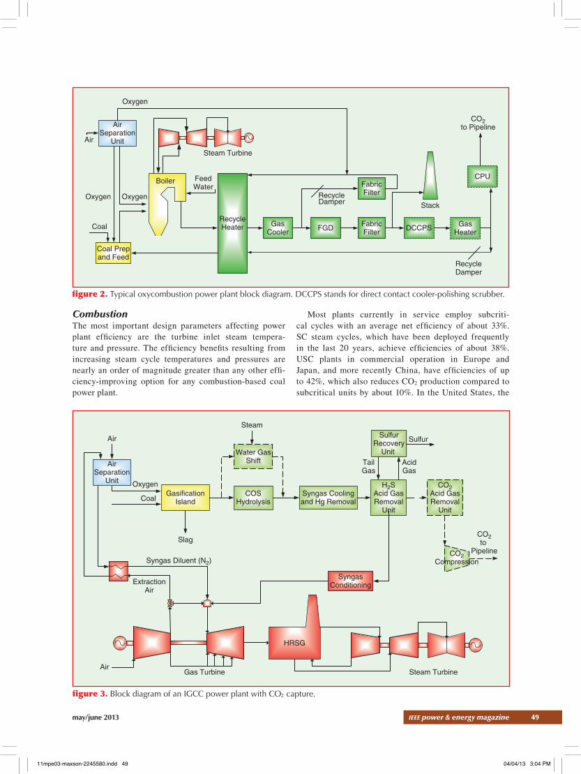
The potential requirement to limit CO2 emissions from coal has brought forth the development of another combus-tion-based coal power system: oxycombustion. Oxycom-bustion is the combustion of pulverized coal with oxygen separated from the air, resulting in a flue gas that is predomi-nantly CO2 and water vapor, greatly simplifying the capture and removal of CO2. An oxycombustion power plant has many similarities to an air-fired power plant; the fuel han-dling systems, steam cycles, and other balance of plant sys-tems will be nearly identical to their air-fired counterparts.
Figure 2 is a block diagram for a typical oxycombustion power plant. Systems unique to an oxycombustion plant include:
✔ an air separation unit (ASU) removes nitrogen and other trace gases from the air by liquefaction and cryogenic distillation to produce a stream of oxygen
✔ a CO2 purification unit (CPU) includes a flue gas dry-ing system and compressors to deliver the CO2 to a receiving pipeline or geological storage site. It could
also include a cryogenic partial condensation process to clean the CO2 of impurities.
GasificationIntegrated gasification combined cycle (IGCC) power plants gasify coal in a gasifier producing a “syngas,” which then fuels a high-efficiency combustion turbine combined cycle power plant. The hot, raw syngas consists primarily of carbon monoxide (CO), CO2, hydrogen, water, methane, reduced sulfur compounds, nitrogen, and argon.
After the syngas is cooled, the mercury is removed by adsorption on activated carbon. Hydrogen sulfide and CO2 are then removed in an acid gas removal (AGR) step. By cleaning the pressurized syngas prior to combustion, IGCC plants can meet extremely stringent air emission standards.
The clean syngas fuels the gas turbine. The hot exhaust from the gas turbine passes to a heat recovery steam genera-tor (HRSG) where it produces steam that drives a steam tur-bine. A block diagram of a typical oxygen-fired IGCC system with precombustion CO2 capture is shown in Figure 3.
Improving EfficiencyImproving the thermodynamic efficiency of coal power plants is a key part of any strategy to make coal generation more viable in the future. Increased efficiency not only pro-vides fuel cost savings but it reduces all emissions per unit of plant output, in particular CO2 emissions (a nine percentage point efficiency gain results in a 20% reduction in CO2 emis-sions). Higher-efficiency plants can also have better part-load operation and operating flexibility, cutting balance-of-plant costs, due to reduced size, water consumption, and waste generation and consumables.
figure 1. Block diagram of a PC power plant (with CO2 capture).
CO2to Pipeline
Coal Prepand Feed
Steam Turbine
SCR FabricFilter FGD
Boiler
AirPreheat
CO2Recovery
CO2Compression
Air
Coal
Stack
Feed Water
LPSteam
NH3
Ash
11mpe03-maxson-2245580.indd 48 04/04/13 3:04 PM
may/june 2013 ieee power & energy magazine 49
CombustionThe most important design parameters affecting power plant efficiency are the turbine inlet steam tempera-ture and pressure. The efficiency benefits resulting from increasing steam cycle temperatures and pressures are nearly an order of magnitude greater than any other effi-ciency-improving option for any combustion-based coal power plant.
Most plants currently in service employ subcriti-cal cycles with an average net efficiency of about 33%. SC steam cycles, which have been deployed frequently in the last 20 years, achieve efficiencies of about 38%. USC plants in commercial operation in Europe and Japan, and more recently China, have efficiencies of up to 42%, which also reduces CO2 production compared to subcritical units by about 10%. In the United States, the
figure 2. Typical oxycombustion power plant block diagram. DCCPS stands for direct contact cooler-polishing scrubber.
AirSeparation
UnitAir
Coal Prepand Feed
Steam Turbine
GasCooler FGD
Boiler
RecycleHeater Fabric
Filter DCCPSCoal
Stack
FeedWater Fabric
Filter
CPU
GasHeater
Oxygen
Oxygen Oxygen Recycle Damper
CO2to Pipeline
RecycleDamper
figure 3. Block diagram of an IGCC power plant with CO2 capture.
Syngas Diluent (N2)
ExtractionAir
Coal
OxygenGasification
IslandCOS
Hydrolysis
Slag
SulfurRecovery
Unit
Sulfur
CO2to
Pipeline
SyngasConditioning
Air
Air
AcidGas
TailGas
Gas Turbine
Syngas Coolingand Hg Removal
Steam Turbine
Steam
HRSG
CO2Acid GasRemoval
Unit
CO2Compression
H2SAcid GasRemoval
Unit
AirSeparation
Unit
Water GasShift
11mpe03-maxson-2245580.indd 49 04/04/13 3:04 PM
50 ieee power & energy magazine may/june 2013
first new USC PC plant, American Electric Power’s John W. Turk, Jr. Power Plant, began commercial operation in December 2012.
The use of higher steam temperatures and pressures has always been constrained by the availability of materials that can withstand higher temperatures. Japan and Europe have taken the lead in the development and manufacture of the materials for the new USC generating units. Increasing steam temperatures and pressures beyond the levels cur-rently used in USC plants, so-called advanced USC (A-USC) steam conditions, requires the qualification and use of a new class of metal alloys for coal-fired boilers and turbines that retain their strength at very high temperatures and resist cor-rosion, creep, and other aging mechanisms. These materials also must be cost effective to manufacture and fabricate into boiler and turbine components. The current goal is to achieve steam temperatures up to 760 °C with an associated net plant efficiency of 48%. It is anticipated that these A-USC plants will become commercially available after 2020, following the successful operation of a demonstration plant.
GasificationThe most important parameter impacting IGCC plant effi-ciency is the firing temperature of the gas turbine. The five coal-based IGCC plants now in operation worldwide have
1990s vintage gas turbines with firing temperatures ranging from 1,100 to 1,260 °C.
Projects now under construction or close to construc-tion typically have been selecting syngas versions of state-of-the-art F-class turbines with firing temperatures at 1,370 °C. For plants coming online after 2015, the larger size G-class turbines operating at firing temperatures of 1,430 °C may improve plant efficiency by one to two per-centage points while also decreasing capital cost per kilo-watt capacity. H- or J-class gas turbines, coming online later, will have firing temperatures as high as 1,480 °C and provide a potential one to two percentage points further increase in capacity and efficiency.
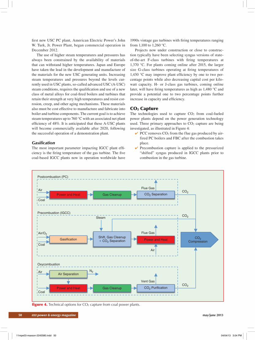
CO2 CaptureThe technologies used to capture CO2 from coal-fueled power plants depend on the power generation technology used. Three primary approaches to CO2 capture are being investigated, as illustrated in Figure 4:
✔ PCC removes CO2 from the flue gas produced by air-fired PC boilers and FBC after the combustion takes place.
✔ Precombustion capture is applied to the pressurized “shifted” syngas produced in IGCC plants prior to combustion in the gas turbine.
figure 4. Technical options for CO2 capture from coal power plants.
Power and Heat
Power and Heat
Power and Heat
Postcombustion (PC)
Precombustion (IGCC)
Oxycombustion
Coal
Air
Coal
Coal
Air
Air/O2
N2
Steam
Vent Gas
CO2
CO2
CO2
Air
Flue Gas
Flue Gas
Gas Cleanup
Gas Cleanup
CO2 Separation
CO2 Purification
Air Separation
Shift, Gas Cleanup+ CO2 Separation
CO2Compression
Gasification
11mpe03-maxson-2245580.indd 50 04/04/13 3:04 PM

may/june 2013 ieee power & energy magazine 51
✔ Oxycombustion fires the coal in a mixture of oxygen and recycled flue gas, producing a flue gas contain-ing primarily CO2 and water, allowing for relatively simple purification by cooling and condensing.
Post-Combustion CaptureAbsorption processes are the most mature PCC technolo-gies. A typical process passes flue gas through a packed-tower type absorber, where a chemical solvent selectively absorbs CO2. The CO2-laden rich solvent passes to a regenerating column (also called a stripper), where it is heated to release a nearly pure CO2 stream. The lean (in CO2) solvent is then returned to the absorber. The steam and auxiliary power requirements for solvent capture and CO2 compression may reduce net power plant output by 20–30% and reduce net plant efficiency by about 11 per-centage points. Amine-based solvents have been used for this purpose in chemical and natural gas plants. The use of an ammonia-based solvent has also recently demonstrated.
The primary objective of absorption PCC process devel-opment is substantial reductions in costs and energy use. Many of the approaches focus on the development of new solvents, particularly with greater absorption capacity, less energy required for regeneration, and greater ability to accommodate contaminants.
Southern Company is currently testing Mitsubishi Heavy Industries’ KM-CDR process at Alabama Power’s Plant Barry. A slipstream PCC system equivalent to about 25 MWe is capturing up to 550 tons CO2/day using KS-1, an advanced amine-based solvent. Over 100,000 tons of CO2 have been captured to date. Alstom’s chilled ammonia process under-went testing at a 20-MWe (~110,000 tons CO2/year) pilot plant at American Electric Power’s Mountaineer Station in West Virginia. The plant started CO2 capture in September 2009 and captured ~50,000 tons of CO2 during its operation, with 80–90% capture efficiency achievable and 99.9% CO2 purity.
While numerous larger-scale PCC demonstrations are in various stages of development, SaskPower’s Boundary Dam project in Canada is the only commercial-scale PCC actu-ally under construction anywhere in the world. The retrofit-ted PCC will capture 1 million tons/year of CO2 from one of Boundary Dam’s refurbished coal units, which has a net generating capacity of 110 MWe.
Novel PCC processes under development include: ✔ Adsorption: Novel designs of packed and fluidized beds are being investigated in parallel with solid
sorbent materials that can adsorb CO2, such as those based on carbon or metal organic frameworks.
✔ Membranes: Developers are working on polymer membranes that remove CO2 from flue gas with both high selectivity and permeability. While largely untested, membranes have potential to reduce the energy required to achieve separation.
Precombustion CapturePrecombustion capture in the IGCC power application has two major steps:
✔ converting the CO in the raw syngas to CO2 with the water-gas shift (WGS) reaction, producing a gas mix-ture consisting primarily of CO2 and hydrogen
✔ removing the CO2 from the mixture using AGR pro-cesses; the resulting hydrogen-rich syngas is supplied to the gas-turbine-based power block.
Precombustion capture has the advantage of captur-ing CO2 under pressure, which reduces CO2 compression requirements and incurs a lower energy penalty (~20–24%) than does current PCC technology. Research continues to further reduce this penalty.
The precombustion capture of CO2 employs mature chem-ical processes, and there are numerous proposed applica-tions for coal-fired IGCC plants with precombustion capture. However, the only project under construction is Mississippi Power’s Kemper County 524-MWe IGCC project.
The improvement plan for precombustion capture on IGCCs primarily focuses on syngas processing techniques that improve efficiency. Technologies include:
✔ Hydrogen transport membranes (HTM): Selec-tive membranes that separate hydrogen from the syn-gas, yielding a higher pressure CO2 product, have the potential to improve the efficiency of precombustion CO2 capture. A recent U.S. Department of Energy (DOE) evaluation showed that using HTM could increase efficiency by 2.9 percentage points.
✔ Warm-gas clean-up (WGCU): Precombustion cap-ture would be more efficient with separation systems that operate at temperatures closer to those of the WGS reaction (260–370 °C). WGCU removes con-taminants at high temperatures, eliminating the need for syngas cooling and expensive heat recovery sys-tems. Studies done by the U.S. DOE show a potential improvement in efficiency of one percentage point with WGCU.
The technologies used to capture CO2 from coal-fueled power plants depend on the power generation technology used.
11mpe03-maxson-2245580.indd 51 04/04/13 3:04 PM

52 ieee power & energy magazine may/june 2013
IGCC plants with high rates of CO2 capture require gas-turbine combustion systems that can burn high hydrogen-content syngas. Although there is extensive commercial experience with firing hydrogen-rich fuel gas in gas tur-bines, most of this experience is with older turbines that fire refinery fuel gas in which methane is the other main component.
The U.S. DOE is supporting two projects (one by GE and one by Siemens) to design large-scale, high-temperature tur-bines capable of firing hydrogen-rich fuels and achieving net plant efficiencies of 45–50%.
OxycombustionThe primary justification for considering oxycombustion is that it results in a flue gas rich in CO2 (70–90%, dry basis), reducing the costs of producing CO2 suitable for geologic storage. While oxycombustion power plants have a lower net efficiency (due to the high auxiliary power of the ASU), when compared to an air-fired plant with CO2 capture, they can be two to three percentage points higher in efficiency.
The first fully operational oxycombustion system is a 30-MWe demonstration at CS Energy’s Callide A Station in Australia that began commissioning in April 2011. In the United States, the DOE-funded FutureGen 2.0 project plans to repower Meredosia Unit 4 located in Illinois with a 168 MWe (gross) oxycombustion plant and to construct a CO2 pipeline and geological storage facility. The project plans to capture over 90% of the CO2 and sequester 1.1 mil-lion tons/year. The schedule calls for construction beginning in early 2014 and operations to begin in 2017.
The improvement plan for oxycombustion largely involves improving the CPU, which is the least mature system. For CPUs where a partial condensation process is included, the CO2 vented along with the noncondens-able gases can be captured, achieving an overall CO2 cap-ture greater than 98%. Technologies under development to accomplish this include:
✔ pressure-swing absorption processes used to capture CO2 from the vent gas and recycle it back to the inlet of the CPU
✔ polymeric membranes selective for CO2/oxygen that might separate and recycle the majority of these gases back to the boiler. These membranes might also reduce the size and power demand of the ASU by 5%.
CO2 Compression, Transport, and StorageAlthough as much as 80% of the cost of CCS is attributable to the capture process, most of the uncertainties surround the means of permanently storing CO2. The industry and public need confidence in the ability to safely inject and store CO2 in underground formations over very long periods with no undesirable side effects.
CompressionCO2 transport via pipelines is commercially mature. However, energy requirements for CO2 compression are substantial. Most commercial storage applications pres-surize CO2 to inject as a SC fluid. Compressors required to raise CO2 pressure to such a state consume significant power requiring as much as 8% of the host power plant’s net power output.
Southwest Research Institute is investigating two novel compression systems with the potential to reduce CO2 com-pression power by 35%. One concept is a semi-isothermal compression process, where the CO2 is continually cooled using an internal cooling jacket, rather than using conven-tional interstage cooling; the other concept involves the use of refrigeration to liquefy the CO2, so that its pressure can be increased using a cryogenic pump rather than a compressor.
TransportationThe storage of CO2 from some power plants may require trans-portation over long distances to suitable injection locations. Although CO2 may be transported by truck, train, or barge, pipelines are likely to be the only economical mode of trans-portation for the large quantities of CO2 resulting from CCS.
The technical, economic, and permitting aspects of CO2 pipeline transport are generally well understood. However, the pipeline transport of CO2 may require a minimum purity specification to prevent pipeline corrosion and reduce haz-ards in the event of an accidental release. This will have an impact on the cost of CO2 capture as higher purity standards require more CO2 purification.
StorageThe storage of captured CO2 in underground or undersea locations remains a significant issue for implementing a large-scale CCS program worldwide. Options for geologic storage include depleted gas-bearing formations, saline for-mations, and deep, unminable coal seams as well as storage in oil-bearing formations and as a side benefit to enhanced oil recovery, which is widespread in some regions.
Four large-scale geologic projects have been in place for some time and have successfully stored significant amounts of CO2. The Weyburn-Midale project in Saskatch-ewan, Canada, began in 2008 and stores ~2.4 million tons CO2/year. The Sleipner saline aquifer CO2 storage project in the North Sea began injecting CO2 from natural gas purifica-tion in 1996 at an injection rate of ~1 million tons CO2/year. The Snøhvit project began injection in the Barents Sea in 2008, with a capacity of ~0.7 million tons CO2/year. The In Salah project in Algeria began injection in 2004 and stores ~1.2 million tons CO2/year.
In the United States, the seven regional partnerships of DOE’s Regional Carbon Sequestration Partnerships pro-gram are conducting pilot-scale CO2 injection validation tests in differing geologic formations. These pilot-scale tests are to be followed by larger volume tests, involving storage
11mpe03-maxson-2245580.indd 52 04/04/13 3:04 PM

may/june 2013 ieee power & energy magazine 53
of ~1 million tons of CO2 or more, along with post-injection monitoring. In the ongoing Southern PCC demonstration at Plant Barry, the captured CO2 is being transported by pipeline ~16 km and injected into a saline formation. Over 40,000 tons have been stored to date.
Site characterization and monitoring are critical to suc-cessful storage operations. While storage opportunities are present in many areas in the world, some regions do not have suitable storages sites, which may require developing pipe-line transportation networks.
Unresolved barriers include regulatory, legal, and long-term liability issues associated with storage; addressing these will be critical to timely commercialization. Additional storage dem-onstrations are likely to be required to gain public acceptance.
Near-Zero EmissionsA critical element in research for future coal generation is the approach to NZE coal-fired power plants. A number of factors drive the need for NZE R&D. In the short term, coal plants will need to meet increasingly restrictive emission regulations for NOX, sulfur dioxide (SO2), sulfur trioxide (SO3), mercury, selenium, PM, and a number of organics. In the longer term, the need for NZE technologies for air-fired plants is linked to PCC processes as several CO2 capture technologies require inlet flue gas with extremely low levels of SO2 and NOX.
Current environmental controls are able to reduce emissions of NOX, SO2, SO3, and mercury to very low levels but usually not to NZE levels on all coals consistently throughout the year. Technology advances, enhanced instrumentation, and a final polishing step may be required to attain NZEs.
Perhaps the greatest promise of oxycombustion is the pros-pect of a true NZE. This would be accomplished by injecting the entire flue gas flow into geological storage resulting in no flue gas emissions at all, accepting that some underground volume will be occupied by gases other than CO2.
MercuryThe leading technology for removing mercury from coal-derived flue gas or syngas is ACI, which utilizes extremely porous carbon particles capable of adsorbing mercury. ACI has been applied to existing PC power plants to reduce mer-cury emissions by up to 90%. A number of researchers are investigating technologies by which the suitable carbon-based mercury sorbents might be manufactured on site using coal as the raw material. Mercury control cost reductions of 50% might be achieved by these technologies.
In IGCC units, ACI can remove 95% or more of the mercury in syngas prior to combustion.
NOX EmissionsFor PC plants, state-of-the-art NOX controls in boilers com-bine low-NOX firing techniques that limit NOX formation with chemical reduction technology that destroys NOX after it has formed. In a boiler, staged combustion can reduce
NOX formation by 35–55%. SCR technology can reduce flue gas NOX to 85–90% below SCR inlet levels. These technol-ogy combinations yield a net overall reduction in NOX of 90–95%.
FBC boilers operate at lower temperatures, which inhibit the formation of NOX and typically use selective noncata-lytic reduction systems (which also use an ammonia-based reagent but are located in regions where the higher tempera-ture window causes the reduction reactions to proceed with-out the need for catalysts). Consistently achieving ultra-low NOX emissions in PC and FBC systems will depend on tech-nology advancements for combustion flame control (NOX production) and improvements in NOX reduction catalysts and associated regent distribution control.
During gasification in an IGCC plant, fuel-bound nitrogen is converted primarily to molecular nitrogen or ammonia. The ammonia is removed by water washing. Consequently the only NOX production mechanism in an IGCC plant is “thermal NOX” formed in high-flame temperature zones of the gas turbine. State-of-the-art NOX controls in IGCC gas turbines combine low-NOX firing techniques to limit thermal NOX formation with chemical reduction to destroy NOX after it has formed. In syngas-fired gas turbines, low-NOX com-bustors typically reduce NOX production by 70–90%. SCR systems can reduce flue gas NOX concentrations to 85–90% (or more) below SCR inlet levels. These technology com-binations yield a net overall reduction in gas-turbine NOX emissions of 95–99%.
PM EmissionsOptions for PM control are a fabric filter (bag house) or an ESP, which uses high-voltage electrodes to impart a negative charge to the particles entrained in the flue gas. The parti-cles are then collected by and removed from a grounded sur-face. These technologies can reduce PM emissions to under 15 mg/Nm3, a reduction of more than 99%.
Wet ESPs are increasingly being used as a “polishing” control device to further reduce levels of fine particulate and condensable particulate (primarily sulfuric acid mist) downstream of a wet FGD absorber. These could potentially reduce PM to near zero levels.
PM in syngas can be removed by dry processes such as a pulse-cleaned, rigid barrier filter or by wet processes using venturi scrubbers (referred to as gas scrubbing). Both methods achieve over 99% particulate removal. Particulate formation in the gas turbine and HRSG are minimized by sulfur removal and by combustor designs that achieve thor-ough fuel burnout.
Sulfur EmissionsSOX emissions from coal-fired PC boilers are controlled by wet or dry FGDs or scrubbers. These systems inject alka-line reagents (typically finely ground limestone, lime, or soda ash) into flue gas to react with SO2, reducing emissions by 95–98%. A substantial portion of SO3 and sulfuric acid in the
11mpe03-maxson-2245580.indd 53 04/04/13 3:04 PM

54 ieee power & energy magazine may/june 2013
flue gas is also removed by the FGD. The reduction of SOX emissions in PC and FBC systems to near-zero levels will require a better design and operation management of FGDs to provide macrocontrol of gas-sorbent contact and micro-conditions at the sorbent surface that facilitate sulfur capture.
During gasification, coal-bound sulfur is converted pri-marily to hydrogen sulfide (H2S) and a small amount of carbonyl sulfide (COS). Regenerable solvents are used to remove H2S and other acid gases from the syngas prior to combustion. Such processes are very effective, often remov-ing 99.5% or more of the H2S. A hydrolysis catalyst converts most of the COS to H2S upstream of the AGR process.
Multipollutant Control Emissions SystemsThe footprint of the individual AQCS components typically included in a new coal-fired power plant is often greater than the boiler and turbine block footprint. There are active development efforts underway to reduce the cost of environ-mental controls by employing technologies that can control more than one of the emissions at once.
For emissions with newly proposed regulations (e.g., sele-nium and organics), R&D initially will focus more on the underlying mechanisms, as well as independent assessments of emerging controls.
Future TechnologiesMore advanced future technologies aiming at significant improvements in coal power plant performance, several of which represent different platforms for coal power gen-eration, are in earlier stages of development and might be available commercially in the 2025–2030 timeframe.
Advanced Fuel CellsFuel cells, which have been the focus of a decades-long development process, con-tinue to hold the promise of providing a step change in efficiency for coal-based power plants. The basic electrochemi-cal cells operate near 1-V dc, depending on the electrochemistry employed and other operating conditions. Cell current flow is generally proportional to fuel use. The individual cells must be stacked to produce useful voltages for inversion to utility-grade power. The cell electrochem-istries under consideration for coal-fueled fuel cell power are generally high tem-perature leading to major mechanical and material challenges in designing the fuel cell stacks and the electrical connections.
Solid oxide fuel cells are leading candi-dates for high-efficiency integrated gasifi-cation fuel cell (IGFC) power plants. Such plants are similar to gas-turbine combined cycle plants with the fuel cell replacing the gas turbine combustor as shown in
Figure 5. The U.S. DOE has estimated that an IGFC with CO2 capture could achieve a net thermal efficiency of 56.3%. The U.S. DOE goal is to have a 5-MWe system operating by 2015.
The durability of the electrochemical components is the primary technical challenge. In addition, development of economical, durable, and maintainable designs for air and syngas supply to individual cells (without leakage/bypass) and electrical connections that are durable at the high tem-peratures remain challenges.
Chemical LoopingChemical looping combustion (CLC) is a technology that uses a reversible chemical reaction to separate oxygen from air. Suitable solids are oxidized in an air reactor and then transferred to a fuel reactor where the solid-oxygen reaction is reversed and the fuel burned. The process is shown schemati-cally in Figure 6. Selected metal oxides are candidate carriers as is a chemical system using calcium sulfide/calcium sulfate.
A successful CLC process would dramatically reduce auxiliary power use in air separation by replacing the air compressors in a cryogenic ASU with fluidizing blowers in the CLC process. The use of A-USC steam conditions in a CLC power plant with CO2 capture could achieve net effi-ciencies near 41%.
The largest coal-based CLC process development unit deployed to date is Alstom’s 3-MWth prototype in Wind-sor, Connecticut, in operation since early 2011. It is being used to develop solids handling schemes and to characterize overall process performance of the calcium sulfide/sulfate system. Pilot-scale facilities might be deployed in the 2015 time frame.
figure 5. Solid oxide IGFC power plant schematic.
Flue Gas
Inverter-
+
Syngas - CH4 - CO - H2 - CO2 - H2O
SOFC Cathode
SOFC Anode
Combustor
Air
Compressor Turbine
~
Generator
Cathode Reaction: O2 + 4 e- 2 O2-
Anode Reactions: CH4 + H2O 3 H2 + CO
CO + H2O H2 + CO2
H2 + O2- H2O + 2e-
CO + O2- 2 CO2 + e-
~
11mpe03-maxson-2245580.indd 54 04/04/13 3:04 PM

may/june 2013 ieee power & energy magazine 55
Closed Brayton Power CyclesThe Rankine power cycle is the backbone of the electric-ity industry in most of the world. Over the last ten years, a number of organizations have conducted analytical and process development work to advance closed Brayton power cycles using SC CO2 as the working fluid in lieu of the Ran-kine cycle. The prospect of higher efficiency is the primary motivation for considering this power cycle for coal-fueled applications. Variations of the SC CO2 closed Brayton cycle have been proposed for generating electricity from nuclear, fossil fuels, solar thermal, geothermal, heat sources, and as an alternative to the Rankine bottoming cycle commonly deployed in natural gas combined cycle plants. The technol-ogy might also be suitable for repowering as a topping cycle added to existing subcritical Rankine cycles to increase plant output and efficiency.
A simplified version of a closed Brayton power cycle is shown in Figure 7. The working fluid does not change phase; it is compressed, heated, and expanded through a turbine. In a closed Brayton cycle, the working fluid exiting the turbine is cooled and sent to the compressor, and heating the working fluid is done by indirect heat exchange rather than by direct combustion. SC CO2 (pressure greater than 73.9 bar) is available at modest cost, does not change phase, and has high density/low compressibility, which minimizes compression power, making it an attractive candidate for the closed Brayton cycle.
This cycle offers the prospect of a higher efficiency of two to four percentage points (at comparable turbine inlet pressures and temperatures), an associated reduction in CO2 emissions, and lower turbo-machinery costs as compared to the incumbent Rankine power cycle.
Complete cycles have been constructed at lab scales of ~200 kW. Multiple pilot deployments in the range 7–25 MWe level are anticipated in 2013–2014.
ConclusionsThere are numerous technical options available and under development to improve coal power plant efficiency, reduce conventional emissions to near-zero levels, and capture CO2 for geological storage. However, many of the technologies are not yet at the level of developmental maturity required for affordable widespread deployment, and time is needed to test and validate new technologies. Achieving these goals will require an acknowledgment of the urgency of the chal-lenges and a sustained commitment to a broad program of aggressive public- and private-sector R&D.
For Further ReadingIntergovernmental Panel on Climate Change, Carbon Dioxide Capture and Storage. Cambridge, U.K.: Cambridge Univ. Press, 2005.
B. Miller, Clean Coal Engineering Technology. Burling-ton, VT: Elsevier, 2011.
“CO2 capture technologies: Report sponsored by the GCCSI,” EPRI, Palo Alto, CA, 2011.
D. Gray, J. Plunkett, S. Salerno, C. White, and G. Tomlin-son, “Current and future technologies for gasification-based power generation,” National Energy Technology Laboratory, U.S. Department of Energy, Pub. No. DOE/NETL-2009/1389, revision 1, 2010.
M. Shah, N. Degenstein, M. Zanfir, R. Solunke, R. Kumar, J. Bugayong, and K. Burgers, “Purification of oxy-combustion flue gas for SOX/NOX removal and high CO2 recovery,” in Proc. 2nd IEAGHG Oxyfuel Combustion Conf., Yeppoon, Queensland, Australia, 2011.
Babcock and Wilcox Co., Steam: Its Generation and Use, 41st ed. Whitefish, MT: Kessinger, 2005.
D. Zhang, ed., Ultra-Supercritical Coal Power Plant. Cambridge, U.K.: Woodhead Publishing, 2013.
BiographiesAndrew Maxson is with the Electric Power Research Insti-tute, Palo Alto, California.
David Thimsen is with the Electric Power Research Institute, Palo Alto, California.
p&e
figure 7. Simplified closed Brayton cycle.
Compressor Turbine
Cooler
Fired Heater
Recuperator
figure 6. Simplified schematic for chemical looping using a metal oxide carrier.
Steam
Me MeO
CO2 + H2O
N2 + O2Ox
Red
Air
Fuel
Air Reactor (Oxidizer)
Fuel Reactor (Reducer)
11mpe03-maxson-2245580.indd 55 04/04/13 3:04 PM