the garrattmaker project - metre-gauge beyer … · nally introduced by beyer, peacock & co....
TRANSCRIPT

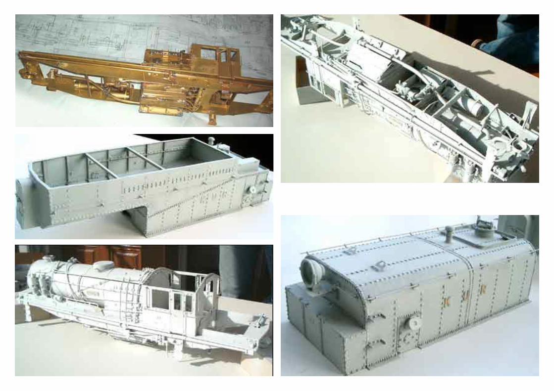
1:22,5 G-scale, (45mm track),„reconstruction“ of the Metre-Gauge Beyer-Garratt 4-8-4 + 4-8-4 for the Kenya & Uganda Railways 200 detail-picts and 260 Beyer-Pea-cock drawings made it possible to reconstruct the 4-8-4 + 4-8-4 Metre-Gauge Beyer-Garratt 1:22,5 G-sca-le.
THE GARRATTMAKER PROJECTMENGO:Beyer Peacock 6905 / 1939KUR Class / Nr. EC3 / 77
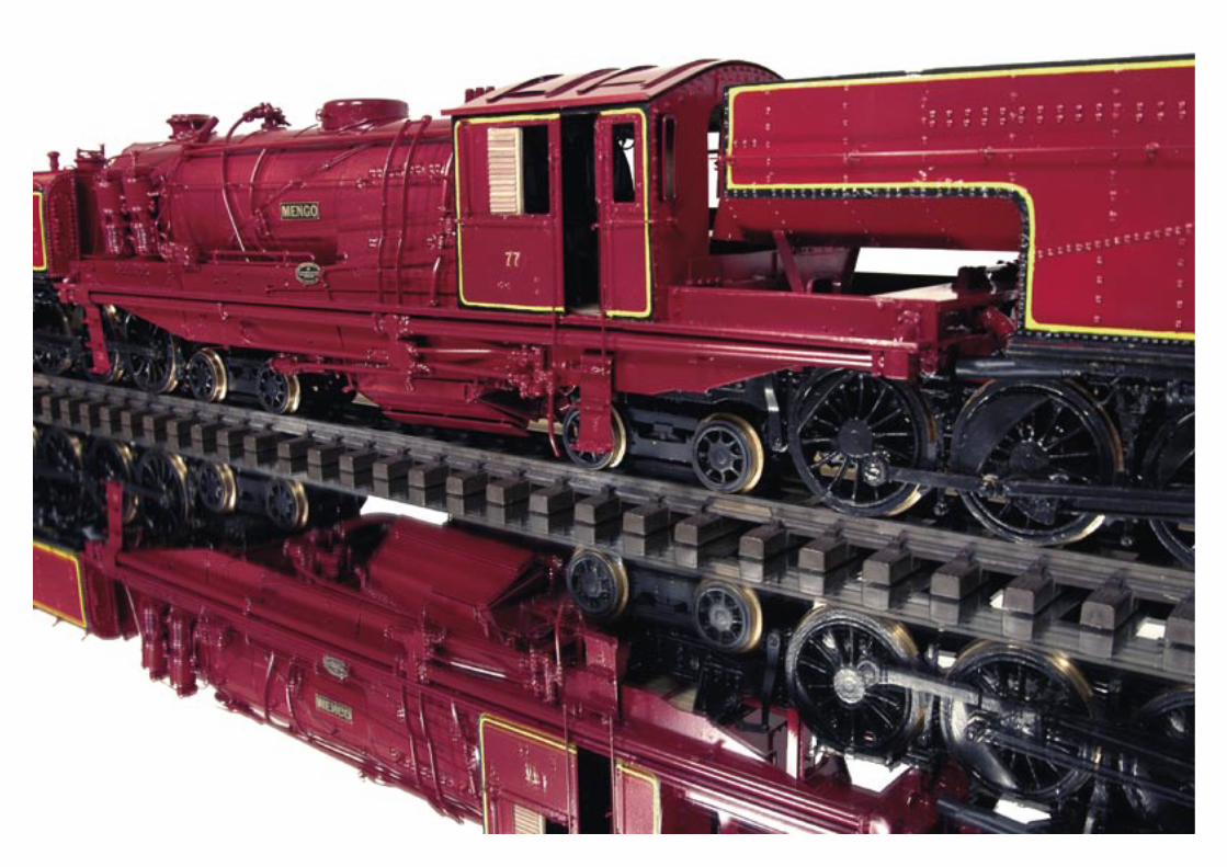
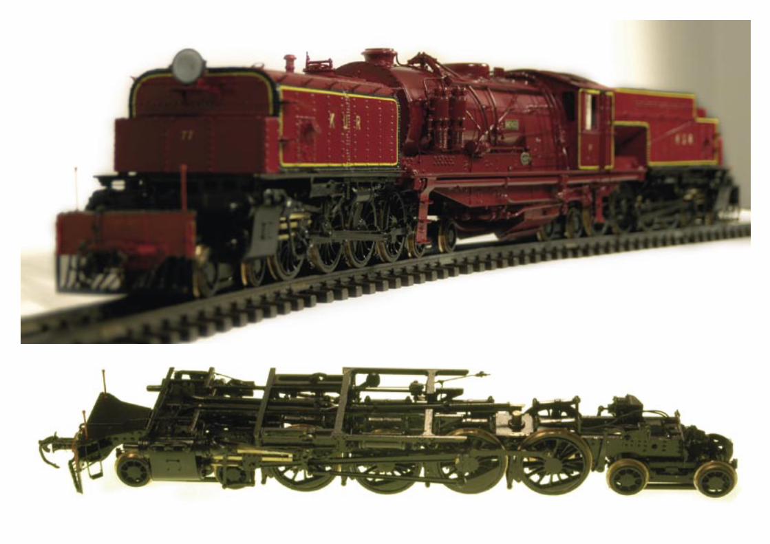
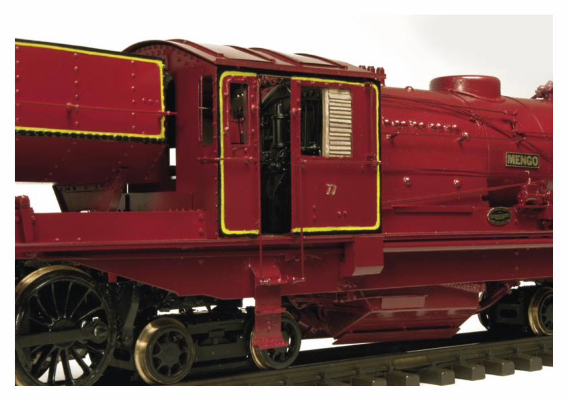
MENGO is the first KUR-Garratt of a series of 12 handmade 1:22,5 brass models. An important value was the mainte-nance of constructional guidelines fitting to the original MENGO. The model loco is primarily a showpi-ece.It is proposed by a electric motor and therefore limited suitable for regular usage. The electric current transmission passes by the rail over 8 axles is as invisible as it‘s elec-tric motor (through the oilpipe of the boogie-axleboxes)The minimum radius is 6 meters/20 feet. The colour varnish corresponds to the authentic KUR Original varnish. The pure construction time of the MENGO was 12 months. Numbers and nameplate corres-pond to the original.
Photocopyrightby Bernhard Schramm (all Mengo)and Michael Schachinger (Karamoja)www.garrattmaker.com
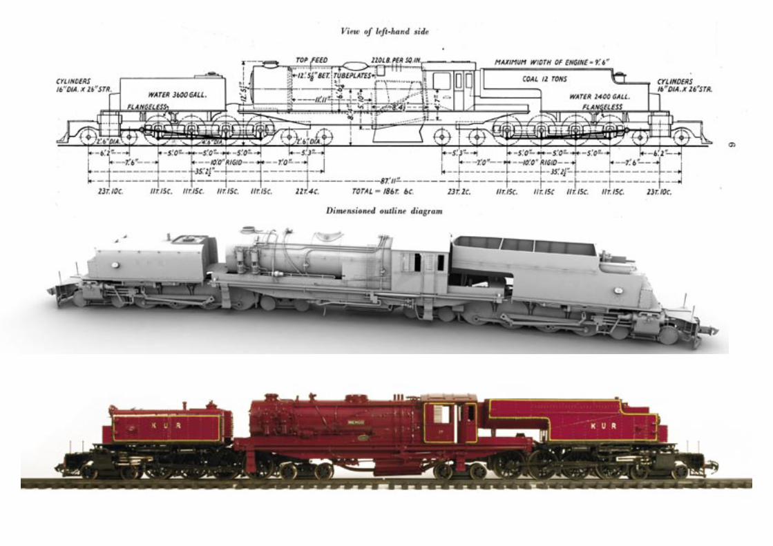

Just one of these twelve successful Garratt gigants has survived until today.„KARAMOJA“BP 6974/1940 Nr 87 of the Kenya Uganda Railway
KARAMOJA was modified at some details approximate 1960
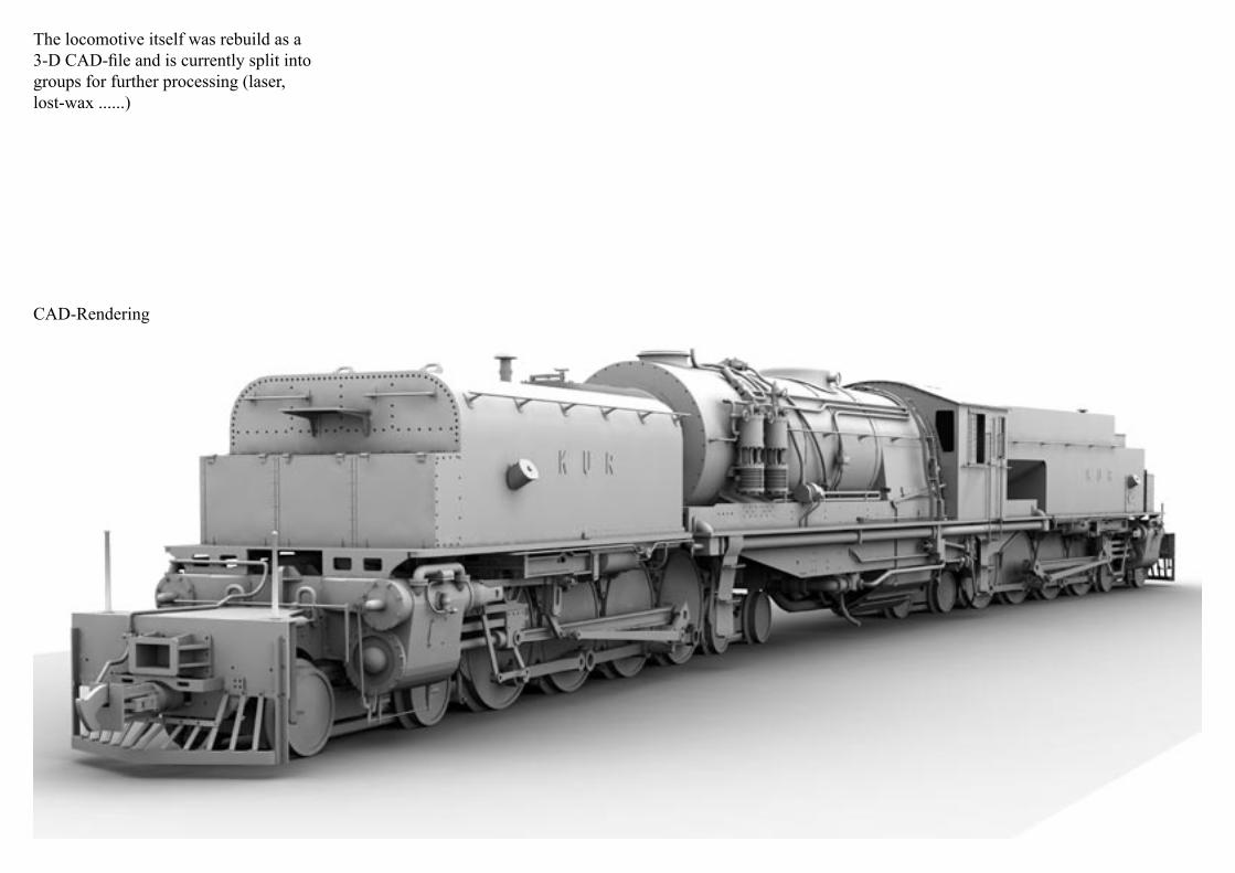
The locomotive itself was rebuild as a 3-D CAD-file and is currently split into groups for further processing (laser, lost-wax ......)
CAD-Rendering


CAD-Rendering boogieparts
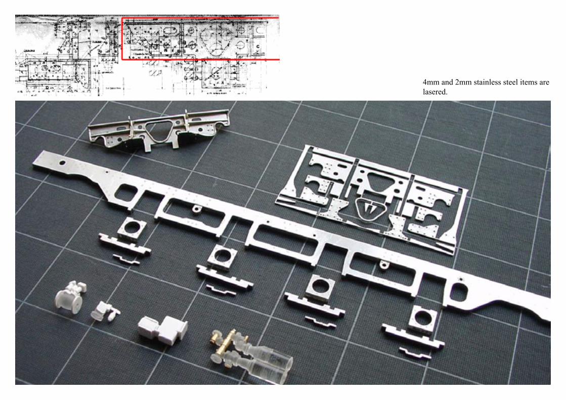
4mm and 2mm stainless steel items are lasered.

The pieces are photo-etched brass parts. They are done and ready for assembling.
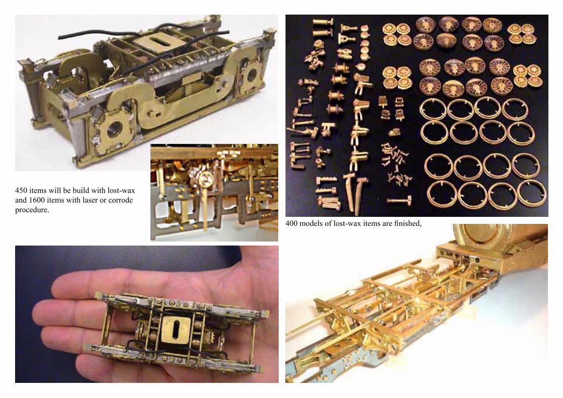
400 models of lost-wax items are finished,
450 items will be build with lost-wax and 1600 items with laser or corrode procedure.


Used with the permission of the editor of Rail-way Gazette International www.railwaygazette.com
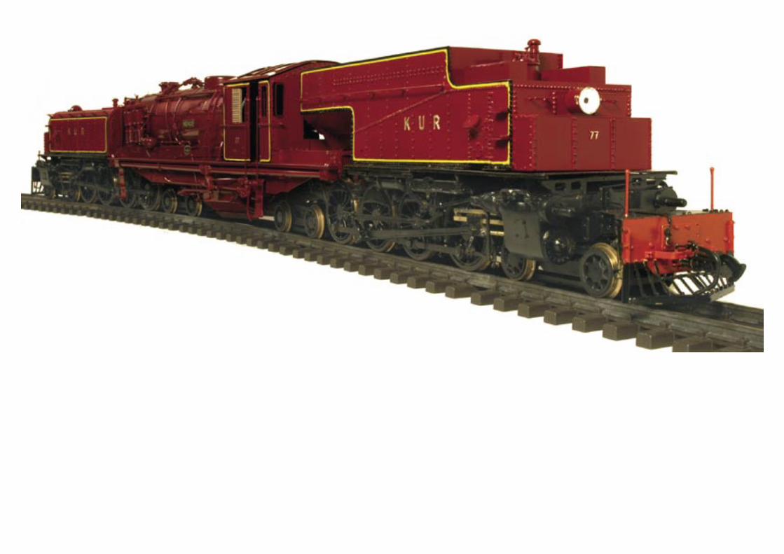
4-8-4 t+ 4-8-4Metre-Gauge Beyer-GarrattLocomotives for the Kenya & Uganda RailwaysThese engine are the first in the world to have this wheel arrangement and the largest 50-lb. rail locomotives ever built
Reprinted from THE RAILWAY GA-ZETTE, July 21, 1939 BEYER, PEA-COCK & CO. LTD., LOCOMOTIVE ENGINEERS, MANCHESTER
Editorial Note from „The Railway Ga-zette“ July 21, 1939The First 4-8-4 + 4-8-4 LocomotiveThe first Beyer-Garratt locomotive to be fitted with an inside four-wheel bogie, a 4-6-4 + 4-6-4, was described in our issue of February 26, 1937. Another example of the inclusion of the four-wheel bogie on the inside of the engine units of a Garratt engine is the subject of an article this week. The wheel arrangement in this case is 4-8-4 + 4-8-4, and, incidentally, this is the first time such a wheel arrange-ment has been embodied in any steam locomotive. The engines, of which six have been built and another six are under construction, are for the Kenya & Uganda Railways. The huge boiler and extended wheel arrangement that this system of articulation permits is noteworthy, and the fact that the en-gine is to operate on a 50-lb. rail, has a maximum axleload of less than 12 tons, and can negotiate a 275-ft. radius curve, yet weighs 186 tons, makes this locomotive a conspicuous example, of the designing capacity and in genuity of the British locomotive manufacturer. The Kenya & Uganda Railways have used Garratt engines for many years, and before long the 879 miles of main line will be operated almost entirely
by this type of engine, which is an indication of the state of reliability and availability it has attained, and how it can give to a railway restricted by a narrow gauge and light rail the carrying capacity of a standard-gauge railway.
NEW 4-8-4 + 4-8-4 METRE-GAUGE BEYER-GARRATT LOCOMOTIVES, KENYA & UGANDA RAILWAYSThese engines are the first i n the world to have this wheel arrangement and the largest 50-lb. rail locomotives ever builtOne of the exclusive characteristics of the Garratt principle of articulation is the ability to accommodate on each en-gine unit any wheel diameter or wheel arrangement which can be applied in the ordinary type of engine, and the new design of Beyer-Garratt locomoti-ve we now describe and illustrate is an excellent example of the way in which so extended a wheel arrangement as 4-8-4 + 4-8-4 can be incorporated. The order, comprising six locomotives of this type, has recently been com-pleted by Beyer, Peacock & Co. Ltd. at Gorton, Manchester, and shipped, and some are already in service. An order for a further six has already been placed. This new type has been desig-ned by Beyer, Peacock & Co. Ltd. to the detailed specification of the Chief Mechanical Engineer, Mr. K. C. Stra-han (now retired), and the subsequent requirements of Mr. H. B. Stoyle, present Chief Mechanical Engineer and

previously Locomotive Running Su-perintendent of the railway. The Kenya & Uganda Railways administration has been a user of Garratt locomotives for several years, the 36 engines of this type operating about two-thirds of the total main-line traffic. Perhaps nowhere in the world have Garratt engines been worked more intensively, the mileages obtained being a record for a narrow-gauge line of this kind. The new design not only embodies the makers‘ impro-vements culled from the experience of Garratts in service in various parts of the world, but includes various modifi-cations and alterations suggested by the railway, based on its long experience, which combine to make these new en-gines particularly interesting and out-standing examples of the present-day Garratt. They have been built under the supervision and inspection of the Crown Agents for the Colonies. Before passing on to a detailed description of these engines, it is therefore interesting to observe the extraordinary size of the locomotive, a point with which we were particularly struck when we in-spected one of the type, considering the restrictive conditions of a metre-gauge and 50-lb. rail. On this light rail-half the weight of the rail in Great Britain-and on a gauge 1 ft. 5 1/8 in. less with more difficult grade and curvature con-ditions, the tractive effort of the engine is equal to the biggest passenger engi-nes in Great Britain while the boiler is practically equal in horsepower, having
a similar size grate and an even larger barrel diameter despite the total height to chimney top from rail level of 12 ft. 5 1/2 in., which is nearly a foot lower than the highest British dimension. The locomotive further weighs roughly 20 tons more than the largest British types, the width over the running board is 9 ft. 6 in., and the footplate area is considerably larger than that of many standard gauge engines. The design embodies many interesting features, some of which constitute a fundamen-tal departure from the practice origi-nally introduced by Beyer, Peacock & Co. Ltd. The two principal differences, apart from the wheel arrangement, are the inversion of the pivot centres, the male portion being on the engine unit instead of on the boiler cradle, and the alteration of the valve gear to bring the quadrant block of the links of each engine unit to the same position for whichever direction the engine is running.
This is the first time that the 4-8-4 + 4-8-4 wheel arrangement has been ad-opted; it is designed for 573-ft. radius curves on the main line and 275-ft cur-ves in sidings. It has naturally brought fresh problems for solution such as the distribution of weight in relation to the strength of frames, alteration of the relative position of the pivot centres, clearances necessary for the longer units and method of compensation, &c., while the inside dimension bet-
ween the unit bar frames of only 2 ft. in this case is an ever present difficulty to the designer of narrow-gauge engines. Further, it was specified that the engi-nes were to be designed to facilitate conversion to 3 ft. 6 in. gauge with the minimum of alteration; thus the cylinders and rods and motion ape centred for the wider gauge, a wider wheel centre providing for the shifting of the tyres outwards. The engine has also been designed to take care of the possible conversion of the Westinghouse brake to vacuum, when the gauge is altered, and also for the ultimate introduction of automatic couplers. Despite these features, however, a far greater measu-re of accessibility has been obtained throughout the locomotive than hither-to. Previous Beyer-Garratt locomotives on the Kenya & Uganda Railways have been of the 4-8-2 + 2-8-4 wheel arran-gement, with a coupled wheel diameter of 3 ft. 7 in. in keeping with an existing wheel on a standard ordinary engine. With the gradual speeding up of traffic and the extended use of Garratt engi-nes over the whole main line, where the grades are easier, it was decided to increase the size of wheel in the pre-sent engines to 4 ft. 6 in., thus reducing the revolutions per mile by 20 per cent. with a consequently better balanced and freer running engine, resulting in considerably reduced maintenance. The introduction of the inside four-wheeled bogies has permitted a larger boiler for
continued maximum output and also enabled larger coal and water supplies to be carried. The tracking properties of the engine have also been considerably improved by the guiding and protective effect of the bogies fore and aft, of the coupled system, which should result in reduced wear of rails and flanges. Existing Garratt engines, which work passenger and goods trains, are opera-ted mainly by two sets of engine men, either Europeans or Asians, and Afri-can firemen, one set resting in a „ caboose „ and changing over every 8 hours. This system has been in vogue for some years and round trips of 660 miles-Nairobi-Mombassa- Nairobi are run daily. With the new engines it is contemplated to run from Nairobi to Kampala and back, a round trip of 1,100 miles, and to this end various features have been introduced to lessen the enginemen‘s responsibility and work on the road, such as roller bearings on all bogie wheels and an extensive use of grease lubrication as detailed later.General DesignFrom the various illustrations a good idea can be obtained of the general layout of the locomotive. The boiler rests in the usual plate type of cradle frame, lengthened to take care of the new wheel arrangement; the plates are stayed together at each end by a steel casting of massive proportions, carrying the top portion of the pivot centre arrangement. Adjacent castings
form a saddle to which the boiler is stayed, the firebox being supported by expansion brackets riveted to the wrapper sheet, and resting on the top of the cradle frame. The cradle frame is also suitably stayed along its length. The engine unit frames are of the bar type 4 in. thick, 35 ft. long, and are made from rolled steel slabs of Ap-pleby-Frodingham Steel Company‘s manufacture. These are bound together by various steel castings, the principal ones including the drag box at the front end and a large casting incorporating the male portion of the pivot. Further, the cylinders, made in two castings, are bolted together on the centre line, giving additional rigidity to the whole chassis. The inside extremities of the bar frames have also substantial steel castings to carry the 20 odd tons with which the bogies are loaded. The pivot arrangement as already mentioned, has been turned upside down compared with previous practice, access of coal or smokebox ash and dirt generally being thus prevented. The centres are provided with re- newable seatings and a brass liner, while the bottom centre is fitted with a renewable ring. The design embodies the Beyer, Peacock patent adjustable arrangement for taking up wear; the adjustment, which can be made from the outside of the engine, is by means of a wedge acting on a seg-ment. The side bearers are the maker‘s latest type consisting of grease-lubrica-ted rollers.
The following are the principal dimen-sions :Cylinders (4), dia. . . . . . . . . 16 in. stroke. . . . . . . . .......... 26 in.Piston valves, dia. . . . . . . . . 9 in. max. travel. . . . . . . . . 5 in.Coupled wheels, dia. . . . . 4 ft. 6 in.Evaporative heating surface, tubes. . 2,015 sq. ft.firebox. . 251 sq. ft . (including two syphons and two arch tubes) Total . . . . . . . . . . . . . . 2,266 sq. ft.Superheater (inside) . . . . 484 sq. ft.Combined total . . . . .. . 2,750 sq. ft.Grate area . . .. . . . . . . . . 48.5 sq. ft.Boiler pressure . .. . . . 220 lb./sq. in.Coal capacity . . . . . . . . . .. . 12 tonsWater capacity . . .. . . . . . 6,000 gal.Tractive effort (at 75 per cent.b.p.) 40,670 lb. (at 78 per cent. b.p.). . . . . 46,090 lb.Weight of locomotive in working order 186 tonsBoilerAs will be seen, the boiler is of quite exceptional size for the metre gauge, the outside diameter of the barrel being as large as 6 ft. 9 1/2 in. and the grate area 48.5 sq. ft. The pressure is 220 lb. per sq. in. The boiler barrel is made up of two sheets of Park Gate Iron & Steel Company‘s manufacture; the smoke-box tubeplate is of the drumhead type. The boiler is fitted with a scum cock and blow-down cock operated from the side of the engine, and a main stop val-ve to the dry pipe is fitted in the dome.
The firebox, it will be noted, is of, the round-top type as against the Belpaire on previous Garratt engines supplied to this railway, while the inner firebox is of steel as against copper on previous engines. This inner firebox, which is fitted with two Nicholson thermic syphons and two arch tubes, is made of Colville‘s special Double Crown firebox steel and is completely welded throughout. The roof stays are of the radial type with three rows of flexible stays at the front end. Flexible stays are also provided in the breaking areas on the sides are also on the two top rows. The smokebox is of large capacity and fitted with a hot water ash ejector. Jum-per top blastpipes have been fitted for experimental purposes but plain caps have also been supplied. The superhe-ater is of the Superheater Company‘s manufacture, fitted with the multiple valve regulator positioned between the superheater and the cylinders, the superheater elements, header, and inter-nal steam pipe thus being continually under full boiler pressure while also affording instant and fine regulation of the steam supply to the cylinders. The-re are 38 flue tubes, 5 1/4 in. outside diameter, with superheater elements l 3/8 in. outside diameter, 10 w.g. thick, having Melesco forged return bends and ball joint attachment to the header. The number of small tubes is 220 of 1 7/8 in. outside dia- meter; all the tubes are of Howell‘s Aquacidox steel, The barrel is clothed, as are also firebox and
cylinders with J. W. Roberts‘s Limpet asbestos mattresses. The boiler is fed by a No. 12 Gresham & Craven live steam injector placed beneath the cab, and also by a Davies & Metcalfe ex-haust steam injector No, 11, both deli-vering into the barel by double top-feed clackboxes. The exhaust steam injector has a capacity of 3,000 gal. per hr. and is controlled by a lever in the cab with a graduated scale by the regulation of which the fireman can maintain a constant feed to the boiler to ensu-re the maximum quantity of exhaust steam being utilised. The safety valves consist of three 24-in. dia. of the Ross muffled pop type. The firegrate arran-gement consists of rocking firebars in two sections, each having a drop grate at the front, the firebars being operated by steam and hand. The control levers are marked for the up and level posi-tions, the cylinder for each section of firebars being placed on each side of the boiler cradle frame. These can be seen in the illustrations. The ashpan is similar to the latest selfcleaning type fitted to South African Beyer-Garratt engines, discharging between the rails. It is fitted with a front and back damper and side doors and slides, all operated from the cab.Cylinders and Valve GearThe cylinders, of cast iron, have cast-iron pistons fitted with two narrow rings. The piston valves, of the trunk type, are 9 in. in diameter and fitted with four narrow rings. The valves, ac-
tuated by Walschaerts gear, have a tra-vel of 5 in. The links are of the built-up box type with the reversing shaft fixed behind the link. Reference has already been made to the alteration in this de-sign from the usual practice of combi-ning the valve gears of the two engines. Previously one engine was always in back gear, continuous running thus being done with the quadrant block in the top section of the link. This, howe-ver, had the advantage of placing the valve gears in balance as regards their control, and a reversal of motion has thus had to be introduced to bring both engines into the same gear position. This has necessitated the introduction of a balance-weight which can be clearly seen in the close-up view of the front engine unit. The valve gear is controlled by steam reversing gear with an oil cataract locking cylinder similar to those already fitted to hundreds of Garratt engines. The crosshead, of cast steel, is of the Laird type. Lubrication to the slidebars is by a three-feed oil box going to the top and bottom bars; the lubrication being, so to speak, internal, the ingress of dust and foreign matter is prevented by the fitting of oil pads at the end of the slipper and on the crosshead to protect the sides of the bottom bar. The slippers are of cast iron with white-metal lining. Britimp metallic packing is arranged for the piston rods. Attention may be drawn to the layout of the valve gear generally, such as the length of the eccentric rod,
which is fitted with S.K.F. spherical roller bearings. The connecting rod is also of considerable length, being 12 ft. 6 in. long. The big end is fitted with a floating bush for grease lubrication referred to later under this heading. Coasting is provided for by the fitting of by-pass valves and air relief valves except in the case of the sixth engine, where the by-pass valves arc blanked off and replaced by a new automatic drifting appliance manufactured by J. Stone & Co. Ltd., which has already been in experimental use in Kenya with very satisfactory results (see illust-ration). This equipment consists of a double-acting vacuum pump driven off the locomotive motion, controlling a steam shut-down and steam pressure reducing valve for regulating the sup-ply of drifting steam to the cylinders. The purpose of this device is to render unnecessary the use of by-pass and air drifting valves by maintaining a cont-rolled supply of low pressure steam to the locomotive cylinders when the lo-comotive is in motion and the regulator is closed. When the locomotive stops the vacuum pump ceases to function, so shutting off the supply of steam, any steam already in the steam chests (or leakage of steam) being exhausted to the atmosphere. The main feature is, therefore, to provide an automatic by-pass for the locomotive regulator controlled by the movement of the locomotive and the pressure existing in the cylinders.
Engine Unit DetailsAttention is here directed to the close up illustration showing the front engine unit, which is generally similar to the hind engine unit. As regards the cou-pled wheelbase, the leading wheel has a flangeless tyre 5 3/4 in. wide, thus reducing the rigid wheelbase to 10 ft. The four-wheel bogies are identical except for the difference in the wheel-base, the outside bogies having 6-ft. 2-in. centres as against 5-ft. 3-in. centres on the inner. They are of the bar framed type with swan-neck compensating beams, the suspension being two point with side control. All bogie journals are fitted with Timken roller-bearing axle- boxes, and the horn cheeks are lubricated from an adjacent oil box. The wheel centres, cast at Beyer, Pea-cock & Co.‘s steel foundry, have tyres of C.P. brand, secured by Gibson rings, supplied by the United Steel Compa-nies Ltd., and axles of Taylor Bros. ma-nufacture. Springs are arranged above the axleboxes, and compensation is in two groups, namely, the outer coupled and intermediate wheels in one group and the driving, inner coupled, and inner bogie in the second group. The coupled axleboxes, designed for grease lubrication, are of steel, and have brass bearings pressed into the axleboxes with a lip on the hub side which bears against a cast iron wearing plate, stud-ded on to the hub. The axleboxes also have side liners of gunmetal, secured by cheesehead mild-
steel set screws in accordance with the latest Kenya & Uganda Railways practice. The brake gear is of the Wes-tinghouse type operating on the train and locomotive. Two 10-in. x 10 5/8 in. air compres-sors, type KL2, are placed on the left-hand side of the boiler unit at the smokebox, one 15-in. x 6 1/4-in. brake cylinder type „ V „ on each engine unit. The footplate fitting consists of a No. 4 driver‘s brake valve with a C.6A feed valve. As the engine is intended to run mainly chimney first, the brake blocks are arranged behind the coupled wheels in both units. A hand brake is fitted, operating on the hind engine only. Sand gear of the Lambert type is also arran-ged particularly for forward running, the application being to the leading coupled wheels of the front and hind units and behind the coupled wheels of the hind unit only for backward run-ning, there being thus two sand boxes on the front unit and four on the hind. The tanks and bunker, it will be noted, have snap-head rivets, the water tanks having no bolt holes in the water space. Incidentally, the tanks and bunker are more strongly built than in the previous engines, and more efficiently baffled. At the end of the tanks boxes are loca-ted for housing three screw jacks. Un-der this heading mention may be made of certain improvements to the steam pipe layout; all joints are considerably stronger and of the double-cone type.
The main steam pipe to the hind engine runs along the outside of the boiler cr-adle frame, passing under the footplate from which it is insulated and thence by a generous curve h between the unit frames. A double-expansion gland is provided, with lubricators located below the oil cylinder of the steam reversing gear.LubricationLubrication to the cylinders is provided for by two Wakefield Eureka lubrica-tors, type „ D,“ one a five-feed and the other a four-feed. The five-feed lubrica-tor lubricates the four cylinder barrels and the Westinghouse pump. The four-feed lubricator lubricates each steam-chest. The exacting service which these locomotives are required to perform consequent on the heavy gradients and length of run has necessitated special attention being given to the question of lubrication, and at the same time lesse-ning the driver‘s work, and to this end the Ajax system of hard and soft grease lubrication as supplied by Whitelegg & Rogers Limited has been applied to the axleboxes, valve gear, brake and spring rigging. The Ajax lubricators fitted to the boxes of the coupled wheels con-tain pads of hard grease which provide lubrication for 20-30,000 miles, during which time no attention is required by the engine crew. Monthly inspection is performed by the shed staff. The hubs are also lubricated by grease. One application of soft grease to the valve gear is considered sufficient for 2-300
miles, depending on conditions, and the other parts of the engine are grea-sed every 4-5,000 miles. When it is re-membered that round trips of as much as 660 miles are already being run, and up to 1,100 miles are contemplated, the importance of a troublefree system of lubrication devoid of attention to trim-mings, &c., becomes evident. A four-feed Wakefield mechanical lubricator, one on each engine unit driven off the link, supplies oil to the ball-joints and pivot centres.Cab and FootplateReference has already been made to the large cab area, particularly for the metre gauge. As extremes of cold and heat are encountered the cab has been designed so that it can be enti-rely closed in or opened to provide the maximum of air. The spectacle windows have been made as large as possible, the side windows being fitted with double sliding louvres and remo-vable elbow rests. Cushioned collap-sible seats for the engine crew are also provided and an additional two seats on the back plate of the cab for inspectors. Side doors are also fitted made in two parts to enable the top half to be ope-ned separately. The coal bunker is so designed as to provide a large opening when required either for ventilation or access of enginemen to the bunker. At the same time it has an arrangement of doors which enables the back of the cab to be completely closed or to leave just the required opening for firing.
The firehole is fitted with an Ajax patent automatic firedoor operated with compressed air by the action of the fireman‘s foot on a pedal or by a hand lever. A coal watering pipe and ashpan drencher are provided on the fireman‘s side. A fire-screen is fitted to protect, the driver‘s legs. The regulator handle is of the type usual for the multiple-valve regulator, and an extra handle is provided on the fireman‘s side. Steam for the various fittings is obtained from a turret located on the top of the boiler outside the cab, the various operating handles having their functions clearly marked, as are also all control levers on the floor. Electric lighting equipment is of J. Stone & Co. Ltd. manufacture, of that, firm‘s LBB 32-volt type. The electric headlights in this case are being supplied and fitted abroad from stock by the railway. The cab instal-la- tion comprises lights behind the lubricators, a light to the gauge glasses, and a screened light in the cab roof. All six locomotives are provided with Stone-Deuta speed indicators, manuf-actured by J. Stone & Co. Ltd. Five of the engines are fitted with the electrical type, indicating speed only, and having the drive to the alternator taken from a pulley bolted to the face of the rear bogie wheel under the cab, this driving the alternator or transmitter by a coiled wire belt, the transmitter being bol-ted to a carrying bracket off the bogie equalising beam. From the transmitter
the electric flex is led through flexible tubing and conduit to the speed indi-cator in the cab. The other locomotive is fitted with a recording instrument of the electro-magnetic type with mecha-nical drive. The water gauges are of the Klinger reflex type A chime whistle is located on the slope on the side of the smokebox and operated by steam from the cab. The steam reversing lever, Westinghouse brake driver‘s valve, and the regulator, &c., have been carefully positioned for comfortable working from the driver‘s seat. The engines, which are numbered 77 to 82, have been named after various districts and Government posts in Kenya and Ugan-da, as follow:
193977 Mengo, BP 690578 Teso, BP 690679 Uasin Gishu, BP 690780 Narok, BP 690881 Marakwet, BP 690982 Wajir, BP 6910
194083 Chua, BP 697084 Gulu, BP 697185 Lango, BP 697286 Budama, BP 697387 Karamoja, BP 6974/194088 Kigezi, BP 6975