the history and state of the art of variable-speed wind ... · the need for this machine ... (mw)...
TRANSCRIPT

The History and State of the Artof Variable-Speed Wind TurbineTechnology
February 2001 NREL/TP-500-28607
P.W. CarlinA.S. LaxsonE.B. Muljadi
National Renewable Energy Laboratory1617 Cole BoulevardGolden, Colorado 80401-3393NREL is a U.S. Department of Energy LaboratoryOperated by Midwest Research Institute •••• Battelle •••• Bechtel
Contract No. DE-AC36-99-GO10337

National Renewable Energy Laboratory1617 Cole BoulevardGolden, Colorado 80401-3393NREL is a U.S. Department of Energy LaboratoryOperated by Midwest Research Institute •••• Battelle •••• Bechtel
Contract No. DE-AC36-99-GO10337
February 2001 NREL/TP-500-28607
The History and State of the Artof Variable-Speed Wind TurbineTechnology
P.W. CarlinA.S. LaxsonE.B. Muljadi
Prepared under Task No. WER13010

NOTICE
This report was prepared as an account of work sponsored by an agency of the United Statesgovernment. Neither the United States government nor any agency thereof, nor any of their employees,makes any warranty, express or implied, or assumes any legal liability or responsibility for the accuracy,completeness, or usefulness of any information, apparatus, product, or process disclosed, or representsthat its use would not infringe privately owned rights. Reference herein to any specific commercialproduct, process, or service by trade name, trademark, manufacturer, or otherwise does not necessarilyconstitute or imply its endorsement, recommendation, or favoring by the United States government or anyagency thereof. The views and opinions of authors expressed herein do not necessarily state or reflectthose of the United States government or any agency thereof.
Available electronically at http://www.doe.gov/bridge
Available for a processing fee to U.S. Department of Energyand its contractors, in paper, from:
U.S. Department of EnergyOffice of Scientific and Technical InformationP.O. Box 62Oak Ridge, TN 37831-0062phone: 865.576.8401fax: 865.576.5728email: [email protected]
Available for sale to the public, in paper, from:U.S. Department of CommerceNational Technical Information Service5285 Port Royal RoadSpringfield, VA 22161phone: 800.553.6847fax: 703.605.6900email: [email protected] ordering: http://www.ntis.gov/ordering.htm
Printed on paper containing at least 50% wastepaper, including 20% postconsumer waste

iii
Table of Contents
1.0 Introduction............................................................................................................................................ 1
2.0 Fixed Speed Versus Variable Speed ..................................................................................................... 2
3.0 Methods of Implementing Variable Speed........................................................................................... 83.1 Introduction ...................................................................................................................................... 83.2 Variable Speed in Small TurbinesAn Overview............................................................................. 93.3 Variable Speed in Large TurbinesAn Overview............................................................................. 93.4 Generators....................................................................................................................................... 103.5 Reactive Power and VARs.............................................................................................................. 123.6 Power Electronics ........................................................................................................................... 153.7 Implementation of Variable Speed ................................................................................................. 17
4.0 Variable-Speed Machine Histories ..................................................................................................... 194.1 NASA MOD-0 Plum Brook ........................................................................................................... 194.2 The Growian Variable-Speed Wind Turbine .................................................................................. 204.3 Bergey Excel................................................................................................................................... 224.4 MASA MOD-5B Wind Turbine System ........................................................................................ 234.5 DOE/Sandia National Laboratories/U.S. Department of Agriculture
34 Meter, Vertical-Axis Variable-Speed Test Bed ......................................................................... 234.6 The Enercon E-40 Variable-Speed Wind Turbine .......................................................................... 244.7 The Gamma 60 Variable-Speed Wind Turbine .............................................................................. 254.8 Kenetech Windpower KVS-33 Variable Speed.............................................................................. 264.9 Nordic 400 Variable-Speed Wind Turbine ..................................................................................... 264.10 Advanced Wind Turbines AWT-26 Variable Speed with Doubly Fed Generator........................ 274.11 Northwind 100 .............................................................................................................................. 284.12 The Vertical-Axis Variable-Speed EOLE at Cap Chat, Canada ................................................... 294.13 The Danish Machine at Tvind....................................................................................................... 29
5.0 Conclusions: The Future of Variable Speed ...................................................................................... 34
6.0 Power Conversion Design Details ....................................................................................................... 356.1 Generators....................................................................................................................................... 356.2 Voltage-Frequency Converters ....................................................................................................... 506.3 Utility Interface............................................................................................................................... 55
7.0 A Look at Future Development .......................................................................................................... 56
8.0 Acknowledgements .............................................................................................................................. 59
Appendix A, Selected References .............................................................................................................. 60

1
1.0 INTRODUCTION
One of the earliest non-animal sources of power used by man was the wind turbine. Wind turbines have been indocumented use for more than 1,000 years. The earliest wind turbine designs were extremely simple; turbineswere allowed to rotate at a rate proportional to the velocity of the wind. They were used to pump water, grindgrain, cut lumber, and perform a myriad of other tasks. For these purposes, varying speed seldom impacted theeffectiveness of the windmill enough to justify the complications of closely controlling rotational speed.Allowing the machines to run at variable speed was in fact highly advantageous as it greatly increased the totalenergy that could be extracted from the wind.
The earliest horizontal-axis windmill to use the principles of aerodynamic lift instead of drag may have beenintroduced in the twelfth century. These horizontal-axis sail turbines were allowed to run at varying speeds,limited only by braking or furling to control their speed during storms. These designs operated throughoutEurope and in the Americas into the present century. In the 700 or so years since the first sail- wing turbine,designers discovered many of the key principles of aerodynamics without understanding the physics behindthem. It was not until the nineteenth century that these principles began to be clearly understood.
In the early nineteenth century the classic American water pumper was introduced. The need for this machinewas driven by the phenomenal growth of agriculture in the American Midwest, beginning with the opening ofthe Northwestern prairie states in the early 1800s. More than a million of these machines dotted the Midwestand West starting in the early 1850s. Even now these multibladed farm windmills can be seen throughout thewestern United States and Canada, where the energy and storage requirements for providing drinking water forcattle are well matched to the wind water pumpers power, the storage capacity of the associated stock tank, andthe wind statistics of the Great Plains. These machines use the most rudimentary airfoils (often flat plates orslats of wood) and are allowed to rotate proportionally to wind velocity. For the purposes of direct mechanicalwater pumping, this variable-speed operation works effectively. Even though the American water-pumpingdesign gives up something by its dependence on a flat-plate airfoil, its simplicity, ease of construction, andreliability still make it ideal for its intended purpose.
The early twentieth century saw the start of the electric era. The rapid advances in motor, generator, lighting,and appliance designs by Edison, Steinmetz, Tesla and others offered the promise of an electric- poweredutopia. The homes and farms of America were not immune to this desire, and for remote locations windturbines offered great promise. As early as 1888 the Brush wind turbine in Cleveland, Ohio, had produced 12kilowatts of direct current (DC) power for battery charging at variable speed. DC and variable-speed windturbines seemed only natural. Many early electric motors required direct current and the varying voltage due toturbulent winds was held relatively constant by the associated battery bank. At remote farms, where powerlines might never reach, a DC wind turbine could charge batteries, and operate equipment that could never copewith varying alternating current (AC) frequencies caused by constantly changing wind speeds.
In 1925 Marcelleus and Joseph Jacobs began work on the first truly high-speed, small-size, affordable battery-charging turbine. Thousands of their 32 volt and 110 volt DC machines were manufactured starting in the late1920's and running into the 1950's. This machine was followed by others such as the Windcharger. They couldbe set up easily and required little if any maintenance. All of these machines were allowed to run at variablespeed. Even after AC utility power had begun to spread through cities and towns, Sears Roebuck and othersmanufactured and distributed a wide range of products designed to run on DC to satisfy the needs of remotefarms and ranches using batteries and variable-speed DC turbines.
In 1937 the creation of the Rural Electric Associations started the demise of these stand-alone variable-speedDC machines. As AC power lines spread throughout rural America, the need for such machines began to fade.America was becoming connected, and in the future would depend upon large central power plants to produceelectricity for all. Long transmission lines required much higher voltage for efficient distribution. Electrictransformers and their required alternating current were the obvious technology to employ. It was thennecessary to standardize on constant voltage levels and a constant frequency. In North America, this fixedfrequency became 60 hertz (Hz or cycles per second). The simple variable-speed wind turbines had no

2
economical way of either interconnecting to these grids or supplying power for the many new appliances thatbegan to fill farm households. The prudent farmer or rancher might keep his old machines running foremergencies; however, his wife began depending on cheap, dependable alternating current to wash the clothesand run the phonograph. The return to power independence for the American farmer and rancher would have towait for a new generation of technologies.
Despite the apparent difficulties of connecting a wind turbine to the AC electrical grid, as early as 1939 in theUnited States, such a step had been explored. Even earlier examples of large turbines used to produceelectricity tied to an established AC electrical grid may be cited; however, for depth of engineering and breadthof vision, few early pioneers have surpassed Palmer Putnams Grandpas knob machine. This machine wasincredibly advanced for its day, with full-span pitch control, active-yaw drive, two-bladed flapping rotor, and1.25-megawatt (MW) rating. However, the Smith-Putnam turbine rotor avoided the problem of variable speedand ran at a fixed rpm locked to a synchronous generator directly tied to the electrical grid. However, by fixingthe rotational rate of the turbine to that of the electric grid, the turbine lost a great deal of wind potential.Allowing the machine to rotate at a varying rate would optimize the aerodynamics of the rotor by allowing itsspeed to be proportional to wind speed. In this operating mode, as we will see later, the machine can capturethe maximum fraction of available wind energy. Not only would it gain more aerodynamic efficiency in highwinds, but it would also be able to run at lower speeds and gather more energy than a fixed-speed machine.
The dream of a variable-speed wind turbine tied to the AC electrical grid began to become a viable reality inthe early to mid-1970s. Machines went on-line in the United States and Europe, using several differentmethods for transforming variable-voltage, variable-frequency outputs to reliable constant-voltage, constant-frequency outputs. In addition to large grid-connected machines, small stand-alone machines were developedthat incorporated these new technologies and would allow the farmer or homeowner to produce his own power,and to someday allow him to sell his excess power back to the utility grid. For example, the 8-kw Windworksmachine of the early 1970s used a diode bridge to rectify the variable- frequency output of the permanentmagnet generator. Silicon controlled rectifiers (SCRs) were used in an inverter module to convert the resultingrectified DC output to produce AC synchronized to the grid. Technologies like these are still in use, asdescribed below, and are being further developed. New technologies are under constant development.
Significant issues must be addressed, however, in order for variable-speed technology to become a dominantfeature of future turbine designs. Designs must be optimized to lower cost of energy, which is a primary factorin the acceptance of wind technology into a utilitys generation mix. This cost of energy will be greatly affectedby the cost of potentially expensive power electronics, control systems, or unique generator designs. Althoughvariable-speed operation can reduce the impact of transient wind gusts and subsequent component fatigue, thisis still an unknown factor that must be more fully explored. Generating clean power to meet standards such asInstitute of Electrical and Electronics Engineers (IEEE) 519 and International Electrotechnical Commission(IEC) 1000-3-2 will be a continuing challenge.
For many technology developers, however, variable-speed operations must become a key component of thewind generator of the future given the prospects of increased performance and decreasing costs.
The National Renewable Energy Laboratory's (NRELs) National Wind Technology Center (NWTC), directedby the Department of Energy (DOE) is pursuing several research projects in variable speed. In the near futurethe laboratory will be reevaluating its ongoing experiments and plans. The starting point for this reevaluationwill be a sound understanding of the current state of the art in design and application of variable-speedtechnology. This report, which outlines current technologies and historical applications of variable-speed, willprovide a baseline in deciding the course of research in the upcoming years.
2.0 FIXED SPEED VERSUS VARIABLE SPEED
The aerodynamic efficiency of a wind turbine depends on many elements of rotor design. Airfoil shape, chordlength, blade length, blade twist, revolutions per minute (rpm), and angle of attack, are all elements that must beoptimized for the expected wind conditions. The design of the airfoil and its angle of attack are critical to thepower-producing capacity of the rotor. Each airfoil has an optimum angle of attack to produce an optimum lift-to-drag ratio (the point at which the airfoil will have its optimum performance).

3
For a better understanding of how all these factors affect turbine operating modes, we will next provide a briefwind energy tutorial.
Figure 2.0a shows the power (rate of flow of energy) in kilowatts (kW) through an imaginary 26-meter (m)diameter area normal to the flow of a smooth wind having the speed shown on the abscissa. Note forcomparison with the following graph that the power increases without limit as the cube of the wind speed.Figure 2.0b shows the mechanical power (rate of flow of energy) in kilowatts flowing from the hub of a realwind turbine, whose rotor turning at constant speed sweeps the same area as that in Figure 2.0a. In comparingthe two curves, note that harvested power at each wind speed is less than the total wind power available at thatspeed. The numerical value of the fraction of available power extracted is defined by wind engineers as thepower coefficient", or Cp, of that machine at that wind speed and rpm.
Although the output power in Figure 2.0b rises with increasing wind speed for a while, it starts to fall rapidly inspite of much more available wind power. This is because the rotor speed being held constant causes the angle ofattack on the blades to increase as the wind increases. This means the airfoil will stall with increasing wind andconsequently loose much of its lift. A component of that lift is the source of wind machine generator torque.
Figure 2.0b. Measured power curve for a 26-meter rotor at a constant 50 rpm.
0
50
100
150
200
0 5 10 15 20 25
Wind Speed (m/s)
Out
put P
ower
(kW
)
Figure 2.0a. Total power in the windpassing through a 26-meter diameter area
0
500
10001500
2000
2500
0 5 10 15 20 25
Wind Speed (m/s)
Pow
er in
Win
d (k
W)

4
Because wind turbine power depends on both rotor speed and wind speed, harvested power can be representedon a three-dimensional surface. Figure 2.0c shows a characteristic surface of a smaller turbine, for which theincreasing power at higher wind and rotor speeds has been truncated to 20 kW by a control system. At veryhigh rotor speeds and low wind speeds, the power has turned negative. This means the turbine has turned into avery large electric fan, and must be supplied with power to remain in that region.
Although the isometric view of Figure 2.0c helps us to visualize the surface, a vertical projection or contourmap of this surface can better illustrate certain features. A view directly down on the surface is shown in Figure2.0d for the lower wind speeds. Two important lines representing possible loci of wind turbine operation havebeen drawn on the surface. These lines are actually edge views of vertical planes intersecting the power surfaceof Figure 2.0c. The most important line is labeled λ = 7. From analytic geometry we know that the ratio of y tox coordinate for each point on this line is a constant. Then by knowing the turbine radius we can map the rotorspeed into the linear speed of the tips of the rotor blades. For the case shown this linear speed is seven timesfaster than the wind speed for that point. We define the slope of this line as tip-speed-ratio, or λ (lambda.)This line passes into each next higher power contour at a rotor speed corresponding to the least wind that willsupport that level of power output−that is to say, at the point on the contour that bulges farthest to the left.Thus, it is obvious that to collect maximum instantaneous power at an existing wind speed, one should attemptto force the wind turbine to follow this operating locus. By imagining tip-speed ratio lines drawn with otherslopes on either side of 7, one can see that, even if a turbine operates at variable speed along those lines,a given wind will produce less power from this machine than for the optimal ratio of 7.
The other line, λ = 13, divides the positive or power-producing region from the negative or power-consuming(fan) region. Thus, this line defines the runaway speed of a wind turbine, because it gives the unloaded rotorspeed for each wind speed. The rotor tips will be traveling thirteen times faster than the wind speed.
Finally, this projection shows one way to compare performance of variable- and constant-speed operation. Supposethis wind turbine is operating at a constant speed of 40 rpm and the wind speed is 3 meters per second (m/s).The contours indicate that the machine will be producing less than one kilowatt of power. If the wind suddenlyincreases to 6 m/s but the machine is constrained to remain at 40 rpm, the operating point has only moved upone level of power. If, on the other hand, the machine had been allowed to increase speed and follow the λ = 7locus, the operating point will have moved upward three power contour levels for the same 6 m/s wind.Although these graphics are for a particular machine, curves for other machines will show little difference inshape.
The traditional way to present the preceding information is with the power coefficient versus tip-speed-Ratio,(Cp vs λ) curve, as seen in Figure 2.1. Ratios for best power coefficient for most wind turbines usually liebetween 5 and 10.
For fixed-rpm machines, there is only one wind velocity on the turbines power curve (power versus windspeed) at which the tip-speed ratio is optimum because there is only one wind speed exactly one seventh (in thisexample) of the blade tip speed. Clearly, unless the wind regime at a particular site is highly peaked at exactlythat wind velocity, the wind turbine will often be operating off of its optimum performance, and not extractingthe maximum power from the wind.

5
A variable-speed design can remedy this situation. With a wind turbine that can produce power over acontinuous range of rotor speeds, a machine can be made to operate constantly at or near its optimum tip-speedratio. By doing this, the turbine, depending on turbine aerodynamics and wind regime, will on average collectup to 10% more annual energy, as illustrated previously. This can yield a significant revenue increase over a20- or 30-year life of operation. However, there are a number of issues associated with variable-speedoperation that must be dealt with before such a design attains its most desired form.
Although torque excursions due to wind gusts are usually more severe in fixed-speed turbines, forcing the rotorrpm of a variable-speed turbine to closely track the changes in wind velocity due to gusts and turbulence canalso introduce rapid changes in rotor torque. These changes in load can ripple through the turbine drivetraincomponents and produce unwanted load spikes, which can cause immediate or long-term fatigue damage unlessthe turbine is properly designed to mitigate them. There is, however, a trade-off. By allowing variable speedoperation, there may also be a moderation of turbine rotor fatigue loads, which are a major cause of machinefailures.
04 8 12
1620
24
0102030405060708090100
110
120
130
-4-202468
101214161820
Pow
er -
kw
Wind - m/sRotor RPM
Figure 2.0c. Generic turbine power surface truncated to 20 kilowatts

6
0 1 2 3 4 5 6 7 8 9 100
10
20
30
40
50
60
70
80
90
100
110
120
130
Wind Speed - m/s
Rotor Speed - R
PM
Figure 2.0d. Section of Power Surface DomainVertical view
14-1513-1412-1311-1210-119-108-97-86-75-64-53-42-31-20-1-1-0-2--1-3--2-4--3
λλλλ = 7
λλλλ = 13

7
A variable-speed design normally incorporates advanced power electronics components that increase overallturbine cost. These components are required to change varying AC power to constant voltage and frequency(see sections 3.0 and 6.0 for more details). Electrical distribution grids, to which many wind turbines areconnected, must maintain steady frequency and voltage levels to avoid damaging demand-side equipment ofother users on the same utility, such as motors and sensitive electronics. Electrical harmonics are also a criticalissue for any variable-speed design. Harmonics distort the normally smooth sinusoidal variation of utilityvoltage. Among many other drawbacks, harmonics increase losses and heating in motors, do not contribute tomotor torque, cause unbalanced currents in power systems, as well as being harmful to many modern computerand communications components.
In addition to these well-known electrical harmonic problems, there is the special case of sudden jumps involtage. Such voltage surges can usually be analyzed as a combination of many high-frequency harmonics.The past few years have shown a remarkable rise in insulation failures of motors and generators driven byadjustable-speed drives that employ power electronics. This phenomenon appears to be related to the suddendrive voltage changes that some power electronic circuits are capable of supplying to their associated motor orgenerator. Reports of transient voltage spikes between windings over one hundred times their expected valuehave been reported. The problem appears to grow worse as the distance between generator and powerelectronics increases. This problem is especially significant for wind energy because wind turbine generators(being in a nacelle) are usually remote from their driving electronics on the ground.
A key factor in dealing with the above two issues is the control methodology for the variable-speed turbine. Aproperly designed control scheme can smooth out the time-varying loads that are transmitted through themachine components by the use of full-span pitch control or the ability of advanced power electronics tosmooth rotor loads by limiting torque excursions within the drive train. Optimum power electronic designs arestill under study, as are new control methodologies.
But despite the issues and unknowns, the increased gain in energy capture by the application of variable-speeddesign, together with torque spike reduction, has made the pursuit of this technology a high priority for windturbine designers for many years and continues to hold high promise for the future.
Figure 2.1 A generic Cp vs λ characteristic curve
0
0.1
0.2
0.3
0.4
0.5
0 2 4 6 8 10 12
Tip-speed ratio
Pow
er c
oeffi
cien
t

8
3.0 METHODS OF IMPLEMENTING VARIABLE SPEED
The previous two sections gave a general introduction to the subject of variable-speed wind turbines.This section continues in the same vein but with concentration on the electrical aspect of the wind turbinesystem. The approach will be qualitative. The same material is presented again in section 6.0 from a detailedand more technical approach for those readers needing a quantitative point of view.
3.1 Introduction
There are many variable-speed architectures. The different combinations of generators, gearboxes, directdrives, and power electronics allow for a wide range of combinations, particularly when combined with themany available control scenarios. The use of variable speed in wind turbines is now centuries old. Only themethods of implementing variable speed in an electric generating environment are new. These changes area function of new materials, new electrical components and manufacturing processes, new computer controltools, and improved understanding of the interaction of these many variables.
To understand the many elements of these technologies we must start with some basics. First, lets embed a coil ofwire in the slots of a stator. The stator is the outer shell of the motor or generator that remains stationary duringoperation. We will assume three-phase operation, so there will actually be three independent sets of stator coils; onefor each of the three phases of grid current. Then we attach another coil of wire with its ends connected together − orelse a simple loop of some conducting material − to the spinning rotor. The rotor is the central spinning core of themotor or generator. When the electrical grid is connected to the stator coils, we will find an oscillating electric currentsurging back and forth through each stator coil at a rate of 60 times a second (in the United States.) The sequence ofsuccessive peaks of the three-phase stator currents causes a magnetic field to appear to travel around the stator air gap(the gap between the stator and the rotor). This rotating magnetic field in the stator induces a current in the rotorconductors, which creates a changing magnetic field in the rotor. The magnetic field in the rotor struggles to alignitself with the rotating stator field. If there were no external forces acting on the rotor, the device would act as a motorand the moving magnetic field would accelerate the rotor to a speed nearly synchronized to that of the changingfields. In short, we have created a three-phase induction-type motor.
In a wind turbine, however, the generator rotor is attached to a set of blades. As the wind blows, an aerodynamicforce produces a torque that is transmitted through the drivetrain to the generator. If the aerodynamic forces arenegligible then the rotor will turn at below synchronous speed and will act as a motor, drawing power from theelectrical grid to continue to turn. If the aerodynamic forces are great enough, they cause the drivetrain andgenerator to turn at an rpm above synchronous speed, and therefore produce a current flow and power from theturbine stator to the grid. This small departure of rotor speed from magnetic field speed in both motoring andgeneration is referred to as positive and negative slip, respectively.
Slip = (f0 fr)/f0where:
f0 = frequency of the electrical gridfr = frequency of the rotor(at start-up slip = 1, at synchronous-speed slip = 0)
If the aerodynamic forces are exactly balanced so that no torque is produced, then the generator will run atsynchronous speed, neither drawing nor producing power. This is the condition of zero slip. Although in thiscase the stator currents, though circulating, are on average neither exporting nor importing energy (watts), andthe generator is said to be consuming only reactive volt amperes or VARs (see section 3.5).
Suppose a wind turbine rotor turns at 60 rpm. Generators connected via gearbox are designed to run at high speed,normally in the range of 1200 to 3600 rpm. In the latter case, the gearbox would act as a speed increaser (60 to 1),converting the 60 rpm of the turbine rotor to 3600 rpm. A two-pole generator (a north-south magnetic pole pair)will produce one alternating current cycle per revolution. A generator turning at 3600 rpm will rotate 60 times inone second, thus generating 60 alternating current cycles per second or 60 Hz current, the frequency of U.S.electrical grids. It follows that machines rotating at 1800 rpm require four poles to accomplish the same effect.

9
If we let the machine run freely and not connected to other generators, its speed will vary according to the windspeed, the rotor will not turn at 60 rpm as designed, and the electrical frequency will not be maintained at 60 Hz. Wewill also have rapid surges and sags in voltage as the rotor speeds up and slows down. If connected to the electricalgrid, these rapid changes in electrical characteristics will either cause the generator to be damaged or cause problemson the electrical grid. We must therefore either closely control the rotor power output or find a way to transform thevarying voltage and frequency to make the generated power compatible with the electrical grid.
There is a range of methods for controlling aerodynamic forces on the turbine rotor and therefore limiting thepeak power output of a turbine. The simplest is passive stall control in which the design of rotor aerodynamicscauses the rotor to stall (loose power) when the wind velocities exceed a certain value. Other methods includeyawing, in which the rotor is turned out of alignment with the wind, by some mechanical device, when a givenwind speed is exceeded. The most sophisticated method is active aerodynamic control, such as flaps or full-span pitch control. The latter can be implemented as an emergency control method that only feathers the bladesin an overspeed condition. Alternatively, it can be a highly active method for starting the rotor and controllingpower output over a wide range of wind speeds. Although certain of these methods are valuable adjuncts to thecontrol methods for variable-speed operation, they do not, by themselves, allow effective variable speedoperation in a grid-connected environment. To accomplish this we must introduce additional equipment tomatch the variable-speed generator to the grid connection.
The variable-speed methods described below are based on allowing the speed of the generator to vary. Butthere are other methods for operating at variable speed such as mechanical variable-speed devices, which arebased on the use of continuously variable-speed mechanical or hydraulic drives. These units allow the rotorrpm to vary while maintaining the generator speed as constant. These methods will not be discussed herebecause, to date, the technologies have not advanced to a point that makes them competitive with other methodsin the size ranges of 100 kW to over 5 megawatts, the target sizes of large-scale utility machines of the future.
3.2 Variable Speed in Small Turbines An Overview
Small-scale, variable-speed wind turbines have been used in stand-alone and grid-connected applications. Suchturbines are normally considered to be those in the size range of 50 kW and lower. In stand-alone applicationsthey can produce electricity or they can apply mechanical power directly to do work such as pumping water. Intheir electric generating mode they can be used to charge batteries, pump water, run ice- making equipment, powercommunications, heat buildings, and any of the other myriad purposes for which electricity can be put to use.
A variable-speed turbine with a direct current (DC) generator can be used to charge batteries or, as was donethrough much of the 1920s and 1930s on farms throughout America before the Rural ElectrificationAdministration to directly power DC equipment. These DC machines primarily depended upon commutatedalternators. A small turbine rotor, however, can turn an alternating current (AC) generator that producesvarying AC voltages and frequencies (wild AC), and, by using modern power electronics and controllers,convert that AC to DC and back to AC at a reliable and steady frequency. In this mode they can be directlyconnected to electrical grids to supply power to an individual modern home or ranch and return excess power tothe electrical grid. Alternatively, they can be located directly on the electrical grid at the end of remotedistribution lines to decrease the need for upgrading old or undersized distribution systems. An example ofa small-scale AC-DC-AC machine is the Bergey Excel (see section 4.3 for more details).
3.3 Variable Speed in Large Turbines −−−− An Overview
Variable speed in large turbines has normally been implemented in one of two ways: direct AC to AC frequencyconverters, such as the cycloconverters described with the MOD-5B in section 4.4 and in more detail in section6.2.4; or using DC current link converters (AC-DC-AC), which convert the varying voltage and frequenciesfrom the variable-speed generator to a DC voltage, and then using some form of power electronics to convertthe DC voltage back to AC at a fixed frequency appropriate for the required application (normally, gridconnection). Several different types of AC-DC-AC power electronic converters are described below and inmore detail in section 6.0.

10
The generator used can be connected to the turbine rotor either directly or via a gearbox. Gearboxes have beenused on a majority of large turbines to act as speed increasers. Large wind turbine rotors normally operate atspeeds between 10 and 60 rpm, depending upon size. Off-the-shelf generators are normally designed to run inthe range of 1200 to 1800 rpm. Speed increasers are necessary to convert the low rotor speeds to the higherspeeds necessary to drive the generators.
Direct mechanical connection can be accomplished with a generator that is designed to run at very low rpm.Such generators normally consist of many poles and are very large (large diameter to accommodate the largenumber of poles) in comparison to generators attached to gearboxes. The Enercon E-40, which is a direct-drivevariable-speed machine, has a turbine rotor diameter of 40 m. (131 ft) and is designed to run at speeds rangingfrom 15 to 37 rpm. The direct-drive generator of this design is over 4 meters (13 ft) in diameter and has 84wound poles. The output frequency is linear with speed to over 26 Hz in a 16.7-m/s (37-mph) wind. Thisvariable voltage and frequency is rectified to direct current and passed on to a conventional electronic inverterto produce 50-Hz power for the European grid.
3.4 Generators
With the important exception of electrostatic generators such as the Van de Graf machine, all commerciallyimportant schemes for converting the energy of mechanical motion into electrical energy depend on FaradaysLaw of induction from beginning physics. This Law states that the strength of the instantaneous totalelectromotive force (EMF) in volts around any closed path, whether in a conductor or otherwise, is proportionalto the time rate of change (not the absolute value) of the magnetic flux passing through or linking that closedpath. Because we know that magnetic fields close on themselves, we can think of an EMF path and its parentmagnetic field as relating to each other like successive links in an ordinary chain.
Technologists have found several ways to create this required changing magnetic field. Three examples are:1) A constant-magnitude magnetic field pattern is moved repeatedly in space past a
stationary path, as in the synchronous generator whose magnetized rotor poles moverepeatedly past its stator windings.
2) A path for an EMF in space (a coil of wire) is moved repeatedly past a constant magneticfield fixed in space, as in a DC generator with a commutated armature. (The source ofthe magnetic field for these two examples can be either one or more permanent magnetsor externally supplied currents in coils of wire. Permanent magnet generators are highlypopular because of their simplicity and ease of construction. They require no fieldwindings, no field circuitry, nor external power sources.)
3) A magnetic field that both varies in time and moves in space sweeps past a stationarypath, as in the squirrel cage induction generator. Here, low-frequency currents areinduced in the rotor and create a changing magnetic field that sweeps repeatedly past thestationary stator windings.
To complete examples of Faradays Law, one should mention the case of a power transformer. Although boththe magnetic flux and the EMF path are fixed in space, the alternating current in the transformer primary createsthe required changing magnetic field that links a path for an EMF in the transformer secondary, thereby creatingan external voltage.
3.4.1 DC Generators
The classical DC generator consists of a spinning armature and a surrounding stationary field winding, whichinduces an output or load current in the armature winding. (This is the reverse of AC generators used today anddescribed earlier in which the load current is induced in the stator. However, the same physics applies.) Asmentioned earlier, depending on the number of poles, one or more cycles of alternating voltage are induced perrevolution. The output of this turning armature must be continuously mechanically switched so that the outputcurrent will always be flowing in the same direction. The switch used is of course the well-known commutatorwith its copper segments insulated from each other and carbon brushes pressing against them. When these rotatingmachines are used as generators, they may provide their own field current. These types of generators were used infactories, machine shops and vehicles from the early part of the twentieth century on. The stationary field windingmay also be replaced by permanent magnets, thus saving the current required to create the constant magnetic field.

11
The addition of commutators and brushes makes DC designs more expensive and less reliable than comparableAC generators. A classical example of an early variable-speed DC turbine is the Jacobs machine discussed insection 1.0.
3.4.2 Synchronous Generators
Essentially, all primary generators employed by electric utilities belong to the synchronous class. Thefundamental characteristic of synchronous motors and generators is that their rotor speed is always locked inwith and exactly proportional to the frequency of the interconnected power grid. If a synchronous machine isthe only generator on the grid, the grid frequency is determined by its speed. If the grid includes othergenerators, that grid will probably be much more powerful (stiff), and will therefore force any addedsynchronous generator to turn at exactly the grid synchronous speed. If the torques or currents necessary toaccomplish this exceed the added machines rating, either circuit breakers will open or the generator and itsprime mover will be damaged. Changes in load will cause the synchronous machine rotor to advance or dropback a few degrees from the spinning magnetic field of the stator supplied by the utility. Thus we see that ifa wind turbine using a synchronous generator is directly connected to a stiff grid, this turbine will necessarilybecome a constant speed machine. On the other hand if this turbine stands alone its voltage and frequency willbe determined by the wind, assuming there is no control system.
However, if a wind turbine is connected to a power grid through appropriate electronic power processingmodules, not only will the grid be supplied with power at constant voltage and frequency, but also the power(and therefore speed) demanded of the turbine can be determined from an algorithm programmed into theturbine control system.
The source of the magnetic field in such a generator determines which of several sub-classes a synchronousmachine belongs to. Nearly all of the largest machines belong to the conventional class in which slip rings orother means on the rotor feed direct current (DC) into wire wound magnetic pole pieces. Not only do thesemagnets provide the essential magnetic field for generator action, but the amount of reactive power (kilovars orkVAs) supplied by the machine to a stiff grid is controlled by the magnitude of this field current. As this fieldcurrent is increased the generator passes from consuming to producing Volt-Ampere, Reactive, (VARs)(see section 3.5).
In a similar but rapidly developing subclass, the electromagnets of the conventional synchronous machine arereplaced by permanent magnets (PMs). Advantages of the PM subclass of machines are simplicity and no needto waste DC power to create the magnetic field. The disadvantages are expense of permanent magnets, and nomeans to control the strength of the magnetic field and therefore reactive power. With the introduction ofpower electronics between a synchronous machine stator and the electrical grid, a synchronous machine can runat variable speed. An example of a PM synchronous machine running at variable speed is the Bergey Excel.It is described in more detail in section 4.3. An example of a wound- field synchronous machine running atvariable speed but on a much larger scale is the Enercon E Series (e.g., the E-40, described in Section 4.6).
3.4.3 Induction Generators
The simplest form of AC generator (after the PM type) and the type that has most often been used in windturbines is the induction generator. The induction generator depends on an external voltage source (e.g., theelectric utility) to produce a magnetic field in the stator, which is to say that this device consumes VARS inorder to produce watts. The current in the rotor is induced by the differential speed of the rotor coils withrespect to the spinning stator field. The simplest form of induction generator is the squirrel cage, in which therotor is formed from welded copper bars, rods, or copper castings embedded in a soft iron cylindrical rotor.Induction generators are also constructed using wound rotors, in which rotor currents are induced in windings ofcopper or aluminum wire. When wound rotors are accessible through slip rings, a variable resistance can beinserted. This can control the electrical torque and will control the percentage of slip. Alternatively, a powerelectronics module can be substituted for the external resistance, thus allowing the injection of currents ofappropriate frequency into the rotor windings.

12
3.5 Reactive Power and VARs
The term "reactive power," sometimes referred to as "wattless power," was coined by early power transmissionengineers. The concept is usually limited to linear circuits containing steady-state sinusoidal currents andvoltages. However, management of this phenomenon directly affects power transmission efficiency and voltagesupport on distribution lines.
To establish a basis for a qualitative understanding of the concept, let us compare and contrast energy flow ina few primitive electric circuits. Assume initially that we have three separate circuits each consisting ofa single-phase, sinusoidal voltage source driving in the first a resistor, the second a pure inductance (a coil), andin the third a pure capacitor. If we examine the movement of energy in these three cases after any startingtransient has passed we find the following:
Case 1) During one cycle of the alternating voltage in this circuit, the resistor receives two pulses of energyfrom the generator, one on the positive half voltage cycle, and one during the negative half cycle. Both packetsof energy come from the generator and raise the temperature of the resistor slightly.
Case 2) Consider the behavior of circuit #2. Starting at a time just after the sinusoidal current has just gonethrough zero, then during the next one-quarter of a cycle of the alternating current, the inductor receives a pulseof energy from the generator that goes into the magnetic field of the inductor. During the next following quarterof a cycle of the alternating current, energy flows back to the generator as the magnetic field goes to zero. Asthe third-quarter cycle starts in the opposite direction, a packet of energy again comes from the generator andflows into the reversed and growing magnetic field of the coil. Finally, during the last quarter cycle, the sameamount of energy again flows from the magnetic field back to the generator. The cycle then repeats.
Case 3) If we examine a pure capacitance connected to a sinusoidal generator, we find almost exactly the samebehavior. During one-quarter of the alternating voltage, the capacitor receives a pulse of energy that is stored inthe electrostatic field of the capacitor dielectric. During the succeeding quarter cycle, that energy returns to thegenerator as the capacitor discharges. As with the inductor during the negative half of the cycle, a packet ofenergy again flows with reverse polarity into the capacitor, then back to the generator.
Note that for the inductor and capacitor (the so-called reactive-circuit elements), although appreciable amountsof energy are moving about, after an integral number of cycles there is no net transfer of energy from generatorto circuit element and no energy is lost nor degraded to heat (as in the resistor case). This is plainly not useful.Closer examination of the two reactive elements reveals that though the energy transfer behavior is similar, thetimes of export and import are complementary or out of phase. That is, with respect to the voltage across theelement, one element exports energy when the other is importing and vice versa.
In electric-circuit analysis classes, Kirchhoffs general differential equations yield analytic solutions for thepreceding circuits. The solutions show that in all cases the sinusoidal voltage of the generators causesa sinusoidal current to flow. The cases differ in the phase relation between the voltage and resulting currentsinusoids. In the resistive case the two are exactly in phase so that they are either both positive or both negativeat the same time. Thus, the power flow, being the product of voltage and current, is always positive. For thetwo pure reactive cases, however, the two sinusoids are exactly 90 degrees out of phase. Current leads in thecase of the capacitor and lags for the inductor. This means voltage and current alternate between having thesame sign and having opposite signs every quarter of a cycle. It follows that power flow alternates betweenpositive and negative every quarter cycle.
Let us continue these imaginary electric-circuit experiments by selecting one of the previous two reactivecircuits (say, the perfect inductor). Now, let us gradually add resistance to this circuit and reduce the inductanceat the same time. It seems plausible that little by little some of the characteristics of the pure resistor circuitshould begin to appear. Remember that resistance is the resistance to the flow of current. Addition of theresistance will retard the current flow and tend to reduce the phase difference in the circuit towards the pureresistive case in which the voltage and current are exactly in phase. In fact, measurement by an oscilloscopewill show that the same four sending and receiving phases of energy still exist. However, the importing orreceiving periods are becoming longer than a quarter cycle each and the exporting or sending periods arebecoming shorter than a quarter of the AC fundamental cycle. This means that there is some net energy transfer

13
to the resistors in spite of a lot of additional energy moving back and forth between the inductor and thegenerator or energy source. Finally, as the inductance disappears, the two exporting periods collapse to zero,and the two unidirectional resistive energy surges remain.
If the circuit just described has an applied sinusoidal voltage of RMS value, V, and the current is anothersinusoid with phase angle, φ, and RMS value, I, then the complete analytic solution for instantaneous powerflow in the circuit is:
p(t) = V I cos(φ) V I cos(2ωt - φ)
φ= Atan(ωL/R)
Omega is the angular frequency of the voltage and current, L is the coil inductance in henries, and R is theresistance in ohms. Note that the average power is given by the first term alone. Figures 3.5a, b, and c illustratethree stages in the above imaginary experiment.
Although the energy behaviors of the two reactive circuit elements (circuits #2 and #3 in paragraph 3.5) isnearly the same, early power transmission engineers needed to devise a terminology to distinguish the twocases. Because power systems considered as electric circuits have more inductive elements in the form ofmotors, transformers, and long lengths of transmission lines than they have of capacitive elements in the formof capacitance between conductors, these engineers arbitrarily decided to say that these inductive elements weredrawing reactive power or consuming VARs. Circuits that were more capacitive than inductive were said toproduce or export reactive power or VARs. It is important to emphasize that the definition of direction of flowof reactive power is a naming accident of history, and ignores the reality that the flow of energy changesdirection four times per cycle.
It is much less confusing to examine how the sinusoidal current into a complicated network is related tothe voltage across that network. If the positive peak of current occurs after the positive peak of voltage, thecurrent is said to be lagging. This means the circuit is more inductive than capacitive, any return of energy tothe source occurs just after the instantaneous voltage changes sign, and the circuit is said to consume reactivepower or VARs. If the positive peak of current occurs before the positive peak of voltage, the current is said tobe leading, the network is more capacitive than inductive, any return of energy to the source occurs just beforethe instantaneous voltage changes sign, and the network is said to be producing VARs.
Figure 3.5a. - Power flow in an RL circuit(impedance predominately inductive [L] )
-1200
-800
-400
0
400
800
1200
0 5 10 15 20
Time in Milliseconds
Pow
er a
nd V
olta
ge
-3
-2
-1
0
1
2
3
Cur
rent
(am
p)
V(t) = p(t) =i(t) =

14
Figure 3.5b. - Power flow in an RL circuit(R and L impedances approximately equal.)
-1200
-800
-400
0
400
800
1200
0 5 10 15 20
Time in Milliseconds
Pow
er a
nd V
olta
ge
-3
-2
-1
0
1
2
3
Cur
rent
(am
p)
V(t) = p(t) =i(t) =
Thus, if the purpose of an electric network is to efficiently transfer large amounts of energy from one point toanother, it is not useful to send some of it back to the energy source two times per AC cycle. Early powerengineers noted the natural complementarity of capacitors and inductors in that one imports energy when theother is exporting energy. They then correctly placed capacitors near inductors (e.g., rotating machines) and byproperly sizing the capacitors, these two reactive elements continuously exchange the same packet of energy.The generator that supplies this combination is unaware that this is happening and does not need to be builtlarge enough to handle the extra out-of-phase component of current. It needs to supply the network only the inphase current component, which transfers energy unilaterally to the useful load and supplies unavoidablenetwork losses.
A utility distribution line, because it connects to a network of utility transformers and generators, will haveinternal inductance. It is therefore not surprising that any customer-added compensating capacitors will alsoexchange energy with these inductors. By using phasor diagrams similar to those in section 6.1.2, one can showthat increasing capacitance and therefore VAR injection at the load will increase the utility voltage at that point.We can think of it as the circuit starting to show series resonance.
Figure 3.5c. - Power flow in an RL circuit(impedance predominately resistive [R] )
-800-400
0400800
12001600
0 5 10 15 20
Time in Milliseconds
Pow
er a
nd V
olta
ge
-2-101234
Cur
rent
(am
p)V(t) = p(t) =i(t) =

15
To complete this discussion, we should mention some practical details. We have assumed all of the aboveexample circuits had previously been energized and are in the mathematical steady state. For those that containreactive elements, there would have been a transient starting phase lasting for only a few dozen cycles in whichthe sinusoidal energy source or generator supplied the initial packets of energy which, in the subsequent steadystate, are cycled in and out of the respective elements. When a real system is finally turned off, this circulatingenergy is usually lost.
The single-phase circuits of the above examples transferred energy in periodic positive or negative bursts.These fluctuations would be transmitted through a single-phase generator to its drive shaft as positive andnegative torque increments. One of the many advantages of three-phase systems is that the staggered timing ofthe three single phases that make up these systems mutually cancel these torque increments and apply a smoothconstant torque to the prime mover.
3.6 Power Electronics
The introduction just after World War I of the vacuum tube with its remarkable speed stimulated the explosivedevelopment of the modern communications industry. Long-distance telephony, radio broadcasting, and latertelevision and radar transformed civilization as well as warfare. That development was then dwarfed by thediscovery and development of solid-state electronic devices that ignited the computer revolution and replacedthe vacuum tube. It was the speed and sensitivity of both of these devices and not their power ratings norenergy efficiency that was fundamental to this development. However, the pressure to fill the demand forcomponents for this communication and information world inevitably led to fabrication techniques whosebyproducts were larger and more efficient devices. These new trends soon caught the attention of powerengineers.
Perhaps due to the first energy crisis, the manufacturing industry discovered that variable-speed drives couldtransform otherwise constant-speed AC motors into variable-speed motors and save energy at the same time.Eventually, electric power engineers began to realize that solid-state devices were attaining efficiencies andpower-handling capacities that made them candidates for use in these adjustable speed drives (ASDs). Thisemerging market for efficient devices handling appreciable power helped to create the level of powerelectronics development we see today.
Almost all of the previously described grid-connected variable-speed techniques have one factor in common.They must all use power electronic devices of some type coupled to the rotor, stator, or both. These devicescontain electronic switches of some form.
Since the 1960s, the advances in solid-state electronics have been phenomenal, both in efficiency, in componentsize, and in power-handling capability. But the last 15 years has witnessed an even more accelerated advance inhigh-power (voltage and current) devices. Some of the earliest sophisticated devices, such as thyristors,(silicon-controlled rectifiersSCRs; gate turn-off thyristors-GTOs) were applied to variable-speed wind turbinedesigns before 1975. Since then, designs using bipolar junction transistors (BJTs), metal-oxide-semiconductorfield-effect transistors (MOSFETs), insulated-gate bipolar transistors (IGBTs) have all been applied to windturbine designs. These devices as well as other circuit elements, can be combined in a range of ways to controlswitching, current flow, resistance, and voltages. In the 1990s the costs for many of these devices have comedown sharply while power-handling capabilities have increased, making their application on a large scale moreeconomic. Manufacturing processes continue to improve and new devices are under development that maymake the existing devices obsolete within the next 10 years.
16
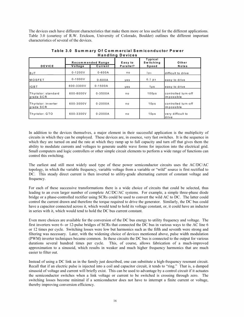
The devices each have different characteristics that make them more or less useful for the different applications.Table 3.0 (courtesy of R.W. Erickson, University of Colorado, Boulder) outlines the different importantcharacteristics of several of the devices.
T a b le 3 .0 S u m m a ry O f C o m m e rc ia l S e m ic o n d u c to r P o w e rH a n d lin g D e v ic e s
T yp ic a lR e c o m m e n d e d R a n g e E a s y to S w itc h in g O th e r
D E V IC E V o lta g e C u rre n t P a ra lle l? S p e e d N o te s
B J T 0 -1 2 0 0 V 0 -6 0 0 A n o 1 µ s d iff ic u lt to d r ive
M O S F E T 0 -1 0 0 0 V 0 -6 0 0 A y e s e a s y to d r iv e
IG B T 6 0 0 -3 3 0 0 V 0 -1 5 0 0 A y e s 1 µ s e a s y to d r iv e
T h y r is to r: s ta n d a rd 6 0 0 -8 0 0 0 V 0 -3 5 0 0 A n o 1 0 0µ s c o n tro lle d tu rn -o ffg ra d e S C R im p o s s ib le
T h y r is to r: in v e rte r 6 0 0 -3 0 0 0 V 0 -2 0 0 0 A n o 1 0µ s c o n tro lle d tu rn -o ffg ra d e S C R im p o s s ib le
T h y r is to r: G T O 6 0 0 -3 3 0 0 V 0 -2 0 0 0 A n o 1 0µ s ve ry d iff icu lt tod r iv e
0 .1 µ s
In addition to the devices themselves, a major element in their successful application is the multiplicity ofcircuits in which they can be employed. These devices are, in essence, very fast switches. It is the sequence inwhich they are turned on and the rate at which they ramp up to full capacity and turn off that gives them theability to modulate currents and voltages to generate usable wave forms for injection into the electrical grid.Small computers and logic controllers or other simple circuit elements to perform a wide range of functions cancontrol this switching.
The earliest and still most widely used type of these power semiconductor circuits uses the AC/DC/ACtopology, in which the variable frequency, variable voltage from a variable or wild source is first rectified toDC. This steady direct current is then inverted to utility-grade alternating current of constant voltage andfrequency.
For each of these successive transformations there is a wide choice of circuits that could be selected, thusleading to an even larger number of complete AC/DC/AC systems. For example, a simple three-phase diodebridge or a phase-controlled rectifier using SCRs could be used to convert the wild AC to DC. The latter couldcontrol the current drawn and therefore the torque required to drive the generator. Similarly, the DC bus couldhave a capacitor connected across it, which would tend to hold its voltage constant, or, it could have an inductorin series with it, which would tend to hold the DC bus current constant.
Even more choices are available for the conversion of the DC bus energy to utility frequency and voltage. Thefirst inverters were 6- or 12-pulse bridges of SCRs that connected the DC bus in various ways to the AC line 6or 12 times per cycle. Switching losses were low but harmonics such as the fifth and seventh were strong andfiltering was necessary. Later, with the widening choice of devices mentioned above, pulse width modulation(PWM) inverter techniques became common. In these circuits the DC bus is connected to the output for variousdurations several hundred times per cycle. This, of course, allows fabrication of a much-improvedapproximation to a sinusoid, which results in weaker and much higher frequency harmonics that are mucheasier to filter out.
Instead of using a DC link as in the family just described, one can substitute a high-frequency resonant circuit.Recall that if an electric pulse is injected into a coil and capacitor circuit, it tends to ring. That is, a dampedsinusoid of voltage and current will briefly exist. This can be used to advantage by a control circuit if it actuatesthe semiconductor switches when a link voltage or current to be switched is crossing through zero. Theswitching losses become minimal if a semiconductor does not have to interrupt a finite current or voltage,thereby improving conversion efficiency.

17
Still another approach is to omit the center DC link altogether. With the addition of a few more semiconductorswitches, we have a cycloconverter. This topology is described in section 6.2.4 and examples of its use arefound in paragraphs 4.1.2, 4.2.2, and 4.4.2.
3.7 Implementation of Variable Speed
Taking all the pieces weve discussed, we can now start tying them together to create different variable- speedtopologies. Well look at them in two general categories: partial power handling and full power handling.
In a full power-handling system, the entire variable power output of a conventional generator is fed to theassociated power-conditioning electronics module to be transformed to constant frequency at constant voltagefor injection into the local utility. Although no special requirements are placed on the generator, the powerelectronics must be sized large enough to handle the full system output continuously.
On the other hand, it is possible to install a wound rotor induction generator with slip rings or other means ofaccess to the rotor, and connect the rotor winding to the same type of power converter as the previous case. Inthis case, however, by appropriate gating of the switches in the electronic input circuits, the generator rotor canin principle be caused to run at any positive or negative slip rate. For small values of slip, the amount of rotorreal power involved is small so that the electronic converter hardware needs to be rated for only a small fractionof the total generator power. This means important cost savings.
It is not surprising, however, to learn that the amount of wound rotor power that must be handled is stronglydependent on the range of variable speed over which the system is designed to operate. For example, in thelimit of zero rotor speed, the generator becomes a transformer and power in or out at the stator is equal to powerout or in at the rotor.
3.7.1 Partial Power Handling
The variable-speed approaches discussed in this section all have one aspect in common: the rotor is connectedto external devices via slip rings or other means and only the current in the rotor is controlled to allow variable-speed operation. For example, at rotor speeds above synchronous speed for a wound rotor induction machine,electrical energy will flow into any electrical load connected to the rotor slip ring terminals. Increasing powerflows with increasing speed difference above synchronous. Conversely, as the turbine rotor speed falls belowsynchronous speed and the rotor is connected only to a passive circuit, the synchronous machine will become amotor and will drive the turbine as a large fan.
One of the simplest methods for the implementation of variable speed using an induction generator is by using adiode rectifier to change varying AC from the rotor to DC and then some form of inverter to convert the DCback to utility AC. (Power produced through the stator will be grid synchronous.) This so- called sliprecovery procedure was often used in elevators in the early twentieth century to recover some energy when anelevator car was descending. During the early 1980s, an application of this technology was tested on theMOD-0 at Plum Brook, Ohio. The rectifier in this application was a three-phase diode bridge feeding a DC bus.This DC energy was fed to the utility through a twelve-pulse inverter employing SCRs.
A more limited form of variable speed can be classified as variable slip. As we have seen, the current in therotor is induced by the rotation of the rotor in the magnetic field of the stator. This current always acts tooppose the torque of the generator. If one increases the electrical resistance in the rotor it becomes harder toinduce rotor current to flow. To maintain a constant torque, the speed of rotation of the rotor must increase toincrease the current flow and maintain the generator at the same point on its torque-rpm curve. (See section6.1.3 for more details.) Varying the rotor resistances through several different methods can thus allow forvariable speed by constantly changing the slope of this torque-rpm curve. Devices with low rotor resistance arelow in slip or stiff, and thus highly efficient. Devices that introduce high resistance have high slip and expendpower through resistive heating. Unless this heat can be used, these devices are electrically inefficient. Oneexample of variable speed using these principles is the early Russian Balaclava machine (circa 1930s) whichused a rheostat to adjust the resistance in the rotor. With the proper design, this resistance heating can berecovered for useful purposes such as hot-water heating or space heating.

18
Another more recent and sophisticated example of variable slip is the Vestas Opti Slip. In this design, theresistors and switching electronics are located on the rotor. These electronics are used to switch the resistors inand out of the circuit to change the rotor resistance. The unique feature of this design is the use of an opticalcoupling to the rotor to control the resistor switching. This optical coupling eliminates the need for costly andunreliable slip rings and brushes.
Variable-slip designs have somewhat limited variable-speed ranges. And, though these designs may beinefficient, they are normally only active when generator power is at a maximum and the control algorithm istrying to shed power. At this point efficiency is not a critical issue of operation.
A more efficient method of taking advantage of this varying slip is to find a way of converting the slip to powerand returning it to the electrical grid. An early form of this method was the cycloconverter. These devices donot use an intermediate DC rectifier or inverter. Instead, they allow variations in rotor rpm by providingvariable rotor excitation using a network of thyristor switches referenced to the grid frequency through controlcircuits. For small slip ranges (speed ranges) the cycloconverter does not have to handle large amounts ofpower and can be small. As speed ranges increase, to say 2:1, the cycloconverter must be large enough tohandle more of the total power output of the generator. At this point other methods become more efficient.This technique was applied on the Growian turbine described in section 4.2 as well as one version of the MOD-0 (see section 4.1) and the MOD-5B (see section 4.4). The output from these devices required heavy filtering,due to the poor quality of the output AC wave form. See section 6.2.4 for more details on the operation of acycloconverter.
As mentioned above, one can replace the passive resistor of a slip recovery system with an active powerelectronics module. It is then possible to inject a controlled current of appropriate frequency and phase into therotor windings. This allows control of the generator torque and thus the turbine speed both above and belowsynchronous, as well as control of the reactive power exported to the grid. An example is the AWT-26(Advanced Wind Turbines Inc.) which uses an Electronic Power Conditioning, Inc. converter employing siliconcontrolled rectifiers in a unipolar series resonant converter. (See section 4.10 for more details).
These are only a few of the better-known examples of partial-power-handling techniques.
3.7.2 Full Power Handling
The induction generator techniques we have discussed so far used a connection to the rotor to, in some manner,control or regulate the rotor currents. If all the external devices connected to the rotor slip rings mentioned inthe above paragraph were removed together with the slip rings, and the rotor winding leads shorted together, wewould have a conventional induction machine. If placed in operation, fluctuating winds could drive thegenerator rotor fast and slow. However, the strong magnetic field of the stator, which is provided by the utility,will resist this changing speed and will allow only a few percent variation in speed in the form of positive ornegative slip. By using appropriate power electronics to supply stator current, rather than rotor current, it ispossible to control generator torque as in the above case of partial power handling. The rotor of the generatorcan be a wound rotor with no external connections or a simple squirrel-cage induction generator.
The power electronics design is the key to this approach. One power electronics approach is to use an AC-DC-AC current link. This design uses semiconductor switches to convert the turbine (wild) AC to DC and DC backto utility AC at the grid. For instance, the wind turbine rotor is commanded to spin at the optimum rpm inrelation to the wind. A computer controller senses the wind and determines what frequency the stator voltageshould be for optimum operation of the turbine. The power switches can be switched on and off in rapidsequences to allow current to flow in such a way as to appear as a waveform of the necessary frequency. Onemethod for controlling this switching is pulse width modulation, in which current flow is controlled by thelength of time the switch is closed. In order for this to work efficiently, the switches must be capable of veryrapid actuation. With a DC current link, two sets of switching modules are set up, one either side of the DC link(one to control the frequency to the stator and the other to control the frequency of the lines output to the grid).One set of switches may be controlled based on wind speed input, and another set may be controlled based onthe grid frequency.

19
In the late 1980s, Kenetech Windpower (now Green Ridge Services Company) chose the AC-DC-AC currentlink converter and PWM control for the design of the KVS-33 wind turbine. This machine used two squirrel-cage generators connected to a single dual-output gearbox. The power electronics links were capable of600 amps at 1400 volts. Switching was accomplished using IGBTs and a PWM switching technique. Thecontrol algorithm was designed to control the torque of the generator and limit changes in the torque load. Thisarrangement provided for bi-directional power flow and would allow motoring the turbine as well as powerproduction. This machine is discussed in more detail in section 4.8.
Even though we described a number of different approaches to implementing variable speed in wind turbineswe have only touched the surface. We described several electronic switches. However, the number of circuitdesigns that can be developed using these devices is limited only by the imagination and understanding of thedesigner. Besides circuit designs there are other topologies (combinations of generator designs, powerelectronics circuits, and control strategies) for variable-speed operation that have been examined and tested inwind turbine designs. The potential number of combinations is almost infinite. In a report of this size, it isimpossible to provide a detailed explanation of all the possible methods or even describe all of the methods thathave been tested. But the number of different approaches that have been reduced to practice in one form oranother stretches into the hundreds. Please refer to section 6.0 for additional information on other designs orconcepts.
4.0 VARIABLE-SPEED MACHINE HISTORIES
Many manufacturers have developed variable-speed machines over the last few decades. There have beenmany production machines and an even greater number of prototypes or proofs of concept. Table 4.1 identifiesa number of these machines and the combinations of generators and power conversion methods that allowedthem to run in a variable-speed mode. The list is, however, far from complete. We focused here on machinesfor which well-documented public data exist. But it represents a general cross section of the different methodsfor allowing variable-speed operation. This database may expand as additional information becomes available.
4.1 NASA MOD-0 Plum Brook
4.1.1 History
The experimental wind turbine erected at the Plum Brook Station of the NASA Lewis Research Center nearSandusky, Ohio, holds an important place in the recent history of wind energy in the United States. The suddenrise in fuel costs during the 1970s precipitated the federal wind energy program, the administration of whichwas assigned to the Energy Research and Development Administration. One component of the program wasdirected toward investigating large (> 100 kW) wind turbines. This was the origin of the MOD series of windmachines that eventually culminated in the MOD-5B machine in Hawaii (described in Section 4.4).
The design and fabrication of the first of this series, the MOD-0, was assigned to the NASA Lewis ResearchCenter (LeRC) in Cleveland, Ohio. The LeRC Plum Brook field-testing facility 60 miles west of Cleveland andjust outside Sandusky, Ohio, had space and moderate annual wind and so was chosen for the test site. The firstiteration of this family was analyzed, designed, fabricated, and erected in 18 months. The nacelle was placedatop its 30-meter tower on September 3, 1975. The machine achieved an 80-KW output at 30 rpm on October23, 1975. Not surprisingly for a prototype machine, over the next 11 years many transformations of the originaldesign were conceived and tested. For example, the tower shadow created by the original lattice tower and itsopen stairway precipitated the substitution of a tubular steel tower. To add experimental flexibility, this towerwas mounted on elastic footings with adjustable spring constants in order to study resonances. Many differentrotors were tested including a single blade with a counterbalance.

20
4.1.2 Configuration
The original 100-kW synchronous generator was driven by a 45:1 gear ratio transmission and a 30-meter(125-ft), two-bladed, downwind, rigid-hub, full-span pitch-controlled rotor. Rated power of 100-kW wasachieved at the constant 40 rpm with a wind of about 8 meters per second (17.7 miles per hours). Eleven yearslater in 1985 after many data sets from many interesting modifications had been analyzed, the configuration forthe final test appeared.
The equipment for this variable-speed test had evolved to a 200 kilovolt-ampere (kVA) wound-rotor inductionmotor fabricated by the Bogue Electric Manufacturing Company. It was driven through the originaltransmission with an added V-belt coupling of step-up ratio 1.28:1. This drivetrain was driven by two14.3-meter (47-ft) teetered, wooden blades, each with 2 meters of pitchable tips. The three-phase generatorstator was connected directly to the utility. The generator rotor winding was connected to the utility through acycloconverter custom designed by the Westinghouse Electric Corporation. Because the cycloconverter couldsupply variable low-frequency, three-phase voltage to the generator rotor with either phase rotation, the systemcould operate either above, below, or at synchronous speed. Theoretically, this 0- to 45-Hz voltage rangesupplied by the cycloconverter could allow the system theoretically to turn at speeds from 450 to 3150 rpm.However, due to transformer voltage and generator mechanical load limitations, operation was limited tobetween 1440 and 2160 rpm. For less-than-rated winds, the control system regulated system speed bycontrolling generator torque and attempted to match electrical power to the utility to the power available in thewind at that instant. When the wind power exceeded rated value for the machine, the controller shifted to aconstant power output algorithm and controlled speed by pitching the blade tips.
To facilitate comparison of this variable-speed operation with an equivalent constant-speed system, thegenerator rotor could be switched from the cycloconverter to a set of resistors. This caused the generator tobecome, in effect, a squirrel-cage induction machine with slip of about 5%.
As a by-product of the analysis performed by the control system, it was possible to supply reactive power to theinterconnected utility. This feature could help support voltage on power distribution lines if requested by theutility.
4.1.3 References
1. Herrera, J.I. and Reddoch, T.W.; Testing Requirements for Variable Speed Generating Technology forWind Turbine Applications. Electric Power Research Institute (EPRI) AP-4590, Project 1996-22, finalreport, May 1986.
2. McDade, J., Ziemke, R., and Schmidt, W.; Variable Speed System Testing on the MOD-0 Wind Turbine,Sverdrup Data report (Internal Solar Energy Research Institute (SERI) Report, . January 1986-June 1986.
3. Herrera, J.I,. Reddoch, T.W., and, Lawler, J.S.; Experimental Investigation of a Variable-Speed,Constant-Frequency Electric Generating System from a Utility Perspective. DOE/NASA/4105-1, NASACR-174950, May 1985.
4. Herrera, J.I. and Reddoch, T.W.; Analysis of The Electrical Characteristics of a Westinghouse VariableSpeed Generating System for Wind Turbine Applications. SERI/STR-217-3133, DE88001139, February1988.
4.2 The Growian Variable-Speed Wind Turbine
4.2.1 History
One of the first very-large prototype wind turbines was initiated by funding provided by the Federal Republic ofGermany in 1977/1978. At the end of the 1970s, three German utilities formed Growian GmbH, a companywhose purpose was to specify, design, build, and test a large-scale wind energy conversion system (LS WECS).The name was derived from Grosse Windenergie-Anlage or Large Wind Energy Plant. The resulting 3,000-kWturbine was advanced for its time in that it featured a variable-speed drivetrain with power electronics and a100-meter (328-ft) teetered rotor with full-span pitch. In 1979 the designers set up a trade-off between asynchronous generator with a frequency converter in the stator circuit versus a doubly fed asynchronous(induction) machine with a frequency converter in the rotor circuit. The doubly fed system was chosen.
21
The wind machine test station at the Kaiser-Wilhelm-Koog in northern Germany was chosen for the installationlocation. During October 1982 the nacelle with its two bladed rotor attached was raised to the top of its100-meter (328-ft) tower. Regular testing began during the summer of 1983, which yielded confirmation of thepredicted power curve and power coefficient. The machine responded well to the control system and novibrations or resonances were observed. Testing continued through the Spring of 1987.
Early in the testing, cracks developed in the material of the highly stressed parts of the hub. Repairing theseproblems caused extended periods of downtime. After a total of 500 hours of intermittent operation, it wasdecided to end the tests in August 1987. It was dismantled during summer, 1988.
The data archived during the testing year has been thoroughly analyzed under the management ofIndustrieanlagen-Betriebsgesellschaft mbH, which tested a full Growian rotor blade in the early 1980s. Thisinformation has been valuable for the design of subsequent machines, such as the WKA 60.
4.2.2 Configuration
To summarize, the Growian was a 3-megawatt (MW), variable speed, downwind machine on a 100-m (328-ft)concrete tower. The 100-m (328-ft), teetered, two-bladed, rotor was fabricated from glass fiber around a steelspar. From the cut-in wind speed of 6.3 m/s (14 mph) up to the rated wind of 11.8 m/s (26 mph), the controlsystem attempted to hold optimum tip-speed ratio. Full-span pitch allowed power limitation to 3 mw for windsup to the cut-out speed of 24 m/s (53 mph). Nacelle mass was 240 metric tons (529,000 lbs) and its orientation(yaw) was actively controlled. The rotor speed could vary between 15.73 and 21.28 rpm.
Three modes of operation were initially considered. First was simple direct connection of a synchronousgenerator with DC field excitation to the utility (essentially constant-speed operation). Computer simulations ofoutput power fluctuations in turbulent winds immediately ruled out this mode. The two other modes consideredpermitted variable rotor speed and therefore the possibility for maximum power tracking. One mode used thejust-described synchronous generator, but fed its entire output to an AC/DC/AC chain consisting of a rectifier, aDC bus, and an inverter to the grid. However, the mode finally chosen was to use a synchronous generator witha three-phase slip ring fed rotor (essentially, a wound-rotor induction machine.) The rotor was fed using fieldorientation techniques from a power electronics frequency converter. Recall that field orientation uses controlof phase and amplitude of the generator rotor excitation to set real and reactive power output to the utilityindependently of each other. In spite of the slight additional cost, this was the system that was built andinstalled. The system has since been used as a model for many wind turbines.
4.2.3 References
1. Leonard, W.; Field Oriented Control of a Variable Speed Alternator Connected to the Constant FrequencyLine in Implementing Agreement for Co-Operation in the Development of Large Scale Wind EnergyConversion Systems: Second Meeting of ExpertsControl of LS-WECS and Adaptation of Wind Electricityto the Network. Scientific coordination by R. Meggle and R. Windheim; Published by Zentralbibliothekder Kernforschungsanlage Jlich GmbH, Jlich, Germany, 1979.
2. Warneke, O.; Application of a double-fed asynchronous generator in the Growian wind power plant,1985; Windkraft Journal (Germany, Federal Republic of) Vol. 5:4. Coden: WIJOD; pp. 164-166.
3. Warneke, O.; Use of a double-fed induction machine in the large GROWIAN wind energy converter.1983; Siemens Energietech (Germany, Federal Republic of) Vol. 5:6. Coden: SIEED; pp. 364-367.
4. Braun, D., Kloeppel, V., Marsch, G., Meggle, R., Mehlhose, R. Schoebe, B. Wennekers, R.; Windenergy converter GROWIAN II; Original Title: Windenergieanlage GROWIAN II. Corporate Source:Bundesministerium fr Forschung und Technologie, Bonn (Grmany, F.R.); Publication Date: April 1984,p. 148.
5. Koerber, F.; Final plans for the construction of GROWIAN. Interim final report; Corporate Source:Bundesministerium fr Forschung und Technologie, Bonn (Germany, Federal Repulic of); PublicationDate: December 1980, p. 89.
6. IEA Wind Energy Annual Report for 1988, NUTEK, Swedish National Board for Industrial and TechnicalDevelopment, Allmänna Förlaget, Kundtjänst, S-106 47 Stockholm, Sweden, pp. 30-31.

22
4.3 Bergey Excel
4.3.1 History
The Bergey Windpower Company, headquartered in Norman, Oklahoma, marketed its first variable-speed,utility-connected wind turbine in 1980. In 1983, the larger, 10-kW EXCEL wind turbine was offered, and inabout five years over 300 machines had been installed, usually on farms and ranches. The standard grid- tiedinstallation featured the EXCEL turbine, a power electronics unit that converted the variable-voltage, variable-frequency alternating current (wild AC) to direct current and from there back to utility alternating current.This is the classical AC-DC-AC system.
4.3.2 Configuration
The EXCEL aerodynamic rotor with its three fixed blades is attached directly to the generator rotor. Becausethis rotor carries the permanent magnet excitation for the generator, the stator windings can be stationary andmounted on the wind machine frame, thereby obviating the need for slip rings. The fiber- reinforced plasticblades are flexible around their longitudinal axes. This feature, together with special pitch weights at theoutboard leading edges, causes a change in pitch angle as rotor speed increases. Thus, the relatively high angleat stand-still provides higher starting torque; and, as rotor speed increases, the blades deflect toward flatterpitch, thereby allowing a higher tip-speed ratio.
The two-fold function of all wind turbine control systems is to harvest maximum wind energy in normaloperation, and to protect the machine from damage in winds above rated power. For the latter requirement, theEXCEL can capitalize on its furling control. Although its rotor is 7 m (23-ft) in diameter, it is still practical toorient this machine into the wind by using a tail. By design, the horizontal axis of rotation of the turbine rotordoes not intersect the vertical yaw axis of the whole machine. When the wind speed approaches dangerousvalues, the preceding axis offset causes the rotor generator combination to yaw out of the wind and the machineslows to moderate speeds. This yawing is possible because the tail is hinged to the main machine body.However, the hinge axis is inclined to the vertical so that as soon as the excessive wind gust has passed, agravitational restoring moment exists that returns the machine to its operating configuration.
To match the incoming wild three-phase AC power from the 38-pole permanent magnet generator to a single-phase utility line, a half-controlled, three-phase bridge is paired with a voltage-source line-commutated inverter.The SCRs in this bridge permit the control system to control the voltage level on the linking DC bus, and thus tocontrol the charge level of any batteries connected to it. The second purpose of this DC bus is to provide powerto the voltage-source inverter power electronics, which feeds power into the utility. Once again, the switchesprovided in this element are SCRs.
4.3.3 Reference
1. BWC Excel-R Windpower Generator Owners Manual and Parts List, Bergey Windpower Company,Inc., 2001 Priestley Avenue, Norman, Oklahoma 73069. 1983.
23
4.4 NASA MOD-5B Wind Turbine System
4.4.1 History
The MOD-5 program was originally conceived in 1980, and drew significantly on the MOD-0 and MOD-2programs. It was funded by DOE and managed by the Wind Energy Project Office of the NASA LewisResearch Center. The machine was installed at Kahuku Village, Oahu, and was first operational in July 1987.Early in 1988, operation of the turbine was transferred to Hawaiian Electric Incorporated. Later operation of theturbine passed to Makani Uwila Power Corporation (MUPC) and the machine was kept in serviceintermittently until late in 1996. At that time, due to financial difficulties, the machine was shutdown alongwith the rest of MUPC, all property of which passed to the property owner, Campbell Estates. With noprospects for continued operation of the machine, Campbell estates decided to disassemble and scrap themachine. Prior to this decommissioning, DOE/NREL salvaged the drivetrain gearbox and generator in July1998.
4.4.2 Configuration
The turbine consisted of a 97.5-m (320-ft) diameter, two-bladed rotor, with welded-steel blades, incorporatingpartial span hydraulic pitch regulation, in which the outer 16.8 meters (55 ft) of each blade could be controlledto limit rotor torque. Operation included an upwind teetered rotor, a hydraulically driven yaw system, and a103:1 step-up planetary gearbox to drive a wound rotor generator. The nacelle set atop a welded 58.2-m(191 ft) tubular tower, with a 61-m (200-ft) hub height. Cut-in wind speed was 5.4 m/s (12 mph), with cut-outat 27 m/s (60 mph). Rotor rpm varied from 12.9 to 17.3.
Power generation was accomplished with a four-pole, three-phase, 60-Hz, 4160-V, wound rotor inductiongenerator with secondary power recovery. The generator had a 3.5-MVA rating. Normal variable-speedoperating ranges ran from 1330 to 1780 rpm. The generator had a dynamic speed range capability of 1250 to1880 rpm, with a maximum survival speed of 2270 rpm.
Variable-speed and secondary power recovery was accomplished by a cycloconverter. This arrangementprovided for AC-AC variable-speed operation. The rotor was allowed to vary in rpm within a limited range.The thyristor switches within the cycloconverter were programmed to provide vector control of the air gap field.The switches were provided with a reference waveform for each generator phase (the grid frequency). Theresult of this method was a very rough waveform for each of the rotor phases. Extensive filtering was necessaryto produce an acceptable system output meeting IEEE-519 requirements. Introduction of IGBTs and othersophisticated high-power electronic switches allows for much-improved implementation of this technology.
4.4.3 References
1. MOD-5B Wind Turbine System Final Report, Volume II, Detailed Report. NASA CR-180897, March1988.
2. MOD-5B Wind Turbine System Concept and Preliminary Design Report. NASA CR-168047, September1982.
3. Spera, D.A., Miller, M.W.; Performance of the 3.2 MW MOD-5B Horizontal Axis Wind Turbine During55 Months of Commercial Operation in Hawaii. WindPower 92 Proceedings, American Wind EnergyAssociation 1992.
4.5 DOE/Sandia National Laboratories /U.S. Department of Agriculture 34 Meter, Vertical-AxisVariable-Speed Test Bed
4.5.1 History
Design of the 34 meter vertical-axis wind turbine (VAWT) was begun in 1984 by Sandia engineering staff.Design required approximately two years. Ohio State University provided aerodynamics design support.Fabrication and assembly of components required approximately one year. The machine was installed at theUSDA test site in Bushland, Texas, near Amarillo, and was dedicated in spring 1987. The machine included the

24
first laminar flow, stall-regulated airfoils for wind turbines. At the time, the blades were the largest multivoidextruded-aluminum airfoils ever built. The machine remained in operation from 1987 until its finaldecommissioning in June 1998.
4.5.2 Configuration
The machine consisted of a 34-m (121-ft) diameter rotor with a height-to-diameter ratio of 1.25. The rotor topwas 50 m (164-ft) above ground level. Rotor bottom was 7 m (23-ft) above ground level. The blades were56 m (184 ft) in length, using a stepped tapered-blade design, and were stall regulated. The central aluminumsupport tube was 3-m in diameter, 12.5-mm of thick, and supported at its upper end by three pairs of 63-mmsteel bridge strand cables at an angle of 35 degrees to the ground. The rotor, which drove a 700-kWtransmission, was rated at 500 kW at 37.5 rpm in a 12.5-m/s (28-mph) wind. The turbine ran in variable speedbetween 25 and 38 rpm.
Power generation was accomplished through a 625-kW-rated synchronous generator. The generator wascapable of operating between 288 rpm and 1900 rpm. Variable-speed operation was accomplished with acurrent source-load commutated inverter, also known as a DC current link frequency converter. This providedAC-DC-AC conversion.
4.5.3 References
1. Klimas, P.C., Dodd, H.M., Clark, R.N.; An Overview of the DOE/Sandia/USDA Vertical Axis WindTurbine Test Bed. WindPower87 Proceedings. American Wind Energy Association, 1987.
2. Ralph, Mark E.; Control of the Variable Speed Generator on the Sandia 34-Metre Vertical Axis WindTurbine. WindPower89 Proceedings. American Wind Energy Association, 1989.
3. Ralph, Mark E.; A Model of the 34-M VAWT Variable Speed Generator Control System, Windpower90 Proceedings. Wind Energy Symposium, American Society of Mechanical Engineers, 1990.
4.6 The Enercon E-40 Variable-Speed Wind Turbine
4.6.1 History
The Enercon Company of Aurich, Germany, has been fabricating and supplying industrial drive invertersystems in sizes from 0.5 to 500 kW since 1984. Depending on size and the time of introduction, they haveincorporated MOSFETs, IGBTs, and GTOs as switches in their products. As an application of their powerelectronics drives, Enercon designed and began to fabricate wind turbines in 1984. The first turbine, the E-16,was a variable-speed, fixed-pitch, 16 m (52.5-ft), 55 kW machine, of which 46 were installed. With the successof this model, in 1987 Enercon introduced the variable-speed, 18 m (59-ft), 80 kW E-18. About 150 of theseturbines were sold before the end of production in 1993.
Research and development on the E-32/300 also began in 1987. This is a 32-m (105-ft), 300-kW machinehaving both variable speed and variable pitch. These units began to be installed in 1989. By 1993 over 180machines had been installed some of which achieved capacity factors of 33% and annual energy capture of overa million kilowatt-hours (kWh).
4.6.2 Configuration
While the E-32 continued the design of the previous smaller E series, Enercon initiated a parallel design effortin 1987 with a new variable-speed machine. This 36-m (118-ft), 400 kW prototype (E-36) instituted a low-speed generator, which connected directly to the three bladed wind turbine rotor. Testing of this prototypebegan in March 1992. Achieving reasonable power in the designed speed range of 15 to 37 rpm, required a ringgenerator of about 4 m (13-ft) diameter.
The E-40, which followed as an augmentation of the E-36, is a 40-m (131-ft), 500-kW variable-speedmachine, using an 84-pole, salient-pole synchronous generator, which began to be marketed and installed inlate 1993.

25
4.6.3 References
1. IEA Wind Energy Annual Report for 1991. p. 55, NUTEK, Swedish National Board for Industrial andTechnical Development, Allmänna Förlaget, Kundtjänst, S-106 47 Stockholm, Sweden. 1992
2. Haller, Mark; A 500 kW Variable Speed Gearless Wind Turbine Generator for the American Market;Windpower94 Proceedings, American Wind Energy Association, 1994.
4.7 The Gamma 60 Variable-Speed Wind Turbine
4.7.1 History
In October 1986 ENEA (the Italian National Committee for Research and Development of Nuclear andAlternative Energies) signed a cooperative agreement with the AeritaliaFIAT Aviazione for Wind EnergyConsortium for the design and fabrication of a large, 60-m (197-ft), horizontal-axis wind turbine, rated at1500 kW. Funding was supplied from ENEA, the European Commission, and some other Italian organizations.The next March, ENEL (the Italian National Electricity Board) placed an order for the machine with Aeritalia,which acted as the prime contractor in the consortium. This prototype turbine was erected at the wind energytest site in the northwest corner of Sardinia. Prominent in the specifications was the requirement for broad-range variable speed (15 to 44 rpm), as well as teetering hub, fixed pitch, and power regulation through yawcontrol.
4.7.2 Configuration
The blade design was based on the WTS-4 blades made by Hamilton Standard. This allowed the sameequipment to be used for the Gamma 60 machine. Some modifications, such as shortening the blades andinstalling an internal bulkhead-type rib (to reduce the centrifugal loads due to air pressure at high speeds), wereagreed upon. The rotor was designed to withstand runaway speeds in case of loss of utility or generator.
The 1.5-m (4.9-ft) low-speed shaft disc brake was designed to be able to stop the machine from excessive speedor from some other emergency. The two-stage epicyclical gearbox has a gear ratio of 33:1.
A direct current link is used between the generator rectifier and the utility inverter because that type offrequency converter provides the required width of speed range, excellent torque control, and electric dampingof structural modes.
The control algorithm chosen had the usual two operating regions. In the first, which is commonly calledregion two, the control system attempts to maintain rotor speed proportional to the existing wind and therebyhold a constant tip-speed ratio. The second region, commonly called region three, is where power starts toexceed the rating of the turbine, so that speed must be limited aerodynamically. In this case, this is done byyawing. Unusual, however, for the Gamma 60, is another short region between the two already mentioned. Inthis region, the drivetrain torque limit has been reached; however, the generator and drivetrain power limit hasnot been reached. The control algorithm then allows the torque to decrease a small amount. The resulting rotoracceleration allows more power to be transferred until the generator power limit is reached. At this point,operation at the resulting higher-than-optimum tip-speed ratio is unimportant, because excess wind power isavailable anyway.
The power electronics is also capable of driving the generator as a motor. Accordingly, the gearbox wasconstructed to transmit torque in either direction.
4.7.3 Reference
1. IEA Wind Energy Annual Report for 1989, p. 48, NUTEK (Swedish National Board for Industrial andTechnical Development). Allmänna Förlaget, Kundtjänst, S-106 47, Stockholm, Sweden, 1989.
2. IEA Wind Energy Annual Report for 1992, p. 85, NUTEK (Swedish National Board for Industrial andTechnical Development). Allmänna Förlaget, Kundtjänst, S-106 47, Stockholm, Sweden, 1992.

26
4.8 KENETECH WINDPOWER KVS-33 Variable Speed
4.8.1 History
During 1987, EPRI conducted a feasibility study for an advanced variable-speed wind turbine design. In 1988,an industry consortium was formed (EPRI, Pacific Gas and Electric Company, and KENETECH) to proceedwith the development of the proposed advanced turbine. In 1990, Niagara Mohawk Power Corporation joinedthis consortium. Between 1989 and 1993, this effort led to the introduction of the KVS-33 variable speedturbine. The first prototype turbines (then called the 33-300) were installed in 1989. Twenty-two pre-production prototype machines were installed in Altamont Pass, California, in 1991. Between 1992 and 1996approximately 700 turbines were produced and installed in locations as divergent as New York, Crowley Ridge,Canada, Buffalo Ridge, Minnesota, Guadalupe Pass, Texas, and Costa Rica. 1995 saw the installation of thefirst KVS-45 prototype turbine in west Texas. In 1996, KENETECH was forced to file for bankruptcy, placingthe future development of the KVS-33 and related technologies in jeopardy.
4.8.2 Configuration
The KVS-33 is a three-bladed upwind system. The rotor is 33-m (108-ft) in diameter. Each blade is composedof laminated fiberglass using NASA LS-1 airfoils. The total rotor swept area is 855 m2 (9,200 ft2). Powerregulation is via full-span pitch control, using linear hydraulic cylinders. The system is yaw driven, with ahydraulic motor, planetary gear system, and hydraulic damping. A parallel shaft, dual- output helical gearboxdrives two squirrel-cage induction motors. The machine is designed to operate on truss or monotube towers inheights varying from 24- to 43-m (80 to 140 ft). Cut-in wind speed is 4.05 m/s (9 mph). Cut-out wind speed is29.25 m/s (65 mph).
The two, parallel, squirrel-cage induction generators are each rated at 150 kW. During variable-speedoperation, the generator outputs can run from 0 to 90 Hz. Each generator feeds its own dedicated 250 kVA,three-phase AC/DC/AC electronics converter programmed for vector field control. These converters consist ofsolid-state switching using IGBTs to perform rectification and inversion, to produce 60 Hz utility output.Control of the switches is via a PWM algorithm. The equipment can be converted to 50 Hz.
4.8.3 References
1. EPRI; Power-Electronic, Variable-Speed Wind Turbine Development: 1988-1993, A Summary of the33M-VS Wind Turbine Development Program Conducted by KENETECH. Windpower, Pacific Gas andElectric Company, Niagara Mohawk Power Corporation, and EPRI, EPRI Technical ReportTR-104738, Projects 1590-16 and 3062-02, 1995.
4.9 Nordic 400 Variable-Speed Wind Turbine
4.9.1 History
In July 1990, the Swedish State Power Board decided to install two 400-kW wind turbines on Basteviksholmen,which is a small islet near the village of Lysekil on the west coast of Sweden. One turbine was to be acommercially available machine to serve as a baseline for comparison. The other was to be the prototype of anew design from a newly formed company called the Nordic Wind Power Company. The complete, two-machine project was named the Lyse Wind Power Station.
A Bonus 450-kW Mk 2 machine was chosen as the comparison machine and was installed during June 1992.Nordic Wind Power completed the design of the advanced prototype machine, the Nordic 400, in Autumn,1991; it was installed in August 1992. Both machines were installed on a low, rocky ridge in theBastseviksholmarna harbor. The perennial wind fetch from the open North Sea was similar for both machines,so performance comparison is fair. The turbines are operated from the utility control center 70 kilometers (43.5miles) distant.

27
4.9.2 Configuration
The Nordic 400 weighs 28 metric tons (61,730 lbs), whereas the Bonus weighs 46 metric tons (101,400 lbs).When parked, the Nordic teetered rotor presents less solidity to extreme winds than the three-bladed Bonus.The Bonus is a constant-speed machine, whereas the Nordic machine is a variable-speed, stall- controlledturbine with a 35-m (115-ft) upwind rotor. The two teetering glass-fiber reinforced polyester blades haverotatable tips for emergency stopping. The range of variable-speed operation is from 20 to 39 revolutions perminute. Hub height is 40 meters (131 ft).
The 400-kW induction generator is driven by a Flenders planetary 40:1 gearbox. The electric power isprocessed through an ABB-designed AC/DC/AC line-commutated-type, power-processing converter fordelivery to the local utility. During one 7000-hour test period, the Nordic turbine produced 805 megawatt-hoursof energy.
4.9.3 References
1. IEA Wind Energy Annual Report for 1992. NUTEK, Swedish National Board for Industrial and TechnicalDevelopment. Liljeholmsvagen 32, S-117 86, pp. 120 121, Stockholm, Sweden, 1992.
2. IEA Wind Energy Annual Report for 199. NUTEK, , Swedish National Board for Industrial and TechnicalDevelopment, Liljeholmsvagen 32, S-117 86S-106 47 Stockholm, Sweden, p. 110, 1993.
3. IEA Wind Energy Annual Report for 1994. National Renewable Energy laboratory (NREL), 1617 ColeBoulevard, Golden, CO, 80401-3393, pp. 121, 124. USA, 1994.
4. IEA Wind Energy Annual Report for 1995. National Renewable Energy laboratory (NREL), 1617 ColeBoulevard, Golden, CO, 80401-3393, p. 130. USA, 1995.
4.10 Advanced Wind Turbines AWT-26 Variable Speed with Doubly Fed Generator
4.10.1 History
The AWT-26 variable-speed turbine is a modification of the AWT-26/27 configuration developed by AdvancedWind Turbines, Inc. The AWT-26 used the ESI-80, developed by Energy Sciences, Inc., of Boulder, Colorado,as a point of departure. Development of the AWT-26 began in 1990 under subcontract to the NationalRenewable Energy Laboratory. The first prototype machine was installed in Tehachapi, California, in February1993. Additional prototypes were installed between 1993 and 1995, culminating in the modified AWT-27.
The AWT-26 variable speed turbine was originally installed at the NWTC in August 1994. In its initialconfiguration, this machine was a standard AWT-26 with a squirrel-cage induction generator and a 57 rpmfixed-speed rotor. Beginning in summer 1996, this machine was converted for variable speed operation under asubcontract with Electronic Power Conditioning, Inc., with AWT as a lower-tier subcontractor. The machineconversion was accomplished by replacing the induction generator with a wound rotor generator and a powerelectronics package allowing variable-speed operations. At the conclusion of testing in 2000 the machine wasconverted back to fixed speed operation
4.10.2 Configuration
The NWTC AWT-26 is a two-bladed, downwind, free-yaw machine. It includes a 27-m (88.5-ft) teetered rotor.The blades are of wood composite design and incorporate SERI airfoils and passive stall control. Rotor controlis provided by aerodynamic, electromechanically activated tip brakes. The machine includes a redundantmechanical brake incorporated into the drivetrain which includes a planetary gearbox manufactured byFlenders. The gearbox incorporates two stages at fixed, specified ratios between 25 and 35 to 1. The ratioselected depends upon rotor diameter and the generator frequencies required. The machine is also providedwith a small mechanical yaw drive for unwinding the droop cable. A PLC controller provides control of themachine. The nacelle sits atop a 24.4-m (80-ft) tubular tower.

28
Power conversion is accomplished using a 325-kVA, wound rotor generator. This unit operates at 480 V and anominal 60 Hz. This is a doubly fed unit, in which variable-speed operation is provided by connecting the rotorwindings to a power electronic converter. Speed variation is accomplished by controlling the rotor windingcurrents. Power conversion is achieved using an electronics package incorporating both IGBTs and SCRs and asemi-resonant converter circuit that inherently soft switches.
4.10.3 References
1. Weigand, Claus H., Lauw, Dr. Hian K., Marckx, Dallas A.; Utility-Scale Variable-Speed Wind TurbinesUsing a Doubly-Fed Generator With A Soft-Switching Power Converter. WindPower96 Proceedings,American Wind Energy Association, 1996.
2. Lynette, Robert; Development of the WC-86 Advanced Wind Turbine. WindPower92 Proceedings,American Wind Energy Association, 1996.
3. McCoy, Timothy J.; Loads Measurements on the AWT-26 Prototype Wind Turbine. SED-Vol. 16, WindEnergy-1995, ASME, 1995.
4.11 Northwind 100
4.11.1 History
Design of the Northwind 100 began in early 1994 under a design subcontract between CERTEK and theNational Renewable Energy Laboratory Next-Generation Innovative Subsystem project. The original designconcept included a Permanent Magnet direct-drive generator. In 1996, due to the tragic death of the CERTEKprincipal (Ed Lucas), CERTEK withdrew from the project and Northern Power Systems (NPS) assumedresponsibility for executing the subcontract. NPS extended their collaborative effort to include the NASAAmes Research Center and the National Science Foundation. This joint collaboration was focused ondeveloping a high-reliability machine for remote and harsh environments. NPS was ideally suited to this effortdue to their long history of providing equipment for deployment at the South Pole and other marine and cold-weather environments. In 1998, the first of the NW 100 machines was deployed at a Vermont test site. Futureplans include installation of a machine at the National Wind Technology Center for certification in preparationfor applications in Alaska and Antarctica.
4.11.2 Configuration
The NW 100 is a 100-kW, three-bladed, upwind variable-speed machine. The unit is direct-drive. Thegenerator is a wound-rotor, salient-pole synchronous alternator that was designed by the Westinghouse ElectricCompany. Aerodynamic power is supplied through a 16.6-m (54-ft) stall-controlled rotor with blades providedby LM Glassfiber. Details of the variable-speed drive and control remain proprietary.
4.11.3 Reference
1. Migliore, Paul, Calvert, S.D.; U.S. Department of Energy Wind Turbine Development Projects.NREL/CP-500-26151, April 1999.
29
4.12 The Vertical-Axis Variable-Speed EOLE at Cap Chat, Canada
4.12.1 History
In the early 1980s, Hydro-Quebec and the National Resource Council of Canada began a joint venture todevelop a large-scale Darrieus turbine (VAWT). In 1983 a preliminary design was completed. By the end of1984, detailed design and fabrication subcontracts were awarded. Erection of the machine was finally completeby November 1986. Rotor fabrication was performed by Versatile Vickers shipyard in Montreal and shipped tothe site by barge. The machine was sited near the village of Cap Chat, in Quebec Province, on the south shoreof the St. Lawrence River. This site was chosen for its 8.5-m/s (18.9-mph) wind speed average at 60-m(197-ft), which represents rotor mid-height.
First rotation and grid coupling occurred in July 1987. The machine was commissioned in August of the sameyear and became fully operational in March 1988. The machine operated regularly under operator supervisionfrom 1988 until 1993, when it was shut down due to failure of the bottom bearing. During the five years ofoperation, the machine was run at power levels of up to 2.7 MW. During its lifetime it produced 12,740 MWhin 18,600 hours of operation. Over this period it maintained an availability of approximately 94%.
4.12.2 Configuration
The Eole machine was a vertical axis wind turbine 96-m (344-ft) in height. Its equatorial diameter was 64-m(210-ft), with a swept area of 4000-m2 (43,055-ft2). Two blades were employed in the design using NACA0018 airfoils of 2.4-m (7.9-ft) chord. The machine was designed as a direct-drive variable-speed machine. Thegenerator was 12-m (39.37-ft) in diameter and power conversion was achieved using a static- frequencyconverter with power factor controls. The rated speed was 14.25 rpm with a maximum power output of 3.8MW. Designed cut-in wind speed was 5.5 m/s (12.2 mph) and cut-out wind speed was 20 m/s (44.5 mph).However, these operational speeds and power output were not attained in operation due to structural resonancesthat were discovered during check-out. The final schedule that was selected combined variable-speed operationwith constant-speed operation according to the average wind. For winds from 6.5 to 8 m/s (14.5 to 17.8 mph),the machine ran in variable-speed mode from 7.9 to 9.8 rpm. For winds between 8 and 11.5 m/s (17.8 to 25.6 mph)the power electronics governed the machine to a constant speed of 11.35 rpm. Similarly, above 11.5 m/s(25.6 mph) the machine was governed to a constant speed of 13.5 rpm. The machine did operate up to 13.5 rpmwith a cut-out wind speed of 17 m/s (37.8 mph). Data acquisition systems were developed built upon VAWTsoftware from Sandia National Laboratories.
4.12.3 References
1. IEA Wind Energy Annual Report for 1987. NUTEK, Swedish National Board for Industrial and TechnicalDevelopment, p. 11, Allmänna Förlaget, Kundtjänst, S-106 47, Stockholm, Sweden, 1987.
2. IEA Wind Energy Annual Report for 199. NUTEK, Swedish National Board for Industrial and TechnicalDevelopment, p. 31, Allmänna Förlaget, Kundtjänst, S-106 47, Stockholm, Sweden, 1993.
4.13 The Danish Machine at Tvind
4.13.1 History
In Spring 1975, a boarding school in the village of Tvind near Ulfborg in the Jutland region of Denmarkdecided to construct and install a large wind turbine. Some of the reasons for this were that the project wouldprovide the students with practical experience to supplement their theoretical classes, the energy would be ahedge against the expected rise in heating oil prices, and the idea fit with the schools philosophy ofdecentralization. As this was early in the present era of wind turbine development, several ideas for the designof the machine were successively considered, found unsatisfactory, and dropped. For example, it had beenintended initially to supply supplementary heat to the school buildings by circulating water heated from a wind-turbine-driven churn. A conventional generator with eddy current brake for heating water piped to the nacellewas also rejected. Next, a direct-coupled, 48-pole synchronous generator was being considered for electrical

30
heating. However, at this point an eight-pole, 2200-kVA, synchronous generator and a 1200-kW gearboxbecame available at a reasonable price. Further consideration revealed that, although all the wind machineenergy could be used for heating in the winter, in the summer there would be an energy surplus.
Eventually it was decided that some of this power should be sold to the electric utility. Direct synchronizationof the eight-pole generator to the utility was not indicated for several reasons. For example, the 20-kilometer(km) (12.3-mile) utility distribution line was very weak. The transmission gear ratio was not optimal for thewind regime at synchronous speeds, and the turbine blades were limited to a narrow range of tip-speed ratios fordynamic reasons. Therefore, it was finally decided to connect to the electric utility through a frequencyconverter. This alleviated many of the above considerations, and would allow for variable-speed operation.
4.13.2 Configuration
As finally built, the Tvind Schools machine was provided with a three-bladed, downwind rotor having a 54-m(177-ft) diameter. The blade material was glass-fiber-reinforced epoxy of 4700 kilograms (10,364 lbs) mass perblade. The three-bladed rotor implied a rigid hub, which was at a height of 53-m (174 ft) on a concrete tower.Full-span pitch as well as the torque from the generator controlled the machine. The variable rotor speedranged from 14 to 24 rpm.
Although the generator was capable of more, the machine was rated at 900-kW. In keeping with its originalpurpose of providing space heating for the school, output power could be switched either to a 1600-m3
(56,503-ft3) water reservoir or to classroom radiators. At the same time, some power was directed to a 400-kWrectifier/inverter. For medium winds heating power was held constant, the frequency converter took up theremaining varying power.
The three-phase generator at rated power provided 3300 volts at the output, which was transformed down to400 volts for the frequency converter. Six bridge-connected, solid-state thyristors rectified this power onto theconstant current DC bus, which had inductors in both the positive and negative sides. This DC energy wasinverted using six more thyristors under six-pulse phase control. This 50 Hz output was then transformed up to10,000 volts for injection into the utility distribution line. Filters were installed between the inverter and theoutput transformer. Their two-fold purposes were to attenuate the fifth and seventh harmonics from the six-pulse inverter, and to supply some compensation for reactive power. This filter was able to provide 200 kVA ofreactive compensation. The frequency converter was designed and built by 12 students in a special coursegiven by The Laboratory of Electric Circuits and Machines at The Technical University of Denmark.
In approximately 50,000 hours of operation, this machine supplied about 1,000 megawatt-hours of electricenergy per year. By early 1993 the machines rotor had accumulated over 53 million revolutions. In 1997 itcelebrated its 20-year anniversary
4.13.3 References
1. Krabbe, Ulrik; The Electric Power Equipment for the Windmill in Tvind, pp. 25-33. In ImplementingAgreement for Co-operation in the Development of Large Scale Wind Energy Conversion Systems: SecondMeeting of ExpertsControl of LS-WECS and Adaptation of Wind Electricity to the Network. Scientificcoordination by R. Meggle and R. Windheim; Published by Zentralbibliothek der KernforschungsanlageJηlich GmbH, Jηlich, Germany, 1979.
2. IEA Wind Energy Annual Report 1993, p. 36, NUTEK, Liljeholmsv≅gen 32, S-117 86, Stockholm,Sweden, 1993.

31
Table 4.1. Summary of Features of Selected Variable-Speed Turbines
Wind Turbine Generator Description Power ElectronicsModules
Turbine Name Date ofFirst
Turning
Variable-SpeedRange(rpm)
*Class *Subclass StatorPole
Count
RectifierAC→ DC
*Link Type InverterDCAC
AWT-26 August1998
32 to 60 Induc WR 4 RotorTerminal-20→+20
Hz
Resonant Utility Output3φ, 480v, 60 Hz
IGBT
BergeyExcel
1983 0 to 350 Synch PM 38 ControlledSCR 3φBridge
300-v. DCVoltageSource
Linecommutated1φ, 240 v.
EnerconE-40
1993 15 to 37 Synch DC 84 NotAvailable
NotAvailable
NotAvailable
EOLECap Chat
July1987
7.9 to 13.5 Direct-DriveSynch
DC (Large) NotAvailable
NotAvailable
NotAvailable
Gamma 60 6/03/92 15 to 44 Synch DC 12 NotAvailable
DC 3φ
Growian Summer1983
15 to 21.3 Induc WR (na) Cyclo-Converter
(na)
KENETECHKVS-33
June1995
NotAvailable
Induc(Two)
Cage 4 PWM IGBT
DCVoltage
PWM IGBT
Plum BrookMOD-0
March1986
25 to 37.5 Induc WR20 4 3φ DiodeBridge
DCVoltage
12 pulseLine comm.
SCR
DOEMod-5B
July1987
12.9 to17.3
Induc WR 4 (na) Cyclo-Converter
(na)
Nordic 400 August1992
20 to 38 Induc WR 4 NotAvailable
DC GridCommutated
Northwind100
1998 NotAvailable
Synch WR 4 NotAvailable
NotAvailable
Line
Sandia34-m VAWT
Spring1987
25 to 38 Synch WR 4 6-pulseLine comm
SCR
DCCurrent
6 pulseLine comm.
SCR
Tvind54 M
1977 14 to 24 Synch3 kV
WR 8 3φ DiodeBridge
DC,Current
6-pulseLine comm.
Thyristor

32
*GLOSSARY FOR TABLE 4.1
CLASS
Rotating Machine:Either an electric motor or an electric generator (or alternator). Usually, the same machine canfunction in either capacity.
Synch: A rotating machine employing a rotor carrying a source of constant magnetic field, either frompermanent magnets or from a winding connected to a source of direct current. When such a machine isconnected to a utility grid either as a motor or a generator, the ratio of the grid AC frequency to themachine rotational speed is at all times a constant independent of load.
Induc: An induction rotating machine. A rotating machine whose principle of operation depends on inducedvoltages caused by the relative motion between the spinning magnetic field in the air gap andconductors on the spinning mechanical rotor.
Comm: A rotating machine (either AC or DC) that transfers energy to or from the spinning rotor by means of asegmented commutator and brushes. This combination usually functions as a mechanical rectifier.
SUBCLASS
Cage: Cage or squirrel cage describes the construction of the rotor of the traditional induction machine. Acylinder of soft iron has bars of good conducting metals embedded in its surface and parallel to its axisof rotation. These bars are all electrically connected together by being welded to conducting rings ateither end of the rotor cylinder. No external electrical connections are made to it.
WRnn: The wound rotor is an alternative to the more common cage rotor of induction rotating machines. Thenumerals (nn) that follow the WR designator (when present) give the maximum percent of the full loadpower of the induction machine, which must be handled by the associated power electronics.
DC: The traditional synchronous rotating machine has a rotor equipped with coils of wire wound on softiron cores, and usually fed from slip rings. When these coils are supplied with direct current, theyproduce constant radial magnetic fields alternating in direction around the circumference of the rotor.The number of magnetic poles is made to be the same as the poles of the corresponding stator. Thesurface of the rotor may be either perfectly cylindrical (round rotor) or supporting radically projectingpole pieces called salient poles.
PM: To simplify the design of the traditional synchronous rotating machine, a system of PermanentMagnets can be substituted for the rotor field windings. The resulting generator starts to developvoltage as soon as the rotor starts to turn. Because the field strength is not adjustable, these machinescannot readily control reactive power flow.
LINK TYPE
DC, Voltage:The voltage on the direct current bus for transferring energy from the generator rectifier to the inverterthat feeds the utility is controlled to a constant value. It is characterized by the presence of a capacitoracross the bus. The current in this link depends on demand.
DC, Current:The current in the direct current bus for transferring energy from the generator rectifier to the inverterthat feeds the utility is controlled to a constant value. It is characterized by the presence of an inductorin series with the bus. The voltage on the bus is not controlled.

33
Cycloconverter:See Figure PE-5 in section 6.2.4.
Resonant:If the link between the electronics of the variable-speed source and the inverter that supplies the load isformed from appropriately connected inductors and capacitors, then current in the link is caused toconsist of one or more sinusoidal oscillations. The advantage of this arrangement is that by propertiming, switching can occur at instants of zero voltage (ZVS) and/or zero current (ZCS) switching.(See section 3.6)

34
5.0 CONCLUSIONS: THE FUTURE OF VARIABLE SPEED
After examining the long history of wind technology, it is clear that variable-speed operation is the norm, notthe exception. In the new environment of grid-connected power, variable-speed operation has beenimplemented using a wide variety of power-conditioning technology. This report has documented many of thevariable-speed approaches that have been successfully implemented. Yet even with this wide range of methods,no consensus has been reached on the best technology approach. Cost of energy remains the driving force inwind energy deployment. There is a constant trade-off between equipment capital costs and gains in efficiency.For variable speed to become universally adopted and a clear economic winner, the added cost of powerelectronics required by most variable-speed designs must be clearly offset by the added energy capture,reduction in loads and other systems costs, and the added benefit of providing power conditioning for utilities.As power electronics designs improve and costs of manufacture come down, the balance may tilt in the favor ofvariable speed; this technology could come to dominate the future of wind energy technology.

35
6.0 POWER CONVERSION DESIGN DETAILS
6.1 Generators
As mentioned in section 3.0, this section repeats some of the electrical topics covered in the earlier body of thereport from a quantitative and much more technical point of view. The generator diagrams show first thegenerators internal connections followed by its equivalent electric circuit. The two blades of a symbolic windturbine rotor are shown connected to the rotating part of each generator.
6.1.1 The DC Generator
Based on the magnetic field excitation produced by the stationary part (the stator), there are two types of DCgenerators used in wind turbines. One uses permanent magnets (PM) to generate the field and the other uses afield winding, as can be seen in Figure DC-1. The latter needs direct current power to generate the field flux.On the other hand, the permanent magnet does not consume power to generate field flux. Thus, for the samearmature size, a PM generator is more efficient than a wound field generator. If the field winding is directlyconnected across the armature output terminals to obtain its power, it is called shunt excitation. If the fieldcurrent is controlled separately from the armature voltage, it is called separately excited. Other types ofexcitation are not discussed in this report. The armature winding (rotor) carries the armature current thatsupplies the load. The power generated by the generator is transferred to its load from the armature winding viacommutator and brushes. The power generated can be controlled by adjusting the field current of the generator.
(a)
PermanentMagnet
Battery Battery
Brushes
Battery
Field Winding
La RaLfRf
EaVf Vt
IaIf La Ra
Ea Vt
Ia
S N
Figure DC-1. Physical diagrams and equivalent circuits of DC machines(a) wound field excitation(b) permanent magnet excitation
(b)
S N
PermanentMagnet

36
The following are the steady-state equations that govern the DC generators in Figure DC-1. All quantities arereal scalars with non time varying values. Thus, the inductive components can be ignored. Units for the threegenerator constants (the Ks) are determined by their equations. Their numerical values are governed bygenerator geometry and can be determined by measurement.
φ = Kf If (d1)
If = Vf / Rf (d2)
Ea = Ke φ ωr (d3)Ea = Vt + Ia Ra (d4)
T = KT φ Ia (d5)Pout = Vt Ia (d6)
where Unitsφ = magnetic field flux WebersIf = current of the field winding AVf = voltage across the field winding VRf = field winding resistance ΩEa = emf generated in the armature Vωr = angular speed of the armature rad/secVt = terminal voltage of the armature winding V Ia = armature current ARa = armature resistance ΩT = electrical torque NmPout = output power WKT ,Ke , and Kf = constants of the DC generator
For a wind turbine generator, the output power and driving torque required are desired variables. Equation (d5)shows that torque control can be accomplished via controlling flux φ (field current) or by controlling armaturecurrent (Ia). With a constant voltage across the field winding, the field current is constant. Thus, a DC-DCconverter or rheostat is needed to control the field current (flux). Fortunately, the power required in the fieldwinding is generally very small for a good generator. The armature current can be controlled by setting the DCvoltage across the armature winding. To control this power with a battery load, we would need to install a DC-DC converter between the battery and the armature winding. A permanent-magnet generator can only becontrolled by adjusting the armature current.
6.1.2 The Synchronous Generator
A synchronous machine usually consists of a stator holding a set of three-phase windings, which supplies theexternal load, and a rotor that provides a source of magnetic field. This may be supplied either from permanentmagnets or from direct current flowing in a wound field. Examples of wound field synchronous generators canbe found on several large wind turbines such as the MOD-0 series, and several Enercon turbines. Permanent-magnet synchronous generators are commonly found in small direct-drive wind turbines. Fixed-speedsynchronous generators such as the early MOD series have very stiff characteristics, however, and may createunfavorable mechanical interaction with the wind turbine, thus affecting the gearbox, the main shaft torque, andbending moments. Variable-speed operation has remedied most of the drawbacks of the synchronous generatorin fixed-frequency applications.
As stated in section 3.0, the synchronous generator rotational speed is locked to its stator frequency. Theexpression relating the rotational speed in revolutions per minute, the number of magnetic poles in the machine,and the electrical frequency in hertz can be expressed as:
rpm = 120 x frequency/poles (s1)

37
Figure SM-1 shows two, three-phase, synchronous generators with their balanced utility loads together with theequivalent circuits for one of their phases. Note that the motor convention was used in assigning the positivedirection for current. (The current arrow flows out at the utility symbol.)
The equations presented below were derived under the assumptions that the machine was in steady state, thatthe machine model is linear over the range of the variables, and that the stator winding resistance is negligiblecompared to its reactance. Under the steady-state assumption, we will assume all non-constant electricalquantities vary sinusoidally in time. This allows us to employ phasors in the equations to represent them.Because phasors represent quantities that vary sinusoidally, they have both magnitude and phase. They can thusbe conveniently represented by complex numbers and as such are depicted here by boldface symbols. Thesame symbol in normal font represents magnitude only. We will assume that their magnitudes are given asRMS (root-mean-square) values. The non-varying DC electrical quantities are, of course, a special case ofRMS values.
[Note: Although it is nearly universal that a lower-case i is recognized by mathematicians as the symbol forthe square root of minus one, electrical engineers use lower case j instead. (cf. Eq. s4)]
φ = Kf If (s2)If = Vf / Rf (s3)Es = Ke φ ω (s3)Es = Vs - j Is Xs (s4)Pout = (3 Es Vs / Xs ) sin δ (s5)T = Pout /ωr (s6)
FieldWinding
Battery
(a) (b)
Field Winding
XsLfRf
EsVf Vs
IsIf
S N
PermanentMagnet
Es Vs
Xs Is
Utility or variable-speedelectronics
S NPermanentMagnet
Figure SM-1. Physical diagram and equivalent circuits of a synchronous machine(a) Wound field excitation(b) Permanent magnet excitation

38
where:Units
φ = field flux linking the armature webersIf = the current through the field winding AVf = the DC voltage across the field winding VRf = the field winding resistance ΩEs = internal emf generated in a phase Vωr = rotor angular speed (rotor radians/sec)ω = (p/2) ωr, electrical angular frequency (electrical radians/sec)f = electrical frequency = ω/2π hertzVs = terminal voltage of the stator winding VIs = stator current AXs = ωLs = inductive reactance of one phase of a stator winding Ωδ = Phase angle of phasor Es with respect to phasor Vs degreeT = electrical torque N-mPout = output power WKe ,Kf = constants of the synchronous generator
Examination of two different applications of a synchronous machine will illustrate the information contained ina phasor plot of the voltage equation, Es = Vs - j Is Xs (Eq s4). The first application is that of an overexcitedsynchronous motor, which means that the machine converts electrical energy into mechanical energy.However, as the internal magnetic field is very strong, the machine is exporting VARs (volt amperes, reactive)back to the utility.
We will choose the motor terminal voltage, Vs, to be the reference and plot it along the real axis in the complexplane. Angles measured counter-clockwise are positive. The assumption that the machine is a motor impliesthat there must be a component of the load current in the same direction as (in phase with) the terminal voltage.The overexcited assumption means that the other component of the current, which is normal to the voltage,must lead this voltage. Note as shown in Figure SM-2a, the load is drawing a current that is leading the voltageby about θ = 30°. As we are assuming the internal impedance of the motor is purely inductive, the voltage dropacross it will lead the current through it by exactly 90°. The magnitude of this voltage drop (as a sort of OhmsLaw for reactances) is equal to XsIs. Prefixing (multiplying by) j = sqrt(-1) rotates this voltage drop from thedirection of the current, I, to a phase angle that is 90° advanced.
Our original voltage equation implies that the sum of the internal emf, Es, and the voltage drop across theinternal impedance, equals the terminal voltage, Vs. The two voltage phasors do indeed add vectorially to equalthe terminal voltage, and the internal voltage drop does lead its current by a right angle. Thus, the phasordiagram conforms to the given equations.
IS
Figure SM-2a. Overexcited SynchronousMotor Phasor Diagram
θθθθ
δδδδγγγγ
VS
jXSIS
ES

39
The voltage equation just employed is most convenient for constant-frequency applications. However, if theequation is divided by omega, the system electrical angular frequency, the following equation, which isconvenient for variable-speed applications, results:
Ke φ = φ = φ = φ = Vs /ω - jIs Ls (s7)
Because only the magnitudes and not the phase of the terms were affected, the phasor representation of thisequation shown below has the same shape as the preceding diagram. Figure SM-2b illustrates that if theVs /ω term−the so called volts per hertz ratiois held constant, the relative phases of the voltages will remainconstant.
Figure SM-2b. Synchronous Motor PhasorDiagram for Variable Speed
The second example of a phasor diagram is that of an underexcited generator. Conceptually, it is possible toimagine that the field excitation of the previously described motor is gradually reduced to under-excitation, andat the same time, the retarding mechanical load on its driveshaft changed from retarding torque to a drivingtorque in the same direction of rotation. That is, if the motor load were changed into an energy source, wewould find that the phasor diagram of Figure SM-2a (above) would smoothly transform itself into the followingdiagram:
Is
Es
Vs
jXsIs
γγγγ δδδδ
θθθθ
Ke φφφφ
Vs / ω
Is
jLsIs
Figure SM-2c. Underexcited GeneratorPuasor Diagram

40
As before, the internal emf, Es, and the internal voltage drop across the generator impedance, jXsIs, add to equalthe applied voltage from the utility, Vs. However, now the component of the current phasor parallel to theapplied voltage (dotted horizontal line) is in the opposite direction. This means that energy is now flowing inthe opposite direction. Namely, mechanical energy from the generator shaft is flowing into the utility lines.The VAR component of current which is at right angles to the applied voltage (short vertical dotted line) nowlags that voltage by 90° thus showing that this machine is drawing lagging current or is consuming VARs fromthe utility. These two components make up the current phasor, Is. Note also that, because the direction of theapplied torque has reversed, the torque angle, δ, has crossed over the applied voltage and Es now leads it.
As in the motor example, the variable-speed phasor diagram in Figure SM-2d retains the same phase anglerelations as long as the volts per hertz ratio is unchanged.
The previous two examples can be seen to be special cases from the plot in the complex plane in Figure SM-3.If the applied voltage phasors (Vs) in the previous examples were plotted along the real axis below, the currentof the motor example would fall in the first quadrant, and the current from the generator example would fall inthe third quadrant. We would expect that weakening the field strength of the motor would move its currentphasor into the fourth quadrant, while increasing the generator field strength would move its current phasor intothe second quadrant.
Ke φφφφ
Vs / ωωωωIs
jLsIs
Motoringoverexcited
Generatingoverexcited
Generatingunderexcited
Motoringunderexcited
Vs
Is
The phasor of the stator current determinesthe operation of the synchronous machine.• In the first quadrant, the synchronous
machine operates as an over-excitedsynchronous motor.
• In the second quadrant, thesynchronous machine operates as anover-excited synchronous generator.
• In the third quadrant, the synchronousmachine operates as an under-excitedsynchronous generator
• In the fourth quadrant, the synchronousmachine operates as an under-excitedsynchronous motor
III
III IV
Figure SM-3. Phasor diagram of the stator current of a synchronous machine indifferent operational modes.
Figure SM-2d. Underexcited GeneratorPhasor Diagram for Variable Speed

41
6.1.2.1 Four Quadrant Drives
When a power electronics adjustable speed drive (ASD) is specified as being a four-quadrant drive, it canhandle all of the above four cases. Thus, such a drive could drive a wind machine as a large fan or accept itsenergy as a wind generator while simultaneously and independently controlling reactive power flow.
By continuing the same simplifying assumptions about linearity and neglecting stator losses, we can writemachine torque in terms of new variables. From (s5) and (s6):
T = (3 Es Vs /Xs )/ωr sin δ (s8)
Using the expression for internal emf (s3) and the relation between electrical and mechanical angular speed, onecan write:
T = [ KT φ (Vs /ω) / Ls ] sin δ (s9)
where:ωr = rotor angular frequency in mechanical rad/secKT = 3Ke p / 2p = number of generator poles
This expression is useful in that generator driving torque under variable-speed conditions will be constant if itsvolts per hertz is held constantother things being equal.
It also shows that the generator power angle, δ, depends on torque applied. This is illustrated in Figure SM-4.Note that, as the torque changes continuously from driving torque through zero to retarding torque, the torqueangle changes smoothly and monotonically from negative 90º to positive 90º In addition, outside of this range,the magnitude of the torque decreases so that if mechanical torque either increases or decreases beyond thisrange of torque angle, the generator or motor becomes unstable, will pull out of synchronism, and eitheraccelerate to probable destruction or stall, respectively.
The torque equation can be rewritten in another way:
T = (3 Es Is / ωr ) cos γ (s10)
where γ is the phase angle of the load current with respect to the internal emf phasor.
= KT φ Ιs cos γ (s11)
Generating region
Torque
δ
Motoring region
π/2
−π/2
π
−π
Figure SM-4. Torque characteristic of a synchronous machine as a functionof the power angle δδδδ

42
Equation (s9) can be used to control the torque speed characteristic of the generator when it is connected to avoltage source inverter. Equation (s11) can be used to control the torque speed characteristics of the generatorwhen it is connected to a current source inverter. In general, control of a synchronous generator requiresposition and speed sensors. The position sensor is required to adjust the angle between the voltage or currentand the main flux.
In some applications, a synchronous generator can have unique characteristics:- For a permanent magnet generator, Keφ is constant, while in a wound-field, synchronous generator
it is adjustable up to its rated value.- For a utility-connected synchronous generator, Vs / ω ω ω ω is constant.- For a synchronous generator connected to a diode bridge rectifier, the load presented is a resistive
load (unity power factor). θ =1800
- For a synchronous generator operated as a synchronous condenser, the terminal voltage Vs andstator current IS will be in quadrature (zero power factor). θ = - 900
- For a synchronous generator connected to a phase-controlled rectifier, the load presented will havean inductive component (Z =R + jωL).
6.1.2.2 Adjustable Speed Drive (ASD) Terminology
Voltage Source: An energy source in an electric circuit is called a voltage source if it can hold its designatedterminal voltage irrespective of the current being drawn from or fed to it. Approximations to perfect voltagesources are storage batteries for DC, or a utility connection for AC. For short periods of time in practicalcircuits, a charged capacitor approximates a voltage source.
Current Source: An energy source in an electric circuit is called a current source if it continues to supply itsdesignated current to that circuit irrespective of the voltage across its terminals. There are no simple examplesof isolatable current sources, although the high-voltage Van de Graf electrostatic generator behavesapproximately as a current source. In practical circuits, the electric current inertial effect of an inductanceapproximates a current source for a short time.
Current Source Mode: Most variable-speed operation is in the current source mode. The equation (s11) is usedto control the torque-speed characteristics. Both the magnitude of current Is and the angle γ can be controlled.For a wound-field generator, the field flux can also be used as a control variable. This control variable isnormally used in the flux-weakening region (high rpm). Different current source inverters (load commutatedinverters [LCI] or current-regulated pulse-width modulation [CRPWM]) can be used to achieve the same goals.
Voltage Source Mode: Most voltage source inverters operate on a volt/Hz (Vs/ω) basis. With a voltage sourceinverter, the PM synchronous generator can be controlled by adjusting the angle δ. If the volt/Hz ratio can beadjusted, then it can be used as an additional control variable. For a wound-field generator, the field flux canalso be used as a control variable. This control variable is normally used in the flux- weakening region (highrpm). Different voltage source inverters (square-wave VSI or PWM VSI) can be used to achieve the samegoals.
Battery-charging Mode: A diode bridge rectifier can be used to connect the synchronous generator to a battery.The terminal voltage is clamped to the battery voltage; thus, the volt/Hz ratio changes as the frequency changesin inverse proportion to the frequency. The battery load and the diode bridge are presented to the generator as aunity power factor load. The charging-current or the torque-speed characteristic of the synchronous generatorcan be controlled by adjusting the field current or the armature current. For a PM synchronous generator, thefield current cannot be controlled. The characteristic can be changed if the volt/Hz can be controlled. This canbe accomplished by inserting the DC-DC converter between the battery and the rectifier.

43
6.1.3 Induction Generator
Currently, the most commonly used generator in wind turbines is the induction generator. Several reasons forusing induction generators are:
- Low cost- Ruggedness- Operates with slip (i.e., with some speed elasticity)- Readily available in the market in many sizes- Mature technology
There are two kinds of induction generators used in wind turbines, squirrel cage and wound rotor. Presently,about 90% of utility-grid-connected wind turbines use squirrel-cage induction generators. The rotor is made ofsoft iron with shorted rotor bars of copper or aluminum. They do not need slip rings like a synchronous orwound rotor induction generator.
The physical diagrams of a squirrel-cage induction machine (SCIM) and a wound rotor induction machine(WRIM) are presented in Figure IM-1. The squirrel-cage induction machine has a shorted rotor; therefore, therotor current is not accessible. Although physically there is no electrical connection between the rotor andstator; the electrical characteristics of the rotor are affected by the stator through magnetic coupling.
With a wound rotor induction machine, the rotor is normally constructed as a three-phase winding with thesame number of poles as the stator. Three-phase slip rings (and brushes) are used to allow control of the rotorcurrent. A resistive load or a bi-directional power converter can be connected to the rotor winding throughthese three-phase slip rings.
6.1.3.1 Squirrel-Cage Induction Machine
Figure IM-2 shows the torque-speed characteristic of an induction machine in the motoring and in thegenerating region. The National Electrical Manufacturers Association (NEMA) has established a terminologyfor four classes of induction machines, Types A, B, C, and D. In most applications, type B induction machines(shown in solid line) are used because they give a good starting torque and good efficiency and power factor atrated output. Type D (shown in dashed line) is used when high starting torque is required. Type D has a higherrotor resistance.
StatorWinding
(b)Utility
Load orPowerConverter
Rotor WindingIs connectedexternally to aresistive load or toa power converter
Slip ringsandbrushes
Figure IM-1. Physical diagram of induction generator in WTG applications(a) Squirrel-cage induction machine(b) Wound rotor induction machine
(a) Utility or variable-speed inverter
Rotor windingshorted forsquirrel-cage IM

44
Typically, the operating region of an induction machine is below 50% of the peak torque. Thus, the operatingslip of an induction machine is low (slip < 2 %). Although the operating slip is very low, the inductiongenerator used in wind turbines has the advantage of giving more compliance than a synchronous generator.
6.1.3.1.1 Constant-frequency operation
The equivalent circuit of a squirrel-cage induction generator is shown in Figure IM-3. The parameters of anSCIM consist of stator resistance Rs, stator leakage reactance Xls, rotor leakage reactance Xlr', rotor resistanceRr', and magnetizing reactance Xm'. The primed-sign signifies that the equivalent circuit is referenced to thestator side. Thus, the primed-parameter and primed-variable are referenced values and not the actual values.Ideally, the resistances and the leakage reactances are zero and the magnetizing inductance is infinite. Inreality, the magnetizing inductance is about 20-50 times the leakage inductance.
Start-up (slip=1)
Type BTorque
Motoring region
Generating region
Speed
Synchronousspeed (slip = 0)
Type D
Figure IM-2. Torque-speed characteristic of an induction machine at fixedfrequency for two different types of machines.
Normal operating range
Ir'Rs
Vs
Xls
Em'
IsRr'/sXlr'
Im'
Xm'
(a) Constant Frequency
Rs/ω Ir'Llr'Lls
Em'/ωVs/ω
Is Rr'/(sω)
Im'
Lm'
(b) Variable Frequency
Figure IM-3. Equivalent circuit of a squirrel-cage induction generator.

45
During start-up, the slip is one and the rotor circuit branch presents a much lower impedance (almost shortcircuit) than the magnetizing branch. The starting current is about 5 to 8 times rated current. Although the rotorcurrent is large, the magnetizing current is small. As the rotor speed increases, the slip decreases. The totalimpedance of the induction machine increases; thus, the stator current decreases, and the magnetizing currentand the torque increases as shown in the torque-speed characteristic. The slip at which the peak torque occurs isapproximately:
From the equation above, the peak-torque slip can be increased by using a higher rotor resistance (design D).
6.1.3.1.2 Variable-frequency operation with voltage source mode
The application of variable-frequency operation in motor drives is very common. In variable-frequencyoperation, the common arrangement is to use one power converter connected to the generator to control itscharacteristics. Another power converter is used to transfer the power generated by a wind turbine to the utility.Between the two power converters, a DC bus or resonant tank (link) is used. It is preferable that the powerconverters be bi-directional to enable operation as a motor during start-up of the wind turbine. The inductionmachine used is the SCIM, although a WRIM can also be used. To analyze an SCIM in variable-speed mode,the equivalent circuit shown in Figure IM-3a is redrawn and is shown in Figure IM-3b. The voltage source andthe parameters of the induction generator are divided by the electrical angular frequency ω. The variable-frequency equivalent circuit is very similar to the equivalent circuit at a constant frequency (Figure IM-3a),except the voltage is replaced by the Vs/ω, the reactance is replaced by the inductance, and the slip is replacedby the slip-frequency (sω). Figure IM-4 shows the torque-speed characteristics of an SCIM connected to avariable-frequency source at constant volt/Hz. An example of a variable-speed SCIM for a wind turbine isshown in Figure UI-1 (Section 6.3). The characteristics of an induction machine in variable speed are similar tothe constant-frequency operation of an induction machine when connected to a constant Vs/ω source. At highfrequencies, the ω is large enough that the Rs/ω is negligible. Thus, the torque-speed characteristics can bedrawn as a set of curves shifted with frequency. In the lower-frequency region, Rs/ω cannot be neglectedbecause its size increases as ω decreases. If the Vs/ω is constant, the torque-speed characteristics of theinduction machine shrink (refer to curve T1,f1 in Figure IM-4). Many drives operate with constant Vs/ω, whichis commonly called constant volt/hertz. However, in the lower-frequency region, Vs/ω is boosted a little tocompensate for changes in Rs/ω.
From the torque-speed characteristics shown in Figure IM-4, an SCIM can be operated as a generator at anyspeed by controlling the frequency and keeping Vs/ω constant. At higher frequencies, there is a limit when thepower converter cannot further increase the voltage Vs. If the operation is to be continued by increasing thefrequency at constant voltage, the Vs/ω (volt/hertz) must be reduced. This is called the flux-weakening region.As a result, the torque speed characteristics are reduced as the frequency increases. In this region, a constantkVA operation is generally maintained.
Using an off-the-shelf voltage source inverter with constant volts/hertz ratio, an induction generator can becontrolled in a simple way. For example, given the wind turbine torque-speed characteristic (Twind turbine) thefrequency at operating points T1, T2 , T3, and T4 can be pre-computed. A map of frequency versus speed can bepre-programmed and the variable speed can be controlled with this pre-programmed path.
Slip peakR
R X Xr
s ls lr
_( )
'
'=
+ +2 2

46
6.1.3.1.3 Field-oriented control in variable speed
A modification of the equivalent circuit of Figure IM-3b is shown in Figure IM-5. It will be helpful to simplifythe analysis of the variable-speed SCIM in current source mode operation. Reference [1] provides goodinformation on this subject. With a current source, the phase angle and the amplitude of current Is can becontrolled independently at any frequency provided that the power converter is within the limit of its capability.The power converter uses current feedback to control the phasor Is. The power converter is controlled togenerate the command current. (Implementation of current sources is presented in section 6.2.3). Thesecurrents are controlled at any speed to have a certain torque (controlling Iqs) and at a rated flux (controlling Ids).Given the torque and flux component (normally the latter is kept constant at rated value), the slip frequency canbe computed. Thus, the torque-speed characteristics can be tailored accordingly. This flux-oriented control orvector control has been used very extensively in the drive industry since the early 1970s. Different controlstrategies can also be used to control the torque-speed characteristic.
Ls'Rs/ω
Vqds/ω
IqsIs
(Lm'/Lr')2 Rr'/(sω)Ids
(Lm' 2/Lr')
Figure IM-5. Modified equivalent circuit of a squirrel-cage induction generator toillustrate variable-speed implementation with current source
Iqs Iqr
IdsIs
λλλλds(a) (b)
Torque
Motoring region
Generating region
Twind turbine
T1
T2T3
T4
f4f3f2
f1
f1 < f2 < f3 < f4
Figure IM-4. Torque-speed characteristic of an induction machine in variablefrequency at constant volt/hertz operation.
Motor torque shrinksat low freq.
Generator torqueincreases at low freq.
RotorSpeed

47
The following equations can be used:
s ω = (Rr' /Lr') (Iqs/Ids)T = KT Iqs Ids
where KT is constant, Ids is generally kept at rated (except in a flux-weakening region), and Iqs is specified basedon torque requirement. The slip frequency is computed.
6.1.3.2 Wound rotor induction machine with resistive load control
The physical diagram of the WRIM can be illustrated in the previous Figure IM-1b. The characteristics of thewound rotor induction generator are shown in Figure WRIM-1. In this machine, three-phase slip rings aremounted on the rotor shaft. The slip rings can be connected to a three phase passive adjustable resistance or athree-phase power converter. The stator is connected to a constant-frequency (60-Hz) utility supply. Thetorque speed characteristic can be changed by inserting different values of external rotor resistances Rex. Forexample, installing R1 will make the slope lower and installing R2 will make the slope even lower. In windturbines, this adjustable rotor resistor control (a Rheostat) was used as early as 1930 in Yalta, USSR. Withrheostat control, at start-up (motoring mode) the rheostat can be set to R2. Then, when the generator startsgenerating, the rheostat is controlled to R1 or it can be shorted completely. Although the torque-speedcharacteristics can be changed by the operator, there are additional losses associated with external resistors.
The additional losses are proportional to:
P_extra_loss = 3 Ir'2 Rex'
These extra losses are converted into heat that must be dissipated, preferably outside the generator frame so thatthe heat loss does not increase the winding temperature. The concept of a rheostat can be extended by using apower converter to adjust the resistive load presented (apparent Rex') to the rotor winding which can beaccomplished by using a three-phase diode bridge and a DC-DC converter with a resistive load connected onthe DC bus. Thus, by controlling the duty ratio of the DC-DC converter, the fictitious rheostat can be
Soft start (Rex' is continuously varied from R2 to 0.
Constant torque (Rex' is varied)
Constant power (Rex' is varied)
Torque
Motoring region Generating region Speed
Constant torque mode
Rex' = 0
Figure WRIM-1. Torque-speed characteristic of a WRIM with the resistive loadis adjusted by power converter to vary the apparent Rex.
Constant power mode
Rex' = R1
Rex' = R2
R1 < R2

48
continuously controlled. This power electronics adjustable resistor has been implemented by Vestas with theirproduct called Opti-slip. Again, we can generate a map of duty ratio versus rotor rpm. Thus, with the rotor rpmas the feedback, the duty ratio is controlled continuously to give:
- Soft start-up capability (dashed line in the motoring region)- Constant power generation (solid line in the generating region)- Or constant torque generation (dotted line in the generating region).
In some WRIM systems, the resistive power in the rotor is returned to the utility. A combination of three- phasediodes and three-phase line-commutated inverters is used. In this system, the P_extra_loss shown above isreturned to the utility (MOD-5B). The torque-speed characteristic can also be mapped and used to control thetorque or power.
When the direction of power is coming out of the rotor, the generating region starts only above synchronousspeed. The equivalent circuit used to describe the system is shown in Figure WRIM-2a. Normally, the pitchcontrol is used to limit the speed of the wind turbine once the power limit or torque limit is achieved. Thephasor diagram related to this system can be illustrated in Figure WRIM-3a. It can be shown that the outputpower at the stator side will always be inductive (lagging or under-excited), as shown in Figure WRIM-3a,because there is no compensation in the rotor circuit.
6.1.3.3 Doubly fed WRIM with power electronics driven rotor.
For a doubly fed wound rotor induction machine, the stator is connected to a three-phase, constant- frequencysupply and the rotor is connected to a three-phase, variable-frequency power converter. The doubly fed WRIMequivalent circuit is shown in Figure WRIM-2b. Two methods for connecting a variable speed WRIM to autility are shown in Figure WRIM-5. The frequency fed to the rotor winding is proportional to the slip timesthe stator frequency, and the voltage across the rotor winding is determined by the stator voltage, the slip, andthe turns ratio of the rotor-to- stator winding. In order to lock the phase angle between the voltage of the stator,the stator voltage must be referred to the rotor side. This requires knowledge of the turns ratio, the slip, and the
Figure WRIM-2. Equivalent circuit of a wound rotor induction machine(a) Resistive load control (b) Doubly fed operation.
LlsRs/ω Ir'Is Rr'/(sω)Llr'
Em'/ωVs/ω
Im'
Lm'Er'/ωor Ir'
(b)
XlsRs Ir'IsRr'/sXlr'
Em'
Im'
Xm' Rex'/s
(a)
Ir'
Ir'
Im'Im'Is
Is
VsVs
φr' φr'
Figure WRIM-3. Phasor diagram of two different rotor controls(a) Resistive load control (b) Doubly fed operation.
(a) (b)
RotorSpeed
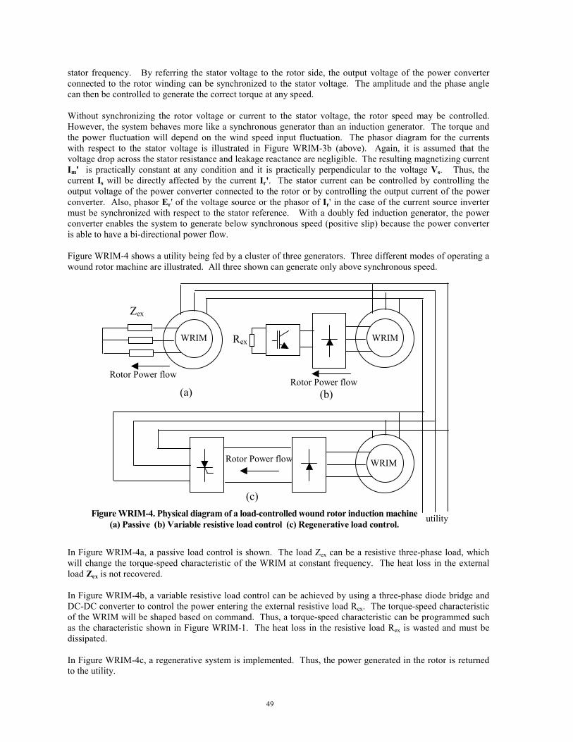
49
stator frequency. By referring the stator voltage to the rotor side, the output voltage of the power converterconnected to the rotor winding can be synchronized to the stator voltage. The amplitude and the phase anglecan then be controlled to generate the correct torque at any speed.
Without synchronizing the rotor voltage or current to the stator voltage, the rotor speed may be controlled.However, the system behaves more like a synchronous generator than an induction generator. The torque andthe power fluctuation will depend on the wind speed input fluctuation. The phasor diagram for the currentswith respect to the stator voltage is illustrated in Figure WRIM-3b (above). Again, it is assumed that thevoltage drop across the stator resistance and leakage reactance are negligible. The resulting magnetizing currentIm' is practically constant at any condition and it is practically perpendicular to the voltage Vs. Thus, thecurrent Is will be directly affected by the current Ir'. The stator current can be controlled by controlling theoutput voltage of the power converter connected to the rotor or by controlling the output current of the powerconverter. Also, phasor Er' of the voltage source or the phasor of Ir' in the case of the current source invertermust be synchronized with respect to the stator reference. With a doubly fed induction generator, the powerconverter enables the system to generate below synchronous speed (positive slip) because the power converteris able to have a bi-directional power flow.
Figure WRIM-4 shows a utility being fed by a cluster of three generators. Three different modes of operating awound rotor machine are illustrated. All three shown can generate only above synchronous speed.
In Figure WRIM-4a, a passive load control is shown. The load Zex can be a resistive three-phase load, whichwill change the torque-speed characteristic of the WRIM at constant frequency. The heat loss in the externalload Zex is not recovered.
In Figure WRIM-4b, a variable resistive load control can be achieved by using a three-phase diode bridge andDC-DC converter to control the power entering the external resistive load Rex. The torque-speed characteristicof the WRIM will be shaped based on command. Thus, a torque-speed characteristic can be programmed suchas the characteristic shown in Figure WRIM-1. The heat loss in the resistive load Rex is wasted and must bedissipated.
In Figure WRIM-4c, a regenerative system is implemented. Thus, the power generated in the rotor is returnedto the utility.
Rex
Zex
(a)Rotor Power flow
Rotor Power flow
WRIMWRIM
(b)
(c)
Rotor Power flow WRIM
utilityFigure WRIM-4. Physical diagram of a load-controlled wound rotor induction machine(a) Passive (b) Variable resistive load control (c) Regenerative load control.
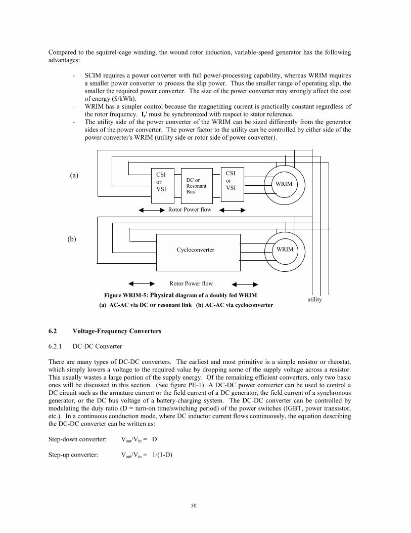
50
Compared to the squirrel-cage winding, the wound rotor induction, variable-speed generator has the followingadvantages:
- SCIM requires a power converter with full power-processing capability, whereas WRIM requiresa smaller power converter to process the slip power. Thus the smaller range of operating slip, thesmaller the required power converter. The size of the power converter may strongly affect the costof energy ($/kWh).
- WRIM has a simpler control because the magnetizing current is practically constant regardless ofthe rotor frequency. Ir' must be synchronized with respect to stator reference.
- The utility side of the power converter of the WRIM can be sized differently from the generatorsides of the power converter. The power factor to the utility can be controlled by either side of thepower converter's WRIM (utility side or rotor side of power converter).
6.2 Voltage-Frequency Converters
6.2.1 DC-DC Converter
There are many types of DC-DC converters. The earliest and most primitive is a simple resistor or rheostat,which simply lowers a voltage to the required value by dropping some of the supply voltage across a resistor.This usually wastes a large portion of the supply energy. Of the remaining efficient converters, only two basicones will be discussed in this section. (See figure PE-1) A DC-DC power converter can be used to control aDC circuit such as the armature current or the field current of a DC generator, the field current of a synchronousgenerator, or the DC bus voltage of a battery-charging system. The DC-DC converter can be controlled bymodulating the duty ratio (D = turn-on time/switching period) of the power switches (IGBT, power transistor,etc.). In a continuous conduction mode, where DC inductor current flows continuously, the equation describingthe DC-DC converter can be written as:
Step-down converter: Vout/Vin = D
Step-up converter: Vout/Vin = 1/(1-D)
Rotor Power flow
(b)
Rotor Power flow
WRIM
utility(a) AC-AC via DC or resonant link (b) AC-AC via cycloconverter
Cycloconverter
(a)DC orResonantBus
CSIorVSI
CSIorVSI
WRIM
Figure WRIM-5: Physical diagram of a doubly fed WRIM

51
6.2.2 AC-DC Power Converter
The device for converting AC to DC is called a rectifier. Figure PE-2 shows two types of rectifiers. The three-phase diode bridge and the three-phase, phase-controlled rectifier both convert AC to DC. The output of adiode bridge cannot be controlled; however, the phase-controlled rectifier output can be controlled by adjustingthe firing angle ( α ) of the silicon-controlled rectifier.
The input-output relationship for a continuous conduction mode can be written as follows:
Three-Phase Rectifier:
Phase-Controlled Rectifier:
While the DC load connected to the diode rectifier is presented as a resistive (R) load to the generator, the sameload connected to a phase-controlled rectifier is presented as an adjustable inductive (RL) load to the generator.The adjustable firing angle presents a time delay or lagging current with respect to the voltage. Thus, thegenerator characteristic is affected in different ways when connected to a diode rectifier or phase- controlledrectifier because the output of the diode rectifier is not adjustable, a DC-DC converter is normally placed inseries with the diode bridge. Examples of applications include synchronous machine field winding control,charging current control in battery charging, DC bus control, and heater control.
V Vdc LL= 32
π
V Vdc LL= 32
παcos
+
-
+
-
Step-down converter
Step-up converter
or
or
Battery, DC armature or field winding
Battery, DC armature or field winding
Vin
Vin
Vout Vout
Vout
+
-
-
+
Power flow
Power flow
(b)
(a)
Figure PE-1. DC-DC converter to change one DC level to anothera) Step-down converterb) Step-up converter

52
The current on the AC sides for both diode bridge and phase-controlled rectifiers is not sinusoidal. If the ACsides are connected to the utility, the harmonic currents should be corrected to limit the harmonics withindefined limits. If the AC side is connected to the generator, the non-sinusoidal current may generate torquepulsations and increase the heat loss generated by harmonic currents.
6.2.3 DC-AC Power Converter
The device for converting DC to AC is called an inverter. In the early development of power inverters, SCRswitches were used. The SCR is a rugged power switch that can be turned on when the voltage across it isforward biased. However, in order to turn off the SCR, a commutation circuit is needed. With the advent ofpower electronics, faster switches such as power transistors, IGBTs, and power MOSFETs are used. (SeeTable 3.0, section 3.5 in this report.) The devices can be turned on and off any time by applying the correctsignal on the base drives. In Figure PE-3a, a generic three-phase inverter is shown. IGBTs replace the SCRsfrom early inverter generations. The diodes parallel to the power switches are called freewheeling diodesbecause they allow the current to continue to flow in the inductance when the power switches (IGBTs) areturned off. The circuit shown in Figure PE-3a is a typical voltage source inverter converting DC to AC, wherethe switches are turned on and off to imitate sinusoidal voltage. In the early stages of development, a six-step,square-wave voltage source was used. A typical per-phase voltage across the load is shown in Figure PE-3b.The frequency of the square-wave can be changed to adjust the speed or the power of the electric machine. Theamplitude, which depends on the amplitude of the DC bus voltage, can also be adjusted by adjusting DC busvoltage. Thus, a volt/hertz ratio can be created. One drawback of this type of inverter is the resulting current isnon-sinusoidal. In a conventional electric machine, only the fundamental component of the stator currentgenerates useful torque. The harmonic components create torque pulsations and additional losses.
In more modern designs, PWM techniques are used to turn the power switches on and off. Many concepts havebeen developed around PWM techniques to generate output with lower harmonics. The sine-triangularcomparison is a classical one that compares the sine wave (at the fundamental frequency requested) to atriangular wave (at the selected switching frequency). With this technique, the magnitude and the frequency
+
-
(a)
+
-
(b)
Power flow Power flow
Vdc Vdc
VLLVLL
Figure PE-2. Three-phase rectifierb) Three-phase diode bridge rectifier
c) Three-phase phase-controlled rectifier

53
can be modulated with a constant DC bus. A higher switching frequency can generate a smoother current waveform but higher switching losses. A balance between efficiency and performance is important in making a finaldecision. However, with faster switches used in the power converter, the issue of switching losses becomes lesssignificant.
Another way to control a three-phase inverter is to control the output current of the inverter. In earlydevelopments, a line-commutated inverter was used to return the power generated by the wind turbine to theline supply. Or a load-commutated inverter was used to control a variable-speed synchronous generator. Thistype of inverter is shown in Figure PE-4a. With an LCI, the current can be controlled in frequency, magnitude,and phase angle. The power converter uses SCRs for the power switches. SCRs are available in high powerratings. Although these power converters work very well, the resulting current presented to the three-phase sideis non-sinusoidal. In an LCI, the non-sinusoidal current generates torque pulsations (especially at lowerfrequencies) and other harmonic-related losses. At the utility side, the line-commutated inverter is controlled toreturn the power to the utility at constant frequency. The drawback of using a line-commutated inverter toreturn the power to the utility is that the power factor is not controlled (non-unity power factor) and theharmonic content is high. Some filtering may need to be included in the utility system to reduce the harmonicsgenerated to the utility. Some systems use zigzag transformers and dual converters to create a twelve-pulseinverter.
With faster switches available, CRPWM are used. The power converter behaves like a highpower amplifier,which shapes the output current based on the commanded current. A current template is needed to shape theoutput current and this commanded current is compared to the actual current from the current sensor. Thecurrent controller turns on and off the correct switch (top or bottom) of the corresponding phase. The circuitdiagram of the three-phase current inverter is shown in Figure PE-4(b) below. Only the controller for phase Ais shown. The other phases are controlled in the same fashion. Note that in the current controlled inverter, thephasor Ia, Ib, and Ic can be instantaneously controlled in its magnitude, frequency, and its phase angle. Ingeneral, speed sensors are also needed at the generator to determine the stator currents, frequency, and phaseangle to produce commanded torque.
+
-
Vs
Is (b)
(c)
Power flow Lf Rf
(a)
Figure PE-3. Three-phase voltage source invertera) Circuit diagramb) Per phase voltage of a square-wave inverterc) Per phase voltage of a PWM inverter
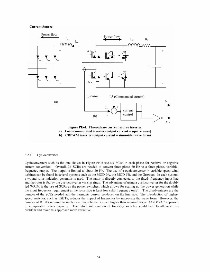
54
6.2.4 Cycloconverter
Cycloconverters such as the one shown in Figure PE-5 use six SCRs in each phase for positive or negativecurrent conversion. Overall, 36 SCRs are needed to convert three-phase 60-Hz to a three-phase, variable-frequency output. The output is limited to about 20 Hz. The use of a cycloconverter in variable-speed windturbines can be found in several systems such as the MOD-0A, the MOD-5B, and the Growian. In each system,a wound rotor induction generator is used. The stator is directly connected to the fixed- frequency input lineand the rotor is fed by the cycloconverter via slip rings. The advantage of using a cycloconverter for the doublyfed WRIM is the use of SCRs as the power switches, which allows for scaling up the power generation whilethe input frequency requirement at the rotor side is kept low (slip frequency only). The disadvantages are thenumber of the SCRs needed and the harmonic current produced on the line side. The introduction of higher-speed switches, such as IGBTs, reduces the impact of harmonics by improving the wave form. However, thenumber of IGBTs required to implement this scheme is much higher than required for an AC-DC-AC approachof comparable power capacity. The future introduction of two-way switches could help to alleviate thisproblem and make this approach more attractive.
Current Source:
+
-
Power flow
currentcontrol
Ia* (Commanded current)
Ia +
-
Ia sensorA+
A -
A+
A -
Lf Rf
Power flow
Idc
+
-
Lf
Figure PE-4. Three-phase current source invertera) Load-commutated inverter (output current = square wave)b) CRPWM inverter (output current = sinusoidal wave form)
(a)
(b)

55
6.3 Utility Interface
At the utility side, the power generated by the wind turbine must be transferred to the utility at constantfrequency. With a line commutated inverter connected to the utility, the current wave form will be non-sinusoidal and some kind of filtering will be required. The process of generating electricity from a wind turbinerequires a source of power and a sink for power. One example of a wind turbine system is shown below.CRPWM can be employed at both the source side (wind turbine generator) and the sink side (utility). Thepower balance must be maintained.
Three phasevariable frequencyoutput (up to about20 Hz output).
Three-phase fixedfrequency input (60 Hz)
Figure PE-5. AC-AC conversion through a cycloconvertera) Circuit diagramb) Sample of output voltage
(a)
(b)

56
Power balance requires that:
Power generated at the source = Power transmitted to the sink + Losses
If the power generated is higher than the power transmitted and losses, the energy will go to energy storage(in this case, the DC capacitor shown). As a result, the DC bus voltage will increase. On the other hand, if thepower returned is larger than the generated power, the DC bus voltage will decrease. This power balanceconcept must be implemented in the controller to keep the system stable. With the power conversion shownabove, the torque-speed characteristics of the generator can be controlled at any rotor speed and the powerquality at the utility side can be maintained. The power conversion described above uses CRPWM on bothsides. Thus, at the generator side, a torque or power control can be commanded at any time and with a goodsinusoidal wave form, the generator torque will be smooth. (Refer to Section 6.1.3.1.3) At the utility side, thecurrent wave form can be commanded to have an adjustable power factor at minimum current distortion whilemaintaining the DC bus voltage constant (power balance).
7.0 A LOOK AT FUTURE DEVELOPMENT
A quick review of the preceding history of wind energy technology, shows that wind energy engineers anddesigners have long been aware of the implicit natural difficulty of matching a wind driven prime mover to autility connected electric generator. A century of electric technology development has yielded electricmachines with outstanding energy conversion efficiency, but are optimized to operate at exactly one speed. Onthe other hand wind driven machines whose power is based on the lift derived from airfoils have optimalperformance when their angle of attack is a relatively constant near a known optimum value. For this to be truefor a wind turbine airfoil the optimal rotor speed must be proportional to the impinging wind speed, an entitywell known for its variability.
As the preceding material has shown, there has been a remarkable diversity of solutions offered to amelioratethis mismatch. So far, rather than modifying mechanical transmissions or designing novel types of electricgenerators, system designers have coupled the variable electrical energy from traditional generators to the clientutility through a great variety of power electronic networks. The elements chosen to comprise such networkshave depended on the state of the electronic art at the time the system was built. Early on when only siliconcontrolled rectifiers (SCRs) were available, six- and twelve-pulse inverters were employed with theirconcomitant poor current waveform. As the variety of more efficient and faster switches grew, other circuittopologies were selected to capitalize on the then current state of the art. An important guiding example forwind system designers has been the swift improvement of large adjustable speed motor drives (ASDs), whichwere developed in response to a rapid rise in demand from industry.
+
-
Power flow
GeneratingPower flow
motoring
CRPWMCRPWM
SCIM
utility
Figure UI-1. Three-phase variable-speed wind turbine generation

57
Would it be foolhardy to forecast the next level of development? At this point global technology is oftenmodeled as two parallel and mutually dependent streams, namely, software and hardware. New hardwareoptions based on novel electronic circuits and rapidly improving components promise an ever widening field ofpossible approaches, while the state of the art hardware found in the variety of emerging wind turbines opens anopportunity for wind turbine software innovation. The field now seems ripe for an exhaustive search for controlschemes with the goal of finding those that can simultaneously maximize both performance and equipmentlifetime.
As in all technologies, the future is difficult to predict. Concepts borrowed from other fields or otherapplications could have profound effects on future designs. Clearly, there are bound to be surprising changes invariable speed architectures in the coming years.

58
References1. Novotny, D.W., Lipo, T.A.; "Vector Control and Dynamics of AC Drives." Oxford Science Publications,
1997.2. Hasse, K.; "On the Dynamic of Speed Control of a Static AC Drive with a Squirrel Cage Induction
Machine." Ph D. Dissertation, Tech. Hochschule, Darmstadt, Germany, 1969.3. Blashke, F.; "The Principle of Orientation- the Basis for the Transvector Control of Three-Phase
Machines." Siemens Zeitschrift, Vol. 45, No. 10, pp. 757-760, 1971.4. Krause, P.C.; "Analysis of Electric Machinery," McGraw-Hill Book Company, 1986.5. Mohan, N., Undeland, T.M., Robbins, W.P.; "Power Electronics, Converters, Applications, and Design,"
John Wiley & Sons, 1989.6. Lipo, T.A.; "Variable Speed Generator Technology Options for Wind Turbine Generators." Wisconsin
Electric Machines and Power Electronics Consortium, Research Report, 84-4, June 1984.7. Caroll, D.P., Krause, P.C., "Security Assessment of Power Systems Including Energy Storage and with the
Integration of Wind Energy." Progress Report for Period July 1, 1981-September 30, 1981, The UnitedStates Department of Energy, under contract No. DE-AS02-77ET 29 100 (formerly EC-77-S02-4206).
8. Meritt, B.T.; "An Asynchronous AC/DC/AC Link for Wind Power Application." Ph.D. Thesis, Universityof Wisconsin-Madison, 1977.
9. Reitan, D.K.; "A Wind Powered Asynchronous AC/DC/AC Converter System." NASA/NSF WorkshopProceedings NSF/RA/W-73-066, Washington, D.C., June 1973.

59
8.0 ACKNOWLEDGEMENTS
In assembling such a history no single author or source possesses all the necessary information. The authorswould like to acknowledge input and feedback from the following:
The Wind Industry and Academia
Mr. Steve Atkins, The Wind Turbine Co.Mr. Elliott Bayly, World Power TechnologiesMr. Mike Bergey, Bergey WindpowerDr. Jamie Chapman, OEM Development CorporationMr. Clint (Jito) Coleman, Northern Power SystemsDr. Edgar DeMeo, ConsultantDr. Tom Lippo, University of WisconsinDr. Andrew Swift, UTEPMr. Claus Weigand, Electronic Power Conditioning, Inc.
The National Laboratories
Ms. Al Berger, NRELMr. Sandy Butterfield, NRELDr. Henry Dodd, SandiaMr. Lee J. Fingersh, NRELDr. Robert Thresher, NREL

60
APPENDIX A
Selected References
The following section includes lists of papers, technical reports, and patents that are believed to be ofsignificance in the area of variable speed.
Publications1. Yadavalli, S.R.; Jayadev, T.S. A New Generation Scheme for Large Wind Energy Conversion Systems.
Proceedings of the Eleventh Intersociety Energy Conversion Engineering Conference, pp 1761-1765, StateLine, Nevada, American Institute of Chemical Engineers, New York, September 12-17, 1776.
2. Jayedev, T.S.;Windmills Stage a Come Back. IEEE Spectrum, v 13 n 11 pp 44-49, November 19763. Morash, R.T.; Exact 60 Cycle Power Generation at Any Speed. Proceedings of the 12th Intersociety
Energy Conversion Engineering Conference, Vol I.; American Nuclear Society, Inc., La Grange Park,Illinois, 1977.
4. Jacob, A., Veillette, D., Rajagopalan, V.; Control Strategy for a Variable-Speed Wind Energy ConversionSystem; Proceedings Canadian communication and power conference, IEEE, 1978.
5. Smith, G.A., Nigim, K.A.; Wind-Energy Recovery by a Static Scherbius Induction Generator; IEEEProceedings, Part C (United Kingdom)Vol. 128:6., 1981.
6. Lipo, T.A., Carroll, D.P., Krause, P.C.; Investigation of Variable Speed for Wind Turbine PowerGeneration. Technical Report DOE/ET/29100-18, 1981.
7. Lauw, T.H.; ac-dc-ac Conversion System for Mains-Connected Windpower Generator. Proceedings 2nd
ASME Wind Energy Symposium, ASME, 1983.8. Velayudhan, C., Bundell, J.H.; Variable-Speed, Constant-Frequency Wind Power Generation Scheme
Using a Slip-Ring Induction Generator. Proceedings IECEC 84, American Nuclear Society, La GrangePark, Illinois, 1984.
9. Balcerak, J.C., Minges, G.P., Application of a Variable Speed, Constant Frequency Generator to a SmallWind System. Proceedings 2nd ASME Wind Energy Symposium, ASME, 1984.
10. Lipo, T.A.; Variable Speed Generator Technology Options for Wind Turbine Generators. TechnicalReport RR-84-4, Wisconsin Electric Machines and Power Electronics Consortium. Available from AIAATechnical Library, 1984.
11. EPRI; Final Report: Variable Rotor Speed for Wind Turbines: Objectives and Issues. EPRI AP-4261,Project 1996-9, September 1985.
12. Doman, Glidden S.; Applications of Broad Range Variable Speed Generators to Large Horizontal AxisWind Turbines. Proceedings Windpower85, AWEA, 1985.
13. Richards, B., Bilgen, E., Hollands, K.G.T.; The Variable Speed Power Train for Project Eole: 4 MWVertical Axis Wind Turbine Generator; Proceedings INTERSOL 85, Elmsford, New York, PergamonBooks, Inc., 1985.
14. Valter, G.P.; A Comparison Between Constant Speed and Variable Speed Conversion Systems for WindTurbine Operation. Proceedings Windpower85, AWEA, 1985.
15. Schmidt, W.C., Birchenough, A.G.; Evaluating Variable Speed Generating Systems on the DOE/NASAMOD-0 Wind Turbine; Proceedings Windpower 85, AWEA, 1985.
16. Ernst, J., Palz, W.; Control of a Variable Speed Wind Energy Converter with a Synchronous and a d.c.Link Converter. Proceedings EWEC84, Bedford, (Great Britain), H.S. Stephens and Associates, 1985.
17. Boldin, D., Muehloecker, H., Palz, W.; Induction Generators Adapted to Variable Speed Operated WindTurbines. Proceedings EWEC84, Bedford, (Great Britain), H.S. Stephens and Associates, 1985.
18. Herrera, J.I., Reddoch, T.W., Lawler, J.S.; Experimental Investigation of a Variable Speed ConstantFrequency Electric Generating System from a Utility Perspective. Technical Report DOE/NASA-4105-1,NASA-CR-174950, 1985.
19. Naganathan, S., Sharaf, A.M.; Microprocessor Control of Wind Driven Squirrel Cage InductionGenerator. Proceedings Power Electronics & Applications, Koninklijke Vlaamse Ingenieursvereniging,Technologisch Inst, Antwerp, Belgium, 1985.
20. DiValentin, E., The Application of Broad Range Variable Speed for Wind Turbine Enhancements.Proceedings EWEC86, October, EWEC, 1986.
21. Steinbuch, M., Meiring, F.; Analysis and Simulation of a Wind Turbine with Variable Speed. ReportPB-87-163150/XAB, Kema Scientific and Technical Reports, Vol. 4, No. 7 71-78, 1986.
61
22. Almarsoomi, A.R.; Laboratory Investigation of Wind Power Generation Using Variable SpeedSynchronous Generators. Report STEV-VIND-86-17, Statens Energiverk, Stockholm, Sweden, 1986.
23. Carlson, O., Hylander, J., Tsiolis, S.; Variable Speed AC-Generators Applied in WECS. EWEC86,Report STEV-VIND-86-16, Statens Energiverk, Stockholm, Sweden, 1986.
24. Hughes, P.S.; Variable-Speed Generator Improves Turbine Efficiency. Modern Power Systems (UnitedKingdom) Vol. 6:12, 1986.
25. Doman, G., Swift, A.H.P.; Influence of Broad Range Variable Speed Operation upon the HamiltonStandard WTS-4 Wind Turbine. Proceedings of the 5th ASME Wind Energy Symposium, ASME, 1986.
26. Quareshi, S., Richards, B.; Lodge, M. (ed.); Design Features of Project Eole Prototype. ProceedingsCANWEA85, CANWEA, 1987.
27. Carlson, O., Tsiolis, S., Johansson, G.; Variable Speed AC-Drive System with Pitch or Yaw Control;Proceedings Windpower87, AWEA, 1987.
28. Smith, G.A.; Variable Speed Induction Generators. Proceedings of the British Wind Energy AssociationDEN Workshop on Electrical Generation Aspects of Wind Turbine Operation, May 12, 1987, ETSU-N-103, 1987.
29. Steinbuch, M.; Optimal Multivariable Control of a Wind Turbine with Variable Speed; EWEC86, WindEngineering, United Kingdom, Vol. 11:3, 1987.
30. Herrera, J.I., Reddoch, T.W.; Analysis of the Electrical Characteristics of a Westinghouse Variable SpeedGenerating System for Wind Turbine Applications. Technical Report STR-217-3133, SERI, 1988.
31. Weh, H., Hoffman, H., Landrath, J., Mosebach, H., Poschadel, J.; Palz, W. (ed.); Directly-drivenPermanent-Magnet Excited Synchronous Generator for Variable Speed Operation." ProceedingsEWEC88, Bedford, Great Britain, H.S. Stephens and Associates, 1988.
32. Carlin, P.W., Swift, A.H.P., Thresher, R.W.; Analysis of Variable Speed Operation of Horizontal AxisWind Turbines. Proceedings 7th ASME wind energy symposium, ASME, 1988.
33. Power-Electronic, Variable-Speed Wind Turbine Development: 1988-1993, A Summary of the 33M-VSWind Turbine Development Program Conducted by Kenetech Windpower, Pacific Gas and ElectricCompany, Niagara Mohawk Power Corporation, and EPRI. EPRI Technical ReportTR-104738, Projects 1590-16; 3062-02, EPRI, 1995.
34. Carlin, Palmer W.; The Probable Source of Certain Spurious Frequencies Found in the Output of aVariable Speed Generating System Using Slip Recovery. Technical Paper TP-217-3515, SERI, 1989.
35. Carlson, O., Hylander, J.; Variable Speed ac-Generators in Wind Energy Converters." MELECON89: 5th
Mediterranean Electrotechnical Conference, IEEE, 1989.36. Matsuzaka, T., Tsuchiya, K., Yamada, S., Kitahara, H.; A Variable Speed Wind Generating System and
its Tests Results. Proceedings EWEC89; Pt. 2, London, Great Britain, Peter Peregrinus, Ltd., 1989.37. Vachon, W.; Smart Control Algorithms For Operation of Variable Speed Wind Turbines. Proceedings 9th
ASME Wind Energy Symposium, ASME,1990.38. McNerney, G., Richardson, R.D., Holley, W.; The Effect of a Power Electronic Converter on Power
Fluctuation and Harmonic Distortion in a WECS. Proceedings 9th ASME Wind Energy Symposium,ASME, 1990.
39. Avolio, S., Calo, C., Foli, U., Rubbi, L., Casale, C., Sesto, E.; Gamma 60 1.5 MW Wind TurbineGenerator, Proceedings 1990 EWEC Conference, Bedford, Great Britain, H.S. Stephens and Associates,1990.
40. Djurovic, M., Savelic, R.; Double Fed Induction Generator for Variable Speed Constant Frequency.Proceedings 1990 World Renewable Energy Congress, Oxford, Great Britain, Pergamon Press, 1990.
41. Lauw, H.K., Krishnan, S.; Control Aspects of the Brushless Doubly-Fed Machine. Technical ReportDOE/BP/24332-1, Bonneville Power Administration, 1990.
42. Vas, P.; Vector Control of AC Machines. Monographs in Electrical and Electronic Engineering; Vol. 22;Clarendon Press, Oxford University Press, Oxford, England, 1990.
43. Implementing Agreement for a Programme of Research and Development on Wind Energy ConversionSystemsAnnex XI; 21st Meeting of Experts, Electrical Systems for Wind Turbines with Constant andVariable Speed. Goteborg, Sweden, October 7-8, IEA, 1991.
44. Vachon, W. A., Control of Variable Speed Wind Turbines. Proceedings 10th ASME Wind EnergySymposium, ASME, 1991.
45. Weber, T. L., Wilson, R. E., Walker, Stel N.; Analysis of a Teetered Variable Speed Rotor. TechnicalPaper TP-257-4366, SERI, June 1991.
46. Ghandakly, A. A., Sbeiti, Z. H.; A Digital Optimal Controller for VSCF Wind Generators; Proceedings1991 IEEE Industry Application Society Annual Meeting, IEEE, 1991.

62
47. Pierek, J.T.G., Van Engelen, T.G., Baltus, C.W.A., Veltman, A.T., Warmenhoven, A., Hoeijmakers, M. J.,Vleeshouwers, J.M.; A Variable Speed System with Integral Control for Wind Turbines (IRFLET):Design of the Test-Rig. ECN-RX-91-040, Petten Netherlands Energy Research Foundation (ECN), 1991.
48. Schluter, L.L., Vachon, W.A.; Advanced Control Strategies for Wind Turbines. ProceedingsWindpower92, AWEA, 1992.
49. Veltman, A.T., De Haan, S.W.H., Frumea, C.F.A., Wildenbeest, E., Smith, G.A., Infield, D.G., Simmons,D.A., Didcot, Chilton; Advanced Power Interface and Controller for Variable Speed Wind Turbines.Technical Report ECN-RX-93-040, Netherlands Energy Research Foundation (ECN), Petten, Netherlands,1993.
50. Vachon, W.A.; Control Algorithms for Effective Operation of Variable-Speed Wind Turbines. TechnicalReport SAND-90-7112; Sandia National Laboratories, 1993.
51. Yonah, Z.O., El-Serafi, A.M., Krause, A.E.;Regulation of Terminal Voltage and Output Frequency of aVariable-Speed Dual-Excited Synchronous Generator by Using a Computer-Based Two-Phase ExcitationSystem. Proceedings 1993 Canadian Conference on Electrical and Computer Engineering; Dept ofElectrical and Computer Engineering, University of Victoria, Victoria, BC Canada, 1993.
52. Torrey, D.A., Childs, S.E.; Development of Variable-Reluctance Wind Generators. ProceedingsWindpower93, AWEA, 1993.
53. Hagg, F., Joosse, P.A., Kuik, G.A.M. van Beurskens, J.H.M.; Dekker, J.W.M.; The Results of the DutchFlexhat Programme: The Technology for the Next Generation of Wind Turbines. Winpower93Proceedings, American Wind energy Association, 1993.
54. Smith, G.A., Stephens, R.G., Marshall, P., Kansara, M.; Sinewave Interface for Variable-Speed WindTurbines. Proceedings of the 5th European Conference on Power Electronics and Applications, IEE,Michael Faraday House, Stevenage, England, 1993.
55. Pierek, J.T.G., Frumau, C.F.A., Veltman, A.T., Wildenbeest, E.J., De Haan, S.W.H.; Advanced AC-DC-AC Converter for Variable Speed Wind Turbines. Technical Report ECN-C-94-017, Netherlands EnergyResearch Foundation (ECN), Petten, Netherlands, 1994.
56. Ekelund, T.; Control of Variable Speed Wind Turbines in a Broad Range of Wind Speeds. TechnicalReport NUTEK-VIND-94-9, Swedish National Board for Industrial and Technical Development(NUTEK), Stockholm, Sweden, 1994.
57. Weigand, C., Marckx, D. A.; Variable Speed Wind Generation: Electrical Options and Power SystemsIssues." Proceedings Windpower 94, AWEA, 1994.
58. Spera, D. A. (Editor); Wind Turbine Technology; Fundamental Concepts of Wind Turbine Engineering,ASME Press, 1994.
59. Spee, R., Bhowmik, S., Enslin, J.H.; Novel Control Strategies for Variable-Speed Doubly Fed WindPower Generation Systems." Renewable Energy Vol. 6:8, 1995.
60. Munz, H., Connor, B., Leithead, W.E.; Sensitivity of Performance of Stall Regulated Variable SpeedHAWTS to Rotor Inertia. Proceedings 1995 British Wind Energy Association Conference on WindEnergy Conversion; London, United Kingdom, Mechanical Engineering Publications, Ltd., 1995.
61. Chen Z., Spooner, E.; Modular, Permanent-Magnet Generator for Variable Speed Wind Turbines.Proceedings of the 7th International Conference on Electrical Machines and Drives, IEEE ConferencePublication no. 412, IEEE, Stevenage, England, 1995.
62. Jones, R., Gilmore, I.; Benefits of Sinusodial Rectifiers on Variable Speed Wind TurbinesHigh QualityMains Power from Variable Speed Wind Turbines. Proceedings 1995 British Wind Energy AssociationConference on Wind Energy Conversion; London, United Kingdom, Mechanical Engineering Publications,Ltd., 1995.
63. Muljadi, E., Butterfield, C. P., Migliore, P.; Variable Speed Operating of Generators with Rotor SpeedFeedback in Wind Power Applications. Proceedings Wind Energy, ASME, 1996.
64. Final Report: Direct-Drive Wind Turbine Feasibility Study. EPRI TR-106794, Project 1590-07, April,EPRI, 1996.
65. Muljadi, E., Gregory, B., Broad, D.; Self-Excited Induction Generator for Variable-Speed Wind TurbineGeneration. Technical Report NREL/CP-440-21436, NREL, 1996.
66. Weigand, C.H., Lauw, H.K., Marckx, D.A.; Utility-Scale Variable-Speed Wind Turbines Using a Doubly-Fed Generator with a Soft-Switching Power Converter. Proceedings Windpower96, AWEA, 1996.
67. Smith, G.A.; A Novel Converter for VSCF Wind Turbines. Renewable Energy Vol. 9:1-4, 1996.68. Pena, R., Clare, J.C., Asher, G.M.; A Doubly Fed Induction Generator Using Back-to-Back PWM
Converters Supplying an Isolated Load from a Variable Speed Wind Turbine. IEEE Proceedings, ElectricPower Applications Vol. 143:5, 1996.

63
69. Lior, D., Idan, M.; A Novel Variable Speed Wind Turbine Transmission and Control. Proceedings 36th
Israel Annual Conference on Aerospace Sciences; AIAA Technical Library, 1996.70. Carlson, O., Ulen, E.; Torque Control of Synchronous and Induction Generators for Variable Speed
Operation of Wind Turbines." Proceedings EWEC96, Bedford, Great Britain, H.S. Stephens andAssociates, 1996.
71. Carlson, O., Hylander, J., Thorborg, K.; Survey of Variable Speed Operation of Wind Turbines.Proceedings EWEC96, Bedford, Great Britain, H.S. Stephens and Associates, 1996.
72. Zinger, Donald S., Muljadi, E., Miller, A.; Simple Control Scheme for Variable Speed Wind Turbines.Proceedings 31st IEEE Industry Applications Meeting, IEEE, 1996.
73. Lampola, P., Perho, J.; Electromagnetic Analysis of a Low-Speed Permanent-Magnet Wind Generator.Proceedings of the 1996 International Conference on Opportunities and Advances in International ElectricPower Generation, IEEE Conference Publication no. 419, IEE, Stevenage, England, 1996.
74. Kendall, L., Balas, M.J., Yung J. L., Fingersh, L.J.; Application of Proportional-Integral and DisturbanceAccommodating Control to Variable Speed Variable Pitch Horizontal Axis Wind Turbines. WindEngineering Vol. 21:1, 1997.
75. Simoes, M.G., Bose, B.K., Spiegel, R.J.; Design and Performance Evaluation of a Fuzzy-Logic-BasedVariable Speed Wind Generation System; IEEE Transactions on Industry Applications, Vol. 33:4, IEEE,1997.
76. Atkinson, D.J., Lakin, R.A., Jones R.; Vector-Controlled Doubly-Fed Induction Generator for a Variable-Speed Wind Turbine Application." Transactions of the Institute of Measurement and Control Vol. 19 no.1,1997.
77. Sutherland, H.J., Carlin, P.W.; Damage Measurements on the NWTC Direct-Drive, Variable-Speed TestBed. Proceedings 17th ASME wind energy symposium, ASME, 1998.
78. Fingersh, L.J., Carlin, P.W.; Results from the NREL Variable-Speed Test bed; Proceedings 17th ASMEWind Energy Symposium, ASME, 1998.
79. Hand, M.M., Balas, M.J.; Systematic Approach for PID Controller Design for Pitch-Regulated, Variable-Speed Wind Turbines. Proceedings 17th ASME wind energy symposium, ASME, 1997.
80. Muljadi, E., Pierce, K., Migliore, P.; Control Strategy for Variable-Speed, Stall-Regulated WindTurbines. Technical Report NREL/CP-500-24311, NREL, 1998.
Patents1. Field Control for Wind Driven Generators. Soderholm,, et al, U.S. Patent Office; 4,331,881, May 25,
1982.2. Methods and Apparatus for Maximizing and Stabilizing Electric Power Derived from Wind Driven
Sources. Barron, et al, U.S. Patent Office; 4,400,659, August 23, 1983.3. Wind Turbine Maximum Power Tracking Device, Wertheim, et al, U.S. Patent Office; 4,525,633, June
25, 1985.4. Wind Powered System for Generating Electricity. Baskin, et al, U.S. Patent Office; 4,565,929, January
21, 1986.5. Wind Energy Conversion System. Longrigg, U.S. Patent Office; 4,651,017, March 17, 1987.6. Variable Speed Wind Turbine. Doman, et al, U.S. Patent Office; 4,695,736, September 22, 1987.7. Speed Avoidance Logic for a Variable Speed Wind Turbine. Kos, et al; U.S. Patent Office; 4,700,081,
October 13, 1987.8. Torque Control for a Variable Speed Wind Turbine. DiValentin, et al, U.S. Patent Office; 4,703,189,
October 27, 1987.9. Doubly Fed Generator Variable Speed Generation Control System. Lauw, et al, U.S. Patent Office;
4,994,684, February 19, 1991.10. Variable Speed Wind Turbine. Richardson, et al, U.S. Patent Office; 5,083,039, Jan 21, 1992.11. Speed Control System for a Variable Speed Wind Turbine. Holley, U.S. Patent Office; 5,155,375,
October 13, 1992.12. Variable Speed Wind Turbine with Reduced Power Fluctuation and a Static VAR Mode of Operation.
Erdman, U.S. Patent Office; 5,225,712, July 6, 1993.13. Speed Control System for a Variable Speed Wind Turbine. Holley, U.S. Patent Office; 5,289,041,
February 22, 1994.14. Variable Speed Wind Turbine Generator with Zero-Sequence Filter. Muljadi, U.S. Patent Office;
5,798,632, August 25, 1998.

REPORT DOCUMENTATION PAGE Form ApprovedOMB NO. 0704-0188
Public reporting burden for this collection of information is estimated to average 1 hour per response, including the time for reviewing instructions, searching existing data sources,gathering and maintaining the data needed, and completing and reviewing the collection of information. Send comments regarding this burden estimate or any other aspect of thiscollection of information, including suggestions for reducing this burden, to Washington Headquarters Services, Directorate for Information Operations and Reports, 1215 JeffersonDavis Highway, Suite 1204, Arlington, VA 22202-4302, and to the Office of Management and Budget, Paperwork Reduction Project (0704-0188), Washington, DC 20503.
1. AGENCY USE ONLY (Leave blank) 2. REPORT DATEFebruary 2001
3. REPORT TYPE AND DATES COVEREDTechnical Report
4. TITLE AND SUBTITLEThe History and State of the Art of Variable-Speed Wind Turbine Technology
6. AUTHOR(S)P.W. Carlin, A.S. Laxson, and E.B. Muljadi
5. FUNDING NUMBERS
7. PERFORMING ORGANIZATION NAME(S) AND ADDRESS(ES)National Renewable Energy Laboratory1617 Cole Blvd.
Golden, CO 80401-3393
8. PERFORMING ORGANIZATIONREPORT NUMBERNREL/TP-500-28607
9. SPONSORING/MONITORING AGENCY NAME(S) AND ADDRESS(ES) 10. SPONSORING/MONITORINGAGENCY REPORT NUMBER
11. SUPPLEMENTARY NOTES
12a. DISTRIBUTION/AVAILABILITY STATEMENTNational Technical Information ServiceU.S. Department of Commerce5285 Port Royal RoadSpringfield, VA 22161
12b. DISTRIBUTION CODE
13. ABSTRACT (Maximum 200 words)
The National Renewable Energy Laboratory's (NRELs) National Wind Technology Center (NWTC), directed by theDepartment of Energy (DOE) is pursuing several research projects in variable speed. In the near future the laboratorywill be reevaluating its ongoing experiments and plans. The starting point for this reevaluation will be a soundunderstanding of the current state of the art in design and application of variable-speed technology. This report, whichoutlines current technologies and historical applications of variable-speed, will provide a baseline in deciding the courseof research in the upcoming years.
15. NUMBER OF PAGES14. SUBJECT TERMS
variable-speed wind turbine, wind energy 16. PRICE CODE
17. SECURITY CLASSIFICATIONOF REPORTUnclassified
18. SECURITY CLASSIFICATIONOF THIS PAGEUnclassified
19. SECURITY CLASSIFICATIONOF ABSTRACTUnclassified
20. LIMITATION OF ABSTRACT
UL
NSN 7540-01-280-5500 Standard Form 298 (Rev. 2-89)Prescribed by ANSI Std. Z39-18
298-102