the influence of the reaction conditions on the … influence of the reaction conditions on the...
TRANSCRIPT

The Influence of the Reaction Conditions on the
Synthesis of Vanadium Phosphate Catalyst for
Butane Oxidation to Maleic Anhydride
Thesis submitted in accordance with the requirements
o f the Cardiff University for the degree o f
Doctor of Philosophy
By
Umacaran Sithamparappillai
April 2008
UMI Number: U584268
All rights reserved
INFORMATION TO ALL USERS The quality of this reproduction is dependent upon the quality of the copy submitted.
In the unlikely event that the author did not send a complete manuscript and there are missing pages, these will be noted. Also, if material had to be removed,
a note will indicate the deletion.
Dissertation Publishing
UMI U584268Published by ProQuest LLC 2013. Copyright in the Dissertation held by the Author.
Microform Edition © ProQuest LLC.All rights reserved. This work is protected against
unauthorized copying under Title 17, United States Code.
ProQuest LLC 789 East Eisenhower Parkway
P.O. Box 1346 Ann Arbor, Ml 48106-1346
Declaration
This work has not previously been accepted in substance for any degree and is not
concurrently submitted in candidature for any degree.
Signed .. .V.TTTf?. ."Frfr.r. < m . . (candidate) Date . 5P. ° 0
Statement 1
This thesis is the result o f my own investigations except where otherwise stated. Other
sources are acknowledged by footnotes giving explicit references. A bibliography is
appended.
Signed ..S>...^..Tr.*f..<r.<:T.T:.:....................(candidate) Date
Statement 2
I hereby give consent for my thesis, if accepted, to be available for photocopying and for
inter-library loans after expiry of a bar on access previously approved by the
Graduate Development Committee.
Signed . Y . - r r (candidate) Date .(r?

Acknowledgement
I would like to thank Professor Graham Hutchings and Cardiff University for the
opportunity to commence the PhD. I am deeply indebted to Professor Graham Hutchings
for his advice and encouragement throughout this project. I have also to thank Dr
Jonathan Bartley who gave me the suggestions and guidance to do my research work and
write this thesis. Further, I would like to thank to Dr Nickolas Dummer for his support to
carry out the research.
Thanks also to the other members o f the group that have offered help and valuable hints.
I want to thank Technical staff o f Cardiff University who gave me the support to do the
research work. Meanwhile I have to thank the Leigh University, USA to getting the TEM
images for my research.
And also I am obliged to my sister umadevi family, my cousin Jeyabaskaran family and
other family members to great help in my difficult times and their dedications. Especially
I would like to give my thanks to my wife Ahila whose patience love and suggestions
enabled me to complete this work.
Table of contents
1 Introduction
1.1 Introduction 1
1.2 Proposed Active Sites and Mechanisms o f «-Butane Oxidation 3
1.3 Influence of P: V ratio on catalyst performance 9
1.4 Preparation of vanadium phosphorus oxide (VPO) catalyst precursors 10
1.5 Preparation o f other VPO phases for «-butane oxidation 15
1.6 Intercalation, exfoliation and reduction of VOPO4 2 H2O with different solvents 17
1.7 Effect o f promoters on n- butane oxidation over VPO catalysts 21
1.8 Crystal structures of vanadium phosphate phases 23
1.9 Transformation o f VOHPO4.O.5 H2O precursor to (V0 ^ 2 0 7 29
1.10 Conclusions 32
1.11 Aim of this work 33
1.12 References 34
2 Experimental Details
2.1 V-P-O materials Preparation 39
2.1.1 Materials 40
2.1.1.1 Standard VOPO4 2 H2O preparation 40
2.1.1.2 Using /Tyro-phosphoric acid 41
2.1.1.3 Using organic solvent 41
2.1.2 Preparation o f VOHPO4 0.5H2O 41
2.1.3 New VPD preparation routes 42
2.1.1.1 Using different concentrations o f 1 -butanol 42
2.1.1.2 Using different concentrations o f alcohols and same total volume 43
2.1.1.1 Using same V : OH ratio and same total volume 43
2.1.4 Preparation o f (VO)2P20y by using direct route 43
2.2 Catalyst Testing 44
2.3 Experimental Techniques 47
2.3.1 Powder X-ray Diffraction (XRD) 47
2.3.2 Raman spectroscopy 50
2.3.3 Electron microscope (SEM and TEM) 54
2.3.4 Surface area measurements 56
2.4 References 57
3 Control the Morphology of Vanadium Phosphate Catalyst Precursors
by Adding Alkane Solvents
3.1 Introduction 58
3.2 Experimental 59
3.3 Results 60
3.4 Catalyst testing and characterization 97
3.4.1 Characterization o f catalyst 97
3.4.2 Catalyst testing 100

3.4.2.1 Evaluation of VPO materials as catalysts for butane oxidation 101
3.5 Discussion 104
3.6 Conclusions 112
3.7 References 113
4 Catalyst Preparation Using New Preparation Route
4.1 Introduction 116
4.2 Experimental 117
4.3 Results 119
4.3.1 Standard V0 P0 4 -2 H20 (DHOA) preparation 119
4.3.2 Characterization o f V0 P0 4 -2 H20 (DHPA) usingpyro - phosphoric acid 122
4.3.3 Characterization o f V0 P0 4 -2 H20 prepared in organic solvent 125
4.3.4 Standard VOHPO4-0.5H2O preparation using VPO method 127
4.3.5 Characterisation o f (VO)2P2Oy 129
4.3.6 Characterization of materials prepared using direct route 132
4.4 Catalyst testing 140
4.5 Discussion 141
4.6 Conclusions 142
4.7 References 143
5 Summary and Conclusions
5.1 Control the Morphology of Vanadium Phosphate Catalyst Precursors
by Adding Alkane Solvents 144
5.2 Catalyst Preparation Using New Preparation Route 146

5.3 Future work *4^
5.4 References *4**
6 Appendix 149

Abstract
Vanadium phosphate catalysts prepared by the reduction o f VOPO4 .2 H2O with 1-
butanol are described and discussed. In particular, the effect o f the addition o f an
alkane during the reflux stage o f the preparation has been investigated. The materials
were characterised using a combination o f powder XRD, BET surface area
measurement, laser Raman spectroscopy, scanning electron microscopy and
transmission electron microscopy. The addition o f C6 - Ci6 «-alkanes was studied and
has been observed to significantly affect both the morphology and the structure o f the
vanadium phosphates. In the absence o f an alkane VOPO4 .2 H2O is reduced to
VOHPO4 .O.5 H2O with rosette morphology. Addition o f low amounts o f alkanes leads
to a change in the crystallite morphology and platelet crystallites are preferentially
formed. Decreasing the alcohol concentration further leads to the formation o f
VO(H2P 0 4)2, with its characteristic block-shaped crystallites. The amount o f alkane
required to induce these changes decreased with increasing carbon number o f the n-
alkane. Furthermore, the different concentration o f the alcohol results in a different
reduction rate o f V5+ to V4+ which changes the V: P ratio o f the prepared materials.
Therefore, different materials were obtained with respect to V: P ratio. Evaluation o f
the materials as catalysts for the oxidation o f butane to maleic anhydride shows that
the materials exhibit their characteristic activities and selectivities for this reaction.
A new synthesis route has been developed to prepare (VO)2P2 0 7 directly from
VOPO4 .2 H2O using a reducing environment., Hydrogen (5% H2/Argon 50 ml // min)
was used for this transformation for 72 hours at temperature 550°C. The specific
activity o f these materials is higher than the conventional catalysts due to the low
surface area.
Chapter 1
i
1.1 Introduction
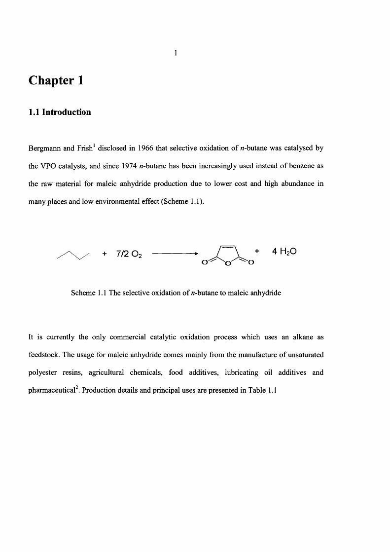
Bergmann and Frish1 disclosed in 1966 that selective oxidation o f «-butane was catalysed by
the VPO catalysts, and since 1974 «-butane has been increasingly used instead o f benzene as
the raw material for maleic anhydride production due to lower cost and high abundance in
many places and low environmental effect (Scheme 1.1).
+ 7/2 0 2 -► / \ + 4 H20
Scheme 1.1 The selective oxidation o f /?-butane to maleic anhydride
It is currently the only commercial catalytic oxidation process which uses an alkane as
feedstock. The usage for maleic anhydride comes mainly from the manufacture o f unsaturated
polyester resins, agricultural chemicals, food additives, lubricating oil additives and
pharmaceutical . Production details and principal uses are presented in Table 1.1
2
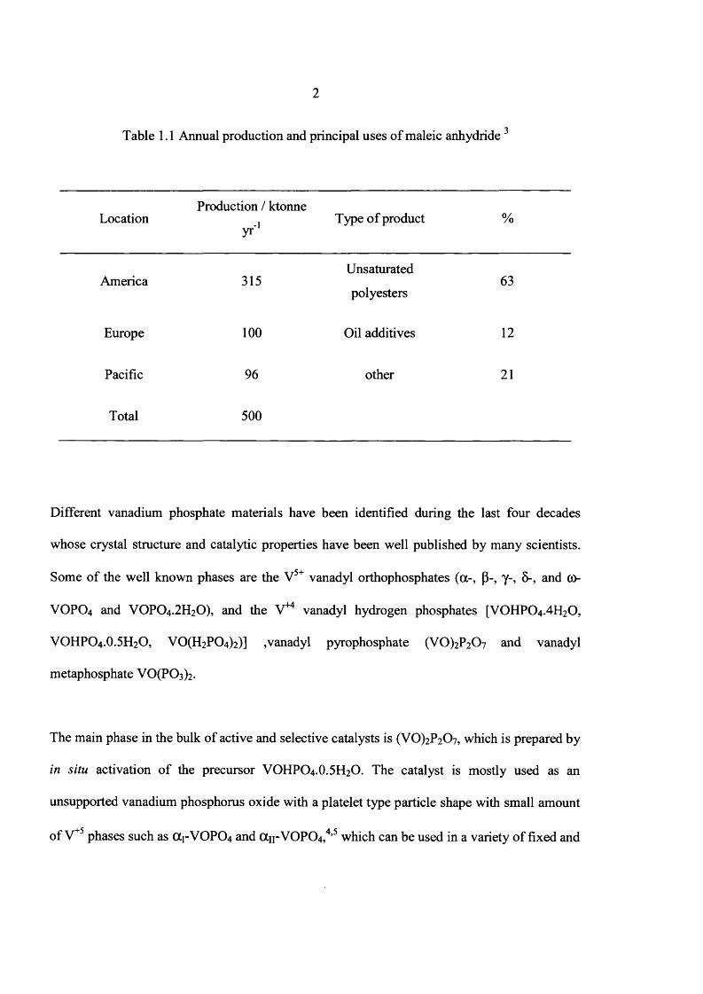
-jTable 1.1 Annual production and principal uses o f maleic anhydride
LocationProduction / ktonne
yrType o f product %
America 315Unsaturated
polyesters63
Europe 1 0 0 Oil additives 1 2
Pacific 96 other 2 1
Total 500
Different vanadium phosphate materials have been identified during the last four decades
whose crystal structure and catalytic properties have been well published by many scientists.
Some o f the well known phases are the V5+ vanadyl orthophosphates (a-, p-, y-, 5-, and co-
VOPO4 and VOPO4 .2 H2O), and the V+4 vanadyl hydrogen phosphates [VOHPO4 .4 H2O,
VOHPO4 .O.5 H2O, V 0(H 2P 0 4)2)] ,vanadyl pyrophosphate (VO)2P207 and vanadyl
metaphosphate V0 (P0 3 )2.
The main phase in the bulk o f active and selective catalysts is (V0)2P207, which is prepared by
in situ activation o f the precursor VOHPO4 .O.5 H2O. The catalyst is mostly used as an
unsupported vanadium phosphorus oxide with a platelet type particle shape with small amount
ofV *5 phases such as OC1-VOPO4 and (Xu-VOPC^,4,5 which can be used in a variety o f fixed and

3
mobile bed reactors. The reaction network involves the formation o f butene, 1,3-butadiene and
furan as intermediates. The active site for n- butane oxidation to maleic anhydride has been
f\ 8proposed as being the (200) plane o f vanadyl pyrophosphate ‘ and the yield o f maleic
o
anhydride improves when the active site o f the (200) plane o f (VO^PiCb is maximized.
For these reasons, the preparation o f highly selective catalysts has been the focus o f most VPO
studies. Many properties o f the final catalyst, such as crystalline behaviour and particle size,
are established when precursor forms.9 Hence, the preparation methods and reaction conditions
during the preparation affect the morphology o f VOHPO4 .O.5 H2O and ultimately the catalyst
performance.10 Therefore, careful preparation o f the precursor VOHPO4 .O.5 H2O is the key to
obtaining an effective catalyst.11
1.2 Proposed Active Sites and Mechanisms of n-Butane Oxidation
To date, many researchers have developed different models for /2-butane oxidation on the VPO
catalyst, which are based on the hypothetical sites present on the surface (200) plane12.
Bronsted acid sites (-POH group), Lewis acid sites (VIY and Vv), bridging oxygen (V-O-V, V-
O-P or VO(P)V) and terminal oxygen (Vv= 0 , VIY= 0) are proposed active sites on the surface
(200) plane.
13Pepera et al. reported that every two surface vanadium atoms are capable o f activating one
molecule o f oxygen, while the bulk o f the catalyst did not participate in /2-butane oxidation.

4
^-Butane does not reversibly chemisorb onto the surface while maleic anhydride does.
Although Pepera et a l did not report the mechanism o f oxidation, but they proposed that VIY
on the surface o f (VO)2P2 0 7 may assist homolytic cleavage o f the methylene C-H bond o f n-
butane. It is shown in Eq. 1.1
V lv + 2RH ------------ ► 2R + VnI + 2H20 Eq. 1.1
Centi et al. have calculated the rate constant for the theoretical dehydrogenation o f light
alkanes on a (VO)2P2C>7 catalyst with removal o f two hydrogen atoms. They showed that the
rate-determining step is the contemporaneous removal o f two methylene hydrogen atoms from
the carbon in the 2- and 3- positions in «-butane.
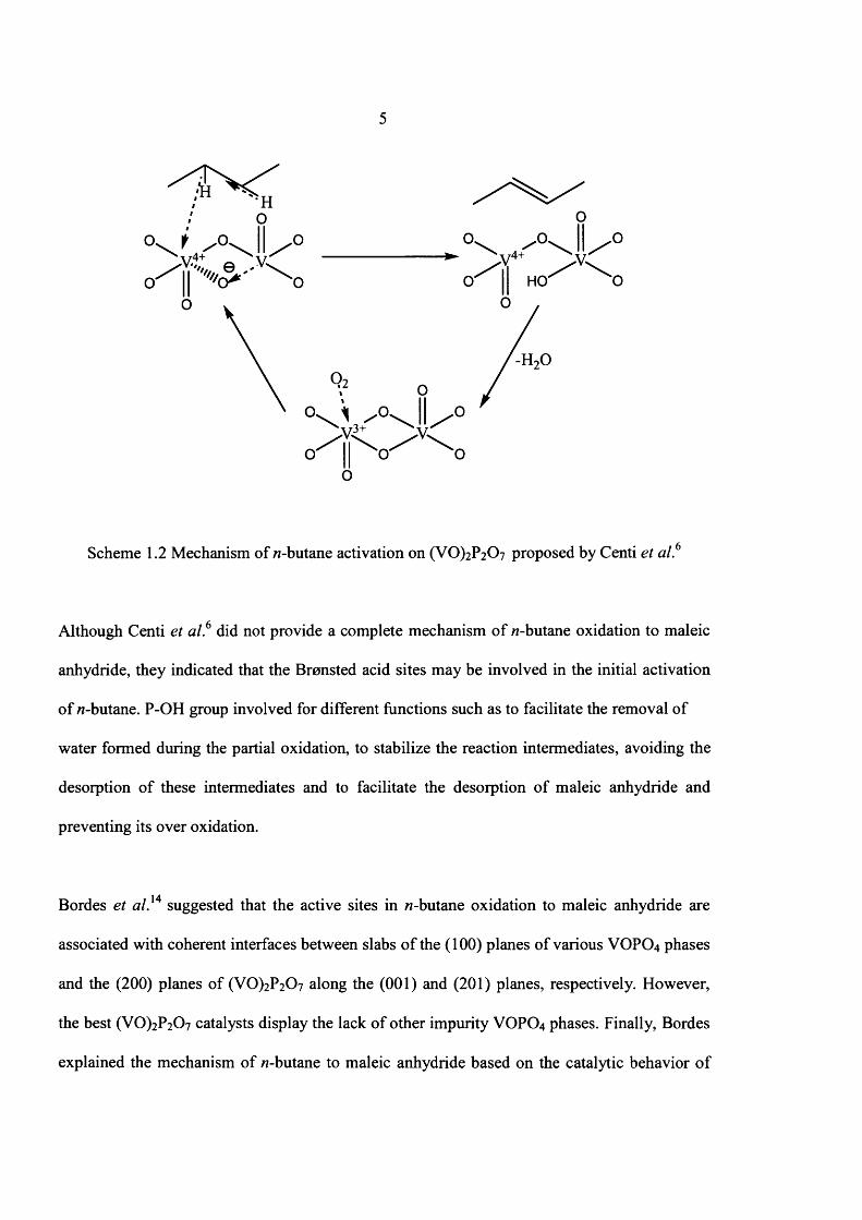
Centi et al.6 also proposed that the Lewis acid site and the bridging oxygen abstract two
hydrogen atoms from the two methylene groups o f «-butane via a concerted mechanism shown
in Scheme 1.2
5
Scheme 1.2 Mechanism of 77-butane activation on (VO)2 P2 0 7 proposed by Centi et a l 6
Although Centi et a l 6 did not provide a complete mechanism o f 77-butane oxidation to maleic
anhydride, they indicated that the Bronsted acid sites may be involved in the initial activation
o f 77-butane. P-OH group involved for different functions such as to facilitate the removal of
water formed during the partial oxidation, to stabilize the reaction intermediates, avoiding the
desorption o f these intermediates and to facilitate the desorption o f maleic anhydride and
preventing its over oxidation.
Bordes et al ,14 suggested that the active sites in 77-butane oxidation to maleic anhydride are
associated with coherent interfaces between slabs o f the (100) planes o f various VOPO4 phases
and the (200) planes o f (V 0 )2 P2 0 7 along the (001) and (201) planes, respectively. However,
the best (VO)2 P2 C>7 catalysts display the lack o f other impurity VOPO4 phases. Finally, Bordes
explained the mechanism o f 77-butane to maleic anhydride based on the catalytic behavior o f

6
non-equilibrated or over-oxidised VPO catalyst that contains different microcrystalline VOPO4
phases.
Volta and co-workers,15 on the contrary, believed that the active sites are not associated with
interfaces between these crystalline phases. On the basis o f comparison between XRD and
radical electron distribution data they suggested that the active phase for selective oxidation of
«-butane consists o f a mixture o f well- crystallized (VO)2P2 0 7 and an amorphous VOPO4
phase. This amorphous phase was identified as a precursor o f P-VOPO4, which formed at
higher reaction temperatures. After four years, Volta et a l.15 suggested on the basis o f kinetic
data as well as XRD and 31P MAS NMR results that domains o f y- VOPO4 supported on a
(VO^P2O7 mixture are necessary for selective «-butane oxidation. It is a better mechanism
because it was based on the experimental data when compared with other theoretical
mechanisms. Hutchings et al.16 and Volta and co-workers.17 suggested that the actives sites for
«-butane oxidation to maleic anhydride comprise a V+4AA+5 couple, well dispersed on the
surface o f a range o f VPO phases.
IQSchiott and Jorgennson applied the frontier orbital theory with Huckel calculation to explain
the formation o f 2,5-dihydrofuran from the butadiene intermediates and its vanadyl dimer
present in the (200) plane o f (VO)2P2 0 7 . Their calculations showed that V4+ = O is involved in
the (2 + 4) like cyclo addition o f butadiene, which then rearranges to 2, 5- dihydrofuran.
Molecular oxygen absorbed on the adjacent vanadium atom in the dimmer then activates the C-
H bond in the 2-position o f 2,5-dihydrofuran, leading to a hydrogen atom transfer to the
peroxospecies to give a surface-bound hydroperoxide group. The O- H group in O- O - H then
7
transfers to the neighboring 2,5-dihydrofuran derivative yielding the 2- hydroxyl derivative.
The asymmetric lactone (y-butyrolactone) may be obtained by the hydrogen atom transfer to
the adjacent radical oxovanadium site. The oxidation o f the 5- position o f y-butyrolactone to
maleic anhydride may take place in a similar fashion following the desorption o f water and
activation o f another molecule o f oxygen on the adjacent reduced vanadium site. There is no
experimental evidence for this mechanism.
Guliants et al.19 showed that the cis-dimeric site shown in Scheme 1.3, rather than the trans-
oxovanadium (IV) dimer, may be involved in the C-H bond cleavage in n-butane and other C4
molecules to maleic anhydride based on such dimeric peroxo site and Viv-Vv redox couple.
Some o f the important observations made during oxidation o f the probe molecules and
proposed mechanism were explained based on the dimeric site. Further, the oxidation of a
branched C4 alkane, isobutane, was carried out to probe the mechanism o f the C-H bond
activation o f alkanes on the VPO catalysts. Maleic anhydride was among the products o f
oxidation o f this branched alkane. In the case o f isobutane, the surface- bound peroxo radical
would show discrimination in activating first the weaker tertiary C-H bond. The hydroxylation
of the /-butyl radical would lead to /-butanol, it was an unselective path for maleic anhydride.
On the other hand, he explained the selective path for maleic anhydride which involved the
abstraction o f the two hydrogen atoms in positions 1 and 3. Activation o f the two methyl C-H
bond may occur resulting in the formation o f 1,3-diradical. Simple radical undergo skeletal
rearrangement, leading to linear 1,2-diradical and butene. Finally formation o f maleic
anhydride during isobutane oxidation on the VPO catalyst suggests that such skeletal
rearrangement does occur. On the other hand, it also indicates that the activation o f w-butane on
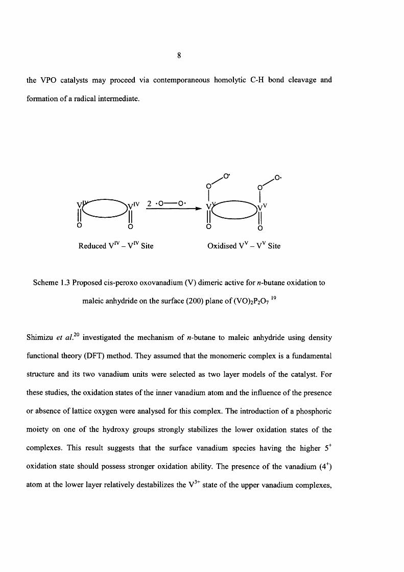
the VPO catalysts may proceed via contemporaneous homolytic C-H bond cleavage and
formation o f a radical intermediate.
'O* ^o*O' o '
V r > / IV 2 -O O-. o r
O O o {J
Reduced V " - V lv Site Oxidised Vv - Vv Site
Scheme 1.3 Proposed cis-peroxo oxovanadium (V) dimeric active for w-butane oxidation to
maleic anhydride on the surface (200) plane o f (VO)2P2 0 7 19
Shimizu et al. investigated the mechanism of «-butane to maleic anhydride using density
functional theory (DFT) method. They assumed that the monomeric complex is a fundamental
structure and its two vanadium units were selected as two layer models o f the catalyst. For
these studies, the oxidation states o f the inner vanadium atom and the influence o f the presence
or absence o f lattice oxygen were analysed for this complex. The introduction o f a phosphoric
moiety on one o f the hydroxy groups strongly stabilizes the lower oxidation states o f the
complexes. This result suggests that the surface vanadium species having the higher 5+
oxidation state should possess stronger oxidation ability. The presence o f the vanadium (4+)
atom at the lower layer relatively destabilizes the V3+ state o f the upper vanadium complexes,

9
and stabilizes the peroxo-vanadium (4+) complexes, which suggests that the lattice oxo-oxygen
in vanadyl pyrophosphate may be involved in the activation o f molecular oxygen. There is no
experimental data used for analyzing this mechanism.
1.3 Influence of P: V ratio on catalyst performance
The commercial catalysts are prepared with a slight excess o f phosphorus, typically with P: V
close to 1.1:l .8 Many studies reported that part o f the phosphorus sublimes during normal
operation and there are several reports that describe methods o f replenishing the catalyst with
21phosphorus without significantly interfering with plant operation. It is clear from a large
number o f studies that phosphorus in excess o f the 1:1 stoichiometric ratio is important for the
production o f selective VPO catalysts prepared in aqueous media. Selectivity to maleic
22anhydride improves as the P:V ratio increases for catalysts prepared in aqueous media, and
this has been related to the role o f excess phosphorous in these catalysts in stabilizing the 4+
oxidation state o f vanadium.
There is no clear evidence in the literature that catalysts prepared in organic media require a
P:V ratio greatly in excess o f the stoichiometric for optimum performance. Centi et a l 6
reported that yield-conversion plots for a number o f VPO catalysts with different P:V ratios
prepared in organic media. Clearly catalysts with P:V ratios less than 1:1 do not perform well,
especially at high conversions, but neither is optimum performance achieved with catalysts
with P: V ratios in excess o f 1:1.

10
1.4 Preparation of vanadium phosphorus oxide (VPO) catalyst precursors
VOHPO4 .O.5 H2O is the most important catalyst precursor for «-butane oxidation to maleic
anhydride because thermal treatment o f this VOHPO4 .O.5 H2O precursor transforms it into
vanadyl pyrophosphate catalyst which is highly active and selective for «-butane oxidation.
Therefore, preparation o f the catalyst precursor is a key factor in this research.
The structure o f the precursor and catalyst were not discovered until 1980s, and then the
precursor was called phase A, whereas the catalyst was referred as phase B. Now, the
structure o f both is well documented. To date, many material scientists have reported different
preparation methods for making catalyst precursors with or without mechanism o f crystal
growth. Commonly, three major preparation methods are used to make VOHPO4 .O.5 H2O
precursor and these are called VP A, VPO and VPD.23,8
Acid is used as the reducing agent in VPA method. In this method, V2O5 is refluxed with HC1,
(Eq. 1.2) and then H3PO4 is added to this mixture (Eq. 1.3). Finally, the resulting solution is
refluxed and filtered. This material has plate shaped morphology and its surface area was
2 103m /g. However, the obtained solid has more VO(H2P0 4 ) 2 impurity as compared with other
precursors obtained from VPO and VPD. Some vanadium phosphate phases and their unit cells
are listed in Table 1.2.
V20 5 + 6HC1 2V0C12 + 3H20 + Cl2 (Eq. 1.2)
VOCI2 + H3PO4 + 0.5H2O VOHPO4 .0.5H2O + 2HC1 (Eq. 1.3)

11
Table 1.2 Vanadium phosphate phases and their unit cells14
Phase Unit cell Cell parameters/nm
V 0(P 03)2 Tetragonal a= 1.096, c= 0.425
VOHPO4.0.5H2O Orthorhombica= 0.742, b= 0.960,
c= 0.569
(V 0)2P20 7 Orthorhombica= 0.773, b= 1.658,
c= 0.957
V 0 P 0 4.2H20 Tetragonal a= 0.620, c= 0.741
p- v o p o 4 Orthorhombica= 0.777, b= 0.614,
c= 0.697
a r V 0 P 0 4 Tetragonal a= 0.620, c= 0.411
ciii" v o p o 4 Tetragonal a= 0.601, c= 0.443
6- V 0 P 0 4 Orthorhombica= 0.642, b= 0.626,
c= 0.909
y- V 0 P 0 4 Monoclinica= 0.964, b= 1.533,
c= 1.662 and p= 93.04°
V 0(H 2P 04)2 Tetragonal a= 0.895, c= 0.797

12
The VPO and VPD preparation methods are carried out in organic solvent In the VPO route,
V2O5, phosphoric acid are refluxed (Eq.1.4), with an alcohol as solvent and reducing agent.
The recovered solid has a platelet morphology and its surface area was between 10-18 m /g.
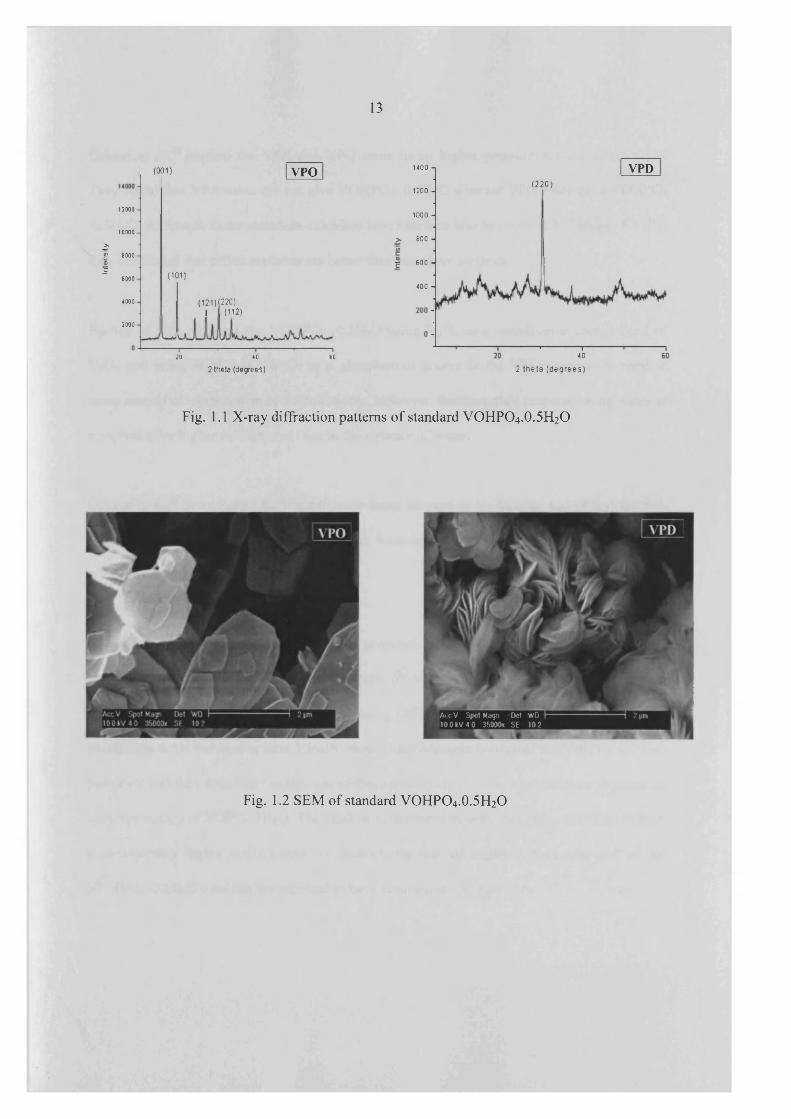
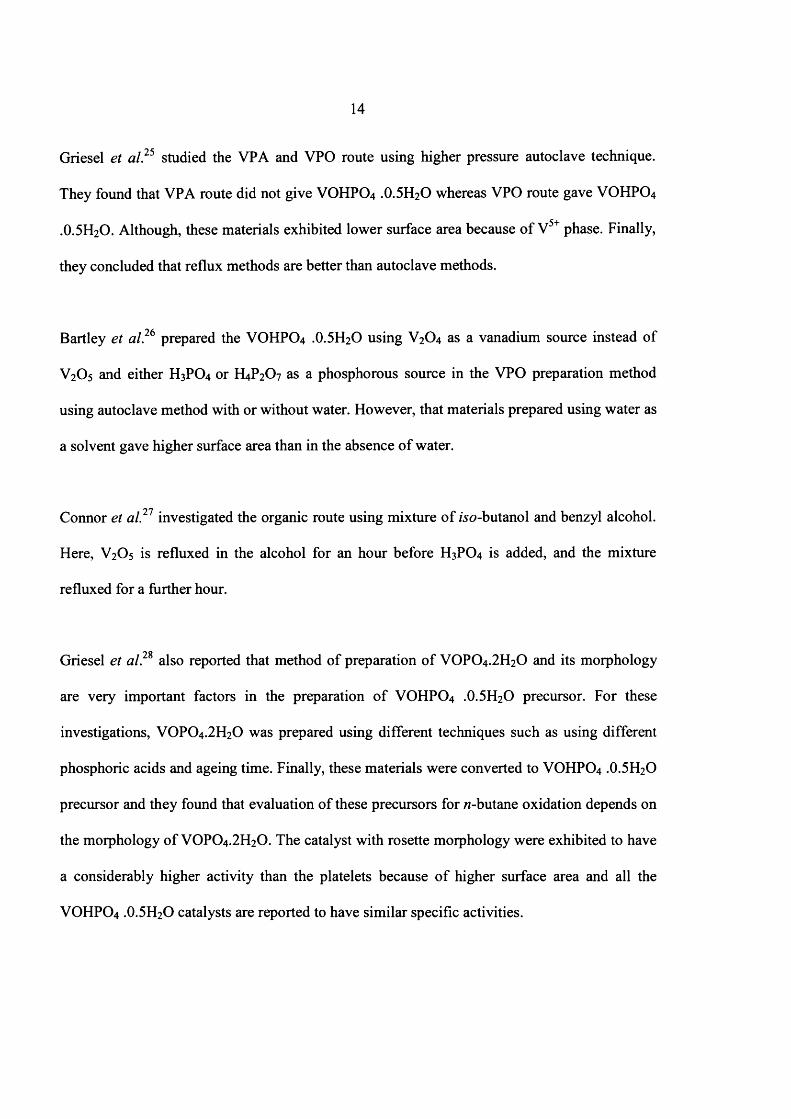
VOPO4 .2 H2O (Eq.1.5) is directly reduced by alcohols in VPD route (Eq.1.6). The morphology
o f these materials is varied depending on the alcohol used to reduce VOPO4 .2 H2O. Primary
alcohols give a rosette structure while secondary alcohols give platelet morphology. Rosette
structure materials exhibited higher surface area than other materials, which was 32 m2/g.24
XRD and SEM o f platelet and rosette structure materials are shown in Figure 1.1 and 1.2
respectively.
VPO
V20 5 + R-CH2-OH + 2 H3PO4 -> 2 VOHPO4 .0.5H2O + R-CH=0 + 2H20 (Eq. 1.4)
VPD
V20 5 + 2 H3PO4 + 2H20 2 V 0 P 0 4.2H20 (Eq. 1.5)
2 V 0 P 0 4.2H20 + R-CH2-OH -> 2 VOHPO4 .0.5H2O + R -C H O + 3H20 (Eq. 1.6)
Inte
nsit
y13
(001 ) VPO
12000
10000
8000
( 101)6000
( 121) (220)I (112)
4000
2000
20 402 theta (degrees)
60
1400
1200
1000
> 800w
I 600
400
VPD(2 2 0 )
' 1—40
2 theta (d egrees)
Fig. 1.1 X-ray diffraction patterns o f standard VOHPO4 .O.5 H2O
iAccV Spot Magn Del WD 100kV 40 35000x SE 10 2
Fig. 1.2 SEM o f standard VOHPO4.0.5H2O
14
Griesel et a l?5 studied the VPA and VPO route using higher pressure autoclave technique.
They found that VPA route did not give VOHPO4 .O.5 H2O whereas VPO route gave VOHPO4
.O.5 H2O. Although, these materials exhibited lower surface area because o f V5+ phase. Finally,
they concluded that reflux methods are better than autoclave methods.
Bartley et al.26 prepared the VOHPO4 .O.5H2O using V2O4 as a vanadium source instead of
V2O5 and either H3PO4 or H4P2O7 as a phosphorous source in the VPO preparation method
using autoclave method with or without water. However, that materials prepared using water as
a solvent gave higher surface area than in the absence o f water.
Connor et a l } 1 investigated the organic route using mixture o f iso-butanol and benzyl alcohol.
Here, V2O5 is refluxed in the alcohol for an hour before H3PO4 is added, and the mixture
refluxed for a further hour.
Griesel et al.2S also reported that method o f preparation o f VOPO4 .2 H2O and its morphology
are very important factors in the preparation o f VOHPO4 .O.5 H2O precursor. For these
investigations, VOPO4 .2 H2O was prepared using different techniques such as using different
phosphoric acids and ageing time. Finally, these materials were converted to VOHPO4 .O.5 H2O
precursor and they found that evaluation o f these precursors for /2-butane oxidation depends on
the morphology o f VOPO4 .2 H2O. The catalyst with rosette morphology were exhibited to have
a considerably higher activity than the platelets because o f higher surface area and all the
VOHPO4 .O.5 H2O catalysts are reported to have similar specific activities.
15
Mahony et a l} 9 investigated the crystallization o f VOHPO4 .O.5 H2O using VPO route. For this
study, initially, V2O5 and alcohol were refluxed then phosphoric acid was added. They found
that VOPO4 .2 H2O was rapidly formed. After 15 minutes, d-spacing shifted from 7.5 to 6.7 A ,
by this time, (001) phase o f VOHPO4 .O.5 H2O precursor forms at 5.7 A with a maximum
intensity at 60 minutes.
These observations lead to the first key point with respect to vanadium phosphate catalysts,
namely that the surface area is the factor that controls the activity o f catalysts prepared using
VOHPO4 .O.5 H2O as the precursor.
1.5 Preparation of other VPO phases for /i-butane oxidation
It is very important to understand how other phases can be synthesised or enhance their
formation in VOHPO4 .O.5 H2O preparation.
VOPO4 phases
(X1-VOPO4, CX11-VOPO4, Y-VOPO4, 6 -VOPO4 and P-VOPO4 can be prepared by calcination of
VOPO4 .2 H2O and VOHPO4 .O.5 H2O in air30. It has shown in scheme 1.4

16
VOHPO4.0.5H2O
400 to 650°C
5-VOPO,
740 to 780°C
V 0 P 0 42H20 (NH4)2[(V 0)2C20 4(HP04)].5H20
400 to 600°C 550°C
0Ci-VOPO4 P-V0 P04
750°C 600°C
780°Cy-V 0P 04 «___________________ a n-V 0 P 0 4 (NH4)2(V 0)2P 0 4
Scheme 1.4 preparation routes for VOP04 phases in static air environment30
Bordes et al.14,31 reported that VOP04 phases can be prepared via dehydration o f V 0 P 0 4.2H20
in air, which is shown in Eq. 1.7
400°C 720°C 750°CV0P04.2H20 --------> a r VOP04 > an-VOP04 > P-VOP04 Eq.1.7
VO(H2P 0 4) 2
V 0(H 2P 0 4)2 can be synthesized from reduction o f V 0 P 0 4.2H20 with 3-octanol.22 Bartley et
al.32,33 also reported that VO(H2P 0 4)2 can be synthesised by the reaction o f V2Os, H3P04 with
aldehyde or ketone.
17
V 0H P0 3.1.5H20
Guliants et a l,36 showed that VOHPO3.I.5H2O can be synthesized by the reaction o f V2O5,
alcohol (isopropyl or isobutyl) and H3PO3 using reflux stage method. Hutchings and co
workers34 prepared the vanadyl hydrogen phosphite, VOHPO3.I.5H2O hydrate by the reaction
of V2O5, H3PO4 and 1 -proponal in the absence o f water at 1 5 0 °C using autoclave method.
Whereas, VOHPO3.H2O can be obtained in the presence o f water.
Different vanadium phosphate phases can be synthesized using various experimental
techniques. Some o f these phases are active for butane oxidation.
1.6 Intercalation, exfoliation and reduction of V 0 P 0 4*2H20 with different
solvents
Intercalation o f organic molecules is widely used for modifying the chemical and physical
properties o f inorganic layered materials.35 The intercalation compounds o f layered vanadium
phosphate dihydrates (VOPO4 .2 H2O) are o f tremendous interest not only as fundamental
examples o f V-O-P nano-composites but also as intermediates for constructing novel V-P-O
‘Xfxnanostructures o f catalytic performance. Due to the weak interlayer binding in VOPO4 .2 H2O,
these materials can act as host to different guest molecules. Further, VOPO4 .2 H2O can be
intercalated by alcohols, aliphatic amines, acetone, pyridine, organometallic compounds,
glycols and amides. ’

18
Melanova et al. 39 reported that mixed intercalates can be prepared by reaction of
polycrystalline vanadyl phosphate dihydrate with liquid mixtures o f the primary alcohols in a
microwave field. They found the same mixed layer- type complexes can be obtained as
intermediary products o f exchange reactions consisting o f substitution o f one alcohol bound in
the solid intercalate by another alcohol introduced in the form of vapor.
Melanova et al.40 also reported that aliphatic aldehydes can not be used for the preparation of
intercalation compounds because the guests undergo aldol condensation and oxidation so these
intercalates are unstable. Benes et a l 41 investigated some intercalates o f vanadyl phosphate
with branched alcohols. They found that these alcohols were directly intercalated into vanadyl
phosphate dihydrate and formed intercalates compounds. However, in neither o f these studies
did report any data for /7-butane oxidation.
Yamamoto et a l 42 showed that VOPO4 2 H2O can be intercalated using acrylamide then it was
exfoliated by primary or secondary butanol and these compounds were reconstructed by
removal o f solvent. These materials consisted o f aggregated small flakes which were
morphologically very different from relatively large square platelets observed for both the
starting VOPO4 2 H2O and the initial intercalation compound.
Yamamoto et a l 43 reported that thin - layered sheets o f VOHPO4 O.5 H2O can be prepared
from V0PC>4'2H20 by intercalation, exfoliation and reduction in alcohol. Further, Kamiya et
al.44 reported that catalyst precursors (VOHPO4 O.5 H2O) can be prepared using exfoliation and
reduction o f V 0 P 0 4*2H20 in primary alcohol. VOHPO4 0.5H2O prepared with different

19
morphologies using exfoliation and reduction process is shown in Scheme 1 .5 . Furthermore, the
obtained (VO)2P2C>7 through the exfoliation - reduction was well crystallized and consisted of
thin flaky crystallites. Finally, Okuhara and co-workers44,45 found that (VO)2P2C>7 prepared
through the exfoliation - reduction was highly active and selective for oxidation o f w-butane.
V 0P04 2H20
20 pm
large platelets
delaminatedsheets
in alcohol
direct reduction
' ' - . with 2-BuOH ' \k
4 pm
platelets
reflux in 2-BuOH.
refluxJn 1-BuOH
fragments rose-petals
Scheme 1 . 5 VOHPO4 O.5H2O prepared using exfoliation and reduction process43
Benes et a l.46 analysed the intercalation o f VOPO42FI2O with branched alcohols. They found
that with increasing length o f the main chain the basal spacing o f the intercalates o f the C3, C4
and C5 isoalcohols changes linearly, increasing by one carbon atom ( 1 . 5 1 A) at a time.

20
Trchova et al.47 investigated the mechanism of intercalation for vanadium phosphate materials
using infrared and Raman spectroscopy techniques. They proposed the mechanism based on
these measurements that the vanadyl stretching band appears to be especially sensitive to atoms
coordinated to the vanadium within an octahedral arrangement in the host lattice structure,
during the intercalation its position at 1035 cm'1 in the anhydrous form changes to 995 cm'1,
typical for mono and dihydrates and they found that no formation o f vanadyl phosphate
monohydrate was observed during hydration of the anhydrous form under ambient conditions.
Benes et a l 4s explained the possible mechanisms o f intercalation reactions for vanadium
phosphates materials on the basis o f intercalation reactions of water and ethanol into anhydrous
vanadyl phosphate and redox intercalation of alkali metal cations into vanadyl phosphate
dihydrate. They found three possible mechanisms o f intercalation for vanadium phosphate
materials, which are based on (1) a concept of exfoliation o f layers (2) the formation o f stages
and randomly stacked layers (3) co-existence o f intercalated parts o f crystals of the host
separated by an advancing phase boundary. Further, it was reported that in the crystal o f the
cost, intercalated and non-intercalated parts o f the crystal coexist. A two phase system is
formed which is a transition area which has been designed as an advancing phase boundary.
The catalytic activity and selectivity of (V0)2P2 0 7 are greatly dependent on the microstructure
of the crystallites, control of the microstructure is critical for improvement o f the catalytic
performance. So, intercalation is the one of the key method for obtaining the different
crystallites.

21
1.7 Effect of promoters on n - butane oxidation over VPO catalysts
The activity o f vanadium phosphates is often enhanced by the addition o f low concentrations
o f metal cations known as promoters. For this reason, many industries have been using
promoted VPO catalysts for n-butane oxidation to maleic anhydride since last two decades.49
Bi, Co, U, Fe, Nb, Zn, Ce, La, Cu, Ti, Mo, Ca, Si, and Zr have been tried as promoters for the
preparation o f VOHPO4 .O.5 H2O precursors.50
Zazhigalov et al.51 modified the redox properties o f the VPO catalysts by incorporating
metallic Co in the catalyst precursors, which improved the desorption o f maleic anhydride and
increased the selectivity to maleic anhydride.
Comaglia et al. 5 2 ,53 analysed the effect o f Co cations on the activity and selectivity o f n-butane
oxidation to maleic anhydride over VPO catalysts prepared impregnation o f VOHPO4 .O.5 H2O
with cobalt acetate and acetyl acetonate. They found that Co added at 1-6 weight %
significantly improved the catalytic activity while slightly decreasing the maleic anhydride
selectivity. The best catalyst can be obtained using Co acetyl acetonate for impregnation o f the
VOHPO4 .O.5 H2O precursor. This catalyst exhibited an optimum concentration of very strong
Lewis acid sites, very low concentration o f isolated V(V) centers, and no V(V) phases.
Sajip et al.54 investigated the effect o f Co and Fe ions added during the VOHPO4 .O.5 H2O
precursor preparation using VPO route on «-butane oxidation to maleic anhydride. At low
levels, both Co and Fe significantly enhanced the intrinsic activity and selectivity to maleic

22
anhydride. They suggested that Co was insoluble in the (VO)2P2C>7 phase, which transformed
to a disordered V4+-V5+ phosphate phase during the activation of VOHPO4 .O.5 H2O. Whereas,
Fe may be soluble in the (VO)2P2 0 7 structure and, therefore, function as an electronic promoter
for this phase.
Shen et al.55 investigated Ce-Fe promoted VPO catalysts for zz-butane oxidation to maleic
anhydride in the absence o f gas-phase oxygen. They found that promoted catalysts exhibited
higher conversion and selectivity to maleic anhydride than the conventional catalyst. Finally,
they defined that the introduction o f Ce-Fe complex oxides improved the redox performance of
VPO catalysts by increasing the lattice oxygen activity.
Hutchings and co-workers56 analysed the zz-butane oxidation to maleic anhydride over
vanadium phosphate catalysts using group 13 elements as promoters. For this investigation,
two different types o f VOHPO4 .O.5 H2O were used, one is platelet morphology, and other one
is rosette structure. They also showed that these promoters can be switched from platelet-like
to rosette morphology. Although, all o f these promoters functioned as modifiers o f the VPO
crystal morphology, the In and Ga-promoted materials exhibited improved catalyst
performance in zz-butane oxidation to maleic anhydride.
VPO catalysts promoted with a mixture o f Mo, Zr and Zn ions were investigated by Xu et al.51
The combination o f these three cations created a synergistic effect that increased the
performance o f the promoted VPO catalysts. They found that these promoted VPO catalysts
exhibited high selectivity and conversion for zz-butane oxidation to maleic anhydride. However,

23
they did not report any comparison between promoted and un-promoted VPO catalysts for their
investigations. Xu et a l suggested that these three cations were incorporated in the vacant
surface sites as well as the bulk VPO structure.
Bismuth is the one o f the important promoters for H-butane oxidation. These promoted VPO
catalyst increased the selectivity to maleic anhydride in «-butane oxidation.58,59 Recently,
promoted VPO catalyst prepared using Pt and La-Bi as the promoters.60,61 Pt was incorporated
as H2PtCl6 into the layered VOHPO4 .O.5 H2O precursor during its synthesis using VPO route.
However, Pt-VPO catalysts did not apply for H-butane oxidation to maleic anhydride, but
catalytic performance o f these promoted catalysts was reported only for the hydrogenation o f
nitrobenzene and the oxidation o f tetrahydrofuran.
1.8 Crystal structures of vanadium phosphate phases
V 0 P 0 4.2H20
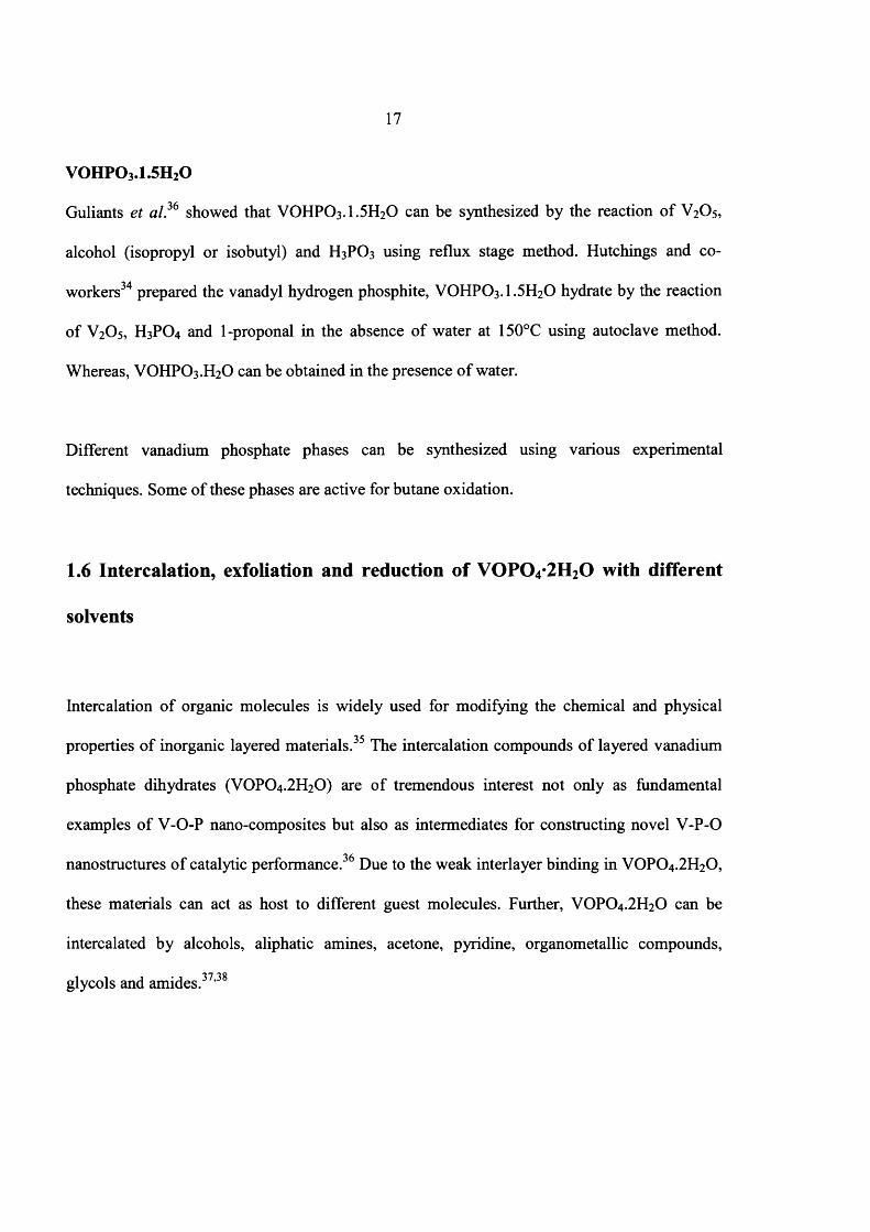
VOPO4 .2 H2O consists of layered VO6 octahedra o f which the equatorial oxygen atoms are
linked to PO4 groups. Above and below the equatorial plane is a short V = 0 and long V -0 bond
respectively, forming chains o f VC>6 octahedra. A specific layer consists o f two sheets, an
upper and lower floor. In VOPO4 .2 H2O the V =0 bonds in the same floor are cis orientated
towards each other, and trans oriented towards the V = 0 bonds in the other floor within the
same layer. Two water molecules are coordinated to vanadium in trans position to V = 0 and the
remaining two are isolated in the channels formed by the hydrogen bonding network1. It is
shown in Figure 1.3
24
Fig 1.3 Schematic representation o f layered VOPO4 .2 H2O structure14
Water molecules remove from the between the layers to form VOPO4 phases. ® = H2O
molecules, o = oxygen atoms
VOPO4 phases
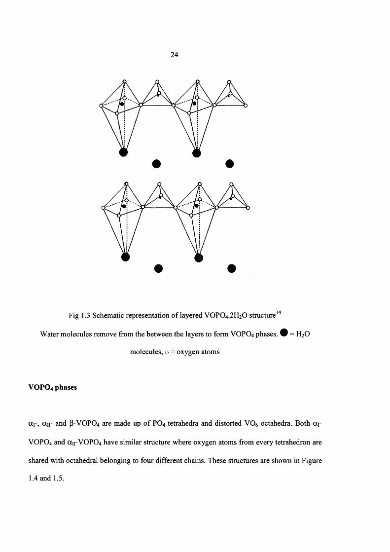
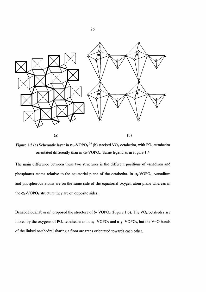
ocr, an- and P-VOPO4 are made up o f PO4 tetrahedra and distorted VC>6 octahedra. Both a r
VOPO4 and an-VOP0 4 have similar structure where oxygen atoms from every tetrahedron are
shared with octahedral belonging to four different chains. These structures are shown in Figure
1.4 and 1.5.
25
(a) (b)
171 P 0 4 tetrahedra
V06 octahedran with V=0 facing upwards
V06 octahedran with V=0 facing downwards
Fig 1.4 (a) A layer in the OC1-VOPO4 structure. Dashed lines represent the short vanadyl bond
facing downwards. Bold lines represent the upper layer30 (b) Stacked octahedral in (X1-VOPO4
linked with PO4 tetrahedra. Open circles represent oxygen atoms.
26
\ / A
7!\ / A
\ / A
(a) (b)
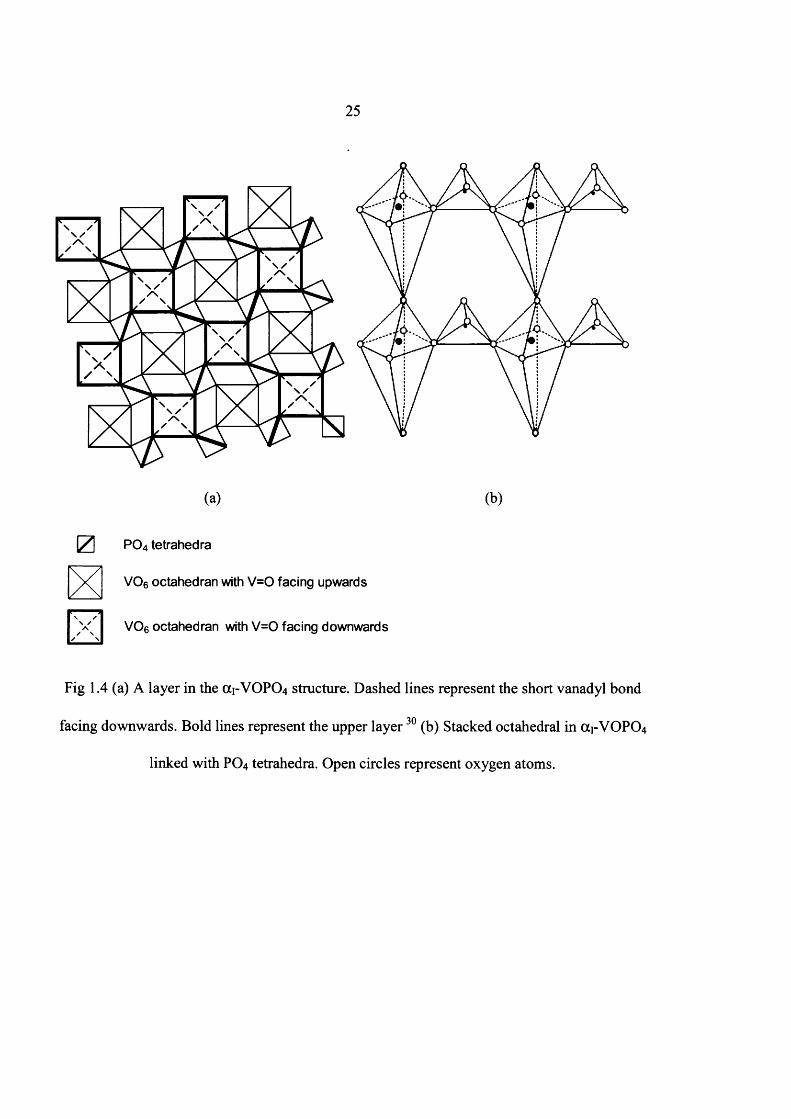
Figure 1.5 (a) Schematic layer in an-VOPCU 30 (b) stacked VC>6 octahedra, with PO4 tetrahedra
orientated differently than in OC1-VOPO4 . Same legend as in Figure 1.4
The main difference between these two structures is the different positions o f vanadium and
phosphorus atoms relative to the equatorial plane of the octahedra. In OC1-VOPO4, vanadium
and phosphorous atoms are on the same side o f the equatorial oxygen atom plane whereas in
the CX11-VOPO4 structure they are on opposite sides.
Benabdelouahab et al. proposed the structure o f 8 - VOPO4 (Figure 1.6). The VC>6 octahedra are
linked by the oxygens of PO4 tetrahedra as in a r VOPO4 and an- VOPO4, but the V=0 bonds
of the linked octahedral sharing a floor are trans orientated towards each other.
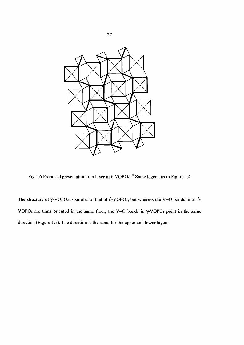
27
Fig 1.6 Proposed presentation o f a layer in 8-VOPO4.30 Same legend as in Figure 1.4
The structure o f Y-VOPO4 is similar to that of &-VOPO4, but whereas the V=0 bonds in o f 5-
VOPO4 are trans oriented in the same floor, the V=0 bonds in Y-VOPO4 point in the same
direction (Figure 1.7). The direction is the same for the upper and lower layers.

28
Fig L ? p roPoscdPreSem̂ n o f alayer
- « v UFO^ 3 0 o
e legendI ,

29
1.9 Transformation of VOHPO4.O.5 H2O precursor to (VO^PiOv
(VO)2P2C>7 is obtained when vanadium phosphate hemihydrate,VOHPO4.0.5H2O precursor is
heated to about 400°C in 1.5% butane/air. The trapped solvent molecules are removed, when
VOHPO4 .O.5 H2O precursor is heated, which makes structural defects, microcracks and
increase the surface area, here the precursor first transforms into an amorphous phase, then
dehydrates to crystalline (VO)2P2 0 7 and partially oxidized to V+5 orthophosphates when the
reactant mixture is introduced.62 The transformation o f VOHPO4 .O.5 H2O to (V0 )2P2 0 7 is
topotactic.23 Hence, morphology of the final catalyst depends on the morphology o f the
precursor.
Different crystalline final catalysts were obtained during the transformation of
VOHPO4 .O.5 H2O to (VO)2P2 0 7 depending on the morphology of the precursor, the presence of
defects in the structure, the activation temperature and time and the P/V ratio in the precursor.
This transformation has been investigated widely.
Hutchings and co-workers63 studied the transformation o f the VOHPO4.O.5 H2O into
(V0 )2P2 0 7 by in situ laser Raman spectroscopy and showed the morphology o f the final
catalyst remains unchanged. For these studies, three different VOHPO4 .O.5 H2O precursors
were converted to (VO)2P2 0 7 under the same reaction conditions. The three final catalysts gave
different Raman spectrum due to the P-O-P stretching. They also reported that the reactivity of
all these catalysts with oxygen was different because the variation in reactivity could be related
30
to differences in the nature o f the anion defects associated with the PO4 units in these materials
which would be reflected in the differences o f the P-O-P stretching region o f the spectrum.
Guliants et al.64 also investigated the transformation o f the VOHPO4 .O.5 H2O into (VO)2P2 0 7
by in situ laser Raman spectroscopy and X-ray diffraction techniques. They found that the
VOHPO4 .O.5 H2O is firstly transformed into disordered nanocrystalline (VO)2P2 0 7 with Y +5
phase , then it was converted to well-crystallised (VO)2P2C>7 in the equilibrated catalysts.
Finally, they concluded that the (200) planes o f (V0 )2P2 0 7 is a key factor for high activity and
selectivity for «-butane oxidation.
Torardi et al.65 studied the transformation o f the VOHPO4 .O.5 H2O into y-(VO)2P2 0 7 using
electron microscopy and X-ray diffraction. For these investigations, single crystal and powder
form o f the vanadyl hydrogen phosphate precursors were converted to pseudomorphs. They
found that size and shape of the catalyst are unchanged with respect to the starting materials.
Mahony et al.66 reported the morphology changes o f the VOHPO4 .O.5 H2O to (VO)2P207
during the two type o f transformations. They showed that first way is heated with air and
second one is heated with butane diluted with air. In the case o f air, firstly, amorphous solid
formed when precursor is heated at above 270°C whereas, crystalline V+5 formed when
VOHPO4 .O.5 H2O is heated at above 350°C. They also showed that second way is completely
different results from the first one, where crystalline (VO)2P2 0 7 was obtained without any
intermediate amorphous phase.
31
Sajip et al.61 analysed the structural transformation o f a cobalt-doped vanadium phosphate
hemihydrate to final catalyst using characterisation techniques. They prepared the cobalt-doped
catalyst precursor via organic route and it has a rhomboidal plate-like morphology. They also
applied the different activation times for the preparation of final catalyst. Finally, they found
that the morphology of the activated materials is unchanged with respect to original precursor.
Koyano et al.6* investigated the surface structure o f vanadyl pyrophosphate (VO)2P2 0 7 using
different characterisation techniques. They found that the Xi phase was obtained as a thin
surface layer on (VO)2P2C>7 when crystalline (VO)2P2 0 7 is reacted with oxygen molecule at
460°C. They also reported that (VO)2P2C>7 can be obtained when Xi phase (6 -VOPO4) is
reacted with «-butane. Based on these observations, they defined that the reversible redox
reactions between Xi phase and (VO)2P2C>7 occur by the reactions with butane and oxygen.
Ryumon et a l 69 investigated the transformation o f VOHPO4 .O.5 H2O to (V0 )2P2 0 7 using water
vapour. For these investigations, they used small and large crystallites with presence and
absence of water vapour. They found that a single- phase o f well crystallised (V0 )2P2 0 7 can be
obtained within a short reaction time under a reactant gas (0.9% «-butane, 10% O2) containing
40% water vapour using small crystallities. Whereas, the transformation took a longer period
(lOOh) without water vapour. In the large crystallites, (VO)2P2 0 7 was the main phase with
water vapour, whereas (X11-VOPO4 was obtained without water vapour. Therefore, water vapour
can accelerate the transformation o f VOHPO4.O.5 H2O to (VO)2P2 0 7 .

i
32
1.10 Conclusions
Selective oxidation o f «-butane to maleic anhydride is a commercial process which depends for
its operation on the structure o f active sites located on the basal plane o f (VO)2P2C>7. (200)
plane o f crystalline (VO)2P2 0 7 is considered as the most active and selective for /z-butane
oxidation. Different crystalline vanadium phosphorous oxide phases were obtained during the
transformation o f the VOHPO4 .O.5 H2O precursors to the final catalyst, (VO)2P2 0 7 depending
on
• the temperature, time and atmosphere o f activation
• the morphology o f the precursors
• P/V ratio in the precursors and
• the presence defects in the structure
Therefore, numbers o f new preparation routes have been concentrated for obtaining the good
materials. However, most o f these methods have focused on the preparation of
VOHPO4 .O.5 H2O with differing morphologies and surface area.
33
1.11 Aim of this work
The catalytic performance of the VPO catalysts depends on (i) the method o f VOHPO4 .O.5 H2O
preparation (ii) the procedures of activation and conditioning o f the precursor at high
temperature and (iii) the nature o f metal promoters.
The preparation o f VOHPO4.O.5 H2O depends on several factors such as types and
concentration o f reagents, reducing agents and solvents, the reduction temperature and
synthesis duration. Here, types o f alcohols (C4 and >Cg) and various reduction temperatures
were used for this investigation in VPD route.
Firstly, the addition of alkane in VPD method was studied. Different morphology materials
were obtained when different amount o f alkane solvent used and this led to a study into the
different factors that influence the morphology o f vanadium phosphate phase formed under
different conditions.
The second aim of this project was to synthesis new materials as catalysts for butane oxidation.
The first synthetic route studied was gas phase reduction o f VOPO4 .2 H2O. Traditionally the
reduction is carried out with either an aqueous reducing agent or an alcohol as the reducing
agent. In this study we investigated using gas phase reductions at higher temperatures.

34
1.12 References
(1) R. L. Bergmann and N. W. Frisch, US Patent 3293268, 1966, assigned to Princeton
Chemical Research
(2) Culbertson BM, Catal. Today, 1987, 1, 609
(3) Chemical week, 1997
(4) G. Centi, Catal Today, 1993, 16, 1
(5) V. V. Guliants, J. B. Benziger, S. Sundaresan, I. E. Wachs, J- M. Jehng, J. E. Roberts,
Catal. Today, 1996,28,275
(6) G. Centi, F. TrifirO, J. R. Ebner, V. M. Franchetti, Chem. Rev. 1988,88,55
(7) J. R. Ebner, M. R. Thompson, Catal. Today, 1993, 16, 51
(8) H. S. Horowitz, C. M. Blackstone, A. W. Sleight, G. Teufer, Appl. Catal, 1998, 38, 193
(9) E. Bordes, Catal. Today, 1993, 16, 27
(10) C. J. Kiely, A Burrows, S. Sajip, G. J. Hutchings, M. T. Sananes, A. Tuel and J. C.
Volta, J. Catal, 1996,162,31
(11) G. Centi, Catal. Today, 1993,16, 5
(12) F. Cavani, F. TrifirO, Catalysis, 1994, 11, 246
(13) M. A. Pepera, J. L. Callahan, M. J. Desmond, E. C. Milberger, P. R. Blum and N. J.
Bremer, J. Am. Chem. Soc, 1985, 107(17), 4883
(14) E. Bordes, Catal. Today, 1987, 1, 499
(15) G. Bergeret, M. David, J. P. Broyer, J. C. Volta, G. Hecquet, Catal. Today 1987, 1, 37
(16) G. J. Hutchings, C. J. Kiely, M. T. Sananes-Schulz, A. Burrows and J. C. Volta. Catal
Today, 1996, 28, 275
35
(17) M. T. Sananes-Schulz, A. Tuel, G. J. Hutchings, J. C. Volta. J. Catal, 1997, 166, 2,
388
(18) B. Schi0tt, K. A. J0rgensen, Catal. Today 1993,16, 79
(19) V. V. Guliants, S. A. Holmes, J. Mol. Catal, 2001, 175,1-2, 227
(20) R. Shimizu and T. Fuchikami, Catalysis Today, 2001, 71, 137
(21) B. K. Hodnett, Catal. Lett, 1985, 27, 373
(22) B. K. Hodnett, Ph. Permanne and B. Delmon, Appl. Catal, 1983, 6, 231
(23) J. W. Johnson, D. C. Johnston, A. J. Jacobson and J. F. Brody, J. Am. Chem. Soc, 1984,
106,8123
(24) I. J. Ellison, G. J. Hutchings, M. T. Sananes and J. C. Volta, J. Chem. Soc. Commun,
1994, 1093
(25) L. Griesel, J. K. Bartley, R. P.K. Wells and G. J. Hutchings, Catalysis Toady, 2005, 99,
131
(26) J. K. Bartley, J.A. Lopez-Sanchez and G. J. Hutchings, Catalysis Toady, 2003, 81, 197
(27) M. O. Conner, F. Dason and B. K. Hodnett, Appl. Catal., 1990, 64, 161
(28) L. Griesel, J. K. Bartley, R. P.K. Wells and G. J. Hutchings, Journal o f Molecular
Catalysis, 2004, 220, 113
(29) L. O’Mahony, D. Sutton and B. K. Hodnett, Catalysis Today, 2004, 91-92, 185
(30) F. Benabdelouahab, J. Claude Volta and R. Oliver, Journal o f Catalysis, 1994, 148, 334
(31) E. Bordes and P. Courtine, J. Catal, 1979, 57, 236
(32) J. K. Bartley, R. P. K. Wells and G. J. Hutchings, Journal o f Catalysis, 2000,195, 423
(33) J. K. Bartley, C. Rhodes, C. J. Kiely, A. F. Carley and G. J. Hutchings, Phys. Chem.
Chem. Phys., 2000, 2, 4999
36
(34) Wen-Sheng Dong, J. K. Bartley, Nian-Xue Song and G. J. Hutchings, Chem. Mater,
2005
(35) M.S. Whittingham, A. J. Jacobson, Intercalation Chemistry, Academic Press, New
York, 1982
(36) V. V. Guliants, J. B. Benziger, S. Sundaresan, Chem. Mater, 1995, 7, 1485
(37) S. Okuna, G. Matsubayashi, J. Chem. Soc. Dalton Trans. 1992, 2441
(38) P. Capkova, M. Trchova, V. Zima and H. Schenk, Journal o f Solid State Chemistry,
2 0 0 0 ,150, 356
(39) K. Melanova, L. Benes and V. Zima, Journal o f Inclusion and Macrocyclic Chemistry,
1999, 33, 391
(40) K. Melanova, L. Benes and V. Zima, Journal o f Solid State Chemistry, 2001, 157, 50
(41) L. Benes, V. Zima and K. Melanova, Eur. J. Inorg. Chem, 2001, 1883
(42) N. Yamamoto, T. Okuhara and T. Nakato, J. Mater. Chem., 2 0 0 1 ,11, 1858
(43) N. Yamamoto, N. Hiyoshi and T. Okuhara Chem. Mater., 2 0 0 2 ,14, 3882
(44) Y. Kamiya, S. Ueki, N. Hiyoshi, N. Yamamoto and T. Okuhara, Catalysis Today, 2003,
78, 281
(45) Y. Kamiya, N. Hiyoshi, N. Hiyoshi and T. Okuhara, Catalysis Today, 2003, 78, 281
(46) L. Benes, V. Zima and K. Melanova, Eur. J. Inorg. Chem, 2001, 1883
(47) M. Trchova, P. Capkova, P. Matejka, K. Melanova, L. Benes and E. Uhlirova, Journal
o f Solid State Chemistry, 1999,148, 197
(48) L. Benes, K. Melanova and V. Zima, Journal o f Inclusion Phenomena and Molecular
Recognition in Chemistry, 1998, 31, 275
(49) G. J. Hutchings, Appl. Catal, 1991, 72, 1
37
(50) G. J. Hutchings and R. Higgins, J. Catal, 1996, 162, 153
(51) V. A. Zazhigalov, J. Haber, J. Stoch, A. I. Pyatnitzkaya, G. A. Komashko, V.M.
Belousov, Appl. Catal. A 1993, 96, 135
(52) L. M. Comaglia, S. Irusta, E . A. Lombardo, M. C. Durupty, J. C. Volta Catal.Today.
2003, 78, 291
(53) L. M. Comaglia, C. R. Carrara, J. O. Petunchi, E . A. Lombardo, Catal. Today. 2000,
57,313
(54) S. Sajip, J. K. Bartley, A. Burrows, M. T. Sananes, A. Tuel, J. C. Volta, C. J. Kiely
and G. J. Hutchings, New J. Chem., 2001, 25, 125
(55) S. Shen, J. Zhou, F. Zhang, L. Zhou, R. Li, Catal. Today, 2002, 74, 37
(56) F. Javier Cabello Sanchez, J.A. Lopez-Sanchez, R P. K. Wells, Colin Rhodes, and G.
J. Hutchings, New. J. Chem., 2001, 25, 1528
(57) L. Xu, X. Chen, W. Ji, Q. Jan, Y. Chen, React. Kinetics. Catal. Lett., 2002, 76, 2, 335
(58) N. Yamazoe , H. Morishige, J. Tamaki, N. Miura, Stud. Surf. Sci. Catal. 1993, 75,1989
(59) P. Ruiz, Ph. Bastians, L. Caussin, R. Reuse, L. Dasa, D. Acosta, B. Delmon,Catal.
Today, 1993,16, 99
(60) A. Datta , M. Agarwal, S. Dasgupta, R. Y. Kelkar, J. Mol. Catal. A, 2003,198, 205
(61) B.Solsona, V. A. Zazhigalov, J. M. Lopez Nieto, I. V. Bacherikova, E. A. Diyuk, Appl.
Catal. A., 2003, 249, 81
(62) L. M. Comaglia, C. A. Sanchez, E . A. Lombardo, Appl. Catal. 1993, 95, 117
(63) F. Javier Cabello Sanchez, R P. K. Wells, Colin Rhodes, J. K. Bartley, C. J.Kiely and
G. J. Hutchings, Phys. Chem. Chem. Phys., 2001, 3, 4122
38
(64) V. V. Guliants, S. A. Holmes, J. B. Benziger, P. Heaney, D. Yates and I. E. Wachs, J.
Mol. Catal 2001, 172, 265
(65) C. C. Torardi, Z. G. Li and H. S. Horowitz, J. of. Solid State Chemistry, 1995, 119, 349
(66) L. O. Mahony, T. Curtin, J. Henry, D. Zemlyanov, M. Mihov and B. K. Hodnet,
Applied Catalysis A: General, 2005, 285, 36
(67) S. Sajip, J. K. Bartley, A. Burrows, C. Rhodes, J. C. Volta, C. J. Kiely and G. J.
Hutchings, Phys. Chem. Chem. Phys., 2001, 3, 2143
(68) G. Koyano, T. Okuhara and M. Misono, J. Am. Chem. Soc, 1998, 120, 767
(69) N. Ryumon, H. Imai, Y. Kamiya and T. Okuhara, Applied Catalysis A, 2006, 297, 73

39
Chapter 2
Experimental Details
2.1 V-P-O materials Preparation
Pure vanadium phosphate materials were prepared via new preparation routes. Firstly,
VOPO4 2 H2O was prepared using different vanadium sources and phosphoric acids based
on the standard preparation method and some o f these VOPO4 2 H2O were transformed to
final catalyst under the reducing environment (chapter 4).Secondly, different morphology
VPO materials were synthesised using alkane solvent via standard VPD route (chapter 3).
These materials were characterized by combination o f XRD, laser Raman spectroscopy,
SEM, TEM and BET surface area measurements. These characterized materials were
compared with previous results and materials were evaluated for the selective oxidation o f
«-butane to maleic anhydride.
40
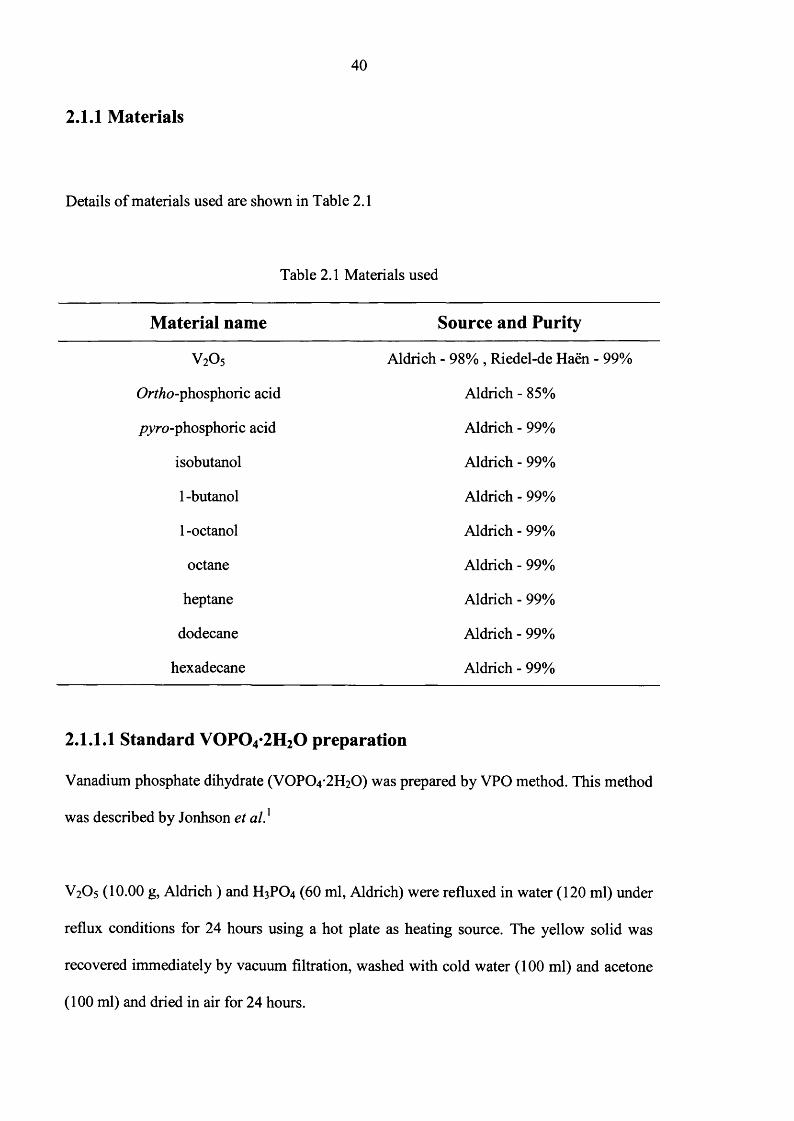
2.1.1 Materials
Details o f materials used are shown in Table 2.1
Table 2.1 Materials used
Material name Source and Purity
V 2O5 Aldrich - 98% , Riedel-de Haen - 99%
Ortho-phosphoric acid Aldrich - 85%
pyro-phosphoric acid Aldrich - 99%
isobutanol Aldrich - 99%
1 -butanol Aldrich - 99%
1 -octanol Aldrich - 99%
octane Aldrich - 99%
heptane Aldrich - 99%
dodecane Aldrich - 99%
hexadecane Aldrich - 99%
2.1.1.1 Standard V 0 P 0 4*2H20 preparation
Vanadium phosphate dihydrate (VOPO4 2 H2O) was prepared by VPO method. This method
was described by Jonhson et a l}
V2O5 (10.00 g, Aldrich) and H3PO4 (60 ml, Aldrich) were refluxed in water (120 ml) under
reflux conditions for 24 hours using a hot plate as heating source. The yellow solid was
recovered immediately by vacuum filtration, washed with cold water ( 1 0 0 ml) and acetone
(100 ml) and dried in air for 24 hours.

41
2.1.1.2 Using/jyw-phosphoric acid
This method was very similar to that described above except for the use o f pyre-phosphoric
acid instead o f ort/zo-phosphoric acid (chapter 4)
V2O5 (10.00 g, Aldrich or Riedel-de H aen) and H4P2O7 (40.00 g, Aldrich) were refluxed in
water (120 ml) under reflux conditions for 24 hours using a hot plate as heating source. The
yellow solids was recovered immediately by vacuum filtration, washed with cold water
(100 ml) and acetone (100 ml) and dried in air at 110°C for 24 hours.
2.1.1.3 Using organic solvent
V2O5 (5.90g, Aldrich) and isobutanol (125 ml, Aldrich) were heated at temperature between
55-60° C for 24 hours using a hot plate as heating source. Above mixture was cooled for 24
hours, then H3PO4 (4.88 ml, Aldrich) was added to the above mixture and refluxed for 24
hours. The yellow solids was recovered immediately by vacuum filtration, washed with
cold water (100 ml) and acetone (100 ml) and dried in air at 110°C for 24 hours.
2.1.2 Preparation of VOHPO4*0.5H2O
VPO (organic route)
V2O5 (2.00 g, Aldrich) and H3PO4 (1.66 ml, Aldrich) were refluxed with 1-butanol (50 ml,
Aldrich) for 24 hours. The recovered blue solid was then heated under reflux in water for 2
hours (90ml H2C)/g solid) to remove the impurity VO(H2PC>4)2. The suspension was then
filtered at hot, washed with acetone (50 ml) and dried in air at room temperature for 24
hours.
42
VPD (dihydrate route)
VPD is the reduction o f vanadium phosphate VOPO4 .2 H2O with alcohol as reducing agent
and solvent.
The VOPO4 2 H2O (1.00 g) was refluxed in isobutanol (25 ml, Aldrich) for 24 hours. The
pale blue solid was recovered by vacuum filtration and washed with alcohol (50 ml) and
acetone (50ml). The recovered solid was then heated under reflux in water for 2 hours
(90ml H2 0 /g solid) to remove the impurity VO(H2PC>4)2 . The suspension was then filtered
hot, washed with warm water (100 ml) and dried in air at 110°C, 24 hours.
2.1.3 New VPD preparation routes
The influence o f the alkane solvent was investigated in the VPD preparation method
(Chapter 3). Different variables were used for this investigation (V:alcohol mole ratio, total
volume, alcohol:alkane volume ratio (concentration o f alcohol) and different alcohol
structure).
2.1.3.1 Using different concentrations of 1-butanol and different total
volumes
VOPO4 2 H2O (l.OOg) was refluxed in 1-butanol (25 ml) and different quantities (10, 25, 50,
75 100, 150 and 400 ml) o f the alkane solvent (Heptane, octane, dodecane or hexadecane)
for 24 hours. The resulting material recovered by vacuum filtration and washed with
alcohol (50 ml) and acetone (50 ml) and dried in air at 110°C for 24 hours.

43
2.1.3.2 Using different concentrations of primary alcohol and same total
volume (175 ml)
VOPO4 2 H2O (l.OOg) was refluxed in different quantities o f the 1-butanol or 1 -octanol and
octane (0, 5, 15, 25, 50, 100, 125, 150, 160, 170 and 175 ml) total volume up to 175 ml for
24 hours. The resulting material was recovered by vacuum filtration and washed with
alcohol (50 ml) and acetone (50 ml) and dried in air at 110°C for 24 hours.
2.1.3.3 Using same V: OH ratio (1:50) and same total volume (175 ml)
VOPO4 2 H2O (V: alcohol = 1: 50) was refluxed in different quantities o f the 1-butanol or 1-
octanol and octane solvent (0, 5, 15, 25, 50, 100, 125, 150 and 160 ml) total volume up to
175 ml for 24 hours. The resulting material was recovered by vacuum filtration and washed
with alcohol (50 ml) and acetone (50 ml) and dried in air at 110°C for 24 hours.
2.1.4 Preparation of (VO)2P207 by using direct route
VOPO4 2 H2O was reduced to the final catalyst in the gas phase. Catalyst transformation
was carried out using the procedure outlined below. (Chapter 4)
Reaction conditions were
(1) different time (6 , 24, 72 hours)
(2) temperature (450°C to 550°C)
(3) different gas mixture (5% ItyAr, He and isobutanol)
VOPO4 2 H2O (0.70 g) was loaded into the reactor and the desired gas flow established
through the bypass using a bubble meter. The gas was passed over the VOPO4 2 H2O and

44
the temperature ramped at 3°C / min to the desired reaction temperature and VOPO4 2 H2O
for different times. Outline o f the reactor has shown in Figure 2.1
Thermocouple
5% H2/Ar
M ass Flow Controller
Tem peraturecontroller
Furnace
Stainless steel tubeMaterial
Waste gas
Fig. 2.1 Schematic o f the apparatus for the preparation o f final catalyst using new route
2.2 Catalyst Testing
Butane oxidation was performed over a fixed catalyst bed in a stainless steel microreactor
(1/4” inner diameter). Butane and air were mixed from separate cylinders in a ratio o f 1.5%
butane in air. The GHSV was maintained in the order o f 3000 h'1, and catalyst precursors
were activated for 72 hours at 400°C with 1.5% butane in air. The stationary values
(selectivity and conversion) were obtained after about 72 hours o f the reaction. Thus,
conversion and selectivity were determined from the data collected between 80 to 1 0 0
hours (average value was calculated).
45
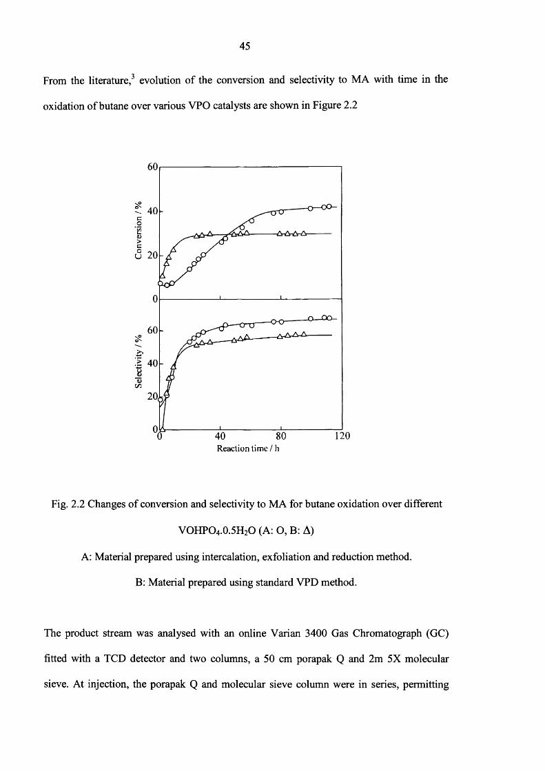
From the literature,3 evolution o f the conversion and selectivity to MA with time in the
oxidation o f butane over various VPO catalysts are shown in Figure 2.2
coKfil_<D>cc
_ 0 — O O -
>
<L>
120Reaction tim e/ h
Fig. 2.2 Changes o f conversion and selectivity to MA for butane oxidation over different
VOHPO4.0.5H2O (A: O, B: A)
A: Material prepared using intercalation, exfoliation and reduction method.
B: Material prepared using standard VPD method.
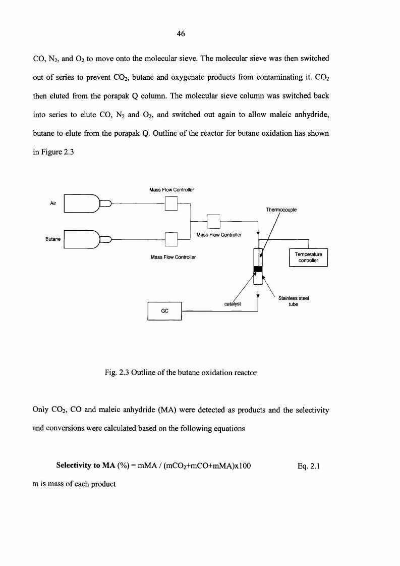
The product stream was analysed with an online Varian 3400 Gas Chromatograph (GC)
fitted with a TCD detector and two columns, a 50 cm porapak Q and 2m 5X molecular
sieve. At injection, the porapak Q and molecular sieve column were in series, permitting
46
CO, N 2, and O2 to move onto the molecular sieve. The molecular sieve was then switched
out o f series to prevent CO2 , butane and oxygenate products from contaminating it. CO2
then eluted from the porapak Q column. The molecular sieve column was switched back
into series to elute CO, N 2 and O2, and switched out again to allow maleic anhydride,
butane to elute from the porapak Q. Outline o f the reactor for butane oxidation has shown
in Figure 2.3
Mass Flow Controller
Thermocouple
Mass Flow Controller
Mass Flow Controller
Stainless steel tubecatalyst
GC
Temperaturecontroller
Fig. 2.3 Outline o f the butane oxidation reactor
Only CO2, CO and maleic anhydride (MA) were detected as products and the selectivity
and conversions were calculated based on the following equations
Selectivity to MA (%) = mMA / (mC02+mC0+mM A)x 100 Eq. 2.1
m is mass o f each product
47
Conversion (%) = mMA+mCO mC02 /m(MA+CO+C02+butane)xlOO Eq. 2.2
Specific activity (mol MAh^m'2) = butane flow (m olh1) x MA conversion (%) x MA
9 iselectivity (%) / mass catalyst (g) / surface area (m g ' ) Eq. 2.3
2.3 Experimental Techniques
2.3.1 Powder X-ray Diffraction (XRD)
Powder X-ray diffraction is a versatile and non-destructive analytical technique for
identification and quantitative determination o f the various crystalline forms, known as
phases o f compounds present in powdered and solid samples. Identification is achieved by
comparing the X-ray diffraction pattern or diffractogram obtained from an unknown sample
with an internationally recognised database containing reference patterns for more than
70,000 phases and reported in the literature. Modem computer-controlled diffractometer
systems use automatic routines to measure, record and interpret the unique diffractogram
produced by individual constituents in even highly complex mixture.
A crystal lattice is a regular three dimensional distribution (cubic, rhombic, etc) o f atoms in
space. These are arranged so that they form a series o f parallel planes separated from one
another by a distance d, which varies according to the nature o f the material. For any
crystals or phases exist in a number o f different orientations, each with its own specific d-
spacing.
48
Investigations o f the internal structure o f the crystal depend on a penetrating radiation that
will enter the material and will show interference effects as a result o f scattering from the
ordered array o f scattering centers. X-rays have the necessary penetrating power and show
interference effects since they have wavelengths o f the same order o f magnitude as the
spacing o f crystal planes.
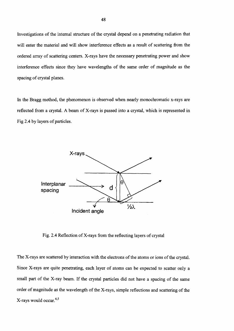
In the Bragg method, the phenomenon is observed when nearly monochromatic x-rays are
reflected from a crystal. A beam o f X-rays is passed into a crystal, which is represented in
Fig 2.4 by layers o f particles.
Interplanarspacing
X-rays
Incident angle
Fig. 2.4 Reflection o f X-rays from the reflecting layers o f crystal
The X-rays are scattered by interaction with the electrons o f the atoms or ions o f the crystal.
Since X-rays are quite penetrating, each layer o f atoms can be expected to scatter only a
small part o f the X-ray beam. If the crystal particles did not have a spacing o f the same
order o f magnitude as the wavelength o f the X-rays, simple reflections and scattering o f the
X-rays would occur.4,5
49
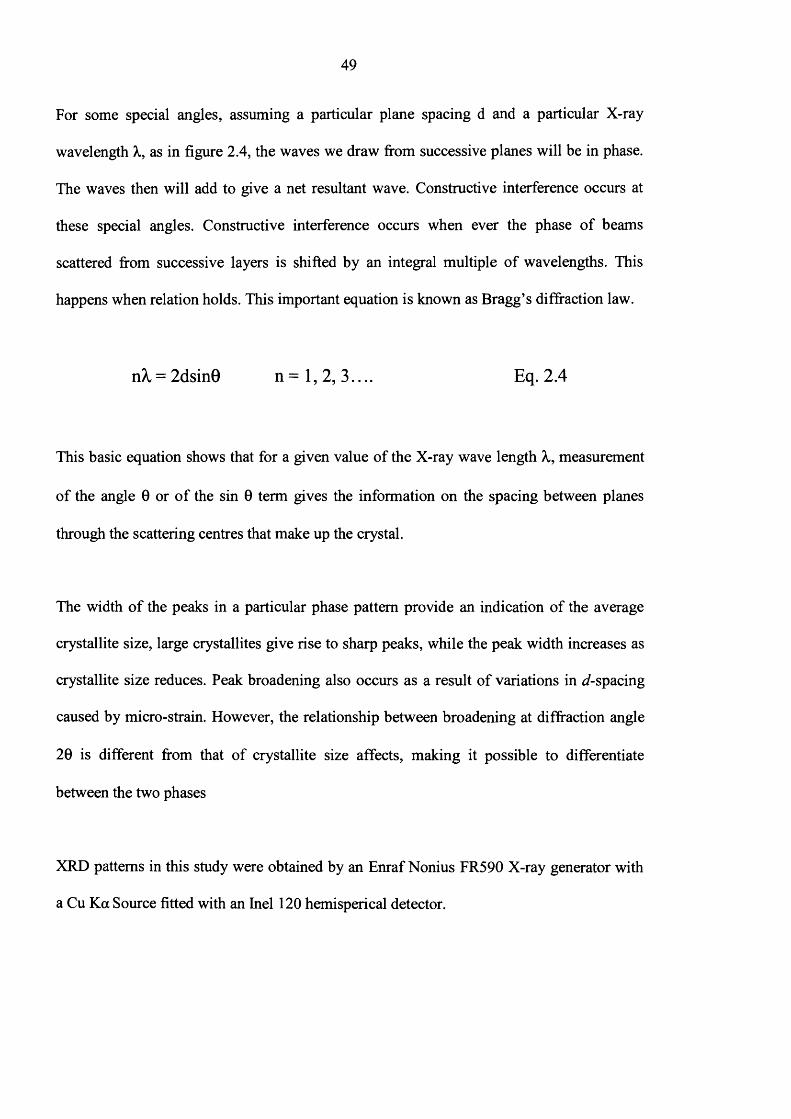
For some special angles, assuming a particular plane spacing d and a particular X-ray
wavelength X, as in figure 2.4, the waves we draw from successive planes will be in phase.
The waves then will add to give a net resultant wave. Constructive interference occurs at
these special angles. Constructive interference occurs when ever the phase o f beams
scattered from successive layers is shifted by an integral multiple o f wavelengths. This
happens when relation holds. This important equation is known as Bragg’s diffraction law.
n^ = 2dsin0 n = l , 2 , 3. . . . Eq. 2.4
This basic equation shows that for a given value o f the X-ray wave length X, measurement
o f the angle 0 or o f the sin 0 term gives the information on the spacing between planes
through the scattering centres that make up the crystal.
The width o f the peaks in a particular phase pattern provide an indication o f the average
crystallite size, large crystallites give rise to sharp peaks, while the peak width increases as
crystallite size reduces. Peak broadening also occurs as a result o f variations in J-spacing
caused by micro-strain. However, the relationship between broadening at diffraction angle
2 0 is different from that o f crystallite size affects, making it possible to differentiate
between the two phases
XRD patterns in this study were obtained by an Enraf Nonius FR590 X-ray generator with
a Cu Ka Source fitted with an Inel 120 hemisperical detector.
50
2.3.2 Raman spectroscopy
When light is scattered from a molecule most photons are elastically scattered. The
scattered photons have the same energy (frequency) and, therefore, wavelength, as the
incident photons. However, a small fraction o f light is scattered at optical frequencies
different from, and usually lower than, the frequency o f the incident photons. The process
leading to this inelastic scatter is the termed the Raman effect. Raman scattering can occur
with a change in vibrational, rotational or electronic energy o f a molecule. Chemists are
concerned primarily with the vibrational Raman effect. We will use the term Raman effect
to refer to the vibrational Raman effect only.
The difference in energy between the incident photon and the Raman scattered photon is
equal to the energy o f a vibration o f the scattering molecule. A plot o f intensity o f scattered
light versus energy difference is a Raman spectrum.
The Raman effect arises when a photon interacts with the electric dipole o f the molecule. It
is a form o f electronic spectroscopy, although the spectrum contains vibrational frequencies.
In classical terms, the interaction can be viewed as a perturbation o f the molecule’s electric
field. In quantum mechanics the scattering is described as an excitation to a virtual state
lower in energy than a real electronic transition with nearly coincident de-excitation and a
change in vibrational energy. The scattering event occurs in Kf4 seconds or less. The
virtual state description o f scattering is shown in figure 2.5

51
EnergyIncident
Photon
StokesScatter
IncidentPhoton
Final
I n i t i d
(a)
Anti-Stokes Scatter
I n i t i a l
Find
(b)
VirtualState
Vibrational Lev els
Fig. 2.5 Energy level diagram for Raman scattering; (a) Stokes Raman scattering (b) anti-
Stokes Raman scattering.4 ,5
The energy difference between the incident and scattered photons is represented by the
arrows o f different lengths in figure 2.2. Numerically, the energy difference between the
initial and final vibrational levels, v or Raman shift in wave numbers (cm'1), is calculated
using following equation
1 1V = ------------------------------
2 2 Eq.2.5incident scattered
in which incident and Scattered are the wavelengths (in cm) o f the incident and Raman
scattered photons, respectively. The vibrational energy is ultimately dissipated as heat.
Because o f the low intensity o f Raman scattering, the heat dissipation does not cause a
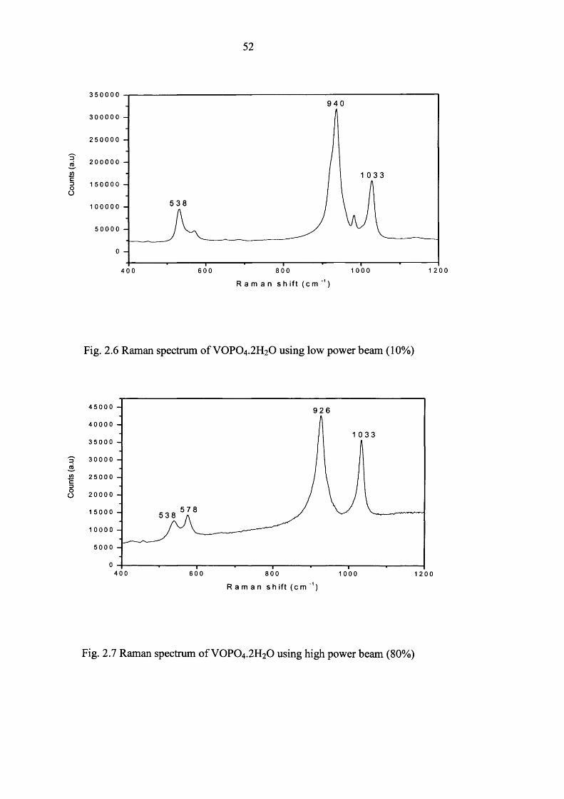
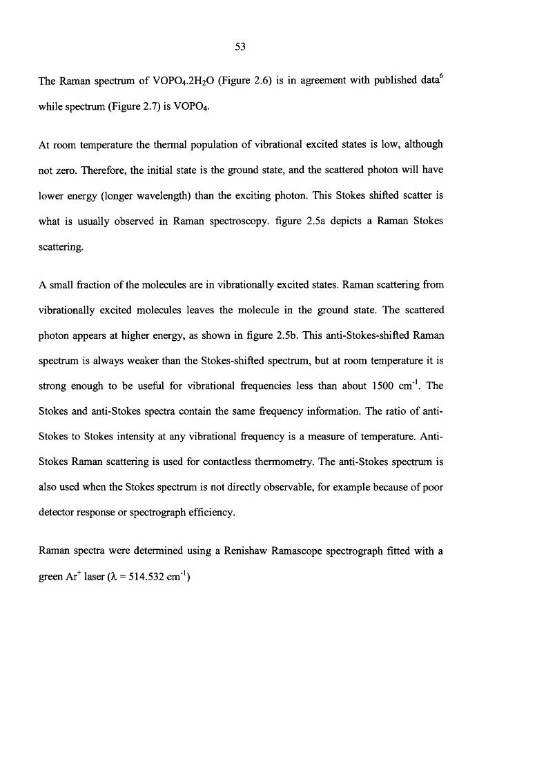
measurable temperature rise in a material. It is known that material such as VOPO4 .2 H2O
can dehydrate. Therefore, a low power (10%) beam was used for characterizing VPO
materials. Raman spectrums o f VOPO4 .2 H2O obtained using different power (10% and
80%) are shown in figure 2.6 and 2.7 respectively.
Coun
ts
(a.u
) Co
unts
(a
.u)
52
3 5 0 0 0 09 4 0
3 0 0 0 0 0 -
2 5 0 0 0 0 -
2 0 0 0 0 0 -
1 0 3 31 5 0 0 0 0 -
5 3 81 0 0 0 0 0 -
5 0 0 0 0 -
1 2 0 08 0 0 1 0 0 04 0 0 6 0 0
R a m a n s h ift ( c m 1)
Fig. 2.6 Raman spectrum o f VOPO4 .2 H2O using low power beam (10%)
4 5 0 0 0 9 2 6
4 0 0 0 0
1 0 3 33 5 0 0 0
3 0 0 0 0
2 5 0 0 0
2 0 0 0 0
5 7 81 5 0 0 0 5 3 8
1 0 0 0 0
5 0 0 0
4 0 0 6 0 0 8 0 0 1 0 0 0 1 2 0 0
R a m a n s h ift ( c m ' 1)
Fig. 2.7 Raman spectrum o f VOPO4 .2 H2O using high power beam (80%)
53
The Raman spectrum o f VOPO4 .2 H2O (Figure 2.6) is in agreement with published data6
while spectrum (Figure 2.7) is VOPO4 .
At room temperature the thermal population o f vibrational excited states is low, although
not zero. Therefore, the initial state is the ground state, and the scattered photon will have
lower energy (longer wavelength) than the exciting photon. This Stokes shifted scatter is
what is usually observed in Raman spectroscopy, figure 2.5a depicts a Raman Stokes
scattering.
A small fraction o f the molecules are in vibrationally excited states. Raman scattering from
vibrationally excited molecules leaves the molecule in the ground state. The scattered
photon appears at higher energy, as shown in figure 2.5b. This anti-Stokes-shifted Raman
spectrum is always weaker than the Stokes-shifted spectrum, but at room temperature it is
strong enough to be useful for vibrational frequencies less than about 1500 cm'1. The
Stokes and anti-Stokes spectra contain the same frequency information. The ratio o f anti-
Stokes to Stokes intensity at any vibrational frequency is a measure o f temperature. Anti-
Stokes Raman scattering is used for contactless thermometry. The anti-Stokes spectrum is
also used when the Stokes spectrum is not directly observable, for example because o f poor
detector response or spectrograph efficiency.
Raman spectra were determined using a Renishaw Ramascope spectrograph fitted with a
green Ar+ laser (k = 514.532 cm'1)

54
2.3.3 Electron microscope (SEM and TEM)
The SEM is a type o f electron microscope capable o f producing high-resolution images o f a
sample surface. Due to the manner in which the image is created, SEM images have a
characteristic three-dimensional appearance and useful for judging the surface structure o f
the sample.
In a typical SEM, electrons are emitted from a tungsten or lanthanum hexaboride (LaB6)
cathode and are accelerated towards an anode; alternatively, electrons can be emitted via
field emission (FE). Tungsten is used because it has the highest melting point and lowest
vapor pressure o f all metals, thereby allowing it to be heated for electron emission. The
electron beam, which typically has an energy ranging from a few hundred eV to 100 keV, is
focused by one or two condenser lenses into a beam with a very fine focal spot sized 1 nm
to 5 nm. When the primary electron beam interacts with the sample, the electrons lose
energy by repeated scattering and absorption within a teardrop shaped volume o f the
specimen known as the interaction volume, which extends from less than 1 0 0 nm to around
5 |im into the surface. The size o f the interaction volume depends on the beam accelerating
voltage, the atomic number o f the specimen and the specimen’s density.
The energy exchange between the electron beam and the sample results in the emission o f
electrons and electromagnetic radiation which can be detected to produce an image, the
most common imaging mode monitors low energy (<50 eV) secondary electrons. Due to
their low energy, these electrons originate within a few nanometers from the surface. The
electrons are detected by a scintillator-photomultiplier device and the resulting signal is
rendered into a two-dimensional intensity distribution that can be viewed and saved as a
digital image. The brightness o f the signal depends on the number o f secondary electrons
55
reaching the detector. If the beam enters the sample perpendicular to the surface, then the
activated region is uniform about the axis o f the beam and a certain number o f electrons
escape from within sample. As the angle o f incidence increases, the escape distance o f one
side o f the beam will decrease, and more secondary electrons will be emitted. Thus steep
surfaces and edges tend to be brighter than flat surfaces, which results in images with a
well-defined, three-dimensional appearance. Using this technique, resolutions o f less than 1
nm are possible.
Images can be obtained due to the backscattered electrons (BSE) which consist o f high-
energy electrons originating in the electron beam, that are reflected or back-scattered out o f
the specimen interaction volume. Backscattered electrons may be used to detect contrast
between areas with different chemical compositions, especially when the average atomic
number o f the various regions is different, since the brightness o f the BSE image tends to
n
increase with the atomic number.
Backscattered electrons can also be used to form electron backscatter diffraction (EBSD)
image. This image can be used to determine the crystallographic structure o f the specimen.
SEM images were obtained using FEI XL 30 E.S.E.M instrument, at Earth Science
Department, Cardiff University
TEM images were obtained by Prof. Chris Kiely and Dr. Andy Burrows in the materials
science department at the Lehigh University, USA. Samples for transmission electron
microscopy (TEM) examination were prepared by dispersing the catalyst powder in high
purity ethanol, then allowing a drop o f the suspension to evaporate on a holey carbon film
supported on a 300 mesh copper TEM grid. TEM analyses were carried out in a 200kV
JEOL 2000FX electron microscope equipped with a thermionic LaB6 source.
56
2.3.4 Surface area measurement
Surface area is an attribute that is used by catalyst manufacturers and users to monitor the
activity and stability o f catalysts. There are different methods used to measure surface area
and each method can yield different results. Most methods are based on the isothermal
adsorption o f nitrogen. Either a single point or multipoint method is used to calculate the
surface area. The multipoint Brunauer, Emmett and Teller method is used to measure total
surface area o f catalyst, and is described in the following equation:
Where V is the volume, reduced to standard conditions (STP) o f gas adsorbed per unit mass
o f adsorbent at a given pressure P and constant temperature, Vm is the volume o f gas
adsorbed at STP per unit mass o f adsorbent necessary to form a complete monolayer on the
surface, PQ is the saturation pressure at the measurement temperature, and C is a constant.
A linear relationship is obtained when P/[V(Po- P)] is plotted against P/ Po, and the values
o f Vm and C can be obtained from the slope and intercept.
The surface area (SA) can be calculated based on the following equation
Eq. 2.6V (P o -P ) VmC VmC P0
SA = (Vm * L * Am) / Vmol Eq. 2.7
Where L is the Avogadro constant, Am is the average area occupied by the adsorbate in the
filled monolayer (0.162 nm2 for N 2) and Vmoi is the molar volume o f adsorbed gas at STP .8
57
Surface area measurements were carried out using a Micromeritics ASAP 2010 instrument,
and N2 was used as the adsorptive.
2.4 References
(1) J. W. Johnson, D.C. Johnston, A. J. Jacobson and J. F. Brody, J. Am. Chem. Soc.,
1884,106,8123
(2) M. T. Sananes, I. J. Ellison, S. Sajip, A. Burrows, C. J. Kiely, J. C. Volta and G. J.
Hutchings, J. Chem. Soc., Faraday Trans., 1996, 92(1), 137
(3) Y. Kamiya, S. Ueki, N. Hiyoshi , N. Yamamoto and T. Okuhara, Catalysis Today,
2003,78, 281
(4) Ira. N. Levine, Physical Chemistry fourth edition, 1995
(5) Gordon. M. Barrow, Physical Chemistry fifth edition, 1988
(6 ) E. Bordes, Catal. Today, 1994, 16
(7) L. E. Smart, E. A. Moore, Solid State Chemistry, third edition, 2005
(8 ) P. W. Atkins, Physical Chemistry, seventh edition, 2001

58
Chapter 3
Control the Morphology of Vanadium Phosphate
Catalyst Precursors by Adding Alkane Solvents
3.1 Introduction
The selective oxidation of of «-butane to maleic anhydride using vanadium phosphate catalysts
has been well studied in recent years.1'5 The reaction and catalysts continue to attract attention
as it represents one o f the few examples o f the selective activation o f an alkane at elevated
temperatures. In particular, the structure and activity o f vanadium phosphates has been
extensively studied and continues to attract attention. The catalytic performance o f vanadium
phosphates depends on the method o f preparation o f the catalyst precursor, VOHPO4.O.5H2O6'
, and the reaction conditions utilised for the in situ activation in /2-butane/air to form the final
catalyst.6,7 The active catalyst comprises (V0)2P207 in combination with some V5+ phosphates,
typically oti- and 8-VOPO4, and the transformation o f the precursor to the final catalyst is
topotactic. Hence, the morphology o f the precursor is o f crucial importance in determining the
eventual catalyst morphology and the performance following activation. In view o f the
importance o f the morphology o f the catalyst precursor, there have been numerous studies
concerned with catalyst preparation. However, most studies use a standard preparation method
in which V2O5 is used as a source o f vanadium and H3PO4 is used as a source o f phosphorus,
and an alcohol is used as the reducing agent that is required to synthesise the V4+ precursor

59
phase. Notably, the addition o f a solvent to this preparation procedure has not been considered
in detail in any scientific publications and patents.
Recently, Okuhara and co-workers reported that intercalation and exfoliation o f VOPO4 .2 H2O
crystallites proceeded with a stepwise heating below refluxing temperature in primary and
secondary alcohols and the subsequent reduction o f the exfoliated VOPO4.2 H2O brought about
VOHPO4 .O.5 H2O crystallites with different morphologies. Furthermore, (VO)2P2C>7 obtained
from the precursor was highly active and selective for the selective oxidation o f n-butane.21'25
Vanadium phosphate catalysts prepared by the reduction o f VOPO4 .2 H2O with 1-butanol are
described and discussed in this chapter. In particular, the effect o f the addition o f an alkane
during the reflux stage o f the preparation has been investigated and these changes are
demonstrated that the presence o f a solvent can induce significant effects on both the structure
and morphology o f the vanadium phosphate.
3.2 Experimental
VOPO4 .2 H2O (1.0 g) was refluxed with 1-butanol (25 ml) and different quantities o f alkane
solvents for 24 hours, and the resulting material was recovered by filtration, (more details in
Chapter 2)
60
VOPO4 2 H2O (V: alcohol = 1: 50) was refluxed in different quantities o f the alcohols (1-
butanol and 1-octanol) and octane solvent total volume up to 175 ml for 24 hours. The
resulting material was recovered by vacuum filtration and washed with alcohol (50 ml) and
acetone (50 ml) and dried in air at 110°C for 24 hours.
VOPO4 2 H2O (lg ) was refluxed o f in different quantities o f the alcohols ( 1-butanol and 1-
octanol ) and octane solvent total volume up to 175 ml for 24 h. The resulting material was
recovered by vacuum filtration and washed with alcohol (50 ml) and acetone (50 ml) and dried
in air at 110°C for 24 hours.
The new materials were activated in situ to give final catalysts and these materials were tested
for the oxidation o f n-butane to maleic anhydride. The precursors, catalysts were characterised
using a combination of powder X-ray diffraction, laser Raman spectroscopy, BET surface area
measurements, scanning electron microscopy and transmission electron microscopy.
3.3 Results
Characterisation of new materials prepared by reacting of V0 P0 4 ,2 H20
with 1- butanol and differing amount of octane solvent
The XRD, laser Raman spectrum and SEM of new materials prepared using different amount
of (10, 25, 50, 100, 400 ml) octane solvents are shown in Figure 3.1, 3.2 and 3.3 respectively.
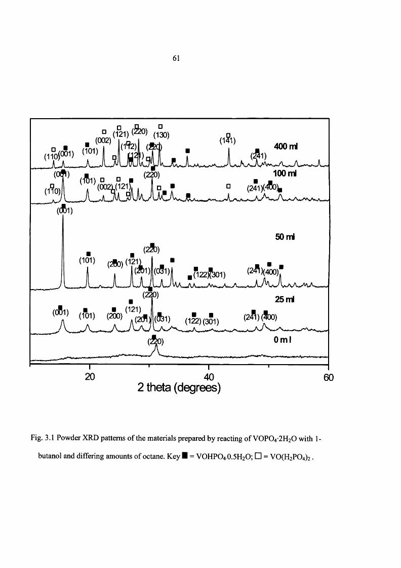
61
(121) (130)(002)
100 rrri(0021.(121),
50 ml
$ 1H _ * 22^ 301)
25 ml■ ■ (121)
(101) (200) J f l j(122) (301)
0ml
402 theta (degrees)
Fig. 3.1 Powder XRD patterns o f the materials prepared by reacting o f VOP0 4 -2 H20 with 1-
butanol and differing amounts o f octane. Key I = VOHPO4 O.5 H2O; □ = VO(H2PC>4)2 .
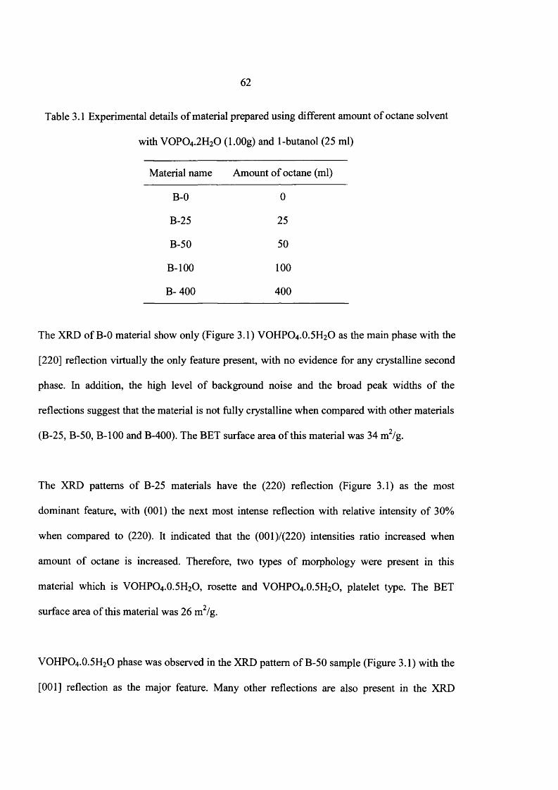
62
Table 3.1 Experimental details o f material prepared using different amount o f octane solvent
with VOPO4 .2 H2O (l.OOg) and 1-butanol (25 ml)
Material name Amount o f octane (ml)
B-0 0
B-25 25
B-50 50
B-100 100
B- 400 400
The XRD of B-0 material show only (Figure 3.1) VOHPO4 .O.5 H2O as the main phase with the
[220] reflection virtually the only feature present, with no evidence for any crystalline second
phase. In addition, the high level o f background noise and the broad peak widths o f the
reflections suggest that the material is not fully crystalline when compared with other materials
(B-25, B-50, B-100 and B-400). The BET surface area o f this material was 34 m2/g.
The XRD patterns o f B-25 materials have the (220) reflection (Figure 3.1) as the most
dominant feature, with (001) the next most intense reflection with relative intensity o f 30%
when compared to (220). It indicated that the (001)/(220) intensities ratio increased when
amount o f octane is increased. Therefore, two types o f morphology were present in this
material which is VOHPO4 .O.5 H2O, rosette and VOHPO4 .O.5 H2O, platelet type. The BET
surface area o f this material was 26 m2/g.
VOHPO4 .O.5 H2O phase was observed in the XRD pattern o f B-50 sample (Figure 3.1) with the
[001] reflection as the major feature. Many other reflections are also present in the XRD
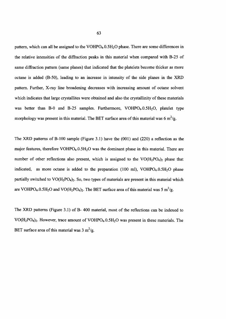
63
pattern, which can all be assigned to the VOHPO4 .O.5 H2O phase. There are some differences in
the relative intensities o f the diffraction peaks in this material when compared with B-25 of
same diffraction pattern (same planes) that indicated that the platelets become thicker as more
octane is added (B-50), leading to an increase in intensity o f the side planes in the XRD
pattern. Further, X-ray line broadening decreases with increasing amount of octane solvent
which indicates that large crystallites were obtained and also the crystallinity of these materials
was better than B-0 and B-25 samples. Furthermore, VOHPO4 .O.5 H2O, platelet type
morphology was present in this material. The BET surface area o f this material was 6 m2/g.
The XRD patterns o f B-100 sample (Figure 3.1) have the (001) and (220) a reflection as the
major features, therefore VOHPO4 .O.5 H2O was the dominant phase in this material. There are
number o f other reflections also present, which is assigned to the VO(H2PC>4)2 phase that
indicated, as more octane is added to the preparation (100 ml), VOHPO4 .O.5 H2O phase
partially switched to V0 (H2P0 4 )2. So, two types o f materials are present in this material which
are VOHPO4 .O.5 H2O and V0 (H2P0 4 )2. The BET surface area o f this material was 5 m2/g.
The XRD patterns (Figure 3.1) o f B- 400 material, most o f the reflections can be indexed to
V0(H 2P 0 4)2. However, trace amount o f VOHPO4 .O.5 H2O was present in these materials. The
BET surface area o f this material was 3 m2/g.

64
(936)B-400
(986) (937^ J (986)
B-100
(986)B-5Q
B-25(986)
B-0
400 600 800 1000 1200 1400
Raman shift (cm'1)
Fig. 3.2 Raman spectrum of the materials formed by reacting o f V0 P0 4 -2 H20 with 1-butanol
and differing amounts of octane solvent.
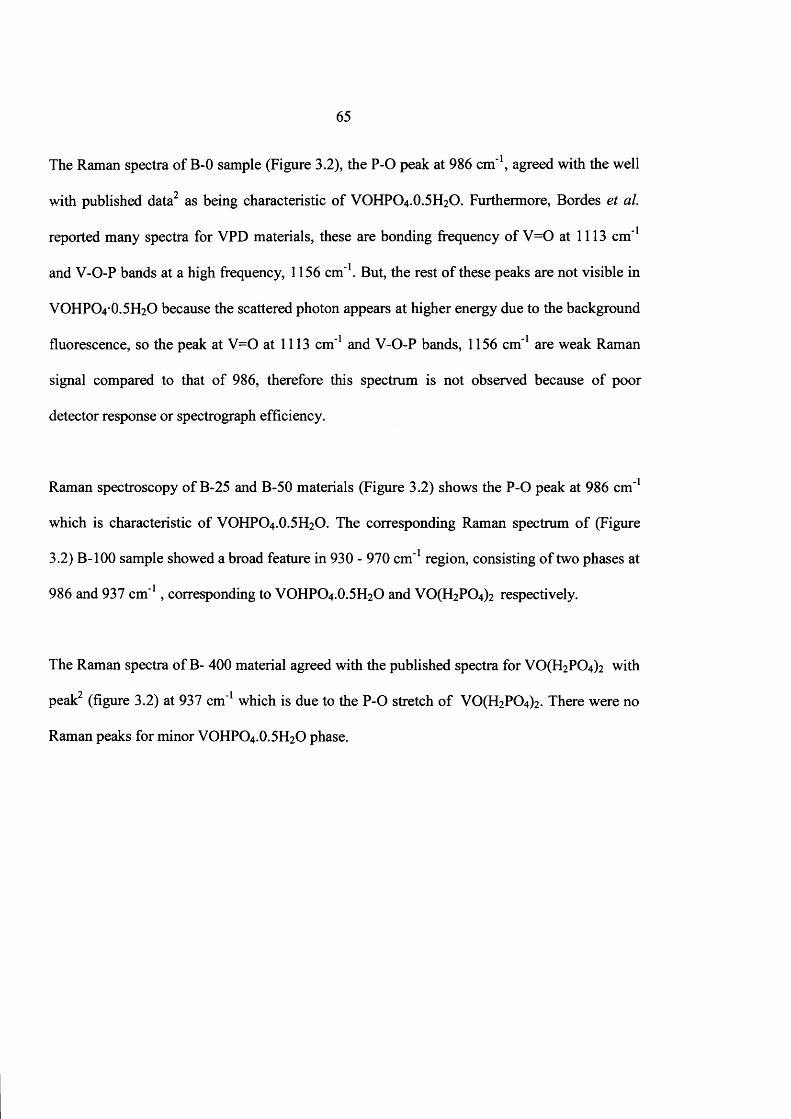
65
The Raman spectra o f B-0 sample (Figure 3.2), the P-O peak at 986 cm"1, agreed with the well
with published data2 as being characteristic of VOHPO4 .O.5 H2O. Furthermore, Bordes et al.
reported many spectra for VPD materials, these are bonding frequency o f V = 0 at 1113 cm'1
and V-O-P bands at a high frequency, 1156 cm'1. But, the rest o f these peaks are not visible in
VOHPO4 O.5 H2O because the scattered photon appears at higher energy due to the background
fluorescence, so the peak at V =0 at 1113 cm'1 and V-O-P bands, 1156 cm'1 are weak Raman
signal compared to that o f 986, therefore this spectrum is not observed because o f poor
detector response or spectrograph efficiency.
Raman spectroscopy o f B-25 and B-50 materials (Figure 3.2) shows the P -0 peak at 986 cm'1
which is characteristic o f VOHPO4 .O.5 H2O. The corresponding Raman spectrum o f (Figure
3.2) B-100 sample showed a broad feature in 930 - 970 cm'1 region, consisting o f two phases at
986 and 937 cm'1, corresponding to VOHPO4 .O.5 H2O and VO(H2P0 4 ) 2 respectively.
The Raman spectra o f B- 400 material agreed with the published spectra for V0 (H2P0 4 ) 2 with
peak2 (figure 3.2) at 937 cm'1 which is due to the P -0 stretch o f V0 (H2P0 4 )2 . There were no
Raman peaks for minor VOHPO4.O.5 H2O phase.
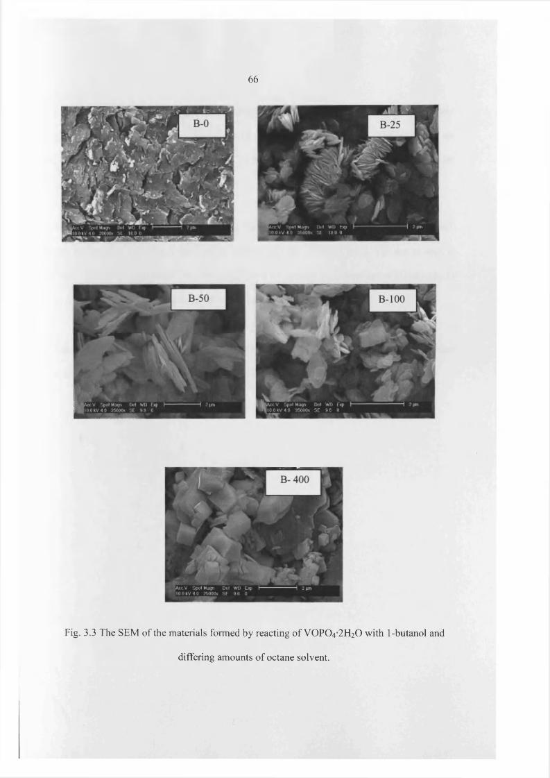
66
Fig. 3.3 The SEM of the materials formed by reacting of VOPO4 2 H2O with 1-butanol and
differing amounts of octane solvent.
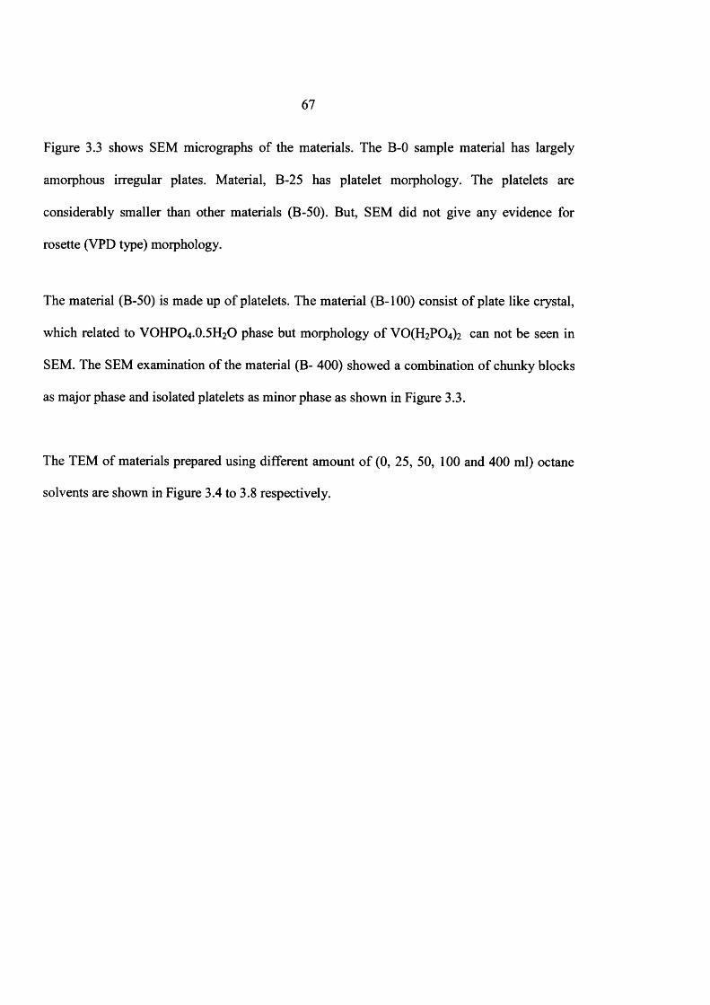
67
Figure 3.3 shows SEM micrographs o f the materials. The B-0 sample material has largely
amorphous irregular plates. Material, B-25 has platelet morphology. The platelets are
considerably smaller than other materials (B-50). But, SEM did not give any evidence for
rosette (VPD type) morphology.
The material (B-50) is made up o f platelets. The material (B-100) consist o f plate like crystal,
which related to VOHPO4.O.5 H2O phase but morphology o f VCXFbPO^ can not be seen in
SEM. The SEM examination o f the material (B- 400) showed a combination o f chunky blocks
as major phase and isolated platelets as minor phase as shown in Figure 3.3.
The TEM of materials prepared using different amount o f (0, 25, 50, 100 and 400 ml) octane
solvents are shown in Figure 3.4 to 3.8 respectively.

68
0 5 pm
0.5 pm
Fig. 3.4 The TEM of B-0 material
TEM examination of the B-0 sample revealed that irregular amorphous platelets as shown in
Figure 3.4a. But, there were no [hkl] planes were observed from the diffuse amorphous
diffraction pattern (figure 3.4b) of irregular amorphous platelet. Further, this material also has
irregular disordered platelet as shown in figure 3.4c. Finally, diffraction pattern (figure 3.4 d)
of the disordered platelet shows some evidence of limited crystallinity in this material.
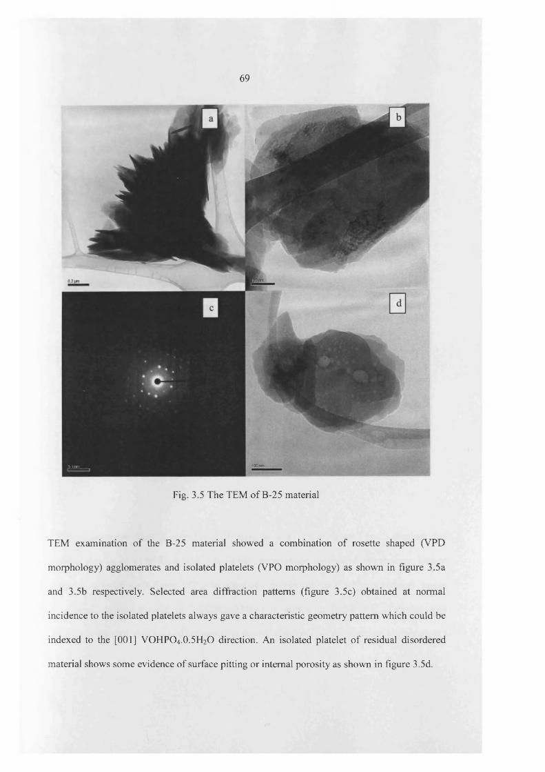
69
Fig. 3.5 The TEM of B-25 material
TEM examination of the B-25 material showed a combination of rosette shaped (VPD
morphology) agglomerates and isolated platelets (VPO morphology) as shown in figure 3.5a
and 3.5b respectively. Selected area diffraction patterns (figure 3.5c) obtained at normal
incidence to the isolated platelets always gave a characteristic geometry pattern which could be
indexed to the [001] VOHPO4.0.5H2O direction. An isolated platelet of residual disordered
material shows some evidence of surface pitting or internal porosity as shown in figure 3.5d.
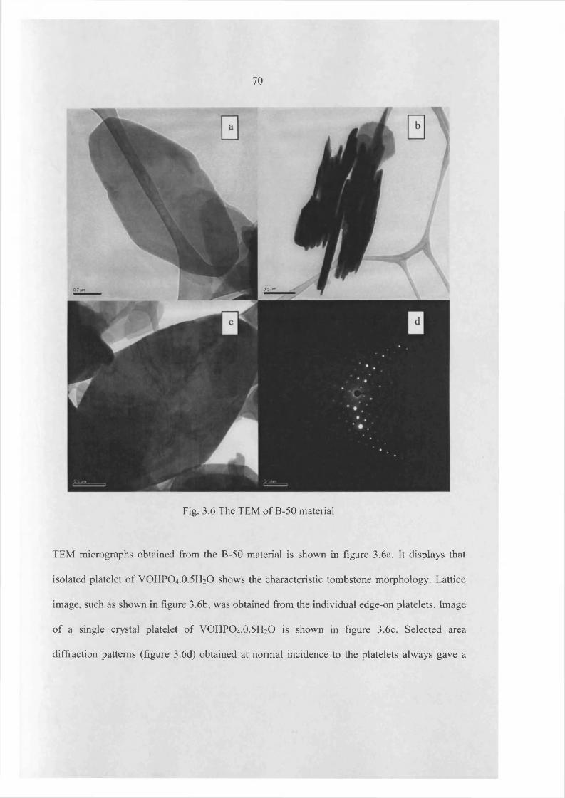
70
0.5 jm0.2
Fig. 3.6 The TEM of B-50 material
TEM micrographs obtained from the B-50 material is shown in figure 3.6a. It displays that
isolated platelet of VOHPO4 .O.5 H2O shows the characteristic tombstone morphology. Lattice
image, such as shown in figure 3.6b, was obtained from the individual edge-on platelets. Image
of a single crystal platelet of VOHPO4.O.5 H2O is shown in figure 3.6c. Selected area
diffraction patterns (figure 3.6d) obtained at normal incidence to the platelets always gave a
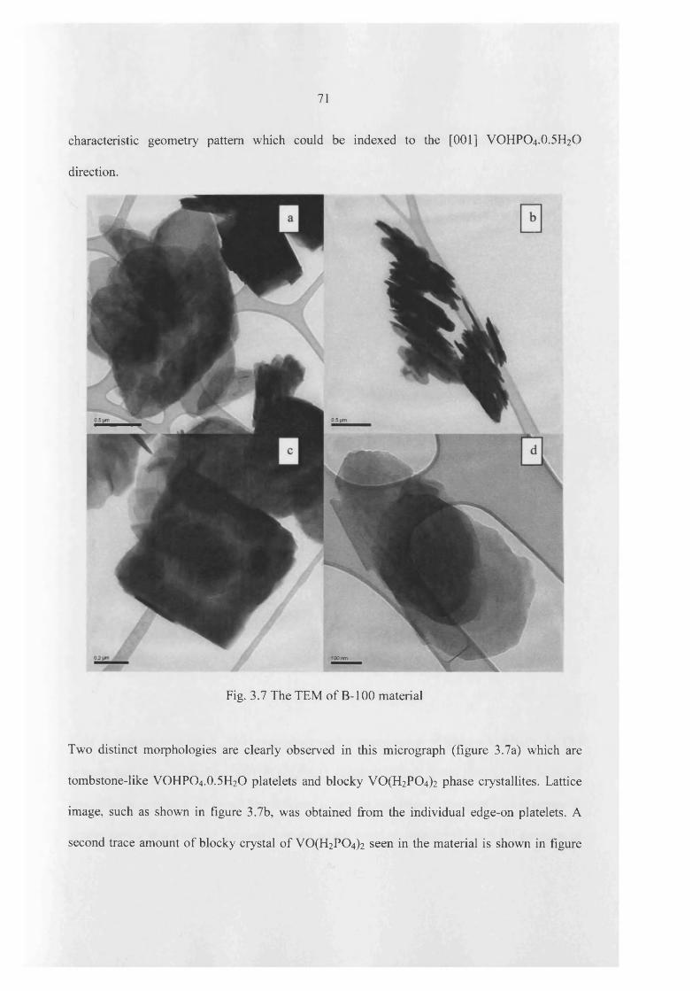
71
characteristic geometry pattern which could be indexed to the [001] VOHPO4 .O.5 H2O
direction.
0.2
Fig. 3.7 The TEM of B -100 material
Two distinct morphologies are clearly observed in this micrograph (figure 3.7a) which are
tombstone-like VOHPO4.0.5H2O platelets and blocky V 0 (H2P0 4 ) 2 phase crystallites. Lattice
image, such as shown in figure 3.7b, was obtained from the individual edge-on platelets. A
second trace amount o f blocky crystal o f VO(H2PC>4)2 seen in the material is shown in figure
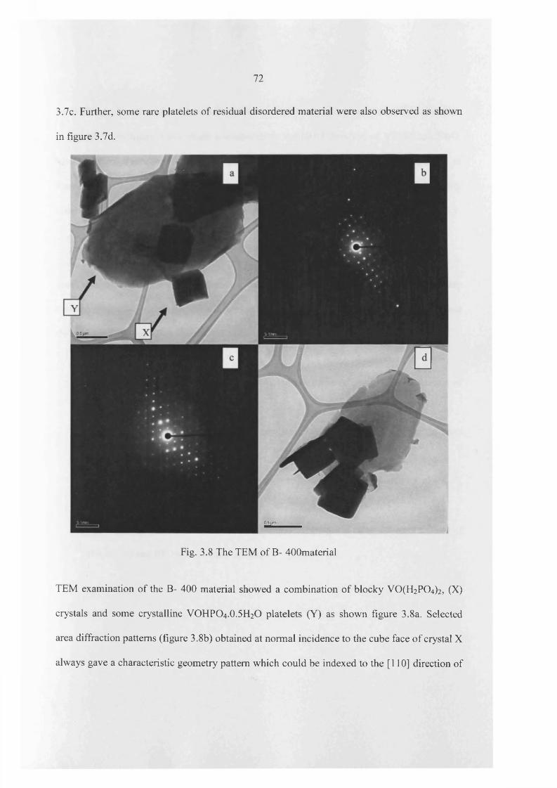
72
3.7c. Further, some rare platelets of residual disordered material were also observed as shown
in figure 3.7d.
05tim
Fig. 3.8 The TEM of B- 400material
TEM examination of the B- 400 material showed a combination of blocky V0 (H2P0 4 )2, (X)
crystals and some crystalline VOHPO4.0.5H2O platelets (Y) as shown figure 3.8a. Selected
area diffraction patterns (figure 3.8b) obtained at normal incidence to the cube face o f crystal X
always gave a characteristic geometry pattern which could be indexed to the [110] direction of

73
VO(H2P 04)2. Based on the selected area diffraction pattern in the platelet at normal direction
of crystal Y (in figure 3.8a) which corresponds to the [001] direction o f VOHPC>4.0.5H2C).
Micrograph of figure 3.8d shows that B- 400 material has a mixture o f residual platelet of
disordered material and blocky crystallites. Therefore, three distinct morphologies are clearly
observed in this material which is platelet, disordered platelet and blocky crystal.
Finally, heptane, dodecane and hexadecane were used for this investigation. The relationship
between morphology changes and the amount of alkane used are shown in Table 3.2. These
changes are shown in XRD, Raman and SEM, corresponding to the following Appendix.
(1) Appendix 3.1 - The XRD patterns o f new materials prepared using different amount of
(0, 25, 50 and 100 ml) heptane solvent
(2) Appendix 3.2 - The Raman spectrum of new materials prepared using different amount
of (0, 25, 50 and 100 ml) heptane solvent
(3) Appendix 3.3 - The SEM of new materials prepared using different amount o f (0, 25,
50 and 100 ml) heptane solvent
(4) Appendix 3.4 - The XRD patterns o f new materials prepared using different amount of
(10, 25, 50 and 100 ml) dodecane solvent

74
(5) Appendix 3.5 - The Raman spectrum of new materials prepared using different amount
of (10, 25, 50 and 100 ml) dodecane solvent
(6) Appendix 3.6 - The SEM of new materials prepared using different amount of (10, 25,
50 and 100 ml) dodecane solvent
(7) Appendix 3.7 - The XRD patterns o f new materials prepared using different amount of
(10, 25, 50, 75 and 100 ml) hexadecane solvent
(8) Appendix 3.8 - The Raman spectrum of new materials prepared using different amount
of (10, 25, 50, 75 and 100 ml) hexadecane solvent
(9) Appendix 3.9 - The SEM of new materials prepared using different amount of (10, 25,
50, 75 and 100 ml) hexadecane solvent
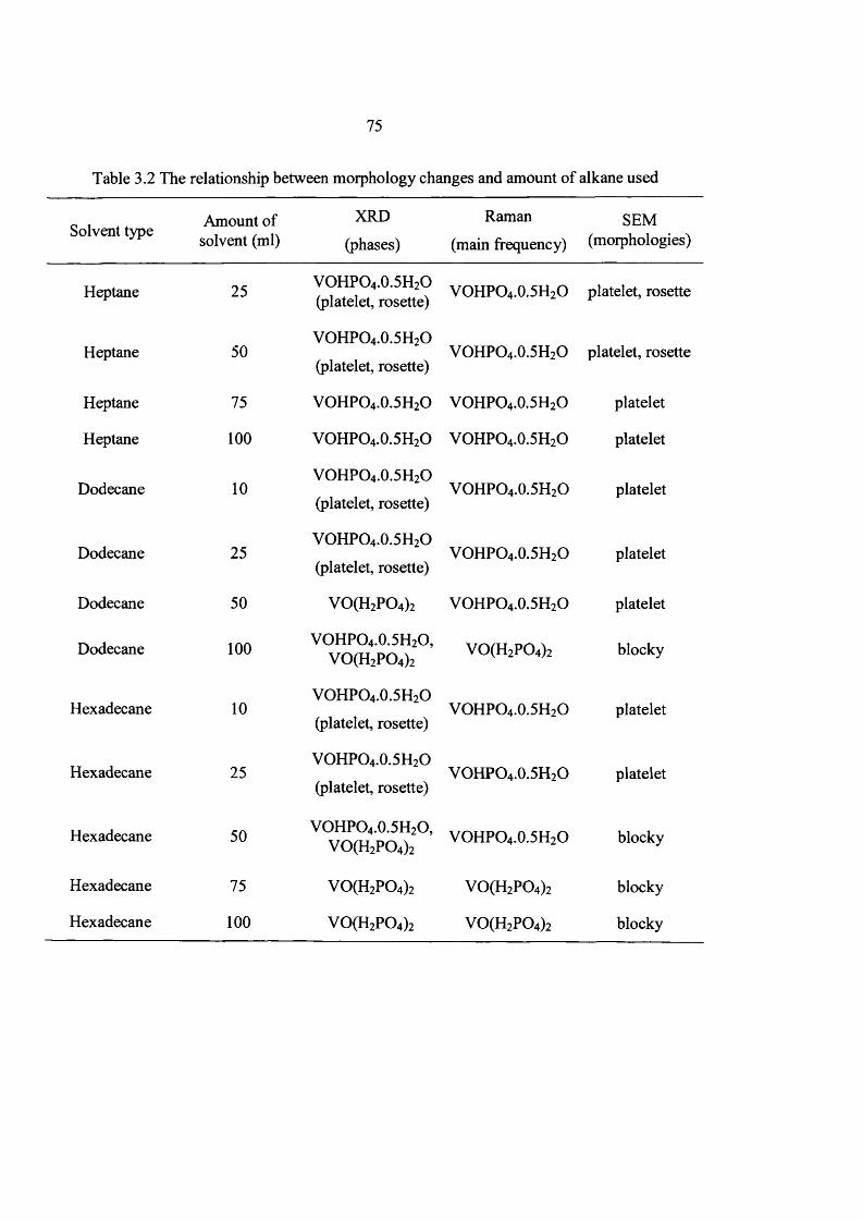
75
Table 3.2 The relationship between morphology changes and amount of alkane used
Solvent type Amount of solvent (ml)
XRD
(phases)
Raman
(main frequency)SEM
(morphologies)
Heptane 25 VOHPO4.0.5H2O (platelet, rosette)
VOHPO4.0.5H2O platelet, rosette
Heptane 50VOHPO4.0.5H2O
(platelet, rosette)VOHPO4.0.5H2O platelet, rosette
Heptane 75 VOHPO4.0.5H2O VOHPO4.0.5H2O platelet
Heptane 100 VOHPO4.0.5H2O VOHPO4.0.5H2O platelet
Dodecane 10VOHPO4.0.5H2O
(platelet, rosette)VOHPO4.0.5H2O platelet
Dodecane 25VOHPO4.0.5H2O
(platelet, rosette)VOHPO4.0.5H2O platelet
Dodecane 50 V 0(H 2P 0 4)2 VOHPO4.0.5H2O platelet
Dodecane 100 VOHPO4.0.5H2O,V 0(H 2P 0 4)2 VO(H2P 0 4)2 blocky
Hexadecane 10VOHPO4.0.5H2O
(platelet, rosette)VOHPO4.0.5H2O platelet
Hexadecane 25VOHPO4.0.5H2O
(platelet, rosette)VOHPO4.0.5H2O platelet
Hexadecane 50 VOHPO4.0.5H2O,V 0(H 2P 0 4)2 VOHPO4.0.5H2O blocky
Hexadecane 75 V 0(H 2P 0 4)2 VO(H2P 0 4)2 blocky
Hexadecane 100 V 0(H 2P 0 4)2 VO(H2P 0 4)2 blocky

76
When alonger chain alkane (dodecane, hexadecane) were used, the same changes were
observed but these changes were observed using smaller amounts o f higher boiling temperature
alkane. A mixture o f VPD and VPO type materials were obtained when 10 ml o f hexadecane
or dodecane solvent was used. These changes have shown in XRD patterns with (220) and
(001) as the main peaks of the materials (Appendix 3.7 and Appendix 3.4), the peaks are
assigned to mixture o f rosette and platelet morphology o f the materials, but SEM (Appendix
3.9 and Appendix 3.6) only indicated that materials have platelet morphology. Further, mixture
o f rosette and platelet morphology o f the material were obtained by using 25 ml of octane
solvent that indicating, longer chain alkanes (dodecane, hexadecane) switch the morphology of
these materials with smaller amounts o f alkane solvent as compared with short chain alkane
solvent (octane, heptane). Additionally, in the case o f heptane solvent, these changes were
observed with using high amount o f heptane solvent and SEM (Appendix 3.3) o f the material
clearly indicated that mixture o f rosette and platelet morphology was observed when 25 and 50
ml of heptane was introduced. Surface area o f these materials gave same results that platelet
morphology materials were between 8-16 m2/g and blocky or chunky morphology materials
were between 1-3 m2/g. However, the surface area o f the mixture o f platelet and rosette
morphology materials was higher than o f other materials; 18-32 m2/g.
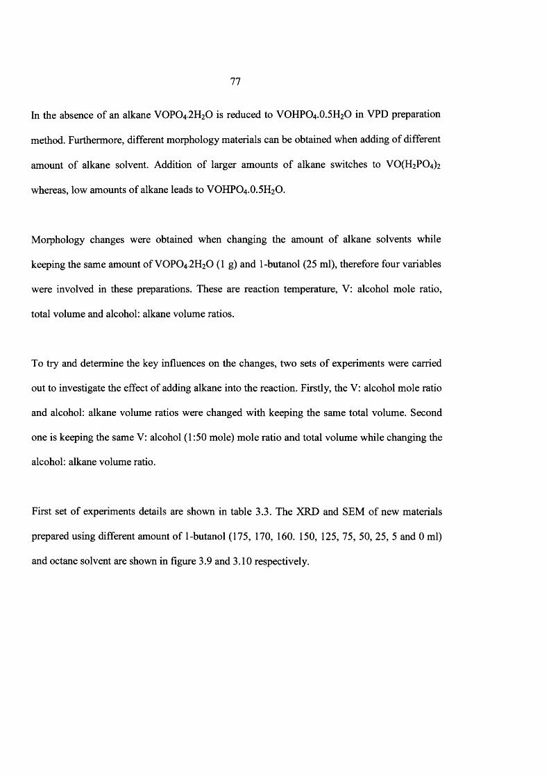
77
In the absence o f an alkane VOPO4.2 H2O is reduced to VOHPO4 .O.5 H2O in VPD preparation
method. Furthermore, different morphology materials can be obtained when adding o f different
amount o f alkane solvent. Addition o f larger amounts o f alkane switches to V0 (H2P0 4 ) 2
whereas, low amounts of alkane leads to VOHPO4 .O.5 H2O.
Morphology changes were obtained when changing the amount o f alkane solvents while
keeping the same amount of VOPO4.2 H2O (1 g) and 1-butanol (25 ml), therefore four variables
were involved in these preparations. These are reaction temperature, V: alcohol mole ratio,
total volume and alcohol: alkane volume ratios.
To try and determine the key influences on the changes, two sets o f experiments were carried
out to investigate the effect of adding alkane into the reaction. Firstly, the V: alcohol mole ratio
and alcohol: alkane volume ratios were changed with keeping the same total volume. Second
one is keeping the same V: alcohol (1:50 mole) mole ratio and total volume while changing the
alcohol: alkane volume ratio.
First set o f experiments details are shown in table 3.3. The XRD and SEM of new materials
prepared using different amount o f 1-butanol (175, 170, 160. 150, 125, 75, 50, 25, 5 and 0 ml)
and octane solvent are shown in figure 3.9 and 3.10 respectively.

78
Table 3.3 - Experimental details o f material prepared using different amount o f 1-butanol and
octane solvent with VOPO4 .2 H2O (1 g)
Materialname
Mass of VOPO4.2 H2O
(g)
V:OH mole ratio
1 -Butanol (ml)
Octane(ml)
Bl-175 1 1:350 175 0
Bl-170 1 1:340 170 5
Bl-160 1 1:320 160 15
Bl-150 1 1:300 150 25
Bl-125 1 1:250 125 50
Bl-75 1 1:150 75 1 0 0
Bl-50 1 1 : 1 0 0 50 125
Bl-25 1 1:50 25 150
Bl-5 1 1 : 2 0 5 170
B l-0 1 0 175

79
(200)(001) ( 101) B1 -0(002)
(200) (12V20 l f ? , - > 1°2) B1 -5
B1 -25
B1 -50(101) (220)B (200) (1211(201)1 ; 3 (102) B1 -75
B1-125
B1 -150
B1-175
20 40 602 theta (degrees)
Fig. 3.9 The XRD of new materials prepared using different amount o f 1-butanol and octane
solvent. Key ■ = VOHP04 0.5H2O; □ = Y 0 P 0 4.2H20
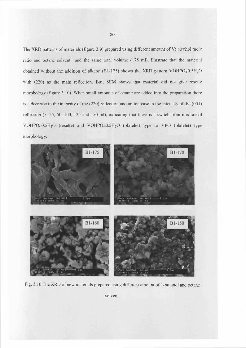
80
The XRD patterns of materials (figure 3.9) prepared using different amount of V: alcohol mole
ratio and octane solvent and the same total volume (175 ml), illustrate that the material
obtained without the addition of alkane (B 1-175) shows the XRD pattern VOHPO4.O.5 H2O
with (220) as the main reflection. But, SEM shows that material did not give rosette
morphology (figure 3.10). When small amounts of octane are added into the preparation there
is a decrease in the intensity of the (220) reflection and an increase in the intensity of the (001)
reflection (5, 25, 50, 100, 125 and 150 ml), indicating that there is a switch from mixture of
VOHPO40.5H2O (rosette) and VOHPO4 O.5 H2O (platelet) type to VPO (platelet) type
morphology.
Fig. 3.10 The XRD of new materials prepared using different amount o f 1-butanol and octane
solvent
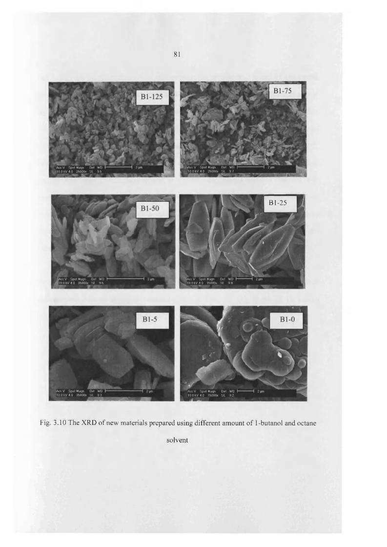
81
Bl-25
Fig. 3.10 The XRD of new materials prepared using different amount of 1-butanol and octane
solvent
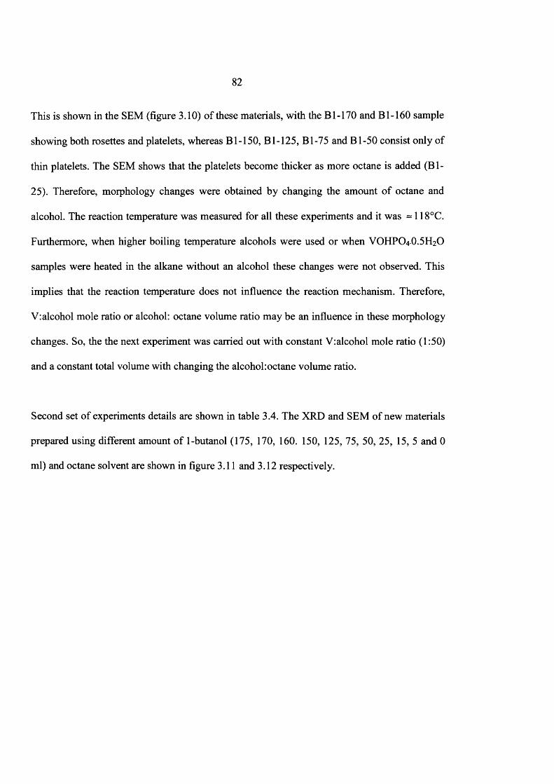
82
This is shown in the SEM (figure 3.10) of these materials, with the B1-170 and B 1-160 sample
showing both rosettes and platelets, whereas Bl-150, B 1-125, Bl-75 and B l-50 consist only of
thin platelets. The SEM shows that the platelets become thicker as more octane is added (B l-
25). Therefore, morphology changes were obtained by changing the amount o f octane and
alcohol. The reaction temperature was measured for all these experiments and it was « 1 1 8°C.
Furthermore, when higher boiling temperature alcohols were used or when VOHPO4 O.5 H2O
samples were heated in the alkane without an alcohol these changes were not observed. This
implies that the reaction temperature does not influence the reaction mechanism. Therefore,
V:alcohol mole ratio or alcohol: octane volume ratio may be an influence in these morphology
changes. So, the the next experiment was carried out with constant V:alcohol mole ratio (1:50)
and a constant total volume with changing the alcohol:octane volume ratio.
Second set o f experiments details are shown in table 3.4. The XRD and SEM of new materials
prepared using different amount o f 1-butanol (175, 170, 160. 150, 125, 75, 50, 25, 15, 5 and 0
ml) and octane solvent are shown in figure 3.11 and 3.12 respectively.
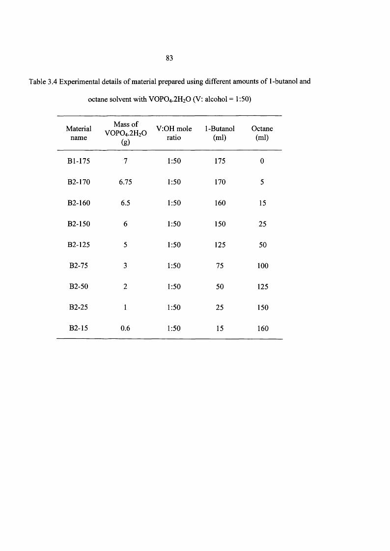
83
Table 3.4 Experimental details o f material prepared using different amounts o f 1-butanol and
octane solvent with VOPO4 .2 H2O (V: alcohol = 1:50)
Materialname
Mass of V 0 P 0 4.2H20
(g)
V:OH mole ratio
1 -Butanol (ml)
Octane(ml)
Bl-175 7 1:50 175 0
B2-170 6.75 1:50 170 5
B2-160 6.5 1:50 160 15
B2-150 6 1:50 150 25
B2-125 5 1:50 125 50
B2-75 3 1:50 75 1 0 0
B2-50 2 1:50 50 125
B2-25 1 1:50 25 150
B2-15 0 .6 1:50 15 160

84
o
wr(110) J <101)(002S2(^fet)l21j20lS3%1X10²)
■ □ ■ ■ f riD
n nm (121) ( 1 (102>(200) -(201W 131)■ ■ ■ I
(0( 1)
(101)
<200). a ■ rf2” ) * , ■— *— ^—̂ 2̂ )——̂ —
(220)
20 40
B2-15
B2-25
B2-50
B2-75
B2 - 125----JV w
_ _ J C _B 2 - 150
Ox _ .
B2-160
O ■— A B2-170
O- ____A . . . B 2 - 175
' I ' l ■60
2 theta(degree)
Fig. 3.11 The XRD o f new materials prepared using different amount o f 1-butanol and octane
solvent. Key ■ = VOHPO4.0.5H2O; □ = V 0(H 2P 0 4)2; VOP04 intercalates = O
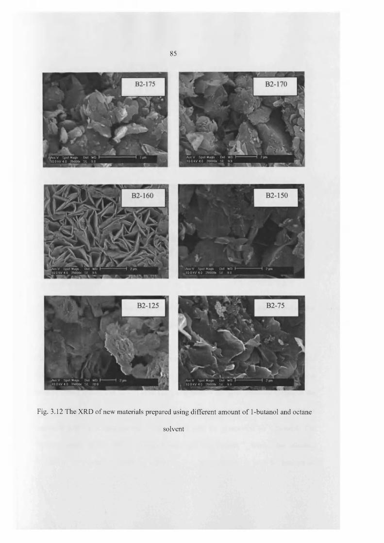
85
Fig. 3.12 The XRD of new materials prepared using different amount of 1-butanol and octane
solvent
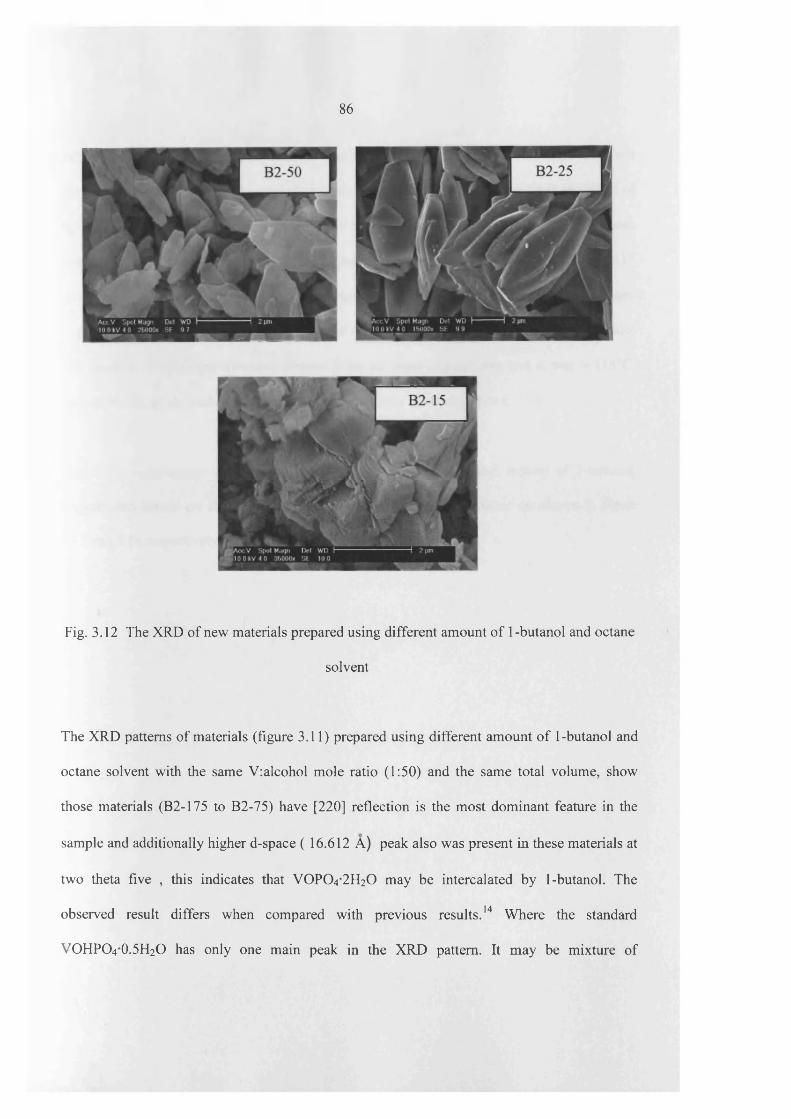
86
Fig. 3.12 The XRD of new materials prepared using different amount of 1 -butanol and octane
solvent
The XRD patterns of materials (figure 3.11) prepared using different amount o f 1-butanol and
octane solvent with the same V:alcohol mole ratio (1:50) and the same total volume, show
those materials (B2-175 to B2-75) have [220] reflection is the most dominant feature in the
sample and additionally higher d-space ( 16.612 A) peak also was present in these materials at
two theta five , this indicates that VOPO4 2 H2O may be intercalated by 1-butanol. The
observed result differs when compared with previous results. 14 Where the standard
VOHPO4 O.5 H2O has only one main peak in the XRD pattern. It may be mixture of

87
VOHPO4 O.5 H2O and VOPO4 intercalates. Furthermore, SEM (figure 3.12) o f these materials
did not show any well defined morphology which is platelet or rosette. The XRD and SEM of
B2-50 and B2-25 indicate that materials have platelet morphology but the size of these
platelets is different; where platelets o f B2-25 are bigger than B2-50 plates. The XRD of B2-15
shows that material has V0 (H2P0 4 ) 2 as the major phase. Therefore, VOHPO4 O.5 H2O phase
switching to VO(H2PC>4)2 phase were obtained by changing the alcohol:octane volume ratio.
The reaction temperature was also measured for all these experiments and it was =118°C.
Therefore, the alcohol:alkane volume ratio is a key factor for these effects.
The above experiments were repeated using 1-octanol as the alcohol instead o f 1-butanol.
Experiments details are shown in Table 3.5. The XRD and SEM of these are shown in figure
3.13 and 3.14 respectively.

88
Table 3.5 Experimental details o f material prepared using different amount of 1-octanol and
octane solvent with VOPO4 .2 H2O (1 g)
Materialname
Mass of VOPO4 .2 H2O
(g)
V:OH mole ratio
1 -Octanol(ml) Octane (ml)
01-175 1 1:175 175 0
01-160 1 1:160 160 15
01-150 1 1:150 150 25
01-135 1 1:135 135 40
01-125 1 1:125 125 50
0 1 - 1 0 0 1 1 : 1 0 0 1 0 0 75
01-75 1 1:75 75 1 0 0
01-50 1 1:50 50 125
01-40 1 1:40 40 135
01-15 1 1:15 15 160
0 1 - 0 1 - 0 175

89
J0 (ooi)V
(101) J 002) O _ M -
01 - 0
/ VQ(101) O O(002)A _ A_ >A /V 0 1 - 1 5
(ijo)A
□ o <1n2)D (022P
T T , T ° T
(230)
□A „ _
(141)□ 01 - 4 0
□A A PJ? P □ 0 1 - 5 0
□ J ? P/P □ □ 0 1 - 7 5
□A A A D A □ □ 0 1 - 1 0 0i !■ ^i ID
I!■ J
i ■£ |
! i\
I i "I 01 -1 2 5
(110) <°°1> ■ (220) T (112)(201)h □ ■ 01 -1 3 5
(001)■
2̂20? (101) (200) (121) g? ■ ■ A 0 1 - 1 5 0
*—(220)
- A . . .1 .01 -1 6 0
(220)- .
0 1 - 1 7 5
1 1 I20 40 60
2 theta(degrees)
Fig. 3.13 The XRD o f new materials prepared using different amount o f 1-octanol and octane
solvent. Key ■ = VOHPO4.0.5H2O; □ = V 0(H 2P 0 4)2 ; V 0 P 0 4 .2H2Q = O
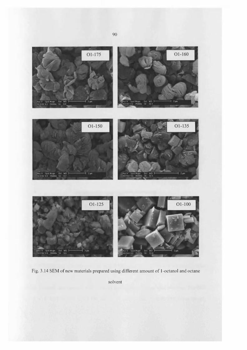
90
Fig. 3.14 SEM of new materials prepared using different amount of 1-octanol and octane
solvent
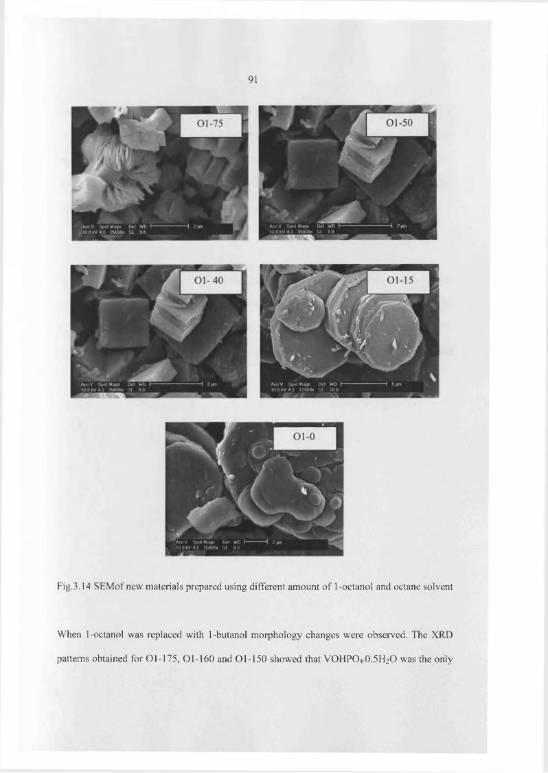
91
Fig.3.14 SEMof new materials prepared using different amount of 1-octanol and octane solvent
When 1-octanol was replaced with 1-butanol morphology changes were observed. The XRD
patterns obtained for 01-175, 01-160 and 01-150 showed that VOHPO4 O.5 H2O was the only
92
phase (figure 3.13). SEM of these materials in figure 3.14 show that all preparations led to a
mixture o f platelet and rosette morphology. The XRD patterns of the materials, 01-135 and
01-125 in figure 3.13, show a mixture o f VOHPO4 O.5 H2O and V0 (H2P0 4 )2 . Materials 01 -
100 to 01-40 have characteristic o f V O ^ P O ^ , by XRD. For all these experiments, the
V:alcohol mole ratio and alcohol: alkane volume ratios were different.
Therefore, the next experiments were carried out with keeping the same V: alcohol mole ratio
while changing alcohol: alkane volume ratio. Experiments details are shown in Table 3.6. The
XRD and SEM of new materials prepared using different amount o f 1-octanol (175, 160. 150,
135, 125, 115, 100, 75, 50, 40, 15 and 0 ml) and octane solvent are shown in figure 3.15 and
3.16 respectively.
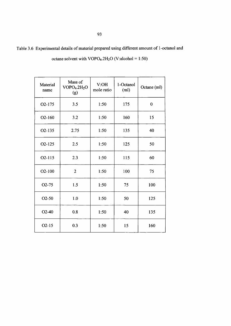
93
Table 3.6 Experimental details o f material prepared using different amount o f 1-octanol and
octane solvent with VOPO4 .2 H2O (V:alcohol = 1:50)
Materialname
Mass of V 0 P 0 4 .2H20
(g)
V:OH mole ratio
1-Octanol(ml) Octane (ml)
02-175 3.5 1:50 175 0
02-160 3.2 1:50 160 15
02-135 2.75 1:50 135 40
02-125 2.5 1:50 125 50
02-115 2.3 1:50 115 60
0 2 - 1 0 0 2 1:50 1 0 0 75
02-75 1.5 1:50 75 1 0 0
02-50 1 .0 1:50 50 125
02-40 0 .8 1:50 40 135
02-15 0.3 1:50 15 160

94
(O O lP j
J \
(002)
o 0 2 -1 5(110)□
y\
(0 0 2 ) ( i2 lV 1̂ m (022)(130)
□ □ □□J □ □ (230)
□(141)
□ 0 2 -4 0
□A □
A□ 0 2 -5 0
(001)■ (101) (200) (121)201) (̂ |0)■ ■ ■ a _ 0 2 -7 5
■ * ■ m " 02 -100
■ ■ ■ A 02-115
■ 02-125
■ ■ " ■ _ " .02 -135
■ 02-160
■___ A _
02-175
1 1— ■ 1 ■20 40
2 theta (degrees)60
Fig. 3.15 The XRD o f new materials prepared using different amount o f 1-octanol and octane
solvent. Key ■ = VOHPO4.0.5H2O; □ = VO(H2P 04)2 ; V 0 P 0 4 .2H2Q = O
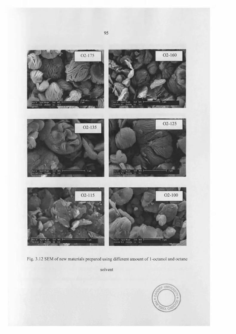
02-175
AccV Spot M.tqri Dot WD I— 10 0 ItV 4 0 3b000» S t 9 8 i lHO
Fig. 3.12 SEM of new materials prepared using different amount of 1-octanol and octane
solvent
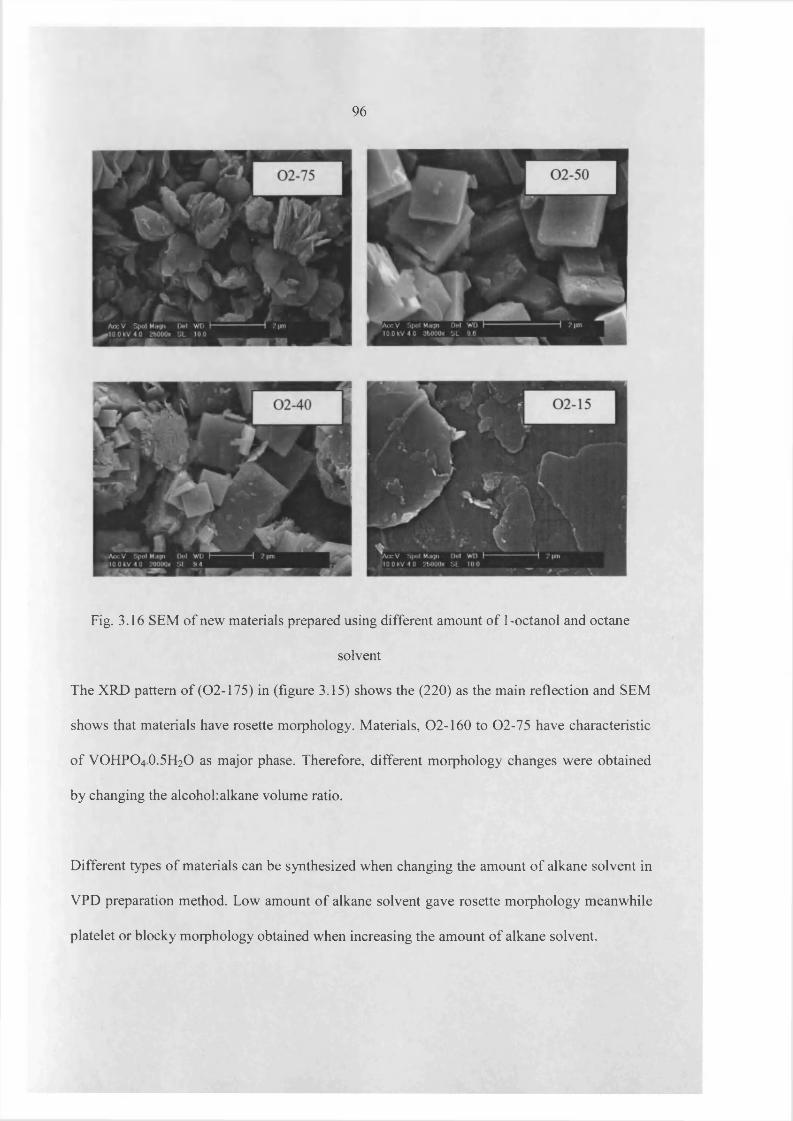
96
Fig. 3.16 SEM of new materials prepared using different amount of 1-octanol and octane
solvent
The XRD pattern of (02-175) in (figure 3.15) shows the (220) as the main reflection and SEM
shows that materials have rosette morphology. Materials, 02-160 to 02-75 have characteristic
o f VOHPO4 O.5 H2O as major phase. Therefore, different morphology changes were obtained
by changing the alcohol:alkane volume ratio.
Different types of materials can be synthesized when changing the amount o f alkane solvent in
VPD preparation method. Low amount o f alkane solvent gave rosette morphology meanwhile
platelet or blocky morphology obtained when increasing the amount of alkane solvent.

97
3.4 Catalyst testing and characterization
3.4.1 Characterization of catalyst
Characterisation o f catalysts after catalyst testing were carried out, precursor was prepared by
reacting o f VOPO4.2 H2O with 1-butanol and differing amount o f octane solvent
(2 0 0 ) (0 4 2 ) B-400
(2 0 0 ) (0 4 2 ) (0 2 0 ) B-100
(0 4 2 )iu l * f H i V ...
(200)
(021) (002)
(020)
(232) (0 6 3 )
(0 4 2 )
(200)
(021) (002)
(020)
(232) (0 6 3 )
—r~20
B-25
B-0
~r~40
2 theta (degrees)60
Fig. 3.17 The XRD patterns o f final catalysts
98
The XRD patterns o f the catalysts derived from the new preparation route using octane as a co
solvent are shown in figure 3.17. Catalysts obtained from the B-0 and B-25 material gave
similar patterns, with all the peaks indexed to (VO)2P2 0 7 . But, crystallinity o f these final
catalysts and intensities o f these peaks are different. According to the literature, (200) plane is
more active for «-butane oxidation in the final catalyst and (200) reflection is considerably
broadened due to a combination o f several overlapping peaks (200, 102, 040) with very similar
plane spacing (0.386, 0.406 and 0.414 nm respectively). The fact that no characteristic lines
from any VOPO4 phases are present in figure 3.17 suggests that such phases are either
completely absent or are present at levels below the detection level of the XRD technique.
XRD patterns o f the final catalyst prepared from the B-100 material suggest that it is poorly
crystallized and small number o f peaks can be assigned to (V0 )2P2 0 7 . Catalyst obtained from
the B- 400 sample gave different patterns than B-0 and B-25 material, but intensity o f (200)
plane is very small in the B-400 catalyst.
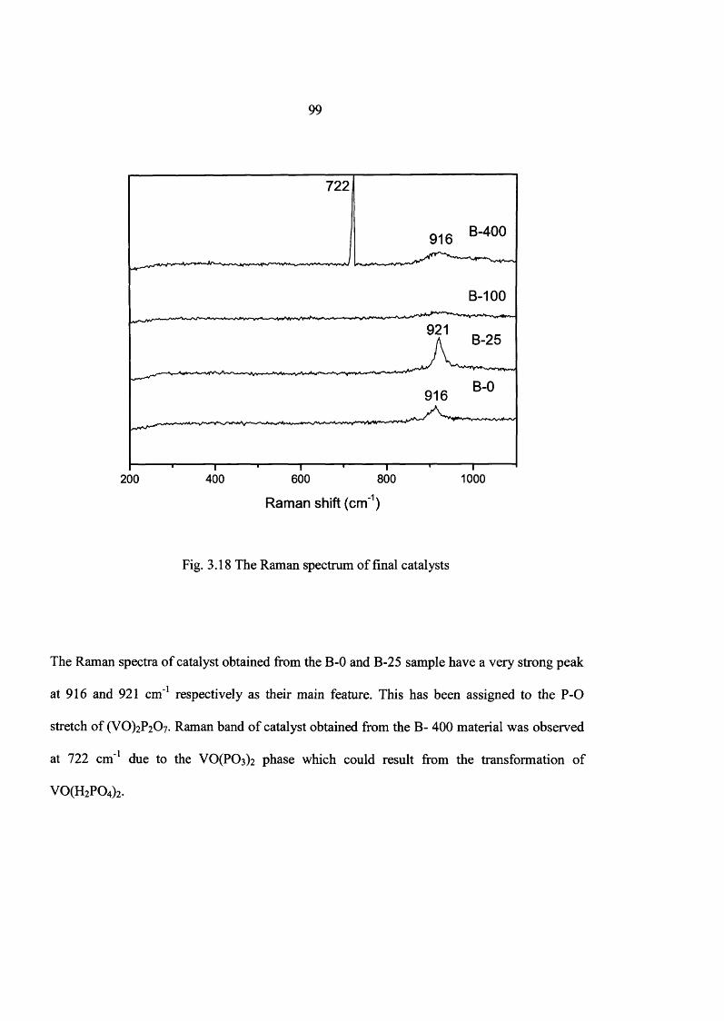
99
722
B-400916
B-100
921B-25
B-0916
200 400 600 800 1000
Raman shift (cm1)
Fig. 3.18 The Raman spectrum of final catalysts
The Raman spectra o f catalyst obtained from the B-0 and B-25 sample have a very strong peak
at 916 and 921 cm'1 respectively as their main feature. This has been assigned to the P-O
stretch o f (VO)2P2(>7. Raman band o f catalyst obtained from the B- 400 material was observed
at 722 cm'1 due to the V0 (P0 3 ) 2 phase which could result from the transformation o f
V0(H 2P 0 4)2.
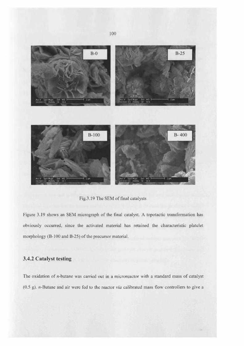
100
Fig.3.19 The SEM of final catalysts
Figure 3.19 shows an SEM micrograph of the final catalyst. A topotactic transformation has
obviously occurred, since the activated material has retained the characteristic platelet
morphology (B-100 and B-25) of the precursor material.
3.4.2 Catalyst testing
The oxidation of /2-butane was carried out in a microreactor with a standard mass o f catalyst
(0.5 g). «-Butane and air were fed to the reactor via calibrated mass flow controllers to give a

101
feedstock composition o f 1.5% n-butane in air. The products were then fed via heated lines to
an on-line gas chromatograph for analysis. The reactor comprised a stainless steel tube with the
catalyst held in place by plugs o f quartz wool. A thermocouple was located in the centre o f the
catalyst bed and temperature control was typically ±1°C. Carbon mass balances o f > 97% were
typically observed. Catalyst samples were heated in situ (1.5% «-butane in air) at 400°C by
heating the sample from room temperature at a rate o f 3°C/min.
3.4.2.1 Evaluation of VPO materials as catalysts for butane oxidation
The importance of vanadium phosphates as catalysts for alkane activation, four materials (B-0,
B-25, B-100 and B-400) were tested for the selective oxidation o f butane and the results are
summarized in Table 3.7.
The catalyst, B-0 and B-25 prepared by in situ activation exhibit the best performance among
the tested catalysts that the butane oxidation o f the B-0 and B-25 materials produced a maleic
anhydride selectivity o f 50% at a butane conversion of 60 and 70% respectively, whereas the
B-100 material showed the same selectivity (50%) o f B-0 and B-25 material but low
conversion. Therefore, VOHPO4.O.5 H2O is the best preferred catalyst precursor for butane
oxidation. Furthermore, VOHPO4.O.5 H2O is the preferred catalyst precursor for commercial
catalyst.1,5,26 The catalyst, B-400 exhibits low selectivity to maleic anhydride.
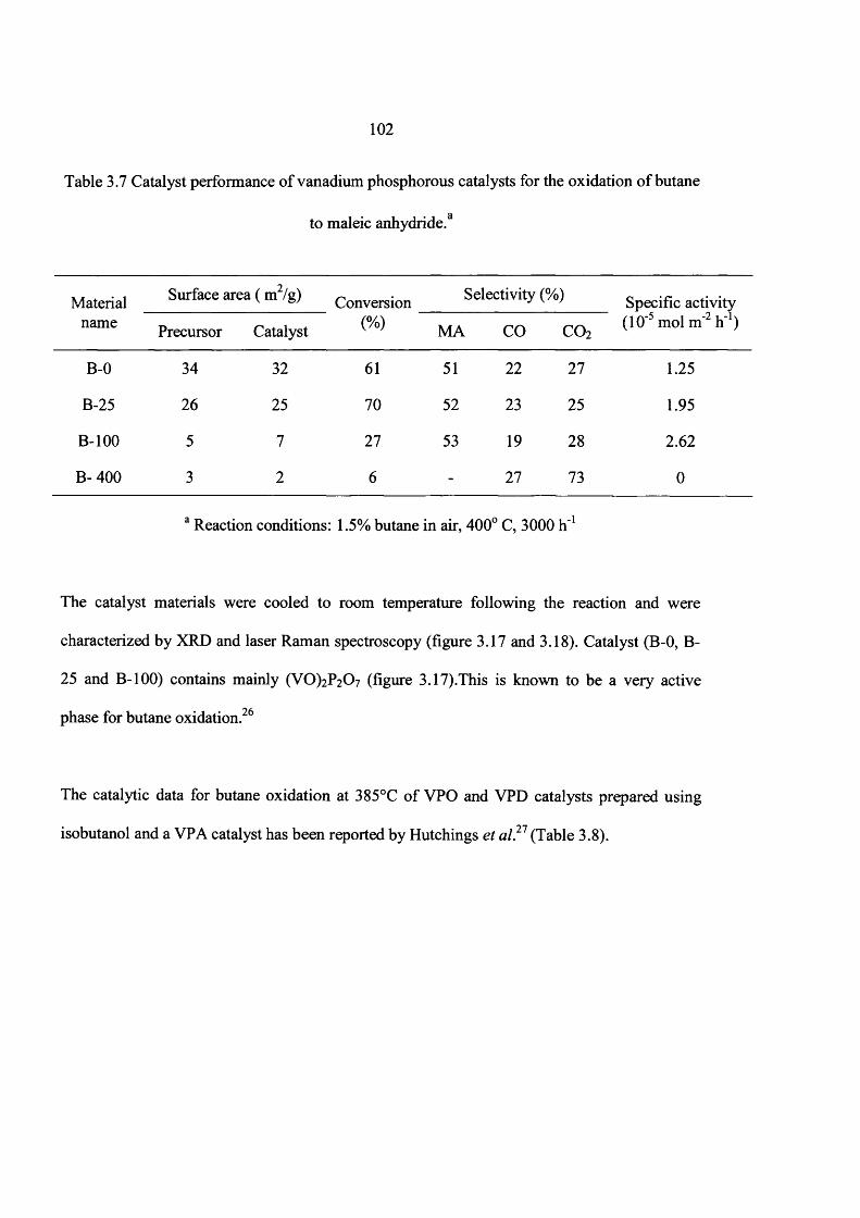
102
Table 3.7 Catalyst performance of vanadium phosphorous catalysts for the oxidation o f butane
to maleic anhydride.3
Materialname
Surface area ( m2/g) Conversion Selectivity (%) Specific activity (10‘5 mol m'2 h’1)Precursor Catalyst (%) MA CO co2
B-0 34 32 61 51 22 27 1.25
B-25 26 25 70 52 23 25 1.95
B-100 5 7 27 53 19 28 2.62
B- 400 3 2 6 - 27 73 0
a Reaction conditions: 1.5% butane in air, 400° C, 3000 h'1
The catalyst materials were cooled to room temperature following the reaction and were
characterized by XRD and laser Raman spectroscopy (figure 3.17 and 3.18). Catalyst (B-0, B-
25 and B-100) contains mainly (VO)2P2 0 7 (figure 3.17).This is known to be a very active
phase for butane oxidation.26
The catalytic data for butane oxidation at 385°C o f VPO and VPD catalysts prepared using
isobutanol and a VP A catalyst has been reported by Hutchings et al.27 (Table 3.8).
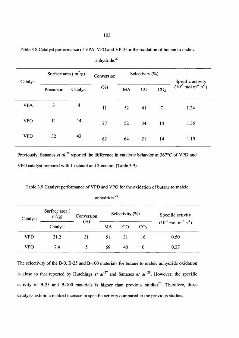
103
Table 3.8 Catalyst performance o f VP A, VPO and VPD for the oxidation o f butane to maleic
anhydride.27
Catalyst
Surface area ( m /g) Conversion Selectivity (%)
Specific activity
Precursor Catalyst (%) MA CO co2 (10'5 mol m‘2 h 1)
VPA 3 4 11 52 41 7 1.24
VPO 11 14 27 52 34 14 1.35
VPD 32 43 62 64 21 14 1.19
Previously, Sananes et al. reported the difference in catalytic behavior at 367°C o f VPD and
VPO catalyst prepared with 1-octanol and 2-octanol (Table 3.9).
Table 3.9 Catalyst performance o f VPD and VPO for the oxidation o f butane to maleic
98anhydride.
Catalyst
Surface area ( m2/g) Conversion
(0/\Selectivity (%) Specific activity
(10’5 mol m'2 h'1)Catalyst
\'VMA CO C 02
VPD 31.2 31 51 31 16 0.50
VPO 7.4 5 59 40 0 0.27
The selectivity o f the B-0, B-25 and B-100 materials for butane to maleic anhydride oxidation
is close to that reported by Hutchings et al?1 and Sananes et al 28. However, the specific
activity o f B-25 and B-100 materials is higher than previous studies27. Therefore, these
catalysts exhibit a marked increase in specific activity compared to the previous studies.

104
3.5 Discussion
The alcohol:alkane volume ratio is a key factor for these morphology changes. Firstly, two
scenarios were investigated. The first one is that VOPO4.2 H2O may react with alkane, and then
reduced with the alcohol to platelet, rosette or blocky morphology (figure 3.20). The second
possibility is VOPO4.2 H2O may be initially reduced by the alcohol (1-butanol or 1-octanol) to
form VOHPO4 O.5 H2O with a rosette structure then the alkane may switch the morphology of
VOHPO4.O.5 H2O to platelet or blocky (figure 3.21).
(001)
(200)( 101) (002)
20 40 60
2 theta (degrees)
Fig. 3.20 VOPO4.2 H2O was reacted with octane and alcohol. Key D = 0 C1-VOPO4

105
To investigate the first scenario, VOPO4.2 H2O (lg, A) was reacted with octane (50 ml) to form
material (B) (figure 3.20). This was then reacted with 1-butanol (25 ml) to form material (C). B
was assigned to 0ti-VOPO4 (marked - D). But the XRD o f (C) was different from (B) that peak
positions of (C) shifted from corresponding peak positions of (B) [marked in numbers] because
the alcohol may be intercalated between the VOPO4 layers. This indicates that refluxing in
alkane dehydrates VOPO4 2 H2O to tti-V 0P04 which can not react further.
For the investigation of the second possibility, VOHPO4 O.5 H2O (lg) was reacted with octane
(50 ml) as shown in figure 3.21 because VOHPO4 O.5 H2O with a rosette morphology forms if
VOPO4.2 H2O reacts with 1-butanol.
220
001
20 40 60
2 theta degrees
Fig. 3.21 VPD (lg) was reacted with octane (50 ml)
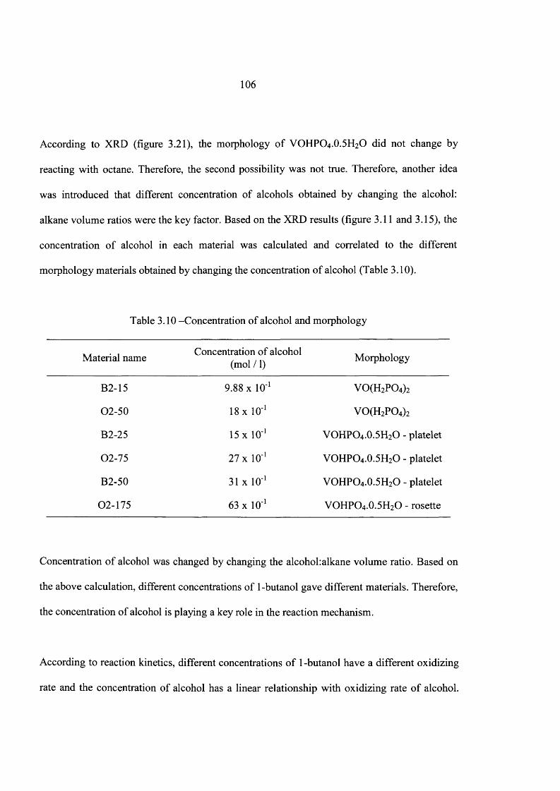
106
According to XRD (figure 3.21), the morphology o f VOHPO4 .O.5 H2O did not change by
reacting with octane. Therefore, the second possibility was not true. Therefore, another idea
was introduced that different concentration of alcohols obtained by changing the alcohol:
alkane volume ratios were the key factor. Based on the XRD results (figure 3.11 and 3.15), the
concentration o f alcohol in each material was calculated and correlated to the different
morphology materials obtained by changing the concentration o f alcohol (Table 3.10).
Table 3.10 -Concentration of alcohol and morphology
Material name Concentration of alcohol (mol / 1)
Morphology
B2-15 9.88 X 10' 1 VO(H2P 0 4) 2
02-50 18 x 1 0 1 V 0(H 2P 0 4) 2
B2-25 15 x 10' 1 VOHPO4 .0.5H2O - platelet
02-75 27 x 10‘‘ VOHPO4 .0.5H2O - platelet
B2-50 31 x 10' 1 VOHPO4 .0.5H2O - platelet
02-175 63 x 10' 1 VOHPO4 .0.5H2O - rosette
Concentration o f alcohol was changed by changing the alcohol:alkane volume ratio. Based on
the above calculation, different concentrations of 1-butanol gave different materials. Therefore,
the concentration of alcohol is playing a key role in the reaction mechanism.
According to reaction kinetics, different concentrations o f 1 -butanol have a different oxidizing
rate and the concentration of alcohol has a linear relationship with oxidizing rate o f alcohol.

107
Furthermore, the reaction rate between 1-butanol and VOPO4 .2 H2O will be changed with
respect to the different oxidizing rate o f 1-butanol.
It was reported in the literature14,29 that V0 (H2P0 4 ) 2 can be formed from VOPO4 .2 H2O whilst
the ratio of V to P is changing from 1:1 to 1:>2. This suggests that VOPO4 .2 H2O dissociates in
the alcohol to give “V5+” and “P” species in the solution as it dissolves. To form
VOHPO4 .O.5 H2O and V 0(H 2P 04) from V 0 P 0 4 .2H20 the V5+ must be reduced to to V4+ by the
alcohol. In the literature it has been shown that in order for VOHPO4 .O.5 H2O to be formed the
V2O5 + H3PO4 the initial step is reduction of V5+ to V4+ shows it goes via V4O9 and a V4+
alkoxide.27,30,31
The literature suggests that VOHPO4 .O.5 H2O and V0 (H2P0 4 ) 2 can be obtained whilst the V: P
ratios kept at 1:1 and 1 :» 1 respectively.8,29 It was found during this study that
VOHPO4 .O.5 H2O was obtained (B2-50 and B2-25) by using a high concentration o f alcohol.
The high concentration o f the alcohol results in a fast reaction rate (between 1-butanol and
VOPO4.2 H2O) and a faster reduction rate (V5+ to V4+). Therefore it can be suggested that
VOHPO4 .O.5 H2O is obtained whilst V4+: P ratio kept at approximately 1:1 due to the fast
reduction o f V5+
It was also found that material VO(H2P0 4 ) 2 was obtained (B2-15 and 02-50) by using a low
concentration of alcohol. The low concentration o f alcohol results in a decreased reaction rate
(between 1-butanol and VOPO4.2 H2O) and a slower reduction rate (V5+ to V4+). The slower
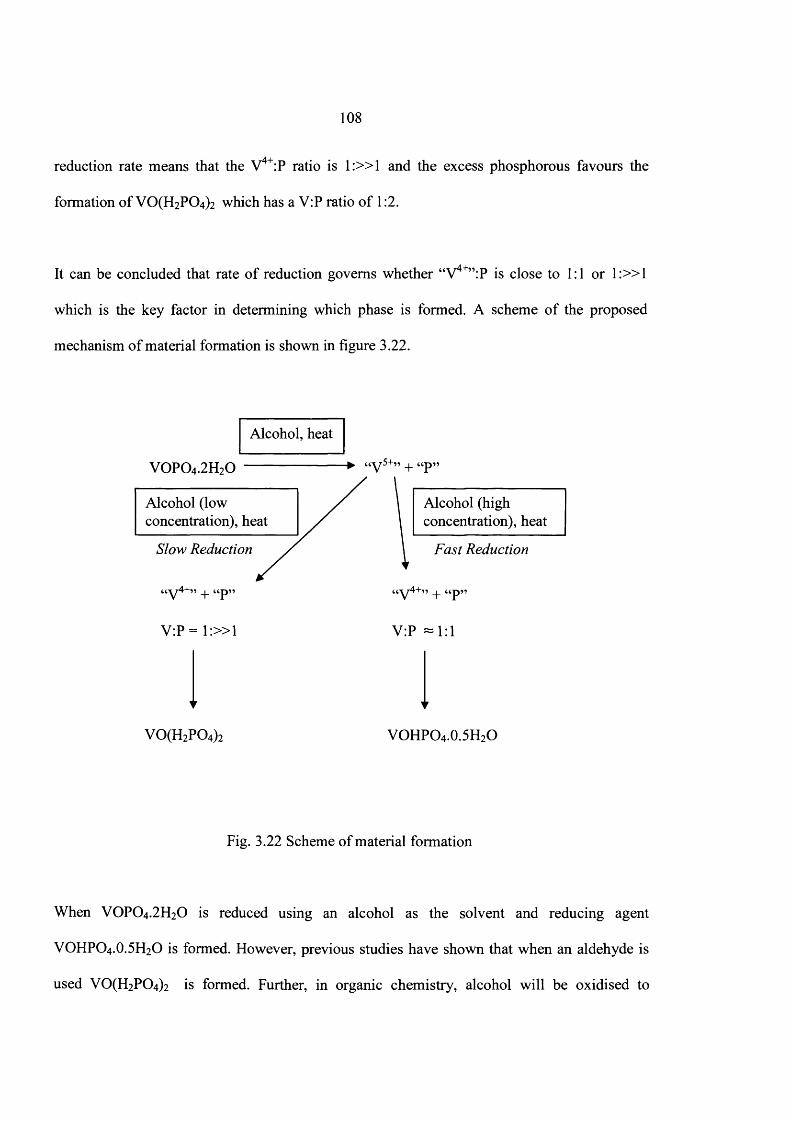
108
reduction rate means that the V4+:P ratio is 1 :» 1 and the excess phosphorous favours the
formation of VO(H2P 0 4) 2 which has a V:P ratio o f 1:2.
It can be concluded that rate o f reduction governs whether “V4+”:P is close to 1:1 or 1 :» 1
which is the key factor in determining which phase is formed. A scheme o f the proposed
mechanism o f material formation is shown in figure 3.22.
Alcohol, heat
V 0 P 0 4 .2H20 -► “v 5+” + “p
Alcohol (low / Alcohol (highconcentration), heat / concentration), heat
Slow Reduction / \ Fast Reduction
V:P = 1 :» 1
“p”
V:P —1:1
VO(H2P04)2 VOHPO4 .0.5H2O
Fig. 3.22 Scheme of material formation
When V 0 P 0 4 .2H20 is reduced using an alcohol as the solvent and reducing agent
VOHPO4 .0.5H2O is formed. However, previous studies have shown that when an aldehyde is
used V0(H 2P 0 4) 2 is formed. Further, in organic chemistry, alcohol will be oxidised to
109
aldehyde when it participates in reduction reaction while aldehyde will be oxidised to
carboxylic acid when aldehyde participates in the reduction reaction. Furthermore, in organic
chemistry, the rate of the reduction will be faster when alcohol is used when compared to
aldehyde at same reaction conditions because in the case o f alcohol, reactive group o f —O-H
attached directly to the C atom but in the case o f aldehyde, = 0 attached with C atom and the
reactivity o f -O-H is higher than the reactivity of = 0 . Therefore, the aldehyde is not as good a
reducing agent as the corresponding alcohol and so there will be a V4+: P ratio o f 1 :» 1
favouring the formation of V O ^ P O ^ .
Further, a mixture of V O ^ P O ^ and VOHPO4 .O.5 H2O was formed when 15 ml o f 1-butanol
and 160 ml of octane were reacted but there was no reaction when 15 ml o f 1 -octanol and 160
ml o f octane were reacted. With octanol, the concentration was not enough to reduce the
VOPO4 .2 H2O but, in the case of 1-butanol, 15 ml o f 1-butanol and 160 ml o f octane switched
the morphology from VOPO4 .2 H2O to V0 (H2P0 4 ) 2 and VOHPO4 .O.5 H2O, so, this
concentration was enough to reduce the VOPO4 .2 H2O. In organic chemistry, 1-butanol can be
easily oxidized to aldehyde when compared with 1 -octanol at same reaction conditions because
of less (+) inductive effect that alkyl group o f CH3 - (CH2V has higher electron releasing
power than CH3 - ( ( ^ 2)2-, therefore more negative charge will be formed on C atom which is
directly connected with O-H group, so (+) inductive effect o f 1-octanol is higher than 1-
butanol therefore less (+) inductive effect is more favour for oxidation o f alcohol. Therefore,
reducing power o f 1-butanol is higher than the 1-octanol and the rate will be higher than the 1 -
octanol.
110
Therefore, concentration of alcohol can be changed by adding the alkane solvent which is
changing the oxidizing rate o f alcohol and the reaction rate between alcohol and VOPO4 .2 H2O.
Furthermore, high concentration of alcohol gave VOHPO4.O.5 H2O while low concentration of
alcohol gave VO(H2PC>4)2 because o f different rate o f the material formation. Therefore,
different concentration o f alcohols gave different materials.
Although the results show that VOHPO4 .O.5 H2O is formed at high concentrations o f alcohol it
was observed that different morphologies o f VOHPO4 .O.5 H2O were obtained at different
alcohol:alkane ratios (Table 3.10). At higher concentrations o f alcohol an XRD pattern with the
(220) crystal plane as the dominant feature; this is characteristic of VOHPO4 .O.5 H2O, with a
rosette morphology. Whilst at lower concentrations the (001) is the dominant feature in the
XRD pattern indicating VOHPO4.O.5 H2O is formed with a platelet morphology. Therefore, the
concentration o f the alcohol can also affect the morphology o f the precipitated crystals.
Solution-phase synthesis is one of the most important methods to control the morphology of
the materials. Further, the precipitation process is a key method to synthesis materials of
different morphology materials in solution phase. It can be said that the concentration of ions
in solution is a deciding factor for obtaining material o f different morphology in the
precipitation method.
VOPO4. 2H2O is soluble in alcohol but not in alkane, and, V5+ reduction to V4+ takes place in
the alcohol medium only. Because of these two above mentioned factors the amount o f alcohol
in the medium plays a very important role in deciding the concentration o f V4+ ions in the
I l l
solution and hence it affects the supersaturation ratio. Due to the varying degree of
supersaturation ratio from the varied alcohol content in the mixture, we get different
morphologies of VOPO4 .O.5 H2O.
Li et al.32 observed a similar result, but for BaSCL crystals from Ba2+ ions and SC>42‘ ions They
also reported that initial Ba2+ ion and SO42' concentration affects the morphology o f the
resultant BaSCL crystals. For example, a rod-like morphology was obtained for BaSCL when
the initial concentration of the constituent ions were low (0.001 mol/1). When the concentration
was increased (0.005 mol/1) a snow like morphology was obtained whereas at higher
concentration o f the constituent ions a leaf-like morphology (0.02 mol/1) or spherical
morphology were obtained (0.1 mol/1).
In this study the initial amount of VOPO4.2 H2O (1 g) used in the reaction if fully dissolved in
the solvent gives rise to a solution of 0.028 mol/1. From our previous reaction scheme for the
mechanism (figure 3.22) we postulate that the VOPO4.2 H2O dissolves to give a V5+ species
and a phosphorous species and the V5+ is then reduced to V4+ quickly. We can therefore expect
to have a solution with 0.028 mol/1 and a V4+ concentration < 0.028 mol/1, depending on the
rate which is governed by the concentration of alcohol. The values are very similar to the
concentrations investigated by Li et al.32 which show that this is a plausible explanation for the
different morphologies observed. This could also explain the differences observed for primary
and secondary alcohols. Both will have a similar reduction rate so both give VOHPO4 .O.5 H2O,
but the secondary alcohol will react slightly slower due to the inductive effect explaining the
112
differences observed with a rosette for the fastest rate and a platelet morphology for the slightly
slower rate.
In another study, Cano et a lP obtained different morphologies o f 2-(4-isobutylphenyl)
propionic acid when it was crystallized from different solvents, he proposed a chemical
interaction between the solvent and the carboxyl group stops crystal growth in a particular
plane. This is not the case for this study as the solvent mixtures both contain the same
components, however this could explain the differences observed with different solvents such
as primary and secondary alcohols.
From the above discussion, it is clearly evident that the alcohol concentration in the reaction
medium affects the V4+ concentration, and in turn affects the degree of supersaturation. From
literature it is known that varying degree of supersaturation affects the morphology o f the
resultant crystal and hence the alcohol concentration affects the degree of supersaturation and
in turn affects the morphology o f the resultant VOHPO4 .O.5 H2O.
3.6 Conclusions
We have shown that adding an alkane co-solvent to the reaction can change the product
formed. We suggest that this is due to the change in reaction rate o f the V5+ to V4+ reduction
which is the key step in our proposed mechanism to determine the product formed.
A fast reduction led to a V4+:P ratio of approximately 1:1 with VOHPO4 .O.5 H2O as the major
product. A slow rate led to a V4+:P ratio of 1 : » 1 with V 0 (H2P0 4 ) 2 as the major product.

113
Small changes in the rate were shown to have an effect on the VOHPO4.O.5 H2O morphology.
This is thought to be due to a slight change in the supersaturation o f the reactants in solution
which has been show previously to have a large influence on the morphology o f the crystals
formed.
Evaluation of the materials as catalysts for the oxidation o f 72-butane to maleic anhydride
shows that the materials exhibit higher specific activities for 72-butane oxidation than previous
studies.
3.7 References
(1) G. Centi, Catal. Today, 1994, 16.
(2) E. Bordes, Catal. Today, 1987, 1, 499.
(3) J.T. Gleaves, J.R. Ebner and T.C. Knechler, Catal. Rev. Sci. Eng., 1988, 30, 49.
(4) G. Centi, F. Trifiro, G. Busca, J. Ebner and J. Gleaves, Faraday Discuss., 1989, 87,
215.
(5) G.J. Hutchings, Appl. Catal., 1991, 72, 1.
(6) G.J. Hutchings, A. Desmartin Chomel, R. Olier and J.C. Volta, Nature, 1994, 368, 41.
(7) C.J. Kiely, A. Burrows, G.J. Hutchings, K.E. Bere, J.C. Volta, A. Tuel and M. Abon, J.
Chem. Soc., Faraday Disc., 1996,105, 103.
(8) J.W. Johnson, D.C. Johnston, A.J. Jacobson and J.F. Brody, J. Am. Chem. Soc., 1984,
106,8123.
(9) H.S. Horowitz, C.M. Blackstone, A.W. Sleight and G.Teufer, Appl. Catal, 1988, 38,
2 1 1 .
114
(10) E.W. Arnold and S. Sundaresan, Appl. Catal., 1988, 41, 457.
(11) K. Ait-Lachgar, M. Abon and J.C. Volta, J. Catal., 1991,171, 383.
(12) E. A. Lombardo, C.A Sanchez and L.M. Conaglia, Catal Today, 1992,15, 407.
(13) F. Benabdelouahab, J.C. Volta and R. Olier, J. Catal., 1994,148, 334.
(14) I.J. Ellison, G.J. Hutchings, M.T. Sananes and J.C. Volta, J. Chem. Soc., Chem.
Commun., 1994, 1093.
(15) V.V. Guliants, J.B. Benziger and S. Sundaresan, Chem. Mater., 1995, 7, 1485.
(16) V.V. Guliants, J.B. Benziger, S. Sundaresan, I.E. Wachs and J.-M. Jehng, Chem.
Mater., 1995, 7, 1485.
(17) V.V. Guliants, J.B. Benziger, S. Sundaresan, N. Yao and I.E. Wachs, Catal Lett., 1995,
32, 379.
(18) V.A. Zazhigalov, J. Haber, J. Storch. L.V. Bogutskaya and I.V. Bacherikova, Appl.
Catal., 1996, 135, 155.
(19) C.J. Kiely, A. Burrows, S. Sajip, G.J. Hutchings, M.T. Sananes, A. Tuel and J.C. Volta,
J. Catal., 1996,162,31.
(20) V.V. Guliants, J.B. Benziger, S. Sundaresan. I.E.Wachs , J.-M. Jehng and J.E. Roberts,
Catal. Today, 1996, 28, 275
(21) N. Yamamoto, T. Okuhara and T. Nakato, J. Mater. Chem, 2001, 11, 1858
(22) Y. Kamiya, S. Ueki, N. Hiyoshi, N. Yamamoto and T. Okuhara, Catal. Today, 2003,
78,281
(23) Y. Kamiya, N. Hiyoshi, N. Ryumon and T. Okuhara, Journal o f Molecular Catalysis
A .'Chemical, 2004, 220, 103

115
(24) Y. Kamiya, N. Yamamoto, H. Imai, S. Komai and T. Okuhara, Microporous and
Mesoporous Materials 2005, 81, 49
(25) N. Yamamoto, N. Hiyoshi and T. Okuhara , Chem. Mater, 2002, 14, 3882
(26) G. J. Hutchings, J. Mater. Chem., 2004, 14, 3385
(27) G. J. Hutchings, C. J. Kiely, M. T. Sananes-Schulz, A. Burrows and J. C. Volta. Catal.
Today, 1998, 40, 273
(28) M. T. Sananes, I. J. Ellision, S. Sajip, A. Burrows, C. J. Kiely, J. C. Volta and G. J.
Hutchings, J. Chem. Soc., Faraday Trans., 1996, 92 (1). 137
(29) Jonathan. K. Bartley, Ph.D thesis, 1999
(30) T. Doi and T. Miyake, Appl. Catal. A, 1997,164, 141
(31) T. Miyake and T. Doi, Appl. Catal., 1995,131, 43
(32) S. Li, J. Xu and G. Luo, J. Crystal Growth 2007, 304, 219
(33) H. Cano, N. Gabas and J. P. Canselier, J. Crystal Growth 2001, 224, 335
116
Chapter 4
Catalyst Preparation Using New Preparation Route
4.1 Introduction
It is generally accepted that the (200) surface in (VO)2P2 0 7 is a key factor for butane
oxidation. 1'3 Many researchers are agreed that (VO)2P2 0 7 plays an important role in the
oxidation o f butane to maleic anhydride.4 These arguments are mainly based on the
observation that only crystalline (VO)2P2 0 7 is obtained after long catalytic reactions.
Bordes et a l 5 also has demonstrated that the (200) plane is selective for the formation o f
MA, while side planes (001), (021) etc. are active for non selective oxidation such as to
CO2 and CO etc.
Previous studies reported that the active catalyst, (VO)2P2 0 7 can be obtained from
VOHPO4 .O.5 H2O precursors, therefore, many researchers have developed new preparation
routes for making catalyst precursors and these precursors when reacted with 1.5%
butane/air at 400°C to obtain selective catalyst.6'9
In this chapter, a new preparation route was developed to synthesize the final catalyst
directly from VOPO4 2 H2O (figure 4.1) and these catalysts were tested for 72-butane
oxidation. This route involves reducing VOPO4 .2 H2O at high temperature to obtain the
final catalyst. Different reducing agents and conditions were analyzed (isobutanol and He
or H2/Ar with different flow rates), among these conditions 50 ml/min, H2/AJ was found to
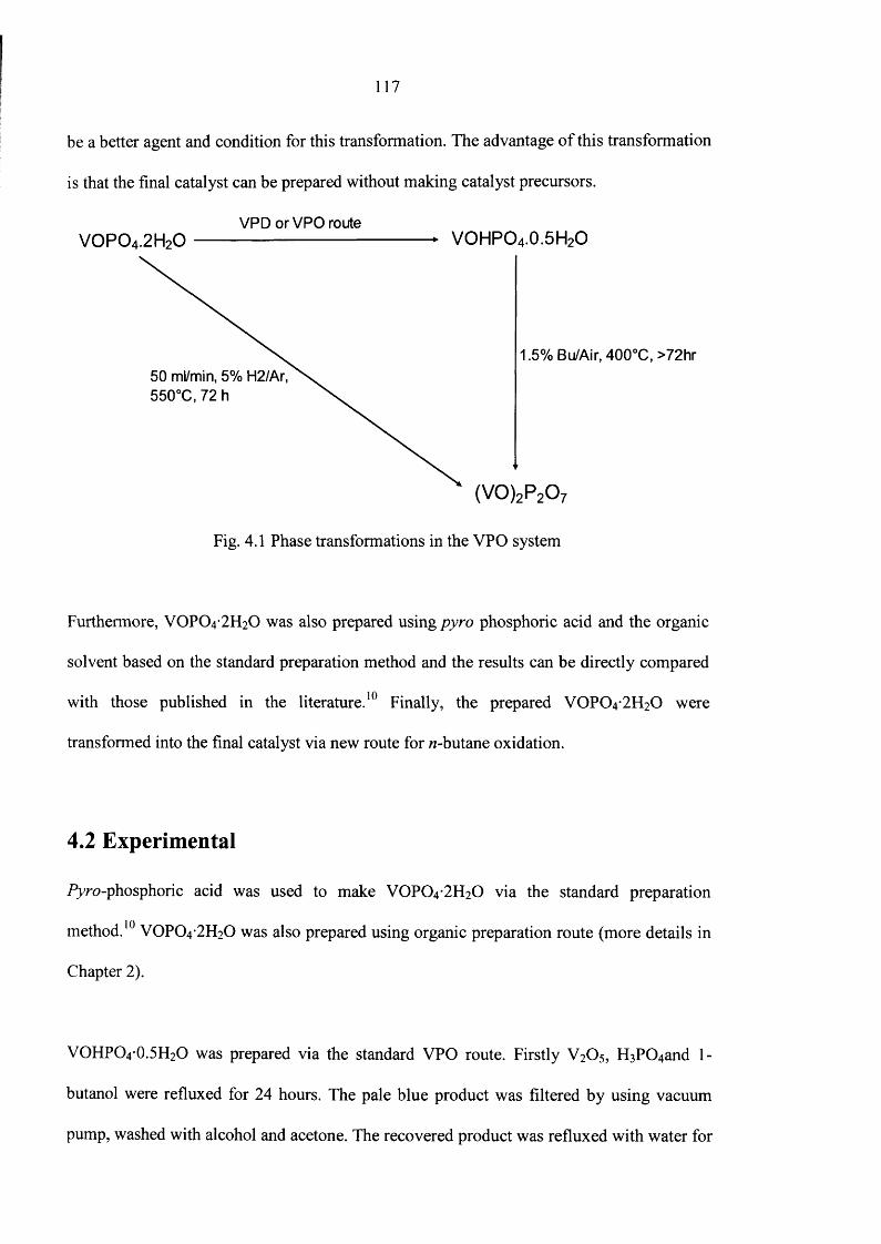
be a better agent and condition for this transformation. The advantage o f this transformation
is that the final catalyst can be prepared without making catalyst precursors.
VPD orVPO routeV0P04.2H20 ------------------------------------- ► VOHPO4.0.5H2O
1.5% Bu/Air, 400°C, >72hr50 ml/min, 5% H2/Ar, 550°C,72 h
Fig. 4.1 Phase transformations in the VPO system
Furthermore, VOPO4 2 H2O was also prepared using pyro phosphoric acid and the organic
solvent based on the standard preparation method and the results can be directly compared
with those published in the literature.10 Finally, the prepared VOPO4 2 FI2O were
transformed into the final catalyst via new route for w-butane oxidation.
4.2 Experimental
Pyro-phosphoric acid was used to make V0 P0 4 *2 H2 0 via the standard preparation
method.10 VOPO4 2 H2O was also prepared using organic preparation route (more details in
Chapter 2).
VOHPO4 O.5H2O was prepared via the standard VPO route. Firstly V2O5, H3P0 4 and 1-
butanol were refluxed for 24 hours. The pale blue product was filtered by using vacuum
pump, washed with alcohol and acetone. The recovered product was refluxed with water for
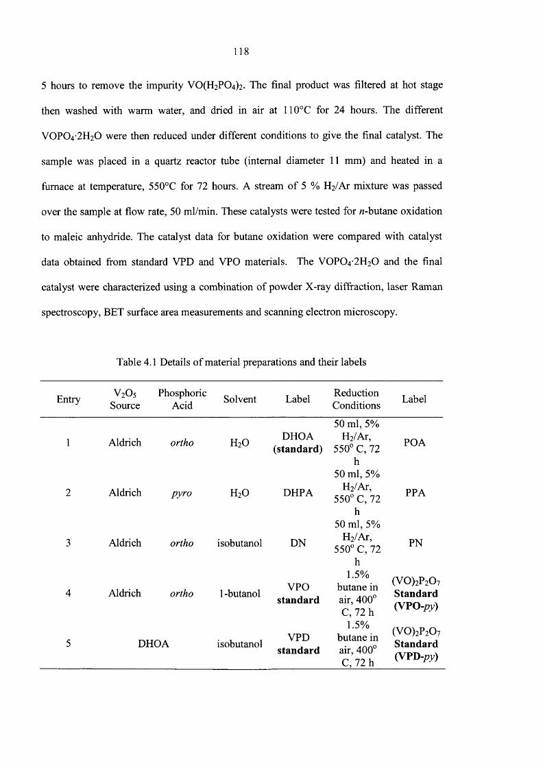
118
5 hours to remove the impurity V 0 (H2P0 4 )2. The final product was filtered at hot stage
then washed with warm water, and dried in air at 110°C for 24 hours. The different
V0 P0 4 -2 H20 were then reduced under different conditions to give the final catalyst. The
sample was placed in a quartz reactor tube (internal diameter 11 mm) and heated in a
furnace at temperature, 550°C for 72 hours. A stream o f 5 % H2/Ar mixture was passed
over the sample at flow rate, 50 ml/min. These catalysts were tested for /2-butane oxidation
to maleic anhydride. The catalyst data for butane oxidation were compared with catalyst
data obtained from standard VPD and VPO materials. The V0 P0 4 -2 H20 and the final
catalyst were characterized using a combination o f powder X-ray diffraction, laser Raman
spectroscopy, BET surface area measurements and scanning electron microscopy.
Table 4.1 Details o f material preparations and their labels
Entry v 2o 5Source
PhosphoricAcid
Solvent Label ReductionConditions
Label
50 ml, 5%
1 Aldrich ortho H20DHOA
(standard)H2/Ar,
550° C, 72 h
50 ml, 5%
POA
2 Aldrich pyro h 2o DHPA H2/Ar, 550° C, 72
h50 ml, 5%
PPA
3 Aldrich ortho isobutanol DN H2/Ar, 550° C, 72
h
PN
4 Aldrich ortho 1 -butanol VPOstandard
1.5% butane in air, 400° C, 72 h
(VO)2P2Ov Standard (VPO -py)
5 DHOA isobutanolVPD
standard
1.5% butane in air, 400° C, 72 h
(V 0 )2P20 7 Standard (VPD -py)
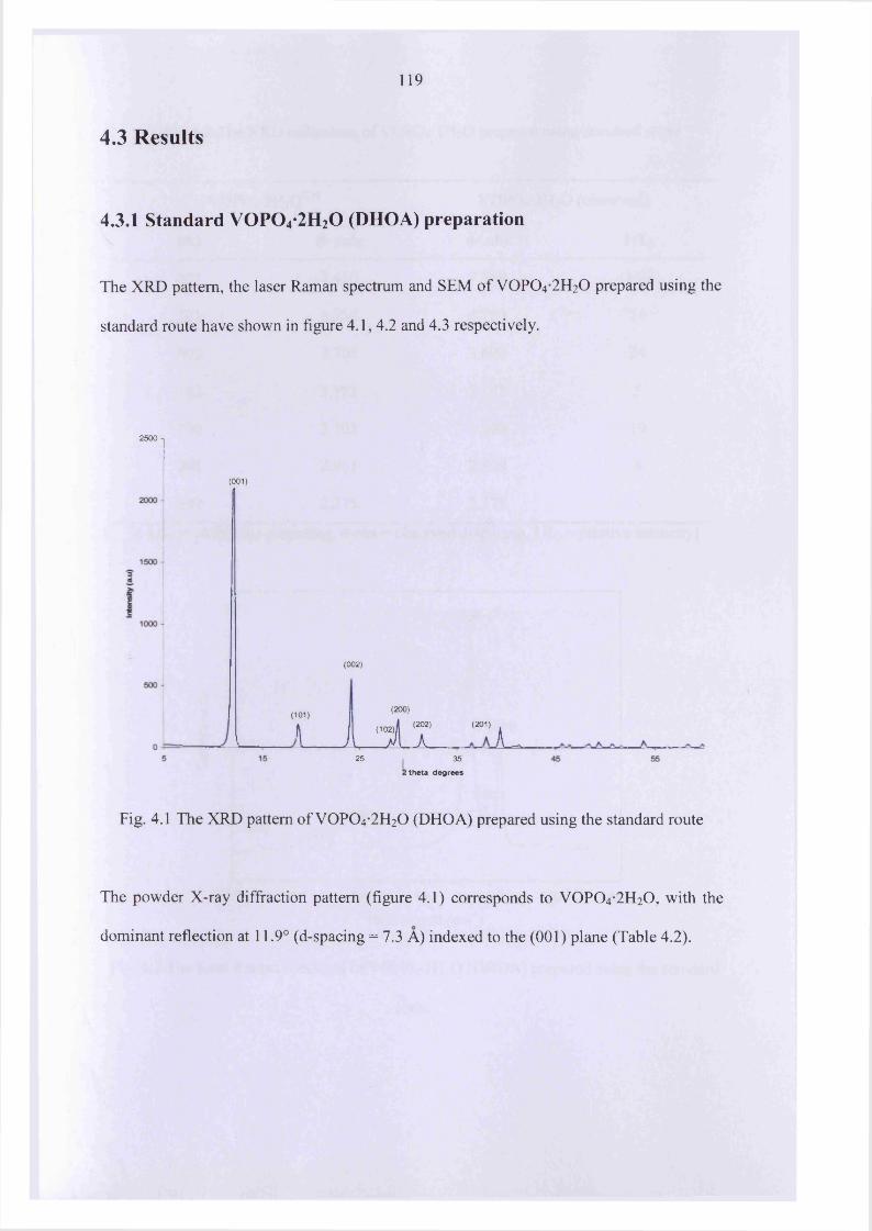
119
4.3 Results
4.3.1 Standard V 0 P 0 4-2H20 (DHOA) preparation
The XRD pattern, the laser Raman spectrum and SEM o f VOPO4 2 H2O prepared using the
standard route have shown in figure 4.1, 4.2 and 4.3 respectively.
2500
(001)
(002)
(101 ) < 7 t I "i 7 "A25 35
! theta degrees
Fig. 4.1 The XRD pattern of VOPO4 2 H2O (DHOA) prepared using the standard route
The powder X-ray diffraction pattern (figure 4.1) corresponds to VOPO4 2 H2O, with the
dominant reflection at 11.9° (d-spacing = 7.3 A) indexed to the (001) plane (Table 4.2).
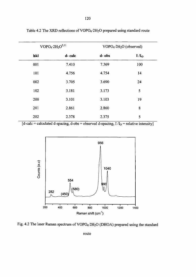
120
Table 4.2 The XRD reflections o f V 0 P 0 4-2H20 prepared using standard route
V 0 P 0 4-2H20 5,11 V O P04-2H20 (observed)
hkl d- calc d- obs I /Io
001 7.410 7.369 100
101 4.756 4.754 14
002 3.705 3.690 24
102 3.181 3.173 5
200 3.101 3.103 19
201 2.861 2.860 8
202 2.378 2.375 5
[d-calc = calculated d-spacing, d-obs = observed d-spacing, I /Io = relative intensity]
956
1040c3OO
554
(580)282 (450;
200 400 600 800 1000 1200 1400
Raman shift (cm'1)
Fig. 4.2 The laser Raman spectrum o f V 0 P 0 4-2H20 (DHOA) prepared using the standard
route
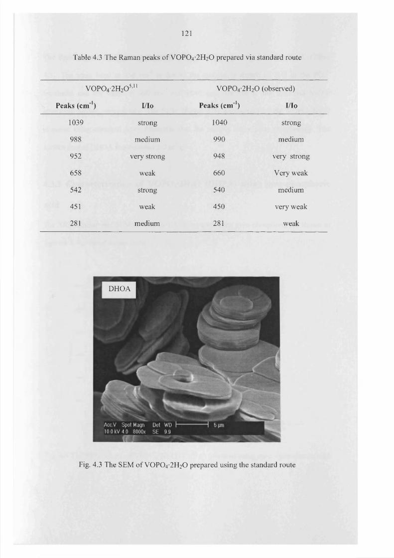
121
Table 4.3 The Raman peaks o f V 0 P0 4 -2 H20 prepared via standard route
< 0 ►a O ■2H20 5,11 V 0 P 0 4 -2H20 (observed)
Peaks (cm 1) I/Io Peaks (c m 1) I/Io
1039 strong 1040 strong
988 medium 990 medium
952 very strong 948 very strong
658 weak 660 Very weak
542 strong 540 medium
451 weak 450 very weak
281 medium 281 weak
DHOA
Fig. 4.3 The SEM o f V 0 P 0 4-2H20 prepared using the standard route
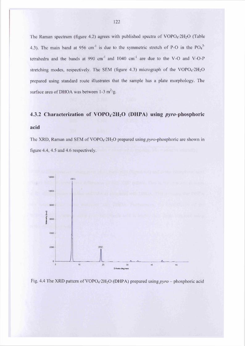
122
The Raman spectrum (figure 4.2) agrees with published spectra o f VOPO4 2 H2O (Table
4.3). The main band at 956 cm' 1 is due to the symmetric stretch o f P-O in the PO43'
tetrahedra and the bands at 990 cm' 1 and 1040 cm' 1 are due to the V -0 and V-O-P
stretching modes, respectively. The SEM (figure 4.3) micrograph o f the VOPO4 2 H2O
prepared using standard route illustrates that the sample has a plate morphology. The
surface area of DHOA was between 1-3 m2/g.
4.3.2 Characterization of V 0 P 0 4-2H20 (DHPA) using /?yro-phosphoric
acid
The XRD, Raman and SEM of VOPO4 2 H2O prepared using pyro-phosphoric are shown in
figure 4.4, 4.5 and 4.6 respectively.
12000(001)
10000
8000
aref 6000
4000
(002)2000
5 15 25 35 45 552 theta degrees
Fig. 4.4 The XRD pattern o f VOPO4 2 H2O (DHPA) prepared using pyro - phosphoric acid

123
Table 4.4 The XRD reflections o f VOPO4 2 H2O prepared using /Tyro-phosphoric acid
V 0P 04 •2H20 5 , 11VOPO4 2 H2O using pyro-
phosphoric acid
hkl d-calc d-obs I/Io
0 0 1 7.410 7.369 1 0 0
1 0 1 4.756 4.754 1
0 0 2 3.705 3.690 17
1 0 2 3.181 3.173 1
2 0 0 3.101 3.103 1
2 0 1 2.861 - -
2 0 2 2.378 2.460 1
[d-calc = calculated d- spacing, d-obs = observed d- spacing, I/Io = relative intensity]
VOPO4 2 H2O prepared using /?yro-phosphoric acid (figure 4.4) and ortho-phosphoric acid
(figure 4.1) displayed some differences in their XRD pattern. That is, the intensity o f some
o f the smaller peaks was less in DHPA as compared with DHOA. This indicates that DHPA
has thinner plates when compared with DHOA. Furthermore, the crystallinity o f the
VOPO4 .2 H2O prepared using /Tyro-phosphoric acid is higher than those prepared using
ortho-phosphoric acid.

124
(950)
3CD(/)C3OO
(1040)(545)
(281). (450 \ (590)
20001000
Raman shift (cm'1)
Fig. 4.5 The laser Raman spectrums o f different VOPO4 2 H2O (DHPA)
The Raman spectrum o f DHPA (figure 4.5) were very close and in agreement with the
published spectra o f VOPO4 2 H2O11 (Table 4.3) and are similar when compared to the
spectrum o f DHOA. This is expected as Raman spectroscopy reveals stretching frequencies
and bending modes between the atoms and as such is a fingerprint technique. Therefore,
any differences observed in the morphology or crystallinity o f the samples would not be
seen using Raman spectroscopy.

125
DHPA
Fig. 4.6 The SEM o fV 0 P 0 4*2H20
The SEM micrograph (figure 4.6) of the VOPO4 2 H2O prepared using the /?yro-phosphoric
9acid has a platelet morphology. The surface area o f DHPA was between 1-3 m /g.
4.3.3 Characterization of V 0 P 0 4*2H20 prepared in organic solvent
The XRD pattern and SEM of VOPO4 2 H2O prepared using organic solvent designated as
DN are shown in Figure 4.7 and 4.8.
VOPO4 2 H2O prepared using organic solvent route has a very different XRD pattern
compared to the standard materials (Table 4.1). It is interesting to note that the [001] and
[200] reflections in figure 4.7 are considerably broadened as compared with standard
VOP04-2H20 .
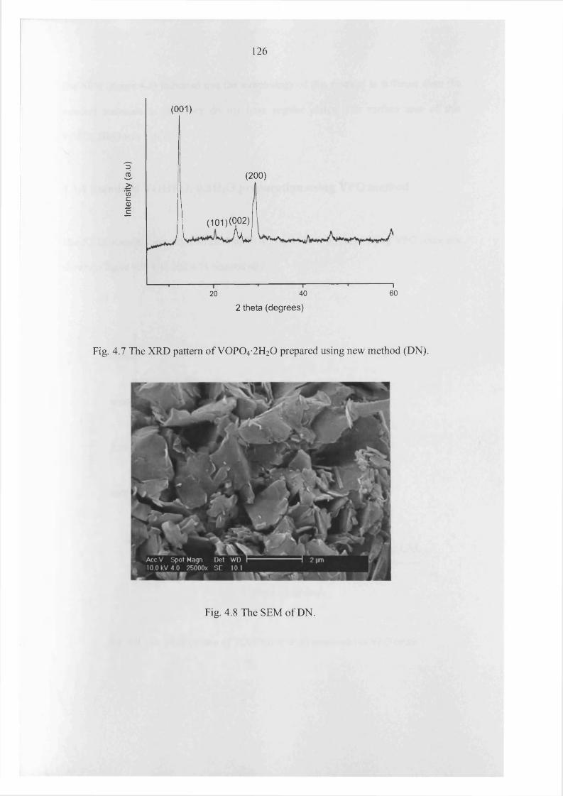
Inte
nsity
(a
.u)
126
(001)
(200)
( 101) (002)
A vJ
” 16020
i40
2 theta (degrees)
Fig. 4.7 The XRD pattern of VOP0 4 -2 H20 prepared using new method (DN).
Fig. 4.8 The SEM o f DN.
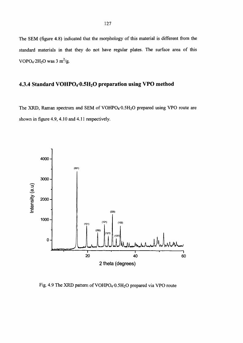
127
The SEM (figure 4.8) indicated that the morphology o f this material is different from the
standard materials in that they do not have regular plates. The surface area o f this
V 0 P 0 4-2H20 was 3 m2/g.
4.3.4 Standard VOHPCVO.Si^O preparation using VPO method
The XRD, Raman spectrum and SEM of VOHPO4 O.5 H2O prepared using VPO route are
shown in figure 4.9, 4.10 and 4.11 respectively.
4000-
(001)
3000-
DCO
&COca>
2000 -
c (220)
1000-(121)
(101)
(200)(121)
(131)
0 -
20 40 60
2 theta (degrees)
Fig. 4.9 The XRD pattern o f VOHPO4 O.5H2O prepared via VPO route
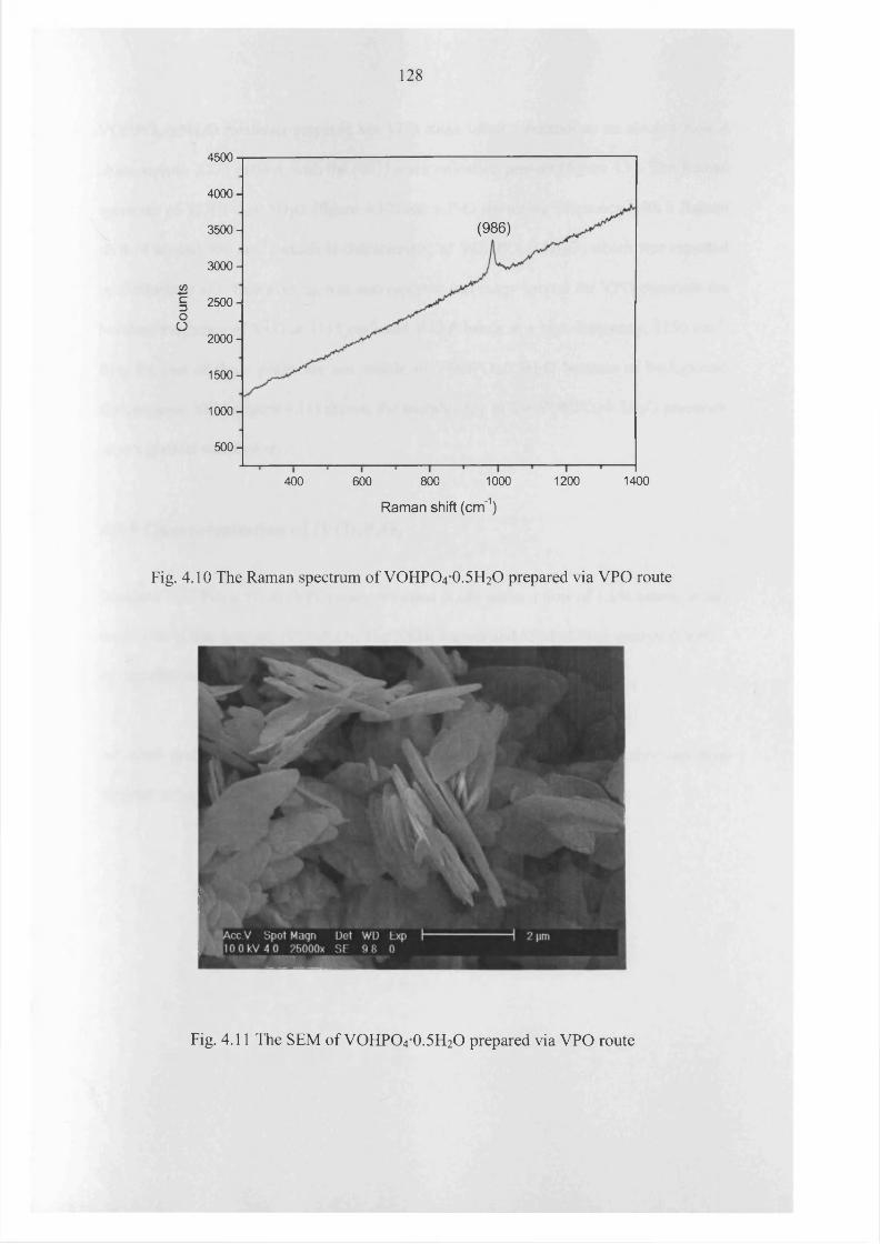
Cou
nts
128
4500
4 0 0 0 -
(986)3 5 0 0 -
3 0 0 0 -
2 5 0 0 -
2000 -
15 0 0 -
1000 -
5 0 0 -
1000 1400400 600 800 1200
Raman shift (cm'1)
Fig. 4.10 The Raman spectrum of VOHPO4 O.5 H2O prepared via VPO route
Fig. 4.11 The SEM of VOHPO4 O.5 H2O prepared via VPO route
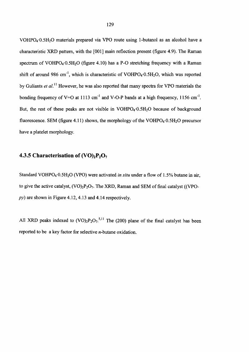
129
VOHPO4 O.5 H2O materials prepared via VPO route using 1-butanol as an alcohol have a
characteristic XRD pattern, with the [001] main reflection present (figure 4.9). The Raman
spectrum o f VOHPO4 O.5 H2O (figure 4.10) has a P-O stretching frequency with a Raman
shift o f around 986 cm'1, which is characteristic o f VOHPO4 O.5 H2O, which was reported
by Guliants et al.u However, he was also reported that many spectra for VPO materials the
bonding frequency o f V = 0 at 1113 cm'1 and V-O-P bands at a high frequency, 1156 cm'1.
But, the rest o f these peaks are not visible in VOHPO4 O.5 H2O because o f background
fluorescence. SEM (figure 4.11) shows, the morphology o f the VOHPO4 O.5 H2O precursor
have a platelet morphology.
4.3.5 Characterisation of (V 0)2P207
Standard VOHPO4 O.5 H2O (VPO) were activated in situ under a flow o f 1.5% butane in air,
to give the active catalyst, (VO)2P207. The XRD, Raman and SEM of final catalyst ((VPO-
p y ) are shown in Figure 4.12,4.13 and 4.14 respectively.
All XRD peaks indexed to (V0 )2P2 0 7 .5,11 The (200) plane o f the final catalyst has been
reported to be a key factor for selective w-butane oxidation.

&V)ca>(063)
c
40 6020
2 theta (degrees)
Fig. 4.12 The XRD patterns o f the o f the (VO)2P2 0 7 (VPO-py).
(928)
(1187)
</>
coO
200 400 1000 1200600 800
Raman shift (cm'1)
Fig. 4.13 Raman spectrum o f the o f the final catalyst (VPO-/?y)
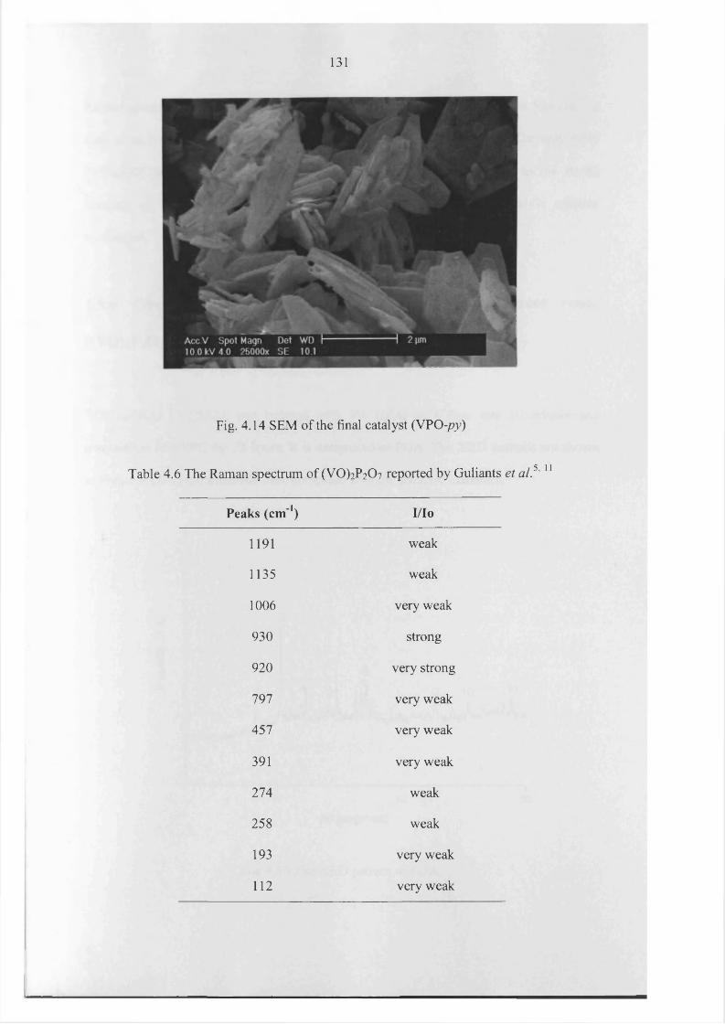
131
Fig. 4.14 SEM of the final catalyst (VPO-py)
Table 4.6 The Raman spectrum of (VO^PzCb reported by Guliants et al.5' 11
Peaks (cm 1) I/Io
1191 weak
1135 weak
1006 very weak
930 strong
920 very strong
797 very weak
457 very weak
391 very weak
274 weak
258 weak
193 very weak
112 very weak
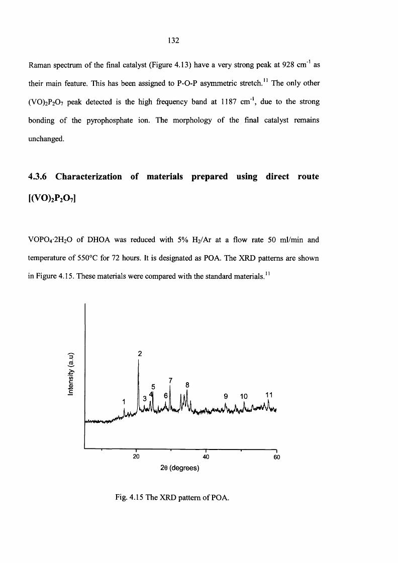
132
Raman spectrum o f the final catalyst (Figure 4.13) have a very strong peak at 928 cm ' 1 as
their main feature. This has been assigned to P-O-P asymmetric stretch. 11 The only other
(VO)2P2C>7 peak detected is the high frequency band at 1187 cm'1, due to the strong
bonding o f the pyrophosphate ion. The morphology o f the final catalyst remains
unchanged.
4.3.6 Characterization of materials prepared using direct route
1(V0)2P20 7]
VOPO4 2 H2O o f DHOA was reduced with 5% H2/Ar at a flow rate 50 ml/min and
temperature o f 550°C for 72 hours. It is designated as POA. The XRD patterns are shown
in Figure 4.15. These materials were compared with the standard materials. 11
DCD
£COcCD■4—>c
20 40 60
20 (degrees)
Fig. 4.15 The XRD pattern o f POA.
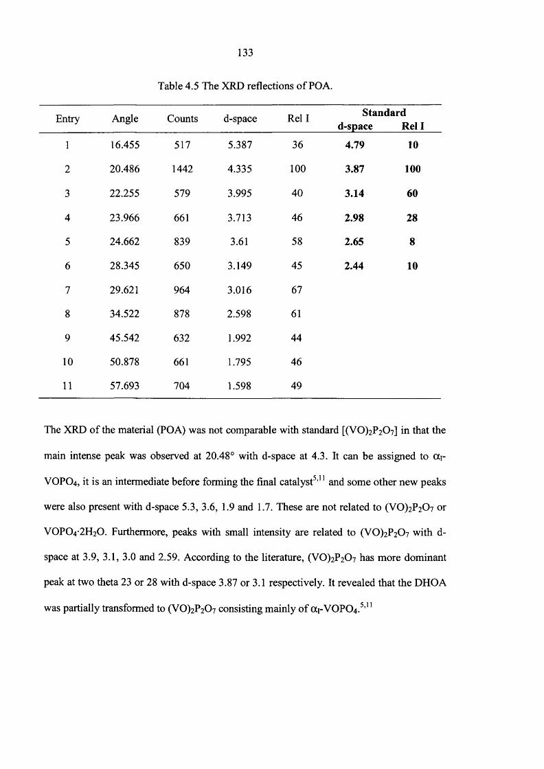
133
Table 4.5 The XRD reflections o f POA.
Entry Angle Counts d-space Rel I Standard d-space Rel I
1 16.455 517 5.387 36 4.79 10
2 20.486 1442 4.335 1 0 0 3.87 100
3 22.255 579 3.995 40 3.14 60
4 23.966 661 3.713 46 2.98 28
5 24.662 839 3.61 58 2.65 8
6 28.345 650 3.149 45 2.44 10
7 29.621 964 3.016 67
8 34.522 878 2.598 61
9 45.542 632 1.992 44
1 0 50.878 661 1.795 46
11 57.693 704 1.598 49
The XRD o f the material (POA) was not comparable with standard [(V0)2P207] in that the
main intense peak was observed at 20.48° with d-space at 4.3. It can be assigned to oci-
VOPO4, it is an intermediate before forming the final catalyst5,11 and some other new peaks
were also present with d-space 5.3, 3.6, 1.9 and 1.7. These are not related to (VO)2P2 0 7 or
VOPO4 2 H2O. Furthermore, peaks with small intensity are related to (VO)2P2 0 7 with d-
space at 3.9, 3.1, 3.0 and 2.59. According to the literature, (V0 )2P2 0 7 has more dominant
peak at two theta 23 or 28 with d-space 3.87 or 3.1 respectively. It revealed that the DHOA
was partially transformed to (VO)2P2 0 7 consisting mainly o f (X1-VOPO4.5,11

134
The laser Raman spectrum o f POA is shown in figure 4.16. SEM o f POA is shown in figure
4.17.
1 3 4 2
Dai,wc3OO
6868 3 6
271 4 7 3
200 400 600 800 12001000 1400
Raman shift (cm'1)
Fig. 4.16 The laser Raman spectrum of (POA)
The laser Raman peaks o f POA (figure 4.16) cannot be assigned to (VO)2P2 0 7 . But two
peaks (271 and 473 cm'1) were related to VOPO4 2 H2O. It confirmed that DHOA was
partially transformed to (VO)2P2 0 7 .
Fig. 4.17 The SEM of the materials prepared using direct route.

135
The SEM o f POA (figure 4.17) was different from the starting materials (figure 4.3). The
SEM of POA revealed that the plates were small when compared with the starting
materials. These results suggested that the materials prepared by this direct route have a
different morphology from their starting materials but final catalyst prepared from
VOHPO4 .O.5 H2O precursors have the same morphology and surface area o f their starting
catalyst precursors. The surface areas o f these materials were the same as the starting
materials (1-3 m2/g)
The VOP0 4 -2 H2 0 o f DHPA was reduced with 5% H2 /Ar at a flow rate o f 50 ml/min and a
temperature o f 550°C for 72 hours. It is designated as PPA. The XRD pattern o f PPA is
shown in figure 4.18. It was compared with standard materials.11
2 5 00-
2000-
1500-
1000-
5 0 0 -
20 40 60
2 theta (degrees)
Fig. 4.18 The XRD pattern PPA.
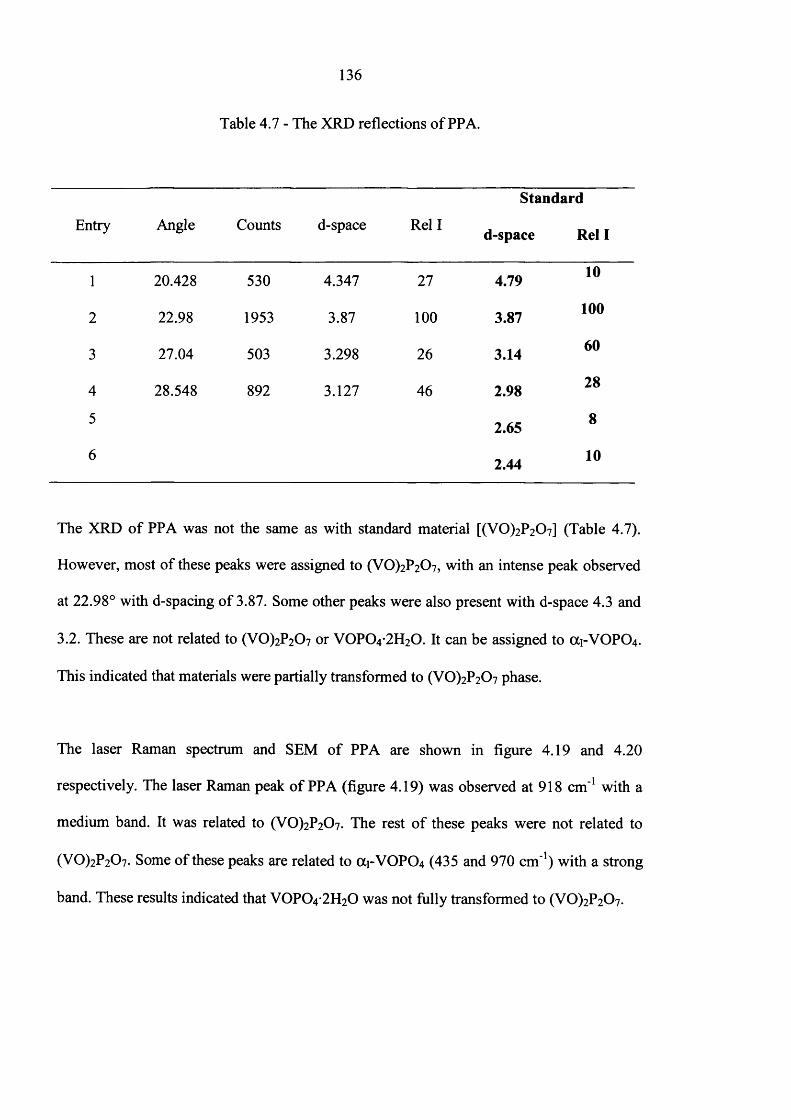
136
Table 4.7 - The XRD reflections o f PPA.
Standard
Entry Angle Counts d-space Rel I d-space Rel I
1 20.428 530 4.347 27 4.79 10
2 22.98 1953 3.87 1 0 0 3.87 100
3 27.04 503 3.298 26 3.14 60
4 28.548 892 3.127 46 2.98 28
5 2.65 8
6 2.44 10
The XRD o f PPA was not the same as with standard material [(VO)2P2C>7] (Table 4.7).
However, most o f these peaks were assigned to (VO)2P2 0 7, with an intense peak observed
at 22.98° with d-spacing o f 3.87. Some other peaks were also present with d-space 4.3 and
3.2. These are not related to (VO)2P2 0 7 or VOPO4 2 H2O. It can be assigned to OC1-VOPO4 .
This indicated that materials were partially transformed to (VO)2P2C>7 phase.
The laser Raman spectrum and SEM o f PPA are shown in figure 4.19 and 4.20
respectively. The laser Raman peak o f PPA (figure 4.19) was observed at 918 cm ' 1 with a
medium band. It was related to (VO)2P2 0 7 . The rest o f these peaks were not related to
(VO)2P2 0 7 . Some o f these peaks are related to ai-V 0 P0 4 (435 and 970 cm'1) with a strong
band. These results indicated that VOPO4 2 H2O was not fully transformed to (VO)2P2 0 7 .

Coun
ts
(a.u
)
137
435970
9181232
702
1400800 1000 1200200 400 600
Raman shift (cm'1)
Fig. 4.19 The laser Raman spectrum of PPA.
Fig. 4.20 The SEM o f PPA.
The SEM of PPA (figure 4.20) indicated that materials were arranged with irregular
fractured plates comparable to DHPA.

138
Furthermore, based on these above results, VOPO4 2 H2O prepared using pyro -phosphoric
or or/Zzo-phosphoric acid was fully or partially transformed to (VO)2P2C>7. However,
intermediate phases were present in these final catalysts [(VO)2P2 0 7 ].
The VOPO4 2 H2O of DN was reduced with 5% H2/Ar at a flow rate 50 ml/min and a
temperature o f 550°C for 72 hrs. It is designated as PN. The XRD pattern o f PN is shown in
figure 4.21. It was compared with standard materials. 11
(042)
DCD
&COcCD
c
20 40 60
20 (degrees)
Fig. 4.21 The XRD pattern o f PN

139
Table 4.8 - The XRD reflections o f PN.
Entry Angle Counts Dspace Rel I
1 28.432 941 3.139 100
The XRD o f PN has only one peak with d-space at 3.1, it can be assigned to (VO)2P2C>7 .
The crystallinity o f these materials was lower as compared with POA and PPA. The surface
areas o f these materials were the same as the surface area o f DN (3 m /g)
tikAccV Spot Magn Det WD I 10.0 kV 4 0 25000X SE 10 7
Fig. 4.22 The SEM of PN.
The morphology of PN was different from DN. PN was arranged with fractured irregular
plates.
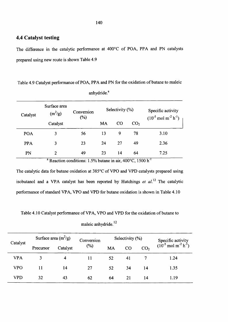
140
4.4 Catalyst testing
The difference in the catalytic performance at 400°C o f POA, PPA and PN catalysts
prepared using new route is shown Table 4.9
Table 4.9 Catalyst performance o f POA, PPA and PN for the oxidation o f butane to maleic
anhydride.3
Catalyst
Surface area
(m2/g) Conversion(%)
Selectivity (%) Specific activity
(10'5 mol m'2 h'1)Catalyst MA CO C 0 2
POA 3 56 13 9 78 3.10
PPA 3 23 24 27 49 2.36
PN 2a •
49 23 14 64 7.251-1
The catalytic data for butane oxidation at 385°C o f VPO and VPD catalysts prepared using
1 0isobutanol and a VPA catalyst has been reported by Hutchings et al. The catalytic
performance o f standard VPA, VPO and VPD for butane oxidation is shown in Table 4.10
Table 4.10 Catalyst performance o f VPA, VPO and VPD for the oxidation o f butane to
maleic anhydride.12
Surface area (m2/g) Conversion Selectivity (%) Specific activityCatalyst . ,m-5 i -2i_-k
Precursor Catalyst ̂ MA CO CO2 m° m
VPA 3 4 11 52 41 7 1.24
VPO 11 14 27 52 34 14 1.35
VPD 32 43 62 64 21 14 1.19
141
1 9Based on the previous studies, catalyst precursors with rosette structure (VPD) have much
higher surface area than VOHPO4 .O.5 H2O precursors prepared by the VPO or VPA route.
The different catalysts have similar specific activities, so the surface area o f the catalyst is
the crucial factor in determining the final activity.
According to the present study (Table 4.9), the catalyst prepared via the direct route did not
yield a higher activity for w-butane oxidation than the catalyst prepared from
VOHPO4 .O.5 H2O precursors.12 Among these present results, catalysts POA, PPA and PN
are less selective for maleic anhydride. However, specific activity o f these catalysts is
higher when compared to the conventional VPO and VPD catalyst.
4.5 Discussion
VOPO4 2 H2O prepared using different phosphoric acids gave different XRD patterns.
During the reaction the V2O5 dissolves in pyro-phosphoric acid very fast upon heating. In
ort/iophosphoric acid, V 2O5 only dissolves after the reaction has reached reflux conditions.
As the V2O5 is not completely dissolved immediately in the or/Zzophosphoric acid
preparation, it is likely that there is a small amount o f V2O5 impurity in the VOPO4 2 H2O
crystals. These impurities can cause defects in the structure, leading to a loss in
crystallinity.10
Commonly, V2O5 dissolves in concentrated acid or alkali solution. In the standard
preparation methods, initially V2O5 is not fully dissolved. Therefore, isobutanol was used as
solvent to increase the solubility o f V2O5 in the organic preparation route while water was
142
used as solvent in the standard preparation method. In the organic preparation route, the
(0 0 1 ) and (2 0 0 ) reflections were considerably broadened when compared with standard
VOPO4 2 H2O, it indicated that VOPO4 2 H2O prepared using organic solvent method gave
smaller crystallites as compared with standard methods.
The prepared catalyst materials via the new route were found to have <i-spacing 3.8 as with
the standard (VO^PzOz but these materials are less selective for w-butane oxidation because
(X1-VOPO4 was formed with these catalyst materials. It has been reported that OC1-VOPO4 is
19not selective for «-butane oxidation. Therefore, the active site o f (VO)2P2 0 7 could be
obstructed by other unselective sites. Hence, these materials exhibited less selectivity for
butane to maleic anhydride oxidation. According to the previous results, the final catalyst
prepared from VOHPO4 .O.5 H2O has the same surface area and morphology as the
VOHPO4 .O.5 H2O precursors. The surface area o f these precursors was high (Table 4.10).
Therefore, these materials are more selective for butane oxidation (50% selectivity and 60%
conversion). The final catalyst prepared from VOPO4 2 H2O via the new route has a lower
surface area, comparable to VOPO4 2 H2O. Therefore, these materials are less selective for
butane oxidation. However, specific activity o f the final catalyst prepared via direct route is
better than the conventional catalyst due to the low surface area.
4.6 Conclusions
Same morphology o f VOPO4 2 H2O was obtained using different phosphoric acid while
differing the size o f the plate. The VOPO4 2 H2O prepared using organic solvent gave
smaller crystallite when compared with standard methods. VOPO4 2 H2O was partially or
fully transformed to (VO)2P2 0 7 using this direct route. The selectivity o f these final
143
catalysts for butane oxidation is less than the conventional catalysts (VPD and VPO).
However, these materials exhibit a marked increases in specific activity compared to both
the VPD and VPO.
4.7 References
(1) F. Trifiro and F. Cavani, Chemtech, 1994, 18
(2) Y. Zhang, R. P. A. Sneeden and J. C. Volta, Catal. Today, 1993 ,16, 39
(3) J. Ziolkowski, E. hordes and P. Courtine, J. Catal, 1994 ,16, 126
(4) J. R. Ebner, M. R. Thompson, Catal. Today, 1993 ,16, 51
(5) E. Bordes, Catal. Today, 1987,1, 499
(6) I. J. Ellison, G. J. Hutchings, M. T. Sananes , J. C. Volta and , J. Chem. Soc., Chem.
Comm, 1994, 1093
(7) C. J. Kiely, A. Burrows, S. Sajip, G. J. Hutchings, M. T. Sananes, A. Tuel and J. C.
V olta ,/. Catal, 1996 ,162, 31
(8) G. J. Hutchings, A. Desmartin- Chomel, O. Oliver, J. C. Volta, Nature, 1994, 348,
41
(9) C. J. Kiely, A. Burrows, G.J. Hutchings, K. E. Bere, J. C. Volta, A. Tuel, M. Abon,
J. Chem. Soc, Faraday Discuss, 1996 ,105, 103
(10) J. W. Johnson, D. C. Johnston, A. J. Jacobson and J. F. Brody, J. Am. Chem. Soc,
1984,106,8123
(11) V .V. Guliants, J.B. Benziger, S. Sundaresan, I. E. Wachs, J. M. Jehng, J. E.
Roberts, Catal. Today, 1996, 28, 275
(12) C. J. Kiely, A. Burrows, G.J. Hutchings, K.E. Bere, J.C. Volta, A. Tuel and M.
A bon,/. Chem. Soc., Faraday Disc., 1996, 105, 103.
144
Chapter 5
Summary and Conclusions
5.1 Control the Morphology of Vanadium Phosphate Catalyst Precursors by
Adding Alkane Solvents
Almost four decades have passed since Bergman and Frisch reported that VPO catalysts
selectively oxidised «-butane to maleic anhydride. During this period, a number o f synthesis
approaches have been reported to control the morphology o f vanadium phosphate catalyst
precursors1,2 because the catalytic properties o f (VO)2P2 0 7 are very dependent on its method o f
3 7preparation and the best catalysts are prepared topotactically via VOHPO4 .O.5 H2O. '
(1) V2O5, phosphoric acid and alcohol were refluxed.
(2) VOPO4 .2 H2O was reduced by various alcohols.
(3) VOPO4 .2 H2O was intercalated, exfoliated and reduced by various alcohols and
solvents.
However, addition o f alkane solvents to this preparation has not been investigated in previous
studies. Therefore, in this study the morphology o f VPO catalyst precursors was controlled by
adding alkane solvents into the VPD preparation method. VOPO4 .2 H2O was reacted with
alcohol and different amount o f alkane solvents. Different morphology materials were obtained
when adding o f different amount o f alkane solvent that B-0 materials shows the XRD pattern
expected for a VPD sample with (220) as the main reflection. When small amounts o f octane
145
are added into the preparation there is a decrease in the intensity o f the (220) reflection and an
increase in the intensity o f the (001) reflection (B-25, B-50), indicating that there is a switch
from a mixture o f rosette and platelet type to platelet type morphology. This is shown in the
SEM and TEM o f the materials, with the B-25 sample showing both rosettes and platelets,
whereas the sample B-50 consists only o f thin platelets. The SEM shows that the platelets
become thicker as more octane is added (B-100), leading to an increase in intensity o f the side
planes in the XRD pattern. As more octane is added to the preparation V0 (H2P0 4 ) 2 is formed
instead o f VOHPO4 .O.5 H2O (B-400), which becomes more crystalline with increasing octane
and the SEM and TEM show the characteristic o f chunky morphology. When longer chain
alkane solvents (hexadecane and dodecane) were used the same trend was observed. These
changes occurred with smaller amounts o f the longer chain alkane.
These phenomena can be explained in terms o f the rate o f reduction o f V 5+ to V4+. The high
concentration o f the alcohol results in a fast reaction rate (between 1-butanol and
VOPO4 .2 H2O) and a faster reduction rate (V5+ to V4+). Therefore it can be suggested that
VOHPO4 .O.5 H2O is obtained whilst V4+:P ratio kept at approximately 1:1 due to the fast
reduction o f V5+
V 0(H 2P 0 4)2 was obtained by using a low concentration o f alcohol. The low concentration o f
alcohol results in a decreased reaction rate (between 1-butanol and VOPO4 .2 H2O) and a slower
reduction rate (V5+ to V4*). The slower reduction rate means that the V4+:P ratio is 1 :» 1 and
the excess phosphorous favours the formation o f V 0 (H2P0 4 ) 2 which has a V:P ratio of 1:2.

146
Therefore, different materials will be obtained with respect to the different rate o f material
formation.
At high concentrations, VOHPO4 .O.5 H2O with different morphology could be formed. It is
thought that this is due to the rate changing the degree o f supersaturation of the reaction
product which has been shown previously to influence the morphology o f precipitated
materials.
Catalyst prepared from this route had comparable selectivity and conversion for n-butane
oxidation. However, specific activity o f these materials (B-100, 2.62 x 10‘5 mol m -2 h 1) is
better than the conventional catalysts (VPO, 1.35 x 10'5 mol m'2 IT1).
5.2 Catalyst Preparation Using New Preparation Route
To date researchers have been interested on the preparation o f vanadyl pyrophosphate,
(VO)2P2 0 7 using VOHPO4 O.5 H2O as the catalyst precursor. This has been activated in 1.5%
butane in air at 400°C for 72 hours, therefore the preparation method o f the hemihydrate,
(VOHPO4 O.5 H2O) is a crucial step to produce active catalyst. Here, the synthesis route is
developed to prepare (V0 ^ 2 0 7 using reducing environment. 50 ml/min, H2/Ar was used for
this transformation with different times (6, 24, 72 hours) at temperature 550°C. However, the
results o f the present work that material prepared using direct route is less selective for n-
butane oxidation because 0C1-VOPO4 was formed with these catalyst materials. It has been
oreported that (X1-VOPO4 is not selective for w-butane oxidation. However, specific activity of
these materials is higher than the conventional catalysts.
147
5.3 Future work
Different materials were obtained based on the relative reaction rates. Therefore, it is
recommended that future work should involve detailed studies on the rates of the different
material formation with mass balances for V and P. So, this information will be useful to
design how to form high area rosettes which may lead to more active catalysts as activity
directly correlates to conversion.
Furthermore, as it was shown that final catalyst obtained from VOPO4 .2 H2O via direct route
has less selective for w-butane oxidation because o f its low surface area and morphology; it is
recommended that the final catalyst should be prepared using different reducing agents and
conditions.
Furthermore, a few unknown phases were obtained in this project. Additional characterisation
techniques such as 31P NMR and XPS should be carried out to assist with identification of
these phases.
5.4 References
(1) H. S. Horowitz, C. M. Blackstone, A. W. Sleight, G. Teufer, Appl. Catal, 1998, 38, 193
(2) J. W. Johnson, D. C. Johnston, A. J. Jacobson and J. F. Brody, J. Am. Chem. Soc, 1984,
106,8123
(3) F. Javier Cabello Sanchez, R P. K. Wells, Colin Rhodes, J. K. Bartley, C. J. Kiely and
G. J. Hutchings, Phys. Chem. Chem. Phys., 2001, 3, 4122
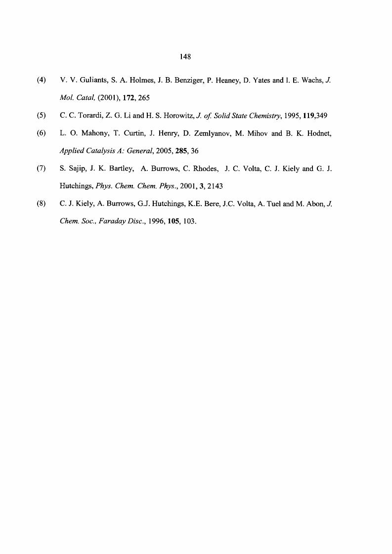
(4) V. V. Guliants, S. A. Holmes, J. B. Benziger, P. Heaney, D. Yates and I. E. Wachs, J.
Mol. Catal, (2001), 172, 265
(5) C. C. Torardi, Z. G. Li and H. S. Horowitz, J. of. Solid State Chemistry, 1995,119,349
(6) L. O. Mahony, T. Curtin, J. Henry, D. Zemlyanov, M. Mihov and B. K. Hodnet,
Applied Catalysis A: General, 2005, 285, 36
(7) S. Sajip, J. K. Bartley, A. Burrows, C. Rhodes, J. C. Volta, C. J. Kiely and G. J.
Hutchings, Phys. Chem. Chem. Phys., 2001, 3, 2143
(8) C. J. Kiely, A. Burrows, G.J. Hutchings, K.E. Bere, J.C. Volta, A. Tuel and M. Abon, J.
Chem. Soc., Faraday Disc., 1996,105, 103.
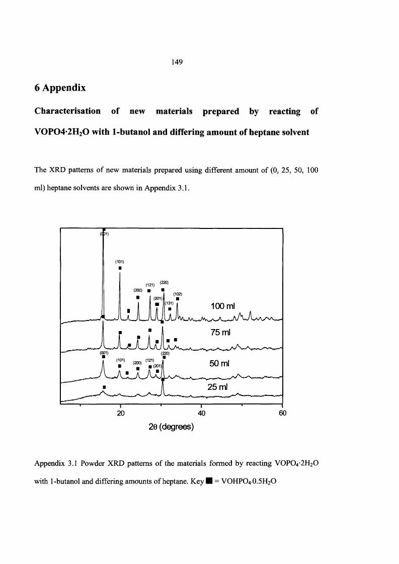
149
6 Appendix
Characterisation of new materials prepared by reacting of
V0P 04*2H 20 with 1-butanol and differing amount of heptane solvent
The XRD patterns o f new materials prepared using different amount o f (0, 25, 50, 100
ml) heptane solvents are shown in Appendix 3.1.
(0 1 )
(101)
(200)(102)
(201)(131) 100 ml
75 ml
(001)
20 40 60
20 (degrees)
Appendix 3.1 Powder XRD patterns o f the materials formed by reacting VOPO4 2 H2O
with 1-butanol and differing amounts o f heptane. K ey ■ = VOHPO4.O.5H2O
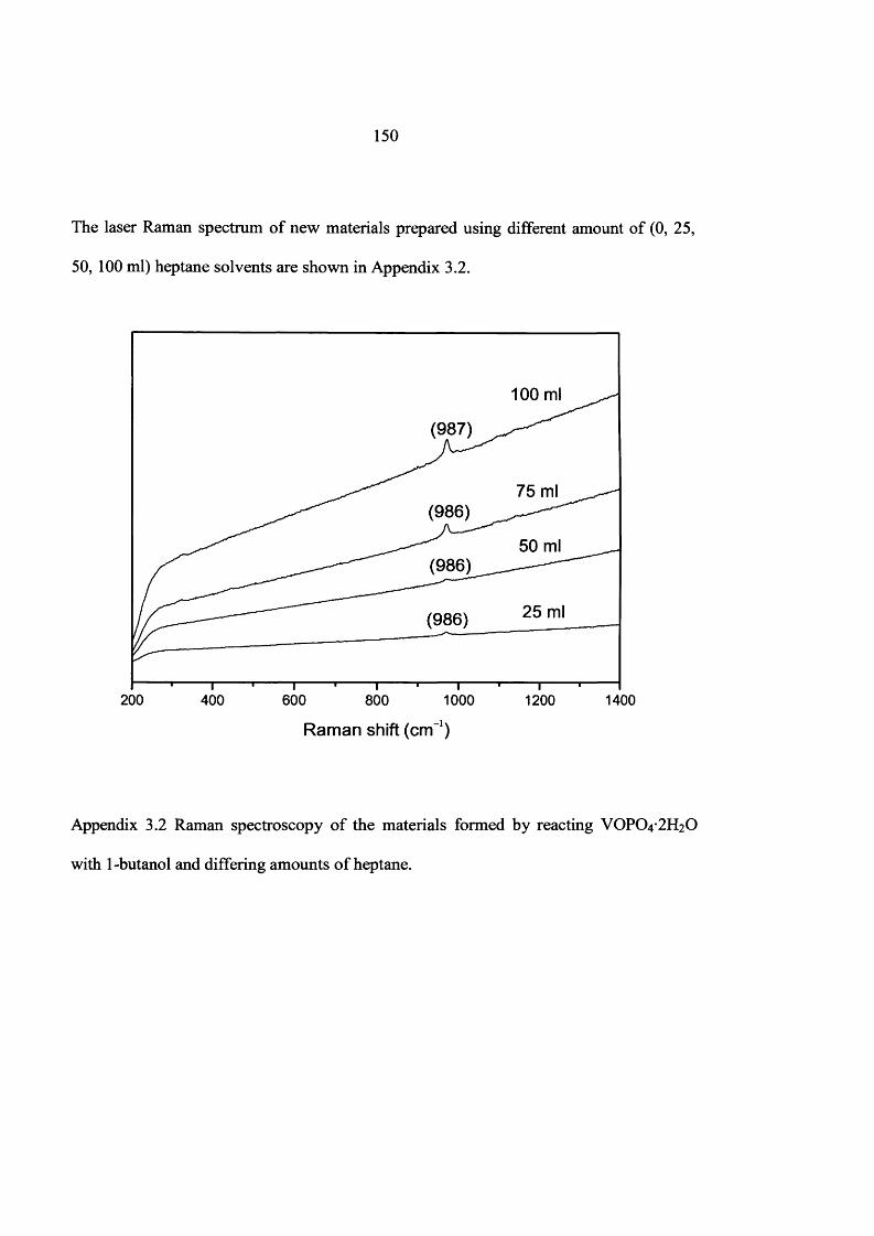
150
The laser Raman spectrum o f new materials prepared using different amount o f (0, 25,
50, 100 ml) heptane solvents are shown in Appendix 3.2.
100 ml
(987)
75 ml(986)
50 ml(986)
25 ml(986)
200 400 600 800 1000
Raman shift (cm-1)
1200 1400
Appendix 3.2 Raman spectroscopy o f the materials formed by reacting VOPO4 2 H2O
with 1-butanol and differing amounts o f heptane.
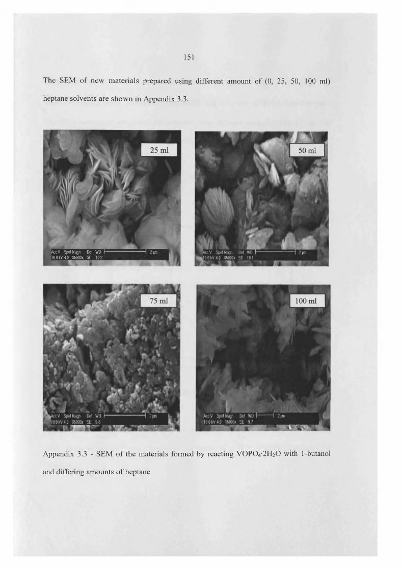
151
The SEM o f new materials prepared using different amount o f (0, 25, 50, 100 ml)
heptane solvents are shown in Appendix 3.3.
lAccV SpotMagn Det WD [10 0 kV 4.0 35000X SE 10.2
Appendix 3.3 - SEM o f the materials formed by reacting VOPO4 2 H2O with 1-butanol
and differing amounts o f heptane
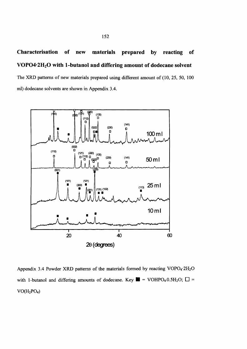
152
Characterisation of new materials prepared by reacting of
V0P04*2H20 with 1-butanol and differing amount of dodecane solvent
The XRD patterns o f new materials prepared using different amount o f (10, 25, 50, 100
ml) dodecane solvents are shown in Appendix 3.4.
100ml
(121) (220)
□ D , □ (2») C41) 50mlW>
(101) (121) ■ (200) ■ 25 ml
(131) (102)
10ml
20 (degrees)
Appendix 3.4 Powder XRD patterns o f the materials formed by reacting VOPO4 2 H2O
with 1-butanol and differing amounts o f dodecane. K ey H = VOHPO4 O.5H2O; □ =
V 0(H 2P 0 4)

153
The laser Raman spectrum o f new materials prepared using different amount o f (10, 25,
50, 100 ml) dodecane solvents are shown in Appendix 3.5.
100 ml
(937)
(986)50 ml
25 ml
10 ml
200 400 600 800 1000 1200 1400
Raman shift (cm'1)
Appendix 3.5 Raman spectroscopy o f the materials formed by reacting VOPO4 2 H2O
with 1-butanol and differing amounts o f dodecane.
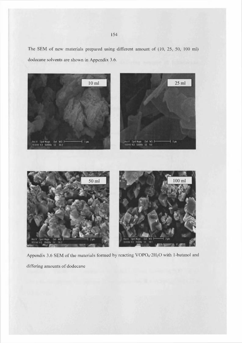
154
The SEM o f new materials prepared using different amount o f (10, 25, 50, 100 ml)
dodecane solvents are shown in Appendix 3.6.
Appendix 3.6 SEM of the materials formed by reacting V 0 P0 4 *2 H20 with 1-butanol and
differing amounts o f dodecane
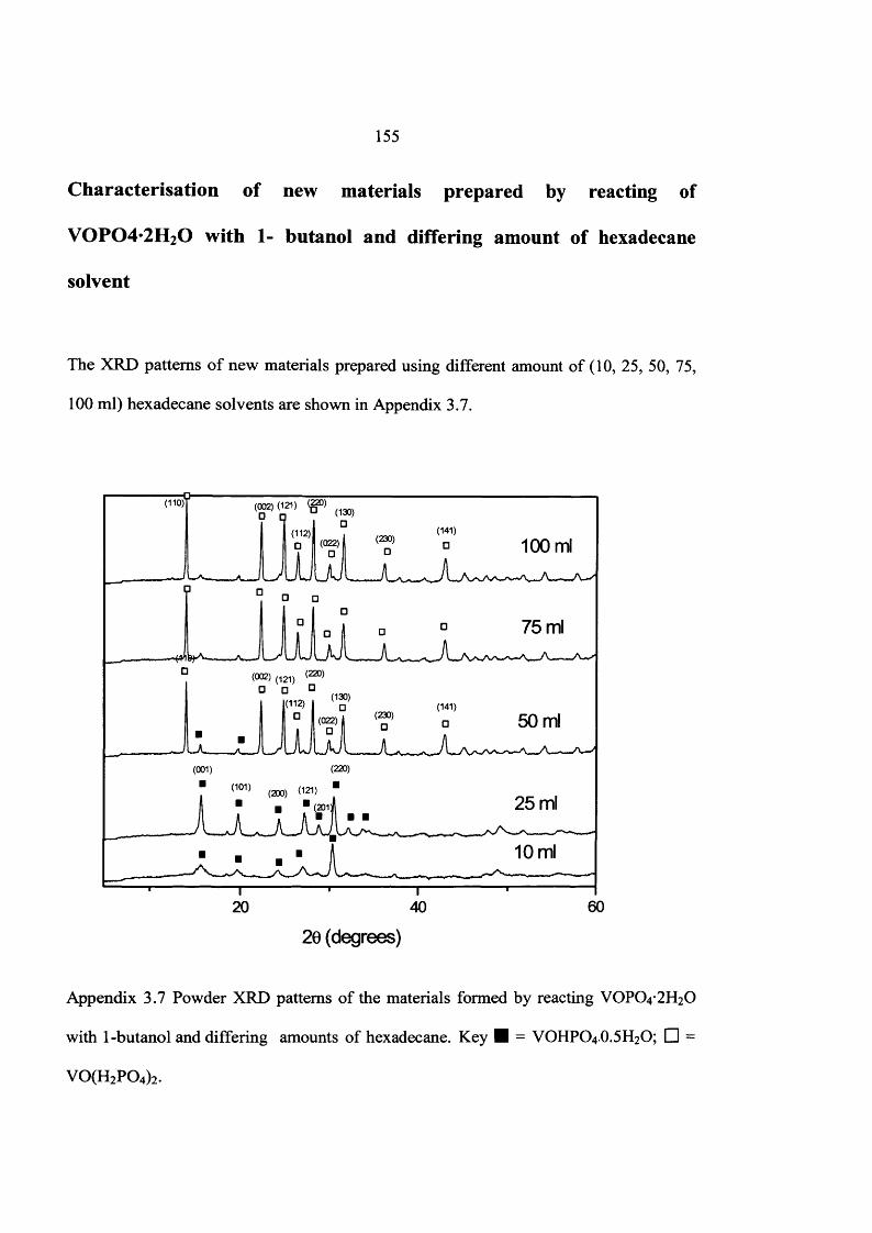
155
Characterisation of new materials prepared by reacting of
V 0 P 04 *2H 20 with 1- butanol and differing amount of hexadecane
solvent
The XRD patterns o f new materials prepared using different amount o f (10, 25, 50, 75,
100 ml) hexadecane solvents are shown in Appendix 3.7.
T o 211 <SDI <’*»I °(112) ,o (022)1
(110)
(141)(230) 100 ml
75 ml
(130)(112) (141)
(230) 50 ml(022)
(220)(001)
25 ml(201]
10 ml
6020 40
20 (degrees)
Appendix 3.7 Powder XRD patterns o f the materials formed by reacting VOPO4 2 H2O
with 1-butanol and differing amounts o f hexadecane. Key H = VOHPO4 O.5 H2O; □ =
V 0(H 2P 0 4)2.
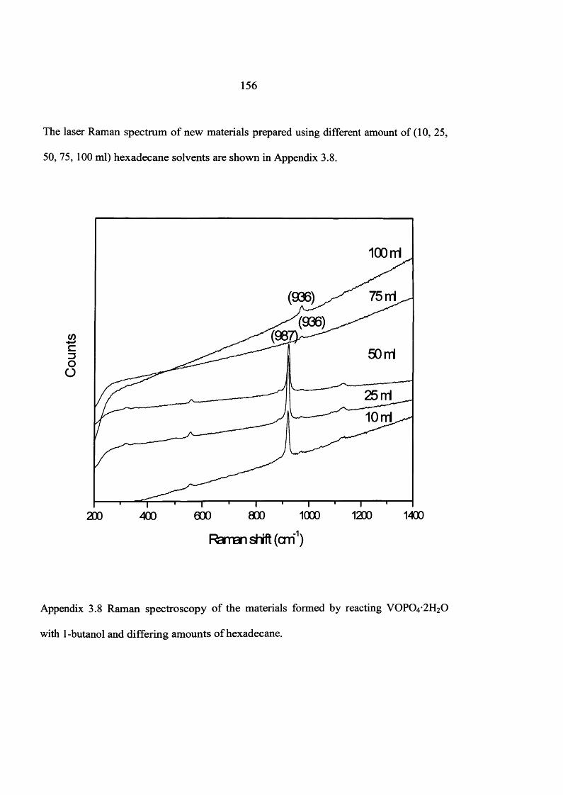
156
The laser Raman spectrum o f new materials prepared using different amount of (10, 25,
50, 75, 100 ml) hexadecane solvents are shown in Appendix 3.8.
100 rrl
(/)co
O
25 rrl
10 ml
200 400 eoo 800 1000 1200 1400
Raman shift (cm1)
Appendix 3.8 Raman spectroscopy o f the materials formed by reacting VOPO4 2 H2O
with 1 -butanol and differing amounts o f hexadecane.

157
The SEM o f new materials prepared using different amount o f (10, 25, 50, 75, 100 ml)
hexadecane solvents are shown in Appendix 3.9.
Appendix 3.9 SEM o f the materials formed by reacting VOPO4 2 H2O with 1-butanol and
differing amounts o f hexadecane.