the international r d systems 2017 - irds.ieee.org · libman, les marshall, supika mashiro, rick...
TRANSCRIPT
THE INTERNATIONAL ROADMAP FOR DEVICES AND SYSTEMS: 2017
INTERNATIONAL
ROADMAP
FOR
DEVICES AND SYSTEMS
2017 EDITION
FACTORY INTEGRATION
THE IRDS IS DEVISED AND INTENDED FOR TECHNOLOGY ASSESSMENT ONLY AND IS WITHOUT REGARD TO ANY
COMMERCIAL CONSIDERATIONS PERTAINING TO INDIVIDUAL PRODUCTS OR EQUIPMENT.
THE INTERNATIONAL ROADMAP FOR DEVICES AND SYSTEMS: 2017
Table of Contents
Acknowledgments .................................................................................................................... iv
1. Introduction .........................................................................................................................1
1.1. Current State of Technology ................................................................................................. 1
1.2. Drivers and Technology Targets........................................................................................... 2
1.3. Vision of Future Technology ................................................................................................. 3
1.4. Background Information ........................................................................................................ 4
2. Scope of Report ..................................................................................................................7
2.1. Introduction............................................................................................................................ 7
3. Summary and Key Points ...................................................................................................9
3.1. What Is New in the Transition from the International Technology Roadmap for Semiconductors (ITRS) 2.0 to the IRDS? ................................................................ 9
4. Challenges ........................................................................................................................10
5. Technology Requirements ...............................................................................................14
5.1. Summary ............................................................................................................................. 14
5.2. Factory Operations Needs .................................................................................................. 18
5.3. Production Equipment Needs ............................................................................................. 21
5.4. Material Handling Systems Needs ..................................................................................... 25
5.5. Factory Information and Control Systems Needs .............................................................. 25
5.6. Facilities Needs ................................................................................................................... 27
5.7. Augmenting Reactive with Predictive Needs...................................................................... 32
5.8. Big Data Needs ................................................................................................................... 34
5.9. Control Systems Architectures Needs ................................................................................ 38
6. Potential Solutions ............................................................................................................39
6.1. Factory Operations Potential Solutions .............................................................................. 41
6.2. Production Equipment Potential Solutions ......................................................................... 42
6.3. Material Handling Systems Potential Solutions .................................................................. 45
6.4. Factory Information and Control Systems Potential Solutions ........................................... 46
6.5. Facilities Potential Solutions ............................................................................................... 47
6.6. Augmenting Reactive with Predictive Potential Solutions .................................................. 48
6.7. Big Data Potential Solutions ............................................................................................... 50
6.8. Control Systems Architectures Potential Solutions ............................................................ 51
7. Cross Teams ....................................................................................................................51
7.1. Environmental, Safety, Health, and Sustainability (ESH/S) ............................................... 52
7.2. Yield Enhancement ............................................................................................................. 53
7.3. Metrology ............................................................................................................................. 55
7.4. Lithography.......................................................................................................................... 55
7.5. Multi-IFT Issue: Wafer Defect Metrology ............................................................................ 56
7.6. Multi-IFT Issue: Yield Management for Packaging and Assembly .................................... 56
THE INTERNATIONAL ROADMAP FOR DEVICES AND SYSTEMS: 2017
8. Emerging Concepts and Technologies ........................................................................... 56
8.1. Smart Manufacturing and Industry 4.0 ............................................................................... 56
8.2. Security ............................................................................................................................... 57
8.3. Supply Chain Management ................................................................................................ 58
9. Conclusions and Recommendations ............................................................................... 58
10. References .................................................................................................................. 59
List of Figures
Figure FAC1 Societal Forces Impacting Challenges and Opportunities in FI ................................3
Figure FAC2 Factory Integration Scope..........................................................................................7
Figure FAC3 Supply Chain Model SCOR .................................................................................... 21
Figure FAC4 Phased Scope of SEMI Standards Work to Support PE Energy Savings ............. 24
Figure FAC5 Total AMC concept ................................................................................................. 28
Figure FAC6 Example of Defining the Dimensions of Analytics Capabilities [3] ......................... 37
Figure FAC7 Factory Operations Potential Solutions .................................................................. 42
Figure FAC8 Production Equipment Potential Solutions ............................................................. 44
Figure FAC9 Material Handling Systems Potential Solutions...................................................... 45
Figure FAC10 Factory Information and Control Systems Potential Solutions............................... 46
Figure FAC11 Facilities Potential Solutions ................................................................................... 47
Figure FAC12 Augmenting Reactive with Predictive Potential Solutions ...................................... 49
Figure FAC13 Big Data Potential Solutions ................................................................................... 50
List of Tables
Table FAC1 Acronyms Used in This Report ..................................................................................4
Table FAC2 Standards Referenced in This Report .......................................................................5
Table FAC3 Difficult Challenges ................................................................................................. 10
Table FAC4 Key Focus Areas and Issues for FI Functional Areas Beyond 2017 ..................... 14
Table FAC5 Stabilized FI Metrics with Recommended Values (Critical but Educational Values) ............................................................................ 17
Table FAC6 Factory Operations Technology Requirements...................................................... 21
Table FAC7 Context Data Importance for Good Equipment Visibility ........................................ 23
Table FAC8 Production Equipment Technology Requirements ................................................. 25
Table FAC9 Material Handling Systems Technology Requirements ......................................... 25
Table FAC10 Factory Information and Control Systems Technology Requirements .................. 27
Table FAC11 Facilities Technology Requirements ...................................................................... 32
Table FAC12 Augmenting Reactive with Predictive (ARP) Technology Requirements ............. 34
Table FAC13 Big Data Technology Requirements ....................................................................... 38
Table FAC14 Stabilized FI Potential Solutions with Description .................................................. 40
Table FAC15 Crosscut Issues Relating to Factory Integration Delineated by IFT ...................... 51
Link to Factory Integration tables in Excel

THE INTERNATIONAL ROADMAP FOR DEVICES AND SYSTEMS: 2017
ACKNOWLEDGMENTS Factory Integration International Focus Team (IFT) active members— Daniel Babbs, Jonathan Chang, Gino Crispieri,
Peter Csatary, Mike Czerniak, Astrid Gettel, Ramond Goss, David Gross, Chih-Wei (David) Huang, Vladimir Kraz, Slava
Libman, Les Marshall, Supika Mashiro, Rick McKee, Steve Moffatt, Chris Muller, Andreas Neuber, Kevin Pate, Markus
Pfeffer, Lothar Pfitzner, Gavin Rider, Dave Roberts, Ines Thurner, Brad van Eck, and Makoto Yamamoto.
The Factory Integration IFT would also like to thank Semiconductor Equipment and Materials International (SEMI), the
Advanced Semiconductor Manufacturing Conference 2017 organizers, and the Advanced Process Control (APC) 2017
Conference organizers for supporting execution of our security survey; and the APC 2017 Conference organizers for hosting
the APC Council meeting in which security survey responses were consolidated and consensus was reached on Factory
Integration security challenges.
Introduction 1
THE INTERNATIONAL ROADMAP FOR DEVICES AND SYSTEMS: 2017
FACTORY INTEGRATION
1. INTRODUCTION The Factory Integration (FI) chapter of the IRDS is dedicated to ensuring that the microelectronics manufacturing
infrastructure contains the necessary components to produce items at affordable cost and high volume. Realizing the
potential of Moore’s Law requires taking full advantage of device feature size reductions, new materials, yield improvement
to near 100%, wafer size increases, and other manufacturing productivity improvements. This in turn requires a factory
system that can fully integrate additional factory components and utilize these components collectively to deliver items that
meet specifications determined by other IRDS international focus teams (IFTs) as well as cost, volume and yield targets.
Preserving the decades-long trend of 30% per year reduction in cost per function also requires capturing all possible cost
reduction opportunities. These include opportunities in front-end as well as back-end production, facilities, yield
management and improvement, increased system integration such as up and down the supply chain, and improving
environmental health and safety. FI challenges play a key role realizing these opportunities and many FI technology
challenges are becoming limiters to achieving major technology milestones.
1.1. CURRENT STATE OF TECHNOLOGY
The overall FI scope addresses several challenges/issues that threaten to slow the industry’s growth, including:
1. Complex business models with complex factories—Rapid changes in microelectronics technologies, business
requirements, and the need for faster product delivery, high mix, and volatile market conditions continue to make
effective and timely factory integration to meet accelerated ramp and yield targets more difficult over time. The
factory now must integrate an even larger number of new and different equipment types, software applications and
data to meet complex market objectives and customer requirements. High mix and low-volume product runs are
making mask cost, fabrication, and FI extremely difficult in a market where average selling prices are declining.
2. High potential of waste generation and inclusion in factory operations—Continuous improvement of factory
productivity with more comprehensive visualization and inclusion of waste and resource utilization targets is
necessary to achieve growth and cost targets.
3. Production equipment utilization and extendibility—Production equipment is not keeping up with reliability,
availability, and, utilization targets, which has an enormous impact on capital and operating costs. Reliability,
availability and especially utilization are also impacted by factory operation factors.
4. Significant productivity improvement either by next wafer size manufacturing paradigm or through 300 mm
manufacturing technology improvement—the industry needs to review the productivity losses in 300 mm and
improve prior to the next wafer size transition so to make this transition more cost-effective. Due in-part to the
challenges associated with transition to the next wafer size, the projected date for transition has been moved out
to 2025.
5. Augmenting reactive with predictive operations—The industry needs to augment the existing reactive mode of
operation, changing reactive operations to predictive operations wherever possible, but continuing to be able to
support reactive operation. This will provide significant opportunities for cost reduction and quality and capacity
improvement. Examples include predictive maintenance (PdM), metrology prediction via virtual metrology (VM),
fault prediction, predictive scheduling, and yield prediction.
6. Control system evolution—Control systems will continue to become more granular (e.g., lot-to-lot, to wafer-to-
wafer, to within wafer), and higher speed (e.g., run-to-run to real-time quality parameter control). Centralized
versus various levels of distributed control is also being evaluated, both in a horizontal (e.g., distributed
applications and control optimized across the supply chain) and vertical (e.g., internal tool fault detection tied to
higher level maintenance activities) sense. Big data characteristics including veracity (i.e., data quality including
accuracy, synchronization and context richness), value (including algorithms) and velocity (i.e., rates) must
improve to support the evolution of control systems and will also serve to realize new control system concepts.
7. Supply chain integration and management—FI connectivity up and down the supply chain leveraging the
accelerated information technology (IT) trends will be necessary to support tightening of production methods
(e.g., associated with lean manufacturing) and addressing business requirements (e.g., for yield correlation,
warranty traceability, and cost reduction).
2 Introduction
THE INTERNATIONAL ROADMAP FOR DEVICES AND SYSTEMS: 2017
8. Ramp-up of new technologies—Closer integration of the industry is required for successful ramp-up of new
technology nodes and device architectures. There is a need for improved hardware and software capabilities as
well as more rapid reliable deployment of these capabilities. Examples include process characterization involving
nascent device materials, chemicals, gases, and consumables; where the wafer process environments are far better
protected to prevent productivity degradation.
9. Security─Information security will be more challenging with the increase of data shared across the factory
integration space. For example, the concept of the “connected Fab,” which is one of central concepts of Industry
4.0/Smart Manufacturing, even indicates potential direct data exchanges beyond the factory integration space.
While data must be made available to promote fault detection and classification (FDC), predictive maintenance
(PdM), advanced process control (APC), etc. at more granular levels (e.g., lot based to single wafer oriented for
maximizing productivity), protection of data and intellectual property (IP) within data will become more
complicated and sometimes contradictive to needs of data availability. Key challenges are listed below: (Note that
some of these challenges are addressed in SEMI E169-0616: Guide for Equipment Information and System
Security, however this is a guide and thus does not contain any specific standards requirements.)
a. Protection of crucial production parameter data (e.g. recipe, equipment parameters) from unauthorized
viewing or changing within the factory including between factory, original equipment manufacturers (OEMs)
and 3rd party suppliers [1]
b. Managing access authentication mechanisms for both human and non-human entities (e.g., software program)
c. Managing user class read-write privileges to support user capabilities while preventing access that would
result in breach of IP security or factory operation issues
d. Achieving balance between data availability (e.g., log-data for improved equipment performance) and
protection of device manufacturer’s manufacturing IPs and equipment suppliers’ proprietary information (e.g.,
equipment design and control)
e. Maintaining software security levels when interacting with 3rd parties on the factory floor
f. Maintaining software and communication performance in the face of security measures such as antivirus
software operations or compartmentation firewalls.
g. Protecting quality and integrity of big data and application of big data analytics to identifying security issues
h. Protection of the facility’s instrumentation and control systems from attack
i. Protecting fab and equipment operation control systems from unauthorized operation or alteration from both
inside fab and outside
10. Challenges and issues associated with increased integration of FI with Yield and ESH solutions─As noted above
FI challenges and solutions directly impact aspects of ESH/S and Yield roadmaps and these roadmaps in turn place
requirements and provide direction for FI. This is exemplified in areas such as yield prediction and energy savings.
1.2. DRIVERS AND TECHNOLOGY TARGETS
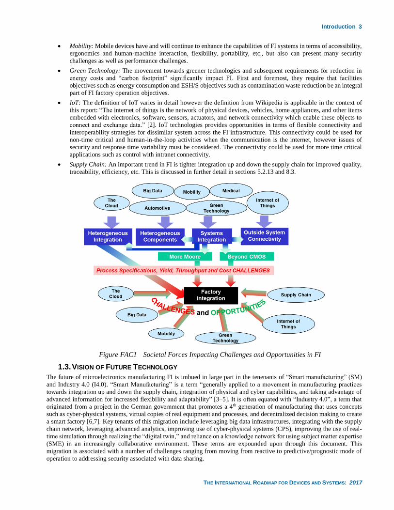
Societal driving forces and trends such mobile devices and the internet of things (IoT) are impacting all areas of the IRDS,
however, as shown in Figure FAC-1, these factors impact the evolution of FI from two perspectives, namely:
1. Requirements they place on product technologies that are delineated in roadmaps associated with other focus areas;
these technology requirements indirectly influence FI in terms of tighter process requirements with acceptable
yields, throughputs and costs.
2. Requirements they place on FI technologies that directly impact FI in terms of aligning with these trends and
effectively leveraging these capabilities.
An analysis of perspective 1) can be found by studying the roadmaps found in other focus groups as illustrated in Figure
FAC-1, and then determining how the FI roadmap addresses the related tighter process requirements. With respect to
perspective 2), the following is an example of how some of these drivers directly impact FI:
• The Cloud: The advent of the cloud and cloud-based technologies provides tremendous opportunities in terms of
analytics, addressing data volumes, coordination, enterprise-wide sharing and commonality and leveraging
capabilities across industries. However, it also presents challenges in terms of security from attack, security for IP
protection, and performance.
• Big Data: The data explosion in manufacturing provides both challenges and opportunities for FI; a section of the
FI chapter was created in the ITRS 2013 Edition and enhanced in the ITRS 2.0 2015 Edition, as well as in the
IRDS 2017 whitepaper that describes these in detail.
Introduction 3
THE INTERNATIONAL ROADMAP FOR DEVICES AND SYSTEMS: 2017
• Mobility: Mobile devices have and will continue to enhance the capabilities of FI systems in terms of accessibility,
ergonomics and human-machine interaction, flexibility, portability, etc., but also can present many security
challenges as well as performance challenges.
• Green Technology: The movement towards greener technologies and subsequent requirements for reduction in
energy costs and “carbon footprint” significantly impact FI. First and foremost, they require that facilities
objectives such as energy consumption and ESH/S objectives such as contamination waste reduction be an integral
part of FI factory operation objectives.
• IoT: The definition of IoT varies in detail however the definition from Wikipedia is applicable in the context of
this report: “The internet of things is the network of physical devices, vehicles, home appliances, and other items
embedded with electronics, software, sensors, actuators, and network connectivity which enable these objects to
connect and exchange data.” [2]. IoT technologies provides opportunities in terms of flexible connectivity and
interoperability strategies for dissimilar system across the FI infrastructure. This connectivity could be used for
non-time critical and human-in-the-loop activities when the communication is the internet, however issues of
security and response time variability must be considered. The connectivity could be used for more time critical
applications such as control with intranet connectivity.
• Supply Chain: An important trend in FI is tighter integration up and down the supply chain for improved quality,
traceability, efficiency, etc. This is discussed in further detail in sections 5.2.13 and 8.3.
Figure FAC1 Societal Forces Impacting Challenges and Opportunities in FI
1.3. VISION OF FUTURE TECHNOLOGY
The future of microelectronics manufacturing FI is imbued in large part in the tenenants of “Smart manufacturing” (SM)
and Industry 4.0 (I4.0). “Smart Manufacturing” is a term “generally applied to a movement in manufacturing practices
towards integration up and down the supply chain, integration of physical and cyber capabilities, and taking advantage of
advanced information for increased flexibility and adaptability” [3–5]. It is often equated with “Industry 4.0”, a term that
originated from a project in the German government that promotes a 4th generation of manufacturing that uses concepts
such as cyber-physical systems, virtual copies of real equipment and processes, and decentralized decision making to create
a smart factory [6,7]. Key tenants of this migration include leveraging big data infrastructures, integrating with the supply
chain network, leveraging advanced analytics, improving use of cyber-physical systems (CPS), improving the use of real-
time simulation through realizing the “digital twin,” and reliance on a knowledge network for using subject matter expertise
(SME) in an increasingly collaborative environment. These terms are expounded upon through this document. This
migration is associated with a number of challenges ranging from moving from reactive to predictive/prognostic mode of
operation to addressing security associated with data sharing.
4 Introduction
THE INTERNATIONAL ROADMAP FOR DEVICES AND SYSTEMS: 2017
1.4. BACKGROUND INFORMATION
Important information that can be referenced to help in the understanding of the Factory Integration Roadmap report is
found below. This includes a listing of acronyms used, standards referenced and an introduction to table types that are not
necessarily found in other IRDS reports. Note that documents cited in this report can be found in Section 10.
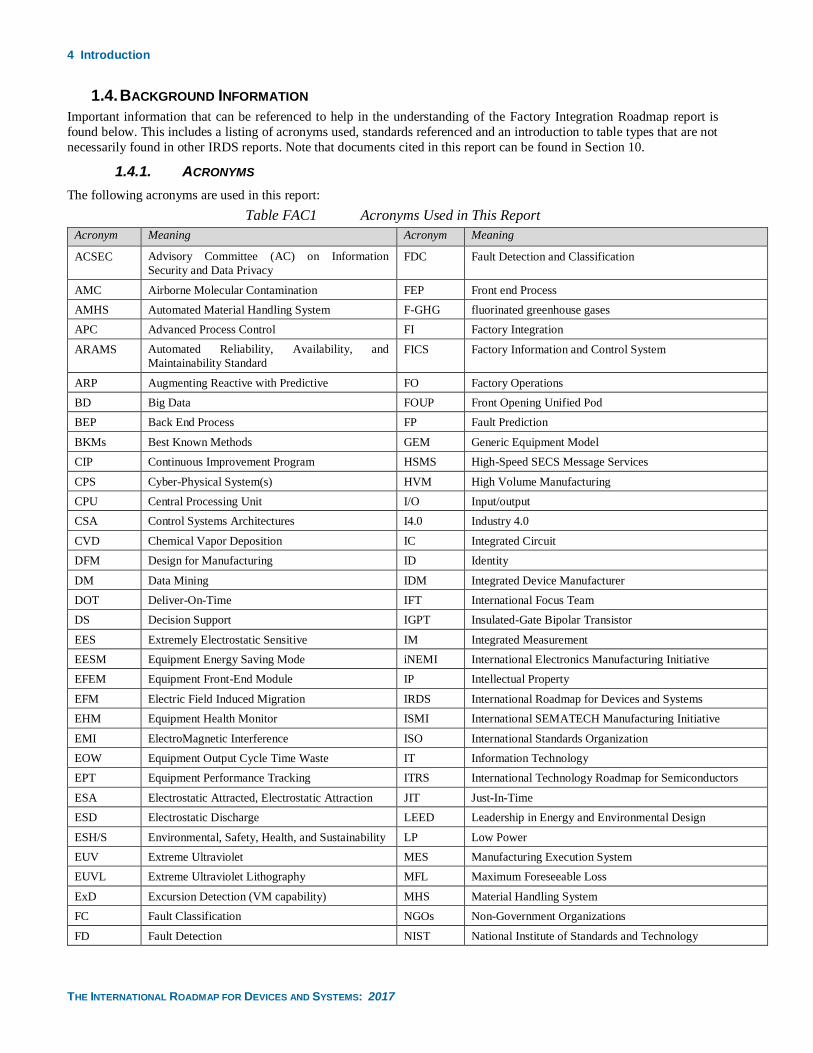
1.4.1. ACRONYMS
The following acronyms are used in this report:
Table FAC1 Acronyms Used in This Report
Acronym Meaning Acronym Meaning
ACSEC Advisory Committee (AC) on Information
Security and Data Privacy
FDC Fault Detection and Classification
AMC Airborne Molecular Contamination FEP Front end Process
AMHS Automated Material Handling System F-GHG fluorinated greenhouse gases
APC Advanced Process Control FI Factory Integration
ARAMS Automated Reliability, Availability, and
Maintainability Standard
FICS Factory Information and Control System
ARP Augmenting Reactive with Predictive FO Factory Operations
BD Big Data FOUP Front Opening Unified Pod
BEP Back End Process FP Fault Prediction
BKMs Best Known Methods GEM Generic Equipment Model
CIP Continuous Improvement Program HSMS High-Speed SECS Message Services
CPS Cyber-Physical System(s) HVM High Volume Manufacturing
CPU Central Processing Unit I/O Input/output
CSA Control Systems Architectures I4.0 Industry 4.0
CVD Chemical Vapor Deposition IC Integrated Circuit
DFM Design for Manufacturing ID Identity
DM Data Mining IDM Integrated Device Manufacturer
DOT Deliver-On-Time IFT International Focus Team
DS Decision Support IGPT Insulated-Gate Bipolar Transistor
EES Extremely Electrostatic Sensitive IM Integrated Measurement
EESM Equipment Energy Saving Mode iNEMI International Electronics Manufacturing Initiative
EFEM Equipment Front-End Module IP Intellectual Property
EFM Electric Field Induced Migration IRDS International Roadmap for Devices and Systems
EHM Equipment Health Monitor ISMI International SEMATECH Manufacturing Initiative
EMI ElectroMagnetic Interference ISO International Standards Organization
EOW Equipment Output Cycle Time Waste IT Information Technology
EPT Equipment Performance Tracking ITRS International Technology Roadmap for Semiconductors
ESA Electrostatic Attracted, Electrostatic Attraction JIT Just-In-Time
ESD Electrostatic Discharge LEED Leadership in Energy and Environmental Design
ESH/S Environmental, Safety, Health, and Sustainability LP Low Power
EUV Extreme Ultraviolet MES Manufacturing Execution System
EUVL Extreme Ultraviolet Lithography MFL Maximum Foreseeable Loss
ExD Excursion Detection (VM capability) MHS Material Handling System
FC Fault Classification NGOs Non-Government Organizations
FD Fault Detection NIST National Institute of Standards and Technology
Introduction 5
THE INTERNATIONAL ROADMAP FOR DEVICES AND SYSTEMS: 2017
Acronym Meaning Acronym Meaning
NPW Non-Product Wafer SECS SEMI Equipment Communication Standard
NTP Networked Time Protocol SEM/TEM Scanning Electron Microscopy/Transmission Electron
Microscopy
OEE Overall Equipment Efficiency SEMI Semiconductor Equipment and Material International
OEM Original Equipment Manufacturer SESMC Subsystem Energy Saving Mode Communication
PCL Predictive Carrier Logistics SFORMS Secured Foundation of Recipe Management Systems
PCS Process Control Systems SHL Super Hot Lots
PdM Predictive Maintenance SM Smart Metrology (a VM capability), Smart Manufacturing
PE Production Equipment SMC Surface Molecular Contamination
PFC Perfluorocarbon SME Subject Matter Expertise, or Subject Matter Expert
PIC Physical Interface and Carriers SOAP Simple Object Access Protocol
PM Preventative Maintenance SOS Software as a Service
POC Point of Connection SPC Statistical Process Control
POD Point of Delivery TH Throughput
POE Point of Entry TR Technical Requirements
POP Point of Process UF Ultra-Filtration
POS Point of Supplier UPW Ultra-Pure Water
POU Point of Use VM Virtual Metrology
PPM Predictive and Preventative Maintenance W2W Wafer-to-Wafer (control)
PTP Precision Time Protocol WIP Work in Process
R&D Research and Development WIW Within Wafer (control)
R2R Run-to-Run (control) WTW Wait Time Waste
RAM Reliability, Availability, and Maintainability XML eXtensible Markup Language
RM Real Metrology YEx Yield Excursion
ROI Return on Investment YMS Yield Management System
RUL Remaining Useful Life YP Yield Prediction
SCOR Supply Chain Operations Reference
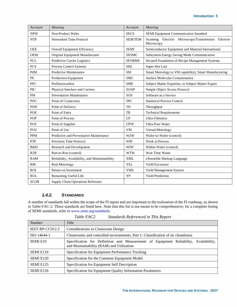
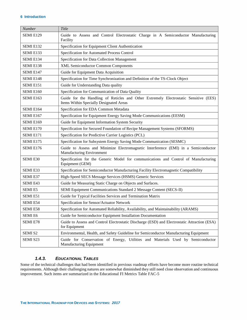
1.4.2. STANDARDS
A number of standards fall within the scope of the FI report and are important to the realization of the FI roadmap, as shown
in Table FAC-2. These standards are listed here. Note that this list is not meant to be comprehensive; for a complete listing
of SEMI standards, refer to www.semi.org/standards.
Table FAC2 Standards Referenced in This Report
Number Title
IEST-RP-CC012.2 Considerations in Cleanroom Design
ISO 14644-1 Cleanrooms and controlled environments, Part 1: Classification of air cleanliness
SEMI E10 Specification for Definition and Measurement of Equipment Reliability, Availability,
and Maintainability (RAM) and Utilization
SEMI E116 Specification for Equipment Performance Tracking
SEMI E120 Specification for the Common Equipment Model
SEMI E125 Specification for Equipment Self Description
SEMI E126 Specification for Equipment Quality Information Parameters
6 Introduction
THE INTERNATIONAL ROADMAP FOR DEVICES AND SYSTEMS: 2017
Number Title
SEMI E129 Guide to Assess and Control Electrostatic Charge in A Semiconductor Manufacturing
Facility
SEMI E132 Specification for Equipment Client Authentication
SEMI E133 Specification for Automated Process Control
SEMI E134 Specification for Data Collection Management
SEMI E138 XML Semiconductor Common Components
SEMI E147 Guide for Equipment Data Acquisition
SEMI E148 Specification for Time Synchronization and Definition of the TS-Clock Object
SEMI E151 Guide for Understanding Data quality
SEMI E160 Specification for Communication of Data Quality
SEMI E163 Guide for the Handling of Reticles and Other Extremely Electrostatic Sensitive (EES)
Items Within Specially Designated Areas
SEMI E164 Specification for EDA Common Metadata
SEMI E167 Specification for Equipment Energy Saving Mode Communications (EESM)
SEMI E169 Guide for Equipment Information System Security
SEMI E170 Specification for Secured Foundation of Recipe Management Systems (SFORMS)
SEMI E171 Specification for Predictive Carrier Logistics (PCL)
SEMI E175 Specification for Subsystem Energy Saving Mode Communication (SESMC)
SEMI E176 Guide to Assess and Minimize Electromagnetic Interference (EMI) in a Semiconductor
Manufacturing Environment
SEMI E30 Specification for the Generic Model for communications and Control of Manufacturing
Equipment (GEM)
SEMI E33 Specification for Semiconductor Manufacturing Facility Electromagnetic Compatibility
SEMI E37 High-Speed SECS Message Services (HSMS) Generic Services
SEMI E43 Guide for Measuring Static Charge on Objects and Surfaces.
SEMI E5 SEMI Equipment Communications Standard 2 Message Content (SECS-II)
SEMI E51 Guide for Typical Facilities Services and Termination Matrix
SEMI E54 Specification for Sensor/Actuator Network
SEMI E58 Specification for Automated Reliability, Availability, and Maintainability (ARAMS)
SEMI E6 Guide for Semiconductor Equipment Installation Documentation
SEMI E78 Guide to Assess and Control Electrostatic Discharge (ESD) and Electrostatic Attraction (ESA)
for Equipment
SEMI S2 Environmental, Health, and Safety Guideline for Semiconductor Manufacturing Equipment
SEMI S23 Guide for Conservation of Energy, Utilities and Materials Used by Semiconductor
Manufacturing Equipment
1.4.3. EDUCATIONAL TABLES
Some of the technical challenges that had been identified in previous roadmap efforts have become more routine technical
requirements. Although their challenging natures are somewhat diminished they still need close observation and continuous
improvement. Such items are summarized in the Educational FI Metrics Table FAC-5
Scope of Report 7
THE INTERNATIONAL ROADMAP FOR DEVICES AND SYSTEMS: 2017
Similarly, some of the potential solutions that were considered to address the technical challenges that had been identified
in previous roadmap efforts have been adopted but they are still in need of continuous improvement. Such former “potential”
solutions are summarized in the Educational Solutions Table FAC-14.
2. SCOPE OF REPORT
2.1. INTRODUCTION
Microelectronics manufacturing extends across several manufacturing domains. FI’s scope is microelectronic
manufacturing or fabrication in front-end and back-end. The FI Focus team has addressed evolution of FI by providing an
extensible roadmap that 1) focuses on the commonality of certain functional areas, 2) supports roadmaps for specific
functional and physical areas, 3) addresses societal drives identified above, and 4) provides for improved integration of
Environmental, Safety, Health, and Sustainability (ESH/S) and a portion of Yield) objectives, requirements and solution.
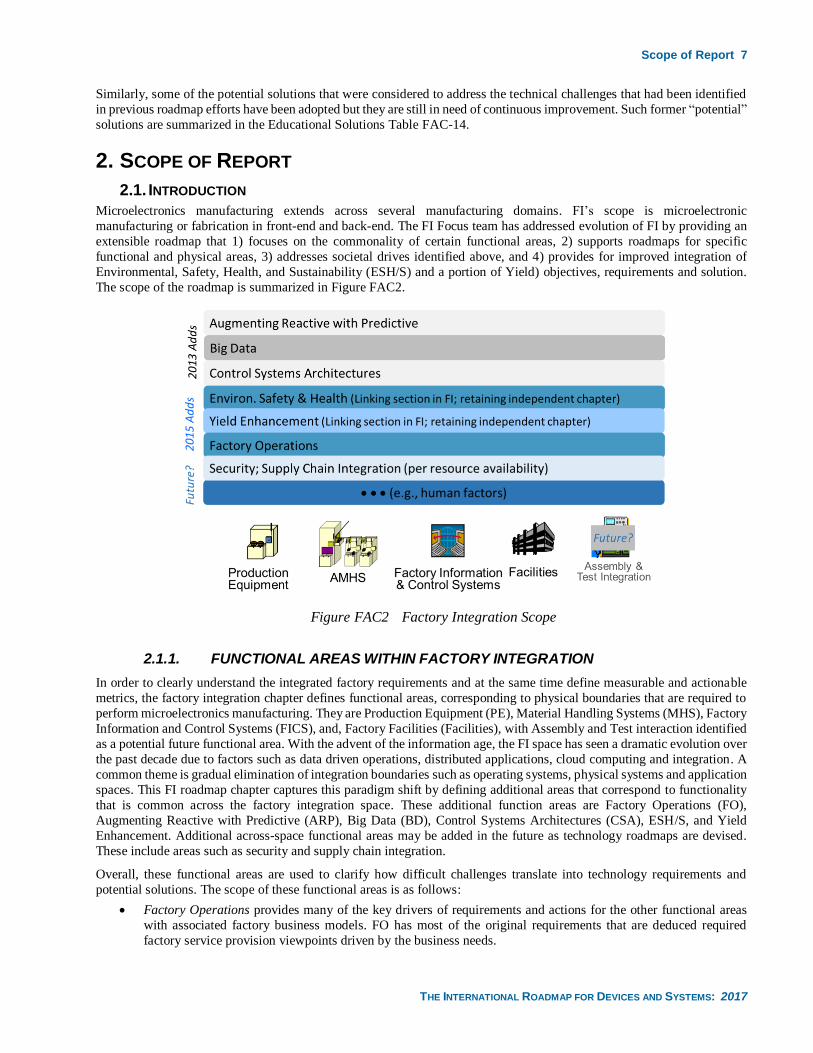
The scope of the roadmap is summarized in Figure FAC2.
Figure FAC2 Factory Integration Scope
2.1.1. FUNCTIONAL AREAS WITHIN FACTORY INTEGRATION
In order to clearly understand the integrated factory requirements and at the same time define measurable and actionable
metrics, the factory integration chapter defines functional areas, corresponding to physical boundaries that are required to
perform microelectronics manufacturing. They are Production Equipment (PE), Material Handling Systems (MHS), Factory
Information and Control Systems (FICS), and, Factory Facilities (Facilities), with Assembly and Test interaction identified
as a potential future functional area. With the advent of the information age, the FI space has seen a dramatic evolution over
the past decade due to factors such as data driven operations, distributed applications, cloud computing and integration. A
common theme is gradual elimination of integration boundaries such as operating systems, physical systems and application
spaces. This FI roadmap chapter captures this paradigm shift by defining additional areas that correspond to functionality
that is common across the factory integration space. These additional function areas are Factory Operations (FO),
Augmenting Reactive with Predictive (ARP), Big Data (BD), Control Systems Architectures (CSA), ESH/S, and Yield
Enhancement. Additional across-space functional areas may be added in the future as technology roadmaps are devised.
These include areas such as security and supply chain integration.
Overall, these functional areas are used to clarify how difficult challenges translate into technology requirements and
potential solutions. The scope of these functional areas is as follows:
• Factory Operations provides many of the key drivers of requirements and actions for the other functional areas
with associated factory business models. FO has most of the original requirements that are deduced required
factory service provision viewpoints driven by the business needs.
8 Scope of Report
THE INTERNATIONAL ROADMAP FOR DEVICES AND SYSTEMS: 2017
• Production Equipment covers process and metrology equipment and their interfaces to other factory elements. It
also focuses on addressing equipment related productivity losses.
• Material Handling Systems covers transport, storage, identification, tracking, and control of direct and indirect
materials. MHS covers requirements for the automated MHS hardware and control systems.
• Factory Information and Control Systems includes computer hardware and software, manufacturing execution and
decision support systems, factory scheduling, control and diagnostics associated with control of equipment and
material handling systems, and process control. FICS also covers decision making support systems for the
productivity waste visualization and reduction.
• Facilities include the infrastructure of buildings, utilities, and monitoring systems.
• Augmenting Reactive with Predictive covers augmenting of existing reactive technologies with predictive
technologies while retaining the reactive capabilities. These predictive technologies include Predictive
Maintenance (PdM), Fault Prediction (FP) Virtual Metrology (VM), predictive scheduling, yield prediction and
augmenting predictive capabilities of the factory with simulation and emulation.
• Big Data identifies the challenges and potential solutions associated with the increases in data generation, storage
and usage, and capabilities for higher data rates and additional equipment parameter data availability. It specifically
addresses the big data attributes of: volume, velocity, variety, veracity and value.
• Control Systems Architectures covers general trends in control that are common across the FI space. This includes
control solutions that directly interface with the equipment, such as process run-to-run control, but also higher-
level control solutions such as control of cycle time deviation, productivity deviation and on-time delivery
deviation. Control inside the equipment is generally not within the CSA scope. Trends addressed include the move
to more granular control (e.g., lot-to-lot, to wafer-to-wafer, to within wafer), higher speed control, higher quality
control methods, increase in control systems capabilities, the advent of new control paradigms such as fully
distributed (autonomous) control and machine learning, and new control platforms such as cloud-based.
• Environmental, Safety, Health, and Sustainability relationship to FI addresses a trend, namely the closer
relationship and interdependency of many issues and solutions in ESH/S with FI. This includes how many FI
potential solutions can be used to provide or enhance ESH/S solutions, and how ESH/S solutions will be more
fully integrated in the factory.
• Yield relationship to FI addresses a trend, namely the closer relationship and interdependency of many issues and
solutions in YE with FI. This includes how many FI potential solutions such as prediction can be used to improve
yield and how yield objectives will be more closely integrated into FI solutions.
In addition to these functional areas, the Factory Integration chapter also addresses the cross-cut issues associated with
other IFT efforts that cut across all of these FI functional areas.
2.1.2. FACTORS CONTRIBUTING TO DEFINING FACTORY INTEGRATION SCOPE
The following are key factors impacting the scope of FI
Addressing the evolution of Factory Integration—The FI Focus team has addressed evolution of FI by providing an
extensible roadmap that 1) focuses on the commonality of certain functional areas, 2) supports roadmaps for specific
functional and physical areas, 3) addresses societal drives identified above, and 4) provides for improved synergy with
ESH/S and YE objectives, requirements and solution (see below).
Improving integration of FI with ESH/S and Yield—In addressing the evolution of FI, the IRDS community realized that
many FI challenges and solutions directly impact aspects of the ESH/S and Yield roadmaps, and many of the requirements
of ESH/S and Yield roadmaps placed requirements and provide direction for FI. Thus, it became clear that improved
integration of these three areas was needed; as a result, sub-sections are included in the FI chapter cross-team section that
discuss the synergy with the ESH/S and Yield roadmaps, respectively.
Cross-leveraging 300 mm and 450 mm factory challenges—We have addressed several 300 mm challenges, but it is still
necessary to continue to address these challenges as we migrate to 450mm (circa 2025, as discussed in the Introduction).
We need to provide solutions that can be used in both domains as much as possible so as to leverage economy of scale and
resource pooling. FI issues such as: 1) cycle time improvement, 2) yield improvement, 3) productivity waste reduction, 4)
higher process controllability, and, 5) reduction in utilities, power consumption and emission with even more progressive
targets, should have very similar solutions and roadmaps in 300 mm and 450 mm. Other FI issues such as challenges in
AMHS and facilities will have solution components that are similar for 300 mm and 450 mm, but other components that
are different. This distinction is delineated in this report.
Summary and Key Points 9
THE INTERNATIONAL ROADMAP FOR DEVICES AND SYSTEMS: 2017
The re-emergence of 200 mm —The increased heterogeneity and variety of devices combined with market pressures such
as those associated with IoT solutions has given rise to 200 mm production as an important component of microelectronics
ecosystem. While basic tenants of FI challenges and potential solutions associated with 300 mm translate well to 200 mm,
there are specific FI challenges, such as connectivity, variability, and availability of replacement components that must be
addressed so that 200 mm can remain as a viable production capability in the ecosystem.
Impact of non-microelectronics-manufacturing FI technologies – As we move forward in Factory Integration, technology
solutions such as big data, supply chain integration, cloud-based computing and security developed across industries will
increasingly impact the microelectronics manufacturing FI roadmap. Thus, the FI roadmap will increasingly define the
roadmap for many technology solutions through reference to general manufacturing trends.
3. SUMMARY AND KEY POINTS The FI chapter of the IRDS is dedicated to ensuring that the microelectronics manufacturing infrastructure contains the
necessary components to produce items at affordable cost and high volume. This report summarizes the challenges and
potential solutions associated with that objective and plots a roadmap for addressing the challenges and incorporating the
potential solutions. These challenges and solutions are broken down by functional area, with some of the functional areas
aligned with a physical component of factory integration, such as PE or AMHS, and others aligned with overarching areas
such as ARP and big data. A signification portion of the FI roadmap addresses trends associated with smart manufacturing
and Industry 4.0, components of which are described throughout this report.
3.1. WHAT IS NEW IN THE TRANSITION FROM THE INTERNATIONAL TECHNOLOGY ROADMAP FOR
SEMICONDUCTORS (ITRS) 2.0 TO THE IRDS?
The Factory Integration chapter of the IRDS evolved from its counterpart in the ITRS 2.0 chapter [8,9]. This section
highlights some of the major efforts and changes associated with that evolution over the past year.
3.1.1. ENHANCEMENT OF BIG DATA SECTION
The big data evolution is occurring faster than originally anticipated. As a result, this trend as well as an improved
understanding of the big data trend, roadmap timelines have been updated and new and refined challenges and potential
solutions have been identified. As an example, it has been determined that limitations on length of data store archives will
disappear, thus an objective for data retention of “ALL” has been identified, which means that all historical data for that
data store is retained.
Additionally, there has been a significant increase in focus on analytics in FI, and this trend is better captured in the current
version of the IRDS FI roadmap, both in the big data and augmenting reactive with predictive sections.
3.1.2. EXPANSION OF NARRATIVE AND ROADMAP ITEMS ASSOCIATED WITH SECURITY
Security is an increasingly important topic that permeates through all aspects of manufacturing disciplines. While it is
expected that a security roadmap in microelectronics manufacturing will rely heavily on advancements in other
manufacturing areas, a framework for security in microelectronics manufacturing factory integration is still needed. E169-
0615: Guide for Equipment Information System Security (mentioned earlier) might contribute to a portion of this framework
(focusing on production equipment security). Although limited to production recipes executed in production equipment,
the current efforts associated with the development and expansion of E170 might also contribute elevated security
environment regarding recipe handling between FICS and production equipment. The current FI roadmap summarizes basic
security challenges and solution areas, such as data partitioning and IP security. Future roadmap versions will seek to better
define an evolving FI security roadmap by providing a security section in the roadmap that includes technology challenges
and potential solutions tables.
3.1.3. IMPROVED DISCUSSION OF VIRTUAL METROLOGY AND CROSS-CUT INTERACTION WITH
IRDS METROLOGY CHAPTER
As part of the cross-cut activities with the Metrology IFT, it was determined that more information was needed from the
community as to the role, state-of-the-art, and trends in virtual metrology. In response the Metrology and FI IFTs worked
together to execute a survey on virtual metrology in microelectronics manufacturing. The results of that survey are captured
in a white paper [10]. Key findings that relate to virtual metrology’s impact on FI challenges and solutions have been
incorporated into the ARP FI section as well as the crosscut table metrology entry.
10 Challenges
THE INTERNATIONAL ROADMAP FOR DEVICES AND SYSTEMS: 2017
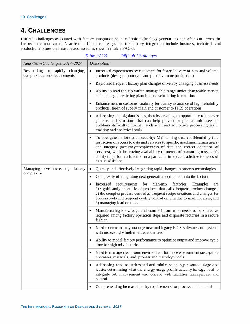
4. CHALLENGES Difficult challenges associated with factory integration span multiple technology generations and often cut across the
factory functional areas. Near-term difficult challenges for the factory integration include business, technical, and
productivity issues that must be addressed, as shown in Table FAC-3.
Table FAC3 Difficult Challenges
Near-Term Challenges: 2017–2024 Description
Responding to rapidly changing,
complex business requirements • Increased expectations by customers for faster delivery of new and volume
products (design à prototype and pilot à volume production)
• Rapid and frequent factory plan changes driven by changing business needs
• Ability to load the fab within manageable range under changeable market
demand, e.g., predicting planning and scheduling in real-time
• Enhancement in customer visibility for quality assurance of high reliability
products; tie-in of supply chain and customer to FICS operations
• Addressing the big data issues, thereby creating an opportunity to uncover
patterns and situations that can help prevent or predict unforeseeable
problems difficult to identify, such as current equipment processing/health
tracking and analytical tools
• To strengthen information security: Maintaining data confidentiality (the
restriction of access to data and services to specific machines/human users)
and integrity (accuracy/completeness of data and correct operation of
services), while improving availability (a means of measuring a system’s
ability to perform a function in a particular time) contradictive to needs of
data availability.
Managing ever-increasing factory
complexity • Quickly and effectively integrating rapid changes in process technologies
• Complexity of integrating next generation equipment into the factory
• Increased requirements for high-mix factories. Examples are
1) significantly short life of products that calls frequent product changes,
2) the complex process control as frequent recipe creations and changes for
process tools and frequent quality control criteria due to small lot sizes, and
3) managing load on tools
• Manufacturing knowledge and control information needs to be shared as
required among factory operation steps and disparate factories in a secure
fashion
• Need to concurrently manage new and legacy FICS software and systems
with increasingly high interdependencies
• Ability to model factory performance to optimize output and improve cycle
time for high mix factories
• Need to manage clean room environment for more environment susceptible
processes, materials, and, process and metrology tools
• Addressing need to understand and minimize energy resource usage and
waste; determining what the energy usage profile actually is; e.g., need to
integrate fab management and control with facilities management and
control
• Comprehending increased purity requirements for process and materials
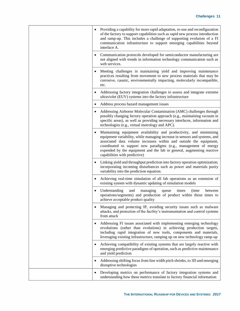
Challenges 11
THE INTERNATIONAL ROADMAP FOR DEVICES AND SYSTEMS: 2017
• Providing a capability for more rapid adaptation, re-use and reconfiguration
of the factory to support capabilities such as rapid new process introduction
and ramp-up. This includes a challenge of supporting evolution of a FI
communication infrastructure to support emerging capabilities beyond
interface A.
• Communication protocols developed for semiconductor manufacturing are
not aligned with trends in information technology communication such as
web services.
• Meeting challenges in maintaining yield and improving maintenance
practices resulting from movement to new process materials that may be
corrosive, caustic, environmentally impacting, molecularly incompatible,
etc.
• Addressing factory integration challenges to assess and integrate extreme
ultraviolet (EUV) systems into the factory infrastructure
• Address process hazard management issues
• Addressing Airborne Molecular Contamination (AMC) challenges through
possibly changing factory operation approach (e.g., maintaining vacuum in
specific areas), as well as providing necessary interfaces, information and
technologies (e.g., virtual metrology and APC).
• Maintaining equipment availability and productivity, and minimizing
equipment variability, while managing increase in sensors and systems, and
associated data volume increases within and outside the equipment,
coordinated to support new paradigms (e.g., management of energy
expended by the equipment and the fab in general, augmenting reactive
capabilities with predictive)
• Linking yield and throughput prediction into factory operation optimization;
incorporating incoming disturbances such as power and materials purity
variability into the prediction equation.
• Achieving real-time simulation of all fab operations as an extension of
existing system with dynamic updating of simulation models
• Understanding and managing queue times (time between
operations/segments) and production of product within those times to
achieve acceptable product quality
• Managing and protecting IP, avoiding security issues such as malware
attacks, and protection of the facility’s instrumentation and control systems
from attack
• Addressing FI issues associated with implementing emerging technology
revolutions (rather than evolutions) in achieving production targets,
including rapid integration of new tools, components and materials,
leveraging existing infrastructure, ramping up on new technology ramp-up
• Achieving compatibility of existing systems that are largely reactive with
emerging predictive paradigms of operation, such as predictive maintenance
and yield prediction
• Addressing shifting focus from line width pitch shrinks, to 3D and emerging
disruptive technologies
• Developing metrics on performance of factory integration systems and
understanding how these metrics translate to factory financial information
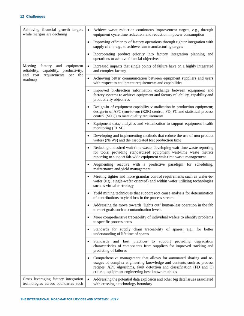
12 Challenges
THE INTERNATIONAL ROADMAP FOR DEVICES AND SYSTEMS: 2017
Achieving financial growth targets
while margins are declining • Achieve waste reduction continuous improvement targets, e.g., through
equipment cycle time reduction, and reduction in power consumption
• Improving efficiency of factory operations through tighter integration with
supply chain, e.g., to achieve lean manufacturing targets
• Incorporating product priority into factory integration planning and
operations to achieve financial objectives
Meeting factory and equipment
reliability, capability, productivity,
and cost requirements per the
roadmap
• Increased impacts that single points of failure have on a highly integrated
and complex factory
• Achieving better communication between equipment suppliers and users
with respect to equipment requirements and capabilities
• Improved bi-direction information exchange between equipment and
factory systems to achieve equipment and factory reliability, capability and
productivity objectives
• Design-in of equipment capability visualization in production equipment;
design-in of APC (run-to-run (R2R) control, FD, FC and statistical process
control (SPC)) to meet quality requirements
• Equipment data, analytics and visualization to support equipment health
monitoring (EHM)
• Developing and implementing methods that reduce the use of non-product
wafers (NPWs) and the associated lost production time
• Reducing undesired wait-time waste; developing wait-time waste reporting
for tools; providing standardized equipment wait-time waste metrics
reporting to support fab-wide equipment wait-time waste management
• Augmenting reactive with a predictive paradigm for scheduling,
maintenance and yield management
• Meeting tighter and more granular control requirements such as wafer-to-
wafer (e.g., single-wafer oriented) and within wafer utilizing technologies
such as virtual metrology
• Yield mining techniques that support root cause analysis for determination
of contributions to yield loss in the process stream.
• Addressing the move towards "lights out" human-less operation in the fab
to meet goals such as contamination levels.
• More comprehensive traceability of individual wafers to identify problems
to specific process areas
• Standards for supply chain traceability of spares, e.g., for better
understanding of lifetime of spares
• Standards and best practices to support providing degradation
characteristics of components from suppliers for improved tracking and
predicting of failures
• Comprehensive management that allows for automated sharing and re-
usages of complex engineering knowledge and contents such as process
recipes, APC algorithms, fault detection and classification (FD and C)
criteria, equipment engineering best known methods
Cross leveraging factory integration
technologies across boundaries such • Addressing the potential data explosion and other big data issues associated
with crossing a technology boundary
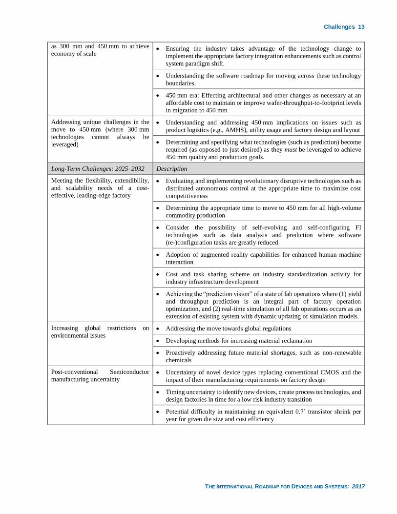
Challenges 13
THE INTERNATIONAL ROADMAP FOR DEVICES AND SYSTEMS: 2017
as 300 mm and 450 mm to achieve
economy of scale • Ensuring the industry takes advantage of the technology change to
implement the appropriate factory integration enhancements such as control
system paradigm shift.
• Understanding the software roadmap for moving across these technology
boundaries.
• 450 mm era: Effecting architectural and other changes as necessary at an
affordable cost to maintain or improve wafer-throughput-to-footprint levels
in migration to 450 mm
Addressing unique challenges in the
move to 450 mm (where 300 mm
technologies cannot always be
leveraged)
• Understanding and addressing 450 mm implications on issues such as
product logistics (e.g., AMHS), utility usage and factory design and layout
• Determining and specifying what technologies (such as prediction) become
required (as opposed to just desired) as they must be leveraged to achieve
450 mm quality and production goals.
Long-Term Challenges: 2025–2032 Description
Meeting the flexibility, extendibility,
and scalability needs of a cost-
effective, leading-edge factory
• Evaluating and implementing revolutionary disruptive technologies such as
distributed autonomous control at the appropriate time to maximize cost
competitiveness
• Determining the appropriate time to move to 450 mm for all high-volume
commodity production
• Consider the possibility of self-evolving and self-configuring FI
technologies such as data analysis and prediction where software
(re-)configuration tasks are greatly reduced
• Adoption of augmented reality capabilities for enhanced human machine
interaction
• Cost and task sharing scheme on industry standardization activity for
industry infrastructure development
• Achieving the “prediction vision” of a state of fab operations where (1) yield
and throughput prediction is an integral part of factory operation
optimization, and (2) real-time simulation of all fab operations occurs as an
extension of existing system with dynamic updating of simulation models.
Increasing global restrictions on
environmental issues • Addressing the move towards global regulations
• Developing methods for increasing material reclamation
• Proactively addressing future material shortages, such as non-renewable
chemicals
Post-conventional Semiconductor
manufacturing uncertainty • Uncertainty of novel device types replacing conventional CMOS and the
impact of their manufacturing requirements on factory design
• Timing uncertainty to identify new devices, create process technologies, and
design factories in time for a low risk industry transition
• Potential difficulty in maintaining an equivalent 0.7’ transistor shrink per
year for given die size and cost efficiency
14 Technology Requirements
THE INTERNATIONAL ROADMAP FOR DEVICES AND SYSTEMS: 2017
5. TECHNOLOGY REQUIREMENTS
5.1. SUMMARY
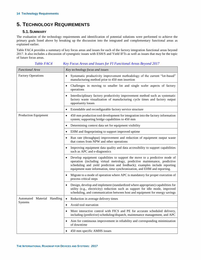
The evaluation of the technology requirements and identification of potential solutions were performed to achieve the
primary goals listed above by breaking up the discussion into the integrated and complementary functional areas as
explained earlier.
Table FAC4 provides a summary of key focus areas and issues for each of the factory integration functional areas beyond
2017. It also includes a discussion of synergistic issues with ESH/S and Yield IFTs as well as issues that may be the topic
of future focus areas.
Table FAC4 Key Focus Areas and Issues for FI Functional Areas Beyond 2017
Functional Area Key technology focus and issues
Factory Operations • Systematic productivity improvement methodology of the current “lot-based”
manufacturing method prior to 450 mm insertion
• Challenges in moving to smaller lot and single wafer aspects of factory
operations
• Interdisciplinary factory productivity improvement method such as systematic
factory waste visualization of manufacturing cycle times and factory output
opportunity losses
• Extendable and reconfigurable factory service structure
Production Equipment • 450 mm production tool development for integration into the factory information
system; supporting bridge capabilities to 450 mm
• Determining context data set for equipment visibility
• EHM and fingerprinting to support improved uptime
• Run rate (throughput) improvement and reduction of equipment output waste
that comes from NPW and other operations
• Improving equipment data quality and data accessibility to support capabilities
such as APC and e-diagnostics
• Develop equipment capabilities to support the move to a predictive mode of
operation (including virtual metrology, predictive maintenance, predictive
scheduling and yield prediction and feedback); examples include reporting
equipment state information, time synchronization, and EHM and reporting.
• Migrate to a mode of operation where APC is mandatory for proper execution of
process critical steps
• Design, develop and implement (standardized where appropriate) capabilities for
utility (e.g., electricity) reduction such as support for idle mode, improved
scheduling, and communication between host and equipment for energy savings
Automated Material Handling
Systems • Reduction in average delivery times
• Avoid tool starvation
• More interactive control with FICS and PE for accurate scheduled delivery,
including (predictive) scheduling/dispatch, maintenance management, and APC
• Aim for continuous improvement in reliability and corresponding minimization
of downtime
• 450 mm specific AMHS issues
Technology Requirements 15
THE INTERNATIONAL ROADMAP FOR DEVICES AND SYSTEMS: 2017
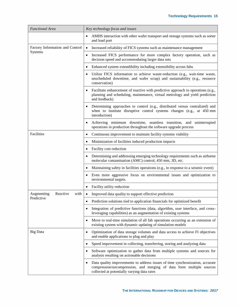
Functional Area Key technology focus and issues
• AMHS interaction with other wafer transport and storage systems such as sorter
and load port
Factory Information and Control
Systems • Increased reliability of FICS systems such as maintenance management
• Increased FICS performance for more complex factory operation, such as
decision speed and accommodating larger data sets
• Enhanced system extendibility including extensibility across fabs
• Utilize FICS information to achieve waste-reduction (e.g., wait-time waste,
unscheduled downtime, and wafer scrap) and sustainability (e.g., resource
conservation)
• Facilitate enhancement of reactive with predictive approach to operations (e.g.,
planning and scheduling, maintenance, virtual metrology and yield prediction
and feedback)
• Determining approaches to control (e.g., distributed versus centralized) and
when to institute disruptive control systems changes (e.g., at 450 mm
introduction)
• Achieving minimum downtime, seamless transition, and uninterrupted
operations in production throughout the software upgrade process
Facilities • Continuous improvement to maintain facility systems viability
• Minimization of facilities induced production impacts
• Facility cost reduction
• Determining and addressing emerging technology requirements such as airborne
molecular contamination (AMC) control, 450 mm, 3D, etc.
• Maintaining safety in facilities operations (e.g., in response to a seismic event)
• Even more aggressive focus on environmental issues and optimization to
environmental targets.
• Facility utility reduction
Augmenting Reactive with
Predictive • Improved data quality to support effective prediction
• Prediction solutions tied to application financials for optimized benefit
• Integration of predictive functions (data, algorithm, user interface, and cross-
leveraging capabilities) as an augmentation of existing systems
• Move to real-time simulation of all fab operations occurring as an extension of
existing system with dynamic updating of simulation models
Big Data • Optimization of data storage volumes and data access to achieve FI objectives
and enable applications to plug and play
• Speed improvement in collecting, transferring, storing and analyzing data
• Software optimization to gather data from multiple systems and sources for
analysis resulting on actionable decisions
• Data quality improvements to address issues of time synchronization, accurate
compression/uncompression, and merging of data form multiple sources
collected at potentially varying data rates
16 Technology Requirements
THE INTERNATIONAL ROADMAP FOR DEVICES AND SYSTEMS: 2017
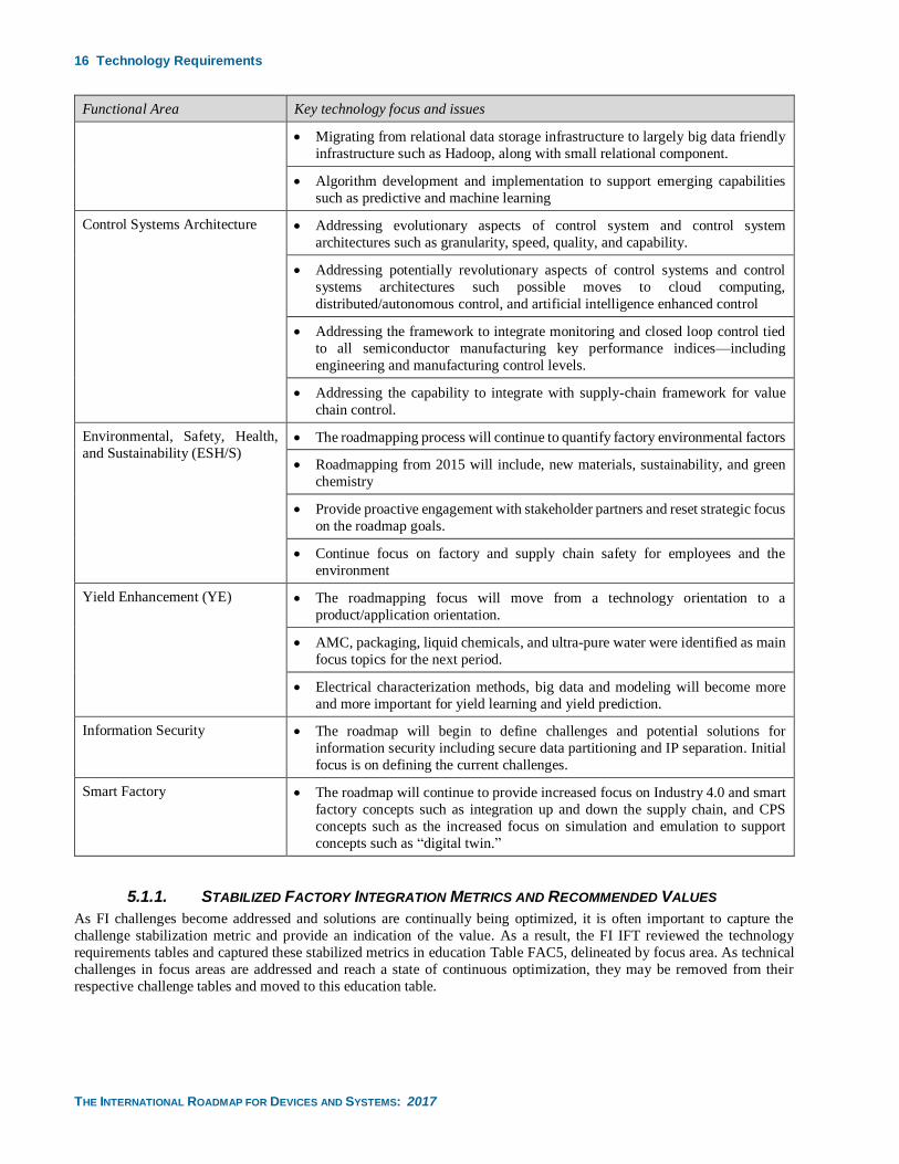
Functional Area Key technology focus and issues
• Migrating from relational data storage infrastructure to largely big data friendly
infrastructure such as Hadoop, along with small relational component.
• Algorithm development and implementation to support emerging capabilities
such as predictive and machine learning
Control Systems Architecture • Addressing evolutionary aspects of control system and control system
architectures such as granularity, speed, quality, and capability.
• Addressing potentially revolutionary aspects of control systems and control
systems architectures such possible moves to cloud computing,
distributed/autonomous control, and artificial intelligence enhanced control
• Addressing the framework to integrate monitoring and closed loop control tied
to all semiconductor manufacturing key performance indices—including
engineering and manufacturing control levels.
• Addressing the capability to integrate with supply-chain framework for value
chain control.
Environmental, Safety, Health,
and Sustainability (ESH/S) • The roadmapping process will continue to quantify factory environmental factors
• Roadmapping from 2015 will include, new materials, sustainability, and green
chemistry
• Provide proactive engagement with stakeholder partners and reset strategic focus
on the roadmap goals.
• Continue focus on factory and supply chain safety for employees and the
environment
Yield Enhancement (YE) • The roadmapping focus will move from a technology orientation to a
product/application orientation.
• AMC, packaging, liquid chemicals, and ultra-pure water were identified as main
focus topics for the next period.
• Electrical characterization methods, big data and modeling will become more
and more important for yield learning and yield prediction.
Information Security • The roadmap will begin to define challenges and potential solutions for
information security including secure data partitioning and IP separation. Initial
focus is on defining the current challenges.
Smart Factory • The roadmap will continue to provide increased focus on Industry 4.0 and smart
factory concepts such as integration up and down the supply chain, and CPS
concepts such as the increased focus on simulation and emulation to support
concepts such as “digital twin.”
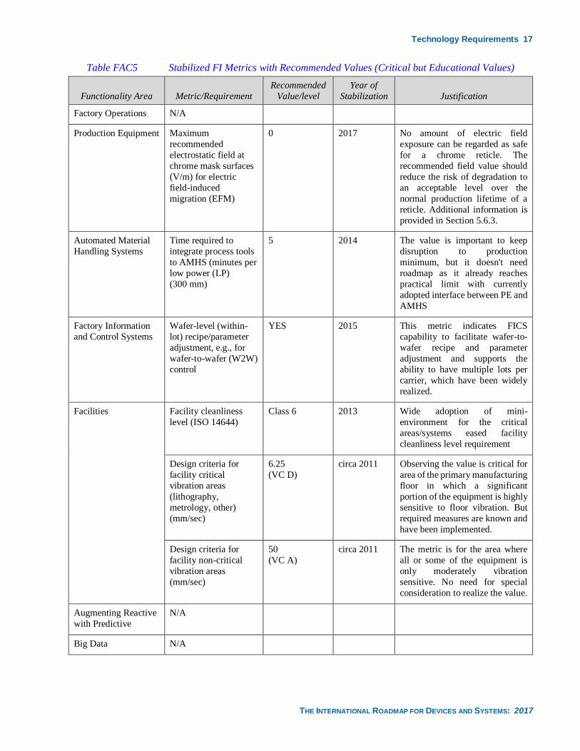
5.1.1. STABILIZED FACTORY INTEGRATION METRICS AND RECOMMENDED VALUES
As FI challenges become addressed and solutions are continually being optimized, it is often important to capture the
challenge stabilization metric and provide an indication of the value. As a result, the FI IFT reviewed the technology
requirements tables and captured these stabilized metrics in education Table FAC5, delineated by focus area. As technical
challenges in focus areas are addressed and reach a state of continuous optimization, they may be removed from their
respective challenge tables and moved to this education table.
Technology Requirements 17
THE INTERNATIONAL ROADMAP FOR DEVICES AND SYSTEMS: 2017
Table FAC5 Stabilized FI Metrics with Recommended Values (Critical but Educational Values)
Functionality Area Metric/Requirement
Recommended
Value/level
Year of
Stabilization Justification
Factory Operations N/A
Production Equipment Maximum
recommended
electrostatic field at
chrome mask surfaces
(V/m) for electric
field-induced
migration (EFM)
0 2017 No amount of electric field
exposure can be regarded as safe
for a chrome reticle. The
recommended field value should
reduce the risk of degradation to
an acceptable level over the
normal production lifetime of a
reticle. Additional information is
provided in Section 5.6.3.
Automated Material
Handling Systems
Time required to
integrate process tools
to AMHS (minutes per
low power (LP)
(300 mm)
5 2014 The value is important to keep
disruption to production
minimum, but it doesn't need
roadmap as it already reaches
practical limit with currently
adopted interface between PE and
AMHS
Factory Information
and Control Systems
Wafer-level (within-
lot) recipe/parameter
adjustment, e.g., for
wafer-to-wafer (W2W)
control
YES 2015 This metric indicates FICS
capability to facilitate wafer-to-
wafer recipe and parameter
adjustment and supports the
ability to have multiple lots per
carrier, which have been widely
realized.
Facilities Facility cleanliness
level (ISO 14644)
Class 6 2013 Wide adoption of mini-
environment for the critical
areas/systems eased facility
cleanliness level requirement
Design criteria for
facility critical
vibration areas
(lithography,
metrology, other)
(mm/sec)
6.25
(VC D)
circa 2011 Observing the value is critical for
area of the primary manufacturing
floor in which a significant
portion of the equipment is highly
sensitive to floor vibration. But
required measures are known and
have been implemented.
Design criteria for
facility non-critical
vibration areas
(mm/sec)
50
(VC A)
circa 2011 The metric is for the area where
all or some of the equipment is
only moderately vibration
sensitive. No need for special
consideration to realize the value.
Augmenting Reactive
with Predictive
N/A
Big Data N/A
18 Technology Requirements
THE INTERNATIONAL ROADMAP FOR DEVICES AND SYSTEMS: 2017
5.2. FACTORY OPERATIONS NEEDS
5.2.1. SYSTEMATIC FAB PRODUCTIVITY IMPROVEMENT
One of the most important missions of FI is to assist fab productivity improvement effort by providing productivity
information to those who are responsible at each of the hierarchical operation responsibility layers and providing means to
evaluate the improvement before and after implementation. There should be methodologies to identify the room for
improvement as Continuous Improvement Program (CIP) and the planning of strategic improvement. For these
methodologies to be effective the factory activity information is to be designed to have rationalized structures to facilitate
high data utilization for decision makings. It is also imperative to define commonly usable productivity metrics so that the
productivity improvement activities can cooperate among many. The FI IFT has concluded that such metrics are expressed
as productivity waste.
5.2.2. AGILITY AND FLEXIBILITY IN FACTORY SERVICES
Factory services are numerous but are required to change in a short period of time to accommodate various business
demands. The process control methods change as a new process generation is introduced. Process recipes are changed as a
new product or technology is introduced. The line capacity is re-optimized upon a new product introduction. Fab capacity
control and corresponding decision makings need to be agile and flexible. Decision making support capabilities such as
predictive visualization of cycle time, work in progress (WIP) and line throughput are becoming more important.
5.2.3. HIGH GRANULARITY AND PROACTIVE SERVICES
Finer material handling operation is required due to strong demand on cycle time reduction. More real-time control of PE
is required to meet elaborated process control requirements such as wafer-to-wafer and within wafer APC. Frequent
confirmation of production equipment healthiness using capabilities such as EHM is required to reduce the potential of
wafer scrap. Finer wafer-level product quality traceability is required while lot-based manufacturing is employed. All of
these trends are associated with a general trend of finer and more proactive (predictive) process and quality control.
5.2.4. HIERARCHICAL OPERATION STRUCTURE AND MANUFACTURING CONTROL OPERATION
Hierarchical structure in the manufacturing control operation is required to provide a counter-measure to the increased
complexity in manufacturing decision makings and fast control execution. FO structure needs to be designed to enable the
comprehensive optimization of FO for the required productivity. A good example is the hierarchical quality assurance in
which the wafer fabrication execution control and process outcome control are hierarchically delineated with aid of
increased visibility of the individual hierarchical layers.
The manufacturing control paradigm may change over time as capabilities such as cloud computing, application-based
integration and control (“apps”), and autonomous and semi-autonomous control are explored and evaluated for various FO
applications. Trends will be more closely aligned with other manufacturing arenas (than in the past) in order to leverage
technology innovation and economy of scale. At this time a roadmap for the evolution and paradigm shift of manufacturing
control cannot be fully realized because directions are not yet clear. These concepts are explored further in the Control
Systems Evolution section.
5.2.5. INTEGRATION OF FACILITIES REQUIREMENTS INTO FACTORY OPERATIONS
The increasing pressure of achieving goals such as environmentally benign and safe operation of fabs as well as utility cost
reduction will require that factory and facilities operations be coordinated. This will require increased attention to facility
objectives in factory objective functions. See also the Facilities section.
5.2.6. SIGNIFICANT PRODUCTIVITY IMPROVEMENT
A focus of the FO Technology Requirements Table FAC-6 is challenges associated with significant productivity
improvement of the current technology preceding the 450 mm insertion.
This waste reduction is to meet 30% 300 mm wafer cost reduction and 50% cycle time reduction. The implementation of
such significant improvement will be somewhat delayed due to the current economic situation and the speed of development
and adoption of standards for wait-time-waste and related metrics.
Equipment variation reduction will be a source of productivity improvement. In the future this may be quantified in table
entries in this section as metrics are agreed upon for the quantification of this source of improvement.
5.2.7. FUTURE MANUFACTURING REQUIREMENTS
The industry can focus on common technology development for 300 mm and 450 mm. 450 mm factories would benefit by
adaption of improved technology validated for 300 mm. FO metrics were reviewed and modified to reflect the future
Technology Requirements 19
THE INTERNATIONAL ROADMAP FOR DEVICES AND SYSTEMS: 2017
manufacturing, including 450 mm needs. Industry should study the implication of the FO Technology Requirements Table
FAC-6 and other FI technology requirements tables.
5.2.8. WASTE REDUCTION METRICS
Equipment Output Waste (EOW) is in the FO Technology Requirements Table FAC-6 with intent of aligning the significant
productivity improvement scheme. It is beyond the FI’s task to capture all of the waste types in the roadmap. It is important
to introduce more comprehensive waste metrics for FI so as to address the direction of overall productivity optimization of
highly complicated manufacturing system. These need to be comprehensive and measurable factory-level waste metrics.
Addressing the issue of waste reduction metrics will promote new manufacturing concepts, manufacturing control models,
and algorithms.
It is also the FI IFTs mission to induce the environment where the industry can collaboratively address the waste
visualization and reduction needs. Metrics definition and measurement method standardization are good examples of these
efforts.
5.2.9. DATA USAGES
The stringent engineering requirement is driving need for more data that would result in so-called data explosion. This is
explored in detail in the FI “Big Data” section. It is critical not only to collect necessary data but also to develop intelligent
analysis and algorithms to identify and use the right signals to make data driven decisions and reuse such intelligence as
models in later occasions. The factory data shall be designed in accordance to these models with usages for high data
utilization efficiencies.
5.2.10. 450 MM RELATED METRICS
450 mm specific requirement has been discussed in order to seek any FO Technology Requirements Table items. Although
the factory services requirements specific to 450 mm manufacturing have not been identified in the current roadmap,
300 mm factory services are expected to be applicable to 450 mm and so do the FO requirements captured. There may be
different requirements in 450 mm for the FO. The distinct example is cycle time requirement. The longer factory cycle time
requirements are expected since the beam production equipment such as lithography exposure tools and inspection tools
inevitably have a longer cycle times compared to the similar 300 mm tools (since the process time is proportional to the
area of treatment (beamscan).
Readers are encouraged to read the FO Technology Requirements Table FAC-6 with wafer size dependency in mind, but
should not read all the same fab operation characteristic values as 300 mm being required for 450 mm. From the waste
reduction view point, there should be much similarity between 300 mm and 450 mm requirements, but more study is needed
for WTW as discussed earlier. As 450 mm factory services requirements and physical ones become available IRDS FI will
capture 450 mm specific items into respective FI technology requirements tables.
5.2.11. OPERATIONAL PARADIGMS RELATED TO LOT SIZE
Production goals that include flexibility, cycle time reduction and demand optimization in high-mix environments have led
to the consideration of a number of operational paradigms that facilitate these goals. The paradigms include:
• Single wafer processing—which is defined in this chapter as processing one wafer at a time in an equipment
chamber. Wafer transport is not specified (and may be wafer-based or lot-based). Single wafer processing is
prevalent in many processes today and allows for increased flexibility in scheduling to demand as well as improved
effectiveness of FI capabilities such as process control and fault detection.
• Multi-product mixed-lots processing—is defined in this chapter as a type of single wafer processing where wafer
transport is multi-wafer lot-based, however multiple products can exist within the lot. The total number of wafers
in the lot is not fixed and can be less than 25 or variable. The impact is optimal AMHS capacity and decreased
cycle time, especially in high-mix environments that include low running products (i.e., having a relatively small
percentage of the overall product mix) along with high running products (i.e., having a relatively large percentage
of the overall product mix). Multi-product mixed-lots processing is relatively rare in current microelectronics
manufacturing practice but should become more prevalent over time as the need for flexibility increases and FI
systems become better equipped to manage this processing paradigm.
• Single wafer manufacturing—is defined in this chapter to mean a lot size equal to one wafer throughout the fab.
Thus, both single wafer processing and single wafer transport are employed.
20 Technology Requirements
THE INTERNATIONAL ROADMAP FOR DEVICES AND SYSTEMS: 2017
The paradigm shift to single wafer manufacturing is not occurring as soon as originally expected, and it is unknown if this
paradigm shift will ever take place on a large scale. FO roadmaps and FI roadmaps in general must address the challenges
and potential solutions associated with the operational paradigms that are adopted.
5.2.12. ASSEMBLY TEST INTEGRATION
As the industry moves forward in microelectronics manufacturing there is an increased focus on integration in and with
backend processes, with the goal of improving final product performance. As a result, there are increased opportunities for
product improvement coming from potential solutions in assembly and test operation and integration with each other and
front-end operations. In the past microelectronics manufacturing pursued advanced manufacturing methods to support
advanced FE process technology (e.g., e-Manufacturing SEMATECH initiatives in 2003), which have been defined and
implemented providing performance improvement in areas such as FICS, AMHS and equipment engineering control.
However, FE e-Manufacturing leverages a number of standards that requires a high cost to implement. Recent developments
such as Industry 4.0/Smart Manufacturing (references provided earlier) cite technologies including IoT, big data, and
robotics as enablers for new capabilities to support back-end (BE) manufacturing. These capabilities would support
potential solutions that address issues such as huge deviation in product, production and equipment in BE areas to achieve
manufacturing excellence in cost-effective way. Examples include leveraging IoT to enable data collection for all objects
in factory and using big data capabilities to enable advanced manufacturing intelligence and prediction capabilities. Industry
4.0 concepts will enable improved assembly and test with e-Manufacturing performance with lower cost. FI will identify
the potential opportunities from emerging technologies such as those cited in Industry 4.0 to enable advanced e-
Manufacturing in assembly and test for advanced manufacturing excellence. So, the focus on providing potential solutions
in assembly and test in the future will be 1) increased focus on assembly test to support new devices which rely more heavily
on BE excellence, 2) leverage new concepts such as those cited in Industry 4.0 in formulating BE potential solutions, and
3) leveraging potential solutions already identified for front-end (FE) into and with the BE.
5.2.13. SUPPLY CHAIN INTEGRATION
Factory performance depends on overall deviation control of all factors (man, machine, material, method). The factory is
part of the overall supply chain (see Supply Chain Operations Reference—SCOR model in Figure FAC3)1. Besides
continuous improvement of factory deviation control to improve manufacturing performance, there are other sources of
deviation from the overall supply chain into factory that also require good control to reduce the deviation and improve the
complexity management. There are several key parameters that should be considered in the control formulation; the
inclusion of these parameters in the control does not necessarily mean that these factors are under control:
1. Demand Forecast Deviation: the demand is considered the beginning of the downstream supply chain; forecast of
demand is not easy to determine because the demand has high complexity. Even if we could define the measure to
detect the deviation of demand forecast, there are no known methods to assure quality of demand forecast.
2. Demand Deviation: The microelectronics factory operating near capacity requires a long lead time for preparation
and qualification of equipment and processes. Demand deviation can thus result in extra cost associated with lost
capacity. The complexity of demand change control depends on the scale of overall supply chain. Having more
suppliers or customers for any given factory will increase the complexity and further increase the difficulty of
controlling the demand. There can be no automatic control of demand deviation; the factory role is to provide a
better response to this deviation.
3. Supply Chain Operation Deviation in the downstream supply chain: Microelectronics devices could be packed into
high-value added packages and installed into higher-value product. For example: the chips could be packed into
the insulated gate bipolar transistor (IGPT) modules and finally installed into electric cars. Any deviation from
supply chain will cause high cost. To assure good control of these deviations, the traceability of these chips (in the
downstream supply chain), components and final product are important. It requires a robust FI system to
automatically collect, store, and trace all supply chain operations.
4. Supply Chain Operation Deviation in the upstream supply chain; It is important to maintain traceability in the
upstream supply chain to manage part and consumable inventory as well as quality, for improved production
quality, reliability, and yield.
1 One source of information on SCOR is the APICS Supply Chain Council, which “advances supply chains through research,
benchmarking, and publications”. www.apics.org
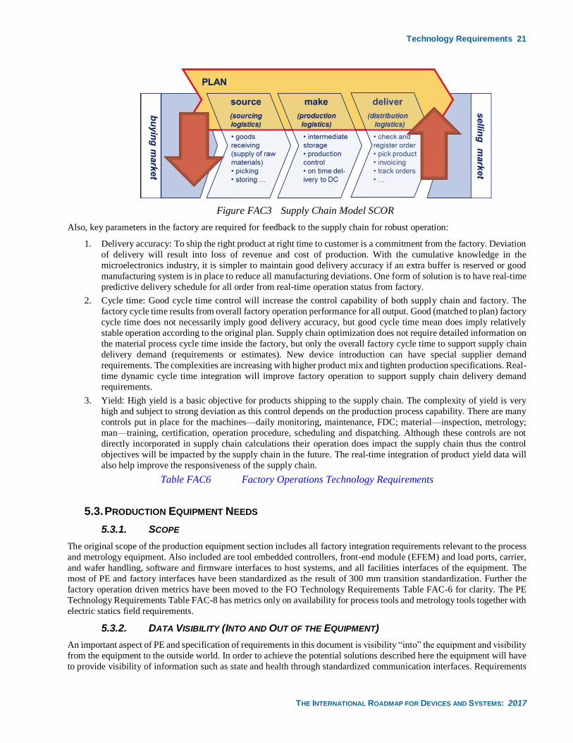
Technology Requirements 21
THE INTERNATIONAL ROADMAP FOR DEVICES AND SYSTEMS: 2017
Figure FAC3 Supply Chain Model SCOR
Also, key parameters in the factory are required for feedback to the supply chain for robust operation:
1. Delivery accuracy: To ship the right product at right time to customer is a commitment from the factory. Deviation
of delivery will result into loss of revenue and cost of production. With the cumulative knowledge in the
microelectronics industry, it is simpler to maintain good delivery accuracy if an extra buffer is reserved or good
manufacturing system is in place to reduce all manufacturing deviations. One form of solution is to have real-time
predictive delivery schedule for all order from real-time operation status from factory.
2. Cycle time: Good cycle time control will increase the control capability of both supply chain and factory. The
factory cycle time results from overall factory operation performance for all output. Good (matched to plan) factory
cycle time does not necessarily imply good delivery accuracy, but good cycle time mean does imply relatively
stable operation according to the original plan. Supply chain optimization does not require detailed information on
the material process cycle time inside the factory, but only the overall factory cycle time to support supply chain
delivery demand (requirements or estimates). New device introduction can have special supplier demand
requirements. The complexities are increasing with higher product mix and tighten production specifications. Real-
time dynamic cycle time integration will improve factory operation to support supply chain delivery demand
requirements.
3. Yield: High yield is a basic objective for products shipping to the supply chain. The complexity of yield is very
high and subject to strong deviation as this control depends on the production process capability. There are many
controls put in place for the machines—daily monitoring, maintenance, FDC; material—inspection, metrology;
man—training, certification, operation procedure, scheduling and dispatching. Although these controls are not
directly incorporated in supply chain calculations their operation does impact the supply chain thus the control
objectives will be impacted by the supply chain in the future. The real-time integration of product yield data will
also help improve the responsiveness of the supply chain.
Table FAC6 Factory Operations Technology Requirements
5.3. PRODUCTION EQUIPMENT NEEDS
5.3.1. SCOPE
The original scope of the production equipment section includes all factory integration requirements relevant to the process
and metrology equipment. Also included are tool embedded controllers, front-end module (EFEM) and load ports, carrier,
and wafer handling, software and firmware interfaces to host systems, and all facilities interfaces of the equipment. The
most of PE and factory interfaces have been standardized as the result of 300 mm transition standardization. Further the
factory operation driven metrics have been moved to the FO Technology Requirements Table FAC-6 for clarity. The PE
Technology Requirements Table FAC-8 has metrics only on availability for process tools and metrology tools together with
electric statics field requirements.
5.3.2. DATA VISIBILITY (INTO AND OUT OF THE EQUIPMENT)
An important aspect of PE and specification of requirements in this document is visibility “into” the equipment and visibility
from the equipment to the outside world. In order to achieve the potential solutions described here the equipment will have
to provide visibility of information such as state and health through standardized communication interfaces. Requirements
22 Technology Requirements
THE INTERNATIONAL ROADMAP FOR DEVICES AND SYSTEMS: 2017
for this visibility will increase in the future. Similarly, equipment will have to have access to information outside the
traditional domain to achieve capabilities. This visibility includes upward (e.g., into the factory systems) as well as
downward (e.g., into tool components). An example of upward visibility would be predictive scheduling where the
equipment would need to know upstream WIP and possibly processing times to provide an optimum schedule and dispatch
as part of a fab-wide throughput optimization strategy. An example of downward visibility would be coordination of pump
states to support an equipment move to an “idle” mode (described later in this chapter) to save on power resources without
sacrificing throughput. It is an important PE requirement that equipment properties such as health and process capability
be validated with data; this validation process represents a method by which users and equipment suppliers can
communicate issues such as tool readiness and capability. The data that represents the visibility into and out of the
equipment will also be used to validate equipment; this validation will be performed by an equipment supplier prior to
delivery with respect to equipment functionality.
Tool data visibility must address the following important use case. To achieve good device yields, the process tools used to
create the device must be in statistical control. That is, key process settings must be in control during a run as deviations
will impact the final product yield. To help integrated device manufacturers (IDMs) accomplish this parameter control, tool
manufacturers should provide a reference set of parameters and values for a properly operating tool. The tool manufacturers
can then test that tools perform to these values prior to shipment and IDMs can then check basic tool health by monitoring
these parameters over time. If there is a performance discrepancy, the IDM and tool manufacturer can use the reference
parameter values compared to target values as a starting point for problem diagnosis.
5.3.3. WASTE REDUCTION
Waste reduction is a combination of efforts aimed at reducing waste in a number of areas including wait-time (cycle time),
operation waste, wafer scrap, consumable use, downtime, and energy and natural resource consumption. While technologies
such as APC (Fault Detection and R2R control) are currently important to improving waste reduction metrics, predictive
solutions such as virtual metrology, PdM, and predictive scheduling will also be key technologies for the reduction of waste
moving forward, addressing such issues as wait-time waste, unscheduled downtime, and wafer scrap. Further equipment
energy saving solutions such as coordinated “idle” mode will address energy waste issues.
The industry’s growth rate will not be sustainable in the future if increasing capitalization cost trends continue without
significant improvement in productivity. The PE Technology Requirements Table FAC-8 is also responsible to the intended
significant productivity improvement preceding 450 mm insertion. Although the FO Technology Requirements Table
FAC-6 owns the equipment output cycle time waste (EOW) requirement EOW metrics may be broken down to EOW for
the PE section to address waste reduction. The waste due to NPW operations and the frequent recipe changes can
significantly increase EOW especially in high product mix operations. The information of NPW operations needs to be
made visible.
5.3.4. PRODUCTIVITY REQUIREMENTS
The requirement for high degree of wafer traceability implementation exists. This includes the process path, process
parameters, and preceding operations. The move from 300 mm to 450 mm in PE should have no negative impact on any
facet of equipment productivity. Factories will have to move to full wafer-level control to support productivity requirements.
The process control in the equipment is controlled by event-driven method (see also CSA section). Information that
determines what event should be triggered includes internal equipment context data. Time stamping information is another
source of context data that is needed to identify the happenings in the PE because high accuracy time stamping is required
by the factory system; the factory system provides an accurate time synchronization capability across the factory. The
equipment activity data should be provided together with driver events such as “Task ID” since equipment internal control
is usually associated with such driver events to show the context of equipment internal events.
Sustaining productivity improvements will necessitate the tighter coupling of software capabilities, such as APC,
maintenance, and scheduling/dispatch, with the PE. As such, some of these capabilities, such as APC, may be designed into
the equipment (e.g., to facilitate more elaborate and fast or adaptive control implementation), or the equipment may be
designed to require functionality with external APC systems. Further, PE will be required to produce the necessary data in
a timely fashion and accept the appropriate actuation to enable the tight coupling with these software systems. These
requirements will be become even stronger as the industry moves towards a predictive (rather than reactive) mode of
operation. Such predictive and self-running PE are the prerequisites for a single-wafer manufacturing system where very
high degree of control synchronization for tools and factory and/or for tool to tool level is indispensably needed.
As environmental sustainability issues continue to play a larger role in the design and operation of PE, PE will have to
implement and/or support environmentally-aware solutions at the equipment and integrated-factory levels. “Support” could
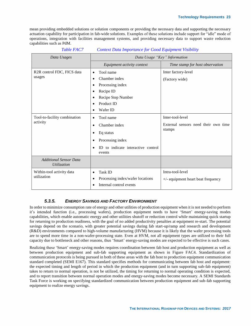
Technology Requirements 23
THE INTERNATIONAL ROADMAP FOR DEVICES AND SYSTEMS: 2017
mean providing embedded solutions or solution components or providing the necessary data and supporting the necessary
actuation capability for participation in fab-wide solutions. Examples of these solutions include support for “idle” mode of
operations, integration with facilities management systems, and providing necessary data to support waste reduction
capabilities such as PdM.
Table FAC7 Context Data Importance for Good Equipment Visibility
Data Usages Data Usage “Key” Information
Equipment activity context Time stamp for host observation
R2R control FDC, FICS data
usages • Tool name
• Chamber index
• Processing index
• Recipe ID
• Recipe Step Number
• Product ID
• Wafer ID
Inter factory-level
(Factory wide)
Tool-to-facility combination
activity • Tool name Inter-tool-level
External sensors need their own time
stamps • Chamber index
• Eq status
• Processing index
• ID to indicate interactive control
events
Additional Sensor Data
Utilization
Within-tool activity data
utilization • Task ID
• Processing index/wafer locations
• Internal control events
Intra-tool-level
+/- equipment heart beat frequency
5.3.5. ENERGY SAVINGS AND FACTORY ENVIRONMENT
In order to minimize consumption rate of energy and other utilities of production equipment when it is not needed to perform
it’s intended function (i.e., processing wafers), production equipment needs to have ‘Smart’ energy-saving modes
capabilities, which enable automatic energy and other utilities shutoff or reduction control while maintaining quick startup
for returning to production readiness, with the goal of no added productivity penalties at equipment re-start. The potential
savings depend on the scenario, with greater potential savings during fab start-up/ramp and research and development
(R&D) environments compared to high-volume manufacturing (HVM) because it is likely that the wafer processing tools
are to spend more time in a non-wafer-processing state. Even at HVM, not all equipment types are utilized to their full
capacity due to bottleneck and other reasons, thus ‘Smart’ energy-saving modes are expected to be effective is such cases.
Realizing these ‘Smart’ energy-saving modes requires coordination between fab host and production equipment as well as
between production equipment and sub-fab supporting equipment as shown in Figure FAC4. Standardization of
communication protocols is being pursued in both of these areas with the fab host to production equipment communication
standard completed (SEMI E167). This standard specifies methods for communicating between fab host and equipment:
the expected timing and length of period in which the production equipment (and in turn supporting sub-fab equipment)
takes to return to normal operation, is not be utilized, the timing for returning to normal operating condition is expected,
and to report transition between normal operation modes and energy-saving modes become necessary. A SEMI Standards
Task Force is working on specifying standardized communication between production equipment and sub-fab supporting
equipment to realize energy savings.
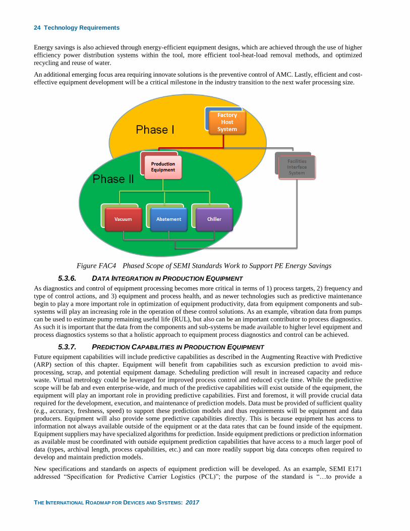
24 Technology Requirements
THE INTERNATIONAL ROADMAP FOR DEVICES AND SYSTEMS: 2017
Energy savings is also achieved through energy-efficient equipment designs, which are achieved through the use of higher
efficiency power distribution systems within the tool, more efficient tool-heat-load removal methods, and optimized
recycling and reuse of water.
An additional emerging focus area requiring innovate solutions is the preventive control of AMC. Lastly, efficient and cost-
effective equipment development will be a critical milestone in the industry transition to the next wafer processing size.
Figure FAC4 Phased Scope of SEMI Standards Work to Support PE Energy Savings
5.3.6. DATA INTEGRATION IN PRODUCTION EQUIPMENT
As diagnostics and control of equipment processing becomes more critical in terms of 1) process targets, 2) frequency and
type of control actions, and 3) equipment and process health, and as newer technologies such as predictive maintenance
begin to play a more important role in optimization of equipment productivity, data from equipment components and sub-
systems will play an increasing role in the operation of these control solutions. As an example, vibration data from pumps
can be used to estimate pump remaining useful life (RUL), but also can be an important contributor to process diagnostics.
As such it is important that the data from the components and sub-systems be made available to higher level equipment and
process diagnostics systems so that a holistic approach to equipment process diagnostics and control can be achieved.
5.3.7. PREDICTION CAPABILITIES IN PRODUCTION EQUIPMENT
Future equipment capabilities will include predictive capabilities as described in the Augmenting Reactive with Predictive
(ARP) section of this chapter. Equipment will benefit from capabilities such as excursion prediction to avoid mis-
processing, scrap, and potential equipment damage. Scheduling prediction will result in increased capacity and reduce
waste. Virtual metrology could be leveraged for improved process control and reduced cycle time. While the predictive
scope will be fab and even enterprise-wide, and much of the predictive capabilities will exist outside of the equipment, the
equipment will play an important role in providing predictive capabilities. First and foremost, it will provide crucial data
required for the development, execution, and maintenance of prediction models. Data must be provided of sufficient quality
(e.g., accuracy, freshness, speed) to support these prediction models and thus requirements will be equipment and data
producers. Equipment will also provide some predictive capabilities directly. This is because equipment has access to
information not always available outside of the equipment or at the data rates that can be found inside of the equipment.
Equipment suppliers may have specialized algorithms for prediction. Inside equipment predictions or prediction information
as available must be coordinated with outside equipment prediction capabilities that have access to a much larger pool of
data (types, archival length, process capabilities, etc.) and can more readily support big data concepts often required to
develop and maintain prediction models.
New specifications and standards on aspects of equipment prediction will be developed. As an example, SEMI E171
addressed “Specification for Predictive Carrier Logistics (PCL)”; the purpose of the standard is “…to provide a
Technology Requirements 25
THE INTERNATIONAL ROADMAP FOR DEVICES AND SYSTEMS: 2017
communication scheme for exchanges of carrier logistics related information, especially predictive information, between
equipment and the factory system in order to support seamless cascading of carriers for continuous processing of equipment
in microelectronics fabrication systems or similar ones”.
Further detail on inside-equipment prediction systems and their role in the prediction vision can be found in the
Augmenting Reactive with Predictive and Big Data sections of this chapter.
Table FAC8 Production Equipment Technology Requirements
5.4. MATERIAL HANDLING SYSTEMS NEEDS
5.4.1. OVERALL
Ergonomic and safety issues coupled with the need for efficient and rapid material transport are the major drivers in defining
material handling systems for the 300 mm wafer generation and beyond. AMHS must have acceptable return on investment
(ROI) and must interface directly with all inline (i.e., used in normal process flow) production and metrology equipment.
AMHS must deliver material in a timely fashion to support critical equipment in order to minimize wait time waste.
Furthermore, the material handling system needs to be designed so that it can accommodate the extendibility, flexibility,
and scalability demands on the factory with minimum down time.
The AMHS Technology Requirements Table FAC-9 is based on the premise that as demands on the material handling
system continue to increase while supporting fab operations with decreased down time and reduced lot wait-time waste on
bottleneck equipment. In order to achieve the requirements, AMHS may be composed of interoperable sub-systems from
multiple (best of breed) suppliers.
Solutions to provide better utilization of floor space through optimization of tools layout of the factory, integration of
process and metrology equipment, etc. must be developed. It is also necessary to investigate the potential impact of
increasingly larger factory sizes that require AMHS transport between multiple buildings and floors.
For efficient production, there will be a need to integrate WIP scheduling and dispatching systems with storage and transport
systems for the goal of reducing wait time waste (WTW). This is especially true as scheduling and dispatching systems
become predictive. For example, correctly predicting/scheduling pending and completed jobs on tools enables the
prepositioning of carries and transport close to tools when jobs on tools are finished.
The potential impact of high-mix operations and smaller lot sizes must be investigated. The tradeoff between lot size and
MPH increase also needs to be evaluated. The adoption of automated reticle transport systems by IC makers will depend
on the business model for the factory. Potential solutions for reticle transport systems must not negatively impact the
lithography equipment's footprint, run rate, and ease of installation or de-installation.
5.4.2. 450 MM
Investigation and evaluation of the 450 mm physical interface and carriers (PIC) have been developed. The AMHS design
may have to be revisited along with investigation into the wafer transport/storage (near tool) capabilities (i.e., EFEM, shared
EFEM, on-tool storage). Other items that will impact AMHS design will be the 450 mm factory size, factory layout, AMC
needs and factory throughput and cycle time requirements.
Table FAC9 Material Handling Systems Technology Requirements
5.5. FACTORY INFORMATION AND CONTROL SYSTEMS NEEDS
5.5.1. SCOPE
The scope of FICS includes computer hardware and software, manufacturing execution, decision support systems, factory
scheduling, control of equipment and material handling systems, and process control. FICS serves as an essential
infrastructure and technology enabler to a number of critical functional areas addressed by the IRDS—including yield,
factory operations, production equipment, and material handling control and management.
5.5.2. IMPROVE FACTORY EFFECTIVENESS
Factories must be able to adjust schedules and dispatching schemes rapidly to quickly respond to unexpected equipment
downs or product scrap to maximize productivity and maintain target production rates and production times of high priority
(hot) lots as well as the production lots. This calls for optimization and prediction models that include predicting impacts
26 Technology Requirements
THE INTERNATIONAL ROADMAP FOR DEVICES AND SYSTEMS: 2017
of operational or configuration changes to other FICS applications. The objective is to make the best choice of what to
process looking beyond the boundaries of a single tool or cluster tool. With a global view of factory activity, the scheduling
component can make decisions beyond a small area in the factory. The effect will be greater factory utilization, higher
throughput, and reduced cycle time variability. Integration of FICS applications with business-level software systems
provides accurate factory floor data for supply management, and improved product tracking. Potential solutions will require
the standardization of technologies (e.g., Simple Object Access Protocol, Service Oriented Architecture Protocol (SOAP)
and Extensible Markup Language (XML) and web services) that enable this level of integration.
5.5.3. IMPROVE FACTORY YIELD AND MINIMIZE WASTE
Yield improvement and waste minimization will rely heavily on FICS solutions. Process control systems (PCS) which
utilize APC technologies including R2R control, fault detection (FD), fault classification (FC), fault prediction (FP) and
statistical process control (SPC) will become more pervasive and an integral part of FICS solutions. SEMI standard E133
should be leveraged for definitions, identifying capabilities and possible identifying interface requirements for PCS
solutions. SEMI standard E126 should be leveraged for specifying R2R control capabilities specific to a process type.
Highly integrated PCS solutions will enable yield and process capability improvement, while reducing cycle time, ramp-
up (re)qualification time, scheduled and unscheduled downtime, non-product wafers, scrap, and rework levels. R2R control
at the wafer and increasingly the sub-wafer level will utilize virtual metrology and efficiently adapt to product changes, and
maintenance events. Module and cross-module control solutions such as litho-to-etch CD control will become more
prominent and R2R control capabilities will be linked to fab-level parameter targets such as yield, throughput, and electrical
characteristics.
Fault detection systems will continue to trigger at recipe step boundaries but as equipment data sampling rates increase real-
time alarming will see greater utilization and also provide input for virtual metrology systems tied to R2R control. Fault
classification and fault prediction can reduce problem resolution time and the severity of process excursions, but widespread
use will evolve slowly due to technology and standards hurdles. Chamber variance tracking and reporting will become an
increasingly important tool for identifying yield and throughput issues, with APC assisted chamber variance control
eventually taking the place of variance reporting. SPC is a mature technology with its current use rate and domain space
continuing. Over the longer term, PCS solutions will leverage virtual metrology and other technologies to provide for real-
time yield prediction with feedback into FICS for improved scheduling/dispatch, process control, and maintenance
management that is better tied to productivity and waste objectives.
The FICS will provide collaborative integration between APC, manufacturing execution system (MES), equipment
performance tracking (EPT), factory scheduler/dispatcher, maintenance management, and AMHS. This level of system
integration is required to ensure delivery of the right material, lot, and wafers at the right time at the right locations
maximizing equipment utilization. It will be enabled by event-driven, reconfigurable supervisory control capabilities at the
heart of the FICS; common data warehouse and data models; adoption of Interface ‘B’ and associated standards for
application integration; proliferation of networks for control diagnostics, and safety signals across the fab.
5.5.4. DATA UTILIZATION
Increasing levels of collaborative integration and exchange of data between key FICS system components, smaller lot sizes,
and tighter process windows will lead to increased message and data load that must be managed by the FICS. Production
equipment will be providing increased volumes of data: sensor data required for fault detection, advanced process control
data, and tool performance data; including critical equipment actuators such as mass flow, pressure, and temperature
controllers. The FICS must be scalable to accommodate increasing data rates and manage the collection, storage, and
retrieval of this increase in data collection. While distributed systems are not novel; FICS architectures will increasingly
distribute data and applications below the factory level. Distributed data and applications will decrease factory bandwidth
competition and enhance the FICS ability to filter through large quantities of data, to identify the specific set of information
required to make decisions for factory operation and business-level decisions. Additional information big data issues of this
type are discussed in the Big Date section.
Achieving these FICS requirements will necessitate alignment to industry standards for data acquisition, data interchange,
and recipe management. Specific tool, supplier, or manufacturing-defined proprietary interfaces will increase
implementation time and cost to both the IC manufacturer and the FICS supplier. Time to develop these new standards must
be decreased, through collaboration between IC makers, equipment suppliers, and FICS suppliers. Ultimately the standards-
compliant applications will reduce time and cost of integration, allowing IC makers and suppliers to focus on improved
capabilities rather than customized integration. This will decrease the risk of new applications integration into an existing
factory system.
Technology Requirements 27
THE INTERNATIONAL ROADMAP FOR DEVICES AND SYSTEMS: 2017
5.5.5. HIGHLY RELIABLE, HIGH PERFORMANCE SYSTEMS
The increasing reliance of the factory on the FICS infrastructure will continue to drive increased factory system complexity.
There will be increased attention to maintaining the gains to overall factory system availability and to further decreasing
the occurrence of full fab downtime incidents caused by a failure of a single, mission critical application as shown in the
FICS Technology Requirements Table FAC-10. Mission-critical FICS components, both software and hardware, must
provide fault tolerant solutions that eliminate unscheduled factory system failures as well as scheduled downtime to install
or upgrade. Potential solutions include software applications and databases that are capable of dynamic upgrades; software
applications that can monitor health of factory systems and that can induce load-balancing, and fault tolerant computer
systems with transparent hardware switching for failovers.
Cyber security continues to remain a high priority from the factory operations perspective. Cyber security guidelines were
first published by ISMI in March 2005 documenting available methods for cyber security. The security focus is also on
protecting IP within the equipment. Microelectronics equipment is now well integrated into the FICS infrastructure with
engineers and technicians. Ensuring IP protection is critical to overall financial success in an environment where there is a
significant amount of operations-level overlap.
Table FAC10 Factory Information and Control Systems Technology Requirements
5.6. FACILITIES NEEDS
5.6.1. SCOPE AND FACILITY MISSION
Facilities include the overall physical buildings, cleanroom and facility infrastructure systems, including tool hook up. The
IRDS Facilities scope does not include adjacent general office spaces and corporate functional areas. It is important to note
that the following requirements will affect the facility and support facility infrastructure system with respect to their
complexity and costs:
• production equipment
• manufacturing goals
• management philosophies
• environmental, safety, and health (ESH) goals
• building codes and standards
• defect-reduction and wafer cost reduction targets
• disruptive manufacturing technology migration
5.6.2. DEMAND ON FACILITIES SERVICES INCREASES
The industry continues to demand facilities that are increasingly flexible, environmentally benign, extendable and reliable,
services that come online more quickly, and are more cost-effective. However, production equipment requirements, ESH/S
compliance and factory operational flexibility continue to drive increased facility capital and operating costs. Production
and support equipment are becoming more complex, larger, and heavier, thereby driving the need for a continuous increase
in factory size and tool packing density.
New and different process steps are increasing the growth of the cleanroom’s size faster than the increases in factory
production output. A focus on environmental issues such as carbon footprint reduction added constraints on the facilities
operational objective function. Consequently, the increasing size and complexity of the factory, the production equipment
and material handling systems, as well as the pressure to reduce time-to-market and facility costs, will make compliance
with many of the current requirements a greater challenge. Better coordination among the items listed below are necessary
to achieve these goals, improve system and space utilization, and control facility capital and operating costs:
• production equipment operation
• maintenance
• environmental requirements
• facility infrastructure system design
• handling new process chemicals throughout facility (source supply to exhaust treatment)
• installed utility capacities vs. load
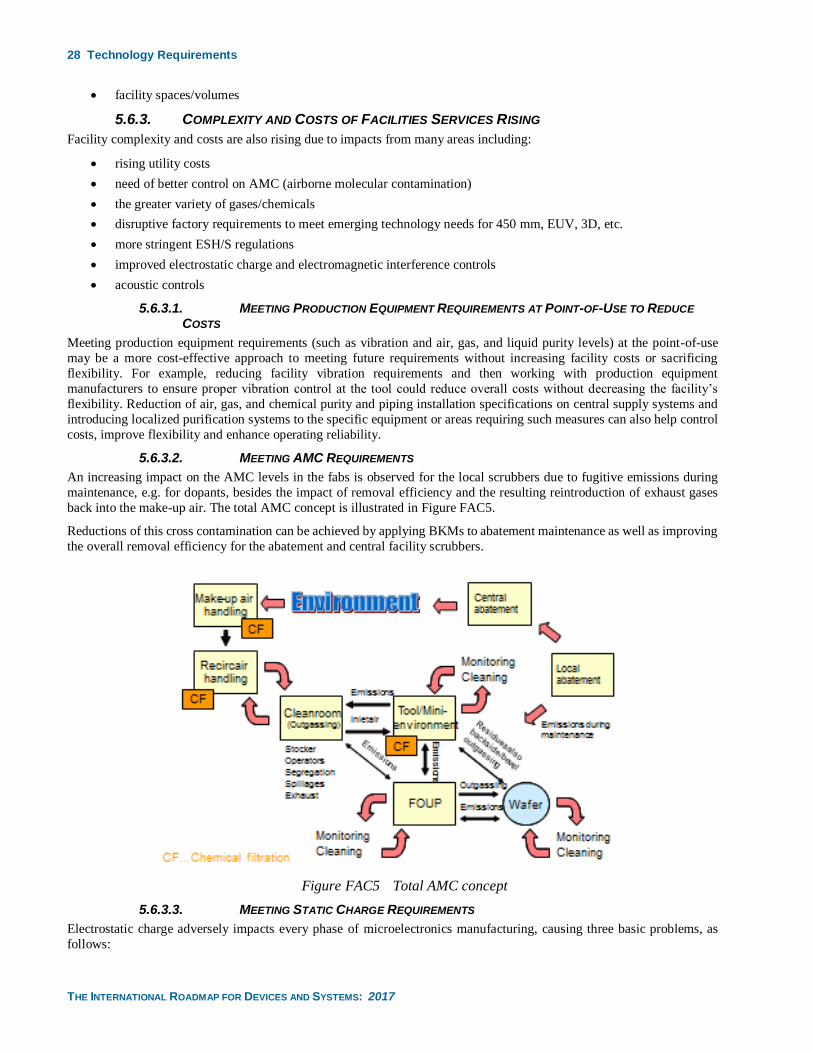
28 Technology Requirements
THE INTERNATIONAL ROADMAP FOR DEVICES AND SYSTEMS: 2017
• facility spaces/volumes
5.6.3. COMPLEXITY AND COSTS OF FACILITIES SERVICES RISING
Facility complexity and costs are also rising due to impacts from many areas including:
• rising utility costs
• need of better control on AMC (airborne molecular contamination)
• the greater variety of gases/chemicals
• disruptive factory requirements to meet emerging technology needs for 450 mm, EUV, 3D, etc.
• more stringent ESH/S regulations
• improved electrostatic charge and electromagnetic interference controls
• acoustic controls
5.6.3.1. MEETING PRODUCTION EQUIPMENT REQUIREMENTS AT POINT-OF-USE TO REDUCE
COSTS
Meeting production equipment requirements (such as vibration and air, gas, and liquid purity levels) at the point-of-use
may be a more cost-effective approach to meeting future requirements without increasing facility costs or sacrificing
flexibility. For example, reducing facility vibration requirements and then working with production equipment
manufacturers to ensure proper vibration control at the tool could reduce overall costs without decreasing the facility’s
flexibility. Reduction of air, gas, and chemical purity and piping installation specifications on central supply systems and
introducing localized purification systems to the specific equipment or areas requiring such measures can also help control
costs, improve flexibility and enhance operating reliability.
5.6.3.2. MEETING AMC REQUIREMENTS
An increasing impact on the AMC levels in the fabs is observed for the local scrubbers due to fugitive emissions during
maintenance, e.g. for dopants, besides the impact of removal efficiency and the resulting reintroduction of exhaust gases
back into the make-up air. The total AMC concept is illustrated in Figure FAC5.
Reductions of this cross contamination can be achieved by applying BKMs to abatement maintenance as well as improving
the overall removal efficiency for the abatement and central facility scrubbers.
Figure FAC5 Total AMC concept
5.6.3.3. MEETING STATIC CHARGE REQUIREMENTS
Electrostatic charge adversely impacts every phase of microelectronics manufacturing, causing three basic problems, as
follows:

Technology Requirements 29
THE INTERNATIONAL ROADMAP FOR DEVICES AND SYSTEMS: 2017
1. Electrostatic attracted (ESA) contamination increases as particle size decreases, making defect density targets more
difficult to attain. Electrostatic attraction of particles to masks will become a more serious problem if future
lithography methods eliminate the pellicle used to keep particles away from the mask focal plane.
2. Electrostatic discharge (ESD) causes damage to both devices and photo-masks. Shrinking device feature size
means less energy is required in an ESD event to cause device or mask damage. Increased device operating speed
has limited the effectiveness of on-chip ESD protection structures and increased device sensitivity to ESD damage.
3. Equipment malfunctions due to ESD-related electromagnetic interference (EMI) reduce OEE and have become
more frequent as equipment microprocessor operating speeds increase.
Electrostatic discharge (ESD) sensitivity trends will have larger impact on manufacturing process yields as the device
feature size decreases. Companies will need to increase their efforts to verify that the installed ESD controls are capable of
handling these devices and to make any necessary improvement in ESD control methods. This could include changes in the
ESD control item limits, changes in the frequency of compliance verification, and other forms of ESD monitoring, such as
ESD event detection.
It should be noted that progressive reticle pattern degradation in photomasks can be caused by electric fields that are very
much weaker than those that induce ESD damage. This damage phenomenon is called EFM (Electric Field Induced
Migration). Transient or rapidly changing electric fields that are not strong enough to induce ESD are particularly
problematic because they will cause cumulative EFM. This may escape detection until defective devices are being produced.
5.6.3.4. GUIDANCE ON RETICLE ELECTROSTATIC PROTECTION
When controlling ESD was the primary objective, limiting the field strength to which a reticle could be exposed was a valid
countermeasure. But it is now known that other damage mechanisms operate several orders of magnitude below the ESD
threshold and they are capable of causing even more significant losses in microelectronics production than reticle ESD.
They operate cumulatively every time the field passing through a reticle changes, so every change in the field experienced
by a reticle, even at a very low level, has the potential to add to the degradation.
This leads to the deduction that it is no longer appropriate to address the electrostatic risk to a reticle in the IRDS by simply
tabulating a maximum recommended field strength year by year, as has been customary for ESD prevention. The number
of reticle moves taking place while any electric field may be present and the degree of a reticle’s exposure to transient or
oscillating fields may be more significant risk factors. The sensitivity of reticles to these difficult-to-quantify risk factors
will, however, inevitably increase over time.
For this reason, the recommendation for reducing reticle electrostatic damage is now to minimize a reticle's exposure to any
strength of electric field, not to move reticles while any electric field may be present, and especially to prevent transient
and oscillating fields from reaching a reticle. Achieving this will require the increased adoption of metallic shielding to
keep electric fields and especially fast field transients away from reticles. Measures that were developed to address the ESD
risk, but which do not protect reticles against these risks, such as equipotential bonding (grounding) and the use of static
dissipative materials for making reticle boxes, may need to be replaced with more protective approaches. Guidance about
this is provided in SEMI Standard E163.
5.6.3.5. MEETING ELECTROMAGNETIC INTERFERENCE CONTROL REQUIREMENTS
It has been known for many years that Electromagnetic Interference (EMI) (see the standard SEMI E33 for definition)12
causes a variety of problems for microelectronics manufacturing, including, but not limited to, equipment lockup and
malfunction, sensor misreading, metrology errors, sensitive component damage and others. There are many sources of EMI
in microelectronics environment that include electromagnetic emission from ESD, operation of equipment, especially high-
energy tools, motors and actuators, wireless communication and alike. Co-location of sensitive equipment with high-energy
tools, cabling, ground problems, improper maintenance of equipment and others further aggravate EMI problems.
In the past these influences were limited to applications in research. Now, due to ongoing shrinking of structures and the
explosive increase of applications using wireless communication techniques, the influence of EMI effects in
microelectronics manufacturing Fabs becomes more pronounced, particularly in areas where uncontrolled electromagnetic
fields are a very sensitive concern as in SEM/TEM, e-beam and metrology tools to perform its intended functions.
Therefore, understanding EMI phenomena, its impacts, and how to mitigate it in a cost-effective fashion become more
important as process technology progresses into the future. Currently EMI is not well understood by the end user and thus
leads to misdiagnosed problems and misapplied EMI mitigation/controls. This needs to be addressed at a global level to
prepare for what is expected to be more electromagnetic-related impacts in the future.
30 Technology Requirements
THE INTERNATIONAL ROADMAP FOR DEVICES AND SYSTEMS: 2017
To control and reduce the negative impact of EMI on wafers, materials and equipment, more comprehensive
studies, advanced methods and measurement tools are needed.
5.6.4. MICROELECTRONICS INDUSTRY FUTURE CHANGES AND REQUIREMENTS
Despite the continuous device feature size shrinkage and increase of process complexity in process technology according
to Moore’s Law, the drive towards the reduction in manufacturing cost will result in the introduction of larger wafer sizes,
such as 450 mm wafers. Such a change will also have implications on the design and construction of a wafer manufacturing
facility due to increases in overall size, height, and weight of process equipment, their utility consumption, and other
process-driven facility requirements such as AMC, EMI, ESD and acoustic controls.
With more production support equipment placed in the sub-fab, a utility sub-fab may be required to house additional
equipment. For example, the addition of local purification and reclaim systems at the support equipment level will require
more sub-fab area. These challenges will continue to drive the need for further facility technology development in such
areas as:
• PFC abatement
• structural design
• AMHS facility integration
• chemical delivery facility integration
• Ultra-pure Water (UPW) delivery
• energy efficiency
• communication challenges (energy, water, waste, emissions, management) infrastructure
• Airborne Molecular Contamination (AMC) control
• EMI/ESD controls
• microelectronics materials ESH/S management
• Energetics Materials ESH/S management and facility consideration
Such considerations must also be evaluated in the case of a planned conversion of an existing wafer manufacturing facility
to the next wafer size.
5.6.5. RESOURCE CONSERVATION CONSIDERATIONS
The need to reduce resource consumption is an area that requires greater attention. This will necessitate the integration of
new technologies in the design and construction of facilities as well as different operational strategies.
For example, reduction of the cleanliness within the manufacturing space to ISO Class 7 could reduce the recirculation air
volume requirements. (Consider widening temperature, humidity, and pressurization requirements) This would have a
ripple effect on the exhaust and make-up air systems; which would lead to reduction in power consumption. Process
equipment idle and sleep modes can also reduce energy consumption during non-processing times. Heat recovery systems
can reuse heat otherwise dissipated to the atmosphere. Using more process cooling water will further reduce the amount of
recirculation air required to remove heat generated by the process equipment.
These are just some examples requiring further consideration. Green technologies must also be considered for integration
into the design and construction of future facilities. For example, by incorporating concepts such as those outlined by the
US Green Building Council’s LEED program into the design of the facility, energy and water conservation strategies would
need to be more widely adopted.
With the new technologies and the introduction of mega fabs the energy and water footprints become significant when
considering the local available infrastructure. Seasonal draughts and geography specific water availability in some advanced
microelectronics fab locations further exacerbate the concern.
The infrastructure itself will be a serious limiting factor for many locations both with regard to water and power availability,
quality and cost. It will be become an increasingly important site selection constraint for new fab construction or expansions
of the existing facilities.
Technology development needed to be driven both for energy and water consumption to reduce the external utility footprint.
But this task is much more complex than it looks at the first glance.
Technology Requirements 31
THE INTERNATIONAL ROADMAP FOR DEVICES AND SYSTEMS: 2017
1. Water recycling and reuse will require substantial investment in either complex segregation of the industrial
wastewater streams with subsequent treatment or sophisticated end-of-pipe solutions.
2. Increased water recycling at same consumption level will reduce the external water supply needs but will increase
energy and potentially also chemical consumption.
3. Water reuse may also increase parameters in the site outfall posing the risk of environmental compliance
a. Chemical consumption has dramatically increased in latest technology generations. Unless the chemical
consumption is reduced dramatically, or the chemical waste segregation is not improved, increased water
recycling excursions in waste water concentration and issues environmental compliance and external water
reuse will be the result.
4. Process requirements such as lithography needs (EUV or multiple patterning) as well as the need to reduce F-GHG
and N2O emissions will drive power consumption even further. Increased energy consumption adds cooling load,
which results in higher water evaporation in the cooling towers. The effect is similar to recycling, increasing
concentrations of the contaminants in the site effluent.
More development is needed to address these complex and interconnected issues.
5.6.6. INDUSTRY COLLABORATION FOR FACILITIES
To reduce the time from groundbreaking to the first full loop wafer out, a paradigm shift in the way facilities are designed
and constructed will be required to meet the following demands
• the fabrication process and the production equipment will increase in complexity
• factory operations will seek more flexibility
• global codes, standards, and regulations will increase in variability
This shift entails complete integration of the IC manufacturer, the factory designers/builders and the production equipment
manufacturers into the entire project team. At a minimum, the project team must be assembled at an early stage with process
engineers, manufacturing engineers, facility engineers, design consultants, construction contractors, ESH/S personnel, as
well as manufacturers of process equipment and facility components.
Development of building information models, standardized design concepts, generic fab models, and off-site fabrication
will be required to meet desired cost reduction goals to deliver a facility capable of meeting both current and future process
technology requirements. Challenging the production equipment suppliers and factory design teams to develop and conform
to a standardized utility infrastructure will also help control capital cost and reduce time-to-market.
Development of sustainability concepts for factory construction and operation will improve resource usage and reduce the
environmental impact, for example:
• Production equipment installation costs and time continue to be driven higher by increasing gas, chemical and
utility connections, energy conservation methodologies, and process-driven facility and ESH/S compliance
requirements. Earlier awareness of new production equipment designs, standardization of production equipment
connections, and the materials of construction, and the availability of measured utility consumption flow data in a
standardized database system would allow for appropriate construction of the base build with an emphasis on
“Design for Facilities”.
• Construction costs can be substantially reduced by lowering exhaust /make-up air requirements, raising non-
critical process equipment’s cooling water inlet temperatures to a level where no central chiller plant is required
for this equipment and using higher voltage power for production equipment as much as feasible.
• Operating costs can be reduced by innovative reuse and recycling concepts for Ultra-Pure Water (UPW),
implementing equipment “sleep” mode during idle periods, raising process cooling water temperatures.
Although reliability of facility infrastructure systems is currently sufficient to support manufacturing, much of it has been
achieved through costly redundancy. Improvements are still required in the design and operation of individual electrical,
mechanical, chemical delivery, and telecommunications and facility control components and systems to reduce
manufacturing interruptions. Collaboration with facility component manufacturers and equipment suppliers may modify
the N+1 philosophy for redundancy, and positively affect costs without sacrificing reliability.
5.6.7. 450 MM CONSIDERATIONS
Any significant change in the production equipment, both for post-CMOS or for the next generation wafer size, such as
new chemistries, the wafer environment or handling requirements (nitrogen or vacuum atmospheres, transition of an
32 Technology Requirements
THE INTERNATIONAL ROADMAP FOR DEVICES AND SYSTEMS: 2017
equipment type from batch processing to single wafer manufacturing, etc.), will have an impact on future factory
requirements. The high cost of a 450 mm Fab will increase the capital investment risk and drive more focus on loss
prevention mitigation such as increased fire protection, more robust building materials and MFL (maximum foreseeable
loss) separation walls within the Fab.
The table below outlines facilities technology requirements.
Table FAC11 Facilities Technology Requirements
5.7. AUGMENTING REACTIVE WITH PREDICTIVE NEEDS
5.7.1. SCOPE
The scope of Augmenting Reactive with Predictive (ARP) is all FI technologies that can have a predictive component. This
section addresses the challenges and solutions associated with the augmenting of existing reactive technologies with
predictive technologies while retaining the reactive capabilities. These predictive technologies include, but are not limited
to, Predictive Maintenance (PdM), Equipment Health Monitoring (EHM), Fault Prediction (FP), Virtual Metrology (VM),
predictive scheduling, yield prediction and augmenting predictive capabilities of the factory through simulation and
emulation. The following definitions are used for purposes of discussion in this document; these definitions should be
replaced by standardized definitions as they become available in the industry.
• Predictive Maintenance (PdM) – Also referred to previously as Predictive and Preventative Maintenance (PPM)
and Prognostic Health Management, PdM is the technology of utilizing process and equipment state information
to predict when a tool or a particular component in a tool might need maintenance, and then utilizing this prediction
as information to improve maintenance procedures. This could mean predicting and avoiding unplanned
downtimes and/or relaxing un-planned downtime schedules by replacing schedules with predictions. PdM
solutions as defined herein address the entire maintenance cycle, from predicting maintenance through addressing
recovery from maintenance events towards returning to production. Note that PdM for equipment or a particular
equipment component could be managed at the equipment level or fab level, while other PdM activities require
fab level management.
• Equipment Health Monitoring (EHM) – The technology of monitoring tool parameters to assess the tool health as
a function of deviation from normal behavior. EHM is not necessarily predictive in nature but is often a component
of predictive systems.
• Virtual Metrology (VM) – (standardized definition from SEMI E133) is the technology of prediction of post
process metrology variables (either measurable or nonmeasurable) using process and wafer state information that
could include upstream metrology and/or sensor data.
• Fault Prediction (FP) – (standardized definition from SEMI E133) is the technique of monitoring and analyzing
variations in process data to predict anomalies.
• Predictive Scheduling – Is the technology of utilizing current and projected future information on tool and factory
state, capabilities, WIP, schedule, dispatch and orders to predict and improve scheduling of a system (tool, group
of tools, fab, etc.).
• Yield Prediction – Is the technology of monitoring information across the fab (e.g., tool and metrology) to predict
process or end of line yield.
5.7.2. PREDICTION VISION
The prediction vision is a state of fab operations where 1) yield and throughput prediction is an integral part of factory
operation optimization; and 2) real-time simulation of all fab operations occurs as an extension of existing system with
dynamic updating of simulation models—this concept is often referred to as “digital twin” [11,3]. The prediction vision
generally is the same for 300 mm and 450 mm facilities and full implementation of the vision is expected to become a
requirement for remaining cost competitive in both facility types. Prediction capabilities will likely be required first and
have more impact on certain tool types such as bottleneck tools.
Achievement of this vision will place a number of requirements on the roadmap for all prediction technologies.
1. Roadmaps for each of the predictive technologies must be structured to support their eventual merging in terms of
sharing data and capabilities. This is because the prediction vision can only be achieved through the cost-effective
collaboration of all prediction technologies.
Technology Requirements 33
THE INTERNATIONAL ROADMAP FOR DEVICES AND SYSTEMS: 2017
2. Prediction technologies should be structured wherever possible to be strictly value add. In other words, there must
be a clear understanding that the value provided by the successes of the prediction engine (e.g., correct predictions)
is larger than the cost associated with the failure of the prediction engine (e.g., missed or false predictions). This
in-turn requires that prediction solutions provide not only predictions, but indications of quality of predictions, and
prediction solution implementation must incorporate quality of prediction information into solution design and
optimization.
3. Prediction technologies must be structured to augment rather than strictly replace their reactive counterparts. This
is because prediction will never be 100% accurate or 100% comprehensive. The reactive capabilities should
complement the predictive capabilities by providing support to fab operations where prediction fails or is not
implemented, and by providing input to future prediction capabilities such as predictive models.
4. Predictions systems will include aspects of prediction from equipment. Equipment has access to information not
always available outside of the equipment or at the data rates that can be found inside of the equipment. Inside
equipment predictions or prediction information as available must be coordinated with outside equipment
prediction capabilities that have access to a much larger pool of data (types, archival length, process capabilities,
etc.). Further detail on inside-equipment prediction systems can be found in the Production Equipment section of
this chapter.
5. Data quality of systems must be improved to better support predictive capabilities. Data quality of existing systems
is a function of the requirements for these systems. Because these systems are (today) generally not designed with
prediction in mind, they don’t always have the necessary data quality to support cost-effective prediction
capabilities. Examples include inaccurate human-entered and missing context data in maintenance management
systems, and insufficient archiving of data necessary to realize robust predictive models. The data quality issue is
especially true of maintenance management systems (e.g., with human data entry). A roadmap for improvement
of data quality of these systems to make them “prediction ready” is needed. Data quality guidelines and standards
such as SEMI E151 and E160 should be leveraged.
6. Prediction solutions must be robust to support long-term application. The required accuracy of prediction solutions
is application dependent. Knowledge of prediction accuracy (the second requirement) is thus necessary for
determining robustness of the prediction engine. The prediction engine may need to be updated to support changes
in the application environment. Thus, a roadmap for successful application of prediction solutions necessarily
requires that these prediction solutions be robust to continuously adapt to their application environment. As part
of this requirement, methods will have to be developed to maintain robustness as prediction quality continually
improves and thus less “mistakes” (such as false positives or missed events) are available to update the predictor;
for example, if the predictor results in zero unscheduled downtime, it may be due to high accuracy of the predictor
or an overly conservative prediction.
7. Prediction solutions must provide predictions of required accuracy in a timely manner with respect to the
application for which they are being used. This means that the prediction engine can be constrained by a maximum
time for prediction (e.g., response time, or event occurrence), a required accuracy for prediction, or some
combination of time and accuracy. Prediction solutions will have to be designed to support configuration to these
constraints, depending on the application.
The roadmap for application of the prediction technologies varies among tool types. Predictive scheduling will initially
focus on bottleneck tool types such as lithography where the benefit potential is high, however, longer term it will result in
coordinated predictive scheduling of all tool types. EHM can be applied to any tool type where FD data collection is
available, so the focus will be guided by need for health monitoring. VM focus has initially been on tool types where higher
quality models can be realized, such as CVD and etch. Initial VM is focused on its use as an aid in excursion detection
(ExD). This will be expanded to more widespread use to support “smart metrology” (SM), where real and virtual metrology
work together to maximize the effectiveness of metrology given cycle time optimization requirements. Longer term VM
will be used to augment process control, e.g., converting lot-to-lot control to W2W control, by providing predicted
metrology values to supplement both pre and post process metrology. Additionally, in the longer term, fab-wide approaches
to VM will be leveraged and prediction quality will be incorporated into VM application optimization. PdM will initially
focus on maintenance events that are costly, occur more frequently (so more events are available for developing/maintaining
models), and generate higher quality models; as with VM, longer term PdM will incorporate prediction quality in the
decision process allowing for more widespread application and adoption. Yield prediction will likely leverage many of the
same prediction technologies used for VM but will require coordination across the fab and improved data quality. As such,
this technology will likely not become widespread until successes with VM and PdM become more widespread. Initially
the focus will be on yield excursion detection (YEx) with root cause analysis via data mining (DM). Real-time simulation
of fab operations as an extension of existing system (i.e., digital twin) is a long-term vision that will necessarily require the
34 Technology Requirements
THE INTERNATIONAL ROADMAP FOR DEVICES AND SYSTEMS: 2017
successful implementation of the individual prediction capabilities followed by their integration on a common prediction
platform.
5.7.3. TECHNOLOGY REQUIREMENTS
Achievement of the prediction vision places requirements in the individual prediction technologies as well as the
comprehensive prediction strategy.
Table FAC12 Augmenting Reactive with Predictive (ARP) Technology Requirements
5.8. BIG DATA NEEDS
5.8.1. INTRODUCTION
To improve factory operations and traceability companies must invest in solutions to effectively manage their data growth.
Data generation, storage and usage have increased in the factory because of the improvements of microelectronics
equipment computer interfaces that provide higher rates for data collection and additional equipment parameter data
availability. In addition to the increase of equipment generated data, manufacturing data analysis requires more complex
data integration because the needed data comes from multiple sources and databases. Traditional database and file systems
processing capabilities are being exceeded by transactional volumes, velocity responsiveness, quantity, variety, and veracity
of data created. This explosion of data growth in manufacturing has created a set of requirements which are commonly
referred to as “Big Data” (BD). As a result, there are significant efforts across industry to define big data and the big data
problem. A consolidated effort is being headed by NIST (National Institute of Standards and Technology) [12]. Big data is
characterized by an increase in: data volume, velocity of generation (as well as variability in collection and storage rates),
variety of data sources, difficulty in verifying the veracity, or “quality”, of the data, and difficulty in obtaining maximum
value from the data through efficient analytics and processing. From an information technology perspective, Big data
represents data sets whose size, type, speed of creation, or data quality make them impractical to process and effectively
analyze with traditional database technologies and related tools in a cost- or time-effective way.
5.8.2. SCOPE
The scope of this big data section is to identify the challenges and potential solutions associated with big data attributes of:
volume, velocity, variety, veracity and value in microelectronics manufacturing environment.
5.8.3. TECHNOLOGY REQUIREMENTS
Big data technology requirements can be categorized according to the big data issues identified above, namely volume,
velocity, variety, veracity and value.
Volume
With the increase of data collected per tool and per wafer, storage of large amounts of data (petabytes) places considerable
load and cost on existing infrastructure, such as analyzing, storing, processing and cleansing data. Algorithms to optimize
the storage of data are needed. Data models that enable access of the data in an optimal and reliable way must be developed
and standardized for applications to plug and play.
Velocity
Velocity issues with data include speed of generation, speed of compression as needed for transmission, speed of
transferring, speed for pre-processing for storage, speed of storage and speed of analyzing. The rate of data generation is
exceeding the ability to store it in the underlying systems. For example, sensor networks are able to generate vast data sets
and at rates that exceed the storage capability of traditional SQL databases.
Variety
Merging different data sources and data types is often difficult, time-consuming and results in data quality degradation
(Veracity). For example, wafer image data (from visual inspections) is not easily stored with numeric data types in the same
database table. A factory must make huge volumes of data meaningful to the product flow and process steps such that
multiple applications can take advantage of the data to create meaningful and actionable information.
Veracity
Veracity refers to the accuracy or truthfulness of the data. For example, data store reduction can be accomplished by new
and emerging techniques used to compress data without impacting the quality of the data and ensuring no loss of
information. These tools or applications may not be sufficient or could be limited by the type of application used by the
Technology Requirements 35
THE INTERNATIONAL ROADMAP FOR DEVICES AND SYSTEMS: 2017
factory. Retrieving the compressed data by those applications may also impact the accessibility and quality of potential
predictions from that big data.
Another common issue is using data timestamps from multiple sources to merge data. These timestamps are often
unsynchronized resulting in low data quality of merged data, thus impacting the factory’s ability to used data from multiple
sources reliably. The scope and/or resolution of the data collected from multiple sources and often at different rates further
complicates the merging of data. For example, merging metrology with Fault-Detection Control (FDC) data and
maintenance data provides many unique challenges.
Data that depends on or is created by personnel (i.e., “human entered data”) can often be associated with many data quality
issues such as accuracy, timeliness or freshness, availability and clarity. Challenges arise from merging different types of
data (such as a context data) with continuous tool data-sets. In this area standards may be required to reduce errors created
by humans. Correlation of personnel actions to resolve problems with the process tool would also likely benefit from
standardization with the goal of optimizing the quality of the data.
Value
The cost of big data needs to be balanced with its potential value. Costs include collection, storage, and processing of the
data. This is weighed against the benefits—both quantifiable and unknown. The unknown benefits refer to data that might
be collected with the thought of data exploration and/or future event analysis (the event hasn’t yet happened, but the data
might provide insight into how the event would occur).
To help determine the value of data there are often statistical applications specific to particular groups of data consumers.
For example, factories are often interested in fault detection, condition-based health monitoring and prognostics information
to the factory. These applications can become bottlenecks in their attempt to analyze and provide information in near real
time of high-volume, high-velocity data. Factory specific applications need to provide plug and play means to access the
data or information they generate such that data analysis can be done at different layers and with different types of data.
Applications need easy access to the data, in the right format, for efficient analysis to occur.
Big Data Decision Support Systems and Expert Systems used for analysis in manufacturing and operations are becoming
part of the factory. Access to data from yield management, scheduling, dispatching and/or maintenance applications will
require appliances to allow big data analytics. These all must be considered when determining the value of the data.
A solution area that determines and can enhance the value of data over time is the algorithms or analytics used for providing
value, such as predicting an event, and supporting investigation of data though data mining. Big data environments will
allow for the application of these algorithms more efficiently over much larger data sets. These environments will also
encourage the development of more complex multivariate algorithmic approaches for data quality improvement,
partitioning/ordering, clustering and analysis. Much of this development will be pioneered in other industries. The relatively
rapid evolution in this area will require analysis solutions that are modular to support evolution, rapid prototyping and plug-
n-play of analysis capabilities.
5.8.4. GENERAL BIG DATA AREAS OF CONCERN
Migration to Hadoop or Similar Big Data-Friendly Ecosystems
Moving to big data solutions involves addressing any number five Vs at various levels. Currently this is often accomplished
by enhancing existing systems, e.g., to support larger data volumes or improved data quality. However, over the longer
term it is anticipated that all of manufacturing will move to include more big-data friendly solutions such as those that
contain Hadoop Ecosystem components. Initially these solutions will be used primarily for off-line, non-realtime2
applications such as off-line data mining to support generation and maintenance of prediction models. In these areas, the
move to big data-friendly solutions will be motivated by reduced cost of ownership with respect to data volumes, improved
analysis processing speeds, and increased analysis capabilities resulting largely from the parallel processing capabilities of
the ecosystem. Over the longer term some of these solutions will likely be used for on-line non-real-time applications; the
development to support this capability will likely come from outside of the microelectronics industry. The level of real-
time response capability of these systems over the longer term is unclear, however there will continue to be pressures from
other industries to push Hadoop and similar capabilities into the real-time response realm.
2 “Real-time” response as used in this section is a response that is prompt enough so that the application does not result in delay of
processing. Thus, real-time response for a fault detection—FD analysis application at the end of the “run” (e.g., recipe or recipe step)
would require that the analysis be completed and necessary action taken before processing begins on the next run.
36 Technology Requirements
THE INTERNATIONAL ROADMAP FOR DEVICES AND SYSTEMS: 2017
Traditional relational and other transactional data management capabilities will continue to exist to support capabilities that
are highly transactional in nature (versus data volumes) as well as real-time and near real-time capabilities that require
response times that cannot be reliably achieved by big data friendly solutions (e.g., in-process fault detection—FD3). Often
the big data-friendly ecosystems will represent a historical data warehousing extension of (near) real-time data management
systems. For example, a transactional database component for an FD system might support housing control rules, report
formats, etc., as well as a few days of trace data for analysis. Thus, it could support short term and small data size analysis
queries. The corresponding big data-friendly ecosystem system would house all trace data and would support longer term,
larger size data analysis, e.g., for development of prediction models. The data collection and analysis infrastructure would
have to support populating and data mining across both infrastructures. The determination of the historical data size in the
transactional component will be a function of a number of factors including a comparative analysis of transaction speeds.
A migration path will facilitate the move to big data friendly systems. The migration path will allow operation across
composite systems consisting of both big data friendly and relational ecosystem components. In many cases this will allow
for a gradual increase in the role of the big data friendly component over time. Capabilities from other industries will be
leveraged in facilitating the migration path.
Prediction capabilities will be one of the primary beneficiaries of the move to big data-friendly ecosystems, as many of the
big data challenges associated with ARP, such as Volume, Veracity (data quality), and Value (analytics) will be addressed
in-part by the move to Hadoop ecosystem solutions. However, many other capabilities will benefit. These include
capabilities that leverage 1) data volume, such as root cause analysis, 2) data variety or multi-dimensional data analysis,
such as yield enhancement, factory operations, supply chain management and OEE, and 3) data value or analytics, such as
new analysis for fault detection and classification.
Cloud Computing
The infrastructure needs for cloud computing for the factory can be borrowed from commercial computer clouds. An
adequate architecture to integrate factory data from multiple locations for a holistic analysis is needed. Cloud computing
requires that effective security is in place and that the speed of data access over the network is not a problem. Processing
costs associated with cloud computing if the services are contracted versus using private resources must be compared in
cost and security to protect the intellectual property and cost of ownership.
Data Security
Making data available for advanced analytics will likely be challenging because of multiple levels of user data accessibility
needs. Determination of standardized policies will be applied to big data to make sure internal and external users have
access to the data. Empowerment in the organization to explore and discover uncovered patterns and trends in the factory
will likely be performed by internal resources. Big data will need to be secured and managed by the factory but access to it
may be limited by security policies or firewalls inherent to the computer or server infrastructure
Data Retention
Data retention in big data will be required as needs grow for proper analytics and availability. In many cases it may be
beneficial to retain ALL data in some systems such as maintenance management, in order to support capabilities such as
predictive maintenance. Archival and availability of data is user specific but best practices are not. Methods for purging,
storing, archiving and managing big data retention may be required. Additionally, looking at how often data is accessed
and consumed may help tailor retention policies.
Algorithm Choices
The highly complex and precise production environment in microelectronics has resulted in a heavy focus on analytics to
support enhancement of existing solutions such as FDC, and the realization of newer predictive solutions such as VM and
PdM. This industry is somewhat unique when it comes to the application of analytics because 1) equipment and processes
are highly complex, oftentimes with many interacting variables; 2) the cost of a false or missed positive (alarm) in applying
analytics can oftentimes be very high; 3) processes are highly dynamic with continuous drift and frequent shifts;
4) processes environment changes are associated with a relatively large number of context variables such as product/recipe
type and maintenance event type and time; 5) processes are often poorly visible with only a subset of the parameters
necessary to fully quality the process being available, and 6) the industry favors factory-wide re-usable solution approaches
versus point solutions. As a result, analytical techniques successfully applied in other non-microelectronics manufacturing
3 “In-process FD” is used here to mean FD that that is providing analysis and response during processing. An example might be an
endpoint detection mechanism. The response time requirement is dependent on the speed of processing, but can often by on the order of
less than 1 second.
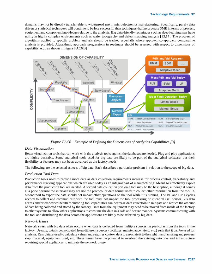
Technology Requirements 37
THE INTERNATIONAL ROADMAP FOR DEVICES AND SYSTEMS: 2017
domains may not be directly transferrable to widespread use in microelectronics manufacturing. Specifically, purely data
driven or statistical techniques will continue to be less successful than techniques that incorporate SME in terms of process,
equipment and component knowledge relative to the analysis. Big data-friendly techniques such as deep learning may have
utility in highly complex environments such as wafer topography and defect mapping analysis [13,14]. The progress of
algorithms applied to specific problem analysis should be tracked especially where approach-to-approach comparative
analysis is provided. Algorithmic approach progressions in roadmaps should be assessed with respect to dimensions of
capability, e.g., as shown in Figure FAC6[3].
Figure FAC6 Example of Defining the Dimensions of Analytics Capabilities [3]
Data Visualization
Better visualization tools that can work with the analysis tools against the databases are needed. Plug and play applications
are highly desirable. Some analytical tools used for big data are likely to be part of the analytical software, but their
flexibility or features may not be as advanced as the factory needs.
The following are the selected aspects of big data. Each describes a particular problem in relation to the scope of big data.
Production Tool Data
Production tools need to provide more data as data collection requirements increase for process control, traceability and
performance tracking applications which are used today as an integral part of manufacturing. Means to effectively export
data from the production tool are needed. A second data collection port on a tool may be the best option, although it comes
at a price because the interface may not use the protocol or data format used to collect other information from the tool. A
second port to export the data should not impact other operations on the tool while it is running. The I/O and CPU cycles
needed to collect and communicate with the tool must not impact the tool processing or intended use. Sensor Bus data
access and/or embedded health monitoring tool capabilities can decrease data collection to mitigate and reduce the amount
of data being collected and stored by the factory. Data from the equipment may need to be moved from inside of the factory
to other systems to allow other applications to consume the data in a safe and secure manner. Systems communicating with
the tool and distributing the data across the applications are likely to be affected by big data.
Network Issues
Network stress with big data often occurs when data is collected from multiple sources, in particular from the tools in the
factory. Usually, data is consolidated from different sources (facilities, maintenance, yield, etc.) such that it can be used for
analysis. Raw data is used to calculate values and requires context data to associate it to the right manufacturing and process
step, material, equipment used, etc. These issues have the potential to overload the existing networks and infrastructure
requiring special appliances to mitigate the network usage.
38 Technology Requirements
THE INTERNATIONAL ROADMAP FOR DEVICES AND SYSTEMS: 2017
Table FAC13 Big Data Technology Requirements
5.9. CONTROL SYSTEMS ARCHITECTURES NEEDS
5.9.1. SCOPE
The scope of Control Systems Architectures (CSA) is control aspects that are common across FI technologies. It does not
include low level control such as Mass Flow Control inside a tool, but rather covers control at the higher levels such as
process run-to-run control and control associated with manufacturing execution systems. This section addresses the
challenges associated with both the evolution and potential revolution of these control systems. Evolutionary items include
more granular control, higher speed control, higher control quality, and higher levels of control capability. Potentially
revolutionary items include the possibility of new control paradigms and new control platforms.
5.9.2. CONTROL SYSTEMS VISION
The overall control systems vision is not concisely defined here because it isn’t clear how new control technologies might
be embraced, and the pace of control system evolution is so rapid that unforeseen technologies might appear over the next
few years. However evolutionary aspects of the vision can be specified, such as granularity, speed, quality and capabilities.
5.9.3. CONTROL SYSTEMS GRANULARITY
Control systems granularity will increase for capabilities such as run-to-run (R2R) control as the concept of a controllable
“run” evolves from a lot to a wafer (i.e., wafer-to-wafer (W2W) control) to within wafer (WIW) control. An example of
WIW control in this context is “shot-to-shot” control in lithography. Achieving this level of granularity will require that
equipment and metrology provide the necessary feed forward and feedback information in an equally granular fashion, but
also in a timely fashion. This is especially true for the feed forward component of control as controllers generally treat this
information as a disturbance rather than a component for model adaptation. Issues of throughput impact and reporting delay
of metrology systems will be addressed in-part by the augmentation of these systems with virtual metrology. These
augmented metrology systems will have to balance speed and quality to meet the requirements of the control systems;
reporting of measurement and predicted measurement quality along with measurement value will be required for
optimization of the consuming control systems.
5.9.4. CONTROL SYSTEMS SPEED AND QUALITY
As noted above, there will be constant pressure on many control systems solutions to provide control advices at higher
speeds (both in terms of response time and frequency) in the face of increasing amounts of data to process (and other big
data issues) and increasingly complex control algorithms. Improvements in computing power will address this requirement
to some extent, however new control approaches will also be explored. One example is time-synchronized control, where
the control network is synchronized using capabilities such as NTP or PTP4, and the control capability utilizes this
synchronization and time stamping of data. Another example is just-in-time style control systems decision making where
the controller is given a time deadline for providing an advice and the controller determines the “best” advice given that
deadline, thereby balancing speed and quality for a particular application.
Another dimension of control system quality improvement will be the speed of control system solution delivery,
qualification and deployment, for both new systems and system updates. As an example, the move to event-based control
(e.g., business rules or control “strategies”) allows for the relatively easy addition of new “control rules” as new capabilities
are deployed. Modularity and “plug-and-play” capability (i.e., rapid and modular software exchange) of control algorithms
will allow for improved comparative analyses and more rapid deployment of control systems improvements.
5.9.5. CONTROL SYSTEMS CAPABILITIES
Control systems capabilities will continue to improve in a number of common ways such as 1), addressing the big data
issues in control, thereby allowing for the use of more and higher quality data in control decisions, 2), development of
improved algorithms for control in general and for control related to a specific control task, and 3), movement to control
software architectures that allow for cost-effective enhancement of control capabilities.
A second dimension in which control capabilities will increase is in the area of mobile computing. This includes mobile
computing units (e.g., tablets) for monitoring and control of systems (e.g., maintenance logging) as well as mechanisms for
remote monitoring and control of systems (e.g., outside of the cleanroom). In both cases issues of security and safety must
4 Networked Time Protocol and Precision Time Protocol: Please see SEMI E148—Specification for Time Synchronization and
Definition of the TS-Clock Object
Potential Solutions 39
THE INTERNATIONAL ROADMAP FOR DEVICES AND SYSTEMS: 2017
be continually addressed. In both cases technologies not specific to microelectronics manufacturing will increasingly be
leveraged.
A third dimension in which control capabilities will increase is through the effective combination, capture, storage and
sharing/access of control system technology combined with process and equipment expertise. Control systems capability
improvement in many areas will increasingly rely on the collective use of control, equipment and process knowledge. For
example, statistical models for R2R control will, in many cases, be replaced by phenomenological model forms that are
stochastically tuned. Methods for capture and reuse of these capabilities and the associated knowledge will be developed.
Development of these methods will require addressing technical, standardization, and intellectual property issues depending
on the scope of re-use.
5.9.6. FUTURE CONTROL PARADIGMS
The future of control in many aspects of FI is unclear and is evolving quickly. Some control paradigms that are being or
will be considered are:
• Cloud-based storage with secure global access methods: The advent of cloud-based technologies will impact
control systems architectures. This will include cloud-based software delivery/update/support mechanisms, hosted
services and more movement towards software as a service (SOS). The cloud will enhance the capability for
cooperation between user, OEM and control systems supplier, however use of these capabilities will require the
addressing of number of security and IP issues.
• Distributed control and autonomous control: The advent of technologies such as web-based services and tablets
has resulted in the enabling of a highly distributed control environment where disparate capabilities and suppliers
can be brought together to achieve control objectives, moving away from the centralized control concept. This
technology trend is already being harnessed in many FI domains (e.g., mobile computing units for maintenance
management or process monitoring), however the level and timing of impact on the FI control approach as a whole
is unclear. It is likely that movement to this control paradigm will be guided by trends across manufacturing in
general rather than trends specific to microelectronics manufacturing.
• Machine learning and artificial intelligence: This paradigm in control systems architectures involves the
enhancement of these systems so that they can “learn” from the environment as reported through the data. Adaptive
model-based control systems (e.g., R2R controllers) may be thought of as learning from the environment; predictive control systems (see ARP section) might also be thought of as learning to some extent as predictive
models are tuned. It is expected that more comprehensive learning techniques will be explored and applied to
control systems architectures; these techniques and their application will likely be a trend observed across
manufacturing in general with microelectronics manufacturing following this general manufacturing trend.
5.9.7. TECHNOLOGY REQUIREMENTS AND POTENTIAL SOLUTIONS
Achievement of the control system architectural vision is associated with a number of technology requirements which have
been presented in the previous section. These requirements will be further quantified in a CSA requirements table in future
versions of this document. A quantified roadmap for potential solutions in the CSA area will also be provided in future
versions of this document.
6. POTENTIAL SOLUTIONS The principal goals of factory integration are maintaining cost per unit area of silicon, decreasing factory ramp time, and,
increasing factory flexibility to changing technology and business needs. The difficult challenges of 1) responding to
complex business requirements; 2) High potential of waste generation and inclusion in factory operations and resources due
to the high operation complexity; 3) managing the high factory complexity; 4) meeting factory and equipment reliability
needs, 5) meeting the fab flexibility, extendibility, and scalability needs; 6) meeting the complex process and its control
requirements for the leading edge device at production volumes; 7) comprehending ever increasing global restrictions on
environmental issues; 8) preparing for the emerging factory paradigm and next wafer size must be addressed to achieve
these goals. Potential solutions are identified for Factory Operations, Production Equipment, Material Handling Systems,
Factory Information and Control Systems, and Facilities. Note that the bars containing wafer diameter data represent
potential solutions that are wafer-size specific.
Potential solutions are shown as “Research required,” “Development underway,” “Qualification/pre-production”, or
“Continuous improvement”, coded in potential solutions tables as shown below. The purpose is to provide guidance to
researchers, suppliers, and IC makers on the timing required to successfully implementing solutions into factories. In some
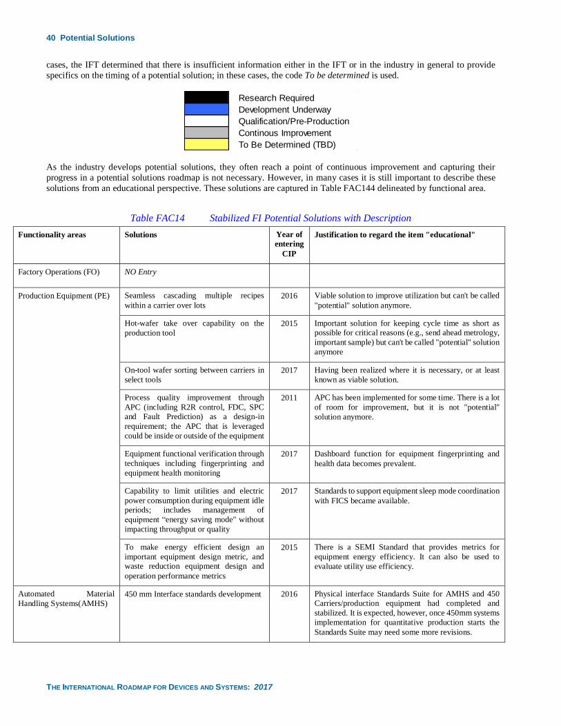
40 Potential Solutions
THE INTERNATIONAL ROADMAP FOR DEVICES AND SYSTEMS: 2017
cases, the IFT determined that there is insufficient information either in the IFT or in the industry in general to provide
specifics on the timing of a potential solution; in these cases, the code To be determined is used.
As the industry develops potential solutions, they often reach a point of continuous improvement and capturing their
progress in a potential solutions roadmap is not necessary. However, in many cases it is still important to describe these
solutions from an educational perspective. These solutions are captured in Table FAC144 delineated by functional area.
Table FAC14 Stabilized FI Potential Solutions with Description
Functionality areas Solutions Year of
entering
CIP
Justification to regard the item "educational"
Factory Operations (FO) NO Entry
Production Equipment (PE) Seamless cascading multiple recipes
within a carrier over lots
2016 Viable solution to improve utilization but can't be called
"potential" solution anymore.
Hot-wafer take over capability on the
production tool
2015 Important solution for keeping cycle time as short as
possible for critical reasons (e.g., send ahead metrology,
important sample) but can't be called "potential" solution
anymore
On-tool wafer sorting between carriers in
select tools
2017 Having been realized where it is necessary, or at least
known as viable solution.
Process quality improvement through
APC (including R2R control, FDC, SPC
and Fault Prediction) as a design-in
requirement; the APC that is leveraged
could be inside or outside of the equipment
2011 APC has been implemented for some time. There is a lot
of room for improvement, but it is not "potential"
solution anymore.
Equipment functional verification through
techniques including fingerprinting and
equipment health monitoring
2017 Dashboard function for equipment fingerprinting and
health data becomes prevalent.
Capability to limit utilities and electric
power consumption during equipment idle
periods; includes management of
equipment “energy saving mode" without
impacting throughput or quality
2017 Standards to support equipment sleep mode coordination
with FICS became available.
To make energy efficient design an
important equipment design metric, and
waste reduction equipment design and
operation performance metrics
2015 There is a SEMI Standard that provides metrics for
equipment energy efficiency. It can also be used to
evaluate utility use efficiency.
Automated Material
Handling Systems(AMHS)
450 mm Interface standards development 2016 Physical interface Standards Suite for AMHS and 450
Carriers/production equipment had completed and
stabilized. It is expected, however, once 450mm systems
implementation for quantitative production starts the
Standards Suite may need some more revisions.
Research Required
Development Underway
Qualification/Pre-Production
Continous Improvement
To Be Determined (TBD)
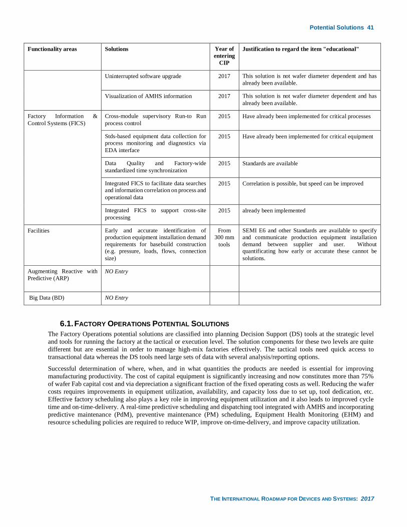
Potential Solutions 41
THE INTERNATIONAL ROADMAP FOR DEVICES AND SYSTEMS: 2017
Functionality areas Solutions Year of
entering
CIP
Justification to regard the item "educational"
Uninterrupted software upgrade 2017 This solution is not wafer diameter dependent and has
already been available.
Visualization of AMHS information 2017 This solution is not wafer diameter dependent and has
already been available.
Factory Information &
Control Systems (FICS)
Cross-module supervisory Run-to Run
process control
2015 Have already been implemented for critical processes
Stds-based equipment data collection for
process monitoring and diagnostics via
EDA interface
2015 Have already been implemented for critical equipment
Data Quality and Factory-wide
standardized time synchronization
2015 Standards are available
Integrated FICS to facilitate data searches
and information correlation on process and
operational data
2015 Correlation is possible, but speed can be improved
Integrated FICS to support cross-site
processing
2015 already been implemented
Facilities Early and accurate identification of
production equipment installation demand
requirements for basebuild construction
(e.g. pressure, loads, flows, connection
size)
From
300 mm
tools
SEMI E6 and other Standards are available to specify
and communicate production equipment installation
demand between supplier and user. Without
quantificating how early or accurate these cannot be
solutions.
Augmenting Reactive with
Predictive (ARP)
NO Entry
Big Data (BD) NO Entry
6.1. FACTORY OPERATIONS POTENTIAL SOLUTIONS
The Factory Operations potential solutions are classified into planning Decision Support (DS) tools at the strategic level
and tools for running the factory at the tactical or execution level. The solution components for these two levels are quite
different but are essential in order to manage high-mix factories effectively. The tactical tools need quick access to
transactional data whereas the DS tools need large sets of data with several analysis/reporting options.
Successful determination of where, when, and in what quantities the products are needed is essential for improving
manufacturing productivity. The cost of capital equipment is significantly increasing and now constitutes more than 75%
of wafer Fab capital cost and via depreciation a significant fraction of the fixed operating costs as well. Reducing the wafer
costs requires improvements in equipment utilization, availability, and capacity loss due to set up, tool dedication, etc.
Effective factory scheduling also plays a key role in improving equipment utilization and it also leads to improved cycle
time and on-time-delivery. A real-time predictive scheduling and dispatching tool integrated with AMHS and incorporating
predictive maintenance (PdM), preventive maintenance (PM) scheduling, Equipment Health Monitoring (EHM) and
resource scheduling policies are required to reduce WIP, improve on-time-delivery, and improve capacity utilization.
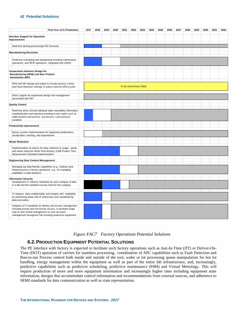
42 Potential Solutions
THE INTERNATIONAL ROADMAP FOR DEVICES AND SYSTEMS: 2017
Figure FAC7 Factory Operations Potential Solutions
6.2. PRODUCTION EQUIPMENT POTENTIAL SOLUTIONS
The PE interface with factory is expected to facilitate such factory operations such as Just-In-Time (JIT) or Deliver-On-
Time (DOT) operation of carriers for seamless processing, coordination of APC capabilities such as Fault Detection and
Run-to-run Process control both inside and outside of the tool, wafer or lot processing queue manipulation for hot lot
handling, energy management within the equipment as well as part of the entire fab infrastructure, and, increasingly,
predictive capabilities such as predictive scheduling, predictive maintenance (PdM) and Virtual Metrology. This will
require production of more and more equipment information and increasingly higher rates including equipment state
information, designs that accommodate control information and recommendations from external sources, and adherence to
SEMI standards for data communication as well as state representation.
First Year of IC Production 2017 2018 2019 2020 2021 2022 2023 2024 2025 2026 2027 2028 2029 2030 2031 2032
Real-time (during processing) FDC functions
Manufacturing Execution
Predictive scheduling and dispatching including maintenance
operations, and NPW operations, integrated with AMHS
DFM and NPI design and output to include process control
and Fault Detection settings to reduce need for DFM cycles To Be Determined (TBD)
Direct support for experiment design and management
associated with NPI
Quality Control
Real-time (time critical) Individual wafer traceability information
standardization and reporting including in-tool states such as
wafer position and process pre-process / post-process
condition
Productivity Improvement
factory system implementation for equipment performance
visualization, tracking, and improvement
Waste Reduction
Implementation of metrics for data collection & usage, waste
and waste reduction (Wait-Time-Waste); E168 Product Time
Measurement Standard Implementation
Engineering Data Content Management
Managing big data-friendly capabilities (e.g., Hadoop style
infrastructures) in factory operations, e.g., for managing
availability to data analytics
Information Security
Development of industry standards for each category of data
in a fab and the standard security level for that category
To balance data confidentiality and integrity with availability
by partitioning datas with IP protections and standardizing
data encryption.
Adoption of IT standards for identity and access management
including human and non-human access, to facilitate single
sign-on and central management on user accounts
management throughout Fab including production equipment
Cooperation between Design for
Manufacturing (DFM) and New Product
Introduction (NPI)
Decision Support for Operation
Improvement

Potential Solutions 43
THE INTERNATIONAL ROADMAP FOR DEVICES AND SYSTEMS: 2017
For the same type of recipes in which the same process resources are used almost for the same process settings the PE
should behave as it is processing wafers under the same process recipe so to keep the seamless processing. This requirement
implies that the PE needs to be capable of understanding the contents of the recipes, or, that the factory system sends a flag
to PE to make PE accept any recipe without any NPW operations. More discussion is required to understand the requirement
of such control and implementation methodology.
It is noteworthy that many operation controls become heavily dependent on scheduling in order to reduce WIP, to facilitate
reasonable scheduled maintenance of PE, and, to gain flexibility against unexpected events in the fab. Predictive scheduling
will become an integral part of equipment operation to optimize scheduling and reduce wait-time waste. It is also noteworthy
to highlight that process controls need to become more model-based for higher reusability and to reduce the engineering
burden and time consumption. Equipment should be designed with APC in mind. In some cases, this will mean that APC
will be an integral part of the delivered tool solution, while in other cases it will mean that the equipment is produced to be
“APC ready”, provide the necessary timely data and allowing the appropriate control to support APC. Research can be
better focused toward the innovations required to achieve these objectives.
The movement to 450 mm as well as movement to new process materials will present challenges. The movement to 450 mm
should not result in a reduction of any operations or product quality metrics.
Just as with the fab in general, equipment operations will gradually evolve from reactive to reactive augmented with
predictive operations. This is discussed in detail in the ARP section. Corrective maintenance will be augmented with
predictive maintenance. Fault detection and scrap reduction shall be augmented with fault prediction and scrap avoidance.
Reactive scheduling shall be augmented with predictive scheduling. Metrology will be supplemented with virtual
metrology. This change in mindset shall have an impact on equipment design and operations.
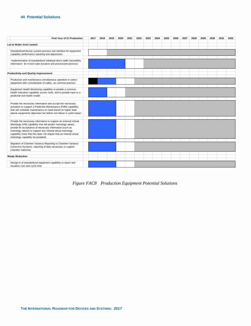
44 Potential Solutions
THE INTERNATIONAL ROADMAP FOR DEVICES AND SYSTEMS: 2017
Figure FAC8 Production Equipment Potential Solutions
First Year of IC Production 2017 2018 2019 2020 2021 2022 2023 2024 2025 2026 2027 2028 2029 2030 2031 2032
Lot to Wafer level control
Standardized factory system-process tool interface for equipment
capability performance reporting and adjustment
Implementation of standardized individual direct wafer traceability
information for in-tool state (location and process/pre-process)
Productivity and Quality Improvement
Production and maintenance simultaneous operation in select
equipment with consideration of safety, as common practice
Equipment Health Monitoring capability to provide a common
health indication capability across tools, and to provide input to a
predictive tool health model
Provide the necessary information and accept the necessary
actuation to support a Predictive Maintenance (PdM) capability
that will schedule maintenance on need based on higher level
(above equipment) objectives but before tool failure or yield impact
Provide the necessary information to support an external Virtual
Metrology (VM) capability that will predict metrology values;
provide for acceptance of necessary information (such as
metrology values) to support any internal virtual metrology
capability (note that this does not require that an internal virtual
metrology capability be provided).
Migration of Chamber Variance Reporting to Chamber Variance
Correction Systems; reporting of data necessary to support
chamber matching
Waste Reduction
Design-in of standardized equipment capability to report and
visualize cost and cycle time
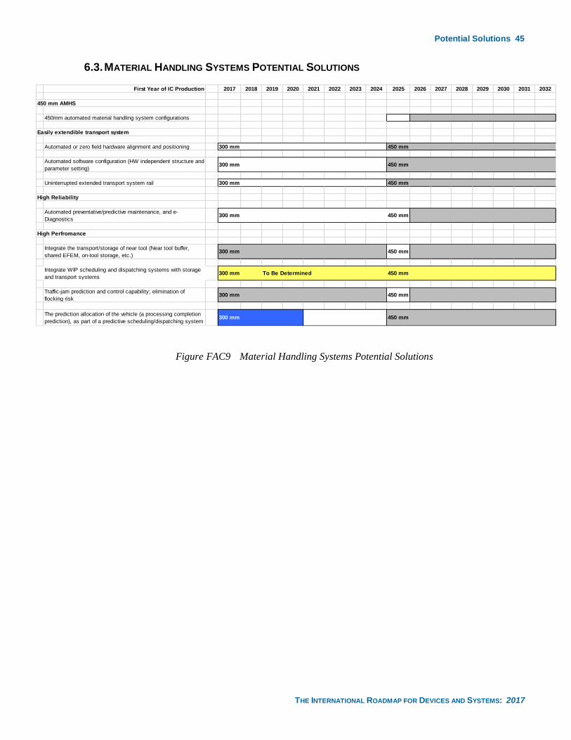
Potential Solutions 45
THE INTERNATIONAL ROADMAP FOR DEVICES AND SYSTEMS: 2017
6.3. MATERIAL HANDLING SYSTEMS POTENTIAL SOLUTIONS
Figure FAC9 Material Handling Systems Potential Solutions
First Year of IC Production 2017 2018 2019 2020 2021 2022 2023 2024 2025 2026 2027 2028 2029 2030 2031 2032
450 mm AMHS
450mm automated material handling system configurations
Automated or zero field hardware alignment and positioning 300 mm 450 mm
Automated software configuration (HW independent structure and
parameter setting)300 mm 450 mm
Uninterrupted extended transport system rail 300 mm 450 mm
Automated preventative/predictive maintenance, and e-
Diagnostics300 mm 450 mm
Integrate the transport/storage of near tool (Near tool buffer,
shared EFEM, on-tool storage, etc.)300 mm 450 mm
Integrate WIP scheduling and dispatching systems with storage
and transport systems300 mm To Be Determined 450 mm
Traffic-jam prediction and control capability; elimination of
flocking risk300 mm 450 mm
The prediction allocation of the vehicle (a processing completion
prediction), as part of a predictive scheduling/dispatching system300 mm 450 mm
High Perfromance
High Reliability
Easily extendible transport system
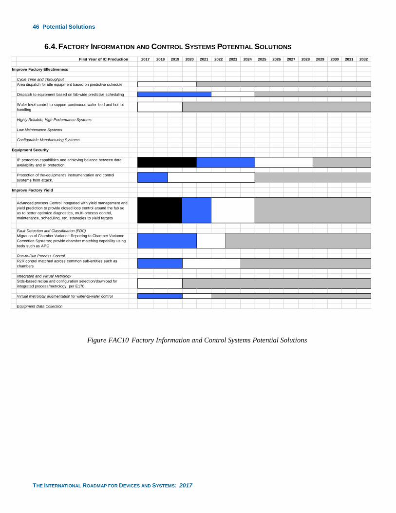
46 Potential Solutions
THE INTERNATIONAL ROADMAP FOR DEVICES AND SYSTEMS: 2017
6.4. FACTORY INFORMATION AND CONTROL SYSTEMS POTENTIAL SOLUTIONS
Figure FAC10 Factory Information and Control Systems Potential Solutions
First Year of IC Production 2017 2018 2019 2020 2021 2022 2023 2024 2025 2026 2027 2028 2029 2030 2031 2032
Improve Factory Effectiveness
Cycle Time and Throughput
Area dispatch for idle equipment based on predictive schedule
Dispatch to equipment based on fab-wide predictive scheduling
Wafer-level control to support continuous wafer feed and hot-lot
handling
Highly Reliable, High Performance Systems
Low Maintenance Systems
Configurable Manufacturing Systems
IP protection capabilities and achieving balance between data
availability and IP protection
Protection of the equipment's instrumentation and control
systems from attack.
Advanced process Control integrated with yield management and
yield prediction to provide closed loop control around the fab so
as to better optimize diagnostics, multi-process control,
maintenance, scheduling, etc. strategies to yield targets
Fault Detection and Classification (FDC)
Migration of Chamber Variance Reporting to Chamber Variance
Correction Systems; provide chamber matching capability using
tools such as APC
Run-to-Run Process Control
R2R control matched across common sub-entities such as
chambers
Integrated and Virtual Metrology
Stds-based recipe and configuration selection/download for
integrated process/metrology, per E170
Virtual metrology augmentation for wafer-to-wafer control
Equipment Data Collection
Equipment Security
Improve Factory Yield
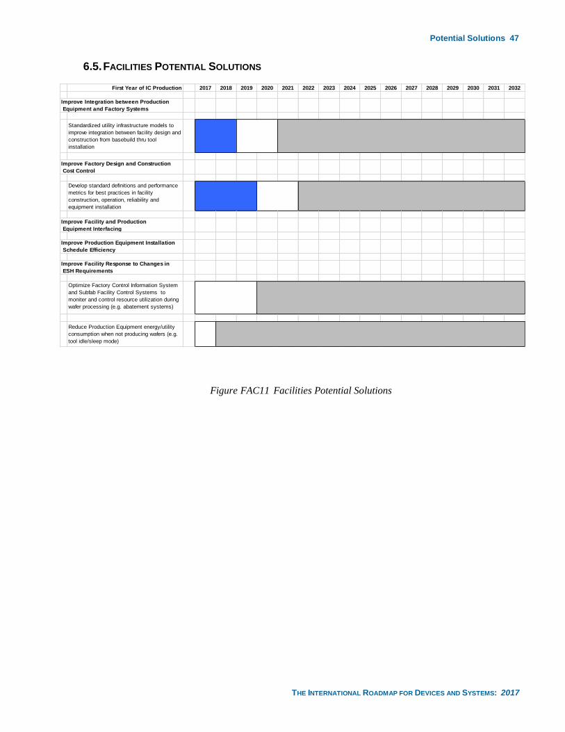
Potential Solutions 47
THE INTERNATIONAL ROADMAP FOR DEVICES AND SYSTEMS: 2017
6.5. FACILITIES POTENTIAL SOLUTIONS
Figure FAC11 Facilities Potential Solutions
First Year of IC Production 2017 2018 2019 2020 2021 2022 2023 2024 2025 2026 2027 2028 2029 2030 2031 2032
Standardized utility infrastructure models to
improve integration between facility design and
construction from basebuild thru tool
installation
Develop standard definitions and performance
metrics for best practices in facility
construction, operation, reliability and
equipment installation
Optimize Factory Control Information System
and Subfab Facility Control Systems to
moniter and control resource utilization during
wafer processing (e.g. abatement systems)
Reduce Production Equipment energy/utility
consumption when not producing wafers (e.g.
tool idle/sleep mode)
Improve Integration between Production
Equipment and Factory Systems
Improve Factory Design and Construction
Cost Control
Improve Facility and Production
Equipment Interfacing
Improve Production Equipment Installation
Schedule Efficiency
Improve Facility Response to Changes in
ESH Requirements
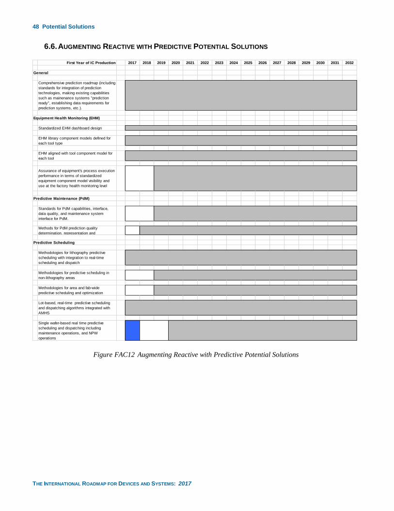
48 Potential Solutions
THE INTERNATIONAL ROADMAP FOR DEVICES AND SYSTEMS: 2017
6.6. AUGMENTING REACTIVE WITH PREDICTIVE POTENTIAL SOLUTIONS
Figure FAC12 Augmenting Reactive with Predictive Potential Solutions
First Year of IC Production 2017 2018 2019 2020 2021 2022 2023 2024 2025 2026 2027 2028 2029 2030 2031 2032
General
Comprehensive prediction roadmap (including
standards for integration of prediction
technologies, making existing capabilities
such as mainenance systems "prediction
ready", establishing data requirements for
prediction systems, etc.).
Equipment Health Monitoring (EHM)
Standardized EHM dashboard design
EHM library component models defined for
each tool type
EHM aligned with tool component model for
each tool
Assurance of equipment's process execution
performance in terms of standardized
equipment component model visibility and
use at the factory health monitoring level
Predictive Maintenance (PdM)
Standards for PdM capabilities, interface,
data quality, and maintenance system
interface for PdM.
Methods for PdM prediction quality
determination, representation and
Predictive Scheduling
Methodologies for lithography predictive
scheduling with integration to real-time
scheduling and dispatch
Methodologies for predictive scheduling in
non-lithography areas
Methodologies for area and fab-wide
predictive scheduling and optimization
Lot-based, real-time predictive scheduling
and dispatching algorithms integrated with
AMHS
Single wafer-based real time predictive
scheduling and dispatching including
maintenance operations, and NPW
operations
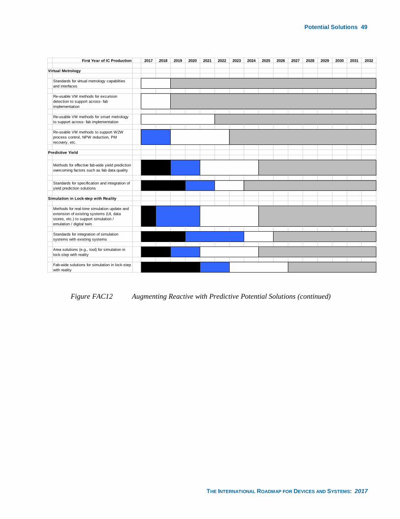
Potential Solutions 49
THE INTERNATIONAL ROADMAP FOR DEVICES AND SYSTEMS: 2017
Figure FAC12 Augmenting Reactive with Predictive Potential Solutions (continued)
First Year of IC Production 2017 2018 2019 2020 2021 2022 2023 2024 2025 2026 2027 2028 2029 2030 2031 2032
Virtual Metrology
Standards for virtual metrology capabilties
and interfaces
Re-usable VM methods for excursion
detection to support across- fab
implementation
Re-usable VM methods for smart metrology
to support across- fab implementation
Re-usable VM methods to support W2W
process control, NPW reduction, PM
recovery, etc.
Predictive Yield
Methods for effective fab-wide yield prediction
overcoming factors such as fab data quality
Standards for specification and integration of
yield prediction solutions
Simulation in Lock-step with Reality
Methods for real-time simulation update and
extension of existing systems (UI, data
stores, etc.) to support simulation /
emulation / digital twin.
Standards for integration of simulation
systems with existing systems
Area solutions (e.g., tool) for simulation in
lock-step with reality
Fab-wide solutions for simulation in lock-step
with reality
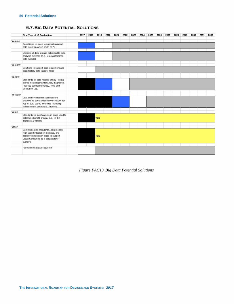
50 Potential Solutions
THE INTERNATIONAL ROADMAP FOR DEVICES AND SYSTEMS: 2017
6.7. BIG DATA POTENTIAL SOLUTIONS
Figure FAC13 Big Data Potential Solutions
First Year of IC Production 2017 2018 2019 2020 2021 2022 2023 2024 2025 2026 2027 2028 2029 2030 2031 2032
Capabilities in place to support required
data retention which could be ALL
Methods of data storage optimized to data
analysis methods (e.g., via standardized
data models)
Solutions to support peak equipment and
peak factory data transfer rates
Standards for data models of key FI data
stores including maintenance, diagnostic,
Process control/metrology, yield and
Execution Log.
Data quality baseline specifications
provided as standardized metric values for
key FI data stores including including
maintenance, diagnostic, Process
Standardized mechanisms in place used to
determine benefit of data, e.g., in $ /
TeraByte of storage
TBD
Communication standards, data models,
high-speed integration methods, and
security protocols in place to support
Cloud Computing as a solution for FI
systems
TBD
Fab-wide big data ecosystem
Other
Volume
Velocity
Variety
Veracity
Value
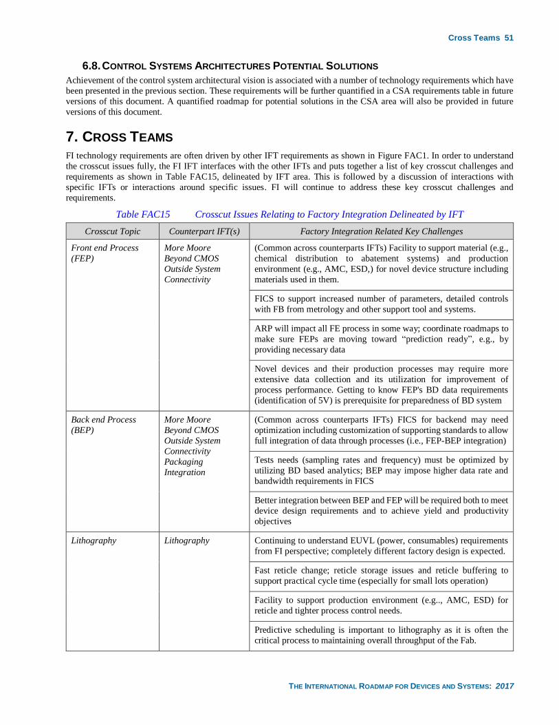
Cross Teams 51
THE INTERNATIONAL ROADMAP FOR DEVICES AND SYSTEMS: 2017
6.8. CONTROL SYSTEMS ARCHITECTURES POTENTIAL SOLUTIONS
Achievement of the control system architectural vision is associated with a number of technology requirements which have
been presented in the previous section. These requirements will be further quantified in a CSA requirements table in future
versions of this document. A quantified roadmap for potential solutions in the CSA area will also be provided in future
versions of this document.
7. CROSS TEAMS FI technology requirements are often driven by other IFT requirements as shown in Figure FAC1. In order to understand
the crosscut issues fully, the FI IFT interfaces with the other IFTs and puts together a list of key crosscut challenges and
requirements as shown in Table FAC15, delineated by IFT area. This is followed by a discussion of interactions with
specific IFTs or interactions around specific issues. FI will continue to address these key crosscut challenges and
requirements.
Table FAC15 Crosscut Issues Relating to Factory Integration Delineated by IFT
Crosscut Topic Counterpart IFT(s) Factory Integration Related Key Challenges
Front end Process
(FEP)
More Moore
Beyond CMOS
Outside System
Connectivity
(Common across counterparts IFTs) Facility to support material (e.g.,
chemical distribution to abatement systems) and production
environment (e.g., AMC, ESD,) for novel device structure including
materials used in them.
FICS to support increased number of parameters, detailed controls
with FB from metrology and other support tool and systems.
ARP will impact all FE process in some way; coordinate roadmaps to
make sure FEPs are moving toward “prediction ready”, e.g., by
providing necessary data
Novel devices and their production processes may require more
extensive data collection and its utilization for improvement of
process performance. Getting to know FEP's BD data requirements
(identification of 5V) is prerequisite for preparedness of BD system
Back end Process
(BEP)
More Moore
Beyond CMOS
Outside System
Connectivity
Packaging
Integration
(Common across counterparts IFTs) FICS for backend may need
optimization including customization of supporting standards to allow
full integration of data through processes (i.e., FEP-BEP integration)
Tests needs (sampling rates and frequency) must be optimized by
utilizing BD based analytics; BEP may impose higher data rate and
bandwidth requirements in FICS
Better integration between BEP and FEP will be required both to meet
device design requirements and to achieve yield and productivity
objectives
Lithography Lithography Continuing to understand EUVL (power, consumables) requirements
from FI perspective; completely different factory design is expected.
Fast reticle change; reticle storage issues and reticle buffering to
support practical cycle time (especially for small lots operation)
Facility to support production environment (e.g.., AMC, ESD) for
reticle and tighter process control needs.
Predictive scheduling is important to lithography as it is often the
critical process to maintaining overall throughput of the Fab.
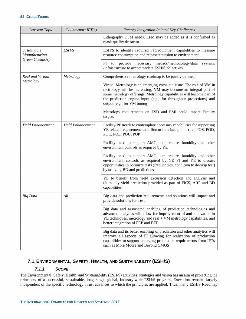
52 Cross Teams
THE INTERNATIONAL ROADMAP FOR DEVICES AND SYSTEMS: 2017
Crosscut Topic Counterpart IFT(s) Factory Integration Related Key Challenges
Lithography DFM needs. EFM may be added as it is confirmed as
mask quality detractor.
Sustainable
Manufacturing
Green Chemistry
ESH/S ESH/S to identify required Fab/equipment capabilities to measure
resource consumption and release/emission to environment.
FI to provide necessary metrics/methodology/data systems
/infrastructure to accommodate ESH/S objectives
Real and Virtual
Metrology
Metrology Comprehensive metrology roadmap to be jointly defined.
Virtual Metrology is an emerging cross-cut issue. The role of VM in
metrology will be increasing; VM may become an integral part of
some metrology offerings. Metrology capabilities will become part of
the prediction engine input (e.g., for throughput projections) and
output (e.g., for VM tuning).
Metrology requirements on ESD and EMI could impact Facility
targets
Yield Enhancement Yield Enhancement Facility/PE needs to contemplate necessary capabilities for supporting
YE related requirements at different interface points (i.e., POS, POD,
POC, POE, POU, POP)
Facility need to support AMC, temperature, humidity and other
environment controls as required by YE
Facility need to support AMC, temperature, humidity and other
environment controls as required by YE FI and YE to discuss
opportunities to optimize tests (frequencies, condition to do/skip test)
by utilizing BD and predictions
YE to benefit from yield excursion detection and analysis and
ultimately yield prediction provided as part of FICS, ARP and BD
capabilities.
Big Data All Big data and prediction requirements and solutions will impact and
provide solutions for Test.
Big data and associated enabling of prediction technologies and
advanced analytics will allow for improvement of and innovation in
YE techniques, metrology and real + VM metrology capabilities, and
better integration of FEP and BEP.
Big data and its better enabling of prediction and other analytics will
improve all aspects of FI allowing for realization of production
capabilities to support emerging production requirements from IFTs
such as More Moore and Beyond CMOS
7.1. ENVIRONMENTAL, SAFETY, HEALTH, AND SUSTAINABILITY (ESH/S)
7.1.1. SCOPE
The Environmental, Safety, Health, and Sustainability (ESH/S) activities, strategies and vision has an aim of projecting the
principles of a successful, sustainable, long range, global, industry-wide ESH/S program. Execution remains largely
independent of the specific technology thrust advances to which the principles are applied. Thus, many ESH/S Roadmap
Cross Teams 53
THE INTERNATIONAL ROADMAP FOR DEVICES AND SYSTEMS: 2017
elements, such as the Difficult Challenges and the Technology Requirements, feed directly into the other IFTs in the IRDS,
notably Factory Integration. The six basic and overarching ESH/S Roadmap strategies are:
• To fully understand (characterize) processes and materials during the development phase;
• To use materials that are less hazardous or whose byproducts are less hazardous;
• To design products and systems (equipment and facilities) that consume less raw materials and resources;
• To make the factory, and fundamental industry supply chain safe for employees and the environment;
• To provide clear global ESH/S perspective in regard to new materials, sustainability and green chemistry;
• To provide proactive engagement with stakeholder partners and customers and reset strategic focus on the roadmap
goals.
By applying these six core strategies as the essential elements to success, the Microelectronics Industry continues to be an
ESH/S leader as well as an overall technology leader. Microelectronics manufacturers have adopted a business approach to
ESH/S which uses principles that are deeply integrated with factory manufacturing technologies, supply chain, products,
and services. Product Lifecycle and Green Chemistry outlines are added for 2015.
ESH/S and Factory Integration Synergy
In aligning with the industry trend towards tighter integration of ESH/S and FI activities, the ESH/S IFT contributes this
section in the FI chapter. The reader is encouraged to refer back to the full ESH/S chapter when reading this section to
understand the full ESH/S roadmap.
The increased synergy between ESH/S and FI efforts can be summarized with the following ESH/S strategies:
• The roadmap process will continue to quantify factory environmental factors
• Roadmap will include, new materials, sustainability and green chemistry
• Provide proactive engagement with stakeholder partners and reset strategic focus on the roadmap goals.
• Continue focus on factory, and supply chain safety for employees and the environment
7.2. YIELD ENHANCEMENT
7.2.1. SCOPE
Development of good yield management strategies reduces costs and investment risks. A factory yield model defines typical
operational performance and permits a Pareto of performance and yield detractors. A factory model based on experimental
mapping of process parameters and process control strategies reduces the need for increased metrology tools and monitor
wafers. It is also critical to determine tolerance variations for process parameters and interactions between processes to
reduce reliance on end-of-line inspections. Factory models should also be capable of handling defect reduction inputs to
assure efficient factory designs for rapid construction, rapid yield ramp, high equipment utilization, and extendibility to
future technology generations. Temperature and humidity metrics alone with AMC requirements will be jointly worked out
by Factory Integration and Yield IFTs.
Over the longer term yield prediction will be utilized along with feedback to factory systems such as scheduling/dispatch,
maintenance management and process control to provide for better control to yield and throughput objectives. Realization
of these yield prediction with feedback systems will require tighter coordination between yield and factory operation data
management systems.
Yield management systems (YMS) must be developed that can access and correlate information from multiple data sources.
YMS should also work with measurement/metrology equipment from multiple suppliers using pre-competitive standards-
based data models and structures. Longer term Augmenting Reactive with Predictive technologies will result in a capability
for yield prediction; the challenges and potential solutions for this capability will be coordinated with the Yield Management
group. Refer to the Yield Enhancement chapter for a more comprehensive discussion on YMS.
YE and Factory Integration Synergy
In aligning with the industry trend towards tighter integration of YE and FI activities, the YE IFT contributes this section
in the FI chapter. The reader is encouraged to refer back to the full YE chapter when reading this section to understand the
full YE roadmap.
The increased synergy between YE and FI efforts can be summarized with the following ESH/S strategies:
54 Cross Teams
THE INTERNATIONAL ROADMAP FOR DEVICES AND SYSTEMS: 2017
• The road mapping focus will move from a technology orientation to a product/application orientation.
• Airborne molecular contamination (AMC), packaging, liquid chemicals and ultra-pure water were identified as
main focus topics for the next period.
• Electrical characterization methods, big data and modeling will become more and more important for yield
learning and yield prediction.
7.2.2. AIRBORNE MOLECULAR CONTAMINATION
The presence of Airborne Molecular Contamination (AMC) within the processing areas has played a more significant role
as device geometries for integrated circuits shrink. Yield problems caused by AMC are well documented and occur at a
host of different process steps.
Airborne molecular contamination (AMC) control may be implemented either fab-wide or locally at certain critical
processes, potentially also at different levels for different processes. All cleanroom components, such as filters, partition,
electric wire, etc., should be designed and selected considering their outgassing properties. Also, cross-contamination within
the wafer carriers (FOUPs) should be considerable. Visualization, modeling and simulation tools are required to determine
and validate the most appropriate integrated AMC control solutions. Furthermore, these tools should deliver a fair basis to
estimate the cost effectiveness of the proposed solutions.
The “Wafer Environment Contamination Control” tables of the Yield Enhancement Chapter provide recommended
contamination control levels which should be maintained at the interface between cleanroom environment and the part of
the manufacturing equipment (mini-environments) as follows:
• AMC as measured/monitored in the cleanroom air and /or purge gas environment
• Surface Molecular Contamination (SMC) on monitoring wafers
These values reflect the need to reduce AMC from the ambient environment as well as to keep the out-gassing emissions
in the clean room environment at low level.
It is noteworthy that there is a second contamination path regarding AMC that needs to be managed. Wafers leaving process
covered with residues are out-gassing and over time any minienvironment in which processed wafers are temporally staying
or kept for certain duration such as the wafer carrier (FOUP) will be contaminated. These adsorbed contaminations on the
FOUP wall have been observed to re-contaminate cleaned wafers and subsequently contaminate equipment including
expensive metrology equipment. This cross-contamination mechanism has been primarily identified for volatile acids after
dry etching processes but cannot be neglected for other equipment and for other contaminants, such as caustics, organics
and dopants. This cross contamination depends thereby by many factors. There is a need to monitor the FOUP
contamination level as well as the interface between equipment and wafer carriers.
FOUP purging has been proven extremely difficult due to the dead-end type internal design of air spaces between the wafers
as well as the limited possible flow rate. New methods such as vacuum/N2 purge cycles can support faster cleaning times
and overcoming the long dead legs. Nevertheless, further development is needed to establish suitable control limits of FOUP
status and purging efficiency with on-line and off-line methods. Refer to Yield Enhancement Chapter for more information.
Meeting AMC requirements is also addressed from a facilities perspective in the Facilities section of this chapter.
7.2.3. ULTRA-PURE WATER
Ultrapure water (UPW) is purified water with most of the quality parameters below or near their detection limits of the most
advanced metrology. Specific definitions of the water quality requirements to enable future technology are presented.
Particle levels are reduced using the best available ultra-filtration (UF) technology, but today’s particle counting technology
is not able to keep up with critical particle node due to continued scaling of critical microelectronics devices.
The focus will turn to critical parameters such as particles, metals, and organic compounds and the corresponding
characterization methods. Particles remain a high and growing risk, critical for implementing future microelectronics
technology; due to its high sensitivity to reducing line widths. On-line metrology for particles in liquid does not address
killer particle size (sensitivity problem), and therefore, filtration efficiency for killer particles provides limited information.
At the same time, it is apparent that the killer size of the particles has approached filtration capability of the most advanced
final filters. Statistical process control is increasingly being used to monitor the consistency of process parameters. Process
variation of fluid purity can be as critical to wafer yield as the absolute purity of the fluids. Therefore, it is important that
measurement methods detect sufficient number of events to ensure confidence in measured particle concentrations.
Cross Teams 55
THE INTERNATIONAL ROADMAP FOR DEVICES AND SYSTEMS: 2017
Development of other statistically significant particle counting methods or a higher sample volume particle counter is
needed to improve confidence in reported particle counts. Refer to Yield Enhancement Chapter for more information.
7.2.4. ELECTRICAL CHARACTERIZATION METHODS AND VIRTUAL METROLOGY FOR YIELD
CONTROL
In order to overcome the problems of missing sensitivity and high effort consuming metrology for yield control one focus
of the YE group will be the partial replacement of physical based metrology with electrical diagnosis and virtual metrology
wherever feasible. The use of all available data sources and approaches for data analysis will be further elaborated for yield
monitoring. Hereby, a better balance of defect/contamination detection and fault diagnostics/control of electrical
characteristics should be established by including statistical and systematic approaches into YE activities.
Furthermore, virtual metrology becomes more and more essential for yield considerations. Virtual metrology is the defined
as the prediction of post process metrology variables (either measurable or non-measurable) using process and wafer state
information that could include upstream metrology and/or sensor data.
Refer to Yield Enhancement Chapter and the Augmenting Reactive with Predictive (ARP) section of this chapter for more
information.
7.2.5. THE MOVE TOWARDS YIELD PREDICTION
As noted in the ARP section of this chapter, part of the prediction vision is a state of fab operations where “yield and
throughput prediction are an integral part of factory operation optimization”. Yield prediction will also become an integral
part of yield control and enhancement. Big data capabilities will be leveraged to develop and maintain yield prediction
models. These models will provide indications of potential yield excursions as part of the process flow, so as to provide
“real-time”5 indications of issues to avoid quality issues associated with the delay between processing associated with the
yield excursion and the end-of-line e-test and yield analysis (a delay that can often be days or even weeks). Analytics will
identify culprits of yield excursions in terms of process and process parameters; analytics from other prediction
technologies, notably virtual metrology, will be leveraged. Eventually control actions will be defined to allow the evolution
from real-time yield excursion detection to real-time yield excursion control, and then real-time yield continuous
optimization.
7.3. METROLOGY
Metrology systems must be fully integrated into the factory information and control systems to facilitate run-to-run process
control, yield analysis, material tracking through manufacturing, and other off-line analysis. The scope of measurement
data sources will extend from key suppliers (masks and silicon wafers) through Fab, probe, assembly, final test and be
linked to business enterprise level information. Data volumes and data rates will continue to increase dramatically due to
wafer size increases, process technology shrinks, and the big data problem. Virtual metrology (VM) will become an
important solution to augment existing metrology for improving quality without negatively impacting cost in terms of
capital and lost throughput. Refer to the ARP section of this chapter for the VM roadmap. In factories, review and
classification tools may eventually appear in clusters or integrated clusters to create a more efficient factory interface. Some
process equipment will include integrated measurement (IM) capabilities to reduce cycle time and wafer-to-wafer process
variance. The FI and Metrology IFTs will continue to work on the VM and IM requirements. Refer to the Metrology chapter
for overall metrology topics.
7.4. LITHOGRAPHY
The Lithography chapter deals with the difficulties inherent in extending optical methods of patterning to physical limits,
and also evaluates the need to develop entirely new, post-optical lithographic technologies capable of being implemented
into manufacturing. Key challenges that need to be addressed by the Factory Integration team are to ensure the infrastructure
(power and water) readiness for EUVL to improve Advanced Process Control (APC) for lithography equipment (e.g., tighter
control is needed for overlay and edge roughness), and to improve predictive scheduling/dispatch potential solutions for
lithography as it is usually the bottleneck process. Other issues to be addressed include Design for Manufacturing (DFM)
and temperature variation inside the tools, and, AMC and ESD impact on reticle. Refer to Lithography chapter for a more
information.
5 “Real-time” as used here is a response time of sufficient promptness so that process flow is not impacted, and yield is not impacted as
a result of analysis delays. For example, the yield prediction should occur before the next wafer or lot is processed (i.e., seconds or
minutes).
56 Emerging Concepts and Technologies
THE INTERNATIONAL ROADMAP FOR DEVICES AND SYSTEMS: 2017
7.5. MULTI-IFT ISSUE: WAFER DEFECT METROLOGY
Defect metrology continues to be important towards smaller nodes, especially considering new yield challenges like
multiple patterning. The main way to detect yield impacting defects in the production is defect inspection. Therefore, the
most important requirements for inspection and review are now incorporated in the More Moore chapter.
For Heterogenous Integration not small dimensions but 3D integration is the challenge. To find the right solutions for those
inspection requirements and challenges will be the focus.
7.6. MULTI-IFT ISSUE: YIELD MANAGEMENT FOR PACKAGING AND ASSEMBLY
As technology requirements in the assembly and packaging area increase, yield loss and therefore yield improvement
methodologies become essential. In this situation a clear benefit can be drawn from the experience in the FE. Yet the most
appropriate methodologies have to be selected and FE yield tools need to be adapted to BE requirements. The task will be
to define a dedicated roadmap.
Due to the changed focus of Yield Enhancement several cross IFT activities are envisaged, connections with More Moore
(MM), Heterogeneous Integration (HI) and Heterogeneous Components (HC) are necessary.
8. EMERGING CONCEPTS AND TECHNOLOGIES In addition to working on the factory integration sub-sections and cross-IFT challenges, the FI IFT also evaluated key
emerging concepts and technologies that will impact the FI roadmap and cut across all FI areas. This section provides details
on these concepts and technologies which may represent opportunities, but also risks. Some of these concepts and
technologies may deserve increased consideration in future versions of the roadmap, perhaps in the form of their own needs
and potential solutions roadmap subsections.
8.1. SMART MANUFACTURING AND INDUSTRY 4.0
As noted earlier Smart manufacturing (SM) is a term “generally applied to a movement in manufacturing practices towards
integration up and down the supply chain, integration of physical and cyber capabilities, and taking advantage of advanced information for increased flexibility and adaptability” [3–5]. It is often equated with “Industry 4.0” (I4.0), a term that
originated from a project in the German government that promotes a 4th generation of manufacturing that uses concepts
such as cyber-physical systems, virtual copies of real equipment and processes, and decentralized decision making to create
a smart factory [6,7].
8.1.1. THE SMART MANUFACTURING AND INDUSTRY 4.0 VISION
A number of SM and I4.0 common themes are expected to impact the FI roadmap. Some of these already addressed in the
existing FI roadmap include:
• Leveraging big data infrastructures (see section 5.8)
• Integrating the supply chain network (see section 5.2.13 and 8.3)
• Leveraging advanced analytics (see section 5.8.4)
Other aspects of SM and I4.0 that will be addressed in greater detail in future FI roadmap reports include [15]
Improving use of cyber-physical systems (CPS):
CPS refers to the “tight conjoining of and coordination between computational and physical resources” [16]. This is not a
new concept as systems that integrate computational and physical resources have been in existence for some time. However
future SM systems will continue to improve from a CPS perspective in terms of “adaptability, autonomy, efficiency,
functionality, reliability, safety, and usability.”
Improving the use of real-time simulation through realizing the “digital twin”:
“A digital twin refers to a digital replica of physical assets, processes and systems that can be used for various purposes”
[11]. This concept is further refined in this report in section 5.7.2 as “a state of fab operations where … real-time simulation
of all fab operations occurs as an extension of existing system with dynamic updating of simulation models”. Many of the
predictive applications being developed in the industry today will likely continue to evolve to more directly support this
vision.
Emerging Concepts and Technologies 57
THE INTERNATIONAL ROADMAP FOR DEVICES AND SYSTEMS: 2017
Business Paradigm Change: Migration to Cooperative Services-based Approach to FI
The rapid increase in FI requirements (e.g., big data) and capabilities (e.g., prediction) in recent years has led to a change
in the approach to implementing and maintaining FI capabilities. Development and maintenance of emerging capabilities
such as PdM, VM, waste management, and utilities management incorporation into fab objectives, requires intimate
knowledge of the fab objectives, process, equipment and the capabilities themselves. Thus, it has become clear that cost-
effective development and maintenance of these capabilities will require increased and continuous cooperation of users,
OEMs and 3rd party FI capability suppliers. As an example, in a PdM deployment and maintenance effort, the user provides
knowledge of objectives, costs, and metrics of success, along with process and equipment domain expertise. The OEM
provides intimate knowledge of the equipment and PdM best practices for the equipment and serves as a conduit for longer
term enhancement of equipment capabilities based on PdM results. The 3rd party PdM solution provider provides the PdM
solutions which includes a fab-wide integration infrastructure and addresses issues such as security and big data in a
standardized supportable way. During PdM solution maintenance the user leverages the PdM solution and may determine
when enhancements are needed. The OEM continues to provide equipment knowledge and perhaps hardware and software
updates to 1) address new PdM downtime event types as they occur or are addressed, and 2) perhaps reduce the cost of
downtime event types currently addressed by the PdM system. The 3rd party PdM solution provider develops and maintains
the state-of-the-art PdM capability, e.g., implementing improved algorithms and leveraging solution libraries to guide cost-
effective enhancement the PdM capability. This new paradigm of increased cooperation between user, OEM and 3rd party
FI capability supplier will place stronger requirements on issues such as security, IP protection and all big data issues. These
issues will have to be addressed in the FI roadmap.
8.2. SECURITY
The three primary goals of security are to maintain confidentiality (the restriction of access to data and services to specific
machines/human users) and integrity (accuracy/completeness of data and correct operation of services) and improve
availability (a means of measuring a system’s ability to perform a function in a particular time).
As mentioned in the Introduction section of this chapter, the scope of security in microelectronics manufacturing space
includes 1) protection of crucial manufacturing data from unauthorized viewing or changing, 2) access authentication
mechanism against both human and non-human entities 3) managing user class read-write privileges, 4) achieving balance
between data availability and protection of both Microelectronics Manufacturer’s manufacturing IPs and equipment
suppliers proprietary information, 5) maintaining software security levels, 6) maintaining performance of equipment control
system, software and communication (e.g. production equipment capability to communicate with host in timely fashion)
while addressing security threats (e.g., viruses) and vulnerability of system 7) protecting quality and integrity of big data,
8) Application of big data analytics to identify security issues, and 9) protection of fab and equipment operation control
systems from unauthorized operation or intentional alteration including destruction of control systems themselves.
Further advancement of the “connected Fab”, which is one of center concepts of ‘Industry4.0/Smart Manufacturing’, even
indicates potential direct data exchanges beyond factory integration space such as uses of distributed systems for specialized
services including remote diagnosis or predictive analytics provided through data network beyond Fab intranet. While it is
unknown to what extent the “connected Fab” concept prevails in microelectronics manufacturing space, it is certain
information security will become more challenging with the increase of data shared across the factory integration space.
Attention is also drawn to the fact that Security functions and other important aspect of Fab/equipment operation controls
such as safety may have conflicting objectives (example of fire safety wants normally-open control, i.e., to keep door
open/available, while security may want normally-closed control). Also pointed out is that management of these functions
may also be required.
At the moment in manufacturing in general, IT security issues are often only raised reactively once the development process
is over and specific security related problems have already occurred. However, such belated implementation of security
solutions is both costly and also often fails to deliver reliable solution to the relevant problem. Consequently, it is deemed
necessary to take a comprehensive approach as a process including implementation of security threat identification and risk
analysis and mitigation cycles on security challenges.
These issues are not unique to microelectronics manufacturing, and many of the issues go even beyond manufacturing in
general. Thus, any roadmap for security in the IRDS should be developed and presented through reference to challenges
and potential solutions across the manufacturing space. As an example, the IEC has set up and Advisory Committee (AC)
on Information Security and Data Privacy (ACSEC, www.iec.ch/acsec). Any microelectronics manufacturing specific
issues should be delineated and related gaps with the general manufacturing security roadmap identified.
58 Conclusions and Recommendations
THE INTERNATIONAL ROADMAP FOR DEVICES AND SYSTEMS: 2017
8.3. SUPPLY CHAIN MANAGEMENT
FI connectivity up and down the supply chain leveraging the accelerated IT technology trends will be necessary to support
tightening of production methods (e.g., associated with lean manufacturing) and addressing business requirements (e.g., for
warranty traceability, improved quality, improved productivity, and cost reduction). Supply chain integration and
management is thus a necessary part of the FI roadmap. Developing this roadmap will require and understanding of both
microelectronics supplier and consumer sectors. For example, with respect to suppliers it will require an understanding of
methods for specifying, bidding and ordering to support lean manufacturing inventory management requirements. With
respect to customer, it will require and understanding of traceability requirements to support customer sector warranty and
cost reduction requirements. Ultimately there should be an effort to consolidate requirements capabilities, best practices
and standards across the supplier and customer environments for reduced costs and increased capabilities. The description
of Supply Chain Management and its relation to FI can be found in Section 5.2.13. In the future Supply Chain Management
may be one of the focus areas of the FI thrust.
9. CONCLUSIONS AND RECOMMENDATIONS The Factory Integration chapter of the IRDS focuses on integrating all the factory components needed to efficiently produce
the required products in the right volumes on schedule while meeting cost targets. The Factory Integration chapter provides
the technical requirements categorized by functional areas and also the proposed potential solutions. It also provides Factory
Integration related challenges from the crosscut issues and key focus areas that need to be addressed in order to keep up
with the technology generation changes, productivity improvements and at the same time maintaining decades-long trend
of 30% per year reduction in cost per function.
The 2017 Factory Integration report evolved from ITRS 2.0 FI chapter [8,9]. The 2017 report has the following highlights:
1. Restructuring of narrative to align with IRDS structure.
2. Identification of smart manufacturing (SM) and Industry 4.0 (I4.0) tenants as key components of the FI roadmap,
including big data infrastructures, supply chain integration, advanced analytics, cyber-physical systems, simulation
and “digital twin”, and reliance on a knowledge network for leveraging SME into solutions.
3. An expanded discussion of security, identifying data partitioning and IP security as a key gating factory in moving
forward in many of the SM and I4.0 tenants. Security will likely become an FI focus area in future FI roadmap
reports.
4. Continued emphasis on addressing the 5 “Vs” of big data and data management, recognizing that the big data
revolution is occurring faster than previously envisioned. Determination that a potential exists for retention of ALL
data in archival fashion with respect to particular data stores, and this may be desirable in future scenarios, e.g., to
support predictive analytic model development.
5. An expanded discussion of the big data ecosystem, including Hadoop, big data algorithms / analytics, and the
increased role of prediction which is enabled by big data advancements.
6. An expanded discussion of the prediction vision especially with respect to specific capabilities of VM and yield
prediction and how they will evolve over time.
7. A presentation of an algorithm analytics roadmap component defining the requirements that shape algorithm
choices and explaining the requirement for incorporation of SME into most analytics solutions in microelectronics
FI.
8. An identification of the reemergence of 200mm as an important component of the FI ecosystem moving forward.
The recommended next steps for the microelectronics manufacturing FI ecosystem community are as follows:
1. Embrace the tenants of SM and I4.0. Pursue big data solutions as a complement to existing transactional solutions.
Pursue advanced analytics for solutions, with a focus on incorporating SME into solutions. Consider comparative
study of analytical solutions and determining an analytics roadmap as part of the decision process. Understand
expanding role of simulation/emulation and the emergence of the digital twin concept. Identify opportunities up
and down the supply chain and consider potential solutions for increased integration.
2. Understand that data partitioning and IP security will be a growing challenge. Look towards emerging potential
solutions including standards in this and other industries that can be leveraged.
3. Pursue increasing granularity of diagnostics and control systems. FDC will continue to be primarily end of recipe
or recipe step but will include more in-situ “real-time” FDC. R2R control will continue to move from lot to wafer
to within wafer, and ultimately to include in-situ control.
References 59
THE INTERNATIONAL ROADMAP FOR DEVICES AND SYSTEMS: 2017
10. REFERENCES [1] Moyne, J., Mashiro, S., Gross, D., “Determining a Security Roadmap for the Microelectronics Industry” (submitted
to) Proceedings of the 27th Annual Advanced Semiconductor Manufacturing Conference (ASMC 2017), Saratoga
Springs, New York, May 2017.
[2] Wikipedia: Internet of things. Available online: https://en.wikipedia.org/wiki/Internet_of_things
[3] J. Moyne and J. Iskandar, “Big Data Analytics for Smart Manufacturing: Case Studies in Semiconductor
Manufacturing,” Processes Journal, Vol. 5, No. 3, July 2017. Available on-line: http://www.mdpi.com/2227-
9717/5/3/39/htm.
[4] Wikipedia: Smart Manufacturing. https://en.wikipedia.org/wiki/Smart_manufacturing
[5] Davis, J., Edgar, T; Porter, J., Bernaden, J., and Sarli, M. Smart manufacturing, manufacturing intelligence and
demand-dynamic performance,” Computers & Chemical Engineering, 2012, vol. 47, pp. 145–156.
[6] Project of the Future: Industry 4.0, Germany Ministry of Education and Research, Available on-line:
http://www.bmbf.de/en/19955.php.
[7] Kagermann, H.; Wahlster, W. INDUSTRIE 4.0 Smart Manufacturing for the Future. Germany Trade and Invest, 2016.
[8] International Roadmap for Devices and Systems, 2016 Edition: Factory Integration White Paper. Available online:
https://irds.ieee.org/images/files/pdf/2016_FI.pdf .
[9] International Technology Roadmap for Semiconductors, 2.0. Available online: http://www.itrs2.net/
[10] International Roadmap for Devices and Systems: Virtual Metrology White Paper – 2017.
[11] Wikipedia: Digital Twin. Available online: https://en.wikipedia.org/wiki/Digital_twin
[12] NIST Big Data Working Group. Available online: http://bigdatawg.nist.gov/home.php
[13] Najafabadi, M. N., et al., “Deep learning applications and challenges in big data analytics”, Journal of Big Data (2015)
2:1.
[14] Vogel-Walcutt, J.J, Gebrim, J.B., C. Bowers, Carper, T.M., Nicholson, D., “Cognitive Load Theory vs. Constructivist
Approaches: Which Best Leads to Efficient, Deep Learning?” Journal of Computer Assisted Learning, 2010.
[15] Armacost, M. and Moyne, J. “Moving towards the ‘smart factory’ in microelectronics manufacturing”, Nanochip,
vol. 12, N. 2, 2017.
[16] Cyber-Physical Systems (CPS) Program Solicitation NSF 10-515. Available online:
https://www.nsf.gov/pubs/2010/nsf10515/nsf10515.htm