the kel mcnaughton m8 system - wvwoodturners.comwvwoodturners.com/pdf/mcn_core.pdf · the kel...
TRANSCRIPT

1
THE KEL MCNAUGHTON M8 SYSTEM The Kel McNaughton System was originally supplied for bowl coring. The new Mark 8 McNaughton System now also incorporates a hollowing rig for hollow form turning and an enhanced blade holding design. The heart of the System is the Tool Post. This, while ensuring that the cutting blade is held in the correct cutting position allows turners to choose the angle of blade presentation. The unrivalled advantage of the system lies in its versatility. It is not restricted to coring hemispheres. Rather it will allow an infinite variety of shapes to be cored. It also allows for these to be made in sizes from large down to micro. Further, the System, using optional extra large blades can be used for "outboard" turning. It's superiority as a turning accessory has been further hugely advanced by the new Z [vertical] axis blade holding capacity, and by its ability to now be used as a hollowing rig. Further Advantages of the Mark 8 System. Quick and easy to assemble Superior long-life blades Saves centres up to 18" in diameter Work can be further secured with tailstock Straight blades allow the System to be used for regular parting.

2
The system is supplied with either a MICRO POST or a BASIC POST.
THE BASIC POST [held in a banjo] The Basic Post is an advance on earlier "cross bar" versions and is sized to work on lathes powered by 1 horse power or greater motors and with at least 2 & 7/8" of vertical clearance between spindle centre and the banjo. The Micro version post is sized to work on lathes with as small as 1/4 horse power motors and with as little as 2" clearance.

3
The Micro Post accepts 1/8" x 5/8" and 13/64" by 3/4" coring blades and the Mini Kelton 5/16" diameter Hollowers.
THE MIRCO POST [held in a banjo] As well as the Micro blades The Basic Post accepts the Large [Jumbo] 1/4" thick x 1 & 1/4" wide blades, Standard 1" wide x 1/4" thick blades and small 13/64" thick by 3/4” wide blades. When used for hollow form turning this post accepts the Medium [5/8" diameter], Small [1/2" diameter] and Mini [5/16" diameter] Hollowers. Purchasing options for the Basic or the Micro system always include coring blades. Hollowing tools are available as optional extras. The Micro System consists of - 1. 4 pinned turret post 2. 1 straight blade. 3. 3 different radius curved blades. 4. 1 KH2 [10" long] handle.

4
The Basic Post System is available with either - 1. Standard blade. This set consists of the Mark 8 Post. 1 straight blade, 3 differently radius blades and 1 KH3 15 1/2" handle. 2. Large blades. This set consists of the Mark 8 Post. 1 straight blade and 2 differently radius blades and 1 24" 2 piece KH4 handle. 3. Combined blades. This set consists of the Mark 8 Post All standard and large blades and The KH4 handle. All components for the Micro and Basic Post systems can be purchased separately. Column sizes for both the MICRO and STANDARD are available for all lathe banjos. Small blades. In addition to the Micro, Standard and Large blades, the Basic Post also accepts the Small, 13/64" x 3/4", separately purchasable blades. "Left Handed" large blades are available for "Outboard" turning. Note: Do not use any of these blades for parting or any other practice without the positive support of the Post. Note: The Large blades of the Mark 8 McNaughton System are narrower than those supplied for earlier versions. When reordering large blades it is important to specify whether they are for the Mark 8, 5 pin turret, or for the prior 4 pin turret Systems.

5
GUIDE FOR CORING / CENTRE SAVING. Assembling the Tool Post. The 3 components of the tool post, column, support base and pin turret head should be assembled into one unit. Insert the turned down [reduced diameter] section of the column through the underside of the support base. The bottom face of the support base will now rest on the shoulder of the column. Insert the protruding section of the column into the bottom opening in the pin turret. Once the turret is resting on the top face of the support base, use the supplied hex key to wind in the side set screw in the turret so that it enters the groove of the column but does not lock up on it. This arrangement now allows for the turret and support base to freely rotate on the column. Blank Preparation. 1. Fix an adequately strong faceplate or chuck to your lathe and securely fasten the blank to same. If using a faceplate ensure that it is of adequate strength and has sufficient screw holes, all of which should be used, and that the screws used, are of sufficient strength to securely hold the blank against the stresses produced in the coring process. If a chuck is used to grip the blank spigot then it must be of adequate strength and securely grip the spigot. The turned spigot should be formed of sound wood. 2. Shape the exterior of the blank to the final form. Unless it is a natural edge turning, face off the front of the bowl. Where warranted further secure the blank using the Tail Stock.
6
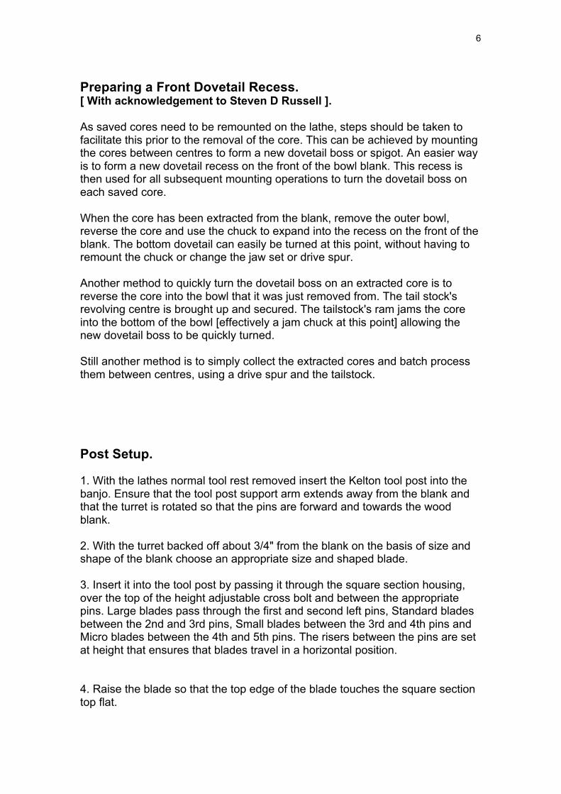
Preparing a Front Dovetail Recess. [ With acknowledgement to Steven D Russell ]. As saved cores need to be remounted on the lathe, steps should be taken to facilitate this prior to the removal of the core. This can be achieved by mounting the cores between centres to form a new dovetail boss or spigot. An easier way is to form a new dovetail recess on the front of the bowl blank. This recess is then used for all subsequent mounting operations to turn the dovetail boss on each saved core. When the core has been extracted from the blank, remove the outer bowl, reverse the core and use the chuck to expand into the recess on the front of the blank. The bottom dovetail can easily be turned at this point, without having to remount the chuck or change the jaw set or drive spur. Another method to quickly turn the dovetail boss on an extracted core is to reverse the core into the bowl that it was just removed from. The tail stock's revolving centre is brought up and secured. The tailstock's ram jams the core into the bottom of the bowl [effectively a jam chuck at this point] allowing the new dovetail boss to be quickly turned. Still another method is to simply collect the extracted cores and batch process them between centres, using a drive spur and the tailstock. Post Setup. 1. With the lathes normal tool rest removed insert the Kelton tool post into the banjo. Ensure that the tool post support arm extends away from the blank and that the turret is rotated so that the pins are forward and towards the wood blank. 2. With the turret backed off about 3/4" from the blank on the basis of size and shape of the blank choose an appropriate size and shaped blade. 3. Insert it into the tool post by passing it through the square section housing, over the top of the height adjustable cross bolt and between the appropriate pins. Large blades pass through the first and second left pins, Standard blades between the 2nd and 3rd pins, Small blades between the 3rd and 4th pins and Micro blades between the 4th and 5th pins. The risers between the pins are set at height that ensures that blades travel in a horizontal position. 4. Raise the blade so that the top edge of the blade touches the square section top flat.
7
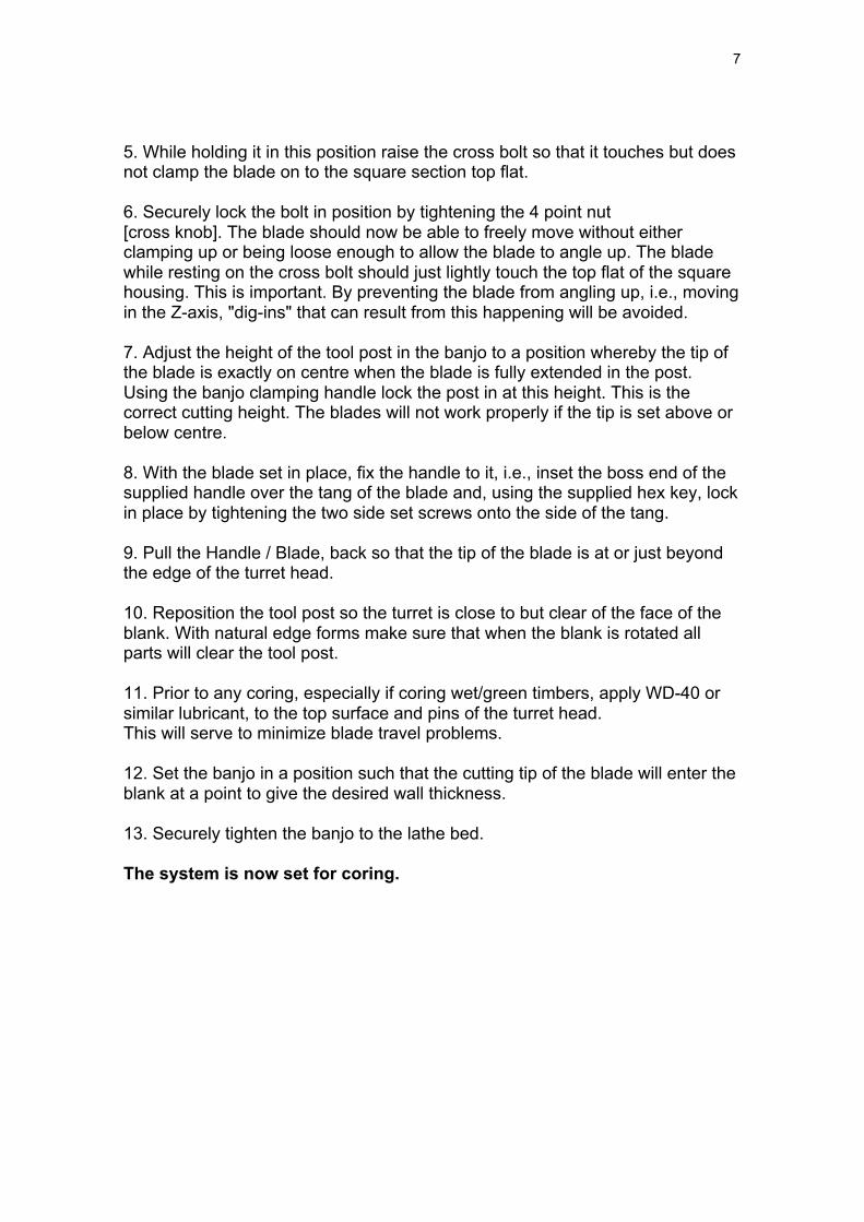
5. While holding it in this position raise the cross bolt so that it touches but does not clamp the blade on to the square section top flat. 6. Securely lock the bolt in position by tightening the 4 point nut [cross knob]. The blade should now be able to freely move without either clamping up or being loose enough to allow the blade to angle up. The blade while resting on the cross bolt should just lightly touch the top flat of the square housing. This is important. By preventing the blade from angling up, i.e., moving in the Z-axis, "dig-ins" that can result from this happening will be avoided. 7. Adjust the height of the tool post in the banjo to a position whereby the tip of the blade is exactly on centre when the blade is fully extended in the post. Using the banjo clamping handle lock the post in at this height. This is the correct cutting height. The blades will not work properly if the tip is set above or below centre. 8. With the blade set in place, fix the handle to it, i.e., inset the boss end of the supplied handle over the tang of the blade and, using the supplied hex key, lock in place by tightening the two side set screws onto the side of the tang. 9. Pull the Handle / Blade, back so that the tip of the blade is at or just beyond the edge of the turret head. 10. Reposition the tool post so the turret is close to but clear of the face of the blank. With natural edge forms make sure that when the blank is rotated all parts will clear the tool post. 11. Prior to any coring, especially if coring wet/green timbers, apply WD-40 or similar lubricant, to the top surface and pins of the turret head. This will serve to minimize blade travel problems. 12. Set the banjo in a position such that the cutting tip of the blade will enter the blank at a point to give the desired wall thickness. 13. Securely tighten the banjo to the lathe bed. The system is now set for coring.

8
Aiming the Blade. When coring it is important to be able to accurately "aim" or sight the blade. Failure to do this can result in the blade penetrating the side of the blank. There are a number of ways to do this. A simple but effective technique is Steven D. Russell's " complementary arc sighting process" [Points 1 - 4 are quoted from his "Learn to Master the Kel McNaughton System"]. 1. With the blade, tool post and banjo set as describe above set the tip of the blade at the desired wall thickness on the front face of the blank. 2. Whilst sighting the bowls exterior curve [left side] from above, move the curved blade into a position that closely matches the exterior curve of the bowl wall and lock the banjo into position. 3. When the two curves [exterior bowl curve and interior blade curve] match your presentation will follow that preset penetration arc. 4. Since you have already set the desired wall thickness, the complimentary arcs will insure a successful coring, virtually eliminating the possibility of thin or thick bottoms on your saved bowl. 5. Note: As the tip of the tool is in line with the handle sighting down the handle indicates the distance cut at any stage of the coring. Note: The Kel McNaughton Laser Handle Guide, available as a separate accessory, allows for cutting tip position to be determined with pinpoint accuracy.
9
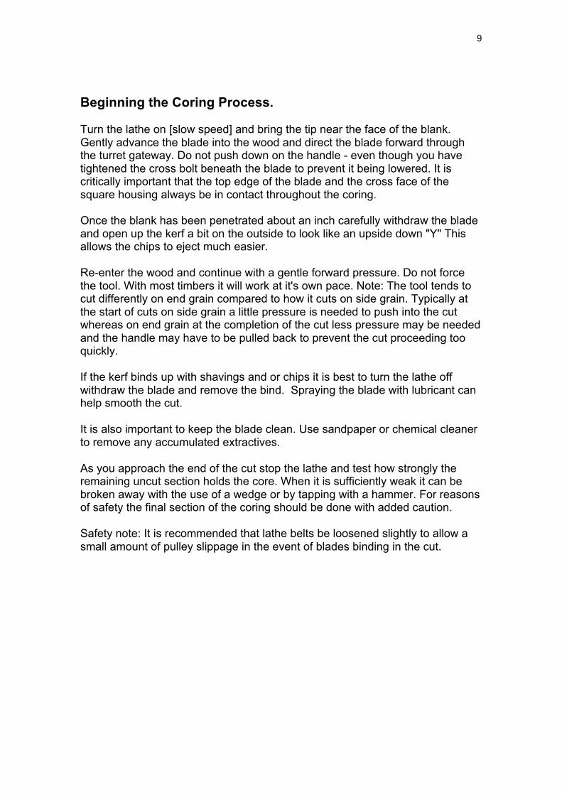
Beginning the Coring Process. Turn the lathe on [slow speed] and bring the tip near the face of the blank. Gently advance the blade into the wood and direct the blade forward through the turret gateway. Do not push down on the handle - even though you have tightened the cross bolt beneath the blade to prevent it being lowered. It is critically important that the top edge of the blade and the cross face of the square housing always be in contact throughout the coring. Once the blank has been penetrated about an inch carefully withdraw the blade and open up the kerf a bit on the outside to look like an upside down "Y" This allows the chips to eject much easier. Re-enter the wood and continue with a gentle forward pressure. Do not force the tool. With most timbers it will work at it's own pace. Note: The tool tends to cut differently on end grain compared to how it cuts on side grain. Typically at the start of cuts on side grain a little pressure is needed to push into the cut whereas on end grain at the completion of the cut less pressure may be needed and the handle may have to be pulled back to prevent the cut proceeding too quickly. If the kerf binds up with shavings and or chips it is best to turn the lathe off withdraw the blade and remove the bind. Spraying the blade with lubricant can help smooth the cut. It is also important to keep the blade clean. Use sandpaper or chemical cleaner to remove any accumulated extractives. As you approach the end of the cut stop the lathe and test how strongly the remaining uncut section holds the core. When it is sufficiently weak it can be broken away with the use of a wedge or by tapping with a hammer. For reasons of safety the final section of the coring should be done with added caution. Safety note: It is recommended that lathe belts be loosened slightly to allow a small amount of pulley slippage in the event of blades binding in the cut.
10
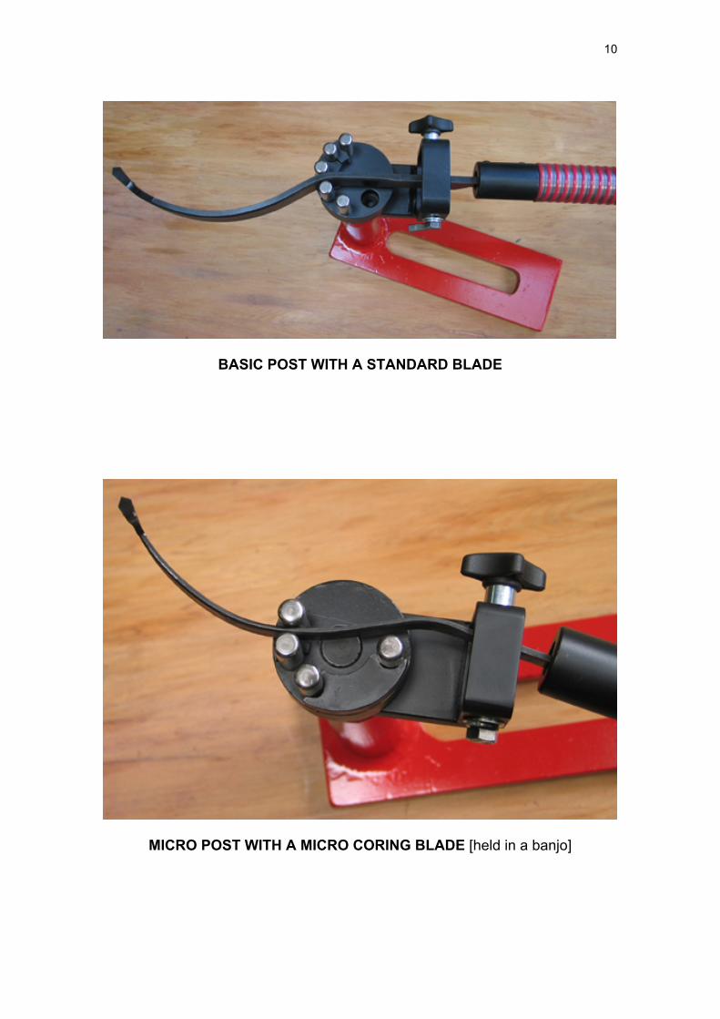
BASIC POST WITH A STANDARD BLADE
MICRO POST WITH A MICRO CORING BLADE [held in a banjo]
11
TOOL SHARPENING When sharpening try to retain the blades original proportions and angles - clearances are important. The configuration of the cutting tip is one designed by U.S.A. turner Mike Mahoney [see Mike Mahoney DVD "Mike Mahoney on the McNaughton Center Saver"]. The tool cuts by way of the raised burr at the cutting edge. A few upward wipes with a good stone, e.g., an Akansas, will maintain this burr. [Ordinary slip stones are considerably more effective than diamond ones]. When using these try not to round the burr over. The sharpening movement should be one in which the stone is moved up the face of the blade and then, as it reaches the end of the wipe, moved away. Very occasionally when the tips will need a more substantial sharpening with e.g., a bench grinder or linisher, only a very light contact needs to be made - just sufficient to raise a new burr. Using The Kel McNaughton System on Low Powered Lathes. The "Fluid-Pulse" technique developed by Steven D.Russell allows the system to be used on low powered lathes. As above use light pressure to start the cut and make the upside-down "Y" in the face of the parting cut to help with chip/shaving ejection. Re-enter the part and move the blade forward until it just touches the wood and begins cutting. Advance the blade forward and begin cutting. The speed of the advance will be determined by the motor size. When you see/feel/hear the motor starting to loose revs with care slightly withdraw the blade from the cutting edge. The blade is not withdrawn from the part, only slightly withdrawn until it stops cutting. The revs will pick up again. When they do, re-enter the cut. When you feel the cut beginning to slow again withdraw enough so that actual cutting ceases and then re-enter as the revs pick up. The action is one of fluid pulse... push gently into the cut until the motor starts to loose revs, withdraw slightly then re-enter the cut. The action becomes fluid through the in and out pulses of the blade.
12
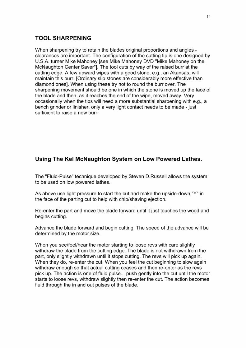
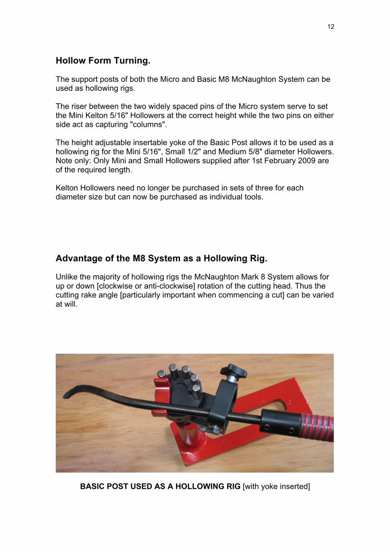
Hollow Form Turning. The support posts of both the Micro and Basic M8 McNaughton System can be used as hollowing rigs. The riser between the two widely spaced pins of the Micro system serve to set the Mini Kelton 5/16" Hollowers at the correct height while the two pins on either side act as capturing "columns". The height adjustable insertable yoke of the Basic Post allows it to be used as a hollowing rig for the Mini 5/16", Small 1/2" and Medium 5/8" diameter Hollowers. Note only: Only Mini and Small Hollowers supplied after 1st February 2009 are of the required length. Kelton Hollowers need no longer be purchased in sets of three for each diameter size but can now be purchased as individual tools. Advantage of the M8 System as a Hollowing Rig. Unlike the majority of hollowing rigs the McNaughton Mark 8 System allows for up or down [clockwise or anti-clockwise] rotation of the cutting head. Thus the cutting rake angle [particularly important when commencing a cut] can be varied at will.
BASIC POST USED AS A HOLLOWING RIG [with yoke inserted]
13
MICRO POST USED AS A HOLLOWING RIG [held in a banjo]
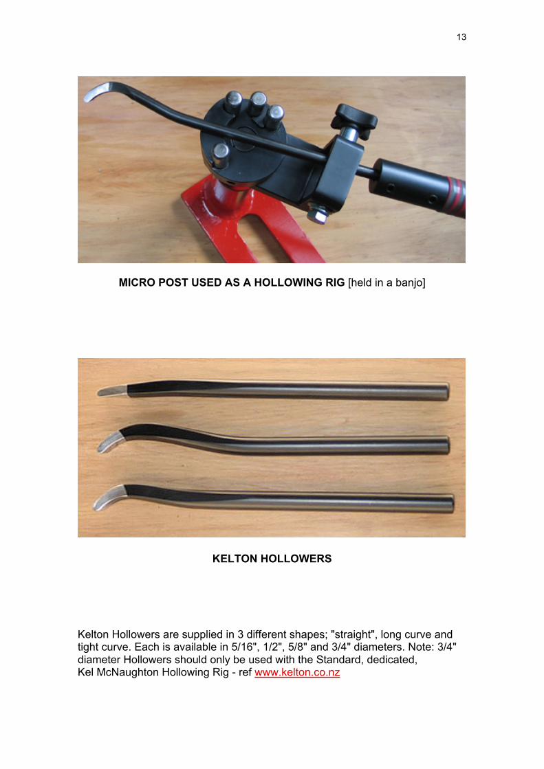
KELTON HOLLOWERS
Kelton Hollowers are supplied in 3 different shapes; "straight", long curve and tight curve. Each is available in 5/16", 1/2", 5/8" and 3/4" diameters. Note: 3/4" diameter Hollowers should only be used with the Standard, dedicated, Kel McNaughton Hollowing Rig - ref www.kelton.co.nz

14
Purchasing Options. All components of the Kel McNaughton Basic M 8, the Micro Systems and all Hollowers may be individually purchased. Safety. When using the McNaughton System observe all normal woodturning safety procedures. Out of balance blanks can generate substantially greater forces than normal turning. Always make sure that your blank is reasonably balanced and very securely held. Use the system only on lathes with strong well made banjos. Weak or unsubstantial banjos should be replaced with ones that are of adequate structural strength. Acknowledgement. In the writing of this guide Kelton Industries gratefully acknowledges the contribution of U.S.A. turner Steven D. Russell. Much of the information has been taken directly from his "Learn to Master the McNaughton Centre Saver System" See WoodturningVideosPlus.com See www.kelton.co.nz for more information on the Mark 8 McNaughton System and other Kelton products.