the lens law - cnr · the lens law an autofocus mechanism introduction an autofocus mechanism is a...
TRANSCRIPT
THE LENS LAW AN AUTOFOCUS MECHANISM
INTRODUCTION
An autofocus mechanism is a device which allows to change the magnification of an optical system by
moving the object, image plane and even the lens, still maintaining the image always at focus.
This task can be accomplished by using a simple mechanical device, a sort of an analog computer.
Three techniques are reported here: the three hinged rods, the endless belt, and the sliding rods
mechanisms.
These mechanical autofocus mechanisms are used in some photographic enlarger and photocopier.
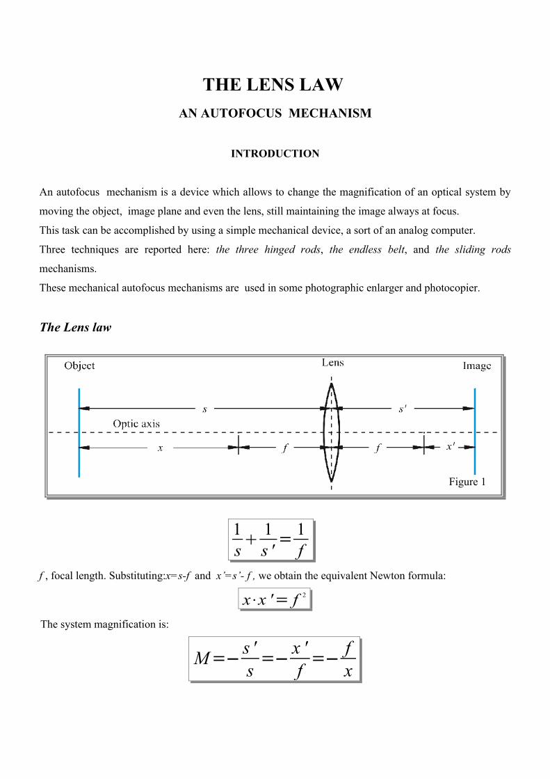
The Lens law
1s
1s ' =
1f
f , focal length. Substituting:x=s-f and x’=s’- f , we obtain the equivalent Newton formula:
x⋅x '= f 2
The system magnification is:
M=− s 's =− x '
f =− fx
Figure 1
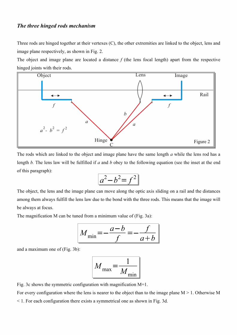
The three hinged rods mechanism
Three rods are hinged together at their vertexes (C), the other extremities are linked to the object, lens and
image plane respectively, as shown in Fig. 2.
The object and image plane are located a distance f (the lens focal length) apart from the respective
hinged joints with their rods.
The rods which are linked to the object and image plane have the same length a while the lens rod has a
length b. The lens law will be fulfilled if a and b obey to the following equation (see the inset at the end
of this paragraph):
The object, the lens and the image plane can move along the optic axis sliding on a rail and the distances
among them always fulfill the lens law due to the bond with the three rods. This means that the image will
be always at focus.
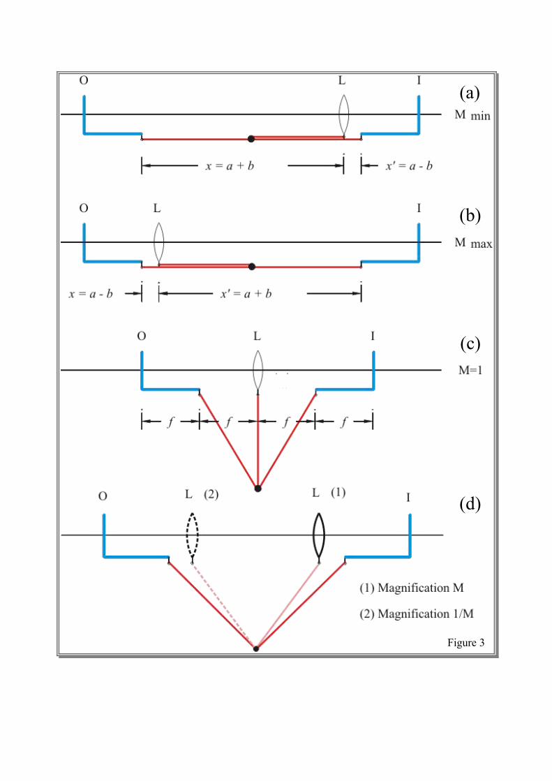
The magnification M can be tuned from a minimum value of (Fig. 3a):
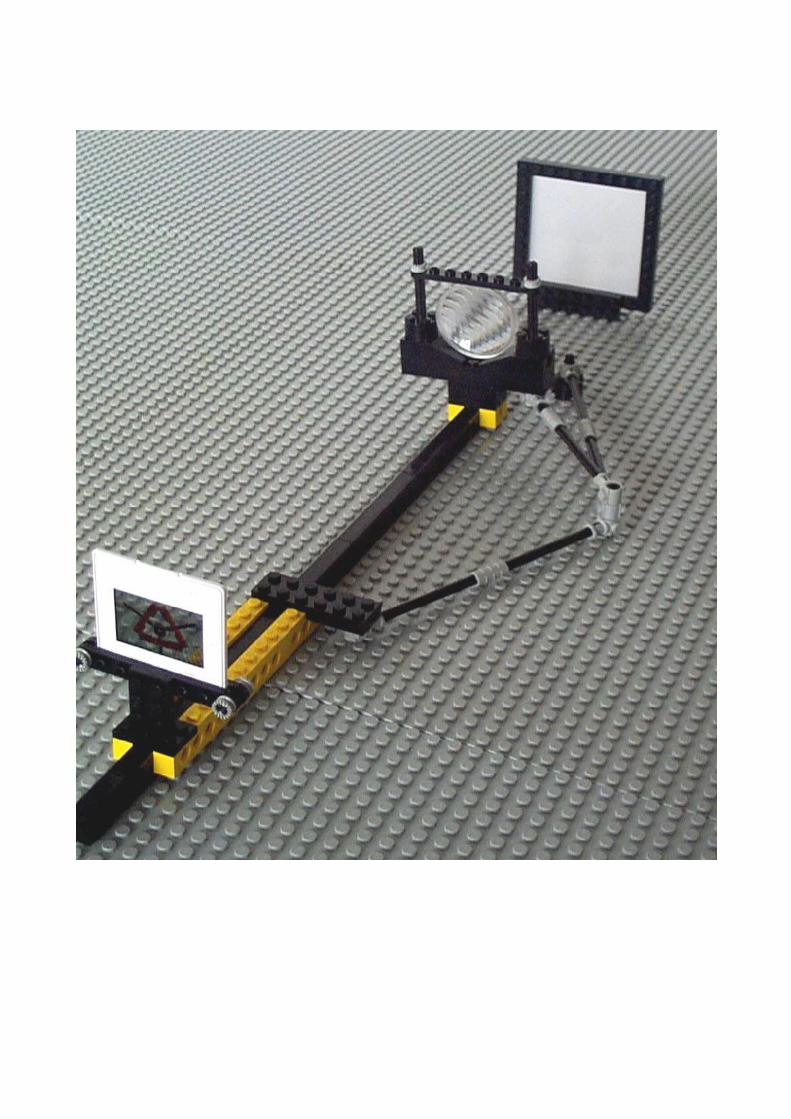
and a maximum one of (Fig. 3b):
Fig. 3c shows the symmetric configuration with magnification M=1.
For every configuration where the lens is nearer to the object than to the image plane M > 1. Otherwise M
< 1. For each configuration there exists a symmetrical one as shown in Fig. 3d.
Figure 2
a2−b2= f 2
M min=−a−bf =− f
ab
M max=1
M min
(d)
(b)
(c)
(a)
Figure 3
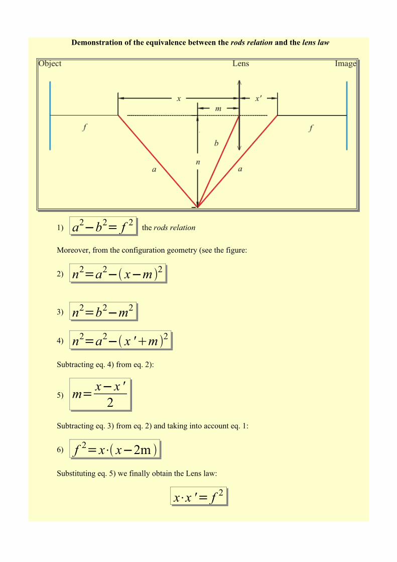
Demonstration of the equivalence between the rods relation and the lens law
1) a2−b2= f 2 the rods relation
Moreover, from the configuration geometry (see the figure:
2) n2=a2− x−m 2
3) n2=b2−m2
4) n2=a2− x 'm 2
Subtracting eq. 4) from eq. 2):
5) m= x−x '2
Subtracting eq. 3) from eq. 2) and taking into account eq. 1:
6) f 2=x⋅ x−2m
Substituting eq. 5) we finally obtain the Lens law:
x⋅x '= f 2
Other autofocus mechanisms
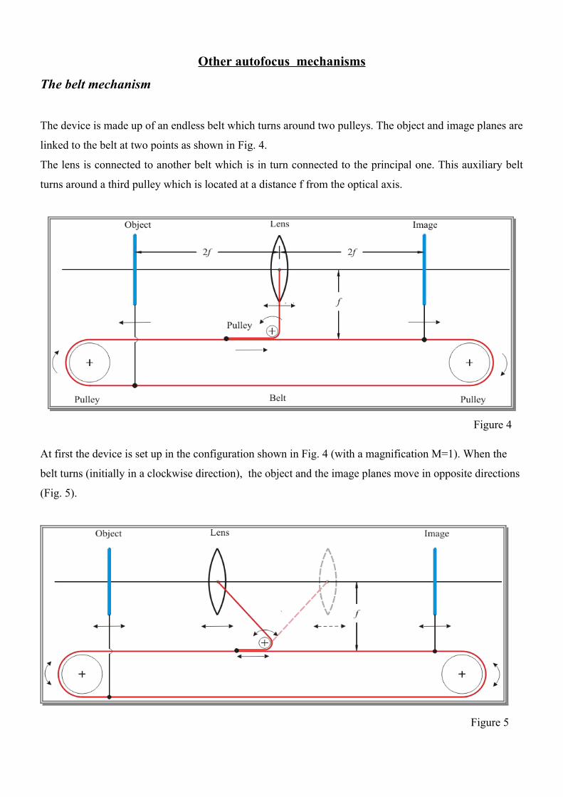
The belt mechanism
The device is made up of an endless belt which turns around two pulleys. The object and image planes are
linked to the belt at two points as shown in Fig. 4.
The lens is connected to another belt which is in turn connected to the principal one. This auxiliary belt
turns around a third pulley which is located at a distance f from the optical axis.
Figure 4
At first the device is set up in the configuration shown in Fig. 4 (with a magnification M=1). When the
belt turns (initially in a clockwise direction), the object and the image planes move in opposite directions
(Fig. 5).
Figure 5
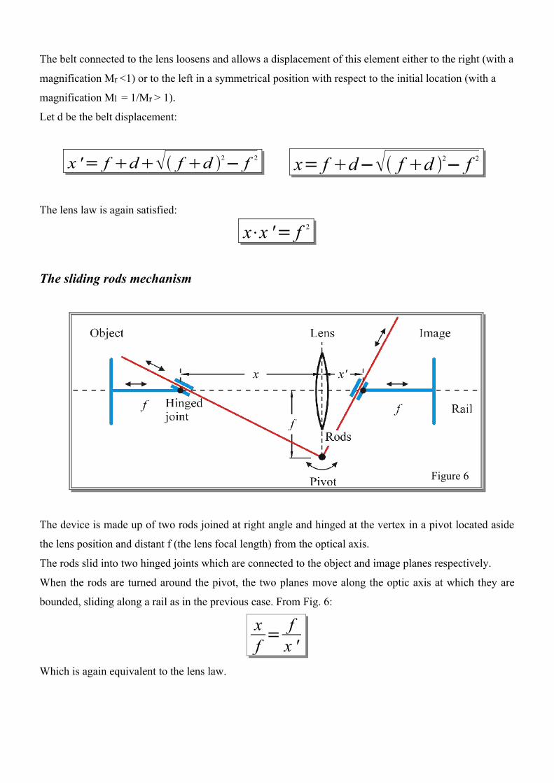
The belt connected to the lens loosens and allows a displacement of this element either to the right (with a
magnification Mr <1) or to the left in a symmetrical position with respect to the initial location (with a
magnification Ml = 1/Mr > 1).
Let d be the belt displacement:
x '= f d f d 2− f 2 x= f d− f d 2− f 2
The lens law is again satisfied:
The sliding rods mechanism
The device is made up of two rods joined at right angle and hinged at the vertex in a pivot located aside
the lens position and distant f (the lens focal length) from the optical axis.
The rods slid into two hinged joints which are connected to the object and image planes respectively.
When the rods are turned around the pivot, the two planes move along the optic axis at which they are
bounded, sliding along a rail as in the previous case. From Fig. 6:
xf =
fx '
Which is again equivalent to the lens law.
x⋅x '= f 2
Figure 6
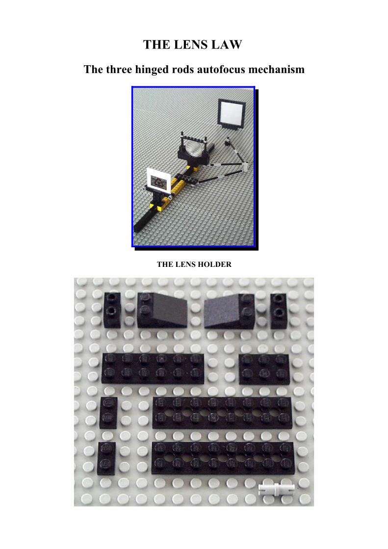
THE LENS LAW
The three hinged rods autofocus mechanism
THE LENS HOLDER
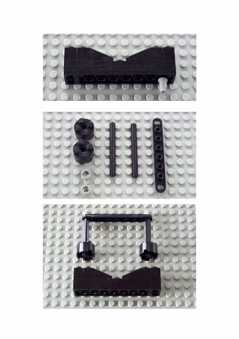
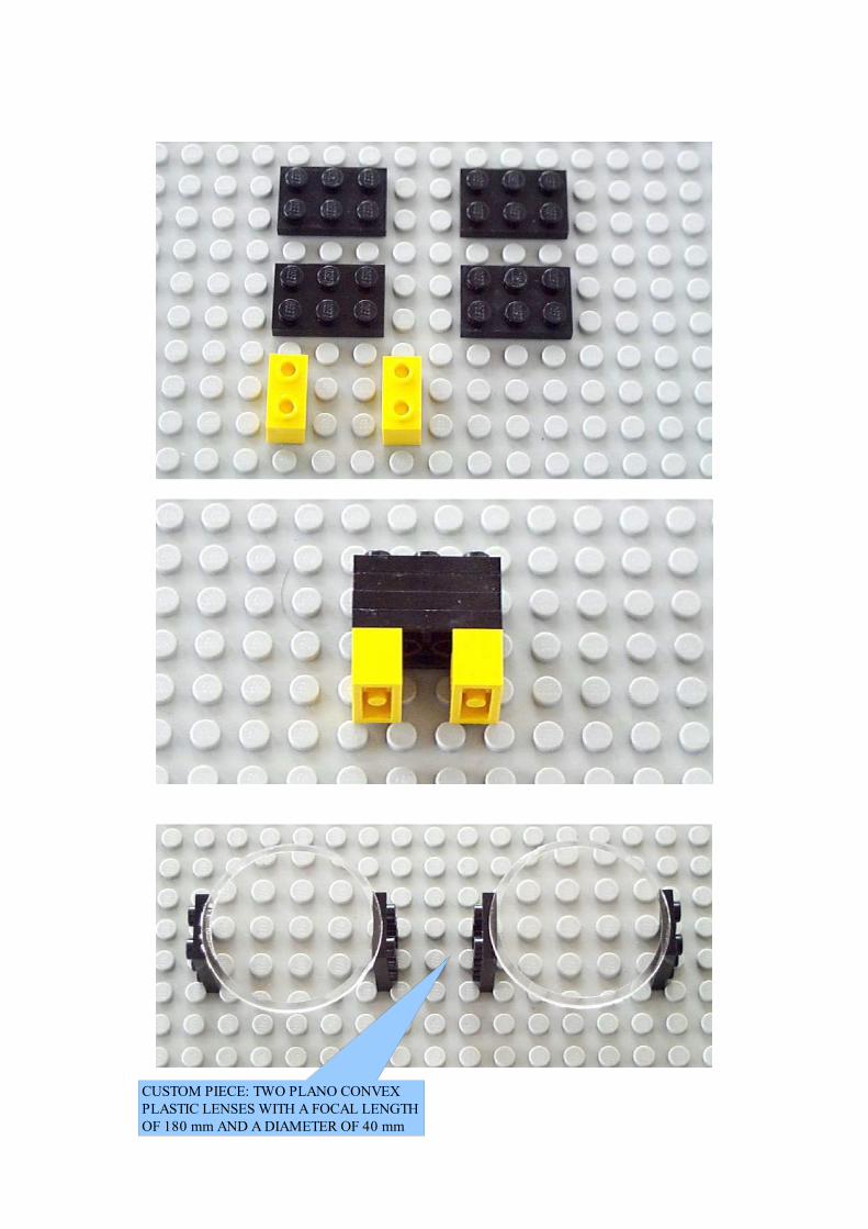
CUSTOM PIECE: TWO PLANO CONVEX PLASTIC LENSES WITH A FOCAL LENGTH OF 180 mm AND A DIAMETER OF 40 mm
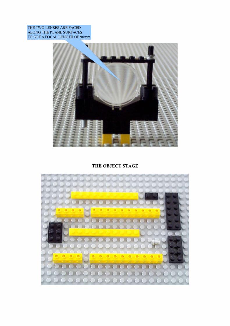
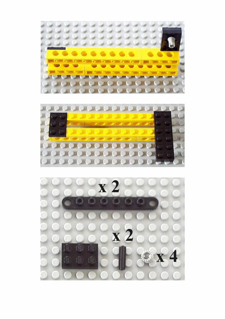
THE OBJECT STAGE
THE TWO LENSES ARE FACED ALONG THE PLANE SURFACES TO GET A FOCAL LENGTH OF 90mm
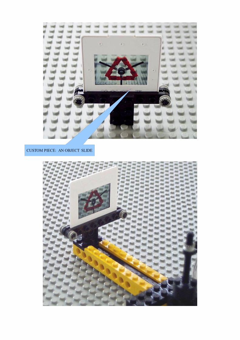
CUSTOM PIECE: AN OBJECT SLIDE

THE IMAGE PLANE
CUSTOM PIECE: A PAPER PROJECTION SCREEN
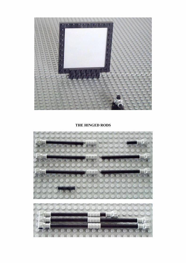
THE HINGED RODS
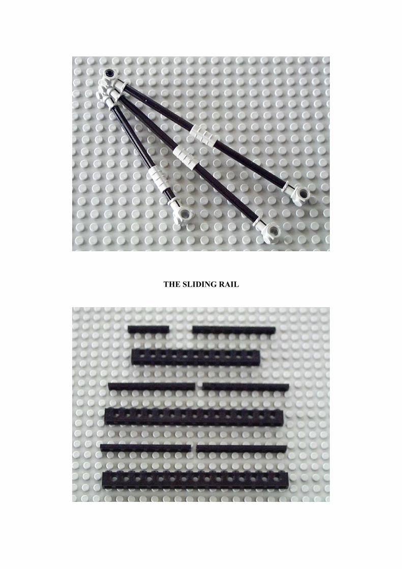
THE SLIDING RAIL
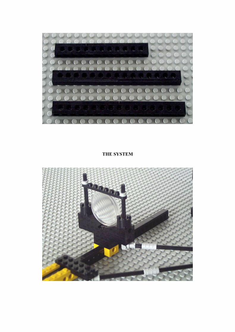
THE SYSTEM
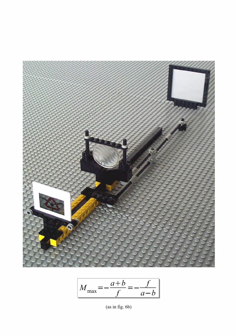
M max=−abf =− f
a−b(as in fig. 6b)

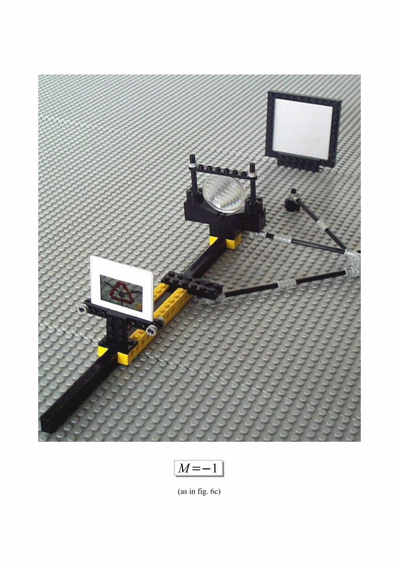
M=−1(as in fig. 6c)
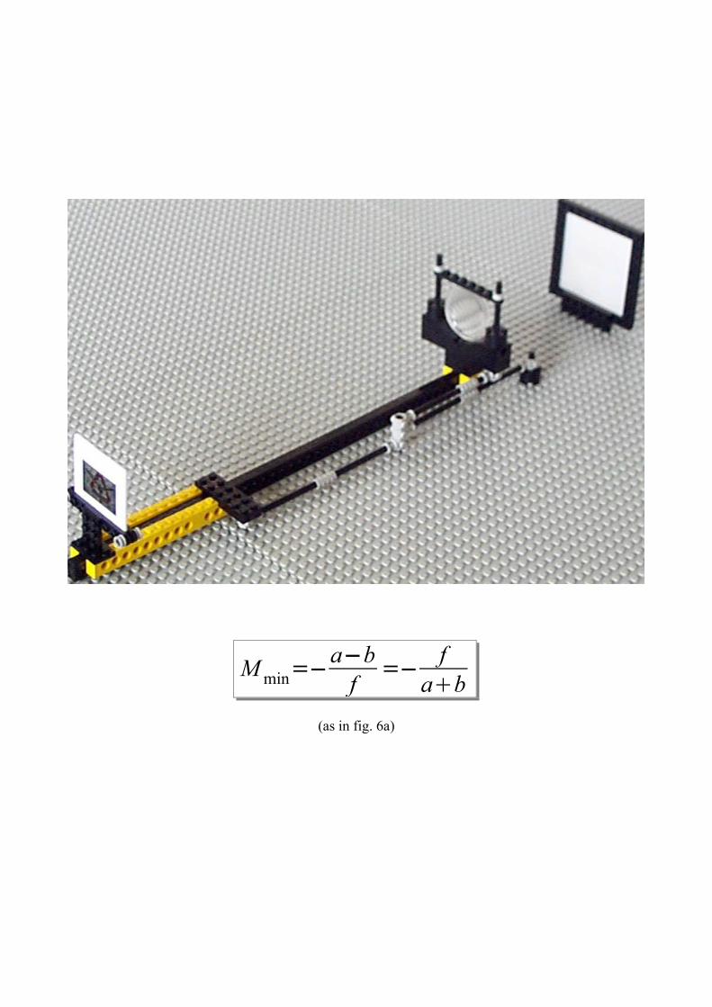
(as in fig. 6a)
M min=−a−bf =− f
ab
COMMENTS AND CONCLUSIONS
An improvement of this set up was realized (but unfortunately there is no documentation
about that) with the use of the mindstorm technology. A motor moved the optical elements
periodically changing the magnification from Mmin to Mmax and back again. Two touch
sensors were used at the two travel range ends to reverse the movement direction. A light
sensor was used to detect the midrange position to pause the movement for some time at
magnification M=1. A lamp and a collimating lens were used to illuminate the object slide
from behind. All the process was controlled by the RCX brick.
Three autofocus techniques are reported in the introduction: the three hinged rods, the
endless belt, and the sliding rods mechanisms. Though only the three hinged rods
mechanism has been realized with LEGO, the other two mechanisms could be easily
realized as well.
It will be interesting to stress that the three hinged rods mechanism derives from the
Peaucellier linkage (or P. cell or P. inversor) ( http://en.wikipedia.org/wiki/Peaucellier-
Lipkin_linkage or, a LEGO version: http://staff.science.uva.nl/~leo/lego/peaucellier.html)
In conclusions, this experience could be a valuable kit to teach the lens law and even to
introduce the concept of analog computers, showing how some mechanical device can
perform some sort of computing to solve equations (this time the lens law equation) (see
for example http://en.wikipedia.org/wiki/Analog_computer).