the maxi-joint company. · general rubber’s maxi-joint® wide arch expansion joints provide...
TRANSCRIPT
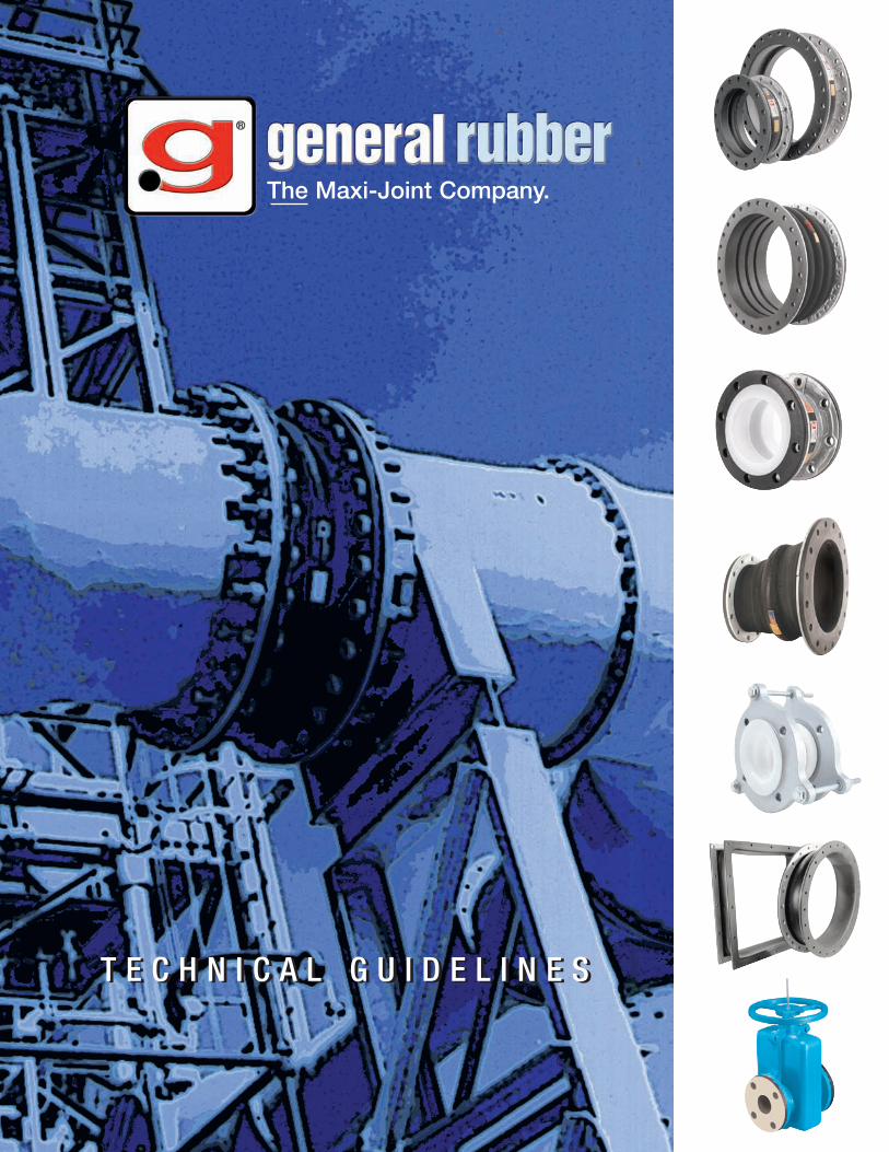
The Maxi-Joint Company.
T E C H N I C A L G U I D E L I N E ST E C H N I C A L G U I D E L I N E S
Style 1101ER is aneconomic and space-saving way to combine aneccentric pipe fitting withan expansion joint.
Style 3303 - MoldedTeflon® design offerssuperior chemicalresistance with lowdeflection forces.
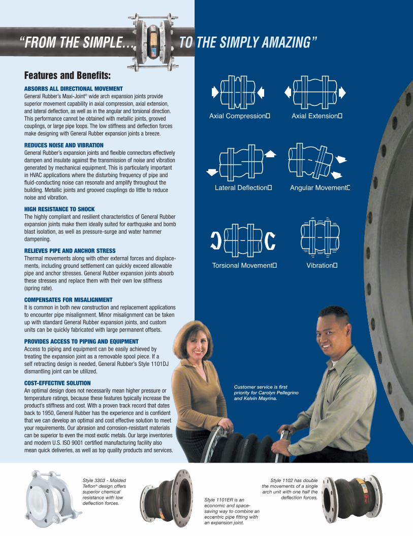
Features and Benefits:ABSORBS ALL DIRECTIONAL MOVEMENTGeneral Rubber’s Maxi-Joint® wide arch expansion joints providesuperior movement capability in axial compression, axial extension,and lateral deflection, as well as in the angular and torsional direction.This performance cannot be obtained with metallic joints, groovedcouplings, or large pipe loops. The low stiffness and deflection forcesmake designing with General Rubber expansion joints a breeze.
REDUCES NOISE AND VIBRATIONGeneral Rubber’s expansion joints and flexible connectors effectivelydampen and insulate against the transmission of noise and vibrationgenerated by mechanical equipment. This is particularly importantin HVAC applications where the disturbing frequency of pipe andfluid-conducting noise can resonate and amplify throughout thebuilding. Metallic joints and grooved couplings do little to reducenoise and vibration.
HIGH RESISTANCE TO SHOCKThe highly compliant and resilient characteristics of General Rubberexpansion joints make them ideally suited for earthquake and bombblast isolation, as well as pressure-surge and water hammerdampening.
RELIEVES PIPE AND ANCHOR STRESSThermal movements along with other external forces and displace-ments, including ground settlement can quickly exceed allowablepipe and anchor stresses. General Rubber expansion joints absorbthese stresses and replace them with their own low stiffness(spring rate).
COMPENSATES FOR MISALIGNMENTIt is common in both new construction and replacement applicationsto encounter pipe misalignment. Minor misalignment can be takenup with standard General Rubber expansion joints, and customunits can be quickly fabricated with large permanent offsets.
PROVIDES ACCESS TO PIPING AND EQUIPMENTAccess to piping and equipment can be easily achieved bytreating the expansion joint as a removable spool piece. If aself retracting design is needed, General Rubber’s Style 1101DJdismantling joint can be utilized.
COST-EFFECTIVE SOLUTIONAn optimal design does not necessarily mean higher pressure ortemperature ratings, because these features typically increase theproduct’s stiffness and cost. With a proven track record that datesback to 1950, General Rubber has the experience and is confidentthat we can develop an optimal and cost effective solution to meetyour requirements. Our abrasion and corrosion-resistant materialscan be superior to even the most exotic metals. Our large inventoriesand modern U.S. ISO 9001 certified manufacturing facility alsomean quick deliveries, as well as top quality products and services.
Axial Extension
T
Axial Compression
Lateral Deflection
V
Angular Movement
A
Torsional Movement Vibration
A
Style 1102 has doublethe movements of a singlearch unit with one half the
deflection forces.
Customer service is firstpriority for Carolyn Pellegrinoand Kelvin Mayrina.
“FROM THE SIMPLE... TO THE SIMPLY AMAZING”
Style 1015T Teflon®-LinedMaxi-Joint® has superiorchemical resistance evenat higher temperaturesand pressures.
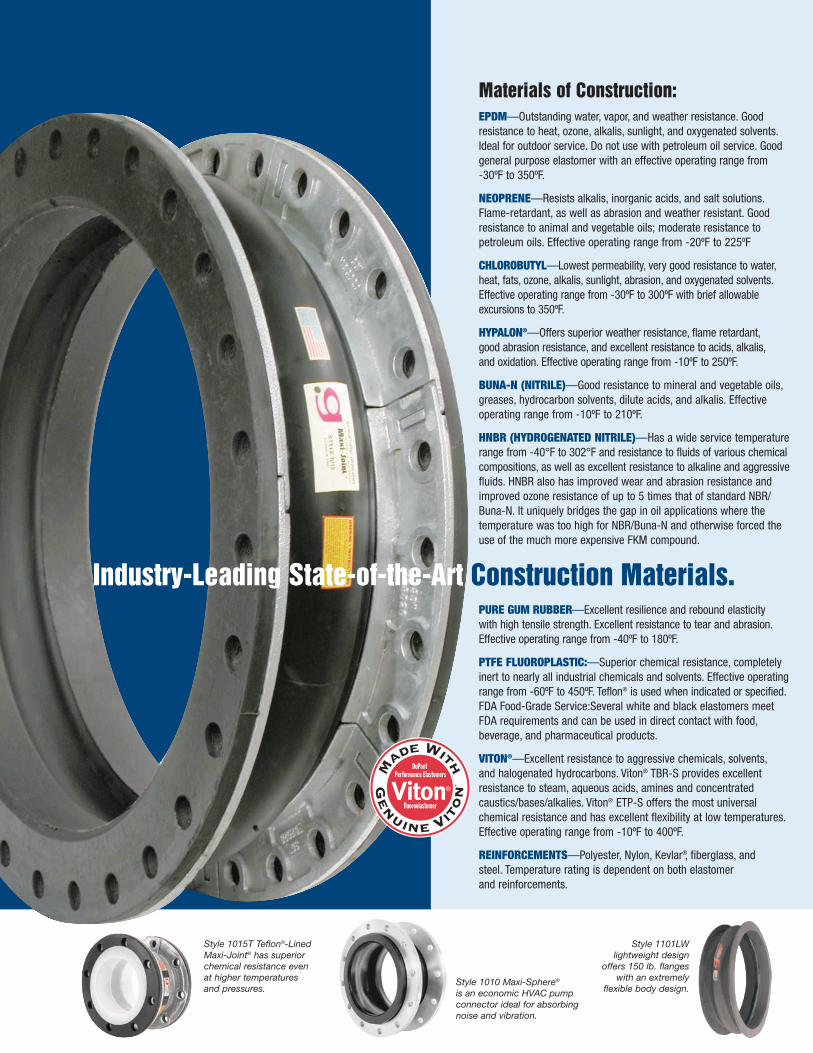
Industry-Leading State-of-the-Art Construction Materials.
Style 1101LWlightweight design
offers 150 lb. flangeswith an extremely
flexible body design.Style 1010 Maxi-Sphere®
is an economic HVAC pumpconnector ideal for absorbingnoise and vibration.
®
Materials of Construction:EPDM—Outstanding water, vapor, and weather resistance. Goodresistance to heat, ozone, alkalis, sunlight, and oxygenated solvents.Ideal for outdoor service. Do not use with petroleum oil service. Goodgeneral purpose elastomer with an effective operating range from-30ºF to 350ºF.
NEOPRENE—Resists alkalis, inorganic acids, and salt solutions.Flame-retardant, as well as abrasion and weather resistant. Goodresistance to animal and vegetable oils; moderate resistance topetroleum oils. Effective operating range from -20ºF to 225ºF
CHLOROBUTYL—Lowest permeability, very good resistance to water,heat, fats, ozone, alkalis, sunlight, abrasion, and oxygenated solvents.Effective operating range from -30ºF to 300ºF with brief allowableexcursions to 350ºF.
HYPALON®—Offers superior weather resistance, flame retardant,good abrasion resistance, and excellent resistance to acids, alkalis,and oxidation. Effective operating range from -10ºF to 250ºF.
BUNA-N (NITRILE)—Good resistance to mineral and vegetable oils,greases, hydrocarbon solvents, dilute acids, and alkalis. Effectiveoperating range from -10ºF to 210ºF.
HNBR (HYDROGENATED NITRILE)—Has a wide service temperaturerange from -40°F to 302°F and resistance to fluids of various chemicalcompositions, as well as excellent resistance to alkaline and aggressivefluids. HNBR also has improved wear and abrasion resistance andimproved ozone resistance of up to 5 times that of standard NBR/Buna-N. It uniquely bridges the gap in oil applications where thetemperature was too high for NBR/Buna-N and otherwise forced theuse of the much more expensive FKM compound.
PURE GUM RUBBER—Excellent resilience and rebound elasticitywith high tensile strength. Excellent resistance to tear and abrasion.Effective operating range from -40ºF to 180ºF.
PTFE FLUOROPLASTIC:—Superior chemical resistance, completelyinert to nearly all industrial chemicals and solvents. Effective operatingrange from -60ºF to 450ºF. Teflon® is used when indicated or specified.FDA Food-Grade Service:Several white and black elastomers meetFDA requirements and can be used in direct contact with food,beverage, and pharmaceutical products.
VITON®—Excellent resistance to aggressive chemicals, solvents,and halogenated hydrocarbons. Viton® TBR-S provides excellentresistance to steam, aqueous acids, amines and concentratedcaustics/bases/alkalies. Viton® ETP-S offers the most universalchemical resistance and has excellent flexibility at low temperatures.Effective operating range from -10ºF to 400ºF.
REINFORCEMENTS—Polyester, Nylon, Kevlar®, fiberglass, andsteel. Temperature rating is dependent on both elastomerand reinforcements.

F/F
I.D.
O.D.
TH
Hot DippedGalvanizedRetaining Rings
1/4" MinimumThicknessLeakproofElastomer Tube
Multiple Layersof Tire CordReinforcement
Control Unit(See Note 5)
Optional Filled ArchConstruction
Also Typical forOther Styles
Notes:1.) All parts listed are designed for 30" Hg (full vacuum) and have a maximum test at 26" Hg due to facility altitude and equipment
limitations.2.) Maximum operating temperature of 250ºF for EPDM, Butyl, Hypalon®, and Viton®; 225ºF for Neoprene; 210ºF for Nitrile; 180ºF
for Pure Gum Rubber; 300ºF for EPDM and Butyl in air service at 25 PSI maximum; higher pressure and temperature ratingsavailable.
3.) All sizes can be supplied with a filled arch reducing their movements by 50% and increasing the spring rates fourfold.4.) For full product specifications and installation instructions, see SPEC 1015-1, SPEC 1015T-1 and ININ 1015-1, ININ 1015T-1.
Gross weights include retaining rings.
5.) WARNING: Control units (sold separately) must be used when piping is not properly anchored. Number of rods are dependentupon maximum field test pressures. Expansion joints may operate in pipelines carrying fluids at elevated temperatures and pres-sures, so precaution should be taken to ensure proper installation and regular inspection. Care is required to protect personnelin the event of leakage or splash. Adequate floor drains are always recommended.
6.) Movements are non-concurrent. Contact General Rubber for concurrent movements, and for sizes not shown up to 144" I.D.7.) Retaining rings are typically “L” shaped for sizes 1” through 16”, and can be flat depending on internal reinforcements and for
sizes 18” and larger.8.) Standard 125/150 lb. drilling includes, 1"-24" with ANSI B16.1 Class 125 lb./B16.5 Class 150 lb., 30"-60" with ANSI B16.1 Class
125 lb./ B16.47 series A, Class 150 lb., 72"-108" with ANSI B16.1 Class 125 lb./ AWWA C207 Class B.
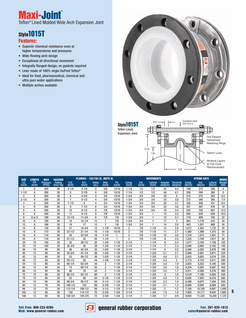
Maxi-Joint®
Molded Wide Arch Expansion Joint
Style1015Features:• Wide flowing arch design• Exceptional all directional movement capability• Virtually eliminates sediment buildup• Higher pressure rating than conventional expansion joints• Excellent chemical and abrasion resistance• Full vacuum rating (30" Hg) in all sizes• 250ºF continuous service standard, 400ºF available• Filled arch design available• Economical fully molded construction• Standard face to face dimensions with
ANSI 125/150 lb. drilling• Hot dipped galvanized retaining rings standard• Absorbs noise, vibration and shock• Compensates for minor misalignment and offset• Low stiffness and deflection forces• Integrally flanged design, no gaskets required• Large inventory means quick shipments• Simple to install, lightweight and high strength• Provides easy access to piping and equipment• Wide variety of tube and cover elastomers
available, including Pure Gum Rubber, EPDM,Neoprene, Butyl, Nitrile, Hypalon®, Viton®,Teflon®, Food Grade, and more
general rubber corporationWeb: www.general-rubber.com [email protected] Free: 800-233-6294 Fax: 201-935-1915
4
Style1015Single (1) Wide Arch,Spool Type, Expansion Joint
5
general rubber corporationWeb: www.general-rubber.com [email protected] Free: 800-233-6294 Fax: 201-935-1915
SIZE LENGTH MAX VACUUM FLANGES - 125/150 LB. (NOTE 8) MOVEMENTS SPRING RATE GROSSI.D. F/F Pressure Rating O.D. B.C. Holes Hole TH. Comp. Ext. Lateral Angular Torsional Comp. Ext. Lateral Weight
(inch) (inch) (PSIG) (inch Hg) (inch) (inch) (no.) (inch) (inch) (inch) (inch) (inch) (degree) (degree) (lbs/in) (lbs/in) (lbs/in) (lbs)1 6 200 30 4-1/4 3-1/8 4 5/8 13/16 1-1/4 1/2 1/2 50 4.4 199 272 368 4
1-1/2 6 200 30 5 3-7/8 4 5/8 13/16 1-1/4 1/2 1/2 44 4.1 208 294 365 52 6 200 30 6 4-3/4 4 3/4 13/16 1-3/4 3/4 3/4 39 4 214 272 363 5.5
2-1/2 6 200 30 7 5-1/2 4 3/4 13/16 1-3/4 3/4 3/4 33 3.8 272 340 385 7.53 6 200 30 7-1/2 6 4 3/4 13/16 1-3/4 3/4 3/4 28 3.7 320 408 431 8.54 6 200 30 9 7-1/2 8 3/4 13/16 1-3/4 3/4 3/4 22 3.6 437 567 476 105 6 200 30 10 8-1/2 8 7/8 13/16 1-3/4 3/4 3/4 18 3.4 534 703 567 12.56 6 200 30 11 9-1/2 8 7/8 13/16 1-3/4 3/4 1 15 3.2 650 839 629 16.58 6 or 8 190 30 13-1/2 11-3/4 8 7/8 7/8 1-3/4 3/4 1 12 3.1 719 929 765 22
10 8 190 30 16 14-1/4 12 1 7/8 1-3/4 3/4 1 17 3 903 1,179 816 3412 8 190 30 19 17 12 1 7/8 1-3/4 3/4 1 14 2.9 943 1,247 969 4514 8 130 30 21 18-3/4 12 1-1/8 15/16 2 7/8 1-1/8 12 2.8 1,012 1,302 1,133 5516 8 110 30 23-1/2 21-1/4 16 1-1/8 15/16 2 7/8 1-1/8 11 2.7 1,080 1,399 1,315 6418 8 110 30 25 22-3/4 16 1-1/4 1 2 7/8 1-1/8 10 2.6 1,216 1,573 1,451 7120 8 110 30 27-1/2 25 20 1-1/4 1 2 7/8 1-1/8 9 2.5 1,225 1,749 1,617 8224 10 100 30 32 29-1/2 20 1-3/8 1-1/8 2-1/4 1 1-1/4 8 2.4 1,617 2,108 1,738 10230 10 100 30 38-3/4 36 28 1-3/8 1-1/8 2-1/4 1 1-1/4 7 2.3 2,040 2,660 2,192 14036 10 90 30 46 42-3/4 32 1-5/8 1-1/8 2-1/4 1 1-1/4 6 2.2 2,494 3,250 2,678 19040 12 80 30 50-3/4 47-1/4 36 1-5/8 1-1/8 2-1/4 1 1-3/8 5.1 2.1 2,698 3,481 2,871 22442 12 80 30 53 49-1/2 36 1-5/8 1-1/8 2-1/4 1 1-3/8 4.8 2.1 2,833 3,655 3,014 23548 12 80 30 59-1/2 56 44 1-5/8 1-1/8 2-1/4 1 1-3/8 4.2 2 3,173 4,153 3,411 29054 12 80 30 66-1/4 62-3/4 44 2 1-1/8 2-1/4 1 1-3/8 3.8 1.9 3,853 5,022 4,140 35060 12 80 30 73 69-1/4 52 2 1-1/8 2-1/4 1 1-3/8 3.6 1.8 4,224 5,565 4,587 42066 12 80 30 80 76 52 2 1-1/8 2-1/4 1 1-3/8 3.3 1.7 4,911 6,398 5,276 46072 12 80 30 86-1/2 82-1/2 60 2 1-1/8 2-1/4 1 1-3/8 3 1.6 5,516 7,186 5,924 53078 12 80 30 93 89 64 2-1/8 1-1/8 2-1/4 1 1-3/8 2.6 1.5 6,000 7,850 6,578 58084 12 80 30 99-3/4 95-1/2 64 2-1/4 1-1/8 2-1/4 1 1-3/8 2.3 1.4 6,498 8,670 7,404 63090 12 70 30 106-1/2 102 68 2-3/8 1-1/8 2-1/4 1 1-3/8 2.1 1.3 6,800 9,200 8,089 85596 12 70 30 113-1/4 108-1/2 68 2-1/2 1-1/8 2-1/4 1 1-3/8 2 1.2 7,156 10,100 9,067 1,000
102 12 60 30 120 114-1/2 72 2-5/8 1-3/8 2-1/4 1 1-3/8 1.8 1.0 7,603 10,711 9,634 1,065108 12 60 30 126-3/4 120-3/4 72 2-5/8 1-3/8 2-1/4 1 1-3/8 1.7 0.9 8,050 11,323 10,200 1,125
F/F
I.D.
O.D.
TH
Hot DippedGalvanizedRetaining Rings
Teflon® Liner
Multiple Layersof Tire CordReinforcement
Control Unit(See Note 5)
Maxi-Joint®
Teflon® Lined Molded Wide Arch Expansion Joint
Style1015TFeatures:• Superior chemical resistance even at
higher temperatures and pressures• Wide flowing arch design• Exceptional all directional movement• Integrally flanged design, no gaskets required• Liner made of 100% virgin DuPont Teflon®
• Ideal for food, pharmaceutical, chemical andultra pure water applications
• Multiple arches available
Style1015TTeflon Lined,Expansion Joint
F/F
I.D.
O.D.
TH
Hot DippedGalvanizedRetaining Rings
1/4" MinimumThicknessLeakproofElastomerTube
Embedded Steeland MultipleLayers of Tire CordReinforcement
Control Unit(See Note 5)
Optional Filled ArchConstruction
Also Typical forOther Styles
2 6 225 30 6 4-3/4 4 3/4 7/8 1 3/4 7/8 1 39 4 270 340 450 72-1/2 6 225 30 7 5-1/2 4 3/4 7/8 1 3/4 7/8 1 33 3.8 340 420 480 8
3 6 225 30 7-1/2 6 4 3/4 7/8 1 3/4 7/8 1 28 3.7 400 510 540 104 6 225 30 9 7-1/2 8 3/4 7/8 1 3/4 7/8 1 22 3.6 550 710 590 145 6 225 30 10 8-1/2 8 7/8 7/8 1 3/4 7/8 1 18 3.4 670 880 710 176 6 225 30 11 9-1/2 8 7/8 7/8 1 3/4 7/8 1 15 3.2 820 1050 790 208 6 225 30 13-1/2 11-3/4 8 7/8 7/8 1 3/4 7/8 1 12 3.1 990 1160 960 29
10 8 225 30 16 14-1/4 12 1 7/8 2 1 1 1/4 17 3 960 1170 820 3912 8 225 30 19 17 12 1 7/8 2 1 1 1/4 14 2.9 1,010 1,250 970 5814 8 220 30 21 18-3/4 12 1-1/8 1 2 1/4 1 1/8 1 1/4 12 2.8 1,080 1,300 1,140 6516 8 160 30 23-1/2 21-1/4 16 1-1/8 1 2 1/4 1 1/8 1 1/4 11 2.7 1,150 1,390 1,320 8018 8 160 30 25 22-3/4 16 1-1/4 1 2 1/4 1 1/8 1 1/4 10 2.6 1,220 1,570 1,450 9020 8 130 30 27-1/2 25 20 1-1/4 1 2 1/4 1 1/8 1 1/4 9 2.5 1,280 1,750 1,620 10124 10 130 30 32 29-1/2 20 1-3/8 1 1/8 2 1/2 1 1/4 1 3/8 8 2.4 1,730 2,100 1,740 12030 10 100 30 38-3/4 36 28 1-3/8 1 1/8 2 1/2 1 1/4 1 3/8 7 2.3 2,180 2,660 2,190 17236 10 90 30 46 42-3/4 32 1-5/8 1 1/8 2 1/2 1 1/4 1 3/8 6 2.2 2,660 3,250 2,680 21942 12 90 30 53 49-1/2 36 1-5/8 1 1/8 2 1/2 1 1/4 1 1/2 4.8 2.1 3,030 3,650 3,020 29048 12 90 30 59-1/2 56 44 1-5/8 1 1/8 2 1/2 1 1/4 1 1/2 4.2 2 3,390 4,150 3,410 34254 12 85 30 66-1/4 62-3/4 44 2 1 1/8 2 1/2 1 1/4 1 1/2 3.8 1.9 4,120 5,020 4,140 40560 12 85 30 73 69-1/4 52 2 1 1/8 2 1/2 1 1/4 1 1/2 3.6 1.8 4,520 5,560 4,580 50066 12 85 30 80 76 52 2 1 1/8 2 1/2 1 1/4 1 1/2 3.3 1.7 5,250 6,390 5,270 58072 12 85 30 86-1/2 82-1/2 60 2 1 1/4 2 1/2 1 1/4 1 1/2 3 1.6 5,900 7,180 5,920 65078 12 80 30 93 89 64 2-1/8 1 1/4 2 1/2 1 1/4 1 1/2 2.6 1.5 6,420 7,850 6,570 71584 12 80 30 99-3/4 95-1/2 64 2-1/4 1 1/4 2 1/2 1 1/4 1 1/2 2.3 1.4 6,950 8,670 7,400 78090 12 80 30 106-1/2 102 68 2-3/8 1 1/4 2 1/2 1 1/4 1 1/2 2.1 1.3 7,270 9,200 8,080 88096 12 80 30 113-1/4 108-1/2 68 2-1/2 1 1/4 2 1/2 1 1/4 1 1/2 2 1.2 7,650 10,100 9,070 1,010
102 12 60 30 120 114-1/2 72 2-5/8 1 3/8 2 1/2 1 1/4 1 1/2 1.6 0.8 8,128 10,730 9,640 1,073108 12 60 30 126-3/4 120-3/4 72 2-5/8 1 3/8 2 1/2 1 1/4 1 1/2 1.5 0.7 8,606 11,360 10,200 1,136
SIZE LENGTH MAX VACUUM FLANGES – 125/150 LB. (NOTE 8) MOVEMENTS SPRING RATE GROSSI.D. F/F Pressure Rating O.D. B.C. Hole Hole TH. Comp. Ext. Lateral Angular Torsional Comp. Ext. Lateral Weight
(inch) (inch) (PSIG) (inch Hg) (inch) (inch) (no.) (inch) (inch) (inch) (inch) (inch) (degree) (degree) (lbs/in) (lbs/in) (lbs/in) (lbs)
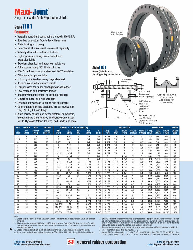
Photo of narrowarch joint shown.
Notes:1.) All parts listed are designed for 30" Hg (full vacuum) and have a maximum test at 26" Hg due to facility altitude and equipment
limitations.2.) Maximum operating temperature of 250 deg F for EPDM, Butyl, Hypalon, and Viton; 225 deg F for Neoprene; 210 deg F for Nitrile;
180 deg F for Pure Gum Rubber; 300 deg F for EPDM and Butyl in air service at 25 PSI maximum; higher pressure and tem-perature ratings available.
3.) All sizes can be supplied with a filled arch reducing their movements by 50% and increasing the spring rates fourfold.4.) For full product specifications and installation instructions, see SPEC 1101-1 and ININ 1101-1. Gross weights include retaining rings.
5.) WARNING: Control units (sold separately) must be used when piping is not properly anchored. Number of rods are dependentupon maximum field test pressures. Expansion joints may operate in pipelines carrying fluids at elevated temperatures and pres-sures, so precaution should be taken to ensure proper installation and regular inspection. Care is required to protect personnelin the event of leakage or splash. Adequate floor drains are always recommended.
6.) Movements are non-concurrent. Contact General Rubber for concurrent movements, and for sizes not shown up to 144" I.D.7.) Series 1100 and 1200 replace styles 1025, 1050 and 1075.8.) Standard 125/150 lb. drilling includes, 1"-24" with ANSI B16.1 Class 125 lb./B16.5 Class 150 lb., 30"-60" with ANSI B16.1 Class
125 lb./ B16.47 series A, Class 150 lb., 72"- 108" with ANSI B16.1 Class 125 lb./ AWWA C207 Class B.
Maxi-Joint®
Single (1) Wide Arch Expansion Joints
Style1101Features:• Versatile hand-built construction. Made in the U.S.A.• Standard or custom face to face dimensions• Wide flowing arch design• Exceptional all directional movement capability• Virtually eliminates sediment buildup• Higher pressure rating than conventional
expansion joints• Excellent chemical and abrasion resistance• Full vacuum rating (30" Hg) in all sizes• 250ºF continuous service standard, 400ºF available• Filled arch design available• Hot dip galvanized retaining rings standard• Absorbs noise, vibration and shock• Compensates for minor misalignment and offset• Low stiffness and deflection forces• Integrally flanged design, no gaskets required• Simple to install and high strength• Provides easy access to piping and equipment• Other standard drilling available, including ASA 300,
DIN, PN, JIS, API, and Navy• Wide variety of tube and cover elastomers available,
including Pure Gum Rubber, EPDM, Neoprene, Butyl,Nitrile, Hypalon®, Viton®, Teflon®, Food Grade, and more
Style1101Single (1) Wide Arch,Spool Type, Expansion Joints
general rubber corporationWeb: www.general-rubber.com [email protected] Free: 800-233-6294 Fax: 201-935-1915
6
7
general rubber corporationWeb: www.general-rubber.com [email protected] Free: 800-233-6294 Fax: 201-935-1915
Control Unit(See Note 5)
F/F
I.D.
O.D.
TH
Hot DippedGalvanizedRetainingRings
1/4" MinimumThicknessLeakproofElastomerTube
Embedded Steeland MultipleLayers of Tire CordReinforcement
Optional Filled ArchConstruction
Also Typical forOther Styles
2 10 220 15 6 4-3/4 4 3/4 7/8 3 1/2 1 3/4 2 78 8 135 170 225 122-1/2 10 220 15 7 5-1/2 4 3/4 7/8 3 1/2 1 3/4 2 66 7.6 170 210 240 14
3 10 220 15 7-1/2 6 4 3/4 7/8 3 1/2 1 3/4 2 56 7.4 200 255 270 174 10 220 15 9 7-1/2 8 3/4 7/8 3 1/2 1 3/4 2 44 7.2 275 355 295 215 10 220 15 10 8-1/2 8 7/8 7/8 3 1/2 1 3/4 2 36 6.8 335 440 355 246 10 220 15 11 9-1/2 8 7/8 7/8 3 1/2 1 3/4 2 30 6.4 410 525 395 298 10 220 15 13-1/2 11-3/4 8 7/8 7/8 3 1/2 1 3/4 2 24 6.2 495 580 480 42
10 12 220 15 16 14-1/4 12 1 7/8 4 2 2 1/2 34 6 480 585 410 5312 12 220 15 19 17 12 1 7/8 4 2 2 1/2 28 5.8 505 625 485 6914 12 220 15 21 18-3/4 12 1-1/8 1 4 1/2 2 1/4 2 1/2 24 5.6 540 650 570 9316 12 160 15 23-1/2 21-1/4 16 1-1/8 1 4 1/2 2 1/4 2 1/2 22 5.4 575 695 660 11018 12 160 15 25 22-3/4 16 1-1/4 1 4 1/2 2 1/4 2 1/2 20 5.2 610 785 725 11920 12 130 15 27-1/2 25 20 1-1/4 1 4 1/2 2 1/4 2 1/2 18 5 640 875 810 14324 15 130 15 32 29-1/2 20 1-3/8 1 1/8 5 2 1/2 2 3/4 16 4.8 865 1,050 870 16630 15 100 10 38-3/4 36 28 1-3/8 1 1/8 5 2 1/2 2 3/4 14 4.6 1,090 1,330 1,095 22536 15 90 10 46 42-3/4 32 1-5/8 1 1/8 5 2 1/2 2 3/4 12 4.4 1,330 1,625 1,340 30442 16 90 10 53 49-1/2 36 1-5/8 1 1/8 5 2 1/2 3 9.6 4.2 1,515 1,825 1,510 37848 16 90 10 59-1/2 56 44 1-5/8 1 1/8 5 2 1/2 3 8.4 4 1,695 2,075 1,705 44954 16 85 10 66-1/4 62-3/4 44 2 1 1/8 5 2 1/2 3 7.6 3.8 2,060 2,510 2,070 54760 16 85 10 73 69-1/4 52 2 1 1/8 5 2 1/2 3 7.2 3.6 2,260 2,780 2,290 64666 16 85 10 80 76 52 2 1 1/8 5 2 1/2 3 6.6 3.4 2,625 3,195 2,635 74972 16 85 10 86-1/2 82-1/2 60 2 1 1/4 5 2 1/2 3 6 3.2 2,950 3,590 2,960 82678 16 80 10 93 89 64 2-1/8 1 1/4 5 2 1/2 3 5.2 3 3,210 3,925 3,285 1,08884 16 80 10 99-3/4 95-1/2 64 2-1/4 1 1/4 5 2 1/2 3 4.6 2.8 3,475 4,335 3,700 1,33890 16 80 10 106-1/2 102 68 2-3/8 1 1/4 5 2 1/2 3 4.2 2.6 3,635 4,600 4,040 1,47496 16 80 10 113-1/4 108-1/2 68 2-1/2 1 1/4 5 2 1/2 3 4 2.4 3,825 5,050 4,535 1,583
102 16 60 10 120 114-1/2 72 2-5/8 1 3/8 5 2 1/2 3 3.2 1.6 4,064 5,365 4,820 1,682108 16 60 10 126-3/4 120-3/4 72 2-5/8 1 3/8 5 2 1/2 3 3 1.4 4,303 5,680 5,100 1,780
SIZE LENGTH MAX VACUUM FLANGES – 125/150 LB. (NOTE 8) MOVEMENTS SPRING RATE GROSSI.D. F/F Pressure Rating O.D. B.C. Hole Hole TH. Comp. Ext. Lateral Angular Torsional Comp. Ext. Lateral Weight
(inch) (inch) (PSIG) (inch Hg) (inch) (inch) (no.) (inch) (inch) (inch) (inch) (inch) (degree) (degree) (lbs/in) (lbs/in) (lbs/in) (lbs)
Notes:1.) Series 1200 are designed for 30” Hg (full vacuum) and have a maximum test at 26” Hg due to facility altitude and equipment
limitations.2.) Maximum operating temperature of 250 deg F for EPDM, Butyl, Hypalon, and Viton; 225 deg F for Neoprene; 210 deg F for Nitrile;
180 deg F for Pure Gum Rubber; 300 deg F for EPDM and Butyl in air service at 25 PSI maximum; higher pressure and tem-perature ratings available.
3.) All sizes can be supplied with a filled arch reducing their movements by 50% and increasing the spring rates fourfold.4.) For full product specifications and installation instructions, see SPEC 1102-1 and ININ 1102-1. Gross weights include retaining rings.
5.) WARNING: Control units (sold separately) must be used when piping is not properly anchored. Number of rods are dependentupon maximum field test pressures. Expansion joints may operate in pipelines carrying fluids at elevated temperatures and pres-sures, so precaution should be taken to ensure proper installation and regular inspection. Care is required to protect personnelin the event of leakage or splash. Adequate floor drains are always recommended.
6.) Movements are non-concurrent. Contact General Rubber for concurrent movements, and for sizes not shown up to 144” I.D.7.) Series 1100 and 1200 replace styles 1025, 1050 and 1075.8.) Standard 125/150 lb. drilling includes, 1”-24” with ANSI B16.1 Class 125 lb./B16.5 Class 150 lb., 30”-60” with ANSI B16.1 Class
125 lb./ B16.47 series A, Class 150 lb., 72”- 108” with ANSI B16.1 Class 125 lb./ AWWA C207 Class B.
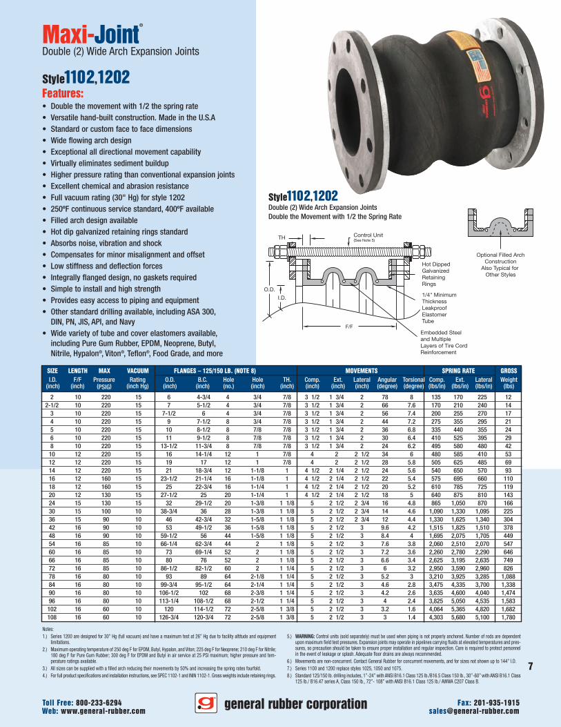
Maxi-Joint®
Double (2) Wide Arch Expansion Joints
Style1102,1202Features:• Double the movement with 1/2 the spring rate• Versatile hand-built construction. Made in the U.S.A• Standard or custom face to face dimensions• Wide flowing arch design• Exceptional all directional movement capability• Virtually eliminates sediment buildup• Higher pressure rating than conventional expansion joints• Excellent chemical and abrasion resistance• Full vacuum rating (30" Hg) for style 1202• 250ºF continuous service standard, 400ºF available• Filled arch design available• Hot dip galvanized retaining rings standard• Absorbs noise, vibration and shock• Compensates for minor misalignment and offset• Low stiffness and deflection forces• Integrally flanged design, no gaskets required• Simple to install and high strength• Provides easy access to piping and equipment• Other standard drilling available, including ASA 300,
DIN, PN, JIS, API, and Navy• Wide variety of tube and cover elastomers available,
including Pure Gum Rubber, EPDM, Neoprene, Butyl,Nitrile, Hypalon®, Viton®, Teflon®, Food Grade, and more
Style1102,1202Double (2) Wide Arch Expansion JointsDouble the Movement with 1/2 the Spring Rate
F/F
I.D.O.D.
TH
Hot DippedGalvanizedRetainingRings
1/4" MinimumThicknessLeakproofElastomer Tube
Embedded Steeland Multiple Layersof Tire CordReinforcement
Control Unit(See Note 5)
Optional Filled ArchConstruction
Also Typical forOther Styles
2 14 220 15 6 4-3/4 4 3/4 7/8 5 1/4 2 5/8 3 117 12 90 113 150 162-1/2 14 220 15 7 5-1/2 4 3/4 7/8 5 1/4 2 5/8 3 99 11.4 113 140 160 19
3 14 220 15 7-1/2 6 4 3/4 7/8 5 1/4 2 5/8 3 84 11.1 133 170 180 224 14 220 15 9 7-1/2 8 3/4 7/8 5 1/4 2 5/8 3 66 10.8 183 237 197 285 14 220 15 10 8-1/2 8 7/8 7/8 5 1/4 2 5/8 3 54 10.2 223 293 237 336 14 220 15 11 9-1/2 8 7/8 7/8 5 1/4 2 5/8 3 45 9.6 273 350 263 488 14 220 15 13-1/2 11-3/4 8 7/8 7/8 5 1/4 2 5/8 3 36 9.3 330 387 320 57
10 16 220 15 16 14-1/4 12 1 7/8 6 3 3 3/4 51 9 320 390 273 6912 16 220 15 19 17 12 1 7/8 6 3 3 3/4 42 8.7 337 417 323 9014 16 220 15 21 18-3/4 12 1-1/8 1 6 3/4 3 3/8 3 3/4 36 8.4 360 433 380 12216 16 160 15 23-1/2 21-1/4 16 1-1/8 1 6 3/4 3 3/8 3 3/4 33 8.1 383 463 440 14418 16 160 15 25 22-3/4 16 1-1/4 1 6 3/4 3 3/8 3 3/4 30 7.8 407 523 483 15720 16 130 15 27-1/2 25 20 1-1/4 1 6 3/4 3 3/8 3 3/4 27 7.5 427 583 540 18924 20 130 15 32 29-1/2 20 1-3/8 1 1/8 7 1/2 3 3/4 4 1/8 24 7.2 577 700 580 21130 20 100 10 38-3/4 36 28 1-3/8 1 1/8 7 1/2 3 3/4 4 1/8 21 6.9 727 887 730 28336 20 90 10 46 42-3/4 32 1-5/8 1 1/8 7 1/2 3 3/4 4 1/8 18 6.6 887 1083 893 38742 22 90 10 53 49-1/2 36 1-5/8 1 1/8 7 1/2 3 3/4 4 1/2 14.4 6.3 1010 1217 1007 46948 22 90 10 59-1/2 56 44 1-5/8 1 1/8 7 1/2 3 3/4 4 1/2 12.6 6 1130 1383 1137 55454 22 85 10 66-1/4 62-3/4 44 2 1 1/8 7 1/2 3 3/4 4 1/2 11.4 5.7 1373 1673 1380 68060 22 85 10 73 69-1/4 52 2 1 1/8 7 1/2 3 3/4 4 1/2 10.8 5.4 1507 1853 1527 80066 22 85 10 80 76 52 2 1 1/8 7 1/2 3 3/4 4 1/2 9.9 5.1 1750 2130 1757 92872 22 85 10 86-1/2 82-1/2 60 2 1 1/4 7 1/2 3 3/4 4 1/2 9 4.8 1967 2393 1973 1,01878 22 80 10 93 89 64 2-1/8 1 1/4 7 1/2 3 3/4 4 1/2 7.8 4.5 2140 2617 2190 1,36384 22 80 10 99-3/4 95-1/2 64 2-1/4 1 1/4 7 1/2 3 3/4 4 1/2 6.9 4.2 2317 2890 2467 1,68890 22 80 10 106-1/2 102 68 2-3/8 1 1/4 7 1/2 3 3/4 4 1/2 6.3 3.9 2423 3067 2693 1,84996 22 80 10 113-1/4 108-1/2 68 2-1/2 1 1/4 7 1/2 3 3/4 4 1/2 6 3.6 2550 3367 3023 1,983
102 22 60 10 120 114-1/2 72 2-5/8 1 3/8 7 1/2 3 3/4 4 1/2 4.8 2.4 2709 3577 3213 2,106108 22 60 10 126-3/4 120-3/4 72 2-5/8 1 3/8 7 1/2 3 3/4 4 1/2 4.5 2.1 2869 3787 3400 2,230
SIZE LENGTH MAX VACUUM FLANGES – 125/150 LB. (NOTE 8) MOVEMENTS SPRING RATE GROSSI.D. F/F Pressure Rating O.D. B.C. Hole Hole TH. Comp. Ext. Lateral Angular Torsional Comp. Ext. Lateral Weight
(inch) (inch) (PSIG) (inch Hg) (inch) (inch) (no.) (inch) (inch) (inch) (inch) (inch) (degree) (degree) (lbs/in) (lbs/in) (lbs/in) (lbs)
Notes:1.) Series 1200 are designed for 30” Hg (full vacuum) and have a maximum test at 26” Hg due to facility altitude and equipment
limitations.2.) Maximum operating temperature of 250 deg F for EPDM, Butyl, Hypalon, and Viton; 225 deg F for Neoprene; 210 deg F for Nitrile;
180 deg F for Pure Gum Rubber; 300 deg F for EPDM and Butyl in air service at 25 PSI maximum; higher pressure and tem-perature ratings available.
3.) All sizes can be supplied with a filled arch reducing their movements by 50% and increasing the spring rates fourfold.4.) For full product specifications and installation instructions, see SPEC 1103-1 and ININ 1103-1. Gross weights include retaining rings.
5.) WARNING: Control units (sold separately) must be used when piping is not properly anchored. Number of rods are dependentupon maximum field test pressures. Expansion joints may operate in pipelines carrying fluids at elevated temperatures and pres-sures, so precaution should be taken to ensure proper installation and regular inspection. Care is required to protect personnelin the event of leakage or splash. Adequate floor drains are always recommended.
6.) Movements are non-concurrent. Contact General Rubber for concurrent movements, and for sizes not shown up to 144” I.D.7.) Series 1100 and 1200 replace styles 1025, 1050 and 1075.8.) Standard 125/150 lb. drilling includes, 1”-24” with ANSI B16.1 Class 125 lb./B16.5 Class 150 lb., 30”-60” with ANSI B16.1 Class
125 lb./ B16.47 series A, Class 150 lb., 72”- 108” with ANSI B16.1 Class 125 lb./ AWWA C207 Class B.
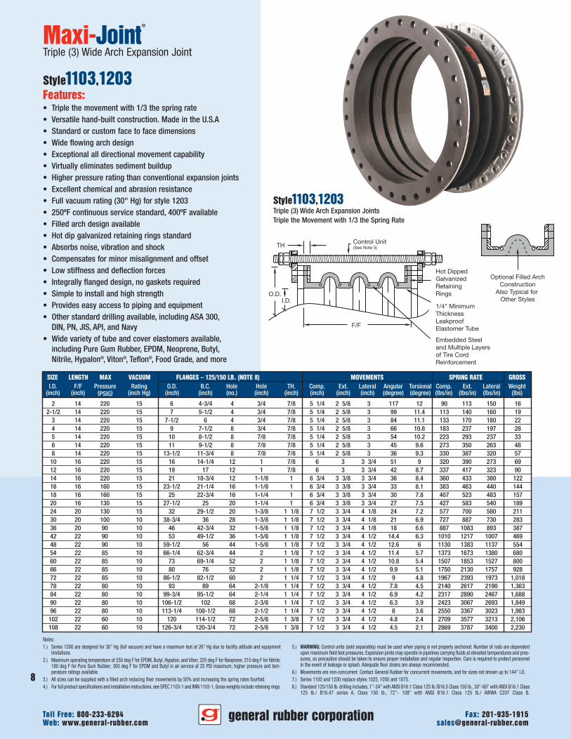
Maxi-Joint®
Triple (3) Wide Arch Expansion Joint
Style1103,1203Features:• Triple the movement with 1/3 the spring rate• Versatile hand-built construction. Made in the U.S.A• Standard or custom face to face dimensions• Wide flowing arch design• Exceptional all directional movement capability• Virtually eliminates sediment buildup• Higher pressure rating than conventional expansion joints• Excellent chemical and abrasion resistance• Full vacuum rating (30" Hg) for style 1203• 250ºF continuous service standard, 400ºF available• Filled arch design available• Hot dip galvanized retaining rings standard• Absorbs noise, vibration and shock• Compensates for minor misalignment and offset• Low stiffness and deflection forces• Integrally flanged design, no gaskets required• Simple to install and high strength• Provides easy access to piping and equipment• Other standard drilling available, including ASA 300,
DIN, PN, JIS, API, and Navy• Wide variety of tube and cover elastomers available,
including Pure Gum Rubber, EPDM, Neoprene, Butyl,Nitrile, Hypalon®, Viton®, Teflon®, Food Grade, and more
Style1103,1203Triple (3) Wide Arch Expansion JointsTriple the Movement with 1/3 the Spring Rate
general rubber corporationWeb: www.general-rubber.com [email protected] Free: 800-233-6294 Fax: 201-935-1915
8
9
general rubber corporationWeb: www.general-rubber.com [email protected] Free: 800-233-6294 Fax: 201-935-1915
F/F
I.D.O.D.
TH
Hot DippedGalvanizedRetainingRings
1/4" MinimumThicknessLeakproofElastomer Tube
Embedded Steeland Multiple Layersof Tire CordReinforcement
Control Unit(See Note 5)
Optional Filled ArchConstruction
Also Typical forOther Styles
2 18 220 15 6 4-3/4 4 3/4 7/8 7 3 1/2 4 156 16 68 85 113 202-1/2 18 220 15 7 5-1/2 4 3/4 7/8 7 3 1/2 4 132 15.2 85 105 120 23
3 18 220 15 7-1/2 6 4 3/4 7/8 7 3 1/2 4 112 14.8 100 128 135 274 18 220 15 9 7-1/2 8 3/4 7/8 7 3 1/2 4 88 14.4 138 178 148 355 18 220 15 10 8-1/2 8 7/8 7/8 7 3 1/2 4 72 13.6 168 220 178 416 18 220 15 11 9-1/2 8 7/8 7/8 7 3 1/2 4 60 12.8 205 263 198 488 18 220 15 13-1/2 11-3/4 8 7/8 7/8 7 3 1/2 4 48 12.4 248 290 240 72
10 20 220 15 16 14-1/4 12 1 7/8 8 4 5 68 12 240 293 205 8412 20 220 15 19 17 12 1 7/8 8 4 5 56 11.6 253 313 243 11114 20 220 15 21 18-3/4 12 1-1/8 1 9 4 1/2 5 48 11.2 270 325 285 15116 20 160 15 23-1/2 21-1/4 16 1-1/8 1 9 4 1/2 5 44 10.8 288 348 330 17818 20 160 15 25 22-3/4 16 1-1/4 1 9 4 1/2 5 40 10.4 305 393 363 19520 20 130 15 27-1/2 25 20 1-1/4 1 9 4 1/2 5 36 10 320 438 405 23424 24 130 15 32 29-1/2 20 1-3/8 1 1/8 10 5 5 1/2 32 9.6 433 525 435 25630 24 100 10 38-3/4 36 28 1-3/8 1 1/8 10 5 5 1/2 28 9.2 545 665 548 34736 24 90 10 46 42-3/4 32 1-5/8 1 1/8 10 5 5 1/2 24 8.8 665 813 670 46942 26 90 10 53 49-1/2 36 1-5/8 1 1/8 10 5 6 19.2 8.4 758 913 755 56048 26 90 10 59-1/2 56 44 1-5/8 1 1/8 10 5 6 16.8 8 848 1038 853 66054 26 85 10 66-1/4 62-3/4 44 2 1 1/8 10 5 6 15.2 7.6 1030 1255 1035 81260 26 85 10 73 69-1/4 52 2 1 1/8 10 5 6 14.4 7.2 1130 1390 1145 95566 26 85 10 80 76 52 2 1 1/8 10 5 6 13.2 6.8 1313 1598 1318 1,10872 26 85 10 86-1/2 82-1/2 60 2 1 1/4 10 5 6 12 6.4 1475 1795 1480 1,21178 26 80 10 93 89 64 2-1/8 1 1/4 10 5 6 10.4 6 1605 1963 1643 1,63884 26 80 10 99-3/4 95-1/2 64 2-1/4 1 1/4 10 5 6 9.2 5.6 1738 2168 1850 2,03890 26 80 10 106-1/2 102 68 2-3/8 1 1/4 10 5 6 8.4 5.2 1818 2300 2020 2,22496 26 80 10 113-1/4 108-1/2 68 2-1/2 1 1/4 10 5 6 8 4.8 1913 2525 2268 2,383
102 26 60 10 120 114-1/2 72 2-5/8 1 3/8 10 5 6 6.4 3.2 2032 2683 2410 2,532108 26 60 10 126-3/4 120-3/4 72 2-5/8 1 3/8 10 5 6 6 2.8 2152 2840 2550 2,681
SIZE LENGTH MAX VACUUM FLANGES – 125/150 LB. (NOTE 8) MOVEMENTS SPRING RATE GROSSI.D. F/F Pressure Rating O.D. B.C. Hole Hole TH. Comp. Ext. Lateral Angular Torsional Comp. Ext. Lateral Weight
(inch) (inch) (PSIG) (inch Hg) (inch) (inch) (no.) (inch) (inch) (inch) (inch) (inch) (degree) (degree) (lbs/in) (lbs/in) (lbs/in) (lbs)
Notes:1.) Series 1200 are designed for 30” Hg (full vacuum) and have a maximum test at 26” Hg due to facility altitude and equipment
limitations.2.) Maximum operating temperature of 250 deg F for EPDM, Butyl, Hypalon, and Viton; 225 deg F for Neoprene; 210 deg F for Nitrile;
180 deg F for Pure Gum Rubber; 300 deg F for EPDM and Butyl in air service at 25 PSI maximum; higher pressure and tem-perature ratings available.
3.) All sizes can be supplied with a filled arch reducing their movements by 50% and increasing the spring rates fourfold.4.) For full product specifications and installation instructions, see SPEC 1104-1 and ININ 1104-1. Gross weights include retaining rings.
5.) WARNING: Control units (sold separately) must be used when piping is not properly anchored. Number of rods are dependentupon maximum field test pressures. Expansion joints may operate in pipelines carrying fluids at elevated temperatures and pres-sures, so precaution should be taken to ensure proper installation and regular inspection. Care is required to protect personnelin the event of leakage or splash. Adequate floor drains are always recommended.
6.) Movements are non-concurrent. Contact General Rubber for concurrent movements, and for sizes not shown up to 144” I.D.7.) Series 1100 and 1200 replace styles 1025, 1050 and 1075.8.) Standard 125/150 lb. drilling includes, 1”-24” with ANSI B16.1 Class 125 lb./B16.5 Class 150 lb., 30”-60” with ANSI B16.1 Class
125 lb./ B16.47 series A, Class 150 lb., 72”- 108” with ANSI B16.1 Class 125 lb./ AWWA C207 Class B.
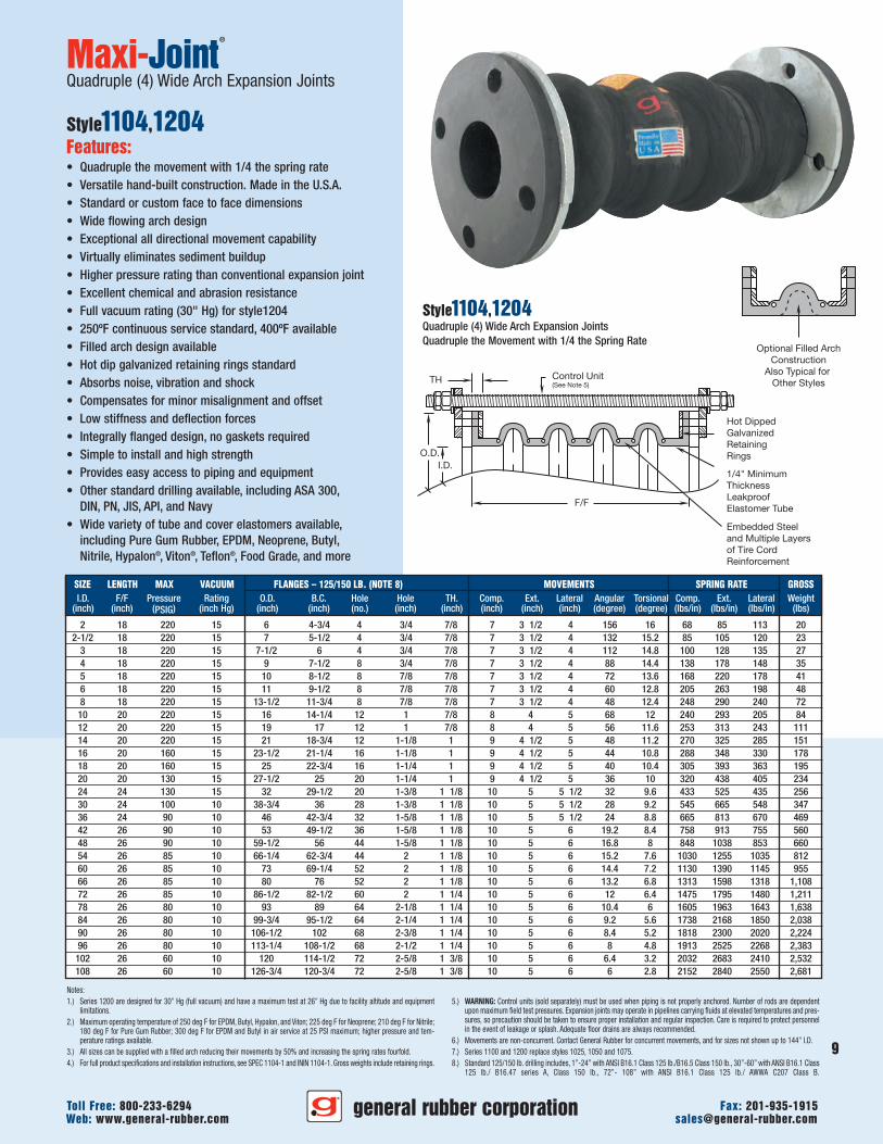
Maxi-Joint®
Quadruple (4) Wide Arch Expansion Joints
Style1104,1204Features:• Quadruple the movement with 1/4 the spring rate• Versatile hand-built construction. Made in the U.S.A.• Standard or custom face to face dimensions• Wide flowing arch design• Exceptional all directional movement capability• Virtually eliminates sediment buildup• Higher pressure rating than conventional expansion joint• Excellent chemical and abrasion resistance• Full vacuum rating (30" Hg) for style1204• 250ºF continuous service standard, 400ºF available• Filled arch design available• Hot dip galvanized retaining rings standard• Absorbs noise, vibration and shock• Compensates for minor misalignment and offset• Low stiffness and deflection forces• Integrally flanged design, no gaskets required• Simple to install and high strength• Provides easy access to piping and equipment• Other standard drilling available, including ASA 300,
DIN, PN, JIS, API, and Navy• Wide variety of tube and cover elastomers available,
including Pure Gum Rubber, EPDM, Neoprene, Butyl,Nitrile, Hypalon®, Viton®, Teflon®, Food Grade, and more
Style1104,1204Quadruple (4) Wide Arch Expansion JointsQuadruple the Movement with 1/4 the Spring Rate
F/F
TH
Embedded Steeland Multiple Layersof Tire CordReinforcement
Hot Dipped GalvanizedRetaining Rings
1/4"MinimumThicknessLeakproofElastomerTube
LargeEnd
SmallEnd
Notes:1.) All Series 1200 parts listed are designed for 30" Hg (full vacuum) and have a maximum test at 26" Hg due to facility altitude
and equipment limitations.2.) Maximum operating temperature of 250 deg F for EPDM, Butyl, Hypalon, and Viton; 225 deg F for Neoprene; 210 deg F for Nitrile;
180 deg F for Pure Gum Rubber; 300 deg F for EPDM and Butyl in air service at 25 PSI maximum; higher pressure and tem-perature ratings available.
3.) All sizes can be supplied with a filled arch reducing their movements by 50% and increasing the spring rates fourfold.4.) For full product specifications and installation instructions, see SPEC 1101CR-1 and ININ 1101CR-1. Gross weights include
retaining rings.
5.) WARNING: Control units (sold separately) must be used when piping is not properly anchored. Number of rods are dependentupon maximum field test pressures. Expansion joints may operate in pipelines carrying fluids at elevated temperatures and pres-sures, so precaution should be taken to ensure proper installation and regular inspection. Care is required to protect personnelin the event of leakage or splash. Adequate floor drains are always recommended.
6.) Movements are non-concurrent. Contact General Rubber for concurrent movements, and for sizes not shown up to 144" I.D.7.) Standard 125/150 lb. drilling includes, 1"-24" with ANSI B16.1 Class 125 lb./B16.5 Class 150 lb., 30"-60" with ANSI B16.1 Class
125 lb./ B16.47 series A, Class 150 lb., 72"- 108" with ANSI B16.1 Class 125 lb./ AWWA C207 Class B.
Maxi-Joint®
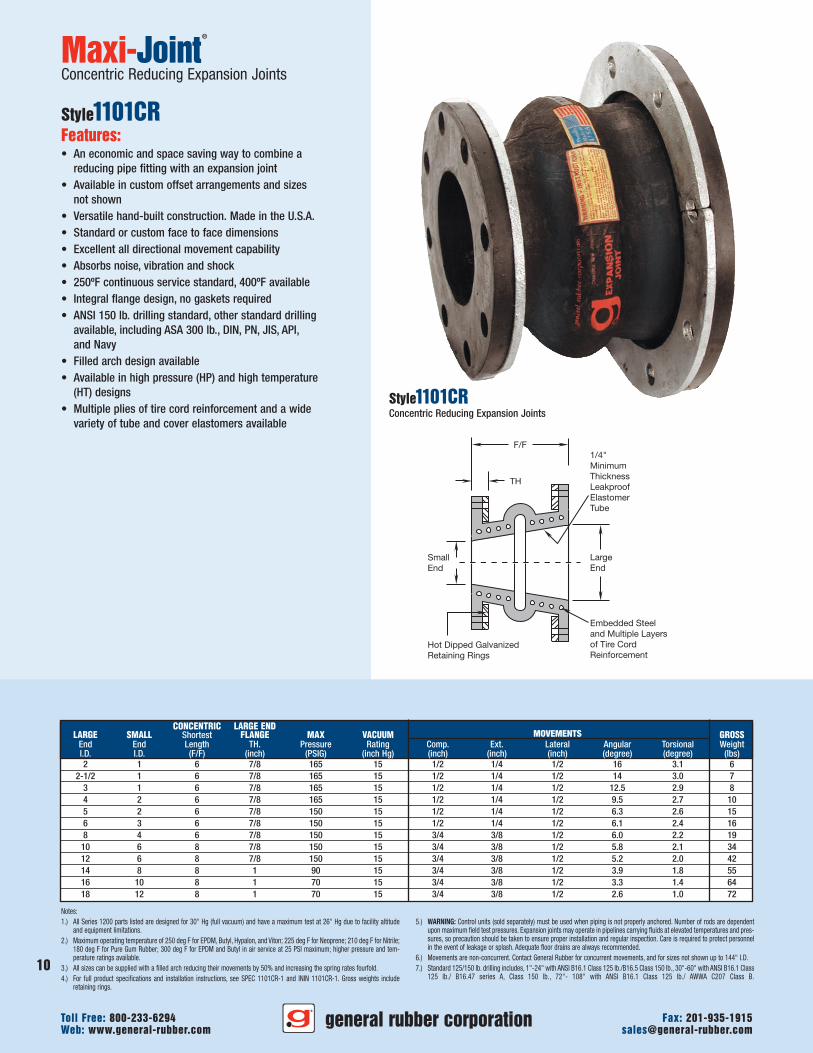
Concentric Reducing Expansion Joints
Style1101CRFeatures:• An economic and space saving way to combine a
reducing pipe fitting with an expansion joint• Available in custom offset arrangements and sizes
not shown• Versatile hand-built construction. Made in the U.S.A.• Standard or custom face to face dimensions• Excellent all directional movement capability• Absorbs noise, vibration and shock• 250ºF continuous service standard, 400ºF available• Integral flange design, no gaskets required• ANSI 150 lb. drilling standard, other standard drilling
available, including ASA 300 lb., DIN, PN, JIS, API,and Navy
• Filled arch design available• Available in high pressure (HP) and high temperature
(HT) designs• Multiple plies of tire cord reinforcement and a wide
variety of tube and cover elastomers available
CONCENTRIC LARGE ENDLARGE SMALL Shortest FLANGE MAX VACUUM MOVEMENTS GROSS
End End Length TH. Pressure Rating Comp. Ext. Lateral Angular Torsional WeightI.D. I.D. (F/F) (inch) (PSIG) (inch Hg) (inch) (inch) (inch) (degree) (degree) (lbs)2 1 6 7/8 165 15 1/2 1/4 1/2 16 3.1 6
2-1/2 1 6 7/8 165 15 1/2 1/4 1/2 14 3.0 73 1 6 7/8 165 15 1/2 1/4 1/2 12.5 2.9 84 2 6 7/8 165 15 1/2 1/4 1/2 9.5 2.7 105 2 6 7/8 150 15 1/2 1/4 1/2 6.3 2.6 156 3 6 7/8 150 15 1/2 1/4 1/2 6.1 2.4 168 4 6 7/8 150 15 3/4 3/8 1/2 6.0 2.2 19
10 6 8 7/8 150 15 3/4 3/8 1/2 5.8 2.1 3412 6 8 7/8 150 15 3/4 3/8 1/2 5.2 2.0 4214 8 8 1 90 15 3/4 3/8 1/2 3.9 1.8 5516 10 8 1 70 15 3/4 3/8 1/2 3.3 1.4 6418 12 8 1 70 15 3/4 3/8 1/2 2.6 1.0 72
Style1101CRConcentric Reducing Expansion Joints
general rubber corporationWeb: www.general-rubber.com [email protected] Free: 800-233-6294 Fax: 201-935-1915
10
11
general rubber corporationWeb: www.general-rubber.com [email protected] Free: 800-233-6294 Fax: 201-935-1915
F/F
TH
LargeEndSmall
End
Embedded Steeland Multiple Layersof Tire CordReinforcementHot Dipped Galvanized
Retaining Rings
1/4"MinimumThicknessLeakproofElastomerTube
ECCENTRIC LARGE ENDLARGE SMALL Shortest FLANGE MAX VACUUM MOVEMENTS GROSS
End End Length TH. Pressure Rating Comp. Ext. Lateral Angular Torsional WeightI.D. I.D. (F/F) (inch) (PSIG) (inch Hg) (inch) (inch) (inch) (degree) (degree) (lbs)2 1 6 7/8 165 15 1/2 1/4 1/2 16 3.1 6
2-1/2 1 6 7/8 165 15 1/2 1/4 1/2 14 3.0 73 1 6 7/8 165 15 1/2 1/4 1/2 12.5 2.9 84 2 6 7/8 165 15 1/2 1/4 1/2 9.5 2.7 105 2 8 7/8 150 15 1/2 1/4 1/2 6.3 2.6 156 3 8 7/8 150 15 1/2 1/4 1/2 6.1 2.4 168 4 8 7/8 150 15 3/4 3/8 1/2 6.0 2.2 19
10 6 8 7/8 150 15 3/4 3/8 1/2 5.8 2.1 3412 6 10 7/8 150 15 3/4 3/8 1/2 5.2 2.0 4214 8 10 1 90 15 3/4 3/8 1/2 3.9 1.8 5516 10 10 1 70 15 3/4 3/8 1/2 3.3 1.4 6418 12 10 1 70 15 3/4 3/8 1/2 2.6 1.0 72
Notes:1.) All Series 1200 parts listed are designed for 30" Hg (full vacuum) and have a maximum test at 26" Hg due to facility altitude
and equipment limitations.2.) Maximum operating temperature of 250 deg F for EPDM, Butyl, Hypalon, and Viton; 225 deg F for Neoprene; 210 deg F for Nitrile;
180 deg F for Pure Gum Rubber; 300 deg F for EPDM and Butyl in air service at 25 PSI maximum; higher pressure and tem-perature ratings available.
3.) All sizes can be supplied with a filled arch reducing their movements by 50% and increasing the spring rates fourfold.4.) For full product specifications and installation instructions, see SPEC 1101CR-1 and ININ 1101CR-1. Gross weights include
retaining rings.
5.) WARNING: Control units (sold separately) must be used when piping is not properly anchored. Number of rods are dependentupon maximum field test pressures. Expansion joints may operate in pipelines carrying fluids at elevated temperatures and pres-sures, so precaution should be taken to ensure proper installation and regular inspection. Care is required to protect personnelin the event of leakage or splash. Adequate floor drains are always recommended.
6.) Movements are non-concurrent. Contact General Rubber for concurrent movements, and for sizes not shown up to 144" I.D.7.) Standard 125/150 lb. drilling includes, 1"-24" with ANSI B16.1 Class 125 lb./B16.5 Class 150 lb., 30"-60" with ANSI B16.1 Class
125 lb./ B16.47 series A, Class 150 lb., 72"- 108" with ANSI B16.1 Class 125 lb./ AWWA C207 Class B.
Maxi-Joint®
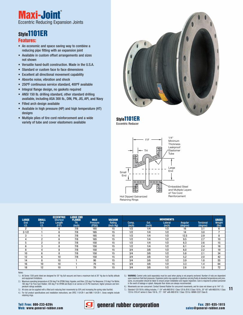
Eccentric Reducing Expansion Joints
Style1101ERFeatures:• An economic and space saving way to combine a
reducing pipe fitting with an expansion joint• Available in custom offset arrangements and sizes
not shown• Versatile hand-built construction. Made in the U.S.A.• Standard or custom face to face dimensions• Excellent all directional movement capability• Absorbs noise, vibration and shock• 250ºF continuous service standard, 400ºF available• Integral flange design, no gaskets required• ANSI 150 lb. drilling standard, other standard drilling
available, including ASA 300 lb., DIN, PN, JIS, API, and Navy• Filled arch design available• Available in high pressure (HP) and high temperature (HT)
designs• Multiple plies of tire cord reinforcement and a wide
variety of tube and cover elastomers availableStyle1101EREccentric Reducer
12
F/F
I.D.
O.D.
TH
Hot DippedGalvanizedRetaining Rings
LeakproofElastomer Tube
Multiple Layersof Tire CordReinforcement
Maxi-Joint®
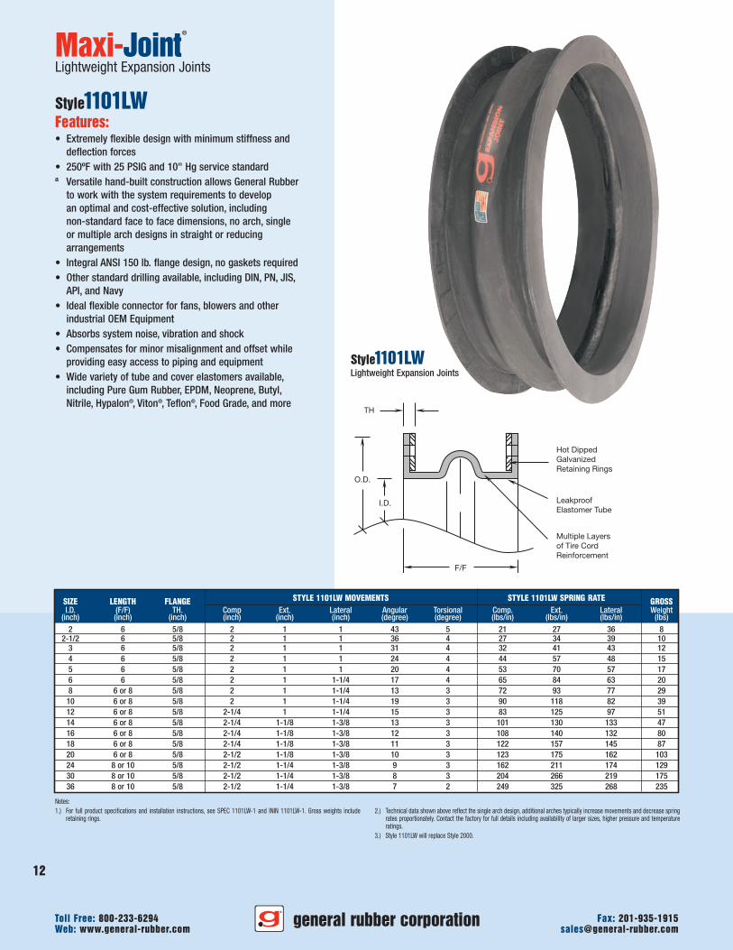
Lightweight Expansion Joints
Style1101LWFeatures:• Extremely flexible design with minimum stiffness and
deflection forces• 250ºF with 25 PSIG and 10" Hg service standardª Versatile hand-built construction allows General Rubber
to work with the system requirements to developan optimal and cost-effective solution, includingnon-standard face to face dimensions, no arch, singleor multiple arch designs in straight or reducingarrangements
• Integral ANSI 150 lb. flange design, no gaskets required• Other standard drilling available, including DIN, PN, JIS,
API, and Navy• Ideal flexible connector for fans, blowers and other
industrial OEM Equipment• Absorbs system noise, vibration and shock• Compensates for minor misalignment and offset while
providing easy access to piping and equipment• Wide variety of tube and cover elastomers available,
including Pure Gum Rubber, EPDM, Neoprene, Butyl,Nitrile, Hypalon®, Viton®, Teflon®, Food Grade, and more
Style1101LWLightweight Expansion Joints
SIZE LENGTH FLANGE STYLE 1101LW MOVEMENTS STYLE 1101LW SPRING RATE GROSSI.D. (F/F) TH. Comp Ext. Lateral Angular Torsional Comp. Ext. Lateral Weight
(inch) (inch) (inch) (inch) (inch) (inch) (degree) (degree) (lbs/in) (lbs/in) (lbs/in) (lbs)2 6 5/8 2 1 1 43 5 21 27 36 8
2-1/2 6 5/8 2 1 1 36 4 27 34 39 103 6 5/8 2 1 1 31 4 32 41 43 124 6 5/8 2 1 1 24 4 44 57 48 155 6 5/8 2 1 1 20 4 53 70 57 176 6 5/8 2 1 1-1/4 17 4 65 84 63 208 6 or 8 5/8 2 1 1-1/4 13 3 72 93 77 29
10 6 or 8 5/8 2 1 1-1/4 19 3 90 118 82 3912 6 or 8 5/8 2-1/4 1 1-1/4 15 3 83 125 97 5114 6 or 8 5/8 2-1/4 1-1/8 1-3/8 13 3 101 130 133 4716 6 or 8 5/8 2-1/4 1-1/8 1-3/8 12 3 108 140 132 8018 6 or 8 5/8 2-1/4 1-1/8 1-3/8 11 3 122 157 145 8720 6 or 8 5/8 2-1/2 1-1/8 1-3/8 10 3 123 175 162 10324 8 or 10 5/8 2-1/2 1-1/4 1-3/8 9 3 162 211 174 12930 8 or 10 5/8 2-1/2 1-1/4 1-3/8 8 3 204 266 219 17536 8 or 10 5/8 2-1/2 1-1/4 1-3/8 7 2 249 325 268 235
Notes:1.) For full product specifications and installation instructions, see SPEC 1101LW-1 and ININ 1101LW-1. Gross weights include
retaining rings.2.) Technical data shown above reflect the single arch design, additional arches typically increase movements and decrease spring
rates proportionately. Contact the factory for full details including availability of larger sizes, higher pressure and temperatureratings.
3.) Style 1101LW will replace Style 2000.
general rubber corporationWeb: www.general-rubber.com [email protected] Free: 800-233-6294 Fax: 201-935-1915
F/F
I.D.
O.D.
TH
Hot DippedGalvanizedRetaining Rings
1/4" MinimumThicknessLeakproofElastomerTube
Embedded Steeland MultipleLayers of Tire CordReinforcement
Control Unit(See Note 5)
Notes:1.) All parts listed are designed for 30" Hg (full vacuum) and have a maximum test at 26" Hg due to facility altitude and equipment
limitations.2.) Maximum operating temperature of 250 deg F for EPDM, Butyl, Hypalon, and Viton; 225 deg F for Neoprene; 210 deg F for Nitrile;
180 deg F for Pure Gum Rubber; 300 deg F for EPDM and Butyl in air service at 25 PSI maximum; higher pressure and tem-perature ratings available.
3.) All sizes can be supplied with a filled arch reducing their movements by 50% and increasing the spring rates fourfold.4.) For full product specifications and installation instructions, see SPEC 1101HP-1 and ININ 1101HP-1. Gross weights include
retaining rings.5.) WARNING: Control units (sold separately) must be used when piping is not properly anchored. Number of rods are dependent
upon maximum field test pressures. Expansion joints may operate in pipelines carrying fluids at elevated temperatures and pres-sures, so precaution should be taken to ensure proper installation and regular inspection. Care is required to protect personnelin the event of leakage or splash. Adequate floor drains are always recommended.
6.) Movements are non-concurrent. Contact General Rubber for concurrent movements, and for sizes not shown up to 144" I.D.7.) All sizes can be supplied with multiple arches for increased movements and decreased spring rates.8.) Standard 125/150 lb. drilling includes, 1"-24" with ANSI B16.1 Class 125 lb./B16.5 Class 150 lb., 30"-60" with ANSI B16.1 Class
125 lb./ B16.47 series A, Class 150 lb., 72"- 108" with ANSI B16.1 Class 125 lb./ AWWA C207 Class B.9.) Contact General Rubber with your design conditions and we will provide a detailed drawing with our proposal.
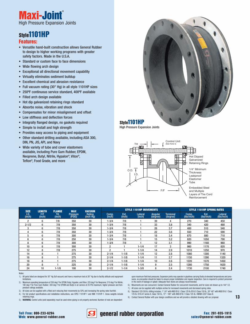
Maxi-Joint®
High Pressure Expansion Joints
Style1101HPFeatures:• Versatile hand-built construction allows General Rubber
to design to higher working programs with greatersafety factors. Made in the U.S.A.
• Standard or custom face to face dimensions• Wide flowing arch design• Exceptional all directional movement capability• Virtually eliminates sediment buildup• Excellent chemical and abrasion resistance• Full vacuum rating (30" Hg) in all style 1101HP sizes• 250ºF continuous service standard, 400ºF available• Filled arch design available• Hot dip galvanized retaining rings standard• Absorbs noise, vibration and shock• Compensates for minor misalignment and offset• Low stiffness and deflection forces• Integrally flanged design, no gaskets required• Simple to install and high strength• Provides easy access to piping and equipment• Other standard drilling available, including ASA 300,
DIN, PN, JIS, API, and Navy• Wide variety of tube and cover elastomers
available, including Pure Gum Rubber, EPDM,Neoprene, Butyl, Nitrile, Hypalon®, Viton®,Teflon®, Food Grade, and more
Style1101HPHigh Pressure Expansion Joints
general rubber corporationWeb: www.general-rubber.com [email protected] Free: 800-233-6294 Fax: 201-935-1915
13
SIZE LENGTH FLANGE MAX VACUUM STYLE 1101HP MOVEMENTS STYLE 1101HP SPRING RATES
I.D. F/F TH. Pressure Rating Comp. Ext. Lateral Angular Torsional Comp. Ext. Lateral(inch) (inch) (inch) (PSIG) (inch Hg) (inch) (inch) (inch) (degree) (degree) (lbs/inch) (lbs/inch) (lbs/inch)
2 6 7/8 350 30 1-3/4 7/8 1 39 4 270 340 4502-1/2 6 7/8 350 30 1-3/4 7/8 1 33 3.8 340 420 480
3 6 7/8 350 30 1-3/4 7/8 1 28 3.7 400 510 5404 6 7/8 350 30 1-3/4 7/8 1 22 3.6 550 710 5905 6 7/8 300 30 1-3/4 7/8 1 18 3.4 670 880 7106 6 7/8 250 30 1-3/4 7/8 1 15 3.2 820 1050 7908 6 7/8 300 30 1-3/4 7/8 1 12 3.1 990 1160 960
10 8 7/8 300 30 2 1 1-1/4 17 3 960 1170 82012 8 7/8 275 30 2 1 1-1/4 14 2.9 1010 1250 97014 8 1 275 30 2-1/4 1-1/8 1-1/4 12 2.8 1080 1300 114016 8 1 275 30 2-1/4 1-1/8 1-1/4 11 2.7 1150 1390 132018 8 1 275 30 2-1/4 1-1/8 1-1/4 10 2.6 1220 1570 145020 8 1 225 30 2-1/4 1-1/8 1-1/4 9 2.5 1280 1750 162024 10 1-1/8 190 30 2-1/2 1-1/4 1-3/8 8 2.4 1730 2100 1740
F/F
I.D.
O.D.
TH
Hot DippedGalvanizedRetaining Rings
1/4" MinimumThicknessLeakproofElastomerTube
Embedded Steeland MultipleLayers of Tire CordReinforcement
Control Unit(See Note 5)
Optional Filled ArchConstruction
Also Typical forOther Styles
Photo of narrow arch joint shown.
Maxi-Joint®
High Temperature Expansion Joints
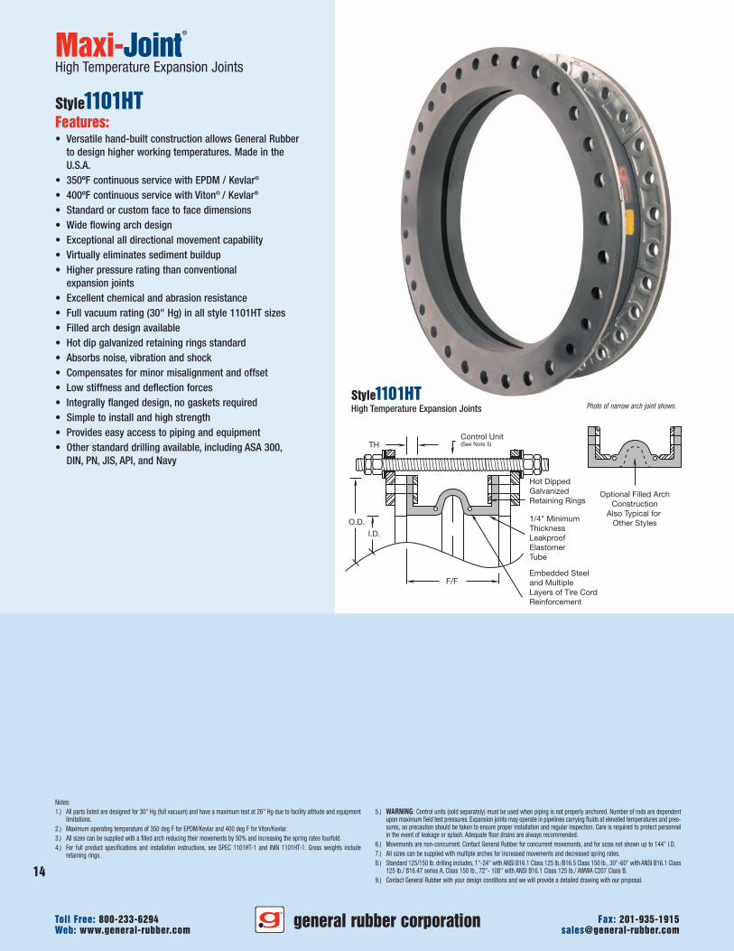
Style1101HTFeatures:• Versatile hand-built construction allows General Rubber
to design higher working temperatures. Made in theU.S.A.
• 350ºF continuous service with EPDM / Kevlar®
• 400ºF continuous service with Viton® / Kevlar®
• Standard or custom face to face dimensions• Wide flowing arch design• Exceptional all directional movement capability• Virtually eliminates sediment buildup• Higher pressure rating than conventional
expansion joints• Excellent chemical and abrasion resistance• Full vacuum rating (30" Hg) in all style 1101HT sizes• Filled arch design available• Hot dip galvanized retaining rings standard• Absorbs noise, vibration and shock• Compensates for minor misalignment and offset• Low stiffness and deflection forces• Integrally flanged design, no gaskets required• Simple to install and high strength• Provides easy access to piping and equipment• Other standard drilling available, including ASA 300,
DIN, PN, JIS, API, and Navy
Style1101HTHigh Temperature Expansion Joints
Notes:1.) All parts listed are designed for 30" Hg (full vacuum) and have a maximum test at 26" Hg due to facility altitude and equipment
limitations.2.) Maximum operating temperature of 350 deg F for EPDM/Kevlar and 400 deg F for Viton/Kevlar.3.) All sizes can be supplied with a filled arch reducing their movements by 50% and increasing the spring rates fourfold.4.) For full product specifications and installation instructions, see SPEC 1101HT-1 and ININ 1101HT-1. Gross weights include
retaining rings.
5.) WARNING: Control units (sold separately) must be used when piping is not properly anchored. Number of rods are dependentupon maximum field test pressures. Expansion joints may operate in pipelines carrying fluids at elevated temperatures and pres-sures, so precaution should be taken to ensure proper installation and regular inspection. Care is required to protect personnelin the event of leakage or splash. Adequate floor drains are always recommended.
6.) Movements are non-concurrent. Contact General Rubber for concurrent movements, and for sizes not shown up to 144" I.D.7.) All sizes can be supplied with multiple arches for increased movements and decreased spring rates.8.) Standard 125/150 lb. drilling includes, 1"-24" with ANSI B16.1 Class 125 lb./B16.5 Class 150 lb., 30"-60" with ANSI B16.1 Class
125 lb./ B16.47 series A, Class 150 lb., 72"- 108" with ANSI B16.1 Class 125 lb./ AWWA C207 Class B.9.) Contact General Rubber with your design conditions and we will provide a detailed drawing with our proposal.
general rubber corporationWeb: www.general-rubber.com [email protected] Free: 800-233-6294 Fax: 201-935-1915
14
15
general rubber corporationWeb: www.general-rubber.com [email protected] Free: 800-233-6294 Fax: 201-935-1915
Notes:1.) All parts listed are designed for 30" Hg (full vacuum) and have a maximum test at 26" Hg due to facility altitude and equipment
limitations.2.) Maximum operating temperature of 350 deg F for EPDM/Kevlar and 400 deg F for Viton/Kevlar.3.) All sizes can be supplied with a filled arch reducing their movements by 50% and increasing the spring rates fourfold.4.) For full product specifications and installation instructions, see SPEC 1101HT-1 and ININ 1101HT-1. Gross weights include
retaining rings.
5.) WARNING: Control units (sold separately) must be used when piping is not properly anchored. Number of rods are dependentupon maximum field test pressures. Expansion joints may operate in pipelines carrying fluids at elevated temperatures and pres-sures, so precaution should be taken to ensure proper installation and regular inspection. Care is required to protect personnelin the event of leakage or splash. Adequate floor drains are always recommended.
6.) Movements are non-concurrent. Contact General Rubber for concurrent movements, and for sizes not shown up to 144" I.D.7.) All sizes can be supplied with multiple arches for increased movements and decreased spring rates.8.) Standard 125/150 lb. drilling includes, 1"-24" with ANSI B16.1 Class 125 lb./B16.5 Class 150 lb., 30"-60" with ANSI B16.1 Class
125 lb./ B16.47 series A, Class 150 lb., 72"- 108" with ANSI B16.1 Class 125 lb./ AWWA C207 Class B.9.) Contact General Rubber with your design conditions and we will provide a detailed drawing with our proposal.
Maxi-Joint®
Dismantling Expansion Joints
Style1101DJFeatures:• Versatile hand-built construction allows General Rubber
to design self retracting designs with integral gussetedrotating rings embedded. Made in the U.S.A.
• Standard or custom face to face dimensions• Wide flowing arch design• Exceptional all directional movement capability• Virtually eliminates sediment buildup• Higher pressure rating than conventional
expansion joints• Excellent chemical and abrasion resistance• Full vacuum rating (30" Hg) in all style 1101 sizes• 250ºF continuous service standard, 400ºF available• Filled arch design available• Hot dip galvanized retaining rings standard• Absorbs noise, vibration and shock• Compensates for minor misalignment and offset• Low stiffness and deflection forces• Integrally flanged design, no gaskets required• Simple to install and high strength• Provides easy access to piping and equipment• Other standard drilling available, including ASA 300,
DIN, PN, JIS, API, and Navy• Wide variety of tube and cover elastomers available,
including Pure Gum Rubber, EPDM, Neoprene, Butyl,Nitrile, Hypalon®, Viton®, Teflon®, Food Grade, and more
Style1101DJDismantling Joint with Turnbuckles
Section A-A
A
A
Steel and Multiple Layersof Tire Cord Reinforcement
Hot Dipped GalvanizedRetaining Rings
I.D.
TH
F/F
LeakproofElastomerTube
Notes:1.) All Series 1200 parts listed are designed for 30" Hg (full vacuum) and have a maximum test at 26" Hg due to facility altitude
and equipment limitations.2.) Maximum operating temperature of 250 deg F for EPDM, Butyl, Hypalon, and Viton; 225 deg F for Neoprene; 210 deg F for Nitrile;
180 deg F for Pure Gum Rubber; 300 deg F for EPDM and Butyl in air service at 25 PSI maximum; higher pressure and tem-perature ratings available.
3.) For full product specifications and installation instructions, see SPEC 1100-1 and ININ 1100-1. Gross weights include retainingrings.
4.) WARNING: Control units (sold separately) must be used when piping is not properly anchored. Number of rods are dependentupon maximum field test pressures. Expansion joints may operate in pipelines carrying fluids at elevated temperatures and pres-sures, so precaution should be taken to ensure proper installation and regular inspection. Care is required to protect personnelin the event of leakage or splash. Adequate floor drains are always recommended.
5.) Movements are non-concurrent. Contact General Rubber for concurrent movements, and for sizes not shown up to 144" I.D.6.) Standard 125/150 lb. drilling includes, 1"-24" with ANSI B16.1 Class 125 lb./B16.5 Class 150 lb., 30"-60" with ANSI B16.1 Class
125 lb./ B16.47 series A, Class 150 lb., 72"- 108" with ANSI B16.1 Class 125 lb./ AWWA C207 Class B.
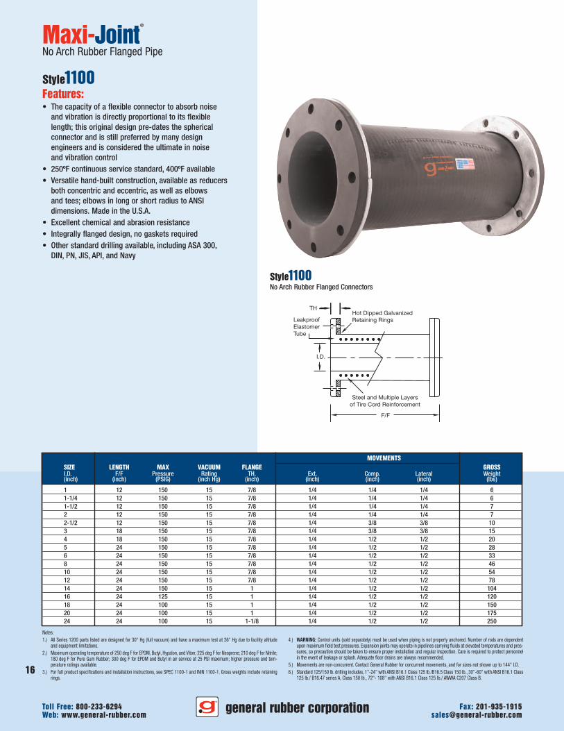
Maxi-Joint®
No Arch Rubber Flanged Pipe
Style1100Features:• The capacity of a flexible connector to absorb noise
and vibration is directly proportional to its flexiblelength; this original design pre-dates the sphericalconnector and is still preferred by many designengineers and is considered the ultimate in noiseand vibration control
• 250ºF continuous service standard, 400ºF available• Versatile hand-built construction, available as reducers
both concentric and eccentric, as well as elbowsand tees; elbows in long or short radius to ANSIdimensions. Made in the U.S.A.
• Excellent chemical and abrasion resistance• Integrally flanged design, no gaskets required• Other standard drilling available, including ASA 300,
DIN, PN, JIS, API, and Navy
Style1100No Arch Rubber Flanged Connectors
MOVEMENTSSIZE LENGTH MAX VACUUM FLANGE GROSSI.D. F/F Pressure Rating TH. Ext. Comp. Lateral Weight(inch) (inch) (PSIG) (inch Hg) (inch) (inch) (inch) (inch) (lbs)
1 12 150 15 7/8 1/4 1/4 1/4 61-1/4 12 150 15 7/8 1/4 1/4 1/4 61-1/2 12 150 15 7/8 1/4 1/4 1/4 72 12 150 15 7/8 1/4 1/4 1/4 72-1/2 12 150 15 7/8 1/4 3/8 3/8 103 18 150 15 7/8 1/4 3/8 3/8 154 18 150 15 7/8 1/4 1/2 1/2 205 24 150 15 7/8 1/4 1/2 1/2 286 24 150 15 7/8 1/4 1/2 1/2 338 24 150 15 7/8 1/4 1/2 1/2 4610 24 150 15 7/8 1/4 1/2 1/2 5412 24 150 15 7/8 1/4 1/2 1/2 7814 24 150 15 1 1/4 1/2 1/2 10416 24 125 15 1 1/4 1/2 1/2 12018 24 100 15 1 1/4 1/2 1/2 15020 24 100 15 1 1/4 1/2 1/2 17524 24 100 15 1-1/8 1/4 1/2 1/2 250
general rubber corporationWeb: www.general-rubber.com [email protected] Free: 800-233-6294 Fax: 201-935-1915
16
17
general rubber corporationWeb: www.general-rubber.com [email protected] Free: 800-233-6294 Fax: 201-935-1915
I.D.
TH
C
C
I.D.
THC
C
C
I.D.
TH
C
Notes:1.) Contact General Rubber with your design conditions and we will provide a detailed drawing with our proposal.
Pressures are not normally as high as our straight Style 1100.
Maxi-Joint®
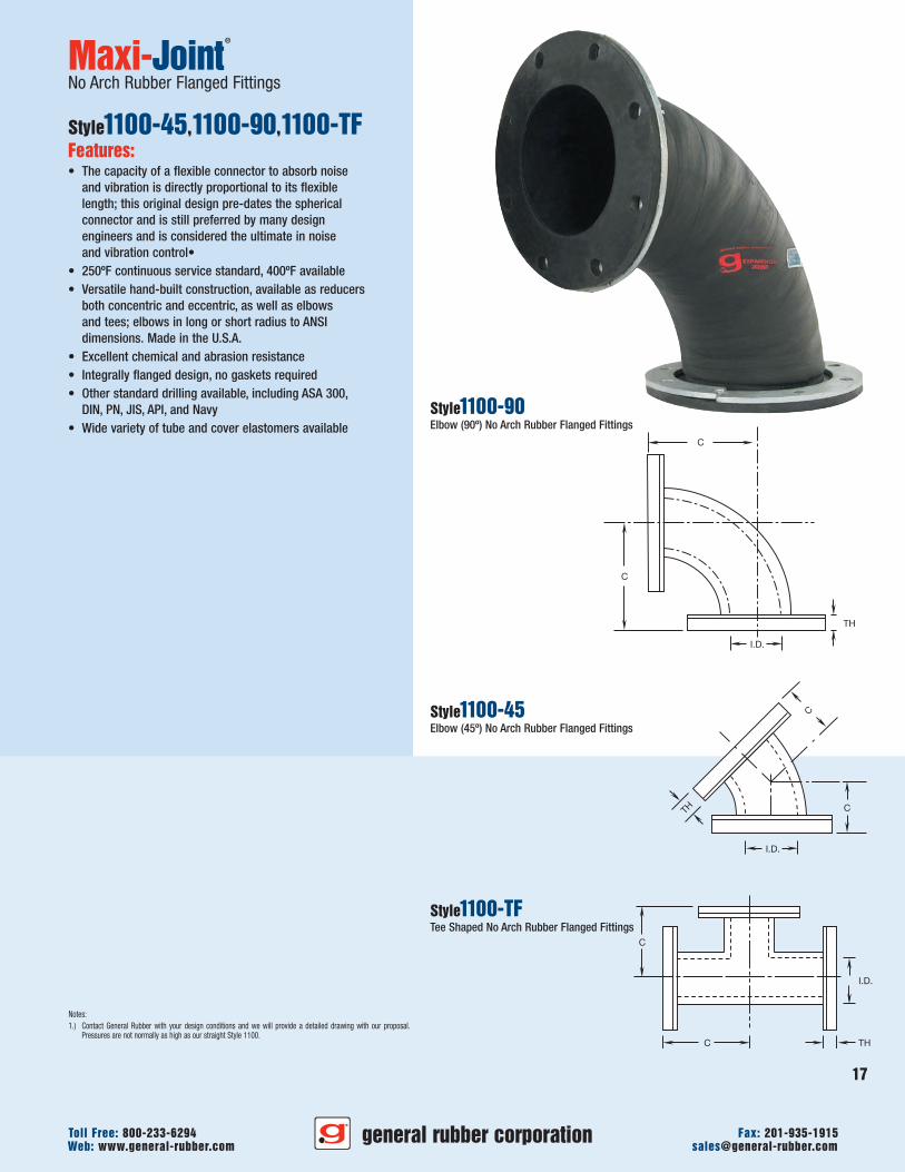
No Arch Rubber Flanged Fittings
Style1100-45,1100-90,1100-TFFeatures:• The capacity of a flexible connector to absorb noise
and vibration is directly proportional to its flexiblelength; this original design pre-dates the sphericalconnector and is still preferred by many designengineers and is considered the ultimate in noiseand vibration control•
• 250ºF continuous service standard, 400ºF available• Versatile hand-built construction, available as reducers
both concentric and eccentric, as well as elbowsand tees; elbows in long or short radius to ANSIdimensions. Made in the U.S.A.
• Excellent chemical and abrasion resistance• Integrally flanged design, no gaskets required• Other standard drilling available, including ASA 300,
DIN, PN, JIS, API, and Navy• Wide variety of tube and cover elastomers available
Style1100-90Elbow (90º) No Arch Rubber Flanged Fittings
Style1100-45Elbow (45º) No Arch Rubber Flanged Fittings
Style1100-TFTee Shaped No Arch Rubber Flanged Fittings
F/F
I.D.
O.D.
TH Control Unit(See Note 3)
Multiple Layersof Tire CordReinforcement
Solid FloatingFlanges
Beaded Cable
LeakproofElastomer Tube
Notes:1.) Maximum operating temperature of 250ºF for EPDM, Butyl, Hypalon®, and Viton®; 225ºF for Neoprene; 210ºF for Nitrile; 180ºF
for Pure Gum Rubber; 300ºF for EPDM and Butyl in air service at 25 PSI maximum; higher pressure and temperature ratingsavailable. For full product specifications and installation instructions, see SPEC 1010-1, and ININ 1010-1. Gross weights includeflanges.
2.) For drilling information see 125/150 lb.
3.) WARNING: Control units (sold separately) must be used when piping is not properly anchored. Number of rods are dependentupon maximum field test pressures. Expansion joints may operate in pipelines carrying fluids at elevated temperatures and pres-sures, so precaution should be taken to ensure proper installation and regular inspection. Care is required to protect personnelin the event of leakage or splash. Adequate floor drains are always recommended.
4.) Movements are non-concurrent. Contact General Rubber for concurrent movements, and for sizes not shown up to 24" I.D.
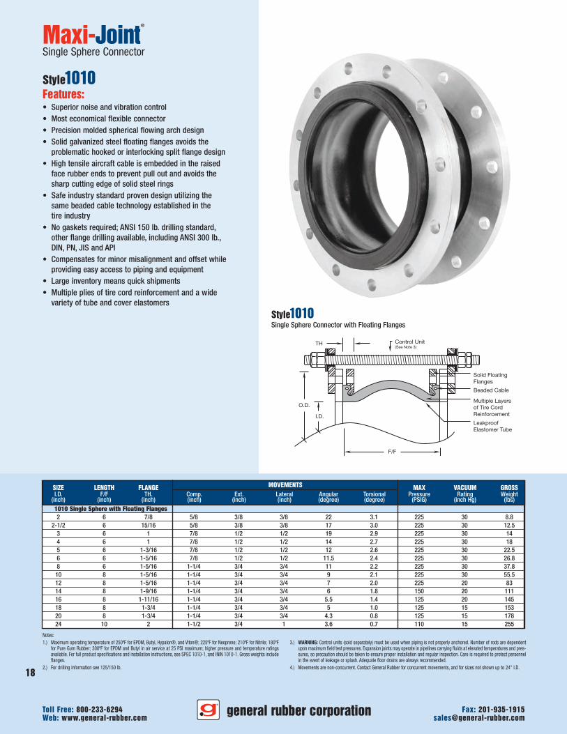
Maxi-Joint®
Single Sphere Connector
Style1010Features:• Superior noise and vibration control• Most economical flexible connector• Precision molded spherical flowing arch design• Solid galvanized steel floating flanges avoids the
problematic hooked or interlocking split flange design• High tensile aircraft cable is embedded in the raised
face rubber ends to prevent pull out and avoids thesharp cutting edge of solid steel rings
• Safe industry standard proven design utilizing thesame beaded cable technology established in thetire industry
• No gaskets required; ANSI 150 lb. drilling standard,other flange drilling available, including ANSI 300 lb.,DIN, PN, JIS and API
• Compensates for minor misalignment and offset whileproviding easy access to piping and equipment
• Large inventory means quick shipments• Multiple plies of tire cord reinforcement and a wide
variety of tube and cover elastomers
SIZE LENGTH FLANGE MOVEMENTS MAX VACUUM GROSSI.D. F/F TH. Comp. Ext. Lateral Angular Torsional Pressure Rating Weight
(inch) (inch) (inch) (inch) (inch) (inch) (degree) (degree) (PSIG) (inch Hg) (lbs)1010 Single Sphere with Floating Flanges2 6 7/8 5/8 3/8 3/8 22 3.1 225 30 8.8
2-1/2 6 15/16 5/8 3/8 3/8 17 3.0 225 30 12.53 6 1 7/8 1/2 1/2 19 2.9 225 30 144 6 1 7/8 1/2 1/2 14 2.7 225 30 185 6 1-3/16 7/8 1/2 1/2 12 2.6 225 30 22.56 6 1-5/16 7/8 1/2 1/2 11.5 2.4 225 30 26.88 6 1-5/16 1-1/4 3/4 3/4 11 2.2 225 30 37.8
10 8 1-5/16 1-1/4 3/4 3/4 9 2.1 225 30 55.512 8 1-5/16 1-1/4 3/4 3/4 7 2.0 225 20 8314 8 1-9/16 1-1/4 3/4 3/4 6 1.8 150 20 11116 8 1-11/16 1-1/4 3/4 3/4 5.5 1.4 125 20 14518 8 1-3/4 1-1/4 3/4 3/4 5 1.0 125 15 15320 8 1-3/4 1-1/4 3/4 3/4 4.3 0.8 125 15 17824 10 2 1-1/2 3/4 1 3.6 0.7 110 15 255
Style1010Single Sphere Connector with Floating Flanges
general rubber corporationWeb: www.general-rubber.com [email protected] Free: 800-233-6294 Fax: 201-935-1915
18
F/F
I.D.
O.D.
TH Control Unit(See Note 3)
Center Root Ring Solid FloatingFlanges
Multiple Layersof Tire CordReinforcement
Beaded Cable
LeakproofElastomer Tube
Notes:1.) Maximum operating temperature of 250ºF for EPDM, Butyl, Hypalon®, and Viton®; 225ºF for Neoprene; 210ºF for Nitrile; 180ºF
for Pure Gum Rubber; 300ºF for EPDM and Butyl in air service at 25 PSI maximum; higher pressure and temperature ratingsavailable. For full product specifications and installation instructions, see SPEC 1020-1, and ININ 1020-1. Gross weights includeflanges.
2.) For drilling information see 125/150 lb.
3.) WARNING: Control units (sold separately) must be used when piping is not properly anchored. Number of rods are dependentupon maximum field test pressures. Expansion joints may operate in pipelines carrying fluids at elevated temperatures and pres-sures, so precaution should be taken to ensure proper installation and regular inspection. Care is required to protect personnelin the event of leakage or splash. Adequate floor drains are always recommended.
4.) Movements are non-concurrent. Contact General Rubber for concurrent movements, and for sizes not shown up to 24" I.D.
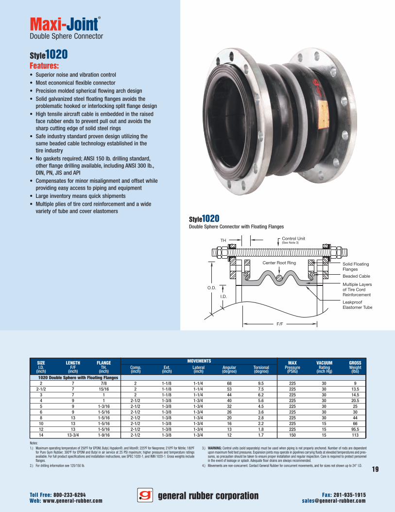
Maxi-Joint®
Double Sphere Connector
Style1020Features:• Superior noise and vibration control• Most economical flexible connector• Precision molded spherical flowing arch design• Solid galvanized steel floating flanges avoids the
problematic hooked or interlocking split flange design• High tensile aircraft cable is embedded in the raised
face rubber ends to prevent pull out and avoids thesharp cutting edge of solid steel rings
• Safe industry standard proven design utilizing thesame beaded cable technology established in thetire industry
• No gaskets required; ANSI 150 lb. drilling standard,other flange drilling available, including ANSI 300 lb.,DIN, PN, JIS and API
• Compensates for minor misalignment and offset whileproviding easy access to piping and equipment
• Large inventory means quick shipments• Multiple plies of tire cord reinforcement and a wide
variety of tube and cover elastomers
SIZE LENGTH FLANGE MOVEMENTS MAX VACUUM GROSSI.D. F/F TH. Comp. Ext. Lateral Angular Torsional Pressure Rating Weight
(inch) (inch) (inch) (inch) (inch) (inch) (degree) (degree) (PSIG) (inch Hg) (lbs)1020 Double Sphere with Floating Flanges2 7 7/8 2 1-1/8 1-1/4 68 9.5 225 30 9
2-1/2 7 15/16 2 1-1/8 1-1/4 53 7.5 225 30 13.53 7 1 2 1-1/8 1-1/4 44 6.2 225 30 14.54 9 1 2-1/2 1-3/8 1-3/4 40 5.6 225 30 20.55 9 1-3/16 2-1/2 1-3/8 1-3/4 32 4.5 225 30 256 9 1-5/16 2-1/2 1-3/8 1-3/4 26 3.6 225 30 308 13 1-5/16 2-1/2 1-3/8 1-3/4 20 2.8 225 30 44
10 13 1-5/16 2-1/2 1-3/8 1-3/4 16 2.2 225 15 6612 13 1-5/16 2-1/2 1-3/8 1-3/4 13 1.8 225 15 95.514 13-3/4 1-9/16 2-1/2 1-3/8 1-3/4 12 1.7 150 15 113
Style1020Double Sphere Connector with Floating Flanges
general rubber corporationWeb: www.general-rubber.com [email protected] Free: 800-233-6294 Fax: 201-935-1915
19
general rubber corporation
20
Web: www.general-rubber.com [email protected] Free: 800-233-6294 Fax: 201-935-1915
F/F
Beaded Cable
Center Root Ring
Notes:1.) Maximum operating temperature of 250ºF for EPDM, Butyl, Hypalon®, and Viton®; 225ºF for Neoprene; 210ºF for Nitrile; 180ºF
for Pure Gum Rubber; 300ºF for EPDM and Butyl in air service at 25 PSI maximum; higher pressure and temperature ratingsavailable. For full product specifications and installation instructions, see SPEC 1010-1, and ININ 1010-1. Gross weights includeflanges.
2.) For drilling information see 125/150 lb.
3.) WARNING: Control units (sold separately) must be used when piping is not properly anchored. Number of rods are dependentupon maximum field test pressures. Expansion joints may operate in pipelines carrying fluids at elevated temperatures and pres-sures, so precaution should be taken to ensure proper installation and regular inspection. Care is required to protect personnelin the event of leakage or splash. Adequate floor drains are always recommended.
4.) Movements are non-concurrent. Contact General Rubber for concurrent movements, and for sizes not shown up to 24" I.D.
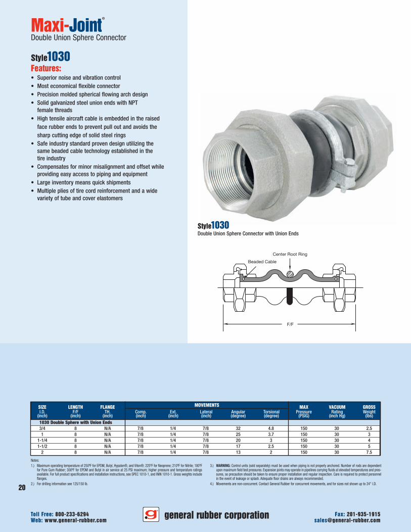
Maxi-Joint®
Double Union Sphere Connector
Style1030Features:• Superior noise and vibration control• Most economical flexible connector• Precision molded spherical flowing arch design• Solid galvanized steel union ends with NPT
female threads• High tensile aircraft cable is embedded in the raised
face rubber ends to prevent pull out and avoids thesharp cutting edge of solid steel rings
• Safe industry standard proven design utilizing thesame beaded cable technology established in thetire industry
• Compensates for minor misalignment and offset whileproviding easy access to piping and equipment
• Large inventory means quick shipments• Multiple plies of tire cord reinforcement and a wide
variety of tube and cover elastomers
Style1030Double Union Sphere Connector with Union Ends
SIZE LENGTH FLANGE MOVEMENTS MAX VACUUM GROSSI.D. F/F TH. Comp. Ext. Lateral Angular Torsional Pressure Rating Weight
(inch) (inch) (inch) (inch) (inch) (inch) (degree) (degree) (PSIG) (inch Hg) (lbs)1030 Double Sphere with Union Ends3/4 8 N/A 7/8 1/4 7/8 32 4.8 150 30 2.51 8 N/A 7/8 1/4 7/8 25 3.7 150 30 3
1-1/4 8 N/A 7/8 1/4 7/8 20 3 150 30 41-1/2 8 N/A 7/8 1/4 7/8 17 2.5 150 30 5
2 8 N/A 7/8 1/4 7/8 13 2 150 30 7.5
F/FI.D.
ANSI 125/150 lb.Flange withThreaded Holes
Stainless SteelReinforcing Ring
Molded Teflon®
(PTFE) Bellows
TH
Integral Limit Bolt
Teflon®
Grommet
Notes:1.) Movements are non-concurrent. Contact General Rubber for concurrent movement, and for sizes not shown up to 24" I.D.2.) For full product specifications and installation instructions, see SPEC 3302-1 and ININ 3302-1.
3.) WARNING:WARNING: Control units (integral limit bolts) must be used when piping is not properly anchored. Expansion joints mayoperate in pipelines carrying fluids at elevated temperatures and pressures, so precaution should be taken to ensure properinstallation and regular inspection. Care is required to protect personnel in the event of leakage or splash. Adequate floor drainsare always recommended.
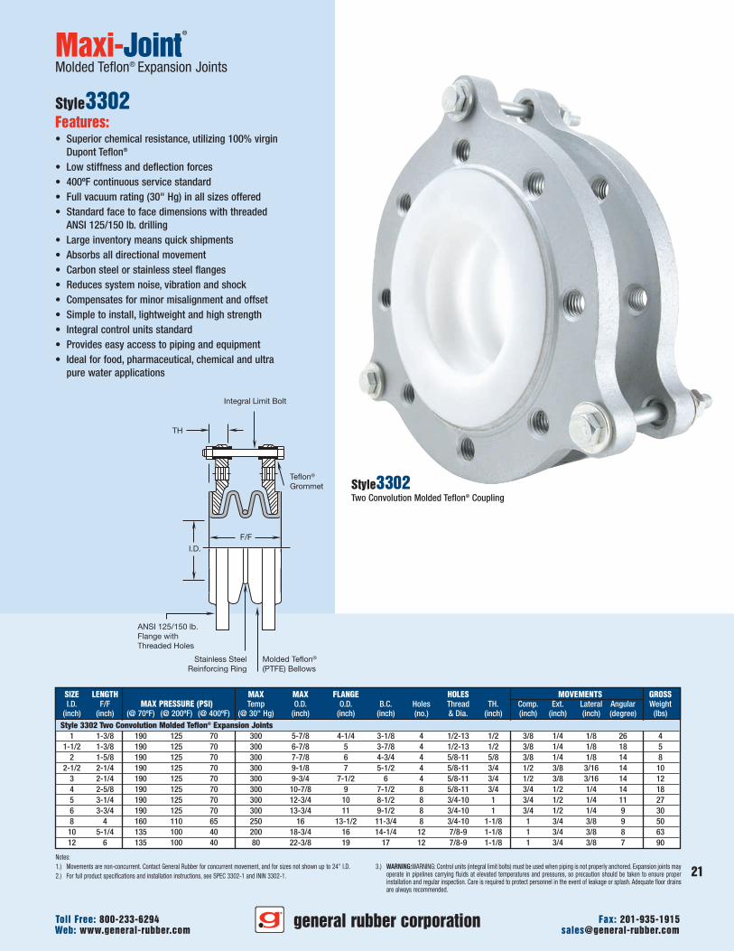
Maxi-Joint®
Molded Teflon® Expansion Joints
Style3302Features:• Superior chemical resistance, utilizing 100% virgin
Dupont Teflon®
• Low stiffness and deflection forces• 400ºF continuous service standard• Full vacuum rating (30" Hg) in all sizes offered• Standard face to face dimensions with threaded
ANSI 125/150 lb. drilling• Large inventory means quick shipments• Absorbs all directional movement• Carbon steel or stainless steel flanges• Reduces system noise, vibration and shock• Compensates for minor misalignment and offset• Simple to install, lightweight and high strength• Integral control units standard• Provides easy access to piping and equipment• Ideal for food, pharmaceutical, chemical and ultra
pure water applications
Style3302Two Convolution Molded Teflon® Coupling
SIZE LENGTH MAX MAX FLANGE HOLES MOVEMENTS GROSSI.D. F/F MAX PRESSURE (PSI) Temp O.D. O.D. B.C. Holes Thread TH. Comp. Ext. Lateral Angular Weight
(inch) (inch) (@ 70ºF) (@ 200ºF) (@ 400ºF) (@ 30" Hg) (inch) (inch) (inch) (no.) & Dia. (inch) (inch) (inch) (inch) (degree) (lbs)Style 3302 Two Convolution Molded Teflon® Expansion Joints
1 1-3/8 190 125 70 300 5-7/8 4-1/4 3-1/8 4 1/2-13 1/2 3/8 1/4 1/8 26 41-1/2 1-3/8 190 125 70 300 6-7/8 5 3-7/8 4 1/2-13 1/2 3/8 1/4 1/8 18 5
2 1-5/8 190 125 70 300 7-7/8 6 4-3/4 4 5/8-11 5/8 3/8 1/4 1/8 14 82-1/2 2-1/4 190 125 70 300 9-1/8 7 5-1/2 4 5/8-11 3/4 1/2 3/8 3/16 14 10
3 2-1/4 190 125 70 300 9-3/4 7-1/2 6 4 5/8-11 3/4 1/2 3/8 3/16 14 124 2-5/8 190 125 70 300 10-7/8 9 7-1/2 8 5/8-11 3/4 3/4 1/2 1/4 14 185 3-1/4 190 125 70 300 12-3/4 10 8-1/2 8 3/4-10 1 3/4 1/2 1/4 11 276 3-3/4 190 125 70 300 13-3/4 11 9-1/2 8 3/4-10 1 3/4 1/2 1/4 9 308 4 160 110 65 250 16 13-1/2 11-3/4 8 3/4-10 1-1/8 1 3/4 3/8 9 50
10 5-1/4 135 100 40 200 18-3/4 16 14-1/4 12 7/8-9 1-1/8 1 3/4 3/8 8 6312 6 135 100 40 80 22-3/8 19 17 12 7/8-9 1-1/8 1 3/4 3/8 7 90
general rubber corporationWeb: www.general-rubber.com [email protected] Free: 800-233-6294 Fax: 201-935-1915
21
Stainless SteelReinforcing Ring
Molded Teflon®
(PTFE) Bellows
Integral Limit Bolt
Teflon®
GrommetTH
F/FI.D.
ANSI 125/150 lb.Flange withThreaded Holes
Notes:1.) Movements are non-concurrent. Contact General Rubber for concurrent movement, and for sizes not shown up to 24" I.D.2.) For full product specifications and installation instructions, see SPEC 3303-1 and ININ 3303-1.
3.) WARNING: Control units (integral limit bolts) must be used when piping is not properly anchored. Expansion joints may operatein pipelines carrying fluids at elevated temperatures and pressures, so precaution should be taken to ensure proper installationand regular inspection. Care is required to protect personnel in the event of leakage or splash. Adequate floor drains are alwaysrecommended.
Maxi-Joint®
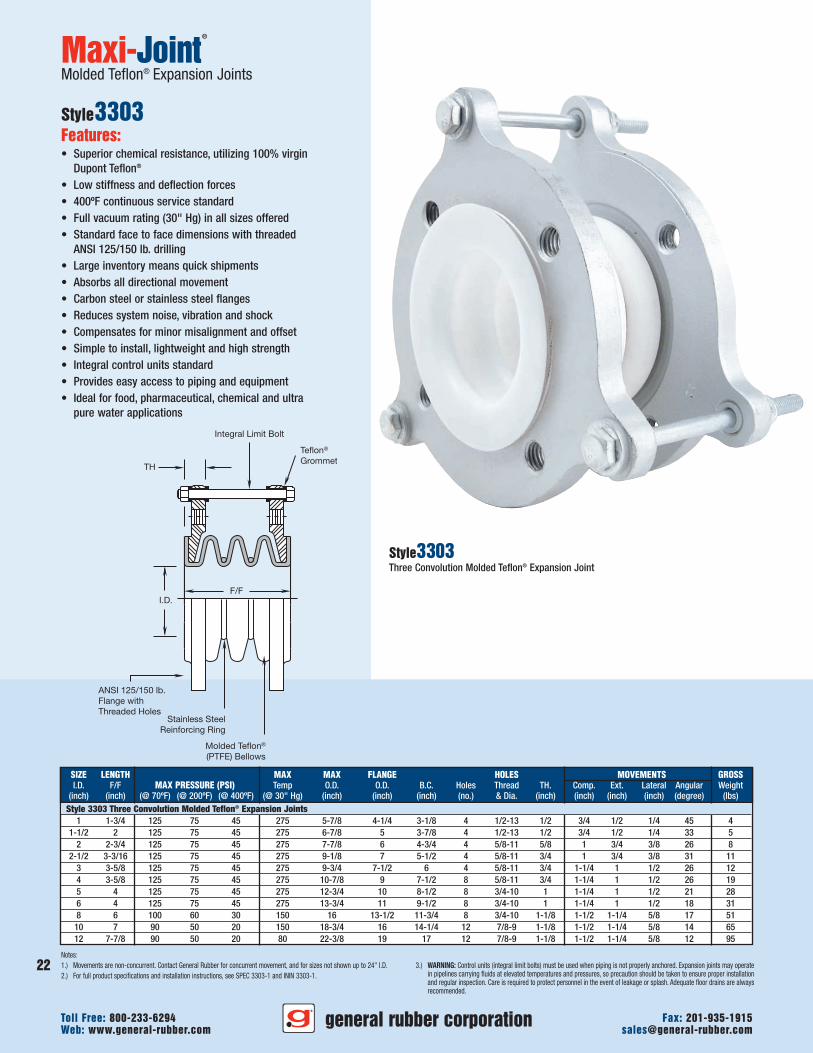
Molded Teflon® Expansion Joints
Style3303Features:• Superior chemical resistance, utilizing 100% virgin
Dupont Teflon®
• Low stiffness and deflection forces• 400ºF continuous service standard• Full vacuum rating (30" Hg) in all sizes offered• Standard face to face dimensions with threaded
ANSI 125/150 lb. drilling• Large inventory means quick shipments• Absorbs all directional movement• Carbon steel or stainless steel flanges• Reduces system noise, vibration and shock• Compensates for minor misalignment and offset• Simple to install, lightweight and high strength• Integral control units standard• Provides easy access to piping and equipment• Ideal for food, pharmaceutical, chemical and ultra
pure water applications
Style3303Three Convolution Molded Teflon® Expansion Joint
SIZE LENGTH MAX MAX FLANGE HOLES MOVEMENTS GROSSI.D. F/F MAX PRESSURE (PSI) Temp O.D. O.D. B.C. Holes Thread TH. Comp. Ext. Lateral Angular Weight
(inch) (inch) (@ 70ºF) (@ 200ºF) (@ 400ºF) (@ 30" Hg) (inch) (inch) (inch) (no.) & Dia. (inch) (inch) (inch) (inch) (degree) (lbs)Style 3303 Three Convolution Molded Teflon® Expansion Joints
1 1-3/4 125 75 45 275 5-7/8 4-1/4 3-1/8 4 1/2-13 1/2 3/4 1/2 1/4 45 41-1/2 2 125 75 45 275 6-7/8 5 3-7/8 4 1/2-13 1/2 3/4 1/2 1/4 33 5
2 2-3/4 125 75 45 275 7-7/8 6 4-3/4 4 5/8-11 5/8 1 3/4 3/8 26 82-1/2 3-3/16 125 75 45 275 9-1/8 7 5-1/2 4 5/8-11 3/4 1 3/4 3/8 31 11
3 3-5/8 125 75 45 275 9-3/4 7-1/2 6 4 5/8-11 3/4 1-1/4 1 1/2 26 124 3-5/8 125 75 45 275 10-7/8 9 7-1/2 8 5/8-11 3/4 1-1/4 1 1/2 26 195 4 125 75 45 275 12-3/4 10 8-1/2 8 3/4-10 1 1-1/4 1 1/2 21 286 4 125 75 45 275 13-3/4 11 9-1/2 8 3/4-10 1 1-1/4 1 1/2 18 318 6 100 60 30 150 16 13-1/2 11-3/4 8 3/4-10 1-1/8 1-1/2 1-1/4 5/8 17 51
10 7 90 50 20 150 18-3/4 16 14-1/4 12 7/8-9 1-1/8 1-1/2 1-1/4 5/8 14 6512 7-7/8 90 50 20 80 22-3/8 19 17 12 7/8-9 1-1/8 1-1/2 1-1/4 5/8 12 95
general rubber corporationWeb: www.general-rubber.com [email protected] Free: 800-233-6294 Fax: 201-935-1915
22
23
general rubber corporationWeb: www.general-rubber.com [email protected] Free: 800-233-6294 Fax: 201-935-1915
F/FI.D.
Stainless SteelReinforcing Ring
Double LayerMolded Teflon®
(PTFE) Bellows
TH
Stainless SteelStabilizer Guides
Integral Limit Bolt
Teflon® Grommet
ANSI 125/150 lb.Flange withThreaded Holes
Notes:1.) Movements are non-concurrent. Contact General Rubber for concurrent movement, and for sizes not shown up to 24" I.D.2.) For full product specifications and installation instructions, see SPEC 3305-1 and ININ 3305-1.
3.) WARNING: Control units (integral limit bolts) must be used when piping is not properly anchored. Expansion joints may operatein pipelines carrying fluids at elevated temperatures and pressures, so precaution should be taken to ensure proper installationand regular inspection. Care is required to protect personnel in the event of leakage or splash. Adequate floor drains are alwaysrecommended.
Maxi-Joint®
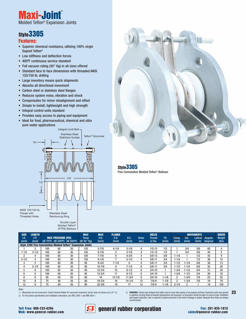
Molded Teflon® Expansion Joints
Style3305Features:• Superior chemical resistance, utilizing 100% virgin
Dupont Teflon®
• Low stiffness and deflection forces• 400ºF continuous service standard• Full vacuum rating (30" Hg) in all sizes offered• Standard face to face dimensions with threaded ANSI
125/150 lb. drilling• Large inventory means quick shipments• Absorbs all directional movement• Carbon steel or stainless steel flanges• Reduces system noise, vibration and shock• Compensates for minor misalignment and offset• Simple to install, lightweight and high strength• Integral control units standard• Provides easy access to piping and equipment• Ideal for food, pharmaceutical, chemical and ultra
pure water applications
Style3305Five Convolution Molded Teflon® Bellows
SIZE LENGTH MAX MAX FLANGE HOLES MOVEMENTS GROSSI.D. F/F MAX PRESSURE (PSI) Temp O.D. O.D. B.C. Holes Thread TH. Comp. Ext. Lateral Angular Weight
(inch) (inch) (@ 70ºF) (@ 200ºF) (@ 400ºF) (@ 30" Hg) (inch) (inch) (inch) (no.) & Dia. (inch) (inch) (inch) (inch) (degree) (lbs)Style 3305 Five Convolution Molded Teflon® Expansion Joints
1 3 100 65 30 120 5-7/8 4-1/4 3-1/8 4 1/2-13 1/2 1 3/4 3/8 65 41-1/2 3-1/2 100 65 30 120 6-7/8 5 3-7/8 4 1/2-13 1/2 1 3/4 3/8 45 5
2 4 100 65 30 120 7-7/8 6 4-3/4 4 5/8-13 5/8 1-1/4 1 1/2 43 92-1/2 4 100 65 30 120 9-1/8 7 5-1/2 4 5/8-11 3/4 1-1/4 1 1/2 38 12
3 5 100 65 30 95 9-3/4 7-1/2 6 4 5/8-11 3/4 1-1/2 1-1/4 5/8 38 134 5-1/4 100 65 30 95 10-7/8 9 7-1/2 8 5/8-11 3/4 1-1/2 1-1/4 5/8 32 205 6 100 65 30 95 12-3/4 10 8-1/2 8 3/4-10 1 1-3/4 1-1/2 3/4 31 306 6 100 65 30 95 13-3/4 11 9-1/2 8 3/4-10 1 1-3/4 1-1/2 3/4 26 338 8 85 50 25 80 16 13-1/2 11-3/4 8 3/4-10 1-1/8 2 1-3/4 7/8 23 52
10 8 75 40 20 80 18-3/4 16 14-1/4 12 7/8-9 1-1/8 2 1-3/4 7/8 19 7012 9 75 40 20 80 22-3/8 19 17 12 7/8-9 1-1/8 2-1/4 2 1 18 105
ActualI.D.
O.A.L.
Stainless SteelScrew Clamps Tire Cord
Reinforcement
LeakproofElastomerTube
1/4"Nom.
O.A.L.
ActualI.D.
1/4"Nom.
Stainless SteelScrew Clamps
LeakproofElastomerTube
Tire CordReinforcement
1/4"Nom.
ActualI.D.
O.A.L.
Stainless SteelScrew Clamps Tire Cord
Reinforcement
LeakproofElastomerTube
Notes:1.) Expansion joints are sized to slip over schedule 40 pipe. Other I.D. dimensions are available.2.) Movements are non-concurrent movements. Contact General Rubber for concurrent movements, and for sizes not shown up to 96" I.D.3.) For full product specifications and installation instructions, see SPEC 1081-1, 1082-1 & 1083-1 and ININ 1081-1,1082-1 & 1083-1.
4.) WARNING: Anchors should be used to resist the pressure thrust force and isolate movements between expansion joints.Expansion joints may operate in pipelines carrying fluids at elevated temperatures and pressures, so precaution should be takento ensure proper installation and regular inspection. Care is required to protect personnel in the event of leakage or splash.Adequate floor drains are always recommended.
Maxi-Joint®
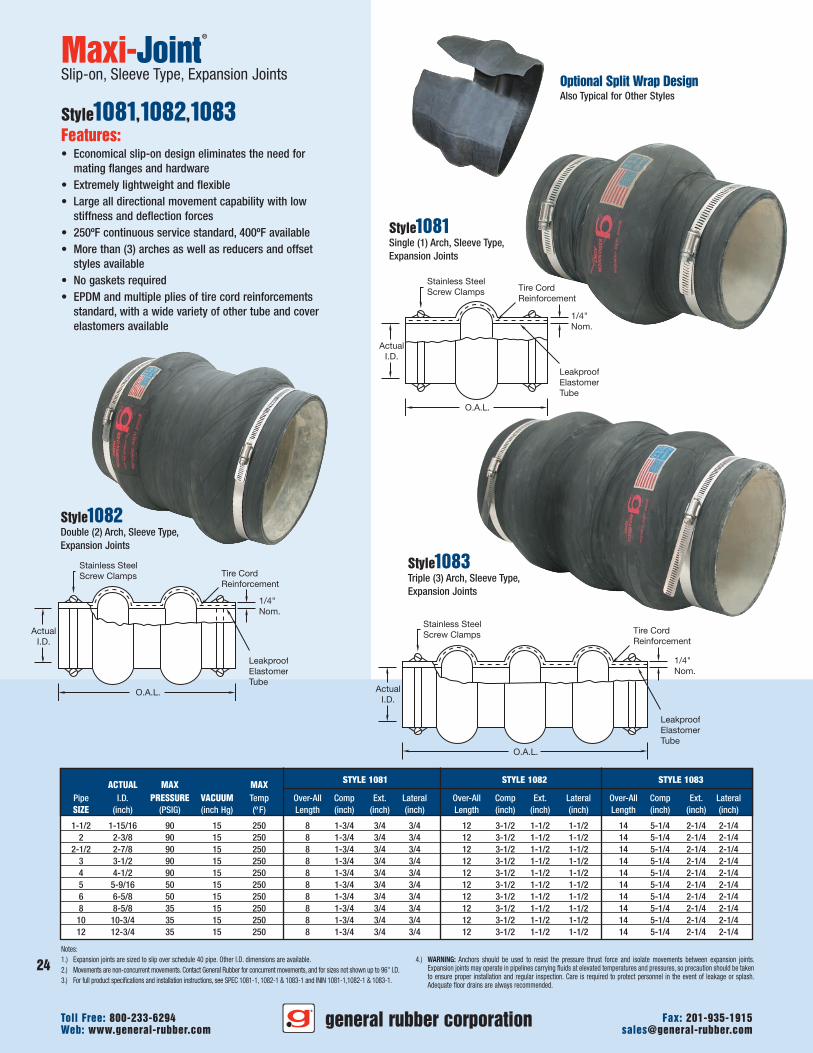
Slip-on, Sleeve Type, Expansion Joints
Style1081,1082,1083Features:• Economical slip-on design eliminates the need for
mating flanges and hardware• Extremely lightweight and flexible• Large all directional movement capability with low
stiffness and deflection forces• 250ºF continuous service standard, 400ºF available• More than (3) arches as well as reducers and offset
styles available• No gaskets required• EPDM and multiple plies of tire cord reinforcements
standard, with a wide variety of other tube and coverelastomers available
Style1081Single (1) Arch, Sleeve Type,Expansion Joints
STYLE 1081 STYLE 1082 STYLE 1083ACTUAL MAX MAXPipe I.D. PRESSURE VACUUM Temp Over-All Comp Ext. Lateral Over-All Comp Ext. Lateral Over-All Comp Ext. LateralSIZE (inch) (PSIG) (inch Hg) (º F) Length (inch) (inch) (inch) Length (inch) (inch) (inch) Length (inch) (inch) (inch)
1-1/2 1-15/16 90 15 250 8 1-3/4 3/4 3/4 12 3-1/2 1-1/2 1-1/2 14 5-1/4 2-1/4 2-1/42 2-3/8 90 15 250 8 1-3/4 3/4 3/4 12 3-1/2 1-1/2 1-1/2 14 5-1/4 2-1/4 2-1/4
2-1/2 2-7/8 90 15 250 8 1-3/4 3/4 3/4 12 3-1/2 1-1/2 1-1/2 14 5-1/4 2-1/4 2-1/43 3-1/2 90 15 250 8 1-3/4 3/4 3/4 12 3-1/2 1-1/2 1-1/2 14 5-1/4 2-1/4 2-1/44 4-1/2 90 15 250 8 1-3/4 3/4 3/4 12 3-1/2 1-1/2 1-1/2 14 5-1/4 2-1/4 2-1/45 5-9/16 50 15 250 8 1-3/4 3/4 3/4 12 3-1/2 1-1/2 1-1/2 14 5-1/4 2-1/4 2-1/46 6-5/8 50 15 250 8 1-3/4 3/4 3/4 12 3-1/2 1-1/2 1-1/2 14 5-1/4 2-1/4 2-1/48 8-5/8 35 15 250 8 1-3/4 3/4 3/4 12 3-1/2 1-1/2 1-1/2 14 5-1/4 2-1/4 2-1/4
10 10-3/4 35 15 250 8 1-3/4 3/4 3/4 12 3-1/2 1-1/2 1-1/2 14 5-1/4 2-1/4 2-1/412 12-3/4 35 15 250 8 1-3/4 3/4 3/4 12 3-1/2 1-1/2 1-1/2 14 5-1/4 2-1/4 2-1/4
Optional Split Wrap DesignAlso Typical for Other Styles
Style1083Triple (3) Arch, Sleeve Type,Expansion Joints
Style1082Double (2) Arch, Sleeve Type,Expansion Joints
general rubber corporationWeb: www.general-rubber.com [email protected] Free: 800-233-6294 Fax: 201-935-1915
24
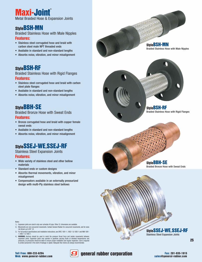
25
general rubber corporationWeb: www.general-rubber.com [email protected] Free: 800-233-6294 Fax: 201-935-1915
Maxi-Joint®
Metal Braided Hose & Expansion Joints
StyleBSH-MNBraided Stainless Hose with Male NipplesFeatures:• Stainless steel corrugated hose and braid with
carbon steel male NPT threaded ends• Available in standard and non-standard lengths• Absorbs noise, vibration, and minor misalignment
StyleBSH-RFBraided Stainless Hose with Rigid FlangesFeatures:• Stainless steel corrugated hose and braid with carbon
steel plate flanges• Available in standard and non-standard lengths• Absorbs noise, vibration, and minor misalignment
StyleBBH-SEBraided Bronze Hose with Sweat EndsFeatures:• Bronze corrugated hose and braid with copper female
sweat ends• Available in standard and non-standard lengths• Absorbs noise, vibration, and minor misalignment
StyleSSEJ-WE,SSEJ-RFStainless Steel Expansion JointsFeatures:• Wide variety of stainless steel and other bellow
materials• Standard ends or custom designs• Absorbs thermal movements, vibration, and minor
misalignment• Compensators available in an externally pressurized
design with multi-Ply stainless steel bellows
StyleBSH-MNBraided Stainless Hose with Male Nipples
StyleBSH-RFBraided Stainless Hose with Rigid Flanges
StyleBBH-SEBraided Bronze Hose with Sweat Ends
StyleSSEJ-WE,SSEJ-RFStainless Steel Expansion Joints
Notes:1.) Expansion joints are sized to slip over schedule 40 pipe. Other I.D. dimensions are available.2.) Movements are non-concurrent movements. Contact General Rubber for concurrent movements, and for sizes
not shown up to 96" I.D.3.) For full product specifications and installation instructions, see SPEC 1081-1, 1082-1 & 1083-1 and ININ 1081-
1,1082-1 & 1083-1.4.) WARNING: Anchors should be used to resist the pressure thrust force and isolate movements between
expansion joints. Expansion joints may operate in pipelines carrying fluids at elevated temperatures andpressures, so precaution should be taken to ensure proper installation and regular inspection. Care is requiredto protect personnel in the event of leakage or splash. Adequate floor drains are always recommended.
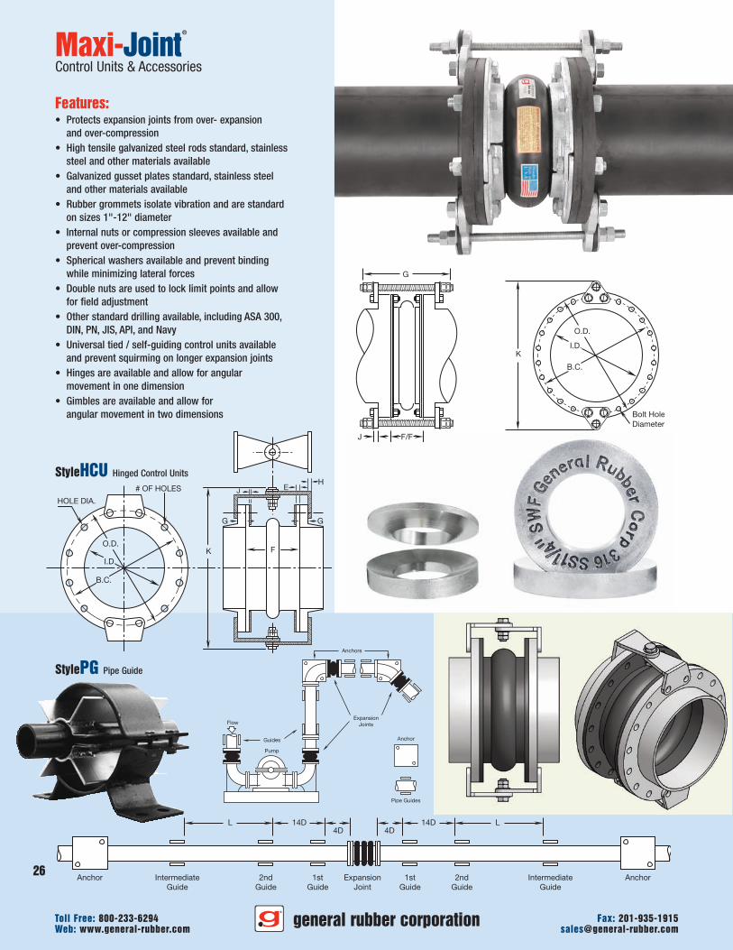
G
F/FJ
K
Bolt HoleDiameter
I.D.
B.C.
O.D.
Pump
Guides
FlowExpansion
Joints
Anchors
Pipe Guides
Anchor
L14D4D
AnchorIntermediateGuide
ExpansionJoint
2ndGuide
1stGuide
L 14D4D
Anchor IntermediateGuide
2ndGuide
1stGuide
StyleHCU Hinged Control Units
Maxi-Joint®
Control Units & Accessories
Features:• Protects expansion joints from over- expansion
and over-compression• High tensile galvanized steel rods standard, stainless
steel and other materials available• Galvanized gusset plates standard, stainless steel
and other materials available• Rubber grommets isolate vibration and are standard
on sizes 1"-12" diameter• Internal nuts or compression sleeves available and
prevent over-compression• Spherical washers available and prevent binding
while minimizing lateral forces• Double nuts are used to lock limit points and allow
for field adjustment• Other standard drilling available, including ASA 300,
DIN, PN, JIS, API, and Navy• Universal tied / self-guiding control units available
and prevent squirming on longer expansion joints• Hinges are available and allow for angular
movement in one dimension• Gimbles are available and allow for
angular movement in two dimensions
StylePG Pipe Guide
general rubber corporationWeb: www.general-rubber.com [email protected] Free: 800-233-6294 Fax: 201-935-1915
26
H
G
HOLE DIA.
# OF HOLES E
G
FKI.D.
B.C.
O.D.
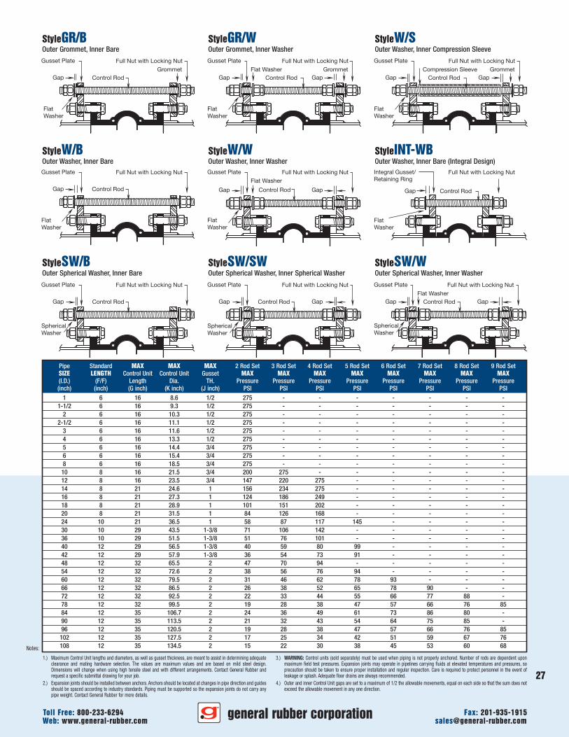
27
general rubber corporationWeb: www.general-rubber.com [email protected] Free: 800-233-6294 Fax: 201-935-1915
1.) Maximum Control Unit lengths and diameters, as well as gusset thickness, are meant to assist in determining adequateclearance and mating hardware selection. The values are maximum values and are based on mild steel design.Dimensions will change when using high tensile steel and with different arrangements. Contact General Rubber andrequest a specific submittal drawing for your job.
2.) Expansion joints should be installed between anchors. Anchors should be located at changes in pipe direction and guidesshould be spaced according to industry standards. Piping must be supported so the expansion joints do not carry anypipe weight. Contact General Rubber for more details.
Notes:
StyleGR/BOuter Grommet, Inner Bare
StyleGR/WOuter Grommet, Inner Washer
StyleW/SOuter Washer, Inner Compression Sleeve
Gusset Plate Full Nut with Locking NutGrommet
Control RodGap
FlatWasher
StyleW/BOuter Washer, Inner Bare
StyleW/WOuter Washer, Inner Washer
StyleINT-WBOuter Washer, Inner Bare (Integral Design)
StyleSW/BOuter Spherical Washer, Inner Bare
StyleSW/SWOuter Spherical Washer, Inner Spherical Washer
StyleSW/WOuter Spherical Washer, Inner Washer
Gusset Plate Full Nut with Locking NutGrommetFlat Washer
Control RodGap Gap
FlatWasher
Gusset Plate Full Nut with Locking NutGrommetCompression Sleeve
Control RodGap Gap
FlatWasher
Gusset Plate Full Nut with Locking Nut
Control RodGap
FlatWasher
Gusset Plate Full Nut with Locking NutFlat Washer
Control RodGap Gap
FlatWasher
Integral Gusset/Retaining Ring
Full Nut with Locking Nut
Control RodGap
FlatWasher
Gusset Plate Full Nut with Locking Nut
Control RodGap
SphericalWasher
Gusset Plate Full Nut with Locking Nut
Control RodGap Gap
SphericalWasher
Gusset Plate Full Nut with Locking NutFlat Washer
Control RodGap Gap
SphericalWasher
Pipe Standard MAX MAX MAX 2 Rod Set 3 Rod Set 4 Rod Set 5 Rod Set 6 Rod Set 7 Rod Set 8 Rod Set 9 Rod SetSIZE LENGTH Control Unit Control Unit Gusset MAX MAX MAX MAX MAX MAX MAX MAX(I.D.) (F/F) Length Dia. TH. Pressure Pressure Pressure Pressure Pressure Pressure Pressure Pressure(inch) (inch) (G inch) (K inch) (J inch) PSI PSI PSI PSI PSI PSI PSI PSI
1 6 16 8.6 1/2 275 - - - - - - -1-1/2 6 16 9.3 1/2 275 - - - - - - -
2 6 16 10.3 1/2 275 - - - - - - -2-1/2 6 16 11.1 1/2 275 - - - - - - -
3 6 16 11.6 1/2 275 - - - - - - -4 6 16 13.3 1/2 275 - - - - - - -5 6 16 14.4 3/4 275 - - - - - - -6 6 16 15.4 3/4 275 - - - - - - -8 6 16 18.5 3/4 275 - - - - - - -
10 8 16 21.5 3/4 200 275 - - - - - -12 8 16 23.5 3/4 147 220 275 - - - - -14 8 21 24.6 1 156 234 275 - - - - -16 8 21 27.3 1 124 186 249 - - - - -18 8 21 28.9 1 101 151 202 - - - - -20 8 21 31.5 1 84 126 168 - - - - -24 10 21 36.5 1 58 87 117 145 - - - -30 10 29 43.5 1-3/8 71 106 142 - - - - -36 10 29 51.5 1-3/8 51 76 101 - - - - -40 12 29 56.5 1-3/8 40 59 80 99 - - - -42 12 29 57.9 1-3/8 36 54 73 91 - - - -48 12 32 65.5 2 47 70 94 - - - - -54 12 32 72.6 2 38 56 76 94 - - - -60 12 32 79.5 2 31 46 62 78 93 - - -66 12 32 86.5 2 26 38 52 65 78 90 - -72 12 32 92.5 2 22 33 44 55 66 77 88 -78 12 32 99.5 2 19 28 38 47 57 66 76 8584 12 35 106.7 2 24 36 49 61 73 86 80 -90 12 35 113.5 2 21 32 43 54 64 75 85 -96 12 35 120.5 2 19 28 38 47 57 66 76 85
102 12 35 127.5 2 17 25 34 42 51 59 67 76108 12 35 134.5 2 15 22 30 38 45 53 60 68
3.) WARNING: Control units (sold separately) must be used when piping is not properly anchored. Number of rods are dependent uponmaximum field test pressures. Expansion joints may operate in pipelines carrying fluids at elevated temperatures and pressures, soprecaution should be taken to ensure proper installation and regular inspection. Care is required to protect personnel in the event ofleakage or splash. Adequate floor drains are always recommended.
4.) Outer and inner Control Unit gaps are set to a maximum of 1/2 the allowable movements, equal on each side so that the sum does notexceed the allowable movement in any one direction.
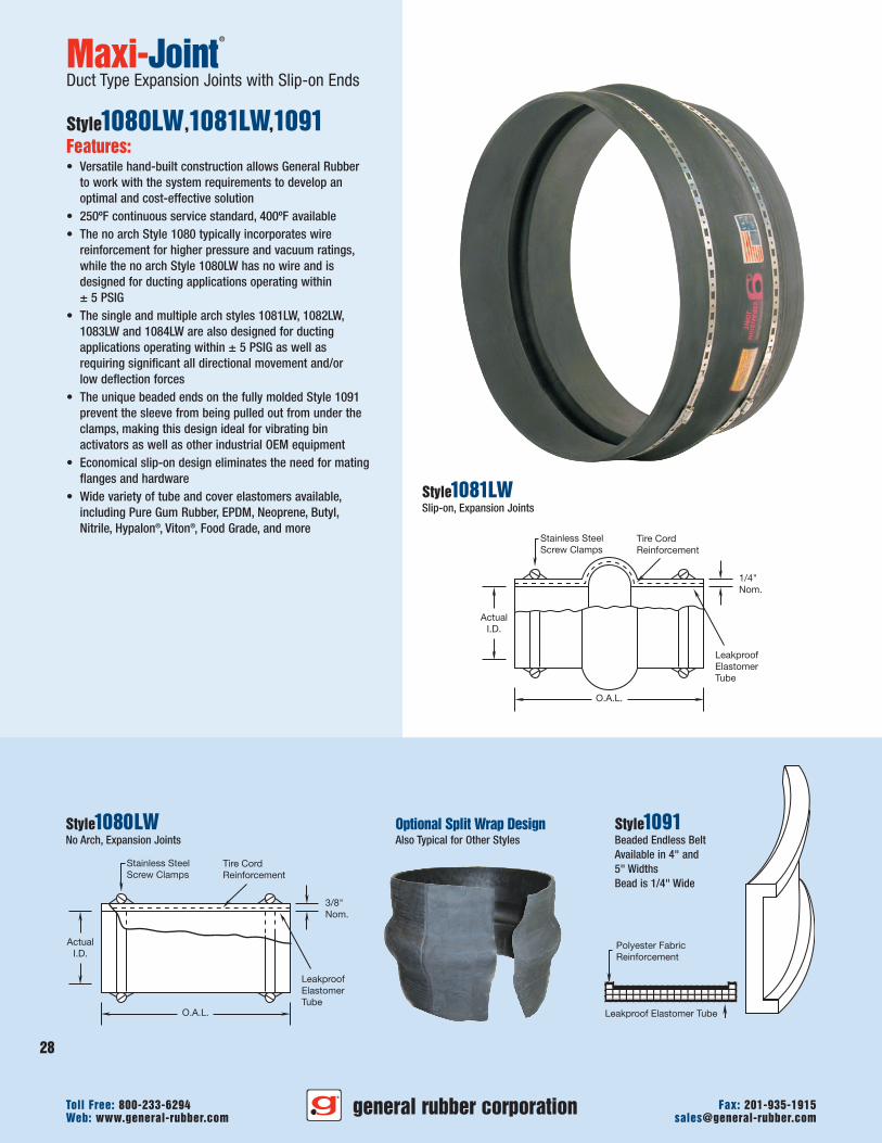
Leakproof Elastomer Tube
Polyester FabricReinforcement
ActualI.D.
O.A.L.
Stainless SteelScrew Clamps
1/4"Nom.
LeakproofElastomerTube
Tire CordReinforcement
3/8"Nom.
ActualI.D.
O.A.L.
LeakproofElastomerTube
Stainless SteelScrew Clamps
Tire CordReinforcement
Maxi-Joint®
Duct Type Expansion Joints with Slip-on Ends
Style1080LW,1081LW,1091Features:• Versatile hand-built construction allows General Rubber
to work with the system requirements to develop anoptimal and cost-effective solution
• 250ºF continuous service standard, 400ºF available• The no arch Style 1080 typically incorporates wire
reinforcement for higher pressure and vacuum ratings,while the no arch Style 1080LW has no wire and isdesigned for ducting applications operating within± 5 PSIG
• The single and multiple arch styles 1081LW, 1082LW,1083LW and 1084LW are also designed for ductingapplications operating within ± 5 PSIG as well asrequiring significant all directional movement and/orlow deflection forces
• The unique beaded ends on the fully molded Style 1091prevent the sleeve from being pulled out from under theclamps, making this design ideal for vibrating binactivators as well as other industrial OEM equipment
• Economical slip-on design eliminates the need for matingflanges and hardware
• Wide variety of tube and cover elastomers available,including Pure Gum Rubber, EPDM, Neoprene, Butyl,Nitrile, Hypalon®, Viton®, Food Grade, and more
Style1081LWSlip-on, Expansion Joints
Optional Split Wrap DesignAlso Typical for Other Styles
Style1080LWNo Arch, Expansion Joints
Style1091Beaded Endless BeltAvailable in 4" and5" WidthsBead is 1/4" Wide
general rubber corporationWeb: www.general-rubber.com [email protected] Free: 800-233-6294 Fax: 201-935-1915
28
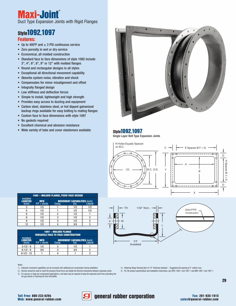
29
general rubber corporationWeb: www.general-rubber.com [email protected] Free: 800-233-6294 Fax: 201-935-1915
Notes:1.) Extension movement capabilities can be increased with additional pre-compression during installation.2.) Anchors should be used to resist the pressure thrust force and isolate the thermal movements between expansion joints.3.) For vacuum or large pre-compressed applications, a set-back may be required to keep the expansion joint from protruding into
the gas stream or touching the flow liner/baffle.
4.) Retaining Rings/ Backing Bars of 1/4" thickness standard. – Suggested bolt spacing at 4" centers max.5.) For full product specifications and installation instructions, see SPEC 1092-1 and 1097-1 and ININ 1092-1 and 1097-1.
Maxi-Joint®
Duct Type Expansion Joints with Rigid Flanges
Style1092,1097Features:• Up to 400ºF and ± 3 PSI continuous service• Zero porosity in wet or dry service• Economical, all molded construction• Standard face to face dimensions of style 1092 include
3", 4", 6", 8", 9" or 12" with molded flanges• Round and rectangular designs in all styles• Exceptional all directional movement capability• Absorbs system noise, vibration and shock• Compensates for minor misalignment and offset• Integrally flanged design• Low stiffness and deflection forces• Simple to install, lightweight and high strength• Provides easy access to ducting and equipment• Carbon steel, stainless steel, or hot dipped galvanized
backup rings available for easy bolting to mating flanges• Custom face to face dimensions with style 1097• No gaskets required• Excellent chemical and abrasion resistance• Wide variety of tube and cover elastomers available Style1092,1097
Single Layer Belt Type Expansion Joints
1097 – MOLDED FLANGEVERSATILE FACE TO FACE CONSTRUCTION
InstalledLENGTHS MFD MOVEMENT CAPABILITIES (inch)
(inch) F/F + (inch) Comp. Ext. Lateral3-1/2 - 6 1/2 2 1/2 16-1/2 - 9 3/4 3 3/4 2
9-1/2 - 12 1 4 1 3
I.D. B.C. O.D.
N Holes Equally Spacedon B.C.
X
B
A
Y
D
D
E Spaces @ F = GC
HS
paces
@J
=K
1/32" Nom.
L
P M
TH
F/F(Installed)
Solid PTFEConstruction
1092 – MOLDED FLANGE, FIXED FACE DESIGNInstalledLENGTHS MFD MOVEMENT CAPABILITIES (inch)
(inch) F/F + (inch) Comp. Ext. Lateral3 1/2 1 1/2 1/24 1/2 1 1/2 1/26 1/2 2 1/2 18 1/2 3 1/2 29 1/2 3 1/2 2
12 1/2 4 3/4 3
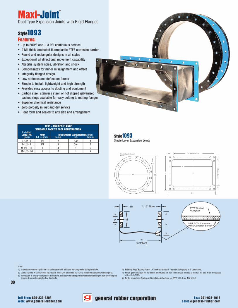
Notes:1.) Extension movement capabilities can be increased with additional pre-compression during installation.2.) Anchors should be used to resist the pressure thrust force and isolate the thermal movements between expansion joints.3.) For vacuum or large pre-compressed applications, a set-back may be required to keep the expansion joint from protruding into
the gas stream or touching the flow liner/baffle.
4.) Retaining Rings/ Backing Bars of 1/4" thickness standard. Suggested bolt spacing at 4" centers max.5.) Flange gaskets suitable for the system temperature and fluid media should be used to ensure a full seal on all fluoroplastic
styles. (Style 1093).6.) For full product specifications and installation instructions, see SPEC 1093-1 and ININ 1093-1.
Maxi-Joint®
Duct Type Expansion Joints with Rigid Flanges
Style1093Features:• Up to 600ºF and ± 3 PSI continuous service• 9 Mil thick laminated fluoroplastic PTFE corrosion barrier• Round and rectangular designs in all styles• Exceptional all directional movement capability• Absorbs system noise, vibration and shock• Compensates for minor misalignment and offset• Integrally flanged design• Low stiffness and deflection forces• Simple to install, lightweight and high strength• Provides easy access to ducting and equipment• Carbon steel, stainless steel, or hot dipped galvanized
backup rings available for easy bolting to mating flanges• Superior chemical resistance• Zero porosity in wet and dry service• Heat form and sealed to any size and arrangement
Style1093Single Layer Expansion Joints
1093 – MOLDED FLANGEVERSATILE FACE TO FACE CONSTRUCTION
InstalledLENGTHS MFD MOVEMENT CAPABILITIES (inch)
(inch) F/F + (inch) Comp. Ext. Lateral3-1/2 - 6 1/2 2 1/2 16-1/2 - 9 3/4 3 3/4 2
9-1/2 - 12 1 4 1 312-1/2 - 16 1 5 1 4
general rubber corporationWeb: www.general-rubber.com [email protected] Free: 800-233-6294 Fax: 201-935-1915
30
1/16" Nom.
F/F(Installed)
9 MILS TH. LaminatedPTFE Corrosion Barrier
PTFE CoatedFiberglass
L
P M
TH
B.C.
I.D. O.D.
N Holes Equally Spaced on B.C.
X
B
A
E Spaces @ F = GC
Y
D
D
HS
paces
@J
=K
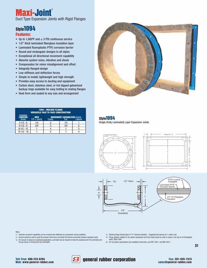
31
general rubber corporationWeb: www.general-rubber.com [email protected] Free: 800-233-6294 Fax: 201-935-1915
P
1/2" Nom.
1/2" TH FiberglassInsulation
PTFE CoatedFiberglass
Laminated PTFECorrosion Barrier
TH
F/F(Installed)
L
B.C.
I.D. O.D.
N Holes Equally Spaced on B.C.
X
B
A
E Spaces @ F = GC
Y
D
D
HS
paces
@J
=K
Notes:1.) Extension movement capabilities can be increased with additional pre-compression during installation.2.) Anchors should be used to resist the pressure thrust force and isolate the thermal movements between expansion joints.3.) For vacuum or large pre-compressed applications, a set-back may be required to keep the expansion joint from protruding into
the gas stream or touching the flow liner/baffle.
4.) Retaining Rings/ Backing Bars of 1/4" thickness standard. – Suggested bolt spacing at 4" centers max.5.) Flange gaskets suitable for the system temperature and fluid media should be used to ensure a full seal on all fluoroplastic
styles. (Style 1094)6.) For full product specifications and installation instructions, see SPEC 1094-1 and ININ 1094-1.
Maxi-Joint®
Duct Type Expansion Joints with Rigid Flanges
Style1094Features:• Up to 1,000ºF and ± 3 PSI continuous service• 1/2" thick laminated fiberglass insulation layer• Laminated fluoroplastic PTFE corrosion barrier• Round and rectangular designs in all styles• Exceptional all directional movement capability• Absorbs system noise, vibration and shock• Compensates for minor misalignment and offset• Integrally flanged design• Low stiffness and deflection forces• Simple to install, lightweight and high strength• Provides easy access to ducting and equipment• Carbon steel, stainless steel, or hot dipped galvanized
backup rings available for easy bolting to mating flanges• Heat form and sealed to any size and arrangement
Style1094Single (Fully Laminated) Layer Expansion Joints
1094 – MOLDED FLANGEVERSATILE FACE TO FACE CONSTRUCTION
InstalledLENGTHS MFD MOVEMENT CAPABILITIES (inch)
(inch) F/F + (inch) Comp. Ext. Lateral3-1/2 - 6 1/2 2 1/2 16-1/2 - 9 3/4 3 3/4 2
9-1/2 - 12 1 4 1 312-1/2 - 16 1 5 1 4
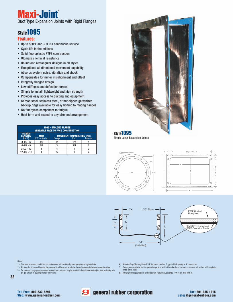
1/16" Nom.
F/F(Installed)
9 MILS TH. LaminatedPTFE Corrosion Barrier
PTFE CoatedFiberglass
L
P M
TH
B.C.
I.D. O.D.
N Holes Equally Spaced on B.C.
X
B
A
E Spaces @ F = GC
Y
D
D
HS
paces
@J
=K
Notes:1.) Extension movement capabilities can be increased with additional pre-compression during installation.2.) Anchors should be used to resist the pressure thrust force and isolate the thermal movements between expansion joints.3.) For vacuum or large pre-compressed applications, a set-back may be required to keep the expansion joint from protruding into
the gas stream or touching the flow liner/baffle.
4.) Retaining Rings/ Backing Bars of 1/4" thickness standard. Suggested bolt spacing at 4" centers max.5.) Flange gaskets suitable for the system temperature and fluid media should be used to ensure a full seal on all fluoroplastic
styles. (Style 1095)6.) For full product specifications and installation instructions, see SPEC 1095-1 and ININ 1095-1.
Maxi-Joint®
Duct Type Expansion Joints with Rigid Flanges
Style1095Features:• Up to 500ºF and ± 3 PSI continuous service• Cycle life in the millions• Solid fluoroplastic PTFE construction• Ultimate chemical resistance• Round and rectangular designs in all styles• Exceptional all directional movement capability• Absorbs system noise, vibration and shock• Compensates for minor misalignment and offset• Integrally flanged design• Low stiffness and deflection forces• Simple to install, lightweight and high strength• Provides easy access to ducting and equipment• Carbon steel, stainless steel, or hot dipped galvanized
backup rings available for easy bolting to mating flanges• No fiberglass component to fatigue• Heat form and sealed to any size and arrangement
Style1095Single Layer Expansion Joints
1095 – MOLDED FLANGEVERSATILE FACE TO FACE CONSTRUCTION
InstalledLENGTHS MFD MOVEMENT CAPABILITIES (inch)
(inch) F/F + (inch) Comp. Ext. Lateral3-1/2 - 6 1/2 2 1/2 16-1/2 - 9 3/4 3 3/4 2
9-1/2 - 12 1 4 1 312-1/2 - 16 1 5 1 4
general rubber corporationWeb: www.general-rubber.com [email protected] Free: 800-233-6294 Fax: 201-935-1915
32
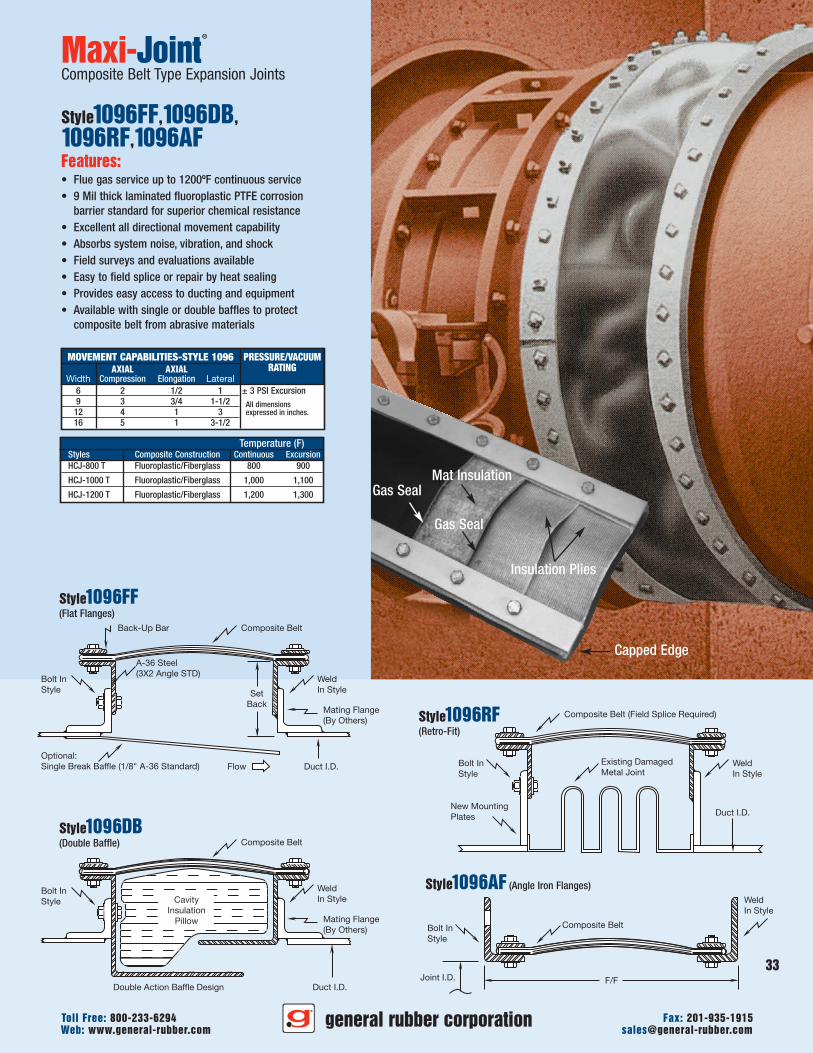
Gas SealMat Insulation
Gas Seal
Insulation Plies
Capped Edge
33
general rubber corporationWeb: www.general-rubber.com [email protected] Free: 800-233-6294 Fax: 201-935-1915
New MountingPlates
Composite Belt (Field Splice Required)
Existing DamagedMetal Joint
Duct I.D.
Back-Up Bar
A-36 Steel(3X2 Angle STD)
Optional:Single Break Baffle (1/8" A-36 Standard)
Bolt InStyle
Composite Belt
Composite Belt
Composite Belt
SetBack
Duct I.D.
WeldIn Style
Bolt InStyle
WeldIn Style
Double Action Baffle Design Duct I.D.Joint I.D. F/F
Flow
CavityInsulation
Pillow
Bolt InStyle
Bolt InStyle
Mating Flange(By Others)
WeldIn Style
Mating Flange(By Others)
WeldIn Style
Maxi-Joint®
Composite Belt Type Expansion Joints
Style1096FF,1096DB,1096RF,1096AFFeatures:• Flue gas service up to 1200ºF continuous service• 9 Mil thick laminated fluoroplastic PTFE corrosion
barrier standard for superior chemical resistance• Excellent all directional movement capability• Absorbs system noise, vibration, and shock• Field surveys and evaluations available• Easy to field splice or repair by heat sealing• Provides easy access to ducting and equipment• Available with single or double baffles to protect
composite belt from abrasive materials
Style1096FF(Flat Flanges)
Style1096DB(Double Baffle)
Style1096RF(Retro-Fit)
Style1096AF (Angle Iron Flanges)
PRESSURE/VACUUMRATING
± 3 PSI ExcursionAll dimensionsexpressed in inches.
MOVEMENT CAPABILITIES-STYLE 1096AXIAL AXIAL
Width Compression Elongation Lateral6 2 1/2 19 3 3/4 1-1/2
12 4 1 316 5 1 3-1/2
Temperature (F)Styles Composite Construction Continuous ExcursionHCJ-800 T Fluoroplastic/Fiberglass 800 900
HCJ-1000 T Fluoroplastic/Fiberglass 1,000 1,100
HCJ-1200 T Fluoroplastic/Fiberglass 1,200 1,300
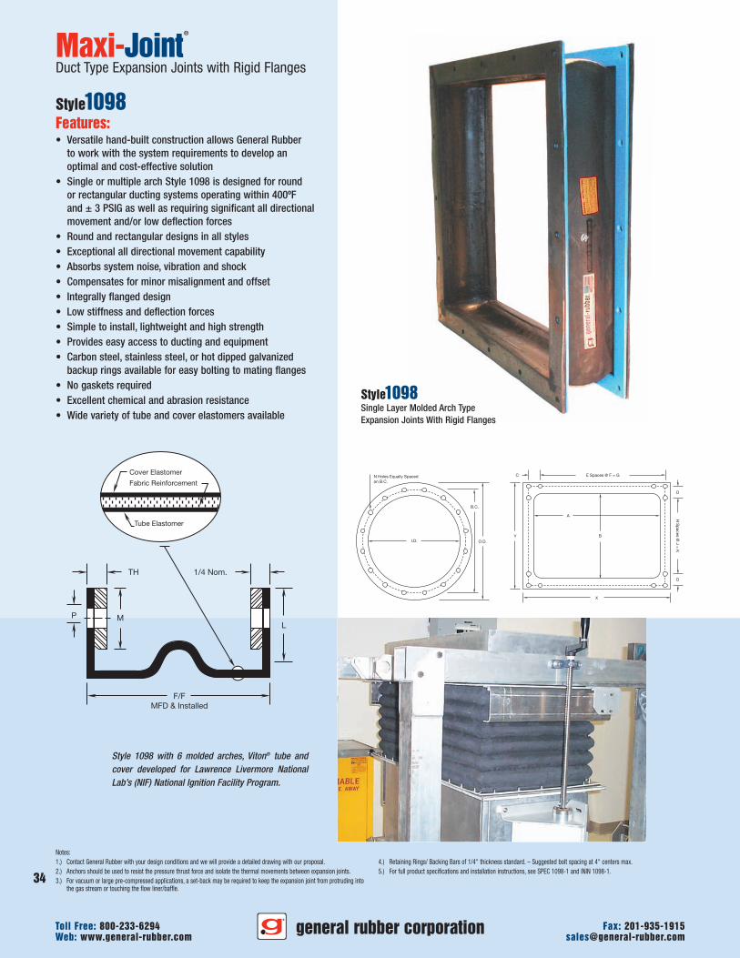
B.C.
I.D. O.D.
N Holes Equally Spaced on B.C.
X
B
A
E Spaces @ F = GC
Y
D
D
HS
paces
@J
=K
Tube Elastomer
Cover Elastomer
Fabric Reinforcement
F/FMFD & Installed
1/4 Nom.
MP
TH
PL
Style 1098 with 6 molded arches, Viton® tube andcover developed for Lawrence Livermore NationalLab’s (NIF) National Ignition Facility Program.
Notes:1.) Contact General Rubber with your design conditions and we will provide a detailed drawing with our proposal.2.) Anchors should be used to resist the pressure thrust force and isolate the thermal movements between expansion joints.3.) For vacuum or large pre-compressed applications, a set-back may be required to keep the expansion joint from protruding into
the gas stream or touching the flow liner/baffle.
4.) Retaining Rings/ Backing Bars of 1/4" thickness standard. – Suggested bolt spacing at 4" centers max.5.) For full product specifications and installation instructions, see SPEC 1098-1 and ININ 1098-1.
Maxi-Joint®
Duct Type Expansion Joints with Rigid Flanges
Style1098Features:• Versatile hand-built construction allows General Rubber
to work with the system requirements to develop anoptimal and cost-effective solution
• Single or multiple arch Style 1098 is designed for roundor rectangular ducting systems operating within 400ºFand ± 3 PSIG as well as requiring significant all directionalmovement and/or low deflection forces
• Round and rectangular designs in all styles• Exceptional all directional movement capability• Absorbs system noise, vibration and shock• Compensates for minor misalignment and offset• Integrally flanged design• Low stiffness and deflection forces• Simple to install, lightweight and high strength• Provides easy access to ducting and equipment• Carbon steel, stainless steel, or hot dipped galvanized
backup rings available for easy bolting to mating flanges• No gaskets required• Excellent chemical and abrasion resistance• Wide variety of tube and cover elastomers available
Style1098Single Layer Molded Arch TypeExpansion Joints With Rigid Flanges
general rubber corporationWeb: www.general-rubber.com [email protected] Free: 800-233-6294 Fax: 201-935-1915
34
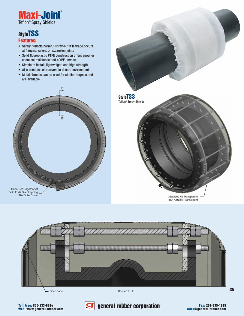
Displayed As TransparentBut Actually Translucent
35
general rubber corporationWeb: www.general-rubber.com [email protected] Free: 800-233-6294 Fax: 201-935-1915
Section E - EFiber Rope
E
E
Rope Tied Together AtBoth Ends Over Lapping
The Solar Cover
Maxi-Joint®
Teflon® Spray Shields
StyleTSSFeatures:• Safely deflects harmful spray-out if leakage occurs
at flanges, valves, or expansion joints• Solid fluoroplastic PTFE construction offers superior
chemical resistance and 400ºF service• Simple to Install, lightweight, and high strength• Also used as solar covers in desert environments• Metal shrouds can be used for similar purpose and
are available
StyleTSSTeflon® Spray Shields
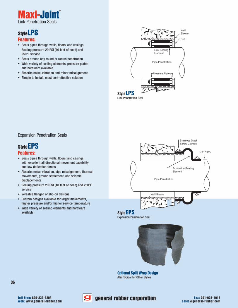
WallSleeve
Bolt
Link SealingElement
Pipe Penetration
Pressure Plates
Stainless Steel Screw Clamps
Wall Sleeve
1/4" Nom.
Expansion SealingElement
Pipe Penetration
Maxi-Joint®
Link Penetration Seals
StyleLP SFeatures:• Seals pipes through walls, floors, and casings
Sealing pressure 20 PSI (40 feet of head) and250ºF service
• Seals around any round or radius penetration• Wide variety of sealing elements, pressure plates
and hardware available• Absorbs noise, vibration and minor misalignment• Simple to install, most cost-effective solution
Expansion Penetration Seals
StyleEP SFeatures:• Seals pipes through walls, floors, and casings
with excellent all directional movement capabilityand low deflection forces
• Absorbs noise, vibration, pipe misalignment, thermalmovements, ground settlement, and seismicdisplacements
• Sealing pressure 20 PSI (40 feet of head) and 250ºFservice
• Versatile flanged or slip-on designs• Custom designs available for larger movements,
higher pressure and/or higher service temperature• Wide variety of sealing elements and hardware
available
StyleLPSLink Penetration Seal
general rubber corporationWeb: www.general-rubber.com [email protected] Free: 800-233-6294 Fax: 201-935-1915
36
StyleEPSExpansion Penetration Seal
Optional Split Wrap DesignAlso Typical for Other Styles
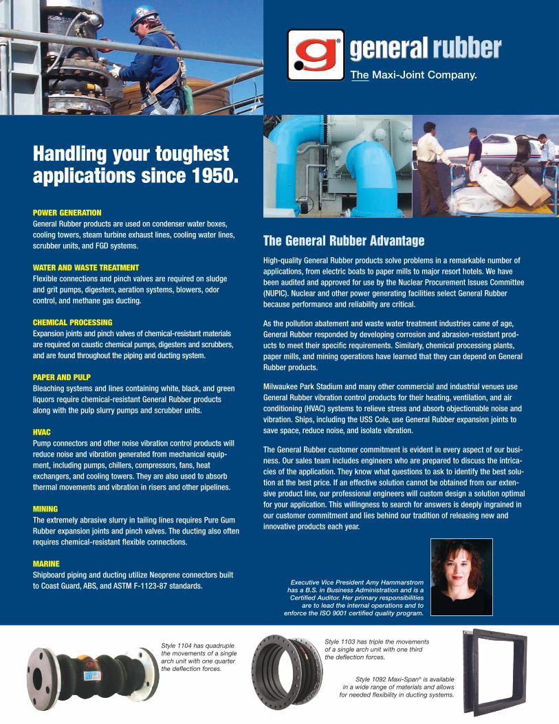
Style 1103 has triple the movementsof a single arch unit with one thirdthe deflection forces.
Style 1104 has quadruplethe movements of a singlearch unit with one quarterthe deflection forces.
Style 1092 Maxi-Span® is availablein a wide range of materials and allowsfor needed flexibility in ducting systems.
The General Rubber AdvantageHigh-quality General Rubber products solve problems in a remarkable number ofapplications, from electric boats to paper mills to major resort hotels. We havebeen audited and approved for use by the Nuclear Procurement Issues Committee(NUPIC). Nuclear and other power generating facilities select General Rubberbecause performance and reliability are critical.
As the pollution abatement and waste water treatment industries came of age,General Rubber responded by developing corrosion and abrasion-resistant prod-ucts to meet their specific requirements. Similarly, chemical processing plants,paper mills, and mining operations have learned that they can depend on GeneralRubber products.
Milwaukee Park Stadium and many other commercial and industrial venues useGeneral Rubber vibration control products for their heating, ventilation, and airconditioning (HVAC) systems to relieve stress and absorb objectionable noise andvibration. Ships, including the USS Cole, use General Rubber expansion joints tosave space, reduce noise, and isolate vibration.
The General Rubber customer commitment is evident in every aspect of our busi-ness. Our sales team includes engineers who are prepared to discuss the intrica-cies of the application. They know what questions to ask to identify the best solu-tion at the best price. If an effective solution cannot be obtained from our exten-sive product line, our professional engineers will custom design a solution optimalfor your application. This willingness to search for answers is deeply ingrained inour customer commitment and lies behind our tradition of releasing new andinnovative products each year.
Handling your toughestapplications since 1950.
POWER GENERATIONGeneral Rubber products are used on condenser water boxes,cooling towers, steam turbine exhaust lines, cooling water lines,scrubber units, and FGD systems.
WATER AND WASTE TREATMENTFlexible connections and pinch valves are required on sludgeand grit pumps, digesters, aeration systems, blowers, odorcontrol, and methane gas ducting.
CHEMICAL PROCESSINGExpansion joints and pinch valves of chemical-resistant materialsare required on caustic chemical pumps, digesters and scrubbers,and are found throughout the piping and ducting system.
PAPER AND PULPBleaching systems and lines containing white, black, and greenliquors require chemical-resistant General Rubber productsalong with the pulp slurry pumps and scrubber units.
HVACPump connectors and other noise vibration control products willreduce noise and vibration generated from mechanical equip-ment, including pumps, chillers, compressors, fans, heatexchangers, and cooling towers. They are also used to absorbthermal movements and vibration in risers and other pipelines.
MININGThe extremely abrasive slurry in tailing lines requires Pure GumRubber expansion joints and pinch valves. The ducting also oftenrequires chemical-resistant flexible connections.
MARINEShipboard piping and ducting utilize Neoprene connectors builtto Coast Guard, ABS, and ASTM F-1123-87 standards. Executive Vice President Amy Hammarstrom
has a B.S. in Business Administration and is aCertified Auditor. Her primary responsibilities
are to lead the internal operations and toenforce the ISO 9001 certified quality program.
The Maxi-Joint Company.
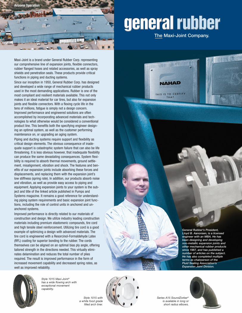
Series A15 SoundZorber®
is available in long orshort radius elbows.
Style 1015 Maxi-Joint®
has a wide flowing arch withexceptional movementcapability.
Style 1015 witha white food grade
filled arch liner.
Arizona Operation
The Maxi-Joint Company.
General Rubber's President,Lloyd B. Aanonsen, is a licensedengineer with an MBA. He hasbeen designing and developingnon-metallic expansion joints andother mechanical rubber productssince 1987, and has published anumber of articles on the subject.He has also completed multipleterms as chairperson of theFluid Sealing Association'sExpansion Joint Division.
Maxi-Joint is a brand under General Rubber Corp. representingour comprehensive line of expansion joints, flexible connectors,rubber flanged hoses and related accessories, as well as sprayshields and penetration seals. These products provide criticalfunctions in piping and ducting systems.Since our inception in 1950, General Rubber Corp. has designedand developed a wide range of mechanical rubber productsused in the most demanding applications. Rubber is one of themost compliant and resilient materials available. This not onlymakes it an ideal material for car tires, but also for expansionjoints and flexible connectors. With a flexing cycle life in thetens of millions, fatigue is simply not a design concern.Improved performance and engineered solutions are oftenaccomplished by incorporating advanced materials and tech-nologies to what otherwise would be considered a conventionalproduct line. This benefits both the specifying engineer design-ing an optimal system, as well as the customer performingmaintenance on, or upgrading an aging system.Piping and ducting systems require support and flexibility ascritical design elements. The obvious consequence of inade-quate support is catastrophic system failure that can also be lifethreatening. It is less obvious however, that inadequate flexibilitycan produce the same devastating consequences. System flexi-bility is required to absorb thermal movements, ground settle-ment, misalignment, vibration and shock. The features and ben-efits of our expansion joints include absorbing these forces anddisplacements, and replacing them with the expansion joint’slow stiffness (spring rate). In addition, our products absorb noiseand vibration, as well as provide easy access to piping andequipment. Applying expansion joints to your system is the sub-ject and title of the linked article published in Pumps andSystems magazine. It remains a good reference for understand-ing piping system requirements and basic expansion joint func-tions, including the role of control units in anchored and un-anchored systems.Improved performance is directly related to our materials ofconstruction and design. We utilize industry leading constructionmaterials including premium elastomeric compounds, tire cordand high tensile steel reinforcement. Utilizing tire cord is a goodexample of optimizing a design with advanced materials. Thetire cord is engineered with a Resorcinol-Formaldehyde Latex(RFL) coating for superior bonding to the rubber. The cordsthemselves can be aligned on an optimal bias ply angle, offeringtailored strength in the directions needed. This virtually elimi-nates delamination and reduces the total number of pliesrequired. The result is improved performance in the form ofincreased movement capability and decreased spring rates, aswell as improved reliability.
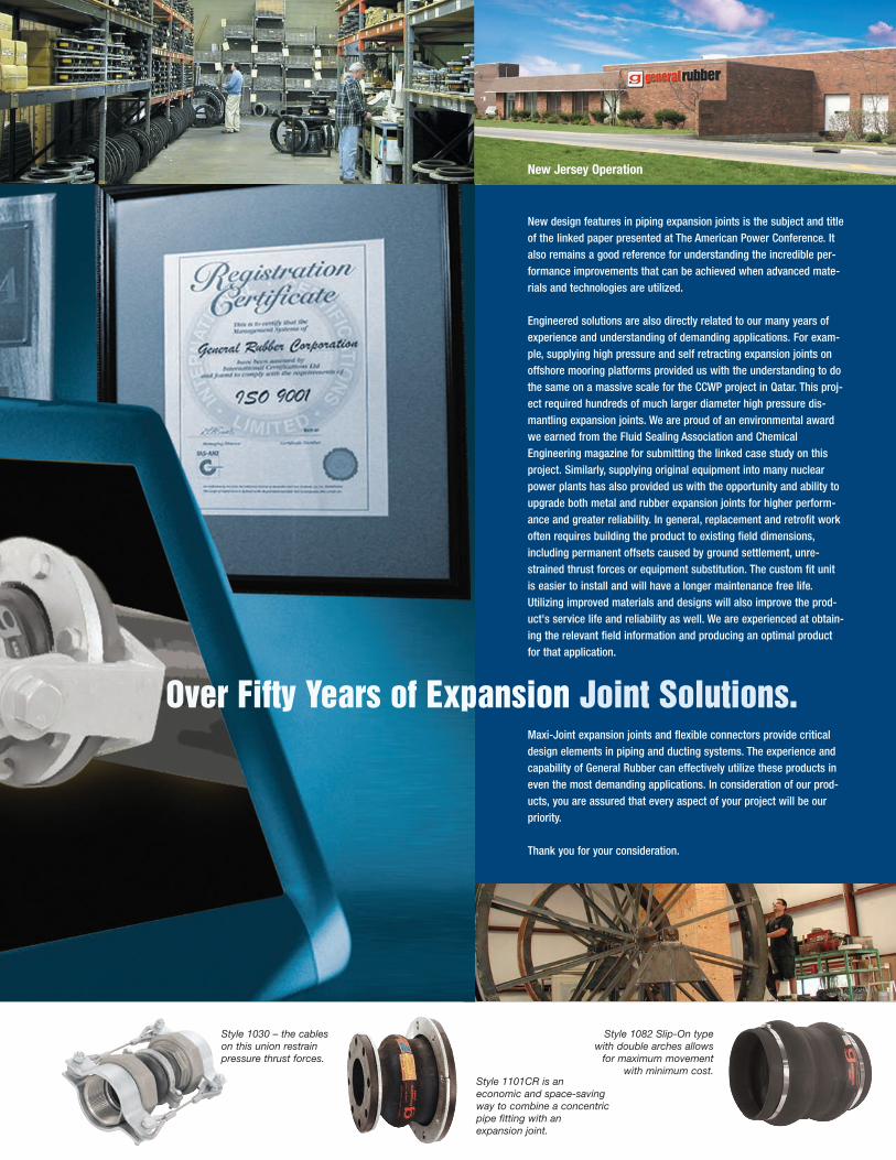
Style 1101CR is aneconomic and space-savingway to combine a concentricpipe fitting with anexpansion joint.
Style 1082 Slip-On typewith double arches allowsfor maximum movement
with minimum cost.
New design features in piping expansion joints is the subject and titleof the linked paper presented at The American Power Conference. Italso remains a good reference for understanding the incredible per-formance improvements that can be achieved when advanced mate-rials and technologies are utilized.
Engineered solutions are also directly related to our many years ofexperience and understanding of demanding applications. For exam-ple, supplying high pressure and self retracting expansion joints onoffshore mooring platforms provided us with the understanding to dothe same on a massive scale for the CCWP project in Qatar. This proj-ect required hundreds of much larger diameter high pressure dis-mantling expansion joints. We are proud of an environmental awardwe earned from the Fluid Sealing Association and ChemicalEngineering magazine for submitting the linked case study on thisproject. Similarly, supplying original equipment into many nuclearpower plants has also provided us with the opportunity and ability toupgrade both metal and rubber expansion joints for higher perform-ance and greater reliability. In general, replacement and retrofit workoften requires building the product to existing field dimensions,including permanent offsets caused by ground settlement, unre-strained thrust forces or equipment substitution. The custom fit unitis easier to install and will have a longer maintenance free life.Utilizing improved materials and designs will also improve the prod-uct's service life and reliability as well. We are experienced at obtain-ing the relevant field information and producing an optimal productfor that application.
Maxi-Joint expansion joints and flexible connectors provide criticaldesign elements in piping and ducting systems. The experience andcapability of General Rubber can effectively utilize these products ineven the most demanding applications. In consideration of our prod-ucts, you are assured that every aspect of your project will be ourpriority.
Thank you for your consideration.
Style 1030 – the cableson this union restrainpressure thrust forces.
New Jersey Operation
Over Fifty Years of Expansion Joint Solutions.
The information presented in this catalog is
provided in good faith. General Rubber Corp.
reserves the right to modify or improve its design
specifications without notice and does not imply
any guarantee or warranty for any of its products
from reliance upon the information contained
herein. For specific application recommendations,
consult General Rubber Corp. Failure to properly
select products could result in property damage
and/or serious personal injury. All orders are
subject to final acceptance by General Rubber Corp.
Viton®, Hypalon®, Teflon®, and Kevlar® are regis-
tered trademarks of DuPont Performance
Elastomers.
general rubber corporationSales and Engineering Headquarters850 Washington AvenueCarlstadt, NJ 07072
Phone: Toll Free:201-935-1900 800-233-6294Fax:201-935-1915
www.general-rubber.com
© 2011, General Rubber Corporation.
Printed in U.S.A.
GC-561 GR-561/05/11/5M
RECYCLABLEPAPER