the middlebury sand hill bridge gregory s....
TRANSCRIPT
Goodrich and Kretsch 2016 PCI/NBC
THE MIDDLEBURY SAND HILL BRIDGE
Gregory S. Goodrich, PE Vanasse Hangen Brustlin, Bedford, NH Kristopher G. Kretsch, PE Vanasse Hangen Brustlin, Watertown, MA
ABSTRACT
The historic Sand Hill Bridge, a closed spandrel arch spanning the gorge over the Middlebury River in Middlebury, Vermont, was originally constructed in 1924 and in need of replacement. The new bridge, replicating the original, was anything but typical, consisting of a precast/prestressed NEXT Beam bridge spanning a new 48-foot diameter precast arch, founded on full-height precast abutments on precast spread footings. To give the appearance of the original historic arch, giant precast architectural panels were erected to “close off” the airspace between the NEXT Beam superstructure and the new precast arch. The new bridge was constructed on the existing Vermont Route 125 alignment in 45 days utilizing a full road closure and Accelerated Bridge Construction (ABC) techniques. All 53 precast elements of the bridge were erected in a total of 9 days. The precast was fabricated by a locally owned plant in the Town of Middlebury and the project was administered by the Vermont Agency of Transportation’s newly formed Accelerated Bridge Program. The Contractor was able to successfully construct this intricate bridge through closely coordinated and choreographed execution. This project was a major success for the State of Vermont, and was also supported and celebrated by the Town of Middlebury. The new bridge is a standing testament to what can be accomplished through innovation, dedication, and commitment by all parties involved.
Keywords: Accelerated Bridge Construction, Historic, Arch, NEXT Beam

Goodrich and Kretsch 2016 PCI/NBC
- 1 -
INTRODUCTION In 1984 the Vermont Agency of Transportation (VTrans) originally set out to replace the Sand Hill Bridge, a historic single span closed spandrel arch concrete bridge, constructed in 1924, in Middlebury, Vermont. It wasn’t until June 2014 that the new bridge was completed, due in large part to the implementation of Accelerated Bridge Construction (ABC), the development of precast/prestressed concrete bridge components, and the spirit of collaboration between the Towns of Middlebury, Ripton, and VTrans. The new bridge, a single span 62-foot 6-inch Northeast Extreme Tee (NEXT) beam bridge on full-height precast concrete abutments, spanning over a 48-foot diameter precast concrete arch, was constructed in less than 45 days using a complete roadway closure. This paper will take a closer look at the reasons, details, and careful planning that made this project a success not only for the Vermont Agency of Transportation, but for the residents of the Town of Middlebury and surrounding communities. PROJECT CHALLENGES The existing 1924 single span closed spandrel arch concrete bridge was in need of replacement. The curb-to-curb width of the bridge was 20-feet 6-inches, and it was located in the middle of a sharp reverse curve on the steep and scenic Vermont Route 125, at the base of Breadloaf Mountain at over a 7.5 percent grade. The bridge spans a 42-foot rock gorge carrying the Middlebury River (see Figure 1). The site also serves as a popular recreational swimming hole, and was also home to the archaeologically sensitive site known as the East Middlebury Iron Works site. This archaeological resource contains the remnants of the early 1830’s iron works, which was the last operating iron works in Vermont, and is thought to be the best preserved example of this type of iron works in the state.
Figure 1: Existing Bridge

Goodrich and Kretsch 2016 PCI/NBC
- 2 -
This project is located in the town of Middlebury, Vermont, a popular tourist destination in the winter, summer, and fall. The bridge is in a rural setting on the east side of town, with the shortest available state detour route being approximately 30 miles long. Due to the immediately adjacent archaeological site, the gorge, and the recreational resources, constructing an off-line temporary bridge was not feasible. Due to the economic impacts to local businesses and residents, closing the roadway down for an extended period of time to replace the bridge was not desirable. In the 1990s and early 2000s VTrans was moving the project forward with marginal success. The initial concept was to replace the bridge using an extended closure and flattening out the curves on each approach, thereby impacting the gorge, the archaeological site, and the swimming hole. The roadway was also to be widened, thereby removing several trees. Initial plans called for the bridge to be constructed over a 2-year period using a temporary bridge that would have impacted the gorge, the archaeologically sensitive site, and the swimming hole even further. This was met with stiff resistance by the Town, residents, and local businesses and the project was temporarily shelved while they searched a solution. In 2011, VTrans once again revived the project and brought on a design consultant. In early September 2011, Tropical Storm Irene slammed into Vermont, dropping over 11 inches of rain, decimating hundreds state and local roadways, bridges, and other public and private infrastructure. This bridge survived untouched, however, the project was once again temporarily on-hold until the natural disaster effort wound down. This historic tropical storm gave rise to a new mindset within the Agency and several towns and residents. Infrastructure was replaced at a rapid rate using techniques and contracting means and methods that were largely unused in the state prior to that time. Bridge replacements were happening at a much faster pace, and contractors were more accustomed to working with compressed schedules and using accelerated bridge construction techniques. Municipalities and residents alike had taken notice, and on the heels of the storm, they were even more sensitive to closing down roadways for extended periods of time as communities struggled to recover economically. In 2012, with the vast project history in focus, and with the storm still fresh in everyone’s mind, the goals of this project became clear, and the challenges were well defined: provide a replacement bridge that creates minimal impacts to archaeologically sensitive areas and recreational resources; preserve the look and feel of the existing roadway, with improved safety for motorists and pedestrians; conserve the historic context of the original bridge and the gorge below while minimizing impacts to local businesses and residents; and gain the support of the town and surrounding communities.

Goodrich and Kretsch 2016 PCI/NBC
- 3 -
PROPOSED BRIDGE When the Agency initially engaged their design consultant, the revised conceptual alignment had already been developed, however, the final bridge type was still undetermined. The Agency had already established the new rail-to-rail width of the bridge at 34 feet, an improvement of over 13 feet in width compared to the existing bridge, including two 11-foot travel lanes, a 5-foot sidewalk with an adjacent 3-foot shoulder on the west side of the bridge, and a 4-foot shoulder on the east side. The roadway alignment had been shifted approximately 6 feet to the east in order to keep the west bridge fascia as close as possible to the existing bridge fascia. This would minimize impacts to the recreational swimming hole and the archaeological site on the west side of the bridge. With the proposed alignment approximating the existing one, the Town was satisfied that the new project would not drastically change the characteristics of the existing roadway. The more pressing issue was how to replace the bridge with one that would look similar to the existing, but would not bear on the rock directly adjacent to the gorge due to the weathered nature of the rock and concerns for the long-term durability and competency of the rock. Several options were considered, including: a long-span precast arch founded well beyond the edges of the gorge; a traditional bridge with haunched girders; and a traditional bridge with an architectural façade that simulates an arch. Due to the span length required to properly locate the footings, and the limited allowable profile raise on the approaches to minimize side slope impacts, the span-to-depth ratio of an arch would have a very elliptical aesthetic whereas the existing bridge was a perfect semi-circle. When presented to the town and public, there was little support for a bridge that did not closely resemble the existing bridge. The same was also true when coordinating with the State Historic Preservation Officer, who also preferred a true semi-circular arch. Structurally, the ideal bridge span would be in the 60 to 65-foot range, compared to the existing arch bridge which spanned 42 feet. With that consideration in mind, and the span-to-depth ratios relatively fixed, the focus was on developing a traditional bridge concept, and adapting an arch form to it. The concept that was proposed to the Agency and the Town was a 62-foot 6-inch span NEXT Beam bridge on full-height abutments. This bridge would span over a new 48-foot diameter concrete arch that would be completely independent of the bridge above it, thereby not imparting any live load onto the arch. By spanning over the arch, it only had to support its own dead load. Placing the light dead load of the arch directly adjacent to the gorge was deemed to be acceptable by the geotechnical engineer. Installing an architectural façade at the bridge fascia closed up the air gap between the bridge superstructure and the concrete arch below (see Figures 2 and 3). The finished product very closely resembled the existing arch bridge.

Goodrich and Kretsch 2016 PCI/NBC
- 4 -
Figure 2: Early Conceptual Bridge Section
Figure 3: Early Conceptual Bridge Elevation With the geometric concept in-place, the next challenge was to design and detail the bridge in a way that it could be constructed within a very aggressive schedule. Through coordination with the Town, a 45 day road closure was negotiated. Vermont Route 125 is a primary east-west link between Interstate 89 on the east side of Vermont and the Town of Middlebury. The summer and fall are prime tourist seasons for Vermont, and are vital to the local economy. In the winter, Vermont Route 125 connects the Middlebury Snow Bowl, a popular nearby ski mountain operated by the College of Middlebury, to the Town and surrounding area. With these seasonal constraints, the window of opportunity to close the roadway was from mid-April to the end of May, for approximately 45 days.
Goodrich and Kretsch 2016 PCI/NBC
- 5 -
This particular site posed several constructability challenges. Due to the mountainous topography of the immediate area, the narrow characteristics of the existing roadway, the presence of the rock gorge, and the adjacent archaeologically sensitive site, the construction site was very restricted. Project permits required barrier fence to be placed around the East Middlebury Iron Works site to protect it from construction activities. As a result of these restrictions, there was very little room for construction staging or machinery in and around the site prior to or after the roadway closure. Furthermore, the presence of shallow rock formations on the south approach meant that over 300 cubic yards of solid rock had to be excavated in order to prepare the site to receive the new foundations. While the surface of the rock along the edge of the gorge was weathered and relatively soft, the rock core samples taken near the proposed foundation locations indicated that the rock was very dense with a compressive strength of 50,000 psi. The geologist indicated that this rock would be very difficult to efficiently excavate by mechanical means, and therefore suggested a blasting program to fracture the rock to facilitate excavation. In order to construct this style of bridge in an accelerated manner, given the relative complexity of the bridge, the site restrictions, and geological features, it was evident that the only way to complete this structure would be to construct it out of prefabricated elements to the extent possible. This would reduce the amount of on-site forming, casting, and curing required. The bridge was designed to include precast footings, abutment stems, wingwalls, NEXT beams, approach slabs, arch panels, and architectural face panels to close in the arch. CONTRACT SPECIFICATIONS Throughout the design process, VTrans was engaged to examine the project from many angles with the consultant. The Accelerated Bridge Program Unit, which managed the delivery of the project through all phases, coordinated directly with other units in the Agency, and the design consultant, as needed. Throughout the project development process, the VTrans Project Manager facilitated several meetings to discuss constructability of the project. Special attention was given by the Geotechnical Unit to the geological conditions at the site including the gorge and the rock on which the bridge would be founded. Several members of the Agency’s Construction Unit also evaluated the project. Detailed construction schedules were developed by the consultant to demonstrate the intended sequence of construction and anticipated timeframes for the major tasks. Once the design plans were completed, the designers worked with the Agency’s Contracts Section to develop the appropriate administrative specifications and requirements, including an incentive/disincentive clause, a critical path method (CPM) construction schedule specification, and required public outreach.

Goodrich and Kretsch 2016 PCI/NBC
- 6 -
For this particular project, a progressive incentive/disincentive (I/D) clause was used to incentivize the contractor to not only open the roadway to traffic on-time, or early, but the provision was also written to encourage the contractor to begin the roadway closure early, and therefore finish earlier in the year. This was in order to limit impacts to the local businesses during the prime tourism months. This was accomplished by designating three available bridge closure periods (BCPs), allowing possible roadway closures from April 19th through June 2nd, April 16th through June 9th, or May 3rd through June 16th. The lump-sum compensation for finishing the work by the end of each BCP was $88,000, $56,000, and $24,000 respectively, thereby providing more incentive to the Contractor to start the work earlier in the construction season. In addition to the lump-sum compensation as defined above, the contract was also laden with additional incentive to finish early, including a $32,000 per day incentive, up to a total incentive compensation payout of $120,000 (including the lump sum payment as defined above). The disincentive for going beyond the specified bridge closure period was set at $32,000 per day, with no maximum on the disincentive amount. Any assessed disincentive was separate from, and would be imposed in addition to, liquidated damages as allowed by the Contract. The project specifications also required the Contractor to submit a Critical Path Method (CPM) schedule within 30 days of the award of the Contract. This proved to be very helpful not only to the Agency in understanding the Contractor’s proposed sequence of construction and critical path milestones, it also helped the Contractor get fully engaged in the project early on and demonstrated the Contractor’s knowledge of the project. It was this process that opened the door to effective communication and coordination for the project early on. There were several iterations, questions, and back-and-forth communication about how the project was going to be built, and often related the Contractor’s understanding of the sequence and duration of events back to the specifications and other requirements of the projects, specifically cure times for grout prior to tasks like backfilling or setting the next sequence of pieces. A blasting plan was also required as part of the early coordination effort. Evaluating the blasting plan well in advance of the bridge closure was vital as the blasting schedule and method of blasting had a pronounced impact activities which were also scheduled near the start of the closure period. Rock blasting was the first task to take place once the road was closed, shortly followed by bridge demolition, rock excavation, and footing preparation. The rock excavation was one of the biggest unknowns, due to the density of the rock. Excavation took approximately three days to complete. DESIGN CONSIDERATIONS There were several key design issues to work through during the design process. Once the basic requirement was established, the design had to accommodate the site characteristics. These included, but weren’t limited to: horizontal roadway alignment

Goodrich and Kretsch 2016 PCI/NBC
- 7 -
and superelevation, gorge characteristics and rock profiles, utility accommodation, and prefabrication details. Horizontal Roadway Alignment and Superelevation The bridge is located in a reverse curve. At the early stages of final design, it was recognized that, due to the tight radius curves on each approach, a significant superelevation would be required (see Figure 4). In anticipation of simplifying design details, the final bridge location, horizontal curves, and superelevation transitions were all adjusted slightly so that the point of superelevation inflection would occur at the exact mid-point of the bridge. This proved to be a very important element in design as it simplified the detailing significantly as it created geometric symmetry. Since the preferred superstructure type was the prestressed concrete NEXT beam, it was recognized that the beams could not be detailed to accommodate the reverse superelevation simply by stepping the bridge seats or through rotating the beams about the centerline of the bridge. To simplify construction and detailing, they were placed on a 0 percent cross slope, and were positioned to match the longitudinal grade of the roadway. In order to compensate for the change in superelevation, there were a few options considered: build up the superelevation using variable depth asphalt, or provide a variable depth cast-in-place concrete topping slab finished with a 3 inch constant depth asphalt overlay and membrane. There were benefits and drawbacks to each alternative. For the variable depth asphalt option the primary concern was that, with over 10” of maximum pavement depth at opposite corners of the bridge, the pavement would rut over time. This would not be a concern with the concrete topping slab, however, placing a cast-in-place slab would take longer to form, place reinforcing steel, cast, and cure in the field during the bridge closure period. With the concrete topping slab, the final 3 inches of pavement would be constant over the bridge, simplifying paving operations. This would also be more resilient to constantly turning and braking truck traffic coming down off of the mountain. It was determined that the schedule would allow for proper placement and curing time, therefore the concrete topping slab alternative was chosen for design and detailing in the final plans.

Goodrich and Kretsch 2016 PCI/NBC
- 8 -
Figure 4: Bridge Plan and Elevation – Note Horizontal Alignment and Profile
Gorge Characteristics and Rock Profiles The edges of the gorge had to be preserved to the extent possible. This was the mandate of the Town of Middlebury and its residents. During public meetings, there was significant concern that the construction would drastically alter the appearance and aesthetic of the gorge. Removing too much rock, or damaging the walls of the gorge would not be allowable. In order to preserve the gorge, limiting the amount of rock removal, and therefore maintaining an arch footing elevation similar to that of the existing bridge, was a primary focus. Geometrically, the arch had to be semi-circular, not elliptical, and the arch also had to be founded close to the edge of the gorge, but far enough back so that it could be placed on sound rock. This brought the arch from the existing 42-foot diameter to a new size of 48-feet in diameter, placing the footings slightly behind the existing arch, and slightly lower than the existing in order to remove some of the weathered rock and to provide a constant elevation base. With a larger diameter, the other concern was providing enough clearance to the superstructure that would span over the arch. The amount of profile raise was limited to approximately 3 feet in order to minimize the limits of construction and impacts on the approaches. The rock profile on the south approach rose sharply moving away from the gorge. This required line drilling and blasting in order to efficiently remove the extremely dense quartzite. Borings were taken both within the footprint of the existing bridge

Goodrich and Kretsch 2016 PCI/NBC
- 9 -
and also on the side slopes where possible. Rock outcroppings were surveyed to supplement the rock core and boring data. This gave a relatively accurate representation of the subsurface conditions, and also affected the design and layout of the abutments and wings. Since both abutments were to be founded on rock, and to facilitate rapid construction the footings were to be precast concrete. It was also necessary to incorporate a cast-in-place unreinforced concrete sub-footing. This varied in depth in order to allow for sufficient allowance for rock elevation variation in construction. Utility Accommodation The existing bridge carried a secondary water line for the residents of East Middlebury. This line served as a back-up to the primary line which was further to the west of the project limits. Since this waterline was a secondary line, it was possible to take it completely out of service during construction, which was very beneficial. In design, however, the bridge had to be detailed to accommodate the new line. With limited clearance between the NEXT beam superstructure and the crown of the new concrete arch, careful attention had to be paid to where and how the waterline would be carried on the bridge. The logical place to carry the waterline was in between the webs of the NEXT beams. This only left approximately 1 foot of clearance between the bottom of the waterline and the top of the arch at mid-span. Also, due to the fact that the space between the superstructure and the arch would be closed off by precast concrete face panels, it would be necessary to install the new waterline prior to installing the face panels, which put the waterline construction in the critical path. In order to mitigate scheduling issues, the waterline construction was carried in the contract, so that the Contractor could either do the work themselves or contract with a sub-consultant that would be directly under their control, instead of the Town engaging a waterline contractor separately to complete the utility work. This made the East Middlebury Fire District (the owners of the waterline) a party to the bridge contract, which was handled by a separate agreement between VTrans and the East Middlebury Fire District. Prefabrication Details All of the major structural components of the bridge were manufactured out of precast concrete in order to facilitate rapid construction. Precast components included: footings, abutment stems, wingwalls, NEXT beams, approach slabs, the arch, and architectural face panels. Precast footings were detailed with leveling jacks on each side of the footing, spaced at 4 feet along the length of the footing, with grout ports spaced at 2 feet along the length of the footing. Footing segments were joined using 9-inch minimum width closure pour joints, hooking the reinforcing steel in the joint to provide sufficient continuity. The precast footing sections were required to support the dead weight of
Goodrich and Kretsch 2016 PCI/NBC
- 10 -
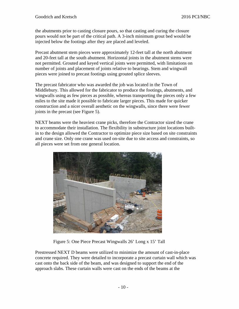
the abutments prior to casting closure pours, so that casting and curing the closure pours would not be part of the critical path. A 3-inch minimum grout bed would be injected below the footings after they are placed and leveled. Precast abutment stem pieces were approximately 12-feet tall at the north abutment and 20-feet tall at the south abutment. Horizontal joints in the abutment stems were not permitted. Grouted and keyed vertical joints were permitted, with limitations on number of joints and placement of joints relative to bearings. Stem and wingwall pieces were joined to precast footings using grouted splice sleeves. The precast fabricator who was awarded the job was located in the Town of Middlebury. This allowed for the fabricator to produce the footings, abutments, and wingwalls using as few pieces as possible, whereas transporting the pieces only a few miles to the site made it possible to fabricate larger pieces. This made for quicker construction and a nicer overall aesthetic on the wingwalls, since there were fewer joints in the precast (see Figure 5). NEXT beams were the heaviest crane picks, therefore the Contractor sized the crane to accommodate their installation. The flexibility in substructure joint locations built-in to the design allowed the Contractor to optimize piece size based on site constraints and crane size. Only one crane was used on-site due to site access and constraints, so all pieces were set from one general location.
Figure 5: One Piece Precast Wingwalls 26’ Long x 15’ Tall
Prestressed NEXT D beams were utilized to minimize the amount of cast-in-place concrete required. They were detailed to incorporate a precast curtain wall which was cast onto the back side of the beam, and was designed to support the end of the approach slabs. These curtain walls were cast on the ends of the beams at the

Goodrich and Kretsch 2016 PCI/NBC
- 11 -
fabrication plant in order to eliminate the need for casting backwalls in the field. This detail also provided a “jointless” bridge, as the curtain wall was designed to extend below the top of the bridge seat, thereby eliminating the need for a traditional bridge joint (see Figure 6). In effect, once the beams were set on the bridge seats, the beam closure pours could be completed, the abutments backfilled, and the precast approach slabs set.
Figure 6: Abutments and NEXT Beams – Note Precast Curtain Wall
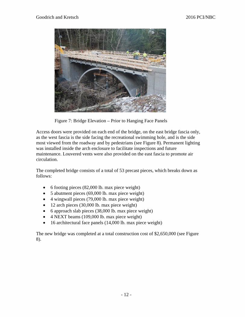
The arch was conceptually detailed in the plans, such that the Contractor could pursue a few viable precast arch alternatives. There were a few precast arch vendors who had products that could be relatively easily adapted to meet the needs of the project. In the end, a proprietary arch system was not utilized. The local fabricator who built the project designed and detailed the arch themselves, and constructed custom formwork for the arch. The arch was constructed using two “leaves” per arch segment to create the finished shape. A cast-in-place “crown beam” was utilized at the top of the arch to lock all of the precast pieces together. This “crown beam” concept was detailed in the contract plans, and was ultimately carried forward in the final design of the arch. Architectural face panels were detailed to hang off of a galvanized steel box support beam. A steel box shape was selected due to torsional and weak axis rigidity. Face panels were hung off of the support beam so that the dead load would not be supported by the superstructure, thereby not subjecting the panels to live load deflections. The support beam was supported by the abutments, which is independent from the precast arch itself (see Figure 7). The panels hang in front of the arch, thereby concealing the precast arch in elevation. This also serves to keep the arch panels from imparting any vertical load on the arch itself.
Goodrich and Kretsch 2016 PCI/NBC
- 12 -
Figure 7: Bridge Elevation – Prior to Hanging Face Panels
Access doors were provided on each end of the bridge, on the east bridge fascia only, as the west fascia is the side facing the recreational swimming hole, and is the side most viewed from the roadway and by pedestrians (see Figure 8). Permanent lighting was installed inside the arch enclosure to facilitate inspections and future maintenance. Louvered vents were also provided on the east fascia to promote air circulation. The completed bridge consists of a total of 53 precast pieces, which breaks down as follows:
6 footing pieces (82,000 lb. max piece weight) 5 abutment pieces (69,000 lb. max piece weight) 4 wingwall pieces (79,000 lb. max piece weight) 12 arch pieces (30,000 lb. max piece weight) 6 approach slab pieces (38,000 lb. max piece weight) 4 NEXT beams (109,000 lb. max piece weight) 16 architectural face panels (14,000 lb. max piece weight)
The new bridge was completed at a total construction cost of $2,650,000 (see Figure 8).

Goodrich and Kretsch 2016 PCI/NBC
- 13 -
Figure 8: Completed Bridge
CONCLUSION The new Sand Hill Bridge was open to traffic in less than 45 days. The Contractor finished early enough to receive the full incentive, and the bridge opened to traffic on June 1, 2014. The 53 precast pieces were erected in just nine days, allowing sufficient time for demolition of the existing bridge, rock removal, construction of the new waterline, backfilling the structure, approach roadway work, construction of the cast-in-place topping slab, sidewalk, and concrete parapets, drainage and approach pavement all within the 45 day bridge closure period. The Town celebrated the achievement with a bridge opening ceremony, a small parade, music, and a reception at a nearby inn. The new bridge was a resounding success, and is a standing testament to what can be accomplished through innovation, dedication, and commitment by all parties involved.