the minerals, metals & materials society welcomes … me founded 1871 the minerals, metals &...
TRANSCRIPT

AI ME
FOUNDED 1871
The Minerals, Metals & Materials Society welcomes you to the
TECHNICAL PROGRAM for the 133rd TMS Annual Meeting & Exhibition,
to be held March 14–18, 2004, in Charlotte, North Carolina.
This document comprises
TUESDAY’STECHNICAL PROGRAMIncluding fully text-searchablepaper titles, abstracts, andauthor names with affi liations
See you in Charlotte!
For your convenience, we have also included details on ■ Meeting Activities and Registration
■ Conference Proceedings
■ Our Exhibition
■ TMS Membership
■ Additional On-line Resources that You May Utilize
All designed to helpyou prepare for—and optimally benefi t from—one of the world’s premiermetals and materials events.
PHOTO COURTESY OF DROSS ENGINEERING: 2M3 CAPACITY FURNACE
PHOTO COURTESY OF LIGHT METALS CENTRE, THE UNIVERSITY OF AUCKLAND
PHOTO COURTESY OF SOLIOS GROUP
http://www.tms.org/AnnualMeeting.html

Customized to meet your unique needs and now upgraded to provide faster service and easier navigation, the On-Line TMS Document Center provides detailed information and on-line purchasing opportunities for TMS proceedings volumes, textbooks, journals, software programs, video series, and reports. If you need information, you’ve got to try the new TMS Document Center.
Check out these great new features:
Find, Select, and Check Out the Products You Want FAST The new TMS Document Center provides easier navigation and faster service for an overall improved shopping experience.
Sample Articles Before You Buy Not sure if a particular article is the one you need? Click on the PDF icon to view the fi rst page of the article and know that you will be satisfi ed with your purchase.
TMS Members: View JOM On-Line Free of Charge TMS members can view the journal for free through the new TMS Document Center. Simply log in and articles from past and current issues are instantly at your fi ngertips to browse, read, and print out, free of charge!
Purchase Download Suites Purchase downloads in sets of 10, 25, 50, or 100, and use them to download any fi les in the TMS Document Center (for less than it would cost to download that many papers individually!). Download suites can be used all at once, over a series of visits to the site, or to create your own custom publication.
Create Your Own Custom Publication Gather individual papers and articles from TMS proceedings volumes, JOM, Journal of Electronic Materials, and Metallurgical and Materials Transactions A and B to create a one-of-a-kind publication that meets your needs. TMS will compile them in either a softcover book or on a CD-ROM—it’s your choice.
Coming in 2004: TMS Letters TMS Letters is a peer-reviewed, on-line-only journal featuring technical updates of hitherto unpublished research presented at TMS meetings. Available free-of-charge to TMS members (and by subscription to nonmembers), the journal comprises two-page technical updates, including text and graphics. Visit the TMS Document Center for additional information about TMS Letters!
See it for yourself!Visit the new TMS Document Center today.
http://doc.tms.orghttp://doc.tms.org
The Improved Web Resourcefor Every TMS Publication…
The New On-LineTMS Document CenterThe New On-LineTMS Document Center

During the week of March 14–18, the 2004 TMS Annual Meeting & Exhibition will host approximately 4,000 science and engineering professionals, representing more than 70 different countries. They are convening at the Charlotte Convention Center to attend a fi eld-spanning array of metals and materials symposia containing more than 200 sessions and 1,900 individual technical presentations.
AN INTERNATIONAL EVENT IN SCIENCE AND ENGINEERING
This year's meeting will feature programming by
■ TMS Electronic, Magnetic & Photonic Materials Division■ TMS Extraction & Processing Division■ TMS Light Metals Division■ TMS Materials Processing & Manufacturing Division■ TMS Structural Materials Division■ TMS Education Committee■ TMS Young Leaders Committee■ ASM International’s Materials Science Critical
Technologies Sector■ International Titanium Association■ International Magnesium Association■ National Science Foundation■ TMS Public & Governmental Affairs Committee
In addition to the technical programming featured on the following pages, attendees will have the opportunity to
■ Tour the Exhibition of more than 160 Companies Displaying New Products and Services
■ Attend Special Lectures and Tutorials
■ Participate in Short Courses on Metal Matrix Composites, Introduction to Nanomanufacturing and Nanotechnology, Technology Transfer Seminar, Smelter Grade Alumina from the Smelting Perspective and Computational Modelling for the Materials Professional
■ Enjoy Special Luncheons, Dinners, and Social Functions, including events honoring Didier de Fontaine, R.J. Arsenault, A.L. Roytburd and Roger D. Doherty
■ Network Extensively
■ Experience the Charm and Amenities of Charlotte
Extensive details about these and all conference-related activities can be found on the 2004 TMS Annual Meeting Web Site.
Registration is easy.
Just complete and mail or fax the Annual Meeting Registration Form that appears in this document. Or, visit the meeting web site to register immediately (and securely) on-line.
To register in advance, your submission must reach TMS not later than February 16, 2004. After this date, it will be necessary to register at the meeting site.
The Westin Charlotte Hotel is the TMS headquarters hotel. Special conference rates have been contracted with this hotel and others in the area surrounding the Charlotte Convention Center. To receive special rates, use the TMS 2004 Housing Reservation Form that appears in this document and that can be found on the meeting web site.
Special Opportunity for TMS Nonmember Registrants: All nonmember registrants automatically receive a one-year introductory associate membership in TMS for 2004. Membership benefi ts include a subscription to JOM (print and on-line versions) and signifi cant discounts on TMS products and services.
More on the benefi ts of membership appears on the TMS Membership Web Pages.
WANT TO BE PART OF
THE ACTION?
INTERESTED IN BUSINESS
OPPORTUNITIES?
The 2004 TMS Annual Meeting & Exhibition presents busi-nesses, universities, institutions, agencies, consultants, and others with myriad opportunities to partner in effective marketing communication. Such opportunities to reach thousands of meeting attendees include:
■ Placing a Booth in the Exhibition
■ Placing an Ad in the Offi cial Conference Publication and At-Meeting Program: JOM
■ Sponsoring High-Profi le Attendee Services, such as the CyberCenter, Coffee Breaks, Signage, and Prize Drawings.
■ Hosting a Hospitality Suite
More information on these opportunities is available on the 2004 TMS Annual Meeting Sponsorship Web Pages.

CONFERENCE PROCEEDINGS: THE
RECORDS OF EVENTS
The technical program of each TMS Annual Meeting yields numerous conference proceedings that document many presentations delivered in session rooms. Such publications can be ordered both before and after the meeting via the meeting registration form and/or the TMS Document Center.
The following symposium proceedings will be available in tandem with the meeting:
ADVANCED MATERIALS FOR ENERGY CONVERSION IIDhanesh Chandra, Renato G. Bautista, and Louis Schlapbach, editors
ISBN 0-87339-574-3 • Approx. 560 pp., illus., index, softcoverOrder No. 04-5743 • Weight 3 lbs M $112 ✦ S $89 ✦ L $160
ADVANCES IN SUPERPLASTICITY ANDSUPERPLASTIC FORMINGEric M. Taleff, Paul E. Krajewski, and Peter A. Friedman, editors
ISBN 0-87339-564-6 • Approx. 436 pp., illus., index, softcoverOrder No. 04-5646 • Weight 2 lbs M $115 ✦ S $91 ✦ L $164
BULK METALLIC GLASSESPeter K. Liaw and Raymond A. Buchanan, editors
ISBN 0-87339-573-5 • Approx. 256 pp., illus., index, softcoverOrder No. 04-5735 • Weight 2 lbs M $125 ✦ S $99 ✦ L $179
EPD CONGRESS 2004Mark Schlesinger, editor Includes the proceedings from the following symposia: Electrochemical Mea-surements and Processing of Materials, General Pyrometallurgy, Materials Pro-cessing Fundamentals, Solid and Aqueous Wastes, Sustainable Development session of Recent Advances in Non-Ferrous Metals Processing, and General Recycling session of Recycling.
ISBN 0-87339-565-4 • Approx. 1,020 pp., CD-ROMOrder No. 04-5654-CD • Weight 1 lb M $71 ✦ S $56 ✦ L $101
LATERITE NICKEL SYMPOSIUM 2004D.M. Lane and W.P. Imrie, editors
ISBN 0-87339-550-6 • Approx. 1,144 pp., illus., index, hardcoverOrder No. 04-5506 • Weight 4 lbs M $119 ✦ S $94 ✦ L $170
LIGHT METALS 2004A.T. Tabereaux, editor Includes the proceedings from the following symposia Alumina & Bauxite, Aluminum Can Recycling, Aluminum Reduction Technology, Carbon Technol-ogy, Cast House Technology, Reactive Metals session of Recent Advances in Non-Ferrous Metals Processing, Aluminum and Aluminum Dross Processing sessions of Recycling.
ISBN 0-87339-567-0 • Approx. 1,150 pp., illus., hardcover & CD-ROM Order No. 04-5670-G • Weight 7 lbs M $150 ✦ S $125 ✦ L $225
MAGNESIUM TECHNOLOGY 2004Alan A. Luo, editor
ISBN 0-87339-568-9 • Approx. 436 pp., illus., hardcover & CD-ROMOrder No. 04-5689-G • Weight 3 lbsM $101 ✦ S $80 ✦ L $144
SOLIDIFICATION OF ALUMINUM ALLOYSMen G. Chu, Douglas A. Granger, and Qingyou Han, editors
ISBN 0-87339-569-7 • Approx. 440 pp., illus., softcoverOrder No. 04-5697 • Weight 2 lbsM $118 ✦ S $93 ✦ L $168
MULTIPHASE PHENOMENA AND CFD MODELING ANDSIMULATION IN MATERIALS PROCESSESL. Nastac and B. Li, editors Includes the proceedings from the following symposia: Multiphase Phenom-ena in Materials Processing and CFD Modeling and Simulation of Engineering Processes.
ISBN 0-87339-570-0 • Approx. 760 pp., illus., softcover Order No. 04-5700 • Weight 4 lbsM $132 ✦ S $105 ✦ L $189
Detailed information about these publications, and many others, can be found in the TMS Document Center.
SOLIDIFICATION PROCESSES AND MICROSTRUCTURES: A SYMPOSIUM IN HONOR OF PROF. W. KURZM. Rappaz, C. Beckermann, and R. Trivedi, editors
ISBN 0-87339-572-7 • Approx. 432 pp., softcoverOrder No. 04-5727 • Weight 2 lbsM $112 ✦ S $88 ✦ L $159
THE FIFTH GLOBAL INNOVATIONS SYMPOSIUM ONMATERIALS PROCESSING AND MANUFACTURING:SURFACES AND INTERFACES IN NANOSTRUCTUREDMATERIALS AND TRENDS IN LIGA, MINIATURIZATION,AND NANOSCALE MATERIALS Sharmila M. Mukhopadhyay, John Smugeresky, Sudipta Seal, Narendra B. Dahotre, and Arvind Agarwal, editors Includes the proceedings from the following symposia: Surfaces and Inter-faces in Nanostructured Materials and the Fifth Global Innovations Symposium on Materials Processing and Manufacturing: Trends in LIGA, Miniaturization, and Nanoscale Materials
ISBN 0-87339-566-2 • Approx. 720 pp., illus., softcoverOrder No. 04-5662 • Weight 4 lbsM $118 ✦ S $93 ✦ L $168
ULTRAFINE GRAINED MATERIALS IIIYuntian Theodore Zhu, Terence G. Langdon, and Ruslan Z. Valiev, editors
ISBN 0-87339-571-9 • Approx. 824 pp., illus., index, softcoverOrder No. 04-5719 • Weight 4 lbsM $124 ✦ S $98 ✦ L $177
M /Member ✦ S / Student ✦ L / List
The following proceedings are planned for publication in TMS journals after the meeting:
In the Journal of Electronic MaterialsChallenges in Advanced Thin Films: Microstructures, Interfaces, andReactionsLead-Free Solders and Processing Issues Relevant to MicroelectronicPackagingPhase Stability, Phase Transformation, and Reactive Phase Formation in Electronic Materials III
In Metallurgical and Materials TransactionsBeyond Nickel-Base SuperalloysHume-Rothery Symposium: Structural and Diffusional GrowthPhase Transformations and Deformation in Magnesium Alloys
In TMS LettersProcessing and Properties of Powder-Based MaterialsOther symposia eligible for TMS Letters:Cost-Affordable TitaniumDislocationsEducational Issues in Transport Phenomena in Materials ProcessingGeneral AbstractsGeneral Poster SessionInternal Stresses and Thermo-Mechanical Behavior in Multi-Component Materials SystemsRoytburd Symposium on Polydomain StrycturesSymposium in Honor of Prof. Roger D. DohertyThe Didier de Fontaine Symposium on the Thermodynamics of AlloysThe Role of Grain Boundaries in Material Design

ADDITIONAL RESOURCES
■ 2003 TMS Annual Meeting & Exhibition Web Site: Get up-to-the-minute meeting details and complete registration materials at http://www.tms.org/AnnualMeeting.html
■ TMS Personal Conference Scheduler: Review the most-up-to-date version of the technical program, examine the calendar of events, and create your own personalized itinerary by visiting http://pcs.tms.org
■ TMS Document Center: Review the complete tables of contents for conference proceedings and order publications by visiting http://doc.tms.org
■ TMS Membership: Learn more about the benefi ts of membership by touring http://www.tms.org/Society/membership.html
■ TMS Business-to-Business Partnering: Learn how TMS can help your organization maximize its impact by viewing http://www.tms.org/Meetings/Annual-04/Exhibit2004/Annual04-exhibit-home.html
If you want to contact a person, more details are available at
TMS Meetings DepartmentThe Minerals, Metals & Materials Society184 Thorn Hill Road, Warrendale, PA 15086 USATelephone: 1-800-759-4867 (in the U.S. and Canada) or (724) 776-9000, ext. 243Fax: (724) 776-3770
On-line answers to any of your 2003 TMS Annual Meeting & Exhibition questions can be found at
Timely, relevant, and rigorously reviewed, TMS Letters is a unique technical journal that presents cutting-edge research in succinct, informative technical updates.
The peer-reviewed journal will be available exclusively in on-line format through the TMS Document Center (doc.tms.org) and will be accessible free-of-charge to all TMS members as a benefi t of membership. TMS Letters will be composed entirely of two-page technical updates, including text and graphics, of research presented at TMS meetings that are not published in any other book or journal.
The fi rst issue of TMS Letters will consist exclusively of technical updates presented at the 2004 TMS Annual Meeting, to be held March 14–18, 2004. Presenters at the 2004 TMS Annual Meeting, whose work will not be published in any other book or journal, may submit their work for publication in the inaugural issue of TMS Letters.
To learn more about TMS Letters orto submit a technical update, contact:Dan Thoma Editor, TMS Lettersc/o TMS184 Thorn Hill Road, Warrendale, PA 15086 E-mail: [email protected]: www.tms.org/tmsletters.html
Visit this web site often, as more details will be made available throughout the year, including author instructions for submitting papers to the journal and non-member subscription information.
www.tms.org/tmsletters.html
A valuable new resource for members
A distinguished publication venue for authors

5. Publication Orders: All orders that are not indicated for shipment on this form must be picked up at the meeting.Order Shipping Subtotal At-Meeting List Subtotal Number Title Weight Quantity Weight Price Price Price 04-5654-CD EPD Congress 2004 (CD-ROM) . . . . . . . . . . . . . . . . . . . . . . . . . . . . . . . . . . . . . . . . . . . . . . . . . . 1 $71 $101 $04-5506 Laterite Nickel 2004 . . . . . . . . . . . . . . . . . . . . . . . . . . . . . . . . . . . . . . . . . . . . . . . . . . . . . . . . . . . 4 $119 $170 $04-5670-G Light Metals 2004 (Book and CD-ROM Set) . . . . . . . . . . . . . . . . . . . . . . . . . . . . . . . . . . . . . . . . 7 $150 $225 $04-5689-G Magnesium Technology 2004 (Book and CD-ROM Set) . . . . . . . . . . . . . . . . . . . . . . . . . . . . . . . 3 $101 $144 $04-5743 Advanced Materials for Energy Conversion II . . . . . . . . . . . . . . . . . . . . . . . . . . . . . . . . . . . . . . . 3 $112 $160 $04-5662 Fifth Global Symposium on Materials Processing and Manufacturing: Surfaces and Interfaces in Nanostructured Materials and Trends in LIGA, Miniaturization, and Nanoscale Materials . . . . 4 $118 $168 $04-5719 Ultrafi ne Grained Materials III . . . . . . . . . . . . . . . . . . . . . . . . . . . . . . . . . . . . . . . . . . . . . . . . . . . . 4 $124 $177 $04-5727 Solidifi cation Processes and Microstructures (A Symposium in Honor of Prof. W. Kurz) . . . . . . . 2 $112 $159 $04-5697 Solidifi cation of Aluminum Alloys . . . . . . . . . . . . . . . . . . . . . . . . . . . . . . . . . . . . . . . . . . . . . . . . . 2 $118 $168 $04-5735 Bulk Metallic Glasses . . . . . . . . . . . . . . . . . . . . . . . . . . . . . . . . . . . . . . . . . . . . . . . . . . . . . . . . . . 2 $125 $179 $04-5646 Advances in Superplasticity and Superplastic Forming . . . . . . . . . . . . . . . . . . . . . . . . . . . . . . . . 2 $115 $164 $04-5700 Multiphase Phenomena and CFD Modeling and Simulation in Materials Processes . . . . . . . . . . 4 $132 $189 $ Subtotal $
If books are to be shipped, please complete the following.
Total Weight Calculate shipping fees from the chart (at left) $
One-time $5 handling fee per order shipped $
Publications TOTAL $
2. Registration Fees: Advance Fees On-Site Fees until February 16, 2004 after February 16, 2004■■ Member.........................................................$400 M . . . . . . . . . . . . . . . . $500 ML■■ Non-member Author*....................................$490 NMA . . . . . . . . . . . . . $590 NMAL■■ Non-member * ..............................................$550 NM . . . . . . . . . . . . . . $650 NML■■ Student Member ## ..........................................$0 STU . . . . . . . . . . . . . . . . $0 STUL■■ Student Non-member ## * ..............................$25 STUN . . . . . . . . . . . . . $25 STUNL■ ■ TMS Senior Member.....................................$250 RM . . . . . . . . . . . . . . $250 RML■ ■ Exhibit Booth Personnel....................................$0 E . . . . . . . . . . . . . . . . . . $0 EL■■ Exhibit Only.....................................................$35 EO . . . . . . . . . . . . . . . $35 EOL
Registration TOTAL $
* Includes TMS membership for 2004## Students must attach a copy of their school’s student identifi cation card.
6. Continuing Education Short Courses: Sunday, March 14, 2004 Advance Fees On-Site Fees until February 16, 2004 after February 16, 2004 Member Non-member Member Non-member
■■ 1. Metal Matrix Composites ................. $475 $560 $525 $610■■ 2. Introduction to Nanomanufacturing and Nanotechnology............................... $475 $560 $525 $610■■ 3. Technology Transfer Seminar ........................................... $475 $560 $525 $610■■ 4. Smelter Grade Alumina from the Smelting Perspective.................. $475 $560 $525 $610■■ 5. Computational Modeling for the Materials Professionals .............. $475 $560 $525 $610 Short Course TOTAL $ $
3. Social Function Tickets: Fee Quantity Total
Didier de Fontaine Honorary Dinner ...................$60 _____ $______ FD R.J. Arsenalt Honorary Dinner ............................$60 _____ $______ JD Roger Doherty Honorary Dinner .........................$60 _____ $______ DD
TMS-AIME Banquet ............................................$60 _____ $______ AD Tables of 8 ..........................................................$480 _____ $______ AD8 Table Sign to Read ______________________________________________________ Extraction & Processing Division Luncheon........$35 _____ $______ EP Tables of 8 ..........................................................$280 _____ $______ EP8 Table Sign to Read ______________________________________________________
Light Metals Division Luncheon ..........................$35 _____ $______ LM Tables of 8 ..........................................................$280 _____ $______ LM8 Table Sign to Read ______________________________________________________ A.L. Roytburd Honorary Dinner.........................$60 _____ $______ RD
Social Function TOTAL $
9. TOTAL FEES PAID .................................................................................$______________
8. Payment enclosed:■ ■ Check, Bank Draft, Money OrderMake checks payable to TMS. Payment shall be made in USA dollars drawn on a USA bank.
■ ■ Credit Card Expiration Date: ___________________________________________ Card No.: ___________________________________________________________ ■■ Visa ■ ■ MasterCard ■ ■ Diners Club ■ ■ American Express Cardholder Name: ______________________________________________________ Signature: ____________________________________________________________
4. Tutorial Luncheon Tickets:Monday 3/15/04 Fee Quantity TotalThe Young Leader Tutorial Lecture is free. You may purchase the optional box lunch for .....................$25 _____ $______ EM
Refund policy: Written requests must be mailed to TMS, post-marked no later than February 16, 2004. A $50 processing fee will be charged for all cancellations. No refunds will be processed after February 16, 2004.
USA: 724-776-3770Fax registration requires credit card payment.
http://www.tms.orgWeb registration requires credit card payment.W
EB
FAX
MA
IL Return with TMS, Meeting Servicespayment to: 184 Thorn Hill Road Warrendale, PA 15086
Member of: TMS AIST SME SPE Member Number: Dr. Prof. Mr. Mrs. Ms. Last Name First Name Middle Initial
Informal First Name to Appear on Badge:_____________________________________ Date of Birth: _________________________
Employer/Affi liation: Title:
Address: Business Home
City: State/Province: Zip/Postal Code: Country:
Telephone: Fax: E-Mail:
Guest/Spouse Name: Guests do not receive admission to technical sessions.
ADVANCE REGISTRATION FORM Payment must accompany form.Advance Registration Deadline: February 16, 2004 Forms received past this date will be processed at the on-site fee.
NOTE: If your order exceeds 12 pounds, add the amount that it is over from the chart (at the left) to reach the total weight of your order. [Example: 16 lbs. (delivered in U.S.A.) would be 12 lbs. ($10.00) + 4 lbs ($6.00) = 16 lbs. ($16.00)]
7. 2004 Membership Dues: For current TMS members only■ ■ Full Member.............................................................................................................. $90 FM■ ■ Junior Member.......................................................................................................... $55 JM■■ ASM/TMS Joint Student Member ............................................................................. $25 ST
WEIGHT AND ZONE CHART Weight USA Canada Mexico Western J. A. NZ EE, C/S Am, Middle East, Europe Pac. Rim, Africa 1 $4.50 $4.00 $5.00 $4.50 $5.00 $5.50 $7.50 2 $5.00 $7.50 $9.50 $8.50 $9.50 $10.50 $14.50 3 $5.50 $11.00 $14.00 $12.50 $14.00 $15.50 $21.50 4 $6.00 $14.50 $18.50 $16.50 $18.50 $20.50 $28.50 5 $6.50 $18.00 $23.00 $20.50 $23.00 $25.50 $35.50 6 $7.00 $21.50 $27.50 $24.50 $27.50 $30.50 $42.50 7 $7.50 $25.00 $32.00 $28.50 $32.00 $35.50 $49.50 8 $8.00 $28.50 $36.50 $32.50 $36.50 $40.50 $56.50 9 $8.50 $32.00 $41.00 $36.50 $41.00 $45.50 $63.50 10 $9.00 $35.50 $45.50 $40.50 $45.50 $50.50 $70.50 11 $9.50 $39.00 $50.00 $44.50 $50.00 $55.50 $77.50 12 $10.00 $42.50 $54.50 $48.50 $54.50 $60.50 $84.50
1.
Wed
nesd
ay3/
17/0
4Tu
esda
y 3/
16/0
4M
onda
y 3/
15/0
4
AM04-JOMDE
March 14-18, 2004 • Charlotte, NCAM04-TECH

CONVENTIONCENTER
W. FourthW F thW. Fourth
W. Third St.W Thi d StW. Third St. E. ThirdE ThirdE. Third
W. First St.W First St First St E. First SE Fi t SE. First S
W. Second St.Second StSecond St. E. SeconE SeconE. Secon
East Stonewall St.Stonewall St.
N. T
ryo
n S
t.S
ty
NT
N. B
reva
rd S
t.tt.N
. Bre
vard
SN
Bd
S
N. C
ald
wel
l St.
St
St.
N. C
ald
we
NC
ald
wel
l
S.B
reva
rddS
. Bre
vard
S. C
ald
wel
lS
. Cal
dw
ellll
S. D
avid
son
S. D
avid
son
id
Co
lleg
eC
olle
ge
Cll
N. C
hu
rch
St.
S. C
S. C
1
2
4
6
5
TMS has contracted a block of rooms at the headquarters hotel, Westin Charlotte Hotel, along with each of the hotels, and therefore has assumed a financial liability for any and all rooms in that block that are not reserved. You are strongly encour-aged to reserve your room(s) at the hotels listed to limit our fi nancial liabil-ity. Please help TMS achieve overall success with the 133rd TMS Annual Meeting & Exhibition by making your reservation at one of the listed hotels prior to the advance housing deadline. Thank you.
Mail or fax this housing form to:Travel Planners, Inc., 381 Park Ave. South, New York, NY 10016FAX: 212-779-6128 • PHONE: 800-221-3531(in 212, 718, 516, 914, 631 or international call 212-532-1660)(CHOOSE ONLY ONE OPTION)
Confi rmations: Confi rmations will be e-mailed, faxed or mailed to you from Travel Planners, Inc. once your reservation has been secured with a deposit or credit card. You will not receive a confi rmation from your hotel. If you do not receive a confi rmation within 7 days, please call Travel Planners, Inc.
Changes/Cancellations: All changes and cancellations in hotel reservations must be made with Travel Planners, Inc. up until 3 business days prior to arrival and are subject to the individual hotel’s cancellation policies. Cancellations and changes within 3 days of arrival MUST be made with your hotel directly. Many hotels are now imposing fees for early departure. This rate is set by each hotel and may vary accordingly. Please reconfi rm your departure date at the time of check-in.
Reservations/Deposits: All reservations are being coordinated by Travel Planners, Inc. Arrangements for housing must be made through Travel Planners, Inc. and NOT with the hotel directly. Reservations via Internet, phone or fax will be accepted with a major credit card only. Housing forms and written requests will be accepted with a major credit card or deposit of one night’s room and tax payable to Travel Planners, Inc. Check must be drawn in US funds on a US bank. No wire transfers will be accepted. Deposit policies are set by each hotel, and are outlined on your hotel confi rmation.
Please read all hotel information prior to com-pleting and submitting this form to Travel Plan-ners, Inc. Keep a copy of this form. Use one form per room required. Make additional copies if needed.Deposit Payment: ■■ Check ■■ American Express ■■ MasterCard ■■ VISA ■■ Discover ■■ Diners
Account Number Expiration Date
Card Holder Name Authorized Signature
Arrival Date Departure Date
Last Name First Name MI
Company
Street Address
City State/County Zip/Postal Code Country
Daytime Phone Fax
Additional Room Occupants
E-mail (confi rmation will be sent via e-mail if address is provided)
Non-Smoking Room Requested Special Needs
Indicate 1st, 2nd, & 3rd hotel choice:
1.
2.
3.
HOUSING RESERVATION FORM
133rd Annual International Meeting & ExhibitionMarch 14-18, 2004 • Charlotte, North Carolina, USA
Reservations must be received at Travel Planners by: Monday, February 16, 2004
Type of Accomodations: (check one)■■ Single 1 person/1bed ■ ■ Double 2 people/1bed ■ ■ Twin 2 people/2 beds■ ■ Triple 3 people/2 beds ■ ■ Quad 4 people/2 beds
If all three (3) requested hotels are unavailable, please process this reservation according to: (check one) ■■ ROOM RATE ■ ■ LOCATION
availability, learn about your hotel’s features and services, and obtain local city and sightseeing information. Most importantly, you will receive instant confi rmation of your reservation!
Making your reservation is easier than ever through Travel Planners’ real-time Internet reservation system! Just log on to www.tms.org, and follow the link to Travel Planners. You will be able to view actual
HEADQUARTERS
Westin Charlotte Hotel$179/single • $194/double
Hilton Charlotte Hotel$154/single • $174/double
Omni Hotel$129/single • $129/double
Adams Mark Hotel$125/single • $125/double
Holiday Inn Center City$115/single • $115/double
Marriott City Center Hotel$138/Traditional S/D$138/Concierge Level S/D

149
GRID
207A
206B
206A
207B
/C
Monday-March 15 Wednesday-March 17 Thursday-March 18Tuesday-March 16
AMAMPMAMPMAM PM
Dislocations:Simulation andObservation ofFundamentalMechanisms
Advanced Materials forEnergy Conversion II:
Energy Issues & MetalHydrides I
Advanced Materialsfor Energy Conversion
II: Metal Hydrides II
Advanced Materialsfor Energy ConversionII: Complex Hydrides I
CFD Modeling andSimulation of
Engineering Processes:Advanced Casting and
SolidificationProcesses I
Cost-AffordableTitanium Symposium
Dedicated to Prof.Harvey Flower:Overview and
Innovative Processes
Third InternationalSymposium on
Ultrafine GrainedMaterials: Processing I:
Fundamentals andTechnology
Solidification ofAluminum Alloys:Microstructural
Evolution I
Recent Advances inNon-Ferrous Metals
Processing:Reactive Metals
GeneralAbstracts:Session I
MagnesiumTechnology 2004:
Wrought MagnesiumAlloys I
Advanced Materials forEnergy Conversion II:Complex Hydrides II
Advanced Materials forEnergy Conversion II:
Metal Hydrides III
Advanced Materials forEnergy Conversion II:
Metal Hydrides IV-Dynamics of MetalHydrides &Tritium
Gettering
Advanced Materials forEnergy Conversion II:Magnetic Materials &Hydrogen Permeation
Dislocations: Modelingand SimulationFundamentals
Dislocations:Dislocation
Structures andPatterning
Dislocations:Novel Experimental
Methods
Dislocations:Plasticity, Voids, and
Fracture
Dislocations:Dislocations in
Complex Materials
Advances inSuperplasticity and
Superplastic Forming:Dvlp. of Advanced
Superplastic FormingProcesses
Advances inSuperplasticity and
Superplastic Forming:Modeling of Superplas-tic Forming Processes
and Materials
GeneralAbstracts:Session IX
Advances inSuperplasticity and
Superplastic Forming:Advances in
Superplastic Al-MgMaterials
Advances inSuperplasticity and
Superplastic Forming:Advd. SuperplasticMatls. & the Sci. of
Superplasticity
Advances inSuperplasticity and
Superplastic Forming:Advances in
Superplastic Forming ofLight Alloys
ComputationalThermodynamics and
Phase Transformations:Thermodynamics andPhase Transformation
ComputationalThermodynamics and
Phase Transformations:Grain Growth and
Particle Coarsening
ComputationalThermodynamics and
Phase Transformations:Phase Equilibria and
ThermodynamicAssessments
ComputationalThermodynamics and
Phase Transformations:Phase Field Modeling II
ComputationalThermodynamics and
Phase Transformations:Phase Field Modeling I
ComputationalThermodynamics and
Phase Transformations:Interfaces and Grain
Boundaries
GeneralPyrometallurgy:
Session I
5th Global InnovationsSymposium:
Plenary: Trends:Past, Present, and
Future
5th Global InnovationsSymposium:Small VolumeDeformation
5th Global InnovationsSymposium:Properties &
Characterization ofMatls. for Microsys./LIGA Applications
5th Global InnovationsSymposium:Properties,
Processes, andModeling
5th Global InnovationsSymposium:
Manufacturing andEvaluation of LayeredNano-Scale Materials
MagnesiumTechnology 2004:
Primary Processingand Environmental
Issues
MagnesiumTechnology 2004:
Wrought MagnesiumAlloys II/Corrosion and
Coatings
MagnesiumTechnology 2004:
FundamentalResearch
MagnesiumTechnology 2004:
Alloy Development
MagnesiumTechnology 2004:
Casting Processesand Properties
MagnesiumTechnology 2004:
AutomotiveApplications/Welding
GeneralAbstracts:Session II
GeneralAbstracts:Session IV
GeneralAbstracts:Session V
Advanced Materials forEnergy Conversion II:
Thermodynamics,Superconductors &
Batteries
Advd. Matls. for EnergyConversion II: MetalHydrides V- ThermalEnergy Storage &
Containment Matls.
Advanced Materialsfor Energy Conversion
II: Thermoelectrics,Superconductors, and
PiezoelectricsMaterials
Recent Advances inNon-Ferrous Metals
Processing:Sustainable
Development
Phase Transformationsand Deformation in Mg
Alloys: Deformationand Strengthening
Phase Transformationsand Deformation in Mg
Alloys: CreepDeformation
Phase Transformationsand Deformation in Mg
Alloys: PlasticDeformation and
Texture
Phase Transformationsand Deformation in MgAlloys: Solidification
and Precipitation
CFD Modeling andSimulation ofEngineering
Processes: ProcessModeling II
CFD Modeling andSimulation ofEngineering
Processes: ProcessModeling I
CFD Modeling andSimulation of
Engineering Processes:Advanced Casting and
Solidification ProcessesII
CFD Modeling andSimulation ofEngineering
Processes: MEMS/Microfluidics
CFD Modeling andSimulation of
Engineering Processes:Remelt Processes
Cost-AffordableTitanium Symposium
Dedicated to Prof.Harvey Flower: Low
Cost Titanium
Cost-AffordableTitanium Symposium
Dedicated to Prof.Harvey Flower:
Creative Fabrication
Cost-AffordableTitanium Symposium
Dedicated to Prof.Harvey Flower:
Creative Processing
Cost-AffordableTitanium Symposium
Dedicated to Prof.Harvey Flower:
Titanium Economics
Cost-AffordableTitanium Symposium
Dedicated to Prof.Harvey Flower: BreakThrough Technologies
Cost-AffordableTitanium Symposium
Dedicated to Prof.Harvey Flower:
PropertyEnhancement
Third InternationalSymposium on
Ultrafine GrainedMaterials: Superplas-
ticity, Creep &Thermal Stability
Third InternationalSymposium on
Ultrafine GrainedMaterials: Mechanical
Properties
Third InternationalSymposium on
Ultrafine GrainedMaterials: Microstruc-ture and Properties
Third InternationalSymposium on
Ultrafine GrainedMaterials: UFG
Material Fundamentals
Third InternationalSymposium on
Ultrafine GrainedMaterials: ProcessingII: Structural Evolution
Solidification ofAluminum Alloys:Special Effects
Solidification ofAluminum Alloys:
Gas Porosity/Micro-Macro Segregation
Solidification ofAluminum Alloys:
Solidification Cracking/Mechanical Properties
Solidification ofAluminum Alloys:Microstructural
Evolution II
MaterialsIssues in
Fuel Cells:State-of-the-Art
MaterialsIssues in
Fuel Cells:Materials Challenges
205
204
203B
Ballr
oom
B20
3A20
2B20
2A20
1B20
1A
Materials Analysis:Understanding theColumbia Disaster

150
SolidificationProcesses and
Microstructures: ASymp. in Honor of
Prof. W. Kurtz:Processes
GeneralAbstracts:
Session VIII
SolidificationProcesses and
Microstructures: ASymp. in Honor of
Prof. W. Kurtz:Phase Field
SolidificationProcesses and
Microstructures: ASymp. in Honor of
Prof. W. Kurtz:Rapid Solidification
SolidificationProcesses and
Microstructures: ASymp. in Honor of
Prof. W. Kurtz:Microstructures
SolidificationProcesses and
Microstructures: ASymp. in Honor of
Prof. W. Kurtz: MushyZone Dynamics
Bulk Metallic Glasses:Processing I
Processing,Microstructure and
Properties of Powder-Based Materials:
Session I
Hume Rothery Symp.:Struct. & DiffusionalGrowth Mechanisms
of Irrational InterphaseBoundaries:Session I
Materials ProcessingFundamentals:
Solidification andCasting
ElectrochemicalMeasurements and
Processing ofMaterials: Electrodepo-
sition Processes
Beyond Ni-BaseSuperalloys:
Superalloys andNiobium Silicides
R.J. ArsenaultSymposium on
Materials Testing andEvaluation:Session I
Materials by Design:Atoms to Applications:
Materials Chemistryand Alloy Design
Automotive Alloys2004:
Session I
Hume Rothery Symp.:Struct. & DiffusionalGrowth Mechanisms
of Irrational InterphaseBoundaries:Session II
Hume Rothery Symp.:Struct. & DiffusionalGrowth Mechanisms
of Irrational InterphaseBoundaries:Session III
Hume Rothery Symp.:Struct. & DiffusionalGrowth Mechanisms
of Irrational InterphaseBoundaries:Session IV
Hume Rothery Symp.:Struct. & DiffusionalGrowth Mechanisms
of Irrational InterphaseBoundaries:Session V
Hume Rothery Symp.:Struct. & DiffusionalGrowth Mechanisms
of Irrational InterphaseBoundaries:Session VI
Processing,Microstructure and
Properties of Powder-Based Materials:
Session II
Processing,Microstructure and
Properties of Powder-Based Materials:
Session III
GeneralAbstracts:
Session VI
GeneralAbstracts
Session VII
Bulk Metallic Glasses:Processing II
Bulk Metallic Glasses:Mechanical Behavior
Bulk Metallic Glasses:Phase Transformation
and Alloy Design
Bulk Metallic Glasses:Bio, Corrosion, andFracture Behavior
Bulk Metallic Glasses:Theoretical Modeling
and Shear Bands
Bulk Metallic Glasses:Fatigue and Fracture
Internal Stresses &Thermo-Mech. Behavior
in Multi-ComponentMatls. Sys.: Electronic
Thin Films & Pkgg.Matls. II
Internal Stresses &Thermo-Mech. Behavior
in Multi-ComponentMatls. Sys.: Electronic
Thin Films & Pkgg.Matls. I
Internal Stresses &Thermo-Mech. Behavior
in Multi-ComponentMatls. Sys.: Creep and
Plasticity I
Internal Stresses &Thermo-Mech. Behavior
in Multi-ComponentMatls. Sys.: Creep and
Plasticity II
Internal Stresses &Thermo-Mech. Behavior
in Multi-ComponentMatls. Sys.: Anisotropyand Residual Stresses
Educational Issues inTransport Phenomena
in Materials Processing:Presentations andPanel Discussion
Automotive Alloys2004:
Session IV
Automotive Alloys2004:
Session III
Automotive Alloys2004:
Session II
High Risk Technologiesin Metallurgy with
Commercial Potential:Session I
High Risk Technologiesin Metallurgy with
Commercial Potential:Session II
Materials by Design:Atoms to Applications:Design for Mechanical
Functionality II
Materials by Design:Atoms to Applications:Design for Mechanical
Functionality I
Materials by Design:Atoms to Applications:
DesigningNanostructures
Materials by Design:Atoms to Applications:
Computational andExperimental
Strategies
Materials by Design:Atoms to Applications:Materials Character-
ization and Microstruc-tural Modeling
R.J. ArsenaultSymposium on
Materials Testing andEvaluation:
Session IV
R.J. ArsenaultSymposium on
Materials Testing andEvaluation:Session III
R.J. ArsenaultSymposium on
Materials Testing andEvaluation:Session II
Failure of StructuralMaterials:General
Failure of StructuralMaterials:Fatigue
Failure of StructuralMaterials:
Fundamentals
Beyond Ni-BaseSuperalloys:
Other Systems andPhysical Properties of
Silicides
Beyond Ni-BaseSuperalloys:
Niobium Silicides
Beyond Ni-BaseSuperalloys:
Molybdenum SilicidesII
Beyond Ni-BaseSuperalloys:
Precious Metal Alloys
Beyond Ni-BaseSuperalloys:
Molybdenum SilicidesI
GeneralAbstracts:Session III
ElectrochemicalMeasurements and
Processing ofMaterials: Electro-
chemical Sensors andMeasurements
ElectrochemicalMeasurements and
Processing ofMaterials: Electro-
chemical MetalProduction
ElectrochemicalMeasurements and
Processing ofMaterials: Electro-chemical Refining
Materials ProcessingFundamentals:
Powders, Composites,Coatings and
Measurements
Materials ProcessingFundamentals:
Aqueous Processing
Materials ProcessingFundamentals:
Smelting and Refining
Materials ProcessingFundamentals:
Liquid MetalProcessing
Materials ProcessingFundamentals:
DeformationProcessing
Carbon Technology:Cathode Material and
Corrosion
Carbon Technology:Anode Quality and
Performance
Carbon Technology:Anode Baking
Carbon Technology:Green Anodes andSoderberg Paste
Carbon Technology:Anode Raw Materials
Monday-March 15 Tuesday-March 16 Wednesday-March 17 Thursday-March 18
AM AM AM AMPM
Cast Shop Technology:Melting andRefractories
PM PM
GRID
207D
208A
208B
209A
209B
210A
210B
211A
211B
212A
212B
213A
Cast Shop Technology:Modeling of Casting
Processes
Cast Shop Technology:Metal Treatment
Cast Shop Technology:Casting
Cast Shop Technology:Alloying and Furnace
Processing
Aluminum ReductionTechnology: Materials
and Fundamentals
213B
/C
Cast Shop Technology:Grain Refining
Cast Shop Technology:Foundry

151
GRID
216A
214
215
216B
213D
218B
217B
/C21
8A21
7A21
7D21
9A
Monday-March 15 Wednesday-March 17 Thursday-March 18Tuesday-March 16
AMAMPMAMPMAM PM
Symp. on Microstruc-tural Stability in Honor
of Prof. Roger D.Doherty: Microstruc-
tural Stability:Recrystallization
NanostructuredMagnetic Matls.:
Recent Progress inMagnetic
Nanostructures
Phase Stability, PhaseTransformation, and
Reactive PhaseFormation in
Electronic Materials IIISession I
Aluminum ReductionTechnology: CellDevelopment and
Operations
Recycling:General Recycling
International LateriteNickel Symposium -2004: Economics andProject Assessment
The Didier de FontaineSymp. on the Thermo-
dynamics of Alloys:Fundamentals of Alloy
Theory
NanostructuredMaterials forBiomedical
Applications:Session I
Challenges in Advd.Thin Films: Microstruc-
tures, Interfaces &Reactions: Advancesin Photonic & Opto-elect. Matls. & Proc.
Aluminum ReductionTechnology: Modeling
Solid and AqueousWastes from Non-
Ferrous MetalsIndustry:
Session II
Metals for the Future:Processing and Bio-
Materials
Aluminum ReductionTechnology:
Environmental
Aluminum ReductionTechnology: Emerging
Technologies
Aluminum ReductionTechnology: Modeling -
Industry Trends
Aluminum ReductionTechnology: Pot
Control
Solid and AqueousWastes from Non-
Ferrous MetalsIndustry:Session I
Phase Stability, PhaseTransformation, and
Reactive PhaseFormation in
Electronic Materials IIISession V
Phase Stability, PhaseTransformation, and
Reactive PhaseFormation in
Electronic Materials IIISession IV
Phase Stability, PhaseTransformation, and
Reactive PhaseFormation in
Electronic Materials IIISession III
Phase Stability, PhaseTransformation, and
Reactive PhaseFormation in
Electronic Materials IIISession II
Metals for the Future:Functional Materials
Metals for the Future:Structural Materials
NanostructuredMagnetic Matls.: Self
Assembly andPatterned
Nanostructures
Nanostructured Mag-netic Matls.: MagneticTunnel Junctions and
SemiconductorSpintronics
Nanostructured Mag-netic Matls.: Synthesis& Characterization of
NanostructuredMagnetic Matls.
Symp. on Microstruc-tural Stability in Honor
of Prof. Roger D.Doherty: Microstruc-tural Stability: Texture
Development
Roytburd Symposiumon Polydomain
Structures: Domains inFerroelectrics and
Magnetics
Roytburd Symposiumon Polydomain
Structures: ElasticDomains in Structural
Materials
The Didier de FontaineSymp. on the Thermo-dynamics of Alloys: Jt.Session w/Computatl.Thermodynamics &
Phase Transformations I
Symp. on Microstruc-tural Stability in Honor
of Prof. Roger D.Doherty: Microstructl.Stability: Precipitation
& Other TopicsThe Didier de FontaineSymp. on the Thermo-
dynamics of Alloys:Interatomic Potentialsand Cluster Expansion
Techniques
Symp. on Microstruc-tural Stability in Honor
of Prof. Roger D.Doherty: Microstruc-tural Stability: Plastic
DeformationThe Didier de FontaineSymp. on the Thermo-
dynamics of Alloys:First Principle Calcul-
ations & ClusterExpansion Techniques
The Didier de FontaineSymp. on the Thermo-
dynamics of Alloys:ExperimentalTechniques
Surfaces & Interfacesin Nanostructured
Matls.: Self-Organized& Biological Materials
International LateriteNickel Symposium -2004: Process and
Operational LessonsLearned - Part II
Surfaces & Interfacesin Nanostructured
Matls.: Coatings andSurface Modification
International LateriteNickel Symposium -2004: Roasting and
Smelting
Surfaces & Interfacesin Nanostructured
Matls.: Synthesis &Processing
International LateriteNickel Symposium -2004: Process and
Operational LessonsLearned - Part I
Surfaces & Interfacesin NanostructuredMatls.: Grain &
Phase Boundaries
International LateriteNickel Symposium -2004: Pressure Acid
Leaching
International LateriteNickel Symposium -
2004: ProcessDevelopment for
Prospective Projects
International LateriteNickel Symposium -2004: Mineralogy andGeometallurgy/Panel
Discussion
Recycling:Aluminum and
Aluminum DrossProcessing
Materials Education toRevitalize theWorkforce:Session I
International LateriteNickel Symposium -2004: Atmospheric
Leaching/SlurryRheology, Solution
Extraction and OtherAluminum Can
Recycling:Session I
The Role of GrainBoundaries in MaterialDesign: Simulation of
Grain BoundaryEffects of Properties
MultiphasePhenomena in
MaterialsProcessingSession III
NanostructuredMaterials forBiomedical
Applications:Session VII
The Role of GrainBoundaries in Material
Design: GrainBoundary Segregation,
Diffusion, DamageMultiphase
Phenomena inMaterials
Processing:Session II
NanostructuredMaterials forBiomedical
Applications:Session VI
The Role of GrainBoundaries in Material
Design: GrainBoundary Character
MultiphasePhenomena in
MaterialsProcessing:Session I
NanostructuredMaterials forBiomedical
Applications:Session V
Alumina and Bauxite:Technology and Future
Trends
Challenges in Advd.Thin Films: Micro-
struct., Interfaces &Reactions: Design,Proc. & Property
Control...
NanostructuredMaterials forBiomedical
Applications:Session IV
Alumina and Bauxite:Bayer Plant
Operations: WhiteSide
Challenges in Advd.Thin Films: Microstruc-tures, Interfaces andReactions: Modifica-
tion, Characterization,and Modeling
NanostructuredMaterials forBiomedical
Applications:Session III
Alumina and Bauxite:Process Modeling and
Control
NanostructuredMaterials forBiomedical
Applications:Session II
Challenges in Advd.Thin Films: Microstruct.,Interfaces & Reactions:
Microstruct., Prop. &Reliability of Microelec.
Devices
Surfaces & Interfacesin NanostructuredMatls.: GeneralPhenomena &
Processes
Alumina and Bauxite:Bayer Plant
Operations: Red Side
The Didier de FontaineSymp. on the Thermo-dynamics of Alloys: Jt.Session w/Computatl.Thermodynamics &
Phase Transformations II
219B
Lead-Free Solders &Procg. Issues Rele-
vant to MicroelectronicPkgg.: Fundamentals,
Phases, Wetting &Solidification
Lead-Free Solders &Procg. Issues Relevant
to Microelect. Pkgg.:Microstructural
Characterization &Evolution
Lead-Free Solders &Procg. Issues Relevant
to Microelect. Pkgg.:Interfacial Interactions,
Intermetallics &Substrates
Lead-Free Solders &Procg. Issues Relevant
to Microelect. Pkgg.:Electromigration and
Creep in LeadfreeSolders
Lead-Free Solders &Procg. Issues Relevant
to Microelect. Pkgg.:Mechanical Properties
& Fatigue Behavior
Lead-Free Solders &Procg. Issues Relevant
to Microelect. Pkgg.:Envionmental & Matls.Issues for Lead-Free
AluminumReduction - Potroom
Improvements
Materials Education toRevitalize theWorkforce:Session II

152
Hot-Topic Track: Building MSE SynergiesHigh Risk Technologies in Metallurgy with Commercial Potential: Session I ............................ 210A Wed-AM 369
High Risk Technologies in Metallurgy with Commercial Potential: Session II ........................... 210A Wed-PM 414
Materials Analysis: Understanding the Columbia Disaster ....................................................... Ballroom B Wed-PM 418
Materials by Design: Atoms to Applications: Materials Chemistry and Alloy Design .............. 210B Mon-AM 192
Materials by Design: Atoms to Applications: Materials Characterization andMicrostructural Modeling ............................................................................................................ 210B Mon-PM 234
Materials by Design: Atoms to Applications: Computational and Experimental Strategies ...... 210B Tues-AM 288
Materials by Design: Atoms to Applications: Designing Nanostructures ................................. 210B Tues-PM 334
Materials by Design: Atoms to Applications: Design for Mechanical Functionality I ............... 210B Wed-AM 376
Materials by Design: Atoms to Applications: Design for Mechanical Functionality II .............. 210B Wed-PM 419
Materials Education to Revitalize the Workforce: Session I ..................................................... 217D Wed-AM 377
Materials Education to Revitalize the Workforce: Session II .................................................... 217D Wed-PM 420
Materials Issues in Fuel Cells: State-of-the-Art ........................................................................ 207B/C Mon-AM 193
Materials Issues in Fuel Cell: Materials Challenges .................................................................. 207B/C Mon-PM 235
Metals for the Future: Structural Materials ................................................................................ 215 Wed-AM 379
Metals for the Future: Functional Materials ............................................................................... 215 Wed-PM 422
Metals for the Future: Processing and Bio-Materials ............................................................... 215 Thurs-AM 445
Advanced MaterialsAdvanced Materials for Energy Conversion II: Energy Issues & Metal Hydrides I ................. 203A Mon-AM 169
Advanced Materials for Energy Conversion II: Metal Hydrides II ............................................. 203A Mon-PM 210
Advanced Materials for Energy Conversion II: Complex Hydrides I ........................................ 203A Tues-AM 262
Advanced Materials for Energy Conversion II: Complex Hydrides II ....................................... 203A Tues-PM 309
Advanced Materials for Energy Conversion II: Metal Hydrides III ............................................ 203A Wed-AM 353
Advanced Materials for Energy Conversion II: Thermodynamics, Superconductors& Batteries ................................................................................................................................... 204 Wed-AM 354
Advanced Materials for Energy Conversion II: Metal Hydrides IV - Dynamics of MetalHydrides, and Tritium Gettering .................................................................................................. 203A Wed-PM 395
Advanced Materials for Energy Conversion II: Magnetic Materials &Hydrogen Permeation ................................................................................................................. 204 Wed-PM 396
Advanced Materials for Energy Conversion II: Thermoelectrics, Superconductors, andPiezoelectric Materials ................................................................................................................ 203A Thurs-AM 435
Advanced Materials for Energy Conversion II: Metal Hydrides V, Thermal EnergyStorage and Containment Materials ........................................................................................... 204 Thurs-AM 436
Beyond Nickel-Base Superalloys: Superalloys and Niobium Silicides ..................................... 211B Mon-AM 174
Beyond Nickel-Base Superalloys: Molybdenum Silicides I ....................................................... 211B Mon-PM 215
SESSION TITLE ROOM DAY PAGE
Table of Contents(In Order By Technical Track)

153
Advanced Materials continued...Beyond Nickel-Base Superalloys: Precious Metal Alloys ......................................................... 211B Tues-AM 269
Beyond Nickel-Base Superalloys: Molybdenum Silicides II ...................................................... 211B Tues-PM 315
Beyond Nickel-Base Superalloys: Niobium Silicides ................................................................. 211B Wed-AM 357
Beyond Nickel-Base Superalloys: Other Systems and Physical Properties of Silicides ........ 211B Wed-PM 400
Bulk Metallic Glasses: Processing I ........................................................................................... 209A Mon-AM 175
Bulk Metallic Glasses: Processing II .......................................................................................... 209A Mon-PM 216
Bulk Metallic Glasses: Fatigue and Fracture ............................................................................. 209A Tues-AM 270
Bulk Metallic Glasses: Theoretical Modeling and Shear Bands ............................................... 209A Tues-PM 316
Bulk Metallic Glasses: Bio, Corrosion, and Fracture Behavior ................................................ 209A Wed-AM 359
Bulk Metallic Glasses: Phase Transformation and Alloy Design .............................................. 209A Wed-PM 402
Bulk Metallic Glasses: Mechanical Behavior ............................................................................. 209A Thurs-AM 438
Processing, Microstructure and Properties of Powder-Based Materials: Session I .............. 208B Mon-PM 242
Processing, Microstructure and Properties of Powder-Based Materials: Session II ............. 208B Tues-AM 295
Processing, Microstructure and Properties of Powder-Based Materials: Session III ............ 208B Tues-PM 340
Roytburd Symposium on Polydomain Structures: Elastic Domains in Structural Materials ..... 216A Wed-AM 384
Roytburd Symposium on Polydomain Structures: Domains in Ferroelectrics andMagnetics .................................................................................................................................... 216A Wed-PM 425
Electronic MaterialsChallenges in Advanced Thin Films: Microstructures, Interfaces, and Reactions:Advances in Photonic and Optoelectronic Materials and Processes ..................................... 218B Mon-AM 179
Challenges in Advanced Thin Films: Microstructures, Interfaces, and Reactions:Microstructures, Properties, and Reliability of Microelectronic Devices ................................. 218B Mon-PM 220
Challenges in Advanced Thin Films: Microstructures, Interfaces, and Reactions:Modification, Characterization, and Modeling ........................................................................... 218B Tues-AM 274
Challenges in Advanced Thin Films: Microstructures, Interfaces, and Reactions:Design, Process, and Property Control of Functional and Structural Thin-Films .................... 218B Tues-PM 320
Lead-Free Solders and Processing Issues Relevant to Microelectronic Packaging:Fundamentals, Phases, Wetting and Solidification ................................................................... 219B Mon-AM 189
Lead-Free Solders and Processing Issues Relevant to Microelectronic Packaging:Environmental and Materials Issues for Lead-Free .................................................................. 219B Mon-PM 231
Lead-Free Solders and Processing Issues Relevant to Microelectronic Packaging:Mechanical Properties and Fatigue Behavior ........................................................................... 219B Tues-AM 285
Lead-Free Solders and Processing Issues Relevant to Microelectronic Packaging:Electromigration and Creep in Leadfree Solders ...................................................................... 219B Tues-PM 331
Lead-Free Solders and Processing Issues Relevant to Microelectronic Packaging:Interfacial Interactions, Intermetallics and Substrates ............................................................. 219B Wed-AM 373
Lead-Free Solders and Processing Issues Relevant to Microelectronic Packaging:Microstructural Characterization and Evolution ........................................................................ 219B Wed-PM 416
Phase Stability, Phase Transformation, and Reactive Phase Formation in ElectronicMaterials III: Session I ................................................................................................................. 214 Mon-AM 198
Phase Stability, Phase Transformation, and Reactive Phase Formation in ElectronicMaterials III: Session II ................................................................................................................. 214 Mon-PM 240
SESSION TITLE ROOM DAY PAGE

154
Electronic Materials continued...Phase Stability, Phase Transformation, and Reactive Phase Formation in ElectronicMaterials III: Session III ................................................................................................................ 214 Tues-AM 293
Phase Stability, Phase Transformation, and Reactive Phase Formation in ElectronicMaterials III: Session IV ............................................................................................................... 214 Tues-PM 338
Phase Stability, Phase Transformation, and Reactive Phase Formation in ElectronicMaterials III: Session V ............................................................................................................... 214 Wed-AM 382
Extraction and ProcessingEducational Issues in Transport Phenomena in Materials Processing: Presentationsand Panel Discussion ................................................................................................................. 209B Wed-PM 408
General Pyrometallurgy: Session I ............................................................................................ 202B Mon-AM 185
International Laterite Nickel Symposium - 2004: Economics and Project Assessment .......... 217B/C Mon-AM 188
International Laterite Nickel Symposium - 2004: Mineralogy and Geometallurgy .................... 217B/C Mon-PM 230
International Laterite Nickel Symposium - 2004: Panel Discussion .......................................... 217B/C Mon-PM 231
International Laterite Nickel Symposium - 2004: Pressure Acid Leaching .............................. 217B/C Tues-AM 284
International Laterite Nickel Symposium - 2004: Process Development for ProspectiveProjects ....................................................................................................................................... 217B/C Tues-PM 328
International Laterite Nickel Symposium - 2004: Roasting and Smelting ................................. 217D Tues-PM 330
International Laterite Nickel Symposium - 2004: Process and Operational LessonsLearned - Part I ........................................................................................................................... 217B/C Wed-AM 372
International Laterite Nickel Symposium - 2004: Process and Operational LessonsLearned - Part II .......................................................................................................................... 217B/C Wed-PM 415
International Laterite Nickel Symposium - 2004: Atmospheric Leaching ................................. 217B/C Thurs-AM 443
International Laterite Nickel Symposium - 2004: Slurry Rheology, Solution Extractionand Other .................................................................................................................................... 217B/C Thurs-AM 443
Materials Processing Fundamentals: Solidification and Casting .............................................. 212B Mon-AM 194
Materials Processing Fundamentals: Deformation Processing ................................................ 212B Mon-PM 236
Materials Processing Fundamentals: Liquid Metal Processing ................................................ 212B Tues-AM 289
Materials Processing Fundamentals: Smelting and Refining .................................................... 212B Tues-PM 335
Materials Processing Fundamentals: Aqueous Processing ..................................................... 212B Wed-AM 378
Materials Processing Fundamentals: Powders, Composites, Coatings and Measurements . 212B Wed-PM 420
Recent Advances in Non-Ferrous Metals Processing: Reactive Metals ................................. 205 Mon-AM 199
Recent Advances in Non-Ferrous Metals Processing: Sustainable Development ................. 205 Mon-PM 244
Recycling: General Recycling .................................................................................................... 217D Mon-AM 200
Recycling: Aluminum and Aluminum Dross Processing ............................................................ 217D Mon-PM 244
Solid and Aqueous Wastes from Non-Ferrous Metal Industry: Session I ............................... 214 Wed-PM 426
Solid and Aqueous Wastes from Non-Ferrous Metal Industry: Session II .............................. 214 Thurs-AM 448
Light MetalsAlumina and Bauxite: Bayer Plant Operations: Red Side ......................................................... 218A Mon-AM 170
Alumina and Bauxite: Process Modeling and Control ............................................................... 218A Mon-PM 212
SESSION TITLE ROOM DAY PAGE

155
SESSION TITLE ROOM DAY PAGE
Light Metals continued...Alumina and Bauxite: Bayer Plant Operations: White Side ...................................................... 218A Tues-AM 265
Alumina and Bauxite: Technology and Future Trends .............................................................. 218A Tues-PM 311
Aluminum Can Recycling: Session I .......................................................................................... 217D Tues-AM 266
Aluminum Reduction - Potroom Improvements .......................................................................... 213D Mon-AM 171
Aluminum Reduction Technology: Cell Development and Operations ...................................... 213D Mon-PM 212
Aluminum Reduction Technology: Pot Control ........................................................................... 213D Tues-AM 267
Aluminum Reduction Technology: Modeling - Industry Trends ................................................ 213D Tues-PM 312
Aluminum Reduction Technology: Emerging Technologies ....................................................... 213D Wed-AM 356
Aluminum Reduction Technology: Environmental ...................................................................... 213D Wed-PM 398
Aluminum Reduction Technology: Materials and Fundamentals .............................................. 213A Wed-PM 399
Aluminum Reduction Technology: Modeling .............................................................................. 213D Thurs-AM 437
Automotive Alloys 2004: Session I ............................................................................................ 210A Mon-AM 172
Automotive Alloys 2004: Session II ........................................................................................... 210A Mon-PM 213
Automotive Alloys 2004: Session III ........................................................................................... 210A Tues-AM 268
Automotive Alloys 2004: Session IV ......................................................................................... 210A Tues-PM 313
Carbon Technology: Cathode Material and Corrosion .............................................................. 213A Mon-AM 176
Carbon Technology: Anode Raw Materials ............................................................................... 213A Mon-PM 217
Carbon Technology: Green Anodes and Soderberg Paste ...................................................... 213A Tues-AM 272
Carbon Technology: Anode Baking ............................................................................................ 213A Tues-PM 317
Carbon Technology: Anode Quality and Performance ............................................................. 213A Wed-AM 360
Cast Shop Technology: Melting and Refractories ..................................................................... 213B/C Mon-AM 177
Cast Shop Technology: Modeling of Casting Processes ......................................................... 213B/C Mon-PM 218
Cast Shop Technology: Casting ................................................................................................. 213B/C Tues-AM 272
Cast Shop Technology: Metal Treatment ................................................................................... 213B/C Tues-PM 318
Cast Shop Technology: Alloying and Furnace Processing ...................................................... 213B/C Wed-AM 361
Cast Shop Technology: Grain Refining ...................................................................................... 213B/C Wed-PM 403
Cast Shop Technology: Foundry ................................................................................................ 213B/C Thurs-AM 439
Cost-Affordable Titanium Symposium Dedicated to Prof. Harvey Flower: Overview andInnovative Processes..................... ........................................................................................... 206B Mon-AM 182
Cost-Affordable Titanium Symposium Dedicated to Prof. Harvey Flower: BreakThrough Technologies ................................................................................................................ 206B Mon-PM 223
Cost-Affordable Titanium Symposium Dedicated to Prof. Harvey Flower:Titanium Economics .................................................................................................................... 206B Tues-AM 278
Cost-Affordable Titanium Symposium Dedicated to Prof. Harvey Flower: CreativeProcessing .................................................................................................................................. 206B Tues-PM 323
Cost-Affordable Titanium Symposium Dedicated to Prof. Harvey Flower: CreativeFabrication ................................................................................................................................... 206B Wed-AM 364

156
Light Metals continued...Cost-Affordable Titanium Symposium Dedicated to Prof. Harvey Flower: Low CostTitanium ....................................................................................................................................... 206B Wed-PM 406
Cost-Affordable Titanium Symposium Dedicated to Prof. Harvey Flower:Property Enhancement ............................................................................................................... 206B Thurs-AM 440
Magnesium Technology 2004: Automotive Applications/Welding ............................................. 203B Mon-AM 191
Magnesium Technology 2004: Wrought Magnesium Alloys I .................................................... 203B Mon-PM 233
Magnesium Technology 2004: Wrought Magnesium Alloys II/Corrosion and Coatings ........... 203B Tues-AM 287
Magnesium Technology 2004: Primary Processing and Environmental Issues ...................... 203B Tues-PM 332
Magnesium Technology 2004: Casting Processes and Properties .......................................... 203B Wed-AM 375
Magnesium Technology 2004: Fundamental Research ............................................................ 203B Wed-PM 417
Magnesium Technology 2004: Alloy Development .................................................................... 203B Thurs-AM 444
Phase Transformations and Deformation in Magnesium Alloys: Solidification andPrecipitation ................................................................................................................................. 205 Tues-AM 294
Phase Transformations and Deformation in Magnesium Alloys: Plastic Deformationand Texture ................................................................................................................................. 205 Tues-PM 339
Phase Transformations and Deformation in Magnesium Alloys: Creep Deformation ............. 205 Wed-AM 383
Phase Transformations and Deformation in Magnesium Alloys: Deformation andStrengthening .............................................................................................................................. 205 Wed-PM 425
Solidification of Aluminum Alloys: Microstructural Evolution I ................................................... 207B/C Tues-AM 298
Solidification of Aluminum Alloys: Microstructural Evolution II .................................................. 207B/C Tues-PM 343
Solidification of Aluminum Alloys: Solidification Cracking/Mechanical Properties ................... 207B/C Wed-AM 385
Solidification of Aluminum Alloys: Gas Porosity/Micro-Macro Segregation ............................. 207B/C Wed-PM 427
Solidification of Aluminum Alloys: Special Effects ..................................................................... 207B/C Thurs-AM 449
Micro- and Nanoscale Technologies5th Global Innovations Symposium: Trends in LIGA, Miniaturization, and Nano-ScaleMaterials, Devices and Technologies: Plenary: Trends: Past, Present, and Future ............. 202B Mon-PM 209
5th Global Innovations Symposium: Trends in LIGA, Miniaturization, and Nano-ScaleMaterials, Devices and Technologies: Small Volume Deformation ........................................... 202B Tues-AM 261
5th Global Innovations Symposium: Trends in LIGA, Miniaturization, and Nano-ScaleMaterials, Devices and Technologies: Properties and Characterization of Materials forMicrosystem/LIGA Applications .................................................................................................. 202B Tues-PM 308
5th Global Innovations Symposium: Trends in LIGA, Miniaturization, and Nano-ScaleMaterials, Devices and Technologies: Properties, Processes, and Modeling ......................... 202B Wed-AM 352
5th Global Innovations Symposium: Trends in LIGA, Miniaturization, and Nano-ScaleMaterials, Devices and Technologies: Manufacturing and Evaluation of LayeredNano-Scale Materials .................................................................................................................. 202B Wed-PM 394
Nanostructured Magnetic Materials: Recent Progress in Magnetic Nanostructures .............. 215 Mon-AM 195
Nanostructured Magnetic Materials: Synthesis and Characterization of NanostructuredMagnetic Materials ...................................................................................................................... 215 Mon-PM 237
Nanostructured Magnetic Materials: Magnetic Tunnel Junctions and SemiconductorSpintronics ................................................................................................................................... 215 Tues-AM 290
Nanostructured Magnetic Materials: Self Assembly and Patterned Nanostructures ............. 215 Tues-PM 336
Nanostructured Materials for Biomedical Applications: Session I ........................................... 219A Mon-AM 197
SESSION TITLE ROOM DAY PAGE
157
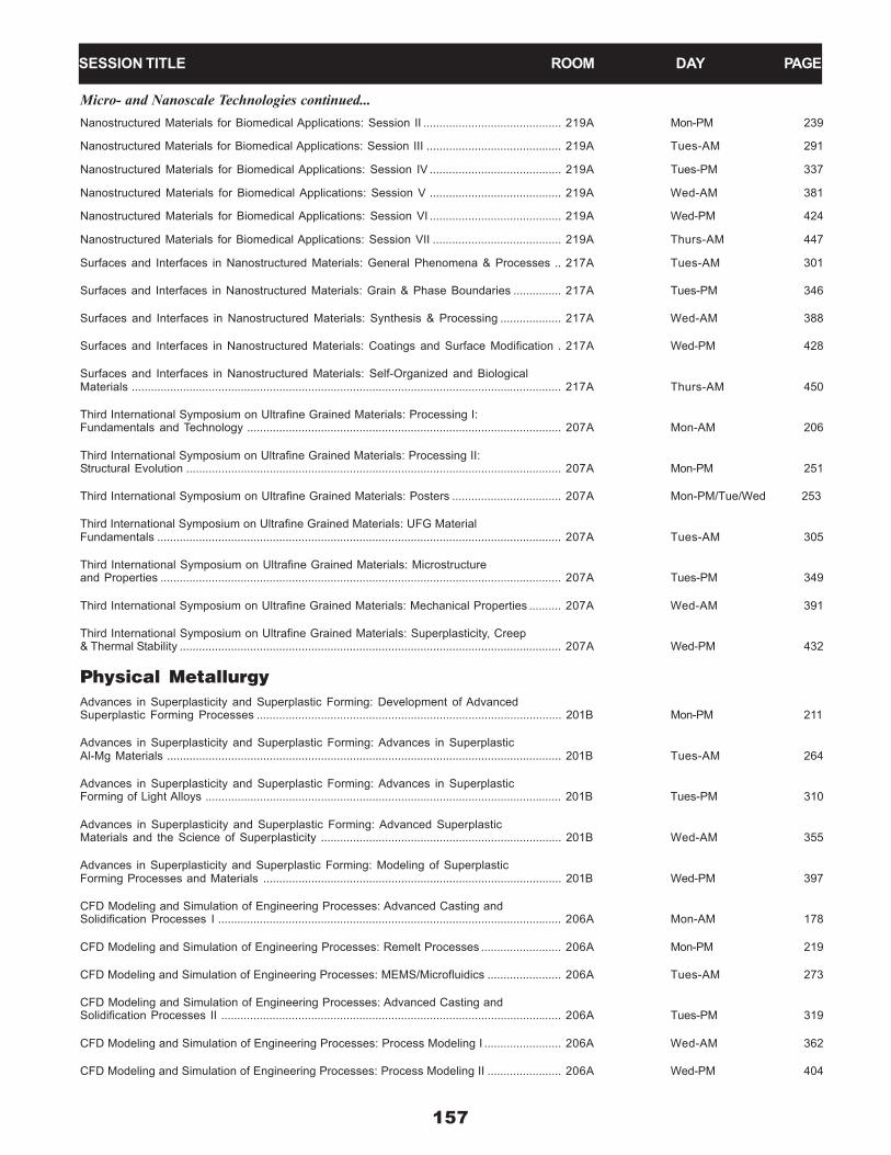
Micro- and Nanoscale Technologies continued...Nanostructured Materials for Biomedical Applications: Session II ........................................... 219A Mon-PM 239
Nanostructured Materials for Biomedical Applications: Session III .......................................... 219A Tues-AM 291
Nanostructured Materials for Biomedical Applications: Session IV ......................................... 219A Tues-PM 337
Nanostructured Materials for Biomedical Applications: Session V ......................................... 219A Wed-AM 381
Nanostructured Materials for Biomedical Applications: Session VI ......................................... 219A Wed-PM 424
Nanostructured Materials for Biomedical Applications: Session VII ........................................ 219A Thurs-AM 447
Surfaces and Interfaces in Nanostructured Materials: General Phenomena & Processes .. 217A Tues-AM 301
Surfaces and Interfaces in Nanostructured Materials: Grain & Phase Boundaries ............... 217A Tues-PM 346
Surfaces and Interfaces in Nanostructured Materials: Synthesis & Processing ................... 217A Wed-AM 388
Surfaces and Interfaces in Nanostructured Materials: Coatings and Surface Modification . 217A Wed-PM 428
Surfaces and Interfaces in Nanostructured Materials: Self-Organized and BiologicalMaterials ...................................................................................................................................... 217A Thurs-AM 450
Third International Symposium on Ultrafine Grained Materials: Processing I:Fundamentals and Technology .................................................................................................. 207A Mon-AM 206
Third International Symposium on Ultrafine Grained Materials: Processing II:Structural Evolution ..................................................................................................................... 207A Mon-PM 251
Third International Symposium on Ultrafine Grained Materials: Posters .................................. 207A Mon-PM/Tue/Wed 253
Third International Symposium on Ultrafine Grained Materials: UFG MaterialFundamentals .............................................................................................................................. 207A Tues-AM 305
Third International Symposium on Ultrafine Grained Materials: Microstructureand Properties ............................................................................................................................. 207A Tues-PM 349
Third International Symposium on Ultrafine Grained Materials: Mechanical Properties .......... 207A Wed-AM 391
Third International Symposium on Ultrafine Grained Materials: Superplasticity, Creep& Thermal Stability ....................................................................................................................... 207A Wed-PM 432
Physical MetallurgyAdvances in Superplasticity and Superplastic Forming: Development of AdvancedSuperplastic Forming Processes ............................................................................................... 201B Mon-PM 211
Advances in Superplasticity and Superplastic Forming: Advances in SuperplasticAl-Mg Materials ........................................................................................................................... 201B Tues-AM 264
Advances in Superplasticity and Superplastic Forming: Advances in SuperplasticForming of Light Alloys ............................................................................................................... 201B Tues-PM 310
Advances in Superplasticity and Superplastic Forming: Advanced SuperplasticMaterials and the Science of Superplasticity ........................................................................... 201B Wed-AM 355
Advances in Superplasticity and Superplastic Forming: Modeling of SuperplasticForming Processes and Materials ............................................................................................. 201B Wed-PM 397
CFD Modeling and Simulation of Engineering Processes: Advanced Casting andSolidification Processes I ........................................................................................................... 206A Mon-AM 178
CFD Modeling and Simulation of Engineering Processes: Remelt Processes ......................... 206A Mon-PM 219
CFD Modeling and Simulation of Engineering Processes: MEMS/Microfluidics ....................... 206A Tues-AM 273
CFD Modeling and Simulation of Engineering Processes: Advanced Casting andSolidification Processes II .......................................................................................................... 206A Tues-PM 319
CFD Modeling and Simulation of Engineering Processes: Process Modeling I ........................ 206A Wed-AM 362
CFD Modeling and Simulation of Engineering Processes: Process Modeling II ....................... 206A Wed-PM 404
SESSION TITLE ROOM DAY PAGE

158
SESSION TITLE ROOM DAY PAGESESSION TITLE ROOM DAY PAGE
Physical Metallurgy continued...Computational Thermodynamics and Phase Transformations: Grain Growth andParticle Coarsening ..................................................................................................................... 202A Mon-AM 180
Computational Thermodynamics and Phase Transformations: Interfaces andGrain Boundaries ........................................................................................................................ 202A Mon-PM 222
Computational Thermodynamics and Phase Transformations: Phase FieldModeling I................... ................................................................................................................. 202A Tues-AM 276
Computational Thermodynamics and Phase Transformations: Phase Field Modeling II... ...... 202A Tues-PM 322
Computational Thermodynamics and Phase Transformations: Phase Equilibria andThermodynamic Assessments.................. ............................................................................... 202A Wed-AM 363
Computational Thermodynamics and Phase Transformations: Joint Session withThe Didier de Fontaine Symposium on the Thermodynamics of Alloys I...................... .......... 216B Wed-AM 389
Computational Thermodynamics and Phase Transformations: Thermodynamics andPhase Transformations............... .............................................................................................. 202A Wed-PM 405
Computational Thermodynamics and Phase Transformations: Joint Session withThe Didier de Fontaine Symposium on the Thermodynamics of Alloys II...................... ......... 216B Wed-PM 430
Dislocations: Modeling and Simulation Fundamentals ............................................................... 201A Mon-AM 182
Dislocations: Simulation and Observation of Fundamental Mechanisms ................................ 201A Mon-PM 224
Dislocations: Dislocation Structures and Patterning ................................................................. 201A Tues-AM 278
Dislocations: Novel Experimental Methods ................................................................................ 201A Tues-PM 324
Dislocations: Plasticity, Voids, and Fracture ............................................................................. 201A Wed-AM 365
Dislocations: Dislocations in Complex Materials ....................................................................... 201A Wed-PM 407
Electrochemical Measurements and Processing of Materials: ElectrodepositionProcesses ................................................................................................................................... 212A Tues-AM 280
Electrochemical Measurements and Processing of Materials: Electrochemical Refining ....... 212A Tues-PM 325
Electrochemical Measurements and Processing of Materials: Electrochemical MetalProduction ................................................................................................................................... 212A Wed-AM 366
Electrochemical Measurements and Processing of Materials: Electrochemical Sensorsand Measurements ..................................................................................................................... 212A Wed-PM 409
Failure of Structural Materials: Fundamentals ........................................................................... 211A Wed-AM 367
Failure of Structural Materials: Fatigue ...................................................................................... 211A Wed-PM 410
Failure of Structural Materials: General ..................................................................................... 211A Thurs-AM 441
Hume Rothery Symposium: Structure and Diffusional Growth Mechanisms of IrrationalInterphase Boundaries: Session I .............................................................................................. 208A Mon-AM 186
Hume Rothery Symposium: Structure and Diffusional Growth Mechanisms of IrrationalInterphase Boundaries: Session II ............................................................................................. 208A Mon-PM 228
Hume Rothery Symposium: Structure and Diffusional Growth Mechanisms of IrrationalInterphase Boundaries: Session III ............................................................................................ 208A Tues-AM 282
Hume Rothery Symposium: Structure and Diffusional Growth Mechanisms of IrrationalInterphase Boundaries: Session IV ........................................................................................... 208A Tues-PM 327
Hume Rothery Symposium: Structure and Diffusional Growth Mechanisms of IrrationalInterphase Boundaries: Session V ............................................................................................ 208A Wed-AM 370
Hume Rothery Symposium: Structure and Diffusional Growth Mechanisms of IrrationalInterphase Boundaries: Session VI ........................................................................................... 208A Wed-PM 415

159
Physical Metallurgy continued...Internal Stresses and Thermo-Mechanical Behavior in Multi-Component MaterialsSystems: Electronic Thin Films and Packaging Materials I ....................................................... 209B Mon-AM 187
Internal Stresses and Thermo-Mechanical Behavior in Multi-Component MaterialsSystems: Electronic Thin Films and Packagaing Materials II ..................................................... 209B Mon-PM 229
Internal Stresses and Thermo-Mechanical Behavior in Multi-Component MaterialsSystems: Creep and Plasticity I .................................................................................................. 209B Tues-AM 283
Internal Stresses and Thermo-Mechanical Behavior in Multi-Component MaterialsSystems: Creep and Plasticity II ................................................................................................. 209B Tues-PM 327
Internal Stresses and Thermo-Mechanical Behavior in Multi-Component MaterialsSystems: Anisotropy and Residual Stresses ............................................................................ 209B Wed-AM 371
Multiphase Phenomena in Materials Processing: Session I ...................................................... 218B Wed-AM 379
Multiphase Phenomena in Materials Processing: Session II ..................................................... 218B Wed-PM 423
Multiphase Phenomena in Materials Processing: Session III .................................................... 218B Thurs-AM 446
R.J. Arsenault Symposium on Materials Testing and Evaluation: Session I ............................ 211A Mon-AM 201
R.J. Arsenault Symposium on Materials Testing and Evaluation: Session II ............................ 211A Mon-PM 246
R.J. Arsenault Symposium on Materials Testing and Evaluation: Session III ........................... 211A Tues-AM 296
R.J. Arsenault Symposium on Materials Testing and Evaluation: Session IV .......................... 211A Tues-PM 342
Solidification Processes and Microstructures: A Symposium in Honor of Prof. W.Kurz: Processes ......................................................................................................................... 207D Mon-AM 202
Solidification Processes and Microstructures: A Symposium in Honor of Prof. W.Kurz: Mushy Zone Dynamics ..................................................................................................... 207D Mon-PM 247
Solidification Processes and Microstructures: A Symposium in Honor of Prof. W.Kurz: Microstructures ................................................................................................................. 207D Tues-AM 299
Solidification Processes and Microstructures: A Symposium in Honor of Prof. W.Kurz: Rapid Solidification ........................................................................................................... 207D Tues-PM 344
Solidification Processes and Microstructures: A Symposium in Honor of Prof. W.Kurz: Phase Field ........................................................................................................................ 207D Wed-AM 386
Symposium on Microstructural Stability in Honor of Prof. Roger D. Doherty:Microstructural Stability: Recrystallization ................................................................................. 216A Mon-AM 204
Symposium on Microstructural Stability in Honor of Prof. Roger D. Doherty:Microstructural Stability: Texture Development ......................................................................... 216A Mon-PM 249
Symposium on Microstructural Stability in Honor of Prof. Roger D. Doherty:Microstructural Stability: Plastic Deformation ............................................................................ 216A Tues-AM 302
Symposium on Microstructural Stability in Honor of Prof. Roger D. Doherty:Microstructural Stability: Precipitation and Other Topics .......................................................... 216A Tues-PM 347
The Didier de Fontaine Symposium on the Thermodynamics of Alloys: Fundamentalsof Alloy Theory ........................................................................................................................... 216B Mon-AM 205
The Didier de Fontaine Symposium on the Thermodynamics of Alloys: ExperimentalTechniques .................................................................................................................................. 216B Mon-PM 250
The Didier de Fontaine Symposium on the Thermodynamics of Alloys: First PrincipleCalculations and Cluster Expansion Techniques ...................................................................... 216B Tues-AM 304
The Didier de Fontaine Symposium on the Thermodynamics of Alloys: InteratomicPotentials and Cluster Expansion Techniques .......................................................................... 216B Tues-PM 348
The Didier de Fontaine Symposium on the Thermodynamics of Alloys: Joint Sessionwith Computational Thermodynamics and Phase Transformations I ....................................... 216B Wed-AM 389
SESSION TITLE ROOM DAY PAGE

160
Physical Metallurgy continued...The Didier de Fontaine Symposium on the Thermodynamics of Alloys: Joint Sessionwith Computational Thermodynamics and Phase Transformations II ...................................... 216B Wed-PM 430
The Role of Grain Boundaries in Material Design: Grain Boundary Character ....................... 218A Wed-AM 390
The Role of Grain Boundaries in Material Design: Grain Boundary Segregation,Diffusion, Damage ...................................................................................................................... 218A Wed-PM 431
The Role of Grain Boundaries in Material Design: Simulation of Grain BoundaryEffects of Properties .................................................................................................................. 218A Thurs-AM 451
General AbstractsGeneral Abstracts: Session I ..................................................................................................... 204 Mon-AM 184
General Abstracts: Session II .................................................................................................... 204 Mon-PM 225
General Abstracts: Session III .................................................................................................... 212A Mon-PM 226
General Abstracts: Session IV .................................................................................................. 204 Tues-AM 281
General Abstracts: Session V ................................................................................................... 204 Tues-PM 326
General Abstracts: Session VI .................................................................................................. 208B Wed-AM 368
General Abstracts: Session VII .................................................................................................. 208B Wed-PM 411
General Abstracts: Session VIII ................................................................................................. 207D Wed-PM 412
General Abstracts: Session IX ................................................................................................... 201B Thurs-AM 441
General Poster SessionGeneral Poster Session ............................................................................................................. Ballroom Foyer MonPM-WedPM 453
SESSION TITLE ROOM DAY PAGE
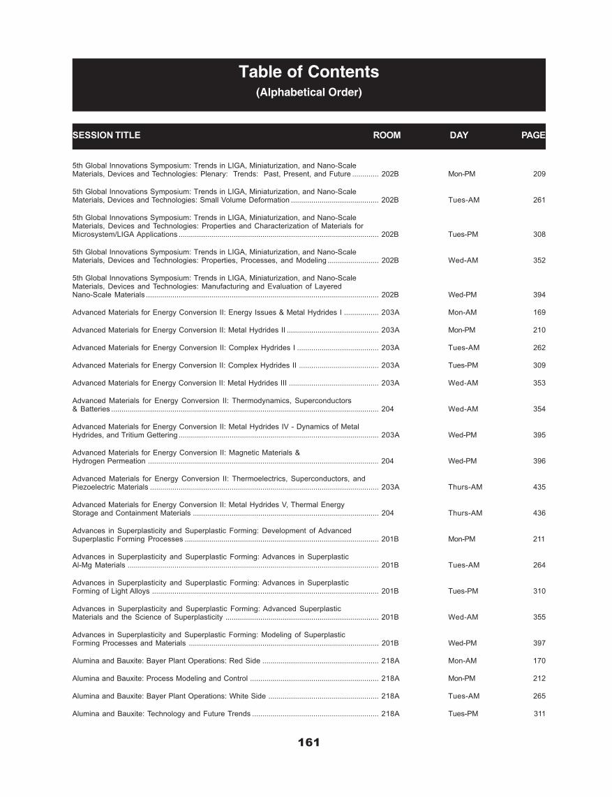
161
5th Global Innovations Symposium: Trends in LIGA, Miniaturization, and Nano-ScaleMaterials, Devices and Technologies: Plenary: Trends: Past, Present, and Future ............. 202B Mon-PM 209
5th Global Innovations Symposium: Trends in LIGA, Miniaturization, and Nano-ScaleMaterials, Devices and Technologies: Small Volume Deformation ........................................... 202B Tues-AM 261
5th Global Innovations Symposium: Trends in LIGA, Miniaturization, and Nano-ScaleMaterials, Devices and Technologies: Properties and Characterization of Materials forMicrosystem/LIGA Applications .................................................................................................. 202B Tues-PM 308
5th Global Innovations Symposium: Trends in LIGA, Miniaturization, and Nano-ScaleMaterials, Devices and Technologies: Properties, Processes, and Modeling ......................... 202B Wed-AM 352
5th Global Innovations Symposium: Trends in LIGA, Miniaturization, and Nano-ScaleMaterials, Devices and Technologies: Manufacturing and Evaluation of LayeredNano-Scale Materials .................................................................................................................. 202B Wed-PM 394
Advanced Materials for Energy Conversion II: Energy Issues & Metal Hydrides I ................. 203A Mon-AM 169
Advanced Materials for Energy Conversion II: Metal Hydrides II ............................................. 203A Mon-PM 210
Advanced Materials for Energy Conversion II: Complex Hydrides I ........................................ 203A Tues-AM 262
Advanced Materials for Energy Conversion II: Complex Hydrides II ....................................... 203A Tues-PM 309
Advanced Materials for Energy Conversion II: Metal Hydrides III ............................................ 203A Wed-AM 353
Advanced Materials for Energy Conversion II: Thermodynamics, Superconductors& Batteries ................................................................................................................................... 204 Wed-AM 354
Advanced Materials for Energy Conversion II: Metal Hydrides IV - Dynamics of MetalHydrides, and Tritium Gettering .................................................................................................. 203A Wed-PM 395
Advanced Materials for Energy Conversion II: Magnetic Materials &Hydrogen Permeation ................................................................................................................. 204 Wed-PM 396
Advanced Materials for Energy Conversion II: Thermoelectrics, Superconductors, andPiezoelectric Materials ................................................................................................................ 203A Thurs-AM 435
Advanced Materials for Energy Conversion II: Metal Hydrides V, Thermal EnergyStorage and Containment Materials ........................................................................................... 204 Thurs-AM 436
Advances in Superplasticity and Superplastic Forming: Development of AdvancedSuperplastic Forming Processes ............................................................................................... 201B Mon-PM 211
Advances in Superplasticity and Superplastic Forming: Advances in SuperplasticAl-Mg Materials ........................................................................................................................... 201B Tues-AM 264
Advances in Superplasticity and Superplastic Forming: Advances in SuperplasticForming of Light Alloys ............................................................................................................... 201B Tues-PM 310
Advances in Superplasticity and Superplastic Forming: Advanced SuperplasticMaterials and the Science of Superplasticity ........................................................................... 201B Wed-AM 355
Advances in Superplasticity and Superplastic Forming: Modeling of SuperplasticForming Processes and Materials ............................................................................................. 201B Wed-PM 397
Alumina and Bauxite: Bayer Plant Operations: Red Side ......................................................... 218A Mon-AM 170
Alumina and Bauxite: Process Modeling and Control ............................................................... 218A Mon-PM 212
Alumina and Bauxite: Bayer Plant Operations: White Side ...................................................... 218A Tues-AM 265
Alumina and Bauxite: Technology and Future Trends .............................................................. 218A Tues-PM 311
SESSION TITLE ROOM DAY PAGE
Table of Contents(Alphabetical Order)

162
Aluminum Can Recycling: Session I .......................................................................................... 217D Tues-AM 266
Aluminum Reduction - Potroom Improvements .......................................................................... 213D Mon-AM 171
Aluminum Reduction Technology: Cell Development and Operations ...................................... 213D Mon-PM 212
Aluminum Reduction Technology: Pot Control ........................................................................... 213D Tues-AM 267
Aluminum Reduction Technology: Modeling - Industry Trends ................................................ 213D Tues-PM 312
Aluminum Reduction Technology: Emerging Technologies ....................................................... 213D Wed-AM 356
Aluminum Reduction Technology: Environmental ...................................................................... 213D Wed-PM 398
Aluminum Reduction Technology: Materials and Fundamentals .............................................. 213A Wed-PM 399
Aluminum Reduction Technology: Modeling .............................................................................. 213D Thurs-AM 437
Automotive Alloys 2004: Session I ............................................................................................ 210A Mon-AM 172
Automotive Alloys 2004: Session II ........................................................................................... 210A Mon-PM 213
Automotive Alloys 2004: Session III ........................................................................................... 210A Tues-AM 268
Automotive Alloys 2004: Session IV ......................................................................................... 210A Tues-PM 313
Beyond Nickel-Base Superalloys: Superalloys and Niobium Silicides ..................................... 211B Mon-AM 174
Beyond Nickel-Base Superalloys: Molybdenum Silicides I ....................................................... 211B Mon-PM 215
Beyond Nickel-Base Superalloys: Precious Metal Alloys ......................................................... 211B Tues-AM 269
Beyond Nickel-Base Superalloys: Molybdenum Silicides II ...................................................... 211B Tues-PM 315
Beyond Nickel-Base Superalloys: Niobium Silicides ................................................................. 211B Wed-AM 357
Beyond Nickel-Base Superalloys: Other Systems and Physical Properties of Silicides ........ 211B Wed-PM 400
Bulk Metallic Glasses: Processing I ........................................................................................... 209A Mon-AM 175
Bulk Metallic Glasses: Processing II .......................................................................................... 209A Mon-PM 216
Bulk Metallic Glasses: Fatigue and Fracture ............................................................................. 209A Tues-AM 270
Bulk Metallic Glasses: Theoretical Modeling and Shear Bands ............................................... 209A Tues-PM 316
Bulk Metallic Glasses: Bio, Corrosion, and Fracture Behavior ................................................ 209A Wed-AM 359
Bulk Metallic Glasses: Phase Transformation and Alloy Design .............................................. 209A Wed-PM 402
Bulk Metallic Glasses: Mechanical Behavior ............................................................................. 209A Thurs-AM 438
Carbon Technology: Cathode Material and Corrosion .............................................................. 213A Mon-AM 176
Carbon Technology: Anode Raw Materials ............................................................................... 213A Mon-PM 217
Carbon Technology: Green Anodes and Soderberg Paste ...................................................... 213A Tues-AM 272
Carbon Technology: Anode Baking ............................................................................................ 213A Tues-PM 317
Carbon Technology: Anode Quality and Performance ............................................................. 213A Wed-AM 360
Cast Shop Technology: Melting and Refractories ..................................................................... 213B/C Mon-AM 177
Cast Shop Technology: Modeling of Casting Processes ......................................................... 213B/C Mon-PM 218
Cast Shop Technology: Casting ................................................................................................. 213B/C Tues-AM 272
Cast Shop Technology: Metal Treatment ................................................................................... 213B/C Tues-PM 318
Cast Shop Technology: Alloying and Furnace Processing ...................................................... 213B/C Wed-AM 361
SESSION TITLE ROOM DAY PAGE

163
Cast Shop Technology: Grain Refining ...................................................................................... 213B/C Wed-PM 403
Cast Shop Technology: Foundry ................................................................................................ 213B/C Thurs-AM 439
CFD Modeling and Simulation of Engineering Processes: Advanced Casting andSolidification Processes I ........................................................................................................... 206A Mon-AM 178
CFD Modeling and Simulation of Engineering Processes: Remelt Processes ......................... 206A Mon-PM 219
CFD Modeling and Simulation of Engineering Processes: MEMS/Microfluidics ....................... 206A Tues-AM 273
CFD Modeling and Simulation of Engineering Processes: Advanced Casting andSolidification Processes II .......................................................................................................... 206A Tues-PM 319
CFD Modeling and Simulation of Engineering Processes: Process Modeling I ........................ 206A Wed-AM 362
CFD Modeling and Simulation of Engineering Processes: Process Modeling II ....................... 206A Wed-PM 404
Challenges in Advanced Thin Films: Microstructures, Interfaces, and Reactions:Advances in Photonic and Optoelectronic Materials and Processes ..................................... 218B Mon-AM 179
Challenges in Advanced Thin Films: Microstructures, Interfaces, and Reactions:Microstructures, Properties, and Reliability of Microelectronic Devices ................................. 218B Mon-PM 220
Challenges in Advanced Thin Films: Microstructures, Interfaces, and Reactions:Modification, Characterization, and Modeling ........................................................................... 218B Tues-AM 274
Challenges in Advanced Thin Films: Microstructures, Interfaces, and Reactions:Design, Process, and Property Control of Functional and Structural Thin-Films .................... 218B Tues-PM 320
Computational Thermodynamics and Phase Transformations: Grain Growth andParticle Coarsening ..................................................................................................................... 202A Mon-AM 180
Computational Thermodynamics and Phase Transformations: Interfaces andGrain Boundaries ........................................................................................................................ 202A Mon-PM 222
Computational Thermodynamics and Phase Transformations: Phase FieldModeling I................... ................................................................................................................. 202A Tues-AM 276
Computational Thermodynamics and Phase Transformations: Phase Field Modeling II... ...... 202A Tues-PM 322
Computational Thermodynamics and Phase Transformations: Phase Equilibria andThermodynamic Assessments.................. ............................................................................... 202A Wed-AM 363
Computational Thermodynamics and Phase Transformations: Joint Session withThe Didier de Fontaine Symposium on the Thermodynamics of Alloys I...................... .......... 216B Wed-AM 389
Computational Thermodynamics and Phase Transformations: Thermodynamics andPhase Transformations............... .............................................................................................. 202A Wed-PM 405
Computational Thermodynamics and Phase Transformations: Joint Session withThe Didier de Fontaine Symposium on the Thermodynamics of Alloys II...................... ......... 216B Wed-PM 430
Cost-Affordable Titanium Symposium Dedicated to Prof. Harvey Flower: Overview andInnovative Processes..................... ........................................................................................... 206B Mon-AM 182
Cost-Affordable Titanium Symposium Dedicated to Prof. Harvey Flower: BreakThrough Technologies ................................................................................................................ 206B Mon-PM 223
Cost-Affordable Titanium Symposium Dedicated to Prof. Harvey Flower:Titanium Economics .................................................................................................................... 206B Tues-AM 278
Cost-Affordable Titanium Symposium Dedicated to Prof. Harvey Flower: CreativeProcessing .................................................................................................................................. 206B Tues-PM 323
Cost-Affordable Titanium Symposium Dedicated to Prof. Harvey Flower: CreativeFabrication ................................................................................................................................... 206B Wed-AM 364
Cost-Affordable Titanium Symposium Dedicated to Prof. Harvey Flower: Low CostTitanium ....................................................................................................................................... 206B Wed-PM 406
Cost-Affordable Titanium Symposium Dedicated to Prof. Harvey Flower:Property Enhancement ............................................................................................................... 206B Thurs-AM 440
SESSION TITLE ROOM DAY PAGE
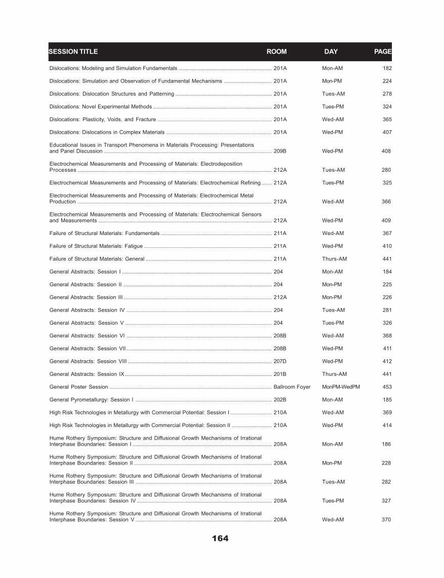
164
SESSION TITLE ROOM DAY PAGE
Dislocations: Modeling and Simulation Fundamentals ............................................................... 201A Mon-AM 182
Dislocations: Simulation and Observation of Fundamental Mechanisms ................................ 201A Mon-PM 224
Dislocations: Dislocation Structures and Patterning ................................................................. 201A Tues-AM 278
Dislocations: Novel Experimental Methods ................................................................................ 201A Tues-PM 324
Dislocations: Plasticity, Voids, and Fracture ............................................................................. 201A Wed-AM 365
Dislocations: Dislocations in Complex Materials ....................................................................... 201A Wed-PM 407
Educational Issues in Transport Phenomena in Materials Processing: Presentationsand Panel Discussion ................................................................................................................. 209B Wed-PM 408
Electrochemical Measurements and Processing of Materials: ElectrodepositionProcesses ................................................................................................................................... 212A Tues-AM 280
Electrochemical Measurements and Processing of Materials: Electrochemical Refining ....... 212A Tues-PM 325
Electrochemical Measurements and Processing of Materials: Electrochemical MetalProduction ................................................................................................................................... 212A Wed-AM 366
Electrochemical Measurements and Processing of Materials: Electrochemical Sensorsand Measurements ..................................................................................................................... 212A Wed-PM 409
Failure of Structural Materials: Fundamentals ........................................................................... 211A Wed-AM 367
Failure of Structural Materials: Fatigue ...................................................................................... 211A Wed-PM 410
Failure of Structural Materials: General ..................................................................................... 211A Thurs-AM 441
General Abstracts: Session I ..................................................................................................... 204 Mon-AM 184
General Abstracts: Session II .................................................................................................... 204 Mon-PM 225
General Abstracts: Session III .................................................................................................... 212A Mon-PM 226
General Abstracts: Session IV .................................................................................................. 204 Tues-AM 281
General Abstracts: Session V ................................................................................................... 204 Tues-PM 326
General Abstracts: Session VI .................................................................................................. 208B Wed-AM 368
General Abstracts: Session VII .................................................................................................. 208B Wed-PM 411
General Abstracts: Session VIII ................................................................................................. 207D Wed-PM 412
General Abstracts: Session IX ................................................................................................... 201B Thurs-AM 441
General Poster Session ............................................................................................................. Ballroom Foyer MonPM-WedPM 453
General Pyrometallurgy: Session I ............................................................................................ 202B Mon-AM 185
High Risk Technologies in Metallurgy with Commercial Potential: Session I ............................ 210A Wed-AM 369
High Risk Technologies in Metallurgy with Commercial Potential: Session II ........................... 210A Wed-PM 414
Hume Rothery Symposium: Structure and Diffusional Growth Mechanisms of IrrationalInterphase Boundaries: Session I .............................................................................................. 208A Mon-AM 186
Hume Rothery Symposium: Structure and Diffusional Growth Mechanisms of IrrationalInterphase Boundaries: Session II ............................................................................................. 208A Mon-PM 228
Hume Rothery Symposium: Structure and Diffusional Growth Mechanisms of IrrationalInterphase Boundaries: Session III ............................................................................................ 208A Tues-AM 282
Hume Rothery Symposium: Structure and Diffusional Growth Mechanisms of IrrationalInterphase Boundaries: Session IV ........................................................................................... 208A Tues-PM 327
Hume Rothery Symposium: Structure and Diffusional Growth Mechanisms of IrrationalInterphase Boundaries: Session V ............................................................................................ 208A Wed-AM 370

165
Hume Rothery Symposium: Structure and Diffusional Growth Mechanisms of IrrationalInterphase Boundaries: Session VI ........................................................................................... 208A Wed-PM 415
Internal Stresses and Thermo-Mechanical Behavior in Multi-Component MaterialsSystems: Electronic Thin Films and Packaging Materials I ....................................................... 209B Mon-AM 187
Internal Stresses and Thermo-Mechanical Behavior in Multi-Component MaterialsSystems: Electronic Thin Films and Packagaing Materials II ..................................................... 209B Mon-PM 229
Internal Stresses and Thermo-Mechanical Behavior in Multi-Component MaterialsSystems: Creep and Plasticity I .................................................................................................. 209B Tues-AM 283
Internal Stresses and Thermo-Mechanical Behavior in Multi-Component MaterialsSystems: Creep and Plasticity II ................................................................................................. 209B Tues-PM 327
Internal Stresses and Thermo-Mechanical Behavior in Multi-Component MaterialsSystems: Anisotropy and Residual Stresses ............................................................................ 209B Wed-AM 371
International Laterite Nickel Symposium - 2004: Economics and Project Assessment .......... 217B/C Mon-AM 188
International Laterite Nickel Symposium - 2004: Mineralogy and Geometallurgy .................... 217B/C Mon-PM 230
International Laterite Nickel Symposium - 2004: Panel Discussion .......................................... 217B/C Mon-PM 231
International Laterite Nickel Symposium - 2004: Pressure Acid Leaching .............................. 217B/C Tues-AM 284
International Laterite Nickel Symposium - 2004: Process Development for ProspectiveProjects ....................................................................................................................................... 217B/C Tues-PM 328
International Laterite Nickel Symposium - 2004: Roasting and Smelting ................................. 217D Tues-PM 330
International Laterite Nickel Symposium - 2004: Process and Operational LessonsLearned - Part I ........................................................................................................................... 217B/C Wed-AM 372
International Laterite Nickel Symposium - 2004: Process and Operational LessonsLearned - Part II .......................................................................................................................... 217B/C Wed-PM 415
International Laterite Nickel Symposium - 2004: Atmospheric Leaching ................................. 217B/C Thurs-AM 443
International Laterite Nickel Symposium - 2004: Slurry Rheology, Solution Extractionand Other .................................................................................................................................... 217B/C Thurs-AM 443
Lead-Free Solders and Processing Issues Relevant to Microelectronic Packaging:Fundamentals, Phases, Wetting and Solidification ................................................................... 219B Mon-AM 189
Lead-Free Solders and Processing Issues Relevant to Microelectronic Packaging:Environmental and Materials Issues for Lead-Free .................................................................. 219B Mon-PM 231
Lead-Free Solders and Processing Issues Relevant to Microelectronic Packaging:Mechanical Properties and Fatigue Behavior ........................................................................... 219B Tues-AM 285
Lead-Free Solders and Processing Issues Relevant to Microelectronic Packaging:Electromigration and Creep in Leadfree Solders ...................................................................... 219B Tues-PM 331
Lead-Free Solders and Processing Issues Relevant to Microelectronic Packaging:Interfacial Interactions, Intermetallics and Substrates ............................................................. 219B Wed-AM 373
Lead-Free Solders and Processing Issues Relevant to Microelectronic Packaging:Microstructural Characterization and Evolution ........................................................................ 219B Wed-PM 416
Magnesium Technology 2004: Automotive Applications/Welding ............................................. 203B Mon-AM 191
Magnesium Technology 2004: Wrought Magnesium Alloys I .................................................... 203B Mon-PM 233
Magnesium Technology 2004: Wrought Magnesium Alloys II/Corrosion and Coatings ........... 203B Tues-AM 287
Magnesium Technology 2004: Primary Processing and Environmental Issues ...................... 203B Tues-PM 332
Magnesium Technology 2004: Casting Processes and Properties .......................................... 203B Wed-AM 375
Magnesium Technology 2004: Fundamental Research ............................................................ 203B Wed-PM 417
Magnesium Technology 2004: Alloy Development .................................................................... 203B Thurs-AM 444
SESSION TITLE ROOM DAY PAGE

166
Materials Analysis: Understanding the Columbia Disaster ....................................................... Ballroom B Wed-PM 418
Materials by Design: Atoms to Applications: Materials Chemistry and Alloy Design .............. 210B Mon-AM 192
Materials by Design: Atoms to Applications: Materials Characterization andMicrostructural Modeling ............................................................................................................ 210B Mon-PM 234
Materials by Design: Atoms to Applications: Computational and Experimental Strategies ...... 210B Tues-AM 288
Materials by Design: Atoms to Applications: Designing Nanostructures ................................. 210B Tues-PM 334
Materials by Design: Atoms to Applications: Design for Mechanical Functionality I ............... 210B Wed-AM 376
Materials by Design: Atoms to Applications: Design for Mechanical Functionality II .............. 210B Wed-PM 419
Materials Education to Revitalize the Workforce: Session I ..................................................... 217D Wed-AM 377
Materials Education to Revitalize the Workforce: Session II .................................................... 217D Wed-PM 420
Materials Issues in Fuel Cells: State-of-the-Art ........................................................................ 207B/C Mon-AM 193
Materials Issues in Fuel Cell: Materials Challenges .................................................................. 207B/C Mon-PM 235
Materials Processing Fundamentals: Solidification and Casting .............................................. 212B Mon-AM 194
Materials Processing Fundamentals: Deformation Processing ................................................ 212B Mon-PM 236
Materials Processing Fundamentals: Liquid Metal Processing ................................................ 212B Tues-AM 289
Materials Processing Fundamentals: Smelting and Refining .................................................... 212B Tues-PM 335
Materials Processing Fundamentals: Aqueous Processing ..................................................... 212B Wed-AM 378
Materials Processing Fundamentals: Powders, Composites, Coatings and Measurements . 212B Wed-PM 420
Metals for the Future: Structural Materials ................................................................................ 215 Wed-AM 379
Metals for the Future: Functional Materials ............................................................................... 215 Wed-PM 422
Metals for the Future: Processing and Bio-Materials ............................................................... 215 Thurs-AM 445
Multiphase Phenomena in Materials Processing: Session I ...................................................... 218B Wed-AM 379
Multiphase Phenomena in Materials Processing: Session II ..................................................... 218B Wed-PM 423
Multiphase Phenomena in Materials Processing: Session III .................................................... 218B Thurs-AM 446
Nanostructured Magnetic Materials: Recent Progress in Magnetic Nanostructures .............. 215 Mon-AM 195
Nanostructured Magnetic Materials: Synthesis and Characterization of NanostructuredMagnetic Materials ...................................................................................................................... 215 Mon-PM 237
Nanostructured Magnetic Materials: Magnetic Tunnel Junctions and SemiconductorSpintronics ................................................................................................................................... 215 Tues-AM 290
Nanostructured Magnetic Materials: Self Assembly and Patterned Nanostructures ............. 215 Tues-PM 336
Nanostructured Materials for Biomedical Applications: Session I ........................................... 219A Mon-AM 197
Nanostructured Materials for Biomedical Applications: Session II ........................................... 219A Mon-PM 239
Nanostructured Materials for Biomedical Applications: Session III .......................................... 219A Tues-AM 291
Nanostructured Materials for Biomedical Applications: Session IV ......................................... 219A Tues-PM 337
Nanostructured Materials for Biomedical Applications: Session V ......................................... 219A Wed-AM 381
Nanostructured Materials for Biomedical Applications: Session VI ......................................... 219A Wed-PM 424
Nanostructured Materials for Biomedical Applications: Session VII ........................................ 219A Thurs-AM 447
Phase Stability, Phase Transformation, and Reactive Phase Formation in ElectronicMaterials III: Session I ................................................................................................................. 214 Mon-AM 198
SESSION TITLE ROOM DAY PAGE

167
SESSION TITLE ROOM DAY PAGESESSION TITLE ROOM DAY PAGE
Phase Stability, Phase Transformation, and Reactive Phase Formation in ElectronicMaterials III: Session II ................................................................................................................. 214 Mon-PM 240
Phase Stability, Phase Transformation, and Reactive Phase Formation in ElectronicMaterials III: Session III ................................................................................................................ 214 Tues-AM 293
Phase Stability, Phase Transformation, and Reactive Phase Formation in ElectronicMaterials III: Session IV ............................................................................................................... 214 Tues-PM 338
Phase Stability, Phase Transformation, and Reactive Phase Formation in ElectronicMaterials III: Session V ............................................................................................................... 214 Wed-AM 382
Phase Transformations and Deformation in Magnesium Alloys: Solidification andPrecipitation ................................................................................................................................. 205 Tues-AM 294
Phase Transformations and Deformation in Magnesium Alloys: Plastic Deformationand Texture ................................................................................................................................. 205 Tues-PM 339
Phase Transformations and Deformation in Magnesium Alloys: Creep Deformation ............. 205 Wed-AM 383
Phase Transformations and Deformation in Magnesium Alloys: Deformation andStrengthening .............................................................................................................................. 205 Wed-PM 425
Processing, Microstructure and Properties of Powder-Based Materials: Session I .............. 208B Mon-PM 242
Processing, Microstructure and Properties of Powder-Based Materials: Session II ............. 208B Tues-AM 295
Processing, Microstructure and Properties of Powder-Based Materials: Session III ............ 208B Tues-PM 340
Recent Advances in Non-Ferrous Metals Processing: Reactive Metals ................................. 205 Mon-AM 199
Recent Advances in Non-Ferrous Metals Processing: Sustainable Development ................. 205 Mon-PM 244
Recycling: General Recycling .................................................................................................... 217D Mon-AM 200
Recycling: Aluminum and Aluminum Dross Processing ............................................................ 217D Mon-PM 244
Roytburd Symposium on Polydomain Structures: Elastic Domains in Structural Materials ..... 216A Wed-AM 384
Roytburd Symposium on Polydomain Structures: Domains in Ferroelectrics and Magnetics 216A Wed-PM 425
R.J. Arsenault Symposium on Materials Testing and Evaluation: Session I ............................ 211A Mon-AM 201
R.J. Arsenault Symposium on Materials Testing and Evaluation: Session II ............................ 211A Mon-PM 246
R.J. Arsenault Symposium on Materials Testing and Evaluation: Session III ........................... 211A Tues-AM 296
R.J. Arsenault Symposium on Materials Testing and Evaluation: Session IV .......................... 211A Tues-PM 342
Solid and Aqueous Wastes from Non-Ferrous Metal Industry: Session I ............................... 214 Wed-PM 426
Solid and Aqueous Wastes from Non-Ferrous Metal Industry: Session II .............................. 214 Thurs-AM 448
Solidification of Aluminum Alloys: Microstructural Evolution I ................................................... 207B/C Tues-AM 298
Solidification of Aluminum Alloys: Microstructural Evolution II .................................................. 207B/C Tues-PM 343
Solidification of Aluminum Alloys: Solidification Cracking/Mechanical Properties ................... 207B/C Wed-AM 385
Solidification of Aluminum Alloys: Gas Porosity/Micro-Macro Segregation ............................. 207B/C Wed-PM 427
Solidification of Aluminum Alloys: Special Effects ..................................................................... 207B/C Thurs-AM 449
Solidification Processes and Microstructures: A Symposium in Honor of Prof. W.Kurz: Processes ......................................................................................................................... 207D Mon-AM 202
Solidification Processes and Microstructures: A Symposium in Honor of Prof. W.Kurz: Mushy Zone Dynamics ..................................................................................................... 207D Mon-PM 247
Solidification Processes and Microstructures: A Symposium in Honor of Prof. W.Kurz: Microstructures ................................................................................................................. 207D Tues-AM 299
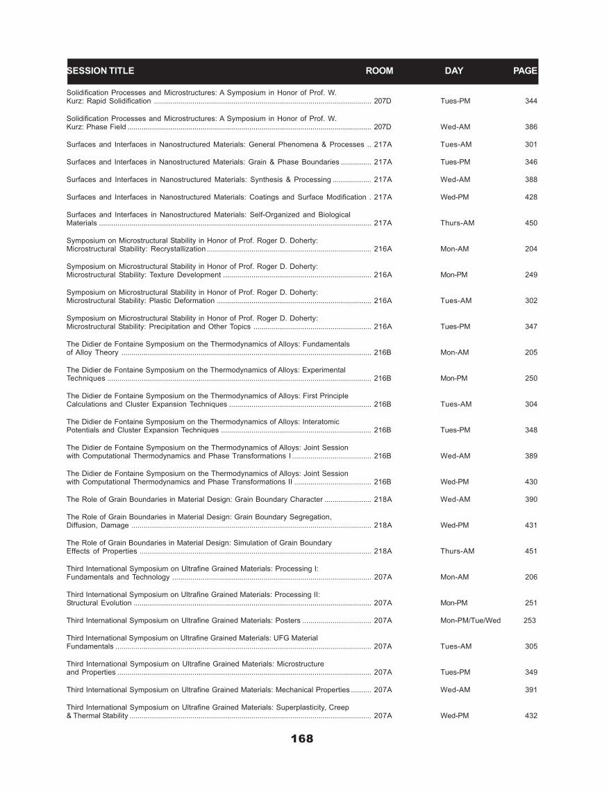
168
Solidification Processes and Microstructures: A Symposium in Honor of Prof. W.Kurz: Rapid Solidification ........................................................................................................... 207D Tues-PM 344
Solidification Processes and Microstructures: A Symposium in Honor of Prof. W.Kurz: Phase Field ........................................................................................................................ 207D Wed-AM 386
Surfaces and Interfaces in Nanostructured Materials: General Phenomena & Processes .. 217A Tues-AM 301
Surfaces and Interfaces in Nanostructured Materials: Grain & Phase Boundaries ............... 217A Tues-PM 346
Surfaces and Interfaces in Nanostructured Materials: Synthesis & Processing ................... 217A Wed-AM 388
Surfaces and Interfaces in Nanostructured Materials: Coatings and Surface Modification . 217A Wed-PM 428
Surfaces and Interfaces in Nanostructured Materials: Self-Organized and BiologicalMaterials ...................................................................................................................................... 217A Thurs-AM 450
Symposium on Microstructural Stability in Honor of Prof. Roger D. Doherty:Microstructural Stability: Recrystallization ................................................................................. 216A Mon-AM 204
Symposium on Microstructural Stability in Honor of Prof. Roger D. Doherty:Microstructural Stability: Texture Development ......................................................................... 216A Mon-PM 249
Symposium on Microstructural Stability in Honor of Prof. Roger D. Doherty:Microstructural Stability: Plastic Deformation ............................................................................ 216A Tues-AM 302
Symposium on Microstructural Stability in Honor of Prof. Roger D. Doherty:Microstructural Stability: Precipitation and Other Topics .......................................................... 216A Tues-PM 347
The Didier de Fontaine Symposium on the Thermodynamics of Alloys: Fundamentalsof Alloy Theory ........................................................................................................................... 216B Mon-AM 205
The Didier de Fontaine Symposium on the Thermodynamics of Alloys: ExperimentalTechniques .................................................................................................................................. 216B Mon-PM 250
The Didier de Fontaine Symposium on the Thermodynamics of Alloys: First PrincipleCalculations and Cluster Expansion Techniques ...................................................................... 216B Tues-AM 304
The Didier de Fontaine Symposium on the Thermodynamics of Alloys: InteratomicPotentials and Cluster Expansion Techniques .......................................................................... 216B Tues-PM 348
The Didier de Fontaine Symposium on the Thermodynamics of Alloys: Joint Sessionwith Computational Thermodynamics and Phase Transformations I ....................................... 216B Wed-AM 389
The Didier de Fontaine Symposium on the Thermodynamics of Alloys: Joint Sessionwith Computational Thermodynamics and Phase Transformations II ...................................... 216B Wed-PM 430
The Role of Grain Boundaries in Material Design: Grain Boundary Character ....................... 218A Wed-AM 390
The Role of Grain Boundaries in Material Design: Grain Boundary Segregation,Diffusion, Damage ...................................................................................................................... 218A Wed-PM 431
The Role of Grain Boundaries in Material Design: Simulation of Grain BoundaryEffects of Properties .................................................................................................................. 218A Thurs-AM 451
Third International Symposium on Ultrafine Grained Materials: Processing I:Fundamentals and Technology .................................................................................................. 207A Mon-AM 206
Third International Symposium on Ultrafine Grained Materials: Processing II:Structural Evolution ..................................................................................................................... 207A Mon-PM 251
Third International Symposium on Ultrafine Grained Materials: Posters .................................. 207A Mon-PM/Tue/Wed 253
Third International Symposium on Ultrafine Grained Materials: UFG MaterialFundamentals .............................................................................................................................. 207A Tues-AM 305
Third International Symposium on Ultrafine Grained Materials: Microstructureand Properties ............................................................................................................................. 207A Tues-PM 349
Third International Symposium on Ultrafine Grained Materials: Mechanical Properties .......... 207A Wed-AM 391
Third International Symposium on Ultrafine Grained Materials: Superplasticity, Creep& Thermal Stability ....................................................................................................................... 207A Wed-PM 432
SESSION TITLE ROOM DAY PAGE
261
TU
ES
DAY
AM
TUESDAY
5th Global Innovations Symposium: Trends inLIGA, Miniaturization, and Nano-Scale Materials,Devices and Technologies: Small VolumeDeformationSponsored by: Materials Processing & Manufacturing Division,MPMD-Powder Materials Committee, MPMD-Phase Transforma-tions Committee-(Jt. ASM-MSCTS), MPMD-ComputationalMaterials Science & Engineering-(Jt. ASM-MSCTS), MPMD/EPD-Process Modeling Analysis & Control Committee, MPMD-SurfaceEngineering Committee, MPMD-Shaping and Forming Committee,MPMD-Solidification CommitteeProgram Organizers: John E. Smugeresky, Sandia NationalLaboratories, Department 8724, Livermore, CA 94551-0969 USA;Steven H. Goods, Sandia National Laboratories, Livermore, CA94551-0969 USA; Sean J. Hearne, Sandia National Laboratories,Albuquerque, NM 87185-1415 USA; Neville R. Moody, SandiaNational Laboratories, Livermore, CA 94551-0969 USA
Tuesday AM Room: 202BMarch 16, 2004 Location: Charlotte Convention Center
Session Chairs: Erica T. Lilleodden, Lawrence Berkeley NationalLaboratory, Matls. Sci. Div., Berkeley, CA 94720 USA; Sean J.Hearne, Sandia National Laboratories, Nanostruct. & SemiconductorPhysics Dept., Albuquerque, NM 87185-1415 USA
8:30 AM KeynoteSome Challenges in Understanding Mechanical Properties atthe Nanometer and Micrometer Length Scales: William D. Nix1;Feng Gang1; Julia R. Greer1; 1Stanford University, Dept. of Matls. Sci.& Engrg., 416 Escondido Mall, Bldg. 550, Stanford, CA 94305-2205USA Nanomechanical devices are certain to play an important role infuture technologies. Already sensors and actuators based on MEMStechnologies are commonplace and new devices based on NEMS arejust around the corner. These developments are part of a decades-longtrend to build useful engineering devices and structures on a smaller andsmaller scale. The creation of structures and devices calls for an under-standing of the mechanical properties of materials at these small lengthscales. Size effects in plasticity are now well-known. Plastic deforma-tion in small volumes requires higher stresses than are needed forplastic flow of bulk materials. The size dependence of the hardness ofmetals is described in terms of the geometrically necessary disloca-tions created in small indentations. This can be related to the con-tinuum theory of strain gradient plasticity. It is equivalent to theeffects of fine microstructures on strength, which can also be relatedto strain gradients. But such accounts break down when the size of thedeformation volume begins to approach the spacing of individual dis-locations. In this domain the nucleation of dislocations and plasticityunder dislocation-starved conditions appears to be more importantthan strain gradients. In an effort to shed additional light on thesetopics, uniaxial compression experiments on tiny samples made byfocused ion beam machining and integrated circuit fabrication methodsare being conducted. These experiments involve by small deformationvolumes and minimal strain gradients. They lead to some surprisingresults that are not yet understood.
9:00 AMIndentation Size Effects in Face-Centered Cubic Thin Films:From Micro to Nano: Z. Zong1; J. Lou1; Y. Huang2; Y. Huang1; D.Yang3; W. O. Soboyejo1; 1Princeton University, PMI/MAE Dept., D404E. Quad., Princeton, NJ 08544 USA; 2University of Illinois, Dept. ofMech. & Industl. Engrg., 140 Mech. Engrg. Bldg., W. Green St., Ur-bana, IL 61801 USA; 3Hysitron Inc., 5721 W. 73rd St., Minneapolis,MN 55439 USA This paper presents the effects of a combined experimental andcomputational study of indentation size effects in metallic producedusing LIGA and single crystal growth techniques. These include Ni, Auand Ag single crystals with 001, 110 and 111 orientations and LIGA NiMEMS structures. Indentation size effects are studied in these systemsusing a combination of Vickers, Berkovitch and cube cornered indent-ers. Strong indentation size effects are reported for indents with sizesbetween the micron- and nano-scales. Sharper indenters are also shown
to result in stronger size effects than blunter indenters. The measuredtrends in the indentation size effects are predicted using mechanism-based strain gradient plasticity theories. The limitations of strain gra-dient plasticity theory are also discussed before presenting some initialideas for the modeling of indentation-induced plasticity at the nano-scale. The implications of the results are discussed for the modeling ofcontacts in micro- and nano-scale systems and devices.
9:20 AMThe Effect of Length Scale on the Plastic Stability ofNanolayered Metals: Amit Misra1; Richard G. Hoagland1; DuncanL. Hammon1; Xinghang Zhang1; Eric Vanderson1; J. David Embury1;John P. Hirth1; 1Los Alamos National Laboratory, Matls. Sci. & Tech.Div., MS G755, MST-8, Los Alamos, NM 87544 USA Sputter deposited nanolayered metallic composites exhibit unusu-ally high hardness when the bilayer periods approach nanometer di-mensions. Self-supported Cu-Nb multilayered foils were room tem-perature rolled to study the deformation and fracture behavior at largeplastic strains. At layer thickness of a few tens of nanometers, Cu-Nbmultilayers exhibited extraordinary plastic stability undergoing uni-form reduction in layer thickness to high levels of plastic strain. How-ever, at layer thickness of a couple nanometers, fracture by shearlocalization was observed at rolling reductions of only a few percent.These observations are interpreted in terms of the effect of lengthscale on the dislocation mechanisms of deformation in nanolayeredcomposites. The plastic stability of multilayers with alternating bi-layer periods of tens of nanometers and few nanometers will also bediscussed. This research is funded by DOE, Office of Science, Office ofBasic Energy Sciences.
9:40 AMMechanical Performance of ALD Films for Microdevice Coat-ings: Neville R. Moody1; Tom E. Buchheit2; Brad L. Boyce2; Tom M.Mayer2; Steve George3; 1Sandia National Laboratories, Livermore, CA94550 USA; 2Sandia National Laboratories, Albuquerque, NM 87185USA; 3University of Colorado, Boulder, CO 80309 USA Strength, friction, and wear are dominant factors in the perfor-mance and reliability of materials and devices fabricated usingmicrosystem technologies. Applying coatings and films is one methodto enhance device performance and reliability. This study character-izes films using Atomic Layer Deposition (ALD) as it is ideally suitedfor applying highly conformal, stress-free and well-adhered films nec-essary for coating microsystem devices. Results focus on the mechani-cal performance of tungsten and aluminum oxide ALD films.Nanoindentation and nanoscratch tests were used to assess propertiesand durability of both film systems. These tests showed that the prop-erties varied with film thickness and composition. More importantly,they showed that the tungsten films exhibited pronounced susceptibil-ity to delamination and spallation. These results will be discussed interms of composition and structure of the ALD films and their impacton potential applications. This work supported by U.S. DOE ContractDE-AC04-94AL85000.
10:00 AM Break
10:20 AMUsing a Combined Modeling-Experiment Approach for Prop-erty Determination of Ultra-Thin ALD Films: John MichaelJungk1; Thomas E. Buchheit2; James A. Knapp3; Thomas M. Mayer4;Neville R. Moody5; Joel W. Hoehn6; William W. Gerberich1; 1Univer-sity of Minnesota, Chem. Engrg. & Matls. Sci., 421 Washington Ave.,151 Amundson Hall, Minneapolis, MN 55401 USA; 2Sandia NationalLaboratories, Microsys. Matls., Trib. & Tech., PO Box 5800, MS0889, Albuquerque, NM 87185 USA; 3Sandia National Laboratories,Radiation-Solid Interactions, PO Box 5800, MS 1056, Albuquerque,NM 87185 USA; 4Sandia National Laboratories, Thin Film, Vacuum &Pkgg., PO Box 5800, MS 0959, Albuquerque, NM 87185 USA; 5SandiaNational Laboratories, Microsys. & Matls. Mech., PO Box 969, MS9404, Livermore, CA 94551 USA; 6Seagate Technology LLC, 7801Computer Ave., Minneapolis, MN 55435 USA Thin-film coatings are often applied to microelectronic or MEMSdevices to improve their corrosion resistance and tribological proper-ties. One technique that is ideally suited for producing hard, ultra-thin,conformal coatings is atomic layer deposition (ALD). Through mul-tiple half-reaction cycles, an ALD film may be grown to a specificthickness, usually between 2-50 nm. Typical ALD thicknesses are atthe limit of accurate properties determination via nanoindentation-based techniques. This study investigated the mechanical characteris-

TU
ES
DAY
AM
262
tics of ALD films as a function of indentation depth and film thicknessthrough nanoindentation-based methods coupled with ABAQUS finiteelement modeling to overcome the problem of characterizing thesefilms. Details of this combined approach will be discussed. Hardnessand modulus results were insensitive to film deposition at temperaturesbetween 130C-200°C. These properties increase slightly as the depo-sition temperature was increased above 200°C. Detailed results from 5and 20 nm alumina-ALD films will be presented. This work is sup-ported by Seagate Technology LLC through a MINT grant and a partof it was performed at Sandia National Laboratories. Sandia is amultiprogram laboratory operated by Sandia Corporation, a LockheedMartin Company, for the United States DOE under Contract DE-ACO4-94-AL85000.
10:40 AMCritical Thickness Theory and the Yield of Thin Beams: AndyBushby1; David Dunstan1; 1Queen Mary, University of London, Ctr.for Matls. Rsch., Mile End Rd., London E1 4NS UK Although critical thickness theory was developed largely to under-stand the stability of strained epitaxial semiconductor layers, it is ofmuch wider applicability to deformation in small volumes. It tells usthat geometrically-necessary dislocations generated during yield shouldnot lie within a certain depth h from a free surface. Implications forthe observed yield point of a metal beam under a bending moment willbe presented. In the size range below a few tens of microns thickness,the yield point is increased markedly. Experimental data on the bend-ing of thin nickel beams will be reported and compared with the theory.Satisfactory agreement is obtained. We conclude that critical thick-ness theory may be sufficient to explain the observed size effects inthe yield point, not only in beam-bending but in other geometries suchas torsion and nano-indentation.
11:00 AMAdhesion of Hard Coatings on Electroplated Metals for Micro-electronic Based Systems: D. F. Bahr1; M. J. Cordill1; N. R. Moody2;1Washington State University, Mech. & Matls. Engrg., PO Box 642920,Pullman, WA 99164-2920 USA; 2Sandia National Laboratories, POBox 969, MS 940, Livermore, CA 99550 USA Thin film mechanical behavior and adhesion properties can bedetermined using nanoindentation. For electroplated films (such asthose used in LIGA based technologies), tungsten films can providewear resistance and can be used as a seed layer for electroplating. Thehardness of an electroplated copper film will be related to the interfa-cial fracture toughness of the tungsten overlayer. The hardness of thecopper is inversely related to the practical work of adhesion of theoverlayer, 50% changes in grain size to soften the film produce a morethan doubling of the interfacial fracture energy. The copper surfaceafter the removal of the buckled tungsten film shows a deformationinduced plastic zone, and has been observed using both AFM and opti-cal microscopy. The plastic zone is larger than the original buckle andexhibits a higher hardness than the bulk film when nanoindentation iscarried out on the plastic zone.
11:20 AMThe Nanoindentation Response of Ultrathin Dendrimer-Medi-ated Soft Metallic Films: Xiao Li1; Michael Curry1; Shane C. Street1;Mark L. Weaver1; 1The University of Alabama, Ctr. for Matls. forInfo. Tech., Box 35487-0209, Tuscaloosa, AL 35487-0209 USA Nanoindentation tests were conducted on dendrimer-free anddendrimer-mediated Cu, Al and Ti films deposited on Si substrates toinvestigate the influence of dendrimer underlayers on their mechani-cal and tribological properties. Ultrathin (10 nm) metal films weredeposited via direct current (DC) magnetron sputtering onto (100)oriented Si substrates. Half of the substrates were coated with a com-mercial polyamido-amine (PAMAM) dendrimer monolayer, whichmeasured 4.6 nm in thickness. In the dendrimer-containing samples,microstructural analysis revealed the presence of a 2 nm thick mixednanocomposite region that formed between the dendrimer and themetallic overlayer, presumably during deposition. The results fromnanoindentation experiments were analyzed to produce conventionalload-displacement (P-d) plots and P-d2 plots. Careful analysis revealedsignificant differences in the elastic and plastic responses of dendrimer-mediated specimens in comparison with dendrimer-free specimens,which could be correlated with the resultant hardness. The presence ofa dendrimer interlayer was observed to reduce the amount of pileuparound the indenter, as observed in AFM images. The composite hard-ness of samples was recalculated using the actual contact area, and thehardness of the samples with dendrimer was lower than that free ofdendrimer at the low load range. The results for dendrimer-mediatedand dendrimer free films are discussed relative to the indentation ofbulk materials.
Advanced Materials for Energy Conversion II:Complex Hydrides ISponsored by: Light Metals Division, LMD-Reactive MetalsCommitteeProgram Organizers: Dhanesh Chandra, University of Nevada,Metallurgical & Materials Engineering, Reno, NV 89557 USA;Renato G. Bautista, University of Nevada, Department of Chemicaland Metal Engineering, Reno, NV 89557-0136 USA; LouisSchlapbach, EMPA Swiss Federal, Laboratory for Materials Testingand Research, Duebendorf CH-8600 Switzerland
Tuesday AM Room: 203AMarch 16, 2004 Location: Charlotte Convention Center
Session Chairs: Joseph R. Wermer, Los Alamos NationalLabortaory, Tritium Sci. & Engrg. Grp., Los Alamos, NM 87545USA; Annik Percheron-Guegan, CRNS, Thais 94230 France; Jai-Young Lee, KAIST, Dept. of Matl. Sci. & Engrg., Dae-jeon 305-701S. Korea
8:30 AM PlenaryThe State-of-the-Art of Alanates Development for HydrogenStorage: Karl J. Gross1; 1Hy-Energy Company, 33902 Juliet Cir.,Fremont, CA 94555 USA The discovery that hydrogen can be reversible absorbed and des-orbed from sodium-aluminum-hydrides (the Alanates) has created anentirely new prospect for light-weight hydrogen storage1. These com-pounds release hydrogen through a series of decomposition / recombi-nation reactions: NaAlH4 ? 1/3(?-Na3AlH6) + 2/3Al + H2 ? NaH + Al+ 3/2H2 Initial work demonstrated that the addition of Ti-containingadditives resulted in dramatically improved sorption rates and im-proved hydrogen storage properties. Since that time a increasing ef-forts have focused on the development of advanced additives, bettersynthesis methods, and especially on gaining a fundamental under-standing of the role of titanium in the enhanced hydrogen-sorptionmechanisms. Ultimately however, the practical hydrogen storage ca-pacity of this system is limited to the 5.6 wt.% hydrogen content ofthe two-step reactions. This has been the driving force for new studieson the reversibility of other similar complex hydrides. The results ofthese studies along with their implications on the viability of thesematerials for on-board hydrogen storage will be presented. 1Bogdanovicand Schwickardi, J. Alloys and Compounds, Vol. 253 (1997) 1.
9:00 AM KeynoteMetal-Hydrogen Complex Compounds as Hydrogen StorageMaterials: Seijirau Suda1; 1Kogakuin University, Dept. of Environml.& Chem. Engrg., 2665-1, Nakano-machi, Hachioji-shi, Tokyo 192-0015 Japan The theorietical hydrogen storage capacity of numerous complexhydrides such as lithiumhydrides, alminohydrides, and borohydridesexceeds 10 mass% in general. Practically, Ti-doped LiAlH4 releases5.2 mass% H2 at room temperature and T-doped NaAlH4 decomposesthermally up to 5 mass% H2 reversibly below 200°C, and alkalinesolutions of NaBH4 releases 10.8 mass% H2 through catalytic hy-drolysis at ambient temperature and pressure conditions. On theotherhand, conventional metal hydrides have been studied extensivelyover the past 30 years with the best available hydrogen content as asystem of less than 2 wt% at reasonably lower temperture conditions.No futher increase of H-capacity can be expected to the series ofconventional metal hydrides as hydrogen storage materials. With re-spect to high capacity hydrogen storage materials, the presentationwill be focused on the recent status and future scopes of metal-hydro-gen complex compounds and their reversible processes uder develop-ing today. An important view scope on the exisiting state of hydrogenas diatomic (molecular), monatomic (protium), cationic (proton), andanionic (protide) will be discussed. As an illustration of the ionic bond-ing of hydrogen-rich anion of BH4- in sodium borohydride (NaBH4),an electrochemical application of protide (H-) will be introduced byDBFC (Direct Borohydride Fuel Cell).
9:25 AM KeynoteElectronic Structure of Hydrogen Storage Materials: MichèleGupta1; 1Université Paris-Sud, EA3547, Bâtiment 415, Sci. desMatériaux, Orsay 91405 France In this paper, we show that first principles electronic structurestudies provide an understanding i) of the properties relevant to hy-drogen storage applications such as the maximum hydrogen capacity,the preferred H sites occupancies, the stability of the materials. We

263
TU
ES
DAY
AM
discuss the relative contributions of elastic and electronic effects onthe thermodynamic behaviour of the materials. ii) of the modificationof the most fundamental properties of the matrix such as metal-insulator transitions, magnetism and superconductivity on hydrogenabsorption. To illustrate these points, several examples of intermetal-lic compounds of AB, AB2 and AB5 type (where A and B are transitionor rare earth elements), as well as mono and polysubstituted com-pounds will be discussed. Our results will be analysed in light of availableexperimental photoemission, structural and thermodynamic data.
9:50 AM KeynoteLithium-Based Aluminohydrides: From Basic Science to Fu-ture Energy Applications: Vitalij K. Pecharsky1; Viktor P. Balema1;Jerzy Wiench1; Marek Pruski1; 1Iowa State University, Ames Lab. &Dept. of Matls. Sci. & Engrg., 242 Spedding, Ames, IA 5011-3020USA Hydrogen can be extracted from aluminohydrides in a number ofdifferent ways. The first group of methods involves controlled chemi-cal decomposition with water or ammonia. The second technique - athermochemical approach - is based on the thermal decomposition ofsodium aluminohydride in the presence of transition metal catalysts. Athird method involves the production of high purity hydrogen at am-bient temperature during mechanical processing of lithiumaluminohydride with inorganic transition metal catalysts. The mecha-nochemical approach combines the following attractive features: i)hydrogen is produced without heating; ii) the hydrogen gas is free ofcontaminants; iii) the input of mechanical energy can be easily man-aged, thus enabling easy control over the flow of hydrogen; iv) there isno fundamental barrier to the development of methods for dehydroge-nated powder to be recharged with hydrogen, and v) mechanochemis-try offers a unique pathway to direct synthesis of aluminohydridesfrom elements or from readily available precursors.
10:15 AM Break
10:30 AM KeynoteHydrogen Storage Properties of Li-Based Complex Hydrides:Shin-ichi Orimo1; Yuko Nakamori1; 1Tohoku University, Inst. forMatls. Rsch., 2-1-1, Katahira, Aoba-ku, Sendai, Miyagi 980-8577 Ja-pan Fundamental researches on complex hydrides are recently of greatimportance to develop applicable hydrogen storage materials withhigher gravimetric hydrogen densities than those of conventionalmaterials. First, we discuss the correlation between B-H atomistic vi-brations in [BH4]-clusters and melting temperatures of MBH4 (M =Li, Na, and K), viewpoint from the charge densities at [BH4]-clustersites from counter-cations. This investigation provides a way for de-stabilizing the Li-based complex hydrides. Next, as an example, thehydrogen desorption properties of LiNH2 and it partial substitutionsystem are preliminary examined. We found that the starting andending temperatures for the hydrogen desoprtion reaction are loweredabout 50 K by the partial elemental substitution of Li by Mg, dueprobably to the increase of the charge densities at [NH2]-cluster site.
10:55 AM KeynoteDoped Sodium Aluminum Hydride: New Evidence for BulkDopant Substitution: Craig M. Jensen1; Mark Conradi3; TetsuKiyobayashi2; Dalin Sun1; Walter Niemczura1; Steve Brady3; KeeleyMurphy1; Sandra Eaton4; S. Sairaman Srinivasan1; Job Rijssenbeek5;Meredith Kuba1; 1University of Hawaii, Dept. of Chmst., Honolulu, HIUSA; 2National Institute for Advanced Industrial Science and Technol-ogy, Osaka Japan; 3Washington University, Dept. of Physics, St. Louis,MO USA; 4University of Denver, Dept. of Chmst., Denver, CO USA;5GE Global Research Center, Niskayuna, NY USA In 1997, Bogdanovic and Schwickardi reported that the elimina-tion of hydrogen from solid NaAlH4 is markedly accelerated and ren-dered reversible under moderate conditions upon mixing the hydridewith a few mole percent of selected transition metal complexes. Thiswas a revolutionary finding in the area of metal hydrides as hydrogencycling at moderate temperatures was unprecedented for saline hy-drides. We subsequently discovered an improved method of doping ofNaAlH4 that greatly promotes the kinetics of the reversible dehydro-genation of the hydride and stabilizes its hydrogen cycling capacity. Itnow appears that a variation of the doped hydride could possibly bedeveloped as a viable means for the onboard storage of hydrogen.However, no dopant precursors have been found that give a greaterkinetic enhancement than those cataloged in Bogdanovic’s original1995 patent. Similarly, only the sodium and mixed sodium, lithiumsalts of the alanates have been found undergo largely reversible dehy-drogenation under moderate conditions upon doping. This lack ofprogress is surprising in view of the recent “gold rush” flurry of activ-ity that has been direct towards the development of alanates as practi-
cal onboard hydrogen carriers. Clearly, these efforts have been handi-capped by the dearth in the understanding of the nature and mecha-nism of action the dopants. We have therefore initiated efforts toelucidate the fundamental basis of the remarkable hydrogen storageproperties of this material. In our early efforts, we obtained X-raydiffraction data that showed significant changes in the lattice param-eters of the hydride occur upon doping. On the basis of these results,we proposed a model in which the dopants are substituted into the bulkhydride lattice. In order to verify this model, we have conducted solidstate 1H and 2H nuclear magnetic resonance, electron paramagneticresonance, and time-of-flight selective ion mass spectroscopic, as wellas kinetic studies of the doped hydride. The results of these studies willbe presented and discussed in terms of their relationship to our “substi-tutional” model of the doped hydride.
11:20 AMStudies of Ti Dopant in Single Crystal Sodium Aluminum Hy-drides: Eric H. Majzoub1; David R. Tallant2; Vidvuds Ozolins3; 1SandiaNational Laboratories, Analytical Matls. Sci. Dept., MS 9403,Livermore, CA 94550 USA; 2Sandia National Laboratories, Matls.Characterization Dept., MS 1411, Albequerque, NM 87123 USA; 3Uni-versity of California, Sch. of Engrg. & Applied Sci., Los Angeles, CA90095-1595 USA NaAlH4 is an alanate compound at the forefront of hydrogenstorage technology, with a capacity ideally around 5.4 wt.% H2. Theabsorption and desorption rates for this material are known to bedramatically affected by the addition of a range of Ti-compounds suchas TiCl3, TiH2, and nano-cluster Ti. The mechanism of enhancedkinetics in this system is still an open question, depending in part onthe location of the Ti. Sample preparation techniques for pragmaticmaterial often result in small coherence lengths making diffractionless effective as a tool due to large peak widths and the presence ofmultiple phases. In the present study, small single crystals of NaAlH4were grown both in pure form and also in the presence of Ti. Thecrystals were then gently ground for powder diffraction and analyzedfor lattice expansion and structure factor changes, which may provideinformation about the Ti location. In addition, results of Raman spec-troscopy from the Ti-exposed and unexposed single crystals will bepresented.
11:40 AMKinetic Study and Determination of the Enthalpies of Activa-tion of the Dehydrogenation of Titanium and Zirconium DopedNaAlH4 and Na3AlH6: Tetsu Kiyobayashi1; Sesha S. Srinivasan2;Dalin Sun2; Nobuhiro Kuriyama1; Craig M. Jensen2; 1National Instituteof Advanced Industrial Science and Technology, Special Div. for GreenLife Tech., 1-8-31 Midorigaoka, Ikeda, Osaka 563-8577 Japan; 2Uni-versity of Hawaii, Dept. of Chmst., Honolulu, HI 96822 USA The rates of the dehydrogenation of the sodium alanates, NaAlH4and Na3AlH6 doped with 2mol% Ti or Zr have been measured over thetemperature range 363-423K. NaAlH4 and Na3AlH6 undergo dehy-drogenation at equal rates upon direct doping with titanium. However,Na3AlH6 arising from the dehydrogenation of Ti doped NaAlH4 un-dergoes dehydrogenation at much slower rates. Rate constants weredetermined from the slopes of the dehydrogenation profiles. The en-thalpies of activation for the dehydrogenation reactions were deter-mined to be 100 kJ/mol for both Ti doped NaAlH4 and Na3AlH6 and135 kJ/mol for both Zr doped NaAlH4 and Na3AlH6. These resultssuggest that the dehydrogenation reaction pathways are highly sensi-tive to the nature and distribution of the dopant but not to differencesin the Al-H bonding interactions in the complex anions. Furthermore,we conclude that the kinetics are probably influenced by processessuch as nucleation and growth, and/or range atomic transport phenom-enon.

TU
ES
DAY
AM
264
Advances in Superplasticity and SuperplasticForming: Advances in Superplastic Al-Mg MaterialsSponsored by: Materials Processing and Manufacturing Division,Structural Materials Division, MPMD-Shaping and FormingCommittee, SMD-Mechanical Behavior of Materials-(Jt. ASM-MSCTS), SMD-Structural Materials CommitteeProgram Organizers: Eric M. Taleff, University of Texas,Mechanical Engineering Department, Austin, TX 78712-1063 USA;P. A. Friedman, Ford Motor Company, Dearborn, MI 48124 USA;Amit K. Ghosh, University of Michigan, Department of MaterialsScience and Engineering, Ann Arbor, MI 48109-2136 USA; P. E.Krajewski, General Motors R&D Center; Rajiv S. Mishra, Universityof Missouri, Metallurgical Engineering, Rolla, MO 65409-0340USA; J. G. Schroth, General Motors, R&D Center, Materials andProcesses Laboratory, Warren, MI 48090-9055 USA
Tuesday AM Room: 201BMarch 16, 2004 Location: Charlotte Convention Center
Session Chairs: Amit K. Ghosh, University of Michigan, Dept. ofMatls. Sci. & Engrg., Ann Arbor, MI 48109-2136 USA; James G.Schroth, General Motors, R&D Ctr., Warren, MI 48090-9055 USA
8:30 AMApplication of Superplastic Forming in the Transportation In-dustry: Anthony J. Barnes1; 1Superform USA, Inc., 6825 Jurupa Ave.,Riverside, CA 92504 USA Planes, trains and automobiles and a whole lot more?.. Over thepast 30 years Superplastic Aluminum Forming has emerged as a uniqueindustry of highly specialized material, equipment and people. Almostfrom the outset it has found interest and application in the business oftransportation, where the combined attributes of aluminum and super-plastic forming have offered advantages over other materials and pro-cesses. This presentation reviews the state-of-the-art of superplasticaluminum alloys and forming technology and highlights the techno-economic factors that impact the viability of current and future appli-cations.
8:55 AMAn Overview of Creep Deformation Behaviors in 5000-Seriesand Al-Mg Alloys: Eric M. Taleff1; 1University of Texas, Dept. ofMech. Engrg., 1 Univ. Sta., C2200, Austin, TX 78712-0292 USA The 5000-series Al alloys have wide practical utility because theyexhibit a number of desirable properties and behaviors, including rea-sonable strength, good resistance to corrosion and stress-corrosioncracking, and weldability. Of more recent interest is the rather highductilities which 5000-series alloys can achieve at elevated tempera-tures and low strain rates. Under such conditions, many 5000-seriesalloys can achieve enhanced ductilities of 100 to over 300% as a resultof deformation by solute-drag creep. Because solute-drag creep doesnot require a fine grain size, enhanced ductilities are achieved fromstandard commercial grades without additional processing for grainrefinement. Experiments using Al-Mg alloys with ternary additionsreveal the relationship between deformation behaviors of the much-studied Al-Mg binary alloys and their more complex commercial kin.Superplastic AA5083 alloys and their variants achieve superplasticitythrough significant grain refinement during sheet rolling and an in-crease in the content of intermetallic particles, which help retain afine grain size by pinning grain boundaries. Despite the clearly demon-strated superplastic behavior of AA5083 materials, as temperaturedecreases and strain rate increases, they revert to the deformationbehavior of less exotic 5000-series materials.
9:15 AMTexture Development and Dynamic Recrystallization in AA5083During Superplastic Forming at Various Strain Rates: Paul E.Krajewski1; Sumit Agarwal2; Clyde L. Briant2; 1General Motors, R&DCtr., 30500 Mound Rd., MC 480-106-212, Warren, MI 48090 USA;2Brown University, Div. of Engrg., Box D, Providence, RI 02912 USA Texture development in AA5083 during superplastic forming hasbeen studied at strain rates varying from 0.0005/sec to 0.3/sec. Asshown previously in the literature, a random texture is maintained atslower strain rates (grain boundary sliding), while at the higher strainrates, a fiber texture develops (dislocation creep). At the higher strainrates (>0.03/sec), dynamic recrystallization is observed in the neckedregion of the sample prior to failure. This results in a dramatic transi-tion from very fine grains (~10 mm) to large grains (>100 mm) at acritical strain. At strains above this critical level the grain size de-
creases. The effect temperature, strain rate, and constituent particledistribution on the extent and character of the recrystallized region isdescribed. The results are explained in terms of critical strain recrys-tallization phenomena.
9:35 AMBulge Testing of Superplastic 5083 Aluminum Sheet: John R.Bradley1; 1General Motors, R&D Ctr., Matls. & Proc. Lab., MC 480-106-212, Warren, MI 48090-9055 USA High temperature pneumatic bulge testing has been established asan effective means of assessing the superplastic ductility of 5083aluminum sheet for production applications. The constant-pressurebulge test provides a faster, simpler and less expensive method forscreening the quality of incoming material than conventional tensiletesting. A correlation was demonstrated between total superplastictensile elongation and bulge test dome height for 5083 aluminum sheetbased on an evaluation of more than twenty five candidate materials.The ability of the bulge test to discriminate among high and lowquality production alloys was demonstrated. The test was also shownto be useful in the evaluation of experimental alloys. A tendency formaterials from different suppliers to deform at significantly differentstrain rates under the same conditions of forming temperature andpressure was investigated.
9:55 AM Break
10:10 AMDeformation, Cavity Formation and Failure in SuperplasticAA5083: Keiichiro Oh-ishi1; John F. Boydon1; Terry R. McNelley1;1Naval Postgraduate School, Dept. of Mech. Engrg., 700 Dyer Rd.,Monterey, CA 93943-5146 USA The ductility of aluminum alloy AA5083 during superplastic form-ing is limited by cavity formation and linkage as well as by neckingduring elevated temperature deformation. Orientation Imaging Mi-croscopy (OIM) methods have been used to assess the role of grainboundary disorientation in the processes of grain boundary sliding andseparation that lead to the formation and growth of cavities. Thecontributions of dispersed intermetallic Al6Mn and Al3Fe particleshave also been examined. Annealing of cold-rolled AA5083 at 450ºCresults in the formation of equiaxed grains 7 - 8 µm in size by particle-stimulated nucleation of recrystallization as well as a near-randommicrotexture and random grain-to-grain disorientation distributions.Cavities form in conjunction with sliding and separation of boundarieshaving disorientations = 10º during deformation under grain boundarysliding controlled conditions. Cavity formation appears to begin atdispersed intermetallic particles although many smaller cavities in thecavity size distribution are not associated with particles. Data forcavity formation during biaxial tension and plane strain deformationconditions will be compared to data for cavity formation under uniaxialtension.
10:35 AMSuperplastic Failure Mechanisms and Ductility of AA5083:Mary-Anne Kulas2; W. Paul Green1; Ellen C. Pettengill1; Paul E.Krajewski3; Eric M. Taleff1; 1University of Texas, Mech. Engrg., 1Univ. Sta., C2200, Austin, TX 78712-0292 USA; 2University of Texas,Matls. Sci. & Engrg., 1 Univ. Sta., C2201, Austin, TX 78712-0292USA; 3General Motors Corp., R&D Ctr., 30500 Mound Rd., Warren,MI 48090-9056 USA The aluminum alloy AA5083 is the most used aluminum materialfor superplastic forming operations. Advantages of AA5083, beyondits superplastic response, include moderate strength, good weldability,and corrosion resistance. Ductility of AA5083 during superplastic form-ing is limited by one of two failure mechanisms, necking and cavita-tion. Quantitative measurements of the contributions to failure fromeach mechanism are made using the newly developed Q parameter.This parameter provides insight into the deformation mechanismsactive prior to failure in AA5083. AA5083 typically contains inter-metallic particles of Al6Mn and Al3Fe, which can influence superplas-tic ductility. Particle size distributions are measured for several AA5083materials and related to their ductilities and failure mechanisms.
10:55 AMMicrostructural Characterization of SPF AA5083 AluminumSheet: Sooho Kim1; Michael P. Balogh2; Richard A. Waldo2; 1GeneralMotors, R&D Ctr., Matls. & Proc. Lab., MC 480-106-212, 30500Mound Rd., Warren, MI 48090-9055 USA; 2General Motors R&DCenter, Chem. & Environml. Scis. Lab., MC 480-106-320, 30500Mound Rd., Warren, MI 48090-9055 USA Two superplastic forming (SPF) AA5083 aluminum sheets, exhibit-ing different elevated temperature elongations (335% and 254%),were selected for detailed microstructural characterization. Neither X-

265
TU
ES
DAY
AM
ray diffraction (XRD) nor metallography measurements could accountfor the differences in material behavior. Electron probe microanalysis(EPMA) and transmission electron microscopy (TEM) studies founddifferences in the composition and morphology of the constituentparticles. The coarse constituent particles (>2µm) in the sample withthe inferior elongation contain a lower concentration of silicon andare more angular with more internal cracks, which may create sourcesof cavitation during SPF. The fine dispersoid particles (<2µm) in thesample with the superior elongation are smaller, have a higher popula-tion density and are more uniformly distributed. These dispersoid par-ticles are expected to effectively pin the grain-boundaries, thus limit-ing dynamic grain growth, producing better formability.
11:15 AMPost-Form Properties of Superplastically Formed 5083 Alumi-num Sheet: John R. Bradley1; John E. Carsley1; 1General Motors,R&D Ctr., Matls. & Proc. Lab., MC 480-106-212, Warren, MI 48090-9055 USA The tensile and fatigue behavior of two 5083 aluminum alloysfollowing various degrees of superplastic deformation have been ex-amined in order to correlate post-formed mechanical properties withinitial microstructure and cavitation. The unformed materials werecharacterized in terms of both constituent particle size distributionand recrystallized grain size. A reduction in mechanical properties ofboth alloys with increasing superplastic strain was quantified. An abruptincrease in cavitation observed in both alloys at true thickness strainsgreater than about -0.6 was consistent with the threshold strain forrapid cavitation reported earlier. Marked decreases in yield strength,ultimate tensile strength, uniform elongation, and fatigue performancewere correlated with the extent of cavitation damage as a function ofsuperplastic thinning. Poorer performance of one alloy compared tothe other was shown to be the result of accelerated cavitation, whichwas attributed to a significantly larger recrystallized grain size (9.5 µmvs. 6.5 µm).
11:35 AMRolling Process Optimization for Superplastic 5083 Alumi-num Sheet: Ravi Verma1; 1General Motors, R&D, Matls. & Proc.Lab., 30500 Mound Rd., Warren, MI 48090 USA The effect of sheet rolling process on superplasticity of 5083aluminum alloy sheet has been investigated. A synergistic effect be-tween hot rolling and cold rolling processes has been observed whichhelps optimize an efficient sheet rolling practice. A “skewed” coldrolling process, in which successive reduction levels are tailored tomaximize the alloy’s hardening response to cold work, was developed.The “skewed” cold rolling process further helps improve superplasticresponse of rolled 5083 sheet. Superplastic tensile elongations greaterthan 400% have been obtained.
Alumina and Bauxite: Bayer Plant Operations: WhiteSideSponsored by: Light Metals Division, LMD-Aluminum CommitteeProgram Organizers: Travis Galloway, Century Aluminum,Hawesville, KY 42348 USA; David Kirkpatrick, Kaiser Aluminum &Chemical Group, Gramercy, LA 70052-3370 USA; Alton T.Tabereaux, Alcoa Inc., Process Technology, Muscle Shoals, AL35661 USA
Tuesday AM Room: 218AMarch 16, 2004 Location: Charlotte Convention Center
Session Chair: Milind V. Chaubal, Sherwin Alumina Company,Corpus Christi, TX 78469 USA
8:30 AM CancelledEffect of Total Soda on the Caustic Molar Ratio of the Agglom-eration Zone in the Precipitation Circuit
8:55 AMKinetics of Crystallization in Sodium Aluminate Liquors: QunZhao1; Yanli Xie1; Shiwen Bi1; Zijian Lu2; Yihong Yang1; Bo Li1; 1North-eastern University, Sch. of Metall. & Matl., Shenyang, Liaoning 110004China; 2Henan Branch of CHALCO, Dept. of Tech., Changqian Rd.,Shangjie Dist., Zhengzhou 450041 China The kinetics of crystallization of alumina trihydroxide from so-dium aluminate liquors under industrial conditions was studied in alaboratory batch isothermal precipitator. The kinetic equation wasdeduced from the mechanism of crystallization. The parameters were
obtained by fitting experimental data to the equations. The kineticequation of precipitation at low temperature is dC/dt=2.59[exp(-19.30×103/RT)](C-C8)2, which is controlled by diffusion, while theequation at high temperature is dC/dt=1.117×10-8[exp(-73.44×103/RT)](C-C8) 2, which is controlled by interfacial reaction. Furthermore,the formula for calculating the optimum temperature was derived, andthe values from the experiment were calculated. These are 314.42°K(41.27°C) for low temperature and 346.24°K (73.09°C) for high tem-perature, respectively.
9:20 AMThe Application of Additives in the Precipitation of Bayer So-dium Aluminate Liquors: Zijian Lu1; Qun Zhao2; Yanli Xie3; ShiwenBi3; Yihong Yang3; 1Henan Branch of CHALCO, Changqian Rd., ShangjieDist., Zhengzhou, Henan 450041 China; 2Zhengzhou Light Metal Re-search Institute, No. 76 Jiyuan Rd., Shangjie Dist., Zhengzhou, Henan450041 China; 3Northeastern University, Nonferrous Metall., No. 11,Ln. 3, Wenhua Rd., Heping Dist., Shenyang, Liaoning 110004 China Additives used in the precipitation of sodium aluminate liquors cannot only increase precipitation ratio and achieve coarser product butare also simple to operate and easy to control. The use of additives inthe precipitation of sodium aluminate liquors is introduced, and itsmechanism is analyzed as well in this paper.
9:45 AM Break
9:55 AMAttrition Behaviour of Laboratory Calcined Alumina from Vari-ous Hydrates and its Influence on SG Alumina Quality andCalcination Design: Hans W. Schmidt1; Alpaydin Saatci1; WernerStockhausen1; Michael Stroeder1; Peter Sturm1; 1Lurgi MetallurgieGmbH, Ludwig-Erhard-Strasse 21, D-61440 Oberursel Germany Particle breakage and attrition in stationary calciners have beeninvestigated since the introduction of this technology to the industry.Further to Outokumpu-Lurgi’s experience of more than 40 calcinersoperating in the alumina industry with different hydrates new researchwork was undertaken to further improve the understanding of thisimportant issue for smelter grade alumina quality. The attritionbehaviour of various laboratory calcined aluminum hydrates was inves-tigated in a special modified Forsythe-Hertwig apparatus at differenttemperatures. This modified test unit, which simulates certain sectionsof stationary calcination processes, is described. Various tests werecarried out with different hydrates at a wide range of temperatures andother parameters. The fraction below 45 µm was analysed before andafter the attrition tests. If the fraction difference is chosen as a mea-sure for attrition, it can be shown that there is a clear relationshipbetween attrition and mechanical impulse of the air jet in the orifice ofthe test unit. The temperature during the attrition test does not seemto have a significant influence on attrition. An approach to specifythe hydrate quality regarding the attrition behaviour is discussed. Con-clusions from the results for the design of large calciners are described.
10:20 AMA New Method for Smelting Grade Alumina (SGA) Character-ization: Jean-Michel Lamérant1; Sonia Favet1; Valérie Martinent1;Laurent Ferres1; 1Aluminium Pechiney, Direction de la Recherche etdu Développement, BP. 54, Gardanne 13541 France Pot operation efficiency in aluminium smelters is highly related toalumina quality. The properties currently measured (Specific SurfaceArea, Particle Size Distribution, Alpha Alumina content, AttritionIndex, LOI, Chemical Analysis) are all relevant, but inadequate, tofully describe alumina behaviour in the pots, especially dissolutionrate. The method under investigation analyses, by optical microscopy,SGA’s diluted in a liquid having a Refractive Index of 1.73. The colouredpictures of samples reveal very significant differences between SGA’sfrom different alumina refineries. As an example, it is possible todifferentiate alumina from a fluid bed calciner and alumina from arotary kiln, or to assess alpha alumina content and homogeneity ofcalcination. Quantification of differences is possible using Image Analy-sis software. Matching information from the new method with smelterdata opens promising avenues. Potential for improved qualification ofSGA’s is under investigation.
10:45 AMNew Approaches to Phase Analysis of Smelter Grade Aluminas:Toshifumi Ashida2; James B. Metson1; Margaret M. Hyland1; 1Univer-sity of Auckland, Light Metals Rsch. Ctr., PB 92019, Auckland NewZealand; 2Kinki University, Dept. of Biotech. & Chmst., Sch. of Engrg.Japan Specifications of smelter grade aluminas (SGA) represent a com-promise between properties which are critical in performance andthose which can be readily measured, but which provide only indirect

TU
ES
DAY
AM
266
information on the quality and consistency of the alumina. For ex-ample, properties such as LOI (20-300°C) and LOI (300-1000), resultfrom the relationship between the phase composition and the surfacearea required to meet the smelter specifications. Central to this is theproblem that the phases which dominate SGA are largely poorly crys-talline transition aluminas, and depend on calcining technology, butthus far a detailed phase analysis of SGA has proved intractable. Rietveldrefinement of standard X-ray powder diffraction data and neutrondiffraction studies have allowed us to explore a new model for thetransition aluminas especially the gamma phase, optimized for SGA.In this model the structure of gamma alumina was assumed to consistof fcc lattice of oxygen, with 30% Al in the 4-fold site of a perfectspinel structure (filling 75% of the 4-fold sites), 45% Al in the 6-foldsite of a perfect spinel structure (filling 56% of the 6-fold sites), 10%Al in a 4-fold interstitial site, 15% Al in 6-fold interstitial site, and20% hydrogen substituted for Al. Thus the Al2O3 can be more accu-rately formulated as H2(Al3.0)[Al4.5]{Al1.0, Al1.5}O16.
11:10 AMAnti-Segregation of Alumina: Michael F. Barron1; Andreas Wolf;1Claudius Peters (Americas) Inc., 4141 Blue Lake Cir., Dallas, TX75244 USA In the process cycle prior to the actual production of an ingot ofaluminium, that key ingredient goes through many transition points.Following its initial manufacture, alumina powder is conveyed, bucketelevated, blown, loaded, sucked or screwed out, re-conveyed, stored,retrieved, blown again and finally distributed over a bank of cells at thesmelter. These many transition points usually involve at least twocountries, a minimum of two ports (one loading the other for unload-ing) hundreds or thousands of meters of various types of conveyorsand elevating devices and a couple or more of storage (silos). Eachtransition can have an effect; good or bad on the quality of the aluminadelivered to the production cells. This paper covers how ClaudiusPeters Technologies GMBH has applied its extensive knowledge onsilo storage and pneumatic conveying to ensure that aluminium pro-ducers in all five continents get a uniform, non-segregated aluminafeed.
Aluminum Can Recycling: Session ISponsored by: Extraction & Processing Division, Light MetalsDivision, LMD/EPD-Recycling CommitteeProgram Organizers: Donald L. Stewart, Jr., Alcoa Inc., AlcoaTechnical Center, Alcoa Center, PA 15069-0001 USA; W. BryanSteverson, Alcoa Inc., Alcoa, TN 37701-3141 USA
Tuesday AM Room: 217DMarch 16, 2004 Location: Charlotte Convention Center
Session Chairs: W. Bryan Steverson, Alcoa Inc., Alcoa, TN 37701-3141 USA; Donald L. Stewart, Jr., Alcoa Inc., Alcoa Tech. Ctr.,Alcoa Ctr., PA 15069 USA
8:30 AM Introduction
8:35 AMAluminum Can Recycling: That Was Then; This Is Now: CraigCovert1; 1Alcoa Inc., Mkt. Dvlp. & Recycling, Alcoa Rigid Pkgg., 2300N. Wright Rd., Alcoa, TN 37701 USA Aluminum beverage can recycling began as a promotional vehicleto sell beer and soft drinks in aluminum cans to American consumersand has turned into a valuable source of metal to make more can sheet.Since its inception over 35 years ago, aluminum can recycling hascaptured the fancies of consumers across the U.S...and the world. Lately,there has been a decline in the aluminum beverage can recycling rate.What’s in store for this American institution?
9:00 AMA Model for Thermal Decoating of Aluminium Scrap: AnneKvithyld1; Jakub Kaczorowski2; Thorvald Abel Engh1; 1Norwegian Uni-versity of Science and Technology, Dept. of Matls. Tech., TrondheimN-7491 Norway; 2Warsaw University of Technology, Fac. of Matls.Sci. & Engrg., Woloska 141, Warsaw, 02-507 Poland A major problem in the recycling of aluminium is the presence ofcontaminants in the purchased scrap. This article attempts to give afundamental description of thermal removal of lacquer in an industrialdecoating unit. The material was aluminium sheet (420 µm in thick-ness) coil-coated with 5µm thick polyester. The coating was decom-posed, the evolved gases were measured, the residues left on the alu-
minium sheet were characterised and other microscopic investigationsperformed. The degradation was also monitored visually using a hotstage light microscope. Previous work has shown that the mass losscurves show three (or two) peaks in oxidizing (or inert) atmospheres.The microscopic examinations here support that each peak is associ-ated with a stage in the degradation process. It is also revealed that thecoating has “weak points”. The investigations resulted to two slightlydifferent models for the degradation of the coating.
9:25 AMMathematical Modelling for Recycling Furnaces Optimisation:Vincent Goutière1; Gaston Riverin1; Bruno Gariepy1; 1Alcan Interna-tional, ARDC- Ed 110 - 1955 Bd Mellon, Jonquiere G7S 4K8, QuebecCanada Improvements achieved in the numerical modelling allowed ob-taining new capacities in order to analyse the industrial remelt pro-cesses and find options aiming at decreasing the melting time or im-proving the thermal efficiency. Optimisation of the combustion fur-naces becomes possible by changing the design, searching the bestlocations for the burners and their orientations, as well as choosingadequate types of burners. Following is presented the numerical meth-odology developed at Alcan International to improve the top chargefurnaces. A two-step model is used: the first is dedicated to modellingthe burner and its nearby region, and the second is to model the com-bustion chamber. After describing this model, different cases of im-provements are shown.
9:50 AM Break
10:05 AMThe Impact of Hazardous Contaminants in Aluminum UsedBeverage Containers During Processing: D. L. Stewart1; W. B.Steverson2; E. S. Martin3; 1Alcoa Inc., 100 Technical Dr., Alcoa Ctr.,PA 15069 USA; 2Alcoa Inc., 2300 N. Wright Rd., N290, Alcoa, TN37701-3141 USA; 3Consultant, New Kensington, PA 15068 USA Over 50 billion aluminum beverage cans (UBCs), approximately700,000 metric tons, are recycled annually in the United States. TheUBCs are collected at a large number of locations, where they areoften baled or briquetted for convenient shipment to the ultimateprocessing location. These cans are recycled back into beverage cansheet and subsequent beverage containers in as little as 60 days. In atypical UBC recycling process, the baled material is subjected to se-quential operations of shredding, magnetic material removal,delacquering to remove organic coatings, and melting. Potentiallyhazardous contaminants, such as aerosol cans containing flammableorganics and live ammunition, have been found in the baled UBCs. Theamount of energy, which will potentially be released by either of thehazardous contaminants during UBC processing, has been calculatedand will be discussed, as well as steps to reduce the potential impact ofthe contaminants.
10:30 AMSome of the Factors Affecting Dross Formation in Aluminum5182 RSI: Qingyou Han1; John Zeh2; Ray D. Peterson3; 1Oak RidgeNational Laboratory, Metals & Ceram. Div., One Bethel Valley Rd.,PO Box 2008, Oak Ridge, TN 37831-6083 USA; 2Logan AluminumInc., US Hwy. 431 N., PO Box 3000, Russellville, KY 42276 USA;3IMCO Recycling, Inc., 397 Black Hollow Rd., Rockwood, TN 37854USA Aluminum 5182 remelt secondary ingot (RSI) is prone to drossformation during the remelting processes. Recently we have foundthat dross formation in the center region of the RSI can be as high as80% and is related to the cracking and porosity defect formation inthat region. This article addresses dross formation in aluminum 5182RSI under various processing conditions, such as the melting methodsof the scrap materials, the composition of the alloy, the size of and thecooling rate in the RSI, and the casting temperature. Relationshipbetween dross formation and the processing parameters are investi-gated and the mechanism of dross formation is discussed. It is suggestedthat the dross is formed during the solidification stage of the RSIprocessing. Dross formation increases with increasing magnesium con-centration and decreasing cooling rate. Flux has little influence ondross formation.

267
TU
ES
DAY
AM
Aluminum Reduction Technology: Pot ControlSponsored by: Light Metals Division, LMD-Aluminum CommitteeProgram Organizers: Tom Alcorn, Noranda Aluminum Inc., NewMadrid, MO 63869 USA; Jay Bruggeman, Alcoa Inc., Alcoa Center,PA 15069 USA; Alton T. Tabereaux, Alcoa Inc., Process Technol-ogy, Muscle Shoals, AL 35661 USA
Tuesday AM Room: 213DMarch 16, 2004 Location: Charlotte Convention Center
Session Chair: Ric Love, Century Aluminum Corporation,Ravenswood, WV 26164-0098 USA
8:30 AMMetal Pad Temperatures in Aluminium Smelting Cells: DanielSimon Whitfield1; Maria Skyllas-Kazacos1; Barry Welch1; Peter White2;1University of New South Wales, Ctr. for Electrochem. & MineralsProcg., Sydney, NSW 2052 Australia; 2Heraeus Electro-Nite Intl. NVBelgium Meaningful measurement of cell temperature is made difficult by anumber of factors. Disturbances and errors are also introduced by thebreaking and hole preparation for intermittent measurement, as wellas errors associated with the depth of immersion. With the majority ofthe heat generated in a reduction cell originating in the electrolyte,with little heat generation in the metal pad, the thermal behaviour ofthe metal pad temperature is expected to be dependent on the electro-lyte temperature. The large mass of liquid metal usually used in smelt-ing cells gives a greater thermal inertia for the metal pad and it ispartially isolated, or dampened, from the impact of frequent additionsof cold alumina. Therefore it is expected that this will partially miti-gate variation that occurs in the electrolyte when temperatures aremeasured in the metal pad. Investigation of the thermal behaviour ofthe metal pad and its relationship with the electrolyte indicated thatthe typical temperature difference between the two is 3-6C. The metalpad temperature also showed a dampened response to variation in theelectrolyte temperature. Measurement of the metal pad temperaturemay potentially allow inferential measurement and monitoring of thecell thermal state.
8:55 AMUsing Fume Duct Temperature for Minimizing Open Holes inPot Cover: Neal R. Dando1; 1Alcoa Technology, 100 Techl. Dr.,Alcoa Ctr., PA 15069 USA The presence of open holes in pot ore cover has been identified asa major source of elevated fluoride emissions at aluminum smelters.Several commercially available technologies exist for providing realtime monitoring of vapor-phase fluoride, however capital cost andmaintenance issues preclude their implementation on an every-potbasis. This presentation will discuss the efficacy of monitoring indi-vidual pot exhaust duct temperatures as a means of providing low-cost,real-time indicators of pot crust cover integrity. This methodologyalso allows for in-plant best-practice benchmarking and enabling sys-tematic documentation of process-effect improvements in pot-tend-ing practices.
9:20 AMAspects of Alumina Control in Aluminium Reduction Cells:Daniel Simon Whitfield1; Maria Skyllas-Kazacos1; Barry Welch1; FionaStevens McFadden2; 1University of New South Wales, Ctr. forElectrochem. & Minerals Procg., Sydney, NSW 2052 Australia;2Comalco Research and Technology, Thomastown, Victoria Australia For all modern point fed aluminium-smelting cells, the aluminaconcentration is controlled within a band. This is achieved throughinference indirectly by the general relationship between alumina con-centration, inter-electrode distance and cell resistance. The standardstrategy is to cycle the alumina feed rates, varying cell resistance andallowing inferential control of the alumina concentration. In this in-vestigation, a magnetically compensated point fed cell, with four pointfeeders, was subjected to a typical feed cycle to test the response andquality of control. The variables measured in the response included thealumina concentration and its rate of change, temperature and pseudo-resistance. As a result of this investigation, several phenomena wereobserved that concur with the hypothesis of an alumina layer at thebath-metal interface. Significant differences between the theoreticaland measured pseudo-resistance were observed during the underfeedperiod, resulting in a flattening of the resistance curve. The net rate ofalumina depletion was observed to correlate with temperature, possi-bly due to secondary feeding from a hypothesised alumina layer. It is
also hypothesised that the pseudo-resistance may have an added tem-perature dependence due to the alumina layer.
9:45 AMOptimal Control System of Alumina Concentration in the Pro-cess of Aluminium Reduction when the Measuring Informa-tion is Incomplete: Robert G. Lokshin1; Mishel J. Fiterman1; 1JSCVAMI, Sredny Str. 86, Saint-Petersburg Russia Secondary losses of aluminium during its electrolytic productiondepend on anode-cathode distance, temperature and alumina concen-tration in the bath. When the anode-cathode distance and temperatureare preset the minimum of secondary losses correspond to the mini-mum voltage of the pot. Therefore, the task of alumina concentrationcontrol refers to the class of extreme control tasks and couldn’t besolved in analytical form. To get a solution the special conversion ofmeasuring equations is applied, which allowed the reduction of the taskto the classical problem of the control having a full measuring infor-mation. Algorithms of optimal concentration estimation and optimalcontrol of estimation obtained take care of this problem. Respectivesearch system of alumina concentration control has an optimal com-bination of searching and controlling actions. The structure and com-putational algorithms of optimal control system are proposed and itsnumeral simulation under conditions of real perturbations is carriedout. The comparison of optimal control system with standard indus-trial systems shows that in the industrial systems the correlation ofsearching and controlling actions is far from being optimally arranged.
10:10 AM Break
10:20 AMCriterial Parameters in Evaluation of Cell’s Potentialities forComputerized Control: Alexander I. Berezin1; Peter V. Poliakov2;Oleg O. Rodnov1; Pavel D. Stont3; Tatyana V. Piskajova1; 1RUSALEngineering & Techonology Center, Pogranichnikov st. 37,Krasnoyarsk 660111 Russia; 2STC “Light Metals”, Vavilova st. 60,Krasnoyarsk 660025 Russia; 3Mayak PKF Ltd., Bograda st. 108,Krasnoyarsk 660021 Russia In modern conditions to achieve high performance a cell has tooperate at the limit of its functional potentials. The limit range of celloperation is determined by functional potentialities of its individualsubsystems restricted by special process conditions. Criteria specifyingperformance of functions by major cell subsystems have been devel-oped to evaluate cell conditions. The criteria employ controlled pro-cess parameters available in the plant process database. The criteriaproduced have been verified on a virtual model of a cell.
10:45 AMDevelopment of Aluminium Reduction Process SupervisoryControl System: Vladimir Victorovich Yurkov1; Victor CristianovichMann1; Konstantin Pheodorovich Nikandrov1; Oleg AlexandrovichTrebuh1; 1Engineering-Technological Centre Ltd, RUSAL, Automa-tion Div., 37, Pogranichnikov St., Krasnoyarsk 660111 Russia Simple algorithms for cell control have significant limitations whenprocess behaviours are highly variable. At this location, the source ofthese variations are changes in raw materials, seasonal ambient tem-perature differences and changes in electrical power input. An effec-tive process control system must adequately compensate for theseeffects. At this plant, a Computerized Process Control System, whichcontrols cell voltage, alumina feed and fluoride additions has been infull operation for some time and has operated as designed. Work hasnow commenced to integrate compensation for changes in thermalcondition and bath composition and the interactions of these factors.This objective will be achieved by means of supervisory control of thealumina feeding algorithm and the normalized voltage set-point aswell as through the aluminium fluoride daily dosing calculation. To thisend an analytical dynamic model was developed, based on physical-chemical mechanisms and laws of mass and energy conservation. Thecore of this work is focused on alumina concentration forecasting bymeans of an alumina solution mathematical model, which is a part ofthe full reduction dynamics model. The dual-mode control systembased on this model sends control actions to the middle-level systemand, additionally, “learns” through adapting model coefficients. Alu-mina concentration forecasting and model calibration is performed inreal time, by comparing the voltage of the real cell and that of themath model where this voltage is determined according to calculatedalumina concentration.

TU
ES
DAY
AM
268
Automotive Alloys 2004: Session IIISponsored by: Light Metals Division, LMD-Aluminum CommitteeProgram Organizer: Subodh K. Das, Secat, Inc., ColdstreamResearch Campus, Lexington, KY 40511 USA
Tuesday AM Room: 210AMarch 16, 2004 Location: Charlotte Convention Center
Session Chair: Subodh K. Das, Secat Inc., Coldstream Rsch.Campus, Lexington, KY 40511 USA
8:30 AMDevelopment of Continuous Cast Aluminum Alloy Sheets forAutomotive Applications: Zhong Li1; Steve Kirkland2; Paul Platek2;1Commonwealth Aluminum, 1505 Bull Lea Rd., Lexington, KY 40511USA; 2Commonwealth Aluminum, 7319 Newport Rd., SE, Uhrichsville,OH 44683 USA Commonwealth Aluminum has been developing continuous cast5xxx series aluminum alloy sheet for automotive applications overthe last several years. Continuous cast (CC) technology has the fol-lowing advantages over conventional direct chill (DC) technology: (1)low capital investment; (2) high productivity; (3) low conversion costand (4) short lead-time. The development work started by participat-ing in the United States Automotive Materials Partnership (USAMP)CRADA. This research program ended in 1999 with auto parts (such asGM EV1 dash panel, Ford rear floor panel, etc) successfully stampedfrom CC sheet. Since then, Commonwealth Aluminum continued tocarry on the development work with both domestic and foreign auto-mobile manufacturers. The results showed that the continuous cast(twin belt casting technology) produced aluminum sheet can meet boththe Aluminum Association and automobile manufacturer?s mechanicalproperty specifications. In addition to the mechanical property re-quirements, CC 5754 alloy she et has met all the automotive require-ments, such as, paint coating, spot welding, corrosion testing,phosphateability, adhesive compatibility, among others. So far, morethan eighteen vehicle internal structural and heat shield parts havebeen successfully stamped from CC material manufactured by Com-monwealth Aluminum. Additionally, some of these parts are now beingcommercially used by the automotive industry. Commonwealth Alu-minum, Newport Rolling Mill, whose management systems are regis-tered to QS9000: 1998 and ISO14001: 1996, has been approved as araw material supplier for Ford Motor Company and General MotorsCorporation. With the positive results of CC 5xxx aluminum alloysheet, more automobile manufacturers are working with Common-wealth Aluminum in evaluating the benefits of using CC aluminumsheet in their automotive applications.
9:00 AMFriction Stir Welded Tailor Welded Blanks for Automotive Ap-plications: Glenn J. Grant1; Richard W. Davies1; Douglas J. Waldron2;1Pacific Northwest National Laboratory, Energy Matls., 902 BattelleBlvd. K2-03, Richland, WA 99352 USA; 2Advanced Joining Technolo-gies, Inc., (A New Boeing Venture), 5222 Rancho Rd., HuntingtonBeach, CA 926417 USA Tailor Welded Blanks (TWBs) are hybrid sheet products composedof either different materials or different thickness sheets that arejoined together, then subjected to a forming or stamping operation tocreate a formed assembly. The strategy is employed generally to saveweight and material costs in the formed assembly by placing higherstrength or thicker sections only where needed. The forming or stamp-ing process requires the joint to be severely deformed along with theparent sheets. Aluminum TWBs for automotive applications are par-ticularly problematic because of the low formability of aluminum weldmetal. This low formability is due to the fusion weld microstructureand the difficulty in making defect free aluminum fusion welds at thespeeds appropriate for automotive applications. Friction Stir Joiningis a process recently applied to Aluminum TWBs that has the potentialto produce a higher quality weld at equivalent joining speeds to fusionwelding. The current study presents data on the mechanical prop erties,formability, and FSJ weld process parameter development for FrictionStir Joined, Aluminum Tailor Welded Blanks. Data from microscopy,miniature tensile testing, and limited dome height formability testswill be presented on TWB joints in similar and dissimilar combinationsof the following alloy types: 5182, 5052, and 6111.
9:30 AMCharacterization of Springback Stresses in Deep Drawn Cupsfor Automotive Alloys: Thomas Gnäupel-Herold1; Timothy J.
Foecke2; Henry J. Prask1; 1National Institute of Standards and Tech-nology, Matls. Sci. & Engrg. Lab., 100 Bureau Dr., Stop 8562,Gaithersburg, MD 20899 USA; 2National Institute of Standards andTechnology, Metall. Div., 100 Bureau Dr, Stop 8553, Gaithersburg,MD 20899-8553 USA Springback is the elastic shape change of a sheet metal part afterforming and removal from the die. The need for a more accurateprediction of elastic springback in sheet metal forming is accompaniedby a need for a standardizable test for measuring and characterizingspringback. A test that has received considerable attention consists ofa ring sample taken from the sidewall of a flat bottom, deep drawn cup.We have performed high resolution through-thickness stress measure-ments in the intact and split ring for different materials, wall thick-nesses, and axial and circumferential locations. The results provide acomprehensive picture of springback stresses in deep drawn cups.
9:55 AMIn-Situ Synthesis of AlN Reinforced Magnesium Alloy Com-posites by Gas Bubbling Method: Sumit Ashok Tyagi1; QingjunZheng1; Ramana G. Reddy1; 1University of Alabama, Dept. of Metallurgl.& Matl. Engrg., A129 Bevill Bldg., 126 7th Ave., Tuscaloosa, AL35487 USA Magnesium Metal Matrix Composites (Mg-MMCs) have been gain-ing attention in recent years as a challenging choice for automotiveand aerospace applications. In-situ formation of AlN-reinforced Mgalloy composites by gas-bubbling method was investigated in this pa-per. Feasibility and conditions for formation of the composites wereanalyzed based on Gibb’s energy minimization method. Quasi-regularsolution model was used for the activities of Mg and Al to calculate thespecies distribution in the melts. The calculated results showed thatformation of undesirable phase Mg3N2 in the Mg melts can be pre-vented if the partial pressure of precursor gas nitrogen is not above thecritical value, above which Mg3N2 phase appears in the melt. Thethermodynamic results show that sufficient volume% of AlN particlescan be formed in the Mg alloy in the temperature range of 700-1000°C. Preliminary results showed that in-situ gas bubbling route forproduction of Mg-AlN composites is technically feasible. Experimentsare und erway to confirm the thermodynamic predictions. The micro-structure and phases of the composites formed in-situ are to be charac-terized using Scanning Electron Microscopy and X-Ray Diffraction.
10:20 AMModelling the Interaction Between Recovery, Recrystalliza-tion and Precipitation During Annealing of Cold Rolled AA6111:Johnson Go1; Matthias Militzer1; Warren J. Poole1; Mary A. Wells1;1University of British Columbia, The Ctr. for Metallurgl. Process Engrg.,Vancouver, BC V6T 1Z4 Canada The recrystallization behaviour of commercial precipitation hard-ened alloys during annealing is complex as it may involve the simulta-neous occurrence of recovery, recrystallization and precipitation. Thereare a number of possible interactions between precipitation and re-crystallization. For example, the initial state of precipitation canaffect the structure of the deformed state after cold rolling. In addi-tion, it is well known that second phase particles may affect thekinetics of recrystallization significantly. In this study, a model frame-work is being developed to predict the recrystallization kinetics underthe simultaneous occurrence of precipitation. Using the internal statevariable approach an overall microstructure model is proposed wheresubmodels for recovery, recrystallization and precipitation kineticsare coupled. Model predictions are validated with data obtained inisothermal annealing experiments which have been conducted on thecold rolled aluminum alloy AA6111 with systematically varied initialstates of precipitation.
10:45 AMThe Effect of Iron Content on the Mechanical Properties ofContinuous Cast AA5754 Aluminum Alloy: Yansheng Liu1; DavidS. Wilkinson1; 1McMaster University, Dept. of Matls. Sci. & Engrg.,1280 Main St. W., Hamilton, Ontario L8S 4L7 Canada The influence of iron content on mechanical properties of O-temper continuous cast (CC) AA5754 aluminum alloy was investi-gated. The variations of grain size, particles and texture distributionwere examined. R-value was measured and the relationship between R-value and texture is discussed by computer simulation based on theContinuum Mechanics of Textured Polycrystals(CMTP) model. Theresult indicates that iron content has significant impact on grain sizeevolution during annealing. It is concluded that mechanical propertiesand texture distributions are alternated in some extent by the variationof iron content. The result is important for optimizing the industrialprocessing of CC AA5754 aluminum alloy.

269
TU
ES
DAY
AM
11:10 AMAbnormal Grain Growth and Texture Evolution in AA5754 StripCast Aluminum Alloy: Hamid N. Azari1; David S. Wilkinson1;1McMaster University, Dept. of Matls. Sci. & Engrg., 1280 Main St.W., Hamilton, Ontario L8S 4L7 Canada The effect of abnormal grain growth on the microstructural evolu-tion and texture development in a twin-belt strip cast AA5754 alumi-num alloy was investigated. The results indicate that when homog-enized at 560°C for 6 hours the alloy becomes particularly prone toabnormal grain growth when subsequently cold rolled to 90% reductionand isothermally annealed at 450°C for duration higher than one minute.It is shown that prior to the onset of abnormal grain growth, therecrystallization texture is characterized by Cube ? {001}<100> - andQ ? {013}<231> components. As abnormal grain growth proceedswith annealing time, the Cube component is gradually reduced in in-tensity, while the Q intensifies. However, the most striking effect ofthe abnormal grain growth is the emergence of CH ? {001}<120> - andH ? {001}<110> - as the main texture components. The results arediscussed in terms of particle-assisted nucleation, the possible effect ofhomogenization treatment on the size and volume fraction of secondphase particles and the preferential growth of CH oriented grains intothe neighboring orientations arising from their special orientationrelationship.
11:35 AMThe Influence of Severe Plastic Deformation on MechanicalProperties of AA6111 Sheet at Room Temperature: Ki Ho Rhee1;Rimma Lapovok1; Peter F. Thomson1; 1Monash University, CRC forCast Metals Mfg. (CAST), Sch. of Physics & Matls. Engrg., PO Box69M, Victoria 3800 Australia AA6111 has been chosen in many countries for automotive outerbody panels, but low ductility remains a major obstacle to competitionwith steel. Equal channel angular extrusion (ECAE) was used as a toolto enhance the ductility and to produce fine-grained structures. Con-ventional grain sizes in the range of 9~50¥ìm were investigated todetermine the effect of grain size on tensile properties of AA6111sheet at room temperature. It has been found that grain refinementthrough ECAE followed by heat treatment leads to an increase in bothstrength and ductility. This increase of tensile properties was alsosignificantly influenced by heat treatment temperature at the finalstage of sheet process.
Beyond Nickel-Base Superalloys: Precious MetalAlloysSponsored by: Structural Materials Division, SMD-Corrosion andEnvironmental Effects Committee-(Jt. ASM-MSCTS), SMD-HighTemperature Alloys Committee, SMD-Mechanical Behavior ofMaterials-(Jt. ASM-MSCTS), SMD-Refractory Metals CommitteeProgram Organizers: Joachim H. Schneibel, Oak Ridge NationalLaboratory, Oak Ridge, TN 37831-6115 USA; David A. Alven,Lockheed Martin - KAPL, Inc., Schenectady, NY 12301-1072 USA;David U. Furrer, Ladish Company, Cudahy, WI 53110 USA; Dallis A.Hardwick, Air Force Research Laboratory, AFTL/MLLM, Wright-Patterson AFB, OH 45433 USA; Martin Janousek, Plansee AGTechnology Center, Reutte, Tyrol A-6600 France; YoshinaoMishima, Tokyo Institute of Technology, Precision and IntelligenceLaboratory, Yokohama, Kanagawa 226 Japan; John A. Shields, HCStark, Cleveland, OH 44117 USA; Peter F. Tortorelli, Oak RidgeNational Laboratory, Oak Ridge, TN 37831-6156 USA
Tuesday AM Room: 211BMarch 16, 2004 Location: Charlotte Convention Center
Session Chairs: Dallis Hardwick, Air Force Research Laboratory/AFRL, Matls. & Mfg. Direct., Wright-Patterson AFB, OH 45433USA; David R. Johnson, Purdue University, Sch. of Matl. Engrg.,Lafayette, IN 47907-2044 USA
8:30 AM InvitedIridium-Base Alloys for High-Temperature StructuralApplicatons: E. P. George1; C. G. McKamey1; C. T. Liu1; 1Oak RidgeNational Laboratory, Metals & Ceram. Div., Oak Ridge, TN 37831-6093 USA Iridium is a platinum-group metal with the close-packed fcc crystalstructure. Its high melting point (2443°C) and good oxidation/corro-sion resistance make it an attractive candidate for high-temperaturestructural applications. A drawback of Ir-base alloys is low tensile duc-
tility when tested at conventional strain rates at ambient temperaturesand at high strain rates at elevated temperatures. Another drawback ispoor strength at high temperatures. Microalloying with ppm levels ofTh and Ce has been shown to enhance grain-boundary cohesion andsuppress brittle intergranular fracture in Ir alloys, whereas macroalloyingwith elements such as Hf and Zr increases high-temperature strength.In addition, harmful elements such as Si have also been identified thatexacerbate brittle fracture in iridium. We will review the mechanismsof these effects and briefly discuss the successful use of iridium alloysaboard interplanetary spacecraft at temperatures to 1400°C. Researchsponsored by the Office of Space and Defen se Power Systems and theDivision of Materials Sciences and Engineering, Office of Basic En-ergy Sciences, U. S. Department of Energy, under Contract DE-AC05-00OR22725 with UT-Battelle, LLC.
9:00 AM InvitedCreep Properties of Ir-Base Refractory Superalloys: YokoYamabe-Mitarai1; Hiroshi Harada1; Yuefeng Gu1; Chen Huang1; 1Na-tional Institute for Materials Science, High Temp. Matls. Grp., Sengen1-2-1, Tsukuba, Ibaraki 305-0047 Japan The Ir-based alloys with the fcc and L12 two-phase structure hasbeen developed as next-generation high-temperature materials. Wefound that cuboidal L12 precipitates aligned along <100> directions inthe Ir-Nb binary alloy similar to Ni-base superalloys. The creep prop-erties of the Ir-Nb, Ir-Nb-Zr, Ir-Nb-Ni alloys were investigated attemperatures between 1773 and 2073 K under 137MPa. We found theaddition of the third element was effective to improve the creepproperties of the Ir-Nb alloy. For example, the minimum creep rate ofIr-Nb-Zr alloy at 2073 K was 10-6 /s, two order lower than that of theIr-Nb alloy. The effect of Ni or Zr will be discussed in terms of micro-structure, lattice misfit, deformation structure, and grain boundarystrength. Then the way for alloy design of high-temperature materialswill be pointed out.
9:30 AMExperimental and Computational Investigations of the Al-Ni-Pt Ternary System: Sara Natalia Prins1; Zi-Kui Liu1; 1PennsylvaniaState University, Dept. of Matls. Sci. & Engrg., University Park, PA16802 USA A comprehensive understanding of the Al-Pt-Ni system is impor-tant from two perspectives. Firstly, the phases in the system form thebasis of the phase equilibria and the phase transformation β-NiAl toγ’-Ni3Al in the environmentally protective aluminide coatings on Ni-base superalloys (NBSA). Pt additions to the NBSA substrate beforealuminising enhance the temperature and mechanical stability of theβ-NiAl coatings significantly. Secondly, although Ni additions to Pt-based alloys lower the solvus temperature of the Pt3Al phase, these arebeneficial to the mechanical properties and the unfavourable highdensity of Pt-based alloys. In the present work, the phase equilibria inthe Al-Pt system, such as the structure and stability of the β-PtAlphase and the phase boundaries of the γ / (γ+γ’) / γ’ phases, areinvestigated as a base for the Al-Ni-Pt and other Pt-Al-X (X=Cr, Ti,Ta, Re) systems. The phase relations in the Al-Ni-Pt ternary systemare also studied.
9:45 AMPartial Phase Relationships in Ir-Nb-Ni-Al and Ir-Nb-Pt-AlQuaternary Systems and Mechanical Properties of their Al-loys: Huang Chen1; Yamabe-Mitarai Yoko1; Yu Xihong1; NakazawaShizuo1; Harada Hiroshi1; 1National Institute for Materials Science(NIMS), High Temp. Matls. Grp., Refractory Superalloy Team, Sengen1-2-1, Tsukuba, Ibaraki 305-0047 Japan Two quaternary systems, Ir-Nb-Ni-Al, and Ir-Nb-Pt-Al were inves-tigated successively to give assessments for ultra-high temperatureapplications. The phase relationships concentrated on fcc/L12 two-phase region were primarily established and mechanical propertieswere studied. Ir-Nb-Ni-Al quaternary alloys around Ir-rich or Ni-richsides showed coherent fcc/L12 two-phase structure, analogous to Ni-base superalloys, however, most of the alloys presented three or fourphases with two kinds of L12 phases. Although these alloys showedhigh compressive strain at high-temperature, they exhibited highercreep rate than Ir-base binary and ternary alloys. Another quaternarysystem Ir-Nb-Pt-Al showed promising results. Only fcc/L12 two-phasestructure was found in all the alloys investigated with the compositionsfrom Ir-rich to Pt-rich side, and the lattice misfit between fcc and L12phases was small. The high-temperature strength at 1200 C of Ir-Nb-Pt-Al alloys was higher than that of Ir-Nb-Ni-Al alloys with the sameIr content (at.%). Moreover, Ir-Nb-Pt-Al alloys exhibited excellentcreep-resistance.

TU
ES
DAY
AM
270
10:00 AM Break
10:30 AMDislocation Structure and Mechanical Behavior of Ir-Based γγγγγ’Alloys: Oleg Y. Kontsevoi1; Yuri N. Gornostyrev2; Andrey F.Maksyutov3; Arthur J. Freeman1; 1Northwestern University, Physics& Astron., 2145 N. Sheridan Rd., Evanston, IL 60208 USA; 2Instituteof Metal Physics, Ekaterinburg 620219 Russia; 3Russian Science Cen-ter “Kurchatov Institute”, Moscow 123182 Russia A new approach for the development of high-temperature γ/γ’superalloys is based on using platinum group metals with higher melt-ing temperatures and superior environmental properties. Indeed, re-fractory superalloys based on Ir are the strongest high-temperaturematerials developed to date. Unfortunately, there is no reliable infor-mation about dislocation properties and mechanisms driving the yieldstress temperature dependence in Ir3X alloys. We analyzed the struc-ture and mobility of dislocations in Ir3X (X = Nb, Ti, Zr, Ta) within themodified Peierls-Nabarro model with first-principles generalized stackingfault energetics calculated using the highly-precise FLAPW method.SISF-bound superdislocations (Kear splitting scheme) are found to bestrongly preferred energetically in Ir3Ta and Ir3Nb, whereas APB-boundsuperdislocations (Shockley splitting scheme) are predicted in Ir3Tiand Ir3Zr. Because APB-bound superdislocations are considered respon-sible for the yield stress anomaly, our results predict that a positiveyield stress temperature dependence should be expected in Ir3Zr andIr3Ti, and a negative behavior in Ir3Nb and Ir3Ta. We discuss the connec-tion of the mechanical behavior of the Ir3X alloys with the L12—> D019structural instability. Supported by the AFOSR (grant No. F49620-01-0166).
10:45 AMTensile Properties of Pt-Based Superalloys: Rainer Süss1; LesleyCornish1; Lesley Heath Chown1; Lizelle Glaner1; 1Mintek, Physl. Metall.Div., PB X3015, Randburg, Gauteng 2125 S. Africa Since the Ni-based superalloys are reaching their temperature limitfor operation in turbine engines, there is great interest in developingsimilar structured alloys based on a metal with higher melting pointwhich can be used at temperatures of ~1300°C. Platinum has a highermelting point than nickel. Although Pt-based alloys are unlikely toreplace all Ni-based superalloys on account of both higher price anddensity, Pt-based alloys with microstructures analogous to that of nickelbased superalloys are being developed for possible use in the highestapplication temperature components. The optimum alloys, basedaround the composition Pt84:Al11:Ru2:Cr3, have good mechanicalproperties and high temperature oxidation resistance. Previous workon hardness measurements and creep were very promising. Tensiletests are now being undertaken for selected alloys. The results arebeing compared to the hardness measurements to ascertain whether arelationship exists between these two quantities, as in steels.
11:00 AMOn the Development and Investigation of Quaternary Pt-BasedSuperalloys with Ni-Additions: Markus Wenderoth1; Lesley Cor-nish2; Rainer Süss2; Stefan Vorberg3; Bernd Fischer3; Uwe Glatzel1; RainerVölkl1; 1University Bayreuth, Metals & Alloys, Ludwig-Thoma-Str.36b, Bayreuth 95440 Germany; 2Council for Mineral Technology(MINTEK), Advd. Matls., 200 Hans Strijdom Dr., Randburg 2125 S.Africa; 3University of Applied Sciences Jena, Carl Zeiss Promenade 2,Jena 07745 Germany Platinum group metals are of increasing interest for very hightemperature application. The objective of this work is to produce analloy showing a microstructure similar to Ni-based superalloys, butwith a base metal having a higher melting point than Ni. Having a fcccrystal structure with a L12 coherent embedded phase, it can be ex-pected to have high strength and temperature resistance beyond Ni-based superalloys. Our work concentrates on the development of aquaternary Pt-based superalloy. The elements Al, Cr and Ni were cho-sen as alloying components. In this stage we intend to vary the con-tent of Ni between 0 and 10 at.%, the contents of the remainingcomponents will be left in a fixed ratio. Additions of Ni may increaseductility and act also as solid solution strengthener. After arc-meltingand heat treatment the alloys will be investigated, using SEM, calori-metric measurements and X-Ray diffraction.
11:15 AMRuthenium Aluminides as Structural Materials and Coatings:Brian Tryon1; Fang Cao1; Tapash Nandy1; Qiang Feng1; Tresa M. Pol-lock1; 1University of Michigan, Dept. of Matls. Sci. & Engrg., 2300Hayward, Ann Arbor, MI 48109 USA Systems based on RuAl are of potential interest for bulk structuralapplications as well as for bond coat interlayers in superalloy-TBCsystems. The microstructure, mechanical properties and dislocationsubstructures observed in ternary and quaternary alloys based on this
system will be reviewed. Additions of Pt are of particular interest as Ptimproves the oxidation characteristics of RuAl and changes the opera-tive slip systems. To investigate the potential of this system to per-form as a coating, a variety of interdiffusion studies have been con-ducted. A new ordered Ru-Al-Ta Heusler phase has been identified.Finally, microstructural evolution in Ru-containing coatings and theoxidation behavior of these coatings will be discussed.
11:30 AMRuAl Eutectics: Todd Reynolds1; David R. Johnson1; 1Purdue Univer-sity, Sch. of Matls. Engrg., 501 Northwestern Ave., W. Lafayette, IN47907-2036 USA Intermetallics are often considered candidate materials for hightemperature structural applications due to the high melting tempera-ture and good oxidation resistance of many compounds. One promis-ing high temperature aluminide (Tmp>2000°C) is ruthenium aluminidedue to that it may also have a good room temperature fracture tough-ness. To lower the cost of RuAl alloys, the ruthenium must be substi-tuted with a less expensive element. With the greater ease in process-ing of the eutectic alloys, bulk sized samples of controlled microstruc-ture can be produced for fracture toughness testing. Ru-Al-Mo alloyswith compositions near the RuAl-Mo (B2-hcp) eutectic compositionshave shown to have fracture toughness near 37MPa√m and yield strengtharound 1100MPa. The oxidation resistance was low for the RuAl-Moalloys, so the RuAl-Mo-Cr system was investigated. Mechanical prop-erty data from microhardness, compression, and four point bend testswill be reported for alloys of this system.
11:45 AMMicrostructure and Mechanical Properties of Cr-Ru Alloys:Yuefeng Gu1; Y. Ro1; T. Kobayashi1; H. Harada1; 1National Institute forMaterials Science, HTM21, Sengen 1-2-1, Tsukuba-shi, Ibaraki 305-0047 Japan The metal chromium has been considered as a possible base foralloy systems since the last forties due to its higher melting points(1863°C), good oxidation resistance, low density and its high thermalconductivity. Major disadvantages that have held back its commercialexploitation are the high ductile-to-brittle transition temperature andfurther embrittlement resulting from nitrogen contamination duringhigh-temperature air exposure. Since late of the last 1970s, chro-mium, as a practical alloy base, has remained virtually unstudied. Re-cently, a new look has been taken at chromium-base alloy systems.Analysis of rather scattered datum suggests that chromium-base alloyscan be ductilized at ambient temperature and is quite capable of beingstrengthened to high levels at high temperature. New compositiondesign and process would give high possibility to chromium-base alloysas structural materials in applications at temperatures up to 1300°C.This report will give our recent results on the microstructure andmechanical properties of Cr-Ru alloys.
Bulk Metallic Glasses: Fatigue and Fracture
Sponsored by: Structural Materials Division, ASM International:Materials Science Critical Technology Sector, SMD-MechanicalBehavior of Materials-(Jt. ASM-MSCTS)Program Organizers: Peter K. Liaw, University of Tennessee,Department of Materials Science and Engineering, Knoxville, TN37996-2200 USA; Raymond A. Buchanan, University of Tennessee,Department of Materials Science and Engineering, Knoxville, TN37996-2200 USA
Tuesday AM Room: 209AMarch 16, 2004 Location: Charlotte Convention Center
Session Chairs: Reinhold H. Dauskardt, Stanford University, Matls.Sci. & Engrg., Stanford, CA 94305-2205 USA; Wole Soboyejo,Princeton University, Mech. & Aeros. Engrg., Princeton, NJ 08544USA
8:30 AM InvitedFatigue Behavior of Zr-Based Bulk Metallic Glass: Reinhold H.Dauskardt1; Peter A. Hess1; Brian Menzel1; 1Stanford University, Dept.of Matls. Sci. & Engrg., Stanford, CA 94305-2205 USA The mechanisms of fatigue damage initiation and evolution in bulkmetallic glasses (BMGs) are not well understood, limiting their use insafety-critical structural applications. We present recent studies ofboth the initiation of fatigue damage obtained from stress-life experi-ments on smooth specimens, and the growth of fatigue cracks mea-

271
TU
ES
DAY
AM
sured under stable and transient cyclic loading conditions. The earlystages of damage initiation and propagation resulting in the anoma-lously low reported fatigue endurance limits are discussed. In addition,both ‘small’ and ‘long’ fatigue crack growth rates were carefully char-acterized to elucidate the detailed mechanism of fatigue crack growth.High resolution characterization of fatigue specimen and fracture sur-faces were used to provide the basis for micromechanical models of theresulting fatigue mechanisms. Unlike the meniscus instability mecha-nism that has been used to explain fracture processes, a new mecha-nism involving out-of-plane shearing processes is used to rationalizethe observed fatigue behavior.
8:55 AM InvitedNano Structured Bulk Glassy Alloys with High Fatigue Limit:Yoshihiko Yokoyama1; Peter K. Liaw2; Akihisa Inoue3; 1Himeji Insti-tute of Technology, Matls. Sci. & Chmst., Shosha 2167, Himeji, Hyogo671-2201 Japan; 2University of Tennessee, Matls. Sci. & Engrg., Rm.427-B Dougherty Engrg. Bldg., Knoxville, TN 37996-2200 USA;3Tohoku University, Inst. for Matls. Rsch., Katahira 2-1-1, Aobaku,Sendai, Miyagi 980-8577 Japan We examined S-N curves of Zr50Cu40Al10, Zr50Cu30Ni10Al10and Zr50Cu37Al10Pd3 bulk glassy alloys using a rotating-beam fatiguetest to evaluate the effect of adding Ni and Pd elements on fatiguestrength. As a result, we found that the fatigue limit was increased from250 MPa to 500 MPa by adding 10 at% Ni instead of Cu to aZr50Cu40Al10 bulk glassy alloy. Furthermore, fatigue limit signifi-cantly increased over 1000 MPa by adding a 3 at% Pd instead of Cu toa Zr50Cu40Al10 bulk glassy alloy. Zr50Cu37Al10Pd3 bulk glassy al-loy shows nano-crystallized network structure, which is considered asthe origin of fatigue crack stopping.
9:20 AMScattered Results and Premature Overload Fracture of Zirco-nium Based Bulk Metallic Glass Fatigue Specimens Tested inVacuum: William Hutchison Peter1; Bing Yang1; Peter K. Liaw1; C. T.Liu2; Ray A. Buchanan1; Mark L. Morrison1; G. Y. Wang1; 1Universityof Tennessee, Matls. Sci. & Engrg., 434 Dougherty Hall, Knoxville,TN 37996-2200 USA; 2Oak Ridge National Laboratory, Metals &Ceram. Div., PO Box 2008, MS 6115, Oak Ridge, TN 37831-6115 USA After a decade of fabricating “bulk metallic glasses” (BMGs), somefundamental concepts and observations regarding the fracture mecha-nisms of these glasses have been made. However, a full understandingof the degradation process of BMGs has not been realized. Early fa-tigue studies in air and vacuum of a Zr-Based BMG,Zr52.5Cu17.9Ni14.6Ti5Al10 (at %), revealed a high fatigue limit inair comparable to other high strength alloys. BMG samples tested invacuum experienced similar results to those tested in air at high stressranges, but vacuum results were scattered close to the air fatigue limit.This research will revisit this comparison while also making an effortto understand the location, time, and mechanism of crack initiation.In-situ thermography, optical microscopy, and acoustic emission willbe used in an attempt to determine the relative life span of crackinitiation to crack propagation, and to understand any correlationwith the scattered vacuum data. This research effort was made possibleby the funding of the National Science Foundation Integrative Gradu-ate Education and Research Training (IGERT) Program on ‘MaterialsLifetime Science and Engineering’ (DGE 9987548), with Drs. W.Jennings and L. Goldberg as contact monitors, and by the Division ofMaterials Science and Engineering, Department of Energy under con-tract DE-AC-00OR22725 with Oak Ridge National Laboratory (ORNL)operated by UT-Battelle, LLC.
9:45 AMFatigue Behavior of Zr-Base Bulk Metallic Glasses: GongyaoWang1; P. K. Liaw1; A. Peker2; Y. Yokoyama3; W. H. Peter1; B. Yang1;M. L. Benson1; W. Yuan1; L. Huang1; M. Freels1; R. A. Buchanan1; C. T.Liu4; C. R. Brooks1; 1University of Tennessee, Dept. of Matls. Sci. &Engrg., 323 Dougherty Blvd., Knoxville, TN 37996 USA; 2LiquidMetalTechnologies Inc., Lake Forest, CA 92630 USA; 3Himeji Institute ofTechnology, Matls. Sci. & Engrg., Shosha 2167, Himeji City Japan;4Oak Ridge National Laboratory, Metals & Ceram. Div., Oak Ridge,TN 37831 USA High-cycle fatigue (HCF) experiments were conducted on zirco-nium (Zr)-based bulk metallic glasses (BMGs): Zr50Al10Cu40,Zr50Al10Cu30Ni10, and Zr41.2Ti13.8Ni10Cu12.5Be22 .5, in atomic percent. TheHCF tests were performed using an electrohydraulic machine at afrequency of 10 Hz with a R ratio of 0.1 and under tension-tensionloading. Note that R = σmin. / σmax., where σmin. and σmax. are the appliedminimum and maximum stresses, respectively. The test environmentswere air and vacuum. A high-speed and high-sensitivity thermographicinfrared (IR) imaging system has been used for nondestructive evalua-
tion of temperature evolution during fatigue testing of BMGs. Limitedtemperature evolution was observed during fatigue. However, a spark-ing phenomenon was observed at the final fracture moment ofZr50Al10Cu30Ni10. The effect of chemical composition on the fatiguebehavior of the Zr-based BMGs was studied. The fatigue-endurancelimit of Zr50Al10Cu30Ni10 (865 MPa) is somewhat greater than that ofZr50Al10Cu40 (752 MPa) and Zr41.2Ti13.8Ni10Cu12.5Be22 .5 (Batch 59: 703MPa and Batch 94: 615 MPa) in air. The vein pattern and dropletswith a melted appearance were observed in the apparent melting re-gion. Fracture morphology indicates that fatigue cracks initiate fromshear band or some defects. The fatigue lives in vacuum are generallycomparable with those in air. The cracking shapes on the fatiguesurfaces were analyzed and predicted. Fracture toughness was calcu-lated from the measurement of the crack-propagation region of thefatigue-fractured surface. The present work is supported by the Na-tional Science Foundation (NSF), the Combined Research-CurriculumDevelopment (CRCD) Program, under EEC-9527527 and EEC-0203415, the Integrative Graduate Education and Research Training(IGERT) Program, under DGE-9987548, and the International Mate-rials Institutes (IMI) Program under DMR-0231320, with Ms. M.Poats, and Drs. P. W. Jennings, L. S. Goldberg, and C. Huber as contractmonitors.
10:10 AM InvitedContact-Induced Deformation and Fracture/Fatigue Behaviorin Bulk Metallic Glasses: C. Mercer1; R. Cirincione1; C. Fenton1; P.Anglin1; M. Huang1; W. O. Soboyejo1; 1Princeton University, PMI/Dept. of Mech. & Aeros., D404 E. Quad., Olden St., Princeton, NJ08544 USA This paper presents a combined experimental, analytical and com-putational study of contact-induced deformation in Zr-Be-based bulkmetallic alloys. Contact-induced deformation is studied using Hertzianindentation techniques. The studies reveal the underlying surface andsub-surface shear bands, and the deformation patterns associated withHertzian indentation. The deformation patterns are then correlatedwith stress components computed with finite element models. Subse-quently, the fracture and toughening mechanisms are elucidated viaresistance-curve experiments. The observed microcracks are shown topromote crack-tip shielding via microcrack shielding. The predictedshielding levels are consistent with the measured toughening levels.Finally, the paper examines the effects of stress ratio on themicromechanisms of fatigue crack growth. The crack growth rate dataare shown to be consistent with a crack-tip opening displacementmodel. The implications of the results are then discussed for the designof amorphous bulk metallic alloys.
10:35 AM InvitedDeformation Behavior of Metallic Glasses and Metallic-Glass-Matrix Composites: Todd C. Hufnagel1; 1Johns Hopkins University,Matls. Sci. & Engrg., 102 Maryland Hall, 3400 N. Charles St., Balti-more, MD 21218-2681 USA The disordered atomic-scale structure of amorphous alloys givesthem mechanical behavior quite different from that of crystallinealloys. The most striking aspect of this behavior is the tendency forshear localization (at temperatures well below the glass transition)even at low strain rates. Although shear localization leads to fracturewith relatively little macroscopic plastic deformation in single-phasemetallic glasses, in two-phase materials a dramatic multiplication ofshear bands can occur, making extensive macroscopic plastic deforma-tion possible. In this talk, we will review the present understanding offundamental aspects of plastic deformation of amorphous alloys, fromboth theoretical and experimental points of view. We will emphasizerecent developments made possible by mechanical testing and struc-tural characterization, including observations of dilatation associatedwith generation of excess free volume, and in situ x-ray diffractionobservations of composite strain and microstructural evolution duringdeformation of metallic-glass matrix composites.
11:00 AM InvitedDeformation Mechanisms in Bulk Metallic Glass Matrix Com-posites: Ersan Ustundag1; Bjoern Clausen2; Seung-Yub Lee1; GregoryS. Welsh1; 1Caltech, Matls. Sci., MC 138-78, Pasadena, CA 91125USA; 2Los Alamos National Laboratory, Neutron Sci. Ctr., Los Alamos,NM 87545 USA Bulk metallic glasses (BMGs) have attractive mechanical proper-ties: yield strength > 2 GPa, fracture toughness > 20 MPa.m1/2 andelastic strain limit ~ 2%. BMGs can also be processed into intricateshapes just like polymers. Unfortunately, monolithic BMGs fail cata-strophically under unconstrained deformation by forming shear bands.To overcome this problem, BMG matrix composites with fiber andparticulate reinforcements were proposed. We have recently investi-

TU
ES
DAY
AM
272
gated the deformation behavior of various BMG composites. We per-formed loading measurements during neutron or high-energy X-raydiffraction to determine the lattice strains in the crystalline reinforce-ments. We then combined the diffraction data with finite element andself-consistent modeling to determine the behavior of the matrix. Weshow that usually the reinforcements yield first, then start transferringload to the matrix. The results will be presented with an aim to identifythe ‘ideal’ reinforcement and its morphology.
11:25 AMDeformation of In-Situ-Reinforced Bulk Metallic Glass Com-posites: Seung-Yub Lee1; Gregory S. Welsh1; Ersan Ustundag1; BjoernClausen2; Mark A.M. Bourke2; Jonathan D. Almer3; Ulrich Lienert3;Dean R. Haeffner3; 1Caltech, Matls. Sci., MC 138-78, Pasadena, CA91125 USA; 2Los Alamos National Laboratory, Neutron Sci. Ctr., LosAlamos, NM 87545 USA; 3Argonne National Laboratory, Advd. Pho-ton Source, Argonne, IL 60439 USA A promising bulk metallic glass (BMG) composite consists of crys-talline dendrites that precipitate in situ during casting within an amor-phous matrix. The reinforcements form an interpenetrating structureand enhance the ductility of the composite. To gain insight about thedeformation mechanisms in these composites, a detailed neutron andhigh energy X-ray diffraction study was conducted. Specifically, theelastic deformation of the crystalline reinforcements was studied dur-ing mechanical loading of composites. In addition, self-consistent de-formation models were employed to interpret the diffraction data andto deduce the evolution of load partitioning in the composites. Theresults suggest that the mechanical properties of the reinforcements,and hence the composite, are highly variable and quite sensitive toprocessing conditions.
Carbon Technology: Green Anodes and SoderbergPasteSponsored by: Light Metals Division, LMD-Aluminum CommitteeProgram Organizers: Markus Meier, R&D Carbon, Sierre CH 3960Switzerland; Amir A. Mirchi, Alcan Inc., Arvida Research andDevelopment Centre, Jonquiere, QC G7S 4K8 Canada; Alton T.Tabereaux, Alcoa Inc., Process Technology, Muscle Shoals, AL35661 USA
Tuesday AM Room: 213AMarch 16, 2004 Location: Charlotte Convention Center
Session Chair: Alberto Salvador Gomes, Albras Aluminio BrasileiroS.A., Carbon Plant, Barcarena, Para CEP 68.447-000 Brasil
8:30 AMAnode Paste Preparation by Means of a Continuously Oper-ated Intensive Mixing Cascade at Aostar Qimingxin AluminiumChina: Berthold Hohl1; André Pinoncely2; Jean Claude Thomas3;1Maschinenfabrik Gustav Eirich, Hardheim 74732 Germany; 2SoliosCarbone, Givors Cedex 69702 France; 3Aluminium Pechiney, Centr’Alp, Voreppe Cedex 38341 France In 2002, Aostar Qimingxin Aluminium announced the constructionof a new anode plant at their 250 000 t/y greenfield smelter in theSichuan Province in Central China. Solios Carbone were awarded acontract for the supply of a 35 t/h paste plant. For the design, newprinciples and ideas led to the so called Intensive Mixing Cascade(IMC) which was jointly developed by Eirich, Solios Carbone andAluminium Pechiney. This new technology reduces significantly boththe investment and operating cost of the paste plant and allows for theproduction of up to 50 t/h of anode paste in one single line. TheIntensive Mixing Cascade combines a conventional preheating screwwith a continuously operated intensive hot mixer, followed by a con-tinuously operated intensive remixer-cooler. This paper recalls thedevelopment of the Intensive Mixing Cascade technology, and de-scribes the main characteristics and the operating philosophy of thatnew plant.
8:55 AMFuzzy Control in Green Anode Plant Mixers: Edson Silva Cruz1;1Albras - Alumínio Brasileiro SA, Rodovia PA 483 Km 21 Vila Murucupi,Barcarena, PA 68447000 Brazil This paper presents the results obtained by using “Fuzzy Logic” toimprove the control system of continuous green paste mixers at theALBRAS anode plants. Fuzzy Logic is used to convert heuristic con-trol rules stated by a human operator into an automatic control strat-egy. Through Fuzzy Logic the system is able to track the mixer current
set point. A control strategy base was elaborated intuitively, observinghow the operators commanded the mixer’s damper. When the con-tinuous mixer is being controlled adequately it produces a homoge-neous green paste with the required qualities of mechanical rigidity, aswell as a minimum standard deviation of the anode density. Thesepaste characteristics depend directly on the damper control, and theprevious system was unable to control this appropriately, causing varia-tions in the mixture of the paste and consequently the amount ofgreen scrap produced. Sometimes the operators needed to adjust thedamper manually. The controller program was developed with ladderlanguage and runs on programmable logical controller (PLC). The newsystem has been running since 2002 in the anode plants. The currentused as the control varies around an established target. The resultsdemonstrate the effectiveness and viability of the system that subse-quently will be being implanted on other anode plant equipment.
9:20 AMLaboratory and Full Scale Experiments to Improve Quality ofthe VS Søderberg Secondary Anode: Turid Vidvei1; Roy Pedersen2;1Elkem Aluminium ANS Research, PO Box 8040 Vaagsbygd, N-4675Kristiansand Norway; 2Elkem Aluminium ANS Lista, PO Box 128, N-4551 Farsund Norway The secondary anode made of baked stud hole paste under eachvertical Søderberg cell stud should have high density, low electricalresistivity and make a low contact resistance both to the stud and theprimary anode. A poor secondary anode can give anode problems aspoints or hanging ends and a high anodic voltage drop. The proceduresfor the stud changing and time between adding stud hole paste until thestud was reset were important for an optimized secondary anode qual-ity. This was found through experiments at the laboratory and at full-scale experiments at Elkem Aluminium Mosjøen (EAM). To imple-ment the results in the potroom a new system was developed to visu-alize the resetting time to the operators.
9:45 AMPAH Emissions from Soderberg Anodes with Standard and PAH-Reduced Binder Pitches: Trygve Eidet1; Alf-Yngve Guldhav2; AtleOlsvik3; Morten Sørlie1; 1Elkem Aluminium ANS Research, PO Box8040 Vagsbygd, N-4675 Kristiansand Norway; 2Elkem Shared Services- Central Laboratory, PO Box 8040 Vagsbygd, N-4675 KristiansandNorway; 3Elkem Aluminium ANS Lista, PO Box 128, N-4551 FarsundNorway Elkem Aluminium Lista has a point fed vertical spike Søderbergline where all anode tops are hooded and the pitch binder fumes arecollected and cleaned in a dry scrubber. This set-up makes it possible tosample anode emissions from individual pots without any interferencefrom neighboring anodes. In order to obtain nonbiased results on pos-sible reductions in polyaromatic hydrocarbon (PAH) emissions usingPAH-reduced binders, a number of hooded anode cells at the Listasmelter have been charged with a PAH-reduced paste over a period ofseveral months. Sampling of pitch fumes has been performed duringstable operating conditions (anode top normally at its warmest), afterbriquetting (anode top at its coldest) and during spike pulling (toppunctured and high temperature pitch fumes and baking gases re-leased). These results are compared to similar measurements on hoodedanodes charged with a Søderberg paste containing a standard coal tarpitch (CTP) binder.
Cast Shop Technology: CastingSponsored by: Light Metals Division, LMD-Aluminum CommitteeProgram Organizers: Corleen Chesonis, Alcoa Inc., AlcoaTechnical Center, Alcoa Center, PA 15069 USA; Jean-Pierre Martin,Aluminum Technologies Centre, c/o Industrial Materials Institute,Boucherville, QC J4B 6Y4 Canada; Alton T. Tabereaux, Alcoa Inc.,Process Technology, Muscle Shoals, AL 35661 USA
Tuesday AM Room: 213B/CMarch 16, 2004 Location: Charlotte Convention Center
Session Chairs: J. Les Kirby, Alcoa Inc., Alcoa Tech. Ctr., AlcoaCtr., PA 15069 USA; J. Martin Ekenes, Hydro Aluminium AS, OtisOrchards, WA 99027-0603 USA
8:30 AMSurface Formation on VDC Casting: Ian Bainbridge1; John A.Taylor1; Arne K. Dahle1; 1University of Queensland, CooperativeRsch. Ctr. for Cast Metals Mfg. (CAST), Brisbane, Queensland 4072Australia

273
TU
ES
DAY
AM
A range of surface defects commonly formed on vertical direct chill(VDC) cast product have been examined by various metallographictechniques. Whilst the presently accepted model for the formation ofcold folds on the cast surface can be reconciled to the details obtainedfrom these examined samples, the explanations for the formation ofother common surface defects could not. This paper describes currentresearch efforts aimed at measuring the strength of molten aluminiumalloy oxide surfaces under various conditions. This data is used as thebasis for a hypothesis of the behaviour of the melt in the meniscusregion in a VDC mould during casting. The results obtained from themelt strength tests and the metallographic examination of the castsamples are discussed and possible mechanisms for the formation ofvarious surface defects are proposed.
8:55 AMStrontium Additions to Improve Ingot Surface Quality: DavidH. DeYoung1; Douglas A. Weirauch, Jr.1; 1Alcoa Inc., Alcoa Tech. Ctr.,100 Tech. Dr., Alcoa Ctr., PA 15069 USA The casting of rolling ingots is sometimes plagued by surface de-fects that can initiate cracking or hot tearing of the ingots. Verticalfolds and oxide patches are examples of such surface defects. Becauseof the oxidation potential of high magnesium-containing 5xxx alloys,this alloy family is especially prone to surface defects. Recently it wasfound that small additions of strontium could markedly improve thesurface of ingots and minimize cracking. This paper will review thedevelopment that is the subject of a recently issued U.S. patent.
9:20 AMSafety and Performance Issues of Conventional Sheet DCMoulds Under Pulsed Water Conditions: Yves Caron1; AndréLarouche1; Joseph Langlais1; Denis Bernard2; 1Alcan InternationalLtd., Arvida R&D, 1955 Mellon Blvd., PO Box 1250, Jonquière, QuébecG7S-4K8 Canada; 2Alcan Primary Metal Group: Laterrière Works, POBox 6301, Laterrière, Québec G7N-1A2 Canada In DC casting of molten aluminium, the liquid aluminium is pouredinto an open mould. At first, a thin ingot shell is formed by the mouldcooling, but as the ingot exits the mould this shell is severely quenchedby the water jet coming from below the mould. The cooling of theingot body is thus mainly achieved by heat transport through waterevaporation that causes steam generation below the mould. During DCcasting of sheet ingots using a slot-generated continuous water curtain,water can move upwards through the mould-ingot interface and ontothe surface of the liquid pool forming the ingot head. This poses aserious safety hazard. The conditions under which this phenomenonoccurs are not fully understood but it is clearly driven by the steampressure build-up between the ingot and the water curtain. The use ofconventional water hole moulds solved this problem mainly becausethe water outlet is discontinuous and allows the steam to escape andavoid any water vapour pressure build-up. However, it was found thatcertain conventional hole mould technology designs, under pulsed wa-ter start-up conditions, led to poor start-up performances on certainalloys. This paper presents the solutions that were applied to moulddesign in order to increase casting performance and recovery whilemaintaining the absence of water getting onto the ingot head.
9:45 AMCasting Metal Temperature Control by Launder Heating: JanMigchielsen1; Jan D. de Groot1; 1Thermcon Ovens B.V., Process Dept.,PO Box 97, Geldermalsen 4190 CB The Netherlands Launder preheating is an essential step in casting processes. Castingliquid aluminium through a launder that is not preheated is not feasible,even dangerous and would cause damage to the launder lining andcontaminate metal with eroded material. For better process controllaunders, especially longer systems need to be equipped with perma-nently fitted and automated preheating systems. A casting launder canbe provided with a continuous electrical heating system that offers fullcontrol to the metal temperature between the casting furnace and thecasting machine. The paper makes a comparison between variousmethods of launder preheating and semi-continuous heating discussingthe limitations and benefits of the methods and its implications forrunning cost and metal quality.
10:10 AM Break
10:45 AMAutoPak - “Total Automation for D.C. Slab Casting”: John V.Griffin1; 1Pechiney Aluminum Engineering, Inc., 333 Ludlow St., Stam-ford, CT 06902 USA Pechiney Aluminium Engineering has built on 20 years of con-tinual improvements and advancements in automatic slab casting tech-nology to develop the “AutoPak”. Technology Concept: The Pechiney“AutoPak” technology is a complete automotive casting package con-
sisting of “state-of-the-art” process equipment and a total integratedmanagement and information system. The “AutoPak” process pro-vides the cast house team with greater control over the operationalcasting station parameters; from the holding furnace(s) to the D.C.casting machine.
11:10 AMFATA Hunter Optiflow® Variable Tip Width Adjustment Sys-tem for Aluminum Sheet Casting: Dennis Smith1; Özgül Keles2;Necmi Dogan2; 1FATA Hunter, Inc., Tech. Dept., 1040 Iowa Ave.,Riverside, CA 92507 USA; 2Assan Aluminyum, Tuzla, Istanbul Turkey FATA Hunter has recently developed and patented for the continu-ous twin roll casting lines an automated system which allows the enduser to change the cast sheet width while casting in continuous opera-tion. This system uses the new Optiflow boron nitride coated feed tipnozzle to ensure that the internal end dams glide with precise incre-mental movements. Typical cast house operations which would ben-efit the most from this system are continuous twin roll casting linesthat frequently change the cast width for multiple end products. Aprogram has been instituted to determine the effectiveness of this newdesign utilizing a range of the Fata Hunter twin roll casting lines fromthe old vintage casters to the new revolutionary SpeedCaster lines.
11:35 AMCrystallographic Texture Development of Twin-Roll Cast Alu-minum Strips: Murat Dündar1; Özgül Keles1; Bilal Kertý1; NecmiDogan1; 1Assan Aluminum, Tuzla, Istanbul Turkey As compared to the traditional hot mill process, the relatively lowcapital cost of twin-roll casters, in combination with their lower en-ergy and labor costs, have made twin-roll casting an increasingly popu-lar method of producing a wide range of aluminum flat rolled products.In the highly competitive global market environment, the lower con-version cost advantages of twin-roll casting make it particularly at-tractive for the manufacturing of fin and foil products. Major chal-lenge in this method is to reduce the casting gauge below 3 mm. Thingauge casting provides significant improvement in the microstructurealong with more isotropic mechanical properties in three differentdirection compared to the casting direction. Decrease in casting gaugeis expected to result in higher load exerted on the cast sheet. Thisoccurs in the “hot rolling” phase of the casting at the roll bite. Al-though there exists a limited plastic deformation, it would not besurprising to introduce a crystallographic texture to the sheet. Presentstudy investigates the crystallographic texture development of as-castaluminum strips, as the gauge is reduced from 5 to 1,80 mm. Polefigures are employed to characterize the dominant texture at differentpositions from the free surface of the strip. Casting width of the stripsare 2200 mm for all the gauges. Macro and microstructural studies,along with the mechanical characterization, are also carried out on thesamples. Texture analysis and mechanical characterization techniquesare extended to 0,5 mm thick, “0” temper materials produced out ofthese strips.
CFD Modeling and Simulation of EngineeringProcesses: MEMS/MicrofluidicsSponsored by: Materials Processing & Manufacturing Division,ASM/MSCTS-Materials & Processing, MPMD/EPD-ProcessModeling Analysis & Control Committee, MPMD-SolidificationCommittee, MPMD-Computational Materials Science & Engineer-ing-(Jt. ASM-MSCTS)Program Organizers: Laurentiu Nastac, Concurrent TechnologiesCorporation, Pittsburgh, PA 15219-1819 USA; Shekhar Bhansali,University of South Florida, Electrical Engineering, Tampa, FL33620 USA; Adrian Vasile Catalina, BAE Systems, SD46 NASA-MSFC, Huntsville, AL 35812 USA
Tuesday AM Room: 206AMarch 16, 2004 Location: Charlotte Convention Center
Session Chairs: Shekhar Bhansali, University of South Florida,Elect. Engrg., Tampa, FL 33620 USA; Mario Castro, ConcurrentTechnologies Corporation, Largo, FL 33773 USA
8:30 AM Opening Remarks - Shekhar Bhansali
8:35 AM InvitedDesign of an Asymmetric Waveform Spectrometer: Mario H.Castro-Cedeno1; 1Concurrent Technologies Corporation, 7995 114Avenue, Largo, FL 33773 USA

TU
ES
DAY
AM
274
The goal of this project was to model, design and prototype aMEMS chip that would be the drift channel in a high-field asymmetricwaveform ion mobility spectrometer or FAIMS. FAIMS uses and asym-metric RF voltage signal to separate the various ions in a stream ofincoming air. The separation occurs in the drift channel when the RFvoltage signal is used to charge the top or bottom channel walls. Thepotential between the top and bottom attracts and can separate ions ofdifferent mobility. Ions that have higher mobility reach the top orbottom first and are neutralized. The remaining ions can be detected atthe exit of the drift channel. Asymmetric square waveforms at veryhigh frequencies have been found effective in causing separation ofchemicals where only one kind of ion reaches the channel exit. Thiseffort was successful in building a CFD model of the drift channel andin simulating the separation of chemicals with different ion mobilityby using square asymmetric voltage waveforms. In addition, a MEMSdrift channel chip was fabricated. The spectrometer can be used todetect trace amounts of chemical compounds in air at room condi-tions. Some examples are drugs, toxic chemicals and explosives.
9:10 AMDesign and Simulation of a Piezoresistive MEMS PressureSensor for Marine Applications: Shyam Aravamudhan1; ShekharBhansali1; 1University of South Florida, Dept. of Electl. Engrg., 4202E. Fowler Ave., ENB 118, Tampa, FL 33620 USA The physical and biological processes in the ocean are criticallyinfluenced by ocean parameters (pressure, salinity and temperature).There is a need to design inexpensive and reliable sensors to continu-ously measure large volumes of sea-space over long time spans. Thispaper reports the design and simulation results of a micromachineddiaphragm-type piezoresistive pressure sensor with temperature com-pensation capable of operating over a dynamic range (0-1000 meters)with 0.1% or better resolution. The sensor functions when the resis-tivity of the sensing resistor changes as the diaphragm deflects due toapplied pressure. We report the simulation results (output voltage andsensitivity analysis) using coupled MemPZR-MemMech module of theCoventorWare2003 tool to help in optimizing the design and perfor-mance of the wheatstone bridge arrangement in the diaphragm pres-sure sensor. The relationship between the sensing parameters includingdiaphragm thickness, length, doping concentration and depth is char-acterized to increase the sensitivity and linearity of response.
9:40 AMInfluence of Materials and Processes on the Design of MicroNeedles: Kiran Potluri1; Shekhar Bhansali1; 1University of SouthFlorida, Elect. Engrg., 4202 E. Fowler Ave., ENB 118, Tampa, FL33620 USA In this paper, we present the design and analysis of microneedles.We have designed and fabricated microneedles of different dimensionsusing various materials viz. SiO2, Oxide-Nitride-Oxide and Gold. Thedesign, modeling and analysis was done using the Finite Element Analysis(FEA) software ANSYS™ 6.1. Angular strength analysis of themicroneedles was done using angular loading in ANSYS™, with thecorresponding material property settings. Using the force-displace-ment settings, forces of varying magnitude in the range of 10 mN - 20mN were applied on needles of different lengths (10 - 100µm) and sidewall thicknesses (1µm and 1.5µm). Eigen Buckling analysis was per-formed to study the buckling characteristics of the microneedles. Thebuckling and force-displacement analyses show that O-N-O microneedles are more strong and robust compared to needles of othermaterials.
10:10 AM Break
10:40 AMTransient Analysis of Microchannel Heat Transfer With Volu-metric Heat Generation in the Substrate: Shantanu S. Shevade1;Muhammad M. Rahman1; 1University of South Florida, Mech. Engrg.,Coll. of Engrg., 4202 E. Fowler Ave., Tampa, FL 33620 USA Liquid flow and heat transfer in microchannels are critical to thedesign and process control of various Micro-Electric-Mechanical-Sys-tems (MEMS) and biomedical lab-on-a-chip devices. Experimentaland theoretical studies in the literature have showed that a very highrate of heat and mass transfer in microchannels is the key to theextreme efficiencies in the technologies being developed. This paperpresents a systematic analysis of fluid flow and heat transfer processesduring the magnetic heating of the substrate material. Heat is gener-ated in the substrate material when a magnetic field is imposed due tochange in orientation of the molecules. As a result, the substrate tem-perature rises. The study considered microchannels with rectangularand square cross section with heat generation in the substrate due toimposed magnetic field. The results computed were for Gadoliniumsubstrate and water as a working fluid. Gadolinium is the magnetic
material that exhibits high temperature rise during adiabatic magneti-zation around its transition temperature of 295 K. It has been experi-mentally observed that adiabatic temperature rise increases with mag-netic field strength and can be as high 20 K when a magnetic field of 10T is applied. The purpose of this study is to explore the transient heattransfer coefficient when the fluid is circulated through the substratevia microchannels. Equations governing the conservation of mass,momentum, and energy were solved in the fluid region. In the solidregion, heat conduction was solved. In both fluid and solid regions, allmaterial properties were assumed to vary with temperature. This isparticularly important for the magnetic material where there is usuallya large variation of properties near the transition temperature. Fromthe simulation results, plots of heat transfer coefficient and Nusseltnumber were obtained over the length of the channel. A thoroughinvestigation for velocity and temperature distributions was performedby varying channel aspect ratio, Reynolds number, and heat genera-tion rate in the channel. It was found that the peripheral average heattransfer coefficient and Nusselt number is larger near the entrance anddecreases downstream because of the development of the thermalboundary layer. With the increase in Reynolds number, the outlettemperature decreased and the average heat transfer coefficient in-creased.
11:10 AMImproved MEMS Thermal Actuator Design by Modification ofHot-Arm Topology: Vandana Upadhyay1; Scott Samson2; ShekharBhansali1; 1University of South Florida, Electl. Engrg., 4202 E. FowlerAve., Tampa, FL 33613 USA; 2University of South Florida, Coll. ofMarine Sci., 140 7th Ave. S., St. Petersburg, FL 33701 USA We present an improved design for a two-arm polysilicon thermalactuator. The classic thermal bimorph actuator design produces a lo-calized hot spot at approximately the center of the thin actuator arm.This phenomenon limits the actuator efficiency, lifetime, and reliabil-ity. Since the deflection is based on thermal expansion of the material,advantage may be gained by making the temperature profile moreuniform along the hot-arm length. In our design, the topology of thethin arm is modified by forming a nonlinear structure near the ap-proximate location of the hot spot. Electromechanical simulations ofthis design show an increase in deflection and force, due to a flatteningof the temperature profile along this hot arm. The solid model genera-tion, finite element analysis and simulations are carried out using FEAsoftware. Experimental devices are fabricated by using a polysiliconmicromachining process. Finally, the simulation data is compared withthe experimental results.
Challenges in Advanced Thin Films:Microstructures, Interfaces, and Reactions:Modification, Characterization, and ModelingSponsored by: Electronic, Magnetic & Photonic MaterialsDivision, EMPMD-Thin Films & Interfaces CommitteeProgram Organizers: N. M. (Ravi) Ravindra, New Jersey Instituteof Technology, Department of Physics, Newark, NJ 07102 USA;Seung H. Kang, Agere Systems, Device and Module R&D, Allentown,PA 18109 USA; Choong-Un Kim, University of Texas, MaterialsScience and Engineering, Arlington, TX 76019 USA; Jud Ready,Georgia Tech Research Institute - EOEML, Atlanta, GA 30332-0826USA; Anis Zribi, General Electric, Global Research Center,Niskayuna, NY 12309 USA
Tuesday AM Room: 218BMarch 16, 2004 Location: Charlotte Convention Center
Session Chairs: N. M. (Ravi) Ravindra, New Jersey Institute ofTechnology, Dept. of Physics, Newark, NJ 07102 USA; Jud Ready,Georgia Tech Research Institute, Atlanta, GA 30332-0826 USA;Anis Zribi, General Electric, Global Rsch. Ctr., Niskayuna, NY12309 USA
8:30 AMA First-Principles Investigation of TiC and ZrC as AlternativeProtective Coatings for Ferritic Steels: Ashok Arya1; Emily A.Carter2; 1Bhabha Atomic Research Center, Matls. Sci. Div., MumbaiIndia; 2University of California, Dept. of Chmst. & Biochmst., LosAngeles, CA USA Given the wide use of steel in harsh operating environments, opti-mal protective coatings are desirable. The current chrome coating onferritic steels contains inherent microcracks formed during the elec-

275
TU
ES
DAY
AM
trodeposition process, which causes material degradation. As a result,alternative coatings that can withstand high amplitude thermal andmechanical fluctuations and can protect steel against reactive/corro-sive gas environments are of considerable interest. The mechanicaland thermodynamic properties of TiC and ZrC are commensurate withsteels as required for strong adhesion. Here we present a pseudopotential-based density functional (DFT) investigation of TiC and ZrC coatings,wherein we predict the atomic structure, bonding, and the ideal work ofadhesion of the interface between a TiC(ZrC)(100) coating and a bccFe(110) substrate.1 Characterization of the low-index TiC, ZrC, andFe surfaces revealed that all surfaces retain near bulk termination, inagreement with experiment. The TiC(ZrC)(100)/Fe(110) interfacesexhibited a lattice mismatch which is less than 3%, leading to a smoothinterface with only a small structural relaxation, except for the ul-trathin 1 monolayer (ML) coating. We will present results of interfacerelaxation, interfacial bonding and adhesion strength of this interface.Further, the potential of TiC (ZrC) as an alternative protective coat-ing material for steels will also be discussed. 1A. Arya and E.A. Carter,J. Chem. Phys., 118, (2003) 8982.
8:45 AM InvitedSurface Modification of Metals and Alloys with Boron: RoumianaS. Petrova1; 1New Jersey Institute of Technology, Dept. of Physics,Newark, NJ 07102 USA Deterioration of metals and alloys in working conditions in mostcases begins from their surface. Thermo-chemical treatment can beused to increase the operational life of parts subjected to wear, corro-sion, and oxidation,. This is a method by which nonmetals (C, N, B) ormetals (Al, Cr, Zn) are penetrated by diffusion and subsequent chemi-cal reaction into the surface. By thermo-chemical treatment, the sur-face layer changes its composition, structure, and properties. Thermo-chemical treatment is used to improve material surface properties ofTi, Mo, Nb, Ta, Zr, Co, Ni, Fe, and their alloys. Carburizing, nitriding,carbonitriding, chromizing, aluminizing are widely used methods in theindustry. Boronizing is a method of surface diffusion treatment withBoron. It is a thermo-chemical surface hardening process that can beapplied to variety of nonferrous, ferrous metals, alloys and cementedcarbides. The process involves heating cleaned materials to high tem-peratures (800-1000°C), for a duration (2-8 h), in contact with aboroncontaining solid powder, paste, liquid, or gaseous medium. Dur-ing boronizing, the diffusion and subsequent absorption of boron at-oms into the ferrous alloy surface form boron compounds. The coat-ing may consist of either a single phase boride (Fe2 B) or two phasesboronized layer (Fe2 B+FeB) having a needle like structure, orientedperpendicular to the substrate grains. Boronized coating has a numberof characteristic features compared with conventional casehardenedlayers. The extremely high hardness values of boronized layers pro-duced on carbon steel (between 1450 and 2300 HV) illustrates that itexceeds the hardness of hardened tool steel, hard chrome electroplate,and is equivalent to that of tungsten carbide. Microstructure distribu-tion, phase composition, interaction mechanisms with the substratematerial, and effect on materials corrosion are experimentally studiedand discussed.
9:10 AMMicrostructure and Mechanical Properties of Ceramic/SAMBilayer Coatings: Kaustubh Chitre1; Tolulope O. Salami2; Quan Yang1;Scott R. Oliver2; Junghyun Cho1; 1State University of New York,Dept. of Mech. Engrg., Vestal Pkwy. E., PO Box 6000, Binghamton,NY 13902-6000 USA; 2State University of New York, Dept. of Chmst.,Vestal Pkwy. E., Binghamton, NY 13902-6000 USA Thin ceramic coatings find their applications in various electronicdevices, sensors and MEMS as a protection/barrier layer as well as adielectric layer. The coatings, however, suffer from inherent brittle-ness and defects formed during processing. In an attempt to compen-sate for the weakness of the ceramic coating, we have developed a low-temperature solution precursor process of creating strain-tolerant,protective bilayer coatings. The bilayer consists of an integrated ce-ramic-organic hybrid material. The top ceramic coating offers aninert, protective layer. At the same time, the underlying nanometerscale organic coating, fabricated by the self-assembly, provides com-pliance for the overlying hard coating upon mechanical and thermalstresses. In addition, this organic self-assembled monolayer (SAM)acts as a ‘template’ by forming a proper surface functionality for thesubsequent growth of hard ceramic coatings. In this study, we willinvestigate the microstructure and mechanical properties of ZrO2/SAM and YSZ/SAM bilayer coatings grown on Si. Molecular levelunderstanding of the microstructure and micromechanics involved inthe synthesis and processing of the coating is studied by a variety ofcharacterization techniques, such as XRD, AFM, XPS, electron micro-scopes and nanoindentation.
9:25 AM InvitedRevealing Deformation Mechanisms Through In SituNanoindentation in a Transmission Electron Microscope: An-drew M. Minor1; E. T. Lilleodden1; M. Jin2; E. A. Stach3; J. W. Morris3;W. A. Soer4; J. Th.M. De Hosson4; 1Lawrence Berkeley National Labo-ratory, Matls. Sci. Div., 1 Cyclotron Rd., MS 66, Berkeley, CA 94720USA; 2University of California, Dept. of Matls. Sci. & Engrg., Berke-ley, CA 94720 USA; 3Lawrence Berkeley National Laboratory, Natl.Ctr. for Electron Microscopy, 1 Cyclotron Rd., Berkeley, CA USA;4University of Groningen, Netherlands Inst. for Metals Rsch., Dept. ofApplied Physics, Groningen Netherlands The deformation mechanisms of metals and ceramics have beeninvestigated using the novel experimental technique of in situnanoindentation in a transmission electron microscope. Al-Mg thinfilms were used to investigate the role of alloying constituents in thetransmission of plasticity across grain boundaries. Al thin films withvarying amounts of Mg were deposited onto silicon substrates, and thesolutes at the grain boundaries will be shown to affect grain boundarymobility. Initial results suggest that in the Al-Mg alloys the soluteseffectively pin the grain boundaries while in pure Al considerable grainboundary motion is observed. During in situ nanoindentation of singlecrystal silicon at room temperature, dislocation plasticity was ob-served in the absence of phase transformations. Typically, only phasetransformation and fracture are though to be relevant deformationmechanisms during room temperature indentation of silicon. In ourexperiments, the dislocation activity and absence of phase transfor-mations is explained by our sample geometry. Finite element analysisreveals an increase in the near-surface shear stress, relative to conven-tional sample geometries, which leads to preferential surface nucle-ation of dislocations.
9:50 AMFracture, Adhesion, and Residual Stress in Piezoelectric ThinFilms for MEMS: D. F. Bahr1; M. S. Kennedy1; M. C. Robinson1; K.E. Shafer1; C. D. Richards1; R. F. Richards1; 1Washington State Univer-sity, Mech. & Matls. Engrg., PO Box 642920, Pullman, WA 99164-2920 USA Piezoelectric MEMS require a series of materials (metals, oxides,nitrides, and silicon) which have widely differing mechanical proper-ties. This paper will demonstrate the effects of residual tensile stressesin lead zirconate titanate (PZT) on a platinized silicon substrate, andthe subsequent control of the composite residual stress by the additionof thin metallic layers to provide a compressive stress to increase themechanical compliance of micromachined membranes. Stresses be-tween 200 and 400 MPa in 1000-2000 nm thick PZT films can bemoderated by 100 nm thick metallic layers which have compressivestresses in the GPa range, producing a micromachined membrane witha 40% decrease in the compliance of the structure. The effects ofthermal processing, control of plastic flow in the metallization layers,and the structure of the PZT film will be shown to impact the fractureand adhesion of these films with the application of mechanical strainsover 0.1%.
10:05 AM Break
10:20 AM InvitedInterdiffusion Structures and Coefficients in Ternary Systems:Youngho Sohn1; 1University of Central Florida, Advanced Matls. Procg.& Analysis Ctr., Dept. of Mech., Matls. & Aeros. Engrg., Orlando, FL32816-2455 USA An overview of interdiffusion phenomena in ternary systems ispresented with an emphasis on the development of diffusion structureand determination of interdiffusion coefficients. Selected diffusionphenomena such as uphill diffusion, zero flux planes, demixing ofphases, and development of various types of boundaries are high-lighted using diffusion couples in several ternary systems. Methodsavailable for the determination of ternary interdiffusion coefficientsbased on Onsager’s formalism are reviewed and discussed in terms ofapplications and uncertainties. Development of a new analyticalmethod to determine composition-dependent interdiffusion coeffi-cients is presented. Utilization of advanced characterization tools forstructural observations and determination of concentrations is alsohighlighted.
10:45 AMInterdiffusion in CdMnTe Thin Film Grown on CdTe Substrate:Sergej V. Kletsky1; Yung Soop Yoon2; 1Institute of SemiconductorPhysics, Dept. No. 38, Prospekt Nauki, 45, Kiev 03650 Ukraine;2Inha University, Rsch. Inst. of Semiconductor & Thin Film Tech.,#253, Yonghyun-Dong, Nam-Ku, Inchon 402-751 Korea Interdiffusion in II-VI solid solutions leads to the intensive degra-dation of initial abrupt profiles of concentration in semiconductor

TU
ES
DAY
AM
276
microstructures and, as result, to the changes in device characteristics.The main goal of this note is the quantitative description of intermix-ing in the system “substrate - growing layer” during epitaxial growth ofCdMnTe/CdTe and approximate evaluation of the interdiffusion coef-ficient D. The model gives the possibility to calculate the concentra-tion of metallic components diffused from the growing film into sub-strate and in the opposite direction and to determine D as a function ofa total amount of diffused substances, time and rate of growth. Con-crete calculations are made in particular cases when boundary concen-tration is constant, exponential function of time, sum of time delta-functions (delta inclusions) and periodical time functions. The ap-proach can be readily generalized for other pairs of components andother growth processes. Y.S. Yoon, S.V. Kletsky. Japan. J. Appl. Phys.v.42, No 4A, 2003, p.1709.
11:00 AMNumerical Simulation of Thermal Wave Propagation DuringLaser Processing of Thin Films: Xin Ai1; Ben Li1; 1WashingtonState University, Sch. of Mech. & Matls. Engrg., Pullman, WA 99164USA A numerical model is developed to represent the thermal wavepropagation during ultra-short pulsing laser processing of thin films.The model development is based on the solution of non-Fourier heatconduction problem with temperature and thermal flux delays usingthe discontinuous finite element method. The thermal wave phenom-ena are studied for both 1-D, 2-D and 3-D geometries. The tempera-ture distributions in both Fourier and non-Fourier regions are discussed.Computed results for various conditions of relevance to laser anneal-ing of thin films are discussed.
11:15 AM InvitedFluxon Pinning in the Nodeless Pairing State of Supercon-ducting YBa2Cu3O7: Anthony T. Fiory1; Dale R. Harshman2; W. J.Kossler5; X. Wan5; A. J. Greer6; R. Noakes7; C. E. Stronach7; E. Koster8;A. Erb8; John D. Dow4; 1New Jersey Institute of Technology, Dept. ofPhysics, Newark, NJ 07102 USA; 2Physikon Research Corporation,PO Box 1014, Lynden, WA 98264 USA; 4Arizona State University,Dept. of Physics, Tempe, AZ 85287 USA; 5College of William andMary, Dept. of Physics, Williamsburg, VA 23187 USA; 6Gonzaga Uni-versity, Dept. of Physics, Spokane, WA 99258 USA; 7Virginia StateUniversity, Dept. of Physics, Petersburg, VA 23806 USA; 8Universityof British Columbia, Dept. of Physics, Vancouver, BC V6T-1Z1 Canada The width of the local magnetic field distribution (“linewidth”)produced by fluxon (or vortex) lattices in a high-purity YBa2Cu3O7crystal in the superconducting mixed state was determined by themethod of muon spin rotation (mSR) spectroscopy. Linewidth mea-surements in fluxon lattices convey information on the magneticpenetration depth, whose temperature dependence reveals the sym-metry of the superconducting pairing state. Crystal lattice defects andthermal activation cause fluxon pinning, i.e., perturbations in thefluxon lattice formed by a superconductor in a magnetic field, andchange the linewidth from its ideal value. The electronic anisotropy ofYBa2Cu3O7 and fluxon pinning allow transverse disorder along thelength of the fluxons, which tends to decrease the linewidth. Pinningalso induces fluctuations in the distance between fluxons, which tendto increase the linewidth. By taking into account the expected field-dependent and temperature-activated fluxon disorder, the experimen-tal results are shown to be consistent with a nodeless (s-wave) super-conducting order parameter. The temperature dependence of the mag-netic penetration depth is best described by a strong-coupling two-fluidmodel of s-wave superconductivity. It is shown that the data are statis-tically inconsistent with order parameters possessing nodes, such asthose having dx2-y2 symmetry (d-wave).
11:40 AM InvitedA Model on Thermoelectric Effect in Superconductivity: EunjeeShin1; 1Pennsylvania State University, Dept. of Math., UniversityPark, State College, PA 16802 USA In this talk we investigate a model for non-isothermal, non-equilib-rium superconductivity exhibiting energy losses, and examine howthese losses lead to the suppression of superconductivity. The princi-pal unknown fields explored in the model are the complex valuedGinzburg-Landau order parameter, the magnetic vector potential, andthe temperature (T). This model accounts for the interchange ofthermal and electro-magnetic energies through Joule heating. We firstestablish a conservation of energy law implying that the total energyfor an insulated superconducting body (thermal and electro-magnetic)is conserved. Through this, we prove global existence and uniquenessof classical solutions provided that the thermoelectric constant issufficiently small. In particular, for the case where a classical Ohm’slaw is applied, we analyze the large time behavior of the solution and
prove that the w-limit set as t ® ¥ consists of equilibrium solutions. Wealso prove that if the electro-magnetic energy of the supercondu ctoris sufficiently large at time zero, T will then rise beyond the criticaltemperature. In contrast to the earlier analytic work based only on anisothermal model, this work produces markedly different results as aconsequence of considering non-isothermal electro-magnetic effectsin superconductivity.
12:00 PMStudy of Electroimigration on Electronic Components: XiaoxinXia1; John W. Denning1; Richard Griese1; 1Northrop Grumman SpaceTechnology, One Space Park, Redondo Beach, CA 90278 USA Electromigration induced short circuit was observed on a singlefour pin DC connector during electrical testing. Optical and scanningelectron microscope (SEM) analyses exhibited surface contaminationand dendritic growth between the connector pin and ground, which ledto the electrical shortage and component failure. The conductors weresoldered using Pb88Sn10Agoz solder and no-clean flux. EDX analysisrevealed that dendrites contained high Pb, 0 and C. It indicated thatlead in the solder migrated and formed an electrical short from theconnector pin to ground. The electromigration on the connector wasprobably related to the processing induced thermal stress. This stresscan generate electrical potential and form electrical circuit, thus causedelectromigration and mass transportation between the low and highstress concentration areas on the component. Temperature, stressdistribution, chemical composition and microstructure of the elec-tronic devices are main contributions to the electromigration. Mois-ture is known to be an accelerator. The mechanisms and effects oftemperature, thermal stress and grain boundaries on electromigrationare discussed in this paper.
Computational Thermodynamics and PhaseTransformations: Phase Field Modeling ISponsored by: ASM International: Materials Science CriticalTechnology Sector, Electronic, Magnetic & Photonic MaterialsDivision, Materials Processing & Manufacturing Division, StructuralMaterials Division, MPMD-Computational Materials Science &Engineering-(Jt. ASM-MSCTS), EMPMD/SMD-Chemistry & Physicsof Materials CommitteeProgram Organizer: Jeffrey J. Hoyt, Sandia National Laboratories,Materials & Process Modeling, Albuquerque, NM 87122 USA
Tuesday AM Room: 202AMarch 16, 2004 Location: Charlotte Convention Center
Session Chair: TBA
8:30 AM InvitedPhase Field Modeling of Electrodeposition: Jonathan E. Guyer1;William J. Boettinger1; James A. Warren1; Geoffrey B. McFadden2;1NIST, Metall. Div., 100 Bureau Dr., Gaithersburg, MD 20899 USA;2NIST, Math. & Computational Scis. Div., 100 Bureau Dr., Gaithersburg,MD 20899 USA We examine the kinetic behavior of a phase field model of theelectrochemical interface in one dimension. We have previously shownthat the equilibrium properties of this model (surface energy, surfacecharge, and differential capacitance) bear stronger resemblance to ex-perimental measurements than to the predictions of existing sharp-interface models. For electrodeposition and electrodissolutionconditionsm, using a single set of governing equations, we demonstrateohmic conduction in the electrode and ionic conduction in the electro-lyte. We find that, despite making simple, linear dynamic postulates,we obtain the nonlinear relationship between current and overpotentialpredicted by the classical “Butler-Volmer” equation and observed inelectrochemical experiments. The charge distribution in the interfa-cial double layer is affected by the passage of current and, at suffi-ciently high currents, we find that the diffusion limited deposition of amore noble cation leads to alloy deposition with less noble species.
9:00 AM InvitedInfluence of Mobile Dislocations on Phase Separation in Bi-nary Alloys: Mikko Haataja1; Francois Leonard2; 1Princeton Materi-als Institute, Bowen Hall, 70 Prospect Ave., Princeton, NJ 08544USA; 2Sandia National Laboratories, Livermore, CA 94551 USA In this talk we address the role of mobile dislocations on the phaseseparation process of a binary alloy by employing a phase-field model,which explicitly incorporates the coupled dynamics of the composi-tion and dislocation fields. In our approach, the kinetics of the local

277
TU
ES
DAY
AM
composition and dislocation density are coupled through their elasticfields. We show both analytically and numerically that mobile disloca-tions modify the standard spinodal decomposition process, and lead toseveral regimes of growth. Depending on the dislocation mobility andobservation time, the phase separation may be accelerated, deceler-ated or unaffected by mobile dislocations. At intermediate times, thedislocations segregate to interfaces, and their limited mobility createsa drag on the interfaces which decelerates the phase separation pro-cess. For any finite dislocation mobility, however, we show that thedomain growth rate asymptotically becomes independent of the dislo-cation mobility, and is faster than the dislocation-free growth rate.
9:30 AMA Phase-Field Model for θθθθθ’ Precipitation in Al-Cu Alloys: S. Y.Hu1; D. J. Seol1; C. Wolverton2; J. Murray3; H. Weiland3; Z. K. Liu1; L.Q. Chen1; 1Pennsylvania State University, Dept. of Matls. Sci. &Engrg. & the Matls. Rsch. Inst., Univ. Park, 106 Steidle Bldg., StateCollege, PA 16802 USA; 2Ford Research Laboratory, MD3028/SRL,Dearborn, MI 48121-2053 USA; 3Alcoa Technical Center, 100 Tech.Dr., Alcoa Ctr., PA 15069 USA A phase-field model of θ’ (Al2Cu) precipitation is developed bylinking it to thermodynamic and kinetic databases for Al-Cu alloys. Todescribe the θ’ precipitation, four field variables are employed, i.e.composition field describing Cu composition and three artificial fieldsdescribing three orientation variants of θ’ precipitates. The chemicalfree energies of matrix phase (solid solution) and θ’ phase from ther-modynamic databases are directly used as the input to the phase-fieldmodel. The interface energy and interface mobility anisotropy as wellas the elastic energy contribution are taken into account. We studiedthe growth of a single θ’ precipitate in one, two and three dimensions.It is shown that the both interface-controlled and diffusion-controlledtransformations can be modeled. The effect of interface energy andinterface mobility anisotropy and the elastic energy contribution onthe morphology and growth rate of θ’ precipitates is studied using two-and three-dimensional simulations.
9:50 AMComputational Simulation of θθθθθ ’ Precipitation During StressAging of Al-Cu Alloys: D. J. Seol1; S. Y. Hu1; C. Wolverton2; J.Murray3; H. Weiland3; Z. K. Liu1; L.-Q. Chen1; 1Pennsylvania StateUniversity, Matls. Sci. & Engrg., Univ. Park, PA 16802 USA; 2FordResearch Laboratory, MD3028/SRL, Dearborn, MI 48121-2053 USA;3Alcoa Technical Center, 100 Tech. Dr., Alcoa Ctr., PA 15069 USA Stress aging is a combined thermal treatment in which an elasticstress is applied during aging of materials. The directionality of theapplied stress during the aging of age-hardenable Al-Cu alloys is knownto be responsible for the oriented distribution of θ’ (Al2Cu) precipi-tates, which strongly affects their mechanical properties. In this studywe use a phase-field model to describe θ’ precipitation under appliedstress. The thermodynamic and kinetic parameters of the phase-fieldmodel have been obtained from databases for Al-Cu alloys with addi-tional input from first-principles calculations. Four field variables areused, i.e. composition field, c(x,t), describing Cu composition andthree artificial fields, ηi(x,t) (i=1,2,3), describing three orientationvariants of θ’ precipitates. We have simulated the effect of appliedstress on the evolution of the θ’ precipitates in the nucleation, growth,and coarsening stages, and analyzed the volume fraction and distribu-tion of differently oriented θ’ precipitates with respect to the appliedstress at various aging temperatures. The threshold value of the ap-plied stress that must be exceeded for the oriented alignment of pre-cipitates are determined.
10:10 AM Break
10:20 AM InvitedStability of Layered Phases in Thin Films: Perry H. Leo1; 1Uni-versity of Minnesota, Aeros. Engrg., 107 Akerman Hall, 110 Union St.SE, Minneapolis, MN 55455 USA The microstructural evolution of a layered, binary thin film isinvestigated by using a Cahn-Hilliard type equation. Evolution is trig-gered by elastic fields, which arise from composition dependence ofthe lattice parameter (compositional self-strain) and applied fields.Computations show that, depending on system parameters, the lay-ered structure can persist through the evolution (one-dimensional evo-lution), or it can break down by a morphological instability at theinterfaces between layers. We map the different behavior as a functionof the elastic parameters of the system, and we discuss how an elasticsubstrate may be used to control the system’s evolution.
10:50 AM InvitedCyclical Phase Transformations and Dynamic Equilibrium inMechanical Alloying: William C. Johnson1; Jong K. Lee2; 1Univer-
sity of Virginia, Dept. Matls. Sci. & Engrg., PO Box 400745,Charlottesville, VA 22904-4745 USA; 2Michigan Technological Uni-versity, Dept. Matls. Sci. & Engrg., Houghton, MI 49931 USA A mixture of equilibrium and nonequilibrium phases are often syn-thesized during mechanical attrition (MA). In some cases, the phasefraction becomes constant after a certain time and a steady-state(dynamic equilibrium) is reached. In other systems, or for differentmilling power, cyclical transformations are observed in which thephase fractions continue to vary with time in a quasi-periodic manner.Using energy balance equations, we derive sets of coupled ordinarydifferential equations which describe the evolution of the system dur-ing MA. We obtain analytic approximations to the equations nearsteady-state conditions and show that the number of steady-state solu-tions and their stability can change with milling power (bifurcations).The analytic approximations are compared with numerical solutionsillustrating the conditions for which cyclical phase transformation isrealized. This work is supported by the Department of Energy.
11:20 AMPhase Transformations and Microstructure Evolutions NearFree Surfaces and in Thin Films: Phase Field MicroelasticityModeling: Yongmei M. Jin1; Yu U. Wang1; Armen G. Khachaturyan1;1Rutgers University, Ceram. & Matls. Engrg., 607 Taylor Rd.,Piscataway, NJ 08854 USA The elastic strain generated by the coherent phase transformationsplays critical role in the microstructure evolutions. This elastic strainis significantly modified by the image forces near free surfaces and inthin films. Phase transformations and microstructure evolutions nearfree surfaces and in thin films are considered by using computer simu-lations to investigate the different behaviors from that in bulk crys-tals. The simulation model, which is based on the recent advances ofthe Phase Field Microelasticity approach, numerically solves the ex-act elasticity equation for a heterogeneous multi-phase multi-domainsystem with free surfaces. No ad hoc assumptions are made on themorphology of microstructures along the evolution path. Various ex-amples are considered, including multi-variant martensitic transfor-mations in FeNi and AuCd alloys. It is shown that the microstructuresnear free surfaces and in thin films are affected by the crystallographyand epitaxy of the films. The effects of image forces are discussed.
11:40 AMPhase Field Microelasticity Modeling of Surface Rougheningand Island Formation in Heteroepitaxial Films: Yu U. Wang1;Yongmei M. Jin1; Armen G. Khachaturyan1; 1Rutgers University, Ceram.& Matls. Engrg., 607 Taylor Rd., Piscataway, NJ 08854 USA The stress relaxations in heteroepitaxial films are investigated byusing computer simulations. Two main mechanisms, surface roughen-ing and dislocations, are considered. To address this problem, a PhaseField Microelasticity approach has been used to simulate the processesof surface roughening and dislocation dynamics in a deposited filmdriven by the relaxation of the epitaxial stress. The model is based ona numerical solution of the exact elasticity equation for a heteroepitaxialsystem with arbitrary surfaces. No ad hoc assumptions are made on themorphology of roughening along the evolution path that leads to theformation of multi-island configuration. The nonlinear diffusionalevolution of the grooved film surface driven by the strain energyrelaxation is investigated. The simulation shows that an initial smallrandom roughening of a deposited flat film develops to form a quasi-periodical array of islands. The surface morphology simultaneouslygrows and coarsens. The fully coarsened morphology exhibits a domi-nant wavelength that is significantly greater than the one that followsfrom the linear analysis of initial instability. The equilibrium morphol-ogy corresponding to a periodic array of islands is reached throughself-assembling independent of the initial fluctuations of the surfaceprofile. Phase Field Microelasticity approach has been also used tostudy a motion of threading dislocation and operation of Frank-Readsource in epitaxial films. The effect of image forces generated on thefree surface on dislocation motions is consistently taken into account.

TU
ES
DAY
AM
278
Cost-Affordable Titanium Symposium Dedicated toProf. Harvey Flower: Titanium EconomicsSponsored by: Structural Materials Division, SMD-TitaniumCommitteeProgram Organizers: M. Ashraf Imam, Naval Research Laboratory,Washington, DC 20375-5343 USA; Derek J. Fray, University ofCambridge, Department of Materials Science and Metallurgy,Cambridge CB2 3Q2 UK; F. H. (Sam) Froes, University of Idaho,Institute of Materials and Advanced Processes, Moscow, ID 83844-3026 USA
Tuesday AM Room: 206BMarch 16, 2004 Location: Charlotte Convention Center
Session Chair: M. Ashraf Imam, Naval Research Laboratory,Washington, DC 20375-5343 USA
8:30 AMNear Net Shape Production Of Titanium: J. C. Withers1; R. Storm1;R. O. Loutfy1; 1MER Corporation, Tucson, AZ 85706 USA Near net shape fabrication using rapid prototyping, also called solidfree form fabrication, has grown into a mature manufacturing processfor a variety of materials including titanium. Titanium powder is fedinto a molten pool that is manipulated by 3D computer-aided process-ing to build fully dense components in complex geometries includingreceding angles, passages and blind holes without the necessity of tool-ing or operator attendance. Energy sources to melt the feed powder orwire into the molten pool have included lasers of various types, elec-tron beams and plasma processes. The plasma transferred arc achievesover 90% power efficiency and powder utilization in contrast to lessthan one-third for lasers and is not restricted by reflectivity problemsassociated with lasers. A plasma transferred arc solid free form fabrica-tion system capable of producing components up to five meters hasbeen used to near net shape produce titanium components in severalalloy systems. The strength properties of the as produced titanium istypically 30% above wrought and heat treatments can further enhancestrengths. A four component feed system permits producing selectalloy compositions as well as functionally grading compositions. Ex-amples include grading the titanium composition, as well as gradingtitanium to other alloy systems such as steels and aluminum. Compos-ites are also produced by feeding particulate with the titanium, whichhas provided excellent wear resistance, as well as reduced coefficient offriction. Processing information, example components and propertieswill be discussed.
9:00 AMDevelopment of Low Cost Titanium Alloy Sheets for Automo-tive Exhaust Applications: Yoji Kosaka1; Stephen P. Fox1; Kurt Faller2;Steven H. Reichman2; 1TIMET, Henderson Tech. Lab., PO Box 2128,Henderson, NV 89009 USA; 2TIMET, TIMET Auto., 900 HemlockRd., Morgantown, PA 19543 USA The application of titanium sheets to the exhaust system of auto-mobiles and motorcycles has been growing in recent years. A weightreduction of exhaust system is a primary purpose of the use of tita-nium. More than 40% of weight saving was realized using titanium toreplace stainless steel. Although titanium is attractive to exhaust ap-plications, oxidation resistance and softening of titanium at elevatedtemperature limit the use of titanium to parts exposed to relativelylow temperatures. Low cost manufacturing is a key factor to reducematerial cost to be accepted for automotive applications. Electronbeam cold hearth melting has an important role to decrease an overallproduction cost. In the present work, alloy development was per-formed to achieve improved environmental and mechanical proper-ties over CP titanium sheets. Properties of the sheets will be intro-duced and discussed.
9:30 AMLow Cost Processes for Automotive Titanium Materials: YojiKosaka1; Kurt Faller2; Stephen P. Fox1; Steven H. Reichman2; Daniel J.Tilly3; 1TIMET, Henderson Tech. Lab., PO Box 2128, Henderson, NV89009 USA; 2TIMET, TIMET Auto., 900 Hemlock Rd., Morgantown,PA 19543 USA; 3TIMET, Vallejo Plant, 403 Ryder St., Vallejo, CA94590 USA Automotive application has been a prime target of emerging mar-kets for titanium and its alloys for last two decades. Alloy develop-ment work was one of the major activities performed primarily bytitanium manufacturers aiming the reduction of formulation cost witha maximized use of recycles or less expensive raw materials. TIMETAL
LCB is one of good examples of alloys specifically designed for auto-motive applications. However, the reduction of the formulation costalone will not be sufficient to reduce overall manufacturing cost oftitanium parts for vehicles. In melting of titanium alloys, electronbeam cold hearth melting is recognized as a versatile tool for theproduction of titanium and its alloys. A significant cost reduction isexpected by combining effective operations with low cost alloys. Thispaper will introduce and discuss several examples that were aimed atautomotive applications.
10:00 AMTorch Efficiency in Plasma Arc Cold Hearth Melting: Yuan Pang1;Chengming Wang2; Frank Spadafora3; Hao Dong1; Kuang-O (Oscar)Yu3; Daniel L. Winterscheidt4; 1Concurrent Technologies Corpora-tion, Product & Proc. Analysis, 425 Sixth Ave., Regional EnterpriseTower, 28th Floor, Pittsburgh, PA 15219-1819 USA; 2The Procter &Gamble Company, Sharon Woods Tech. Ctr., 11450 Grooms Rd., SWTCBox C-21, GR-CNE72, Cincinnati, OH 45242 USA; 3RMI TitaniumCompany, R&D, 1000 Warren Ave., Niles, OH 44446-0269 USA;4Concurrent Technologies Corporation, Mfg. Programs, 100 CTC Dr.,Johnstown, PA 15904-1935 USA During plasma arc cold hearth melting (PAM), multiple torches areused in the production of titanium ingots. Each torch generates ahelium plasma jet, which transports heat to the titanium. If the amountof heat reaching the ingot is inadequate, a defect such as cold shuts canform on the surface that must be removed prior to forging. To castPAM ingots of sufficient quality that no surface removal is necessary,an optimal combination of torch parameters must be considered formaximum thermal efficiency. This paper summarizes the experimen-tal and computational results to illustrate the relationship betweentorch efficiency and parameters. Discussion is focused on experimen-tally measured power to the torch and numerically calculated energyto the metal using thermocouple data. The ratio of the prediction tothe measurement yields estimated torch efficiency. How the presentwork will enhance a predictive model for ingot surface finish improve-ment is also addressed.
10:30 AMBlended Elemental Powder Metallurgy Approach to ProduceGamma Titanium Aluminide and Composite Ti-6Al-4V/TiAl/Ti-6Al-4V Structures: V. S. Moxson1; V. A. Duz1; J. S. Montgomery2;F. H. (Sam) Froes3; F. Sun3; 1ADMA Products, Inc., 8180 Boyle Pkwy.,Twinsburg, OH 44087 USA; 2Army Research Laboratory, AberdeenProving Ground, MA 21005-5066 USA; 3University of Idaho, Inst. forMatls. & Adv. Proc. (IMAP), McClure Hall, Rm. 437, Moscow, ID83844-3026 USA Cost effective method of production of both chunky and flat com-ponents for potential military and terrestrial applications using aBlended Elemental (BE) powder metallurgy (P/M) approach will bediscussed. This will include Gamma Titanium Aluminide and Ti-6Al-4V/TiAl/Ti-6Al-4V monolithic composites produced by innovativeADMATAL-23 processes. Detailed studies of the microstructures andinterfaces developed in sintering and high temperature deformationwill be presented.
Dislocations: Dislocation Structures and PatterningSponsored by: ASM International: Materials Science CriticalTechnology Sector, Electronic, Magnetic & Photonic MaterialsDivision, Materials Processing & Manufacturing Division, StructuralMaterials Division, EMPMD/SMD-Chemistry & Physics ofMaterials Committee, MPMD-Computational Materials Science &Engineering-(Jt. ASM-MSCTS)Program Organizers: Elizabeth A. Holm, Sandia National Laborato-ries, Albuquerque, NM 87185-1411 USA; Richard A. LeSar, LosAlamos National Laboratory, Theoretical Division, Los Alamos,NM 87545 USA; Yunzhi Wang, The Ohio State University,Department of Materials Science and Engineering, Columbus, OH43210 USA
Tuesday AM Room: 201AMarch 16, 2004 Location: Charlotte Convention Center
Session Chair: TBA
8:30 AM InvitedDislocation-Based Multiscale Modeling of Plasticity: L. Kubin1;B. Devincre1; T. Hoc2; 1LEM, CNRS-ONERA, 29 Av. de la DivisionLeclerc, BP 72, 92322 Chatillon, Cedex France; 2Ecole Centrale Paris,

279
TU
ES
DAY
AM
Lab. MSSMat, Grande Voie des Vignes, 92295 Chatenay-Malabry, CedexFrance By combining 3-D mesoscopic modeling, simulations and continuummodeling, it is now possible to construct multiscale models for crystalplasticity which have a predictive value in the absence of adjustableparameters. The application presented deals with fcc crystals, wherethe basic mechanisms governing plastic flow are dislocation interac-tions and cross-slip. These mechanisms are incorporated into a dislo-cation-based model for the evolution of the stored dislocation densityin each slip system, in which the relevant material parameters arededuced from simulations at various scales. The three-stage stress straincurves of fcc single crystals in monotonic deformation are fully recov-ered by inserting this constitutive formulation into a Finite Elementcode for the polycrystal, which accounts for the lattice rotation duringplastic deformation. It appears that, in some situations to be discussed,is it more important to properly account for elementary dislocationmechanisms than to attempt describing patterning phenomena.
9:05 AMDetermination of Deformation Inhomogeneity in Polycrystal-line Ni Under Uniaxial Tension With 3D X-Ray Microscope:Judy W. Pang1; Rozaliya Barabash1; Wenjun Liu1; Gene E. Ice1; 1OakRidge National Laboratory, Metals & Ceram., PO Box 2008, MS 6118,Oak Ridge, TN 37831-6118 USA Generation of deformation substructures has significant effects onmaterials development processes such as recrystallization. These sub-structures are caused by deformation inhomogeneities due to grain-to-grain interactions. Measurement of misorientations introduced due tothe formation of substructures is essential to understand deformationmechanisms. In this paper, evolution of lattice rotations within sub-micron volume elements of neighboring grains in a polycrystalline Nisamples was studied by 3D x-ray microscope as a function of plasticstrain using polychromatic Laue technique. Each individual grain ex-hibits its own rotation pattern due to grain-to-grain interactions. Varia-tion in rotation as a function of depth was also found for all the grainsmeasured. The Laue patterns were analyzed using strain gradient plas-ticity theory to deduce the possible dislocation activities. Differentslip systems were activated within the same grain as depth increases.
9:25 AMObservations and Modeling of Dislocation Structures in a CreptHigh Volume Fraction Superalloy: Shuwei Ma1; Bhaskar S.Majumdar1; 1New Mexico Tech, Matls. & Metallurgl. Engrg. Dept.,801 Leroy Place, Socorro, NM 87801 USA Creep experiments were performed on a polycrystalline superal-loy, CM-247 LC, that contained a high volume fraction (~65%) ofgamma-prime phase. TEM observations revealed that while the gamma-prime phase remained largely undeformed, the narrow gamma chan-nels were occupied by a network of dislocations. These are geometri-cally necessary dislocations that are accumulated in the narrow gammachannels to maintain strain compatability. We then used the conceptof Ashby’s plastic strain gradient to estimate the density of geometri-cally necessary dislocations, where the plastic strain gradient was cal-culated using a finite element method. The resultant elastic strains inthe phases, for grains whose [001] direction lay along the tensile axisof the specimen, are compared with strain data obtained from neutrondiffraction measurements through insitu creep tests at the Los AlamosNeutron Science Center. In addition, the observed dislocation densitiesare compared with theoretical predictions based on the concept ofgeometrically necessary dislocations. Together, these results are an-ticipated to provide additional quantitative insight on microstructuralinstability and rafting that accompany creep of superalloys at hightemperatures.
9:45 AMDislocation Structures and Their Relationship to {111}Microbands and Microtwins in Spherical and Plane ImpactDeformed Nickel: Erika Vanessa Esquivel1; L. E. Murr1; 1Universityof Texas, Metallurgl. & Matls. Engrg., 500 W. Univ. Ave., El Paso, TX79968 USA Microstructural studies involving transmission electron micros-copy (TEM) have revealed that there is a transition of dislocationstructures when the geometry of the impact changes from plane, as inplane-wave shock loading, to spherical, as in impact cratering. Plane-wave shock loaded nickel has revealed microtwins, 0.02 micrometersthick lying on {111} traces, above a critical shock twinning pressureof ~ 30 GPa while microbands, also lying on traces of {111} with anapproximate 2º misorientation, have been observed below craters pro-duced by spherical projectile impact at pressures well above the plane-wave shock critical twinning pressure. In contrast to microtwins themicrobands are roughly 10 times thicker (~ 0.2 micrometers). Both
types of impact have produced dislocation cells whose diameter in-creases with decreasing pressure, and the transition from the microbandto microtwin formation is therefore believed to be strongly dependenton the shock wave geometry where a planar shock wave would pro-mote microtwinning, while a spherical shock wave would facilitatecross-slip and allow microbanding. There is also a transition frommicrobands to dislocation cell structures in the spherical-shock im-pacted nickel and TEM observations have documented the details ofthe elongation of dislocation walls coincident with {111} to morerandomly and equiaxed cell structures, and related dense dislocationwall structures.
10:05 AM Break
10:20 AM InvitedAtomistic Calculations of Shock Induced Phase Transforma-tions and Microstructure Evolution: M. I. Baskes1; S. G. Srinivasan1;G. J. Wagner2; 1Los Alamos National Laboratory, Los Alamos, NMUSA; 2Sandia National Laboratory, Albuquerque, NM 87185 USA Shock waves in materials produce a number of interesting phenom-ena including microstructure evolution and phase transformations.Underlying these phenomena is the generation and motion of disloca-tions. This presentation will discuss recent calculations of these phe-nomena at the atomic level using an embedded atom method (EAM)potential. Since the phenomena of interest involve subtle energy dif-ferences in the phase transformations and generation of grain bound-aries, a realistic many-body EAM potential that represents the prop-erties of nickel, a typical fcc material is used. Using a standard flyer-plate geometry of a single crystal, many calculations at different samplesizes and initial impact velocity were performed. In general the fol-lowing observations about shock induced phase transformations atvery high strain rates and stress may be made: (1) the fcc crystaltransforms to a bcc-like crystal structure behind the shock wave; (2)after a period of time, the bcc structure transforms to domains of ahighly faulted fcc structure; (3) the domains grow and form twin bound-aries at the domain intersection; and (4) when the reflected shockwave traverses this material, the system mostly transforms back topolycrystalline fcc material containing a number of faults. These gen-eral observations appear to be insensitive to the in-plane sample peri-odicity, but the details, e.g., fault or twin spacing, appears to scale withthis imposed periodicity. The role of dislocations in these processeswill be discussed.
10:55 AMCharacterization of Dislocation Structure Evolution in HighPurity Aluminum During Small Strain Compression.: PankajB. Trivedi1; David P. Field1; 1Washington State University, Sch. ofMech. & Matls. Engrg., PO Box 642920, Pullman, WA 99164-2920USA Dislocation structure evolution during small strain deformation (upto 20%) using channel die was studied in high purity aluminum. Samplesfrom a coarse grained polycrystal and a single crystal were deformed to15% and 20% strain and dislocation structure characterization wasdone using EBSD. Disorientation angle from an average orientationwas studied for all the samples as a function of area and deformation.The distribution of disorientation angle as a function of area of thescanned region provides quantitative information about the averagelocal variation of the crystal orientation and indirectly relates todislocation cell structure. In an undeformed sample the distribution ofdisorientation angle remained same with increasing area. With in-crease in deformation in the case of single crystal the distribution ofdisorientation angle changed from mostly 2.1-2.2o at 0% deformationto 1.55-1.56o at 15% deformation and 2.05-2.2o after 20% deforma-tion. In the case of single crystal after 15% deformation the di stributionof disorientation angle remained same with increasing area but after20% deformation the distribution increased from predominantly 1.55oto 2.1-2.2o. Dislocation cell size remained the same after 15% and20% deformation for the single crystal whereas for the polycrystalthere was a slight increase in cell size with increasing deformation.Grain orientation is shown to have an effect on the evolution ofdislocation structure, and it appears that grains with lower Taylorfactors form a well-organized cell structure.
11:15 AMDislocation Configurations and Long Range Internal Stresses:M. E. Kassner1; M. A. Delos-Reyes1; L. E. Levine2; 1Oregon StateUniversity, Mech. Engrg., Rogers Hall, Corvallis, OR 97331 USA;2NIST, Gaitherburg, MD 20899 USA The concept of “long range internal stresses” (LRIS) is often uti-lized to explain various aspects of the mechanical behavior of materi-als, including cyclic deformation. These internal stresses are usuallyassociated with the heterogeneous microstructure. Convergent beam

TU
ES
DAY
AM
280
electron diffraction (CBED) and dislocation dipole separation mea-surements have been performed that indicate an absence of measurableLRIS. “X-ray diffraction line profile analysis” (XRD, LPA), specifi-cally, the interpretation of asymmetry in strain broadened Bragg dif-fraction peaks, has been extensively used to support LRIS. The asym-metry literature has been surveyed and re-analyzed in this work. It isfound that there is more than one reasonable explanation for x-rayline asymmetry, and that LRIS is not required for asymmetry to bepresent. Computer modeling of x-ray diffraction from dislocated crys-tals is being performed using standard and novel approaches, and thesewill be discussed.
11:35 AMStatic Recovery of Pure Copper at Low Homologous Tempera-ture: Chen-Ming Kuo1; Chin-Sheng Lin2; 1I-Shou University, Dept. ofMech. Engrg., 1, Sec. 1, Hsueh-Cheng Rd., Kaohsiung 84008 Taiwan;2I-Shou University, Dept. of Matls. Sci. & Engrg., 1, Sec. 1, Hsueh-Cheng Rd., Kaohsiung 84008 Taiwan Static recovery experiments of pure copper near room tempera-ture have been conducted via TEM, DSC, micro-hardness, and exten-someter to explore the time and temperature dependent relationships.By using different applied strain rate, dislocation density is generateddifferently within specimens. Since strain hardening and dynamic re-covery occur simultaneously during loading stage, for the lower ap-plied strain rate specimens, dislocation density is less because it allowsmore time for dynamic recovery to occur. During static recoveryexperiments, the recovery phenomenon is more significantly as timeand temperature increase, because dislocation annihilation occurs moreconsiderably. Time dependent static recovery could be observed andmeasures by TEM, DSC, micro-hardness, and extensometer. On theother hand, extensometer measurement reveals temperature depen-dent static recovery. As temperature increases, static recovered strainis more appre ciably. Activation energy of static recovery of purecopper is 53.29 kJ/mole measured by extensometer.
Electrochemical Measurements and Processing ofMaterials: Electrodeposition ProcessesSponsored by: Extraction & Processing Division, MaterialsProcessing & Manufacturing Division, EPD-Aqueous ProcessingCommittee, EPD-Process Fundamentals Committee, EPD-Pyrometallurgy Committee, ASM/MSCTS-Thermodynamics &Phase Equilibria Committee, EPD-Waste Treatment & Minimiza-tion CommitteeProgram Organizers: Uday B. Pal, Boston University, Departmentof Manufacturing Engineering, Brookline, MA 02446 USA; AkramM. Alfantazi, University of British Columbia, Department of Metel& Materials Engineering, Vancouver, BC V6T 1Z4 Canada; Adam C.Powell, Massachusetts Institute of Technology, Department ofMaterials Science and Engineering, Cambridge, MA 02139-4307USA
Tuesday AM Room: 212AMarch 16, 2004 Location: Charlotte Convention Center
Session Chairs: Uday B. Pal, Boston University, Dept. of Mfg.Engrg., Brookline, MA 02446 USA; Seshadri Seetharaman, RoyalInstitute of Technology, Matls. Sci. & Engrg., Stockholm 10044Sweden
8:30 AM InvitedElectrodeposition as a Means of Processing Semi-ConductorIndustry Waste Streams Containing Copper: Ran Ding1; JamesWilliam Evans1; Fiona M. Doyle1; 1University of California, Dept. ofMatls. Sci. & Engrg., Berkeley, CA 94720 USA Copper is becoming the material of choice for metallization in thesemi-conductor industry. When the copper is electrodeposited, depos-ited by electroless techniques or subjected to CMP then aqueous wastestreams containing copper and other species are created. The paperresults from an ongoing investigation aimed at removing copper andrecovering the water by a combination of ion-exchange and elec-trodeposition. The focus of the paper is on copper electrodepositionand a companion paper in another session reports on ion-exchange.Studies at the rotating disc electrode have shown that additives com-monly occurring in these streams (e.g. citric acid and glycine) caninhibit electrodeposition. Results from cells using porous or particu-late electrode for copper removal are described.
9:00 AM InvitedThe Role of Surfactant Catalysts in Superfilling andSupersmoothing: Daniel Josell1; Thomas P. Moffat1; DanielWheeler1; 1NIST, Metall. Div., 100 Bureau Dr., MS 8555, Gaithersburg,MD 20899 USA I will discuss the role of surfactant catalysts in achievingsuperconformal, bottom-up filling of fine features during metal elec-trodeposition. I will discuss the particular cases of copper and silversuperfill for fabrication of sub-100 nm metallizations, including theelectrolyte-additive systems and how the impact of the catalyst isquantified through the Curvature Enhanced Accelerator Coverage(CEAC) mechanism; this mechanism accounts for local change ofcatalyst coverage associated with change of the area upon which thecatalyst is adsorbed during metal deposition on nonplanar surfaces. Iwill also discuss the significance of these results for stabilization ofsurfaces against concentration gradient induced roughening, as ex-pressed in the CEAC brightening mechanism.
9:30 AM InvitedElectrolytic Preparation of Carbon Nanotubes in Molten Salts:Derek J. Fray1; Carsten Schwandt1; George Z. Chen1; 1University ofCambridge, Matls. Sci. & Metall., Pembroke St., Cambridge CB2 3QZUK It has been found that by making graphite the cathode in a bath ofmolten salts and applying a potential such that the salt decomposes, itis possible to create carbon nanotubes and nanoparticles. The produc-tion of carbon nanotubes in molten NaCl and LiCl was investigated asa function of applied voltage, current density and time of electrolysis.It was concluded that the mechanism for the production of nanotubeswas due to the intercalation of the discharged cation into the graphitestructure and this was investigated electrochemically. By careful con-trol of the conditions it was possible to maximise the production ofnanotubes. If a salt with a lower decomposition potential that thealkali chloride, such as SnCl2, is introduced, the carbon nanotubes arefull of tin. Possible applications for these materials are described.
10:00 AM Break
10:30 AMA Substructurally Composite Chromium Electrochemical Coat-ing Formed on a Canned-Food Steel Sheet from a Low-Concen-tration Solution of Hexavalent Chromium-Based Compounds:Oleg B. Girin1; Igor D. Zakharov2; Volodymyr I. Ovcharenko1; 1Ukrai-nian State University of Chemical Engineering, Dept. of Matls. Sci.,Pr. Gagarina, 8, Dnipropetrovsk 49005 Ukraine; 2Polimet Researchand Technology Center, Lab. of Protective Coatings, Vul.Mandrykivska, 169, Dnipropetrovsk 49049 Ukraine A composition of a low-concentration chrome-plating solution hasbeen developed with the 100?20 g/l chromium anhydride content, andthe process parameters have been tested for applying 0.01-0.03 mkmthick protective electrochemical coatings on canned-food steel sheet.The properties of the coatings have been studied taking into consider-ation their structure. There have been determined the optimum vari-ants of applying on the steel sheet of composites comprised of chro-mium layers featuring different substructure anizotropy levels in theaxial components of their texture that have improved protectiveproperties. Based on the usage of the phenomenon of electrochemicaldeposition of metals via a supercooled metal liquid there has beendeveloped a process of depositing on the canned-food steel sheet of asuper-thin substructurally composite electrochemical chromium coat-ing from a low-concentration solution based on hexavalent chromiumcompounds. This research project is financed by the Intergovernmen-tal organization “Science & Technology Center in Ukraine”, ProjectAgreement No.2520.
11:00 AMThe Nucleation and Growth Mechanism in Tin Electrodeposi-tion: Shixue Wen1; Sasha Omanovic2; Jerzy A. Szpunar1; 1McGill Uni-versity, Dept. of Mining, Metals & Matls. Engrg., 3610 Univ., Montreal,Quebec H3A 2B2 Canada; 2McGill University, Dept. of Chem. Engrg.,3610 Univ., Montreal, Quebec H3A 2B2 Canada Tin electrodeposition from sulfuric acid electrolytes was studied ona glassy carbon substrate by electrochemical techniques. The morphol-ogy of tin nuclei and crystallites was observed by scanning electronmicroscopy (SEM). The analysis of chronoamperomeric experimentsreveals that at the nucleation and growth mechanism of tin is depen-dent on the applied cathodic potentials. At a cathodic potential of -495mV, 3D progressive nucleation mechanism occurs. As potentialsbecome more negative, the nucleation mechanism changes to 3D in-stantaneous nucleation mechanism. At potentials between -575mVand -680mV, 3D instantaneous nucleation and growth mechanism takesplace. As potentials become more negative than -680mV, due to hy-

281
TU
ES
DAY
AM
drogen evolution, the mechanism lies in between 3D progressive and3D instantaneous nucleation mechanism. The morphology of tin nu-clei varies with applied potentials. At the potential of -510mV, tet-ragonal nuclei and crystallites are dominant. As the potentials becomemore negative, clusters of tin needles increase. At -700mV, all grainsare tin needles.
11:30 AMThe Texture and Microstructure of Electrodeposited Tin Coat-ings: Shixue Wen1; Jerzy A. Szpunar1; 1McGill University, Dept. ofMining, Metals & Matls. Engrg., Montreal, Quebec H3A 2B2 Canada Due to its good corrosion resistance, non-toxicity and solderabil-ity, tin is widely used in food packaging and electronic industries. Tinelctrodeposition on copper substrates using stannous sulfate and sulfu-ric acid with organic additives was studied under different current den-sities and temperature. The macrotexture of the tin deposits was mea-sured using an x-ray texture gonimeter. The orientation imaging mi-croscopy (OIM) was used to measure the orientations of individualgrains along with the microstructure. It was found that tin coating witha (001) fiber texture can be produced by electrodepositon. If the coat-ing is thin, tin grains grow epitaxially on copper substrate that has astrong (001) [-100] texture and the coating has a (001) fibre texture.In a thick coating, the texture was changed to (110) fibre texture,which indicates that at a thick deposit, the texture becomes indepen-dent of substrate orientation. The grain size distribution andmisorientation between grains were also measured. It is demonstratedthat the OIM is an ideal and powerful tool to measure texture atdifferent depth of the coating and to analyze texture nucleation andgrowth.
General Abstracts: Session IVSponsored by: TMSProgram Organizers: Adrian C. Deneys, Praxair, Inc., Tarrytown,NY 10591-6717 USA; John J. Chen, University of Auckland,Department of Chemical & Materials Engineering, Auckland 00160New Zealand; Eric M. Taleff, University of Texas, MechanicalEngineering Department, Austin, TX 78712-1063 USA
Tuesday AM Room: 204March 16, 2004 Location: Charlotte Convention Center
Session Chair: Ian Bainbridge, University of Queensland, CRC forCast Metals Mfg., St. Lucia, QLD 4072 Australia
8:30 AMAn Investigation of the Factors Affecting the Occurrence of theGrain Boundary Serration: Soo Woo Nam1; Ki Jae Kim1; 1KoreaAdvanced Institute of Science and Technology, Matl. Sci. & Engrg.,373-1 Guseong-dong, Yuseong-gu, Daejeon 305-701 Korea The purpose of this study is to investigate the role of factorsaffecting the occurrence of the grain boundary serration in an AISI316 stainless steel. Among the factors affecting the grain boundaryserration, the effects of the grain boundary characteristics have beeninvestigated by using the EBSD(Electron BackScattered Diffraction)technique. And the effect of the chemical compositions on the grainboundary serration has also been investigated. And the relationshipbetween grain boundary serration and heat treatment conditions hasbeen investigated. It might be expected that in case of high tempera-ture aging conditions, the grain boundary serration does not occur,since the grain growth is easily occurred so that the total energy of thesystem is reduced, on the other hands, in case of low temperature agingconditions, the grain boundary serration is occurred to reduce the totalenergy of the system, since the grain growth is not easily occurred.
8:55 AMDetermination of Composition Dependent Ternary Interdiffu-sion Coefficients From a Single Diffusion Couple: Abby LeeElliott1; Yongho Sohn1; 1University of Central Florida, Advd. Matls.Procg. & Analysis Ctr., Box 162455, 4000 Central Florida Blvd.,Orlando, FL 32816-2455 USA A new method to extract composition dependent ternary interdif-fusion coefficient from a single diffusion couple experiment is pro-posed. The calculations involve direct determination of interdiffusionfluxes from experimental concentration profiles and local integrationand differentiation of Onsager’s formalism. This new method wasapplied to concentration profiles obtained from selected diffusion coupleexperiments in the Cu-Ni-Al and Fe-Ni-Al systems. The calculatedinterdiffusion coefficients are consistent with those determined from
Boltzmann-Matano analysis and alternate analyses based on the con-cept of average ternary interdiffusion coefficients and square-rootdiffusivity. The concentration and interdiffusion flux profiles calcu-lated from the ternary interdiffusion coefficients are in good agree-ment with the experimental profiles including those exhibiting uphilldiffusion and zero-flux planes.
9:20 AMPhase Transformation in a Nucleation and Growth Reaction:Application of Moments Methods: David T. Wu1; Lin Zhuo1; 1YaleUniversity, Dept. of Mech. Engrg., PO Box 208284, New Haven, CT06520-8284 USA For a first-order phase transformation, the expression for the iso-thermal fraction transformed as a function of time is well known forsite saturation and for constant nucleation and growth conditions. Inrealistic situations such as in casting, however, the temperature candepend both on time and position; hence the nucleation and growthrates will be more general functions. While the Johnson-Mehl-Avrami-Kolmogorov formalism gives an expression for fraction transformedwhen the nucleation and growth rates are arbitrary, its direct evalua-tion is rather inefficient. We show that using the method of momentsand the quadrature method of moments, the fraction transformed canbe evaluated very efficiently.
9:45 AM Break
9:55 AMMicrostructural Evolution of AA-6061 Subjected to Severe Plas-tic Deformation: Yogesh Bhambri1; Shravan K. Indrakanti1; RaghavanSrinivasan1; Prabir Chaudhury2; Qingyou Han3; 1Wright State Univer-sity, Dept. of Mech. & Matls. Engrg., 209 Russ Engrg. Ctr., 3640 Col.Glenn Hwy., Dayton, OH 45435 USA; 2Intercontinental Manufactur-ing Company USA; 3Oak Ridge National Laboratory, Metals & Ceram.,Oak Ridge, TN USA Grain size in metals can be substantially refined in bulk, to the sub-micrometer level, by imposing high strains through processes such asequal channel angular extrusion (ECAE). In this study, samples ofannealed AA6061 with square cross-sections of 1/2-inch, 2-inch and 4-inch were subjected to severe plastic deformation at room temperatureby ECAE by multiple passes through dies with channel angles of 120°,90° and 105°, respectively. The changes in microstructure includinggrain refinement for these samples were studied. Additionally in thisalloy, fracture and redistribution of precipitates were studied for samplesprocessed through 120° die. Initial results indicate the precipitatesbreak during the deformation process and are more uniformly distrib-uted. The deformed specimens were heated to study the stability ofmicrostructure to retain the fine grain size up to the forging tempera-tures for this alloy. The results show that after a small increase in size,grains remain stable in 300-400°C temperature range.
10:20 AMProcess Maps for Controlling Microstructure in Laser Depos-ited Ti-6Al-4V: Srikanth Bontha1; Nathan W. Klingbeil1; 1WrightState University, Mech. & Matls. Engrg. Dept., 209 Russ Engrg. Ctr.,3640 Colonel Glenn Hwy., Dayton, OH 45435 USA Laser deposition of titanium alloys is under consideration for aero-space applications, which require the consistent control of micro-structure and resulting mechanical properties. The focus of this workis the development of process maps relating solidification cooling rateand thermal gradient (the key parameters controlling microstructure)to laser deposition process variables (e.g., laser power and velocity).General results are presented based on the Rosenthal solution for amoving point heat source traversing both thin-wall (2-D) and bulky(3-D) deposits, while the effects of finite geometry, temperature-dependent properties and latent heat of transformation are investi-gated through thermal finite element modeling. In addition, results areplotted on solidification maps for predicting grain morphology inlaser deposited Ti-6Al-4V. The results of this work suggest that changesin process variables could result in a grading of the microstructurethroughout the depth of the deposit, and that the size-scale of the laserdeposition process is important.
10:45 AMDirectional Recrystallization of Polycrystalline Nickel Cold-Rolled at 77K: H. Chang1; Ian Baker1; 1Dartmouth College, ThayerSch. of Engrg., Hanover, NH 03755 USA Polycrystalline nickel sheets cold rolled to 90% thickness reduc-tion after cooling in liquid nitrogen were statically annealed at 350Cfor 30 mins and then directionally annealed at 1000°C. A large tem-perature gradient of 1000° C/cm ahead of the hot zone was used duringdirectional annealing and a wide range of hot zone velocities wereexamined. The as-rolled and directionally recrystallized microstruc-

TU
ES
DAY
AM
282
tures were characterized using differentially scanning calorimetry, op-tical microscopy and electron back-scattered patterns from a scanningelectron microscope. The results are contrasted with directional re-crystallization of nickel rolled to 90% reduction at room temperature.Research supported by NSF grants DMI 9976509 and DMI 0217565.
11:10 AMExperimental Observation of the Type III Boundary in a Two-Phase Ternary Diffusion Couple: Abby Lee Elliott1; Yongho Sohn1;1University of Central Florida, Advd. Matls. Procg. & Analysis Ctr.,Box 162455, 4000 Central Florida Blvd., Orlando, FL 32816-2455 USA Morral has classified the Type 0, I, and II phase boundaries accord-ing to the number of phases that are added/subtracted upon crossingthe phase boundary during the annealing of two-phase diffusion couple.This classification system is based on a binary system and has beenannexed to include the Type III and IV phase boundaries that mayoccur in a ternary system due to the existence of a three phase regionon a ternary isotherm. The movement of each phase boundary type isdiscussed in terms of degrees of freedom via Gibbs phase rule. Type Iand Type II boundaries have been frequently observed experimentally.In this work, experimental observation of the Type III ternary bound-ary is presented for an Fe-Ni-Al isothermal diffusion couple. Thisobservation establishes the existence of a ternary phase boundaryjoining a two-phase region with a single-phase region, each regionsharing no common phase. The diffusion path for this couple exits outthe vertex of the equilibrium tie triangle resulting in a boundary joininga two-phase region with a single phase region.
Hume Rothery Symposium: Structure andDiffusional Growth Mechanisms of IrrationalInterphase Boundaries: Session IIISponsored by: Electronic, Magnetic & Photonic MaterialsDivision, Structural Materials Division, EMPMD/SMD-Alloy PhasesCommittee, MPMD-Phase Transformation Committee-(Jt. ASM-MSCTS)Program Organizer: H. I. Aaronson, Carnegie Mellon University,Department of Materials Science and Engineering, Pittsburgh, PA15213 USA
Tuesday AM Room: 208AMarch 16, 2004 Location: Charlotte Convention Center
Session Chair: W. T. Reynolds, Virginia Tech, Matls. Sci. Engrg.Dept., Blacksburg, VA 24061 USA
8:30 AM InvitedAtomistic Calculations of Incoherent Zr/ZrN Interfaces: MichaelI. Baskes1; S. G. Srinivasan1; Sven P. Rudin2; 1Los Alamos NationalLaboratory, Matls. Sci. & Tech. Div., MS G755, Los Alamos, NM87545 USA; 2Los Alamos National Laboratory, Theoretical Div., MSB221, Los Alamos, NM 87545 USA The interfaces between Zr and ZrN (B1) have been studied at theatomistic level using the Modified Embedded Atom Method (MEAM)interaction model. Literature MEAM potentials have been used for Zrand N and the Zr/N potential was developed using both experimentaldata and generalized gradient approximation calculations. The inter-faces studied have the orientation relationship [450]Zr / / [-10-1]ZrN and(002)Zr / / (-131)ZrN as seen in experiment. A major complication in thecalculations is that the Zr (hcp) contains ~ 25 at% N and the ZrN (B1)is not stoichiometric, containing ~45 at% N. Atomistic models havebeen created at these compositions for various interface planes. Therelaxed interface structure and energy have been calculated and arecompared to what is observed in experiment. The calculations will beused to explain the distribution of interface planes seen in experiment.This work was supported by the Office of Basic Energy Sciences, U.S.DOE.
9:10 AM InvitedEAM Modelling of Edge-to-Edge Interfaces: W. T. Reynolds1; DianaFarkas1; 1Virginia Polytechnic Institute and State University, Matls.Sci. & Engrg. Dept., Holden Hall, MC 0237, Blacksburg, VA 24061USA The energies of high-index interphase boundaries are explored us-ing molecular statics simulations with embedded atom potentials. Weinvestigate planar boundaries between the alpha2 and gamma phases inthe Ti-Al system. The class of boundaries considered have a high-index boundary orientation, the orientation relationship between the
alpha2 and gamma phases also is high-index, and a set of planes fromeach phase meet edge-to-edge at the boundary plane. The boundariesare commensurate in one direction and coincide with a moire planegiven by the so-called “∆g” diffraction condition. The boundaries arenot structurally singular, but they are energetically stable and do notappear to dissociate into other low energy configurations. Misfit com-pensating defects are not observed; misfit in directions other than thecommensurate one appears to be distributed uniformly in the bound-ary. The relative boundary energy is evaluated as a function of theorientation relationship between the two phases.
9:50 AM InvitedEdge Matching at Grain Boundaries and the Five MacroscopicDegrees of Freedom: Anthony D. Rollett1; 1Carnegie Mellon Univer-sity, Matls. Sci. & Engrg., 4315 Wean Hall, 5000 Forbes Ave., Pitts-burgh, PA 15213 USA The application of plane-edge-matching to grain boundaries is in-vestigated. Phase transformations with heterophase interfaces exhibitedge matching only occur for certain specific orientation relation-ships. By contrast, there are many misorientations and boundarynormals for which low index planes can satisfy edge matching criteriaat homophase grain boundaries. Some simple mathematics that de-scribes the situation for grain boundaries is described and its potentialimpact on grain boundary properties is explored.
10:30 AM Break
10:45 AM InvitedObservations of Interfaces Linking Proeutectoid FerriteAllotriomorphs and Parent Austenite Crystals in an Fe-C-Mn-Si Alloy: Malcolm G. Hall1; Hui Guo2; Gary R. Purdy2; 1University ofBirmingham, Dept. of Metall. & Matls., Elms Rd., Edgbaston, Bir-mingham B15 2TT UK; 2McMaster University, Dept. of Matls. Sci. &Engrg., 1280 Main St. W., Hamilton, Ontario L8S 4L7 Canada An alloy of Fe-0.38%C-3.0%Mn-1.85%Si was first homogenized,quenched, austenitized at 950°C to yield a grain size of approximately50 microns and isothermally transformed at 650°C, a temperature atwhich Mn partition is expected (and observed). The specimens werethen held for 12 hours at 350°C to stabilize the austenite immediatelyadjacent to the grain boundary ferrite precipitates, and prepared asthin foils for electron microscopic observation. We report on fouraspects of the transformation products: the precipitate morphology;the orientation relationships among the ferrite and austenite crystals;the distribution of manganese in the region of the ferrite-austeniteinterfaces; and structural aspects of the ferrite-austenite interfaces. Inmost cases, growth of ferrite was apparently confined to one side ofthe precipitate, the other side remaining relatively planar and coinci-dent with the original austenite grain boundary position.
11:25 AM InvitedStructure of Irrational Interphase Boundary Formed DuringPrecipitation: Tadashi Furuhara1; Tadashi Maki1; 1Kyoto Univer-sity, Dept. of Matls. Sci. & Engrg., Yoshida-honmachi, Sakyo-ku,Kyoto, Kyoto 606-8501 Japan Three kinds of irrational interphase boundaries formed in precipi-tation are discussed; (1) (partly) coherent boundary satisfying a ratio-nal (or near-rational) orientation relationship with an irrational mac-roscopic habit plane, (2) boundary with an irrational orientation rela-tionship and habit plane and (3) incoherent boundary with a rationalorientation relationship and habit plane with large difference in atomicdensity between precipitate and matrix phases. A geometrical model(near coincidence site model) can explain the crystallographic featureof those boundaries reasonably well. Some problems in the extensionof modeling are also pointed out.

283
TU
ES
DAY
AM
Internal Stresses and Thermo-MechanicalBehavior in Multi-Component Materials Systems:Creep and Plasticity ISponsored by: Electronic, Magnetic & Photonic MaterialsDivision, Structural Materials Division, EMPMD-ElectronicPackaging and Interconnection Materials Committee, EMPMD-Thin Films & Interfaces Committee, SMD-Composite MaterialsCommittee-Jt. ASM-MSCTSProgram Organizers: Indranath Dutta, Naval Postgraduate School,Department of Mechanical Engineering, Monterey, CA 93943 USA;Bhaskar S. Majumdar, New Mexico Tech, Department of MaterialsScience and Engineering, Socorro, NM 87801 USA; Mark A.M.Bourke, Los Alamos National Laboratory, Neutron Science Center,Los Alamos, NM 87545 USA; Darrel R. Frear, Motorola, Tempe,AZ 85284 USA; John E. Sanchez, Advanced Micro Devices,Sunnyvale, CA 94088 USA
Tuesday AM Room: 209BMarch 16, 2004 Location: Charlotte Convention Center
Session Chairs: J. W. Morris, University of California, Berkeley,CA 94720 USA; J. C.M. Li, University of Rochester, Rochester, NY14627 USA
8:30 AM KeynoteCreep Resistance of the Directionally Solidified Ceramic Eu-tectic of Al2o3/C-Zro2 (Y2O3): Experiments and Models: A. S.Argon1; J. Yi1; 1Massachusetts Institute of Technology, Cambridge,MA 02139 USA The creep resistance of the directionally solidified (DS) ceramiceutectic of Al2O3/c-ZrO2 (Y2O3) was studied in the temperature rangeof 1200-1520°C both experimentally and by mechanistic dislocationmodels. The topologically continuous majority phase of Al2O3, has anearly perfect growth texture in the [0001] direction and encapsulatesthe minority c-ZrO2 phase in a variety of morphologies. This encap-sulated minority phase too has a <112> growth texture regardless ofmorphology. The two phases are separated by close to coherent andwell structured interfaces. Upon growth, there are substantial levels ofinternal thermal misfit stresses present between the alumina and cubic-zirconia phases in the GPa range. The creep of the eutectic in itsgrowth direction exhibits an initial transient that is attributed to stressrelaxation in the c-ZrO2 phase that also substantially eliminates theinitial thermal misfit stresses. The steady state creep shows many ofthe same characteristics of creep in sapphire single crystals with c-axisorientation. The creep strain rate of the eutectic has stress exponentsin the range of 4.5-5.0 and a temperature dependence suggesting a ratemechanism governed by oxygen ion diffusion in the Al2O3. Finiteelement analysis of stress distribution in the two phases under anapplied tensile stress parallel to the axis, and a detailed dislocationmodel of the creep rate indicate that much of the nano-scale encapsu-lated c-ZrO2 must be too small to deform by dislocation creep so thatthe major contribution to the recorded creep strain is derived from thediffusion-controlled climb of pyramidal edge dislocations in the Al2O3phase. The evidence suggests that these climbing dislocations mustrepeatedly circumvent the nano-scale cubic zirconia domains acting asdispersoids. This is equivalent to the presence of a sinusoidally varyingset of internal stresses through which the climbing dislocations mustnegotiate, resulting in the stress exponents larger than 3. The creepmodel is in very good agreement with the experiments, and demon-strates that the DS eutectics have creep resistance superior to that ofsapphire. Work supported by AFOSR under Grant F49620-99-1-0276.
9:00 AM InvitedDevelopment of Internal Stresses in Thermal Barrier Coatingsas a Result of Bond Coat Plasticity and Phase Transforma-tions: Kevin J. Hemker1; 1Johns Hopkins University, Depts. of Mech.Engrg. & Matls. Sci. & Engrg., 3400 N. Charles St., Baltimore, MD21218 USA Thermal barrier coatings (TBCs) are widely used in commercial gasturbine engines to insulate the metallic components from the hot gasstream. TBCs are complex multilayered systems with a ceramic topcoat, thermally grown oxide (TGO), intermetallic bond coat and su-peralloy substrate. The top coat is the insulator, the TGO slows oxida-tion, the bond coat provides a reservoir for the formation of the TGOand improved adherence and the substrate carries the loads. Duringthermal cycling, the interaction of these chemically and mechanicallydisparate layers results in the development of internal stresses, which
lead to eventual spallation of the topcoat. Differences in thermalexpansion, continued growth of the TGO, and deformation of thebond coat have been shown to result in interface rumpling. The el-evated temperature bond coat properties have been measured withmicrosample tensile and creep testing. Moreover, observations of amartensitic transformation in the platinum modified nickel aluminidebond coat have been associated with inter-diffusion between the bondcoat and the underlying superalloy substrate. TEM observations, dif-ferential thermal analysis and in situ X-ray diffraction experimentshave been used to characterize the martensitic transformation, andresults of FE simulations that incorporate these measurements pointto the importance of this transformation in the generation of residualstresses in the TBC during thermal cycling.
9:25 AMMeasurement and Modeling of Internal Stresses During Creepof a Polycrystalline Superalloy: S. Ma1; P. Rangaswamy2; Don W.Brown2; B. S. Majumdar1; 1New Mexico Tech, Matls. Dept., Socorro,NM 87801 USA; 2Los Alamos National Laboratory, Los Alamos, NMUSA The high temperature deformation and failure of superalloys con-taining a high volume fraction of gamma-prime phase are significantlyinfluenced by the evolution of internal stresses in the gamma andgammaprime phases. During most of the creep life, deformation isconfined to the very narrow gamma channels. We have conductedinsitu creep experiments using a pulsed neutron source to monitorelastic micro-strain evolution in a high-volume fraction superalloy.FEM modeling showed that the redistribution of stress of the indi-vidual phases are only modest, in slight disagreement with previouswork . Neutron diffraction data showed that in the tertiary stage therewas a rapid build up of stresses in the gammaprime phase, but a substan-tial reduction in those of the gamma phase. We believe that the ob-served stress redistribution is caused by geometrically necessary dislo-cations, which induce stresses unaccounted for in FEM modeling. Re-sults are complemented with TEM observations of interface dislocations.
9:50 AMIn Situ Oxide Growth Strains in a FeCrAlY Alloy: Geoffrey A.Swift1; Ersan Ustundag1; Jonathan D. Almer2; David R. Clarke3; 1Cali-fornia Institute of Technology, Dept. of Matls. Sci., Pasadena, CA91125 USA; 2Argonne National Laboratory, Advd. Photon Source,Argonne, IL 60439 USA; 3University of California, Matls. Dept.,Santa Barbara, CA 93106 USA FeCrAlY alloys are known to form a uniform, adherent scale of ¥á-Al2O3 when oxidized and are good model systems for the investiga-tion of residual stresses due to the formation of thermally grown oxide(TGO) layers in a typical thermal barrier coating (TBC) system. Inthis study, high energy synchrotron X-rays were used to monitor insitu the oxidation of a cylindrical FeCrAlY sample around 800-1200°C.Oxide growth strains at constant temperature were seen to be smallsuggesting dynamic stress relaxation via creep. Upon cooling to roomtemperature, however, large compressive stresses (several GPa) weregenerated in the oxide due to the thermal contraction mismatch be-tween the oxide and the FeCrAlY substrate. Strain data obtained fromXRD will be compared to luminescence measurements and predictionsof several models.
10:15 AM InvitedConstitutive Equations for High Temperature Deformation: J.W. Morris1; H. G. Song1; W. H. Bang2; K. H. Oh1; 1University of Califor-nia, Dept. of Matls. Sci. & Engrg., Berkeley, CA 94720 USA; 2SeoulNational University, Dept. of Matls. Sci. & Engrg., Seoul Korea It has long been recognized that steady-state creep rates in themultiphase materials used for solders and other purposes are well de-scribed by simple constitutive equations of the Dorn (power law) or,alternatively, Garafalo (hyperbolic sign) forms. Recent research hasled to the useful result that these same equations often provide equallygood predictions of shear strength and stress relaxation rates at el-evated temperature. The present talk will discuss data taken fromwork by a number of investigators that documents the similarity of thestress-strain rate-temperature relations that pertain to steady statecreep, shear strength and stress relaxation and will show specificallyhow the parameters that appear in the Dorn equation govern the rateand temperature dependence of the shear strength and the rate ofstress relaxation.
10:40 AM InvitedStress Induced Phase Transformation in Uranium-NiobiumShape Memory Alloys: Donald W. Brown1; Mark A.M. Bourke1;Robert D. Field1; W. Larry Hults1; David F. Teter1; Daniel J. Thoma1;1Los Alamos National Laboratory, Matls. Sci. & Tech. Div., MS-H805,Bldg. 622, TA-53, Los Alamos, NM 87545 USA

TU
ES
DAY
AM
284
The shape memory effect (SME) has been reported in the uranium-niobium alloy system in the region of the phase diagram surroundingU6.5wt%Nb. In this regime, the material may have either an α’’ mono-clinic (U6Nb) or γ0 tetragonal structure (U7Nb) and is two phase near6.5wt% niobium. In-situ neutron diffraction loading studies have re-vealed a stress induced phase transformation in U7wt%Nb from the γ0to the α’’ structure. The volume fraction of the γ0 phase decreasednearly linearly with plastic strain from 100% initially to ~25% after3% plastic deformation and some reversion is observed on release. Theinitial stress state of the stress induced α’’ grains will be discussed aswell as the load sharing between the two phases.
11:05 AMInvestigation of Silicon Nitride Creep Using Neutron Diffrac-tion: Geoffrey A. Swift1; Ersan Ustundag1; Bjørn Clausen2; Mark A.M.Bourke2; 1California Institute of Technology, Dept. of Matls. Sci.,Pasadena, CA 91125 USA; 2Los Alamos National Laboratory, NeutronSci. Ctr., Los Alamos, NM 87545 USA The deep penetration of neutrons in most materials allows in-situstudies in extreme environments. This advantage of neutron diffrac-tion was utilized in the investigation of strain and texture evolutionduring high temperature deformation of in-situ reinforced Si3N4. Ten-sion experiments were performed in the 1100°C-1400°C temperatureregime using the new SMARTS diffractometer at Los Alamos NeutronScience Center. In particular, the hkl-dependent strains were measuredand the results were compared to literature data. Evidence of grainboundary sliding was observed when diffraction data (i.e., elastic latticestrains) were compared to macroscopic strains collected by an exten-someter.
International Laterite Nickel Symposium - 2004:Pressure Acid LeachingSponsored by: Extraction & Processing Division, EPD-AqueousProcessing Committee, EPD-Copper, Nickel, Cobalt Committee,EPD-Process Fundamentals Committee, EPD-Process MineralogyCommittee, EPD-Pyrometallurgy Committee, EPD-WasteTreatment & Minimization CommitteeProgram Organizer: William P. Imrie, Bechtel Corporation,Mining and Metals, Englewood, CO 80111 USA
Tuesday AM Room: 217B/CMarch 16, 2004 Location: Charlotte Convention Center
Session Chairs: Roman M. Berezowsky, Dynatec Corporation,Metallurgical Technologies, Ft. Saskatchewan, Alberta T8L 4K7Canada; Ian G. Skepper, BHP-Billiton, Ravensthorpe Nickel Project,Perth, WA 6850 Australia
8:30 AMCo-Treatment of Limonitic Laterites and Sulfur-Bearing Ma-terials as an Alternative to the HPAL Process: Cesar Joe Ferron1;Larry Seeley1; Christopher A. Fleming1; 1SGS Lakefield Research Lim-ited, Metallurgl. Tech., 185 Concession St., PO Box 4300, Lakefield,Ontario K0L 2H0 Canada High pressure acid leaching (HPAL) is used in four plants to treatlimonitic laterites. Two major operating cost components are sulphuricacid and energy to heat the feed slurry. As an alternative to acidinjection and steam heating, in-situ generation of sulphuric acid andheat from oxidation of sulfur-bearing materials blended with laterites,has been investigated at laboratory scale. Tested sulfur sources haveincluded elemental sulfur, pyrrhotite, and nickel sulphide concentrates.At proper blend ratios, all sulfur sources generated sufficient acid toprovide efficient dissolution of nickel and cobalt from both the hostsulphide and the laterite. Significant improvement to the economicsresult from the use of sulfur sources containing valuable by-products,such as nickel/cobalt and/or precious metals (gold and PGMs). In thelatter case, the HPAL must be operated under Platsol conditions (i.e.with the addition of 5-10 g/L of chloride) to ensure efficient recoveryof the precious metals. Application examples for this concept arepresented with discussion of its implication on autoclave design anddownstream processes to recover values from leach solution.
8:55 AMEffect of Process Water on High Pressure Sulphuric Acid Leach-ing of Laterite Ores: Debbie Marshall1; Mohamed Buarzaiga1;1Noranda Inc./Falconbridge Ltd., Metallurgl. Tech. Grp., FalconbridgeTech. Ctr., Falconbridge, Ontario P0M 1S0 Canada
Process water is an important consideration in the development ofa nickel lateritic project. Depending on the location of the ore body,sufficient fresh water may not be available and it may be necessary touse seawater (or saline groundwater) for ore preparation. This intro-duces various species, which have major effects on materials of con-struction and leaching chemistry. This paper summarizes batch testworkcompleted at the Falconbridge Technology Center. The leaching be-havior of eleven different laterite ore samples was compared usingseawater and fresh water. Each ore type was leached under identicalconditions in both freshwater and seawater and the leaching chemistrywas compared. The batch scale results were confirmed in a continuouspilot plant and leach kinetics for the two systems compared.
9:20 AMEffect of Eh in the High Pressure Acid Leaching of Nickel Lat-erite Ores: Julian Andrew Johnson1; Barry Ian Whittington1; RobbieGordon McDonald1; David Michael Muir1; 1AJ Parker CRC for Hydro-metallurgy, CSIRO Minerals, PO Box 90, Bentley, WA 6892 Australia The effect of changing redox potential on the high temperaturesulfuric acid leaching of Western Australian dry-land nickel lateriteores has been investigated. In particular, the effect of added reductant(sulfur, sodium sulfite) or oxidant (potassium chromate) on Eh, leach-ing kinetics, metal extractions, acid utilisation and leach residues hasbeen determined. Three separate ores - nontronitic ores from MurrinMurrin and Bulong, and limonitic ore from Cawse - were used in thestudy. Sulfur addition varied from 0 to 7.8 kg/t ore. The total acidloading was kept constant at 430 kg/t (Murrin Murrin ore) and 330 kg/t (Cawse ore), whilst acid loading for Bulong ore was varied accordingto the presence of either reductant or oxidant. The extraction of bothnickel and cobalt from limonite ore remained unaffected when smallamounts of sulfur were added, but addition of even small amounts ofreductant to nontronitic ore decreased both nickel and cobalt extrac-tion. Increased manganese and iron dissolution were observed as thelevels of reductant increased, accompanied by a decrease in chromiumdissolution. As the iron dissolution increased, free acidity decreased,with a subsequent decrease in nickel extraction. In contrast, additionof oxidant lead to reduced iron and manganese dissolution and slowerextraction of nickel and cobalt.
9:45 AMSolution Chemistry and Reactor Modeling of the PAL Process:Successes and Challenges: Vladimiros G. Papangelakis1; HaixiaLiu1; Dmitri Rubisov1; 1University of Toronto, Chem. Engrg. & Ap-plied Chmst., 200 College St., Toronto, Ontario M5S 3E5 Canada During the past five years, chemical modelling work at the Univer-sity of Toronto has elucidated the role of soluble magnesium in thePAL process. It explained why feeds rich in magnesium, and otherdivalent metals, require more than the stoichiometric requirementsfor acid dissolution to ensure comparable Ni/Co leaching performanceas with feeds low in magnesium and other divalents. This understand-ing has allowed the calculation of acid additions on a less empiricalbasis. Optimizing acid additions confers savings in neutralization costs,ensures high productivity and minimises unnecessary corrosion prob-lems. Some theoretical concepts of chemical modelling of electrolytesystems at high temperature and software issues in support of thiswork are presented. Autoclave modelling based on better chemistryunderstanding and comparisons with pilot-plant data is also made.Finally, in spite of the above successes significant challenges lie aheadin theoretical data gaps and instrumentation, which are discussed.
10:10 AM Break
10:20 AMEffect of Magnesium Content on Sulphuric Acid ConsumptionDuring High Pressure Acid Leaching of Laterite Ores: DebbieMarshall1; Mohamed Buarzaiga1; 1Noranda Inc./Falconbridge Ltd.,Metallurgl. Tech. Grp., Falconbridge Tech. Ctr., Falconbridge, OntarioP0M 1S0 Canada Nickel and cobalt in lateritic ores can be extracted by either ahydrometallurgical or a pyrometallurgical route. The high-iron limo-nitic fraction of a deposit is best processed hydrometallurgically whilethe magnesium-rich transitional and saprolitic fractions are more suitedfor pyrometallurgical processing. During hydrometallurgical process-ing, it may be attractive, for economic reasons, to blend the limoniticcomponent with transitional and saprolitic ores, which contain highernickel levels. However, blending increases the concentration of mag-nesium in the feed, leading to increased acid demands. The decision onhow much ore to process then becomes an economic one. Ore sampleswith different magnesium contents were prepared for the leach testprogram by blending limonitic and transitional ores. The ore sampleswere slurried in seawater and tested in the Falconbridge Hydrometallur-gical Pilot Plant. As expected, acid consumption increased with in-

285
TU
ES
DAY
AM
creasing magnesium content of the ore. For target extractions of 95%nickel and 92% cobalt, the required residual free acid concentrationincreased from 30 g/L at 1.7% magnesium to 50 g/L at 2.7% magne-sium. When the magnesium content was raised to 3.8% and 4.6% insubsequent pilot plant testing, the final free acid requirements did notincrease beyond what was observed at 2.7% magnesium. Thus, the cut-off ore composition to maximize nickel units and minimize acid re-quirements is between 1.7- 2.7% magnesium.
10:45 AMA Conceptual Design of PAL Using Tube-in-Tube Heat Exchang-ers: Don J. Donaldson1; 1APTEC, 2314 Quail Point Cir., Medford,OR 97504 USA The PAL process for recovering nickel from laterite ore requireslarge volumes of thick abrasive slurry to be raised to high temperature(255°C +) and pressure (50 atm.+). Flow diagrams of the process typi-cally result in facilities that have serious operating and reliabilityproblems. Most of the problems can be attributed to using multiplepump stations to raise the slurry to autoclave pressure, large amountsof flash and live injection steam to heat the slurry to autoclave tem-perature, and several steps of flash cooling to lower the temperatureand pressure of the abrasive autoclave slurry down to atmosphericconditions. It is proposed that operating and reliability problems ofPAL facilities can be mitigated by using Tube-in-tube heat exchangersand “float type” positive displacement pumps. The subject paper de-scribes an innovative application of such equipment in the facilitydesign of the PAL process.
11:10 AMImprovements to the Acid Pressure Leaching of Nickel Later-ite Ores: Walter Curlook1; 1University of Toronto, Matls. Sci. &Engrg., 184 College St., Toronto, ON M5S 3E4 Canada An improved process of hydrometallurgical treatment of lateriteores of the limonitic type for the recovery of nickel and cobalt usingsulphuric acid has been developed and patented. The major improve-ment is brought about by recycling a significant portion of the “motherliquor” emanating from the pressure leaching reaction back to the feedpreparation stage thereby substituting for all or at least a major pro-portion of the fresh water or de-ionized water that must be added.Concomitantly with the major savings in fresh water or de-ionizedwater requirements, a significant reduction in new sulphuric acid re-quirements is effected along with a corresponding saving in limestoneand lime required for subsequent neutralizations.
11:35 AMCosimulation in Hydromet Process Design: Lanre Oshinowo1;Ida Fok1; 1Hatch Associates Ltd., 2800 Speakman Dr., Mississauga,Ontario L6X 4R8 Canada Computational Fluid Dynamics (CFD) is used in complement withprocess modelling at HATCH to achieve a superior level of confidencein the process design of hydromet process plants. The use of thesetools to evaluate designs through virtual prototyping reduces the risksassociated with making design decisions. This paper highlights thedevelopment of a cosimulation strategy at Hatch for the seamlessintegration of process modeling software addressing different scales(process time and space): flowsheet level models and equipment levelmodels. With cosimulation, the process design engineers can improvedesign accuracy, troubleshoot and optimize the performance, and in-fluence decisions impacting equipment operation by representing spe-cific unit operations in the flowsheet model software with detailedCFD models. Specifically, this paper will focus on the co-simulation ofa Ni/Co high-pressure acid leach (HPAL) process including heaters/heat exchangers and flash system, autoclave and quench/scrubber sys-tem. The knowledge developed can be transferable to other processes.
Lead-Free Solders and Processing Issues Relevantto Microelectronic Packaging: MechanicalProperties and Fatigue BehaviorSponsored by: Electronic, Magnetic & Photonic MaterialsDivision, EMPMD-Electronic Packaging and InterconnectionMaterials CommitteeProgram Organizers: Laura J. Turbini, University of Toronto,Center for Microelectronic Assembly & Packaging, Toronto, ONM5S 3E4 Canada; Srinivas Chada, Jabil Circuit, Inc., FAR Lab/Advanced Manufacturing Technology, St. Petersburg, FL 33716USA; Sung K. Kang, IBM, T. J. Watson Research Center, YorktownHeights, NY 10598 USA; Kwang-Lung Lin, National Cheng KungUniversity, Department of Materials Science and Engineering,Tainan 70101 Taiwan; Michael R. Notis, Lehigh University,Department of Materials Science and Engineering, Bethlehem, PA18015 USA; Jin Yu, Korea Advanced Institute of Science andTechnology, Center for Electronic Packaging Materials, Departmentof Materials Science & Engineering, Daejeon 305-701 Korea
Tuesday AM Room: 219BMarch 16, 2004 Location: Charlotte Convention Center
Session Chairs: James P. Lucas, Michigan State University, Dept. ofChem. Engrg. & Matls. Sci., E. Lansing, MI 48824-1226 USA;Kwang-Lung Lin, National Cheng Kung University, Dept. of Matls.Sci. & Engrg., Tainan 70101 Taiwan
8:30 AM InvitedRoles of Service and Material Parameters on TMF of Sn-BasedSolder Joints: H. Rhee1; J. G. Lee1; K. N. Subramanian1; 1MichiganState University, Dept. of Chem. Engrg. & Matls. Sci., E. Lansing, MI48824-1226 USA Temperature extremes, differences in temperature, rates at whichsuch temperature changes are imposed, and dwell times at the tempera-ture extremes are service related parameters that can have significanteffects on thermomechanical fatigue (TMF). Solder alloy, interfacialintermetallic layer and its thickness, and microstructural constituentswithin the solder joint, are material related parameters that contributeto TMF of a solder joint. This investigation examines the roles ofthese parameters and their relative importance on TMF by carryingout studies on Sn-based solder joints of realistic dimensions. Such stud-ies include actual TMF cycling, and supporting studies under isother-mal conditions. Work supported by the National Science Foundationunder grant NSF DMR-0081796.
8:55 AMThe Interfacial Adhesion Strength of the Sn-9Zn-xAg Lead-Free Solders Wetted on Cu Substrate After Thermal ShockTesting: Tao-Chih Chang1; 1National Cheng Kung University, Dept.of Matls. Sci. & Engrg., 1 Ta-Hsueh Rd., Tainan 70101 Taiwan In this study, the interfacial adhesion strength of the Sn-9Zn-xAglead-free solders wetted on Cu substrate after thermal shock testinghave been investigated by pull-off testing, scanning electron micros-copy and energy dispersive spectrometry. The 63Sn-37Pb and Sn-3.5Ag solder alloys were tested for comparison. The Sn-3.5Ag solderalloy offers a more superior solder joint reliability than the others, theadhesion strength of the Sn-3.5Ag/Cu interface increases from 18.04 ±1.03 to 21.75 ± 1.25 MPa after 5 times thermal shock. But it decreaseslightly from 21.75 ± 1.25 to 18.47 ± 0.98 MPa with increasing thethermal shock times from 5 to 10. After 15 thermal shock testing, itincreases again to 20.94 ± 1.12 MPa. The adhesion strength of the Sn-9Zn-xAg/Cu interface has a similar tendency to that of the Sn-3.5Ag/Cu interface. A maximum value of 14.60 ± 0.82 MPa is obtained forthe Sn-9Zn-2.5Ag/Cu interface after 5 thermal shock testing. The63Sn-37Pb solder alloy has a most inferior solder joint reliability inthis test.
9:15 AMStudy of Pasty Zone and Latent Heat Release Mode for Sn-9Zn-xAg Lead-Free Solder Alloys: Ying-Ling Tsai1; Weng-Sing Hwang1;1National Cheng Kung University, Dept. of Matls. Sci. & Engrg., TainanTaiwan The pasty ranges and latent heat release modes of Sn-9Zn-xAgalloys, where x varies between 0.5 and 3.5, are measured in this study.The effects of alloy composition and cooling rate on the pasty rangeand latent heat release mode are also discussed. A Computer Aided-Cooling Curve Analysis (CA-CCA) technique is used to measure and
TU
ES
DAY
AM
286
calculate the pasty ranges and latent heat release modes for Sn-9Zn-xAg lead-free solder alloys. To comply with the requirements of CA-CCA, the experimental setup has to approach the heat transfer condi-tion of a lumped system, where the alloy system is cooled down in auniform fashion. Two thermocouples are inserted in a cylindrical cru-cible, where alloy is melted and subsequently cooled to solidify. Thecrucible is used with and without the wrappage of insulating material toobtain different cooling rates. The temperature readings show that theheat transfer condition in the experimental setup in this study indeedmeets the requirement of a lumped system. The fraction of solidversus temperature relations; fs-T, for the various alloy compositionsand cooling rates are then obtained from the temperature data ana-lyzed by CA-CCA. The experimental results also shows that as silvercontent of the Sn-9Zn-xAg alloy increases, the pasty range also in-creases. As silver content is 0.5 wt%, silver has little effect on themicrostructure, which is basically the Sn-9Zn eutectic phase. The fs-Trelation is somewhat close to a vertical line. However, as silver con-tent exceeds 1.5 wt%, the formation of intermetallic compound; AgZn3,becomes obvious. It causes the alloy composition to deviate from theeutectic composition and leans towards the tin side of the Sn-Zn phasediagram. This in turn causes the content of primary tin phase toincrease and that of zinc-tin eutectic phase to decrease. It reflects onthe fs-T relation by two distinct vertical lines. One corresponds to theprimary tin phase and the other to the eutectic phase. As silver con-tent increases, the effects of the intermetallic compound formationbecome even more obvious. Cooling rate shows no significant effecton either pasty range or fs-T relation. However, smaller cooling rateresults in lower solidus temperature as well as liquidus temperature.
9:35 AMEffect of Cooling Rate on IMC and Mechanical Properties ofSn-Ag-Cu/Cu Pad: Sang Won Jeong1; Jong Hoon Kim1; Hyuck MoLee1; 1KAIST, Dept. of Matls. Sci. & Engrg., 373-1 Kusung-dong,Yusung-gu, Taejon 305-701 Korea Several solders of Sn-3.5Ag, Sn-3Ag-0.7Cu, Sn-3Ag-1.5Cu, Sn-3.9Ag-0.8Cu and Sn-6Ag-0.5Cu were cooled at different rates afterreflow soldering on Cu pad above 250°C for 60s. Three different mediaof cooling were used to control cooling rates; water quenching, me-dium cooling on aluminum block and slow cooling in furnace. Theresultant morphology of the interfacial intermetallic compound (IMC)of the samples was observed together with the lap shear strength of thejoint measured. As content of Cu and Ag in solder alloys was increased,the thickness of the interfacial IMC increased and there was a changein phases of the IMC. With a slower cooling rate, the interfacial IMCbecame thicker and coarsened. At the same time, the lap shear jointshowed lower shear strength and was fractured in a brittle mode be-tween Cu6Sn5 and Cu3Sn phases. The microstructural observationagreed well with mechanical properties and a variation in the fracturemode.
9:55 AMMechanical Properties of Near-Eutectic Sn-Ag-Cu Alloy Overa Wide Range of Temperatures and Strain Rates: Tia-Marje K.Korhonen1; Pekka Turpeinen1; Brian Bowman1; Larry P. Lehman2;George H. Thiel3; Raymond C. Parkes3; Matt A. Korhonen1; Donald W.Henderson3; Karl J. Puttlitz4; 1Cornell University, Matls. Sci. & Engrg.,328T Bard Hall, Ithaca, NY 14853 USA; 2Binghamton University,Binghamton, NY 13902 USA; 3IBM Corporation, 1701 North St.,Endicott, NY 13760 USA; 4IBM Corporation, Hopewell Junction, NY12533 USA Creep tests, constant strain rates tests, and stress relaxation testswere used to measure the deformation properties of Sn-Ag-Cu alloy intemperatures ranging from -40 to 125°C. The three testing methodscomplement each other, because the creep and constant strain ratetests give the steady state properties, while stress relaxation testsreflect the properties at constant structure. Several different strainrates were used, down to 10E-9. The measurements were done withdob-bone specimens that have a cross section of 1mm, which corre-sponds to a typical solder joint diameter in ball grid arrays. Coolingrates of the samples were selected to be comparable to ones used inBGA manufacturing. It was shown that the mechanical properties arevery different from slowly cooled bulk solders. The strain rate sensi-tivity of the fast cooled samples was very low. The effect of tempera-ture was also small, the activation energy was about 0.4 eV. Opticalmicroscopy, SEM and electron back-scatter diffraction were used tostudy the microstructures of the test samples. The slower cooled sampleshad large Ag3Sn platelets, but size of the platelets was significantlyreduced with faster cooling rates. This was clearly reflected in thedeformation behavior of the samples.
10:15 AM Break
10:25 AM InvitedInfluence of Interfacial Intermetallic Compounds on Mechani-cal Properties of Thin Pb-Free Solder Joints: J. G. Lee1; H. Rhee1;J. P. Lucas1; K. N. Subramanian1; T. R. Bieler1; 1Michigan State Uni-versity, Dept. of Chem. Engrg. & Matls. Sci., E. Lansing, MI 48824-1226 USA Miniaturization of electronic packaging requires the same trends ofthe solder joints that electrically and mechanically connect compo-nents to particular substrates. As solder joints become thinner, concur-rently, the extent of the substrate/solder interfacial intermetallic com-pound (IMC) layer increases in comparison to the overall solder vol-ume of the joint. Moreover, as a result of isothermal or thermo-mechanical aging, the IMC layer can grow to such an extent that itmay comprise 80-90% of the solder joint volume. Nanoindentationtesting (NIT) will be used to investigate the mechanical properties ofIMCs formed in thin (< 50 micron) solder joints. Various Sn-basedeutectic and near-eutectic Pb-free solder alloys will be used. Creepstudies will also be performed on as-reflow and aged solder joints todetermine the influence of IMC layer thickness and evolving compo-sitional change from predominately Cu6Sn5 to Cu3Sn. This investiga-tion reports on growth of the IMC layer in thin solder joints and thepropensity of the IMC layer to affect subsequent mechanical proper-ties.
10:50 AMAdvances in Producing Adaptive Lead-Free Solder Joints ViaShape-Memory Alloy Reinforcement of Solder Alloys: DengPan1; W. Scott Horton1; William Wright1; Zhixiang Wang2; B. S.Majumdar2; Indranath Dutta1; 1Naval Postgraduate School, Mech.Engrg., 700 Dyer Rd., Monterey, CA 93943 USA; 2New Mexico Tech,Matls. Sci. & Engrg., Socorro, NM 87801 USA Microelectronic solder joints are typically exposed to aggressivethermo-mechanical cycling (TMC) conditions during service. DuringTMC, strain localization occurs near solder/bond pad interfaces, wherelarge inelastic shear strains accumulate, eventually causing low-cyclefatigue failure of the joint. In this study, a new methodology to miti-gate the effects of strain localization within the joint are discussed,wherein the solder alloy is reinforced with Ni-Ti based shape memoryalloy (SMA) powders are used to reinforce a Sn-4.7%Ag-1%Cu solder.Details of processing and characterization of the solder composite willbe discussed, particularly with respect to the particle size and distribu-tion, and interfacial structure and chemistry. Ball-shaped solder jointsbetween copper rods simulating flip chip (FC) or ball-grid array (BGA)joints were tested in shear under thermal mechanical cycling condi-tions. The behavior of the composite is compared with that ofunreinforced solder and solder reinforced by copper particles to eluci-date the impact of the shape-memory effect on the overall jointbehavior. Experiments on model single-fiber NiTi-solder compositesto provide insight into the mechanics of deformation of smart soldersare also reported.
11:10 AMComparison of 95.5Sn-3.8Ag-0.7Cu Solder Joint and Bulk Sol-der Properties: John H.L. Pang1; 1Nanyang Technological Univer-sity, Sch. of Mech. & Production Engrg., 50 Nanyang Ave. 639798Singapore Mechanical properties for lead-free 95.5Sn-3.8Ag-0.7Cu solder jointand bulk solder will be presented. A soldered lap shear joint specimenwas used for characterizing the microstructure and mechanical proper-ties of the solder joint. The specimens were soldered using 95.5Sn-3.8Ag-0.7Cu solder sphere with no-clean flux on FR-4 substrates bysolder reflow process. Three solder reflow peak temperatures at 235°C,240°C and 250°C were investigated. The average solder joint shearforce were 4.1N, 4.8N and 5.0N respectively. Shear tests were carriedout at three temperatures (25°C, 75°C and 125°C) and at three con-stant strain rate (2.6 x 10E-2, 2.6 x 10E-3 and 2.6 x 10E-4) condi-tions. The stress strain properties in shear were converted to equiva-lent tensile stress strain values for comparison to tensile test results on95.5Sn-3.8Ag-0.7Cu bulk solder. The apparent tensile modulus, yieldstress and ultimate tensile stress will be presented as a function oftemperature and strain rate.
11:30 AMAnalysis of Deformation and Damage in Solder Joints DuringLap Shear Tests: E. S. Ege1; X. Deng2; Y.-L. Shen1; N. Chawla2; 1Uni-versity of New Mexico, Mech. Engrg., MSC01 1150, Albuquerque, NM87131 USA; 2Arizona State University, Chem. & Matls. Engrg., Tempe,AZ 85287 USA Thermomechanical testing of solder using the lap shear techniqueis commonly employed to quantify the shear stress-strain and fatigue
287
TU
ES
DAY
AM
behavior. In this study the effects of geometric and material param-eters on the monotonic and cyclic mechanical response are evaluatedin detail using numerical finite element analyses. Lap shear experi-mental results are compared with the modeling. The commonly ob-served cracking in solder near, but not at, the interface between solderand intermetallic can be explained by the development of plastic flowpattern during cyclic loading. It is also found that the conventionalmethod for determining the nominal shear strain in solder is prone tolarge errors. The solder joint carries a smaller strain than that based onthe far-field value, as confirmed by experiments. This is largely due tothe delayed transmission of deformation from the substrate to thesolder before solder fully yields plastically. Thicker, shorter, and stiffersubstrates are shown to generate more accurate results. Other implica-tions to practical characterizations and evaluations of solder proper-ties are discussed.
11:50 AMSegregation and Coarsening Effects on Mechanical Propertiesin Aged Tin-Silver-Copper Solder Joints: Iver Eric Anderson1;Joel L. Harringa2; Bruce A. Cook3; 1Ames Laboratory (USDOE), Metal& Ceram. Scis. Prog., 222 Metals Dvlp. Bldg., Ames, IA 50011 USA;2Ames Lab (USDOE), Metal & Ceram. Scis. Prog., 252 Spedding Hall,Ames, IA 50011 USA; 3Ames Lab (USDOE), Metal & Ceram. Scis.Prog., 47 Wilhelm Hall, Ames, IA 50011 USA Since many new electronic assembly applications involve serviceat high temperature and stress levels a thorough investigation of prom-ising Sn-Ag-Cu solder alloys is required to relate microstructural changeson high temperature aging to mechanical properties and fracture be-havior. This effort has involved detailed characterization of solderjoint microstructures, resistivity, and shear strength after isothermalaging at 150°C for time intervals out to 1,000 hrs. Elemental Cusubstrates were joined with near eutectic Sn-Ag-Cu and Sn-Ag-Cu-X (X= Co, Fe) solder alloys for the study. Microanalytical electron probeswere used to track phase coarsening and to determine the role of localsegregation on embrittlement and partial debonding after extensiveaging of joints, especially those lacking Co and Fe additions. Projectfunding received from Iowa State University Research Foundation withadditional support from USDOE-BES through contract no.W-7405-Eng-82.
Magnesium Technology 2004: WroughtMagnesium Alloys II/Corrosion and CoatingsSponsored by: Light Metals Division, LMD-Magnesium CommitteeProgram Organizer: Alan A. Luo, General Motors, Materials andProcesses Laboratory, Warren, MI 48090-9055 USA
Tuesday AM Room: 203BMarch 16, 2004 Location: Charlotte Convention Center
Session Chairs: Xin Wu, Wayne State University, Detroit, MI48202 USA; Eric Nyberg, Pacific Northwest National Laboratory,Richland, WA 99352 USA
8:30 AMInfrared Processing of Magnesium Wrought Alloys: Joe A.Horton1; Sean R. Agnew2; Craig A. Blue3; 1Oak Ridge National Labora-tory, Metals & Ceram. Div., Bldg. 4500S, MS6115, PO Box 2008, OakRidge, TN 37831-6115 USA; 2University of Virginia, Matls. Sci &Engrg., 116 Engineer’s Way, Charlottesville, VA 22904-4745 USA;3Oak Ridge National Laboratory, Metals & Ceram. Div., Bldg. 4508,MS6083, PO Box 2008, Oak Ridge, TN 37831-6083 USA It is of interest to produce magnesium wrought products moreefficiently in order to make them more attractive for application.Previous studies have shown that heat treatments performed usingradiant heating by plasma arc lamp can produce the same result inseconds as one hour anneals at 400C in a convection furnace. Theinfluence of infrared radiant heating on the deformation processing ofmagnesium will be presented. Metallurgical structure and mechanicalproperty measurements are used to compare with traditional process-ing. (Research sponsored by the U.S. Dept. of Energy, Assistant Secretary forEnergy Efficiency and Renewable Energy, Office of Transportation Technol-ogy, Office of Heavy Vehicle Technology, at Oak Ridge National Laboratory,operated by UT-Battelle, LLC, under contract DE-AC04-00OR22725.)
8:50 AMSuperplasticity in Fine-Grained Mg-Zn-Y-(Zr) Alloy Sheets In-Situ Reinforced by Icosahedral Quasicrystalline Particles: D.H. Bae1; Y. Kim1; D. S. Kim1; I. J. Kim1; 1Yonsei University, Dept.Metallurgl. Engrg., 134 Shinchondong Seodaemungu, Seoul 120-749 Korea
Superplastic deformation behavior of fine-grained Mg-rich Mg-Zn-Y-(Zr) alloy sheets, consisting of in-situ icosahedral quasicrystallineparticles in the volume fraction up to 0.1, have been investigated inthe temperature range of 300°C to 425°C (and constant strain-rate:5x10⁻⁴s-1 ~ 5x10⁻¹s-1). Fine-grained microstructure of the alloys inthe range of 2 to 6 micrometer has been developed via particle-in-duced dynamic recrystallization processes by conventionalthermomechanical processes. The alloys provide large elongation tofailure up to 600%, increasing with increasing temperature and de-creasing strain-rate. A sigmoidal relationship between log(stress) andlog(strain-rate) is observed for each test condition. In the superplasticdeformation regime, grain mantle creep is believed to be controlled bydislocation glide and climb processes by evaluation stress exponent (~2) and activation energy (~115kJ/mol) in the creep equation. Interest-ingly, although the alloys contain large number of particles, they donot provide cavitation significantly during superplastic deformationdue to relatively low interfacial energy between the icosahedralquasicrystalline particle and the matrix.
9:10 AMDevelopment of Wrought Mg Alloys Via Strip Casting: Sung S.Park1; Jung G. Lee1; Hak C. Lee1; Kwang S. Shin2; Nack J. Kim1;1POSTECH, Matls. Sci. & Engrg., San 31, Hyoja-dong, Nam-gu, Pohang,Kyungbuk Korea; 2Seoul National University, Sch. of Matls. Sci. &Engrg., Seoul Korea Mg alloys are the lightest commercial structural alloys and havethe excellent specific strength and stiffness. They also have highdamping capacity and good fatigue resistance. These characteristics ofMg alloys have made them quite attractive for automotive applica-tions. However, the majority of Mg alloys currently in use are castproducts and only a limited number of Mg alloys is available as wroughtproducts. The development of wrought Mg alloys, particularly sheetalloys, would greatly expand the application areas of Mg alloys. Up tonow, direct chill (DC) casting has been the most important castingtechnique for producing rolling slabs and extrusion billets of Mg alloys.It is believed that the strip casting process can be an alternative for theproduction of Mg alloys sheets. Strip casting process combines castingand hot rolling into a single step, having an advantage of one-stepprocessing of flat rolled products. Besides being such a cost-effectiveprocess, strip casting also has beneficial effects on microstructure suchas reducing segregation, improving inclusion size distribution and re-fining microstructural and textural homogeneity. The present researchis aimed at studying the structure and properties of strip cast Mg alloysto establish the feasibility of strip casting for the production of wroughtMg alloys. Several alloy systems, including AZ and the experimentalalloys, are strip cast and their structure-property relationships areestablished. Microstructure and mechanical properties of strip cast Mgalloys will be discussed with particular emphasis on the solidificationbehavior during strip casting. The effects of alloying additions andthermo-mechanical treatment will also be discussed.
9:30 AMDynamic Mechanical Analysis of Pure Mg and Mg AZ31 Alloy:Abraham Munitz1; David Dayan2; David Pitchure1; R. Ricker1; 1Na-tional Institute of Standards and Technology-NIST, Metall. Div.,Gaithersburg, MD 20899 USA; 2NRCN, PO Box 9001, Beer-Sheva841900 Israel Dynamic mechanical analyses were performed on pure Mg and MgAZ31 alloy to study the impact of thermo-mechanical state and grainstructure on the complex modulus, creep, stress relaxation andspringback. It was found that the storage and loss moduli of pure Mgdepend on grain size and grain morphology. Large grain size has stor-age modulus of about 42 GPa and the grain boundary loss modulus peakis at about 210°C. Decreasing the grain size decreased the storagemodulus to 40 GPa and moved the grain boundary peak to about 235°C.It was found that the activation energy for grain relaxation is 1.386eV, which is very close to the activation energy of the self-diffusion ofMg (1.408 eV). The storage and loss moduli of AZ31 depend on grainsize and on solute distribution of Al and Zn in the grains. Cold work,which was achieved via rolling or biaxial strain at temperatures up to350°C, decreases the storage modulus to about 34.5 GPa while the lossmodulus remains almost the same (between 180 and 200°C). On theother hand solute distribution has an impact on the internal friction(loss modulus) while the storage modulus remains almost unaffected.
9:50 AM Break
10:20 AMCorrosion Protection of a Die Cast Magnesium AutomotiveDoor: G. T. Bretz1; K. A. Lazarz1; D. J. Hill1; P. J. Blanchard1; 1FordResearch & Advanced Engineering Staff, Dearborn, MI USA

TU
ES
DAY
AM
288
It is well known that magnesium alloys, in close proximity to otheralloys, are susceptible to galvanic corrosion. Combined with this fact,in automotive applications, it is rare that magnesium will be present inthe absence of other alloys such as steel or aluminum. Therefore, inwet applications where the galvanic cell is completed by the formationof an electrolyte, it is necessary to isolate the magnesium in order toprevent accelerated corrosion. There are numerous commercial pre-treatments available for magnesium, however this paper will focus onconversion coatings in conjunction with a spray powder coat. Bymeans of example, results for a hem flange joint on an AM50 die castmagnesium door structure will be presented. The outer door skin is analuminum alloy hemmed around a cast magnesium flange. An adhesiveis used between the inner and outer to help with stiffness and NVH(Noise Vibration and Harshness). Results from bonded coupon teststhat have been exposed to accelerated corrosion cycles are presented.A second phase of this work considered a surrogate hem flange coupon,which was similarly exposed to the same accelerated corrosion cycle.Results from both of these tests are presented within this paper alongwith a discussion as to their suitability for use within automotive appli-cations.
10:40 AMChemical Conversion Coating on AZ91D and its CorrosionResistance: En-Hou Han1; Wanqiu Zhou1; Dayong Shan1; Wei Ke1;1Chinese Academy of Sciences, Inst. of Metal Rsch., 72 Wenhua Rd.,Shenyang, Liaoning 110016 China The chromium-free conversion coating could be obtained whenAZ91D magnesium alloy was immersed in a solution containing amanganese salt, phosphate and an inhibitor. Corrosion resistance ofthe chemical conversion coating was evaluated by anodizing polariza-tion curve and salt immersion. The passivation region is quite large formore than 200mv. XRD analysis showed that the conversion coatingwas mainly composed of Mn3(PO4)2 with amorphous structure. Themorphology of the coating in different time is observed by SEM. Thecorrosion rate is lower than that of Dow 7 conversion coating andShadan conversion coating, and the conversion coating with manga-nese oxide and MgF from KMnO4 and HF, although there existmicrocracks on surface.
11:00 AMPretreatment Schemes for Magnesium/E-Coat Automotive Ap-plications: William C. Gorman1; 1Technology Applications Group,Inc., 4957 10th Ave. S., Grand Forks, ND 58201 USA The use of magnesium in exterior applications in the automotiveindustry is rapidly increasing and with this trend comes the need for arobust corrosion protection scheme. A properly designed protectionscheme must allow for the convenient installation of the magnesiumcomponent without compromising the coating, thereby minimizingthe risk of galvanic corrosion, and provide a high level of corrosionresistance throughout the lifetime of the part. This paper will look atthe cyclic corrosion rate and galvanic corrosion of popular magnesiumpretreatments coupled with E-coat as well as an anodized coating/E-coat system. The pretreatments to be investigated are iron phosphate,NH35 and Alodine® along with the anodized coating, Tagnite. Thesepretreatment schemes will be applied to popular magnesium die castalloys followed by E-coat paint for this evaluation.
11:20 AMThe Application of Power Ultrasound to the Preparation of An-odizing Coatings Formed on Magnesium Alloys: Xingwu Guo1;Wen Jiang Ding1; Chen Lu1; ChunQuan Zhai1; 1Shanghai Jiao TongUniversity, Matl. Sci. & Engrg., Huashan Rd. 1954, Shanghai 200030China This paper reports the application of power ultrasound to theanodizing of magnesium alloys. The influence of power ultrasound at aconstant frequency of 25kHz on the structure and composition ofanodizing coatings formed on magnesium alloy AZ31 was investigated.Results clearly show that ultrasound enhances the growth rate of an-odic coatings and plays a very important role in the formation ofcoating structure and the distribution of coating composition. Theanodic coatings consist of only one layer if the ultrasound field was notapplied in the solution used in this paper. However, the anodic coatingswill consist of two layers when the ultrasound field was applied and theacoustic power value increases to 400W. The inner layer is compactand enriched in aluminum and fluorine. In contrast, the contents ofaluminum and fluorine in the external layer are very low and its thick-ness is non-uniform.
11:40 AMCorrosion Performance Evaluation of Magnesium Alloys byElectrochemical Polarization Technique: B. Rajagopalan1; P. S.Mohanty1; P. K. Mallick1; R. C. McCune2; M. S. Rickkets2; 1University
of Michigan, 4901 Evergreen Rd., Dearborn, MI 48128 USA; 2FordMotor Company, Scientific Rsch. Lab., 2101 Village Rd., Dearborn,MI 48121 USA The repeatability of electrochemical polarization tests for magne-sium alloys in aqueous solutions has been investigated in this study.The investigation includes pure Mg and two magnesium alloys (AM60and AZ91D), various pH’s (both buffered and unbuffered) and chlorideconcentrations. In unbuffered solutions AM60 showed extreme scatterin corrosion rate relative to AZ91D, especially at pH 4 and pH 10. Ingeneral, as the salt concentration increased the relative corrosion rateof AM60 with respect to AZ91D dropped, though at all times it wasgreater than AZ91D. At pH 4, the greatest spread in corrosion rates ofAM60 was observed at all chloride concentrations. In buffered solu-tions the extreme scatter found in the case of unbuffered solutions wasabsent, thus suggesting that use of buffered solutions offered a morereproducible analysis by reducing the local pH change that occurs nearthe working electrode during polarization. In a buffered solution of pH6 and 0.1% NaCl concentration, pure Mg, AM60 and AZ91D showedthe greatest spread in relative corrosion rates, suggesting this regimeto be optimal for further evaluations.
Materials by Design: Atoms to Applications:Computational and Experimental StrategiesSponsored by: Electronic, Magnetic & Photonic MaterialsDivision, EMPMD/SMD-Chemistry & Physics of MaterialsCommitteeProgram Organizers: Krishna Rajan, Rensselaer PolytechnicInstitute, Department of Materials Science and Engineering, Troy,NY 12180-3590 USA; Krishnan K. Sankaran, The Boeing Company,Phantom Works, St. Louis, MO 63166-0516 USA
Tuesday AM Room: 210BMarch 16, 2004 Location: Charlotte Convention Center
Session Chairs: Surendra Saxena, Florida International University,Miami, FL 33199 USA; Craig S. Hartley, Air Force Office ofScientific Research, Arlington, VA USA
8:30 AMInverse Problems and Optimization in Solidification UsingElectric, Magnetic and Thermal Fields: George S. Dulikravich1;1Florida International University, Mech. & Matls. Engrg., 10555 W.Flagler St., Miami, FL 33714 USA When growing a large single crystal from a melt, such as a semicon-ductor crystal, it is desirable to achieve a distribution of the dopant inthe solid crystal that is as uniform as possible. This is easier to realizeunder pure heat conduction with no convection]. Since semiconductormelts are highly electrically conducting, it should be possible to usemagnetic and electric fields to suppress the buoyancy induced flows.This presentation outlines numerical simulations that can be used to-gether with optimization to determine the distributions of the mag-nets and electrodes that will control the convective flow throughoutthe melt. The computational results suggests the possibility of devel-oping smart manufacturing protocols for creating objects that willhave functionally graded physical properties.
9:00 AMInverse Methods for Construction of Microstructures for Simu-lation and Modeling of Nanoscale Crystalline Materials: MoLi1; 1Georgia Institute of Technology, Sch. of Matls. Sci. & Engrg.,Atlanta, GA 30332 USA Similar to polycrystalline materials, nanocrystalline materials arecharacterized by the same microstructure attributes such as grain size,grain boundaries, and various crystallographic and atomic structures.Extracting those detailed microstructure properties experimentallyproves to be a difficult endeavor because of the small characteristicscales of the material. Very often it is the mean values of grain size,limited number of characterization of grain boundaries and crystallo-graphic properties are available. As a consequence, computer modelingand simulation of nanocrystalline materials in the past resort to vari-ous ad hoc approaches. In this talk, I shall present several approacheswe developed that are intended to represent microstructures, whichcan be justified physically. Among these methods are (1) Inverse MonteCarlo method, (2) kinetic grain growth methods, and (3) geometricmodels which are both computationally efficient and accurate in gen-erating microstructures. Topological and atomic structural propertiesof the microstructures from these different methods will be compared

289
TU
ES
DAY
AM
and analyzed. Examples of atomistic and continuum modeling of me-chanical and magnetic properties using these microstructures will alsobe presented.
9:30 AMInformatics and Combinatorial Based Strategies for MaterialsDesign and Selection: K. Rajan1; 1Rensselaer Polytechnic Institute,110 Matls. Rsch. Ctr., 110 8th St., Troy, NY 12180 USA In this presentation we discuss a materials by design methodologywhich use a combination of data mining and computational materialsscience tools with combinatorial methods in experimental techniques.The impetus for this approach is that usually only incremental progressis made in specific technological areas of interest. On the other handwe need to have a means of exploring vast combinations of structure-property relationships. If new significant advances in materials sci-ence are to be made, we need to have search tools that can acceleratethe discovery process. Data mining is envisaged as a tool to exploit themasses of available data to accelerate the discovery of these relation-ships and possible new associations. We provide examples of how weare integrating the informatics tools with high throughput materialssynthesis and characterization of multicomponent alloys to aid in therapid selection and design of materials.
10:00 AM Break
10:15 AMHigh Throughput Ab-Initio Computing: Phase Stability Pre-diction: Stefano Curtarolo1; Dane Morgan1; Gerbrand Ceder1; 1Mas-sachusetts Institute of Technology, Dept. Matls. Sci. & Engrg., Rm.13-4069, 77 Mass. Ave., Cambridge, MA 02139 USA High throughput ab-initio computational materials science is a newand powerful tool to describe and analyze similarities between differ-ent systems. We have used such an approach to calculate the stablecrystal structures in nearly 80 systems, thereby creating a library of~15,000 ab-initio structural energies. From this library it is possible toextract rules that generalize well known phenomenological approachessuch as the one by Miedema or Pettifor. In our case, these rules areformulated as mathematical correlations between structural energiesso that they can be used to make predictions in completely new sys-tems. In this work we describe the method we have implemented, andlist the results of new crystal structure predictions. This large studyalso benchmarks the accuracy of LDA ultra-soft pseudopotentials ap-proaches.
10:45 AMComputer Aided Engineering and Design: Farrokh Mistree1; DavidL. McDowell1; 1Georgia Institute of Technology, Mech. Engrg., At-lanta, GA 30332-0405 USA Abstract not available.
11:15 AMCombinatorial Exploration of Magnetic Materials Using Thin-film Techniques: Ichiro Takeuchi1; 1University of Maryland, MDUSA We have developed a methodology for performing combinatorialinvestigation of a variety of magnetic materials. Combinatorial pulsedlaser deposition systems and an ultra high vacuum magnetron co-sputtering system are used to investigate metal oxide systems andmetallic systems, respectively. Thin-film combinatorial libraries andcomposition spreads of different designs are utilized to effectivelymap large compositional landscapes on individual chips. High-through-put characterization of magnetic properties is performed using roomtemperature scanning SQUID microscopes. Systems studied to dateinclude ferromagnetic shape memory alloys, exchanged coupled mag-netic bilayers and artificial magnetoelectric materials. Scanning x-raydiffractometry is used to map the phase distribution of entire combi-natorial samples in order to rapidly establish composition-structure-property relationships across compositional phase diagrams.
Materials Processing Fundamentals: Liquid MetalProcessingSponsored by: Extraction & Processing Division, MaterialsProcessing & Manufacturing Division, EPD-Process FundamentalsCommittee, MPMD/EPD-Process Modeling Analysis & ControlCommitteeProgram Organizers: Adam C. Powell, Massachusetts Institute ofTechnology, Department of Materials Science and Engineering,Cambridge, MA 02139-4307 USA; Princewill N. Anyalebechi, GrandValley State University, L. V. Eberhard Center, Grand Rapids, MI49504-6495 USA
Tuesday AM Room: 212BMarch 16, 2004 Location: Charlotte Convention Center
Session Chair: TBA
8:30 AM InvitedControl of Convection in Containerless Processing: Robert W.Hyers1; Douglas M. Matson2; Kenneth F. Kelton3; Jan R. Rogers4; 1Uni-versity of Massachusetts, Dept. of Mech. & Industrial Engrg., 160Governors Dr., Amherst, MA 01003 USA; 2Tufts University, Dept. ofMech. Engrg., Medford, MA 02155 USA; 3Washington University,Dept. of Physics, St. Louis, MO 63130 USA; 4NASA Marshall SpaceFlight Center, MC SD46, Hunstville, AL 35812 USA Many different containerless processing techniques are employedin materials research, with the common goals of eliminating chemicalreactions with the crucible and reducing heterogeneous nucleation sites.Each containerless method has different driving forces for flow in aliquid sample, and each has different relations between the flow vari-ables and the process parameters. Often more than one technique isrequired to achieve the objectives of an experimental program. Forexample, one project requires solidification experiments over a rangeof almost two orders of magnitude in flow velocity, in both laminarand turbulent flow, while another requires a particular combination ofshear rate and cooling rate, leading to a different processing strategy.The results of a modeling effort to determine the best combination ofmethods to meet the requirements of these two different experimentalprograms are presented.
9:00 AMThe Influence of Internal and External Convection in the Trans-formation Behavior of Fe-Cr-Ni Alloys: Rakesh Venkatesh1; Rob-ert W. Hyers2; Douglas M. Matson1; 1Tufts University, Mech. Engrg.,200 College Ave., 025 Anderson, Medford, MA 02155 USA; 2Univer-sity of Massachusetts, Dept. of Mech. & Industrial Engrg., 160 Gover-nors Dr., Engrg. Lab Bldg., Amherst, MA 01003 USA A difference in the transformation delay times was observed be-tween electromagnetic levitation (EML) and electrostatic levitation(ESL) experiments on steel alloys. This deviation is due to the differ-ence in convection. Using high speed imaging, we can observe thefrequency of nucleation as a function of declination angle measuredfrom the equatorial plane and we can observe the delay between nucle-ation events. These measurements show no preference for location inESL testing. For EML tests, primary recalescence preferentially oc-curs on the top hemisphere where cooling gas impinges on the surface.Delay times did not vary significantly between top and bottom hemi-spheres and thus external convection does not explain the deviationobserved. For EML tests, the frequency of secondary nucleation ap-pears to disfavor positions along the equator and both poles, whereinternal flows are minimized, indicating that internal convection isresponsible for the observed deviation.
9:20 AMExperimental Measurement of Melt Flow With and Withoutan Applied Magnetic Field: X. Bing1; Ben Li1; 1Washington StateUniversity, Sch. of Mech. & Matls. Engrg., Pullman, WA 99164 USA This paper discusses the measurement of melt flows induced bythermal gradients with and without an applied magnetic field. An ex-perimental system has been setup when low meting point melt flow isdriven by buoyancy forces. The melt velocity is measured by a hotwire probe. The measurements are conducted with and without anexternally applied magnetic field. The measured data are comparedwith numerical predictions and a reasonably good comparison is ob-tained.

TU
ES
DAY
AM
290
9:40 AMStudy on the Motion States of Impurity Particles in Static Mag-netic Field: L. Zhang1; G. C. Yao1; W. L. Jiao1; 1Northeastern Univer-sity, Sch. of Matl. & Metall., Liaoning, Shenyang 110004 China The physical property differences between impurity particles andmother metal including conductivity and magnetic suscepbility wereused for electromagnetic separation, which would bring different mo-tion rules in magnetic field to make the mother metal more purified.The motion states of impurity particles (metallic particles magne-tized) imposed by magnetic force in static magnetic field were studiedmainly. After analyzing of force imposed and theoretic calculation,the final motion velocities of impurity particles imposed by magneticforce were confirmed. The separating efficiencies of impurity par-ticles were made out adopting the models of piston and trajectoryaccording to the different fluxion states of molten metal, respectively.From the results, it was found that the influence factors of separatingefficiency were different obviously when the melt was in the differentfluxion states. This conclusion was applicable to weak magnetismmelt, especially to molten aluminum.
10:00 AM Break
10:20 AM InvitedMetallurgical Processes and Non-Equilibrium Thermodynam-ics: Ji He Wei1; 1Shanghai University, Coll. of Matls. Sci. & Engrg.,Dept. of Metallic Matls., Rm. 301, No. 1, 669 Long, Ping Xing GuanRd., Shanghai City China Taking the vacuum circulation (RH) refining of clean steel (ultralow-carbon and ultralow-sulphur steel) as an example, the non-linear andnon-equilibrium features of metallurgical processes have been illus-trated. The similarities and differences between metallurgical reactioneingineering and non-equilibrium thermodynamics have been analyzed.The necessity and feasibility investigating and dealing with practicalmetallurgical processes from the viewpoints, fundamentals and meth-ods of non-equilibrium thermodynamics with metallurgical reactionengineering have been discussed. It is pointed out that non-equilibriumthermodynamics should and can play its role in the metallurgical area.
10:40 AMThe Dissolved Element and Nucleant Influence on the Alumi-num Alloys Grain Refining Degree: Petru Moldovan1; GabrielaPopescu1; Mihai Butu1; Ioana Apostolescu1; 1Polytechnic UniversityBucharest, Matls. Sci. & Engrg., Spaiul Independentei 313, Sect. 6,Bucharest 77206 Romania The aim of this paper is to study the titanium and boron, intro-duced in the melt as AlTi10 and AlTiB master alloy, influence on thegrain refining of AlMgSi alloy. The laboratory research underlined therole of free Ti and borides on the cast alloys grain dimensions. Micro-structure analyzes realized by optical (Buehler OMNIMET EXPRESS)and electronic (SEM with EDAX) microscopy highlighted the tita-nium and boride role during the nucleation and grain growth processesin cast bars. The paradigms of dissolved elements and nucleant wereverified during the grain refining process of deformable alloys.
11:00 AMPrecipitation of Inclusions in Iron Melts Treated with Ti andMn: Sukru Talas1; Ayhan Erol1; 1A. Kocatepe University, Techl. Educ.Faculty, A.N.S. Campus, B Block, Afyon, Afyon 03200 Turkey Precipitation of inclusions in steelmaking process is of prime im-portance since it affects the mechanical properties during its servicelife. The nucleation and formation of inclusions especially in weldmetals occurs as a result of complex reactions and sequence of nucle-ation is not well understood when it forms in non-equilibrium condi-tions. In this work, the sequence of inclusion formation in melts pro-duced using copper chilled substrate has been documented and theeffect of each inclusion forming alloying elements on the solidifica-tion behavior is also presented.
11:20 AMA Method to Study the Effect of Alloying Elements at Low OLevels: Ayhan Erol1; Sukru Talas1; 1A. Kocatepe University, Tech.Educ. Fac., A.N.S. Campus, B Block, Afyon 03200 Turkey A method developed to study the effect of each alloying elementsat very low level of O is to be presented. With this method, laboratorysize melts can be obtained with very low O contents as low as 58 ppmwithout the addition of Al or Si deoxidizing elements. Method involvesthe use of high purity powders and a sequence of various processingroutes ensuring low O content and free of impurities. This method wasused to study the effect of C, Mn, and Ti on the morphology of ironand similar microstructures of steels can also be obtained.
11:40 AMEffects of Impurities in Aluminum Alloys Processing: ShengjunZhang1; 1Pennsylvania State University, Dept. Matl. Sci. & Tech.,107 Steidle Bldg., State College, PA 16801 USA Calcium, lithium and sodium are impurity elements in aluminum-based alloys. They increase the hydrogen solubility in the melt andpromote the formation of porosity in aluminum castings. During fab-rication of aluminum alloys, these three elements cause the hot-short-ness and embrittlement owing to cracking. In the present work, thethermodynamic description of the Al-Ca-Li-Na quaternary system isstudied using the Calphad modeling approach to understand the effectsof Ca, Li and Na on phase stability of aluminum alloys. Combiningproper models and thermodynamic databases, the surface tension andviscosity of Al-base alloys are calculated. This work is beneficial tobetter understand and resolve some industry problems, such as viscos-ity decreasing and blistering during Al-alloy processing.
Nanostructured Magnetic Materials: MagneticTunnel Junctions and Semiconductor SpintronicsSponsored by: Electronic, Magnetic & Photonic MaterialsDivision, EMPMD-Superconducting and Magnetic MaterialsCommittee, EMPMD-Nanomaterials CommitteeProgram Organizers: Ashutosh Tiwari, North Carolina StateUniversity, Department of Materials Science & Engineering,Raleigh, NC 27695-7916 USA; Rasmi R. Das, University ofWisconsin, Applied Superconductivity Center, Materials Science andEngineering Department, Madison, WI 53706-1609 USA;Ramamoorthy Ramesh, University of Maryland, Department ofMaterials and Nuclear Engineering, College Park, MD 20742 USA
Tuesday AM Room: 215March 16, 2004 Location: Charlotte Convention Center
Session Chair: TBA
8:30 AM InvitedTunnel Junction Spin Injectors for Semiconductor Spintronics:Stuart Parkin1; 1IBM Almaden Research Center, K11-D2, 650 HarryRd., K11-D1, San Jose, CA 95120-6099 USA Using a combination of spin-dependent tunneling in magnetic tun-neling junctions (MTJ) and spin filtering effects in ultra-thin ferro-magnetic layers we have created a source of highly spin polarizedelectrical current, a magnetic tunneling transistor. This three-terminalhot-electron device marries a magnetic tunneling junction with a GaAsor Si semiconducting collector.1 For GaAs based devices thirty-foldcollector current changes are observed in small magnetic fields consis-tent with about 95% spin-polarized current. Using a quantum-welllight emitting diode as a detector we have demonstrated that the col-lector current injected into GaAs is more than 10% spin-polarized.2
Recent results showing evidence for much higher spin polarized cur-rents using tunnel junction injectors will also be discussed. 1"Non-monotonic bias voltage dependence of magnetocurrent in GaAs-basedmagnetic tunnel transistors”, S. van Dijken, X. Jiang and S.S.P. Parkin,Phys. Rev. Lett. 90, 197203 (2003). 2"Optical detection of hot elec-tron spin injection into GaAs from a Magnetic Tunnel TransistorSource”?, X. Jiang, R. Wang, S. van Dijken, R. Shelby, R. Macfarlane,G. Solomon, J. Harris and S.S.P. Parkin, Phys. Rev. Lett. 90, 256603(2003).
9:00 AM InvitedRecent Development in Magnetic Tunnel Junctions: John Q.Xiao1; Xiaohai Xiang1; Tao Zhu2; F. Shen3; Z. Zhang3; 1University ofDelaware, Dept. of Physics & Astron., Newark, DE 19716 USA; 2Chi-nese Academy of Science, Inst. of Physics, State Key Lab. for Magne-tism, Beijing 100080 China; 3Chinese Academy of Science, Institute ofPhysics, Beijing Lab. of Electron Microscopy, Beijing 100080 China Recent developments in magnetic tunnel junctions (MTJs) will bediscussed. First, we will present results of possibly using electron holog-raphy technique to directly probe the energy profile of tunnel barrier.Barriers with different oxidation conditions (over, optimum, and over-oxidized) have been investigated. One important finding is that thereis always slight oxidation of the top electrode. Second, we will discussan alternative barrier material which leads to the observation of aninversed tunneling magnetoresistance (TMR) at a high bias. A model isproposed to explain the behavior. The finding leads to the possibilitiesof achieving better signals at high bias in real applications. Finally, wewill discuss the TMR dependence on both magnetic and nonmagnetic

291
TU
ES
DAY
AM
electrode thicknesses. The results indicate the existence of bulk-likecontribution to TMR.
9:30 AM InvitedSpin Dependent Transport in Magnetic Oxide Junctions: YuriSuzuki1; 1University of California, Dept. of Matls. Sci. & Engrg., 380Hearst Memorial Mining Bldg., MC 1760, Berkeley, CA 94720-1760USA Highly spin polarized ferromagnetic materials have been the focusof recent fundamental and technological studies. In particular, halfmetallic materials with nominally 100% spin polarization at the Fermilevel are of interest. The degree and sign of spin polarization of thecarriers in these materials have been probed in a variety of spin polar-ized tunnel junctions. The spin polarization of the material is positiveif the majority spin at the Fermi level is parallel to the bulk magneti-zation and negative if the minority spin at the Fermi level is parallel tothe bulk magnetization. Negative spin polarization, however, has rarelybeen observed. Magnetite (Fe3O4) is unique in that it is predicted notonly to have negative spin polarization but also to be a half-metallicferromagnet. We have fabricated epitaxial oxide trilayer junctionscomposed of Fe3O4 and doped manganite (La0.7Sr0.3MnO3). The junc-tions exhibit inverse magnetoresistance as large as -25% in fields of4kOe. The inverse magnetoresistance confirms the theoretically pre-dicted negative spin polarization of Fe3O4. Transport through the bar-rier can be understood in terms of hopping transport through localizedstates that preserves electron spin information. The junction magne-toresistance versus temperature curve exhibits a peak around 60K thatis explained in terms of the paramagnetic to ferrimagnetic transitionof the CoCr2O4 barrier. In collaboration with Guohan Hu and RajeshChopdekar.
10:00 AM InvitedComputational Design of New Spintronic Materials: NicolaSpaldin1; 1University of California, Matls. Dept., Santa Barbara, CA93106 USA Spin-polarized electronics is a rapidly expanding research area,both because of the fascinating fundamental physics observed in newspintronic materials, and because of their potentially far-reaching tech-nological applications. In this talk we illustrate the utility of theoreti-cal and computational methods in the design and optimization of threenew spintronic systems. First we explore the influence of the interfaceon the spin transport in cobalt-contacted carbon nanotube transistors.Second we investigate the effects of doping and clustering on themagnetic properties of diluted magnetic semiconductors. And third wedescribe the successful prediction and subsequent synthesis of a new“multiferroic” material (which is simultaneously ferromagnetic andferroelectric). Finally we mention some recent advances in computa-tional methods that have allowed us both to understand the novelphenomena observed in spintronic materials, and to design improvedmaterials for specific technological applications.
10:30 AM InvitedHigh-Temperature Ferromagnetism in Co-Doped Semiconduc-tors: Samuel E. Lofland1; 1Rowan University, Ctr. for Matls. Rsch. &Educ., 201 Mullica Hill Rd., Glassboro, NJ 08028-1701 USA We have completed a thorough study of Co-doped anatase TiO2 andTiNF in thin-film and bulk forms by a variety of techniques, includingmagnetization, Hall effect, transmission electron microscopy, elec-tron energy loss spectroscopy. While bulk material and highly substi-tuted thin films (> 5% Co substitution) are either nonmagnetic or showsigns of clustering of elemental Co, thin films with smaller Co dopingare semiconducting with a Curie temperature of about 600 K. Wediscuss these results and our work on Co-doped SnO2, which we haverecently shown to be a ferromagnetic semiconductor but is opticallytransparent and has an anomalously large Co moment (~ 8 mB). Thiswork was supported in part by NSF MRSEC Grant DMR 00-80008 andthe New Jersey Commission on Higher Education.
11:00 AMRectifying Electrical Characteristics of ZnO/LSMOHeterostructure: A. Tiwari1; C. Jin1; J. Narayan1; 1North CarolinaState University, Matls. Sci. & Engrg., Raleigh, NC 27695 USA We have fabricated a p-n junction, consisting of hole-doped (p-type) manganite and electron-doped (n-type) ZnO layers grown onsapphire substrate. These junctions exhibit good electrical rectifyingbehavior over the temperature range 20-300K. Electrical characteris-tics of La0.7Sr0.3MnO3 (LSMO) film in this heterostructure is found tobe strongly modified by the built-in electric field of the junction. It hasbeen shown that by applying the external bias voltage, the thicknessof the depletion layer and hence the electrical and magnetic character-istics of LSMO film can be modified.
11:20 AMStructural and Magnetic Properties of Fe Doped Zn1-xMgxOThin Films: Rasmi R. Das1; Pijush Bhattacharya1; Gyana R. Pattanaik2;Jose Nieves1; Yuri I. Yuzyuk1; Ram S. Katiyar1; 1University of Wiscon-sin, Applied Superconductivity Ctr., Matls. Sci. & Engrg. Dept., 2163ECB, 1550 Engrg. Dr., Madison, WI 53706-1609 USA; 2Indian Instituteof Technology, Dept. of Physics, Hauz Khas, New Delhi 110016 India ZnO is a versatile wide band gap material for optoelectronic de-vices due to its higher excitonic energy (~60 meV). The band gap ofZnO is often enhanced with increase in Mg concentrations within thesolid solubility limit. Recently, there is an increasing interest to useZnO host with doped 3d transition elements or cations having mag-netic moment in order to manipulate the spin that will be useful forspintronic applications. We have prepared high quality ZnO and(ZnMg)O alloy with different concentrations of Fe using pulsed-laserdeposition technique on sapphire substrates. It was observed that Festarts segregating after certain concentrations (> 10%) in ZnO asobserved from the x-ray diffraction and Raman scattering. Micro Ramanspectra of ceramics as well as thin films showed disorder induced Ramanbands besides standard wurtzite ZnO modes. Optical absorption datashowed an additional absorption band towards lower bandgap energy (3eV) with the increase in Fe content and was believed to be due to thesecondary phase. The influence of Fe on magnetic properties of ZnOwas studied using a vibration sample magnetometer. The remanenceand coercievity of the ZnO films was found to be maximum for thesample with 10% Fe contents. The detailed results of structural andmagnetic properties will be correlated with intrinsic properties of thedoped cations.
Nanostructured Materials for BiomedicalApplications: Session IIISponsored by: Electronic, Magnetic & Photonic MaterialsDivision, EMPMD-Thin Films & Interfaces CommitteeProgram Organizers: Roger J. Narayan, Georgia Tech, School ofMaterials Science and Engineering, Atlanta, GA 30332-0245 USA; J.Michael Rigsbee, North Carolina State University, Department ofMaterials Science and Engineering, Raleigh, NC 27695-7907 USA;Xinghang Zhang, Los Alamos National Laboratory, Los Alamos, NM87545 USA
Tuesday AM Room: 219AMarch 16, 2004 Location: Charlotte Convention Center
Session Chairs: Jackie Y. Ying, Institute of Bioengineering andNanotechnology, Singapore 117586 Singapore; Andres J. Garcia,Georgia Institute of Technology, Sch. of Mech. Engrg., Atlanta, GA30332 USA; Yadong Wang, Georgia Institute of Technology, CoulterDept. of Biomed. Engrg., Atlanta, GA 30332-0535 USA
8:30 AM InvitedGrowth, Structure and Mechanical Properties of Abalone Shell:Marc Andre Meyers1; Albert Lin1; 1University of California, Dept. ofMech. & Aeros. Engrg., MC 0411, La Jolla 92093-0411 USA The self-assembly of aragonitic calcium carbonate found in theshell of abalone (Haliotis) is studied through examination of labora-tory-grown flat pearl samples and slices of the nacreous shell. Thegrowth occurs by the successive nucleation of crystals and their arrestby means of a protein-mediated mechanism, forming terraced cones.The protein layer is virtually absent where plates on a same planeabut(along lateral surfaces of tiles). A mechanism is proposed throughc-axis aragonite growth arrest by the deposition of a protein layer ofapproximately 10-30 nm, periodically activated. This determines thethickness of the aragonite platelets, which are remarkably constant(0.5 µm). This platelet size was found to be independent of shell size.The overall growth process is expressed in terms of parameters incor-porating the anisotropy of growth velocity in aragonite (Vc, the ve-locity along c axis, and Vab, the velocity in basal plane). Naturally-developed abalone exhibits mesolayers ~0.3 mm apart; these mesolayersresult from seasonal interruptions in feeding patterns, creating thicker(~10-20 µm) layers of protein. These mesolayers play a critical role inthe mechanical properties, and are powerful crack deflectors. Themechanisms of deformation are discussed and a novel mode of compres-sive failure is described. The role of the organic intertile layer is modeled.
9:00 AM Invited3-D Nanoparticle Structures with Self-Replicating Shapes andSynthetically-Tailored Compositions: Ken H. Sandhage1; Chris-

TU
ES
DAY
AM
292
topher S. Gaddis1; Matthew B. Dickerson1; Samuel Shian1; Rajesh R.Naik2; Morley O. Stone2; Mark M. Hildebrand3; Brian P. Palenik3;1Georgia Institute of Technology, Sch. of Matls. Sci. & Engrg., 771Ferst Dr., Atlanta, GA 30332-0245 USA; 2Air Force Research Labora-tory, MLPJ Hardened Matls. Branch, Biotech. Grp., Wright-PattersonAFB, Dayton, OH 45433-7702 USA; 3University of California, ScrippsOceanographic Inst., Marine Bio. Rsch. Div., 9500 Gilman Dr., LaJolla, CA 92093-0202 USA Widespread use of nanostructured materials in biomedical and otherapplications has been hampered by conflicting requirements for pre-cise control over fine features and for mass production. Nature pro-vides numerous examples of mineralized (bioclastic) structures withprecise 3-D shapes that are mass-produced under ambient conditions.Particularly striking examples are the microshells of diatoms (single-celled algae). Each of the 105 diatom species assembles a uniquely-shaped 3-D microshell of silica nanoparticles. Sustained diatom repro-duction can yield enormous numbers of identical microshells. A revolu-tionary processing paradigm that utilizes such precise (genetically-controlled) and massively-parallel biological replication to generatenanoparticle structures with tailored shapes and chemistries will bepresented: the BaSIC (Bioclastic and Shape-preserving Inorganic Con-version) process. The BaSIC process has been used to convert bioclasticor biosculpted structures into MgO, CaO, TiO2, ZrO2, SiC, and poly-meric materials for biomedical or other applications. Various biogenicpreforms and conversion methods will be discussed.
9:30 AM InvitedDesigning Biomimetic Nano-Structured Scaffolds for TissueEngineering: Peter X. Ma1; 1University of Michigan, Dept. of Bio-logic & Matls. Scis., 1011 N. Univ. Ave., 2211 Dental Sch., Ann Arbor,MI 48109-1078 USA Our group focuses on biomimetic design and fabrication of polymerscaffolds for tissue engineering. The scaffolds mimic certain advanta-geous aspects of natural extracellular matrix, and impart certain con-trollable structural features and properties from the synthetic materi-als design. These scaffolds serve as 3D templates to guide tissue regen-eration, and eventually degrade and resorb, leaving nothing foreign inthe body. To mimic bone matrix, biodegradable polymer/nano-bioceramic composite scaffolds have been developed. To mimic thenano fibrous architecture and to overcome the concerns of immuno-rejection and disease transmission associated with collagen from anatural source, synthetic nano fibrous scaffolds have been developedin our laboratory. To optimize scaffolding function, a variety ofmacropore networks have been designed in the nanofibrous material.These novel nano-structured scaffolds selectively adsorb certain pro-teins, and enhance cell adhesion and function. Our experimental datademonstrate that the biomimetic design of nano-structured scaffolds isa powerful approach in tissue engineering.
10:00 AM InvitedBio-Inspired Nanostructured Materials: Jun Liu1; 1Sandia Na-tional Laboratories, Chem. Synthesis & Nanomatls., PO Box 5800,MS 1411, Albuquerque, NM 87185 USA The formation and functions of biomaterials and organisms arefundamentally different from those of synthetic materials and de-vices. Synthetic materials tend to have static structures that are notcompatible with biomaterials, and are not capable of adapting to thefunctional needs of changing environments. In contrast, living sys-tems have hierarchical structural ordering on multiple length scales,and are capable of responding to internal and external stimuli to healand reconfigure in a dynamic fashion. In this talk, we will first discussstrategies to develop self-assembled nanostructures based on lessonsfrom biomineralization. By controlling the surface chemistry and thecrystallization behavior, we are able to produce complex two dimen-sional and three dimensional microstructures showing remarkable re-semblance to those observed in biominerals. These novel materialsshowed great potential for enhancing the activities of biomaterials(proteins) and demonstrated the possibility for ultrasensitive sensing.We are also investigating strategies to use active proteins such asmotor proteins and microtubules to assemble dynamic materials. Thisstrategy is used by biomaterials to form complex shells of diatoms andresponsive pigment arrays in chameleons and other organisms to changetheir color. We hope our approach will lead to new concepts and newmaterials for controlled release, tissue engineering and healing.
10:30 AM InvitedProteomic Understanding of Novel Cellular Factors for Con-trolling Growth of Nanocrystals: Xian Chen1; 1Los Alamos Na-tional Laboratory, Biosci. Div., M888, Los Alamos, NM 87545 USA Certain microorganisms such as Candida glabrata andSchizosaccharomyces pombe in nature are able to mediate the deposi-
tion of metal nanocrystals in vivo with high accuracy and efficiency.It is of tremendous interest to understand the cellular machinery ofthese microorganisms at molecular level by which nanocrystallineparticles are synthesized as well as the regulatory mechanism(s) bywhich their sizes and morphologies are strictly controlled. We haveused the state-of-the-art mass spectrometry-based technology to ana-lyze the composition and spatial organization of cellular machinery ofcertain microorganisms that are able to produce nanocrystals. Wehave systematically identified the celluar factors involved in the bio-logically mediated synthesis of CdS nanocrystals. For example, yeastcells were cultured in exposure to different Cd(II) concentrations, andsubjected to MS-based proteome analysis at certain intervals of time.We have established an in vitro system in which formation ofnanocrystals is mediated by the identified proteins.
11:00 AM InvitedMolecular Biomimetics Approach to Engineered Polypeptidesfor Nanobiotechnology: Mehmet Sarikaya1; 1University of Wash-ington, Matls. Sci. & Engrg., Roberts Hall, Box 352120, Seattle, WA98195 USA Structures and, therefore, functions of all biological hard and softtissues in organisms are controlled by proteins based on their uniqueand specific interactions with other macromolecules (lipids, DNA,polysaccharides, and other proteins) and inorganics. Taking lessonsfrom biology and using the tools of molecular biology, polypeptidescan be genetically engineered to bind specifically to selected inorganicsfor use in nano- and biotechnology, a new field we call molecularbiomimetics. Using bacterial cell surface and phage coat and coat pro-teins, we combinatorially select short (7-14 amino acid) polypeptidesequences with affinity to bind to (noble) metals and semiconductingoxides (Cu-, Zn-, Cd-, Al-, etc.). These genetically engineered polypep-tides for inorganics (GEPIs) can be used as molecular erector sets forassembly of functional nanostructures. Based on the three fundamen-tal principles of molecular recognition, self-assembly and DNA ma-nipulation, I will demonstrate successful uses of GEPI in nanotechnology(molecular electronics) and nanobiotechnology (biosensors) applica-tions.
11:30 AM InvitedSynthetic Biology and Nanobiotechnology: Glen A. Evans1; 1EgeaBiosciences, Inc., 6759 Mesa Ridge Rd., Ste. 100, San Diego, CA 92069USA The information accumulated by genome sequencing projects pro-vides raw materials for the creation new generations of industrial pro-teins, protein drugs, biomaterials and ultimately nanomachines andsynthetic life. Synthetic Biology is a new way of developing proteinsand protein devices through large scale DNA synthesis where DNA is“programmed” to produce novel substances and regulatory mecha-nisms. One aspect of synthetic biology is protein design where realmof possible protein sequences, and variations around naturally occur-ring protein sequences, defines an astronomically large sequence spacethat must be evaluated in developing new protein structures. A secondchallenge is the development and construction of synthetic pathwaysand genetic systems, designed to recapitulate the systems biology in-herent in living organisms. Egea Biosciences is utilizing automatedlarge scale DNA synthesis to develop new protein drugs and geneticpathways by producing libraries of protein variants and systematicscreening them for enhanced properties. This approach provides basicinformation representing “rules” or design specifications for proteinengineering and allows development of a common language for ratio-nal protein design.

293
TU
ES
DAY
AM
Phase Stability, Phase Transformation, and ReactivePhase Formation in Electronic Materials III:Session IIISponsored by: Electronic, Magnetic & Photonic MaterialsDivision, Structural Materials Division, EMPMD/SMD-Alloy PhasesCommitteeProgram Organizers: C. Robert Kao, National Central University,Department of Chemical and Materials Engineering, Chungli City32054 Taiwan; Sinn-Wen Chen, National Tsing-Hua University,Department of Chemical Engineering, Hsinchu 300 Taiwan; HyuckMo Lee, Korea Advanced Institute of Science & Technology,Department of Materials Science & Engineering, Taejon 305-701Korea; Suzanne E. Mohney, Pennsylvania State University,Department of Materials Science & Engineering, University Park,PA 16802 USA; Michael R. Notis, Lehigh University, Departmentof Materials Science and Engineering, Bethlehem, PA 18015 USA;Douglas J. Swenson, Michigan Technological University, Depart-ment of Materials Science & Engineering, Houghton, MI 49931USA
Tuesday AM Room: 214March 16, 2004 Location: Charlotte Convention Center
Session Chairs: H. M. Lee, Korea Advanced Institute of Science andTechnology, Dept. of Matls. Sci. & Engrg., Taejon 305-701 Korea;K. N. Subramanian, Michigan State University, Dept. of Chem.Engrg. & Matls. Sci., E. Lansing, MI 48824-1226 USA
8:30 AM InvitedMultiphase Field Simulations of the Evolution of Intermetal-lic Layer During Soldering Reactions: Joo-Youl Huh1; Kyung-Kuk Hong1; 1Korea University, Div. of Matls. Sci. & Engrg., 5-1,Anam-Dong, Sungbuk-Ku, Seoul 136-701 Korea Intermetallic compounds form at the interface between a liquidsolder and a metallic substrate during soldering reaction and are indica-tive of joint adhesion. As the dimension of the solder joint continuesto decrease in electronic packaging technology, the morphology andthickness of the intermetallic layer formed during soldering reactionbecome ever important for the mechanical properties of solder jointsand thus for the integrity of electronic packaging. In this study, two-dimensional simulations of the microstructural evolution of interme-tallic (Cu6Sn5) layer during soldering reactions between liquid Sn-Cusolder and Cu substrate were carried out using a multiphase field method.The intermetallic layer consists of grains which coarsen simultaneouslyas the intermetallic layer grows. The simulation results will be pre-sented with the emphasis on the effects of intermetallic grain bound-ary diffusion on the morphology and growth kinetics of the interme-tallic layer, and will be discussed in comparison with experimentalobservations.
8:50 AM InvitedSolder Reaction of Bare Cu and Kirkendall Void FormationDuring Solid State Ageing: Kejun Zeng1; Roger Stierman1; 1TexasInstruments Inc., Semiconductor Pkgg. Dvlp., 13536 N. Central Ex-pressway, MS 940, Dallas, TX 75265 USA Reaction of bare Cu with lightly-alloyed SnPb solders and Pb-freeSnAgCu has been studied. After reflow, samples were annealed at differ-ent temperatures up to 80 days, then cross sectioned for microanaly-sis. Focused ion beam was used to polish the cross sections after me-chanical grinding to reveal the Kirkendall voids. While the number andsize of Kirkendall voids after reflow are so small that they can beignored from the reliability perspective, the voiding of interface afterhigh temperature thermal ageing is so extensive that its impact onsolder joint reliability should not be ignored in extreme temperatureapplications or tests. Although the IMC layers were flattening andgrowing during ageing, this effect on joint reliability is expected to bemuch less than that of the interfacial voids. Thermodynamically cal-culated phase diagrams of the SnPbCu and SnAgCu systems are used torationalize the formation of IMCs. The growth of IMC layers andformation of voids are also discussed.
9:10 AM InvitedMicrostructual Features Contributing to Enhanced Behaviorof Sn-Ag Based Solder Joints: J. G. Lee1; K. N. Subramanian1;1Michigan State University, Dept. of Chem. Engrg. & Matls. Sci., E.Lansing, MI 48824-1226 USA
This study investigated the role of microstructure of solder jointsmade with eutectic Sn-Ag solder and Sn-Ag solder with Cu and/or Niadditions on the creep and thermomechanical fatigue (TMF) proper-ties. Quaternary alloys containing small amounts of Cu and Ni exhib-ited better creep resistance at higher temperatures, and also betterTMF resistance with longer dwell times at high temperature extreme,than eutectic Sn-Ag, and Sn-Ag-Cu ternary alloy solder joints. Micro-structural studies of the quaternary solder alloys revealed the presenceof ternary Cu-Ni-Sn intermetallic compound (IMC) at Sn grain bound-aries. These precipitates can retard grain boundary sliding that canoccur during TMF with longer dwell times at high temperature ex-treme, and high temperature creep. Acknowledgement: Work sup-ported by the National Science Foundation under grant NSF DMR-0081796.
9:30 AMThe Influence of Dissolved Element on the NanoindentationCharacteristics of Cu6Sn5 and Ni3Sn4 Intermetallic Com-pound in the Solder Bump: Guh Yaw Jang1; Jenq Gong Duh1; JyhWei Lee2; 1National Tsing Hua University, Dept. of Matls. Sci. &Engrg., 101, Kuang Fu Rd., Sec. 2, Hsinchu 300 Taiwan; 2Tung NanInstitute of Technology, Mech. Engrg., No. 152, Sec. 3, PeiShen Rd.,ShenKeng, Taipei 222 Taiwan The interfacial reactions between solders and under bump metalli-zation (UBM) are the focused issue in flip chip technology. Two kindsof intermetallic compound (IMC), i.e. (Cu, Ni)6Sn5 and (Ni, Cu)3Sn4,formed between Sn-37Pb solder and Ni/Cu UBM. In this study,nanoindentation technique was employed to investigate thenanohardness and elastic modulus of (Cu, Ni)6Sn5 and (Ni, Cu)3Sn4IMCs. Alloys of Cu-5wt%Ni and Ni-5w%Cu were immersed in themolten Sn at 240ºC for 0.5, 1, 4, 9 hours. (Cu1-x, Nix)6Sn5 and (Ni1-y, Cuy)3Sn4 IMCs were revealed. The concentration variation in theIMC was carefully measured with the aid of an electron probemicroanalyzer. As compared with the property of (Cu, Ni)6Sn5 withCu6Sn5, the hardness and elastic modulus of (Cu, Ni)6Sn5 IMC wasenhanced by the dissolved Ni. In contrast, the dissolved Cu slightlydecreased the hardness and elastic modulus of (Ni, Cu)3Sn4 IMC. Inaddition, the strain rate sensitivity of (Cu, Ni)6Sn5 and (Ni, Cu)3Sn4IMCs was also evaluated.
9:45 AMNanoindentation of Intermetallics Formed in Pb-Free SolderJoints: Experiments and Simulation: X. Deng1; M. C. Koopman2;N. Chawla1; K. K. Chawla2; 1Arizona State University, Dept. of Chem.& Matls. Engrg., Tempe, AZ 85287 USA; 2University of Alabama,Dept. of Matls. Sci. & Engrg., Birmingham, AL 35294 USA A knowledge of the elastic properties of Cu and Ag-based interme-tallics, formed during reflow of Sn-rich solder joints on Cu, is ex-tremely important in understanding and predicting the mechanicalbehavior of the joint. Bulk testing of these intermetallics is problem-atic because of the difficulty in achieving fully-dense materials, andbecause the microstructure in bulk form is often quite different fromthat observed in the joint. In this study, we have used nanoindentationto probe the mechanical properties of intermetallics in the joint insitu. The Continuous Stiffness Measurement (CSM) method was usedduring indentation to obtain the instantaneous Young’s modulus as afunction of depth. The Young’s moduli of Cu6Sn5, Cu3Sn, Ag3Sn, Sn-Ag solder, pure Sn, and Cu, were measured by nanoindentation. Afterindentation, the surface characteristics of each phase were examinedusing atomic force microscopy (AFM). Significant pile-up due to dis-locations was observed in Sn, Sn-Ag solder, and Cu. Finite elementanalysis was conducted to investigate and predict the deformationbehavior during indentation and correlated very well with the experi-mental results.
10:00 AMElectromigration Characteristics of SnPb and SnAgCu ThinStripe Lines: Min-Seung Yoon1; Shin-Bok Lee1; Young-Chang Joo1;1Seoul National University, Sch. of Matls. Sci. & Engrg., 30-503, Seoul151-742 S. Korea Rapidly decreasing size of electronic packages has brought aboutdrastic increase in the current density through the flip chip bumps, andthis caused a failure due to electromigration at the bumps. We haveinvestigated the electromigration characteristics of eutectic SnPb andSnAgCu. Thin stripe-type test structures were fabricated and tested at80-120°C with the current densities of 4-8*104 A/cm2. Scanning elec-tron microscope and energy-dispersive X-ray spectroscopy were usedto investigate the damaged morphology and the compositional changes.Hillocks were formed near the anode of the stripe pattern, and voidswere observed at the cathode of the line. In eutectic SnPb, the contentof Pb increased monotonically with the distance from the cathode to

TU
ES
DAY
AM
294
the anode, and the activation energy for electromigration was 0.77eV.Accumulation of Ag atoms at the anode of line was observed in SnAgCu.The electromigration parameters and effects of compositional changeon electromigration in solders are discussed.
10:15 AM Break
10:30 AM InvitedImpact Reliability of Solder Joint: Masayoshi Date1; TatsuyaShoji2; Masaru Fujiyoshi2; Koji Sato3; King-Ning Tu1; 1University ofCalifornia, Dept. of Matls. Sci. & Engrg., 405 Hilgard Ave., Los Ange-les, CA 90095-1595 USA; 2Hitachi Metals, Ltd., Metallurgl. Rsch.Lab., Yasugi, Shimane 692-8601 Japan; 3Hitachi Metals, Ltd., YasugiWorks, Yasugi, Shimane 692-8601 Japan When a portable electronic device drops to the ground, it may faildue to solder joint fracture. Owing to reliability concern of consumerelectronic products, the measurement of impact toughness of solderjoints is required. We conducted the measurement by using a small sizeCharpy test. Four kinds of solder balls (eutectic Sn-Pb, near-eutecticSn-Ag-Cu, eutectic Sn-Zn and Sn-Zn-Bi) bonded to either Cu or Au/Ni(P) pad were tested with and without aging. Among them, the Sn-Zn-Bi on the Au/Ni(P) showed the best impact toughness. Interestingly,the Sn-Zn-Bi on the Cu showed a significant loss of the toughness withaging. We also compared the impact test to the conventional sheartest. They are similar in shear deformation except that the shear rateof the former is three orders higher than the latter. The results of thesetests were different. The impact test revealed more failure due tointerfacial fracture.
10:55 AM InvitedPhase Stability and Interfacial Reaction in Palladium/SolderDiffusion Couples: Gautam Ghosh1; 1Northwestern University, Dept.of Matls. Sci. & Engrg., 2225 N. Campus Dr., Evanston, IL 60208-3108 USA Palladium and palladium-containing alloys are commonly used asmetallizations in electronic packaging. Due to high thermodynamicdriving forces and also due to kinetic reasons, Pd reacts fairly rapidlywith Sn-base solders. This is of particular interest due to use of Pb-freesolders which are very Sn-rich. We have carried out a systematic studyof interfacial reaction between Pd and solders (both Pb-Sn and Pb-free). The results show that the interfacial microstructure is timedependent. These results will be discussed in terms of phase stability ofthe Pd-Sn system, and also diffusion paths in Pd-Sn-X systems.
11:15 AM InvitedSelf-Assembled Metallic Nanodots: L. J. Chen1; 1National TsingHua University, Matls. Sci. & Engrg., 101, Sect. 2, Kung-Fu Rd., HisnchuTaiwan The fabrication of self-assembled metallic nanodots is of both fun-damental interest and technological importance. Highly regular self-assembled 2-D and 3-D Au and Ag nanodots were formed using two-phase reaction with a phase transfer catalyst. Honeycomb structure ofmetal nanoparticles on silicon was drop-cast from the metalnanoparticle solution under appropriate conditions. Hexagonal net-works with discrete metal particles were generated in samples annealedin N2 ambient. NiSi, TiSi2 and CoSi2 nanodots were formed onSi0.7Ge0.3 on (001)Si with a sacrificial amorphous Si (a-Si) interlayer.The formation of the one-dimensional ordered structure is attributedto the nucleation of NiSi, TiSi2 and CoSi2 nanodots on the surfaceundulations induced by step bunching on the surface of SiGe film owingto the miscut of the wafers from normal to the (001)Si direction. Thetwo-dimensional, pseudo-hexagonal structure was achieved under theinfluence of repulsive stress between nanodots.
11:35 AMElectromigration-Induced Cu Dissolution Rate in Sn(Cu) Flip-Chip Solder Joints: Ling Ke1; C. Y. Liu1; 1National Central Univer-sity, Dept. of Chem. & Matls. Engrg., No. 300 Jung-Da Rd., Jung-LiCity Taiwan Electromigration-induced Cu dissolution has been observed by Kao.Yet, it is of important to know the rate of Cu dissolution due to thecurrent stressing. In this study, flip-chip solder joint of Cu/Sn/Cu struc-ture were stressed by a current density of 105 A/cm2 at three elevatedtemperature, which are 150°C, 180°C, 200°C. We found that the con-sumption of Cu foil at the current-entering interface was faster thanthat at the current-existing interface. By estimating the amount of Cuconsumption at the current-entering interface, the Cu dissolution ratesdue to the current stressing were determined. Also, the activationenergy of EM-induced Cu dissolution will be estimated and reported inthis talk. In this talk, we will also present the effect of Cu additive onthe EM-induced Cu dissolution rate. Two Sn(Cu) alloys will be studies,which are Sn0.7Cu, and Sn3.0Cu.
11:50 AMElectromigration in Flip Chip Solder Bump of 97Pb-3Sn/37Pb-63Sn Combination Structure: Jae Woong Nah1; Jong Hoon Kim1;Kyung Wook Paik1; Hyuck Mo Lee1; 1KAIST, Dept. of Matls. Sci. &Engrg., Kusung-Dong 373-1, Yusong-Gu, Taejon 305-701 Korea Electromigration damage in the flip chip solder bump of 97wt%Pb-3wt%Sn/37wt%Pb-63wt%Sn combination structure was studied aftercurrent stressing up to 20 hr. The UBM for 97wt%Pb-3wt%Sn solderon the chip side was TiW/Cu/electroplated Cu while the bond-pad for37wt%Pb-63wt%Sn solder on the PCB side was electroless Ni/Au. Weobserved in the thermo-electromigration test that failure occurred atthe top of the bump with a downward electrical current flow whilethere was no failure in the opposite current polarity. The Pb atomswere found to move in the same direction as with the electron currentflow. Therefore, in the case of downward electron flow, the composi-tion of the upper solder bump changed from 97wt%Pb-3wt%Sn to83wt%Pb-17wt%Sn and it enabled the Cu6Sn5 phase to precipitate aton chip side. Due to precipitation and growth of the Cu6Sn5 IMC, theCu UBM was quickly consumed and the subsequent void formationinduced failure.
12:05 PMEffects of Ni and Cu Additive on Electromigration in Sn SolderLines: S. C. Hsu1; H. T. Chiew1; C. C. Lu1; C. Y. Liu1; Fay Hua2;1National Central University, Dept. of Chem. & Matls. Engrg., No.300 Jung-Da Rd., Jung-Li City Taiwan; 2Intel Corporation, Matls.Tech. Operation, Santa Clara, CA 95054 USA The Cu and Ni alloying effects on Electromigration (EM) in Snsolder lines have been studied under different ambient temperatures.Small Cu additive was found to enhance EM rate. However, we foundthat the Ni additives retarded EM rate. The possible mechanism will beproposed during this talk and the important effective charge numberof Sn(Cu) and Sn(Ni) alloys will be estimated and reported. Underelevated ambient temperature, a faster EM rate was observed. Hillockand void formation are very different from that in the room tempera-ture. Also, the Cu and Ni additives have distinct effects on the interfa-cial compound morphologies under EM tests.
Phase Transformations and Deformation inMagnesium Alloys: Solidification and PrecipitationSponsored by: Materials Processing and Manufacturing Division,MPMD-Phase Transformations Committee-(Jt. ASM-MSCTS)Program Organizer: Jian-Feng Nie, Monash University, School ofPhysics and Materials Engineering, Victoria 3800 Australia
Tuesday AM Room: 205March 16, 2004 Location: Charlotte Convention Center
Session Chairs: Jian-Feng Nie, Monash University, Sch. of Physics& Matls. Engrg., Victoria 3800 Australia; Gordon W. Lorimer,University of Manchester/UMIST, Manchester Matls. Sci. Ctr.,Manchester M1 7HS UK
8:30 AM InvitedMechanisms of Grain Refinement of Magnesium Alloys: DavidH. StJohn1; Ma Qian1; 1University of Queensland, CAST CRC, Div. ofMatls. Engrg., St Lucia, Brisbane, Queensland 4072 Australia Unlike most other alloy systems a fine grain size is required forgood creep resistance for most magnesium alloys so that a thin inter-metallic phase forms along the boundaries preventing grain boundarysliding. For magnesium alloys that do not contain aluminium, zirco-nium is the best grain refiner. To minimise cost and thus the amount ofzirconium added it is important to understand the mechanism by whichzirconium refines these alloys. The mechanism revealed by recentwork and the resultant improved refiner addition that was developed isdescribed. In contrast, magnesium alloys that contain aluminium donot have a reliable and easy to use grain refiner addition. This paperdescribes the range of grain refining technologies that have been de-veloped. These are considered in the light of the current theory ofgrain refinement. Directions for research are suggested that could leadto a commercially viable refiner for magnesium-aluminium based al-loys.
9:05 AM InvitedSimulations of Continuous and Discontinuous Precipitationsin Mg-Al Alloys: Zi-Kui Liu1; Jingzhi Zhu1; Long-Qing Chen1; 1Penn-sylvania State University, Matls. Sci. & Engrg., 209 Steidle, Univ.Park, PA 16802 USA

295
TU
ES
DAY
AM
In Mg-Al alloys, when an α-Mg phase homogenized at high tem-peratures is quenched to low temperatures, the Mg17Al12 intermetallicphase precipitates from the α-Mg matrix. Experimental observationsreported in the literature showed that continuous precipitation, i.e.the direct precipitation of Mg17Al12 particles from the matrix, is fa-vored at high and low temperatures, while discontinuous precipitation,i.e. the cellular type of cooperative growth of α-Mg and Mg17Al12 intothe α-Mg matrix, dominates at intermediate temperatures. In the presentwork, the thermodynamic and atomic mobility databases of the Mg-Alsystem are integrated into the phase-field simulation to understand thetransition between the continuous and discontinuous precipitations.
9:40 AM InvitedPrecipitation in Magnesium Rare Earth Alloys: G. W. Lorimer1;1University of Manchester/UMIST, Manchester Matls. Sci. Ctr.,Grosvenor St., Manchester M1 7HS UK The precipitation sequence in binary magnesium alloys with rareearth metals of the cerium subgroup, including Mg-Nd and Mg-La, is:Mg(ssss) -> GP zones -> ß’’ (DO19)’ -> ß’ -> ß. The crystal structuresof the ß’ and ß phases are system specific. In the binary magnesiumalloys with rare earth metals of the yttrium group (except Yb) theprecipitation sequence has been reported as: Mg(ssss) -> ß’’ -> ß’ -> ß.No GP zones have been observed and there is still considerable debateconcerning the crystal structure of the phases in different alloy sys-tems. In alloys such as WE43 and WE54, that contain rare earthmetals of both the cerium and yttrium groups, the precipitation se-quence can involve several intermediate precipitates: Mg(ssss) -> plates-> ß’ (BCO) -> ß1(FCC) -> ß(FCC). Extremely complicated precipita-tion sequences have been reported, and the nucleation of one phasecan involve pre-existing precipitates.
10:15 AM Break
10:30 AM InvitedCharacterisation of Precipitate Phases in Mg-Zn-Al CastingAlloys: Jian-Feng Nie1; Xiao-Ling Xiao1; Laure Bourgeois1; 1MonashUniversity, Sch. of Physics & Matls. Engrg., Victoria 3800 Australia It has recently been demonstrated that Mg-Zn-Al casting alloys areage-hardenable and exhibit creep resistance superior to that of binaryMg-Al alloys. Despite the engineering importance of this group ofalloys, there is currently a lack of understanding of the structure,orientation, morphology, composition, and distribution of strength-ening precipitate phases in these Mg-Zn-Al alloys and the factors thatcontrol the age hardening and creep behaviours of these alloys. Thepresent work involves detailed characterisation using transmission elec-tron microscopy of precipitate microstructures in Mg-8wt%Zn-(4-8)wt%Al casting alloys. It will be shown that the microstructure ofpeak-aged samples of the Mg-Zn-Al alloys contains predominantly afine-scale distribution of precipitates of a ternary phase that appearsto have a quasicrystalline structure. The creep resistance of thesealloys will also be briefly discussed in the context of the microstruc-tural observations.
11:05 AM InvitedInterfacial Structure and Orientation Relationship BetweenMg17Al12 and Matrix: Wenzheng Zhang1; Min Zhang1; Fei Ye1;1Tsinghua University, Matls. Sci. & Engrg., Beijing 100084 China A small angular deviation from the Burgers orientation relationship(OR) between Mg17Al12 and matrix was found and confirmed repeatedlyin previous investigations. The deviation angle was first explainedwith a ∆g parallelism criterion, a method originally used for calculat-ing the primary O-lines. However, the criterion of the primary O-linestructure in a habit plane is only valid for small misfit systems. Forlarge misfit systems, such as Mg17Al12/Mg, the relationship between theinterfacial structure and ∆g parallelism criterion is different. Thispaper presents a comparison of simulated interfacial structures be-tween Mg17Al12 and matrix for the Burgers OR and for the OR thatobeys a ∆g parallelism rule. The result shows that a small rotationfrom the Burgers OR (~0.5°) can lead to singular interfacial structuresin both habit plane and major side facet, so that the lattice pointmatching is optimized.
11:40 AM InvitedNovel Structure in Rapidly Solidified Mg-Zn-RE Alloys: YoshihitoKawamura1; Eiji Abe2; 1Kumamoto University, Matls. Sci. & Engrg.,2-39-1 Kuro-kami, Kumamoto 860-8555 Japan; 2National Institutefor Materials Science, 1-2-1 Sen-gen, Tsukuba 305-0047 Japan High strength Mg-Zn-Y alloys have been developed by rapidlysolidified powder metallurgy (RS P/M) processing. RS P/M Mg97Zn1Y2alloy exhibits high tensile yield strength of 610 MPa and elongation of5%. We employ a unique atomic-resolution high-angle annular dark-field scanning transmission electron microscopy to investigate the
microstructure of recently developed nanocrystalline Mg alloys withsmall additions of Zn and rare earth metals. A novel long-period or-dered structure was observed in the RS P/M Mg97Zn1Y2 alloy, which hada unit cell composed of six close-packed planes of the magnesiumcrystal, with a stacking sequence of ABCBCB’ where A and B’ layers aresignificantly enriched in Zn and Y. This result demonstrate that theadditional elements of a few atomic percent to Mg can lead to forma-tion of a long-period, chemically-ordered as well as stacking-orderedstructure. Results of other RS Mg-Zn-RE alloys will also be presented.
Processing, Microstructure and Properties ofPowder-Based Materials: Session IISponsored by: Materials Processing and Manufacturing Division,MPMD-Powder Materials CommitteeProgram Organizers: K. B. Morsi, San Diego State University,Department of Mechanical Engineering, San Diego, CA 92182 USA;James C. Foley, Los Alamos National Laboratory, Los Alamos, NM87545 USA; Karl P. Staudhammer, Los Alamos National Laboratory,Nuclear Materials Technology Division, Los Alamos, NM 87545USA
Tuesday AM Room: 208BMarch 16, 2004 Location: Charlotte Convention Center
Session Chair: Karl P. Staudhammer, Los Alamos NationalLaboratory, Nucl. Matls. Tech. Div., Los Alamos, NM 87545 USA
8:30 AM InvitedPowder Processing of Metallic Hot Gas Filters: Iver E. Ander-son1; Robert L. Terpstra1; Brian Gleeson1; 1Ames Laboratory, Metal &Ceram. Scis., 222 Metals Dvlp., Ames, IA 50011 USA Successful development of metallic filters with high temperatureoxidation/corrosion resistance and high mechanical reliability for fly-ash capture is a key to enabling advanced coal combustion and powergeneration technologies. A beneficial metallic filter structure, com-posed of a thin wall (0.5mm) tube with uniform porosity (about 30 to40%), is being developed using spherical powder processing and partialsintering, combined with porous sheet rolling and resistance welding.Modified superalloys, e.g., Ni-16Cr-9.0Al-3Fe (wt.%), are being testedin porous and bulk samples for oxide scale stability in simulated oxidiz-ing/sulfidizing atmospheres found in combustion systems at tempera-tures up to 850°C. Analysis of “hanging o-ring” samples from coal-fired combustion exposure testing enabled study of combined corro-sion effects from particulate deposits and hot exhaust gases. Addi-tional studies have explored the correlation between sintered micro-structure, tensile strength, and permeability of porous sheet samples.Support is gratefully acknowledged from DOE-FE (ARTD) throughAmes Lab contract No. W-7405-Eng-82.
8:50 AMProcessing, Microstructure and Uses of Borated AluminumMetal Matrix Composites: Monte D. Hart1; Ann M. Hagni1;1EaglePicher Technologies, LLC, Boron Dept., PO Box 798, 798 Hwy.69A, Quapaw, OK 74363 USA Borated aluminum has been utilized in the nuclear industry fortwenty years providing criticality control in spent fuel storage sys-tems. The matrix is a precipitation hardened 6000 series aluminumalloy where strength is required and 1100 alloy for non-structural use.The process involves the reaction of a proprietary salt with moltenaluminum forming secondary boride phases (either AlB2 or TiB2).The proprietary salt contains boron enriched in the B-10 isotope (>95 wt%) for enhanced thermal neutron absorption. The borides rangein size from 1-5 µm for TiB2 and 5-10 µm for AlB2. Semi-continuousdirect chill casting is used to produce ingots for subsequent extrusion orrolling. Neutron transmittance measurement and real-time neutronradiographic inspection techniques are used to determine the concen-tration and dispersion of 10B. A process for the manufacture of aMMC by co-injection of B4C powder with atomized Al is currentlybeing evaluated.
9:10 AMA Model to Predict the Damping Characteristics of Piezoelec-tric-Reinforced Metal Matrix Composites: A. Goff1; A. O. Aning1;S. L. Kampe1; 1Virginia Tech, Matls. Sci. & Engrg., 213 Holden Hall,Blacksburg, VA 24061 USA A numerical model based on the Eshelby equivalent inclusion methodhas been developed as a means to gauge the energy absorption (damp-ing) capability of piezoelectric-reinforced metal matrix composites.

TU
ES
DAY
AM
296
The model computes the joule heating generated within a variety ofmetallic matrices as a consequence of the mechanical excitation ofvarious randomly dispersed piezoelectric reinforcement formulations.The model predicts that enhanced damping performance by such amechanism would, in general, be realized for highly conductive metallicmatrices containing reinforcements with high piezoelectric capability.
9:30 AMSynthesis of In Situ Piezoelectric-Reinforced Metal MatrixComposites: J. S. Franklin1; A. O. Aning1; S. L. Kampe1; 1VirginiaTech, Matls. Sci. & Engrg., 213 Holden Hall, Blacksburg, VA 24061USA A series of in situ metal matrix composites containing dispersedpiezoelectric-capable ceramic reinforcements have been synthesizedusing mechanical alloying or reaction synthesis techniques. Specifi-cally, copper matrices containing 20, 30, and/or 40 volume percent ofBaTiO3, PbTiO3, or ZnO have been produced and microstructurallycharacterized using metallographic and x-ray diffraction techniques.The results indicate that the successful in situ synthesis of a complexpiezoelectric ceramic composition within a metal matrix relies onprocess approach, percentage of reinforcement within the formula-tion, and formulation chemistry.
9:50 AMCentrifugal Infiltration of Particulate Metal Matrix Compos-ites: Jessada Wannasin1; Merton C. Flemings1; 1Massachusetts Insti-tute of Technology, Dept. of Matls. Sci. & Engrg., 77 Mass. Ave., Rm.8-402, Cambridge, MA 02139 USA A novel high pressure liquid infiltration process utilizing centrifugalforce is described. The high pressure obtained in this process can beused to fabricate metal matrix composites containing high volumefractions of very fine reinforcements. This paper will discuss the de-sign and development of the process. Experimental results are pre-sented of infiltration of Sn-Pb alloy into performs of different particletypes ranging in size from 25 to 0.3 microns, and of resulting micro-structures.
10:10 AM Break
10:20 AMSynthesis of Ni-CaO Material from Selective Reduction ofOxide Precursors: Benjamin C. Church1; Thomas H. Sanders1; Rob-ert F. Speyer1; 1Georgia Institute of Technology, Matls. Sci. & Engrg.,771 Ferst Dr., Atlanta, GA 30332-0245 USA Oxide dispersion strengthened (ODS) alloys are known for havingexcellent mechanical properties at elevated temperatures. Tradition-ally, nickel base ODS alloys have been made via mechanical alloying ofmetal powders. An alternative processing technique of selective reduc-tion is used to create a dispersion of CaO in a nickel matrix. Thistechnique is well suited for the production of Ni-ODS metal honey-comb structures made by the extrusion and subsequent reduction ofmetal oxide pastes. A series of Ni-CaO materials have been producedfrom solid solution oxide powder precursors. The reduction and sinter-ing of the materials have been studied using x-ray diffraction anddilatometry. The structure has been observed using a combination ofoptical, scanning electron, and transmission electron microscopy. Pro-cessing-structure relationships are determined and issues relating tothe fabrication of more complex Ni-ODS alloys (ex. Ni-Fe-Cr-CaO)using this technique are discussed.
10:40 AMInfluence of Composition on Fracture Mechanism in Al-Al4C3Materials: Michal Besterci1; Jozef Ivan2; Oksana Velgosova3; 1SlovacAcademy of Science, Inst. of Matls. Rsch., Watsonova 47, Kosice04353 Slovakia; 2Slovak Academy of Sciences, Inst. of Matls. & Ma-chine Mech., Raèianska 75, Bratislava 838 12 Slovakia; 3TechnicalUniversity, Faculty of Metall., Dept. of Non-Ferrous Matls. & WasteTreatment, Letna 9/A, Kosice 04200 Slovakia Method of “in-situ tensile test in SEM” is suitable for investigationof fracture mechanism because it enables to document deformationprocesses, by which the initiation and development of plastic defor-mation and fracture can be reliably described. The aim of the presentstudy is to evaluate the influence of volume fraction of Al4C3 par-ticles (8 and 12 vol.%) on the fracture mechanism. Detailed study ofthe deformation changes showed that the crack initiation is caused bydecohesion, and occasionally also by rupture of the large particles.Decohesion is a result of different physical properties of differentphases of the system. The Al matrix has significantly higher thermalexpansion coefficient and lower elastic modulus than both Al4C3 andAl2O3 particles. Based on the microstructure changes observed in theprocess of deformation, the following model of fracture mechanismhas been proposed.
11:00 AMMixed Rare Earth Iron Boride Powders for Bonded IsotropicPermanent Magnets: Nick Buelow1; Iver E. Anderson2; WilliamMcCallum2; Matthew J. Kramer2; Kevin Dennis2; Wei Tang2; 1IowaState University, Matls. Sci. & Engrg., 221 Metals Dvlp., Ames, IA 50011USA; 2Ames Laboratory, Metals & Ceram. Sci., Ames, IA 50011 USA Bonded isotropic permanent magnets (BPMs) formed by injectionor compression molding offer good corrosion resistance and net shapemanufacturing. Substituting Y and Dy for Nd in Nd2Fe14B results in amixed rare earth iron boride (MRE-Fe-B) for use in BPMs. MRE-Fe-Bexhibits stabilization of the remanence and coercivity loss up to theCurie temperature. Extrinsically, maximum energy product (BHmax) isimproved by increasing the fill factor (f) of BPMs due to the reductionin BHmax proportional to f2. Spherical powders, which exhibit high fillfactors, made by gas atomization are being explored. Gas atomizationoffers rapid solidification effects that promote glass formation oruniform fine microsegregation to the particulate. Microstructures ofMRE-Fe-B powders directly affect the magnetic properties of theBPMs. A review of recent activities in this area will be presented.Support from USDOE-EE is acknowledged through contract no. W-7405-Eng-82.
11:20 AMPreparation of Pyroelectric Material by Spark Plasma Sinter-ing: Kazuyuki Kakegawa1; Shinnosuke Yoshida1; Naofumi Uekawa1;1Chiba University, Fac. of Engrg., 1-33 Yayoi-cho, Inage-ku, Chiba-shi, Chiba 263-8522 Japan Pyroelectric material, Pb{Zr,Ti,(Zn1/3Nb2/3)}O3, was prepared usingspark plasma sintering technique (SPS). This material has a transitionpoint between ferroelectric-ferroelectric phases, and exhibits a peakof Pyroelectric constant. The peak is too sharp, so that this cannot beused as an infrared sensor for the normal wide temperature region. Apyroelectric material that exhibits high pyroelectric coefficient overa wide temperature region was successfully prepared by a combinationof different compositions and partial diffusion technique. Initially,starting material that has a desired compositional distribution wasprepared. This was sintered by SPS technique. SPS technique produceda sintered material without changing the compositional distribution.
R.J. Arsenault Symposium on Materials Testing andEvaluation: Session IIISponsored by: Structural Materials Division, SMD-MechanicalBehavior of Materials-(Jt. ASM-MSCTS), SMD-Nuclear MaterialsCommittee-(Jt. ASM-MSCTS)Program Organizers: Raj Vaidyanathan, University of CentralFlorida, AMPAC MMAE, Orlando, FL 32816-2455 USA; Peter K.Liaw, University of Tennessee, Department of Materials Science andEngineering, Knoxville, TN 37996-2200 USA; K. Linga Murty,North Carolina State University, Raleigh, NC 27695-7909 USA
Tuesday AM Room: 211AMarch 16, 2004 Location: Charlotte Convention Center
Session Chairs: Raj Vaidyanathan, University of Central Florida,AMPAC/MMAE, Orlando, FL 32816-2455 USA; Hahn Choo,University of Tennessee, Matls. Sci. & Engrg., Knoxville, TN37996-2200 USA
8:30 AM InvitedInsights on Polycrystalline Deformation from Neutron Dif-fraction and In Situ Deformation: Mark A.M. Bourke1; D. W.Brown1; B. Clausen1; S. C. Vogel1; T. Sisneros1; 1Los Alamos NationalLaboratory, MS H805, Los Alamos, NM 87545 USA By making neutron diffraction measurements during deformationof a polycrystalline material unique physical insights can be achievedthat complement other techniques. The inherently bulk sampling of aneutron measurement ensures a representative average response,whereas the diffraction physics probes deformation at the microstruc-tural level. The SMARTS spectrometer at Los Alamos is instrumentedwith a 230 kN tension or compression loading capability with simulta-neous temperature control from +1800 K to 77 K. Over the last twoyears it has been used to study a broad range of metals, ceramics and ina few cases bulk metallic glasses. Areas of study have included; compos-ite codeformation, twinning, stress induced phase transformations,creep, and validation of polycrystalline plasticity models. This talkwill illustrate, by example, the range of insights that can be achievedby making in situ neutron diffraction measurements.

297
TU
ES
DAY
AM
9:00 AM InvitedNeutron Diffraction Study of Residual Stresses in Fe-Mn-SiBased Shape Memory Alloys With and Without VN Precipi-tates: Edward C. Oliver1; Tsutomu Mori2; Mark R. Daymond1; PhilipJ. Withers2; 1Rutherford Appleton Laboratory, ISIS Facility, Chilton,Didcot, Oxon OX11 0QX UK; 2Manchester Materials Science Centre,Grosvenor St., Manchester M1 7HS UK The role of residual stresses in the reported improvement of shapememory behaviour in Fe-Mn-Si based alloys due to the addition ofcarbide or nitride precipitates has been investigated using neutron dif-fraction. This method provides information on the evolution of lat-tice strains, volume fractions and preferred orientation in both theparent and product phases. Diffraction spectra were recorded in situduring tensile loading and subsequent shape recovery heat treatment oftwo alloys: one a standard composition alloy, the other containing0.2% VN precipitates. Texture changes demonstrate the preferentialtransformation of parent grains having <110> parallel to the tensileaxis. This is close to that grain orientation having the greatest Schmidfactor for the transformation shear. The precipitate-containing alloyin the virgin state exhibits as good a shape recovery as that of thestandard alloy after training treatment. We associate this with backstresses caused by the presence of the non-transforming precipitates.
9:30 AMLattice Strain Evolution During Creep Deformation of an Aus-tenitic Stainless Steel: Hahn Choo1; Wanchuck Woo1; 1Universityof Tennessee, Matls. Sci. & Engrg., 434 Dougherty Hall, Knoxville,TN 37996-2200 USA Intergranular strain evolution was studied during high-temperaturecreep deformation of an austenitic 316L stainless steel using in-situtime-resolved neutron diffraction. In this study, changes in the elastic/plastic anisotropy were investigated as a function of time to under-stand the effects of accumulation of creep-induced plastic strains onthe hkl-specific lattice strain evolution. A series of tensile-creep mea-surements were carried out between 723 and 823K under stresses cor-responding to the elastic regime, power-law creep regime, and plasticregime. The relationship between the creep-induced lattice strain be-havior and plastic anisotropy obtained from a tension test is discussed.In particular, the crystallographic anisotropy (e.g., behavior of plasti-cally-deforming and load-bearing orientations) and geometrical anisot-ropy (i.e., axial and transverse behavior) are discussed as well as thesigns and magnitudes of the lattice strains accumulated with time dur-ing the creep deformation. These observations provide a fundamentalunderstanding of creep-induced elastic-lattice strain evolution in asingle-phase, polycrystalline fcc alloy.
9:50 AMA Neutron Diffraction Investigation of Linear Superelasticityin NiTi: C. R. Rathod1; B. Clausen2; M. A.M. Bourke2; Raj Vaidyanathan1;1University of Central Florida, AMPAC/MMAE, Engr-I Rm. 381, 4000Central Florida Blvd., Orlando, FL 32816-2455 USA; 2Los AlamosNational Laboratory, Los Alamos, NM 87545 USA The superelastic effect in NiTi occurs due to a reversible stress-induced phase transformation from a cubic austenite phase to a mono-clinic martensite phase. There is usually a hysteresis associated withthe forward and reverse transformations which translates to a hyster-esis in the stress-strain curve during loading and unloading. This hys-teresis is reduced in cold-worked NiTi and the macroscopic stress-strain response is more linear, a phenomenon called linearsuperelasticity. Here we report on in situ neutron diffraction measure-ments during loading and unloading in plastically deformed (up to11%) NiTi. The experiments relate the macroscopic stress-strain be-havior (from an extensometer) with the texture, phase volume frac-tion and strain evolution (from neutron diffraction spectra) in linearsuperelastic NiTi. This work is supported by NASA and NSF (CAREERDMR-0239512).
10:10 AM Break
10:30 AMNuclear Spin Relaxation for In-Situ Characterization of Dy-namical Behavior of Line and Point Defects During Deforma-tion of Materials: K. Linga Murty1; Otmar Kanert2; 1North CarolinaState University, Coll. of Engrg., Burlington Engrg. Labs., Box 7909,Raleigh, NC 27695-7909 USA; 2Universitat Dortmund, 44221Dortmund Germany Nuclear spin relaxation rates (NSR) were determined using NMRpulse techniques to characterize the dynamical behavior of vacancies(atomic motion/diffusion) and dislocations (jump distances) duringdeformation of pure and doped alkali halide single crystals (NaCl andNaF) and thin (25 mm thick) pure (99.999%) Al foils. Spin-latticerelaxation times in rotating frame (T1r) enabled an evaluation of the
dislocation jump distances in NaCl during constant strain-rate defor-mation and creep at temperatures below about 500K, while atomicmotion dominated at higher temperatures. Effects of impurities areconsidered by examining NaCl single crystals doped with Ca++ and K+.The mean jump distance of the mobile dislocations, evaluated fromthe NSR without deformation and during creep, decreased (from around200b) with time/strain reaching a constant value (around 20b) duringthe steady-state creep regime. These jump distances are orders ofmagnitude smaller than the subgrain size and dislocation-dislocationspacing while are in good agreement with the climb distances predictedby Weertman’s pill-box model (60b) and Arsenault’s computer simula-tions involving climb of dislocations in the subgrain boundaries (10b-30b). At higher temperatures, the relaxation was seen to be due topoint defect diffusion that was enhanced by excess vacancies producedduring deformation. CUT-sequence pulse technique allowed an evalua-tion of the strain-induced vacancy concentration as a function ofstrain-rate, strain and temperature in NaCl, NaF and Al. Experimentalresults correlated with models based on vacancy production throughmechanical work (versus thermal jogs) while in-situ annealing of ex-cess vacancies becomes important at higher temperatures. The inves-tigations clearly reveal the utility of NMR in non-evasively character-izing the dynamical behavior of defects in materials during deformation.
10:50 AMIn Situ Neutron Diffraction Studies on the Fatigue of Haynes230 Nickel Based Superalloy: Tarik A. Saleh1; Michael L. Benson1;Hahn Choo1; Peter K. Liaw1; Raymond A. Buchanan1; Mark A.M.Bourke2; Bjorn Clausen2; Donald W. Brown2; Thomas Sisneros2; DwaineL. Klarstrom3; 1University of Tennessee, Dept. of Matls. Sci., 434Dougherty, Knoxville, TN 37996-2200 USA; 2Los Alamos NationalLaboratory, Manuel Lujan Jr. Neutron Scattering Ctr., Los Alamos,NM 87545 USA; 3Haynes International, Inc., Kokomo, IN 46904-9013 USA Haynes 230, a single phase FCC, Ni based superalloy, shows anoma-lous fatigue behavior: the fatigue life is shorter at high strains at 816°Cthan at 927°C. Previous work with neutron diffraction in fatigue hasshown the development and disappearance of residual strains as fatigueprogresses. To explore this effect in Haynes 230 we have performedneutron diffraction at the Spectrometer for Materials Research atTemperature and Stress (SMARTS) facility at the Los Alamos NeutronScience Center (LANSCE). Specimens of Haynes 230 alloy were sub-jected to hold time fatigue tests under load control conditions with a15 minute hold time, an R ratio of 0.1, a σmax = 1.75 * σyield, at 3separate temperatures: 23°C, 816°C and 923°C. The sample was heldfor 15 minutes at the σmax of each cycle, during which a diffractionpattern was taken. The hkl and lattice strains were monitored in boththe transverse and loading direction for each cycle for approximately100 cycles. The evolution of residual elastic strains in the polycrystal-line matrix is discussed in the context of constitutive behavior andfatigue lifetime.
11:10 AMTexture and Strain Measurements During Tensile-Compres-sive Loading of Shape-Memory NiTi: A. L. Little1; C. R. Rathod1; D.W. Brown2; M. A.M. Bourke2; Raj Vaidyanathan1; 1University of Cen-tral Florida, AMPAC/MMAE, Engr-I Rm. 381, 4000 Central FloridaBlvd., Orlando, FL 32816-2455 USA; 2Los Alamos National Labora-tory, Los Alamos, NM 87545 USA Shape-Memory NiTi differs in its mechanical response under ten-sion and compression. Neutron diffraction measurements during load-ing offer a way to obtain in situ texture and strain measurements frombulk, polycrystalline samples. Here we report on in situ neutron dif-fraction measurements during tensile and compressive loading of poly-crystalline shape-memory martensitic NiTi with no starting texture.The diffraction spectra are analyzed to follow the texture and strainevolution due to twinning and elastic deformation in martensitic NiTi.Both single peak fits and Rietveld refinement of diffraction spectraare used to link the macromechanical and micromechanical behaviorsin tension and compression and examine reasons for the differences.This work is supported by NASA and NSF (CAREER DMR-0239512).
11:30 AMNon-Destructive Evaluation of Micro-Strains in High-CycleFatigue by Neutron Time-of-Flight Diffraction: Alexandru DanStoica1; Xun-Li Wang1; Derek J. Horton2; Yan Dong Wang1; HongboTian2; Peter K. Liaw2; James W. Richardson3; Even Maxey3; 1OakRidge National Laboratory, Spallation Neutron Source, 701 ScarboroRd., Oak Ridge, TN 37830 USA; 2University of Tennessee, Dept. ofMatls. Sci. & Engrg., Rm. 427-B Dougherty Engrg. Bldg., Knoxville,TN 37996-2200 USA; 3Argonne National Laboratory, Intense PulsedNeutron Source, Argonne, IL 60439 USA

TU
ES
DAY
AM
298
Neutron time-of-flight diffraction was used to study 316 stainlesssteel under high-cyclic fatigue. The experimental data show that inearly stage of fatigue testing, the grain-orientation-dependent inter-granular strain oscillates between two extreme states with identicalsymmetry but a sign reversal, as the cyclic deformation includes suc-cessive loadings in tension and compression. In late stage, the inter-granular strain vanishes for tests ending in tension and remains thesame for tests ending in compression. The different behaviours intension and compression are related to the crack initiation and growthcharacteristics of fatigue tests. As the diffraction contrast is sensible tothe dislocations type and distribution, the elastic intra-granular straindeveloped around immobile dislocations (mainly of edge type) can beevaluated, as well as the energy stored into the distorted lattice. Theintra-granular strain evolution is a fingerprint of the material hardeningprocess and can be related with the successive stages of deformation.
Solidification of Aluminum Alloys: MicrostructuralEvolution ISponsored by: Materials Processing & Manufacturing Division,MPMD-Solidification CommitteeProgram Organizers: Men Glenn Chu, Alcoa Inc., Alcoa TechnicalCenter, Alcoa Center, PA 15069 USA; Douglas A. Granger, GRAS,Inc., Murrysville, PA 15668-1332 USA; Qingyou Han, Oak RidgeNational Laboratory, Oak Ridge, TN 37831-6083 USA
Tuesday AM Room: 207B/CMarch 16, 2004 Location: Charlotte Convention Center
Session Chairs: Men G. Chu, Alcoa Inc., Alcoa Technical Center,Alcoa Ctr., PA 15069 USA; Qingyou Han, Oak Ridge NationalLaboratory, Metals & Ceram. Div., Oak Ridge, TN 37831-6083 USA
8:30 AM Opening Remarks
8:35 AM KeynotePhase Formation and Solidification Path Analysis of Multi-component Aluminum Alloys: Austin Chang1; Fanyou Xie2; XinyanYan3; Shuanglin Chen2; 1University of Wisconsin, Dept. of Matls. Sci.& Engrg., 1509 Univ. Ave., Madison, WI 53706 USA; 2CompuTherm,LLC, Madison, WI USA; 3Alcoa Technical Center, PMD, 100 Tech.Dr., Alcoa Ctr., PA 15069 USA A metallurgist can, in many cases, forecast the phase formationsequence or solidification path of a ternary alloy when its liquidusprojection is known. However, the task becomes more challenging fora higher order system even when the liquidus projection is available. Inactuality, these projections are rarely available for these systems.However, recent advancement achieved in phase diagram calculationsresolves this dilemma. In the presentation we will show that the pre-dicted solidification paths of multicomponent aluminum alloys using asimple Scheil model coupled with phase diagram calculation are inreasonable agreement with experiments. An example will be also pre-sented to demonstrate its utility in welding research and practice. Onthe other hand, the calculated microsegregations within the dendritesusing the Scheil model is not satisfactory. However, when coarsening,back diffusion and undercooling are incorporated with the basic Scheilmodel, the calculated microsegregations are in accord with results ob-tained from directional solidification.
9:05 AMConduction and Radiation Parameters for Analytical Modelsof Differential Scanning Calorimetry Instruments: Adrian S.Sabau1; Wallace D. Porter2; Jay I. Frankel3; 1Oak Ridge NationalLaboratory, Metals & Ceram. Div., Bldg. 4508, MS 6083, Oak Ridge,TN 37831-6083 USA; 2Oak Ridge National Laboratory, High Temp.Matls. Lab., Bldg. 4515, MS 6064, Oak Ridge, TN 37831 USA; 3Uni-versity of Tennessee, Mech. & Aero. Engrg. & Engrg. Sci. Dept., 402Dougherty Hall, Knoxville, TN 37996-2210 USA The Differential Scannning Calorimetry (DSC) measurements areroutinely used to determine enthalpies of phase change, phase transi-tion temperatures, and heat capacities. DSC data has also been used toestimate the fractional latent heat release during phase changes. Todate, DSC measurements are plagued by temperature lags due to the useof thermocouples that are placed at different location than that of thesample. In this study, the temperature lags, which are inherent to themeasurement process, are estimated through a computational analysisof the raw DSC data. An analytical model is presented that accountsfor different heat transfer mechanisms among instrument compo-nents. Through a direct analysis of an experimental data set, it is
shown that the proposed analytical model can accurately describe theexperimental data. The direct analysis presented is to be comple-mented by inverse process analysis in order to determine more accu-rate values for the model parameters.
9:25 AM KeynoteNucleation and Growth Temperature and the Formation ofMicrostructure in Steady State Solidification of Aluminum-Based Alloys: Howard Jones1; 1University of Sheffield, Dept. of Engrg.Matls., Sir Robert Hadfield Bldg., Mappin St., Sheffield S1 3JD UK Recent work (primarily by the author and his collaborators) onmeasurement of formation temperature of constituents of Al-basedalloys under Bridgman solidification conditions is reviewed. Togetherwith associated microstructural observations, the results indicate con-trol by heterogeneous nucleation in the case of polygonal primarysilicon in Al-18.3wt % Si alloy, while competitive growth is control-ling in the case of aluminide dendrites in Al-Fe, Al-Ni and Al-Ce or Laalloys, for which measured tip undercoolings are in good agreementwith values calculated from dendrite growth models. Extrapolation tozero growth velocity of measured growth temperatures of eutectics insuch systems agree closely with reliable values by other methods andvalues of kinetic constants A and BEU for dendrites and eutectic de-rived from measured velocities for extinction of the dendritic con-stituent are shown to be in accord with direct measurements. Thesometimes dramatic effects of ternary alloy or trace additions remainto be fully explored.
9:55 AMModelling of Microstructural Evolution in Bridgman Speci-mens: T. E. Quested1; A. L. Greer1; 1University of Cambridge, Dept. ofMatls. Sci. & Metall., Pembroke St., Cambridge CB2 3QZ UK A Bridgman furnace is used to investigate fundamental issues asso-ciated with solidification during DC casting (e.g. primary microstruc-ture and secondary-phase selection). Thin, cylindrical specimens heldin alumina sheaths are directionally solidified by their controlled re-moval from the furnace into a quenching water bath. Modelling andexperiment has been carried out to determine the microstructural evo-lution of Al-Mg alloys inoculated with TiB2 within the Bridgmanfurnace. Two approaches to modelling were used: (a) cellular-automa-ton finite-element (CAFE) software Calcosoft2D to create graphicrepresentations of the predicted primary microstructures; (b) simula-tions which calculate the evolution of volume fraction of solid givenlaws governing dendritic growth rates and grain initiation events; graininitiation is assumed to be determined by the free-growth criterion,rather than by nucleation itself. This allows prediction of grain size andthe steady-state conditions for the columnar-to-equiaxed transition.
10:15 AM Break
10:35 AMDirectional Solidification of Type AA3003 Alloys with Additionsof Zn and Si: Majed Jaradeh1; Torbjörn Carlberg1; 1Mid Sweden Univer-sity, Engrg., Physics & Math., Holmgatan 10, Sundsvall 85170 Sweden To improve alloys of the AA3003 type for heat exchanger applica-tions it is important to increase the basic knowledge of structure for-mation during solidification. A technique, to study the effect of differ-ent alloy additions and solidification parameters on the structure for-mation, is Bridgman directional solidification with quenching. In thefirst phase of this work parameters, such as growth rate and tempera-ture gradient, have been adjusted to simulate the solidification in DCcast ingots, and a comparison has been made between Bridgman grownand DC cast structures. Modifications of the alloy by Zn additionsimprove the strength of the matrix of the material through solidsolution hardening. At a level of 5% the hardness is improved by about50%, but the solidification structure becomes less promising. The DASand the secondary phases become coarse, and the solidification rangeincreases significantly as the Zn content increases from 2.5 to 5%.
10:55 AMCharacterization by the p* Method of Eutectic Aggregates Spa-tial Distribution in As-Cast 3xxx and 5xxx Aluminum AlloysCast in Wedge Molds and Comparison with SDAS Measurements:Philippe P. Jarry1; 1Pechiney CRV, BP27, Voreppe F-38341 France In order to quantitatively compare the microsegregation patternsof as cast aluminum alloys, and in the future, to objectively comparecomputed microstructures with real ones, a quantitative metallogra-phy index named p* for as cast microstructures based on an imageanalysis algorithm has been developed within Pechiney and sharedamong the participants of the European project VIRCAST. The presentpaper presents the results of a benchmark study done by all partici-pants within the project on the use of the p* measurement, on twofamilies of alloys (3xxx and 5xxx) cast in Corus laboratories in a

299
TU
ES
DAY
AM
wedge shaped mold in order to scan various solidification rates. It isshown that the p* algorithm provides a quantitative and reliable as-sessment of the average size of particle free zones in as cast micro-structures as long as proper parameters are used in terms of samplingvs resolution compromise. The p* values have been shown to corre-late with the main alloy and solidification parameters (cooling rate,grain refinement, eutectic fraction) inasmuch as these parameters ex-ert interactive influences on the morphological or topological pat-terns of the solidification structure.
11:15 AMSolidification of Aluminum Alloy A356 Under Ultrasonic Vi-bration: X. Jian1; Q. Han2; H. Xu1; T. T. Meek1; S. Viswanathan3;1University of Tennessee, Matl. Sci. & Engrg., 434 Dougherty Bldg.,Knoxville, TN 37996 USA; 2Oak Ridge National Laboratory, Metals& Ceram. Div., Bethel Valley Rd., PO Box 2008, Oak Ridge, TN37831-6083 USA; 3Sandia National Laboratories, Albuquerque, NM87185-1134 USA Ultrasonic vibration has been shown to be an effective way ofobtaining globular grains, but its influence on the nucleation and growthgrains is unclear. In the present study, thermodynamic simulationswere carried out to determine the temperature versus solid fractioncurve of AA 3004 alloy. The alloy was then treated at various tem-peratures using ultrasonic vibrations. Color metallography was em-ployed to reveal grain size of the specimens. Initial results indicatethat it’s difficult to obtain globular grains if the specimens are treatedat temperatures in the mushy zone. This means that dendrite fragmen-tation may play a less important role in producing globular grains.Applying ultrasonic vibrations to the alloy close to its liquidus tem-peratures resulted in fine globular grains if the treated specimens werecooled quickly. The experimental results suggest that nucleation playsa key role in the formation of globular grains when the specimens areunder ultrasonic vibrations.
11:35 AMFormation of Iron-Rich Intermetallic Phases During Solidifi-cation of Aluminum Casting Alloys: Liming Lu1; Arne K. Dahle1;Mal J. Couper2; 1The University of Queensland, CRC for Cast MetalsMfg. (CAST), Div. of Matls., Sch. of Engrg., Brisbane, Queensland4072 Australia; 2Comalco Research and Technical Support, 15 EdgarsRd., Thomastown, Vic 3074 Australia Iron is the most common and detrimental impurity in aluminumcasting alloys and has long been associated with impaired propertiesand often an increase in casting defects. While the negative effects ofiron are clear, the mechanism involved is not fully understood. It hasgenerally been associated with the formation of iron-rich intermetal-lic phases. However, the conditions that control the formation ofthese phases are not well understood. Many factors, including soluteelements, melt treatment, iron level and cooling rate, could play arole. In the present study, the interactions between iron and othercommon alloying elements in aluminum casting alloys were investi-gated. The iron-rich intermetallic phases were characterized using theelectron probe microanalysis technique (EPMA) and compared withthe results predicted from Thermocalc. The implications of theseiron-effects on eutectic solidification and casting defect formation arealso outlined.
Solidification Processes and Microstructures: ASymposium in Honor of Prof. W. Kurz:MicrostructuresSponsored by: Materials Processing & Manufacturing Division,MPMD-Solidification CommitteeProgram Organizers: Michel Rappaz, Ecole Polytechnique Fédéralede Lausanne, MXG, Lausanne Switzerland; Christoph Beckermann,University of Iowa, Department of Mechanical Engineering, IowaCity, IA 52242 USA; R. K. Trivedi, Iowa State University, Ames, IA50011 USA
Tuesday AM Room: 207DMarch 16, 2004 Location: Charlotte Convention Center
Session Chair: Rohit Trivedi, Iowa State University, Ames, IA50011 USA
8:30 AM InvitedDendritic Scaling Laws: Application to Microstructure Predic-tion: Martin E. Glicksman1; 1Rensselaer Polytechnic Institute, Matls.Sci. & Engrg., 110 8th St., CII-9111, Troy, NY 12180-3590 USA
Understanding the kinetics of dendritic growth is essential for con-trolling solidification processes and microstructures, and for improv-ing modeling at small scales. The Isothermal Dendritic Growth Experi-ments (IDGE) is a series of microgravity experiments designed tostudy dendrites in ultra-pure materials. Data resulting from these space-flight experiments reveal fundamental aspects of the solidificationprocess: 1) thermal transport occurring at mesoscopic scales, 2) mi-crostructural scaling laws, 3) dynamic shapes of dendrites, and 4) thepossible presence of eigenfrequencies during growth. It was found thatonce convection phenomena in the melt are suppressed adequately,diffusion-limited models become reliable. Scaling laws connecting mi-crostructure length scales and growth rates were found to be robust andindependent of convection in the melt, permitting applications of thetheories to many metallic systems, including alloys. The author andProfessor Kurz have collaborated on these topics, and it is with consid-erable pleasure to recount this activity in his honor.
9:00 AM InvitedSelection of Eutectic Carbides in Multi-Component High SpeedSteel Type Cast Irons: Takateru Umeda1; Toshimitsu Okane2;1Chulalongkorn University, Fac. of Engrg., Dept. of Metallurgl. Engrg.,Phayathai Rd., Phathumwan, Bangkok 10330 Thailand; 2National In-stitute of Advanced Industrial Science and Technology, Digital Mfg.Rsch. Ctr., 1-2-1 Namiki, Tsukuba-shi, Ibaraki 305-8564 Japan High speed steel type cast iron to maintain high fracture toughnessand wearing resistance is necessary to control eutectic carbides, M3C,M7C3, M6S, M2C and MC. To predict carbide formation under certainsolidification conditions of multi-component cast iron, interface tem-perature analysis and quantitative maximum temperature criterion areneeded. Interface undercooling, DT, for eutectic growth was given as afunction of growth rate, V; DT=kV1/2. Interface temperature of eacheutectic carbide formed in Fe-M-C (M; Cr, V, Mo) systems; g +M3C andg +M7C3 eutectics in the Fe-C-C system, g +VC eutectics in Fe-V-Csystem and g +M6C and g +M2C eutectics in Fe-Mo-C system, wasmeasured during unidirectional solidification process. The k values ofeutectic carbides were then estimated. Relationships between k, car-bide spacing and growth rate were discussed. Application of k valuesobtained in ternary systems to more multi-component systems wasalso discussed.
9:30 AMExtending the Lipton-Kurz-Trivedi Dendrite Growth Model intothe Two-Phase Regime: Douglas M. Matson1; Joan E. Kertz Yurko2;Robert W. Hyers3; 1Tufts University, Mech. Engrg., 200 College Ave.,025 Anderson, Medford, MA 02155 USA; 2Massachusetts Institute ofTechnology, Dept. of Matls. Sci. & Engrg., 77 Mass Ave., Cambridge,MA 02139 USA; 3University of Massachusetts, Dept. of Mech. &Industrial Engrg., 160 Governors Dr., Engrg. Lab Bldg., Amherst, MA01003 USA The rapid solidification transformation behavior of Fe-Cr-Ni steelalloys was examined using electromagnetic levitation and high-speedimaging. A revision of the Lipton-Kurz-Trivedi growth model is pro-posed to explain the observed acceleration of growth rates for thestable austenite phase following primary solidification of metastableferrite. This model is based on an effective mushy zone heat capacitywhere an additional heat rejection mechanism exists involving iso-thermal melting of the pre-existing metastable solid to promote en-hanced dendritic growth.
9:45 AMThe Effect of Dimensionality on Microstructures inDirectionally Solidified SCN-Salol Alloys: Shan Liu1; Myung-JinSuk1; Rohit K. Trivedi1; 1Iowa State University, Ames Lab.-USDOE,Ames, IA 50011 USA Directional solidification has been conducted in SCN-Salol systemwith an emphasis on morphological evolution and pattern formationunder different geometrical conditions. There are two sample configu-rations used in this study: traditional thin sandwiched glass cell andcapillary tube. For thin sample cells, five different thicknesses wereused: 12, 25, 50, 100 and 200 µm. While keeping alloy composition,temperature gradient and growth velocity the same, we found that thegrowth morphology is significantly dependent on the sample thick-ness. For example, in a 12 µm thick sample, cells cannot form even ata velocity <1.0 µm/s; while for a sample larger than 100 µm, smoothcells have been observed across solid/liquid interface. For capillarysamples, three diameters-45, 75 and 100 µm-have been employed andthe cellular patterns in these capillaries will be presented to disclosethe scaling relationship among the different length scales describingcellular growth morphology.

TU
ES
DAY
AM
300
10:00 AMCharacteristic Substructure in Directionally Solidified DiluteAl-Cu Alloys: Osvaldo Fornaro1; Hugo A. Palacio2; Heraldo Biloni3;1University Nacional del Centro de la Provincia de Buenos Aires,IFIMAT-Fac. Cs. Exactas & CONICET, Pinto 399, Tandil B7000GHGArgentina; 2University Nacional del Centro de la Provincia de BuenosAires, IFIMAT-Fac. Cs. Exactas & CICPBA, Pinto 399, TandilB7000GHG Argentina; 3CICPBA Al-0.2 wt.% Cu alloy samples were directionally solidified undersimilar thermal gradient conditions. As the growth velocity was in-creased, the transition among successive stages from planar, nodes,bidimensional, regular and irregular cells, was characterized throughcareful metallographic analysis of the microsegregation. During thedifferent transitions, a nodal precipitation mechanism seems to beresponsible for the evolution of the substructure, where the eutecticprecipitation at the nodes plays a fundamental role in the fixation ofthe substructure. During planar to bands transition, the nodes slowdown the interface in certain critical points of it, and the primaryspacing can be well defined. This phenomenon seems to be similarduring the transition of all the substructure stages under study. Theprimary spacing fits the order of magnitude of maximum rate wave-length predicted by Morphological stability theory. In several cases, asecond order microsegregation pattern at cellular wall level has beenobserved, that seems to be due to small variation in themicrosegregation during the lateral growth of the cells in an enrichedintercellular liquid. The secondary microsegregation pattern detectedhas a rugosity close to the minimum unstable wavelength.
10:15 AM Break
10:45 AMEffect of Lead and Antimony on the Grain Structure ofDirectionally Solidified Zn-Al Alloys: M. Rappaz1; A. S. Quiroga1;A. Sémoroz2; 1EPFL, Inst. of Matls., Computational Matls. Lab.,MXG, Lausanne CH-1015 Switzerland; 2Alstom (Switzerland) Ltd.,TGTT-D, Pav. 4, Baden CH-5400 Switzerland Zinc alloys with 0.2% Al are widely used to protect steel sheetsagainst corrosion. The thin coatings (typically 20-30 µm), depositedby hot dipping, exhibit fine grains (typically 1 mm in diameter), butwith small additions of lead or antimony, the grains become muchlarger (typically 1 cm). In order to investigate this phenomenon, bulkspecimens have been solidified in a standard Bridgman (SB) furnaceand in a water-cooled directional solidification (DS) experiment. Inthis last device, a pre-coated steel sheet was immersed in the meltparallel to the solidification direction in order to induce a competitionbetween regular columnar grains and grains nucleated on the substrateand growing in a transverse direction. In the SB specimens, it wasfound that the structure changed from columnar to equiaxed when theAl content was increased from 0.2 wt% to 3 wt%. However, with 0.11wt% Pb addition, the Zn - 3 wt%Al exhibited again a fully columnarstructure. In Zn-0.2%Al DS alloys, the structure was columnar almostup to the top of the specimen, but transverse grains could form at thesurface of the sheet. Their extension was analyzed using a modelsimilar to that of Hunt for the columnar-to-equiaxed transition. Withsmall additions of Sb, these transverse grains totally disappeared. Frommicrostructure observations and EBSD analyses, it is concluded fromboth experiments that Pb and Sb most likely poison the nucleationsites.
11:00 AMPeritectic Reaction in Fe-Co Alloys: Neill John McDonald1; SridharSeetharaman1; 1Carnegie Mellon University, Matls. Sci. & Engrg.,5000 Forbes Ave., Pittsburgh, PA 15213 USA Recent work by Professor Kurz along with Dr. Sumida studied thedirectional solidification of Fe-Co peritectic alloys in order to re-evaluate the Fe-rich part of the phase diagram. Comparing the resultsof Thermocalc modeling to those of Harris and Hume-Rothery Kurzand Sumida found that there was a significant difference and a newphase diagram, based on experiments completed with a Bridgmannapparatus, was suggested. Using the Confocal Scanning Laser Micro-scope (CSLM) at Carnegie Mellon University, an investigation of thesolidus and liquidus temperatures for hypo- and hyperperitectic Fe-Cosamples was performed and the results compared with those of Kurzand Sumida. Also, the rate of austenite formation and growth along thedelta-ferrite/liquid boundary was measured and compared to availableplate-growth models and past CSLM observations for Fe-Ni. Finally,wavelength dispersive spectroscopy was used to measure the cobaltconcentration through the various phases present.
11:15 AMOn Crystallographic Effects in Thin and Bulk Lamellar Eutec-tic Growth: Gabriel Paul Faivre1; 1CNRS, GPS (Groupe de Physique
des Solides, GPS - Campus Boucicaut -140 Rue de Lourmel -F-75015,Paris 75015 France We study the effects of a weak surface tension anisotropy on lamellareutectic microstructures. We report in situ observations made in 10-µm and 300-µm thick, single-grain samples of the transparent alloyCBr4-C2Cl6, and calculations performed in a planar-front approxima-tion. We find that a stationary lamellar pattern actually travels later-ally at a definite rate vd, which is of the order of 10-2xV (V: solidifica-tion rate), depends on the orientation of the two solid phases, and thuschanges from a eutectic grain to another. Therefore, lamella termina-tions, lamella creations and other dynamical defects occur repetitivelyalong eutectic grain boundaries, preventing the pattern from reachinga stationary state in multigrain samples. This may explain the perma-nent dispersion of the lamellar spacing observed in long-lasting solidi-fication runs, and the fact that lamellar mismatches (“faults”) areobserved in transverse cross-sections along subgrain boundaries.
11:30 AMMechanisms of Morphological Selection in Al-Si Eeutectics:Ralph E. Napolitano1; Luke G. England1; Choonho Jung1; Halim Meco1;1Iowa State University, Dept. of Matls. Sci. & Engrg., 204A WilhelmHall, Ames, IA 50011 USA Morphological transitions in Al-Si eutectic solidification are inves-tigated experimentally at both high and low growth rates. Si growthmorphology, branching mechanisms, and the selection of overall eu-tectic structure are examined at directional solidification rates rangingfrom 5x10⁻⁷ to 2x10⁻³ m/s. Time evolution of Si particle morphol-ogy, interface structure, phase distribution, and crystallographic orien-tation are measured. Mechanisms of spacing adjustment and crystallo-graphic competition are examined, and the role of interfacial proper-ties is discussed.
11:45 AM3D Observation of Eutectic Structure of Al2O3-YAG System:Hideyuki Yasuda1; Itsuo Ohnaka1; Akira Sugiyama1; Yoshiki Mizutani1;Yishiharu Waku2; Akira Tsuchiyama3; Tsukasa Nakano4; KentaroUesugi5; 1Osaka University, Dept. of Adaptive Machine Sys.,Yamadaoka 2-1, Suita, Osaka 5650871 Japan; 2UBE Industries, UbeRsch. Lab., Ube, Yamaguchi 7558633 Japan; 3Osaka University, Dept.of Earth & Space Sci., Toyonaka, Osaka 560-0043 Japan; 4NationalInstitute of Advanced Industrial Science and Technology, GeologicalSurvey of Japan, Tsukuba, Ibaragi 3058567 Japan; 5Japan SynchrotronRadiation Research Institute, Mikazuki, Hyogo 6795198 Japan The unidirectionally solidified Al2O3-YAG(Y3Al5O12) eutectic com-posites have excellent mechanical properties at high temperatures andtheir mechanical properties are closely related to the characteristiceutectic structure. 3D observation will be useful to understand thestructure development, since unidirectionally solidified specimens re-main time-evolution of the eutectic structures in the growth direction.This paper presents 3D observation of eutectic structures of Al2O3-YAG oxide system and metallic systems (Sn-Pb and Sn-Bi alloys). Themicro X-ray computer tomography using monochromatized X-ray ofa synchrotron radiation source and a high-resolution detector (0.5mm/pixel) was performed for 3D observation. In the Al2O3-YAG compos-ite, both phases were continuous and the sequential branching of Al2O3and YAG in the growth direction resulted in the characteristic eutecticstructure in which the constituent phases were entangled each other.The branching sequence was significantly different from the metallicalloys exhibiting the regular and the irregular eutectic structure.
12:00 PMLamellar/Rod Transition in Al-Cu Alloys: Shan Liu1; Jehyun Lee2;Rohit K. Trivedi1; 1Iowa State University, Ames Lab.-USDOE, Ames,IA 50011 USA; 2Changwon National University, Dept. of Metall.,Changwon S. Korea It is generally accepted that binary eutectic either takes lamellar orrod-like form and the transition between them depends on the volumefraction of the minor constituent in the eutectic structure. Throughdetailed experimental studies in Al-Cu system, we have examined theregimes of the stability of these two morphologies and characterizedthe dynamics of the transition. We found that the transition is notsharp and the two morphologies can co-exist over a range of volumefraction of the minor phase. Experiments in hyper-eutectic alloysshowed that the inter-dendritic or inter-cellular eutectic would alwaysbe lamellar. However with the disappearance of the primary phase, theeutectic first becomes rod-like; and then rod and lamellar eutecticcoexist over the cross-section of the sample with the rod eutecticregion located in the center of the sample. A modified criterion for theregimes of their stability is developed.

301
TU
ES
DAY
AM
12:15 PMPhase Selection in Unidirectional Growth of Sn-Ag3Sn Eutec-tic Alloy: Hisao Esaka1; Kei Shinozuka1; Manabu Tamura1; 1NationalDefense Academy, Matls. Sci. & Engrg., 1-10-20 Hashirimizu, Yokosuka239-8686 Japan The Sn-Ag3Sn eutectic alloy is one of the candidates for lead-freesolders. The solidified structure of this eutectic system is complex. Tounderstand the coupled zone of this alloy, the unidirectional solidifica-tion experiments have been carried out. At lower growth velocity,eutectic interface appears. On the other hand, Sn-dendrite appears as aprimary phase at higher growth velocity. The distance between thedendrite tip and following eutectic interface (L) are measured withvarying the growth velocity (V). L increases rapidly near the transi-tion velocity from eutectic to Sn-dendrite interface with increasing V.L remains constant at higher growth velocity, which indicates that thetemperature difference between Sn-dendrite tip and eutectic interfaceis almost constant, even though the both interface temperatures arethe function of V.
12:30 PMFormation and Effects of Al2Si2Ce-Type Phase in Hypereutec-tic Al-Si Alloy Castings Containing Additions of PhosphideInoculant and Rare Earths: Howard Jones1; 1University of Sheffield,Dept. of Engrg. Matls., Sir Robert Hadfield Bldg., Mappin St., SheffieldS1 3JD UK The effect of 2, 4 and 7wt% cerium mischmetal (RE) additions onconstitution and microstructure of Al-20wt%Si-100 ppm P sand shellmould castings is reported. Increasing amounts of primary Al2Si2Cephase are produced together with the primary silicon with the numberof primary silicon particles per unit area of section showing a maxi-mum at 2wt%RE while size distribution of the longest silicon particledimension showed a peak at a value which decreased with increasing REaddition. The XRD data from the Al2Si2Ce phase is consistent with theP m1 space group of La203 and lattice parameters a = 421.5 pm and c= 689.7 pm with the cerium in one of the oxygen positions in the La203unit cell. Positioning of RE atoms on silicon attachment sites providesone possible explanation for the growth restricting effects on primarysilicon of RE additions.
Surfaces and Interfaces in NanostructuredMaterials: General Phenomena & ProcessesSponsored by: Materials Processing and Manufacturing Division,MPMD-Surface Engineering CommitteeProgram Organizers: Sharmila M. Mukhopadhyay, Wright StateUniversity, Department of Mechanical and Materials Engineering,Dayton, OH 45435 USA; Arvind Agarwal, Florida InternationalUniversity, Department of Mechanical and Materials Engineering,Miami, FL 33174 USA; Narendra B. Dahotre, University ofTennessee, Department of Materials Science & Engineering,Knoxville, TN 37932 USA; Sudipta Seal, University of CentralFlorida, Advanced Materials Processing and Analysis Center andMechanical, Materials and Aerospace Engineering, Oviedo, FL32765-7962 USA
Tuesday AM Room: 217AMarch 16, 2004 Location: Charlotte Convention Center
Session Chair: Sharmila M. Mukhopadhyay, Wright State Univer-sity, Dept. of Mech. & Matls. Engrg., Dayton, OH 45435 USA
8:30 AM InvitedCommercialization Programs in Nanostructured Materials: T.James Rudd1; 1Industrial Innovation, National Science Foundation The Small Business Innovation Research (SBIR) and Small BusinessTechnology Transfer (STTR) Programs of the National Science Foun-dation (NSF) provide grants to small companies who are pursuingcommercialization of new products based on nanostructured materials.This paper will describe NSF’s strategy for nanotechnology develop-ment through the SBIR/STTR program. Examples of nanostructuredmaterials will be given that are being commercialized by the smallbusiness community and will demonstrate how features of the surfacesand interfaces are being engineered to provide uniquely differentiatedproducts for advanced nanocomposites in chemical, structural, elec-tronic, and biotechnology products.
8:55 AMNanoscale Morphology Control Using Ion Beams: Michael J.Aziz1; 1Harvard University, Div. of Engrg. & Appl. Scis., 29 Oxford St.,Cambridge, MA 02138 USA Low energy ion irradiation of a solid surface can be used to controlsurface morphology on length scales from 1 micron to 1 nanometer.Focused or unfocused ion irradiation induces a spontaneous self-orga-nization of the surface into nanometer-sized ripples. Dots, or holes; italso induces diameter increases and decreases in a pre-existing nanoporeby a tradeoff between sputter removal of material and stimulated sur-face mass transport. Here we report experiments that illuminate thekinetics of evolution of the surface morphological instability; theinfluence of initial and boundary conditions on guiding the self-organi-zation; and the kinetics governing the fabrication of nanopores forsingle-molecule detectors.
9:15 AMImpurity Effects on the Fracture of Nanocrystalline Fe UsingAtomistic Simulations: Diana Farkas1; Brian Hyde1; AntoineLatapie1; 1Virginia Polytechnic Institute and State University, Matls.Sci. & Engrg., 201-A Holden Hall, Blacksburg, VA 24061 USA Crack propagation studies in nanocrystalline alpha-iron sampleswith grain sizes ranging from 6 to 12 nm are reported at temperaturesranging from 100K to 600K using atomistic simulations and empiricalmany body potentials. The mechanisms of plastic deformation energyrelease are studied in detail. Intergranular fracture is shown to proceedby the coalescence of nano-voids formed at the grain boundaries aheadof the crack. The simulations also show that at an atomistic scale thefracture resistance and plastic deformation energy release mechanismsincrease with increasing temperature. The influence of carbon impuri-ties present on the grain boundaries is studied and our results show thatthe presence of C impurities increases fracture resistance.
9:35 AMTransformation Behavior in Nanoscale Powders of Binary Alu-minum Alloys: Jixiong Han1; Martin J. Pluth1; Kazuo Furuya2; Jai A.Sekhar1; Vijay K. Vasudevan1; 1University of Cincinnati, Chem. &Matls. Engrg., Cincinnati, OH 45221-0012 USA; 2National Instituteof Materials Science, Nanomatls. Lab., Sakura 3-13, Tsukuba 305-0003 Japan Nanoparticles of Al-Cu and Al-Zn were synthesized by plasma abla-tion of precursor ingots and the structure of these particles as wellstructural changes in these on aging at temperatures between 65-190°Cfor times to 100h studied by electron diffraction, nanoprobe energydispersive x-ray spectroscopy and HRTEM. The particles were super-saturated fcc state in both cases, but displayed a variation in the indi-vidual particle composition when compared with the precursor bulkalloys. A 3-5 nm thick oxide layer was present around all the particles.On aging the Al-Cu nanoparticles, a precipitation sequence consistingof nearly pure Cu precipitates to θ’ to the equilibrium θ was observed,with all three forming only along the outer oxide-particle interiorinterface. The structure of θ’ and its interface with the Al matrix wascharacterized in detail. In the Al-Zn alloy, a spinodal structure wasnoted in the as-synthesized nanoparticles, which coarsened on aginginto a fine scale structure composed of f.c.c twin-related plateletswithin which were contained platelets with a hcp structure. This mor-phology led to relatively complicated diffraction effects, which wereanalyzed in detail. Nearly-pure Zn precipitates, with an hcp structure,also formed along the oxide-particle interface and consumed the spinodalstructure with time. Details of the precipitation sequence, nature andstructure of second phase precipitates and interphase interfaces andformation mechanisms will be reported. Finally, if time permits resultson the precipitation behavior in ultrafine (5-25 nm) Al-Cu nanoparticleswill also be presented. Support for this research from AFOSR undergrant no. F49620-01-1-0127, Dr. Craig S. Hartley, Program Monitor,is deeply appreciated.
9:55 AMIn-Situ TEM Observation of Crystalline-to-Liquid PhaseChange in Nanometer-Sized Alloy Particles: Jung-Goo Lee1;Hirotaro Mori1; 1Osaka University, Rsch. Ctr. for Ultra High VoltageElectron Microscopy, Yamadaoka 2-1, Suita, Osaka 565-0871 Japan Alloy phase formation in nanometer-sized particles has been stud-ied using particles in the Sn-Bi system at elevated temperatures. In thetin-rich side, with increasing bismuth concentration, an approximately8-nm-sized particle of the terminal tin solid solution directly changedinto a liquid phase, without taking a stage of solid-liquid coexistence.In the bismuth-rich side, an approximately 8-nm-sized particle of theterminal bismuth solid solution changed first to a particle with a crys-tal/liquid two-phase microstructure and eventually to a liquid phase,with increasing tin concentration. An approximately 5-nm-sized par-

TU
ES
DAY
AM
302
ticle of the terminal bismuth solid solution, however, directly changedinto a liquid phase with increasing tin concentration. From these re-sults, it is expected that the contribution of solid/liquid interface to thetotal Gibbs free energy is so large with decreasing system size that thebehavior of crystalline-to-liquid phase change in nanometer-sized al-loy particles is significantly different from that of the correspondingbulk materials.
10:15 AM InvitedSuperconducting and Mechanical Aspects of NanocrystallineSystems: Chandra Shekhar Pande1; Robert A. Masumura1; 1NavalResearch Laboratory, Code 6325, Washington, DC USA Critical current (Jc ) of superconductors and mechanical strengthof normal materials depend sensitively on grain size, leading to apotentially high Jc in fine grained superconductors and the mechanicalsoftening (Inverse Hall Petch) in normal nanocrystalline systems.This paper will discuss the physical mechanisms leading to these re-sults and present analytical expressions describing these properties.
10:40 AMCritical Factors That Determine FCC to BCC Phase Transfor-mation in Sputter Deposited Austenitic Stainless Steel Films:Xinghang Zhang1; Amit Misra1; Haiyan Wang1; C. J. Wetteland1; RolandK. Schulze1; John D. Embury1; R. G. Hoagland1; M. Nastasi1; 1LosAlamos National Laboratory, Matls. Sci. & Tech. Div., MS G755, LosAlamos, NM 87545 USA Bulk austenitic stainless steels (such as 304 SS and 316 SS) haveface centered cubic (fcc) structure. However, sputter deposited filmssynthesized using 304 austenitic stainless steel targets usually exhibitbody centered cubic (bcc) structure, while 330 SS films showed fccstructure. The effect of processing parameters on the phase stabilityof 304 and 330 SS thin films are studied. 304 SS thin films with in-plane, biaxial residual stresses in the range of ~ 1 GPa (tensile) to ~ 300MPa (compressive) exhibited only bcc structure. The retention of bcc304 SS after high temperature annealing followed by slow furnacecooling is consistent with a depletion of Ni in the as-sputtered 304 SSfilms. Rutherford backscattering spectroscopy and Auger depth profil-ing also indicated slight decrease in the Ni content below the ~8%needed to stabilize fcc structure at room temperature. The concentra-tion of Ni, substrate temperature and energy of deposited atoms areconsidered crucial factors in determining the phase transformations insputter deposited austenitic SS films.
11:00 AMSurface Damage Mechanisms in Clay-Filled PolymerNanocomposites: Aravind Dasari1; Pankaj Nerikar1; Santosh D.Wanjale2; Jyoti P. Jog2; Devesh K. Misra1; 1University of Louisiana,Dept. of Chem. Engrg., PO Box 44130, Lafayette, LA 70504-4130USA; 2National Chemical Laboratory, Pashan, Pune, Maharashtra411008 India Resistance to surface damage introduced by scratching or mechani-cal deformation process is important to many engineering applica-tions. The paper describes micromechanisms of surface deformationand subsequent propagation into the bulk in clay-filled polymernanocomposites. The potential of atomic force microscopy is com-bined with high resolution scanning electron microscopy to examinemicro- and nanoscale deformation processes.
Symposium on Microstructural Stability in Honorof Prof. Roger D. Doherty: Microstructural Stability:Plastic DeformationSponsored by: Aluminum Association, Materials Processing andManufacturing Division, Structural Materials Division, MPMD-Solidification Committee, SMD-Physical Metallurgy CommitteeProgram Organizer: Anthony D. Rollett, Carnegie MellonUniversity, Department of Materials Science & Engineering,Pittsburgh, PA 15213-3918 USA
Tuesday AM Room: 216AMarch 16, 2004 Location: Charlotte Convention Center
Session Chair: Roger D. Doherty, Drexel University, Matls. Engrg.Dept., Philadelphia, PA 19104 USA
8:30 AMDeformation and Annealing Structures in Cold-Rolled Alu-minium (AA1200): Niels Hansen1; Xiaoxu Huang1; Grethe Winther1;Qingfeng Xing1; 1Risø National Laboratory, Matls. Rsch. Dept., Ctr.
for Fundamental Rsch., Metal Structures in 4-D, Roskilde DK-4000Denmark TEM investigations of metals deformed to low and medium strainshave shown a correlation between the crystallographic orientation andthe deformation microstructure, which is characterized by a number ofstructural parameters, e.g., morphology, spacing between andmisorientation angle across dislocation boundaries and high angle grainboundaries. To examine if such a correlation also exists after deforma-tion to large strains, aluminium of commercial purity (AA1200) wascold rolled to a strain of 2 and characterized by TEM and Kikuchipattern analysis. The examination of longitudinal sections showedelongated volumes on a relatively large scale belonging to differenttexture components and within each of these a fine lamellar structurecomposed of extended boundaries and short interconnecting bound-aries. The deformation was followed by annealing at 200 and 220°Cfor 2 hours, which gave rise to a structural coarsening and a change inmorphology from a lamellar structure towards a more equiaxed micro-structure. The observations were discussed, especially the correlationsbetween crystallographic orientation and microstructural parametersboth in the deformed state and after annealing.
9:00 AMOrientation Changes of Individual Bulk Grains During Defor-mation: Grethe Winther1; Lawrence Margulies1; Henning Friis Poulsen1;1Risoe National Laboratory, Matls. Rsch. Dept., Ctr. for FundamentalRsch., Metal Structures in 4-D, DK-4000 Roskilde Denmark Modelling deformation textures has mainly been based on experi-mental bulk textures. An essential question is the relative effects of theinitial orientation of a grain and its local environment, i.e. grain inter-action. To effectively address this question, data on individual grains isneeded. Studies of surface grains provide such data but surface condi-tions may deviate strongly from bulk. To mimic bulk conditions, splitsamples have been used. Recently, three dimensional X-ray diffractionhas proven capable of measuring the behaviour of individual grainsdeeply embedded in the bulk of the sample. About 100 individual grainsin the bulk of AA 1050 during tension has been investigated. The grainsize was 75 micrometer and the elongation 6%. The data are analysedfor the relative effects of initial grain orientation and grain interac-tion. Comparison with the Taylor model is made, revealing that itworks well in some cases but not in others.
9:25 AMDefinition Elaboration for Recrystallization Either Dynamicor Static: Hugh J. McQueen1; 1Concordia University, Mech. Engrg.,1455 Maisonneuve Blvd. W, Montreal, Quebec H3G 1M 8 Canada Currently there are controversial descriptions of hot strain inducedmicrostruc-tures in aluminum or ferrite: either as dynamic recovery(DRV) or as continuous dynamic recrystallization (DRX). For steadystate creep, DRV adequately explains the substructure remaining con-stant in character and axial ratio in elongating grains; however inwarm working, some random subboundary segments (other than tran-sition boundaries between deformation bands) attain misorientationsabove 8°. While DRV theory predicts these would be subject to rear-rangement, continuous DRX theory claims they constituterecrystallzation. The controversy would end if the definition of re-crystallized grains required the formation of regions surrounded byrelaxed high angle boundaries that (i)are not responsive to stress and(ii)can migrate without dislocation participation. With this defini-tional requirement, polygonized misoriented regions in warm working,like layer bands after heavy cold rolling, are not recrystallized untilannealed.
9:50 AMTwinning and Stages of Deformation in Low Stacking FaultEnergy Austenitic Steel Single Crystals: Ibrahim Karaman1;Huseyin Sehitoglu2; Hans J. Maier3; Yuriy I. Chumlyakov4; 1TexasA&M University, Dept. of Mech. Engrg., MS 3123, College Sta., TX77843 USA; 2University of Illinois, Dept. of Mech. & Industrial Engrg.,1206 W. Green St., Urbana, IL 61801 USA; 3University of Paderborn,Lehrstuhl f. Werkstoffkunde, Paderborn 33095 Germany; 4SiberianPhysical-Technical Institute, Revolution Sq. 1, Tomsk 634050 Russia The works of Prof. Roger D. Doherty on fcc materials have helpedunderstanding of the mechanisms of the work-hardening stages inthese materials. The present authors have been often inspired by hisworks on their study on the deformation of low stacking fault energyaustenitic steels, in particular on the stainless steel and Hadfield man-ganese steel single crystals. In the present talk, our recent findings onthese materials will be summarized in regards to the competition be-tween slip and twinning, texture evolution, interstitial atom contentand precipitation. Twinning was observed as a primary deformationmechanism at the onset of deformation in certain orientations. The

303
TU
ES
DAY
AM
volume fraction of twinning was increased with increasing carbon con-centration but first decreased and then increased by increasing nitro-gen concentration. Incoherent precipitates did not suppress twinningbut increased the flow stress level. In the orientations where twinningtheoretically is impossible, extrinsic stacking faults and very thin twinswere observed. In the conditions in which twinning is the case, anupward stress-strain response was evident. The single crystal data hasprovided insight into the operating microstructural mechanisms andthe orientation relationships, andthemicromechanisms behind theaforementioned observations are explained. We have used the dataobtained on polycrystals for the mesoscopic and macroscopic modeldevelopment and for verification purposes. The vehicle for the quan-titative bridge between single and polycrystal results is crystallographictexture measurements. Major thrust of the modeling studies have beenthe treatment of the competing effects of several deformation mecha-nisms (cell structure, twinning, coherent and incoherent precipitates).These effects are being incorporated into single crystal hardening lawswith a sound mechanism-based internal state variable theory and vali-dated through the stress-strain response, and microstructural and tex-ture evolution of several single crystal orientations. The part of theresearch conducted at Texas A&M University was supported by theNational Science Foundation contract CMS 01-34554, Solid Mechan-ics and Materials Engineering Program, Directorate of Engineering,Arlington, Virginia. The part of the work conducted at The Universityof Illinois was supported by the National Science Foundation contractCMS 99-00090, Mechanics of Materials Program, Directorate of En-gineering, Arlington, Virginia.
10:10 AMThe Effect of Twinning on the Work Hardening Behavior ofHafnium: E. K. Cerreta1; C. A. Yablinsky2; G. T. Gray1; 1Los AlamosNational Laboratory, MST-8, MS G755, Los Alamos, NM 87545 USA;2Carnegie Mellon University, Matls. Sci. Dept., 5000 Forbes Ave.,Pittsburgh, PA 15213 USA In many HCP metals, both twinning and slip are known to beimportant modes of deformation. However, the interaction of the twomechanisms and their effect on work hardening is not well understood.In hafnium, twinning and work hardening rates increase with increas-ing strain, increasing strain rate, and decreasing temperature. At lowstrains and strain rates and at higher temperatures, slip dominatesdeformation and rates of work hardening are relatively lower. To char-acterize the interaction of slip and twinning, Hf specimens wereprestrained quasi-statically in compression at 77K, creating specimensthat were heavily twinned. These specimens were subsequently re-loaded at room temperature. Twinning within the microstructures wascharacterized optically and using transmission electron microscopy.The interaction of slip with the twins was investigated as a function ofprestrain and correlated with the observed rates of work hardening.
10:30 AMEvaluation of Path Dependency in Shock Wave Damage ThroughElectron Backscatter Diffraction: Benjamin L. Henrie1; ThomasA. Mason1; George (Rusty) T. Gray1; David B. Holtkamp2; 1Los AlamosNational Laboratory, MST-8, PO Box 1663, MS G755, Los Alamos,NM 87545 USA; 2Los Alamos National Laboratory, P-22, PO Box1663, MS D410, Los Alamos 87545 USA A number of plate impact experiments using an 80-mm launcherand direct high explosive (HE) experiments were performed to studydynamic damage in high-purity copper and tantalum. Real time freesurface velocity (VISAR) measurements were captured and specimenswere recovered for subsequent postmortem characterization using op-tical metallography and electron backscatter diffraction (EBSD). Analy-sis of the intensity and quality of the EBSD patterns yields greaterinsight into the characterization of strain localization. This analysiswill be used to compare the damage arising in samples shocked withsquare and Taylor waves.
10:50 AMEffect of Deformation Twinning on the Strain Hardening of hcpTitanium: A. A. Salem1; S. R. Kalidindi2; R. D. Doherty2; S. L. Semiatin3;1Universal Technology Corporation, 1270 N. Fairfield Rd., Dayton,OH 45432 USA; 2Drexel University, Matls. Engrg. Dept., Philadel-phia, PA 19104 USA; 3Air Force Research Laboratory, Matls. & Mfg.Direct., AFRL/MLLM, Wright-Patterson AFB, OH 45433 USA The stress-strain behavior of two grades of textured alpha-titaniumwas established using quasi-static simple compression tests at ambient-temperature. Compression samples cut from the specimen referencedirections (RD, TD, and ND) were used to evaluate the effect ofcrystallographic texture on the stress-strain response. Plots of thestrain-hardening rate versus stress revealed three distinct stages for thematerial that had the basal pole close to the compression axis or
perpendicular to it. The sudden increase in the strain-hardening ratewas correlated to the onset deformation twinning. Microhardness mea-surements revealed that the deformation twins were harder (immedi-ately after being formed) than the matrix. This observation supportedthe Basinski model for the hardening associated with twinning. As aresult, deformation twinning leads to two competing effect on theoverall strain hardening response: (1) strain hardening via the Hall-Petch and Basinski hardening mechanisms and (2) texture softeningdue to reorientation of the twinned areas.
11:10 AMThe Effect of Surface Shear From Rolling on Surface Texture,Recrystallization, and Functional Properties in Pure Cu andPure Nb: Hairong Jiang1; Alireza Fallahi1; Thomas R. Bieler1; Chris C.Compton2; Terry L. Grimm2; 1Michigan State University, Dept. Chem.Engrg. Matl. Sci., 2527 Engrg. Bldg., E. Lansing, MI 48824 USA;2Michigan State University, Natl. Superconducting Cyclotron Lab., E.Lansing, MI 48824 USA Pure Cu and pure Nb are used to make RF (radio frequency) cavitiesused in particle accelerators. The performance of RF cavities is de-graded by electron emission, which is strongly dependent on crystalorientation and surface roughness. Analyses of texture gradients fromthe surface to the interior in rolled and recrystallized pure Nb showsstrong <111> // ND (normal direction) fiber texture in the center,similar to IF (interstitial free) steels, but the surface has a high popu-lation of grains with <100> // ND, unlike IF steels. The work functionfor electron emission of <100> grains is much smaller than for <111>grains, making <100> grains undesirable for Nb RF cavities. Usingtapered specimens of pure Nb and pure Cu, the effect of the amount ofreduction and the rolling path are examined to determine how theyaffect recrystallization textures on the surface as compared to theinterior. The recrystallization phenomena and mechanisms of surfacegrains are discussed and compared to existing studies in other FCC andBCC metals.
11:35 AMThe Relationship Between the Shearable/Non-Shearable Tran-sition and the Mechanical Response of 6000 Series Alloys: War-ren J. Poole1; John David Embury2; David J. Lloyd3; 1University ofBritish Columbia, Dept. of Metals & Matls. Engrg., 309-6350 StoresRd., Vancouver, BC V6T 1Z4 Canada; 2McMaster University, Dept. ofMatls. Sci. & Engrg., 1280 Main St. W., Hamilton, ON L8S 4L7Canada; 3Alcan International, Kingston R&D Ctr., 945 Princess St.,Kingston, ON Canada Currently, there is a particular interest in the application of 6000series alloys in the automotive sector. This has led to the desire for thedevelopment of process models to predict mechanical properties for avariety of multi-step ageing treatments. This work focuses on thedependence of the yield strength, work hardening rate and strain ratesensitivity on the precipitate size, volume fraction and the size distri-bution. A yield strength model has been developed which explicitlyincludes the effect of the precipitate size distribution which was quan-tified by detailed transmission electron microscope (TEM) studies.The work hardening behaviour have been understood in the Kocks-Mecking framework after suitable modifications to include an appro-priate flow stress superposition law and a geometric dislocation stor-age term when precipitates are non-shearable. It was observed thatthere were significant changes in the material behaviour at the shearable/non-shearable transition, i.e. after the transition, slip lines cannot beobserved on the surface and there is a characteristic increase in the rateof dynamic recovery. Detailed TEM and high resolution TEM studieswere conducted to examine the details dislocation/precipitate interac-tions for the cases of shearable and non-shearable precipitates. It wasfound that the work hardening behaviour, slip line and TEM observa-tions are consistent.
12:00 PMDeformation Twinning in FCC and HCP Metals: New Insightsfrom Collaborations with Roger Doherty: Surya R. Kalidindi1;1Drexel University, Matls. Sci. & Engrg., Philadelphia, PA 19104 USA Deformation twinning has been known to play a significant role inthe mechanical response of hcp metals (e.g. Ti alloys) and low stack-ing fault energy fcc metals (e.g. Brass). This has been a major area ofresearch collaboration between the author and Professor Roger D.Doherty for the last ten years. This collaboration has provided tre-mendous new insight into the physics of how deformation twins influ-ence the mechanical behavior of these metals. Although there aremajor differences in the driving factors for the formation of deforma-tion twins in these two distinctly different classes of materials, theconsequence on the mechanical behavior shows remarkable similarityin several aspects. The main results of this collaborative effort will be

TU
ES
DAY
AM
304
highlighted, and the implications of these results on the modelingeffort will be discussed.
The Didier de Fontaine Symposium on theThermodynamics of Alloys: First PrincipleCalculations and Cluster Expansion TechniquesSponsored by: Materials Processing and Manufacturing Division,MPMD-Computational Materials Science & Engineering-(Jt. ASM-MSCTS)Program Organizers: Diana Farkas, Virginia Polytechnic Instituteand State University, Department of Materials Science andEngineering, Blacksburg, VA 24061 USA; Mark D. Asta, Northwest-ern University, Department of Materials Science and Engineering,Evanston, IL 60208-3108 USA; Gerbrand Ceder, MassachusettsInstitute of Technology, Department of Materials Science andEngineering, Cambridge, MA 02139 USA; Christopher MarkWolverton, Ford Motor Company, Scientific Research Laboratory,Dearborn, MI 48121-2053 USA
Tuesday AM Room: 216BMarch 16, 2004 Location: Charlotte Convention Center
Session Chair: TBA
8:30 AM InvitedElectronic Structure, Stability, and Order in V-X (X=Ru,Rh,Pd)Alloys: Patrice E.A. Turchi1; Vaclav Drchal2; Josef Kudrnovsky2; Ri-chard M. Waterstrat3; 1Lawrence Livermore National Laboratory, POBox 808 (L-353), Livermore, CA 94551 USA; 2Academy of Sciencesof the Czech Republic, Inst. of Physics, Na Slovance 2, Prague 8, CZ182-21 Czech Republic; 3National Institute of Science and Technol-ogy, Matls. Sci. & Engrg. Lab., 100 Bureau Dr., Gaithersburg, MD20899-8551 USA Using a first-principles methodology, electronic structure, orderingtrends and stability properties of V-X alloys, where X=Ru, Rh, and Pd,are presented. The methodology is based on the Generalized Perturba-tion Method (GPM) applied to the fully relativistic Tight-BindingLinear Muffin-Tin Orbital (TB-LMTO) description of the electronicstructure of the chemically random configuration of the alloy withinthe Coherent Potential Approximation (CPA). Density of states atthe Fermi energy and g of specific heat measurements are compared asfunctions of composition for the three alloys. Finally ordering trendsand stability properties are rationalized as functions of simple elec-tronic parameters. Work performed under the auspices of the U. S.Department of Energy by the University of California LawrenceLivermore National Laboratory under Contract W-7405-ENG-48. Thiswork has benefited from the experimental results of the late R.Kuentzler.
9:00 AMPrediction of Complex Binary Ground State Structures in bcc-Based Refractory Alloys: Volker Blum1; Alex Zunger1; 1NationalRenewable Energy Laboratory, 1617 Cole Blvd., Golden, CO 80401USA The stability of bcc-based binary ground state configurations isoften discussed in terms of simple interatomic interactions, whichstabilize simple usual-suspect structures. Using realistic interactionsfrom the LDA-based mixed-basis cluster expansion method, we findunexpectedly complex ground states in the bcc-based refractory alloysystems Ta-Mo and Nb-W. In Ta-Mo (Ref. 1), a quasi-continuousseries of Mo-rich (100) superlattices (including C11b and B2) coexistswith Ta-rich large-cell ground states (13 and 16 atoms per unit cell).Surprisingly, the ground states of Nb-W are quite different from Ta-Mo, with (111) superlattices as the dominant motif. We then predictorder-disorder transition temperatures and the mixing enthalpy andshort-range order of the solid solution phase at $T>0$ for both sys-tems from canonical Monte Carlo simulations. 1Volker Blum and AlexZunger, “Are binary bcc ground states more complex than we knew:The case of bcc Mo-Ta”, submitted to Phys. Rev. B (2003).
9:20 AMFirst-Principles Thermodynamic Calculations of Phase Equi-libria of Fe-Based Alloy Systems: Ying Chen1; Shuichi Iwata1; TetsuoMohri2; 1University of Tokyo, Dept. of Quantum Engrg. & Sys. Sci.,Hongo 7-3-1, Bunkyo-ku, Tokyo 113-8655 Japan; 2Hokkaido Uni-versity, Grad. Sch. of Engrg., Div. of Matls. Sci. & Engrg., Kita-13Nishi-8, Kita-ku, Sapporo, Hokkaido 060-8628 Japan
By combining FLAPW total energy calculations with the ClusterVariation Method via Cluster Expansion Method, first-principles in-vestigation of phase equilibria on three kinds of Fe-based alloy systemshas been attempted. The particular emphasis is placed on the L10-disorder phase equilibria. With the effective cluster interaction ener-gies extracted based on the total energies of stable ordered phases, thetransition temperature is well reproduced with high accuracy for eachsystem. Two major modifications are attempted. The first one is theincorporation of lattice vibration effects through quasi harmonic ap-proximation, and the resultant transition temperature is further im-proved. The second modification is to introduce the information ofhypothetical ordered phases to include long distant or larger clusterinteractions. For this, additional total energy calculations are per-formed for L11 and D022 ordered phases. The resultant phase equilib-ria is critically examined.
9:40 AMPhase Stability of Al-Ti-Zn System: Integration of Ab InitioResults and Computational Thermodynamics: Gautam Ghosh1;Zhe Liu1; Axel van de Walle1; Mark D. Asta1; 1Northwestern Univer-sity, Dept. of Matls. Sci. & Engrg., 2225 N. Campus Dr., Evanston, IL60208-3108 USA As a part of our research effort to design precipitation stregthenedAl-base alloys, we present two major results concerning the phasestability modeling of the Al-Ti-Zn system. First, the results of ab initiophase stability of the Ti-Zn system where a part of the phase diagramis known but there is no measured thermodynamic data. Second, abinitio results of vibrational entropy contributions to the phase stabil-ity of selected intermetallic compounds. To facilitate calculation ofbinary and ternary phase diagrams, ab initio results are successfullyintegrated within computational thermodynamics formalism. We alsopresent the application of phase stability modeling and computationalthermodynamics to design new Al-base alloys.
10:00 AM InvitedStructure, Dynamics and Thermodynamics of Metal Surfacesfrom First-Principles: Nicola Marzari1; 1Massachusetts Institute ofTechnology, Dept. of Matls. Sci. & Engrg., 77 Mass. Ave., Cambridge,MA 02139 USA The thermodynamical stability of metal surfaces has been investi-gated using ab-initio molecular dynamics and linear-response tech-niques. Several systems exhibited unexpected characteristics, and werestrongly influenced by temperature and crystallographic orientation.The reasons for this variety lie in the subtle balance between energeticand entropic effects, and in the wide range of environments thatsurface atoms experience. First-principles calculations provide an un-biased description of such bonding, while the small barriers involvedallow for affordable thermalization timescales. (a) Clean Al(110) isshown to be strongly anharmonic, where the first interlayer distancecontracts with increasing temperature. The atoms in the second layershow large mean square displacements that are preliminary to theejection of adatoms onto the surface. (b) The diffusion of adatoms onAl(100) becomes increasingly complex with temperature, switchingfrom direct exchanges to long, concerted exchanges, and leading to areversible, local melting around the adsorption sites. (c) Al(111) andAg(111) surfaces have small barriers between stable and metastablestackings, allowing the vibrational entropy to become the drivingforce tuning the stability of small islands.
10:30 AM Break
10:40 AM InvitedLarge Scale Simulations of the Relaxor Ferroelectric Pb(Sc1/
2Nb1/2)O3: Benjamin P. Burton1; Umesh Waghmare2; Eric Cockayne1;1National Institute for Science and Technology, Ceram., 1 Bureau Dr.,A226/223, Gaithersburg, MD 20899 USA; 2J. Nehru Center for Ad-vanced Scientific Research, Bangalore 560 064 India Experiments indicate that both chemical order-disorder and Pb-vacancies strongly affect the dielectric properties of relaxor ferro-electrics such as Pb(Sc1/2Nb1/2)O3 (PSN) and Pb(Mg1/3Nb2/3)O3 (PMN).Of particular interest are microstructures with 4-10 nm short-rangeordered (SRO) domains in a disordered matrix. We use a first-principlesbased effective Hamiltonian to investigate the effects of orderedmicrodomains on temperature-dependent properties of PSN. Our modelis based on Pb-centered polar variables and includes the local randomfields at Pb-sites which are caused by: 1) B-site chemical disorder; 2)Randomly placed Pb-O vacancy pairs. We create supercells (40x40x40-primitive cells) that contain a variety of ordered and partially orderedstates: Fully ordered; Random; ~4 nm ordered PSN domains in a disor-dered matrix; a short-range ordered state and some long-range orderedstates with various degrees of disorder, that were calculated from first-principles via the cluster expansion approach.

305
TU
ES
DAY
AM
11:10 AMThe Calculated Thermodynamic Properties of Al, Ni, NiAl, andNi3Al: Yi Wang1; Zikui Liu1; Longqing Chen1; 1Pennsyvania StateUniversity, Matls. Sci. & Engrg., 106 Steidle Bldg., State College, PA16802-5006 USA The thermodynamic properties of Al, Ni, NiAl, and Ni3Al havebeen studied through the first-principles approach. The 0-K total en-ergies are calculated using the ab initio plane wave pseudopotentialmethod within the generalized gradient approximation. The contribu-tion to the free-energy from the lattice is calculated using the phonondensities of state derived by means of the ab inito linear-responsetheory. The thermal electronic contribution to the free-energy is cal-culated from the one-dimensional numerical integration over the elec-tronic density-of-state. With the deduced Helmholtz free energy there-after, the thermal expansion and enthalpy as a function of tempera-ture between 0 K and melting temperatures are calculated and com-pared with the experimental data.
11:30 AMFirst Principles Calculation of Diffusion in Binary Alloys: AntonVan der Ven1; Gerbrand Ceder1; 1Massachusetts Institute of Technol-ogy, Dept. of Matls. Sci. & Engrg., Rm. 13-4053, 77 Mass. Ave.,Cambridge, MA 02139 USA Diffusion in multicomponent solids plays an important role inbattery and fuel cell applications as well as during the synthesis of amaterial as this is often accompanied by phase transformations in-volving atomic redistribution. We have extended the mathematicaltools of alloy theory (theory of first principles phase-diagram calcula-tions) for the study of diffusion in solids with configurational disorder.We have applied this formalism to study diffusion in Al-Li alloys as afunction of alloy composition and temperature from first principles.We predict that the vacancy concentration in this alloy has a strongdependence on the short-range order among lithium and aluminumatoms with the vacancy prefering aluminum over lithium in its firstnearest neighbor shell. Furthermore, the vacancy concentration ispredicted to depend strongly on alloy composition within the orderedAl3Li L12 phase. While the vacancy prefers aluminum rich environ-ments, first principles calculations of activation barriers predict thatLi has a lower activation barrier than Al for exchange with a neighbor-ing vacant site. With the cluster expansion formalism combined withkinetic Monte Carlo simulations, we have calculated the alloy diffu-sion coefficients using Green-Kubo relations. These can be used inphase-field models to predict the kinetics of precipitation transforma-tions in this alloy.
11:50 AMHydrogen in Aluminum: Chris Wolverton1; Mark D. Asta2; VidvudsOzolins3; 1Ford Motor Company, MD 3083/SRL, PO Box 2053,Dearborn, MI 48121 USA; 2Northwestern University, Dept. of Matls.Sci., Evanston, IL 60208 USA; 3University of California, Dept. ofMatls. Sci. & Engrg., Los Angeles, CA 90095-1595 USA Despite decades of study, several key aspects of the Al-H systemremain the subject of considerable debate. We perform a thoroughstudy of this system using first-principles density functional calcula-tions. We show that generalized gradient calculations provide an accu-rate picture of energetics, phase stability and structure, diffusion, anddefect binding in the Al-H system. A series of calculations for hydridesin the M-H systems (M = Al, Ba, Ca, K, Mg, La, Li, Na, Ni, Pd, Sc, Sr,Ti, V, and Y) also shows that the GGA calculations are a quantitativelyaccurate predictor of hydride formation energies. For Al-H, we find: 1)Atomic relaxation and anharmonic vibrational effects play importantroles in the interstitial site preference. 2) The calculated heat of solu-tion and hydride energetics are both consistent with experimentalmeasurements. 3) Interstitial H interacts strongly with Al vacancies,with vacancies strongly influencing the migration energy of H diffusion.
Third International Symposium on UltrafineGrained Materials: UFG Material FundamentalsSponsored by: Materials Processing & Manufacturing Division,MPMD-Shaping and Forming CommitteeProgram Organizers: Yuntian Ted Zhu, Los Alamos NationalLaboratory, Materials Science and Technology Division, LosAlamos, NM 87545 USA; Terence G. Langdon, University ofSouthern California, Departments of Aerospace & MechanicalEngineering and Materials Engineering, Los Angeles, CA 90089-1453 USA; Terry C. Lowe, Metallicum, Santa Fe, NM 87501 USA;S. Lee Semiatin, Air Force Research Laboratory, Materials &Manufacturing Directorate, Wright Patterson AFB, OH 45433 USA;Dong H. Shin, Hanyang University, Department of Metallurgy andMaterial Science, Ansan, Kyunggi-Do 425-791 Korea; Ruslan Z.Valiev, Institute of Physics of Advanced Material, Ufa State AviationTechnology University, Ufa 450000 Russia
Tuesday AM Room: 207AMarch 16, 2004 Location: Charlotte Convention Center
Session Chairs: Yuntian T. Zhu, Los Alamos National Laboratory,Matls. Sci. Tech. Div., Los Alamos, NM 87545 USA; Dieter Wolf,Argonne National Laboratory, Matls. Sci. Div., Argonne, IL 60516USA; Minoru Umemoto, Toyohashi University of Technology,Toyohashi, Aichi 441-8580 Japan
8:30 AM InvitedDeformation Mechanisms in Nanocrystalline Materials byMolecular Dynamics Simulation: Dieter Wolf1; 1Argonne NationalLaboratory, Matls. Sci. Div., 9700 S. Cass Ave., Bldg. 212, Argonne, IL60516 USA We describe large-scale molecular-dynamics simulations ofnanocrystalline-Al and Pd model microstructures to demonstrate howand why the conventional dislocation-slip mechanism shuts down withdecreasing grain size, in favor of a grain-boundary based deformationmechanism. Our simulations of textured and fully three-dimensionalAl polycrystals reveal that, instead of from the usual Frank-Readsources, dislocations nucleate from the grain boundaries and grain junc-tions. As the grain size decreases, the magnitude of the stress-depen-dent splitting distance of these dissociated dislocations eventually be-comes comparable to the grain size, preventing their complete nucle-ation and hence contributing ever less to the total strain. Our simula-tions also reveal that, in the absence of grain growth and any disloca-tion activity, nanocrystalline fcc metals deform via a mechanism in-volving an intricate interplay between grain-boundary sliding and grain-boundary diffusion.
8:50 AM InvitedWhat Simulations Suggest on Deformation Mechanism in nc-Metals: Helena Van Swygenhoven1; P. M. Derlet1; A. Hasnaoui1; 1PaulScherrer Institute, NUM-ASQ, CH-5232, Villigen Switzerland Large-scale molecular dynamics simulations of fully 3D-nanocrystalline (nc) Ni samples provide intriguing insights into theeffects of grain size and grain boundary (GB) structure on nc structuraland mechanical properties. The simulations suggest a deformationmechanism intrinsic to the nanosized GB network where the GB struc-ture plays a central role consisting of an interplay between (1) GBsliding accommodated by GB and Triple Junction migration and (2)dislocation emission and absorption in GBs, both of which are at theorigin of the formation of local shear planes that facilitates plasticdeformation explaining the dimple-like features seen on experimentalfracture surfaces. The proposed mechanisms are interpreted in termsof recent experimental results such as work hardening, activation vol-ume and in-situ rms strain measurements in the Swiss Light Source.
9:10 AM InvitedMechanical Behavior of Nanostructured Metals: New Mecha-nisms and Applications: Evan Ma1; 1Johns Hopkins University,Matls. Sci. & Engrg., 3400 N. Charles, Baltimore, MD 21218 USA The mechanical properties of nanostructured materials are of con-siderable interest at present. New phenomena and opportunities areexpected to emerge when the grain sizes of the metals are broughtdown to the ultrafine-grained or nanocrystalline regime. For example,at the high stresses needed for the nanostructured metals to plasticallydeform, the formation of stacking faults and deformation twins canbecome prevalent, as the role of the partial dislocations becomesimportant.1 Also, with nanoscale grains, one has now extra room tomanipulate the grain structure in favor of high strength, ductility, or a
TU
ES
DAY
AM
306
combination of both.2 The altered mechanical responses, in terms ofthe strain rate/temperature dependences and the tendency for shearlocalization3,4 for example, may be desirable in certain applications.Examples will be presented in this talk to discuss the various aspectsoutlined in the preceding paragraph. 1M.W. Chen et al., Science 300(2003) 1275. 2Y.M. Wang et al., Nature 419 (2002) 912. 3D. Jia et al.,Acta mater. 51 (2003) 3495. 4Q.M. Wei et al., unpublished data.
9:30 AM InvitedCompact and Dissociated Dislocations in Al: Implications forDeformation in fcc Metals: S. G. Srinivasan1; M. I. Baskes1; X. Z.Liao1; R. J. McCabe1; Y. H. Zhao1; Y. T. Zhu1; 1Los Alamos NationalLaboratory, Matls. Sci. & Tech., Los Alamos, NM 87545 USA Recently, our high-resolution electron-microscopy studies revealedthe existence of both compact and dissociated dislocations in ultra-fine-grained aluminum. We examine the consequences of this dual corestate using atomistic simulations, employing two state of the art em-bedded atom method Al potentials. The calculated minimum stress(Sp) required moving an edge dislocation is approximately 20 timessmaller for dissociated than for equivalent compact dislocations. Thewell-accepted generalized stacking fault energy paradigm, however,predicts similar Sp values for both configurations. Additionally, Frank’srule and Schmid law are also disobeyed. We examine the implicationsof these results in addressing the long-standing problem of the magni-tude of Sp in face-centered-cubic metals.
9:50 AM InvitedStacking Fault and Twinning in Ultrafine-Grained Al: XiaozhouLiao1; Yonghao Zhao1; Srivilliputhur G. Srinivasan1; Fei Zhou2; EnriqueJ. Lavernia2; Michael I. Baskes1; Yuntian T. Zhu1; 1Los Alamos Na-tional Laboratory, Matl. Sci. & Tech. Div., MS G755, Los Alamos, NM87545 USA; 2University of California, Dept. Chem. Engrg. & Matl.Sci., Davis, CA 95616 USA Ultrafine-grained (UFG) materials with grain sizes ranging from10-1000 nm are believed to deform by different mechanisms fromtheir coarse-grained counterparts. Here we report the experimentalobservations of stacking faults (SF) ribbons and deformation twinningin UFG Al processed by severe plastic deformation. The SF ribbons are1.4-8.6 nm in width, which is 3-17 times the width of SFs in coarse-grained Al. The deformation twinning was formed by new mechanismsdifferent from conventional pole mechanism. Partial dislocationsemitted from grain boundaries played a critical role in the formationof SFs and twinning. These results are surprising because 1) partialdislocation emission from grain boundaries has never been experimen-tally observed and 2) deformation twinning have never been reportedin Al due to its high SF energy. These observations directly validatesome recent molecular dynamics simulations and provide further in-sights on deformation mechanisms in UFG materials.
10:10 AMFormation Mechanisms of Colossal Stacking Fault in Ultrafine-Grained Al: Yuntian T. Zhu1; Xiaozhou Liao1; Yonghao Zhao1;Srivilliputhur G. Srinivasan1; Michael I. Baskes1; 1Los Alamos NationalLaboratory, Matl. Sci. & Tech. Div., MS G755, Los Alamos, NM 87545USA Colossal stacking fault ribbons have been observed in UFG Al pro-cessed by severe plastic deformation (SPD). The stacking fault ribbonsare 1.4-8.6 nm in width, which is 3-17 times the width of stackingfaults in coarse-grained Al. This observation are really surprising con-sidering the high stacking fault energy. Our analytical modelling indi-cates that these colossal stacking faults were formed due to the sizeeffect in ultrafine-grained Al and the high density of stacking faultsand full dislocations. They present a new critical piece to the puzzle ofdeformation mechanisms in ultrafine-grained materials and provide agood explanation for the good ductility in ultrafine-grained materials.
10:25 AM3D Atom Probe Investigation of a Pearlitic Steel Deformed byHigh Pressure and Torsion: Xavier Sauvage1; Ruslan Z. Valiev2;1Université de Rouen, Groupe de Physique des Matériaux, CNRS - UMR6634, Ave. de l’université, BP 12, Saint-Etienne du Rouvray 76801France; 2Ufa State Aviation Technical University, Inst. of Physics ofAdvd. Matls., 12, K. Marx St., Ufa 450000 Russia The nanostructure and the phase composition of a pearlitic steeldeformed by high pressure and torsion (HPT) were investigated byfield ion microscopy (FIM) and 3D atom probe (3D-AP). In spite ofthe extremely high level of plastic deformation, the original lamellarstructure of pearlite remains in the deformed material. The inter-lamellar spacing is however strongly reduced and 3D reconstructionsat the atomic scale show that cementite (Fe3C) lamellae are dissolved.The lamellar nanostructure is made of ferrite lamellae almost carbonfree and of carbon rich region (former Fe3C) with a carbon amount in
a range of 4 to 14 at%. These data are compared with previous inves-tigations of the same pearlitic steel processed by cold drawing.
10:40 AM Break
10:50 AM InvitedPlasticity of Ultrafine Grained Materials: Horst W. Hahn1; 1TUDarmstadt, Inst. of Matls. Sci., Petersenstr. 23, Darmstadt, Hesse 64287Germany From the beginning of research on nanocrystalline metals and ce-ramics the mechanical properties and in particular the plasticity ofthis novel class of materials have attracted much attention. This is dueto the fact, that the strong grain size dependence of mechanical prop-erties can lead to plastic behavior in brittle materials. There are manyreports on mechanical properties of nanocrystalline metals, ceramicsand composites. Some surprising results, i.e. the inverse Hall-Petchrelationship observed in nanocrystalline metals and alloys, have led tothe development of new theoretical models of the deformation pro-cesses of materials with nanometer sized grains. In addition, computersimulations have been employed substantially in the last few years toanalyze the atomistic processes during deformation. In the talk theexperimental results, the phenomenological models and the results ofcomputer simulations will be presented and compared critically.
11:10 AM InvitedX-Ray Analysis of SPD Metals: Igor V. Alexandrov1; Ascar R.Kilmametov1; 1Ufa State Aviation Technical University, Inst. of Phys-ics of Advd. Matls., 12 K. Marx St., Ufa, Bashkortostan 450000 Russia The results of recent experimental x-ray investigations of bulkultrafine-grained (UFG) metals, processed with the help of varioussevere plastic deformation (SPD) techniques are summarized in thegiven report. At the same time a special attention is paid to theanalysis of the processes of preferred orientations as a result of SPD.Metals having different types of the crystal lattice, different SPDschemes (high pressure torsion and equal-channel angular pressing),routes and accumulation strain degrees are considered. The results oflow-temperature investigations of metals having different structure,formed at different SPD stages are represented. Regularities in theformation of enhanced atomic displacements depending on the struc-ture state of SPD metals have been established and analyzed.
11:30 AM InvitedGrain Boundary Structure of Nanocrystalline Cu Processed byCryomilling: J. Y. Huang1; X. Z. Liao2; Y. T. Zhu2; F. Zhou3; E. J.Lavernia3; 1Boston College, Dept. Physics, Chestnut Hill, MA 02467USA; 2Los Alamos National Laboratory, Matls. Sci. & Tech, Los Alamos,NM 87545 USA; 3University of California, Dept. Chem. Engrg. &Matl. Sci., Davis, CA 95616 USA The microstructures of cryogenically ball-milled Cu was investi-gated by high-resolution electron microscopy. It was found that thegrain-size reduction is a dislocation-controlled continuous process,consists of the formation of small-angle grain boundaries, a gradualincrease of misorientations as a result of accumulation of more dislo-cations, and finally, the formation of large-angle grain boundaries(GBs). The grain boundaries were generally curved, wavy or faceted,and heavily strained, which are typical characteristics of nanostructuredmaterials. In addition, extrinsic dislocations were found in many GBs,indicating that most are in a high-energy, non-equilibrium configura-tion, which is consistent with observations in equal-channel angularpressing processed Cu, Ni, and Al-Mg, repetitive corrugation and straight-ening processed Cu and room-temperature ball-milled Cu. These re-sults support a still-disputed concept that GBs in nanostructured met-als processed by severe plastic deformation are mostly in non-equilib-rium states.
11:50 AM InvitedGrain Boundary Diffusion and Plasticity of Polycrystallineand Nanostructured Metals and Alloys: Yuri RomanovichKolobov1; 1SB Russian Academy of Science, Inst. of Strength Physics& Matls. Sci., Lab. Phys. Matls. Sci., Akademicheskii 2/1, Tomsk634021 Russia The regular features of grain boundary diffusion in polycrystallineand nanostructured metals and alloys produced by electrodepositionand severe plastic deformation, as well as in the corresponding coarse-grain counterparts are considered. It has been found that the grain-boundary diffusivities obtained for nanocrystalline and nanostructuredmetals far exceeds (by one to four orders) those of the coarse-graincounterparts. The probable physical causes for the above distinguish-ing features manifested by the diffusion in nanostructured materialsare addressed. An investigation was performed for a range of polycrys-talline, fine-grained and nanostructured metals, which allowed to re-veal a hither to unknown creep activation effect, i.e. initiation of

307
TU
ES
DAY
AM
grain boundary sliding by diffusion impurity fluxes from the environ-ment. Using the Mo(Ni) and Fe(Ni) systems by way of an example, itwas shown that the action of grain boundary sliding by diffusant fluxesfrom an external source might cause superplastic state to be realized inthe material.
12:10 PMWork Hardening Behaviour of Fine Grained Materials: ChadS. Sinclair1; Warren J. Poole1; Yves Brechet2; 1University of BritishColumbia, Metals & Matls. Engrg., 309-6350 Stores Rd., Vancouver,BC V6T 1Z4 Canada; 2Institut National Polytechnique de Grenoble,LTPCM, 1130 rue de la Piscine, Domaine Universitaire, BP 75,Grenoble France The plastic deformation of fine grained copper and an Al-3.5Mgalloys has been characterized by tensile tests over the temperaturerange from 77 K to ambient temperature. The temperature depen-dence of the yield stress and the work hardening behaviour has beenexamined with particular attention to the influence of grain size. Workhardening behaviour has been characterized by plots of the work hard-ening rate vs flow stress and energy storage rate vs. flow stress. Theresults of these experiments are critically evaluated against the classicKocks-Mecking formulation.
12:25 PMHRTEM and EFTEM Investigation of the Eutectoid Steel AfterSevere Plastic Deformation: Yulia Ivanisenko1; Ian MacLaren2;Harald Rösner1; Ruslan Z. Valiev3; Hans-Jörg Fecht1; 1ForschungszentrumKarlsruhe, INT, PO Box 3640, Karlsruhe D-76021 Germany;2Darmstadt University of Technology, Inst. for Matls. Sci., Darmstadt64287 Germany; 3Ufa State Aviation Technical University, Inst. ofPhys. of Advd. Matls., Ufa 450000 Russia The nanocrystalline structure of a eutectoid steel after severe plas-tic deformation by High Pressure Torsion (HPT) was studied by meansof High Resolution TEM (HRTEM) and Energy Filtered TEM(EFTEM). In an as-processed specimen nano-sized areas of modulatedfringe contrast were revealed. It was shown, that in most cases theobserved fringes can be explained as Moiré patterns resulting from theoverlapping of two lattices: normal iron and a highly distorted latticewith a structure similar to BCC iron. It seemed most likely that thesedistorted regions were transitional carbon-containing phases. Distor-tions due to dislocation networks were shown to be unlikely in thiscase. EFTEM investigation revealed a fairly uniform distribution ofcarbon in the HPT steel that corresponds well with our previous resultsabout total cementite dissolution as a result of HPT, although somesmall carbon enrichments were seen, which correspond to the distortedphases observed by HRTEM.
Notes

TU
ES
DAY
PM
308
5th Global Innovations Symposium: Trends inLIGA, Miniaturization, and Nano-Scale Materials,Devices and Technologies: Properties andCharacterization of Materials for Microsystem/LIGAApplicationsSponsored by: Materials Processing & Manufacturing Division,MPMD-Powder Materials Committee, MPMD-Phase Transforma-tions Committee-(Jt. ASM-MSCTS), MPMD-ComputationalMaterials Science & Engineering-(Jt. ASM-MSCTS), MPMD/EPD-Process Modeling Analysis & Control Committee, MPMD-SurfaceEngineering Committee, MPMD-Shaping and Forming Committee,MPMD-Solidification CommitteeProgram Organizers: John E. Smugeresky, Sandia NationalLaboratories, Department 8724, Livermore, CA 94551-0969 USA;Steven H. Goods, Sandia National Laboratories, Livermore, CA94551-0969 USA; Sean J. Hearne, Sandia National Laboratories,Albuquerque, NM 87185-1415 USA; Neville R. Moody, SandiaNational Laboratories, Livermore, CA 94551-0969 USA
Tuesday PM Room: 202BMarch 16, 2004 Location: Charlotte Convention Center
Session Chairs: James P. Lucas, Michigan State University, Chem.Engrg. & Matls. Sci., E. Lansing, MI 48824-1226 USA; John Jungk,University of Minnesota, Chem. Engrg. & Matls. Sci., Minneapolis,MN 55401 USA
2:00 PMNew Nanoindentation and Scanning Probe Tools and Tech-niques: Warren C. Oliver1; 1MTS Nano Instruments Innovation Cen-ter, 1001 Larson Dr., Oak Ridge, TN 37931 USA Recent developments in the tools and techniques associated withNanoindentation and probe scanning techniques will be presented. Newcalibration techniques provide simpler verification of system perfor-mance and accuracy. Quantitative sample scanning equipment andtechniques provide the user with new tools for the mechanical charac-terization of miniature structures (MEMS) and allow for new types ofmechanical properties testing of films. Indentation, uniaxial and bi-axial tensile testing of thin films will be described.
2:20 PMFatigue of LIGA Ni MEMS Structures: J. Lou1; S. Allameh1; R.Rabeeh1; B. L. Boyce2; T. E. Buchheit1; W. O. Soboyejo1; 1PrincetonUniversity, PMI/MAE Dept., D404 Engr. Quad., Olden St., Princeton,NJ 08544 USA; 2Sandia National Laboratories, PO Box 5800, Albu-querque, NM 87185-5800 USA This paper presents the results of recent studies of fatigue in LIGANi MEMS structures. Following a brief review of microstructures andmicro-textures, the micromechanisms of fatigue are elucidated forcyclic deformation under uniaxial tension and bending conditions. Stress-life and strain-life are also presented, along with Coffin-Manson ap-proaches to the modeling of low- and high-cycle fatigue. Finally, theresults from recent fatigue crack growth experiments are describedbefore discussing the implications of the current work for the designand assessment of reliable LIGA Ni MEMS devices.
2:40 PMHigh Temperature Tensile and Creep Properties of LIGA Mate-rials: Thomas E. Buchheit1; Steven H. Goods2; Brad L. Boyce1; JosephR. Michael3; James J. Kelly4; 1Sandia National Laboratories, Dept.1851, MS 0889, PO Box 5800, Albuquerque, NM 87185 USA; 2SandiaNational Laboratories, Dept. 8725, MS 9404, PO Box 969, Livermore,CA 94551 USA; 3Sandia National Laboratories, Dept. 1822, MS 0886,PO Box 5800, Albuquerque, NM 87185 USA; 4Sandia National Labo-ratories, Dept. 8729, MS 9401, PO Box 969, Livermore, CA 94551 USA Specific applications utilizing the LIGA (Lithography, Electro-forming, Molding) technology require materials with reasonable strengthand creep resistance up to ~600ºC. The primary processing methodutilized within the LIGA technology is electrodeposition, thus puremetals with a successful electroplating history, such as Ni and Cu,remain the favored LIGA structural materials. However, pure metalsanneal soften readily and have poor strength and creep resistance ateven modest elevated temperatures. To meet specified properties cri-teria necessary for high temperature applications, new material sys-tems must be developed within the electroplating constraints imposedby LIGA technology. This presentation focuses on high temperatureand creep testing results from one promising LIGA alloy, pulse plated
Ni- (0.5-1.0at%) Mn. LIGA Ni-Mn results will be compared baselinepure LIGA Ni results and results from a previously reported study onLIGA fabricated oxide dispersion strengthened nickel (ODS-Ni). Whenappropriate, commensurate microstructure analysis was performed.Results indicate that improved elevated temperature strength and creepresistance can be realized through appropriate choice of the electrode-posited material. Sandia is a multiprogram laboratory operated bySandia Corporation, a Lockheed Martin company, for the United StatesDepartment of Energy under Contract DE-AC04-94AL85000.
3:00 PMCharacterization of Twinning in Electrodeposited Ni-Mn forMicrosystems Applications: Gene A. Lucadamo1; Nancy Y.C. Yang1;James J. Kelly2; Alec Talin3; Douglas L. Medlin4; 1Sandia NationalLaboratories, Analytical Matls. Sci., MS 9161, PO Box 969, Livermore,CA 94551-0969 USA; 2Sandia National Laboratories, Microsys. Procg.,MS 9410, PO Box 969, Livermore, CA 94551-0969 USA; 3SandiaNational Laboratories, Nanolithography, MS 9409, PO Box 969,Livermore, CA 94551-0969 USA; 4Sandia National Laboratories, ThinFilm & Interface Sci., MS 9161, PO Box 969, Livermore, CA 94551-0969 USA Twinning is ubiquitous in electrodeposited metals. We have investi-gated twinning in Ni-Mn alloys developed for use in the LIGA process.In this material, twins are present at high densities with widths on theorder of nanometers. The presence of many twin boundaries combinedwith an overall refinement in grain size enhances the mechanicalstrength in the alloy electrodeposits. Transmission electron micros-copy (TEM) was used to characterize twinning in as-plated micro-structures. In general, the orientation of the twin planes with respectto the plating direction depends directly on the crystallographic tex-ture. For instance, in {110} textured deposits twinning can occur on{111} planes perpendicular and oblique to the substrate. However,planview TEM images of Ni-Mn show that twins are formed primarilyon those planes parallel to the plating direction. Consequently, re-peated twinning on equivalent planes results in multiply-twinned par-ticles and grains enclosed by twin boundaries. Measurements of twindensity in Ni-sulfamate with and without Mn indicate that while theaddition of <1 wt.% Mn clearly refines the microstructure, it alsodramatically increases the incidence of twin formation. Another con-sequence of this high twinning density is the formation of a largenumber of junctions where the twin boundaries intersect. Our measure-ments show that the junction density is comparable to the density ofdislocations in a cold-worked metal. The strain fields associated withthese junctions can interact with dislocations and act as pinning sites.A comparison shows that the twin microstructure in direct and pulsed-current deposits are qualitatively similar. Sandia is a multiprogramlaboratory operated by Sandia Corporation, a Lockheed Martin Com-pany, for the United States Department of Energy’s National NuclearSecurity Administration under contract DE-AC04-94AL85000.
3:20 PM Break
3:40 PMNanostructured Metals for Enhanced Performance of LIGAComponents: Mohammadreza Baghbanan1; Uwe Erb1; GinoPalumbo2; 1University of Toronto, Matls. Sci. & Engrg., Rm. 140, 184College St., Toronto, Ontario M5S 3E4 Canada; 2Integran Technolo-gies Inc., #1 Meridian Rd., Toronto, Ontario M9W 4Z6 Canada This paper addresses the issues of performance variability and reli-ability concerns frequently encountered with metallic microsystemcomponents produced by electrodeposition methods such as LIGA.Experimental results will be presented which demonstrate thatmicrosystem components produced by conventional electrodeposi-tion approaches show relatively low overall hardness and considerablevariations in Young’s modulus and hardness throughout the cross sec-tion of the components. These undesirable properties are traced backto i) the microstructure of the deposits which is characterized by grainsize gradients resulting from the fine grained to columnar structuretransition and ii) the relatively large grain size in comparison to theoverall component size. In past efforts both post deposition recrystal-lization annealing and texture control during the electroplating pro-cess have been used to alleviate these concerns, with some limitedsuccess. In this paper we present a new approach which essentiallyinvolves the modification of the electrodeposition process to producefully dense nanostructured deposits throughout the entire cross sectionof the component without transition from fine to large grained colum-nar structure. Results will be presented for such components whichshow i) uniform hardness and Young’s modulus in cross section and ii)significant enhancements in hardness and other important perfor-mance indicators such as specific strength, elastic energy storage ca-pacity and wear resistance.

309
TU
ES
DAY
PM
4:00 PMCombining On-Chip Testing and Electron Microscopy to Ob-tain a Mechanistic Understanding of Fatigue and Wear inMicroelectromechanical Systems: Daan Hein Alsem1; Eric A.Stach2; Christopher L. Muhlstein3; Michael T. Dugger4; Robert O.Ritchie1; 1University of California, Dept. of Matls. Sci. & Engrg., 1Cyclotron Rd., MS 72/150, Berkeley, CA 94720 USA; 2Lawrence Ber-keley National Laboratory, Natl. Ctr. for Electron Microscopy, 1 Cy-clotron Rd., MS 72/150, Berkeley, CA 94703 USA; 3PennsylvaniaState University, Dept. of Matls. Sci. & Engrg., 310 Steidle Bldg.,Univ. Park, PA 16802 USA; 4Sandia National Laboratory, Matls. &Process Scis. Ctr., PO Box 5800, Albuquerque, NM 87185-0889 USA Wear and fatigue are important factors in determining the reliabil-ity of microelectromechanical systems (MEMS). While the reliabilityof MEMS has received extensive attention, the physical mechanismsresponsible for these failure modes have yet to be conclusively deter-mined. In our work, we use a combination of on-chip testing method-ologies and electron microscopy observations to investigate thesemechanisms. Our previous studies have shown that fatigue in polysiliconthin films is a result of a “reaction-layer” process, whereby high stressesinduce a room-temperature mechanical thickening of the native ox-ide, which subsequently undergoes environmentally-assisted cracking.In this presentation, we discuss how the initial native oxide thicknessaffects the fatigue life and report on new in vacuo observations, whichexploit a phase-lock loop control system to drive the test system atresonance. This allows us to characterize both the changes in fatiguebehavior and development of reaction layers in a relatively oxygen-free environment. Additionally, we have used polysilicon MEMS side-wall friction test specimens to study active mechanisms in slidingwear, including the role of the surface roughness and the presence oflubricants (such as an oxide layer or a thin film of water). In particular,we have performed in vacuo and in-situ experiments in the scanningelectron microscope, with the objective of determining the mecha-nisms causing both wear development and debris.
4:20 PMFabrication and Testing of Ultra Small-Scale Samples: S. J.Polasik1; H. L. Fraser1; M. J. Mills1; M. D. Uchic2; D. M. Dimiduk2;1Ohio State University, Matls. Sci. & Engrg. Dept., Columbus, OH43210 USA; 2Air Force Research Laboratory, Matls. & Mfg. Direct.,Wright-Patterson AFB, OH 4533-7817 USA In this talk we describe an ultra small-scale mechanical testingmethodology capable of investigating the mechanical behavior of smallvolumes of material with dimensions of tens of micrometers. Thismethod alleviates the need to fabricate macroscopic specimens thatmay differ in chemistry, microstructure, scale, and impurity contentfrom the manufactured component. Dual Beam Focused Ion Beam(DB-FIB) microscopes provide the capability to site specifically ma-chine micron-scale three dimensional structures that function as testspecimens. DB-FIB machined cylindrical compression specimens, withdiameters ranging from 5µm to 40µm, are tested in uniaxial compres-sion at room temperature using a nanoindenter equipped with a flat-ended tip. Presently, single crystal Ti-6Al is under investigation as amodel for the α-phase of commercial Ti alloys. The comparison ofthis data with the bulk sample response will be discussed. Additionally,this talk will also discuss the development of a tensile testing method-ology capable of characterizing samples at this size scale.
4:40 PMMechanical Property Measurements of Pure Ni, Ni3Al, and Ni-Base Superalloys at the Micron-Size Scale: Michael D. Uchic1;Dennis M. Dimiduk1; Michael J. Seekely1; Jeff N. Florando2; William D.Nix3; 1Air Force Research Laboratory, Matls. & Mfg. Direct., AFRL/MLLMD, 2230 Tenth St., WPAFB, OH 45433-7817 USA; 2LawrenceLivermore National Laboratory, Livermore, CA USA; 3Stanford Univer-sity, Dept. of Matls. Sci. & Engrg., Stanford, CA 94305-2205 USA In order to measure the critical resolved shear stress from indi-vidual grains of a fully-processed polycrystalline engineering alloy, wehave developed a test methodology to extract mechanical test samplesfrom the bulk that have micron-size dimensions. The test methodol-ogy consists of using both a Focused Ion Beam microscope to fabricatecompression specimens from the bulk, and a nanoindenter fitted witha flat tip to perform uniaxial compression tests. Using this methodol-ogy, we have performed microsample compression experiments onthree different metallic bulk single crystals-pure Ni, Ni3(Al, Ta), and aNi-base superalloy (gas turbine blade alloy composition)-and a poly-crystalline Ni-base superalloy (gas turbine disk alloy composition).The fabrication of microsamples from bulk single crystals has allowedus to compare the effect of microsample specimen size on the result-ant mechanical properties, and we have tested samples ranging in sizefrom tens of microns to sub-micron in diameter in order to find the
size limit where the microsamples deviate from bulk behavior. Ofnote, we have measured a significant size effect for Ni3Al (where theyield strength increases dramatically with decreasing sample size),whereas more subtle size effects are observed for the pure Ni and Ni-base superalloy. We also show measurements of the single crystal me-chanical properties for specimens isolated within single grains of apolycrystalline superalloy using this test methodology.
Advanced Materials for Energy Conversion II:Complex Hydrides IISponsored by: Light Metals Division, LMD-Reactive MetalsCommitteeProgram Organizers: Dhanesh Chandra, University of Nevada,Metallurgical & Materials Engineering, Reno, NV 89557 USA;Renato G. Bautista, University of Nevada, Department of Chemicaland Metal Engineering, Reno, NV 89557-0136 USA; LouisSchlapbach, EMPA Swiss Federal, Laboratory for Materials Testingand Research, Duebendorf CH-8600 Switzerland
Tuesday PM Room: 203AMarch 16, 2004 Location: Charlotte Convention Center
Session Chairs: Klaus Yvon, Université de Genève, Lab. deCristallographie, Geneva Switzerland; Reiner Kirchheim,Universitaet Goettingen, Inst. fuer Materialphysik, Goettingen D-37077 Germany; Hiroyuki T. Takeshita, Kansai University, Fac. ofEngrg., Suita, Osaka 564-8680 Japan
2:00 PM KeynoteComplex Metal Hydrides for Hydrogen Storage: What Are TheirLimits of Performance?: Klaus Yvon1; 1Université de Genève, Lab.de Cristallographie, Geneva Switzerland In principle, solid-state metal hydrides provide the safest and mostenergy efficient means of storing reversibly hydrogen at ambient con-ditions. However, in spite of considerable R&D efforts the materialspresently available do not meet performance targets for a great vari-ety of applications, both stationary and mobile, such as fuel cells.Critical issues are weight efficiency, reversibility, kinetics and cost.Some thousand binary, ternary and quaternary metal hydrides are knownand more are about to be discovered. Those considered to have great-est potential at present are the so-called “complex” metal hydridesthat derive their name from the presence of discrete metal-hydrogencomplexes in their structures (for reviews see refs.1 and 2). The com-plexes are centred by either p-elements such as B and Al or d-elementssuch as Mn, Fe, Co, Ni, Cu and Zn. In this contribution an attempt ismade to evaluate the potential of complex metal hydrides to meetperformance targets such as those recently reformulated for the trans-portation sector by various national research funding agencies. At firstsight p-metal hydrides appear to be favoured over d-metal hydridesbecause of weight and cost considerations. However, the situation isfar from being clear-cut. While the performance limits with respect toweight, reversibility and cost are relatively well known for p-elementssuch limits are less apparent for d-elements. The hydrogen-to-metalratio, for example is limited to H/M~3 for current p-metal hydrideswhile it may exceed H/M=4 for d-metal hydrides. Thus the door fornew discoveries among d-metal hydrides remains wide open. Finally, itis argued that performance targets for hydrogen storage should not bebased exclusively on present-day technology, consumer habit and profitseeking. Additional aspects such as sustainability, energy saving andenvironment must be taken into account in order to avoid over-ambi-tious performance targets, unrealistic expectations and undesirableside effects such as blocking of promising research fields that arewrongly considered unapt to meet preset performance targets. 1K.Yvon : Solid state transition metal complexes, in Encycl. Inorg. Chem.(Ed. R.B. King) 3, 1401 John Wiley (1994); see also Chimia 52, 613.(1998). 2G. Sandrock and B. Bogdanovic, MRS bulletin.
2:25 PM InvitedElectrochemical Insertion of Lithium into Si-C Composite Pre-pared by Mechanical Ball Milling: Jai-Young Lee1; Ki-Tae Kim1;Yong-Ju Lee1; Yong-Mook Kang1; You-Min Kim2; Seo-Jae Lee2; Ki-Young Lee2; 1KAIST, Dept. of Matl. Sci. & Engrg., 373-1, Kuseong-dong, Yuseong-gu, Dae-jeon 305-701 Korea; 2Battery Research Institute,LG Chem. Ltd. Rsch. Park, 104-1, Yuseong-gu, Daejeon 305-380 Korea In recent years, graphite materials have been an anode in lithiumsecondary battery. In spite of their successful commercialization, how-ever, various new anode materials have been investigated to overcome

TU
ES
DAY
PM
310
the limited theoretical capacity of graphite (372 mAh/g). Intermetal-lic compounds such as Sn, Sb, and Si have been extensively investigatedbecause of high capacity. Among them, tin or silicon based intermetal-lic compounds appear to be promising anode materials. However, largeirreversible capacity at the first charge-discharge cycle and poorcyclability are still serious problems. These problems are caused by alarge volume change of particles or grains during Li insertion andextraction. Therefore, modified micro or nano structure which canaccommodate the volume expansion is required for practical use. Inthis study, we report the electrochemical properties of Si-C compositeprepared by mechanical ball milling. Micro or nano structure of Si-Ccomposite can be controlled by mechanical ball milling because it canapply high energy to material. Further, lithium insertion/extractionbehavior into/from Si-C composite was investigated. Si-C compositeshowed 3 distinct peaks at the first cycle in CV measurement. The twopeaks at about 1.7 V and 0.7 V correspond to the electrolyte decompo-sition and SEI formation respectively. After 2nd cycle, 1.7 V peak and0.7 V peak were hardly observable. Constant current (0.2 C rate) wasperformed between 1.5 and 0.005 V (versus Li/Li+) at 1st cycle, andbetween 1.5 and 0.01 V (versus Li/Li+) from 2nd cycle. The dischargecapacity of 1st cycle was about 1020 mAh/g, and after 2nd cycle it wasdeceased to about 680 mAh/g. Coulombic efficiency was higher than98.7% after 3rd cycle. It is conformed by XRD data that Li wasintercalated to the C first, and then reacted with Si during Li insertionat 1st cycle. Further, Li was deintercalated from C first, and thenextracted from Si during Li extraction at 1st cycle. It is expected thatstrong bonding, observed by XPS and FTIR should increase the contactbetween Si and C. We think that Si-C electrical connection will bemaintained because of their strong bonding. From the charge/dischargecapacity analysis, it was conformed that Si and C were partially par-ticipated in the reaction. After 50th cycle, capacity was maintainedabout 678 mAh/g, which is remarkable result. We can summarize thereasons for good cyclability of Si-C composite. First reason is thepartial participation of Si and C in the reaction with Li. Second reasonis the strong bonding between Si and C, which will maintain the electri-cal contact. And the final reason is the stored stress in carbon layer dueto the earlier reaction with Li than that of Si. The Si-C compositeprepared by high energy ball milling can be suggested as a new anode activematerial with high capacity and good cyclability for Li ion batteries.
2:50 PM InvitedStructural and Thermodynamic Aspects of Alanates for Hydro-gen Storage: Karl J. Gross1; 1Hy-Energy LLC, 33902 Juliet Cir.,Fremont, CA 94555 USA The discovery that hydrogen can be reversible absorbed and des-orbed from NaAlH4 by doping with Ti and other transition metals hascreated an entirely new prospect for lightweight hydrogen storage1.NaAlH4 releases hydrogen through the following set of decompositionreactions. NaAlH4 -> 1/3(Na3AlH6) + 2/3Al + H2 -> NaH + Al + 3/2H2 An overview is presented of recent advances in the developmentof new and improved alanates for hydrogen storage applications and inthe fundamental understanding of how Ti-doping enhances hydrogenabsorption. New methods of preparing and doping the alanates, ab-sorption/desorption performance, safety aspects, cycle-life studies,and results on other complex hydrides will be discussed. 1Bogdanovicand Schwickardi, J. Alloys and Compounds Vol. 253,1 (1997).
3:15 PM Break
3:30 PM CancelledHydrogen Storage in Graphitic Nanofibres
3:55 PMAlkaline-Earth Metals and Alloys for Energy Storage: HiroyukiT. Takeshita1; 1Kansai University, Fac. of Engrg., Dept. of Matls. Sci.& Engrg., 3-3-35, Yamate-chou, Suita, Osaka 564-8680 Japan Alkaline Earth Metals and Alloys are one of the promising candi-dates for hydrogen storage system of hydrogen energy system. Mg andMg2Ni-based alloys are attractive as hydrogen fuel storage tank of fuelcell electric vehicles because of their high gravimetric hydrogen stor-age capacities, while some Ca-Mg-Ni based alloys such as (Ca,Mg)Ni3,which have been recently developed, exhibit reversible hydrogenation/dehydrogenation properties at ambient temperatures and pressures,accompanied by very flat plateau, and are expected to be applied tohydrogen stations as inexpensive hydrogen absorbers. In this talk,some recent topics will be introduced on Mg and Mg2Ni based alloys,(Ca,Mg)Ni2 and (Ca,Mg)Ni3 alloys and metastable MgNi and CaNibased hydrides which can be obtained by mechanical alloying.
4:15 PM CanceledA Mechanism for Sodium Alanate Decomposition
4:35 PMOutgassing in the LiD/LiOH System: Long N. Dinh1; WilliamMcLean1; Marcus A. Schildbach1; James D. LeMay1; Wigbert J. Siekhaus1;Mehdi Balooch1; 1Lawrence Livermore National Laboratory, Chmst.& Matls. Sci., 7000 East Ave., PO Box 808, L-356, Livermore, CA94551 USA Temperature programmed decomposition and complimentary mi-croscopy from the surface inward. The energy barriers measured forthe decomposition of surface and near-surface lithium hydroxide arenoticeably smaller than the values associated with bulk counterpart.The conversion of Li2O grains back to lithium hydroxide during mois-ture exposure was also found to proceed from the surface inw/spectros-copy techniques were performed on micrometer-grain lithium hydrox-ide. The results reveal that lithium hydroxide grains are thermallydecomposed into Li2O, releasing H2O, following a three dimensionalphase boundary movementard such that surface states are filled beforebulk states. In a different set of experiments, nanometer compositegrains composed of LiD inner cores and LiOH outer layers were ob-served to form on top of pressed polycrystalline LiD upon moistureexposure. A diffusion coefficient on the order of 10-23 m2/sec wasmeasured for the diffusion controlled reaction of LiOH with LiD in thenanopowder at room temperature in a dry environment. The measuredkinetics in this work were used to construct the evolution steps in theLiD/LiOH composite system in a dry environment.
Advances in Superplasticity and SuperplasticForming: Advances in Superplastic Forming ofLight AlloysSponsored by: Materials Processing and Manufacturing Division,Structural Materials Division, MPMD-Shaping and FormingCommittee, SMD-Mechanical Behavior of Materials-(Jt. ASM-MSCTS), SMD-Structural Materials CommitteeProgram Organizers: Eric M. Taleff, University of Texas,Mechanical Engineering Department, Austin, TX 78712-1063 USA;P. A. Friedman, Ford Motor Company, Dearborn, MI 48124 USA;Amit K. Ghosh, University of Michigan, Department of MaterialsScience and Engineering, Ann Arbor, MI 48109-2136 USA; P. E.Krajewski, General Motors R&D Center; Rajiv S. Mishra, Universityof Missouri, Metallurgical Engineering, Rolla, MO 65409-0340USA; J. G. Schroth, General Motors, R&D Center, Materials andProcesses Laboratory, Warren, MI 48090-9055 USA
Tuesday PM Room: 201BMarch 16, 2004 Location: Charlotte Convention Center
Session Chairs: Peter A. Friedman, Ford Motor Company,Dearborn, MI 48121 USA; Eric M. Taleff, University of Texas,Dept. of Mech. Engrg., Austin, TX 78712-0292 USA
2:00 PMResearch Opportunities for Automotive SPF Alloys: Paul E.Krajewski1; 1General Motors, R&D Ctr., 30500 Mound Rd., MC 480-106-212, Warren, MI 48090 USA General Motor’s extensive experience with superplastic forminghas resulted in a unique opportunity to produce, characterize, andunderstand superplastic materials capable of high volume automotiveproduction. This work has included investigations into the effects ofcomposition, second phase particles, and thermomechanical process-ing on elevated temperature behavior as well as understanding defor-mation mechanisms, elevated temperature fracture, and surface phe-nomena. The goal of this paper is to identify opportunities for re-search to improve the performance of superplastic materials, whichcould ultimately result in wider use of superplastic forming in theautomobile industry.
2:25 PMParticle Interface Damage Effect on Cavitaion Control in Su-perplastic Aluminum Sheet: Amit K. Ghosh1; Ruth Cleveland1;1University of Michigan, Matls. Sci. & Engrg., 2300 Hayward St., AnnArbor, MI 49109-2136 USA Recent studies have confirmed that cavitation in commercial al-loys used in superplastic forming application start primarily at theinterface of hard second phase particles and inclusions. Analysis ofpreexisting damage on particle surface has demonstrated that the nu-clei for cavities typically undergo plasticity growth to become eventu-ally visible under the optical microscope. In this work, we obtainedevidence that damage is produced at particle-matrix interface during

311
TU
ES
DAY
PM
cold rolling of the alloy, which is generally not fully recovered duringannealing or recrystallization practice. In this regard, prior sinteringmodels appear to be inconsistent with the times required for voidclosure. However, the application of high hydrostatic pressure at el-evated temperature has been found to improve the integrity of theparticle-matrix interface, and significantly reduce the cavitation ten-dencies of these alloys. The experimental results will be viewed inrelation to theoretical considerations and discussed in this paper.
2:45 PMSuperplasticity in a 15% Vol. Al2O3 Particulate-Reinforced6061Al Alloy Composite: Lihong Han1; Henry Hu1; DerekNorthwood1; 1University of Windsor, Dept. of Mech., Auto. & Matl.Engrg., Windsor, Ontario N9B 3P4 Canada The superplastic characteristics of a 15% vol.% Al2O3 particulate-reinforced 6061Al alloy composite have been studied. The compositewas fabricated by Powder Metallurgy techniques and hot-extruded withtwo different extrusion ratios. The grain size after extrusion is ap-proximately 3 ìm and is stable at high temperatures. The compositeexhibits superplasticity (with an elongation to failure of 200%) atlower strain rates (approximately 10-4). The superplastic propertiesof the composite, including elongation, strain rate sensitivity, andactivation energy, were characterized. Differential Thermal Analysis(DTA) was used to ascertain the possibility of any partial melting inthe vicinity of the optimum superplastic temperature. Scanning Elec-tron Microscopy (SEM) was used to observe the distribution of rein-forcement in matrix and the failure characteristics of the surface ofthe specimen, and Transmission Electronic Microscopy (TEM) wasused to characterize for the interfacial behaviors (grain-grain and grain-reinforcement) and the configuration of dislocations in the matrix.
3:05 PMAnalysis of Superplastic Deformation of Al-Al4C3 Compos-ites: Michal Besterci1; Oksana Velgosova2; 1Slovac Academy of Sci-ence, Inst. of Matls. Rsch., Watsonova 47, Kosice 04353 Slovakia;2Technical University, Fac. of Metall., Dept. of Non-Ferrous Matls. &Waste Treatment, Letna 9/A, Kosice 04200 Slovakia Mechanical alloying technique, such as dry, high energy ball millingprocess, is suitable for producing composite metal powders with a finecontrolled microstructure. This method is crucial for obtaining a ho-mogeneous distribution of nano-sized dispersoids in a more ductilematrix (e.g. aluminium- or copper based alloys). Dispersoids can beformed in a solid state reaction of materials that react with the matrixduring milling or during subsequent heat treatment. Superplastic defor-mation is a combination of parallel processes such a slip on grainboundaries, dislocation creep, and recrystalisation. The aim of thiswork is to investigate deformation process in the Al-Al4C3 systemswith different second phase particle content under different tempera-tures and strain rates, and analyse the corresponding deformation pro-cess.
3:25 PM Break
3:45 PMAchieving Superplasticity in Light Alloys Through the Appli-cation of Severe Plastic Deformation: Cheng Xu1; MinoruFurukawa2; Zenji Horita3; Terence G. Langdon1; 1University of South-ern California, Aeros. & Mechl. Engrg. & Matls. Sci., Los Angeles, CA90089-1453 USA; 2Fukuoka University of Education, Dept. of Tech.,Munakata, Fukuoka 811-4192 Japan; 3Kyushu University, Matls. Sci.& Engrg., Faculty of Engrg., Fukuoka 812-8581 Japan The light alloys, such as aluminum and magnesium, have consider-able potential for use in the automotive industry. However, the super-plastic forming of conventional alloys, where the grain sizes are often~5 µm or larger, tends to occur at strain rates which are generally tooslow for use in the processing of high volumes of components. Thislimitation may be removed, and the superplastic forming operationachieved at a faster rate, by reducing the grain size of the alloy to thesubmicrometer or even the nanometer level. This paper describes theprocess of achieving grain refinement and superplastic properties inrepresentative Al and Mg alloys using a procedure in which the alloysare subjected to severe plastic deformation. The results show that thisprocessing technique is capable of producing excellent superplasticproperties in alloys that are nominally not superplastic.
4:10 PMHigh Strain Rate Superplasticity in Friction Stir ProcessedAluminum Alloys: Rajiv S. Mishra1; Zong Yi Ma1; Indrajit Charit1;1University of Missouri, Dept. of Metallurgl. Engrg., 1870 Miner Cir.,Rolla, MO 65409 USA Friction stir processed aluminum alloys exhibit enhanced super-plasticity. In addition, friction stir processing can enable several new
concepts, such as, selective superplasticity, thick plate superplasticityand superplasticity of contoured plates. A brief review of the state-of-the-art will be presented. The constitutive relation for friction stirprocessed aluminum alloys show an enhancement of more than 20times. Friction stir processing is an enabling concept that can extendthe use of superplastic forming for new applications. The support ofthe National Science Foundation through grants DMI-0085044 andDMI-0323725 is gratefully acknowledged.
4:30 PMHigh Strain Rate Superplasticity in a Commercial Al-Mg-Li-Sc-Zr Alloy Subjected to Hot Intense Plastic Straining: FanilMusin1; Rustam O. Kaibyshev1; Ksenia Saytaeva1; 1Institute for MetalsSuperplasticity Problems, Khalturina 39, Ufa 450001 Russia The superplastic properties of an Al-4.1%Mg-2.0%Li-0.16%Sc-0.07%Zr alloy subjected to intense plastic straining by equal-channelangular extrusion (ECAE) at 400°C was studied in the temperatureinterval 250-500°C at strain rates ranging from 1.4x10⁻⁵ to 1.4 s-1. Thegrain size after ECAE was about 3 µm and the fraction of high angleboundaries was about 90%. The highest elongation to failure of about3000% appeared at a temperature of 450°C and initial strain rate of1.4x10-2 s-1 with the strain rate sensitivity coefficient of about 0.65. Itwas shown that the ECAE processed alloy exhibits high strain ratesuperplasticity properties in the temperature range 350-500°C withductility higher than 1000%. Microstructural evolution and cavitationduring high strain rate deformation were examined in detail.
Alumina and Bauxite: Technology and FutureTrendsSponsored by: Light Metals Division, LMD-Aluminum CommitteeProgram Organizers: Travis Galloway, Century Aluminum,Hawesville, KY 42348 USA; David Kirkpatrick, Kaiser Aluminum &Chemical Group, Gramercy, LA 70052-3370 USA; Alton T.Tabereaux, Alcoa Inc., Process Technology, Muscle Shoals, AL35661 USA
Tuesday PM Room: 218AMarch 16, 2004 Location: Charlotte Convention Center
Session Chair: Lester A.D. Chin, McDonough, GA 30252-3917 USA
2:00 PMSolubility of Calcium in Bayer Liquor: Marie Raty1; Kenneth T.Stanton1; B. K. Hodnett1; M. Loan1; 1University of Limerick, Matl.Sci. & Tech. Dept., Plassey Technological Park, Limerick Ireland There is empirical evidence which suggests that calcium inhibitsprecipitation of gibbsite (Al2O3.3H20) in the Bayer process. Thisphenomenon may be used in the mud circuit as a means of preventingloss of product or scale reduction. Here, we present a comprehensivestudy of calcium solubility in water, caustic soda, synthetic Bayerliquor and also in a liquor obtained from an alumina refinery. Experi-ments were based on Ca added as CaCO3 and solubility was determinedin each case as a function of time and temperature. In addition, solu-bilities in NaOH and Bayer liquors were determined as a function ofcausticity and concentration of aluminate respectively. Surprisingly,results show little difference in Ca solubility in water as a function oftemperature. Solubility increases with caustic concentration up to 1 MNaOH and decreases thereafter. Also, greater concentration of alumi-nate in synthetic liquors decrease the solubility.
2:25 PMOrganic Control Technologies in Bayer Process: Gervais Soucy1;Jacques E. Larocque2; Guy Forté3; 1Université de Sherbrooke, Chem.Engrg. Dept., 2500 Blvd. Université, Sherbrooke, Québec J1K 2R1Canada; 2Consultant, Asbestos, Québec J1T 1W6 Canada; 3Alcan Inter-national Ltd., Arvida R&D Ctr., 1955 Blvd. Mellon, CP 1250, Jonquière,Québec G7S 4K8 Canada Many Bayer plant problems originate from organics contamina-tion of the Bayer liquor. Organics can decrease liquor productivityeither by increasing alumina solubility or by covering active sites onalumina hydrate seeds. Organics also induce coloration of the liquor,cause excessive foaming, and increase liquor viscosity, density andboiling point. All these examples have deleterious effects on the Bayerprocess. This paper describes a full survey of patent literature includ-ing more than 60 patents filed between 1953 and 2001. Most patentsin use today were issued in the early 80’s. Apart from sodium oxalatecontrol, very few patents are still in use with the sole objective ofcontrolling organic carbon species in Bayer liquor. The most likely

TU
ES
DAY
PM
312
explanation is the poor economic viability of organics control ingeneral. Most of the recent patents combine several different methodsto reach the objective of organics control. A new innovative technol-ogy will be presented. It involves treatment of Bayer spent liquor bydirect contact with thermal submerged plasma. The multi-forms ofenergy provided by the plasma are efficiently used. Preliminary resultswill be given.
2:50 PMAlumina Refinery Brownfield Expansion - Hindalco Experi-ence: R. P. Shah1; Sheo Nandan Gararia1; R. J. Singh1; 1HindalcoIndustries Ltd., PO Renukoot 231 217, Sonbhadra, UP India Recently Hindalco Alumina Refinery has created a landmark byenhancing its production capacity by 210,000 TPY with benchmarkcapital cost of US $271 per annual tonne through radical moderniza-tion and up-gradation schemes. The innovative approach involvesIntroduction of Sweetening Process, Modernization of Digestion Unitsand Up-gradation of Precipitation Circuit. The addition of sweeteningslurry to digestion units substantially increased ‘equilibrium alumina tocaustic ratio’. The Free Caustic Threat was adequately addressed byconverting the units to single stream flows incorporating innovativeMixing Tube concept. The schemes achieved an increase in causticconcentration by 30-35 gpl and A/C ratio by about 60 units. To mini-mize capital expenditure, maximum use of existing equipment wasensured. The state-of-the-art Alusuisse Precipitation Technology wassuccessfully incorporated to increase liquor productivity from 58 to77.3 gpl. The entire project, in addition to increasing production andproductivity, has started yielding reduction of operating cost by 10-12%.
3:15 PMThe Third Generation of Autoclave Feed Pumps: Berry van denBroek1; 1Weir Netherlands b.v., Business Dvlp., PO Box, Venlo 5900AE The Netherlands Piston Diaphragm Pumps have been in use for the feed of auto-claves since the mid 1980’s. Heat Barrier Pumps have been designed toeffectively handle abrasive and hot slurries. The first generation ofthese pumps was developed for the refractory gold ore autoclaves inNevada/USA. The second generation of Heat Barrier Pumps was sup-plied in the mid 1990’s and handles slurry temperatures of up to 200°Cand capacities of approximately 400 m³/h at the lateritic nickel pro-cessing plants in Western Australia. This paper describes theoptimisations and enhancements of the Third Generation of HeatBarrier Pumps. These pumps will be supplied to the Rio Tuba LateriteNickel Processing Plant in the Philippines. These enhancements allowreduction in investment as well as operating cost, whilst improving thereliability of the equipment. In alumina refineries, Heat Barrier Pumpscan be an attractive proposition for the feed of high pressure digesterswith hot bauxite slurries.
3:40 PM Break
3:50 PMThe Trends of China Alumina Production with Combined Pro-cess: Qingjie Zhao1; Qiyuan Chen2; Qiaofang Yang3; 1Central SouthUniversity and Zhengzhou Research Institute of Aluminum Corpora-tion, China, Ltd. China; 2Central South University China; 3ZhengzhouResearch Institute of Aluminum Corporation, China, Ltd. China Most of Chinese bauxite is diasporic bauxite, which has the charac-teristics of high alumina, high silicon and low iron. Furthermore, theimpurity minerals of this bauxite are complex, so most of Chinesealumina is produced by the combined process or the sintering processwith high energy consumption. To save energy and reduce costs, it issuggested that the present combined process be reconstructed with aparallel-combined process. Then the bauxite with Al2O3/SiO2 (A/S)weight ratio higher than 10 is dealt with by the Bayer process and thebauxite with A/S 5-8 by the sintering process. The concentration ofgreen liquor in the sintering system is almost the same as that in theBayer process, and the productivity of both present Bayer and sinter-ing parts can be improved. An economic analysis shows that economicbenefit can obviously be obtained. Therefore, the parallel-combinedprocess is a suitable new way for reconstruction of present Chinesealumina production.
4:15 PMA Study of the New Technology Combined with Bayer Processin Manufacture of Calcium Aluminate Cements: Jinyong Zhu1;1Aluminum Corporation of China, Ltd., Zhengzhou Rsch. Inst., ShangjieDist., Zhengzhou City, Henan 450041 China A new technology combined with the Bayer process in manufactureof calcium aluminate cements (CAC) is proposed. Al2O3 in the Bayerspent liquor is precipitated by adding lime, and the washed sediment
(calcium aluminate hydrate) has a major phase of 3CaO·Al2O3·6H2Owith very fine particle size and large specific surface, which becomes12CaO·7 Al2O3 and CaO when dehydrated by heating. The sedimentsmixed with certain amounts of alumina and/or aluminum trihydratecan be sintered into CAC containing 70 to 80% Al2O3 content. Themajor phases of the CAC are CaO·Al2O3 and CaO·2Al2O3, and theimpurities of Fe2O3 and Na2O in the CAC are low. The spent liquorwith very low Al2O3 concentration returns to the Bayer digestionstep, after concentration by evaporation, with a 95% increase in di-gestion capability.
4:40 PMTube Digesters: Protection of Heating Surfaces and Scale Re-moval: A. G. Suss1; I. V. Paromova1; T. N. Gabrielyan1; S. S. Snurnitsyna1;A. V. Panov1; I. V. Lukyanov; 1Russian National Aluminium & Magne-sium Institute (VAMI), Dept. of Alumina Tech., 86, Sredny pr, St.Petersburg 199106 Russian Federation Tube digesters have recently found wide application for aluminaextraction from bauxite in the Bayer process. In spite of many advan-tages in construction and operation, tube digesting has the problem ofincrustation scales formation on heating surfaces that affects hydrau-lic resistance of the tube digester and impairs heat transfer, thus sharplydecreasing productivity. There are several ways of protecting heatingsurfaces and removing scale- including use of magnetic and electricfields, ultrasound, thermal treatment, mechanical cleaning, and mainlyhydro-monitoring (high pressure water “jetting”) and chemical clean-ing, used before hydro-monitoring to soften and loosen scale. In VAMIwe have performed a number of tests for selection of the most effi-cient mixtures of acids and inhibitors for chemical cleaning of heatingsurfaces. It was shown that sulfuric acid (used at present at manyalumina plants) has low effectiveness since the majority of high-tem-perature scales contain calcium oxide. As a result of the investigations,an effective technique of chemical cleaning of tube digester heatingsurfaces was developed allowing neutralization and disposal of thespent solutions.
5:05 PMAlumina Surface Material with High Thermal Stability:Wangxing Li1; Donghong Li1; Qingwei Wang1; 1Zhengzhou ResearchInstitute of Light Metals, Special Alumina Dept., No. 82 Jiyuan Rd.,Shangjie, Zhengzhou 450041 China A new preparation method of high-purity and superfine alumina isintroduced in this paper. By molecule- structure-designing, the organicspace resistance factors are imported in the aluminate molecular struc-ture and forming organic envelope around aluminum ions. After ther-mal decomposition, high-purity (4N) alumina surface material whichoriginal particle sizes 20~30nm and apparent particle sizes less than80nm was obtained. By leading mould-guiding and thermal stabilityagents into aluminate molecular structure, ultimately the high-purityand active alumina with high thermal stability was attained. Whichspecific surface area more than 148m2/g, and original particle sizes is0.1~0.2µm. The size and morphology of the apparent particle can becontrolled. This alumina product is very suitable for application inautomotive exhaust catalysts and luminescent and opitcal coatingmaterials.
Aluminum Reduction Technology: Modeling -Industry TrendsSponsored by: Light Metals Division, LMD-Aluminum CommitteeProgram Organizers: Tom Alcorn, Noranda Aluminum Inc., NewMadrid, MO 63869 USA; Jay Bruggeman, Alcoa Inc., Alcoa Center,PA 15069 USA; Alton T. Tabereaux, Alcoa Inc., Process Technol-ogy, Muscle Shoals, AL 35661 USA
Tuesday PM Room: 213DMarch 16, 2004 Location: Charlotte Convention Center
Session Chair: Mike Barber, Arvida Research and DevelopmentCentre, Jonquiere, Quebec G7S 4K8 Canada
2:00 PMUsing System Dynamic Modelling for Scenario Simulations inElectrolysis Plants: Ole-Jacob Siljan1; 1Norsk Hydro ASA, Matls.Dvlp., Rsch. Ctr. HPI, Hydro Porsgrunn, N3907 Porsgrunn 3907 Nor-way This paper presents the development of a scenario simulation modelin Hydro Aluminium based on system dynamics. The purpose of themodel was to perform high-level analysis to support discussions on a

313
TU
ES
DAY
PM
common “best practice” operational philosophy in the new HydroAluminium. The model is based on technical, organisational and finan-cial relationships, and the simulations are performed through definedscenarios and what/if analysis. The model has proved to be a usefultool, and the simulation results give firm indications on consequencesof technological and organisational changes. Simulating effects ofchanges more reliable and construction improved mental models, al-lows the model to be used to carve out strategies for reducing theimpact of changes on operating results, through pointing out preven-tive actions prior to and during the changes.
2:25 PMLowering Energy Intensity and Emissions in the AluminumIndustry with Government/Industry Partnerships: Thomas P.Robinson1; William T. Choate2; 1US Department of Energy, EnergyEfficiency & Renewable Energy, Industrial Tech. Prog. EE-2F, 1000Independance Ave., SW, Washington, DC 20585-0121 USA; 2BCS,Inc., 5550 Sterrett Pl. #306, Columbia, MD 21044 USA The US Department of Energy, Energy Efficiency and RenewableEnergy (EERE) Office’s Industrial Technologies Program (ITP) seeksto lower the energy intensity of the U.S. aluminum industry through acoordinated program of research and development, validation, anddissemination of energy efficiency technologies and operating prac-tices. Science fundamentals show a direct correlation between energyefficiency improvements and CO2 emission reductions. ITP’s Alumi-num Industries of the Future (IOF) has partnered with more than 70firms in over 35 R&D projects. These projects have focused on wettedcathodes, inert anodes, magnetohydrodynamic stability, process con-trol systems, dross reduction and many other topics. This paper pre-sents an overview of ITP’s Aluminum IOF partnerships and theirimpact on energy intensity and emissions. It covers the technicalprogress, expected benefits, demonstration status and market projec-tions for the portfolio’s projects, emphasizing the energy savings andenvironmental impact reductions. The authors also describe new op-portunities for R&D projects, BestPractice programs and other EERER&D for lowering energy intensity and emissions.
2:50 PMInert Anodes: An Update: Rudolf P. Pawlek1; 1Technical Info Ser-vices & Consulting, Le Forum des Alpes, Ave. du Rothorn 14, CH -3960 Sierre Switzerland To reduce the emission of greenhouse gases the primary aluminiumindustry is under increasing pressure to replace carbon anodes withinert anodes. During the last few years much effort has gone intodeveloping inert anodes for the aluminium industry. Besides furtherdevelopments of Alcoa’s cermet anodes, interest also focussed onMoltech’s metal anodes. Alcoa fine-tuned its recipes for the manufac-ture of inert anodes and for their introduction into conventional alu-minium reduction cells. On the other hand Moltech reported aboutspecial efforts to prevent dissolution of metal anodes into the bathand, reported about tests in a 20 kA pilot cell, as well as about wearrates of only 3.5 mm per year from 1000 A cell tests. Other researchteams have performed laboratory tests with inert anodes with othercompositions than the Alcoa cermets and metal oxides. Laboratoryscale tests determined dissolution rates of oxides into the electrolyte,how these contaminate the aluminium, and their dissolution mecha-nisms.
3:15 PMAluminum Versus Steel: Production Trends - Past, Present andFuture: Torstein Arnfinn Utigard1; 1University of Toronto, Matls.Sci. & Engrg., 184 College St., Toronto, Ontario M5S 3E4 Canada The evolution of production technologies of aluminum and steelare compared both for primary as well as secondary metals production.Steel got a head start on aluminum since it was easier and cheaper toproduce on a large scale. Over the last 100 years, steel productiontechnologies have changed frequently while for aluminum the basictechnology has prevailed with gradual and continuous improvements.For steel there has already been a dramatic shift from primary tosecondary scrap production. This has lead to a significant drop inprimary steelmaking with no new integrated plant built in North-America for 40 years. Secondary aluminum production is also increas-ing, but since there still is good growth and since the “inventory” ofold aluminum scrap is limited, the primary aluminum industry has untilvery recently, been shielded from these structural changes. The differ-ences in cost and energy requirements between primary and secondaryprocessing, are much greater for aluminum than for steel, suggestingthat future changes for aluminum may be equally significant.
3:40 PM Break
3:50 PMAnalytical System of Long-Term Forecasting of Base MetalsWorld Prices: Boris Arlyuk1; 1Alumconsult Ltd., 2, Shkiperski protok,St. Petersburg 199106 Russia The complex system has been developed for long-term assessmentof world prices and sale volume of base metals or commodities whenusing the analytical model of the market and market supply forecastsas well as economy development in the Western countries character-ized by the industrial production indices. As example of developedapproach is used the market of primary aluminium. The model hasbeen developed for forecasting of the degree of capacities utilizationrate of smelters depending on the aluminium price level in the world.The model contains a statistic part corresponding to the capacitiesdistribution by the production cost, and a dynamic part determiningthe deviation from the static depending on the price variation dynam-ics. The developed complex model has been identified by the actualdata of conservation and reactivation of aluminium production in theWestern countries within the period from 1985 to 2002 and it ischaracterized by the average error of assessment of the part of idledcapacities of 2.4%, this value variation being 3.3%. The error of long-term forecasting of average annual prices is 7% of the average pricevalue, provided at the forecasting of new capacities commissioningand industrial production indices are correct. Similar models can beused for the world market and long term price forecast of base metalsand commodities.
4:15 PMThe Development of 65kA Three-Layer Electrolysis Cell forRefining of Aluminum: Huimin Lu1; Ruixin Ma1; Zongren Liu2; BinWu2; Yingqian Zhang2; 1University of Science and Technology, Metall.Engrg. Sch., Light Metal Rsch. Inst., 30 Xueyuan Rd., Beijing, Beijing100083 China; 2Xinjiang Join-world Co., Ltd., 18 Kashidong Rd.,Wulumuqi, Xinjiang 830013 China Xinjiang Join-world Co., Ltd. is the largest refined aluminum pro-ducer in China. It had 64 32kA three-layer electrolysis cells for refin-ing of aluminum with the Gadeau process electrolyte system and ca-pacity of 5,000t/y before October 2002. To reach the target capacityof 20,000t/y, it was proposed to build 65kA three-layer electrolysiscells with the SAIA process electrolyte system. A pilot plant of 6465kA three-layer electrolysis cells (XJ-65) was commissioned in Octo-ber 2002. Advanced design and new materials were applied for the cellshell and lining to get better stability of magnetic hydrodynamics andheat balance. The two process electrolyte systems were tested in four65kA three-layer electrolysis cells. At last, the Gadeau process electro-lyte system with solid refined aluminum cathode was selected for thepilot plant. With eight months test production, the cathodic currentefficiency is up to 99%, DC power consumption 15000kWh/t alumi-num.
Automotive Alloys 2004: Session IVSponsored by: Light Metals Division, LMD-Aluminum CommitteeProgram Organizer: Subodh K. Das, Secat, Inc., ColdstreamResearch Campus, Lexington, KY 40511 USA
Tuesday PM Room: 210AMarch 16, 2004 Location: Charlotte Convention Center
Session Chair: Subodh K. Das, Secat Inc., Coldstream Rsch.Campus, Lexington, KY 40511 USA
2:00 PMComparison of the Auto Aluminum Sheets Blanked with Laserand Traditional Mechanical Processes: Frank Feng1; 1Alcan In-ternational Ltd., Kingston R&D Ctr. 1 mm thick 6111 aluminum sheets cut with three different pro-cesses were compared in this study. They are high-speed laser cutting,traditional punch shearing and mill machining. The stretch ability ofthese cut edges was evaluated based on the hoop strain limits of thespecimens with 2" diameter holes on a 4" diameter dome tester. It wasfound that the stretch ability of the laser cut edges, even though not asgood as milling machined, are superior to the punch sheared edges. Thecut edges were also characterized with a 3D WYKO non-contactprofilometer, optical and scanning electron microscopy and micro-hardness survey.
2:30 PMDynamic Side Impact Simulation of Aluminum Road WheelsIncorporating Material Property Variations: Robert Shang1; Naiyi

TU
ES
DAY
PM
314
Li2; William Altenhof1; Henry Hu1; 1University of Windsor, Dept. ofMech., Autom. & Matls. Engrg., 401 Sunset Ave., Windsor, OntarioN9B 3P4 Canada; 2Ford Motor Company, Ford Rsch. Lab., 2101 Vil-lage Rd., Dearborn, MI 48124 USA The performance of road wheel impact resistance is a major con-cern related to new designs of automotive road wheels and their opti-mization. In this study, nonlinear dynamic finite element analysis hasbeen employed to numerically investigate side impact of an aluminumroad wheel. Based upon the experimental side impact testing deviceand method described in SAE J175, a numerical model incorporatingthe aluminum road wheel and a steel loading striker was developedusing the parametric mesh generating software TrueGrid. The roadwheel was mounted at an incline of 13° to the horizontal and theloading block was prescribed an initial velocity to simulate a 230mmvertical drop. Different simulated impacts at radial locations on thewheel spoke and in between spokes were conducted to investigate thestructural performance of the road wheel. The material structuralinhomogenity was taken into consideration by assigning differentmaterial properties (including yield stress, ultimate tensile strength,and material elongation) to specific sections of the road wheel, whichwere evaluated by conducting standardized tensile tests on specimensextracted from various regions of the road wheel. Consideration ofmaterial variation throughout the road wheel within the numericalmodel better represents its actual mechanical behavior.
3:00 PMOptical Technique to Measure Distortion on Heat Treated PartsIn Situ: Federico Mariano Sciammarella1; Phillip Nash1; CalvinTszeng1; 1Illinois Institute of Technology, Thermal Procg. Tech. Ctr.,10 W. 32nd St., Chicago, IL 60616 USA The automotive industry continually seeks to improve and extendthe use of aluminum. The heat treatments of these parts are very vitalin providing the properties needed for their particular applications.Moreover understanding the effects of heat treatments that may causedistortion to a part is critical. Most of the work carried out in this fieldis a pre and post measurement after part has experienced its treat-ment. In this study, we carry out in-situ measurements of the distor-tions that a heat-treated part undergoes when subjected to tempera-tures near melting followed by a slow cooling. In order to confirm theexperimental measurements HOTPOINT a modeling package was usedto simulate the experiment and compare results. This study will pro-vide much needed insight to the complex occurrences that aluminumparts undergo during heat treatment.
3:30 PMSurface Modification of Titanium by Adding SiC, WC and BN2to the Surface of Ti 6-4 Alloy: Glen A. Stone1; William J. Arbegast1;Glenn J. Grant2; Stanley M. Howard1; 1South Dakota School of Minesand Technology, Matls. & Metall. Engrg., 501 E. St. Joseph St., RapidCity, SD 57701-3995 USA; 2Pacific Northwest National Laboratory,Matls. Procg. & Performance/Energy Matls., 902 Battelle Blvd. K2-03, Richland, WA 99356 USA The Advanced Materials Processing Center (AMP) at the SouthDakota School of Mines and Technology in conjunction with thePacific Northwest National Lab is developing methods to stir micronsize particles into the surface of titanium and other metals to createsurface regions enriched in ceramic particulate for enhancement ofwear, hardness, or thermal barrier properties. Hard particle reinforce-ment of the surface of titanium may have numerous industrial applica-tions in rotating or reciprocating assemblies, engines, or other situa-tions where bulk strength, light weight, and surface wear resistance isneeded over conventional monlithic materials. Studies of tool geom-etry, Friction Stir Processing (FSP) parameters as a function of carbideand nitride particle distribution are presented. Tool materials currentlybeing explored are Tungsten-Rhenium and Ferro-TiC HT-6A.
4:00 PMMethod for Testing Tension/Compression of Sheet Alloys: R. K.Boger1; R. H. Wagoner1; M. G. Lee2; K. Chung2; 1Ohio State University,Dept. of Matls. Sci. & Engrg., 477 Watts Hall, 2041 College Rd.,Columbus, OH 43210 USA; 2Seoul National University, Sch. of Matls.Sci. & Engrg., 56-1 Shinlim-dong, Kwanak-gu, Seoul 151-742 Korea The mechanical behavior of sheet alloys under reversed loadingand other non-proportional paths is important for simulating formingand springback behavior. A new method for obtaining large-strain com-pression/tension has been developed and optimized for use with astandard tensile testing machine. Compressive strains greater than15% have been obtained and have revealed new behavior. Interpreta-tion of the test requires simple analysis to compensate for frictionaland off-axis loading effects. The development, optimization, and ca-pabilities of the new method will be presented, along with preliminary
results of its application to the Bauschinger effect, to room-tempera-ture creep, and to anelasticity.
4:30 PMThe Effects of Mg and Mn Precipitation on Serrated Yieldingand on Texture Evolution During Cold Rolling and SubsequentAnnealing: Wei Wen1; James G. Morris1; 1University of Kentucky,Chem. & Matls. Engrg., 177 F. Paul Anderson Hall, Secat Inc., 1505Bull Lea Rd., Lexington, KY 40506 USA Continuous Cast (CC) AA5182 aluminum alloy was subjected to ahigh temperature heat-treatment of 482°C for 48hr and a low tem-perature heat-treatment of 182°C for 100hr. In the first case, fineMnAl6 dispersoids were precipitated out of solid solution while in thelatter case, large and dense Mg2Al3 particles were formed mainly alongthe grain boundaries. Tensile results show that the intensity of serratedyielding was greatly reduced for the material with the low temperatureheat-treatment (182°C) while that with the high temperature treat-ment the serrated yielding was significantly increased. This is under-standable, since it is well known that Mg atoms in solid solution inter-act with mobile dislocations and cause serrated yielding. The more Mgatoms in solid solution, the more intense is the serrated yielding. Onthe other hand, Mn atoms, due to their much slower diffusion rate anda higher binding energy with vacancies, do not interact significantlywith mobile dislocations and at the same time block the path for thediffusion of Mg atoms. To investigate the effects of Mg and Mnprecipitation on the texture evolution during cold rolling and subse-quent annealing, the hotband was first annealed at 399°C for 4hr toobtain a completely recrystallized condition before the aforemen-tioned high- and low-temperature heat-treatments. After the heat-treatments, the materials were cold rolled from 0% to 90% reductionin thickness to investigate the texture evolution during cold rolling.For the material cold rolled to 70% reduction, further salt bath anneal-ing was carried out to investigate the texture evolution during anneal-ing. During cold rolling, the material with Mg precipitation (182°Ctreatment) has a lower rate of “disappearance” of the Cube+r-Cubecomponent, a higher rate of “disappearance” of the random compo-nent and a higher rate of “formation” of the β fiber component thanthe material heat-treated at 482°C. During subsequent annealing, dueto the large Mg2Al3 particles formed during low temperature annealing,new grains are nucleated and grow much faster. On the other hand, thefine MnAl6 dispersoids formed during high temperature heat-treat-ment have a retarding effect on recrystallization.
5:00 PMFabrication of P/M Processed Super High Strength AluminumAlloy: Kozo Osamura1; Hiroki Adachi1; Jun Kusui2; Ken Kikuchi2;1Kyoto University, Dept. MSE, Sakyo-ku, Yoshida-honmachi, Kyoto606-8501 Japan; 2Toyo Aluminium, R&D Lab., Shiga 529-16 Japan Recently our group developed extremely high strength AlZnMgCualloys (MesoaliteTM) by means of powder metallurgy. The air-atom-ized powder was canned into the aluminum container and then pressedunder hydrostatic pressure of 392 MPa. After degassing, the compactpiece was hot-extruded at 773K. The extrusion ratio was selected as 10or 20. Several kinds of alloys including alloy elements of Zn, Mg, Cu,Mn and Ag were investigated. The present technique can provide alarge scale product, for instance, the rod with dimension of 60 mm diaand 1000 mm length. As a standard procedure of heat treatment, thesolution treatment was carried out at 763 K for 7.2ks and followed bywater quenching. The standard condition of aging treatment as T6 was393 K and 86.4 ks. A selected alloy (MESO20) with composition of Al-9.5%Zn- 3.0%Mg- 1.5%Cu- 4.0%Mn- 0.04%Ag in mass% recordedtensile strength of 910 MPa and compressive strength of 1032MPa.The present super-high strength aluminum alloys could be achieved bythe combination of several strengthening mechanisms; (1) fibrereinforcening, (2) fine grain strengthening and (3) precipitation hard-ening. Especially nano-scale coherent particles are very effective toachieve the high strength materials.

315
TU
ES
DAY
PM
Beyond Nickel-Base Superalloys: MolybdenumSilicides IISponsored by: Structural Materials Division, SMD-Corrosion andEnvironmental Effects Committee-(Jt. ASM-MSCTS), SMD-HighTemperature Alloys Committee, SMD-Mechanical Behavior ofMaterials-(Jt. ASM-MSCTS), SMD-Refractory Metals CommitteeProgram Organizers: Joachim H. Schneibel, Oak Ridge NationalLaboratory, Oak Ridge, TN 37831-6115 USA; David A. Alven,Lockheed Martin - KAPL, Inc., Schenectady, NY 12301-1072 USA;David U. Furrer, Ladish Company, Cudahy, WI 53110 USA; Dallis A.Hardwick, Air Force Research Laboratory, AFTL/MLLM, Wright-Patterson AFB, OH 45433 USA; Martin Janousek, Plansee AGTechnology Center, Reutte, Tyrol A-6600 France; YoshinaoMishima, Tokyo Institute of Technology, Precision and IntelligenceLaboratory, Yokohama, Kanagawa 226 Japan; John A. Shields, HCStark, Cleveland, OH 44117 USA; Peter F. Tortorelli, Oak RidgeNational Laboratory, Oak Ridge, TN 37831-6156 USA
Tuesday PM Room: 211BMarch 16, 2004 Location: Charlotte Convention Center
Session Chairs: S. G. Fishman, US Navy, Office of Naval Rsch.,Arlington, VA 22217 USA; Martin Janousek, Plansee AG, Tech. Ctr.,A-6600 Reutte/Tyrol Austria
2:00 PM InvitedCharacterization of a Primary Deformed Moss-Mo5SiB2-Mo3SiComposite Material: Pascal Jéhanno1; Dirk Handtrack2; MartinHeilmaier3; Heinrich Kestler1; Andreas Venskutonis1; Michael Schaper2;1Plansee AG, Tech. Ctr., Reutte in Tirol 6600 Austria; 2TechnischeUniversität Dresden, Inst. für Werkstoffwissenschaft, Helmholtzstraße7, Berndt-Bau, Dresden 01069 Germany; 3Otto von Guericke UniversitätMagdeburg, Inst. für Werkstofftechnik und Werkstoffprüfung, ErnstSchiebold Gebäude, Große Steinernetischstraße, Magdeburg 39016 Germany A ternary Molybdenum-Silicon-Boron alloy with the compositonMo - 8,9 % Si - 7,7 % B (at.%) was manufactured using an industrialpowder metallurgical processing route, comprising gas atomizationand hot isostatic pressing. Subsequently, the material was primary de-formed via high temperature extrusion in order to obtain a microstruc-ture consisting of a molybdenum solid solution matrix surroundingintermetallic particles. The microstructure was characterized by SEM,EDX and X-ray diffraction including Rietveld analysis. Mechanicalproperties were investigated using tensile tests at temperatures rangingfrom 1000°F (538°C) to 2000°F (1093°C). The primary deformationof the material resulted in a revolutionary incease of the strength incomparison with as-HIPed prematerial, reaching values equivalent toTZM. Additionally, the ductile to brittle transition temperature de-creased by 200°C and the strain to failure increase to 25-30% attempertures as low as 2000°F (1093°C).
2:30 PMEffect of Al Addition on Ultra-High Temperature Performanceof Mo/Mo5SiB2 In-Situ Composites: Kyosuke Yoshimi1; AkiraYamauchi1; Masafumi Tsunekane2; Shuji Hanada1; 1Tohoku University,Inst. for Matls. Rsch., 2-1-1 Katahira, Aoba-ku, Sendai, Miyagi 980-8577 Japan; 2Tohoku University, Dept. of Matls. Procg., 2-1-1 Katahira,Aoba-ku, Sendai, Miyagi 980-8577 Japan Mo/Mo5SiB2 in-situ composites are one of promising candidates forultra-high temperature structural applications. In this work, the effectof Al addition on the ultra-high temperature performance of Mo/Mo5SiB2 in-situ composites is investigated. (Mo-8.7Si-17.4B)1-xAlx (x =0, 1, 3 and 5%) alloys were prepared by arc-melting, and homogenizedat 2073 K for 24 h in an Ar gas atmosphere. In binary Mo-8.7Si-17.4B, fine two-phase microstructure is developed by the heat treat-ment, suggesting eutectic or eutectoid reaction occurs at this composi-tion. It is identified by XRD that the matrix is Mo5SiB2 and fineprecipitates are Mo solid solution. The binary Mo/Mo5SiB2 in-situcomposite exhibits excellent high temperature strength, for instanceabout 1 GPa even at 1773 K. The melting point, microstructure, andhigh temperature oxidation resistance and strength are varied with Alconcentration. Therefore, it is found that the Al addition affects theultra-high temperature performance of the Mo/Mo5SiB2 in-situ com-posites.
2:45 PMMechanical Properties of the T2 Phase in the Mo-Si-B Systemand Related Mo Based Alloys: Kazuhiro Ito1; Taisuke Hayashi1;Masakuni Fujikura2; Masaharu Yamaguchi1; 1Kyoto University, Matls.
Sci. & Engrg., Sakyo-ku, Kyoto 606-8501 Japan; 2Japan Ultra-highTemperature Materials Research Center Ltd., Tajimi, Gifu 507-0801Japan Plastic deformation was observed only for [021] and [443] ori-ented single crystals of the T2 phase with the D8l structure in the Mo-Si-B system at 1773 K at a strain rate of 1x10⁻⁵ s-1. Slip on [001](010)was observed in the [021] oriented crystals, but other slip systems werenot observed. While, [0001], [13¯40], [22¯49] oriented single crys-tals of the Mo5Si3C with the D88 structure can be plastically deformedat temperatures higher than 1573 K. Slip occurs on {0001}<11¯20>and an unidentified non-basal system. This is similar case of Mo5Si3with the D8m structure. The creep strength at elevated temperature ofsingle crystalline and polycrystalline Mo5SiB2 is superior to those ofMoSi2, Mo5Si3 and Si3N4 based structural ceramics. The directionallysolidified T2/Moss eutectic alloy has the room temperature fracturetoughness of about 11 MPa√m. It is substantially improved from thatof the monolithic T2.
3:00 PMThe Fracture Toughness and Toughening Mechanisms ofWrought LCAC, TZM, and ODS Molybdenum Plate Stock: BrianV. Cockeram1; 1Bechtel Bettis Laboratory, PO Box 79, W. Mifflin, PA15122-0079 USA The high-temperature strength and creep resistance of Low CarbonArc Cast (LCAC)pure molybdenum, Oxide Dispersion Strengthened(ODS) molybdenum, and TZM molybdenum make these alloys of in-terest for various high-temperature structural applications. However,these same alloys have been poorly characterized as to fracture tough-ness (Kic) and transition temperatures from brittle to ductile behavior.This work reports Kic testing performed in accordance with ASTME399 methods over a temperature range of -150C to 1000C usingLCAC, ODS, and TZM molybdenum plate stock. The use of bendspecimens and compact tension specimens of varying sizes showedthat the results obtained with sub-sized bend and disc-CT specimenswere comparable to values obtained with conventional specimens.Based on the fracture toughness data and failure mode, the transitiontemperature to brittle behavior was defined to occur in a range oftoughness values between 26 to 34 MPa m^1/2. The ductile to brittletransition temperature (DBTT) for ODS m olybdenum was below room-temperature for both the transverse and longitudinal orientations.The DBTT for LCAC and TZM molybdenum in the longitudinal direc-tion was between 100C and 150C, while the transition temperature forthe transverse orientation was 150C to 200C. It has been postulatedthat the refined microstructure of ODS molybdenum produces thesignificantly lower DBTT. Thin sheet toughening is shown to be thedominant toughening mechanism for all molybdenum alloys.
3:15 PMRole of Microstructure in Creating High Toughness Mo-Si-BAlloys: Jamie J. Kruzic1; Joachim H. Schneibel2; Robert O. Ritchie1;1Lawrence Berkeley National Laboratory, Matls. Scis. Div., 1 Cyclo-tron Rd., Bldg. 62R0100-8255, Berkeley, CA 94720-8139 USA; 2OakRidge National Laboratory, Metals & Ceram. Div., PO Box 2008, OakRidge, TN 37831-6115 USA Mo-Si-B based alloys containing α-Mo, Mo3Si, and Mo5SiB2 (T2)phases have been targeted for high temperature turbine engine appli-cations. However, to achieve adequate resistance to oxidation, creep,fracture and fatigue, microstructural optimization is necessary. Tofurther this goal, an understanding of how microstructural featuresaffect the fracture and fatigue properties at ambient to high tempera-ture is presented. Specifically, the fracture toughness and fatigue-crackgrowth resistance have been investigated from 25º-1300ºC for severalMo-Si-B alloys with both α-Mo and intermetallic matrix microstruc-tures. These alloys were produced by both ingot and powder metallurgyprocessing routes with compositions nominally as Mo (bal.), 12-20at.% Si, 8-10at.% B. The role of microstructural variables includingvolume fraction of α-Mo, its ductility, and the morphology and coarse-ness of the microstructure are considered in terms of how each variableaffects the observed toughening mechanisms. Such mechanisms havebeen identified as crack trapping, crack bridging, and microcrack tough-ening. Work supported by the Department of Energy, through theOffice of Science (Basic Energy Sciences) under Contract No. DE-AC03-76SF00098 (for JJK and ROR), and the Office of Fossil Energy(Advanced Research Materials) under Contract No. DE-AC05-00OR22725 (for JHS).
3:30 PM Break
4:00 PMFracture Toughness and Hardness of Multiphase Mo-Si-B Al-loys: Zeynep Kasapoglu1; David R. Johnson1; Mysore A. Dayananda1;

TU
ES
DAY
PM
316
1Purdue University, Sch. of Matls. Engrg., 501 Northwestern Ave., W.Lafayette, IN 47907-2044 USA In this study multiphase Mo-Mo5SiB2(T2)-Mo3Si alloys with differ-ent compositions were examined for microstructure and fracture tough-ness. The alloys were prepared by using the arc zone-melting tech-nique. For the reduction of grain boundary embrittlement, 0.8%Yt-trium was added to selected compositions. In addition, for alloys withnear-eutectic compositions Mo was substituted with Nb to exploreequilibrium among the Mo, T2 and Mo5Si3 phases. The alloys werecharacterized by SEM, optical microscopy and XRD techniques. Four-point bending tests and Vickers hardness tests were performed withalloy specimens to determine their fracture toughness and hardness.
4:15 PMCyclic Deformation of Mo-Si-B Alloys: Amruthavalli P. Alur1; PingWang1; Sharvan Kumar1; 1Brown University, Div. of Engrg., 182 HopeSt., Box D, Providence, RI 02912 USA The cyclic deformation behavior of two Mo-Si-B alloys (Mo-2Si-1B and Mo-3Si-1B) in the isothermally forged condition has beencharacterized in terms of their room-temperature S-N response andcrack growth behavior using precracked compact tension specimens.Crack growth studies were conducted in air in the temperature range20°C-600°C and compared to TZM subjected to similar loading his-tory. Additionally, fatigue crack growth experiments were also per-formed in vacuum at 600°C to delineate the effects of environment onfatigue crack growth resistance. The interaction of the advancingcrack tip with the microstructure on the specimen surface was exam-ined to obtain an appreciation of the role of the matrix and interme-tallic phases in contributing to fatigue resistance. Fracture surfaceswere characterized in all instances to help understand the measuredproperties.
4:30 PMHigh-Temperature Compression Response of TZM and Mo-Si-B Alloys: Amruthavalli P. Alur1; Ping Wang1; Molly Curran1; SharvanKumar1; 1Brown University, Div. of Engrg., 182 Hope St., Box D,Providence, RI 02912 USA The 1000°C-1400°C compression response of a powder-metal-lurgy processed TZM alloy (MT 104) and two Mo-Si-B alloys (a two-phase alloy, Mo-2Si-1B and a three-phase alloy, Mo-3Si-1B) was evalu-ated. At 1000°C, the flow stress at 4% strain of TZM varies between300 MPa and 250 MPa for nominal strain rates ranging from 10-4s-1to 10-6s-1 respectively. In contrast, for a two-phase Mo-Si-B alloy,the corresponding flow stress values are ~1150 MPa and ~800 MPa;however, when the strain rate is decreased to 10-7s-1, the flow stressfor the two-phase Mo-Si-B alloy drops to ~400 MPa. At 1400°C and astrain rate of 10-4s-1, a flow stress of ~250 MPa is obtained for theMoSiB alloy. The initial and deformed microstructures were examinedin a transmission electron microscope and microstructural observa-tions will be discussed in the context of measured properties.
4:45 PMOptimization of Mo-Si-B Intermetallics: Joachim H. Schneibel1;Robert R. Ritchie2; Jamie J. Kruzic2; Peter F. Tortorelli1; 1Oak RidgeNational Laboratory, Metals & Ceram., PO Box 2008, Oak Ridge, TN37831 USA; 2Lawrence Berkeley National Laboratory and Universityof California, Matls. Scis. Div. & Dept. of Matls. Sci. & Engrg., Berke-ley, CA 94720 USA Mo-Si-B intermetallics based on the phases Mo3Si, Mo5SiB2, andMo solid solution offer promise as ultra-high temperature structuralmaterials. By varying the composition, microstructural scale, and mi-crostructural topology, the oxidation resistance, creep resistance, orfracture toughness properties of these alloys can be improved. Experi-ments illustrating the ways in which the various properties can beenhanced will be described. Work on improving the fracture toughnessof Mo-Si-B alloys by additions of Zr and the ductility of the Mo solidsolution phase by adding MgAl2O4 spinel particles is in progress. Thiswork was sponsored by the Office of Fossil Energy, Advanced ResearchMaterials (ARM) Program, and the Division of Materials Sciences andEngineering, U.S. Department of Energy, under contract DE-AC05-00OR22725 with Oak Ridge National Laboratory managed by UT-Battelle, LLC.
Bulk Metallic Glasses: Theoretical Modeling andShear BandsSponsored by: Structural Materials Division, ASM International:Materials Science Critical Technology Sector, SMD-MechanicalBehavior of Materials-(Jt. ASM-MSCTS)Program Organizers: Peter K. Liaw, University of Tennessee,Department of Materials Science and Engineering, Knoxville, TN37996-2200 USA; Raymond A. Buchanan, University of Tennessee,Department of Materials Science and Engineering, Knoxville, TN37996-2200 USA
Tuesday PM Room: 209AMarch 16, 2004 Location: Charlotte Convention Center
Session Chairs: James R. Morris, Ames Laboratory, Physics, Ames,IA 50011-3020 USA; Katharine H. Flores, Ohio State University,Matls. Sci. & Engrg., Columbus, OH 43210-1178 USA
2:00 PM InvitedShear Banding in the Self-Consistent Dynamic Free VolumeModel: Sven Bossuyt1; A. Lindsay Greer1; William L. Johnson2; 1Uni-versity of Cambridge, Dept. of Matls. Sci. & Metall., Pembroke St.,Cambridge CB2 3QZ UK; 2California Institute of Technology, Engrg.& Appl. Sci., MC 138-78, Pasadena, CA 91125 USA Recently, a self-consistent free volume model was proposed toanalyze the Newtonian and non-Newtonian uniform flow data for bulkglass forming liquids such as those of the Zr-Ti-Cu-Ni-Be Vitreloyfamily. The model is based on the traditional free volume model of theglass transition, the Vogel-Fulcher-Tamman equation, and a simpletreatment of free volume production and annihilation during flow. Inthis paper, we consider the implications of this model regarding flowlocalization into shear bands, by applying linear stability analysis andnumerical finite element methods within the self-consistent dynamicfree volume framework.
2:25 PM InvitedMechanisms of Deformation-Assisted Decomposition in a Me-tallic Glass: Michael Atzmon1; Wenhui Jiang1; 1University of Michi-gan, NERS/MSE, Cooley Bldg./N. Campus, Ann Arbor, MI 48109-2104 USA Nanocrystallites have been observed to form at shear bands result-ing from deformation in several metallic glass alloy types. Althoughthere is a driving force for crystallization below the melting point, thekinetics are typically too sluggish at room temperature. There is bothfundamental and practical interest in the effect of plastic deformationon the stability of a metallic glass. We have used transmission electronmicroscopy (TEM) to study the nanocrystallization mechanisms inamorphous Al90Fe5Gd5 deformed by bending and nanoindentation. Inbent samples, nanocrystallites are observed in the predominantly com-pressive region only. Using high-resolution TEM and image filtering,we observe nanovoids within the shear bands in the predominantlytensile region only. During nanoindentation, the nucleation rate issensitive to the applied loading rate. The results are consistent withfree-volume annihilation kinetics of order higher than one. Ruling outa temperature effect, we interpret the results in terms of diffusionenhancement by free-volume production. This work was funded by theUS National Science Foundation, Grant DMR-9902435.
2:50 PM InvitedDeformation Induced Structural Changes in Bulk MetallicGlasses: Katharine M. Flores1; 1Ohio State University, Dept. of Matls.Sci. & Engrg., 2041 College Rd., Columbus, OH 43210-1178 USA The magnitude and distribution of free volume is thought to play acentral role in shear band formation and the resulting flow behavior inmetallic glasses. To elucidate the influence of free volume, structuralchanges after plastic deformation and thermal relaxation have beeninvestigated. Positron annihilation spectroscopy studies on a Zr-Ti-Cu-Ni-Be alloy suggest that most of the free volume is associated withthe larger solvent atoms (Zr and Ti) and that plastic deformationresults in a net free volume increase and redistribution. Similar inves-tigations of Cu-based alloys have been undertaken and will be discussed.Shear band formation in the vicinity of a sharp crack tip has also beeninvestigated. Previous investigations of crack tip deformation undertensile loading reveal significant increases in fracture toughness tomore than 80 MPa√m, 4-5 times the inherent toughness of the alloy,due to the formation of a large damage zone. Controlling the forma-tion of such a damage zone is integral to the optimization of bulkmetallic glass composites.

317
TU
ES
DAY
PM
3:15 PMFundamental Mechanisms of Deformation in Simulations ofMetallic Glass Nanoindentation: S. B. Biner1; J. R. Morris1; 1IowaState University, Ames Lab., Metal & Ceram. Scis., Ames, IA 50011USA The localized plastic deformation behavior of amorphous solidswere examined by molecular dynamic simulations of nanoindentation.The model system was two-dimensional and composed of a binaryalloy with a two-body Lennard-Jones potential. It will be shown thatthe mechanism of shear localization and the formation of shear bandsis a dynamic process balancing transient events of dilatation and con-traction in regions involving a limited number of atoms. These shearlocalization regions were characterized in terms of the initial stressstate, stiffness and free volume. A connection is also established withthe serrated plastic flow that is seen during the nanoindendation ex-periments on metallic glasses. This work was performed for the UnitedStates Department of Energy by Iowa State University under contractW-7405-Eng-82. This research was supported by the Director of En-ergy Research, Office of Basic Sciences.
3:40 PMModeling the Propagation of Shear Bands in Bulk MetallicGlasses: Brian J. Edwards1; Kathleen Feigl2; Peter K. Liaw3; 1Uni-versity of Tennessee, Chem. Engrg., 419 Dougherty Hall, Knoxville,TN 37996-2200 USA; 2Michigan Technological University, AppliedMath., 311 Fisher Hall, Houghton, MI 49931 USA; 3University ofTennessee, Matls. Sci. & Engrg., Knoxville, TN 37996-2200 USA Recent observations have indicated that shear bands originate andpropagate in bulk metallic glasses (BMGs) under tensile loading onceplastic deformation has begun. These shear bands propagate and dissi-pate on the order of milliseconds, as witnessed with high-speed andhigh-sensitivity infrared thermography. In this presentation, we presentresults of a study aimed at understanding the onset, propagation, andeventual dissipation of these shear bands under tensile loading in BMGs.Initial results are discussed, based on the application of a non-equilib-rium thermodynamics approach to this problem, which results in asystem of equations that couples the applied stress distribution withinthe sample with temperature and an additional vector field associatedwith the free volume in BMGs. This set of equations describes theshear-band formation, propagation, and dissipation within the BMGs,and gives hints concerning the origination of shear bands, their speedsof propagation, and the magnitude of any permanent plastic deforma-tion that occurs across them.
4:05 PMInteraction of Shear Bands with Inclusions in Metallic Glasses:Alan C. Lund1; Christopher A. Schuh1; 1Massachusetts Institute ofTechnology, Matls. Sci. & Engrg., 77 Mass. Ave., Cambridge, MA02139 USA Shear bands represent the only mechanism for plastic accommoda-tion in metallic glasses at low temperature, so the physics of shearstrain development are therefore central to the international effort inmetallic glass development. Recent works have shown that shear bandsinteract with inclusions at both the nano- and macro-scales, and loadsharing with such inclusions may be a viable means of increasing glassductility. Here we explore the development of shear strain in simulatedmetallic glasses with and without nano-scale crystalline inclusions. Inparticular, we examine the effect of these particles on the strength ofthe glass as well as the tendency for shear localization. Preliminaryresults are presented for inclusions of different sizes, and comparedwith existing experimental literature.
4:30 PMShear Band Formation and Ductility of Metallic Glasses: AllaV. Sergueeva1; Nathan A. Mara1; Amiya K. Mukherjee1; 1University ofCalifornia, Chem. Engrg. & Matls. Sci. Dept., 1220 Bainer Hall, Davis,CA 95616 USA Variations in microstructure and chemical compositions of themetallic glasses found in the literature, as well as an overall lack ofexperimental data on inhomogeneous behavior of metallic glass makesthe formulation of a conclusion on the shear band/fracture behavioreffects on mechanical properties of metallic glasses difficult. Investi-gating the effect of strain localization alone on inhomogeneous flowseems to be a first step in approaching this problem. Mechanicalbehavior of metallic glasses at room temperature and various strainrates in tension and compression was investigated. Formation of mul-tiple shear bands was observed at high strain rates. An increase in strainrate leads to enhance ductility in tension, whereas, the ductility of thematerial in compression decreases with increasing strain rate. Differ-ences in deformation processes in tension and compression were com-pared. This work is supported by ONR Grant N00014-03-1-0149.
4:55 PMIn-Situ Observations of the Evolution of Plasticity in MetallicGlasses: A. Bastawros2; A. Antoniou2; C. C.H. Lo1; S. B. Biner1; 1IowaState University, Ames Lab., Metal & Ceram. Scis., Ames, IA 50011USA; 2Iowa State University, Dept. of Aeros. Engrg. & Engrg. Mech.,Ames, IA 50011 USA The on set and evolution of plastic deformation under a cylindricalindentor in a metallic glass (Zr41.2-Ti13.8-Cu12.5-Ni10-Be22.5,atomic %) on a micro scale was continuously monitored by using amicroscopic digital image correlation system. The plastic zone be-neath the indentor is comprised of near orthogonal sets of shear bandtraces. They almost follow the α and β characteristic lines of thePrandtl slip line field for a cylindrical indentor. and the whole fieldevolves essentially in a self-similar way. By matching the experimen-tally observed load-displacement curves with finite element predic-tions, a general constitutive behavior that describes the shear bandevolution was developed. Also, detailed examinations of shear bandsby atomic force microscopy and transmission electron microscopywill be presented. This work partially funded by USDOE to Iowa StateUniversity under contract W-7405-Eng-82. This research was alsopartially supported by the Director of Energy Research, Office ofBasic Sciences.
Carbon Technology: Anode BakingSponsored by: Light Metals Division, LMD-Aluminum CommitteeProgram Organizers: Markus Meier, R&D Carbon, Sierre CH 3960Switzerland; Amir A. Mirchi, Alcan Inc., Arvida Research andDevelopment Centre, Jonquiere, QC G7S 4K8 Canada; Alton T.Tabereaux, Alcoa Inc., Process Technology, Muscle Shoals, AL35661 USA
Tuesday PM Room: 213AMarch 16, 2004 Location: Charlotte Convention Center
Session Chair: Masood T. Al Ali, Dubal Aluminum Company Ltd.,Dubai United Arab Emirates
2:00 PMPerformance Enhancement of Anode Baking Furnaces atHindalco’s Aluminium Smelter: S. C. Tandon1; 1Hindalco Indus-tries Ltd., Renukoot, Sonebhadra, UP India Hindalco is India’s largest integrated aluminium complex and oneof the lowest cost producers in the world with primary aluminiumsmelting capacity of 342 KT/Y, besides having its own captive powerplant, alumina refinery and down stream fabrication facilities. Withincreased aluminium smelting capacity, enhancement of anode bakingcapacity became necessary. A performance enhancement plan of an-ode baking furnaces was undertaken to optimize fuel oil consumption,increase production capacity, reduce fire cycle time, improve bakedanode quality and enhance refractory life. Based on Hindalco’s longexperience in bake furnace operation, a strategic plan was worked outfor regulating the heat distribution in furnaces through introduction ofmicroprocessor based firing and draft control system. There is sub-stantial gain in anode baking capacity and quality besides reduction infuel oil consumption. This paper describes the technology and strat-egy and presents the improvement in plant performance based onactual plant data.
2:25 PMExpansion of an Albras Bake Furnace in Continuous Opera-tion: Alexandre Manuel Aquino1; Ronaldo Raposo Moura2; JorgeMagalhães Mello1; 1ALBRAS Albras Aluminio Brasileiro SA, CarbonProcess Engrg., Rodovia Pa 483, Km21, Vila Murucupi, Barcarena,Para 68447-000 Brazil In order to support the growing anode demand it was needed toincrease the total anode baking capacity by around 10%. As the in-crease of anode demand took place before we were able to increase ouranode baking capacity, was needed to reduce the anode baking cycle tobuild-up sufficient anode inventory to permit us to stop a furnace.This article shows how the expansion work of an Open Ring BakingFurnace with 36 sections was done to add 18 more sections withoutshut down it - increasing the anode production capacity by 2160 blocksper month. In this article are explained aspects about logistic of thephysical construction, as well as planning and operational aspects thatmade it possible the continuous operation of the furnace during theconstruction work. Then, the production gains obtained with this proce-dure were evaluated and showed that the anode quality was not affected.

TU
ES
DAY
PM
318
2:50 PMA Simplified Baking Furnace Model for Improving Flue WallDesign: John A. Johnson1; Alexander V. Rozin2; Alexander P. Skibin3;1RUSAL Engineering & Technical Center, Head, Anode Tech. & Car-bon Matls., Pogranichnikov St. 37, Krasnoyarsk, Krasnoyarsk Krai660111 Russia; 2Lomonosov Moscow State University, Inst. of Mech.,1 Michurinsky Pr., Moscow 119899 Russia; 3Lomonosov MoscowState University, 1 Michurinsky Pr., Moscow 119899 Russia A simplified mathematical model for solving the conjugate heattransfer problem in the anode baking furnace is developed. The airmotion in the flue induced by the exhaust draft is described by thesystem of differential equations for the viscous compressible multi-component gas taking into account heat and mass transfer. The flow isturbulent and the k-ε model is used. Turbulencecontrolled eddy break-up model governs the combustion. The diffuse method is used forcalculating the radiation flux. It is shown that the problem can besimplified if we treat the processes in the flue as stationary and solvethe transient thermal conductivity equation only in the pit. The fieldsof pressure, velocity, temperature and concentrations are obtained inthe flue and time dependent temperature distributions for each of thebaking anodes evaluated.
3:15 PMA Unique Refractory Solution for Anode Baking Furnace Flues:James R. Uhrig1; 1RESCO Products Inc., Penn Ctr. W. Two, Ste. 430,Pittsburgh, PA 15276 USA Large quantities of refractories continue to be used for initial con-struction and replacement of flue walls in anode baking furnaces oper-ated by primary aluminum producers. Refractory industry consolida-tion has led to a reduction in the number of acceptable product offer-ings available for this critical application, a continuing increase incosts, and concerns about on-going product availability. Failure mecha-nisms of flue walls are well known. Stresses caused by thermal expan-sion, reactions from intrusion of aluminum and sodium fluorides thatcause varying chemical and physical alteration across the width of thewall, along with thermal cycling, are generally manifested by subsid-ence, cracking, and bowing. In addition, graphite rich deposits on thepit side of the walls can lead to high maintenance costs for cleaning orpremature replacement due to reduced pit capacity, and less efficientthermal transfer. Although there has been a gradual and almost univer-sal upgrading in refractory selection for flue walls to fired brick ofabout 50% alumina content, flue failures ultimately occur for the samereasons cited above. Considerable past experience showed that ex-truded shapes of about 42% alumina content based on a unique domes-tic pyrophyllite/andalusite raw material, characterized by low impu-rity oxide content, provided excellent service in this application. Inaddition to improved resistance to chemical and physical destructivemechanisms, pit side build-up was dramatically reduced. Since thickershapes can be made, flue construction is faster, reducing labor costs.This non-traditional approach for flue wall construction has the po-tential to be a superior and cost effective alternative to current refrac-tory practice. This paper discusses the properties and unique features,benefits and performance characteristics of this product.
Cast Shop Technology: Metal TreatmentSponsored by: Light Metals Division, LMD-Aluminum CommitteeProgram Organizers: Corleen Chesonis, Alcoa Inc., AlcoaTechnical Center, Alcoa Center, PA 15069 USA; Jean-Pierre Martin,Aluminum Technologies Centre, c/o Industrial Materials Institute,Boucherville, QC J4B 6Y4 Canada; Alton T. Tabereaux, Alcoa Inc.,Process Technology, Muscle Shoals, AL 35661 USA
Tuesday PM Room: 213B/CMarch 16, 2004 Location: Charlotte Convention Center
Session Chairs: Pierre Le Brun, Pechiney, Ctr. de Recherches deVoreppe, Voreppe, Cedex 38341 France; Lawrence D. Ray, AlcoaInc., Global Pkgg. & Consumer Grp., Richmond, VA 23237 USA
2:00 PMInvestigation of Ultrasonic Degassing in Molten AluminumA356 Alloy: Hanbing Xu1; Xiaogang Jian1; Thomas T. Meek1; QingyouHan2; 1University of Tennessee, Dept. of Matls. Sci. & Engrg., 434Dougherty Hall, Knoxville, TN 37996 USA; 2Oak Ridge NationalLaboratory, Metals & Ceram. Div., PO Box 2008, MS6083, Oak Ridge,TN 37831-6083 USA
This article addresses ultrasonic degassing in aluminum A356 alloy.An experimental setup has been built for the degassing of aluminumusing ultrasonic vibration at a frequency of 20 kHz and vibrationintensities up to 1500 W. Ultrasonic degassing has been tested in asmall volume of aluminum melt at various processing temperaturesand durations. The efficiency of degassing is evaluated by densitymeasurement of the reduced pressure samples. Initial experimentalresults indicate that a steady-state hydrogen concentration can beobtained within a few minutes of ultrasonic vibration, regardless of theinitial hydrogen concentration in the melt. The dynamics of hydrogenevolution as a function of processing time, melt temperature, andinitial hydrogen concentration have been investigated. The mecha-nism of ultrasonic degassing is discussed. It is suggested that ultrasonicvibration can be used to reduce porosity formation in aluminum alloys.
2:25 PMEvaluation of Relative Efficiency of Various Degassing Lancesfor Molten Aluminum Treatment Applications: Q. T. Fang1;Marshall A. Klingensmith1; Ronald E. Boylstein1; Larry Podey2; 1AlcoaInc., Alcoa Tech. Ctr., 100 Tech. Dr., Alcoa Ctr., PA 15069 USA;2Alcoa Kentucky Casting Center, 1660 State Rte. 271N, Hawesville,KY 42348 USA A water model was used to compare the relative efficiency of threeselected types of degassing lances for molten aluminum treatmentapplications using the oxygen decay method. The selected lances werethen tested in molten aluminum in a continuous operation with metalflow rates in the range of 400 to 1200 lbs per hour. Satisfactory resultswere obtained in terms of maintaining metal vacuum density consis-tently above 2.60 for 8 to 10 weeks. It was found that with the selectedlance replacing a previous rotary degassing unit, the dross generatedinside the hot zone in the adjacent holding furnace was decreased by anaverage of 69%, due to significantly less churning of metal. In addi-tion, the argon consumption was reduced by 50~60%. The implemen-tation of the lance degassing unit in place of the previous rotarydegassing unit in a production line has resulted in a cost savings of 85%per unit, or $9,200 per unit per year, due to less capital, less mainte-nance, reduced argon consumption, and reduced metal loss associatedwith dross formation.
2:50 PMStudy of Molten Aluminium Cleaning Process Using PhysicalModelling and CFD: Jin Long Song1; Mark R. Jolly1; WaldemarBujalski2; Alvin W. Nienow2; Fabio Chiti3; 1University of Birmingham,IRC in Sch. of Engrg., Birmingham, W. Midlands B15 2TT UK; 2Uni-versity of Birmingham, Dept. of Chem. Engrg., Birmingham, W. Mid-lands B15 2TT UK; 3Dipartimento di Ingegneria Chimica, Via Diotisalvi2, Pisa 56126 Italy With the increasing demand for high quality aluminium alloys,there is a growing need for improved cleanliness of molten aluminium.Generally alkalis, non-metallic inclusions and dissolved hydrogen haveto be reduced to a minimum before casting. Traditionally a chlorine/inert gas mixture was injected into the liquid aluminium. In recentyears the fluxing process has been modified through the introductionof impellers and injection of particulate salts. In this paper, throughlaboratory physical modelling and CFD simulation, both lance bubblingand mechanical agitation processes have been investigated to studythe underlying science. Particle image velocimetry (PIV) was used toobtain instantaneous liquid velocities. Mixing times have been calcu-lated using CFD models and compared with decolourization experi-ments. It was found that, at the same mean specific energy dissipationrate, mechanical agitation with an impeller will lead to much moreefficient and controlled fluxing than the lance bubbling process.
3:15 PMThe Pick-Up of Micro Bubbles During LiMCA II MeasurementsPost an Inline Gas Fluxing Unit: Arild Hakonsen1; Geir Maland1;Terje Haugen1; Erling Myrbostad1; Ann Oygard2; 1Hydro Aluminium,Hycast a.s., PO Box 225, Sunndalsora 6601 Norway; 2Hydro Alu-minium, R&D Matl. Tech., PO Box 219, Sunndalsøra 6601 Norway The most common and reliable method of documenting the re-moval efficiency of a particle filter is to use the LiMCA apparatus.This method measures the electrical resistance through a 300ìm open-ing of an insulating aluminosilicate probe as melt is sucked into theprobe. As particles are passing the orifice the resistance is continu-ously changing. The resistance verus time information is used to calcu-late the number and size of particle. All gas fluxing units producesvarious amounts of micro bubbles which stays in the melt for a longtime. These small bubbles are to some extent measured as particles inthe LiMCA measurements. This work has focused on determine thepick-up of micro bubbles in the LiMCA apparatus after the I-60 SIRmelt refining unit. After this unit an probe with an extension tube were

319
TU
ES
DAY
PM
used to minimize the micro bubble pick-up. Only micro bubbles smallerthan diameter 40-50ìm were found to be picked up in the LiMCAmeasurements. The measurements in the 15-20ìm range were largelyinfluenced by the micro bubbles. Finally the removal efficiency of theSIR unit was calculated accounting for the micro bubble pick-up. Theremoval efficiency was estimated to be 50% for particles of diameter20ìm, 98% for particles of diameter 40ìm and close to 100% forparticles with diameter larger than 50 ìm.
3:40 PM Break
4:15 PMLaboratory and Full Scale Measurements of Bubble Behaviorin Gas Fluxing Units: Autumn Fjeld1; James W. Evans1; D. CorleenChesonis2; 1University of California, Matls. Sci. & Engrg., Berkeley,CA 94720 USA; 2Alcoa Inc., Alcoa Tech. Ctr., 100 Tech. Dr., AlcoaCtr., PA 15069 USA The performance of gas-fluxing units, as reflected in removal ofimpurities and throughput of metal, is dependent on the behavior ofthe bubbles formed as gas is injected into the aluminum. For example,unless the bubbles are dispersed throughout the volume of the metal, afraction of the capacity of the unit may be wasted. The surface area ofthe bubbles, and therefore the bubble size, can influence the rate atwhich impurities are removed. Circulation of the metal, which in someunits is promoted by the rising gas bubbles, plays a role in homogeniz-ing the melt. A potential problem arising from bubble behavior is thedisturbance of the metal surface as the bubbles burst, causing splashingand ejection of droplets at high gas flow rates. This paper describesmeasurements at Berkeley and Alcoa Technical Center on bubbles andbubble phenomena in molten aluminum. A “capacitance probe” hasbeen used to measure the frequency of occurrence of bubbles in bothlaboratory and full-scale melts to determine the distribution of bubblesand what factors affect that distribution. Results of the calculation ofbubble-driven flow using the computational fluid-dynamics softwareFLUENT® are given. In another aspect of the investigation, a high-speed digital camera has been used to study the bubble breaking phe-nomena at the surface of a low melting point alloy to discover howsplashing and droplet formation might be controlled.
4:40 PMCeramic Rotary Degassers - Designing for Optimum MaterialPerformance: David P. Bacchi1; Ted L. Collins1; Michael J. Hanagan1;1Blasch Precision Ceramics, 580 Broadway, Albany, NY 12204 USA The use of ceramic as a replacement for traditional graphite mate-rial used for rotary degassers has the potential for overall economicsavings. In order to maximize the performance of the ceramic mate-rial some rotor design modifications are generally needed. A traditionalgraphite rotor design and several rotors re-designed to optimize thematerial properties of the ceramic were compared. Thermomechanicalevaluations of the various rotor designs were conducted using finiteelement analysis. The degassing efficiency for each design was mea-sured using a flowing water test trough to simulate an inline degassingsystem.
5:05 PMA 2D Lattice-Boltzmann Model of Aluminium Depth Filtra-tion: Carlos Rivière2; Hervé Duval1; Jean-Bernard Guillot1; 1EcoleCentrale Paris, L.E.M., Grande Voie des Vignes, Châtenay-Malabry F-92295 France; 2Pechiney, Ctr. de Recherches de Voreppe, 725, rueAristide Bergès, BP 27, Voreppe F-38341 France A two-dimensional mathematical model of the initial stage of depthfiltration has been developed. This model describes the fluid flow andthe inclusion transport and capture in a two-dimensional representa-tive section of the filter. A typical simulation can be sketched asfollows: in a first step, the flow field is computed in the whole complexvoid space of the two-dimensional filter using the lattice-Boltzmannmethod. Indeed, this method is particularly suitable to investigate fluidflow at low values of the Reynolds number and in complex geometry.In a second step, the trajectory analysis is derived by applying Newton’ssecond law to suspended inclusions in the flowing fluid. This approachis applied to the liquid aluminium filtration within a ceramic foam
filter. The effects of the interception number, the gravitational num-ber and the adhesive-surface forces on the filter coefficient are studied.
CFD Modeling and Simulation of EngineeringProcesses: Advanced Casting and SolidificationProcesses IISponsored by: Materials Processing & Manufacturing Division,ASM/MSCTS-Materials & Processing, MPMD/EPD-ProcessModeling Analysis & Control Committee, MPMD-SolidificationCommittee, MPMD-Computational Materials Science & Engineer-ing-(Jt. ASM-MSCTS)Program Organizers: Laurentiu Nastac, Concurrent TechnologiesCorporation, Pittsburgh, PA 15219-1819 USA; Shekhar Bhansali,University of South Florida, Electrical Engineering, Tampa, FL33620 USA; Adrian Vasile Catalina, BAE Systems, SD46 NASA-MSFC, Huntsville, AL 35812 USA
Tuesday PM Room: 206AMarch 16, 2004 Location: Charlotte Convention Center
Session Chairs: Adrian V. Catalina, BAE Systems, Huntsville, AL35812 USA; Dilip K. Banerjee, National Institute of Standards andTechnology, Advd. Tech. Prog., Gaithersburg, MD 20899-4730USA; Robert F. Dax, Concurrent Technologies Corporation,Pittsburgh, PA 15219 USA
2:00 PM Opening Remarks - Adrian Catalina
2:05 PMNumerical Simulation of Solidification and MicrostructureEvolution of Single Crystal Investment Castings: Zuojian Liang1;Qingyan Xu1; Jiarong Li2; Hailong Yuan2; Shizhong Liu2; BaichengLiu1; 1Tsinghua University, Dept. of Mech. Engrg., Qinghua Garden,Beijing 100084 China; 2Beijing Institute of Aeronautical Materials,Lab. of Advd. High Temp. Structural Matls., Beijing 100095 China The solidification proess of single crystal investment castings causesa number of problems that have to be solved such as casting defects andcomplexity of production process. In the paper, a mathematical modelfor the three dimensional simulation of solidification of single crystalgrowth of investment castings was developed based on the crystalgrowth mechanism and the basic transfer equations such as heat, massand momentum transfer equations. Many factors including constitu-tional undercooling, curvature undercooling and anistropy, which hadvital influences on the microstructure evolution, were considered inthe model. Temperature, velocity and solute distributions, dendriticmorphologies, crystal orientations and stray crystal of single crystalsuperalloy investment castings were invetigated at different withdrawalrates. The study indicates three dimensional solidification simulationis a powerful tool for understanding the formation of grain defects inthe single crystal investment castings.
2:40 PM Cancelled3D Modeling of Porosity Formation in Aluminum Alloys: AComparison Between Two Numerical Models and With Experi-mental Results for an A356 Alloy Plate Casting
3:10 PMSolidification of Aluminum Alloys on Uneven Surfaces: DeepSamanta1; Nicholas Zabaras1; 1Cornell University, Sibley Sch. of Mech.& Aeros. Engrg., Matls. Process Design & Control Lab., 188 Frank H.T. Rhodes Hall, Ithaca, NY 14853-3801 USA Solidification of aluminum on uneven surfaces modeled in the formof sinusoidal curves is simulated. Wavelength and amplitude effects ofthese sinusoidal surfaces on heat transfer, fluid flow and solid-liquidfront morphology in the early stages of solidification will be reported.Interfacial heat transfer between the solid shell and mold will be mod-eled in terms of empirical correlations to highlight the variable natureof heat flux on the boundary. The same analysis will be extended toaluminum alloys. A recently developed stabilized finite element for-mulation for simulating flow in binary alloy solidification and porousmedia will be used to simulate the macrosegregation and growth of thesolid shell. Sensitivity analysis to demonstrate the importance of wave-lengths on the heat transfer, fluid flow and front morphology will bediscussed. The analysis will then be expanded to include meniscus for-mation and their role in surface segregation.
3:40 PM Break

TU
ES
DAY
PM
320
4:00 PM CancelledSimulation and Real-Time X-Ray Observation of Foam PatternPermeability Effects on the Lost Foam Casting Process
4:30 PMValidation and Improvement of Computer Modeling of LostFoam Casting Process Via Real Time X-Ray Technology:Wanliang Sun1; Preston Scarber1; Harry E. Littleton1; 1University ofAlabama, Matls. Sci. & Engrg., 917 Bldg., 1530 3rd. Ave. S., Birming-ham, AL 35294 USA Lost Foam Casting (LFC) process is relatively immature whencomparing other casting processes. To make the process more robust,computer modeling is needed in lead time and casting defects deduc-tion. In this study, metal filling of lost foam aluminum castings wasvisualized using the state-of-art real time X-Ray technology. Mean-while, the metal filling of the lost foam casting was simulated using acommercial software package. The result of the computer simulationwas validated with the results of the real time X-Ray visualization.Some of the computer simulation agreed well with the results from thereal time X-Ray visualization, but some did not. Based on other studiesusing real time X-Ray technology, new input variables, such as foamdensity field and gas permeability field were developed for the com-puter modeling. With the new variables, the modeling of the lost foamcasting process becomes more realistic.
5:00 PMMathematical Modeling of a Liquid Metal Feeding System forSingle Belt Casters: Roberto Parreiras Tavares1; Frederico da CostaFernandes1; Guilherme Antonio Defendi1; Júlio César Sousa Pena1;Vangleik Ferreira da Cruz1; 1Federal University of Minas Gerais,Metallurgl. & Matls. Engrg., Rua Espírito Santo, 35-Sala 229, Metalurgia- Centro, Belo Horizonte, Minas Gerais 30160-030 Brazil Near-net-shape casting is an important area of research in the ironand steel industry today. Among the “Near-Net-Shape” casting pro-cesses, the single-belt caster seems to be the most promising, since it isthe only one that can achieve levels of productivity similar to thoseobtained with conventional continuous casting machines. One of themost important aspects in the single-belt casting is the feeding systemused to deliver liquid metal over the belt. This system determines thevelocity distribution and the levels of turbulence of the liquid metaland affects the quality of the strips. In the present work, a metaldelivery system having a simple geometry was proposed. Using theCFD codes CFX4.4 and CFX 5.5, a mathematical model to simulatethree-dimensional turbulent fluid flow and heat transfer in that systemhas been developed. This model was used to analyze different configu-rations of the metal delivery system and the free surface shape of thefluid was also determined. A physical model of the feeding system wasbuilt and used to validate the predictions of the mathematical model.The fluid flow calculations have been validated by dye injection ex-periments and laser doppler anemometry. Measurements of the freesurface levels have also been performed. These experiments providedsupporting evidence for the predictions of the mathematical model.
Challenges in Advanced Thin Films:Microstructures, Interfaces, and Reactions: Design,Process, and Property Control of Functional andStructural Thin-FilmsSponsored by: Electronic, Magnetic & Photonic MaterialsDivision, EMPMD-Thin Films & Interfaces CommitteeProgram Organizers: N. M. (Ravi) Ravindra, New Jersey Instituteof Technology, Department of Physics, Newark, NJ 07102 USA;Seung H. Kang, Agere Systems, Device and Module R&D, Allentown,PA 18109 USA; Choong-Un Kim, University of Texas, MaterialsScience and Engineering, Arlington, TX 76019 USA; Jud Ready,Georgia Tech Research Institute - EOEML, Atlanta, GA 30332-0826USA; Anis Zribi, General Electric Global Research Center,Niskayuna, NY 12309 USA
Tuesday PM Room: 218BMarch 16, 2004 Location: Charlotte Convention Center
Session Chairs: Choong-Un Kim, University of Texas, Matls. Sci.& Engrg., Arlington, TX 76019 USA; Jud Ready, Georgia TechResearch Institute, Atlanta, GA 30332-0826 USA; David P. Field,Washington State University, Sch. of Mech. & Matls. Engrg.,Pullman, WA 99164-2920 USA
2:00 PM InvitedDielectric Films for Silicon Solar Cell Applications: BhushanSopori1; 1National Renewable Energy Laboratory, 1617 Cole Blvd.,Golden, CO 80401 USA Silicon solar cells use thin films of a variety of dielectrics, primarilyfor the purposes of enhancing antireflection (AR) or reflection char-acteristics of various interfaces and for surface passivation. Typically,different materials are required to meet different demands of opticaland electronic properties. For example, although SiO2 layers can giveexcellent surface passivation, they are not well suited for AR purposesbecause of a low refractive index. Typical AR coating materials forsolar cells consist of TiO2 and SiN, which have a refractive index of >2. However, to minimize the cost of solar cell fabrication, it is desir-able to use only one coating that can accomplish both electronic andoptical demands. Recently, it was determined that hydrogenated SiN(SiN:H) can satisfy these needs, and now this material has become avery popular dielectric. The advantages of SiN:H are that: (i) it has adielectric constant that matches well for AR effects, and (ii) it hascapability to accumulate a positive charge at the interface to give ahigh degree of surface passivation. Recently, additional advantages ofSiN:H have been discovered. It has been determined that a silk-screenedmetal pattern on a thin layer of SiN:H can be directly fired through itto yield excellent ohmic contacts to solar cells. Use of a nitride,deposited by plasma-enhanced chemical vapor deposition, offers yetother advantage by creating a source of H, which can diffuse into Si topassivate impurities and defects. This mechanism can improve theperformance of a low-cost solar cell by about 4 absolute percentagepoints to about 16%. However, as the number of functions that adielectric has to perform increases, the complexity of understandingand controlling various functions become more crucial. This paper willreview various properties of dielectric films needed for solar cell appli-cations, discuss processing requirements, and discuss methods of opti-mizing cell performance.
2:25 PM InvitedProgress in Crystalline Multijunction and Thin-Film Photo-voltaics: Donna Cowell Senft1; 1Air Force Research Laboratory, SpaceVehicles Direct. USA Photovoltaics are important for power generation in terrestrialapplications such as remote power and renewable energy but are theprimary source of electrical power for space systems. Development ofsolar cells for space, where priorities are high conversion efficiencyand resistance to degradation from ionizing radiation, is driving re-search into crystalline III-V multijunction solar cells and lower effi-ciency but flexible, lightweight polycrystalline or amorphous thin-film solar cells. Crystalline triple junction III-V solar cells have reachedconversion efficiencies of 30% at Air Mass Zero (AM0), but identify-ing and growing additional junction materials with the appropriatebandgap and lattice constant are creating challenges to higher effi-ciency cells. New lattice mismatch techniques and new classes of ni-tride materials hold promise for increasing the efficiency of thesecells. Thin-film solar cells, on the other hand, generally have efficien-cies of <15%, but provide the benefits of greater radiation resistance,

321
TU
ES
DAY
PM
lower cost, flexibility, and lower mass. Development work in thin-filmsolar cells centers on increasing efficiency in polycrystalline materialssuch as Cu(In,Ga)Se2 or CdTe and amorphous silicon.
2:50 PMA Novel Process for the Synthesis of Multinary Thin Films: BillyJ. Stanbery1; 1HelioVolt Corporation, Ste. 100F, 1101 S. Capital ofTexas Hwy., Austin, TX 78746 USA A novel method is described for the rapid reactive formation of (I-III)-VI thin films suitable for applications as photovoltaic absorbers.This technique circumvents the limitations of prior approaches by acombination of (1) reduced thermal budget and volatile reactant loss,(2) facilitating optimal precursor deposition while avoiding deleteri-ous pre-reactions, (3) direct control of pressure during synthesis, and(4) application of an electrostatic field during synthesis to athermallymodify ionic transport. This is a two-stage process, wherein reactionprecursors are first separately deposited onto two surfaces, one thefilm substrate, and the other a reusable tool that has been coated witha dielectric release layer. In the second stage, the tool and substrate arebrought together and pressure applied, in this case by electrostaticcompression resulting from an electrical bias between the two, andheated in a rapid thermal processor. Application of the method toCIGS photovoltaic devices will be described.
3:05 PM InvitedIon Beam Mixing of Silicon-Germanium for Solar Cell Appli-cations: Sufian Abedrabbo1; D. Arafah1; Anthony Fiory2; BhushanSopori3; N. M. Ravindra2; 1University of Jordan, Dept. of Physics,Amman 11942 Jordan; 2New Jersey Institute of Technology, Dept. ofPhysics, Newark, NJ 07102 USA; 3National Renewable Energy Labo-ratory, Golden, CO 80401 USA A brief overview of silicon-germanium alloys for solar cell and lightemitting diode applications is presented here. The overview considersfactors such as methods of formation, and device performance. Inparticular, results of preliminary experiments of ion-beam mixing ofsilicon germanium multi-layers deposited by physical vapor depositionand subsequently ion-implanted with varying doses of argon are de-scribed.
3:30 PMMagnetic and Transport Properties of Magnetic Semiconduc-tors CdCr2Se4 Thin Films Diluted by In: L. J. Maksymowicz1; M.Lubecka1; B. T. Cieciwa1; Z. St. Sobkow1; R. Szymczak2; M. Sikora3; Cz.Kapusta3; 1AGH University of Science and Technology, Dept. of Elect.,Al. Mickiewicza 30, Krakow 30-059 Poland; 2Polish Academy of Sci-ences, Inst. of Physics, Al. Lotnikow 32/46, Warszawa 02-668 Poland;3AGH University of Science and Technology, Dept. of Solid StatePhysics, Fac. of Physics & Nucl. Techniques, Al. Mickiewicza 30,Krakow 30-059 Poland The spinel structure for compound A[B2]X4 was realized by thinfilms of magnetic semiconductor (Cd1-yIny)[Cr2-2xIn2x]Se4. Theincrease in the lattice parameter with increasing dilution level wasdetected. The field-cooled and zero field-cooled DC magnetizationmeasurements, carried out with a SQUID magnetometer, show thatmagnetic ordering changes with increasing In concentration. ForCdCr2Se4 the magnetic state with reentrant transition is obtained,while we have the SG state when x=0 and y>0 or y=0 and x>0. Therandomly canted state was found for x>0 and y>0. Changes of the localatomic environments around Cr and Se ions were observed by EXAFSwith the increase of dilution level. Spectral voltage responsivity of thefilms was found using a lock-in technique. It was found that the voltagesensitivity of the investigated films is altered with the amount ofindium and temperature. The maximum of voltage sensitivity is shiftedtoward the infrared region with reduced dilution level. The largestvoltage sensitivity was obtained for the lightly diluted samples, belowCurie temp.
3:45 PM Break
4:00 PMDynamic Nonlinear Response of Semiconducting Oxides tothe Ambient Atmosphere: T. Pisarkiewicz1; W. Maziarz1; 1AGHUniversity of Science and Technology, Dept. of Elect., Al. Mickiewicza30, Krakow 30-059 Poland LTCC and micromachined structures were developed as substratesfor deposited metal oxide SnO2, In2O3 or ZnO semiconductors inter-acting with ambient reducing or oxidizing atmospheres. The dynamicresponse of a single sensor with modulated temperature, where pulse orsinusoidal voltage is applied to the sensor heater, was analysed. Thetime dependent interaction of semiconductor surface with the ambientgas is related to both the kinetics of gas molecules at the surface(adsorption, desorption, diffusion and oxidation) and the chemical
structure and concentration of the gas species. The authors performeda series of experiments by varying the temperature and modulationfrequency range for selected sensitive oxides and gas species. Theoxidation process caused by ionosorbed oxygen was particularly inves-tigated during interaction of semiconductor surface with ambient air ofvarying humidity.
4:15 PMNovel PLD- VO2 Thin Film for Ultrafast Applications: HuiminLiu1; Omar Vasquez1; Victor R. Santiago1; Luz Diaz1; Felix E. Fernandez1;1UPRM, Physics, PO BOX 5023, Mayaguez, PR 00681-5023 USA VO2 thin films deposited on fused quartz substrate were successfullyfabricated by pulsed laser deposition (PLD) technique using excimerlaser and metallic vanadium target for ablation. Microscopic examina-tion and X-ray diffraction scans of all samples show a very broaddiffraction peak under 2θ = 25°, corresponding to amorphous mate-rial. The film shows fast, passive thermochromic effect of insulator-to-metal or semiconductor-to-metal phase transition (PT) with a char-acteristic hysterisis at the temperature near 68°C. Thermochromiceffect was measured as resistivity or optical transmission and reflec-tance versus temperature. Ultrafast PT from monoclinic semiconduc-tor phase to a metallic tetragonal rutile structure could also be inducedoptically by laser excitation. Nd:YAG pulsed laser operating at 532 nmwith pulse duration of 30 psec was used to drive the PT. Degenerate-four-wave-mixing technique was used to detect the ultrafast PT. In thispaper we report correlation between the ultrafast PT and the dynami-cal process of the excited states. It is also the first time, to our knowl-edge, to report the extremely large polarizability and the potentialphotonic applications.
4:30 PMPulsed Laser Deposited Coatings for Hydrogen and HydrogenIsotope Permeation Resistance: Thad Matthew Adams1; James Fitz-Gerald2; 1Savannah River Technology Center, Bldg. 773-41A/151,Aiken, SC 29808 USA; 2University of Virginia, Matls. Sci. & Engrg.,116 Engineer’s Way, Charlottesville, VA 22904 USA To date several coating materials and materials systems have beeninvestigate to reduce the permeation of hydrogen and hydrogen iso-topes through common structural materials such as stainless steels.These materials include oxide ceramics, thermally grown oxides, met-als, intermetallics, and amorphous systems. Permeation response forthese coatings system has also been shown to be highly dependent onapplication techniques-thermal spray, CVD, EBPVD. The current re-search is focused on three coatings systems applied using pulsed laserdeposition on 304L stainless steel substrates. The stainless steel sub-strates have been coated with aluminum oxide, chromium oxide, tita-nium carbide and an Al-Ni-Gd amorphous alloy using PLD. Character-ization of the coating-substrate system adhesion has been performedusing scratch adhesion testing and microindentation. Coating stabilityand environmental susceptibility has also been evaluated for two con-ditions-air at 350°C and Ar-H2 at 350°C for up to 100 hours. Lastly,thermal cycling and hydrogen charging-5,000-10,000psi—testing hasbeen performed to evaluate overall coating performance.
4:45 PMMicrostructural Characterizations of (11-20)a-Plane ZnO ThinFilms Grown on (1-102)r-Plane Sapphire: Jin-Serk Hong1; Won-Yong Kim2; Sung-Hwan Lim1; 1Kangwon National University, Dept.of Advd. Matls. Sci. & Engrg., Chunchon 200-701 Korea; 2Korea Insti-tute of Industrial Technology, Advd. Matls. R&D Div., Inchon 404-254 Korea There has been considerable interest in the development of ZnOfilms for optoelectronic devices.1 Nakamura et al. succeeded in thegrowth of ZnO films on (1-102) r-plane sapphire via ECR-assistedMBE. However, a critical problem is a high concentration of variousdefects in the growth of ZnO films. These defects can act as traps andrecombination centers. Thus, understanding of the characteristics ofstructural defects was a major emphasis of the present ZnO research.In this presentation we describe the structural characteristics of non-polar (11-20) a-plane ZnO films grown on r-plane sapphire. Thestructural analyses were carried out using electron diffraction, weakbeam microscopy, and HREM. The in-plane orientation of the ZnOwith respect to the sapphire was confirmed to be [0001]ZnO||[0-111]sapphire and (11-20)ZnO||(01-12)sapphire. Threading disloca-tions and stacking faults, observed in plan-view and cross-sectionalTEM images, dominated the a-ZnO microstructure with densities ofabout 10 11 cm-2 and 10 6 cm-1, respectively. 1S.-H. Lim and D.Shindo, Phys. Rev. Lett. 86. 3795 (2001).
5:00 PM InvitedSAM-Ceramic Protective Bilayers for MEMS Device Packag-ing: Tolulope O. Salami1; Sergei Zarembo1; Quan Yang2; Kaustubh

TU
ES
DAY
PM
322
Chitre2; Junghyun Cho2; Scott R.J. Oliver1; 1SUNY, Dept. of Chmst.,Vestal Pkwy. E., Binghamton, NY 13902 USA; 2SUNY, Dept. of Mech.Engrg., Vestal Pkwy. E., Binghamton, NY 13902 USA Structures and devices in microelectromechanical systems (MEMS)require hermetic packaging for protection, reliability and proper func-tion. The recent reduction in the size of MEMS structures createsseveral problems, such as an increase in resistive forces, leading toincreased friction/stiction and wear. We are developing a protectivebilayer thin film coating to solve these problems. The bilayer is aninorganic-organic hybrid material, consisting of a hard inorganic ce-ramic coating (ZrO2, YSZ) and a compliant underlying organic bufferlayer. Nanoscale ultrathin organic coatings, fabricated by self-assem-bly, are used as a ‘template’ for the subsequent growth of the hardceramic coating. We chemically tune the organic terminal groups, aswell as vary ceramic synthetic conditions, in order to promote growthof the top inorganic layer. Molecular level understanding of the micro-structure and micromechanics involved in the synthetic process arestudied by a variety of characterization techniques, such as electronmicroscopy, XRD, AFM and nanoindentation. Our presentation willoverview some of our results.
5:15 PMStudy on Deposition Procession, Structure and Properties ofSuper Hard Protective TiB2 Coatings by Cathode Arc Ion Reac-tive Method: Jiansheng Zhao1; Kwang-Leng Choy2; 1Huazhong Uni-versity of Science and Technology, Dept. of Matls., Wuhan, Hubei430074 China; 2Nottingham University, Dept. of Matls., NottinghamUK Using pure metal titanium as a target, diborane as the reactive gas,the super hard protective TiB2 coatings were deposited by cathode arcion reactive platting method. The structures and properties of thedeposited coatings were analyzed by means of XPS, XRD and scratchtest. The results show that the coatings have very high hardness ofabove HV30Gpa. The structures of the coatings related to the deposi-tion procession. While the flow rate of diborane changed from 20sccm to 160 sccm, the structures of the coatings changed from Ti +TiB ?¨TiB+ TiB2 ?¨TiB2. The pure TiB2 coatings could be obtained inthe flow rate of diborane 160sccm. The adhesion stresses between thecoatings and the substrates decreased from 913MPa to 770.7MPaalong with the increasing of flow rate of diborane. The possible reasonof this decreasing was related to the residual stresses existing in thecoatings.
Computational Thermodynamics and PhaseTransformations: Phase Field Modeling IISponsored by: ASM International: Materials Science CriticalTechnology Sector, Electronic, Magnetic & Photonic MaterialsDivision, Materials Processing & Manufacturing Division, StructuralMaterials Division, MPMD-Computational Materials Science &Engineering-(Jt. ASM-MSCTS), EMPMD/SMD-Chemistry & Physicsof Materials CommitteeProgram Organizer: Jeffrey J. Hoyt, Sandia National Laboratories,Materials & Process Modeling, Albuquerque, NM 87122 USA
Tuesday PM Room: 202AMarch 16, 2004 Location: Charlotte Convention Center
Session Chair: TBA
2:00 PM InvitedPhase Field Simulations of Coarsening in Three-DimensionalTopologically Complex Structures: I. Savin1; R. Mendoza1; P. W.Voorhees1; 1Northwestern University, Matls. Sci. & Engrg., 2225 N.Campus Dr., Cook Hall, Evanston, IL 60208 USA The coarsening process in systems consisting of spherical particlesin a matrix has been studied extensively. In contrast, coarsening insystems that possess both positive and negative curvatures have re-ceived less study. We employ three-dimensional phase field calcula-tions to follow the evolution of such a topologically complex den-dritic solid-liquid mixture during coarsening. We use the phase fieldmethod to determine the instantaneous interfacial velocities for agiven experimental microstructure. Using this information we com-pute the average time rate of change of a given pair of principleinterfacial curvatures. We show that this information can be used topredict qualitatively the evolution of the interface shape distribution,the probability of finding a patch of interface with a given pair ofprinciple curvatures, and to understand the mechanisms responsible
for coarsening in these topologically complex systems. A comparisonbetween the predictions of the calculations and experiments will begiven.
2:30 PM InvitedModeling Solidification, Elasticity and Structural Stability UsingPhase Field Crystals: Ken R. Elder1; 1Oakland University, Physics,Rochester, MI 48309-4401 USA Elastic and plastic deformations often play a significant role indetermining the microstructures that emerge during non-equilibriumprocessing. The microstructures produced in these phenomena areimportant since they can significantly alter the structural propertiesof the material. In this talk I would like to discuss a phase field tech-nique that can predict both the creation and structural properties ofnon-equilibrium microstructures. The technique will be applied to anumber of phenomena including, liquid phase epitaxial growth, spinodaldecomposition, eutectic solidification and dendritic growth.
3:00 PMPhase-Field Modeling of Solidification Under Stress: JuliaSlutsker1; Geoffrey B. McFadden2; Alexander L. Roytburd3; William J.Boettinger1; James A. Warren1; 1NIST, MSEL, 100 Bureau Dr.,Gaithersburg, MD 20899 USA; 2NIST, Math & Computer Sci., 100Bureau Dr., Gaithersburg, MD 20899 USA; 3University of Maryland,Matls. Sci. & Engrg., College Park, MD 20742 USA The phase field model of the non-isothermal solidification takinginto account the stress field is developed. This model has been appliedto the kinetics of melting and solidification in confined sphere. Thecomplete numerical solutions taking into account the time-space evo-lution of temperature, order parameter and stress field has been ob-tained. It has been shown that at some boundary and initial conditionsthe evolution results in steady states corresponding time-independentdistribution of order parameter and uniform temperature. The value ofinterface energy has been estimated by comparing the phase fractionin the steady states with the equilibrium following from the sharp-interface model. It has been shown that at small radiuses of sphere theequilibrium two-phase states significantly shifted and their unstabilityappears due to effect of interface energy. This effect is particularlysignificant if the radius of sphere on the nano-scale level is considered.
3:20 PM CancelledA Phase-Field Approach to the Nanocrystallization of MetallicGlasses
3:40 PM Break
3:50 PM InvitedModeling Thermodynamics and Microstructure Evolution ofNi-Base Superalloys: J. Zhu1; S. Zhou1; Yi Wang1; T. Wang1; Z. K.Liu1; C. Woodward2; R. A. MacKay3; A. J. Ardell4; Long-Qing Chen1;1Pennsylvania State University, Matls. Sci. & Engrg., Univ. Park, PA16802 USA; 2UES Inc., Dayton, OH USA; 3NASA Glenn ResearchCenter; 4University of California, Matls. Sci. & Engrg., Los Angeles,CA USA Ni-based superalloys consist of ordered intermetallic gamma-primeprecipitates embedded in a disordered face-centered cubic (fcc) gammamatrix. The control of the gamma+gamma-prime two-phase micro-structure and its high-temperature stability is the key to the success forthe design of superalloys with desired high temperature properties.This presentation will discuss our recent work to integrate variouscomputational tools ranging from first-principles calculations, ther-modynamic and materials property database development, to micro-structure prediction using the phase-field approach. The initial effortis on the Ni-Al-Mo-Ta quaternary system and its binary and ternarysubsystems. It will be demonstrated that it is possible to predict quan-titatively, both in time and spatial scales, the microstructure evolutionin Ni-base superalloys through first-principles assisted database devel-opment and phase-field simulations. The focus will be on the valida-tion of the computational results by comparing with analytical theo-ries for simple model systems and with existing experimental measure-ments in Ni-base alloys. The work is supported by NASA.
4:20 PM InvitedQuantitative Phase Field Modeling of Interdiffusion Micro-structures in Multi-Phase and Multi-Component Alloys:Kaisheng Wu1; John E. Morral1; Yunzhi Wang1; 1Ohio State University,Matls. Sci. & Engrg., 2041 College Rd., Columbus, OH 43210 USA Most earlier simulation work on diffusion couples containing dis-persed phases was limited to one-dimensional (1D) models. The mod-els assumed that all diffusion occurs in the matrix phase and thatprecipitates are point sources or sinks of solute. Microstructural evo-lution in the interdiffusion zone and its effect on diffusion kineticswere ignored. There has been an increasing interest recently in apply-

323
TU
ES
DAY
PM
ing the phase field method to study explicitly microstructural evolu-tion in the interdiffusion zone and its effect on diffusion path. So farthe work has been limited to prototype model systems without mate-rial-specific inputs. In this presentation we will discuss quantitativephase field modeling of interdiffusion microstructures by linking di-rectly the free energies and mobility data to available databases devel-oped by the CALPHAD method. Its applications are demonstrated formicrostructural evolution in single-phase/two-phase and two-phase/two-phase diffusion couples of Ni-Al-Cr alloys. The simulated microstructural features and kinetics of boundary migration agree well withexperimental observations at the same length and time scales. Thediffusion paths calculated from the phase field simulations are com-pared with analytical predictions and 1D diffusion calculations. Thework is supported by the National Science Foundation.
4:50 PMPhase Decomposition in Polymeric Membrane Formation byImmersion Precipitation: Bo Zhou1; Adam C. Powell1; 1Massachu-setts Institute of Technology, Dept. of Matls. Sci. & Engrg., 77 Mass.Ave., 4-117, Cambridge, MA 02139 USA; 1Massachusetts Institute ofTechnology, Dept. of Matls. Sci. & Engrg., 77 Mass. Ave., 4-043,Cambridge, MA 02139 USA Abstract Most commercial microporous membranes, which enjoywidespread use in filtration and purification, are made by the immer-sion precipitation process. This process begins with liquid-liquiddemixing of a non-solvent/solvent/polymer ternary system into poly-mer-rich and polymer-lean phases; this demixing step determines muchof the final morphology. In this work, a ternary Cahn-Hilliard formu-lation incorporating a Flory-Huggins homogeneous free energy func-tion and coupled with variable-viscosity interface-driven fluid flow isused to simulate phase separation during liquid-liquid demixing. Simula-tions begin with uniform initial condition with a small random fluctua-tion to simulate spinodal decomposition, and also with a two-layerpolymer-solvent/nonsolvent initial condition to simulate actual mem-brane fabrication conditions. 2-D and 3-D simulation results are pre-sented which demonstrate the effects of K_{ij}(gradient penalty coef-ficients) and compostion change in the coagulation bath and polymersolution on phase separation behavior.
5:10 PMOn Some Computational Issues of Allen-Cahn Equation in thePhase Field Modeling: Qiang Du1; Wenxiang Zhu1; 1PennsylvaniaState University, Math., 307 McAllister Bldg., Univ. Park, PA 16802USA In this paper, first we study the exponential time differencing(ETD) schemes and demonstrate the effectiveness of the ETD typeschemes through the numerical solution of Allen-Cahn equation inphase field modeling and through the comparisons with other existingmethods. Secondly, we demonstrate benchmarking test results on thecomparisons of the numerical solutions of the Allen-Cahn equation byfinite difference method and spectral method as the interfacial width εgoes to 0.
Cost-Affordable Titanium Symposium Dedicated toProf. Harvey Flower: Creative ProcessingSponsored by: Structural Materials Division, SMD-TitaniumCommitteeProgram Organizers: M. Ashraf Imam, Naval Research Laboratory,Washington, DC 20375-5000 USA; Derek J. Fray, University ofCambridge, Department of Materials Science and Metallurgy,Cambridge CB2 3Q2 UK; F. H. (Sam) Froes, University of Idaho,Institute of Materials and Advanced Processes, Moscow, ID 83844-3026 USA
Tuesday PM Room: 206BMarch 16, 2004 Location: Charlotte Convention Center
Session Chair: David Rugg, Rolls Royce, Derby DE248BJ UK
2:00 PMElectrochemical Deoxidation Mechanisms of Titanium Oxidesin Molten Calcium Chloride: Kevin Frederick Dring1; Martin Jack-son1; Richard J. Dashwood1; Harvey M. Flower1; Douglas Inman1; 1Im-perial College London, Matls., Royal Sch. of Mines, Prince ConsortRd., London SW7 2AZ England Titanium oxides were successfully deoxygenated to below 1500ppmoxygen levels by electrochemical reduction in molten calcium chloridevia the Fray-Farthing-Chen (FFC) process. Electrolysis was performed
below the standard decomposition potential of CaCl2 at 950°C andusing an yttria stabilised zirconia counter electrode. Oxide preforms ofnear-bulk density were prepared by sintering precursor powders, undervacuum as necessary. Material was characterised pre- and post-reduc-tion by scanning electron microscopy, x-ray energy dispersive spec-trometry, and secondary ion mass spectrometry. Cyclic voltammetryand chronopotentiometry studies were conducted at various stages ofreduction to ascertain the characteristics of the oxygen ionisationreaction at the cathode-electrolyte interface.
2:30 PMProperties of Cost-Affordable High-Performance Titanium Al-loy Series “Super-TIX”: Akira Kawakami1; Hideki Fujii2; KazuhiroTakahashi3; Yoshito Yamashita1; Takeshi Hirata1; Takashi Oda1;1Nippon Steel Corporation, Titanium Div., Otemachi 2-6-3, Chiyoda,Tokyo 100-8071 Japan; 2Nippon Steel Corporation, Steel Rsch. Labs.,Shintomi 20-1, Futtsu, Chiba Japan; 3Nippon Steel Corporation, HikariRsch. Lab., Shimata 3434, Hikari, Yamaguchi Japan Super-TIX series were originally developed in order to enlargetitanium use in new application fields, such as automotives, sports andutility goods, etc by featuring their cost-affordability and high-perfor-mance. Although they contain only inexpensive alloying elements,Fe, O, N and Al, they possess unique properties such as a wide range oftensile strength from 700 to 1100MPa, good ductility, excellent hot &cold workability and high-fatigue properties, depending on composi-tions. Ti-5%Al-1%Fe (Super-TiX51AF) and Ti-1%Fe-0.35%O-0.01%N (Super-TiX800) are defined as the core alloys. The formershows mechanical properties similar to that of Ti-6Al-4V with hotworkability higher than that of Ti-6Al-4V. The latter has tensilestrength between that of Ti-3Al-2.5V and Ti-6Al-4V with hot work-ability as high as that of CP. Alloy design concept and performances ofthe alloys are introduced. Moreover, some attentions to be paid whenthe alloys are actually used are also discussed.
3:00 PMAffordable Ti-6Al-4V Castings: Kevin L. Klug1; Mehmet N. Gungor1;Ibrahim Ucok1; Christopher Hatch2; Robert Spencer3; Ronald Lomas4;1Concurrent Technologies Corporation, MTF, 100 CTC Dr., Johnstown,PA 15904 USA; 2United States Marine Corps, PEO-Ground Combat &Support Systems, SFAE-GCSS-JLW, Bldg. 151, Picatinny Arsenal, NJ07806 USA; 3PCC Structurals, Inc., 4600 S.E. Harney Dr., Portland,OR 97206 USA; 4BAE Systems - RO Defence, HIP - Bldg. B40, Bar-row-in-Furness, Cumbria LA14 1AF UK To extend the application of structural titanium alloy componentsbeyond aerospace systems, the affordability of such parts must beaddressed through reduced raw material, manufacturing and inspectioncosts. One example of a titanium-intensive land-based system is theXM777 Lightweight Howitzer (LWH), which is being developed tomeet the U.S. Marines’ and U.S. Army’s increased operational thresh-olds for mobility, survivability and deployability. In an on-going NavyMANTECH program, investment casting was selected over machiningand welding titanium plate to reduce part count and associated manu-facturing expense for several LWH components. A study was alsoundertaken to reduce raw material costs through the utilization ofscrap titanium that conforms to chemical constraints that are broaderthan aerospace standards. The microstructures and mechanical prop-erties of experimental investment cast Ti-6Al-4V alloy sample plateswere evaluated and compared to investment cast aerospace grade Ti-6Al-4V. Test results for the investigated materials will be presentedand compared. This work was conducted by the National Center forExcellence in Metalworking Technology, operated by Concurrent Tech-nologies Corporation under contract No. N00014-00-C-0544 to theU.S. Navy as part of the U.S. Navy Manufacturing Technology Pro-gram.
3:30 PMDevelopment of a New Process for Producing Low Cost TiAland Ti3Al/TiAl Powders: Deliang Zhang1; Gorgees Adam1; JingLiang1; Guangsi Guo1; 1University of Waikato, Dept. of Matl. & Proc.Engrg., Private Bag 3105, Hamilton 2001 New Zealand With the increasing potential of using gamma titanium aluminidesin mass production of automotive parts and aerospace componentsand structures, TiAl based powders will likely become a valuable com-modity. The cost of the TiAl based powders produced by the tradi-tional method of alloying Ti and Al and then atomising the melt stillproves to be too expensive to be used in large scale. Being able toproduce high quality TiAl based powders at a significantly lower cost isessential for the use of TiAl based materials for mass production ofcomponents and sheets. At Waikato University, we have developed anew process which can be used to produce TiAl based powders with astrong potential of lowering the cost of this type of powders. The

TU
ES
DAY
PM
324
process uses TiO2 and other oxides and Al metal powders as raw mate-rials, and it combines solid state reactions between TiO2 and Al, sinter-ing, mechanical milling, and other physical and chemical processes.Through reaction between TiO2 and Al, mechanical mil ling and aphysical process, a Ti(Al,O)/Al2O3 or Ti3Al/Al2O3 based powder with alow volume fraction of Al2O3 can be produced and then this powder canbe used as a raw material to produce TiAl based powders using a chemi-cal process. This paper will use production of TiAl and Ti3Al/TiAlalloy powders as an example to introduce the scientific principlesunderlying the process, and discuss the implications of the researchresults.
4:00 PMCold Formability Response to Solution Treatment Tempera-ture of Low Cost Beta Ti Alloys for Welfare Goods: MasahikoIkeda1; Shinya Komatsu1; Mitsuhide Ueda2; Akihiro Suzuki3; 1KansaiUniversity, Matls. Sci. & Engrg., 3-3-35, Yamate-cho, Suita, Osaka564-8680 Japan; 2Kansai University, Suita, Osaka 564-8680 Japan;3Daido Steel Co., LTD Ti-4.3Fe-7.1Cr and 3.0Al alloys were developed as low cost beta Tialloys for welfare goods. These alloys have good tensile properties insolution treated state, and compares well to the developed beta Tialloys. In general beta Ti alloys have better cold formability thanthose of alpha and alpha+beta Ti alloys. It is important to investigatecold formability of these alloys for welfare goods, e.g. wheel chair. Inthis study, cold formability of these alloys was evaluated by cold com-pression test. In solution treated condition below the beta transustemperature, partially re-crystallized structure was observed, whereasonly re-crystallized structure was observed in specimens solution-treatedat or above the beta transus temperature. In these alloys quenchedfrom a temperature above the beta transus temperature, true strainexceeded value of one. Details of results will be presented.
4:30 PMThe Way to Reduce the Cost of Titanium Alloys: Y. Q. Zhao1; H.Chang1; Y. L. Li1; 1Northwest Institute for Nonferrous Metal Re-search, PO Box 51, Xi’an, Shaanxi 710016 China Titanium alloys possess excellent properties and have been widelyput into practical applications. However, their high cost limits theirextensive applications in civil field. There are several ways to reduceTi cost. This paper mainly discusses three ways. One is low cost Tialloys developed with cheap alloying element, such as Fe. Using thisway, Ti12LC and Ti8LC low cost alloy were developed by using cheapFe-Mo master alloy. These two alloys have good mechanical proper-ties. The second way is to use large deformation to process Ti12LCand Ti8LC alloys and P/M method to produce typical parts fromTi12LC alloy. The third way is semi-solid deformation.
Dislocations: Novel Experimental MethodsSponsored by: ASM International: Materials Science CriticalTechnology Sector, Electronic, Magnetic & Photonic MaterialsDivision, Materials Processing & Manufacturing Division, StructuralMaterials Division, EMPMD/SMD-Chemistry & Physics ofMaterials Committee, MPMD-Computational Materials Science &Engineering-(Jt. ASM-MSCTS)Program Organizers: Elizabeth A. Holm, Sandia National Laborato-ries, Albuquerque, NM 87185-1411 USA; Richard A. LeSar, LosAlamos National Laboratory, Theoretical Division, Los Alamos,NM 87545 USA; Yunzhi Wang, The Ohio State University,Department of Materials Science and Engineering, Columbus, OH43210 USA
Tuesday PM Room: 201AMarch 16, 2004 Location: Charlotte Convention Center
Session Chair: TBA
2:00 PM InvitedInternal Structure of Geometrically Necessary DislocationBoundaries in fcc Metals: Rodney J. McCabe1; S. G. Srinivasan2;Amit Misra2; Michael I. Baskes2; Terence E. Mitchell2; 1Los AlamosNational Laboratory, MST/MST-6, MS G770, Los Alamos, NM 87545USA; 2Los Alamos National Laboratory, MST/MST-8, MS G755, LosAlamos, NM 87545 USA Experiments and modeling were used to study the structure withingeometrically necessary dislocation boundaries (GNB) in fcc metals.Using weak beam and stereo transmission electron microscopy, a crys-tallographic GNB in rolled copper was found to be composed primarily
of dislocations from the three highest stressed slip systems. The bound-ary also contained a large number of dislocation nodes and Lomerlocks. The general boundary minimum energy solution to Frank’sformula does not agree well with the experimentally observed configu-ration. Alternate forms of Frank’s formula were considered, someresulting in much better agreement. Dislocation simulations were usedto provide insight into the formation of the observed structure.
2:35 PMDislocations and the Distortion of Materials: Craig S. Hartley1;1AFOSR, Direct. of Aeros. & Matls. Scis., 4015 Wilson Blvd., Rm.713, Arlington, VA 22203 USA The scale of experimental measurements of the distortion of amaterial subjected the changes in its thermo-mechanical environmenthas dramatically decreased in recent years. It is now possible to mea-sure the distortion of grids or other surface features over distancescorresponding to several thousand atoms. Parallel advances in tech-niques for measuring the distortion of crystal lattices by diffractiontechniques employing synchrotron x-radiation, electron backscattereddiffraction (EBSD) and neutron scattering provide an unparalleledopportunity for verifying the validity of relationships between latticedistortion, total shape distortion and dislocation distortion. This pa-per reviews these relationships in an effort to clarify the physicalnature of quantities measured by the two types of techniques and todescribe experiments that would assist in revealing the role of disloca-tions in deformation at the nano- and micro-scale.
2:55 PMCharacterization of the Dislocation Density Tensor With WhiteBeam Diffraction: Rozaliya Barabash1; Gene E. Ice1; Judy W. Pang1;Wenjun Liu1; 1Oak Ridge National Laboratory, Metals & Ceram., MS6118, One Bethel Valley Rd., Oak Ridge, TN 37831 USA The white beam intensity distribution is sensitive to the organiza-tion of the dislocations, which occurs at several structural levels. Neara Bragg reflection the intensity distribution in reciprocal space exhib-its characteristic features due to dislocations. At the lowest level indi-vidual dislocations can exist within a crystal. At a higher structurallevel dislocations can organize into strongly correlated arrangementsincluding walls and sub-boundaries. The distribution of scattered inten-sity in reciprocal space is sensitive to these dislocation ensembles.After some kinds of plastic deformation unpaired dislocations of onesign n+ (geometrically necessary dislocations) as well as geometricallynecessary boundaries may be formed in the crystal. These cause notonly random deformation, but also strongly correlated local rotationswithin the crystal, grain, or subgrain. Such correlated deformationchanges the conditions for x-ray (or neutron) scattering in the trans-verse plane of each reflection. In the framework of strain gradientplasticity we describe the plastic deformation by a dislocation densitytensor ?Ñij and strain gradient tensor of the third rank. A primary setof geometrically necessary dislocations or dislocation walls andsubboundaries results in elongated streaks in the Laue image. The di-rection of the streak depends on the mutual orientation of all acti-vated dislocation slip systems and on the components of dislocationdensity tensor. Laue images collected using synchrotron x-ray micro-beams can reveal nano/meso-scale distribution of the primary pairedand unpaired dislocations and dislocation walls. White beam diffrac-tion analysis of several examples of deformation inhomogeneities inpoly- and single crystals are discussed.
3:15 PMDislocation Density Measurements in CP Titanium Using Elec-tron Channeling Contrast Imaging: Martin A. Crimp1; John T.Hile1; Thomas R. Bieler1; Michael G. Glavicic2; 1Michigan State Uni-versity, Dept. Chem. Engrg. & Matls. Sci., E. Lansing, MI 48824-1226 USA; 2UES Inc., (AFRL/MLLM), 4401 Dayton-Xenia Rd., Day-ton, OH 45432-1894 USA Dislocation densities have been measured in warm rolled commer-cially pure Ti using electron channeling contrast imaging (ECCI) andcompared to values determined from x-ray line broadening analysis.Samples were rolled to reductions of 1.08%, 2.16%, 5.17% and 15.05%at 366 K. The samples were mechanically prepared and electropolishedto remove surface contamination and superficial damage. ECCI, ascanning electron microscopy technique that allows imaging of nearsurface dislocations in bulk samples, was carried out on the polishedsamples. Dislocation densities were determined by measuring the num-ber of dislocation/surface intersections per unit area. Electronbackscattered diffraction (EBSD) patterns were used to determine theorientation of individual grains, facilitating identification of the ac-tive slip planes through trace analysis. Comparison of the results fromECCI and x-ray line broadening studies demonstrates the two tech-niques are effective at measuring dislocation densities at significantly

325
TU
ES
DAY
PM
different plastic strain levels. This work has been supported by AirForce Research Laboratory, Materials and Manufacturing Directorate,and the Air Force Office of Scientific Research, Grant # F49620-01-1-0116.
Electrochemical Measurements and Processing ofMaterials: Electrochemical RefiningSponsored by: Extraction & Processing Division, MaterialsProcessing & Manufacturing Division, EPD-Aqueous ProcessingCommittee, EPD-Process Fundamentals Committee, EPD-Pyrometallurgy Committee, ASM/MSCTS-Thermodynamics &Phase Equilibria Committee, EPD-Waste Treatment & Minimiza-tion CommitteeProgram Organizers: Uday B. Pal, Boston University, Departmentof Manufacturing Engineering, Brookline, MA 02446 USA; AkramM. Alfantazi, University of British Columbia, Department of Metel& Materials Engineering, Vancouver, BC V6T 1Z4 Canada; Adam C.Powell, Massachusetts Institute of Technology, Department ofMaterials Science and Engineering, Cambridge, MA 02139-4307USA
Tuesday PM Room: 212AMarch 16, 2004 Location: Charlotte Convention Center
Session Chairs: Donald R. Sadoway, Massachusetts Institute ofTechnology, Matls. Sci. & Engrg., Cambridge, MA 02139-4307USA; Ramana G. Reddy, University of Alabama, Metallurgl. & Matls.Engrg., Tuscaloosa, AL 35487-0202 USA
2:30 PM InvitedElectrochemical Measurement of Dissolved Gases in MoltenMetals: Jeffrey W. Fergus1; 1Auburn University, Matls. Rsch. & Educ.Ctr., 201 Ross Hall, Auburn, AL 36849 USA Gases dissolved in molten metals during processing can lead todefects, such as porosity and inclusions, and thus must be carefullycontrolled. Optimization of processes for such control requires on-line measurement of dissolved gas content. Solid-electrolyte-based elec-trochemical sensors are well-suited for such measurements and havebeen used for many years to measure the oxygen content in molteniron and steel. Other electrochemical sensors, such as those for mea-suring the amount of hydrogen in molten aluminum, are less fullydeveloped, but offer potential improvements in process control. Thehigh temperatures and low oxygen partial pressures present in moltenmetals can lead to significant concentrations of undesired electronicor ionic defects, which creates challenges in sensor development. Inthis paper, this and other issues in the development of sensors formeasuring oxygen and hydrogen in molten metals will be discussed.
3:00 PM InvitedThe Refining Effect of Cold Plasma on Liquid Metal: WeizhongDing1; Xionggang Lu1; 1Shanghai University, Sch. of Matls. Sci. &Engrg., No. 149, Yanchang Rd., Shanghai 200072 China An interesting phenomenon has been observed in this investiga-tion: the refining effect of cold plasma on liquid metal. The impurityelements in metal may be removed by distillation and gas evolutionprocess. The purification of metal can be enhanced if ionic gas existsin a reaction chamber of the process. In the above case nitrogen, sulfurand phosphorus as impurities in liquid metal are converted into vola-tile compounds and distilled off. This refining process could not bedone under normal atmosphere. The refining effect of cold plasma hasmade it possible to develop a new technology, which can be used toproduce very clean metal. According to the experimental result, therefining mechanism of the cold plasma has been discussed.
3:30 PMRecycling of Al-Metal Matrix Composites in Ionic Liquids ViaLow Temperature Electrolysis: Venkat Kamavaram1; Ramana G.Reddy2; 1University of Alabama, Metallurgl. & Matls. Engrg., A129Bevill Bldg., PO Box 870202, Tuscaloosa, AL 35487 USA; 2Univer-sity of Alabama, Dept. of Metallurgl. & Matls. Engrg. & Ctr. for GreenMfg., A129 Bevill Bldg., PO Box 870202, Tuscaloosa, AL 35487 USA Recycling of aluminum metal matrix composites via electrolysis inionic liquids at low temperatures was investigated. The electrolyticmelt comprised of 1-butyl-3-methylimidazolium chloride (BMIC) andanhydrous AlCl3. Impure aluminum composite (Duralcan MMC Al-380, 20 vol% SiC) was electrochemically dissolved at the anode andpure aluminum (99.9%) was deposited on a copper cathode. The de-
posits were characterized by scanning electron microscope, X-ray dif-fraction, and mass spectrometer. The recycling process yielded cur-rent densities in the range of 200-500 A/m2, and average current effi-ciency of about 90% in all the cases. The results indicated that impu-rities such as Si, Cu, Ni, Fe, Mg, Mn, and SiC particles were removed asanode residue. Energy consumption of about 3.0 kWh/kg-Al was ob-tained at a cell voltage of 1.0V and cell temperature of 105ºC. Lowenergy consumption and no emission of pollutants are the two mainadvantages of this process compared to present industrial processes.
4:00 PM Break
4:30 PMDeoxidation of Molten Steel with Application of Electrochemi-cal Technique: Hyun-Woo Koo1; Hae-Geon Lee1; 1Pohang Universityof Science and Technology (POSTECH), Dept. of Matls. Sci. & Engrg.,San31, Hyoja-Dong, Namgu, Pohang, Kyungbuk 790-784 S. Korea Deoxidation of molten steel was studied by employing an electro-chemical cell principle using a solid oxide electrolyte. This techniqueenabled to deoxidize liquid steels without leaving deoxidation productsin the steel. A number of different combinations and arrangements ofsolid electrolytes and deoxidizers were designed and tested. Amongvarious solid electrolytes Y2O3-stabilized ZrO2 (YSZ) and Gd2O3-dopedCeO2 (GDC) were found to exhibit a good oxygen ion conduction.Various deoxidants including C(s)/CO mixture, metallic Ti, and Al wereexamined and compared of their efficiency in reacting with oxygenion transported though an electrolyte. In order to improve electronicas well as ionic conductivity of the electrolytes, several different ma-terials were mixed to or coated on the electrolytes. All experimentalworks were carried out at 1873K under an inert atmosphere by flowingpurified argon gas. It was found that the rate of deoxidati on wasdependent to a large extent on the electronic and ionic conductivitiesof the electrolyte. The rate of deoxidation was also dependent on thedeoxidant used. Solid deoxidants such as Al and Ti performed poorly intaking oxygen due to chemical interaction with the electrolyte mate-rial and also due to the formation of oxidation product layer betweenthe electrolyte and deoxidant. The deoxidant of C/CO mixture, al-though its equilibrium oxygen potential was much higher than that ofeither Al or Ti, exhibited much faster deoxidation. Based on the presentstudy, the possibility of industrial application of this technique forproduction of ultra-clean steels was discussed.
5:00 PMA New Unpolluted Deoxidation Way: Xionggang Lu1; Guozhi Zhou1;Weizhong Ding1; 1Shanghai University, Sch. of Matls. Sci. & Engrg.,No. 149, Yanchang Rd., Shanghai 200072 China Using a deoxidizer placed into a magnesia-stabilized zirconia (MSZ)tube and an electronic conductor sealed the open of the MSZ tube, thedeoxidization units are prepared. According to the principle of theshort-circuited deoxidization of solid electrolyte cell, oxygen atoms inthe melt obtain electrons and transform into oxygen ions at the melt/electrolyte interface, oxygen ions diffused through the electrolyte tothe electrolyte/deoxidizer interface react with the deoxidizer and pro-duce deoxidization product. The electrons produced transfer throughthe electronic conductor to the melt/electrolyte interface and neutral-ize the positive charges accumulated, the electronic field stopping thediffusion of oxygen ions is destroyed. So the deoxidization process willgo on until the deoxidization equilibrium. Deoxidization product re-mained inside deoxidization unit is removed together, so this deoxi-dized way will not pollute the melt and is a novel method which isexperimentally verified to be effective. The rate and limit of deoxi-dization are got, and a model is established and simplified.
5:30 PMMeasurement of Conductivity and Electronic Conduction ofCryolite Alumina Melts: Ye Ya Ping1; Zheng Yunyou1; Li Fushen2;Li Lifen2; Zhou Guozhi2; 1University of Science & Technology, Ap-plied Sci. Sch., Beijing 100083 China; 2University of Science & Tech-nology, Lab. on Solid Electrolytes & Metallurgl. Testing Techniques,Beijing 100083 China The conductivity of molten Na3AlF6 with Al2O3 was measuredusing AC impedance spectrum. The dependence of the conductivity ofcryolite alumina upon temperature and concentration of alumina inthe molten were studied. According to these data, a rule of conductiv-ity vs. composition and temperature for molten cryolite could befound under 1010?•. The electronic conductivity measurements werealso performed using the Wagner measurement technique under in-verse polarization conditions.

TU
ES
DAY
PM
326
General Abstracts: Session VSponsored by: TMSProgram Organizers: Adrian C. Deneys, Praxair, Inc., Tarrytown,NY 10591-6717 USA; John J. Chen, University of Auckland,Department of Chemical & Materials Engineering, Auckland 00160New Zealand; Eric M. Taleff, University of Texas, MechanicalEngineering Department, Austin, TX 78712-1063 USA
Tuesday PM Room: 204March 16, 2004 Location: Charlotte Convention Center
Session Chair: Anis Zribi, General Electric, Global Rsch. Ctr.,Niskayuna, NY 12309 USA
2:00 PMCharacteristics of Ti5Si3 Dispersed Titanium Alloy Preparedby Powder Metallurgy: Toshiyuki Nishio1; Keizo Kobayashi1; AkihiroMatsumoto1; Kimihiro Ozaki1; 1Aist chubu, Aichi, Nagoya 463-8560Japan Titanium silicide Ti5Si3 is expected as a high temperature struc-tural material for aerospace use because of its own low density and ahigh melting temperature. Therefore, Ti5Si3 is potentially a one ofeffective dispersoid in titanium matrix to improve mechanical proper-ties. Ti-Ti5Si3 composite has been prepared by powder metallurgy andalso the properties of the composite has been investigated. Elementaltitanium(30mm), silicon(20mm) and a fine silicon (<1mm) powderswere used in this work. The fine silicon powder was mechanicallyground for 45ks. Ti5Si3 was synthesized in a vacuum furnace. Whenusing a fine silicon powder, Ti5Si3 was successfully synthesized at arelatively lower temperature. The synthesized Ti5Si3 was milled intofine powder by ball milling. The powder mixture of the composition ofTi-10mass%Ti5Si3 was consolidated by pulsed current sintering equip-ment. Microstructural observation of the composite revealed Ti5Si3particles were homogeneously dispersed in the titanium matrix with-out pores.
2:25 PMMicrostructure Effects of Shear Localization Evaluated WithElectron Backscatter Diffraction: Benjamin L. Henrie1; Qing Xue1;George (Rusty) T. Gray1; 1Los Alamos National Laboratory, PO Box1663, MS G755, Los Alamos, NM 87545 USA Adiabatic shear localization was studied in 316L stainless steel andtantalum. A force shear technique was utilized under high-strain-rateloading using a compression split-Hopkinson pressure bar and hat-shaped specimens. Electron backscatter diffraction (EBSD) was usedto understand how the microstructure changed as a function of posi-tion relative to the shear band. Using EBSD, spatially coordinatedcrystallographic information was achieved immediately adjacent tothe shear band. For the 316L stainless steel significant grain deforma-tion occurred within a few grains of the shear band. In the tantalumcase no shear band formed and some grains experienced ~250% strainwhile only experiencing a 10 degree grain misorientation.
2:50 PM CancelledCastability and Microstructure Characterization of Reducedand Lead Free Brasses for Sanitary Applications
3:15 PMMicrostructure and Mechanical Properties of a DispersionStrengthened Al-Nano Al2O3 Composite: Jixiong Han1; Yong-ChingChen2; Vijay K. Vasudevan1; 1University of Cincinnati, Chem. & Matls.Engrg., Cincinnati, OH 45221-0012 USA; 2Cummins Inc., Metallurgl.Engrg., MC 50183, Columbus, IN 47201 USA The microstructure, thermal stability and mechanical properties ofa novel aluminum matrix composite reinforced with a high volumefraction nanoscale Al2O3 particles was studied. This material was pro-duced by a casting route by Chesapeake Composites. The as-receiveddispersion strengthed composite (DSC) material was observed to pos-sess an unusual microstructure composed of clusters of nanoscale (30-100 nm diameter) Al2O3 particles surrounded by the Al matrix. Anneal-ing at high temperatures lead to coalescence of these particles to largersize entities, giving rise to an interesting Al-Al2O3 composite that isotherwise thermally stable and retains impressively high hardness(~170HV). The tensile strength of the DSC material decreased nearlylinearly from ~40 ksi at room temperature to ~20 ksi at 400°C, thelatter value being impressively high for an Al alloy. The fracture mor-phology correspondingly changed from brittle to ductile/dimpled rup-ture with presence of microvoids containing oxide particles in theirinterior. Thermal soaking at high temperatures for times to 500h led
to no degradation of the tensile properties. Although the macroscopicductility remained low over the entire temperature range in both theunsoaked and soaked materials, there was substantial evidence for highlocalized plasticity as manifested by stretching, tearing and void for-mation in the Al matrix around the oxide particles. These results willbe presented and discussed.
3:40 PM Break
3:50 PMStudy of Solid Solution Strengthening by Ternary ElementsAdditions on Mo3Si Matrix: I. Rosales1; H. Martinez2; 1Centro deInvestigación en Ingeniería y Ciencias Aplicadas-FCQ e Ing. UAEM.,Av Univ. 1001 Col. Chamilpa, Cuernavaca, Mor. 62210 Mexico;2Centro de Ciencias Físicas, UNAM, Av Univ. s/n Col. Chamilpa,Cuernavaca, Mor. 62210 Mexico Ternary element addition on a Mo3Si matrix resulted in mechanicalvariation properties. Solid solution additions in the alloys, were evalu-ated by Microhardness test, Lattice parameter measurements by Xraydiffraction method and Youg´s Modulus determination by indentationtechnique. Microhardness test shown in the case of the alloys with Crno disparity for the different concentrations is observed. Howeversamples with V and Nb addition shown a remarkable variation on theproperties for the different Nb concentrations High temperature com-pression test at 1300 and 1400°C at 10-5 s-1 shown a strong temperatureand composition dependence, the calculated stress exponent fromcompressive analysis resulted to be n= 6.
4:15 PMSyntheses and Studies on BST: MgTiO3 Ceramic Compositesand Sputtered Thin Films: Tai-Nan Lin1; Jinn P. Chu1; Sea-Fue Wang2;J. Michael Rigsbee3; Wen-Rong Wu2; C. C. Lin1; C. H. Lin1; 1NationalTaiwan Ocean University, Inst. of Matls. Engrg., No. 2, Pei-Ning Rd.,Keelung 202 Taiwan; 2National Taipei University of Technology, Dept.of Matls. & Mineral Resources, 1, Sec. 3, Chung-Hsiao E. Rd., Taipei106 Taiwan; 3North Carolina State University, Dept. of Matls. Sci. &Engrg., 229 Riddick Engrg. Labs, Box 7907, Raleigh, NC 27695 USA The (Ba,Sr)TiO3 (BST) system is well known for its high responseof the dielectric constant to an applied electric field. However, thelarge dielectric constants found in this system limit its usefulness atmicrowave frequencies. Some research groups have used compositestructures to dilute the dielectric constant and to minimize the dielec-tric loss of BST for microwave applications. (1-x) BST(Ba0.3Sr0.7TiO3): x MT(MgTiO3) [BSMT(x)] composites were fabricated by conven-tional solid state reaction process. Thin films were thus prepared fromthe corresponding targets, i.e., pure BST, BSMT(0.05), BSMT(0.1),BSMT(0.2), BSMT(0.4), BSMT(0.6), BSMT(0.8) and pure MT (x ismole fraction). The decrease in the dielectric constants of BSMT(x)composites with increasing x is observed. The microwave quality fac-tor Q and Q x f values exhibit a decreasing trend at x < 0.6. At x = 0.1,the dielectric constant is 154 and the Q x f value is 1883 GHz. As forthe composite thin films, the dielectric constants also exhibit a de-creasing trend between 0< x <0.2.
4:40 PMManufacture and Performance of Bi-Layer Tetrahedral TrussCore Sandwich Panels: Gregory William Kooistra1; Haydn N.G.Wadley1; 1University of Virginia, Matls. Sci. & Engrg. Dept., 116Engineer’s Way, Charlottesville, VA 22904 USA Sandwich panels with cores made of period cellular metals are pro-duced by a variety of techniques. This presentation gives a method forthe manufacture bi-layer tetrahedral truss cores from a single sheet ofpatterned and stamped 6061 aluminum alloy. The cores are joined tofacesheets of the same alloy via the brazing process creating an openarchitecture sandwich panel suitable for multifunctional applications.The performance of these panels is compared with honeycomb, truss,textile, and foam structures. Analytical models are developed to de-scribe the relative mechanical properties of the core material. Experi-mental results demonstrate a strong performance dependent relation-ship to the condition of the parent alloy in both the elastic and plasticdeformation regimes.
5:05 PMInstrumentation for Determining the Local Damping Capacityin Honeycomb Sandwich Composites: John D. Lincoln1; L. E.Rieger1; J. C. Earthman1; 1University of California, Matls. Sci. &Engrg., Engrg. Tower 644F, Henry Samueli Sch. of Engrg., Irvine, CA92697 USA A mechanical tapping probe originally designed for determining thedamping capacity of dental implants has been adapted to assess thelocal damping capacity of honeycomb sandwich composites withoutinflicting damage on the structure. The new instrumentation is light,

327
TU
ES
DAY
PM
portable, and inexpensive when compared with other testing tech-niques. Furthermore, it allows quick access to areas not easily acces-sible by ultra-sonic methods. The damping capacity of honeycombsandwich composite structures is of interest to engineers as it reflectsthe ability of a material to absorb and isolate vibration, both acousticand mechanical. Honeycomb sandwich structures with various damp-ing treatments were constructed and accurately evaluated with theinstrumentation.
Hume Rothery Symposium: Structure andDiffusional Growth Mechanisms of IrrationalInterphase Boundaries: Session IVSponsored by: Electronic, Magnetic & Photonic Materials Division,Structural Materials Division, EMPMD/SMD-Alloy Phases Committee,MPMD-Phase Transformation Committee-(Jt. ASM-MSCTS)Program Organizer: H. I. Aaronson, Carnegie Mellon University,Department of Materials Science and Engineering, Pittsburgh, PA15213 USA
Tuesday PM Room: 208AMarch 16, 2004 Location: Charlotte Convention Center
Session Chair: T. Furuhara, Kyoto University, Dept. of Matls. Sci.& Engrg., Kyoto 606-8501 Japan
2:00 PM InvitedInterfacial Structure of Cementite Dendrites Formed at Auste-nite Grain Boundaries: Milo V. Kral1; George Spanos2; 1Universityof Canterbury, Mech. Engrg., PO Box 4800, Christchurch New Zealand;2US Naval Research Laboratory, Phys. Metall. Brch., 4555 OverlookAve., SW, Washington DC 20375 USA A Fe-13Mn-1.3%C alloy has been studied extensively using three-dimensional analysis techniques and electron diffraction techniques.The 3D work showed that grain boundary cementite assumes a den-dritic or fern-like morphology with dendrite arms growing along thegrain boundary plane. Electron backscatter diffraction pattern analy-sis showed that many of these precipitates obtain a (near) rationalorientation relationship with one of the adjacent austenite grains andan irrational orientation with the other austenite grain. The interfa-cial structure of cementite:austenite interfaces on both sides of ce-mentite grain boundary precipitates will be studied using high-resolu-tion transmission electron microscopy.
2:40 PM InvitedInterphase Boundaries in the Massive Transformation: Vijay K.Vasudevan1; James E. Wittig2; 1University of Cincinnati, Chem. &Matls. Engrg., Cincinnati, OH 45221-0012 USA; 2Vanderbilt Univer-sity, Elect. Engrg. & Compu. Sci., Nashville, TN 37235-1683 USA The massive-matrix interphase interfaces associated with the α toγM massive transformation in Ti-(46-48)Al alloys were studied. Thetransformation was arrested at an early stage utilizing either specialheat treatments or by rapid solidification. Orientation relations be-tween the γM and parent α (retained α2) phases were determined usingEBSD in an SEM and by electron diffraction, and the interphase inter-faces and defect structures in the γM phase characterized by two-beambright-field/weak-beam dark-field TEM and HRTEM. The results re-veal that the γM forms at grain boundaries generally with a low-indexorientation relation and coherent interface with one parent grain, butgrows into the adjacent grain with a high-index/irrational orientationrelation. In the case of γM formed at grain edges and corners, no low-index orientation relations were found with any of the surroundingparent grains. The growth interphase boundaries between the two phasesare generally free of misfit dislocations or other defects and consist ofcurved parts as well as planar facets whose macroscopic habit planesare of generally high-index/irrational orientation and deviate substan-tially from the close-packed planes. On an atomic scale the growthinterphase boundaries are sometimes found to be faceted along {111}planes, as well as along other planes, with closely spaced steps, but areconcluded to be incoherent with respect to the parent grain into whichgrowth occurs. The results obtained will be compared with those inother alloy systems and their implications on the nucleation and growthmechanisms associated with the massive transformation will be dis-cussed.
3:20 PM InvitedStructure of Irrational Interfaces Operative During the Pearl-ite Reaction: Gary J. Shiflet1; 1University of Virginia, Matls. Sci. &
Engrg., PO Box 400745, 116 Engineers Way, Charlottesville, VA22904-4745 USA This presentation will examine the microstructural consequencesassociated with crystallographic constraints associated with irrationalinterphase boundaries at the pearlite growth front. A generalization ofthe calculations by Lee and Aaronson concerning grain boundary pre-cipitate embryo equilibrium morphologies to interphase boundarieswill be developed. These results will then be applied to Fe-C-V pearlitegrowing with concomitant interphase boundary precipitation of VC. Acritical and quantitative comparison between growth interphase bound-aries that are irrational, but have a deference to crystallographic con-straints, and disordered growth fronts that do not will be made. Supportby the National Science Foundation, DMR is acknowledged.
4:00 PM Break
4:15 PM InvitedStructure of Irrational Interphases Operative During the Cel-lular Transformation: Gary J. Shiflet1; Max W.H. Braun2; Jan H. vander Merwe3; 1University of Virginia, Matls. Sci. & Engrg., PO Box400745, 116 Engrs. Way, Charlottesville, VA 22904-4745 USA; 2Uni-versity of Pretoria, Dept. of Physics, Pretoria S. Africa; 3University ofSouth Africa, Dept. of Physics, Pretoria S. Africa The cellular, or discontinuous precipitation, reaction occurs widelyin alloys. Although it is often modeled possessing a disordered growthfront, extensive experimental work in binary Cu-Ti alloys has shownthat even though the individual lamellae interphase boundary growthfronts are indeed irrational, deference to crystallography still occurs,which includes periodic misfit compensating defects. This paper willprovide a theoretical framework illustrating the energetics associatedwith irrational orientation relationships that still have energies low-ered by matching at the advancing phase boundary. The EmbeddedAtom Method (EAM), coupled with van der Merwe’s mathematicalapproach, is applied to examine specific irrational interphase bound-ary structures and energies for this system. Support by the NationalScience Foundation, DMR is acknowledged.
Internal Stresses and Thermo-MechanicalBehavior in Multi-Component Materials Systems:Creep and Plasticity IISponsored by: Electronic, Magnetic & Photonic MaterialsDivision, Structural Materials Division, EMPMD-ElectronicPackaging and Interconnection Materials Committee, EMPMD-Thin Films & Interfaces Committee, SMD-Composite MaterialsCommittee-Jt. ASM-MSCTSProgram Organizers: Indranath Dutta, Naval Postgraduate School,Department of Mechanical Engineering, Monterey, CA 93943 USA;Bhaskar S. Majumdar, New Mexico Tech, Department of MaterialsScience and Engineering, Socorro, NM 87801 USA; Mark A.M.Bourke, Los Alamos National Laboratory, Neutron Science Center,Los Alamos, NM 87545 USA; Darrel R. Frear, Motorola, Tempe,AZ 85284 USA; John E. Sanchez, Advanced Micro Devices,Sunnyvale, CA 94088 USA
Tuesday PM Room: 209BMarch 16, 2004 Location: Charlotte Convention Center
Session Chairs: David C. Dunand, Northwestern University,Evanston, IL 60208 USA; Bhaskar S. Majumdar, New Mexico Tech,Socorro, NM 87801 USA
2:00 PM InvitedInternal Stress in Plasticity and Microplasticity: James C.M. Li1;1University of Rochester, Dept. of Mech. Engrg., Matls. Sci. Prog.,Rochester, NY 14627 USA While the yield stress is the minimum stress to start plastic defor-mation, internal stress is that to sustain plastic deformation. Afteryielding, the applied stress needed to continue deformation may belower than the yield stress so the internal stress must be measuredduring deformation such as by stress relaxation. Obviously the internalstress relates to the microstructure developed during deformation andhence it can be altered by further deformation, reverse deformation,deformation in another direction as well as by annealing. The role ofinternal stress played in work hardening, latent hardening, ductilityand fracture is reviewed. Internal stress development in micro andnanoindentation will be reported also. Work supported by the N.Y.State Infotonics Center of Excellence and by NSF throughDMR9623808 monitored by Dr. Bruce MacDonald.

TU
ES
DAY
PM
328
2:25 PM InvitedInternal Stresses and Constitutive Behavior of Ferroelectrics:Ersan Ustundag1; Robert Rogan1; S. Maziar Motahari1; Bjørn Clausen2;Chad Landis3; 1California Institute of Technology, Dept. of Matls.Sci., Pasadena, CA 91125 USA; 2Los Alamos National Laboratory,Neutron Sci. Ctr., Los Alamos, NM 87545 USA; 3Rice University,Dept. of Mech. Engrg. & Matls. Sci., Houston, TX 77251 USA Ferroelectric materials exhibit a unique response to electrome-chanical loading and can be used as both sensors and actuators. Thispresentation will first review recent studies that employed diffractionto investigate strain and texture evolution in various ferroelectricsunder electromechanical loading. In addition, our recent work on themultiscale internal stress characterization of Pb(Zr,Ti)O3 and BaTiO3materials will be discussed. Then a new self-consistent micromechanicsmodel will be presented. This model considers different domain vari-ants and attempts to estimate strain and texture (or domain switching)evolution during the loading of ferroelectrics. Finally, the diffractiondata will be compared to the predictions of this model.
2:50 PM InvitedIn Situ Study of Cyclic Mechanical and Thermal Loading in aTwo Phase System Using Diffraction: Mark R. Daymond1; 1Ruth-erford Appleton Laboratory, ISIS Fac., Chilton, Didcot, OxfordshireOX11 0QX UK Neutron and synchrotron x-ray diffraction allow the monitoringof the bulk internal stress state of polycrystalline materials during insitu loading. In multi-phase materials the stress partitioning betweenthe two phases can be monitored. In both multi-phase and single phasematerials the redistribution of load between differently oriented grainfamilies within the polycrystal material can be monitored. By compar-ing diffraction results with predictions from micromechanical models(both finite element and self-consistent) we can obtain an insight intothe deformation mechanisms occurring in the material. Recent studiesof cyclic mechanical and thermo-mechanical loading of two phasesystems will be described, in particular Al/SiC and two phase steels. Aswell as illustrating the interplay between continuum and grain levelassumptions, these results bring an insight into slip system cross hard-ening and Bauschinger effects.
3:15 PM InvitedA Methodology for Determining Internal Stresses in Multi-Component Materials: Bjorn Clausen1; Mark A.M. Bourke2; DonaldW. Brown2; Ersan Ustundag3; 1Los Alamos National Laboratory,LANSCE-12, PO Box 1663, MS H805, Los Alamos, NM 87545 USA;2Los ALamos National Laboratory, MST-8, PO Box 1663, MS H805,Los Alamos, NM 87545 USA; 3California Institute of Technology,Matls. Sci. Dept., Keck Lab., MC 138-78, 1200 E. Calif. Blvd., Pasa-dena, CA 91125 USA In most cases, determining the constitutive behavior of a compos-ite is not as simple as using the rule of mixtures, especially for theinelastic properties such as phase yield stress and hardening. Further-more, the processing conditions will most likely alter the properties ofthe constituents compared to their monolithic properties due tochanges in the microstructure and introduction of thermal residualstresses. A methodology for determining the internal stresses in multi-phase materials based on neutron diffraction measurements and finiteelement modeling (FEM) will be presented. The diffraction techniqueis inherently phase specific, and it yields information about internalelastic lattice strains in bulk crystalline materials. The combination ofthe experimental results and FEM enables us to indirectly determinethe in-situ properties of the constituent phases. As an example, theconstitutive performance of fiber reinforced composites will be pre-sented for tungsten fiber composites with either Kanthal or bulk me-tallic glass matrix.
3:40 PM InvitedInternal-Stress Plasticity in Iron Wires by Rapid Thermal Cy-cling Through the Allotropic Transformation: John Marvin1; DavidC. Dunand1; 1Northwestern University, Matls. Sci., 2220 Campus Dr.,2043 Cook Hall, Evanston, IL 60208 USA Iron and eutectoid steel wires, ca. 0.5 mm in diameter, were rapidlycycled through the alpha-gamma phase transformation range by directcurrent Joule heating while being subjected to a tensile stress. The wiresdeform plastically after each crossing of the phase transformation, asreported in the literature for bulk iron and steel samples subjected toslow thermal cycling. The mechanism responsible for this phenom-enon is called internal-stress plasticity, and relies on the biasing by theexternal stress of the internal mismatch stresses due to the co-exist-ence of both alpha and gamma phases with different density. Thepresent experiments demonstrate that internal-stress plasticity can beachieved under very rapid cycling (2.5-second cycles, or 0.4 Hz),
which is two order of magnitude faster that has been achieved so farwith bulk samples (4-minute cycles or 0.004 Hz).
4:05 PM InvitedThe Relationship Between Microstructure and Ductility in CastAluminum: Stephen J. Harris1; James Boileau1; Wen Yang1; BhaskarS. Majumdar2; Somnath Ghosh3; 1Ford Research and Advanced Engi-neering, Dept. of Matls. Sci., Dearborn, MI 48121 USA; 1Ford Re-search and Advanced Engineering, PES Dept., MD #3083, SRL Bldg.,2101 Village Rd., Dearborn, MI 48121 USA; 2New Mexico Institute ofTechnology, NM USA; 3Ohio State University, Mech. Engrg., OH USA The increased use of cast aluminum for automotive applicationshighlights the need to develop a better database of mechanical andphysical properties for cast Al alloys. In general, improvements in allmechanical properties are often desired. However, in practice, thedifficulty in increasing both strength and ductility simultaneously canlead to undesirable tradeoffs. Because of this, a study was undertaken tocorrelate microstructure with ductility and strength in cast 319 and356 Al alloys. 3-point bending tests were performed on a set of speci-mens with similar strengths but different ductilities and on a set ofspecimens with similar ductilities but different strengths. The testswere done in-situ in an SEM. The resulting images were analyzed toyield local displacement and strain fields. Complementary micro-Ramanexperiments were carried out under an optical microscope and yieldeddirect measurements of strain in selected Si particles. The results willbe discussed in terms of the particular microstructural features (e.g., Siparticles, intermetallics) that are responsible for ductile fracture inthese alloys and how their actions are controlled by local stresses andstrains.
4:30 PMConstitutive Behavior of Pb(Zr,Ti)O3 Ferroelectrics: RobertRogan1; Ersan Ustundag1; S. Maziar Motahari1; Bjørn Clausen2; UlrichLienert3; Mark R. Daymond4; 1California Institute of Technology,Dept. of Matls. Sci., Pasadena, CA 91125 USA; 2Los Alamos NationalLaboratory, Neutron Sci. Ctr., Los Alamos, NM 87545 USA; 3ArgonneNational Laboratory, Advd. Photon Source, Argonne, IL 60439 USA;4Rutherford-Appleton Laboratory, ISIS Neutron Scattering Facility,Chilton, Didcot OX11 0QX Electromechanical loading was applied to monitor strain and tex-ture (domain switching) evolution in various Pb(Zr,Ti)O3 or PZTceramics using neutron and high energy X-ray diffraction. In-situ uniaxialcompression experiments were performed on various PZTs using neu-tron diffraction to determine their ferroelastic behavior. PZTs nearthe edge of the morphotropic phase boundary as well as single phase(tetragonal and rhombohedral) specimens were investigated. Analysisof the diffraction patterns allowed for observation of the onset andculmination of domain switching through modeling of the sampletexture using the March-Dollase model. In a separate experiment, highenergy XRD with an area detector provided information about theferroelectric response of a La-doped PZT to cyclic electrical loading.Diffraction data suggested a high degree of anisotropy and a compli-cated internal stress state in all specimens. The data were also com-pared to the predictions of a new self-consistent model to describe theconstitutive behavior of PZTs.
International Laterite Nickel Symposium - 2004:Process Development for Prospective ProjectsSponsored by: Extraction & Processing Division, EPD-AqueousProcessing Committee, EPD-Copper, Nickel, Cobalt Committee,EPD-Process Fundamentals Committee, EPD-Process MineralogyCommittee, EPD-Pyrometallurgy Committee, EPD-WasteTreatment & Minimization CommitteeProgram Organizer: William P. Imrie, Bechtel Corporation,Mining and Metals, Englewood, CO 80111 USA
Tuesday PM Room: 217B/CMarch 16, 2004 Location: Charlotte Convention Center
Session Chairs: Peter G. Mason, Principle Consultant, Hydrometal-lurgy, Falconbridge, Queensland Australia; Larry Seeley, President &CEO, SGS Lakefield Research Limited, Lakefield, Ontario K0L 2H0Canada
2:30 PMDevelopment of Process Design in Coral Bay Nickel Project:Naoyuki Tsuchida1; 1Sumitomo Metal Mining Co., Ltd., Non-Ferrous

329
TU
ES
DAY
PM
Metals Div. Coral Bay Project Dept., 11-3, Shinbashi 5-Chome, Minato-ku, Tokyo 105-8716 Japan Sumitomo Metal Mining Co. Ltd. (SMMC) is currently developingthe flowsheet to treat stockpiled limonite, a type of laterite ore, at RioTuba on southern Palawan Island, Philippines. The new plant will becommissioned at the end of 2004. Rio Tuba Nickel Mining Corpora-tion (RTNMC) has been mining saprolite since 1977, and the limoniteore located above the saprolite ore body has been stockpiled sepa-rately according to nickel and magnesium content. Ore from thesestockpiles will be blended and used for the operation. The annualproduction of nickel will be 10,000 metric tons for the next twentyyears. The proposed process consists of ore preparation, high pressureacid leach (HPAL), counter-current decantation wash, impurity re-moval and sulfide precipitation. Precipitated mixed sulfide will be pro-cessed to electrolytic nickel by the Matte Chlorine Leach Electrowin-ning (MCLE) process at Niihama, Japan. SMMC has established newtechnologies during the process development, such as zinc removaland sulfide precipitation. Applying this technology, preferential re-moval of zinc can be achieved by hydrogen sulfide gas with negligibleloss of nickel. Precipitation of nickel by hydrogen sulfide gas is carriedout at low temperature. Slow kinetics is selected for control of theparticle size of the precipitated mixed sulfide
2:55 PMA Complete Approach to Complex Flowsheet Development–Niquel do Vermelho (CVRD) Case Study: Michael Adams1; Dwightvan der Meulen1; John Ernest Angove1; 1SGS, Lakefield Oretest PtyLtd, 431 Victoria Rd., Malaga, Perth, Western Australia 6090 Australia A comprehensive pre-feasibility study has been conducted on CVRD’sNiquel do Vermelho nickel laterite deposit. Five integrated flowsheetoptions were developed, via batch and pilot campaigns at LakefieldOretest over an intensive five-month period, from ore receival tofinal reporting. Key objectives included demonstrating the technicalviability of the beneficiation of several ore types, processing throughintegrated PAL/MHP and PAL/MSP circuits and treatment of barrenliquors to meet stringent environmental requirements. Refining of theMHP was by ammonia re-leach and solvent extraction to produceLME-grade nickel cathodes, NiCO3, NiO and CoS. LME grade nickeland cobalt was also produced by oxidation of the MSP and hydrogenreduction on the leachate. The database and acquisition system, alongwith web-based reporting, enabled rapid turnaround on both daily andcomprehensive run reports, with speedy and confident setpoint deci-sions on complex flowsheets. The high value of such data is thus givendue recognition and will play a pivotal role in the successful progres-sion of laterite projects through to sustainable commercial viability.
3:20 PMDevelopment of a Fluid-Bed Pyrohydrolysis Process for Inco’sGoro Nickel Project: Ahmed Vahed1; Fred Colton1; Jean-PaulDuterque2; Wilhelm Karner3; Frank Baerhold3; 1Inco Technical Ser-vices Limited, 2060 Flavelle Blvd., Sheridan Park, Mississauga, OntarioL5K 1Z9 Canada; 2Goro Nickel S.A., Imm. Le Kariba, 7 Bis, RueSuffren, B.P. 218-98845, Noumea New Caledonia; 3Ruthner SurfaceTechnologies, Eibesbrunnergasse 20, Vienna A-1121 Austria The Goro Nickel Project is situated in the Southern Province ofNew Caledonia. Inco Limited and Goro Nickel S.A. have developed aprocess that features the use of pyrohydrolysis to produce nickel ox-ide. The process treats a blend of laterites by Pressure Acid Leachingfollowed by solvent extraction of nickel and cobalt using Cyanex301®. Purified nickel chloride solution is converted to high purityNiO product and 6M hydrochloric acid, which is recycled back to theSX circuit. In co-operation with Andritz AG, spray roaster and fluid-bed pyrohydrolysis technologies were examined for this purpose. Testswere conducted at the Andritz AG pilot plant in Vienna, Austria, and atGoro in larger scale installations. The latter served to establish processengineering design parameters for scale-up. Several process variableswere investigated in both technologies and the off-gas characteristicswere established. Fluid-bed pyrohydrolysis was selected for the Gorocommercial plant, primarily because it produced a granular nickel ox-ide. The main focus of this paper is to outline the results obtained in a0.8 m diameter fluid-bed pyrohydrolysis circuit.
3:45 PM Break
3:55 PMPiloting of the Beneficiation and EPAL® Circuits forRavensthorpe Nickel Operations: Mike Adams1; Dwight van derMeulen1; Chad Czerny1; Peter Adamini1; John Turner1; Sunil Jayasekera1;Jason Amaranti1; John Mosher2; Mike Miller3; David White3; GeoffMiller3; 1SGS Lakefield Oretest, 431 Victoria Rd., Malaga, WesternAustralia 6090 Australia; 2AR McPherson Consultants Ltd;3Ravensthorpe Nickel Operations
Comprehensive pilot testwork has been conducted on BHP Billiton’sRavensthorpe nickel laterite deposit over a fifteen-month period atLakefield Oretest. Some 228 tonnes of ore were processed in abeneficiation pilot-plant comprising scrubbing, attrition scrubbing,screening and thickening over sixteen pilot runs with an average massclosure of 99.2%. This produced a suitable feed for hydrometallurgicalpiloting over seven runs covering 1,680 hours of operation. The inte-grated EPAL® (enhanced pressure acid leach) circuit comprised a li-monite pressure acid leach front end discharging into a saprolite atmo-spheric leach circuit and subsequently to induced jarosite precipitation,counter-current decantation, iron removal, mixed hydroxide precipi-tation, and manganese removal. The pilot plant met its key objectivesin demonstrating the flowsheet’s technical viability, and generatingraw data inputs for the project feasibility study. Rapid, intensive datacapture, collation and reporting helped solve key flowsheet issues.The pilot plant also demonstrated its value as a risk management toolin the resolution of numerous engineering, metallurgical and materialsselection issues at a manageable scale. A disciplined approach to ex-perimental planning, operation and management was a significantcontributor to the overall success of the campaign.
4:20 PMNiquel do Vermelho Project–Prefeasibility Study: Vanessa deMacedo Torres1; Marcelo Lopes Costa1; Omar Antunes Carmo1; RuyLacourt Rodrigues1; Salomao Solino Evelin1; 1Companhia Vale do RioDoce, Base Metals Projects Dept., BR 262-Km 296, Santa Luzia, MG33030-970 Brazil Cia. Vale do Rio Doce is currently developing Niquel do VermelhoProject. The laterite deposit is located at Carajas Mineral Province atless than 15 km from Sossego Copper Project, scheduled for start-upon 2004. The available infrastructure, includes paved roads, large ca-pacity railroad and port complex owned by CVRD, power supply andgood quality water. The project was evaluated in the past for ferronickelproduction. In the late 1990s, CVRD switched its attention to investi-gating the usage of pressure acid leaching. The combination of goodmetallurgical behaviour for pressure acid leach (PAL) process routewith reasonable mineable grades, and existing infrastructure justifiedthe start of engineering studies in 2002. The project approach at theengineering phase is based on the dual objective of minimizing riskswhile maximizing project profitability and value. CVRD is currentlycompleting the Niquel do Vermelho prefeasibility study. This paperoutlines the main outcomes of the study and future perspectives forthe project.
4:45 PMThe Jaguar Nickel Inc. Sechol Laterite Project AtmosphericChloride Leach Process: G. B. Harris1; T. J. Magee1; V. I.Lakshmanan2; R. Sridhar2; 1Jaguar Nickel Inc., 55 Univ. Ave., Ste. 910,Toronto, ON M5J 2H7 Canada; 2Process Research ORTECH Inc.,2395 Speakman Dr., Mississauga, ON L5K 1B3 Canada Jaguar Nickel Inc. is developing the Sechol Nickel-Cobalt LateriteProject in Guatemala, Central America. Recognizing the potentialadvantages offered by chloride brine chemistry, Jaguar, at the facilitiesof Process Research ORTECH Inc, Mississauga, has developed an At-mospheric Chloride Leaching Process using a mixed chloride lixiviantto recover the nickel and cobalt, whilst leaving the majority of theiron and magnesium in the leach residue. Subsequent solution purifica-tion and mixed nickel/cobalt hydroxide product recovery is by stan-dard precipitation methods, using recycled caustic magnesia, with afinal stage of pyrohydrolysis of a portion of the concentrated magne-sium chloride brine for recycling both the caustic magnesia and chlo-ride lixiviant. The flowsheet that has been developed also offers op-portunities for by-product recovery and efficient, environmentallyclean process effluent management. The paper discusses some of theearly leaching results in the context of strong chloride brine chemis-try, with emphasis on how the controlling of water activity, hydrogenion activity and chloride concentration permits the selective leachingof nickel and cobalt from an iron-magnesium matrix.

TU
ES
DAY
PM
330
International Laterite Nickel Symposium - 2004:Roasting and SmeltingSponsored by: Extraction & Processing Division, EPD-AqueousProcessing Committee, EPD-Copper, Nickel, Cobalt Committee,EPD-Process Fundamentals Committee, EPD-Process MineralogyCommittee, EPD-Pyrometallurgy Committee, EPD-WasteTreatment & Minimization CommitteeProgram Organizer: William P. Imrie, Bechtel Corporation,Mining and Metals, Englewood, CO 80111 USA
Tuesday PM Room: 217DMarch 16, 2004 Location: Charlotte Convention Center
Session Chairs: John G. Schofield, Pyrometallurgical Consultant,Nanoose Bay, BC V9P 9G5 Canada; Egil J.M. Jahnsen, Pyrometal-lurgical Consultant, Hagan, 4480 Kvinesdal Norway
2:30 PMContribution to the Recycling of Rotary Kiln Dust in Nickelif-erous Laterite Reduction: Reduction Behavior of the Dust: EliasRigopoulos1; Ismene-Polyxeni Kostika2; Emmanuel N. Zevgolis2; IlianaHalikia2; 1Silver and Baryte Ores Mining Co. S.A, Milos Island, MilosGreece; 2National Technical University of Athens (NTUA), Sch. ofMining & Metallurgl. Engrg., Zografou Campus, 5780, Athens Greece In the present study the reductive behavior of dust from the rotarykilns (R/K) in ferronickel production from nickeliferous Greek later-ites is investigated. The study concerns dust of various origins (wash-ing towers, electrostatic filters, polycyclones) and pellets made fromthe dust. Reducibility was studied in the temperature range of 700°C to850°C in a laboratory tube furnace. Experimental results showed thatreduction degree increases with temperature up to about 800°C. Therate of reduction is great during the first minutes, giving a reductiondegree R% equal to about 25%, in only a few minutes. After this, therate is decreasing until it diminishes to zero after about 10-20 minutesof reaction. Maximum reduction degree, at reaction equilibrium, is 26to 28%. The rate and the reduction degrees at various temperatures arehigher for the dust samples than those of the respective pellet samples.
2:50 PMCalcination and Reduction of Laterite Nickel Ores: AndreasOrth1; Bernd Kerstiens1; 1Outokumpu Lurgi Metallurgie GmbH, FerrousTech., Ludwig-Erhard-Str. 21, Oberursel 61440 Germany Outokumpu Lurgi Metallurgie has developed a process for the cal-cination and reduction of laterite nickel ores where the reduction ofiron and nickel to the wuestite/metallic states respectively, is per-formed in a fluidized bed reactor using reduction gas generated verycost effectively from natural gas in an auto thermal catalytic reactor.As an option coal can be used as reductant as well as additional fuel.The process of reduction and calcination is very energy-optimized. Ituses the off gas from the fluidized bed reduction reactor, which stillcontains sufficient energy to dry and calcine the nickel ore fines, in aprimary stage circulating fluidized bed (CFB) reactor. The productshows high metallization of nickel and reduced iron oxides to thewuestite state. This results in considerable energy savings in smeltingto ferronickel from the pre-reduced product. Alternatively the prod-uct can be leached to produce nickel. Laboratory tests showed a veryhigh recovery of nickel and cobalt.
3:10 PMLiquidus Temperatures of Ferro-Nickel Smelting Slags: ShengqiChen1; Lourens Erasmus2; Steve C.C. Barnett3; Evgueni Jak1; PeterCharles Hayes1; 1University of Queensland, Pyrometall. Rsch. Ctr.,Frank White Bldg., Brisbane, Qld 4072 Australia; 2Samancor Chro-mium, Simmons St., Johannesburg S. Africa; 3BHPBilliton, StainlessSteel Matls., Neathouse Place, London SW1V 1BH England The reduction smelting of nickel laterites produces slag, consistingprincipally of the chemical components MgO, “FeO”, SiO2, and Al2O3,and ferro-nickel alloy. Despite the fact that the phase equilibria for theternary MgO-“FeO”-SiO2 up to 1500°C is well established limited ex-perimental data are available in the MgO-“FeO”-SiO2-Al2O3 system,which is relevant to commercial operation of the process. A method-ology has been developed for the experimental investigation of theliquidus temperatures for the multi-component system MgO-“FeO” -SiO2-Al2O3-Cr2O3 in equilibrium with metallic iron. Experiments havebeen carried out using high temperature equilibration, quenching, fol-lowed by electron probe X-ray microanalysis (EPMA). Liquidus tem-peratures have been determined in the silica primary phase field in thecomposition ranges directly relevant to the Cerro Matoso S.A. ferro-
nickel smelting slag. Liquidus isotherms have been determined fortemperatures between 1450 to 1600°C. The study enables the liquidusto be described for a range of MgO/FeO ratios. It was found thatliquidus temperatures in the silica primary phase field decrease signifi-cantly with the addition of Al2O3.
3:30 PMDust Issues from Rotary Devices: Causes and Cures: Ronald K.Riddle1; 1FFE Minerals, Pyro Tech. Grp., 3235 Schoenersville Rd.,Bethlehem, PA 18016-0810 USA The processing of lateritic ores in rotary drying and preheating/pre-reduction systems has historically been plagued by problems asso-ciated with significant dust generation. These problems include han-dling issues, kiln capacity limitations, negative impacts on furnacestability, a reduction in nickel recovery and higher operating costs.The dust is formed in the rotary devices during heating and tumblingdue to the following three mechanisms: (1) mechanical decrepitationof the ore as a result of tumbling and attrition, (2) thermal decrepita-tion during rapid vaporization of internal free and bound water, andthe (3) loss of free moisture which functions as a binder. This paperinvestigates the causes of dust formation, provides methods to reducedust carryover from the rotary devices, describes systems for the han-dling and transportation of dust, and finally offers methods to recoverthe dust in the existing pyrometallurgical process.
3:50 PM Break
4:00 PMNickel Ore Treatment in Rotary Kilns and Cyclone Reactors:Norbert Patzelt1; Thomas Schmitz1; Guido Grund1; 1Polysius AG, Dept.Minerals, Graf-Galen-Strasse 17, Beckum D-59269 Germany The demand for nickel is growing and will continue to do so for theforeseeable future. This will make the construction of new leachingand smelting plants necessary. This paper described a number of pos-sible alternative processes. The first projects with new technology arecurrently undergoing trials and feasibility studies. Experience fromother industrial sectors and from existing plants is being incorporatedinto these investigations. The question is, to what extent the oldnickel producing concepts will continue to be applied in the future
4:20 PMDevelopments in Integrated Furnace Controls to Enhance Fur-nace Operation and Crucible Integrity in Shielded-Arc Later-ite Smelting: Frank Allan Stober1; Terry Gerritsen1; Jakob Janzen1;Andre Kepes1; 1Hatch, Tech., 2800 Speakman Dr., Sheridan Sci. &Tech. Park, Mississauga, Ontario L5K 2R7 Canada The paper describes the development of components in an Inte-grated Furnace Control system for shielded-arc smelting focusing onoperation and crucible integrity enhancement. The paper reviews themechanisms of power, feed and energy input and losses into the shielded-arc smelting process and describes the furnace control system moduledevelopment and integration to tailor the process. The ultimate suc-cess of a furnace control system application is transfer of knowledge,training, and operational support during furnace start-up and ramp-upphases and model for how this has been achieved is discussed. Thecontrol modules of a shielded-arc laterite smelting furnace are de-scribed in detail including measured results and screen captures fromapplication in laterite smelting furnaces. This paper focuses on devel-opments in Integrated Furnace Controls tailored to shielded-arc later-ite smelting but development of common furnace control modules forimproved crucible and tapping operation integrity applied to otherfurnace processes including immersed-arc smelting are covered.
4:40 PMFurnace Technology for Ferro-Nickel Production – An Update:N. Voermann1; T. Gerritsen1; I. Candy1; F. Stober1; A. Matyas1; 1HATCH,2800 Speakman Dr., Mississauga, Ontario L5K 2R7 Canada This paper describes developments in ferro-nickel furnace tech-nology, specifically improvements to cooling methods, furnace con-trols, and high voltage furnace operating regime. The evolution ofthese technologies is briefly presented, as context for describing thecurrent state of the art that has enabled ferro-nickel furnace operationat over 75 MW and specific energy consumption of less than 400kWh/t dry ore. Examples from existing operations are used to illus-trate present best practices, and potential future trends are discussed.The paper begins with an overview of the fundamental aspects ofpyrometallurgical treatment of lateritic ores that drive ferro-nickelfurnace design. Furnace wall cooling methods are related to the re-quirements resulting from specific furnace process conditions, includ-ing slag and metal compositions, as well as arc and bath power. Thebenefits of high productivity and low specific energy consumptionresulting from high voltage (shielded-arc) operating practice are dis-

331
TU
ES
DAY
PM
cussed, along with the furnace controls and electrical power train thatenable such operation even with captive power generation. This paperis an update to that which the authors prepared for the Infacon Xferro-alloys conference.
5:00 PMSPLC - A Power Supply for Smelting Furnaces: Terry Gerritsen1;Tom Ma1; Mohammed Sedighy1; Jakob Janzen1; Frank A. Stober1; NilsVoermann1; 1Hatch Associates, 2800 Speakman Dr., Mississauga,Ontario L5K 2R7 Canada Electrode control systems regulate power by physically position-ing electrodes. Due to the size and weight of the electrodes, this is aslow process where power fluctuations of less than a few seconds arenot fully corrected. Nickel laterite AC furnaces operating in high volt-age, shielded arc mode typically incur frequent power variations ofapproximately +/- 20% around the power set point. To provide en-hanced power control, Hatch has recently supplied, at commercialscale, a thyristor-switched reactance system called an SPLC. The SPLCincorporates predictive control software to operate furnaces at themaximum transformer rating by reducing the large power swings expe-rienced without the SPLC. The resulting higher average power enableshigher production, without increasing transformer or power plant ca-pacity. A 60 MW production version of the SPLC has been commis-sioned on Falconbridge Dominicana’s laterite nickel furnace, yieldingexcellent results with a 3 to 1 reduction in power fluctuations.
Lead-Free Solders and Processing Issues Relevantto Microelectronic Packaging: Electromigration andCreep in Leadfree SoldersSponsored by: Electronic, Magnetic & Photonic MaterialsDivision, EMPMD-Electronic Packaging and InterconnectionMaterials CommitteeProgram Organizers: Laura J. Turbini, University of Toronto,Center for Microelectronic Assembly & Packaging, Toronto, ONM5S 3E4 Canada; Srinivas Chada, Jabil Circuit, Inc., FAR Lab/Advanced Manufacturing Technology, St. Petersburg, FL 33716USA; Sung K. Kang, IBM, T. J. Watson Research Center, YorktownHeights, NY 10598 USA; Kwang-Lung Lin, National Cheng KungUniversity, Department of Materials Science and Engineering,Tainan 70101 Taiwan; Michael R. Notis, Lehigh University,Department of Materials Science and Engineering, Bethlehem, PA18015 USA; Jin Yu, Korea Advanced Institute of Science andTechnology, Center for Electronic Packaging Materials, Departmentof Materials Science & Engineering, Daejeon 305-701 Korea
Tuesday PM Room: 219BMarch 16, 2004 Location: Charlotte Convention Center
Session Chairs: Jin Yu, Korea Advanced Institute of Science andTechnology, Ctr. for Elect. Pkgg. Matls., Dept. of Matls. Sci. &Engrg., Daejeon 305-701 Korea; Paul T. Vianco, Sandia NationalLaboratories, MS0889, Albuquerque, NM 87185-0889 USA
2:00 PMCreep of Pb-Free Solder Joints at Small Length Scales: Mat-thew Kerr1; Nik Chawla1; Fay Hua2; 1Arizona State University, Dept. ofChem. & Matls. Engrg., PO Box 876006, Tempe, AZ 85287-6006USA; 2Intel Corporation, Santa Clara, CA USA The differences in the thermal expansion coefficient between com-ponents in an electronic package generate shear stresses in the solder.In particular, the behavior of the solder under creep conditions is quiteimportant because of the long-term nature of the applied stress. Themicrostructure of bulk solder may be quite different from that of thesolder sphere, because of differences in cooling rate that arise from thedifferences in surface-to-volume ratio. Thus, the correlation of bulkcreep data to the creep behavior at smaller length scales may be mis-leading. In this talk, we report on the creep behavior of individualsolder spheres. Sn-3.5wt% Ag solder spheres, 1 mm in diameter, werereflowed onto copper substrates to form lap shear specimens and creeptests were preformed. The specimens were tested over a temperaturesrange between 25 to 130°C. Microstructure of the joints upon reflowand the evolution of damage during creep were characterized. Thestress exponents and activation energies for creep were determined,and these will be described in terms of the underlying mechanisms forcreep deformation in these materials.
2:20 PMRole of Grain Boundary Sliding in Creep of Pb-Free Solders:Felipe A. Ochoa1; Rajen Sidhu1; Xin Deng1; Nikhilesh Chawla1; 1Ari-zona State University, Dept. of Chem. & Matls. Engrg., PO Box876006, Tempe, AZ 85287-6006 USA While the creep behavior of Pb-free solders has been studied exten-sively, there appears to be a lack of consensus on the underlying creepdeformation mechanisms. Two major creep mechanisms have beenproposed in the literature: (a) Thermally-induced climb of dislocationsover fine intermetallic particles (such as Ag3Sn) and (b) grain boundarysliding (GBS). In this talk, we report on a systematic study on the roleof GBS in creep of bulk Sn-3.5 wt% Ag solder alloys at 60°C and 120°C.The solder microstructure was varied by cooling at two different rates:24°C/s (finer microstructure) and 0.08°C/s (coarser microstructure).Fiducial lines were inscribed on the solder surface and creep tests wereinterrupted to quantify the evolution of microstructure and strain dueto GBS. The microstructure evolution due to creep deformation wascharacterized using atomic force microscopy (AFM) and scanningelectron microscopy (SEM). Measurements of the transverse offset inthe fiducial marks twere carried out and the strain due to GBS wasquantified. It will be shown that, in general, the strain due to GBS isquite inhomogeneous and is a small fraction of the total creep strain(in the primary and steady-state creep regimes), although the contri-bution of GBS varies with temperature and microstructure.
2:40 PM InvitedThe Compression Creep Behavior of Sn-Ag-0.6Cu Solder: PaulT. Vianco1; Jerome A. Rejent1; J. Mark Grazier1; 1Sandia NationalLaboratories, PO Box 5800, MS0889, Albuquerque, NM 87185-0889USA Unified creep-plasticity models, which predict the reliability of Pb-free solder interconnections, incorporate time independent (stress-strain) and time dependent (creep) deformation in the constitutiveequation. The creep behavior of the 95.5Sn-3.9Ag-0.6Cu (wt.%) sol-der was studied with the constant load compression technique. Sampleswere evaluated in the as-fabricated condition and following aging treat-ments for 24 hours at 125C or 150C. Test temperatures ranged from -25C to 160C and true stresses of 2 to 40 MPa. The steady-state strainrate kinetics were temperature dependent, indicating a fast diffusionprocess at T<75C and bulk diffusion process at T>75C. The stressmagnitude caused only a subtle power law breakdown effect. The agingtreatments impacted creep behavior, albeit, there was no noticeablechange to solder microstructure. Sandia is a multi-program laboratoryoperated by Sandia Corporation, a Lockheed Martin Company, for theUnited States Department of Energy under Contract DE-AC04-94AL85000.
3:05 PMAccelerated Thermal Fatigue of Lead-Free Solder Joints as aFunction of Reflow Cooling Rate: Yan Qi1; Mike Agia2; Hamid RazaGhorbani1; Polina Snugovsky3; Jan K. Spelt1; 1University of Toronto,Mech. & Industrial Engrg., 5 King’s College Rd., Toronto, ON M5S3G8 Canada; 2Digital Security Controls Ltd., 3301 Langstaff Rd., Con-cord, ON L4K 4L2 Canada; 3Celestica, 20/429, 844 Kon Mills Rd.,Toronto, ON M3C 1V7 Canada The introduction of lead-free solders has focused the need to betterunderstand their thermomechanical behavior. In this paper we exam-ine lead-free solder joints reliability as a function of reflow coolingrate. The test vehicle was a Leadless Chip Resistor assembly, manufac-tured using both traditional SnPb and lead-free (Sn3.8Ag0.7Cu) sol-ders. The lead-free LCR test vehicles were assembled using three dif-ferent cooling rates. They were then exposed to an accelerated ther-mal cycling (ATC). The test results indicated that lead-free solderjoints have better creep-fatigue performance compared with the SnPbsolder joints while the lead-free LCR built with medium cooling rateshowed the longest fatigue life. The number of cycles to failure wassignificantly correlated to the void defect rate and interface micro-structures. Failure analyses were done using cross-sectioning methodsand SEM.
3:25 PMThe Creep Properties of Sn Joints: Ho Geon Song1; John WilliamMorris1; Fay Hua2; 1University of California, Matls. Sci., One Cyclo-tron Rd., Bldg. 66R0200-8254, Berkeley, CA 94720 USA; 2Intel Corp.,Matls. Tech. Operation, 3065 Bowers Ave., Santa Clara, CA 95054USA Creep tests on solder joints of Sn-rich, Pb-free solders show anoma-lies in creep behavior at temperatures near room temperature. Theanomalies include a strong temperature dependence of both the stressexponent and the apparent activation energy. The anomalies appearto have their source in the behavior of the Sn constituent itself. The

TU
ES
DAY
PM
332
microstructures of these solders are, primarily, Sn, and test joints ofpure Sn show the same anomalies. The present paper discusses thisanomalous behavior in terms of the creep behavior of pure Sn and themicrostructures of the solder joints.
3:45 PM Break
3:55 PM InvitedThe Effect of IMC Morphology on Cu Diffusion in Sn-Ag andSn-Pb Solder Bump on Ni/Cu UBM: Chien Sheng Huang1; GuhYaw Jang1; Jenq Gong Duh1; 1National Tsing Hua University, Dept. ofMatls. Sci. & Engrg., 101, Sect. 2 Kuang Fu Rd., Hsinchu 300 Taiwan The eutectic Sn-Ag solder alloy is one of strong candidates toreplace the conventional Sn-Pb solder. In this study, diffusion behav-iors of Cu in eutectic Sn-Ag and Sn-Pb solder with Ni/Cu under bumpmetallization (UBM) were investigated with a joint assembly of solder/Ni/Cu/Ti/Si3N4/Si multiplayer structure. The atomic flux of Cu dif-fused through Ni was evaluated by detailed quantitative analysis in anelectron probe microanalyzer. The atomic flux of Cu diffusion in theSn-Pb system was rather larger than that in the Sn-Ag system. Withregard to the amounts of Cu diffusion, they increased dramaticallyduring reflow in the Sn-Pb system. However, they remained identicalin the Sn-Ag case. The distinct diffusion behaviors between these twosystems could be related to the microstructure evolution and grain sizeof intermetallic compound (IMC). The role played by the IMC in theCu diffusion from the UBM toward the solder bump was probed anddiscussed.
4:20 PMUltra Fast Cu Disslolution Induced by Electric Current in FlipChip Solder Joints: C. M. Tsai1; Y. H. Lin1; Y. C. Hu1; Y. L. Lin1; C.Robert Kao1; 1National Central University, Dept. of Chem. & Matls.Engrg., Chungli City 320 Taiwan The effect of electric current on the failure mechanism of flip chipsolder joints was studied. The solder used was Pb-Sn eutectic, and thejoints had a diameter of 100 micron. The soldering pad on the chip-side had a Cu metallurgy, and that on the board-side had an Au/Ni/Cumetallurgy. The flip chip packages were placed in an oven set at100°C, with 2x10⁴ A/cm2 electric current passing through some of thejoints in the packages. The rest of the solder joints, which were in thesame package but without current passing through, were used as con-trol. A new failure mode induced by the electric current was found. Thejoints failed by very extensive Cu dissolution on the chip-side. Notonly part of the Cu soldering pad was dissolved, but also part of theinternal Cu conducting trace within the chip. The dissolved region wasback-filled with solder. Large amount of Cu6Sn5 intermetallic was presentinside the solder joint. The source of Cu in Cu6Sn5 was from the dis-solved Cu pad and trace. The site of failure was at the conducting tracethat had been back-filled with solder, where a much greater currentdensity was present due to a smaller cross-section.
4:40 PMBehavior of Eutectic Sn-Zn, Sn-Ag and Sn-Pb Solders UnderHigh Current Stressing Conditions: Jenn-Ming Song1; Dong-Yuan Tsai1; Truan-Sheng Lui1; Li-Hui Chen1; 1National Cheng KungUniversity, Dept. of Matls. Sci. & Engrg., Tainan 701 Taiwan Due to the trend of miniaturization and subsequent high intercon-nect density, solder joints may suffer a high density current. This studyaims to explore the behavior of some two-phase eutectic solder alloys,Sn-Pb, Sn-Zn and Sn-Ag, under high current-stressing. Results showthat when the current is raised constantly, there exists a critical cur-rent for the solder strip to break off. It can be also found that thecritical current varies directly with the electrical conductivity. Sn-Znwith the lowest electrical resistance possesses a higher critical currentto failure than Sn-Ag, and also higher than Sn-Pb. This is closelyrelated to the microstructural characteristics.
5:00 PMElectromigration Studies on Lead-Free Sn(Cu) and Sn(Ni) Sol-der Stripes: C. C. Wei1; C. Y. Liu1; 1National Central University,Chem. Engrg. & Matls. Engrg., No. 300 Jung-Da Rd., Chung-Li Taiwan Blech structure of Sn-based alloys stripes were fabricated by lithog-raphy method on Si substrate. The thickness of solder stripes wereabout 2 micrometers and the lengths of Sn alloys stripes are rangingfrom 50 µm to 1 cm. Under the EM (Electromigration) tests with 104A/cm2 current stressing, the voiding area and hillocks were observed atthe cathode and anode side, respectively. Since EM rate could be deter-mined by the depletion area at the cathode side, the important Cu andNi alloying effects on EM rate were observed. Besides, our preliminaryresults imply that the length of solder stripe show no significant influ-ence on the EM rate. The possible mechanism of alloying and lengtheffects will be proposed and discussed in this talk. Also, we will report
the effect of current gradient by using the so-called hang-over struc-ture at the cathode side.
5:20 PMElectromigration on Electronic Components: (Susan) XiaoxinXia1; John W. Denning1; Richard Griese1; 1Northrop Grumman SpaceTechnology, Elect. Production Tech. Ctr., One Space Park, M573, R6/1587, Redondo Beach, CA 90287 USA Electromigration induced short circuit was observed on a singlefour pin DC connector during electrical testing. Optical and scanningelectron microscope (SEM) analyses exhibited surface contaminationand dendritic growth between the connector pin and ground, which ledto the electrical shortage and component failure. The conductors weresoldered using Pb88Sn10Ag02 solder and no-clean flux. EDX analysisrevealed that dendrites contained high Pb, O and C. It indicated thatlead in the solder migrated and formed an electrical short from theconnector pin to ground. The electromigration on the connector wasprobably related to the processing induced thermal stress. This stresscan generate electrical potential and form electrical circuit, thus causedelectromigration and mass transportation between the low and highstress concentration areas on the component. Temperature, stressdistribution, chemical composition and microstructure of the elec-tronic devices are main contributions to the electromigration. Mois-ture is known to be an accelerator. The mechanisms and effects oftemperature, thermal stress and grain boundaries on electromigrationare discussed in this paper.
5:40 PMElectromigration in SnAg3.8Cu0.7 Lead-Free Solder Thin FilmLines: Ying Chao Hsu1; Chih Chen1; 1National Chao Tung University,Dept. of Matls. Sci. & Engrg., 1001 Ta Hsueh Rd., Hin Chu 300 Taiwan A novel method for preparing thin film solder lines has been devel-oped. Electromigration of lead-free SnAg3.8Cu0.7 solder thin filmlines was studied under high current densities and various temperature.To measure the activation energy for electromigration, samples hasbeen stressed at 50°C, 100°C, and 150°C. Electromigration rate isobtained by measuring the void volume near the cathode end. Effec-tive charge numbers, Z*, is also measured from the depletion near thecathode. By applying various current density from 1 x 10⁴ A/cm2 to 1x 10⁵ A/cm2, threshold current density has been obtained.
Magnesium Technology 2004: Primary Processingand Environmental IssuesSponsored by: Light Metals Division, LMD-Magnesium CommitteeProgram Organizer: Alan A. Luo, General Motors, Materials andProcesses Laboratory, Warren, MI 48090-9055 USA
Tuesday PM Room: 203BMarch 16, 2004 Location: Charlotte Convention Center
Session Chairs: Howard Kaplan, US Magnesium LLC, Salt LakeCity, UT 84116 USA; Ramaswami Neelameggham, US MagnesiumLLC, Salt Lake City, UT 84116 USA
2:00 PMA New Technique of Magnesium Electrolysis With BischofiteFrom Qinghai Salt Lakes in China: Huimin Lu1; Lanlan Yu1;Ruixin Ma1; Yitian Liang2; Bei Liang2; Youkun Yang2; 1University ofScience and Technology, Metall. Engrg. Sch., Light Metal Inst., 30Xueyuan Rd., Beijing 100083 China; 2Qinghai University, Non-Fer-rous Metal Metallurgl. Rsch. Inst., 97 Ningzhang Rd., Xining, Qinghai810016 China Qinghai salt lakes in China have plenty of magnesium and potas-sium resources. Every year, Potassium fertilizer is produced with theby-product of bischofite. At present, bischofite cannot be used and isdiscarded. This cause not only the waste of resources, but also theformation of magnesium harm to the ecological environment. There-fore, comprehensive utilization of bischofite is emergent. This paperpresents a combined process of comprehensive using bischofite: prepa-ration of magnesia with ammonia and direct electrolysis of magnesiawith the RECl3-MgCl2 system as support electrolyte. This processproduces magnesium with the by-product of magnesia with 99.5% ofpurity, the current efficiency is 90%, the energy consumption is11.5kWh/kg Mg and carbon dioxide is discharged on carbon anode.This new technique has low energy consumption, high current effi-ciency and less pollution for the environment.

333
TU
ES
DAY
PM
2:20 PMExperimental Observations on the Use of a Hydrogen Anode inthe Production of Electrolytic Magnesium: Gus Van Weert1; MaziRejaee2; 1ORETOME Limited, Caledon, ON Canada; 2CELLMAG Inc.,Montreal, QC Canada Most electrolytic magnesium metal production utilizes a magne-sium oxide feed material. One process route requires hydrochloric acidfor feed dissolution, which in turn requires cleaning, drying, compres-sion and combustion of the chlorine gas produced in the electrowin-ning process. An alternative route utilizes the chlorine in the anhy-drous reduction of MgO to MgCl2. Either operation constitutes asignificant part of the capital investment and operating cost of anelectrolytic magnesium facility. This work explores the concept ofproducing hydrogen chloride gas on the anode in molten salt electrow-inning of magnesium metal, which in addition to offering capital sav-ings can also lower the cell voltage by one (1) Volt compared tochlorine gas evolution. The experimental cell used in the testwork isdescribed and results are presented.
2:40 PMProduction of Dense Rod from Magnesium Swarf for Re-Melt-ing: Rimma Lapovok1; P. F. Thomson1; 1Monash University, CASTCRC, SPME, Clayton, Vic, 3800, Melbourne Australia This work was aimed on investigation of swarf compaction tech-nique leading to increase recovery rate of Mg in re-melting due toeliminating melting loses at the surfaces and decrease hazards of trans-portation of swarf. The new method to enhances compaction to thedensity of bulk magnesium is developed, namely Equal Channel Angu-lar Extrusion (ECAE) with back-pressure. It was found that ECAEpromotes compaction very effectively. Parameters affecting the com-paction process were investigated. This technique still has a disadvan-tage of high surface to volume ratio leading to melt losses, high oxidecontent and hazards during transportation. The role of grease andother contaminants, lubricants, oxide films and the need to removethem, were also considered. It was shown by re-melting experimentsthat recovery of magnesium increased significantly to 77% for swarfuncleaned from machining oil and to 92-96% for a cleaned swarf. Thecomparison with conventional technology of briquetting of swarf hasbeen done. The briquetting technique allows to produce batches withdensity of 1.4-1.5 g/cm3 and has shown the recovery rate of 46 and68% for cleaned and uncleaned swarf respectively.
3:00 PMStudy of Electrolyte Impurities Effect on the Magnesium Ox-ides Speciation Techniques: Sina Kashani-Nejad1; Ka Wing Ng1;Ralph Harris1; 1McGill University, Mining, Metals & Matls. Engrg.,3610 Univ. St., Wong Bldg., Montreal, Quebec H3A 2B2 Canada Oxide containing compounds in the electrolytic magnesium pro-duction processes can be present either in the form of MgO or as“hydroxychlorides”. The physical and chemical properties of MgO asan insoluble specie in the electrolyte are different from those of thesoluble hydroxychlorides such that they have differing effects on themagnesium production process. As a result, oxide speciation tech-niques have been developed for process control and optimization.Industrial electrolytes also contain minor element impurities in theform of oxides, chlorides and fluorides as well as metallic particles.These impurities can interfere with the speciation procedure and con-siderably degrade the accuracy of the speciation measurements. In thiswork, different electrolyte impurities and their effect on currentlyavailable speciation techniques were studied. Also the distribution ofthe impurities based on their solubility in the electrolyte, is presented.
3:20 PMQualitative Characterization of MgOHCl/MgO Mixture withInfrared Spectroscopy (IR): Sina Kashani-Nejad1; Ka Wing Ng1;Ralph Harris1; 1McGill University, Mining, Metals & Matl. Engrg.,3610 Univ. St., Wong Bldg., Montreal, Quebec H2W 1S7 Canada Oxide species are detrimental to the electrolytic magnesium pro-duction processes and severely lower the efficiency of electrolyticcells. These oxides are either in the form of MgO or Hydroxychlorides.As the result, it is possible to use infrared spectrometry for the charac-terization of hydroxyl ion bounded to the magnesium chloride in anisolated mixture of magnesium oxides. This paper describes an analyti-cal procedure for the IR spectrometry of magnesium oxides. It wasfound essential to eliminate water interference by using methanolleaching prior to the IR analysis. It was also found that MgOHClcharacteristic absorption peak is located at 3550 cm-1 and change inthe composition and crystal structure of the hydroxychlorides shiftsthe characteristic hydroxyl absorption peak from 3550 cm-1 to 3720 cm-1.
3:40 PM Break
3:50 PMThe Environmental Impact of New Magnesium Alloys on theTransportation Industry: Eli Aghion1; Boris Bronfin1; ZeevRubinovich1; 1Dead Sea Magnesium Ltd., Rsch., POB 1195, Beer-Sheva 84111 Israel The increased environmental demand from the transportation in-dustry to reduce CO2 emissions by 30% till 2010 generated variousactions aiming at addressing this demand. One of the most importantsolutions is weight reduction, which can be implemented by using lightstructural materials and Mg alloys particular. Currently the propertiesof the existing Mg alloys are limited. Many applications that requirean adequate combination of cost competitiveness and properties suchas increased creep, ductility and corrosion resistance are difficult toaddress. The present paper aims at evaluating the transportation’sindustry requirements in terms of combined properties and processingtechnologies. The major focus will be directed to new Mg alloys andthe prospects that they may introduce. This will be related to castingand wrought magnesium alloys for practical applications such as en-gine blocks, gearbox housings, oil pumps, instrumental panels, thinwall body parts, seat frames and road wheels. Special attention will begiven to the affordability of new alloys in terms cost of raw materialand process technologies. The paper will also try to indentify the mainstream of alloys development programs and their compatibility withthe 21st century transportation requirements. This will relate to par-ticular examples such as presented by electric cars and secondary struc-tures and systems in aerospace applications.
4:10 PM CancelledProtective System for Magnesium Melt
4:30 PMA Comparison of the Greenhouse Impact of Magnesium Pro-duced by Pidgeon and Electrolytic Processes: SubramaniaRamakrishnan1; Paul Koltun1; 1CSIRO, Mfg. & Infrastruct. Tech.,Locked Bag No. 9, Preston, Vic 3072 Australia The growing use of lightweight magnesium components in automo-biles to reduce greenhouse emission requires a clear understanding ofthe life cycle greenhouse impact of producing magnesium. There aretwo practical methods for producing magnesium: (i) electrolysis ofmagnesium chloride; and (ii) reduction of magnesium oxide withferrosilicon by a thermal process, known as the Pidgeon process. ThePidgeon process is used mainly in China, which now supplies approxi-mately 40% of the world demand for magnesium. This paper comparesthe results of the life cycle greenhouse impact of the magnesium ormagnesium alloy ingots produced by these two methods, by using real-istic life cycle inventory data for the two routes. The paper considersthe following two cradle-to-gate product systems: (i) Magnesite enter-ing the system is processed using the Australian Magnesium process todeliver magnesium alloy ingots; and (ii) Dolomite ore is cacined andreduced in China using the Pidgeon process to produce metal ingots.The cradle-to-gate impacts of the ingots produced by the two productsystems are estimated in terms of kg of carbon dioxide equivalent (kgCO2-e) for a product functional unit of 1 kg of magnesium alloy ingot.The study shows that the cradle-to-gate GHG impact of Chinese mag-nesium ingots is ~ 42 kg CO2-e/kg Mg ingot. This value is based on thecurrent usage of sulphur powder for blanketing molten magnesiumwhile casting. The GHG emission of the ingots produced by the Austra-lian Magnesium process is approximately 24 kg CO2-e/kg of Mg ingot.The Australian Magnesium process is assumed to use HFC-134a as thecover gas, and electricity is generated using Australian black coal. Thesensitivity of the results to the cover gas used for melt protection, andto the geographical location of alloying plants are discussed in thepaper.
4:50 PMCollaborative Study of Protective Cover Gas Reaction Prod-ucts: Scott Charles Bartos1; 1U.S. Environmental Protection Agency,Climate Protection Partnerships Div., 1200 Penn. Ave. NW 6202J,Washington, DC 20460 USA Historically, the magnesium industry has primarily used sulfurhexafluoride (SF6) as a cover gas to inhibit surface oxidation, whichcan result in fires if not controlled. Modern science has determinedSF6 to be an extremely potent and long-lived greenhouse gas. Themagnesium industry, working in cooperation with national govern-ments, is making great strides towards implementing more environ-mentally friendly cover gases. Some of the cover gases identified arestrong greenhouse gases themselves or the gas may generate potentglobal warming byproducts (e.g., PFCs) in a magnesium furnace envi-ronment. This measurement study builds upon EPA’s previous investi-gation of SF6 cover gas reactions with molten magnesium to deter-

TU
ES
DAY
PM
334
mine the level of input gas destruction and identify emissions of con-cern to human health and the environment.
Materials by Design: Atoms to Applications:Designing NanostructuresSponsored by: Electronic, Magnetic & Photonic MaterialsDivision, EMPMD/SMD-Chemistry & Physics of MaterialsCommitteeProgram Organizers: Krishna Rajan, Rensselaer PolytechnicInstitute, Department of Materials Science and Engineering, Troy,NY 12180-3590 USA; Krishnan K. Sankaran, The Boeing Company,Phantom Works, St. Louis, MO 63166-0516 USA
Tuesday PM Room: 210BMarch 16, 2004 Location: Charlotte Convention Center
Session Chair: B. B. Rath, Naval Research Laboratory, Washington,DC USA
2:00 PMFilms, Lines and Dots: Dimensional Effects on the Strength ofNanoscale Structures: Krystyn J. Van Vliet1; Yoonjoon Choi1; Ju Li2;Subra Suresh1; 1Massachusetts Institute of Technology, Matls. Sci. &Engrg., 77 Mass. Ave., Rm. 8-309, Cambridge, MA 02139 USA; 2OhioState University, Matls. Sci. & Engrg., Columbus, OH 12345 USA When the physical and microstructural dimensions of electronic/photonic structures are reduced to the nanometer scale, feature dimen-sions approach those typical of atomistic deformation processes. Thus,there is considerable interest in whether and how the mechanical in-tegrity of critical components will be affected in this length scaleregime. Here, we employ systematic experiments and computations toinvestigate the effects of dimensional constraint on the elastic andyielding characteristics of metallic thin films, lines and dots. We findthat the resistance to plastic deformation is a strong function of di-mensional constraint in nanoscale structures, and that these effectsare modeled most accurately by atomistic simulations. From this syn-thesis of experiments and computations in a model system, we developcriteria to predict the mechanical behavior of nanoscale structures incurrent applications.
2:30 PMNovel Nanostructured Materials by Design: Jagdish Narayan1;1North Carolina State University, Matls. Sci. & Engrg., Raleigh, NC27695 USA We have developed a novel method based upon pulsed laser deposi-tion to produce nanocrystalline metal, semiconductor and magneticmaterial thin films and composites. The size of nanocrystals was con-trolled by interfacial energy, number of monolayers and substrate tem-perature. By incorporating a few monolayers of W during PLD, thegrain size of copper nanocrystals was reduced from 160nm (Cu on Si(100)) to 4nm for a multilayer (Cu/W/Cu/W/Si (100)) thin film. Thehardness increased with decreasing grain size up to a certain value(7nm in the case of copper) and then decreased below this value. Whilethe former is consistent with Hall-Petch model, the latter involves anew model based upon grain boundary shear and deformation. We haveused the same PLD approach to the form nanocrystalline metal (Ni,Co, Fe embedded in -Al2O3 and MgO) and semiconductor (Si, Ge, ZnO,GaN embedded in AlN and -Al2O3) thin films. These nanocrystallinecomposites exhibit novel magnetic properties and novel optoelec-tronic properties with quantum confinement of electrons, holes andexcitons in semiconductors. We review advanced PLD processing,detailed characterization, structure property correlations and poten-tial applications of these materials.
3:00 PMNanostructured Magnetic Materials: Mutsuhiro Shima1;1Rensselaer Polytechnic Institute, Dept. of Matls. Sci. & Engrg., Troy,NY 12180 USA Finely structured magnetic materials attract a great deal of interestdriven by emerging needs for nanotechnology applications.1 Recentlyextensive efforts have been made to gain comprehensive and system-atic understanding of synthesis-structure-property correlation in thisclass of materials, so that they can be predictably tailored as functionalmaterials for specific applications. Knowledge available in the fielduntil now clearly indicates that nanomagnets are useful for a range ofapplications including data storage and sensor devices as well as bio-medical applications. Nanosized magnetic objects often exhibit a dras-tic change in the magnetic properties, depending on the fabrication
process and geometric factors such as size, shapes2 and interfaces3 ofthe magnetic objects, where the thermal instability of magnetizationbecomes more significant.4 In the finite size regime materials canexhibit multiple phases depending on the size. For instance, it is wellknown that iron exists in different allotropic forms, where at ambientconditions the most stable phase is ferromagnetic body-centered cubica-Fe and the face centered cubic g-Fe is thermodynamically unstableand not ferromagnetic. We have found that iron catalyst nanoparticlestrapped in carbon nanotubes form are indeed ferromagnetic g-Fe atroom temperature. The unusual magnetic moment observed for g-Fenanoparticles is explained by a lattice expansion due to insertion ofcarbon atoms into the interstitial sites. We have also recentlydemonsrated that magnetic nanoparticles can be grown onto sequencedpeptide molecular nanotubes. Such a nano-scale magnetic structure canprovide an excellent building block that permits engineering to designnovel device architectures for future technological applications. Inthis paper our recent works on magnetic nanoparticles assembly withnanotubes will be presented. 1S. D. Bader, Surf. Sci. 500, 172 (2002).2M. Shima, M. Hwang and C. A. Ross, J. Appl. Phys. 93, 3440 (2003).3R. M. Bhatkal and K. Rajan, J. Electronic Mater. 23, 907 (1994). 4X.Batlle and A. Labarta, J. Phys. D 35, R15 (2002).
3:30 PM Break
3:45 PMChemical Design of Inorganic Nanowires and Nanowire-Net-works: M. K. Sunkara1; 1University of Louisville, Dept. of Chem.Engrg., Louisville, KY 40292 USA Inorganic nanowires and nanotubes, if available in large quantities,could enable bottom-up assembly of next generation devices, sensors,thin films, composites and systems. In addition, the availability ofseveral types of materials in nanowire format will speed up our studieson the physical and chemical behavior of low-dimensional solids. Theprogress in the synthesis of nanowires has been rapid but requiresfurther innovation to be useful. In this regard, our group has focused ondeveloping new concepts for bulk synthesis of nanowires for a varietyof systems, i.e., metals, elemental semiconductors, oxides and nitrides.For example, we illustrated that multiple nucleation and growth ofone-dimensional structures could occur out of immiscible molten met-als. In addition to bulk synthesis of nanowires, we illustrated the for-mation of nanowire networks (nanowebs) by coalescence of nanowiresduring growth parallel to substrate. We acknowledge National ScienceFoundation and US AFOSR for financial support.
4:15 PMFirst Principles Study of Spin Assisted Transport in NanoscaleSystems: Saroj Nayak1; 1Renneselaer Polytechnic Institute, Dept. ofPhysics, Troy, NY 12180-3590 USA Electron transport through a single molecule attached to elec-trodes forms the core of molecular electronics. The coupling betweena molecule and magnetic electrodes gives rise to new transport phe-nomena, such as spin-polarized electron transport. The use of anexternally applied local magnetic field to obtain the anti-parallel spinalignment between two contacts separated by molecules of sub-na-nometer length has been a daunting task and has hindered experimen-tal investigation of spin transport behavior at the molecular level.Here, using parameter free first-principles density functional theoryand the Landauer-Büttiker formalism, we study the spin-polarized trans-port in atomic and molecular wires. Quantum conductance calculationsreveal that for the parallel alignment (ON) of spins at the oppositeends of the molecular wire, the conductance is significantly higherthan that in the anti-parallel alignment (OFF). We also find, for thefirst time, that the ground state of such a system has the anti-parallelalignment suggesting that experiments could be performed in such astructure (with magnetic cluster contacts) where an external magneticfield would be needed only for the ferromagnetic alignment to turnfrom the OFF state to the ON state. This information will be criticalto our understanding of the basic phenomena underlying the applica-tion of molecular systems to spintronics.
4:45 PM InvitedModeling of Composites with Self-Assembling Micro- andNanostructures: Alexander L. Roytburd1; Julia Slutsker2; AndreiArtemev3; 1University of Maryland, Matls. Sci. & Engrg., CollegePark, MD 20742 USA; 2National Institute of Standards and Technol-ogy, MSEL, Gaithersburg, MD 20899 USA; 3Carleton University, Mech.& Aeros. Engrg., Ottawa, ON Canada The theory and phase-field modeling of formation and deforma-tion of adaptive nano-composites containing polydomain martensiticlayers are developed. It has been shown that superplastic and superelasticdeformation of heterophase and polydomain martensite structures arereversible in the composites to the contrary to bulk shape memory

335
TU
ES
DAY
PM
materials. The stress-strain constitutive equations are obtained for anadaptive composite. By the engineering of constraint controlledpolydomain structures can be designed and characteristics of thesuperelastic and superplastic deformation can be optimized. This workis supported by AFOSR.
Materials Processing Fundamentals: Smelting andRefiningSponsored by: Extraction & Processing Division, MaterialsProcessing & Manufacturing Division, EPD-Process FundamentalsCommittee, MPMD/EPD-Process Modeling Analysis & ControlCommitteeProgram Organizers: Adam C. Powell, Massachusetts Institute ofTechnology, Department of Materials Science and Engineering,Cambridge, MA 02139-4307 USA; Princewill N. Anyalebechi, GrandValley State University, L. V. Eberhard Center, Grand Rapids, MI49504-6495 USA
Tuesday PM Room: 212BMarch 16, 2004 Location: Charlotte Convention Center
Session Chair: TBA
2:30 PMMethod for Computation and Investigation of Thermal Perfor-mance of Flash Smelting Processes: V. M. Paretsky1; 1State Re-search Center of Russian Federation, State Rsch. Inst. of NonferrousMetals, 13, Acad. Korolyov St., 129515 Moscow Russia A method has been developed for definition of mathematical three-dimensional zonal models of heat exchange in autogenous smeltingfurnaces oxygen-flame furnace (KFP). The paper presents the resultsof studies into the thermal performance of an operating KFP-1 fur-nace at the Almalyk copper smelter in case of smelting of standard-grade concentrate and demonstrates the feasibility of the smeltingprocess with burners located in the furnace roof without any furnacedesign modification. A full-scale KFP furnace with vertical arrange-ment of the flame has lining temperature lower by 110-175C as com-pared with a similar furnace with horizontal burners and a similarcooling system; the offgas temperature at the furnace outlet decreasesalso by 52C, while the temperatures of matte and slag at the furnaceoutlet virtually do not change. An analysis of the thermal efficiency oftwo design modifications of a planned KFP-2 furnace has been madefor the second stage of the Almalyk copper smelter extension. Opti-mal cooling conditions for the furnace lining have been determineddepending on the length of sulfide flame, feed charge supply rate andthe heat generation by the feed charge.
2:55 PMDistribution of Metals Between Highly Basic Slag and NickelMatte in CaO-FeOx-FeS-Ni3S2 System: V. M. Paretsky1; A. V.Tarasov1; S. D. Klushin1; 1State Research Center of Russian Federa-tion, State Rsch. Inst. of Nonferrous Metals, 13, Acad. Korolyov St.,129515 Moscow Russia The experimental results demonstrated that, in the process of con-tacting of matte and ferrite-calcium slag, redistribution of nickel, co-balt, sulfur and iron between the phases took place and, at the sametime, the number of phases changed. In tests with feed mattes contain-ing from 15.0% to 57.9% Ni, the concentrations of non-ferrous met-als in the bottom phase (sulfide-metal alloy) increased, while the ironand sulfur concentrations decreased. This fact was also confirmed bychanges in the ferrite-calcium slag composition, i.e., increasing con-centrations of sulfur and ferrous iron (along with a simultaneous de-crease in the content of ferric iron). When converter matte (75.4%Ni) was used as feed sulfide material, then iron was transferred fromslag to matte, probably. The new equilibrium state reached by thematte-slag system was to a substantial degree dependent on the oxidiz-ing ability of the initial slag, i.e., the ratio of ferric to ferrous iron ionsand the iron content in relation to the matte. The data obtainedindicates that nickel losses can be reduced in the process of upgradingof matte with respect to non-ferrous metals by decreasing the degreeof sulfidization (by increasing the metallization) of matte and by in-creasing the concentrations of calcium and aluminum oxides in theslag.
3:20 PMDistribution of Metals Between Combined Slag and NickelConverter Matte in CaO - FeOx - SiO2 - Ni3S2 System: A. V.Tarasov1; S. D. Klushin1; V. M. Paretsky1; 1State Research Center of
Russian Federation, State Rsch. Inst. of Nonferrous Metals, 13, Acad.Korolyov St., 129515 Moscow Russia When studying the compositions of the mattes produced and equi-librium slags it was found that in case of contacting of molten con-verter matte with iron-containing slag saturated with Fe2+ a new equi-librium state was established and the concentrations of nickel andsulfur in the sulfide melt decreased, while that in the slag increased. Inslags in equilibrium with mattes containing 67.1-71.3% Ni and 0.08-0.15% Ñî the concentrations of nickel and cobalt were from 1.7% to2.8% and from 0.03% to 0.06%, respectively. A change in the basicity(CaO / SiO2) of the slag had an effect on the concentrations of non-ferrous metals in matte and slag, as well as on the distribution coeffi-cients of /Ìå/ / (Ìå) and sulfur. High nickel and cobalt distribution coef-ficients were obtained when using slags containing over 16% CaO.Factors have been identified which permit control of the metals distri-bution (Ni and Co) between matte and slag in the FeOx - CaO - SiO2 -Ni3S2 system. By changing the degree of matte sulfidization and thebasicity of slag, it is possible to transfer the bulk of cobalt into slag,minimizing thereby the loss of nickel.
3:45 PMBehavior of Zinc in Oxide-Sulfide Melts: A. V. Tarasov1; 1StateResearch Center of Russian Federation, State Rsch. Inst. of Nonfer-rous Metals, 13, Acad. Korolyov St., 129515 Moscow Russia Studies into the effect of temperature (1200-1300C), oxygen con-tent of the gaseous phase (50% to 70% by vol.) and the compositionof the sulfide melt of Cu - Fe - Zn - S system (40% to 60% Cu and 3%to 8% Zn by weight) on the degree of transfer of zinc to oxide meltunder conditions of complete desulfurization have been carried outusing methods of integrated thermal analysis and chemical analysis ofsmelting products. It has been found that depending on the smeltingconditions the degree of zinc transfer into oxide melt varies from 61%to 100%. Investigations of zinc sulfide behavior under a layer of slagcontaining magnetite have shown that zinc sulfide dissolved in the slagis oxidized by magnetite to form zinc oxide and sulfur dioxide. Zincoxide is reduced by ferrous iron contained in the slag resulting in zincvapor formation. The constant of zinc evaporation rate from themelt is virtually dependent on the smelting temperature. The experi-mental results obtained in the process of investigations have been usedfor selection of process conditions for pilot-scale tests of smelting ofcopper-zinc sulfide concentrates in molten bath.
4:10 PM Break
4:20 PMNiModel - A Thermodynamic Model and Computer Program ofNickel Smelting and Converting Processes: Pengfu Tan1;1Portovesme Nonferrous Metallurgy Company, S. P. n. 2 - Carbonia/Portoscuso - km. 16.5, Portoscuso, CA I-09010 Italy NiModel, a thermodynamic model, database and computer pro-gram, has been developed to predict the distribution behavior of Ni,Cu, Co, Fe, S, O, As, Sb and Bi, and heat balance in the nickel pyro-metallurgical processes such as Outokumpu flash smelting, Outokumpudirect high-grade matte smelting, INCO flash smelting, and Peirce-Smith converting processes. In this model, as much as 16 elements(Ni, Cu, Co, Fe, As, Sb, Bi, S, O, Al, Ca, Mg, Si, N, C and H) areconsidered. The model predictions were compared with the knownindustrial data from Kalgoorlie Nickel Smelter in Australia, OutokumpuHarjavalta Nickel Smelter in Finland and INCO Metals Company inCanada, and an excellent agreement was obtained. In this paper, theapplications of NiModel in the nickel pyro-metallurgical industrieshave been presented. NiModel has been used by Jinchuan Group Lim-ited in China plant.
4:45 PMCuModel - A Thermodynamic Model of Copper Smelting andConverting Processes and its Applications in the Industry: PengfuTan1; 1Portovesme Nonferrous Metallurgical Company, S. P. n. 2 -Carbonia/Portoscuso - km. 16,5, Portoscuso, CA I-09010 Italy A thermodynamic model, database and software, CuModel, has beendeveloped to simulate the element distribution behaviors, and heatbalance in copper smelting process, matte converting process andcopper continuous smelting process. In this model, 21 elements (Cu, S,Fe, Ni, Co, Sn, As, Sb, Bi, Pb, Zn, Au, Ag, O, N, C, H, Ca, Mg, Al and Si)are considered. It can be predicted for any set of controllable processparameters such as feed composition, smelting temperature, degree ofoxygen enrichment and volume of oxygen enriched air. This modelaccounts for physical entrainment in the melts. The predictions bythe present computer model are compared with the known commer-cial data from several companies, good agreements are obtained. Themodel has been used to optimize the actual industrial operating condi-

TU
ES
DAY
PM
336
tions of flash furnace at Guixi Smelter in China and PASAR in Philip-pines, and Noranda furnace at Daiye Smelter in China.
5:10 PMComparison of Two Control Strategies of the Vanadium RoastProcess: Bernhard Voglauer1; Wolfgang Geyrhofer1; Hanns Peter Jörgl1;1Vienna University of Technology, Inst. for Machine & Proc. Automa-tion, Gusshausstraße 27-29, E 328, Vienna 1040 Austria A well known routine for the production of vanadium is alkalineroasting of steel slag in a multiple hearth furnace or rotary kiln. Pre-vious work concerning this process was carried out by the authors andcontains the design of a dynamic model capable of calculating massflow, temperature and concentrations of major components in a mul-tiple hearth furnace, an empirically obtained model of the chemicalreaction kinetics and a controller design mainly based on operationalknowledge of an industry scale plant. The current work compares theperformance of a model based control system to the previously pub-lished knowledge based control system. The knowledge based controlsystem represents a robust system due to the implementation of ex-pert knowledge gained in many years of manual control. The compari-son shall show expected advances of process efficiency by the use ofadvanced control strategies.
Nanostructured Magnetic Materials: Self Assemblyand Patterned NanostructuresSponsored by: Electronic, Magnetic & Photonic MaterialsDivision, EMPMD-Superconducting and Magnetic MaterialsCommittee, EMPMD-Nanomaterials CommitteeProgram Organizers: Ashutosh Tiwari, North Carolina StateUniversity, Department of Materials Science & Engineering,Raleigh, NC 27695-7916 USA; Rasmi R. Das, University ofWisconsin, Applied Superconductivity Center, Materials Science andEngineering Department, Madison, WI 53706-1609 USA;Ramamoorthy Ramesh, University of Maryland, Department ofMaterials and Nuclear Engineering, College Park, MD 20742 USA
Tuesday PM Room: 215March 16, 2004 Location: Charlotte Convention Center
Session Chair: TBA
2:00 PM InvitedNovel Nanostructured Magnetic Materials: J. Narayan1; A. Tiwari1;H. Zhou1; 1North Carolina State University, Dept. of Matls. Sci. &Engrg., Raleigh, NC 27695-7916 USA We synthesized novel nanostructured materials using a self-assem-bly processing in a controlled way. The orientation and size ofnanoparticles were controlled by providing a template for epitaxialgrowth and controlling the flux of depositing species. The structureswere characterized with a resolution of 0.16 nm using STEM-Z con-trast imaging for atomic structure, chemical composition and bondingcharacteristics. The primary goal was to establish correlation of theseparameters with magnetic properties. Modeling of magnetic proper-ties was found to be consistent with experimental observations. Roleof the strain in the fabrication of novel magnetic structures will bediscussed.
2:30 PM Invited2D and 3D Arrays of Magnetic Nanoparticles: Sara Majetich1;1Carnegie Mellon University, Physics Dept., 5000 Forbes Ave., Pitts-burgh, PA 15213-3890 USA Self-assembled arrays of monodisperse Fe nanoparticles are idealfor studying magnetic interaction effects. Here the arrays are formedfrom surfactant-coated monodisperse iron nanoparticles. These par-ticles are up to 9 nm in diameter and have specific magnetizationsover 170 emu/g. The strength and nature of the magnetic coupling canbe adjusted by varying the particle size and interparticle spacing, andby altering the self-assembly conditions to form monolayers,multilayers, or three-dimensional nanoparticle crystals. As the par-ticle interactions are increased, the zero field cooled (ZFC) magnetiza-tion curve broadens, indicating a range of magnetic environments.The coercivity and remanence increase somewhat, and magnetic re-laxation is slower. The existence of magnetic domains is suggested bysmall angle neutron scattering. 3D nanoparticle crystals have largestructural coherence lengths in all directions. Their ZFC magnetiza-tion curve is nearly flat, and they have faster magnetic relaxation thanthe 2D arrays.
3:00 PM InvitedSelf-Assembled Epitaxial Magnetic Nanostructures Via MBEGrowth: Dongqi Li1; 1Argonne National Laboratory, Matls. Sci. Div.,Bldg. 223, Argonne, IL 60439 USA We have fabricated self-assembled magnetic nanostructures withmolecular beam epitaxy (MBE) on single-crystal substrates. For ex-ample, epitaxial Co dots, antidots, and dot-chains, each dot ~100nmwide and several nm thick, were grown on flat and patterned Ru(0001)as driven by strain and diffusion during epitaxial growth. Fe nanowires(1 atomic layer thick, several nm wide) were grown along the stepedges of vicinal Pd(110) via step-flow growth mode. The high degreeof crystalline ordering of these structures allows us to observe intrinsicnew magnetic properties due to confinement, which are understoodwith micromagnetic modeling and in terms of low dimensional physicsin general, such as 2D-to-1D finite size scaling and 1D Ising chains.Work supported by the US DOE BES-Materials Sciences under con-tract # W-31-109-ENG-38.
3:30 PM InvitedSynthesis and Characterization of Self-Assembled MagneticNanoparticles: D. Kumar1; 1North Carolina A&T State University,Dept. of Mech. & Chem. Engrg., Greensboro, NC 27411 USA A novel thin film processing method is reported based on pulsedlaser deposition to process nanocrystalline materials with accuratesize and interface control with improved magnetic properties. Usingthis method, single domain nanocrystalline Fe and Ni particles in the5-10 nm size range embedded in amorphous alumina as well as incrystalline TiN have been produced. By controlling the size distribu-tion in confined layers, it was possible to tune the magnetic propertiesfrom superparamagnetic to ferromagnetic behavior. Magnetic hyster-esis characteristics below the blocking temperature are consistent withsingle-domain behavior. The paper also presents our results from in-vestigations in which scanning transmission electron microscopy withatomic number contrast (STEM-Z) and electron energy loss spectros-copy (EELS) were used to understand the atomic structure of Ninanoparticles and interface between the nanoparticles and the sur-rounding matrices. It was interesting to learn from EELS measure-ments at interfaces of individual grains that Ni in alumina matrix doesnot from an ionic bond indicating the absence of metal-oxygen bond atthe interface. The absence of metal-oxygen bond, in turn, suggests theabsence of any dead layer on Ni nanoparticles even in an oxide matrix.
4:00 PM InvitedMagnetic Nanostructures from Diblock Copolymer Templates:Mark T. Tuominen1; 1University of Massachusetts, Physics Dept., 411Hasbrouck Lab, Amherst, MA 01003 USA Many future applications of magnetic technology require nanoscalemagnetic elements configured into system architectures that provideuseful functionalities. This talk will focus on highly dense arrays ofmagnetic and superconducting nanoscale elements made by new inte-grated nanofabrication techniques that utilize the guided microphaseseparation of diblock copolymers together with electrochemical depo-sition. First the magnetization properties of cobalt and permalloynanowire arrays will be discussed as a model patterned magnetic sys-tem. We analyze the behavior these arrays with regards tomagnetocrystalline anisotropy, shape anisotropy, and magnetostaticinteractions. Secondly research will be presented on integratedmagnetotransport nanowire devices in lateral and vertical transportgeometries. Fabrication is achieved by combining nanoporous poly-mer templates with electron beam lithography. Measurements includespin-dependent electron transport GMR and AMR behavior, andAndreev-coupled superconducting behavior in nanoscale device geom-etries. This work is supported by NSF grants DMI-0103024, DMR-0071756, and MRSEC.
4:30 PM InvitedMetastable Cation Distribution in Nano-Size Mn-Zn Ferrites:Naresh C. Mishra1; Chandana Rath1; S. Anand2; R. P. Das2; C. Upadhaya3;H. C. Verma3; 1Utkal University, Physics Dept., Bhubaneswar, OrissaIndia; 2Regional Research Laboratory, Bhubaneswar, Orissa India; 3In-dian Institute of Technology, Physics Dept., Kanpur, UP 208016 India Mn1-xZnxFe2O4 (x = 0 to 1) nanosize particles prepared throughhydrothermal route has been studied by X-ray diffraction, magnetiza-tion measurements, Mossbauer spectroscopy, transmission electronmicroscopy and differential scanning calorimetry. The particle sizewas found to decrease from 13 to 4 nanometers with increasing Znconcentration from 0 to 1. The chemical composition is thus shownto influence the physical size of the nanoparticles. The as preparedsamples are largely ferrimagnetic with ferri- to paramagnetic transi-tion temperature increasing from 175C to 500C with decreasing Zncontent. These Curie temperatures were much higher than the corre-

337
TU
ES
DAY
PM
sponding bulk values. At compositions within x = 0.35 and 0.5, thetemperature dependence of the magnetization exhibits a cusp likebehavior below the Curie temperature. The cusps irreversibly disap-pear on annealing at 550C, which indicate a redistribution of cationsfrom a metastable state to a stabler state. The cationic redistributionoccurs between the two chemically inequivalent sites in the cubic lat-tice of the ferrite. In contrast to general expectations, annealing ofthe nanoparticles is shown to convert the ferrimagnetic particles tosuperparamagnetic ones. Such a conversion is shown to be a conse-quence of the cation redistribution also.
5:00 PMSelf Assembled Magnetic Nanomaterials: Mircea Chipara1;Jagannathan Sankar2; Septimiu Balascuta1; 1Indiana University, Cyclo-tron Facility, 2401 Milo B Sampson Ln., Bloomington, IN 47403USA; 2North Carolina A&T State University, Dept. of Mech. Engrg.,Greensboro, NC 27411 USA Barium ferrite (BaFe) magnetic nanoparticles have been obtainedby energetic mechanical milling. The average size of magneticnanoparticles was estimated from the line width of Wide Angle X RayScattering spectra. The nanoparticles have been introduced into dilutesolutions of polystyrene-polyisoprene-polystyrene copolymer (SIS)and sonicated for 50 hours at room temperature. Thin films of BaFe-SIS have been obtained by spin coating the solution onto Si substrates.The solvent has been removed by heating the samples in vacuum at50C for 24 hours. The magnetic features of the films were investigatedby SQUID, in the temperature range 4 K to 300 K, and by ferromag-netic resonance spectroscopy (X Band). The angular dependence offerromagnetic spectra is consistent with an anisotropic distribution ofmagnetic nanoparticles. Atomic Force Microscopy investigations re-vealed that the introduction of a small amount of magneticnanoparticles into SIS is not disturbing its self-assembled structure.
Nanostructured Materials for BiomedicalApplications: Session IVSponsored by: Electronic, Magnetic & Photonic MaterialsDivision, EMPMD-Thin Films & Interfaces CommitteeProgram Organizers: Roger J. Narayan, Georgia Tech, School ofMaterials Science and Engineering, Atlanta, GA 30332-0245 USA; J.Michael Rigsbee, North Carolina State University, Department ofMaterials Science and Engineering, Raleigh, NC 27695-7907 USA;Xinghang Zhang, Los Alamos National Laboratory, Los Alamos, NM87545 USA
Tuesday PM Room: 219AMarch 16, 2004 Location: Charlotte Convention Center
Session Chairs: Mehmet Sarikaya, University of Washington,Matls. Scis. & Engrg., Seattle, WA 98195 USA; Kenneth H.Sandhage, Georgia Institute of Technology, Sch. of Matls. Scis. &Engrg., Atlanta, GA 30332-0245 USA
2:00 PM InvitedOrthopaedic Implants and Biomaterials - Clinical Problemsand the Development of Current Implants: William G. Ward1;1Wake Forest University School of Medicine, Med. Ctr. Blvd., Win-ston-Salem, NC 27157 USA Orthopaedic uses of metals and biomaterials have expanded greatlyover the past few decades, especially in the internal fixation of frac-tures and in joint replacement. The materials utilized for internalfixation of fractures have evolved from stainless steel implants intothe super alloys of titanium and other materials. The greatest develop-ments however, have been in the materials used for total joint replace-ments (arthroplasty). The problems of frictional wear and the biologicresponse to the wear-generated debris have led to an evolution ofbearing surface materials. Chrome cobalt bearing surfaces articulatingwith ultra high molecular weight polyethylene have been utilized forapproximately forty years. However, late loosening of such implantsdue to wear debris-induced osteolysis has led to the development ofnewer articulations, including metal on metal, ceramic on metal, ce-ramic on polyethylene and ceramic on ceramic. These developmentsand the associated products will be demonstrated, along with clinicalexamples.
2:45 PM InvitedNanostructured Ti-Base Alloys for Biomedical Applications:Guo He1; Satoshi Emura1; Masuo Hagiwara1; 1National Institute for
Materials Science, Light Matls. Grp., 1-2-1 Sengen, Tsukuba, Ibaraki305-0047 Japan Ti-base alloys for biomedical applications have received much at-tention due to their excellent biocompatibility, low density, excellentcorrosion resistance and good balance of mechanical properties. How-ever, some problems are difficult to solve. For example, the Young’smodulus of the available biomedicine-used Ti-base alloys is too highcompared to that of bone. This is harmful for bone healing and remod-eling. When attempts were made to reduce the Young’s modulus, thestrength was also severe degraded. Recently, we found that thenanostructured Ti-base alloys exhibit very low elastic modulus andvery high strength. This just meets the demands of the biomaterials.By delicate composition design we can directly obtain bulknanostructured Ti-base alloys. Using in situ composite techniques, wecan overcome the shortcomings of low ductility of the nanostructuredmetallic materials and achieve the high performance of the Ti-basealloys for the biomedical applications.
3:30 PM InvitedNanostructured Titanium Oxide Based Surface for EnhancedBone Growth: Sungho Jin1; Brian Oh1; 1University of California,Dept. of Mech. & Aeros. Engrg., 9500 Gilman Dr., La Jolla, CA 92093-0411 USA Titanium and its alloys are widely utilized in orthopedic and dentalimplants by virtue of their load-bearing capability, light weight andbio-compatibility. As Ti can not directly bond to bone, the addition ofbio-active surface coatings are desirable. The anatase phase of tita-nium oxide is known to promote the formation of hydroxyapatite andbone growth. We have studied the dependence of anatase vs rutilephase formation on microstructural and processing parameters in tita-nium oxide coating, and evaluated the effect of nano- vs micro-scaledimensional and morphological control on hydroxyapatite and bonegrowth. Various processing techniques including anodic oxidation havebeen employed to produce a variety of shapes and sizes of nano fea-tures, and their behavior and properties have been compared.
4:15 PM InvitedPlasma-Sprayed ZrO2 Bond Coat as an Intermediate Layer forPorcelain Veneered on Commercially Pure Titanium: Tsung-Nan Lo1; Truan-Sheng Lui1; Tai-Nan Lin2; 1National Cheng KungUniversity, Dept. Matls. Sci. & Engrg., No. 1, Univ. Rd., Tainan 701Taiwan; 2National Taiwan Ocean University, Inst. of Matls. Engrg.,No. 2, Pei-Ning Rd., Keelung 202 Taiwan This investigation was to study the strength of the ZrO2 bond coatintroduced as an intermediate layer between porcelain and titanium.Four-point bending test was used to measure the bond strength ofsingle-layer porcelain coating and two-layer porcelain/ZrO2 coatingon titanium. Experimental results indicate that an improved bondstrength of porcelain/ZrO2 composite coating on titanium was found.The bond strength increases from 23.0+-2.1 Mpa of porcelain coatingto 35.8+-5.7 Mpa of porcelain/ZrO2 composite coating. The fractureregions between the ceramic coatings and titanium were analyzed byusing scanning electron microscopy (SEM) and thin-film X-ray dif-fraction techniques. Elemental diffusion was found at porcelain/ZrO2interface. It promotes the chemical bonding between porcelain/ZrO2interface to strengthen the bonding of porcelain veneered on tita-nium. The surface roughness of the plasma-sprayed ZrO2 coating wereinvestigated by surfcoder. It also indicated that the ZrO2 bond coatprovided rougher surface morphology to aid in the bonding for porce-lain veneered on titanium.

TU
ES
DAY
PM
338
Phase Stability, Phase Transformation, and ReactivePhase Formation in Electronic Materials III:Session IVSponsored by: Electronic, Magnetic & Photonic MaterialsDivision, Structural Materials Division, EMPMD/SMD-Alloy PhasesCommitteeProgram Organizers: C. Robert Kao, National Central University,Department of Chemical and Materials Engineering, Chungli City32054 Taiwan; Sinn-Wen Chen, National Tsing-Hua University,Department of Chemical Engineering, Hsinchu 300 Taiwan; HyuckMo Lee, Korea Advanced Institute of Science & Technology,Department of Materials Science & Engineering, Taejon 305-701Korea; Suzanne E. Mohney, Pennsylvania State University,Department of Materials Science & Engineering, University Park,PA 16802 USA; Michael R. Notis, Lehigh University, Departmentof Materials Science and Engineering, Bethlehem, PA 18015 USA;Douglas J. Swenson, Michigan Technological University, Depart-ment of Materials Science & Engineering, Houghton, MI 49931USA
Tuesday PM Room: 214March 16, 2004 Location: Charlotte Convention Center
Session Chairs: John H.L. Pang, Nanyang Technological Univer-sity, Sch. of Mech. & Production Engrg., Singapore 639798Singapore; Paul T. Vianco, Sandia National Laboratories, Albuquer-que, NM 87185-0889 USA
2:00 PM InvitedInterfacial Reactions Between Sn-Ag-0.6Cu Solder and Silver(Ag) Substrates: Paul T. Vianco1; Joseph J. Martin1; Robert D. Wright2;1Sandia National Laboratories, PO Box 5800, MS0889, Albuquerque,NM 87185-0889 USA; 2Sandia National Laboratories, PO Box 5800,MS 0886, Albuquerque, NM 87185-0886 USA Silver (Ag) is an important surface finish in electronic packaging,more so with the advent of immersion Ag coatings for the conductivefeatures on printed circuit boards. A study was performed which exam-ined the physical metallurgy and rate kinetics of reactions between the95.5Sn-3.9Ag-0.6Cu (wt.%) solder and Ag. The first task examinedthe consumption rate and intermetallic compound layer growth be-tween molten Sn-Ag-0.6Cu solder and Ag under temperatures of 240 to350C and time periods of 5 to 240 s. The second task investigated thesolid-state intermetallic compound layer development between thePb-free solder and Ag under aging temperatures of 55 to 205C and timeperiods of 1 to 400 days. Concurrent experiments were performedwith 63Sn-37Pb solder to provide baseline data. Sandia is a multi-program laboratory operated by Sandia Corporation, a Lockheed Mar-tin Company, for the United States Department of Energy under Con-tract DE-AC04-94AL85000.
2:20 PM InvitedIMC Formation on BGA Package with Sn-Ag-Cu and Sn-Ag-Cu-Ni-Ge Solder Balls: Kwang-Lung Lin1; Po-Cheng Shih1; 1Na-tional Cheng Kung University, Matls. Sci. & Engrg., 1 Ta-Hsuey Rd.,Tainan, Taiwan 701 China The BGA substrate with Cu/Ni-P/Au metallization was attachedwith solder balls. The compositions of the solder ball are Sn-3.2Ag-0.5Cu and Sn-3.0Ag-0.5Cu-0.07Ni-0.01Ge. The package was subjectedto thermal aging at 240°C from 100 to 1000 hours for investigatingthe IMC formation behavior. Cross section of IMC layer as well as topview, revealed by etching off the uncreated solder, was inspected andanalyzed with SEM and EDX. The IMC mainly consists of two typesof morphology, hexagonal and whisker. The hexagonal crystal wasidentified to be (Cu, Ni)6Sn5 and the whisker crystal is (Ni, Cu)3Sn4.The dissolution of Ni in the Cu6Sn5 compound results in a synergisticeffect on enhancing the growth of the compound, while similar effectwas not observed for the dissolved Cu in Ni3Sn4 compound. Thisphenomenon was explained through the vacant energy band of the 3d-orbital of Ni. Ag3Sn compound was also detected in the solder regionnear the interfacial IMC. The Ag3Sn compound was not in directcontact with BGA substrate.
2:40 PM InvitedDifferences in Formation and Growth of Interface BetweenSn-Ag and Sn-Ag-Cu Lead-Free Solder with Ni-P/Au Plating:Chi-Won Hwang1; Katsuaki Suganuma1; Masayuki Kiso2; ShigeoHashimoto2; 1ISIR, Osaka University, Mihogaoka 8-1, Ibaraki, Osaka
567-0047 Japan; 2C. Uyemura & Co., Ltd., Deguchi 1-5-1, Hirakata,Osaka 573-0065 Japan The formation and growth mechanism of the interfaces of Sn-Ag(-Cu) lead-free solder with Au/Ni-6wt%P plating were studied. Duringthe soldering at 230°C, Au dissolved into molten solder, and doublereaction layers of Ni3Sn4/Ni3SnP formed between Sn-3.5Ag solder andNi-6P. P content increases in the surface region of the Ni-6P layer dueto the depletion of Ni diffused into molten solder, resulting in theformation of Ni3P+Ni layer. For Sn-3.5Ag-0.7Cu solder, an (Ni,Cu)3Sn2single layer, containing Cu of about 50 at%, formed as a reaction layer.With increasing of reaction time, both interface of Sn-Ag and Sn-Ag-Cu reaction systems repeatedly undergo thickening and thinning intheir thickness, while the mechanisms are different. This fluctuationof the reaction layer thickness affects joint strength, which also ex-hibits repeated strengthening and degrading.
3:00 PMInterfacial Reactions and Shear Strengths Between Sn-AgBased Pb-Free Solder Balls and Au/EN/Cu Metallization: Sang-Won Kim1; Jeong-Won Yoon1; Seung-Boo Jung1; 1Sungkyunkwan Uni-versity, Dept. of Advd. Matls. Engrg., 300 Chunchun-dong, Changan-gu, Suwon, Kyounggi-do 440-746 Korea Several Sn-Ag system Pb-free solders have been identified to re-place Sn-Pb eutectic solder in reflow process applications. Also, elec-troless Ni-P (EN) has been adopted and used as a diffusion barrier in theunder-bump metallurgy (UBM) for flip-chip application. In this study,the alloy compositions of solder balls included Sn-3.5Ag, Sn-3.5Ag-0.75Cu, and Sn-3Ag-6Bi-2In. And, the solder ball pads were a coppersubstrate with an Au/electroless Ni-P surface finish. The formationand growth of the intermetallic phases at the solder joints were inves-tigated. Also, ball shear strength was measured to investigate the effectof the microstructures and interfacial reactions on the reliability ofsolder bumps.
3:15 PMMulti-Component Base Metal Dissolution and Inter-MetallicCompound Formation in Porous Noble Metal Thick Films: Ken-neth L. Erickson2; Polly L. Hopkins2; Paul T. Vianco1; Joseph J. Mar-tin1; Gary A. Zender3; 1Sandia National Laboratories, PO Box 5800,MS0889, Albuquerque, NM 87185-0889 USA; 2Sandia National Labo-ratories, PO Box 5800, MS 0834, Albuquerque, NM 87185-0834 USA;3Sandia National Laboratories, PO Box 5800, MS0886, Albuquerque,NM 87185-0886 USA Previous studies showed that preferential dissolution of base metalconstituents influenced short-term, base metal erosion and long-terminter-metallic compound (IMC) growth. Experiments with 76Au-21Pt-3Pd (wt%) alloy sheet and molten 63Sn-37Pb (wt.) solder indicatedthat preferential Au dissolution produced Pt-rich IMC layers that causedinduction periods during subsequent IMC growth. Induction periodswere a significant concern in previous work to develop models for IMCgrowth in 76Au-21Pt-3Pd porous thick films contacted with 63Sn-37Pb solder. Results are described which come from recent experi-ments which examined dissolution and simultaneous IMC growth in76Au-21Pt-3Pd porous thick films contacted with 63Sn-37Pb solder.The analysis uses a previously reported model for multi-componentdissolution and IMC growth based upon diffusion coefficients derivedfrom Sn-Pb couples with 76Au-21Pt-3Pd alloy sheet. Sandia is a multi-program laboratory operated by Sandia Corporation, a Lockheed Mar-tin Company, for the United States Department of Energy under Con-tract DE-AC04-94AL85000.
3:30 PMThe Effect of Gold Thickness on Solder/UBM Interfacial Reac-tion in Flip Chip Package: Y. L. Lin1; C. M. Tsai1; Y. C. Hu1; Y. H.Lin1; C. Robert Kao1; 1National Central University, Dept. of Chem. &Matls. Engrg., Chungli City 320 Taiwan Flip-chip technology provides a solution for smaller, thinner, andmore powerful IC package. As the package size continues to shrink,the bump size becomes smaller as well. Consequently, the effect of goldthickness of Ni/Au surface finish will become more important. In thisresearch, the effect of gold thickness of Ni/Au surface finish duringlong-term thermal aging in flip chip package was studied. The solderused was eutectic lead-tin. The under bump metallization (UBM) onthe chip side was Cu/Ni(V)/Al, and the surface finish on the substrateside was Ni/Au. Two different gold thickness, 0.045 ìm and 0.85ìm,were used. After thermal aging, the results showed that thick goldcaused the formation of (AuxNi1-x)Sn4 compounds at the interface, andhad a higher Ni consumption rate.
3:45 PM Break

339
TU
ES
DAY
PM
4:00 PM InvitedIntermetallic Growth Studies on Sn-Ag-Cu Lead-Free SolderJoints: John H.L. Pang1; X. Q. Shi2; W. Zhou1; S. L. Ngoh1; 1NanyangTechnological University, Sch. of Mech. & Production Engrg., 50Nanyang Ave., Singapore 639798 Singapore; 2Singapore Institute ofManufacturing Technology, Joining Tech. Grp., 71 Nanyang Dr.,Singapore 638075 Singapore Intermetallic growth studies on 95.8Sn-3.5Ag-0.7Cu lead-free sol-der joint subjected to iso-thermal aging exposure will be presented.The motivation for this study is to characterize the solid-state diffu-sion mechanism for intermetallic growth behavior with respect to iso-thermal aging test parameters of temperature and time. Solder jointreliability qualification process often employ accelerated temperaturecycling tests where the temperature profile effects of cycle time, ramprate and dwell time are important parameters. Intermetallic growthstudies on 95.5Sn-3.8Ag-0.7Cu lead-free solder joint subjected to ther-mal cycling (TC) aging and thermal shock (TS) aging will be reported.Iso-thermal aging studies on intermetallic growth behavior for lapshear soldered specimens were investigated. The lap shear specimenswere soldered using 95.8Sn-3.5Ag-0.7Cu solder paste on copper speci-men parts coated with Ni and Au surface finish at the wetted area. Iso-thermal aging tests for three aging temperatures (125°C, 150°C, and175°C) and four aging time exposures (24, 72, 144 and 336 hours)were conducted. Digital imaging techniques were employed in the mea-surement of the average intermetallic growth thickness. Details of theintermetallic growth behavior will be discussed with respect to theaging test parameters and curve-fitted to solid-state diffusion mecha-nisms. Intermetallic growth studies on 95.5Sn-3.8Ag-0.7Cu solder jointspecimens subject to temperature cycling aging were investigated. Thespecimen consist of a 0.5mm solder sphere (of 95.5Sn-3.8Ag-0.7Cucomposition) soldered between two FR-4 substrates at the copper padterminals. The copper pads were coated with Ni and Au surface finish.The thermal cycling (TC) aging test, cycles between -40°C to 125°C,with a cycle time of 56 minutes and a dwell time of 15 minutes at theupper and lower temperature limits. The thermal shock (TS) agingtest, alternates between -55°C to 125°C, with a cycle time of 17minutes, and a dwell time of 5 minutes at each temperature limit.Similar intermetallic growth measurement technique was employed asin iso-thermal aging experiments. Comparison between intermetallicgrowth behavior for TC and TS exposure for 0, 500, 1000 and 2000cycles of aging exposure will be reported. A framework for correlatingintermetallic growth behavior subjected to TC, TS and Iso-thermalaging conditions will be proposed.
4:20 PM InvitedMechanism of Interfacial Reaction for SnPb Solder Bump withNi/Cu UBM in Flip Chip Technology: Chien Sheng Huang1; JenqGong Duh1; 1National Tsing Hua University, Dept. of Matls. Sci. &Engrg., 101, Sect. 2 Kuang Fu Rd., Hsinchu 300 Taiwan Ni-based under bump metallization has been widely used in flip chiptechnology due to the slow reaction rate with Sn. In this study, solderjoints after reflow were employed to investigate the mechanism ofinterfacial reaction between Ni/Cu UBM and eutectic Sn-Pb solder.After deliberately quantitative analysis with an electron probemicroanalyzer, the effect of Cu content in solder near the interface ofsolder/IMC on interfacial reaction could be probed. After the firstcycle of reflow, only one layered (Ni1-x, Cux)3Sn4 with homogeneouscomposition was found between the solder bump and UBM. However,after multiple reflows, another type of intermetallic compound (Cu1-y, Niy)6Sn5 formed between solder and (Ni1-x, Cux)3Sn4. It was ob-served that the concentration of Cu in solder near solder/IMC inter-face increased to a specific value. When (Cu1-y, Niy)6Sn5 IMC formed,the Cu contents in (Ni1-x, Cux)3Sn4 were not uniform anymore. Thevalues of x varied from 0.09 to 0.35. With the aid of microstructureevolution, quantitative analysis, and related phase equilibrium data ofSn-Ni-Cu, the reaction mechanism of interfacial phase transformationbetween Sn-Pb solder and Ni/Cu UBM could be revealed.
4:40 PM InvitedControl of Interface Reaction Mechanism Between Cu and Sn-Based Solder Alloys: Choong-Un Kim1; Jaeyong Park1; RajendraKobade1; Viswanadham Puligandla2; Ted Carper2; 1University of Texas,Matls. Sci. & Engrg., Arlington, TX 76019 USA; 2Nokia Mobile Phones,Inc., Rsch. & Tech. Access, 6000 Connection Dr., Irving, TX 75039USA Interface reaction between Cu and molten solder is one of the mostextensively studied subjects in metallurgy. It is the key reaction forsolder joint formation yet is a reliability concern because, if excessive,it can weaken the mechanical properties of the joint. While severaltheories on the interface reaction mechanism exist, they provide onlylimited understanding. Recently, we found that the interface reaction
mechanism can be altered by the addition of minor additives to solderalloys. These additives are elements having a strong affinity to Cu,such as Au and Ni, and induce the formation of ternary Cu-Sn interme-tallic phases. The interplay between 1) the migration of these ele-ments in molten solder and 2) the change in the thermodynamicpotential for reaction results in a change in the reaction mechanismand produces a unique interface microstructure consisting of an inter-metallic phase and Sn islands. While the composite microstructure isproven to be effective in enhancing solder reliability, the study of itsformation provides new insights into the reaction mechanism betweenCu and solder alloys. This paper presents a self-consistent reactionmechanism explaining the formation of intermetallic phases and theirsubsequent morphology and property changes.
5:00 PMInterfacial Metallurgical Reaction Kinetics During Lead-FreeSoldering: Jin Liang1; Nader Dariavach1; Paul Callahan1; StuartDownes1; 1EMC, 176 South St., Hopkinton, MA 01748 USA Intermetallic growth and substrate dissolution take place ratherrapidly during a normal soldering operation. Since lead-free solderingrequires substantially higher temperatures (around 250°C), the ratesfor intermetallic growth and substrate dissolution are expected to in-crease significantly compared to the current Sn-Pb eutectic soldering.This study attempts to investigate and to model the intermetallicgrowth kinetics for three lead-free solders (SnAg eutectic, SnCu eutec-tic and SnAgCu eutectic) with copper substrates, and other metal fin-ishes, such as Ni/Au, OSP, and Pd. A thorough understanding of lead-free solder/substrate interfacial metallurgical reactions would lead tooptimum lead-free soldering processes and optimum lead-free coatingthickness for component and PCB terminal finishes, as well as USMfor flip-chip and BGAs.
5:15 PMEffects of Pd Addition on Au Stud Bumps/Al Pads InterfacialReactions and Bond Reliability: Hyoung-Joon Kim1; Jong-SooCho2; Yong-Jin Park2; Jin Lee2; Kyung-Wook Paik1; 1Korea AdvancedInstitute of Science and Technology (KAIST), Matls. Sci. & Engrg.,Rm. 2423, Appl. Engrg. Bldg., 373-1, Guseong-Dong, Yuseong-Gu,Daejeon 305-701 Korea; 2MK Electron Co., Ltd., R&D Ctr., 316-2,Kumeu-ri, Pogok-myun, Yongin, Kyunggi-do 449-812 Korea Pd has been used as one of the important alloying elements in Aubonding wire manufacturing processes. Therefore, in this study, Au-1wt%Pd wire was used to make Au stud bumps on Al pads. To investi-gate the effects of Pd on Au/Al interfacial reactions, thermal aging wasperformed at 150, 175, and 200°C for 0 to 1200 hours, respectively.Cross-sectional SEM, EDS, and EPMA were performed to identify theIMC (Intermetallic Compound) phase and Pd behavior at Au/Al bond-ing interface. According to the experimental results, the dominantIMC was Au5Al2 and Pd-rich layers were formed in front of the Au-AlIMC. Furthermore, TEM study has been performed as a supplement.Finally, ball shear tests were performed to know the effects of Pd-richlayers on bond reliability. Therefore, after ball shear tests, fracturedpads and balls were investigated with SEM and EDS, and failure analysiswas executed.
Phase Transformations and Deformation inMagnesium Alloys: Plastic Deformation and TextureSponsored by: Materials Processing and Manufacturing Division,MPMD-Phase Transformations Committee-(Jt. ASM-MSCTS)Program Organizer: Jian-Feng Nie, Monash University, School ofPhysics and Materials Engineering, Victoria 3800 Australia
Tuesday PM Room: 205March 16, 2004 Location: Charlotte Convention Center
Session Chairs: David Embury, McMaster University, Dept. ofMatls. Sci. & Engrg., Hamilton, Ontario L8S 4M1 Canada; Sean R.Agnew, University of Virginia, Dept. of Matls. Sci. & Engrg.,Charlottesville, VA 22904-4745 USA
2:00 PM InvitedThe Effect of Texture on the Deformation Mechanisms of AZ31B:Sean R. Agnew1; Carlos N. Tome2; Donald W. Brown2; 1University ofVirginia, Matls. Sci. & Engrg., 116 Engineer’s Way, Charlottesville, VA22904-4745 USA; 2Los Alamos National Laboratory, MST-8, LosAlamos, NM USA In-situ neutron diffraction measurements of internal stress andtexture development have been employed to elucidate the roles of

TU
ES
DAY
PM
340
various deformation mechanisms with magnesium alloy AZ31B. Threedifferent wrought forms of the alloy have been studied due to thestriking differences in crystallographic texture and mechanical behav-ior. 1) Hot-rolled plate with a basal fiber texture oriented parallel tothe plate normal direction, 2) Extruded bar with basal poles orientedperpendicular to the extrusion axis, and 3) Equal Channel Angular(ECA) processed bar with a strong basal fiber inclined 45° from the baraxis. Each sample was tested in tension and compression along theprior working directions. Rolled and extruded samples exhibited strongtension/compression asymmetry associated with twinning, while theECA processed sample did not. A viscoplastic self-consistent polycrys-tal model elucidated the aspects of the twinning mechanism, while anelastoplastic self-consistent model provided insights regarding slip-dominated deformation and corresponding internal stress development.
2:35 PM InvitedPlastic Anisotropy and its Effects on Mechanical Parameters inMg Alloys at RT: Junichi Koike1; 1Tohoku University, Dept. of Matls.Sci., 02 Aoba, Aramaki, Aoba-ku, Sendai, Miyagi 980-8579 Japan Mg alloys exhibit substantial plastic anisotropy at ambient tem-perature. The plastic anisotropy complicates the interpretation ofvarious mechanical parameters, such as, elastic modulus, yield stress, r-value, homogeneous strain, and fracture. Physical basis of plastic anisot-ropy and its effects on the mechanical parameters can be delineatedbased on dominant deformation mechanisms under given conditions.The present paper deals with various possibilities of deformation mecha-nisms, including dislocation glide on basal and nonbasal planes, twin-ning, and grain-boundary sliding. The necessary conditions to activateeach mechanism are discussed in relation to grain size and crystallo-graphic texture. The effects of each mechanism on the mechanicalparameters are also discussed with an aim to help improve shape form-ing capabilities of Mg alloy sheets.
3:10 PM InvitedGrain Size of Wrought Magnesium: Manipulation and Me-chanical Effects: Matthew R. Barnett1; 1Deakin University, Sch. ofEngrg., Pigdons Rd., Geelong, VIC 3217 Australia Controlling the grain size is one of the key tools used in engineer-ing mechanical properties. The present paper reviews the main ap-proaches used to achieve this in the manufacture of wrought magne-sium. It also briefly examines the current knowledge of the influenceof the grain size on mechanical response. Results of a series of defor-mation experiments are examined to reveal the influence of process-ing conditions on the grain size. The mechanisms considered includecontinuous dynamic recrystallization, discontinuous dynamic recrys-tallization, static recrystallization and meta-dynamic recrystalliza-tion. The influence of grain size on the mechanisms activated insubsequent deformation treatments is also reported. It is shown thatthe grain size exerts a significant influence on the activation of twin-ning. A subset of the possible grain sizes and stresses is defined withinwhich {10-12} twinning will not occur, irrespective of the crystallo-graphic texture. The results of both of these avenues of investigation,i.e. the control of grain size and the effects of grain size on mechanicalbehaviour, are summarized in a single deformation map in strain rate-grain size space.
3:45 PM Break
4:00 PM InvitedProcessing of Magnesium Alloys Using Severe Plastic Defor-mation: Zenji Horita1; Yuichi Miyahara1; Terence G. Langdon2; 1KyushuUniversity, Matls. Sci. & Engrg., Fac. of Engrg., Fukuoka 812-8581Japan; 2University of Southern California, Aeros. & Mech. Engrg. &Matls. Sci., Los Angeles, CA 90089-1453 USA Magnesium alloys are potentially attractive for use in structuralapplications because of their low density and good machinability. Nev-ertheless, their use tends to be restricted because of the inherent diffi-culties in forming structural components. It appears in principle thatit may be possible to overcome this difficulty by refining the grain sizeto the submicrometer level through the application of severe plasticdeformation. This paper describes recent attempts to achieve a super-plastic forming capability in Mg-based alloys through the use of a two-step process, termed EX-ECAP, in which the Mg alloys are initiallyextruded and then processed using equal-channel angular pressing. It isdemonstrated that this two-step procedure leads to excellent super-plastic properties with elongations to failure up to >500%.
4:35 PM InvitedDeformation and Plasticity of Magnesium Alloys - MaterialsDesign by Understanding from Ab Initio Calculation: KenjiHigashi1; 1Osaka Prefecture University, Dept. of Metall. & Matls.Sci., 1-1 Gakuen-cho, Sakai, Osaka 599-8531 Japan
Recently magnesium alloys have been expected to be one of themost promising structural materials. However, it is a large problemthat magnesium alloys have low plastic formability at room tempera-ture and less resistance to creep at elevated temperatures. Investiga-tions to develop correct ideas for understanding the deformation mecha-nism are very much in order. In the present paper, two problems in thedeformation mechanism are discussed using ab initio calculation thatgives a reliable and accurate description of structural properties and ofthe distribution of electrons that accompanies the atomic bond for themagnesium-based materials. First, the effect of the substitutional-al-loying-elements on the generalized stacking fault (GSF) energy is in-vestigated for the inclusive understanding of the dominant diffusion-creep process at elevated temperatures. It is precisely determined thatboth Y and Ca among the elements investigated in the present paperare the promising elements to improve the resistance to creep con-trolled by dislocation-climb in the Mg-based alloys. Second, the misfitstrain for some substitutional-alloying-elements, which is obtainedfrom the distortion of atomic positions by ab initio calculation, iscalculated as a first step of searching most effective solute element forthe solid-solution strengthening in Mg-based substitutional solid solu-tion. Additionally, based on the results of ab initio calculation, materi-als design for the optimum chemical compositions will be applied todeveloping new Mg-based alloys exhibiting high strength with reason-able high ductility.
Processing, Microstructure and Properties ofPowder-Based Materials: Session IIISponsored by: Materials Processing and Manufacturing Division,MPMD-Powder Materials CommitteeProgram Organizers: K. B. Morsi, San Diego State University,Department of Mechanical Engineering, San Diego, CA 92182 USA;James C. Foley, Los Alamos National Laboratory, Los Alamos, NM87545 USA; Karl P. Staudhammer, Los Alamos National Laboratory,Nuclear Materials Technology Division, Los Alamos, NM 87545USA
Tuesday PM Room: 208BMarch 16, 2004 Location: Charlotte Convention Center
Session Chair: James C. Foley, Los Alamos National Laboratory,Matls. Tech., Los Alamos, NM 87545 USA
2:00 PM InvitedProcessing of High-Porosity NiTi by Powder Densification andSubsequent Gas Bubble Expansion: Scott M. Oppenheimer1; DavidC. Dunand1; 1Northwestern University, Dept. of Matls. Sci. & Engrg.,Evanston, IL 60201 USA Powders of nickel-rich NiTi (Ni-49 wt.%Ti, with superelastic com-position) were densified by hot-isostatic pressing in the presence ofargon, resulting in a continuous NiTi preform containing a large num-ber of isolated, pressurized argon bubbles with volume fraction belowca. 1%. Annealing this preform above 1000°C resulted in the expan-sion of these gas-filled bubbles due creep of the surrounding NiTi ma-trix. The resulting NiTi “foams” exhibit porosity in excess of 30 vol.% with pore size above 100 micrometers. Foaming kinetics, maximumporosity and pore connectivity to the surface are explored as a func-tion of annealing temperature and initial argon pressure.
2:20 PMStress Relaxation of Powder Metallurgy Disk Superalloys: Timo-thy P. Gabb1; Jack Telesman1; Peter T. Kantzos2; Peter J. Bonacuse3;Robert L. Barrie3; Paul Prevey4; 1NASA Glenn Research Center, 21000Brookpark Rd., Cleveland, OH 44135 USA; 2Ohio Aerospace Institute,22800 Cedar Point Rd., Cleveland, OH 44142 USA; 3Army ResearchLaboratories, 21000 Brookpark Rd., Cleveland, OH 44135 USA;4Lambda Research, 5521 Fair Ln., Cincinnati, OH 45227 USA Modern powder metallurgy (PM) processed disk superalloys haveimproved mechanical properties and temperature capabilities overprevious cast and wrought disk alloys, due to improved microstructuraluniformity and higher refractory element contents. However, thesePM improvements have been accompanied by increased sensitivitiesto notches and defects at disk surfaces. These surface sensitivities canbe addressed by applying beneficial compressive residual stresses atdisk surfaces. The compressive residual stresses are produced with sur-face enhancement processes such as shot peening which plasticallydeform the near-surface material, usually performed after final diskmachining. Such compressive residual stresses act to preclude or delay

341
TU
ES
DAY
PM
surface cracking during service due to loading, defects, handling orforeign object damage, and environmental attack. An issue of generalconcern is the potential relaxation of beneficial compressive surfaceresidual stresses as engine temperatures increase. The objective of thisstudy was to assess the relaxation of stresses at increasing tempera-tures in several PM disk superalloys. The effects of temperature, time,and plasticity were examined, and potential approaches to minimizestress relaxation will be discussed.
2:40 PMConsolidation of Powders by Severe Plastic Deformation: K.Ted Hartwig1; Ibrahim Karaman1; Suveen N. Mathaudhu1; Jae-TaekIm1; 1Texas A&M University, Mech. Engrg., 319 Engrg. Phys. Bldg.,College Sta., TX 77843-3123 USA Advances in the production of nanostructured powders over thepast decade have given materials engineers new opportunities for thecreation of high strength bulk materials. Mechanical alloying, gasatomization, electro-explosion and other novel synthesis methodscoupled with better alloy composition selections have enabled theproduction of a wide variety of metastable extremely fine structuredpowders. Bulk material with extraordinary properties should result ifsuch powders can be consolidated without significant changes to themicrostructure. In the work reported here, one method of severe plas-tic deformation (equal channel angular extrusion - ECAE) is evaluatedfor effective consolidation of several different nanostructured materi-als including copper, Ti, stainless steel and Bi2Te3 alloy. The effectsof particle size, starting microstructure, and several extrusion condi-tions are investigated by metallographic examination and mechanicaltesting. The results show that ECAE possesses interesting benefits forconsolidation of particulate and is a viable method for fabrication ofbulk nanostructured materials.
3:00 PMFabrication of Bulk Nanocrystalline Metals by the Consolida-tion of Nanoparticles Using Equal Channel Angular Extrusion:Ibrahim Karaman1; Mohammed Haouaoui1; G. Guven Yapici1; Hans J.Maier2; 1Texas A&M University, Dept. of Mech. Engrg., MS 3123,College Sta., TX 77843 USA; 2University of Paderborn, Lehrstuhl fürWerkstoffkunde, Paderborn 33095 Germany Materials with ultrafine grains and nanostructures (< 100 nm) haveattracted considerable interest because of their unique properties ascompared with conventional materials. Although this class of materi-als seems to offer new opportunities for small scale applications, uti-lizing them in large scale structural applications is still a challenge dueto the difficulty of fabricating nanocrystalline materials in bulk. Thepresent work is focussed on fabrication of near full density bulknanocrystalline copper and stainless steel from powder precursors us-ing equal channel angular extrusion (ECAE). The initial powder sizeswere 50 nm, 150 nm and 45 micron for copper and 100 nm forstainless steel. Different processing routes were selected for compari-son purposes and to determine the best processing route for specificend microstructures. The microstructure is characterized for differentECAE routes and number of passes. The stress-strain responses aredetermined by tension and compression tests at room temperature.The effect of initial powder size and resulting consolidate grain size onthe mechanical properties are discussed in view of the Hall-Petchrelationship. In this talk, some of these experimental observationswill be presented in comparison with microcrystalline consolidates andwith severely deformed pure copper and stainless steel. This studyhelps to clarify the relationship between different ECAE processingparameters, mechanical properties and the microstructure ofnanocrystalline metals with low and medium stacking fault energies.This work was supported by the National Science Foundation contractCMS 01-34554, Solid Mechanics and Materials Engineering Program,Directorate of Engineering, Arlington, Virginia and DeutscheForschungsgemeinschaft.
3:20 PMCorrosion Resistance of Laser Deposited 316L Stainless Steels:Eswar R. Yarrapareddy1; Alan J. Anderson1; James W. Sears1; 1SouthDakota School of Mines & Technology, Advd. Matls. Procg. Ctr., 501E. St. Joseph St., Rapid City, SD 57701 USA Laser Powder Deposition (LPD) involves injecting particles (me-tallic and/or ceramic) into a molten pool produced by a focused laserbeam. A computer-controlled robot controls the position of the mol-ten pool. The process allows for sequential layering to produce solidfree form shapes directly from a CAD/CAM interface. The Processparameters were implemented to control the molten pool size bymodulating laser power and process speed. In the current study, thecorrosion behavior of laser deposited 316L stainless steels were inves-tigated in 3.5% NaCl solution at 23°C by cyclic potentiodynamic
polarization method. From this, the corrosion potential, pitting po-tential, protection potential and current density were calculated andpolarization curves were generated. The susceptibility of intergranualarcorrosion (IGC) was studied by hot boiling sulphuric sensitization test.The pit morphology after polarization test was also examined byoptical microscopy.
3:40 PM Break
3:50 PMHigh Density Infrared Processing of ã-TiAl Sheet: John D.K.Rivard1; 1Oak Ridge National Laboratory, Metals & Ceram., 1 BethelValley Rd., MS 6083, Oak Ridge, TN 37831 USA Gamma titanium aluminide (g-TiAl) alloys are of interest for engi-neering solutions in the aerospace and the automotive industry be-cause of a unique combination of low density, oxidation resistance,burn resistance and high temperature strength. Current productionsmethods limit the implementation of ã- TiAl in regular use due to highcost and long cycle times of production. A difficulty is that engineershave a talent for making existing technology work by trading offother parameters at a reduced cost. But, a recently developed methodfor the fabrication of sheet materials has made the regular use of ã-TiAl one step closer to reality. This novel method utilizes high-den-sity infrared (HDI) radiant heating from a plasma arc lamp to rapidlyheat and liquid phase sinter powder metal precursors. In this study, ã-TiAl sheet was produced from tape cast Ti-48Al-2Cr-2Nb. Predictivefinite volume modeling was used to determine appropriate processingparameters. A complete database of the appropriate thermophysicalproperties was also compiled. Thin gage ã-TiAl sheet was produced inpanels measuring up to 10cm x 10cm. Resultant microstructures will bepresented as well as mechanical properties. Comparisons of conven-tional and HDI processed ã-TiAl will be presented.
4:10 PMThe Influence of Heterogeneous Microstructure on FatigueCrack Growth in Powder Metallurgy Steels: George B.Piotrowski1; Xin Deng1; Nikhilesh Chawla1; 1Arizona State University,Dept. Chem. & Matls. Engrg., PO Box 876006, Tempe, AZ 85287-6006 USA Powder metallurgy steels processed by pressing and sintering gener-ally exhibit a highly heterogeneous microstructure. In Ni-containingsteels, it is not uncommon for Ni-rich retained austenite, pearlite, andbainite to all be present in the microstructure (in addition to porosity).Thus, fatigue crack growth is directly dependent on the local characterof the microstructure. In this study, we have correlated the local mi-crostructure with fatigue crack growth in a Fe-2Ni-0.85Mo-0.6C steelat three different densities: 7.0, 7.4, 7.6 g/cm3. The microstructure ateach density was characterized by optical microscopy, scanning elec-tron microscopy, and indentation to identify the phases present andquantify the fractions of each phase. The microstructure consisted ofNi-rich austenite regions, pearlite, and bainite. Fatigue crack growthtests were conducted at several R-ratios, ranging from -1 to 0.8. In-creasing density and decreasing R-ratio resulted in an increase in ∆Kth.The interaction between fatigue cracks and the local microstructurewas conducted by in situ crack growth measurements through a travel-ing microscope. The crack growth resistance of each of the phases wasquantified and will be discussed in terms of strategies for developingsintered steels with enhanced fatigue crack growth resistance.
4:30 PMAluminium and Aluminium Alloy Powders for P/M Applica-tions: Ray Cook1; Henry S. Meeks2; Isaac T.H. Chang3; Lucian C.Falticeanu3; 1The Aluminium Powder Company Ltd., Forge Ln.,Minworth, Sutton Coldfield, W. Midlands B76 1AH UK; 2Ceracon Inc.,5150 Fair Oaks Blvd. #101-330, Carmichael, CA 95608 USA; 3Uni-versity of Birmingham, Sch. of Metall. & Matls., Edgbaston, Birming-ham B15 2TT UK Aluminium is becoming of more interest in various P/M industriesdue to the possibilities of lightweighting components. There are manyprocesses for manufacturing from powder feedstocks that are either inproduction, becoming commercialised or still undergoing development.The nature of these processes and the required properties of the endproducts mean that powders of different particle size, shape, composi-tion and microstructure must be produced. The requirements of variousprocesses requiring aluminium and aluminium alloy powders for metalmatrix composites, laser sintering, powder forging and metal injectionmoulding are discussed in relation to powder particle size and structure.The key requirement of the powder manufacturer is to supply costeffective materials for these different processes. This may requirecompromises to be made by the supplier and consumer while the tech-niques evolve from development to large scale production.

TU
ES
DAY
PM
342
4:50 PMProcessing and Properties of Porous Structures Made from Fila-mentary Nickel Powders: David S. Wilkinson1; Valery Chani1; AlexZaitsev2; 1McMaster University, Matl. Sci. & Engrg., 1280 Main St.W., Hamilton, ON L8S 4L7 Canada; 2INCO Technical Services, SheridanPark, Mississauga, ON L5K 1Z9 Canada INCO Ltd. manufactures a range of filamentary nickel powdersthat have high aspect ratios and irregular shapes. Such powders packrather poorly making them ideal for the manufacture of low densitystructures (typical porosity levels are about 15 vol%). We have re-cently shown that the application of colloidal processing methodolo-gies can be used to significantly increase the strength of such materialswithout increasing relative density. In the application of these materi-als in batteries adhesion to a rigid substrate is also important. We willdiscuss how this can be achieved through careful control of additivesand the sintering process.
R.J. Arsenault Symposium on Materials Testing andEvaluation: Session IVSponsored by: Structural Materials Division, SMD-MechanicalBehavior of Materials-(Jt. ASM-MSCTS), SMD-Nuclear MaterialsCommittee-(Jt. ASM-MSCTS)Program Organizers: Raj Vaidyanathan, University of CentralFlorida, AMPAC MMAE, Orlando, FL 32816-2455 USA; Peter K.Liaw, University of Tennessee, Department of Materials Science andEngineering, Knoxville, TN 37996-2200 USA; K. Linga Murty,North Carolina State University, Raleigh, NC 27695-7909 USA
Tuesday PM Room: 211AMarch 16, 2004 Location: Charlotte Convention Center
Session Chairs: Raj Vaidyanathan, University of Central Florida,AMPAC/MMAE, Orlando, FL 32816-2455 USA; Nik Chawla,Arizona State University, Dept. of Chem. & Matls. Engrg., Tempe,AZ 6006 USA
2:00 PM InvitedAdhesion Test Using Cylindrical Indenters: James C.M. Li1; 1Uni-versity of Rochester, Dept. of Mech. Engrg., Rochester, NY 14627USA The JKR (K. L. Johnson, K. Kendall and A. D. Roberts, Proc. Roy.Soc. London, A324, 301-313, 1971) theory of adhesion test betweentwo spheres or a sphere and a plate has a hysteresis problem betweenthe experimental loading curve and that of unloading. Most likely it isdue to the change of interfacial energy with time or load or both. Suchhysteresis prevents accurate calculation of adhesion energy at thetime of pull-off from the JKR theory. A cylindrical indenter with a flatend avoids such problem and provides a more precise way of measuringadhesion energy at the instant of separation. This technique on thinfilms coated over a rigid substrate as well as the effect of moisturewhich may cause the formation of a thin layer of water betweencontact surfaces are reported. Work supported by N.Y. State InfotonicsCenter of Excellence and by NSF through DMR9623808 monitored byDr. Bruce MacDonald.
2:30 PMEvaluation of Ambient and Elevated Temperature MechanicalBehavior of Silicon Microdevices: Brad L. Boyce1; Justin J. VanDen Avyle1; Thomas E. Buchheit1; 1Sandia National Laboratories,Matls. & Proc. Scis. Ctr., PO Box 5800, MS 0889, Albuquerque, NM87185-0889 USA The emergence of microelectromechanical systems (MEMS) hasrequired the concurrent development of techniques to determine theirmechanical reliability. Testing at the relevant size scale is paramountdue to the potential size-scale effects. Specifically, in brittle materialssuch as polycrystalline silicon, failure is thought to be size dependentdue to the statistical sampling of flaws: smaller gage volumes have alower likelihood of containing a large flaw. However, at the microsystemscale, non-standardized test techniques have led to ambiguous inter-pretations of size effects. In the current study, refined test methodol-ogy capable of testing at temperatures up to 800°C is coupled withself-aligning 2 micron wide micro-tensile specimens that span overtwo orders of magnitude in sampling volume. The results clearly showthe size-dependence of strength on sampling volume, and are consis-tent with Weibull strength distributions. Discussion will focus on theimplications with respect to the underlying material flaw distributionand reliable design. Sandia is a multiprogram laboratory operated by
Sandia Corporation, A Lockheed Martin Company, for the UnitedStates Department of Energy’s National Nuclear Security Administra-tion under contract DE-AC04-94AL85000.
2:50 PMMicromechanical Testing at Small Length Scales: Nik Chawla1;1Arizona State University, Dept. of Chem. & Matls. Engrg., Ira A.Fulton Sch. of Engrg., PO Box 876006, Tempe, AZ 85287 USA With increasing interest in materials at nanometer and micrometerlength scales, new innovative techniques are required to conduct me-chanical testing. In this talk, we report on a micromechanical testingsystem with ultra-low force and high resolution capability for materi-als at small volumes. Mechanical testing of three types of materialswill be cited as examples: (a) creep of Pb-free solder microspheres, (b)tensile and fatigue testing of high performance ceramic fibers, and (c)tensile testing of Al/SiC multilayered nanolaminates. The advantagesand challenges associated with micromechanical testing at small lengthscales will be discussed.
3:10 PMMeasures of Plasticity in Single Crystals from Surface Defor-mation and Lattice Rotation Measurements Around Indents:Pedro D. Peralta1; Robert Dickerson2; Majid Al Maharbi3; Mehdi Hakik1;1Arizona State University, Dept. of Mech. & Aeros. Engrg., Engrg.Ctr., G Wing, Rm. 346, Tempe, AZ 85287-6106 USA; 2Los AlamosNational Laboratory, Matls. Sci. & Tech. Div., MST-8, MS G755, LosAlamos, NM 87545 USA; 3Arizona State University, Sci. & Engrg. ofMatls. Prog., Tempe, AZ 85287 USA Vickers and Spherical indents on several monocrystalline substrateshave been characterized using optical, electron and scanning probemicroscopy as well as profilometry. Orientation Imaging Microscopywas used to map changes on the local crystallographic orientation ofthe surface surrounding one indent on copper to obtain maps of thelattice rotation due to plastic deformation. The results indicate thatsink-in and pile-up behavior depend strongly on the in-plane crystal-lographic orientation of the diagonals of the indent and is related tolocal multiplicity of slip. Regions with multiple slip show larger latticerotations and sink-in, whereas regions with lower slip density hadlower lattice rotations and show pile-ups. Strains surrounding the in-dents were obtained from OIM data using kinematical relations forsingle crystal plasticity. An average strain of 29% next to a Vickersindent was deduced from the analysis, which agrees quite well with thecharacteristic strain reported for Vickers indents.
3:30 PM Break
3:50 PMAn Instrumented Indentation Study of Deformation in Shape-Memory NiTi: S. Rajagopalan1; Raj Vaidyanathan1; 1University ofCentral Florida, AMPAC/MMAE, Eng-I Rm. 381, 4000 Central FloridaBlvd., Orlando, FL 32816-2455 USA Shape-memory alloys (SMAs) are of theoretical and commercialinterest for the deformation phenomena they exhibit - twinning andstress-induced/temperature-induced phase transformation. Here we re-port on the use of instrumented indentation to capture the formationof stress-induced martensite and twinning from load-depth indentationresponses in NiTi and assess the effect of geometrical and microstruc-tural length scales on deformation behavior. Load-depth curves fromindentation were correlated with macroscopic stress-strain curves.Applications of SMAs usually call for specific thermomechanical prop-erties and a variety of compositions and thermomechanical treat-ments can thus be empirically attempted in centimeter scaled buttonsand indented prior to large scale production, resulting is substantialcost savings. This work is supported by NASA and NSF (CAREERDMR-0239512).
4:10 PMMiniaturized Impression Creep of Sn-3.5Ag MicroelectronicSolder Balls and Associated Mechanics-Related Effects: DengPan1; Robert A. Marks1; Indranath Dutta1; 1Naval Postgraduate School,Mech. Engrg., 700 Dyer Rd., Monterey, CA 93943 USA Impression creep, in which a flat-ended cylindrical indenter is usedto load a small area of the specimen surface under a constant compres-sive stress, has been used to study the creep behavior of a wide range ofmaterials. One of the attractive features of the impression creep testis its ability to test specimens of very small material volumes andminiaturized components with minimal sample preparation. In thispaper, we report the development of an apparatus and approach forimpression creep testing of microelectronic solder balls of 0.75mmdiameter attached to a ball grid array (BGA) substrate, using a 0.1-mmdiameter indenter. This approach enables direct on-substrate or on-chip testing of solder balls. Details of apparatus design, experimental
343
TU
ES
DAY
PM
methodology, and experimental creep results based on lead-free sol-ders (Sn-Ag and Sn-Ag-Cu) will be presented. A mechanics-inducedcomplication of impression creep, particularly under conditions ofslow deformation, which can potentially cause anomalous interpreta-tion of the resultant creep data, is also discussed. A methodologicalremedy of this problem is proposed, and validated via experiments.
4:30 PMA Technique for Measuring Compressive Properties of SingleMicroballoons: Kipp B. Carlisle1; Mark C. Koopman1; Krishan K.Chawla1; Gary M. Gladysz2; 1University of Alabama, 1150 10th Ave.S., BEC 254, Birmingham, AL 35294 USA; 2Los Alamos NationalLaboratory, Engrg. Scis. & Applications Div., Weapon Matls. & Mfg.,MS C930, Los Alamos, NM 87545 USA A technique has been developed to obtain mechanical properties ofindividual hollow microspheres, or microballoons. This technique uti-lizes a nanoindentation instrument equipped with a cylindrical sap-phire tip, thereby replicating a conventional mechanical compressiontest on a nanometer scale. The procedure has thus been termednanocompression, since the extreme sensitivity of the nanoindentationinstrument provided a load resolution of 50 nN and a displacementresolution better than 0.02 nm. The load-displacement curves result-ing from this test provided mechanical properties including maximumload and strain to failure. Materials tested included polymer, glass, andcarbon microspheres, with the primary focus being carbonmicroballoons. Characterization of the microballoons, in terms ofwall thickness and diameter, was undertaken through quantitative mi-croscopy in an effort to correlate morphology to mechanical proper-ties. A trend has been observed between strain to failure and carbonmicroballoon diameter. This work was supported by DOE/LANL sub-contract 44277-SOL-02 4X, LA-UR-03-5700.
4:50 PMHigh Temperature Tensile and Creep of 7034 Aluminum Alloy:K. Xu1; R. F. Alessi1; D. S. Kmiotek1; R. Zawierucha1; 1Praxair, Inc.,175 E. Park Dr., Tonawanda, NY 14051 USA Conventional 7xxx aluminum alloys have excellent mechanicalproperties at room temperature. However, their strength degradesrapidly at elevated temperatures due to the coarsening of the precipi-tates. Spray forming is a relatively new technology in material fabrica-tion which produces near net shape preforms by rapid solidification ofatomized droplets in a single step. In this investigation, the tensile andcreep properties of spray formed 7034 aluminum alloy (Al-Zn-Mg-Cu-Zr) were studied in the temperature range of 90 to 150C. It wasfound that the new alloy not only had a superior strength at roomtemperature, its creep resistance was also greatly improved comparedwith 7075-T6. The high strength of the alloy was achieved by the highZn content, which resulted in a high percentage of precipitates. Theenhancement in creep resistance was attributed to the addition of Zrwhich formed finely dispersed stable intermetallic compound Al3Zr.The spray forming process made it possible to produce the high Znaluminum alloy without macro segregation and cracking.
Solidification of Aluminum Alloys: MicrostructuralEvolution IISponsored by: Materials Processing & Manufacturing Division,MPMD-Solidification CommitteeProgram Organizers: Men Glenn Chu, Alcoa Inc., Alcoa TechnicalCenter, Alcoa Center, PA 15069 USA; Douglas A. Granger, GRAS,Inc., Murrysville, PA 15668-1332 USA; Qingyou Han, Oak RidgeNational Laboratory, Oak Ridge, TN 37831-6083 USA
Tuesday PM Room: 207B/CMarch 16, 2004 Location: Charlotte Convention Center
Session Chairs: Douglas A. Granger, GRAS Inc., Murrysville, PA15668-1332 USA; David E.J. Talbot, Consultant, Ruislip HA 47TG,Middlesex UK
2:00 PMRecent Progress in Understanding Eutectic Solidification inAluminum-Silicon Foundry Alloys: Arne K. Dahle1; Stuart D.McDonald2; Kazuhiro Nogita2; Liming Lu1; 1University of Queensland,CRC for Cast Metals Mfg., Div of Matls. Engrg., Brisbane, Qld 4072Australia; 2University of Queensland, Div. of Matls. Engrg., Brisbane,Qld 4072 Australia It is now well established that three different eutectic solidificationmechanisms may occur in Al-Si foundry alloys. The operation of each
mechanism can be controlled by altering chemical composition andcasting conditions. Recent research has focussed on the understandingof the mechanisms determining the eutectic solidification mode byinvestigating the growth mechanisms in ultra-high purity and com-mercial purity alloys, the effect of a wide range of different potentialmodifier elements and investigating the eutectic nucleation mode. It isconcluded that nucleation of eutectic grains is prolific in unmodifiedcommercial purity alloys. In contrast, high-purity alloys have rela-tively few nuclei and only a few grains nucleate. Nuclei can also beremoved, or rendered inactive, by the addition of modifying elementsto commercial purity alloys. Nucleation frequency has an effect onthe morphology, as does also some modifier elements. The practicalimplications of the eutectic nucleation and growth modes are dis-cussed.
2:20 PMThe Role of Iron in the Nucleation of Eutectic Silicon in Alumi-num-Silicon Hypoeutectic Alloys: Sumanth Shankar1; Yancy W.Riddle1; Makhlouf M. Makhlouf1; 1Worcester Polytechnic Institute(WPI), Advd. Casting Rsch. Ctr., Metal Procg. Inst. (MPI), Dept. ofMech. Engrg., 100 Inst. Rd., Worcester, MA 01609 USA Understanding the mechanism of evolution and modification ofthe eutectic phases in the hypoeutectic Al-Si alloys greatly enhancesour understanding and predictive capabilities of casting properties suchas feedability, porosity distributions, heat treatment responses, etc.For the past eighty years there has been various contradicting hypoth-eses proposed to understand the evolution and modification of theeutectic phases in hypoeutectic Al-Si alloy. One of the main reasonsfor the lack in understanding is due to the lack of technology tocritically analyze the microstructures and support a working mecha-nism. Novel emerging technologies such as Focused Ion Beam (FIB)milling, advanced Transmission Electron Microscopy (TEM) and Elec-tron Back Scatter Diffraction patterns (EBSD) aided an in-depth un-derstanding of the evolution of the eutectic phases in Al-Si cast alloys.A theory has being proposed in this paper to explain the nucleation ofthe eutectic phases: Si and Al during solidification. It was observed thatiron is a critical impurity in Aluminum-Silicon alloys that affects thenucleation of the eutectic phases in the alloy. Results show that theeutectic Si nucleates on a (Al,Si,Fe) phase in the solute field ahead ofthe primary aluminum dendrites and the eutectic aluminum grainsnucleate on the eutectic Si. Another theory is also presented in thispaper to explain the modification of the eutectic phases in the alloy.A working mechanism has been proposed wherein the drastic change inthe fluid properties of the interdendritic eutectic liquid upon addingmodifiers such as Sr, Na, etc. plays a critical role in modification of theeutectic phases. The change in wetting characteristics of the eutecticliquid delays the nucleation event of the eutectic silicon phase andresults in considerable undercooling of the melt at the eutectic trans-formation temperature. Addition of modifiers to the alloy melt resultsin refinement of the silicon morphology from flaky to fibrous struc-ture and in refinement of the eutectic aluminum grains by at least anorder of magnitude.
2:40 PMEffects of Simultaneous Na and Sr Additions in a Eutectic Al-SiCasting Alloy: Hamish R. McIntyre1; Milo V. Kral1; Jason Looij2;1University of Canterbury, Mech. Engrg., PO Box 4800, ChristchurchNew Zealand; 2CWF Hamilton, PO Box 709, Christchurch New Zealand The eutectic modification of Al-Si casting alloys through additionsof modifying elements has been studied extensively in previous work.Sodium has a rapid modification effect with short duration while stron-tium is associated with a slower acting but longer lasting effect. It isalso known that simultaneous additions of Na and Sr can be beneficialbut this phenomenon is not particularly well-documented or under-stood. The purpose of this work was to characterise the effects ofcombined Na and Sr additions to a commercial eutectic Al-Si alloy incomparison with the separate additions of Na and Sr. The influence ofmodification on the morphology and size of iron-rich intermetallicswas also of interest. Eutectic and intermetallic particle morphology,tensile strength and compositional data were obtained from samplestaken at intervals during extended melt holding periods. A predictivemodel for the diminishing effect of modifiers over time is proposed.
3:00 PMHigh-Rate Growth Transitions in Al-Si Eutectic: Luke G. En-gland1; Ralph E. Napolitano1; 1Iowa State University, MSE, 104 WilhelmHall, Ames, IA 50011 USA The high-rate growth-mode transition (i.e. quench modification)observed in the eutectic solidification of Al-Si alloys was studied usingdirectional solidification over a wide range of growth velocities. Mea-surements of interface undercooling, phase spacing, particle morphol-

TU
ES
DAY
PM
344
ogy, and crystallographic orientation were performed to understandthe role of interfacial properties and crystallographic anisotropy onmechanisms of spacing adjustment, texturing, and morphological se-lection through the quench modification transition.
3:20 PM Break
3:40 PM KeynoteGrain Refinement of Aluminum Alloys: A. Lindsay Greer1; 1Uni-versity of Cambridge, Matls. Sci. & Metall., Pembroke St., CambridgeCB2 3QZ UK This review describes recent studies of the mechanisms by whichinoculation refines the as-cast grain structure of aluminum alloys. Theemphasis is on where fundamental understanding can improve indus-trial practice with existing refiners and also can assist the developmentof new refiners. The problems of relating fundamental studies to indus-trial practice are also addressed. The nucleation of new grains is diffi-cult to analyze because many parameters are not known with preci-sion; nevertheless in favorable cases grain size can be predicted quan-titatively as a function of alloy composition and processing condi-tions. Topics to be covered include: nucleation mechanisms, growthrestriction by solute, fade of refiner performance, the various mecha-nisms of poisoning and ways to avoid it, design of refiners, comparisonof different refiners from both main types Al-Ti-B and Al-Ti-C, predic-tion of grain size, and prediction of the columnar-to-equiaxed transition.
4:10 PMFactors Affecting the Development of a Fine Grained Solidifi-cation Microstructure in Aluminum Alloys: Mark Easton1; DavidStJohn2; 1Monash University, CRC for Cast Metals Mfg. (CAST), Sch.of Physics & Matls. Engrg., PO Box 69, Melbourne, Victoria Australia;2University of Queensland, CRC for Cast Metals Mfg. (CAST), Div. ofMatls., Brisbane, Queensland Australia In addition to the need for potent heterogeneous particles to acti-vate nucleation, the alloy content, described by the growth restrictionfactor, and the solidification conditions, in particular the cooling rateand the amount of undercooling produced when pouring metal into achill mold, also affect the final grain size achieved. This paper over-views recent work that investigates these factors for the addition ofAl-Ti-B type grain refiners in a variety of wrought aluminum alloys. Itwas found that relatively simple relationships can be developed be-tween the potency and number of nucleant particles and the coolingrate, that allow the determination of the most effective means ofachieving a particular grain size. The influence of using thermal under-cooling to generate wall crystals and its effect on the grain size is alsodiscussed. The findings are then applied to the problem of achievinglowest cost grain refiner additions in VDC casting.
4:30 PMAn Investigative Study of Si Poisoning in Al-Si Alloys Usingthe Metallic Glass Technique: Brian John McKay1; P. Schumacher1;1University of Leoben, Inst. of Gießereikunde, Franz-Josef Str. 18,Leoben A-8700 Austria An Al80Cu10Ni8Si2 (at. %) alloy was selected for a metallic glassstudy. Melt-spinning the alloy and a Al-5Ti-1B grain refiner rod re-sulted in heterogeneous boride particles being embedded within a glassmatrix. The degree of nucleation and crystallization of the glass onborides within the matrix was controlled by the quench rate. Resultsindicate that Al nucleates on the borides with the close packed planesand directions being parallel: {111}Al//{001}TiB2, <110>Al//<100>TiB2. However, with a high Ti content (0.09 at. %) and withlong holding times (30 minutes) a silicide phase was found nucleatingon the borides: the borides displaying no evidence of nucleating Al.This silicide phase observed was not present under the previous condi-tions. It is proposed that the silicides consume heterogeneous nucle-ation sites thus preventing a-Al from nucleating. This mechanism issuggested to be the one that is commonly referred to in the literatureas ‘Si poisoning’. Other intermetallics were also found to nucleate onthe borides.
4:50 PMColumnar-to-Equiaxed Transition Studies in Al-2wt%Cu, Al-4wt%Cu, Al-10wt%Cu, Al-20wt%Cu and Al-33.2wt%Cu Alloys:Alicia Esther Ares2; Rubens Caram3; Carlos Enrique Schvezov1; 1Uni-versity of Misiones, 1552 Azara St., Posadas-Misiones 3300 Argen-tina; 2CONICET, 1552 Azara St., Posadas-Misiones Argentina; 3StateUniversity of Campinas, CP 6122, Campinas-Sao Paulo CP 6122 Brazil The columnar to equiaxed transition (CET) was studied in Al-2wt%Cu, Al-4wt%Cu, Al-10wt%Cu, Al-20wt%Cu and Al-33.2wt%Cualloys, which were solidified directionally from a chill face. The mainparameters analyzed include the temperature gradients, solidificationvelocities of the liquidus and solidus fronts, and grain size. The transi-
tion does not occur in an abrupt form in the samples and is presentwhen the gradient in the liquid ahead of the columnar dendrites reachescritical and minimum values, being negative in most of cases. In addi-tion, there is an increase in the velocity of the liquidus front fasterthan the solidus front, which increases the size of the mushy zone. Thesize of the equiaxed grains increase with distance from the transition,an observation that was independent of alloy composition. The resultsare compared with those obtained by other authors.
Solidification Processes and Microstructures: ASymposium in Honor of Prof. W. Kurz: RapidSolidificationSponsored by: Materials Processing & Manufacturing Division,MPMD-Solidification CommitteeProgram Organizers: Michel Rappaz, Ecole Polytechnique Fédéralede Lausanne, MXG, Lausanne Switzerland; Christoph Beckermann,University of Iowa, Department of Mechanical Engineering, IowaCity, IA 52242 USA; R. K. Trivedi, Iowa State University, Ames, IA50011 USA
Tuesday PM Room: 207DMarch 16, 2004 Location: Charlotte Convention Center
Session Chair: W. J. Boettinger, National Institute for Standardsand Technology, Gaithersburg, MD 20879 USA
2:00 PM InvitedRapid Dendrite Growth in Undercooled Melts: Experimentsand Modeling: Dieter M. Herlach1; 1German Aerospace Center, Inst.of Space Simulation, Linder Hoehe, Cologne, NRW D-51170 Germany Essential progress of modeling of rapid dendrite growth in under-cooled melts was achieved by the “classic” work of Wilfried Kurz et al.[1]. At the same time new experimental techniques were developed tomeasure rapid dendrite growth velocities as a function of undercoolingin metallic melts. In the present work, non-equilibrium phenomena arereviewed occurring during rapid growth of dendrites in undercooledmelts. Experimental results and their analysis within dendrite growthmodels are presented for the solidification of segregation-free micro-structures and disordered superlattice structures of intermetallics. Itwill be shown that the short range order in the undercooled melt and itssimilarity/dissimilarity to the short range order of the solidifying phasehas an essential impact on the atomic attachment kinetics and thusthe kinetic interface undercooling of the solidification front. J. Lipton,W. Kurz, and R. Trivedi, Acta Metall. 35 (1987) 957-964.
2:30 PM InvitedTests of Theories for Nonplanar Growth During Rapid AlloySolidification: Michael J. Aziz1; 1Harvard University, Div. of Engrg.Appl. Scis., 29 Oxford St., Cambridge, MA 02138 USA During rapid solidification, kinetically suppressed solute partition-ing at the crystal/melt interface, as well as kinetic interfacial under-cooling, become important. Both of these effects are expected to havesignificant stabilizing influences on a planar interface during rapidsolidification. We will present experimental tests of models for thetransition from planar to cellular growth, and for the velocity-under-cooling function of the dendrite tip, in the velocity regime wherenonequilibrium interface kinetics are important.
3:00 PM InvitedPhase Selection Transitions During Undercooled Melt Solidi-fication: John H. Perepezko1; 1University of Wisconsin, Dept. Matls.Sci. & Engrg., 1509 Univ. Ave., Madison, WI 53706 USA Alloy phase selection is often controlled by nucleation during so-lidification of undercooled melts. The structure options are defined bythermodynamics, but the selection process is determined by a nucle-ation kinetics competition. During product phase transitions that de-velop with changing undercooling level or alloy composition, com-petitive nucleation can yield mixed phase microstructures as shownfor rapid solidification of eutectics and glass forming alloys. Alterna-tively, at increasing rates, an initial solidification reaction can besuperseded by a new nucleation controlled phase selection transitiondue to growth kinetic limitations that can develop during resolidificationfollowing surface melting or due to modification of heterogeneousnucleants. The complete analysis of solidification microstructure evo-lution during phase selection transitions also requires the consider-ation of solid-state reactions. The support of ARO (DAAD 19-01-1-0486) and NASA (NAG8-1672) are gratefully acknowledged.

345
TU
ES
DAY
PM
3:30 PM Break
4:00 PM InvitedRapid Solidification Microstructures: Rohit K. Trivedi1; 1IowaState University, Matls. Sci. & Engrg., 100 Wilhelm Hall, Ames, IA50011 USA During the past 20 years, significant theoretical and experimentalcontributions have been made by Wilfried Kurz that have advanced ourunderstanding of microstructure evolution under rapid solidificationconditions. These contributions are presented with specific emphasison the application of the models to the data obtained by laser process-ing and by the solidification of fine droplets. Key concepts in themicrostructure evolution under rapid solidifications that still remainto be addressed quantitatively will be discussed.
4:30 PMDiffuse Solid-Liquid Interfaces and Solute Trapping: RezaAbbaschian1; Wilfried Kurz2; 1University of Florida, Matls. Sci. &Engrg., PO Box 116400, Gainesville, FL 32611 USA; 2EPFL,Metallurgie Physics, MXG-Ecublens, CH 1015 Lausanne Switzerland A phenomenological model is presented for partitioning of soluteatoms across solid-liquid interface during solidification. The modeltreats the interface as being “diffuse”, for which the transition fromone phase to another takes place gradually when time-averaged overthe entire layer of atoms parallel to the interface. For such an inter-face, the chemical potential of species also changes continuously fromthose in the liquid side of the interface to those in the solid. Moreover,the solute redistribution coefficient during solidification will dependon the diffuseness of the interface, which in turn is related to theinterfacial peclet number. The latter is related to the interface veloc-ity, its thickness and the overall migration rate of species across theinterface. The influence of solidification rate on the solute trappingwill be discussed and compared to other solute trapping models.
4:45 PMGlass Forming Ability and Type of Eutectic-Coupled Zone: YongZhang1; Hao Tan1; Dong Ma1; Yi Li1; 1National University of Singapore,Dept. of Matls. Sci., Lower Kent Ridge Rd., Singapore 119260 Singapore As the critical cooling rate for metallic glass formation has beenreduced dramatically over the last ten years, e.g. 0.1 K/s for Pd basedalloys, the microstructure control, particularly the primary dendriteplus amorphous matrix becomes possible by conventional solidifica-tion processing techniques, e.g. copper mould casting and directionalsolidification technique. Many crystalline reinforced metallic glassmatrix in-situ composites by have been reported with improved me-chanical properties. We report our experimental results on the forma-tion of crystalline phase reinforced amorphous matrix in-situ compos-ite and the microstructral changes in several novel bulk glass formingalloys, processed by Bridgman technique. The emphasis will be on thedendritic spacing, and volume fraction of the crystalline phases andtheir effect on the mechanical properties of these composites in Pd,La and Zr based amorphous forming alloys. We will also attempt tocorrelate glass forming ability and the microstructure changes with thetypes of the eutectic-coupled zone of these alloys.
5:00 PMOptimum Stability in Rapidly Solidified Nickel-Based Alloys:Paul R. Algoso1; William H. Hofmeister1; Robert J. Bayuzick1;1Vanderbilt University, Chem. Engrg., VU Sta. B 351604, Nashville,TN 37235-1604 USA Solidification velocities of various nickel-based alloys were mea-sured as a function of undercooling. A leveling in the solidificationvelocity (or ‘plateau’) was observed at intermediate undercoolings dueto the presence of solute. This result does not agree with the IMSmodel (Ivantsov solution with marginal stability arguments), whichrelates dendrite growth velocity to total undercooling. The IMS modeldoes not predict a velocity plateau at intermediate undercoolings foralloys with a sufficiently high equilibrium partition coefficient, kE>0.1,although a plateau exists for a wide range of alloys regardless of thevalue of kE. The disagreement between the IMS model and experimentis due to the restriction of the marginal stability parameter to a con-stant, σ*=0.025. Another interfacial stability model, the optimumstability conjecture (OSC), allows for σ* to vary as a function ofPeclet number, σ*=σ*(Pe). The OSC exhibits excellent agreementwith experimental results.
5:15 PMNonequilibrium Phase Selection During Weld Solidificationof Fe-C-Mn-Al Steels: Sudarsanam Suresh Babu1; John M. Vitek1;John W. Elmer2; Stan A. David1; 1Oak Ridge National Laboratory,M&C Div., 1 Bethel Valley Rd., Bldg. 4508; MS 6096, Oak Ridge, TN
37831-6096 USA; 2Lawrence Livermore National Laboratory,Livermore, CA USA The phase selection phenomena as a function of composition andinterface growth velocity were investigated in Fe-0.2C-0.5Mn-Al(wt.%) self-shielded flux cored arc weld metal deposits. Two aluminumconcentrations (1.8 and 3.7 wt.%) were investigated to observe differ-ent δ-ferrite stabilizing effects on the microstructure. Under normalweld cooling conditions, the primary solidification in these steels oc-curs by δ-ferrite formation, however, solidification morphology changesat high cooling rates. The changes in weld cooling rates were producedby changes in the arc welding conditions, and it was shown that, abovea critical interface velocity, a shift was induced in the primary solidifi-cation mode to nonequilibrium austenite. Moreover, the change inprimary solidification mode occurred irrespective of aluminum con-centration. The above phase selection phenomenon was tracked in-situ using a time-resolved X-ray diffraction technique employing Syn-chrotron radiation. Using the theoretical treatment of dendritic solidi-fication and phase selection maps advanced by Kurz and his co-work-ers, the microstructure evolution at high weld solidification rates wasevaluated. The dendrite growth theories for multicomponent solidifi-cation suggest that phase selection in this alloy system may be closelyrelated to high carbon concentrations in these steels that cannot betrapped in the δ-ferrite phase at high solid-liquid interface velocities.This in-turn leads to enrichment of carbon in the liquid phase and thesubsequent change in primary solidification mode from primary δ-ferrite to nonequilibrium austenite. Research sponsored by the U.S.Department of Energy, Division of Materials Sciences and Engineer-ing under contract Number DE-AC05-00OR22725 with UT-Battelle,LLC. A portion of this work was performed under the auspices of theU. S. Department of Energy, Lawrence Livermore National Labora-tory, under Contract No. W-7405-ENG-48.
5:30 PMFemtosecond Laser Micromachining of Superalloy Single Crys-tals: Q. Feng1; Y. N. Picard1; H. Liu2; S. M. Yalisove1; G. Mourou2; T.M. Pollock1; 1University of Michigan, Dept. of Matls. Sci. & Engrg.,2300 Hayward St., Ann Arbor, MI 48109 USA; 2University of Michi-gan, Ctr. for Ultrafast Optical Sci., 2200 Bonisteel Blvd., Ann Arbor,MI 48109 USA Femtosecond laser micromachining with ultrafast laser pulses isattractive for a range of applications in manufacturing and life sci-ences, where minimal collateral damage, a limited heat affected zoneand high precision processing are required. One potential applicationis the drilling of cooling holes in aircraft engine components, such asturbine blades and vanes. Femtosecond laser micromachining of Ni-based superalloy single crystals and thermal barrier coated (TBC) su-peralloys have been carried out on a laser system using a series of780nm wavelength, 150fs pulse-length laser shots. Microstructuralanalyses of regions machined with multiple pulses revealed no indica-tion of negative effects such as microcracking and remelting layers inthe vicinity of the laser-machined holes. Further, the studies wereconducted using transmission electron microscopy (TEM). The dam-aged region near 5 µm diameter laser-machined holes drilled in pre-thinned TEM foils was less than 2 µm and 0.5 µm with the laser powerintensity at 10 times ablation threshold and near the threshold, re-spectively. A high density of dislocations and dislocation networkswere found inside the channels of the γ matrix within 4 µm from theedge of holes. The deformation substructures of the samples will becompared to those observed in high temperature creep and high strainrate deformation.
5:45 PMMicrostructure Selection During Rapid Solidification of Al-SiPowder: Amber L. Genau1; Iver E. Anderson2; Rohit Trivedi2; 1IowaState University, 223 Metals Dvlp., Ames, IA 50011 USA; 2AmesLaboratory, Ames, IA 50011 USA Gas atomization techniques provide access to regions of extremeundercooling in metal alloys. The rapid solidification which occurs atsuch extremes often produces unique and desirable microstructures,while also presenting an opportunity to study the fundamental pro-cesses of nucleation and growth. Aluminum-silicon was chosen as amodel for simple eutectic systems displaying a faceted/unfaceted in-terface. Fine droplets of Si-15Al and Si-18Al (wt. %) were producedusing high-pressure gas (He) atomization. Quantitative measurementsof eutectic spacing were made using SEM and TEM images of cross-sectioned particles. The spacings were compared to those predicted bytheoretical solidification models and a maximum undercooling wasestimated for the particles. A variation in the selection of nucleationsites as a function of particle size was also observed. These results areanalyzed to predict microstructure selection as a function of both

TU
ES
DAY
PM
346
composition and particle size. Supported by USDOE-BES, contractno. W-7405-Eng-82.
Surfaces and Interfaces in NanostructuredMaterials: Grain & Phase BoundariesSponsored by: Materials Processing and Manufacturing Division,MPMD-Surface Engineering CommitteeProgram Organizers: Sharmila M. Mukhopadhyay, Wright StateUniversity, Department of Mechanical and Materials Engineering,Dayton, OH 45435 USA; Arvind Agarwal, Florida InternationalUniversity, Department of Mechanical and Materials Engineering,Miami, FL 33174 USA; Narendra B. Dahotre, University ofTennessee, Department of Materials Science & Engineering,Knoxville, TN 37932 USA; Sudipta Seal, University of CentralFlorida, Advanced Materials Processing and Analysis Center andMechanical, Materials and Aerospace Engineering, Oviedo, FL32765-7962 USA
Tuesday PM Room: 217AMarch 16, 2004 Location: Charlotte Convention Center
Session Chairs: Sharmila M. Mukhopadhyay, Wright Sate Univer-sity, Dept. of Mech. & Matls. Engrg., Dayton, OH 45435 USA;Sudipta Seal, University of Central Florida, Advd. Matls. Procg. &Analysis Ctr., Oviedo, FL 32765-7962 USA
2:00 PM InvitedNanoanalysis of Advanced Materials: Manfred Rühle1; 1MPI fürMetallforschung, Heisenbergstr. 3, Stuttgart 70569 Germany Advanced materials are mostly designed so that they possess spe-cific properties for specific applications. Quite often it is also impor-tant that the overall dimensions of a component made out of advancedmaterials is small since for many applications, e. g. in telecommunica-tion systems and microelectronics, only restricted space is available.In addition, often nanomaterials are also used as advanced materials.For nanomaterials at least one dimension of the component is in thenanometer scale. By advanced TEM techniques the structure and com-position of specific areas of nanomaterials can be analyzed to theatomic level. The most interesting areas are concentrated around crys-tal lattice defects, such as interfaces, dislocations, etc. In the presenta-tion recent results, opportunities and limitations of advanced TEMtechniques will be described.
2:25 PM InvitedDislocations, Dislocation Boundaries and High Angle Bound-aries in Nanocrystalline Copper Deformed by Sliding: Darcy A.Hughes1; Niels Hansen2; 1Sandia National Laboratories, PO Box 969,MS 9405, Livermore, CA 94551-0969 USA; 2Riso National Labora-tory, Ctr. for Fundamental Rsch., Metal Structures in Four Dimen-sions, PO Box 49, Roskilde Denmark Quantitative measurement and analysis of structural parametershave shown that the microstructural evolution follows a universalpath of grain subdivision down to the nanoscale. This behavior hasallowed an analysis of the formation and evolution of graded nanoscalestructures produced by sliding. Transmission electron microscopy studiesand scaling analyses of such these structures show the dominating roleof dislocations in the development of deformation microstructures atmultiple length scales. The crucial role of dislocations has been docu-mented by high resolution electron microscope (HREM) analysis whichhas revealed the presence of a large number of glide dislocations inlayers between boundaries with indivdiual spacing a fine as 5 nm. HREMhas also been used to survey the structure of dislocation and high angleboundaries including grain orientation, boundary misorientation angleand boundary width. This work was supported by the Office of BasicEnergy Sciences, the U.S. D.O. E. under contract no. DE-AC04-94AL85000.
2:50 PMAtomistic Modeling of Point Defects and Diffusion in GrainBoundaries: Akira Suzuki1; Yuri Mishin1; 1George Mason University,Sch. of Computational Scis., 4400 Univ. Dr., MS 5C3, Fairfax, VA22030-4444 USA A variety of atomistic simulation techniques have been applied tostudy point defects and diffusion in metallic grain boundaries and theimpact of grain-boundary kinetics on the materials behavior. Thesimulations have been performed for Al, Cu, and the Cu-Ag system.Atomic interactions are modeled by embedded-atom potentials fit toboth experimental and first-principles data. Atomic mechanisms of
vacancy and interstitial formation and migration in a large set of grainboundaries have been studied by molecular dynamics and other meth-ods. New structural forms of point defects have been found, such asunstable vacancies and delocalized vacancies and interstitials. Besidesthe standard vacancy mechanism, grain boundary diffusion is oftenmediated by collective processes involving 2-4 atoms. The diffusioncoefficients in grain boundaries calculated by molecular dynamics andkinetic Monte Carlo simulations compare well with experimental data.Possible mechanisms of defect formation and migration in non-equi-librium grain boundaries are discussed.
3:10 PM Break
3:30 PMDifferences in Lattice Constant Between the <100> and <111>Oriented Grains in Nanocrystalline Ni and Ni-20 % Fe Elec-trodeposits: Dong Nyung Lee1; 1Seoul National University, Rsch.Inst. of Advd. Matls., Seoul 151-742 Korea Park et al. (2002)measured the deposition and annealing texturesof nanocrystalline 30 mm thick Ni and 20 mm thick Ni-20 % Feelectrodeposits obtained from Watts-type solutions (nickel chloride,iron sulfate, boric acid, saccharine and other additives) using an x-raydiffraction method. They found that the deposition texture of major<100> + minor <111> changed to the texture characterized by major<111> + minor <100> after annealing. They also found that the latticeconstants of the <100> oriented grains in the as-deposited state arelarger than those of the <111> oriented grains, which were measuredby a Synchrotron x-ray diffraction of 8C1 POSCO beam line. In thispaper, a model has been advanced to explain the unusual results oflattice constants and the texture transition after annealing has beendiscussed based on differences in grain boundary energy and mobilitybetween the <100> and <111> oriented grains.
3:50 PM InvitedLattice Microstrain and Grain Boundary Structure in aNanocrystalline Al Alloy Prepared Via Mechanical Alloying:Alexandre L. Vasiliev1; Angel L. Ortiz2; Leon L. Shaw1; 1University ofConnecticut, Metall. & Matls. Engrg., Storrs, CT 06269 USA;2Universidad de Extremadura, Depto. de Electrónica e IngenieríaElectromecánica, Badajoz 06071 Spain Lattice microstrains in a nanocrystalline Al93Fe3Cr2Ti2 alloy pre-pared via mechanical alloying (MA) starting from elemental powdershave been investigated through the X-ray diffraction (XRD) Rietveldmethod coupled with the line-broadening analysis. The microstrainsso-determined are related to the structure in the interiors and at thegrain boundaries of the nanograins determined via transmission elec-tron microscopy (TEM) and high-resolution electron microscopy(HREM). Although the nanograins are produced via severe plasticdeformation, the interiors of the nanograins are free of dislocations.The high lattice microstrains produced in these nanograins are attrib-uted to lattice bending induced by the stresses imposed by the non-equilibrium grain boundaries. Annealing at intermediate temperaturesresults in more stable grain boundary structure and thus lower latticemicrostrains.
4:15 PMInterface-Controlled Nanocrystal Phase Transformations:Gerhard Wilde1; Peter Bunzel1; Harald Roesner1; Ruslan Z. Valiev2; JörgWeissmueller1; 1Forschungszentrum Karlsruhe, Inst. of Nanotech., POBox 3640, Karlsruhe 76021 Germany; 2Ufa State Aviation University,Inst. of Physics of Advd. Matls., Ufa 450 000 Russia The impact of interface properties and - more specifically - of themorphology of the interface of matrix-encased metallic nanoparticleson macroscopic properties such as the melting behavior has beeninvestigated experimentally by a combination of microscopic, mi-croanalytical and calorimetric measurement methods. In order to elu-cidate the interface contribution clearly, material of identical chemi-cal composition has been synthesized by mechanical attrition or, al-ternatively, by rapid melt quenching. Additionally, thermal annealingand high-pressure torsion straining have been applied to modify theinterface morphology for the differently pre-treated material in orderto investigate the reversibility of the relation between interface mor-phology and macroscopic materials properties. As one result, the mea-surements clearly indicate that the shift of the melting temperature atsmall system size is thermodynamic in nature, as opposed to explana-tions based on nucleation kinetics. In addition, internal interfacesbecome important if multiphase alloy nanoparticles are concerned.Here, first results on the constitutive behavior of nanoscaled binaryalloy systems will be discussed. This work is supported by the DFGunder contract no. WI 1899/2-2.

347
TU
ES
DAY
PM
4:35 PMGrain Boundary Dissociation in Nanocrystalline Gold: Dou-glas L. Medlin1; G. A. Lucadamo1; D. Cohen1; S. M. Foiles2; 1SandiaNational Laboratories, Thin Film & Interface Sci. Dept., MS 9161,7011 East Ave., Livermore, CA 94551 USA; 2Sandia National Labora-tories, Matls. & Proc. Modlg. Dept., MS 1411, Albuquerque, NM 87185USA A common structural relaxation at grain boundaries in low stack-ing-fault-energy metals is the dissociation of the interface into densearrays of stacking faults. This phenomenon is of particular impor-tance in nanocrystalline materials because it increases the volumefraction of material associated with interfacial sites and because theconstraints of geometric compatibility in such small-grained systemscan locally promote the dissociation. Here, using HRTEM observa-tions and atomistic simulations, we consider the structure of dissoci-ated boundaries in nanocrystalline, [110]-textured Au films. We dis-cuss how the specific interfacial stacking in dissociated layers is con-nected to the intergranular misorientation via the geometric proper-ties of Shockley partial dislocations. To illustrate, we examine thespecific orientations that lead to 9R and HCP stacking. This work issupported by the U.S. Department of Energy under contract No. DE-AC04-94AL85000 by the Office of Basic Energy Science, Division ofMaterials Science.
Symposium on Microstructural Stability in Honorof Prof. Roger D. Doherty: Microstructural Stability:Precipitation and Other TopicsSponsored by: Aluminum Association, Materials Processing andManufacturing Division, Structural Materials Division, MPMD-Solidification Committee, SMD-Physical Metallurgy CommitteeProgram Organizer: Anthony D. Rollett, Carnegie MellonUniversity, Department of Materials Science & Engineering,Pittsburgh, PA 15213-3918 USA
Tuesday PM Room: 216AMarch 16, 2004 Location: Charlotte Convention Center
Session Chair: A. K. Vasudevan, Office of Naval Research,Arlington, VA USA
2:00 PMModeling the Dispersoid Effect on Recrystallization in HotDeformed Aluminum Alloys: Jaakko P. Suni1; 1Alcoa, Inc., AlcoaTechl. Ctr., 100 Techl. Dr., Alcoa Ctr., PA 15069 USA A model framework, involving evolutionary size distributions ofsubgrains and recrystallized grains is described, including the effect offine particle drag. The model is applied to a well characterized data set,consisting of different dispersion levels for commercially hot rolledaluminum alloy 3004. In this case, the normal Zener drag term isinadequate, in that substantially more drag is required to fit recrystal-lization kinetic data than is provided by the standard equation. Simi-larly, fitting recovery data using an evolved mean subgrain size alsorequires greater dispersoid drag than is normally obtained. By simplyincreasing the Zener drag by a factor 3-4, improvement can be ob-tained in the fit to this particular kinetic data. However, the effect ofdispersion on recrystallized grain size is not well fit in this case. Theseresults, in addition to other work in the literature, suggest that the dragprovided by dispersoids on recovery, recrystallization and even nor-mal grain growth is not well understood. Specifically, it appears thatdifferent mathematical treatment may be required for the drag situa-tion pertaining to differences in grain size, misorientation and storedenergy. An attempt is made to illustrate these requirements, within thecontext of an evolutionary model comprising recovery, recrystalliza-tion and normal grain growth.
2:40 PMHigh Temperature Control of Recrystallization in Wrought AlAlloys Using Sc and Zr: Yancy W. Riddle1; 1Worcester PolytechnicInstitute, MPI/Advd. Casting Rsch. Ctr., 100 Inst. Rd., Worcester, MA01609-2280 USA Addition of dispersoid-forming elements to aluminum alloys haslong been recognized as a route leading to successful retention ofstrain-hardened microstructure and restricted grain growth. Potencyof resultant dispersoids depends largely on volume fraction, spatialdispersion, and coarsening rate. In practice it is also important tounderstand the effect of the dispersoid-forming elements on process-ing and, of course, economics. To date addition of Zr, which can form
metastable Al3Zr with L12 structure, has proven itself as one of themost effective dispersoids currently in use. Recent research establishedSc addition and its Al3Sc dispersoid, also with L12 structure, as apowerful recrystallization inhibitor. However both Zr and Sc also haveundesirable characteristics. The current research seeks to enhance ef-fectiveness of dispersoids by leveraging the benefits from combinedaddition of both Zr and Sc. Ironically one way this benefit is realized isby demoting detrimental properties associated with Zr and/or Sc in Alusing synergistic effects. Alloys with significantly higher recrystalliza-tion resistance in both temperature and time have been created usingthis alloy development approach. This paper will discuss how increasedrecrystallization resistance and restricted grain growth resulting fromthe Al3(Sc,Zr) dispersoids is more effective then either Al3Zr or Al3Scdispersoids acting alone. Discussion will include effects in basic alloysystems of Al-(Zr)-(Sc) as well as practical implications in many of thewrought alloy systems.
3:20 PMInfluence of Predeformation on Precipitation Kinetics andAgeing Behavior of the AA6022 Alloy: Reza Shahbazian Yassar1;David Paul Field1; 1Washington State University, Sch. of Mech. &Matls. Engrg., Spokane St., Pullman, WA 99163-2920 USA During the industrial hot deformation of heat treatable aluminumalloys, both precipitation reactions and development of dislocationstructure occur simultaneously. These processes are coupled whichmakes it difficult to define a physically based model for the micro-structure evolution. The aim of this paper is to investigate the effectof dislocation structure on precipitate morphology and mechanicalproperties of an Al-Mg-Si alloy (AA6022) by using DSC, TEM andhardness measurements. Selected samples were subjected to differentlevel of deformation before ageing treatment. The evolution of pre-cipitates morphology and ageing characteristics of the predeformedsamples in comparison to undeformed samples has been investigated.It is found that pre-deformation has a significant effect on precipita-tion sequences and volume fraction of precipitates. Also in the case ofpredeformed samples, a decrease in peak hardness has been seen.
3:50 PMImprovements in Modeling Quench Sensitivity of AluminumAlloys Via C-Curves and Their Application to 2090-T8 Plate:Murat Tiryakioglu1; James T. Staley2; Ralph T. Shuey3; 1Robert MorrisUniversity, Dept. of Engrg., John Jay Engrg. Lab., Moon Twp., PA15108 USA; 2Retired, Durham, NC USA; 3Alcoa, Inc., Alloy Tech.,Alcoa Ctr., PA 15069 USA We discuss the recent progress we have made in modeling quenchsensitivity of heat-treatable aluminum alloys by using C-curves. In-stead of allowing all the coefficients in the critical time, Ct, equation,we propose the use of independent thermodynamic data for two of theconstants. In addition, we introduce a physically-based ómin equationto represent the growth limit. Following this new approach, we reana-lyze the data for 2090-T8 plate, used by Staley, Doherty and Jaworskiin their 1993 publication. We highlight the additional insight about thephysical metallurgy of the alloy gained by the improved model. Wealso discuss extrapolations into modeling fracture toughness by C-curves.
4:20 PMOrientation Imaging Microscopy of Deformation in ExtrudedAl3Mg and 6063 Aluminum Alloys: Raja K. Mishra1; Anil K.Sachdev1; Clyde L. Briant2; 1General Motors, R&D Ctr., MC 480-106-212, 30500 Mound Rd., Warren, MI 48090 USA; 2Brown University,Div. of Engrg., Providence, RI 02912 USA In this paper we use orientation imaging to examine the differencesin deformation in 6063 and Al3Mg aluminum alloys. We show that inthe 6063 material the deformation proceeds by dislocation rearrange-ment into subgrains and ultimately to localization in planar arrays.These arrays are precursors to shear band formation and failure. In theAl3Mg alloy, deformation leads to grain break up, grain rotation andgrain elongation that, in combination, alter the microtexture and tex-ture and determines the failure mechanism. These results compare wellwith previous TEM studies while providing important insight intodeformation mechanisms and initiation of instability. We demonstratethat much of the information obtained by TEM can be deduced fromthese OIM studies that examine a much larger volume of material.
4:50 PMMicrostructure Design Employing 2-Point Correlation Func-tions: Brent Larsen Adams1; 1Brigham Young University, Mech. Engrg.,435 CTB, Provo, UT 84602 USA Continua with microstructure can be described by (spatial) correla-tion functions of the local state variables (order parameters). Ad-vances in a spectral representation of the 2-point correlation func-

TU
ES
DAY
PM
348
tions are described, including application to the problem of micro-structure design. A conservation relationship is obtained as a necessarycondition on the physical realizability of 2-point correlations in rep-resentative volumes of finite size. The implications of the conserva-tion relationship are explored in terms of solutions for optimal elastic/plastic properties obtained by sequential quadratic programming.
5:20 PMEnvironmental Effects on the Resistance of Long FatigueCracks: A. K. Vasudevan1; K. Sadananda2; 1Office of Naval Research,Arlington, VA USA; 2Naval Research Labs., Washington, DC USA Environment affects the kinetics of fatigue crack growth throughthe time and stress dependent processes. This is reflected in the reduc-tion the Kmax component of the cycle compared to the DK. It isobserved that the environmental effects on crack resistance falls broadlyinto four types of behavior, kinetics of each depending on the combi-nation of time and stress. These four types of mechanisms seem to becommon to most commercial materials. Examples of experimentalresults from Al- alloys and AERMET-100 steels will be presented toshow these four processes on a DK-Kmax fatigue map. Such a mapprovides a tool to the basic understanding of the overall fatigue behav-ior of the alloys.
The Didier de Fontaine Symposium on theThermodynamics of Alloys: Interatomic Potentialsand Cluster Expansion TechniquesSponsored by: Materials Processing and Manufacturing Division,MPMD-Computational Materials Science & Engineering-(Jt. ASM-MSCTS)Program Organizers: Diana Farkas, Virginia Polytechnic Instituteand State University, Department of Materials Science andEngineering, Blacksburg, VA 24061 USA; Mark D. Asta, Northwest-ern University, Department of Materials Science and Engineering,Evanston, IL 60208-3108 USA; Gerbrand Ceder, MassachusettsInstitute of Technology, Department of Materials Science andEngineering, Cambridge, MA 02139 USA; Christopher MarkWolverton, Ford Motor Company, Scientific Research Laboratory,Dearborn, MI 48121-2053 USA
Tuesday PM Room: 216BMarch 16, 2004 Location: Charlotte Convention Center
Session Chair: TBA
2:00 PMInteratomic Bond-Order Potentials and Cluster Expansions:David G. Pettifor1; 1University of Oxford, Dept. of Matls., Parks Rd.,Oxford OX1 3PH UK This talk will outline recent developments in the application ofinteratomic bond-order potentials ( BOPS ) to modelling the growth ofsemiconductor films and the defect properties of bcc transition metalsand high temperature intermetallics. The link between BOPs and thecluster expansions at the heart of Didier de Fontaine’s research will beexplored.
2:30 PMAtomistic Modeling of Extended Crystal Defects in Alloys: VaclavVitek1; 1University of Pennsylvania, Dept. of Matls. Sci. & Engrg.,3231 Walnut St., Philadelphia, PA 19104 USA Extended crystal defects, in particular grain boundaries and disloca-tions, govern mechanical properties of crystalline materials. This isparticularly pronounced in alloys, where segregation to grain bound-aries controls their propensity to fracture while dislocation glide oftendiffers significantly from that in elemental solids even if their crystalstructure is the same or very similar. This is the reason why atomisticmodeling of extended defects has always been striving to tackle alloysalthough the majority of such calculations were invariably done forelemental solids as the first step. In this paper we shall reflect on thedevelopment of the atomistic modeling in metallic alloys in the lasttwenty years. In the first place we shall discuss the impact of theadvancement of central-force many-body potentials, i. e. EAM andFinnis-Sinclair potentials, on such studies. As a specific example wepresent investigation of bismuth segregation to grain boundaries incopper and studies of segregation to grain boundaries in Ni3Al. Thenext important step in the development of the methods of descriptionof interatomic forces is a more appropriate incorporation of the elec-tronic structure effects, i. e. the chemistry of alloys. Obviously, this is
done most completely in DFT based calculations. However, those arerarely feasible for extended defects and the best alternative is at presentmethods based on the tight-binding approach. Specifically, bond-orderpotentials (BOPs) that are an order N method usable in real space. Asexamples we shall present recently developed BOPs for Ti-Al alloys,their application in studies of dislocations in TiAl with the L10 struc-ture, as well as the development of BOPs for molybdenum silicides. Inthis context we shall discuss how essential is inclusion of directionalbonds into the modeling of defects in alloys with mixed metallic andcovalent bonding.
3:00 PMThermodynamics Emerging from Embedded Atom Models ofAlloys: Alfredo Caro1; Patrice E.A. Turchi1; Edmundo Lopasso2;Magdalena Caro2; 1Lawrence Livermore National Laboratory, Chmst.& Matls. Sci. Direct., PO Box 808 - L-371, Livermore, CA 94551USA; 2Centro Atomico Bariloche, Bariloche 8400 Argentina Most of the large body of research using empirical potentials forMD simulations addresses properties of pure elements. Alloys havebeen difficult to model with the present degree of complexity of thepotentials used. Basic thermodynamic properties, as the equilibriumcrystal structure, are absent form the formalism and can only be incor-porated in an indirect way. In most cases the thermodynamics thatemerges from these empirical models is unknown. Here we presentrecent results on the computational calculation of the exact phasediagram of several binary alloys as described by widely used EAMpotentials. These results clearly show the power and limitations ofempirical potentials, as well as the need of more involved descriptionsof cohesion in transition metals. We also discuss the possibility ofusing this information to help develop new potentials with knownthermodynamic properties. Some applications to ultra fast solidifica-tion occurring in radiation-damaged materials are also presented.
3:20 PMConfigurational Thermodynamics of the Sigma Phase in theRu-W System: Chris C. Fischer1; Gerbrand Ceder1; Eric Wu1; 1Massa-chusetts Institute of Technology, Dept. of Matls. Sci. & Engrg., 77Mass. Ave., Rm. 13-4061, Cambridge, MA 02139 USA Using a cluster expansion parameterization of configurational en-ergetics obtained from ab initio calculations, thermodynamic stabilityin the Ru-W system is investigated. Finite temperature equilibration isperformed with the Monte Carlo method. The Ru-W system, a phaseseparating system, displays finite temperature stability of the sigmaphase. The sigma structure, a topologically close packed structure withspace group P4sub2/mnm, presents a challenge with regard to thestructure inversion method due to a large unit cell and/or lack ofsymmetry. While the structure of the sigma phase contains a largenumber of symmetrically distinct clusters, giving rise to challenges inthe implementation of the cluster expansion, configurational energet-ics are likely dominated by short range interactions due to the topo-logically close packed character of the structure. Sources of error inthe structure inversion method are discussed in the context of cross-validation score, and effective cluster interaction variance. An algo-rithm for interaction selection is presented whose purpose is to mini-mize cross-validation, as implemented in the Alloy Theoretic Auto-mated Toolkit, while maximizing robustness of fit.
3:40 PM Break
3:50 PMCluster Expansion Techniques to Describe Size Calibration ofNanostructures: Hugues C. Dreysse1; Vasyl Tokar2; 1IPCMS, GEMME,23 rue du Loess, Strasbourg 67034 France; 2National Academy of Sci-ences, Inst. of Magnetism, 36-b Vernadsky str., Kiev-142 03142Ukraine In heteroepitaxy, a lattice size mismatch betweeen substrate andadlayer is common In this contribution, we propose an atomistic modelfor the growth of submonolayer. By assuming a coherent deposition,the systems is projected on a lattice gas model in a way similar tocluster expansion in the theory of alloy.1 The 1D case has been solvedexactly.2 It is possible to show, that if the nearest-neighbors interac-tion is attractive and if the lattice size mismatch is large enough, at lowtemperature the atoms self asssemble into size calibrated clusters.Moreover under certain conditions, the clusters display self-organisation. It is even possible to have self-assembly at finite tem-perature which vanishes at T =0K. 1V. Tokar et H. Dreyssé, Comp.Mat. Sci.24 (2002) 72. 2V. Tokar et H. Dreyssé, Phys. Rev. E (2003)under press.

349
TU
ES
DAY
PM
4:20 PMOrigin of the Complex Wetting Behavior in Co-Pt Alloys: YannM. Le Bouar1; Annick Loiseau1; Alphonse Finel1; 1CNRS-ONERA,LEM, 29, av de la Division Leclerc, BP 72, Chatillon 92322 France In the Co-Pt system, a simple cooling experiment can drive asample ordered in the tetragonal L10 structure (CuAu type) close tothe two-phase region involving L10 and the cubic L12 (Cu3Au type)structure. Using transmission electron microscopy observations, weshow that interfaces in the L10 structure are decorated: orientationaldomain walls are wetted by a single layer of L12 structure whereas threemacroscopic layers (L12/L10/L12) appear at the antiphase boundaries.We then analyse this complex behavior in the framework of the Isingmodel with interactions limited to first and second nearest neighbors.The finite temperature properties of the various L10/L10 interfacesare computed with a Low Temperature Expansion and Cluster Varia-tion Method simulations in the inhomogeneous Tetrahedron-Octahe-dron approximation. The results are in full agreement with our experi-mental observations concerning the wetting of interfaces.
4:40 PMCluster Expansion-Based Precipitate Modeling for MagnesiumAlloys: Gus Hart1; 1Northern Arizona University, Physics & Astron.,PO Box 6010, Flagstaff, AZ 86011-6010 USA We have generalized the reciprocal-space formulation of the clus-ter expansion approach to treat the long range strain effects in alloysof any crystal structure (not just cubic alloys as has been done previ-ously). We use this improved approach to study precipitate formation(precipitate size vs. shape vs. temperature) in several common magne-sium-based alloys.
5:00 PMCluster Expansion of bcc Al-Cu: The Role of Mechanical Insta-bilities: Chao Jiang1; Christopher Wolverton2; Zi-Kui Liu1; Long-Qing Chen1; 1Pennsylvania State University, Matls. Sci. & Engrg.,Univ. Park, PA 16802 USA; 2Ford Research Laboratory, MD3028/SRL, Dearborn, MI 48121 USA First-Principles total energy calculations have shown that the bccstructure of both Al and Cu are mechanically unstable with respect totetragonal deformations. Consequently, many bcc-based superstrcturesactually become fcc after full relaxation. This poses a serious problemfor the cluster expansion of the Al-Cu bcc structure, which is stable inthe Al-Cu system at high temperatures. In the present work, the totalenergies of all bcc-based superstructures are calculated by relaxing onlythe volume and cell-internal degrees of freedom. In this way, all struc-tures still remain bcc. Using the obtained cluster expansions, Monte-Carlo simulations are performed to obtain the enthalpy of mixing ofthe bcc solution at various compositions and temperatures. The resultsare compared with direct calculations using Special Quasirandom Struc-tures (SQS). The presence of SRO and the role of vibrational entropyis discussed.
Third International Symposium on UltrafineGrained Materials: Microstructure and PropertiesSponsored by: Materials Processing & Manufacturing Division,MPMD-Shaping and Forming CommitteeProgram Organizers: Yuntian Ted Zhu, Los Alamos NationalLaboratory, Materials Science and Technology Division, LosAlamos, NM 87545 USA; Terence G. Langdon, University ofSouthern California, Departments of Aerospace & MechanicalEngineering and Materials Engineering, Los Angeles, CA 90089-1453 USA; Terry C. Lowe, Metallicum, Santa Fe, NM 87501 USA;S. Lee Semiatin, Air Force Research Laboratory, Materials &Manufacturing Directorate, Wright Patterson AFB, OH 45433 USA;Dong H. Shin, Hanyang University, Department of Metallurgy andMaterial Science, Ansan, Kyunggi-Do 425-791 Korea; Ruslan Z.Valiev, Institute of Physics of Advanced Material, Ufa State AviationTechnology University, Ufa 450000 Russia
Tuesday PM Room: 207AMarch 16, 2004 Location: Charlotte Convention Center
Session Chairs: S. Lee Semiatin, Air Force Research Laboratory,Matls. & Mfg. Direct., Wright Patterson AFB, OH 45433 USA; ZheJin, Alcoa Technical Center, Alcoa Ctr., PA 15069 USA; Terry R.McNelley, Naval Postgraduate School, Dept. Mech. Engrg.,Monterey, CA 93943-5146 USA
2:00 PM InvitedStructural and Mechanical Fatigue Properties of NanostructuredCu Subjected to Severe Plastic Deformation: Kai Zhang1; Julia R.Weertman1; 1Northwestern University, Matls. Sci. & Engrg., 2220 N.Campus Dr., Evanston, IL 60208 USA Comparatively little is known and reported about the fatigue prop-erties of nanocrystalline materials, in particular, effect of cyclic de-formation on their internal microstructure. In the present work, aninitial set of fatigue testing has been carried out on nanocrystalline Cusubjected to cryogenic cold-rolling and further thermal treatment.The primary goal is to study cyclic deformation and fatigue lifetimesin comparison with time-independent uniaxial tensile experiments.Results regarding microstructural stability and deformation mecha-nism during cycling are reported. This research was supported underUS DoE grant DE-FG02-02ER46002.
2:20 PMNew Observations of High Strength and Ductility in SPD-Pro-duced Nanostructured Materials: Ruslan Z. Valiev1; 1Ufa StateAviation Technical University, Inst. of Physics of Advd. Matls., 12 K.Marx St., Ufa 450000 Russia Bulk nanostructured metals with a mean grain size of about 50 -100 nm very often demonstrate high hardness but poor ductility. How-ever, recent works demonstrate that very high strength and quite highductility can be observed in nanostructured metals produced by severeplastic deformation (SPD). In this paper we show that the combina-tion of high strength and ductility is originated not only from thepresence of fine grains, but a structure of grain boundaries and internalstresses, as well as disperse precipitations of second phases. The originof this phenomenon is considered and discussed in this work based onanalysis of performed mechanical tests and thorough microstructuralstudies. High strength and ductility are of great engineering impor-tance, in particular for attaining high fatigue properties and fracturetoughness.
2:35 PMThe Microstructure-Mechanical Properties Relationship ofUltrafine Grained Structural Materials Processed by EqualChannel Angular Pressing: Dong Hyuk Shin1; Byung Du Ahn1;Hyun Soo Cho1; Kyung Tae Park2; 1Hanyang University, Dept. ofMetall. & Matls. Sci., Ansan, Kyunggi-Do 425-791 Korea; 2HanbatNational University, Div. of Advd. Matls. Sci. & Engrg., Taejon 305-719 Korea During the past decade, the characterization of bulk ultrafine grained(UFG) structural materials processed by equal channel angular pressing(ECAP) has been one of the hottest subjects in the materials researchfield. However, UFG materials fabricated by ECAP exhibit both supe-rior and inferior mechanical properties, as the prominent structuralmaterials, compared to coarse grained ones. For instance, the superiormechanical properties are ultrahigh strength and exceptional hightemperature ductility (i.e. superplasticity) and the inferior mechanicalproperties are a degraded strain hardening capability and low room

TU
ES
DAY
PM
350
temperature ductility. In this study, the microstructure-mechanicalproperties relationship of UFG structural materials fabricated by ECAPwill be reviewed in order to provide insight broadening their futureapplicability. In addition, recent effort overcoming their mechanicalinferiorities will be addressed by referring various sources.
2:50 PMTEM Observation of Strain Rate Dependent Dynamic Recrys-tallization of Ferrite in Low Carbon Steel: Seung Chan Hong1;Seung Ki Seo1; Chong Seung Yoon1; Kyung Jong Lee1; Dong HyukShin1; Kyung Sub Lee1; 1Hanyang University, Matls. Sci. & Engrg., 17Haeng dang dong, Seong dong gu, Seoul 133-791 Korea The dynamic recrystallization (DRX) of ferrite was investigatedunder different strain rates and initial grain sizes in low carbon steel.Hot compression tests were carried out at 735C (α+ γ region) byGleeble 1500. The dislocation movement during the DRX was ob-served using a heating strain holder in TEM. The DRX of ferriteoccurred by two different mechanisms depending on the strain rate.Below the strain rate of 0.1/s (Z= 3.29E13/s, Q: 280 kJ/mol), dynamicdiscontinuous recrystallization occurred via bulging of grain bound-aries resulting in dislocation-free grains with a size of 5 um. As thestrain rate increased to 5/s (Z=1.64E15/s), dynamic continuous re-crystallization took place by clustering of dense dislocation walls whichled to the progressive increase of the misorientation angles betweensub-grains. As a result of the dynamic continuous recrystallization,much smaller ferrite grains with a size of 1 um were obtained.
3:05 PMReciprocating Sliding Wear of Ultra-Fine Grained Ti-6Al-4V:Eliana K.Y. Fu1; H. Chandana Bellam2; H. J. Rack2; Vladimir Stolyarov3;Ruslan Z. Valiev3; 1Allvac, 2020 Ashcraft Ave., Monroe, NC 28110USA; 2Clemson University, Sch. of Matls. Sci. & Engrg., Clemson, SC29634 USA; 3Ufa State Aviation Technical University, Inst. of Physicsof Advd. Matls., 12 K. Marx St., Ufa 450000 Russia The reciprocating dry sliding wear performance of ultra-fine grained(UFG) Ti-6Al-4V (Ti-64) and annealed medical grade Ti-6Al-4V ELIagainst hardened steel have been investigated. Equal channel angularextrusion (ECAE) of Ti-64 to a true strain of 6.5 resulted in primary• grain refinement and increased microstructure homogeneity. Thismicrostructure enhancement was found to result at a contact stress of5 MPa, in a reduction of the dynamic friction coefficient. Howeverlittle difference between the steady-state dry reciprocating sliding wearrate of UFG Ti-64 and medical grade Ti-64 was observed under highstress steady-state conditions. Indeed at low apparent stresses, 1.5MPa, the dry reciprocating-sliding wear resistance of UFG Ti-64 waslower than annealed Ti-64. This difference in wear performance isconsistent with the expected evolution of the surface and sub-surfacemicrostructure in these two materials with increasing reciprocatingsliding distance.
3:20 PMThe Effect of Mn on Microstructure and Mechanical PropertiesAfter Heavy Warm Deformation of C-Mn Steel: Rongjie Song1;Radko Kaspar1; Dirk Ponge1; Dierk Raabe1; 1Max Planck Institute forIron Research, Microstruct. Physics & Metal Forming, Max-Planck-St. 1, Duesseldorf, Nordrhein-Westfalen D-40237 Germany The effect of Mn on the ferrite grain refinement has been investi-gated in plain 0.2%C-Mn steels after heavy warm deformation pro-cessed by plane strain compression. The final microstructure consistsof spheroidized cementite within ultrafine grained ferrite matrix. Itwas observed that an increase in the Mn content from 0.7mass.% to1.5 mass.% leads to a drop in the average ferrite grain size and to achange in grain shape from an elongated to a more equiaxed morphol-ogy. The fraction of high-angle grain boundaries changed from 55% to74%. The ultimate tensile strength increased from 590MPa to 680MPa,while the total elongation of 18% was the same for both materials.EDS analysis revealed an enrichment of Mn in the fine cementiteparticles.
3:35 PMMicrostructure of Austenitic and Ferritic Steels Produced bySevere Plastic Deformation and Subsequent Annealing: AndreasVorhauer1; Reinhard Pippan1; Siegfried Kleber2; 1Austrian Academy ofSciences, Erich Schmid Inst. of Matls. Sci., Jahnstrasse 12, Leoben A-8700 Austria; 2Böhler Edelstahl GmbH & Co KG, Kapfenberg A-8605Austria In this paper an austenitic and a ferritic steel are subjected to SPDat room temperature (~0.16Tm) followed by subsequent annealing.The aim of this materials processing is the refinement of the initiallycoarse microstructure. The microstructural change during SPD as afunction of applied plastic strain (maximum 32) is analyzed for bothsteels by Back Scattered Electrons micrographs captured in a SEM.
The same microstructural analysis is performed for samples, which areannealed at different annealing parameters. A correlation between mi-crostructure and mechanical properties at different states of materialsprocessing is realized by subsize tensile tests. Additionally themicrotexture of selected samples is measured by the automated Elec-tron Back Scattering Diffraction method within a SEM. The size ofthe structural elements in the SPD state is clearly below 100nm. Ap-propriate thermal treatments transform these metastable deformationmicrostructures into more stable grained microstructures with grainsizes smaller than 500nm.
3:50 PM Break
4:00 PM InvitedCharacterization of Nanocrystalline Materials by X-Ray PeakProfile Analysis: Tamás Ungár1; 1Eötvös University Budapest, Dept.of Gen. Physics, H-1518, POB 32, Budapest Hungary During the past couple of years several research groups have spentextended efforts to improve the method of X-ray diffraction peakprofile analysis (XDPPA) in order to characterize the microstructureof crystalline materials in terms of size and size-distribution and strain.As a result, a variety of different procedures are now available whichenable this. The prerequisite for all different approaches is to startwith best quality experimental data. These are either provided by highresolution synchrotron experiments, or by special high resolution labo-ratory diffractometers, possibly equipped by incident beam mono-chromators, or by well aligned Bregg-Brentano diffractometers usinglong enough counting periods. Model based evaluation approachesprovide crystallite size distribution in terms of log-normal or gammadistributions and strain in terms of dislocations, stacking- or twinfaults and in special cases disclinations. If large enough number ofpeaks are available, strain anisotropy enables the determination of slipsystems or Burgers vector populations. In textured samples the disloca-tion structure in the individual texture components can also be evaluated.
4:20 PM InvitedDeformation and Recrystallization Textures of Shear Deformed1050 Aluminum Alloy: Dong Nyung Lee1; 1Seoul National Univer-sity, Rsch. Inst. of Advd. Matls., Seoul 151-742 Korea A study has been made of the deformation and recrystallizationtextures of aluminum alloy sheets deformed by ECAP. The ECAP wasperformed under varied shear deformation histories. The deformationtextures of the sheets showed an inhomogeneous distribution throughthe thickness, even though they were mainly the shear deformationtextures which can be approximated by the ND //{111} and {001}<110>components. The recrystallization textures of sheets ranged fromweakened deformation textures to the cube texture depending on thedensity of cube component in the deformation texture. The deforma-tion and recrystalliza-tion textures were discussed based on a texturesimulation and the strain energy release maximization model, respec-tively.
4:40 PMStructure and Property Evolutions of ECAP Processed 7075 AlAlloy During Annealing: Yonghao Zhao1; Xiaozhou Liao1; Zhe Jin2;Ruslan Z. Valiev3; Yuntian T. Zhu1; 1Los Alamos National Laboratory,Matl. Sci. & Tech. Div., MS G755, Los Alamos, NM 87545 USA;2Alcoa Technical Center, Alcoa Ctr., PA 15069 USA; 3Ufa State Avia-tion Technical University, Inst. of Phys. of Advd. Matls., 12 K. MarxSt., 450000 Ufa Russia Microstructure and microhardness evolutions of ECAP-processedand coarse grained (CG) 7075 Al alloy during differential scanningcalorimeter (DSC) annealing were investigated by x-ray diffraction(XRD), transmission electron microscopy (TEM) and microhardnessmeasurements. Upon annealing, the microhardness of the ECAP pro-cessed sample decreases gradually, while there exists a hardening peakfor the CG sample. XRD and TEM show that the hardening peak of theCG sample is mainly caused by the second phase precipitation harden-ing. For the ECAP processed sample, upon annealing the microstrain(dislocation density) decreases and the crystallites grow, which de-crease the overall hardness in spite of precipitation strengthening.DSC analysis indicates that the ECAP process does not change thesequence of phase precipitation. It only changes the aging kinetics.
4:55 PMMicrostructure and Mechanical Properties of Severely De-formed Ti-6Al-4V and Ti-6Al-4V+10%TiC Metal Matrix Com-posite: Guney Guven Yapici1; Ibrahim Karaman1; Zhiping Luo2; 1TexasA&M University, Dept. of Mech. Engrg., MS 3123, College Sta., TX77843 USA; 2Texas A&M University, Microscopy & Imaging Ctr.,College Sta., TX 77843 USA

351
TU
ES
DAY
PM
The present work focuses on the severe plastic deformation of Ti-6Al-4V and Ti-6Al-4V reinforced with 10% TiC metal matrix com-posites using equal channel angular extrusion (ECAE). The initial ma-terials that were manufactured by hot isostatic pressing of the alloypowders were canned in stainless steel and extruded non-isothermallythrough two channels of equal cross section intersecting at an angle of90°. Microstructure and mechanical properties of successfully extrudedbillets were reported using light microscopy, transmission electronmicroscopy (TEM), tension and compression experiments and hard-ness measurements. The effects of extrusion conditions (temperatureand processing route) on the microstructure and mechanical propertiesare investigated. ECAE shear deformation causes refinement in α plates,elimination of prior β boundaries without forming bimodal microstruc-tures and thus possibly without alloy partitioning effect. Decreasingextrusion temperature and increasing number of passes decreases αplate size and grain size, leading to significant increase in tensile andcompressive flow stresses at room temperature. Tension/compressionasymmetry in flow strengths and strain hardening coefficients is be-cause of the activation of different deformation systems along tensionand compression axis of the test samples.
5:10 PMSynthesis of Ultrafine-Grained Alloys by Repeated Cold-Roll-ing: Guru Prasad Dinda1; Harald Roesner1; Gerhard Wilde1;1Forschungszentrum Karlsruhe, Inst. of Nanotech., PO Box 3640,Karlsruhe 76021 Germany Repeated cold-rolling with intermediate folding represents a tech-nique to obtain severe plastic deformation that avoids excessive heat-ing at the internal interfaces and that proceeds without the simulta-neous action of a high pressure in the range of several GPa. Aside fromthe opportunity to obtain amorphous bulk samples, the processingpathway also allows for synthesizing dense, bulk nanocrystalline ma-terials. In the present work, massive Ni50Ti50 samples with averagegrain sizes below 10 nm have been synthesized at ambient temperatureusing two different processing pathways that start from individualelemental sheets and, alternatively, from a pre-alloyed NiTi interme-tallic compound. The development of the microstructure in depen-dence of deformation was investigated by X-ray diffraction and scan-ning and transmission electron microscopy. As one result, a cycliccross-over between grain-size refinement and coarsening as a functionof continuous strain energy input has been observed for Ni-Ti. Thedevelopment of the nanoscale microstructure during intense deforma-tion- including the early and the late stages of deformation-inducednanocrystal formation - is analyzed in terms of the major thermody-namic and mechanical properties that govern grain refinement andintermixing. This work is supported by the DFG under contract no. WI1899/1-2.
5:25 PMMicrostructure Evolution to Nanometer Scale of 1200 and 3103Aluminum Alloys Processed Via Equal Channel Angular Press-ing: Marcello Cabibbo1; Enrico Evangelista1; Erik Nes2; 1PolytechnicUniversity of Marche, Dept. of Mech., Via Brecce Bianche, Ancona I-60131 Italy; 2NTNU, Inst. of Matls. Tech., Alfred Guess GIT7,Trondheim VEI-2B Norway The deformation processes occurring in two aluminum alloys (1200and 3103) after Equal Channel Angular Pressing (ECAP) have beenstudied by means of TEM and EBSP techniques. Grains and subgrainsspacing and misorientation evolution upon increasing ECAP passeswere studied by EBSP on a FEGSEM, whilst the ultrafine and low-misorientation subgrain structure was studied by TEM. A nano-struc-ture was achieved after 6 ECAP passes for both the materials and theHigh Angle Grain Boundary misorientation constantly increased reach-ing a 58% fraction among the total amount of boundaries. The meansubgrain misorientation was of 4-5° and the mechanism of transforma-tion from Low-Angle Boundary subgrain to High-Angle Boundary grain,i.e. those higher than 15°, was documented via TEM inspections.Finally, the grain refining results attained through ECA pressing werecompared to the published results in the Cold-Rolling of the same1000 and 3000 aluminum alloy series.
5:40 PMStructure of Martensite Transformed from Severely DeformedAustenite in Fe-28.5at.%Ni Alloy: Hiromoto Kitahara1; TakashiKimura1; Nobuhiro Tsuji1; Yuichiro Koizumi1; Yoritoshi Minamino1;1Osaka University, Dept. of Adaptive Machine Sys., 2-1, Yamadaoka,Suita, Osaka 565-0871 Japan Grain refinement of bulk materials by the SPD process followed bymartensite transformation was investigated. Fe-28.5at.%Ni alloy sheetswere severally deformed in austenite structure by the ARB process, andthen cooled down to 77 K to cause martensite transformation. The
ARB processed sheets deformed to 4.0 of total equivalent strain werefilled with the ultra-fine lamellar boundary structure having about 200nm of average lamellar spacing. Martensite transformation startingtemperature decreased with increasing the total equivalent strain. Mar-tensite having characteristic morphologies appeared from the ultra-fine lamellar austenite in the sheet ARB processed by 5 cycles, al-though martensite transformed from conventionally recrystallizedspecimens with several tens micrometers of grain sizes showed typicalplate (lenticular) morphology. It was concluded that the grain refine-ment by martensite transformation from ultrafine grained austenite ispossible but low-angle boundaries in the austenite are not effective forrefinement by martensite transformation.

457
IndeIndeIndeIndeIndexxxxxA
Aaronson, H I .................... 186, 228,........................... 282, 327, 370, 415Abadias, G .................................... 429Abbaschian, R .......... 345, 377, 420Abe, E ........................................... 295Abe, T .......................................... 420Abedrabbo, S ..................... 180, 321Abiko, T ...................................... 366Abinandanan, T A ....................... 181Ablitzer, D .................................... 219Abraham, T .................................. 209Abu-Dheir, N M .......................... 450Abu-Farha, F K ........................... 398Acharjee, S ................................... 237Ackland, G J ................................ 222Acoff, V L ................ 190, 237, 255,........................... 259, 362, 441, 456Adachi, H .................................... 314Adam, G ............................. 323, 406Adamini, P .................................... 329Adams, A N .................................. 217Adams, B L ........................ 347, 390,.................................... 391, 431, 451Adams, D P ................................. 394Adams, M ..................................... 329Adams, T M ................................. 321Addessio, L B ........... 233, 453, 454Afshar, S ...................................... 177Agarwal, A ........................ 301, 346,.................................... 388, 428, 450
Agarwal, S .................................... 264Aghion, E ........................... 333, 375Agia, M ........................................ 331Agnew, S R .............. 233, 256, 287,.................................... 339, 392, 410Agrapetian, A ............................... 173Ahmed, F M ................................. 437Ahn, B D ...................................... 349Ahn, J .......................................... 214Ahn, J ................................ 426, 448Ahn, J .......................................... 221Ahn, S ............................... 453, 454Ai, X ............................................. 276Aindow, M .................................. 228Ajayan, P M ................................. 381Akarapu, R ........................ 380, 441Akhnokh, A ................................. 437Akhtar, R J ................................... 360Akiba, E ............................. 210, 353Akinc, M ............................ 175, 215Akogwu, O .................................. 180Al Ali, M T ................................... 317Al Maharbi, M ............................. 342Albers, R C ................................... 431Albright, D ................ 191, 375, 444Albuquerque, M A ...................... 230Alcorn, T ................... 171, 212, 267,.................. 312, 356, 398, 399, 437Alessi, R F .................................... 343
Alex, T C ...................................... 171Alexander, D J ................... 207, 253,............................................. 255, 434Alexandrov, I V ................. 252, 256,............................................. 258, 306Alfantazi, A M ................... 280, 325,.................................... 366, 409, 444Algoso, P R .................................. 345Ali, M T ........................................ 360Allaire, C ........................... 177, 178Allaire, J ....................................... 177Allameh, S .................................... 308Allen, S M ................................... 420Allison, J E ......................... 191, 375Allocca, C M ................................ 414Alman, D E ................................... 440Almer, J D ......................... 272, 283Alonso, F ...................................... 218Alpas, A T .......................... 254, 413Alpay, S P .................................... 426Alsem, D ...................................... 309Altenhof, W .................................. 313Altorfer, F ..................................... 250Alur, A P ...................................... 316Alven, D A ........................ 174, 215,........................... 269, 315, 357, 400Aly, I H ......................................... 403Amaranti, J ................................... 329Amweg, M L ................................ 447An, K ............................................ 247Anand, S ....................................... 336Andersen, F B ............................. 400Anderson, A J .............................. 341Anderson, I E ..................... 287, 295,........................... 296, 345, 377, 420Anderson, P M ............................ 408Anderson, R P ............................. 364Ando, T ........................................ 411Andrade, G J ................................ 213Andrews, E ................................... 212Angelini, P .................................... 436Anglin, P ...................................... 271Angove, J E .................................. 329Anilkumar, A V ............................ 247Aning, A O ........................ 295, 296Ankem, S ................... 379, 422, 445Antipov, N I ....................... 427, 449Antolín, R .................................... 361Antoniou, A ................................. 317Anyalebechi, P N .............. 194, 236,........................... 289, 335, 378, 420Aoki, K ......................................... 397Aoki, M ........................................ 359Apel, M ....................................... 222Apelian, D ......................... 369, 414Apostolescu, I .............................. 290Apps, P ........................................ 258Aquino, A M ................................ 317Arafah, D ........................... 180, 321Arai, H .......................................... 453Araujo, E D ................................. 243Aravamudhan, S .......................... 274Arbegast, W J .............................. 314Ardell, A J .......................... 250, 322Arenas, M ........................... 190, 362Ares, A E ................... 195, 344, 440Argon, A S ................................... 283
Argyropoulos, S A ............ 379, 423,............................................. 446, 447Arif, M ......................................... 210Ariza, M P .................................... 365Arjunan, V .................................... 397Arkhipov, G V ............................. 438Arlyuk, B ...................................... 313Arroyave, R ................................. 363Artemev, A .......................... 334, 384Arvanitis, A ................................. 216Arya, A ........................................ 274Arzt, E .......................................... 188Arzt, E ................................ 229, 383Asaro, R ....................................... 259Ashida, T ........................... 265, 399Asta, M D .................. 205, 250, 304,.................. 305, 348, 358, 389, 430Athreya, B .................................... 386Atkins, G J ................................... 192Atzmon, M ................................... 316AuBuchon, B ................................ 172Auciello, O H .............................. 429Audet, D ...................................... 361Augustyn, B ................................ 403Aurrecoechea, J M ...................... 411Avraham, S .................................. 444Aydiner, C C ................................. 176Azari, H N ................................... 269Aziz, M J ........................... 301, 344
B
Babu, S S ................... 203, 223, 345Bacchi, D P ................................... 319Backerud, L .................................. 403Backhouse, N ............................... 172Bacon, D J .......................... 183, 184,.................................... 224, 226, 425Bacon, W G .................................. 188Bae, B ........................................... 246Bae, D H ............................. 287, 438Bae, J ........................................... 382Baek, C ......................................... 352Baerhold, F ................................... 329Baghbanan, M .............................. 308Bahr, D .... 224, 262, 275, 394, 435Bai, G R ........................................ 238Bai, J G ......................................... 428Baik, S ......................................... 252Bailey, C ................... 232, 362, 416Bailey, R ....................................... 376Bainbridge, I .............. 272, 281, 439Baker, I ...................... 204, 238, 281Baker, J D ..................................... 436Bakhtiyarov, S I .................. 375, 450Bakke, P ...................................... 444Balancin, O .................................. 237Balascuta, S .................................. 337Balema, V P ................................. 263Balk, T J ....................................... 229Balogh, M P ................................. 264Balooch, M ................................... 310Balsone, S J .................................. 204Bamberger, M .............................. 444Ban, Z ........................................... 426Banerjee, D K ..................... 178, 319Bang, J J ...................................... 395

458
Bang, W .............................. 283, 383Bannuru, T ................................... 352Banovic, S W ............................... 418Barabash, R .............. 279, 324, 394Barajas, A .................................... 214Barber, M .................................... 312Barber, R E ................................... 259Barbour, J C ................................. 352Barca, B J ..................................... 399Bark, C ......................................... 441Barmak, K .................................... 455Barnes, A J ................................... 264Barnett, M R ................................ 340Barnett, R S .................................. 385Barnett, S ........................... 188, 231,.................................... 330, 415, 443
Baró, M ....................................... 254Barrabes, S A ............................... 433Barrie, R L ................................... 340Barron, M F .................................. 266Barseghyan, S A .......................... 236Bartelo, J ...................................... 416Bartos, S C .................................. 333Basak, D ...................................... 247Baskes, M I ..... 279, 282, 306, 324Bastaweesy, A .............................. 403Bastawros, A ............................... 317Bates, C E ..................................... 428Battaile, C C ........................ 181, 452Battle, T .............................. 185, 368Bautista, R G ... 169, 210, 262, 309,......... 353, 354, 395, 396, 435, 436Bayuzick, R J ............................... 345Beals, R S ..................................... 191Beckermann, C ......... 202, 247, 299,.................. 344, 379, 386, 423, 446Behrani, V ........................... 175, 215Bei, H ....................... 357, 372, 401Beleggia, M ................................. 196Bell, B F ............................. 381, 451Bellam, H C ................................. 350Bellet, M .................... 178, 203, 404Belt, C K ...................................... 177Ben-Eliyahu, Y ............................. 395Benedikt, B ................................... 371Benedyk, J C ............................... 237Bennett, B V ................................ 225Benson, M L ............. 271, 297, 411Benum, S ...................................... 385Benzio, M .................................... 417Berberoglu, H .............................. 173Berczik, D ..................................... 215Berezin, A I ......................... 212, 267Berezowsky, R M .............. 284, 443Bergman, C .................................. 414Bergoint, D ................................... 365Bernard, D ......................... 273, 361Berrueta, L D ............................... 213Besser, A D ................................. 200Besterci, M ......................... 296, 311Bewlay, B ..................................... 358Beyerlein, I J .... 207, 255, 256, 434Beygelzimer, Y ......... 208, 255, 260Bezençon, C ................................. 203Bhaduri, S ..................................... 445Bhaduri, S B ................................ 445Bhambri, Y ........................ 227, 281
Bhansali, S ................. 178, 219, 273,.................. 274, 319, 362, 404, 455Bhattacharya, A K ........................ 411Bhattacharya, P ............................ 291Bhethanabotla, V R ...................... 455Bi, S .............................................. 265Bian, Z ......................................... 217Biancaniello, F S .......................... 372Bickert, C ..................................... 177Bieler, T R ........ 188, 190, 229, 286,.................. 303, 324, 390, 431, 451Bilello, J C .................................... 176Bilodeau, J .................................... 361Biloni, H ............................. 300, 450Biner, S B .......................... 317, 365Bing, X ......................................... 289Bingert, J F ............... 234, 235, 445Birdsell, S A ................................. 353Birol, Y ......................................... 173Bisen, K B ................................... 362Bittencourt, E ................................ 377Bizios, R ...................................... 381Bjerke, W ..................................... 399Blakely, K A ................................ 209Blanchard, D ................................ 353Blanchard, P J .............................. 287Blander, A J .................................. 356Blandin, J ............................ 417, 438Blasques, J .............................. M 172Blawert, C ..................................... 445Bletry, M ....................................... 438Blinov, V V .................................. 212Bliznyukov, S .............................. 440Blobaum, K J ............................... 431Bloch, J ......................................... 395Bloomfield, M O ......................... 423Blue, C A ............................ 287, 411Blum, V ........................................ 304Blum, W ...................................... 383Blust, J W .................................... 411Boehlert, C J ...................... 391, 445Boender, W ................................... 219Boening, M .................................. 358Boettcher, H .................................. 403Boettinger, W J .................. 247, 276,............................................. 322, 344Boger, R ............................ 214, 314Bogicevic, A ................................ 193Boileau, J ...................................... 328Bojarevics, V ............................... 437Boland, M .................................... 415Bonacuse, P J .............................. 340Bonsager, M C ............................ 198Bontha, S ...................................... 281Borge, G ....................................... 361Borjas, N M ................................. 230Bossuyt, S .................................... 316Bottani, C E ................................. 429Bouchet, J ..................................... 431Boulianne, R ................................ 171Bounds, W M .............................. 212Bourham, M .................................. 197Bourgeois, L ................................ 295Bourke, M A .... 187, 207, 229, 255,........................... 272, 283, 284, 296,.................. 297, 327, 328, 371, 434Bourret, R H ................................. 370
Boutorabi, S M ............................ 439Bowden, D M ............................... 419Bowles, A L .................................. 445Bowman, B .................................. 286Bowman, R C ............................... 210Boyapati, K ................................... 431Boyce, B L ................ 261, 308, 342Boydon, J F .................................. 264Boylstein, R E .............................. 318Bradley, J R ........................ 264, 265Bradshaw, R C ............................. 438Brady, M P ................................... 215Brady, S ........................................ 263Braginsky, M V ........................... 452Brandstaetter, W .......................... 404Bratkovsky, A M ......................... 425Braun, M J .................................... 178Braun, M W ....................... 228, 327Bravman, J C ................................ 394Bray, G ......................................... 410Brechet, Y .......................... 307, 438Bretz, G T ..................................... 287Briant, C L ........ 264, 347, 418, 419Brill, M ......................................... 395Brinks, H W ................................ 353Brokmeier, H ................................ 252Bronchart, Q ................................ 390Bronfin, B .................................... 333Brooks, C R ................................. 271Brown, D W ..... 207, 255, 283, 296,.................. 297, 328, 339, 372, 434Brown, J A ................................... 222Brown, T L ........................ 207, 259Brown, W L ................................. 352Browning, J ........................ 172, 399Browning, P F .............................. 411Brubaker, C ................................. 417Brueck, S R .................................. 394Bruggeman, J ............ 212, 267, 312,........................... 356, 398, 399, 437Bruggink, P R .............................. 244Buarzaiga, M ............................... 284Buchanan, R A .......... 175, 216, 270,....... 271, 297, 316, 359, 402, 438Buchheit, T E ..................... 261, 308,.................................... 342, 352, 452Budilov, I N ................................. 256Buelow, N .................................... 296Buffiére, J ..................................... 411Bugge, M ..................................... 172Bujalski, W .................................. 318Bulatov, V V ................................. 225Bunton, J H .................................. 198Bunzel, P ..................................... 346Burchett, S N ............................... 230Burda, C ....................................... 170Burghardt, A ................................ 219Burhan, N .................................... 433Burton, B P ................................... 304Bushby, A .................................... 262Butu, M ........................................ 290
C
Cabibbo, M .................................. 351Cady, C M ................................... 233Cahn, J W ........................... 205, 384

459
Calata, J N ................................... 428Cale, T S ...................................... 423Callahan, P .................................... 339Calonne, O .................................... 225Campbell, F ................................. 188Candy, I ........................................ 330Cantor, B ..................................... 386Cao, F ........................................... 270Cao, G .......................................... 196Cao, X .......................................... 207Cao, Y .......................................... 257Cao, Y .......................................... 257Capps, J ........................................ 450Caram, R .................... 195, 344, 440Caraveo, V .................................... 356Carbonneau, A .............................. 177Carlberg, T .......................... 218, 298Carleton, E .................................... 354Carlisle, J A .................................. 429Carlisle, K B ................................ 343Carmo, O A ................................. 329Caro, A ......................................... 348Caro, M ....................................... 348Caron, Y ...................................... 273Carpenter, D A ............................. 256Carper, T ...................................... 339Carsley, J E ........................ 211, 265Carte, S ........................................ 399Carter, E A ................................... 274Carter, J T .......................... 386, 450Carter, W T ......................... 219, 414Castro, M ..................................... 273Castro-Cedeno, M H ................... 273Caswell, K K ............................... 395Catalina, A V ............. 178, 179, 219,........................... 273, 319, 362, 404Cathey, W K ................................ 210Ceder, G ................... 205, 250, 289,.................. 304, 305, 348, 389, 430Cefalu, S A ................................... 219Celanovic, I ................................... 179Cerreta, E K ..... 233, 303, 453, 454Cha, P ........................................... 353Chada, S ............................. 189, 231,........................... 285, 331, 373, 416Chadha, G ..................................... 375Chan, H W ................................... 355Chan, K S .......................... 365, 376Chan, W ........................................ 241Chandler, R C .............................. 397Chandra, D ...... 169, 210, 262, 309,........................... 353, 354, 395, 396,.................................... 397, 435, 436
Chandrasekar, S ................. 207, 259Chang, A ....................................... 298Chang, C ....................................... 382Chang, C ....................................... 442Chang, C W ....................... 199, 374Chang, H ...................................... 281Chang, H ...................................... 324Chang, H J .................................... 217Chang, I T ..................................... 341Chang, J ........................................ 173Chang, K ...................................... 221Chang, L J .................................... 439Chang, M S .................................. 375Chang, S ............................. 232, 377
Chang, T ....................................... 285Chang, Y A ........................ 198, 216Chani, V ........................................ 342Chapelle, P ..................................... 404Charette, A ................................... 423Charit, I .............................. 207, 311Chase, R ...................................... 399Chashchin, O A ........................... 212Chatterjee, A ...................... 175, 400Chaubal, M V .............................. 265Chaudhari, G ............ 237, 255, 259Chaudhury, P ............................... 281Chawla, K K ...................... 293, 343Chawla, N ................. 286, 293, 331,........................... 341, 342, 416, 446Chen, C ...................... 332, 374, 382Chen, G ............................. 260, 439Chen, G S ..................................... 242Chen, G Z ................. 182, 199, 280Chen, H ....................................... 269Chen, H ....................................... 409Chen, J ......................................... 243Chen, J ......................................... 407Chen, J J ........... 184, 225, 226, 281,......... 326, 368, 399, 411, 412, 441Chen, L .......................................... 332Chen, L ............ 181, 277, 294, 305,.................................... 322, 349, 363,........................... 364, 406, 408, 426Chen, L J ..................................... 294Chen, L J ..................................... 392Chen, L J ..................................... 411Chen, L Q .................................... 277Chen, M ........................................ 374Chen, P ........................................ 409Chen, Q ............................. 410, 411Chen, Q ....................................... 312Chen, S ... 198, 240, 293, 338, 382Chen, S ........................................ 213Chen, S ........................................ 298Chen, S ........................................ 330Chen, S .............................. 233, 367Chen, T ........................................ 374Chen, T T ........................... 186, 230Chen, W ....................................... 383Chen, X ....................................... 292Chen, X G ................................... 439Chen, Y ............................... 304, 389Chen, Y ......................................... 326Chen, Z ......................................... 238Chen, Z ......................................... 373Cheng, C Y .................................. 443Cheng, L ....................................... 182Cheng, Y ...................................... 413Chenming, X ............................... 455Cheong, Y M ..................... 412, 454Cherukuri, B ................................ 184Chesonis, C .............. 177, 218, 272,.................. 318, 319, 361, 403, 439Chiang, C ..................................... 438Chiang, F ...................................... 377Chiang, H .................................... 374Chiang, H .................................... 232Chien, W ...................................... 436Chiew, H T .................................. 294Childs, R A .................................. 377Chin, B A ..................................... 410
Chin, J .......................................... 443Chin, L A ..................................... 311Chinnappan, R ............................. 181Chipara, M .................................... 337Chisholm, M F ............................ 225Chiti, F .......................................... 318Chitre, K ............................. 275, 321Cho, G .......................................... 376Cho, H S ...................................... 349Cho, J ........................................... 221Cho, J ............................................ 448Cho, J ............................................ 339Cho, J .................................. 275, 321Cho, K H ..................................... 362Cho, S .......................................... 453Cho, S .......................................... 189Cho, W D .......................... 226, 368Choate, W T ....................... 245, 313Choe, H ........................................ 356Choi, B ........................................ 413Choi, D ........................................ 381Choi, G .............................. 453, 454Choi, W K ................................... 189Choi, Y ........................................ 334Choi, Y ........................................ 455Choksi, R ..................................... 425Choo, H ........... 202, 296, 297, 372Choudhury, S ............................... 426Chown, L H ................................. 270Choy, K ....................................... 322Chrisey, D B ...................... 197, 239Christakis, N .................................. 404Christie, M A ................................. 197Christodoulou, J .......................... 182Christodoulou, L ............... 182, 422Christopher, W ............................ 181Chromik, R R .................... 232, 352Chrzan, D .......................... 183, 225Chu, J P .................... 241, 326, 438Chu, M G .......................... 298, 343,.................................... 385, 427, 449Chumbley, L S ................... 455, 456Chumlyakov, Y I ................ 302, 442Chung, K ..................................... 314Chung, K H ................................. 433Chung, Y ....................................... 422Church, B C ................................. 296Cieciwa, B T ................................ 321Cirincione, R ................................ 271Civelekoglu, S ................... 391, 445Claiborn, C R ................................. 456Clapham, M ................................. 244Clarke, D R .................................. 283Claude, G ..................................... 171Clausen, B ........ 271, 272, 284, 296,.................. 297, 328, 360, 371, 434Cleary, P J .................................... 218Clemens, B .................................. 210Clerin, P ....................................... 170Cleveland, R ................................ 310Cochran, J K ................................ 236Cockayne, E ................................. 304Cockcroft, S ..... 214, 218, 219, 386Cockeram, B V .................. 184, 315Cohen, D ..................................... 347Cohen, S ...................................... 444Colas, D ....................................... 225

460
Coleman, M A ............................. 436Colley, L J .................................... 386Collins, P C ................................. 358Collins, T L .................................. 319Collins, T ....................................... 418Colton, F ...................................... 329Colvin, J ............................ 406, 431Combeau, H ................................. 248Compton, C C .............................. 303Compton, W D .................. 207, 259Conard, B R ................................. 244Conlon, K T ................................. 371Conrad, H .......................... 380, 392Conradi, M .................................. 263Conway-Mortimer, J ................... 230Cook, B A .................................... 287Cook, R ....................................... 341Cooley, J C .................................. 253Cooper, K G ................................ 242Cooper, K P ....................... 394, 435Cooper, R P ................................. 191Copeland, B J .............................. 245Corby, C P ................................... 376Cordes, R ..................................... 369Cordill, M J ................................. 262Coriell, S R .................................. 247Cormier, D .................................... 197Cornish, L .................................... 270Correa, O V ................................. 429Corson, R P ....................... 396, 397Costa, M L ................................... 329Cotts, E J ........................... 382, 416Counts, W A ................................ 452Couper, M J ................................. 299Coupez, T .................................... 178Courtenay, J ....................... 361, 403Couturier, G ................................. 250Covert, C ..................................... 266Cramb, A W ................................. 248Crimp, M A ....................... 324, 431Crist, E M .................................... 220Cristol, B ................... 170, 171, 212Cross, M ........................................ 404Cruz, E S ...................................... 272Csontos, A A ............ 199, 200, 226Cuitino, A M ................................ 365Cunningham, J M ........................ 226Curlook, W ........................ 285, 443Curran, M .................................... 316Curry, M ...................................... 262Curtarolo, S ....................... 205, 289Czerny, C ..................................... 329
D
da Cruz, V F ................................ 320Dahle, A ............................. 272, 299,.................................... 343, 403, 411
Dahotre, N B ..................... 301, 346,........................... 388, 428, 429, 450Dai, K .......................................... 208Daigle, E O .................................. 185Daimer, J ..................................... 177Dalmijn, W L ..................... 173, 245Dalton, R ..................................... 172Dalvi, A D ......................... 188, 231Dammers, A J .............................. 248
Dando, N R ....................... 267, 399Dan’ko, V A ................................ 180Dantzig, J A ................................. 386Dariavach, N ................................ 339Darmawan, F ............................... 448Das, R P ...................................... 336Das, R R ............................ 195, 237,.................................... 290, 291, 336Das, S K ............................. 172, 213,.................................... 268, 313, 385Dasari, A ...................................... 302Dasgupta, A ................................. 192Dashwood, R J .................. 223, 323Date, M ........................................ 294Dattelbaum, A M ......................... 447Dauskardt, R H ......... 229, 240, 270David, S A ................ 203, 223, 345Davies, R W ................................ 268Davis, B R ................................... 357Davis, L J .................................... 218Daw, M ..................... 183, 222, 225Dawson, P R ............................... 235Dax, B ...................... 379, 423, 446Dax, R F ...................................... 319Daya, Z A .................................... 417Dayan, D ..................................... 287Dayananda, M A ................ 215, 315Daymond, M R ......... 297, 328, 372De Angelis, R J ............................ 257de Campos, M F .......................... 204De Fontaine, D R ........................ 205De Graef, M ...................... 196, 422de Groot, J D ............................... 273De Hosson, J T ............................ 275de Jong, R A ................................ 362de Jong, T P ....................... 173, 245de Lima, N B ............................... 429De Messemaeker, J ..................... 392de Napole Gregolin, E ................. 440de Vasconcelos, P D .................... 172de Vries, A J ................................ 360Decker, R F ................................. 418Deevi, S C .................................... 413Defendi, G A ............................... 320Dehm, G ...................................... 229Dehoff, R R ................................. 358Dejmek, M ................................... 387Del Corso, G ............................... 414Delaire, O .................................... 405Delos-Reyes, M A ....................... 279Demopoulos, G P .............. 378, 426Deneys, A C .... 184, 225, 226, 281,.................. 326, 368, 411, 412, 441Deng, X ... 286, 293, 331, 341, 416Denning, J W ..................... 276, 332Dennis, K .................................... 296Derev’yanko, O V ....................... 381Derin, B C ................................... 185Derlet, P M .................................. 305Dernedde, E ................................. 398DeRosset, W S ............................ 182Deryagin, A ................................. 255Desai, V ............................. 246, 410Deshmukh, P V ........................... 398Desilets, M ................................... 213Deslippe, J .................................... 183Desmuilliez, M ............................ 232
Detavernier, C .............................. 370Deveaux, E .................................. 415Deveaux, M .................................. 361Devincre, B .................................. 278DeYoung, D H .................. 273, 361Dias, H P ..................................... 213Diaz, L ............................... 199, 321Díaz, R J ....................................... 171Dickerson, M B ........................... 291Dickerson, R ...................... 342, 411Dickmann, D ............................... 391Diepers, H ................................... 386Dijkstra, W O .............................. 248Dimiduk, D M ................... 309, 357Dinda, G ...................................... 351Ding, J ......................................... 243Ding, R ........................................ 280Ding, W ....................................... 325Ding, W ....................................... 288Dinh, L N .................................... 310Diplas, S ....................................... 216Ditenberg, I A .............................. 256Dixon, T W ................................... 217Djambazov, G S ........................... 362Dobatkin, S V ........... 253, 432, 433Dogan, N ..................................... 273Dogan, O N ................................. 401Doherty, R ....... 204, 250, 302, 303Dolan, D S ................................... 189Donaldson, A ............................... 369Donaldson, D J ............................ 285Dong, H ............................. 278, 406Dong, S ........................................ 234Dong, Y ........................................ 200Dong, Z F .................................... 241Dorsam, G ................................... 400Dou, S X ..................................... 354Douglas, E .................................... 377Doumanidis, H ............................ 209Dow, J D ..................................... 276Downes, S ......................... 232, 339Doyle, C ...................................... 415Doyle, F M ........................ 280, 448Drawin, S .................................... 358Drchal, V ........................... 192, 304Dregia, S A .................................. 249Dresler, W ................................... 444Dresselhaus, M S .............. 193, 209Dreyfus, J .................................... 177Dreysse, H C ............................... 348Drezet, J ........... 203, 218, 385, 450Dring, K F ......................... 223, 323Driver, J ....................................... 250Droste, W E .................................. 219Drouet, M G ................................ 245Drummond, B G .......................... 173Druschitz, A P ............................. 442Druschitz, E A ............................. 442Du, Q ........................ 323, 387, 406Du, T ................................... 410, 448Du, Z ................................... 207, 257Duda, S ........................................ 373Dudley, E ..................................... 230Dudo, T ........................................ 259Dufour, G ..................................... 171Dugger, M T ................................. 309

461
Duh, J G .................... 190, 293, 332,........................... 339, 355, 409, 447Dulikravich, G S ............... 193, 288Dunand, D C .... 327, 328, 340, 356Dündar, M ......................... 273, 450Dunham, S N ............................... 381Dunn, J ........................................ 365Dunstan, D .................................. 262Duomo, Z .................................... 378Dupuis, M ................................... 437Duquette, D J ............................... 413Durairaj, R ......................... 232, 416Duterque, J .................................. 329Dutrizac, J E ............. 186, 230, 231Dutta, I ............. 187, 188, 229, 283,........................... 286, 327, 342, 371Duval, H ...................................... 319Duxbury, P M .............................. 391Duygulu, O .................................. 233Duz, V A .......... 278, 364, 365, 440Dybkov, V I ................................. 455Dyck, C ....................................... 394Dye, D ......................................... 371Dyer, T ........................................ 370
E
Earthman, J C .............................. 326Eastman, J A ................................ 238Easton, M .......................... 344, 403Eaton, S ....................................... 263Eberl, C ......................................... 188Eckert, C E ................................... 370Edelstein, A S .............................. 241Edrisy, A ...................................... 413Edwards, B J ............................... 317Edwards, L .................................. 217Efros, B M ......................... 255, 260Efros, N ........................................ 255Egami, T ...................................... 216Ege, E S ....................................... 286Egry, I ........................................... 380Eidet, T ........................................ 272Eisinger, N ......................... 391, 445Eizenberg, M ............................... 198Ekenes, J M ................................. 272Ekere, N ............................. 232, 416El-Kaddah, N ..................... 362, 428Elder, K R .................................... 322Eliezer, D ..................................... 192Elliott, A J .................................... 195Elliott, A L ......................... 281, 282Elmadagli, M ............................... 254Elmer, J W ................................... 345Embury, D ......................... 339, 408Embury, J D .............. 261, 302, 303Emelander, D ............................... 417Emerson, J A ............................... 394Emura, S ...................................... 337Engh, T A .................................... 266England, L G ..................... 300, 343Enikeev, N A ...................... 252, 258Enomoto, M ................................. 186Erasmus, L ................................... 330Erb, A .......................................... 276Erb, U .......................................... 308Erickson, K L .............................. 338
Erlebacher, J D ............................ 379Ernst, W ....................................... 364Erol, A ......................................... 290Esaka, H ............................ 184, 301Escobedo, J .................................. 361Escudero, R ................................. 378Eskin, D ....................................... 203Espinoza-Nava, L ........................ 399Esquivel, E V ............ 279, 395, 441Essadiqi, E ................................... 233Estey, C M ................................... 214Estrin, Y .................... 251, 252, 260Evangelista, E .............................. 351Evans, G A .................................. 292Evans, J W ......................... 280, 319,.................................... 354, 366, 448Evans, K J ................................... 246Evelin, S S ................................... 329Ewing, W ..................................... 448
F
Fabina, L ....................................... 436Fachinotti, V D ............................ 203Fagerlund, K ................................ 186Faivre, G P .................................. 300Faizan, M ..................................... 374Fallahi, A ........................... 303, 431Falleiros, I G ...................... 204, 228Faller, K ....................................... 278Falticeanu, L C ............................. 341Fan, J ............................................ 380Fan, P .......................................... 368Fan, W ......................................... 394Fang, J S ...................................... 242Fang, Q T .................................... 318Farkas, D ......... 205, 224, 250, 282,......... 301, 304, 348, 389, 430, 451Favet, S ........................................ 265Fazeli, F ....................................... 405Fecht, H ....................................... 307Feigl, K ........................................ 317Feng, F ........................................ 313Feng, G ........................................ 204Feng, J C ..................................... 392Feng, Q .............................. 270, 345Feng, Z ........................................ 191Fenton, C ..................................... 271Fergus, J W ................................. 325Fernandes, F ................................ 320Fernandes, S M ........................... 429Fernandez, F E ................... 199, 321Fernandez, J ................................. 218Fernández-Flores, R .................... 408Fernández-Serrano, R .................. 361Ferreira, I ..................................... 368Ferreira, M A ............................... 230Ferres, L ...................................... 265Ferron, C J ................................... 284Ferry, M ....................................... 433Field, D P .......................... 220, 221,........................... 279, 320, 347, 431Field, R D .................................... 283Fielden, D E .............. 202, 234, 392Fields, R J .................................... 418Finel, A .............................. 349, 390Fiory, A ..................... 180, 276, 321
Fiot, L .......................................... 172Fischer, B .................................... 270Fischer, C C ................................. 348Fischer, F D ................................. 405Fischer, W K ............................... 360Fishman, S G ................................ 315Fiske, M ...................................... 242Fiterman, M J .............................. 267Fittock, J E .......................... 373, 443Fitz-Gerald, J ............................... 321Fjaer, H .............................. 218, 385Fjeld, A ........................................ 319Fleay, J ......................................... 230Fleming, C A ............................... 284Flemings, M C .......... 202, 296, 369Fleury, D R .................................. 230Flisakowski, P J .......................... 361Florando, J N ............................... 309Flores, A ...................................... 361Flores, K H .................................. 316Flores, K M ................................. 316Floro, J A ..................................... 394Flower, H M ............. 173, 223, 323Foecke, T J .................................. 268Foiles, S M .................................. 347Fok, I ........................................... 285Folch, R ....................................... 387Foley, J C .................. 242, 295, 340Folz, H ......................................... 442Fonseca, M B .............................. 230Foosnaes, T ................................. 218Forbes Jones, R M ............ 219, 414Fornaro, O ................................... 300Forrest, S ..................................... 180Forslund, K G ............................. 176Forté, G ............................. 170, 311Fortier, M .................................... 439Fortunier, R ................................. 250Fox, S P ............................. 278, 406Fraczkiewicz, A ........................... 225Franetovic, V ..................... 386, 450Frank, R A .................................... 361Frankel, J I .......................... 298, 421Franklin, J S ................................ 296Frary, M ........................................ 451Fraser, H L ......................... 309, 358Fray, D J .......... 182, 199, 223, 278,.................. 280, 323, 364, 406, 440Frazier, W E ....................... 419, 420Frear, D R .......................... 187, 229,.................................... 283, 327, 371Frederick, M J ............................. 422Free, M L .................. 226, 369, 413Freels, M ..................................... 271Freeman, A J ...................... 270, 430Freibergs, J .................................. 437Frias, J ......................................... 415Friedman, L H ............................. 408Friedman, P A .................... 211, 264,........................... 310, 355, 397, 398Friedrich, H ................................. 365Fries, S G .................................... 206Frisk, K ....................................... 363Froes, F H ................. 182, 223, 278,.................. 323, 364, 365, 406, 440Frost, H J ...................................... 204Frost, M T .................................... 417

462
Fu, E K ........................................ 350Fu, X ............................................. 390Fuentes-Cabrera, M ..................... 431Fujii, H ........................................ 323Fujii, H ........................................ 354Fujikura, M .................................. 315Fujita, A ....................................... 396Fujiyoshi, M ................................ 294Fukamichi, K ............................... 396Fuller, C ........................................ 226Fultz, B ..................... 206, 354, 405Furrer, D U ........................ 174, 215,........................... 269, 315, 357, 400Furu, E ......................................... 172Furuhara, T ........................ 282, 327Furukawa, M ..................... 206, 251,.................................... 258, 311, 433Furuno, K .................................... 433Furuya, K .................................... 301Fushen, L ..................................... 325
G
Gabb, T P .................................... 340Gable, B M ........................ 199, 376Gabrielyan, T N ........................... 312Gaddis, C S ................................. 291Gagne, J ....................................... 171Galarraga, R A ............................. 171Gali, A ......................................... 185Galloway, T ..... 170, 212, 265, 311Gamsjäger, E ................................ 405Ganapathysubramanian, S ........... 235Gandin, C ........................... 202, 248Ganesan, P G ............................... 422Gang, F ........................................ 261Gangloff, R P .............................. 410Gangopadhyay, A K .................... 438Gao, B ......................................... 400Gao, H ......................................... 395Gao, J .......................................... 177Gao, M C ........................... 363, 442Gao, W ........................................ 413Gao, W ......................................... 241Gao, X ......................................... 445Gao, Y ......................................... 173Gararia, S N ................................. 312Garbellini, O B ............................ 450Garcia, A J ......................... 240, 291Gariepy, B .................................... 266Garmestani, H .............................. 237Garner, C M ................................ 209Garratt, M .................................... 410Garud, C ....................................... 237Garvin, J W ................................. 249Gatty, D G ................................... 399Gazder, A A ................................. 254Geerpuram, D N .......................... 196Geiss, E ....................................... 451Geltmacher, A B ................ 234, 235Gemeinböck, G ............................ 392Genau, A L .................................. 345Geng, J ........................................ 359Gentz, M ...................................... 371George, E P ..... 185, 269, 372, 401George, S ..................................... 261Gerberich, W W ........................... 261
Gerdemann, S J ........................... 440Gerogiorgis, D I .......................... 356Gerritsen, T ........................ 330, 331Gesing, A J ........................ 172, 173Geveci, A ..................................... 185Geyrhofer, W ............................... 336Ghomashchi, M R ....................... 423Ghomashchi, R ............................ 439Ghoniem, N M ............................ 224Ghorbani, H R ............................. 331Ghosh, A K .............. 211, 264, 310,........................... 355, 397, 418, 419Ghosh, G .................. 294, 304, 358Ghosh, S ...................................... 229Ghosh, S ...................................... 328Giannuzzi, L A ............................. 432Gibala, R ............................ 379, 430Gibson, R .................................... 399Gigliotti, M F ............................... 195Gillaspie, J ................................... 443Gilmer, G ..................................... 431Giordani, E J ................................ 237Girgin, S ...................................... 426Girin, O B .......................... 280, 447Gjestland, H ................................. 191Gladysz, G M .............................. 343Glaner, L ...................................... 270Glatzel, U ..................................... 270Glavicic, M G .............................. 324Gleeson, B ................ 295, 455, 456Glicksman, M E ................. 181, 248,............................................. 299, 409Gnäupel-Herold, T ............ 268, 372Go, J ............................................ 268Goddard, III, W A ....................... 192Godfrey, A B ............................... 407Goff, A ........................................ 295Goldsmith, C ............................... 416Gole, J L ............................ 170, 435Golovashchenko, S F ........ 213, 214Golumbfskie, W J ....................... 243Gomes, A S .................................. 272Gomez-Cordobes, J ..................... 412Gong, J ......................................... 237Gonzalez, C .................................. 449Gonzalez Crespo, P A ....... 207, 258González, M A ............................. 361González-Doncel, G .................... 361Goods, S H ........................ 209, 261,........................... 308, 352, 394, 418Gordon, R B ................................ 244Goren-Muginstein, G R .............. 444Gorman, W C .............................. 288Gornostyrev, Y N ........................ 270Gorsse, S ........................... 175, 425Gosselin, T A ..................... 189, 416Gou, L ......................................... 395Goutière, V .................................. 266Gouttebroze, S ............................. 203Graedel, T E .................................. 244Graetz, J ....................................... 354Graeve, O A ................................. 354Granada, D G .............................. 442Granasy, L ................................... 386Grandfield, J F ................... 218, 219Granger, D A ..................... 298, 343,.................................... 385, 427, 449
Grant, G J ........................... 268, 314Grasso, P ........................... 385, 450Gratias, D .................................... 206Gray, G T ........................... 233, 303,........................... 326, 367, 453, 454Grazier, J M ................................. 331Green, B ...................................... 359Green, J A .................................... 245Green, W P .................................. 264Greer, A J .................................... 276Greer, A L ........ 298, 316, 344, 403Greer, J R .................................... 261Gregori, F .................................... 366Gremaud, M ................................ 203Gribb, T T .................................... 198Griese, R ............................ 276, 332Griffin, J V .................................. 273Griffith, M ................................... 370Grimm, T L .................................. 303Grindstaff, Q G ........................... 396Grosjean, E .................................. 417Gross, K J ......................... 262, 310Groza, J R .................................... 242Gruen, G ...................................... 219Grugel, R N ................................. 247Grund, G ..................................... 330Gschneidner, K A ........................ 396Gu, S ............................................ 171Gu, Y ................................. 269, 270Guangjun, Z ................................. 455Guclu, M ..................................... 365Guduru, R .................................... 393Guertsman, V ............................... 355Guillemot, G ................................ 248Guillot, J ...................................... 319Guinta, R K ................................. 394Guldhav, A ................................... 272Gundakaram, R C ........................ 391Gunderov, D V ............................ 260Gungor, M N ..................... 223, 323Gunnewiek, L .................... 362, 424Guo, D ......................................... 447Guo, F ......................................... 217Guo, G ......................................... 323Guo, H ......................................... 282Guo, T ............................... 178, 387Guo, X ......................................... 288Guo, Z X ..................................... 215Guozhi, Z ...................................... 325Gupta, A K .................................. 399Gupta, M ..................................... 262Gupta, P ....................................... 185Gurupira, T Z ................................ 414Guruswamy, S ................... 396, 397Gusev, A ...................................... 437Gustafson, T W ........................... 173Guthrie, R I .................................. 417Guven, I ....................................... 229Guyer, J E .................................... 276Guyot, P ...................................... 438
H
Ha, D ........................................... 453Ha, J ............................................. 260Haataja, M ................................... 276Haberling, C ................................ 383
463
Hackenberg, R E .......................... 442Haeffner, D R .................... 250, 272Haggett, R .................................... 420Hagiwara, M ................................ 337Hagman, A ................................... 436Hagni, A M .................................. 295Hahn, H W .................................. 306Hakik, M ..................................... 342Hakonsen, A ................................ 318Halali, M ...................................... 369Halas, N ........................................ 240Haldenwanger, H ......................... 383Halikia, I ...................................... 330Hall, M G .................................... 282Hallbom, D J ............................... 443Hamadou, H ................................. 203Hamawi, D .................................. 395Hamipikian, J ............................... 381Hammar, R H .............................. 211Hammon, D L .............................. 261Hampikian, J ...................... 381, 388Han, B Q .......... 256, 352, 391, 392Han, C .......................................... 448Han, E ................................. 288, 412Han, G ......................................... 226Han, J ........................ 301, 326, 388Han, J ............................................ 454Han, K ......................................... 407Han, K ......................................... 392Han, K ......................................... 448Han, L .......................................... 311Han, M K .................................... 247Han, Q .... 227, 266, 281, 298, 299,......... 318, 343, 383, 385, 427, 449Han, S .......................................... 222Han, S Y ...................................... 433Hanada, S .......................... 175, 315Hanagan, M J .............................. 319Handtrack, D ............................... 315Hanna, M D ................................. 211Hanrahan, R J .............................. 396Hansen, B L ....................... 451, 453Hansen, J ..................................... 436Hansen, N ......... 251, 252, 302, 346Hanson, R .................................... 404Hao, Y ......................................... 195Haouaoui, M ...................... 257, 341Harada, H ................. 174, 269, 270Hardwick, D A .................. 174, 215,........................... 269, 315, 357, 400Hardy, J S .................................... 235Hariharaputran, R ........................ 181Harringa, J L ................................ 287Harris, B ...................................... 230Harris, G B .................................. 329Harris, R ...................................... 333Harris, S J .................................... 328Harrison, N R .............................. 397Harrysson, O ............................... 197Harshman, D R ............................ 276Hart, G ......................................... 349Hart, M D .................................... 295Hartley, C S ....................... 288, 324Hartwig, K T ... 216, 259, 341, 435Hasan, S A ................................... 413Hashi, K ...................................... 397Hashimoto, H ............................... 420
Hashimoto, S ................................ 338Haskel, D ..................................... 250Hasnaoui, A ................................. 305Hassan, H ..................................... 372Hassan, M I ................................. 385Hata, S .......................................... 390Hatch, C ........................................ 323Hatsuda, K .................................... 206Hauback, B C .............................. 353Haugen, T .................................... 318Hawk, J A ..................................... 401Hayashi, T ................ 215, 315, 401Hayashi, Y ................................... 435Hayes, P C ................................... 330Haywood, R ................................ 362Hazzledine, P M .......................... 225He, G ........................................... 337He, M ............................................ 373Heamot, N ................................... 426Hearne, S J ........................ 209, 261,........................... 308, 352, 394, 418Heason, C P ................................. 253Hebert, R J ................................... 253Hedjazi, J ...................................... 439Heilmaier, M ...................... 315, 355Hellmig, R .................................... 252Hemker, K J ................................. 283Henager, C H ................................ 355Henderson, D W ................ 189, 286,............................................. 416, 417Hendriksen, M ................... 232, 416Henein, H ................. 379, 423, 446Hennig, R G ...................... 183, 431Henrie, B L ........................ 233, 303,.................................... 326, 451, 453Henry, D M ................................. 428Henry, P J .................................... 441Herlach, D M ...................... 344, 380Herman, G ................................... 252Hermesmann, C ........................... 214Hernández-Morales, J B .... 408, 409Hesch, V B .................................. 353Hess, P A ..................................... 270Higashi, K ......................... 340, 356Higuchi, K ................................... 390Hildebrand, M M ......................... 291Hildebrand, Z C ............................ 417Hile, J T ........................................ 324Hill, D J ....................................... 287Hiltmann, F .................................. 177Hines, J A .......................... 191, 225Hirai, H ......................................... 175Hirai, M ....................................... 194Hirata, T ....................................... 323Hiroshi, A ................. 214, 404, 453Hiroshi, H .................................... 269Hirth, J P ........................... 261, 408Hixson, R S ................................. 453Hoagland, R ................................. 355Hoagland, R ..... 261, 302, 394, 408Hoc, T .......................................... 278Hodnett, B K ..................... 171, 311Hoehn, J W ................................... 261Hofmeister, W .................... 345, 370Hogenboom, M ........................... 178Hohl, B .............................. 177, 272Hohlov, P Y ................................. 212
Holloway, P H ............................. 377Holm, E A ................. 181, 182, 224,.................. 278, 324, 365, 391, 407Holmsen, A .................................. 398Holtkamp, D B ............................ 303Homentcovschi, D ....................... 417Hon, M ........................................ 374Hong, D ....................................... 377Hong, F ........................................ 417Hong, J ........................................ 321Hong, K ....................................... 293Hong, S .............................. 214, 350Hongming, G ............................... 455Hoo, N .......................................... 416Hopkins, P L ............................... 338Horita, Z ............................ 206, 251,........................... 258, 311, 340, 433Horstemeyer, M ........................... 356Hort, N ........................................ 445Horton, D J ................................... 297Horton, J A ............... 184, 287, 359Horton, W S ................................ 286Hosford, W F .............................. 257Hosking, F M .............................. 368Houchin, M .................................. 443House, J W ................................... 257Houston, D Q .............................. 191Howard, D W ............................... 395Howard, S M ..................... 214, 314Howe, J M .......................... 371, 384Howell, S W ................................ 441Hoyt, J J ............................ 180, 222,........................... 276, 322, 363, 405Hryn, J .... 199, 244, 357, 417, 429Hsieh, K ...................................... 242Hsieh, Y Y ................................... 241Hsiung, L L ................................. 225Hsu, E .......................................... 201Hsu, S C ...................................... 294Hsu, Y ............................... 332, 382Hsueh, J ....................................... 225Hu, H ............... 311, 313, 376, 447Hu, S .................................. 277, 408Hu, Y C ............................. 332, 338Hua, F ................................ 294, 331Huang, C ..................................... 269Huang, C ..................................... 242Huang, C S ........................ 332, 339Huang, J ...................................... 224Huang, J ...................................... 257Huang, J G ........................ 234, 247Huang, J Y ......................... 234, 247Huang, J Y ................................... 306Huang, L ...................................... 271Huang, M .................................... 271Huang, S ....................................... 242Huang, T F .................................. 439Huang, X .................. 251, 252, 302Huang, Y ...................................... 261Huang, Y ...................................... 261Huang, Y ...................................... 258Huang, Y ...................................... 374Hufnagel, T C .................... 271, 402Huggins, D A .............................. 189Hughes, D A ...................... 251, 346Huh, J ................................ 293, 384Hull, B A ..................................... 198

464
Hultman, L ................................... 429Hults, W L ................................... 283Hung, C M .................................. 375Hünsche, I ................................... 401Hunt, M ....................................... 217Huo, Y ......................................... 380Hur, B ....................... 214, 404, 453Hurysz, K M ............................... 236Hutchinson, C R .......................... 425Huzmezan, M .............................. 195Hwang, C .......................... 190, 338Hwang, S ...................................... 254Hwang, W ................................... 285Hwang, Y J .................................... 197Hyde, B ............................. 224, 301Hyde, J R ..................................... 441Hyers, R W ............... 289, 299, 438Hyland, M ....... 218, 265, 399, 412
I
Ice, G E ..................... 279, 324, 394Ichikawa, T .................................. 354Ichimura, S .................................. 220Ignatenko, L N ............................. 258Ikeda, M ...................................... 324Ilegbusi, O J ................................ 448Ilyoukha, N .................................. 369Im, J .......................... 259, 341, 435Im, Y H ........................................ 423Imai, T ......................................... 234Imam, A ....................................... 278Imam, M ................... 182, 223, 278,........................... 323, 364, 406, 440Imbert, C A ........................ 201, 441Imrie, W P ....... 188, 230, 231, 284,.................. 328, 330, 372, 415, 443Indrakanti, S K .................. 227, 281Indutnyy, I Z ................................ 180Inel, C .......................................... 173Inman, D ...................................... 323Inoue, A ............................. 216, 271Inoue, H ....................................... 401Inspektor, A ................................. 421Ionescu, A .................................... 173Iosub, V ....................................... 210Ipser, H .............................. 231, 382Irvine, S ....................................... 441Isac, M ......................................... 417Ishida, K ............................ 191, 242Ishikawa, K ................................. 397Islam, Z ......................................... 250Itakura, M .................................... 390Itharaju, R R ................................ 258Ito, K ............... 215, 315, 357, 401Ivan, J .......................................... 296Ivanisenko, Y ............................... 307Ivanov, Y F .................................. 255Iwata, S ......................................... 304Iyer, M K ..................................... 241Izumi, K ....................................... 220
J
Jablokov, V R .............................. 173Jackson, G ................................... 416Jackson, M ........................ 223, 323
Jackson, M R ............................... 358Jackson, S M ............................... 413Jacobsen, L .................................. 364Jacobson, D L .............................. 210Jacot, A ..................... 203, 385, 387Jäger, S ......................................... 234Jahnsen, E J ................................. 330Jak, E ........................................... 330Jakobsson, A ............................... 409Jalkanen, H .................................. 186Jamey, C ....................................... 172Jang, G Y ........................... 293, 332Jang, S J ...................................... 439Jankowski, A ............................... 406Janousek, M ...................... 174, 215,........................... 269, 315, 357, 400
Janzen, J ............................ 330, 331Jaouen, O ..................................... 178Jaradeh, M ................................... 298Jardy, A .............................. 219, 404Jarry, P P ..................................... 298Jayakumar, T ............................... 227Jayaraj, B ..................................... 410Jayasekera, S ............................... 329Jeannette, J .................................... 417Jéhanno, P .......................... 315, 358Jensen, C M ........................ 263, 353Jeong, H ....................................... 438Jeong, S ........................................ 286Jerman, G ...................................... 419Jha, G .......................................... 214Jha, M K ....................................... 171Jian, X ................................ 299, 318Jiang, C ............................... 349, 364Jiang, F .............................. 379, 446Jiang, H ........................................ 303Jiang, W ........................................ 194Jiang, W ........................................ 316Jiang, Y T ..................................... 439Jiao, H .......................................... 228Jiao, W L ..................................... 290Jin, C ............................................ 291Jin, M ........................................... 275Jin, S ......................... 196, 197, 337Jin, Y M ..................... 183, 277, 384Jin, Z ................................... 349, 350Jo, H ............................................. 376Jog, J ........................................... 302Johnson, C .................................... 442Johnson, D D ............................... 205Johnson, D R ...................... 215, 269,.................................... 270, 315, 387Johnson, G L ............................... 212Johnson, J A ...................... 284, 318Johnson, J R ................................ 353Johnson, W C .................... 277, 384Johnson, W L ..................... 316, 369Jolly, M R ..................................... 318Jonas, J J ........................... 201, 205Jonas, R K ................................... 212Jones, C L .................................... 414Jones, H .............................. 298, 301Jones, H N ......................... 392, 435Jones, J W ......................... 375, 418Jones, K S .................................... 420Jones, R H .................................... 170Joo, H .......................................... 441
Joo, Y ................................ 241, 293Jörgl, H P .................................... 336Josell, D ............................. 220, 229,.................................... 247, 280, 409Joubert, J ..................................... 210Juarez, J A ................................... 449Jung, C ......................................... 300Jung, J .......................................... 383Jung, J .......................................... 241Jung, K .............................. 380, 392Jung, S .............. 198, 338, 374, 455Jung, Y ........................................ 362Jungk, J ............................. 261, 308Juul Jensen, D ................... 204, 390
K
Kabansky, A E ............................. 169Kabra, S ....................................... 185Kaczorowski, J ............................ 266Kad, B ....................... 366, 371, 383Kadolkar, P B .............................. 411Kai, H .......................................... 378Kaibyshev, R O ........................... 311Kaikake, A ................................... 415Kainer, K U ....................... 418, 445Kainuma, R ........................ 191, 242Kakegawa, K ............................... 296Kakihira, T .................................... 366Kalantar, D H .............................. 366Kalidindi, S R .............................. 303Kaligotla, A .................................. 214Kalu, P ................................ 205, 407Kamachi, M ................................. 206Kamavaram, V ............................. 325Kammer, D .................................. 248Kamp, N ...................................... 411Kampe, S L ............... 223, 295, 296Kane, J ......................................... 413Kaneno, Y .......................... 174, 401Kanert, O ..................................... 297Kang, S ........................................ 258Kang, S H .......................... 179, 198,.................................... 220, 274, 320Kang, S K .......................... 189, 231,........................... 285, 331, 373, 416Kang, T ........................................ 382Kang, Y ........................................ 309Kantzos, P T ................................. 340Kao, C R .......... 198, 199, 240, 293,.................. 332, 338, 373, 374, 382Kao, H R ..................................... 375Kao, S T ....................................... 190Kao, V ......................................... 233Kaplan, D I .................................. 364Kaplan, H .................................... 332Kapusta, C .................................... 321Kapusta, J .................................... 184Karabasevic, D ............................ 180Karabelchtchikova, O P ............... 421Karaca, H ...................................... 442Karaman, I ................ 207, 216, 257,........................... 302, 341, 350, 442Karanjai, M .................................. 224Karma, A S .................................. 386Karner, W ..................................... 329Karney, G B ................................. 195

465
Kasapoglu, Z ................................ 315Kaschner, G C ............................. 451Kashani-Nejad, S ........................ 333Kashyap, B .................................. 224Kashyap, S C ................................ 239Kaspar, R ........................... 259, 350Kassner, M E ..................... 279, 433Kastebo, J .................................... 218Katgerman, L ... 203, 220, 248, 385Katiyar, R S ................................. 291Katsman, A .................................. 444Kaufman, L ................................... 192Kawagoishi, N .................... 410, 411Kawakami, A ................................ 323Kawamura, Y ..................... 295, 438Kawano, Y ................................... 449Kawasaki, M ............................... 258Kawazoe, Y ................................. 390Kay, N R ...................................... 229Kay, R .......................................... 232Ke, L ............................................ 294Ke, W ........................................... 288Kear, B H .................................... 209Kecskes, L J ................................ 254Keen, L ........................................ 377Keist, J ......................................... 414Keles, Ö ............................. 273, 450Kelkar, K ........................... 219, 362Keller, J ........................................ 396Keller, R ....................................... 399Kelly, J J ...................................... 308Kelly, P M ................................... 228Kelly, S M ................................... 223Kelly, T F ..................................... 198Kelton, K F ........................ 289, 438Kemp, D J ......................... 189, 231Kempshall, B W .......................... 432Kendig, K .................................... 175Kennedy, M S .............................. 275Kenney, M ......................... 378, 420Kepes, A ...................................... 330Kerdouss, F .................................. 361Kerns, R ....................................... 441Kerr, M ........................................ 331Kerstiens, B ................................. 330Kertý, B ............................. 273, 450Kertz Yurko, J E .......................... 299Keskinkilic, E .............................. 185Kestler, H .................................... 315Khachaturyan, A ................ 183, 277,............................................. 353, 384Khan, Z H .................................... 171Khemelevskaya, I Y .................... 253Khor, K ........................................ 411Khraisheh, M K ........ 258, 398, 450Khraishi, T ................. 221, 356, 451Kiese, J ......................................... 365Kift, J R ........................................ 415Kikuchi, E ..................................... 449Kikuchi, K .................................... 314Kikuchi, M .................................. 407Kilmametov, A R ......................... 306Kim, C .......................................... 180Kim, C .......................................... 212Kim, C ................................ 179, 220,........................... 221, 274, 320, 339Kim, C .......................................... 442
Kim, D .......................................... 374Kim, D H ........................... 217, 438Kim, D S ...................................... 287Kim, H ......................................... 442Kim, H ............................... 453, 454Kim, H ......................................... 448Kim, H ......................................... 339Kim, H ......................................... 389Kim, H ......................................... 448Kim, H ......................................... 258Kim, H J ...................................... 411Kim, H S ..................................... 252Kim, H Y ...................................... 254Kim, I J ......................................... 287Kim, I S ....................................... 412Kim, J .......................................... 246Kim, J .......................................... 175Kim, J .......................................... 389Kim, J .......................................... 352Kim, J .......................................... 455Kim, J .......................................... 416Kim, J ....................... 453, 454, 455Kim, J H ...................................... 433Kim, J H ............................ 286, 294Kim, J S ........................................ 417Kim, K .......................................... 190Kim, K .......................................... 281Kim, K .......................................... 309Kim, N ......................................... 382Kim, N J ...................................... 287Kim, S ............................... 198, 338Kim, S ................................ 214, 453Kim, S .......................................... 451Kim, S .......................................... 455Kim, S .......................................... 264Kim, S .......................................... 454Kim, S ............................... 215, 241Kim, S G ..................................... 387Kim, S H ..................................... 454Kim, S K ..................................... 376Kim, S S ....................................... 412Kim, S W ........................... 199, 435Kim, T .......................................... 374Kim, W .............................. 321, 358Kim, W T .................. 217, 387, 438Kim, Y ......................................... 287Kim, Y ......................................... 352Kim, Y ......................................... 260Kim, Y ......................................... 455Kim, Y ......................................... 309Kim, Y H ..................................... 374Kim, Y S ............................ 412, 454Kimura, T .................................... 351Kimura, T .................................... 384Kimura, Y ................. 199, 358, 435Kinaka, M .................................... 191Kinder, J ...................................... 367King, A H .................................... 259King, D E ..................................... 416King, W ....................................... 406King, W T .................................... 195Kinyanjui, R ...................... 382, 416Kirby, J L ..................................... 272Kirchheim, R ..................... 309, 353Kirkland, S .................................. 268Kirkpatrick, D ... 170, 212, 265, 311Kiso, M ........................................ 338
Kiss, L I ............................. 213, 447Kissane, J ..................................... 360Kitahara, H ................................... 351Kiyobayashi, T ............................ 263Klarstion, D L .............................. 202Klarstrom, D L ......... 226, 297, 411Kleber, S ....................................... 350Klein, B ........................................ 443Kleinschrodt, H ........................... 437Kletsky, S V .................................. 275Klingbeil, D ................................. 367Klingbeil, N W ............................ 281Klingensmith, M A ...................... 318Klinger, C .................................... 367Klug, K L .......................... 223, 323Klushin, S D ................................ 335Kluthe, C ...................................... 353Kmiotek, D S ............................... 343Knabl, W ...................................... 401Knapp, J A ................................... 261Knott, S ........................................ 190Ko, Y G ........................................ 433Kobade, R .................................... 339Kobayashi, K ............................... 326Kobayashi, T ............................... 270Kobbeltvedt, O ............................ 172Koch, C C ................. 256, 391, 420Kogut, D ....................................... 364Kohlbrecher, J ............................. 250Kohn, A ........................................ 198Kohn, R V ................................... 425Kohyama, A ................................. 184Koike, J ........... 199, 340, 384, 425Koike, K ...................................... 220Koike, M ..................................... 407Koizumi, Y ............... 259, 351, 388Kolbe, M ..................................... 380Kolobov, Y R ............................... 306Koltun, P ..................................... 333Komandur, K ............................... 411Komatsu, S .................................. 324Kommel, L ................................... 258Kompan, Y Y ............................... 223Kondoh, K ................................... 418Kondoh, M ................................... 440Koneva, N A ...................... 255, 258Kongoli, F ................................... 185Konopnicki, M G ........................ 212Konstantinov, K K ...................... 354Kontsevoi, O Y ............................ 270Koo, H ......................................... 325Koo, J .......................................... 455Koo, Y ......................................... 441Kooistra, G W .............................. 326Kool, P ........................................ 385Koopman, M C ................... 293, 343Kopf, S R .................................... 414Kopka, L ...................................... 191Korb, G ....................................... 392Korhonen, M A ................. 286, 416Korhonen, T K ............................. 286Korhonen, T M ............................ 416Korotaev, A D .............................. 254Korshunov, A I ............................ 254Korzekwa, D A ............................ 255Kosaka, Y .......................... 278, 406Koslowski, M ............................... 365

466
Kossler, W J ................................. 276Koster, E ....................................... 276Kostika, I ...................................... 330Kostorz, G ................................... 250Kourov, N I ................................. 260Kovar, D ....................................... 356Kovgan, P A ................................ 186Kozeschnik, E ............................... 405Kozlov, E V ....................... 255, 258Kraft, E H .................................... 182Kraft, O ............................. 188, 383Krajewski, P E ................... 211, 264,........................... 310, 355, 397, 398Kral, M V .......................... 327, 343Krallics, G .................................... 256Kramer, M J .... 175, 215, 238, 296Kramer-White, J ............................ 419Krane, M J ....... 195, 219, 387, 408Krasilnikov, N A ............... 256, 433Krause, A R ................................. 214Krause, E ............................ 230, 231Krill, C E ...................................... 181Krioukovsky, V ........................... 437Kripesh, V ................................... 241Krishnamurthy, R K .................... 233Krishnan, A ................................. 366Kroupa, A ..................................... 382Kruger, G A .................................. 212Krumdick, G K ......... 200, 244, 357Krupakara, P V ............................ 226Kruzic, J J ........................... 315, 316Krylov, L ...................................... 437Kuba, M ...................................... 263Kubat, F ........................................ 188Kubin, L ....................................... 278Kudrnovsky, J .................... 192, 304Kulas, M ....................................... 264Kulkarni, A V .............................. 207Kumar, A ...................................... 227Kumar, A ...................................... 222Kumar, D ..................................... 336Kumar, M ................. 390, 406, 431Kumar, R ...................................... 171Kumar, S ................... 225, 316, 360Kumosa, M .................................. 371Kumta, P ....................................... 424Kumta, P N ................................... 381Kunioshi, C T .............................. 429Kuo, C ....................... 201, 227, 280Kuo, R C ............................ 234, 247Kuriyama, N ................................. 263Kurokawa, A ............................... 220Kurtz, R J .................................... 355Kurz, G ........................................ 233Kurz, W .............................. 203, 345Kushida, A ................................... 426Kushnarev, B ............................... 242Kusui, J ....................................... 314Kutty, M G .................................. 445Kutty, T N .................................... 239Kuwana, K .................................. 218Kuwano, N .................................. 390Kvande, H .................................... 356Kvithyld, A .................................. 266Kyu, T ......................................... 387
L
Laberge, C .................................... 213LaCombe, J .................................. 395Lacroix, S .................................... 177Ladeuille, L ................................... 202Ladwig, P F .................................. 198Laha, T ......................................... 388Lai, Y ........................................... 357Lakshmanan, V I ....... 199, 244, 329LaLonde, A .................................. 417Lamb, J H .................................... 397Lamérant, J .................................. 265Lamperti, A .................................. 429Landgraf, F J ............................... 204Landis, C ..................................... 328Lane, J F ...................................... 410Lang, J C ...................................... 250Langdon, T G .. 206, 251, 253, 254,.................. 256, 258, 305, 311, 340,.................. 349, 391, 392, 432, 433Langer, S A .................................. 406Langlais, J ..................................... 273Lapovok, R ...... 252, 260, 269, 333Larocque, J E ............................... 311Larouche, A ................................. 273Larson, C ...................................... 417Larson, D J .................................. 198Larson, E J ................................... 436Lashkari, O .................................. 423Latapie, A ..................................... 301Latour, R A .................................. 240Latroche, M .................................. 210Latysh, V V .................................. 259Laughlin, D E ............................... 371Lauridsen, E M ............................ 204Lauro, P ....................................... 416Laux, H .............................. 179, 423Lavernia, E J .............. 256, 306, 352,........................... 391, 392, 433, 449Lavoie, C ...................................... 370Laxminarayana, P ........................ 412Lazarz, K A ................................... 287Le Bouar, Y M .................... 349, 390Le Brun, P ......................... 318, 361Lech-Grega, M ............................. 403Lechevalier, B .............................. 252Lee, C ........................................... 374Lee, C P ....................................... 247Lee, C S .............................. 368, 411Lee, C S ........................................ 433Lee, D ........................ 221, 346, 350Lee, D L ........................................ 368Lee, D R ...................................... 250Lee, F G ....................................... 212Lee, G W ...................................... 438Lee, H ................................. 325, 442Lee, H ........................................... 389Lee, H ........................................... 454Lee, H C ....................................... 287Lee, H M ................... 198, 240, 286,........................... 293, 294, 338, 382Lee, I ............................................. 382Lee, J ................................. 382, 416Lee, J ............................................ 383Lee, J .......................... 262, 309, 389Lee, J ............................................ 300
Lee, J ............................................ 339Lee, J ............................................ 247Lee, J ............................................ 301Lee, J ............................................ 454Lee, J ......................... 293, 409, 447Lee, J C ......................................... 374Lee, J G ............ 188, 285, 286, 293Lee, J G ........................................ 287Lee, J K ........................................ 277Lee, J W ........................................ 293Lee, K .......................................... 309Lee, K .......................................... 455Lee, K .......................................... 453Lee, K .......................................... 376Lee, K J ....................................... 350Lee, K S ............................. 214, 350Lee, M ......................................... 438Lee, M G ...................................... 314Lee, P D ....................................... 173Lee, S ........................................... 309Lee, S ........................ 271, 272, 360Lee, S ........................................... 293Lee, S ........................................... 442Lee, W .......................................... 455Lee, W ................................. 453, 454Lee, Y ........................................... 309Lee, Y .................................. 236, 438Lee, Y B ....................................... 208Legault-Seguin, E N .................... 444Lehman, L P ............. 286, 382, 416Lei, Y ........................................... 232Leidl, A ........................................ 188LeMay, J D ................................... 310Lenosky, T J ................................ 183Leo, P H ....................................... 277Leon Iriarte, J ............................... 207Leonard, D ................................... 189Leonard, F ................................... 276LeSar, R A ......................... 182, 224,........................... 278, 324, 365, 407Lesoult, G ..................................... 202Levanyuk, A P ............................. 425Levi-Setti, R ................................. 429Levine, L E ................................... 279Lewandowski, J J .............. 359, 360,............................................. 371, 372Lewis, A C ......................... 234, 235Lewis, C ....................................... 443Lewis, M ...................................... 371Lherbier, L ................................... 414Li, B ........................... 276, 289, 379,........................... 380, 423, 441, 446 Li, B .............................................. 265Li, C .............................................. 432Li, C .............................................. 203Li, D ............................................. 312Li, D ............................................. 336Li, D ............................................. 237Li, F .............................................. 243Li, H ............................................ 178Li, H ............................................... 238Li, H ............................................... 452Li, J ............................................... 204Li, J ............................................... 319Li, J ............................................... 357Li, J ............................................... 384Li, J ............................................... 410

467
Li, J ............................................... 334Li, J C ........................ 283, 327, 342Li, L .................................... 200, 368Li, M ............................................ 288Li, N .................. 191, 313, 376, 447Li, P ............................................. 371Li, Q .............................................. 357Li, S .................................... 207, 434Li, S .............................................. 374Li, S X .......................................... 247Li, W ............................................. 312Li, W ............................................. 424Li, X .................................... 352, 395Li, X .............................................. 262Li, Y .................................... 345, 402Li, Y .............................................. 383Li, Y L ............................... 324, 426Li, Z .............................................. 268Liang, B ........................................ 332Liang, C C .................................... 232Liang, J ............................... 232, 339Liang, J ............................... 323, 413Liang, R ....................................... 449Liang, Y ....................................... 332Liang, Z ........................................ 319Liao, C ............................... 382, 383Liao, X ............................... 306, 350Liaw, P K ......... 175, 184, 201, 202,.................. 208, 216, 226, 234, 246,.................. 247, 256, 270, 271, 296,.................. 297, 316, 317, 342, 359,.................. 372, 392, 402, 411, 438Liedl, G L ..................................... 377Liedtke, A .................................... 447Lienert, U ................... 272, 328, 372Lifen, L ......................................... 325Lightle, C ............................ 172, 399Lilleodden, E T .................. 261, 275Lim, C ........................................... 201Lim, K .......................................... 454Lim, S ................................. 321, 358Limata, L ...................................... 232Lin, A ........................................... 291Lin, C ........................................... 280Lin, C C ....................................... 326Lin, C H ....................................... 241Lin, C H ......................................... 326Lin, C ............................................. 382Lin, D C ....................................... 190Lin, H .......................................... 256Lin, K ....................... 189, 231, 285,........................... 331, 338, 373, 416Lin, Q ........................................... 425Lin, T .................................. 326, 337Lin, W ........................................... 455Lin, Y ........................................... 449Lin, Y H .............................. 332, 338Lin, Y L .............................. 332, 338Lincoln, J D ................................. 326Lindley, T C .................................. 173Ling, Y .......................................... 378Lisovskyy, I P ............................... 180Litovchenko, I ............................... 257Little, A L ...................................... 297Littleton, H E ...................... 320, 428Liu, B ........................................... 319Liu, C ........................................... 372
Liu, C T ........... 175, 269, 271, 402Liu, C Y ..................... 294, 332, 375Liu, H .......................................... 345Liu, H ........................................... 284Liu, H ........................................... 443Liu, H ................................. 199, 321Liu, H J ........................................ 195Liu, H K ....................................... 354Liu, J ............................................. 374Liu, J ............................................. 292Liu, N .......................................... 416Liu, S ........................................... 446Liu, S ................................. 299, 300Liu, S ........................................... 379Liu, S ........................................... 319Liu, T ........................................... 374Liu, W ................................ 279, 324Liu, W J ....................................... 233Liu, X J ......................................... 191Liu, Y ........................................... 428Liu, Y ........................................... 268Liu, Y ........................................... 357Liu, Y H ....................................... 421Liu, Z ...... 181, 192, 194, 221, 269,.................. 277, 294, 305, 322, 349,......... 363, 364, 406, 417, 426, 445Liu, Z ........................................... 304Liu, Z ........................................... 313Liu, Z ........................................... 421Livneh, T ..................................... 395Lloyd, D J .................................... 303Llubani, S ..................................... 185Lo, C ............................................. 438Lo, C C ........................................ 317Lo, T ............................................. 337Loan, M ............................. 171, 311Lofland, S E .................................. 291Loiseau, A ..................................... 349Lokshin, R G ............................... 267Lomas, R ..................................... 323Longo, F G ................................... 415Looij, J .......................................... 343Loomis, E ..................................... 201Lopasso, E ................................... 348Lopez, M F .................................. 233Lorimer, G W ..................... 294, 295Lou, J ......................... 261, 308, 377Louchet, F H ................................. 225Loutfy, R O ........................ 224, 278Love, R .............................. 267, 399Lowe, T C ......... 206, 251, 253, 257,......... 259, 260, 305, 349, 391, 432Lowrie, S ...................................... 441Lu, C ............................................ 288Lu, C C ......................................... 294Lu, G ............................................ 428Lu, H ............................................. 416Lu, H ............................................. 411Lu, H ................................... 313, 332Lu, L .................................. 299, 343Lu, T B ........................................ 232Lu, W ........................................... 440Lu, X ................................... 325, 409Lu, Y L ......................................... 411Lu, Z ............................................ 265Lu, Z P .......................................... 175Luangvaranaunt, T ....................... 418
Lubarda, V A ................................ 366Lubecka, M .................................. 321Lucadamo, G A .................. 308, 347Lucas, J P .......................... 188, 285,.................................... 286, 308, 394Luckey, S G ....................... 397, 398Ludwig, A ......... 178, 247, 386, 423Ludwig, L .................................... 395Ludwig, O .................................... 218Ludwig, W .................................... 411Lue, M .......................................... 242Lui, T .................................. 332, 337Luis Pérez, C J ................... 207, 258Lukac, P D ................................... 425Lukashchuk, Y V ......................... 256Lukyanov, I V .............................. 312Lund, A C ................. 234, 236, 317Luo, A A ................... 191, 233, 287,........................... 332, 375, 417, 444Luo, W C ............................ 199, 374Luo, Z ........................ 207, 257, 350Lupulescu, A ...................... 248, 409Lynch, F E .................................... 210Lynn, K ........................................ 380Lyon, P ........................................ 445Lysczek, E M ............................... 198
M
Ma, B M ...................................... 238Ma, D ........................................... 345Ma, E ......................... 176, 305, 391Ma, H ............................................ 176Ma, N ............................................ 249Ma, P X ....................................... 292Ma, R .................................. 313, 332Ma, S .................................. 279, 283Ma, T ........................................... 331Ma, Y ........................................... 195Ma, Y ............................................. 250Ma, Z Y ....................................... 311MacDonald, B ............................... 446MacKay, R A ..................... 322, 364Mackenzie, J M ........................... 444Mackowiak, V .............................. 447MacLaren, I .................................. 307Madenci, E ................................... 229Madshus, S ................................... 218Maeland, A J ................................. 353Magadi, G ..................................... 248Magee, T J .......................... 230, 329Magnusson, J H .......................... 361Mahajan, S ................................... 193Mahalingam, T .............................. 241Mahapatra, S P ................... 171, 368Mahato, C ..................................... 428Mahoney, M ................................ 226Maier, H J ................. 257, 302, 341Maijer, D M .............. 173, 195, 386Majetich, S .................................... 336Majkrzak, C F ............................... 210Majumdar, B S ......... 187, 188, 229,......... 279, 283, 286, 327, 328, 371Majzoub, E H ............ 263, 430, 436Makhlouf, M M ........ 343, 376, 409Maki, T ......................................... 282Maksymowicz, L J ...................... 321

468
Maksyutov, A F ........................... 270Maland, G ..................................... 318Malgin, D ..................................... 256Mallick, P K ................................. 288Mandal, P .................................... 215Mani, A S ..................................... 196Manias, E ...................................... 424Manickam, K ................................ 236Maniruzzaman, M .............. 404, 423Mann, A B .................................... 197Mann, V C .................................... 267Manning, C ................................... 366Mannweiler, U ............................. 360Manohar, P A .............................. 180Mantese, J V ................................ 426Mara, N A ........................... 317, 432Marcus, H L ................................. 451Margulies, L ....................... 302, 372Marian, J ....................................... 183Marks, J ........................................ 399Marks, R A ........................ 229, 342Marshall, D ................................... 284Martchek, K ........................ 244, 398Martens, R L ................................. 198Martin, C ..................................... 218Martin, C ....................................... 437Martin, E S ................................... 266Martin, G ..................................... 389Martin, J ................... 177, 218, 272,........................... 318, 361, 403, 439Martin, J J .................................... 338Martin, P L ........................ 182, 357Martinent, V ................................. 265Martinez, H ................................... 326Martinez, J V ............................... 435Martinez, R A .............................. 202Martocci, A .................................. 436Maruyama, K ............................... 384Marvin, J ..................................... 328Marzari, N ................................... 304Mason, D E ................................. 431Mason, P G ....................... 328, 443Mason, T A ......................... 303, 451Massalski, T B ............................. 371Mast, D ......................................... 238Masuda, C .......................... 255, 393Masumura, R A ........................... 302Mathaudhu, S N ........ 216, 259, 341Mathier, V .................................... 385Mathis, A ..................................... 361Mathisen, S T .............................. 172Matson, D M ............. 246, 289, 299Matsuda, T .................................... 397Matsumoto, A ............................... 326Matsuoka, R ................................ 449Matthews, S R ............................... 197Matyas, A .................................... 330Maurice, C .................................... 250Maxey, E ....................................... 297Mayer, R ....................................... 411Mayer, T M .................................. 261Mayeaux, B ................................... 419Maziarz, W ................................... 321Mazuelas, A ................................. 250Mazumder, J ................................. 192Mazunov, D O .............................. 180Mazzei, Â C .................................. 368
McBow, I ..................................... 185McCabe, R J ...................... 306, 324McCall, L ..................................... 441McCallum, W .............................. 296McClellan, K J ............................. 201McClung, M ....................... 213, 399McComas, E ................................. 370McConaghy, E ............................. 188McCord, M G .................... 197, 447McCoy, R A .................................. 374McCrabb, L C .............................. 443McCune, R C ...................... 191, 288McDanels, S .................................. 418McDanice, R ................................. 202McDaniels, R L ........................... 226McDonald, M ............................... 420McDonald, N J ............................ 300McDonald, R G ........................... 284McDonald, S D ............................ 343McDougall, J L ............................. 367McDowell, D L ............................ 289McFadden, G B ................. 276, 322McGarrity, E ................................. 391McIntyre, H R ............................. 343McKamey, C G ............................. 269McKay, B J ................................... 344McKay, J ...................................... 378McKean, B .................................... 231McKenzie, P ................................. 252McKillip, J L ................................ 381McLean, A .................................... 417McLean, W ................................... 310McNelley, T R ........... 252, 264, 349McNerny, C .................................. 421McQueen, H J ................... 201, 302Meade, D ...................................... 195Meco, H ........................................ 300Medlin, D L ....................... 308, 347Meek, T T ........................... 299, 318Meeks, H S ................................... 341Megahed, M M ............................. 437Mehl, M J ..................................... 377Mehrotra, P ................................... 421Meier, M ............................ 176, 217,.................................... 272, 317, 360
Meinke, J H ................................. 391Melcher, S .................................... 239Melissari, B .................................. 447Mello, J M ................................... 317Mendelev, M I .................... 222, 223Mendiratta, M G ................. 174, 357Mendoza, R ....................... 248, 322Meng, D ...................................... 221Meng, Y ........................................ 203Mengel, J ...................................... 436Menon, S K ....................... 174, 357Menzel, B ..................................... 270Mercer, C ...................................... 271Merfeld, D .................................... 180Meschter, S J ............................... 191Mesina, M .................................... 245Messersmith, P B ........................ 424Metson, J B ........................ 265, 399Metzger, H ................................... 250Meyers, M ................. 291, 366, 381M’Hamdi, M ...................... 218, 385Michael, J R .................................. 308
Michael, N L ................................ 221Middleton, W J ............................ 189Migchielsen, J ............................... 273Mihalkovic, M ............................. 431Mikula, A ...................................... 190Miles, M P .................................... 226Militzer, M .......................... 268, 405Miller, G ....................................... 443Miller, G ............................. 329, 230Miller, M ..................................... 329Miller, M K ........................ 402, 408Miller, M P .................................. 235Mills, M J ........................... 183, 309,.................................... 352, 358, 407Minamino, Y ............. 259, 351, 388Mineta, K ..................................... 449Minisandram, R S ............. 219, 220Minor, A ............................ 275, 352Minor, A M .................................. 275Mintz, M H ................................... 395Miodownik, M A ......................... 181Miracle, D .......................... 175, 402Mirchi, A A ......................... 176, 217,.................................... 272, 317, 360Mirpuri, K .................................... 221Mishima, Y ...... 174, 199, 215, 269,......... 315, 357, 358, 359, 400, 435Mishin, Y ................... 222, 346, 377Mishra, B ............................ 193, 199,.................................... 210, 235, 244Mishra, C R .................................. 171Mishra, N C .................................. 336Mishra, R K .................................. 347Mishra, R S .............. 207, 211, 264,........................... 310, 311, 355, 397Misra, A ............ 261, 302, 324, 408Misra, D K .................................. 302Mistree, F .................................... 289Mitchell, T E ....................... 324, 408Mitlin, D ...................................... 408Miura, S ........................................ 359Miura, Y ...................................... 424Miyahara, Y ................................. 340Miyamoto, H ................................ 253Mizutani, Y ................................... 300Mo, A ........................................... 385Mobasher, A ................................ 242Moffat, T P ......................... 220, 280Mohamed, F A ................... 391, 392Mohamed, S A ............................. 437Mohanty, P S ................................ 288Mohney, S E ....................... 198, 240,.................................... 293, 338, 382Mohri, T ........... 304, 359, 389, 431Mokadem, S ................................. 203Moldovan, P ................................ 290Monig, R ..................................... 188Monlevade, E F ........................... 228Monteiro-Riviere, N ..................... 197Montejano, S ................................ 454Montgomery, G P .............. 397, 398Montgomery, J S ............... 278, 364,............................................. 365, 440Montheillet, F .............................. 252Moody, N R .............. 209, 261, 262,........................... 308, 352, 394, 418Moore, A R .................................. 418

469
Moore, J F .................................... 429Morales, A T ................................ 211Morando, C N .............................. 450Moraru, A .......................... 173, 437Mordike, B .................................. 383More, K L ..................................... 215Morgan, D .......................... 205, 289Morgan, J K ................................. 441Mori, H ......................................... 301Mori, T ......................................... 297Morin, G ....................................... 375Morishita, M ................................ 427Moriyama, K ................................ 415Morral, J E .......................... 174, 322Morris, J G ........................ 249, 314Morris, J R ....... 222, 316, 317, 365Morris, J W ............... 275, 283, 331Morrison, M L ................... 271, 359Morrow, A .................................... 415Morsi, K B ................ 242, 295, 340Mortensen, D ................................ 385Mosher, J ...................................... 329Moss, S C ..................................... 250Mostovoy, S ................................ 237Mota, G E ........................... 172, 213Motahari, S ................................... 328Motoyasu, G ................................. 417Moura, R R ................................... 317Mourou, G ................................... 345Moxson, V ....... 278, 364, 365, 440Mucciardi, F ................................. 380Muddle, B ........................... 371, 415Mueller-Krumbhaar, H ................. 386Muhlstein, C L ............................ 309Muir, D M .................................... 284Mukherjee, A ............ 317, 355, 432Mukhopadhyay, A ............. 362, 404Mukhopadhyay, G ........................ 194Mukhopadhyay, P ........................ 194Mukhopadhyay, S M ......... 301, 346,........................... 388, 428, 429, 450Mulholland, M .............................. 356Muller, K ...................................... 239Müller, S ...................................... 181Muncy, M ..................................... 172Mungsantisuk, P ................. 396, 397Munitz, A ........................... 287, 418Murali, K ...................................... 397Murayama, N ...................... 426, 427Murphy, C J ................................. 395Murphy, K .................................... 263Murr, L E .......... 192, 279, 395, 441Murray, J ...................................... 277Murray, J A .................................. 188Murti, V S .................................... 413Murty, K L ................. 201, 246, 256,........................... 296, 297, 342, 379Musin, F ....................................... 311Myrbostad, E ................................ 318
N
Na, K ............................................ 236Nafisi, S .............................. 423, 439Nagano, T ..................................... 186Nagasawa, Y ................................ 390Nah, J ........................................... 294
Naik, R R ..................................... 291Nakagawa, Y ................................ 401Nakamori, Y ................................. 263Nakamura, H ............................... 401Nakamura, N ................................ 384Nakamura, Y ................................ 210Nakano, T ..................................... 390Nakano, T ..................................... 300Nakayama, K ............................... 427Nam, S .......................................... 281Nam, W J ..................................... 208Nandy, T ....................................... 270Napolitano, R ............. 300, 343, 427Narayan, J .................. 291, 334, 336Narayan, R J ..... 197, 239, 291, 337,.................. 381, 424, 447, 450, 451Nardi, P ........................................ 352Narita, H ....................................... 449Narvekar, R N ............................. 217Nash, P .............................. 237, 314Nastac, L .................... 178, 219, 220,........................... 273, 319, 362, 404Nastasi, M .......................... 302, 408Navarra, P ..................................... 380Nayak, S ....................................... 334Nazarov, A A ............................... 252Necker, C T .................................. 249Nedkova, T ................................... 184Needleman, A .............................. 377Neelameggham, R ........................ 332Neilsen, M K ................................ 230Neitzel, G P .................................. 404Nendick, R M .............................. 189Nenkov, K .................................... 239Nerikar, P .................................... 302Nes, E ................................. 205, 351Neudorf, D A ..................... 189, 443Neuschutz, D ............................... 404Ng, K W ....................................... 333Ngoh, S L ..................................... 339Nguyen, V .................................... 218Ni, H ............................................. 254Nibur, K A ................................... 224Nicholson, B K ............................ 406Nicholson, D ..................... 359, 431Nicol, M J ..................................... 443Nie, J ............... 187, 228, 294, 295,.................. 339, 371, 383, 425, 445Nieh, T G ...................................... 438Nielsen, M C ................................ 179Niemczura, W ............................... 263Nienow, A W ................................ 318Nieves, J ....................................... 291Nigam, A K ................................. 196Nikandrov, K P ............................ 267Nikoloski, A N ............................. 443Nishimura, T ................................ 182Nishio, T ...................................... 326Nishiyama, K ................................ 227Nix, W D ............................ 261, 309Nizovtsev, P N ............................. 259Noakes, R ..................................... 276Nobile, A ..................................... 253Noebe, R D ................................... 251Nogita, K ..................................... 343Noguez, M E ................................ 454Norfleet, D M .............................. 352
Noronha, S ................................... 224Northwood, D ............................. 311Notis, M R ........ 189, 198, 231, 232,........................... 240, 285, 293, 331,........................... 338, 373, 382, 416Novichkov, S B ........................... 245Novotnak, D ................................ 414Nowak, R ..................................... 177Noyan, I C .................................... 416Ntakaburimvo, N .......................... 178Nunomura, Y ................................ 174Nurminen, E ................................ 186Nyberg, E ..................................... 287
O
O’Brien, J M ................................ 257O’Callaghan, J F .......................... 373Ochoa, F A ................................... 331Oda, T ........................................... 323Oda, Y .......................................... 407Oertel, C ....................................... 401Ogata, S ....................................... 194Oh, B ........................................... 337Oh, K ............................................ 383Oh, K H ........................................ 283Oh, S ............................................. 382Oh-ishi, K .................. 252, 264, 433Ohkubo, C .................................... 407Ohkubo, K ................................... 359Ohmori, T ..................................... 242Ohnaka, I ..................................... 300Ohno, M ............................. 389, 431Ohnuma, I .................................... 191Okabe, T .................... 366, 407, 449Okamura, Y .................................. 206Okane, T ....................................... 299Okazaki, K .................................... 434Okuno, O ...................................... 407Olevsky, E A ................................. 242Olivares, R .................................... 440Oliveira, T ..................................... 252Oliver, E C ................................... 297Oliver, S R .......................... 275, 321Oliver, W C .................................. 308Olson, D L .......................... 192, 210Olson, G B ........................ 192, 358,.................................... 369, 384, 425Olson, J D .................................... 198Olsvik, A ...................................... 272Oltman, E ..................................... 198Omanovic, S ................................. 280Omran, A M ................................ 403Onderka, B .................................. 240Ooij, W V ..................................... 238Oona, H ....................................... 436Oosterkamp, L D ......................... 191Oppenheimer, S M ...................... 340Opsahl, T ...................................... 398Orimo, S ............................ 263, 396Orlov, D ..................... 208, 255, 260Orlova, T S ......................... 252, 258Orth, A .......................................... 330Ortiz, A L ...................................... 346Ortiz, M ........................................ 365Osada, K ...................................... 211Osamura, K ................................. 314

470
Osborne, G E ................................ 421Osborne, R C ............. 188, 230, 231Osetsky, Y N .... 183, 184, 224, 226Oshinowo, L .............. 285, 362, 424Ossi, P M ..................................... 429Österle, W ..................................... 367Oswald, K .................................... 218Otto, F .......................................... 425Ou, S ........................................... 231Ouimet, L J ................................... 191Ovcharenko, V I .......................... 280Overfelt, R A ...................... 375, 450Oyama, Y ...................................... 200Øye, H ................................ 176, 218Oygard, A .................................... 318Ozaki, K ............................. 226, 326Ozcan, A ....................................... 370Ozolins, V .................. 263, 305, 430
P
Padhi, B ........................................ 368Paglieri, S N ....................... 353, 436Paik, J .......................................... 241Paik, K ................................ 294, 339Pal, U B ............ 280, 325, 366, 409Palacio, H A ........................ 300, 450Palenik, B P ................................. 291Palumbo, G .................................. 308Pan, D .......................................... 232Pan, D ....................... 229, 286, 342Pan, M X ..................................... 217Pan, T ........................................... 191Panaitescu, A ...................... 173, 437Panaitescu, I ........................ 173, 437Pande, C S ................. 246, 302, 435Pandya, D K ................................ 239Pang, J H ................... 286, 338, 339Pang, J W ........................... 279, 324Pang, Y ............................... 278, 406Panov, A V .................................... 312Pant, B B ..................................... 198Pao, P S ....................................... 392Papaconstantopoulos, D A .......... 377Papadimitrakopoulos, F ............... 451Papangelakis, V G ........................ 284Parent, L ....................................... 361Paretsky, V M .................... 185, 186,........................... 200, 335, 427, 449Parikh, A N ................................... 447Parish, C ....................................... 395Parisi, A ........................................ 387Park, C ......................................... 455Park, C ......................................... 229Park, E S ...................................... 217Park, H ......................................... 236Park, H ......................................... 241Park, J .......................................... 339Park, J .......................................... 203Park, J .......................................... 452Park, J I ....................................... 442Park, J S ............................ 453, 454Park, J S ...................................... 411Park, K S ..................................... 368Park, K T ..................................... 349Park, S .......................................... 386Park, S .......................................... 442
Park, S .......................................... 453Park, S .......................................... 455Park, S S ...................................... 287Park, Y ......................................... 339Parkes, R C ................................... 286Parkin, S ....................................... 290Paromova, I V ............................... 312Parrish, E ...................................... 238Parsell, D E ................................... 359Parsey, J M ......................... 193, 235Parthasarathy, T A ............. 174, 357Paserin, V .................................... 355Pasturel, A ................................... 390Patankar, S V ............................... 219Patel, A D .......................... 219, 220Patel, J .......................................... 394Patel, M K ......................... 362, 404Patino, E ....................................... 378Pattabiraman, R ............................ 236Pattanaik, G R ................... 239, 291Patterson, E ................................... 399Patti, A ......................................... 380Patzelt, N ...................................... 330Paulsen, K .................................... 172Pavio, J ......................................... 235Pawaskar, D N ............................ 406Pawlek, R P ................................. 313Paxton, D M ................................ 235Payzant, E A ............. 176, 256, 392Pecharsky, V K ................... 263, 396Pedersen, R ................................... 272Peker, A ............................. 271, 359Pekguleryuz, M O ....................... 444Pelletier, J ..................................... 438Pellin, M J .................................... 429Pena, J S ....................................... 320Peng, H ......................................... 238Peng, L ......................................... 434Peralta, P D ............... 201, 342, 411Percheron-Guégan, A ........ 210, 262Pereloma, E V .............................. 254Perepezko, J H .. 215, 241, 253, 344Perez-Prado, M ............................ 433Perruchoud, R C .......................... 360Perry, T ......................................... 413Peter, W ............................. 271, 359Peterson, L ................................... 204Peterson, R ......................... 244, 266Petit, P ......................................... 358Petraroli, M .................................. 190Petricca, S ..................................... 381Petrova, R S .................................. 275Pettengill, E C .............................. 264Pettersen, K .................................. 444Pettifor, D G ................................ 348Pharr, G M ........................ 372, 401Phillion, A .................................... 219Phillips, E C ................................. 171Phillpot, S R ................................ 222Piascik, R ....................................... 418Picard, Y N .................................. 345Pickens, J R ....................... 223, 365Pickering, H W ............................ 409Pillai, V C ..................................... 399Pillis, M F .................................... 243Pilon, L ........................................ 173Pilyugin, V ................................... 255
Pineault, J ..................................... 177Pinoncely, A ........................ 272, 399Pint, B A ...................................... 174Piotrowski, G B ........................... 341Pippan, R .................. 252, 254, 350Pisarkiewicz, T ............................ 321Piskajova, T V ............................. 267Pitchure, D ................................... 287Plapp, M ....................................... 387Platek, P ........................................ 268Platonov, V ................................... 437Plikas, T .............................. 362, 424Pluth, M J .......................... 301, 388Podey, L ........................................ 318Pohar, P ....................................... 378Poirier, D R ........................ 385, 428Polasik, S J ................................... 309Poliakov, P V ............................... 267Pollock, T M .............. 195, 270, 345Pomrenke, G S ............................. 179Pomykala, J A .............................. 357Poncsák, S .................................... 447Pond, R C ........................... 228, 425Ponge, D ............................. 259, 350Pongsaksawad, W ....................... 367Poole, W J ................. 268, 303, 307Poon, J ................................ 216, 217Popescu, G .................................. 290Popov, V P .................................... 381Popova, N A ................................ 258Portella, P D ................................ 367Porter, W .................. 176, 298, 421Portmann, M J ............................. 250Posada, T ...................................... 361Potens, B ...................................... 388Potluri, K ...................................... 274Potocnik, V ................................... 437Potzies, C ..................................... 418Poulsen, H .......................... 302, 372Pourboghrat, F ............................. 431Powell, A C ...... 194, 236, 280, 289,........................... 323, 325, 335, 366,.................. 367, 378, 408, 409, 420Powell, B R ....................... 191, 444Powell, G ............................ 395, 396Prabhakaran, R ............................ 226Prado, F G .................................... 372Prado, F L .................................... 372Prakash, M .................................. 218Prangnell, P B .................... 253, 258Prask, H J ........................... 268, 372Predecki, P ................................... 371Prevey, P ...................................... 340Price, A ........................................ 436Pridgeon, J .................................... 378Prins, S N ..................................... 269Proffen, T E ................................. 360Prokoshkin, S D ........................... 253Protokovilov, I V ......................... 223Proulx, P ............................. 177, 361Provenzano, V ............................. 195Pruski, M ..................................... 263Puertas Arbizu, I ................. 207, 258Puligandla, V ................................ 339Pundt, A ....................................... 353Purdy, G R ................. 186, 187, 282Pushin, V G .................................. 260

471
Puttlitz, K J ......................... 286, 416
Q
Qi, G ............................................. 373Qi, Y ............................................. 331Qian, M ..................... 294, 376, 417Qin, Q ........................................... 357Qiu, Z ................................. 357, 400Quan, Z ......................................... 214Quatravaux, T ............................... 219Quested, T E ................................. 298Quiroga, A S ................................. 300
R
Raab, G I ................... 255, 256, 257Raabe, D ............................. 259, 350Rabba, S A ................................... 360Rabeeh, R ..................................... 308Rabenberg, J ................................. 219Rabiei, A ............................ 381, 447Rabkin, E ...................................... 260Rack, H .......................................... 446Rack, H J ...................................... 350Rackaitis, M ................................. 424Radmilovic, V .............................. 408Raghavan, P ................................. 406Raghavan, S .................................. 387Rahman, M M .............................. 274Raj, B ............................................ 227Raj, I A ........................................ 236Rajagopalan, B ............................. 288Rajagopalan, S ............................. 342Rajan, K ..................... 192, 234, 288,........................... 289, 334, 376, 419Rajeev, K P ......................... 196, 239Rama Mohan, T R ....................... 224Ramachandran, V ................ 199, 244Ramakrishnan, S ........................... 333Ramanath, G ....................... 389, 422Ramanathan, L V ............... 243, 429Ramanujan, R V .................. 238, 424Ramaswamy, K ............................. 256Ramchandran, R ........................... 244Ramesh, N N ................................ 412Ramesh, R ........ 195, 237, 290, 336Ramirez, A G ................................ 453Ramirez, J ..................................... 386Ramírez, J ..................................... 454Ramovic, R ................................... 180Ramsey, L .................................... 172Rangaswamy, P ................. 283, 371Ranieri, S ...................................... 188Ranki-Kilpinen, T ........................ 186Rao, S .......................................... 183Rao, V N ...................................... 412Rapkoch, J M .............................. 200Rappaz, M ................ 202, 247, 299,.................. 300, 344, 385, 386, 450Ratchev, I ...................................... 440Rath, B B .................. 169, 334, 446Rath, C ......................................... 336Rathod, C R ................................. 297Rathz, T J ...................................... 438Ratke, L ........................................ 380Ratner, B D ......................... 197, 239
Raty, M .............................. 171, 311Ravinder Reddy, N ....................... 355Ravindra, N M ................... 179, 180,........................... 220, 274, 320, 321Rawn, C J .................................... 400Ray, K K ...................................... 227Ray, L D ....................................... 318Raychenko, O I ............................. 381Readey, D W ................................. 193Ready, J ........... 179, 220, 274, 320Rebak, R B .................................. 246Reck, B ........................................ 244Reddy, M R ................................. 413Reddy, R G ............... 185, 243, 268,........................... 325, 354, 355, 357Redl, C .......................................... 404Reed, B .............................. 406, 431Reichert, H ................................... 251Reichman, S H ............................. 278Reid, J G ............................ 372, 373Reilly, E K ................................... 354Reilly, J J ..................................... 353Rejaee, M ..................................... 333Rejent, J A ................................... 331Remhof, A ................................... 395Remington, B A ........................... 366Renaudier, S ................................. 437Reny, P ......................................... 177Reshetov, A .................................. 208Reuter, M A ..... 200, 232, 245, 362Reutzel, S ...................................... 380Reynier, Y .................................... 354Reynolds, T .................................. 270Reynolds, W T .................... 282, 371Rez, P ........................................... 354Reznik, I D .................................. 185Rhee, H ..................... 188, 285, 286Rhee, K H ..................................... 269Richards, C D .................... 275, 435Richards, R F ...................... 275, 435Richardson, J W ....... 184, 297, 372Ricker, R ...................................... 287Ricketts, N J ................................ 376Rickkets, M S .............................. 288Riddle, R K .................................. 330Riddle, Y W ............... 343, 347, 376Ried, P P ...................................... 191Rieger, L E .................................... 326Riehl, W ........................................ 230Rietz, W ........................................ 417Rigg, P A ...................................... 453Rigopoulos, E ............................... 330Rigsbee, J M ..... 197, 239, 291, 326,......... 337, 381, 413, 420, 424, 447Rijssenbeek, J .............................. 263Riman, R E ................................... 197Ritchie, R O ..... 309, 315, 418, 419Ritchie, R R .................................. 316Rivard, J D ................................... 341Riverin, G ..................................... 266Rivero, I V .................................... 421Rivière, C ...................................... 319Rivoaland, L ................................. 177Ro, Y ............................................. 270Ro, Y J .......................................... 410Robach, J ...................................... 183Robbins, J ..................................... 221
Robertson, I M ............................. 183Robinson, J A ............................... 198Robinson, M C ............................ 275Robinson, T P .............................. 313Rocha, M S ................................... 230Rodnov, O O ...................... 212, 267Rodrigues, R L ............................ 329Rodriguez Gan, R ........................ 373Rodriguez, P ................................. 415Roesner, H .......................... 346, 351Rogan, R ............................. 328, 372Rogers, J R ......................... 289, 438Rohrer, G ............................ 390, 391Rolander, N .................................. 246Rolland, K .................................... 172Rollett, A D ................ 180, 204, 249,........................... 282, 302, 347, 451Romanov, A E ..................... 252, 258Rong, Z ......................................... 224Rosales, I ...................................... 326Rosales, P I ................................... 175Rösner, H ..................................... 307Ross, C A ..................................... 420Rossler, U K ................................. 239Rousseaux, J ................................. 171Roven, H J .................................... 208Roy, A ........................................... 357Roy, A K ...................................... 226Roytburd, A L .. 322, 334, 384, 425Rozin, A V ................................... 318Ruban, A V .................................. 405Rubinovich, Z .............................. 333Rubisov, D .................................... 284Ruckebusch, H ............................ 173Ruda, M ....................................... 451Rudd, T J ...................................... 301Rudin, S P .......................... 183, 282Rudko, G Y .................................. 180Rugg, D ............................. 182, 323Rühle, M ....................................... 346Ruile, W ....................................... 188Runt, J P ....................................... 424Russell, R ..................................... 436Russell, R ............................ 418, 419Ruuskanen, P R ........................... 412Ruzyllo, J ...................................... 221Ryan, L ......................................... 415Ryu, D ......................................... 413Ryu, H ............................... 453, 454Ryu, J .......................................... 442
S
Saatci, A ....................................... 265Sabau, A S ................. 218, 298, 362,........................... 379, 421, 423, 446Sachdev, A K ..................... 233, 347Sachenko, P .................................. 432Sadananda, K ...................... 348, 366Sadigh, B ........................... 406, 431Sadler, B A .................................. 360Sadoway, D R ... 223, 325, 366, 420Saeki, Y ....................................... 359Saez, E ......................................... 178Safi, M .......................................... 203Sahling, M .................................... 398Saito, K ............................... 218, 450
472
Saito, N ......................................... 234Saito, T ........................................ 440Saito, Y ........................................ 206Sakaguchi, T ................................. 227Sakai, T ......................................... 206Sakamoto, H ................................ 449Sakamoto, M ............................... 175Sakasegawa, H ............................ 184Sakidja, R .......................... 215, 400Salami, T O ........................ 275, 321Salas, G ........................................ 454Saleh, T A .................................... 297Salem, A A ......................... 252, 303Salimgareyev, H ........................... 208Samanta, D .................................. 319Sambandam, S N ......................... 455Sampson, D .................................. 230Samson, S .................................... 274Sanchez, J E ........................ 187, 229,.................................... 283, 327, 371
Sanders, D G ................................ 211Sanders, R E ................................. 249Sanders, T H ....................... 296, 404Sanders, W S ............ 175, 227, 402Sandhage, K H .................. 291, 337Sandoz, D .................................... 415Sandrock, G .................................. 170Sankar, J ....................................... 337Sankaran, K K ................... 192, 234,........................... 288, 334, 376, 419Santella, M ......................... 191, 436Santiago, V R ..................... 199, 321Sardesai, A S ............................... 217Sarihan, V .................................... 187Sarikaya, M ........................ 292, 337Sastry, D H ................................... 432Sato, K ......................................... 294Sato, M ........................................ 388Saunders, T ................................... 172Sauter, L ....................................... 229Sauvage, X .................................. 306Savage, M F ................................ 352Savin, I ........................................ 322Saxena, S ............................ 193, 288Sayed, H S .................................... 437Saylor, D M .................................. 391Saytaeva, K ................................... 311Scarber, P ..................................... 320Scattergood, R O ................ 256, 393Schadler, L S ............................... 381Schaeffer, J C .............................. 204Schaffer, P L ................................ 403Schaper, M ................................... 315Schildbach, M A .......................... 310Schlapbach, L .... 169, 210, 262, 309,......... 353, 354, 395, 396, 435, 436Schmid-Fetzer, R ......................... 240Schmidt, H W .............................. 265Schmidt, S .......................... 204, 390Schmidt, T .................................... 229Schmitz, T ..................................... 330Schneibel, J H ............ 174, 215, 269,......... 315, 316, 357, 400, 401, 432Schneider, M S ............................. 366Schobert, H H .............................. 217Schofield, J G ..................... 330, 415Scholvin, D ................................... 381
Schönfeld, B ................................ 250Schroth, J G ........................ 211, 212,........................... 264, 310, 355, 397Schuh, C A ......................... 234, 236,.................................... 317, 438, 451Schultz, A .................................... 191Schultz, A E .................................. 198Schulz, M .................................... 238Schulze, R K ................................. 302Schumacher, P ............................. 344Schvezov, C E ............ 195, 344, 440Schwandt, C ................................. 280Schwartz, C L .............................. 368Schwarz, R B ............................... 353Schwarz, S M ............................... 432Sciammarella, F M ...................... 314Seal, S ................................ 301, 346,........................... 388, 395, 428, 450
Searles, M ..................................... 189Sears, J ..................... 341, 406, 440Sedighy, M .................................. 331Seekely, M J ................................ 309Seel, S C ....................................... 394Seeley, L ................... 284, 328, 443Seetharaman, S .................. 280, 409Seetharaman, S .................. 248, 300Segal, A ........................................ 441Sehitoglu, H ................................. 302Seidman, D N .................... 250, 251Sekhar, J A ............... 248, 301, 388Sekido, N ..................................... 358Semenova, I P .............................. 257Semiatin, S L ... 206, 251, 252, 253,......... 303, 305, 349, 391, 432, 433Sémoroz, A .................................. 300Sen, S ............................................ 366Sen, S ........................................... 179Senft, D C ..................................... 320Senk, D ........................................ 203Senkov, O ........................... 175, 402Senkova, S V ............................... 402Seo, S ........................................... 350Seok, C ......................................... 246Seol, D J ....................................... 277Sergueeva, A V .................. 317, 432Serin, K ............................. 237, 255Serra, A ............................... 183, 425Sethiaraj, S .................................... 180Sfeir, C ......................................... 381Sha, G ........................................... 412Shafer, K E ................................... 275Shah, R P ...................................... 312Shah, S .......................................... 419Shaheen, M A ............................... 403Shalcross, S .................................. 405Shamsuzzoha, M .......................... 428Shan, D ........................................ 288Shang, R ...................................... 313Shangguan, D .............................. 232Shankar, S ................................... 343Shao, G ............................... 359, 401Shao, R ......................................... 195Shao, T ........................................ 374Sharma, A .................................... 210Sharma, P ..................................... 454Sharp, J ......................................... 435Shashishekar, B ............................ 238
Shaw, B A ..................................... 409Shaw, L L .................. 202, 208, 346Shcherbakov, A V ........................ 256She, H .......................................... 213Sheen, S R .................................... 355Shen, C ......................................... 183Shen, F ......................................... 290Shen, H ........................................ 201Shen, J .......................................... 176Shen, Y ........................................ 408Shen, Y ............ 221, 286, 356, 451Shepelyavyj, P E .......................... 180Sheretz, R J .................................. 448Shevade, S S ................................. 274Shi, D ................................. 238, 448Shi, X ........................................... 179Shi, X Q ....................................... 339Shi, Y ........................................... 232Shi, Z ............................................ 357Shian, S ........................................ 291Shibata, J ................... 426, 427, 448Shieh, Y C .......................... 199, 374Shield, J E ..................................... 388Shields, J A ........................ 174, 215,........................... 269, 315, 357, 400Shiflet, G J .......................... 216, 217,.................. 228, 327, 363, 376, 442Shigemastu, I ............................... 234Shih, D ............................... 189, 416Shih, M ........................................ 179Shih, P ......................................... 338Shiina, S ...................................... 358Shim, J ......................................... 455Shima, M ............................ 234, 334Shimizu, T .................................... 358Shin, D ......................................... 221Shin, D H ..................................... 455Shin, D H .................. 254, 260, 350Shin, D H ......... 206, 208, 251, 253,.................. 305, 349, 391, 432, 433Shin, E .......................................... 276Shin, K S ..................................... 287Shinozuka, K ...................... 184, 301Shiomori, K ................................. 449Shizuo, N ...................................... 269Shobu, K ...................................... 175Shoji, T ......................................... 294Shreve, A ............................ 424, 447Shrimpton, J ................................. 362Shu, Y ........................................... 380Shuey, M S ................................... 364Shuey, R T .................................... 347Shukla, S ...................................... 395Shulan, W ..................................... 367Shull, R D ..................................... 195Shyam, A ...................................... 418Sichen, D ...................................... 409Sidhu, R ............................. 331, 416Sieck, L V ..................................... 364Siegel, R W ................................... 381Siegert, K ............................ 234, 398Siegfried, R M ............................. 365Siekhaus, W J .............................. 310Sikder, A K ................................... 222Sikka, V ........................................ 436Sikora, M ..................................... 321Siljan, O ............................. 312, 400

473
Sim, G .......................................... 214Simak, S I .................................... 405Sinclair, C S .................................. 307Sinclair, I ...................................... 411Sinclair, K ..................................... 360Singh, A K ................................... 429Singh, P .............................. 235, 236Singh, R J ..................................... 312Singler, T J ........................ 191, 417Sinha, S K .................................... 250Sinnott, M ..................................... 218Sinnott, S B .................................. 428Sisneros, T .......................... 296, 297Sisson, R ............................ 404, 423Sisson, R D ................................. 409Skar, J I ........................................ 191Skepper, I G ....................... 284, 372Skibin, A P ................................... 318Sklenicka, V .................................. 434Skoptsov, A M .............................. 212Skripnyuk, V ................................ 260Skriver, H L .................................. 405Skrotzki, W ................................... 401Skyllas-Kazacos, M .................... 267Sleboda, T ..................................... 413Sluiter, M H .................................. 390Slutsker, J ........ 322, 334, 384, 425Smith, D ....................................... 273Smith, F M ................................... 353Smith, S ......................................... 418Smola, B ...................................... 383Smugeresky, J E ................ 209, 261,........................... 308, 352, 394, 418Snow, R C .................................... 353Snugovsky, P ............................... 331Snurnitsyna, S S .......................... 312Snyder, A J .................................. 424Snyder, G J ......................... 169, 435Snyder, J ...................................... 435So, C ............................................ 214Sobkow, Z S ................................. 321Soboyejo, W ...................... 180, 261,........................... 270, 271, 308, 377Soda, H ......................................... 417Soer, W A ..................................... 275Soffa, W A ................................... 371Sofo, J ...................... 364, 406, 445Sohn, Y .... 246, 275, 281, 282, 410Sohn, Y C .................................... 382Somasekharan, A C ............ 192, 441Somerday, B P .............................. 224Song, H .............................. 175, 400Song, H ........................................ 331Song, H G .................................... 283Song, J ................................ 332, 416Song, J L ..................................... 318Song, J Y ...................................... 382Song, R .............................. 259, 350Song, W ....................................... 380Song, Y ........................................ 215Sopori, B ............................ 320, 321Sordelet, D J ................................ 438Sørlie, M ............................ 176, 272Soshnikova, E P .......................... 208Soubeyroux, J ............................... 438Soucy, G ....................................... 311Southwick, L M ................. 373, 427
Spadafora, F ............. 220, 278, 406Spaldin, N ........................... 291, 422Spanos, G ........................... 234, 327Sparks, C J .................................. 185Speakman, S ................................ 176Spelt, J K ...................................... 331Spencer, D B ............................... 370Spencer, R .................................... 323Speyer, R F .................................. 296Spolenak, R ........................ 188, 394Spreij, M ....................................... 178Spuskanyuk, A V ......................... 253Srajer, G ....................................... 250Sridhar, R ........................... 244, 329Srinivasan, R ............ 184, 227, 281Srinivasan, S G .................. 279, 282,.................................... 306, 324, 431Srinivasan, S S ............................ 263Srinivasan, V ............................... 439Srivatsan, T S .............................. 190Srolovitz, D J ... 182, 222, 223, 353Stach, E A .......................... 275, 309Staley, J T .................................... 347Stanbery, B J ................................ 321Stanciu, L A .................................. 242Stanton, K T ....................... 171, 311Starke, E A ................ 199, 200, 376Staudenmann, J ................... 369, 414Staudhammer, K P ... 242, 295, 340Stauffer, E ..................................... 367Stefanescu, D M .......................... 179Steinbach, I ................................... 222Steiner, C ...................................... 250Steiner, J ...................................... 404Steingart, D A .............................. 354Stellacci, F .................................... 388Stencel, J M .................................. 414Stephens, C .................................. 202Stephens, J J ................................ 230Stevens McFadden, F ................... 267Stevenson, J W ................... 235, 236Stevenson, M E ......... 367, 410, 441Steverson, W B ............................. 266Stewart, D L ................................. 266Stierman, R ................................... 293StJohn, D H ....................... 294, 344,.................................... 385, 403, 417Stober, F ............................. 330, 331Stock, R ........................................ 254Stockhausen, W ............................ 265Stoica, A D ......................... 184, 297Stoica, G M ........................ 256, 392Stoker, G ...................................... 230Stölken, J S .................................. 431Stoloff, N S .................................. 413Stolyarov, V ........................ 208, 350Stone, G A ................................... 314Stone, I C ...................................... 386Stone, M O ................................... 291Stone, Z ........................................ 208Stont, P D .......................... 212, 267Storm, D R ................................... 278Stoudt, M R ................................. 418Stout, J ......................................... 170Stoyanov, S .................................. 232Straatsma, E N ............................. 220Stratton, M .................................... 404
Street, S C ..................................... 262Stroeder, M ................................... 265Stroganov, A G ............................ 245Stronach, C E ................................ 276Stuczynski, T ............................... 403Stulíková, I .................................. 383Sturm, E ........................................ 398Sturm, P ....................................... 265Styrov, V V .................................... 169Su, Y J .......................................... 241Subbanna, G N ............................ 239Subramanian, K N ..... 187, 188, 190,........................... 285, 286, 293, 373Suda, S ......................................... 262Sudakar, C ................................... 239Sudbrack, C K ............................. 251Sudhakar, K ................................. 413Sudhakar, N ....................... 196, 239Suematsu, H ................................. 194Suery, M ....................................... 417Suganuma, K ...................... 190, 338Sugiyama, A ................................ 300Sui, Z ........................................... 200Suk, M .......................................... 299Suleiman, M ................................ 353Sullivan, T M ............................... 435Sun, D ......................................... 263Sun, F ........................ 278, 364, 440Sun, H ......................................... 437Sun, W ............................... 320, 428Sun, Y .......................................... 202Sun, Y .......................................... 176Sun, Y .......................................... 423Sun, Z ........................................... 232Sun, Z ........................................... 420Sundaresan, R .............................. 224Sung, P K .................................... 428Sung, Y ......................................... 186Suni, J P ....................................... 347Sunkara, M K .................... 334, 419Supatarawanich, V ........................ 215Surek, T ........................................ 169Suresh, S ........................... 334, 420Suryawanshi, A ............................ 450Suss, A G ..................................... 312Süss, R ......................................... 270Sutou, Y ....................................... 242Suyitno ........................................ 220Suyitno, X .................................... 203Suzuki, A ..................................... 324Suzuki, A ..................................... 346Suzuki, M ..................................... 384Suzuki, S ..................................... 194Suzuki, T ...................................... 387Suzuki, T ...................................... 194Suzuki, Y ...................................... 291Svoboda, J .................................... 405Swaminathan, S ................. 207, 259Swan-Wood, T .................... 354, 405Sweet, E ....................................... 403Swenson, D J ............ 198, 240, 241,........................... 293, 338, 382, 417Swift, D ........................................ 201Swift, G A ......................... 283, 284Swisher, D L ............................... 252Swygenhoven, H V ..................... 305Synkov, S .................................... 208

474
Szpunar, J A ............. 221, 249, 254,........................... 280, 281, 356, 452Szymczak, R ................................ 321
T
Tabaru, T ....................................... 175Tabereaux, A T .......... 170, 171, 176,.................. 177, 199, 212, 217, 218,.................. 244, 265, 267, 272, 311,.................. 312, 317, 318, 356, 360,......... 361, 398, 399, 403, 437, 439Tada, S .......................................... 420Taghavi, S M ................................ 369Takahashi, K ................................. 323Takaku, Y ...................................... 191Takami, Y ...................................... 426Takamiya, H .................................. 440Takano, H .................................... 415Takashi, S ..................................... 449Takasugi, T ......................... 174, 401Takeshita, H T ............ 309, 310, 436Takeuchi, I .................................... 289Talas, S ......................................... 290Talbot, D E ................. 343, 427, 428Taleff, E M ....... 184, 211, 225, 226,.................. 264, 281, 310, 326, 355,......... 356, 368, 397, 411, 412, 441Talin, A ......................................... 308Tallant, D R ........................ 263, 430Tamura, M ......................... 184, 301Tamura, N ................. 372, 394, 441Tan, H ........................................... 345Tan, L ........................................... 428Tan, P ................................. 335, 404Tanabe, M .................................... 427Tanaka, M ........................... 426, 449Tandon, S ...................................... 196Tandon, S C .................................. 317Tang, J .......................................... 380Tang, W ........................................ 296Tarasov, A V ...................... 185, 186,........................... 200, 335, 427, 449Tatalovich, J ................................. 352Tatyanin, E V ................................ 253Taub, M ........................................ 240Tavares, R P ................................. 320Tavera, F J .................................... 378Tawfic, S N .................................. 200Taya, M ......................................... 201Taylor, C ....................................... 212Taylor, J A ......................... 272, 385Taylor, M P ................................... 212Taylor, P R ................................... 426Tedstrom, R ................................. 222Teigs, T N ..................................... 372Telang, A U ................ 188, 190, 229Telesman, J ................................... 340Téllez-Martínez, J S ............ 408, 409Tenhundfeld, G ............................. 185Teramoto, S ................................... 401Teranishi, K .................................. 406Terpstra, R L ................................ 295Teter, D F ................... 233, 283, 396Tewari, R ............................ 175, 400Tewari, S N .................................. 248Thibault, M ................................... 171
Thiel, G H ..................................... 286Thirumalai, N ................................ 183Thom, A J ........................... 175, 215Thoma, D J ........................ 253, 283Thomas, B G ...................... 203, 218,.................................... 379, 423, 446Thomas, J ..................................... 272Thompson, L J ............................. 238Thompson, S A ............................ 411Thompson, S R ............................ 407Thomson, P F ..................... 269, 333Thonstad, J ................................... 437Thuramalla, N V .......................... 398Thurston, A K .............................. 360Tian, B .......................................... 254Tian, H .............. 184, 202, 226, 297Tian, Z ......................................... 357Tikare, V ...................................... 242Tilly, D J ....................................... 278Timofeeva, V ................................ 369Tin, S ............................................ 174Tiryakioglu, M ............................. 347Tiwari, A ............................ 195, 237,.................................... 290, 291, 336Tiwari, R ....................................... 248Tizon, E ........................................ 170Toda, H ......................................... 411Todaka, Y ...................................... 253Tokar, V ....................................... 348Tokarz, M L ................................. 176Tokimatsu, R C ............................. 368Tomala, J ....................................... 177Tomasino, T .................................. 437Tome, C N ................. 207, 255, 339Tommey, C ................................... 172Tomokiyo, Y ................................ 390Tong, L ........................................ 243Tonheim, J ................................... 172Tonti, R T ..................................... 217Toppo, B ....................................... 368Torbet, C J ................................... 418Torek, P ....................................... 172Torosyan, A R .............................. 236Torres, V ........... 230, 231, 329, 443Torsiello, S .................................... 171Tortorelli, P F ............ 174, 215, 269,........................... 315, 316, 357, 400Tran, S .......................................... 416Tratteberg, O ................................ 172Trebuh, O A ................................. 267Trichy, G R .................................. 256Triessnig, A ................................. 404Trinkle, D R ....................... 183, 431Trivedi, P B ................................. 279Trivedi, R .................. 202, 247, 299,........................... 300, 344, 345, 386Trojanova, Z ................................. 425Trubitsyna, I B ............................. 253Trumble, K P ............. 195, 207, 259Tryon, B ....................................... 270Tsai, C M ........................... 332, 338Tsai, D ......................................... 332Tsai, J Y .............................. 199, 374Tsai, Y .......................................... 285Tsakiropoulos, P ................ 175, 216,.................................... 359, 401, 421Tsau, C H .................................... 176
Tso, C ........................................... 227Tsuchida, N .................................. 328Tsuchiya, K ................................. 253Tsuchiyama, A ............................. 300Tsui, F .......................................... 238Tsuji, N ............. 207, 259, 351, 388Tsunekane, M ............................... 315Tsuzuki, R .................................... 418Tszeng, C ..................................... 314Tu, K .......................... 187, 231, 294Tuominen, M T ............................ 336Turbini, L J ........................ 189, 231,........................... 285, 331, 373, 416Turchi, P E ................. 192, 304, 348Turner, J ........................................ 329Turpeinen, P ................................. 286Tyagi, S A ..................................... 268Tyumentsev, A N ....... 254, 256, 257
U
Ubhi, H S .................................... 411Uchic, M D ........................ 309, 352Ucok, I ....................... 223, 323, 365Udaykumar, H S .......................... 249Udovic, T J .................................. 210Ueda, M ....................................... 324Ueji, R ......................................... 259Uekawa, N .................................... 296Ueshima, M .................................. 190Uesugi, K ..................................... 300Uhrig, J R ..................................... 318Ulfig, R M ................................... 198Umakoshi, Y ................................. 390Umantsev, A ................................. 196Umeda, T ..................................... 299Umemoto, M ..................... 253, 305Ungár, T ...................................... 350Unland, J ..................................... 240Unlu, N ......................................... 363Upadhaya, C ................................. 336Upadhyay, V ................................ 274Urbani, M D ................................ 443Ustundag, E ...... 176, 271, 272, 283,........................... 284, 328, 360, 372Utigard, T A .................................. 313Utsunomiya, H ............................. 206Utyashev, F Z ............................... 255
V
Vabishchevich, P ......................... 437Vahed, A ....................................... 329Vaidyanathan, R ................. 201, 246,.................................... 296, 297, 342Vainik, R ....................................... 403Valek, B C ................................... 394Valiev, R Z ....... 206, 251, 252, 253,........................... 255, 256, 257, 258,.................. 259, 260, 305, 306, 307,.................. 346, 349, 350, 391, 432Valls, R A ..................................... 230van de Walle, A .......... 304, 358, 430Van Den Avyle, J J ....................... 342van den Broek, B .......................... 312Van der Giesen, E ........................ 377van der Merwe, J H ........... 228, 327
475
van der Meulen, D ........................ 329Van der Ven, A .............................. 305Van Haaften, W ........................... 385Van Humbeek, J .......................... 392van Klaveren, E P ........................ 219Van Schaik, A ............................... 200Van Vliet, K J ............................... 334Van Weert, G ................................ 333Van Wert, J ................................... 370Vandermeer, R A ......................... 204Vanderson, E ................................ 261VanEvery, K J .............................. 219Vanvoren, C ................................. 172Vardill, W .................................... 188Varyukhin, V ...................... 208, 260Vashishth, D ....................... 418, 419Vasiliev, A L ................................. 346Vasquez, O ......................... 199, 321Vasudevan, A K ................. 347, 348Vasudevan, V K ........ 175, 238, 301,........................... 326, 327, 388, 400Vaudreuil, S .................................. 361Vega, S ......................................... 215Velgosova, O ..................... 296, 311Vella, J B ...................................... 229Venkatesh, R ................................ 289Venkatesh, V ................................. 407Venkateswaran, S ......................... 422Venskutonis, A ................... 315, 358Verlinden, B .................................. 392Verma, H C ................................... 336Verma, R ...................................... 265Verma, V ...................................... 233Vetrano, J S ................................. 355Vetrone, J M ................................ 238Vetter, R ....................................... 195Vianco, P T ........................ 331, 338Vidal, E E ............................ 426, 448Vidvei, T ...................................... 272Viehland, D .................................. 384Villegas, D .................................... 361Villegas, J C ....................... 202, 208Vinci, R P .................. 232, 352, 422Vinogradov, A Y ................ 391, 392Virnig, M J ................................... 444Vishweswaraiah, S ....................... 410Viswanathan, S .......... 218, 219, 299,......... 379, 383, 385, 423, 446, 449Vitek, J M .......................... 203, 345Vitek, V ......................................... 348Vlassak, J J .................................. 445Vlassov, A V ................................ 213Voermann, N ....................... 330, 331Vogel, M ....................................... 383Vogel, S C ........ 207, 255, 296, 434Voglauer, B .................................. 336Vogt, F .......................................... 217Vogt, H ......................................... 437Vogt, S A ..................................... 176Volkert, C A .................................. 188Völkl, R ........................................ 270Voller, V R ................................... 248von Grossmann, B ....................... 383Voorhees, P W .................... 248, 322Vorberg, S .................................... 270Vorhauer, A ........................ 252, 350Vrestal, J ....................................... 382
Vuik, C ........................................ 248Vulcan, M .................................... 398
W
Wadley, H N ....................... 326, 352Waghmare, U ................................ 304Wagner, G J .................................. 279Wagnière, J ......................... 203, 450Wagoner, R H .................... 214, 314WaKimoto, Y ............................... 200Waku, Y ........................................ 300Waldo, R A .................................. 264Waldron, D J ................................. 268Walker, C A .................................. 230Walker, M S ........................ 235, 236Wall, J J ........................................ 372Wallace, J P ................................... 365Walters, R T .................................. 353Walukas, D M ............................... 418Wan, X ......................................... 276Wang, C .............................. 278, 406Wang, D ........................................ 232Wang, G ..................... 178, 190, 387Wang, G ..................... 202, 226, 271Wang, G Y ......................... 271, 411Wang, H .............................. 379, 446Wang, H ........................................ 302Wang, H ........................................ 424Wang, J ........................................ 214Wang, J ........................................ 181Wang, J ........................................ 242Wang, J ... 207, 251, 257, 258, 260Wang, J ........................................ 356Wang, J C ..................................... 210Wang, L ........................................ 219Wang, M ...................................... 374Wang, N ........................................ 200Wang, P .............................. 316, 360Wang, P T ..................................... 412Wang, Q ....................................... 438Wang, Q ....................................... 312Wang, Q ............................. 410, 411Wang, R ....................................... 440Wang, R J .................................... 217Wang, S ....................................... 326Wang, S ....................................... 243Wang, S ....................................... 233Wang, S F ..................................... 241Wang, S H .................................... 198Wang, S J ..................................... 375Wang, T ....................................... 322Wang, T ............................. 363, 364Wang, W ....................................... 426Wang, W H ........................ 217, 402Wang, X ....................................... 410Wang, X .................... 184, 297, 402Wang, Y ....................................... 197Wang, Y ......................................... 291Wang, Y ............................. 184, 297Wang, Y ......................................... 431Wang, Y ......................................... 421Wang, Y ............. 305, 322, 363, 364Wang, Y ......................................... 391Wang, Y ............. 174, 182, 183, 224,......... 249, 278, 322, 324, 365, 407Wang, Y U ................. 183, 277, 384
Wang, Z ........................................ 400Wang, Z ........................................ 286Wang, Z ........................................ 417Wang, Z X ................................... 188Wanjale, M .................................... 302Wannasin, J ................................... 296Ward, W G ................................... 337Ward-Close, C M .......................... 407Warren, J A ................ 276, 322, 386Waryoba, D R .............................. 205Watanabe, M ................................. 432Watanabe, T .................................. 390Waterstrat, R M ............................ 304Watkins, T R ................................ 400Watson, T J ................................... 419Watts, J ......................................... 401Waz, E ........................................... 437Weaver, M L ....................... 262, 367,.................................... 410, 422, 441Webb, D A .................................... 220Webster, T J .................................. 197Wedde, G ..................................... 398Weertman, J .................................. 201Weertman, J R .............................. 349Wegryzn, J ................................... 353Wei, C ........................................... 382Wei, C C ....................................... 332Wei, J ........................................... 232Wei, J H ....................................... 290Wei, L ........................................... 421Wei, M .......................................... 243Wei, W .......................................... 260Weil, K ......................................... 235Weil, K G ...................................... 409Weiland, H ................................... 277Weinan, E ..................................... 182Weirauch, Jr., D A ....................... 273Weissmueller, J ............................ 346Welch, B ...................................... 267Welch, B J ........................... 212, 399Wellnitz, R .................................... 214Wells, M A .......................... 268, 386Welp, U .............................. 238, 250Welsh, G S .......................... 271, 272Wen, S ................................ 280, 281Wen, W ........................................ 314Wenderoth, M .............................. 270Weninger, J A .............................. 251Wenner, M .................................... 233Wermer, J R ...... 210, 262, 395, 436Werner, J ...................................... 215Werner, J H ................................... 447Wetscher, F ................................... 254Wetteland, C J .............................. 302Wezyk, W ..................................... 403Wheeler, D .......................... 220, 280White, B ....................................... 244White, D ...................................... 329White, P ....................................... 267Whitfield, D S ............................... 267Whiting, M ................................... 216Whittington, B I ............................ 284Widjaja, A ..................................... 377Widom, M ................................... 431Wiench, J ..................................... 263Wiezorek, J M ............................. 379Wilde, G ............................ 346, 351

476
Wilkening, S ................................. 177Wilkins, J W ....................... 183, 431Wilkinson, D S .................. 268, 269,............................................. 342, 355Willander, M ................................ 180Williams, D B ............................... 432Williams, F S ............................... 170Williams, G A ............................... 242Williams, R K ............................... 185Wilson, O C .................................. 446Winkelman, G ............................... 371Winterscheidt, D L ............. 278, 406Winther, G .......................... 252, 302Wirth, B D ................................... 183Wiseman, M ................................. 189Withers, A ..................................... 244Withers, J C ....................... 224, 278Withers, P J .................................. 297Wittig, J E ..................................... 327Wochner, P ................................... 250Wolanski, R ....................... 172, 173Wolf, A ......................................... 266Wolf, D ........................................ 305Wolfe, R C ................................... 409Wolverton, C .... 181, 205, 250, 277,......... 304, 305, 348, 349, 389, 430Wolverton, C C ............................ 406Wong, C K .................................... 232Wong, G C .................................... 239Wong, L L ..................................... 246Wong, P W ................................... 439Woo, W ........................................ 297Wood, J R ..................................... 173Woodard, S ................................... 215Woodman, R H ............................. 254Woods, J J .................................... 416Woodward, C ................................ 322Woodward, C ...................... 183, 430Wright, I G ................................... 174Wright, J ....................................... 416Wright, P K ................................. 354Wright, R D .................................. 338Wright, R N .................................. 413Wright, W ..................................... 286Wu, B ............................................ 313Wu, D T ............ 181, 225, 226, 281Wu, E ............................................ 348Wu, J ............................................. 375Wu, K ............................................ 322Wu, K ............................................ 240Wu, L L ........................................ 421Wu, M ....................... 178, 247, 423Wu, W .......................................... 326Wu, X ............................................ 287Wu, X ............................................ 233Wu, Y Q ....................................... 238Wuttig, M .................. 379, 422, 445
X
Xi, J H .......................................... 421Xia, G ................................. 235, 236Xia, X ................................. 276, 332Xia, Z ............................................ 232Xia, Z C .............................. 397, 398Xiang, X ...................................... 290Xiang, Y ....................................... 182
Xiao, H ........................................ 439Xiao, J Q ...................................... 290Xiao, X ......................................... 295Xie, F ............................................ 298Xie, S ........................................... 202Xie, Y ........................................... 265Xihong, Y .................................... 269Xing, Q ......................................... 302Xu, C ....... 256, 258, 311, 392, 433Xu, G ............................................ 231Xu, H ............................................ 387Xu, H .................................. 299, 318Xu, J ............................................. 176Xu, J ............................................. 357Xu, K ............................................ 343Xu, Q ........................................... 319Xu, R ........................................... 424Xu, W ........................................... 399Xu, Y ........................................... 412Xu, Y ............................................. 231Xu, Y B ........................................ 412Xue, L ........................................... 243Xue, Q ................................ 326, 367Xueyi, G ....................................... 378
Y
Ya Ping, Y .................................... 325Yablinsky, C A .......... 233, 303, 453Yalisove, S M .............................. 345Yamabe-Mitarai, Y ...................... 269Yamagiwa, M ............................... 415Yamaguchi, M .......... 215, 315, 401Yamaguchi, S ................................ 200Yamamoto, H ............. 426, 427, 448Yamaoka, H ................................. 358Yamashita, Y ................................. 323Yamauchi, A ................................. 315Yan, F Y ....................................... 195Yan, X .......................................... 298Yang, B ...................... 234, 247, 271Yang, B ......................................... 430Yang, C ......................................... 382Yang, D ....................................... 261Yang, F ........................................ 434Yang, H ....................................... 410Yang, H ......................................... 223Yang, J ......................................... 357Yang, J ........................................... 442Yang, M ....................................... 194Yang, N Y .................................... 308Yang, Q ........................................ 312Yang, Q .............................. 275, 321Yang, W ........................................ 328Yang, W ........................................ 233Yang, X ........................................ 187Yang, Y ......................................... 249Yang, Y ......................................... 265Yang, Y ......................................... 216Yang, Y ............................... 245, 362Yang, Y ......................................... 332Yang, Z ........................................ 193Yang, Z G ............................ 235, 236Yanushkevich, K I ....................... 433Yao, G C ............................. 290, 421Yapici, G G ............... 257, 341, 350Yarrapareddy, E R ........................ 341
Yassar, R S ................................... 347Yasskin, P B ................................. 259Yasuda, H .................................... 300Yatsui, K ...................................... 194Yazami, R .................................... 354Ydstie, B ...................................... 356Ye, F ............................................ 295Yee, C E ........................................ 447Yeh, A .......................................... 174Yeh, H .......................................... 440Yeh, H H ...................................... 440Yeo, I ........................................... 358Yi, J ............................................... 173Yi, J ............................................... 283Yildirim, T ................................... 210Yin, L .................................. 191, 417Yin, Z ............................................ 171Yinbiao, Y ..................................... 234Ying, J Y ............................. 197, 291Yingjun, L .................................... 367Yoko, Y ........................................ 269Yokobayashi, M .......................... 215Yokoyama, Y ...................... 271, 359Yonamine, T ................................. 204Yoon, C ....................................... 350Yoon, J ............................... 198, 338Yoon, K E ..................................... 251Yoon, M ...................................... 293Yoon, S ......................................... 438Yoon, S W .................................... 241Yoon, Y B ..................................... 412Yoon, Y S .................................... 275Yoshida, S .................................... 296Yoshimi, K ......................... 215, 315Yost, F G ...................................... 368Young, J A ................................... 183Youssef, K M ............................... 391Yu, A ................................... 376, 447Yu, J .......................... 189, 231, 285,........................... 331, 373, 382, 416Yu, K .................................. 278, 406Yu, L ............................................. 332Yu, O ........................................... 182Yu, S ............................................ 254Yuan, H ........................................ 319Yuan, L ......................................... 354Yuan, W ..................... 202, 226, 271Yuan, Z ......................................... 401Yuanchi, D .................................... 368Yücel, O ....................................... 185Yue, S .......................................... 233Yunyou, Z ..................................... 325Yurchenko, L I ............................. 260Yurievich, B E .............................. 194Yurko, J ....................................... 202Yurkov, V V ................................. 267Yuzyuk, Y I .................................. 291Yvon, K ....................................... 309
Z
Zabaras, N ........ 235, 237, 319, 428Zacharia, T .................................... 223Zaitsev, A ..................................... 342Zakharov, A E .............................. 245Zakharov, I D ................................ 280Zamiri, A ....................................... 431
477
Zamkotowicz, Z ............................ 403Zangari, G ..................................... 237Zantye, P ...................................... 222Zarembo, S ................................... 321Zavalij, L ............................ 382, 416Zawierucha, R .............................. 343Zeh, J ............................................ 266Zehetbauer, M ... 252, 392, 391, 393Zeipper, L ..................................... 392Zelenitsas, K ................................. 175Zelin, M ....................................... 355Zender, G A .................................. 338Zeng, K ......................................... 293Zeng, X ......................................... 383Zerkle, R ............................. 213, 399Zevgolis, E N ...................... 330, 373Zhai, C .......................................... 288Zhai, T .......................................... 410Zhang, D ............................. 323, 413Zhang, D L ................................... 406Zhang, F ....................................... 407Zhang, G ...................................... 357Zhang, G P ................................... 188Zhang, H ...................................... 223Zhang, J ........................................ 213Zhang, J H .......................... 412, 421Zhang, K ............................. 349, 413Zhang, L ....................................... 290Zhang, M ...................................... 295Zhang, M ...................................... 357Zhang, M ...................................... 228Zhang, Q A .................................. 210Zhang, R ....................................... 259Zhang, S ............................ 290, 445Zhang, W ..................................... 432Zhang, W .................... 187, 295, 370Zhang, X ........... 197, 239, 261, 291,.................. 302, 337, 381, 424, 447Zhang, X M .................................. 421Zhang, Y ....................................... 313Zhang, Y ....................................... 345Zhang, Z ....................................... 290Zhang, Z ....................................... 375Zhang, Z ............................. 207, 257Zhang, Z ....................................... 451Zhang, Z ....................................... 428Zhao, D Q ..................................... 217Zhao, H ......................................... 380Zhao, J .......................................... 322Zhao, J K ..................................... 402Zhao, Q ........................................ 173Zhao, Q ................................ 312, 454Zhao, Q .......................................... 265Zhao, X ............................... 207, 257Zhao, Y ........................................ 451Zhao, Y ............................... 306, 350Zhao, Y .......................................... 249Zhao, Y Q ..................................... 324Zhao, Z W .................................... 354Zhdanov, A N ..................... 255, 258Zheng, Q ....................................... 268Zhernakov, V S .............................. 256Zhilina, M ..................................... 256Zhilyaev, A P ...................... 251, 254Zhitong, S ..................................... 368Zholnin, A G ................................. 245Zhong, Y ............................. 364, 445
Zhou, B .............................. 245, 323Zhou, F ........................................ 306Zhou, G ........................................ 325Zhou, H ........................................ 336Zhou, N ........................................ 383Zhou, S ..................... 322, 363, 364Zhou, W ....................................... 339Zhou, W ....................................... 288Zhou, X ........................................ 352Zhou, Y ......................................... 451Zhou, Y ......................................... 449Zhu, A ................................. 217, 376Zhu, J ............................................ 322Zhu, J ............................................ 422Zhu, J .................................. 294, 364Zhu, J ............................................ 312Zhu, S .......................................... 445Zhu, T ........................................... 290Zhu, W .......................................... 323Zhu, X .......................................... 404Zhu, Y ........................................... 196Zhu, Y T ........... 206, 251, 253, 257,........................... 259, 260, 305, 306,........................... 349, 350, 391, 432Zhuo, L ......................................... 281Zi, A .............................................. 252Ziegler, D P ................................. 437Zikanov, O ................................... 437Zindel, J W ................................... 403Zinovev, A V ................................. 429Zoeller, T ...................................... 404Zong, Z ............................... 261, 377Zribi, A .... 179, 220, 274, 320, 326Zunger, A ........................... 304, 389