the original - logstorstraight - / reducing coupling page 11 inner sleeve page 12 reducing cone page...
TRANSCRIPT

AQUAWARM – THE ORIGINAL AMONG FLEXIBLE DISTRICT HEATING AND DOMESTIC HOT WATER PIPE SYSTEMS
The Original
Product range and installation instructions

Benefits of Aquawarm’s flexible pipes page 3
LIST OF PRODUCTS
Pipe page 4
T-piece page 5
Service T-piece page 7
Distribution T-piece page 7
Cross piece page 7
Bend page 8
Anchor point page 9
Duplex-pipe-device page 10
Shut-off valve page 10
Transition piece page 11
Straight - / Reducing coupling page 11
Inner sleeve page 12
Reducing cone page 12
Reducing muff page 13
Shrink material page 13
Sealing ring page 14
Centering plug page 15
T-muff page 16
Installation instructions for laying, joining and transport page 17
Brazing and shrinking page 22
C o n t e n t s

3
AQUAWARM THE ORIGINAL
Benefits of Aquawarm’s flexible pipes
Plats för en bild
The unique design of the Aquawarm system provides the maximum of flexibility. All materials have been selected so as to simplify as far as possible the handling, laying and installation of the pipes: the soft copper pipes, the flexible glass wool insulation and the corrugated outer casing ensure that the culvert pipe is very easy to bend. The pipes are laid in a sinusoidal pattern, but the precision with which this is done is not an absolutely critical factor. The system is so flexible that the pipes can be laid with margins, if this proves necessary. When reality is not straight as an arrow, then Aquawarm really does itself justice.
Simple to lay, simple to install
The materials used in Aquawarm pipes are in themselves soft and flex-ible, which also makes the complete system soft and flexible. The design allows you to lay the pipes in the most suitable way. For example, they can be bent around stones and wells. Aquawarm does not need any special training or special equipment for the laying of the pipes. A single contractor can handle the complete work.
Assistance from Aquawarm
Aquawarm is happy to provide assistance in your planning work. We are naturally also prepared to participate, if necessary, in your project, providing training and help with the assembly, jointing and con-nection work.
Pliable pipes, broad range
Aquawarm has, of course, a com-plete range of pipe sizes, lengths, different insulation thicknesses, twin pipes, pipe fittings, joints, bends, etc. The built-in flexibility of the Aquawarm system in combination with the laying of the pipes in a sinusoidal pattern ensures that the heat expansion is absorbed inside the pipes. This simplifies the plan-ning work, without it being neces-sary to calculate fixed-point res-traints or expansion loops, as well as installation without the need for any preheating.
Aquawarm has its own design depart- ment, which is never further away than a telephone call. Phone us directly if you have any questions!
The flexible design ensures that not only will movements be taken up inside the culvert pipes, but also that the pipes can be laid around stones, trees and wells.
Aquawarm pipes are available in sizes from OD 15 to 108 mm. You can obtain them with standard or extra insulation. Practical and widely used variants are the twin pipes (dim Ø 2 x 15 – 2 x 54 mm) and twin pipes for domestic hot water and hot water circulation (dim Ø 22 + 15 – 70 + 35 mm).Twin pipes of sizes 2 x 15, 2 x 18 and 2 x 22 mm are delivered in straight lengths and must therefore be bent in curves with an arc length of 2 m and an arc height of 200 mm at the site. The Aquawarm system is designed for an operating temperature of up to 120 oC (250 oF) and an operating pressure of 16 bar.
Single pipes with standard insulation, OD 15 – 28 mm, are normally supp-lied in 25-m coils. All other single pipes with an OD of up to and inclu-ding 70 mm are supplied in 12-m lengths. Sizes 88.9 and 108 mm are supplied in 9-m lengths. All twin pipes are supplied in 12-m lengths. Sizes up to 2 x 22 mm can also be supplied as 25-m coils. Pipes of smaller sizes can be delivered as straight lengths and must therefore be bent into a sinusoidal pattern at the site.

4
Sinusbockadelängder
Cu pipe Insulation PEH casing Length Art. No. RemarksOD mm T mm OD mm m
1 x 22 44 128 12, 25 A11221 x 28 41 128 12, 25 A11281 x 35 53 163 12 A11351 x 42 49 163 12 A11421 x 54 53 186 12 A11541 x 70 45 186 12 A11701 x 88.9 51 225 9 A1189
Sinusoidal lengths
12 m straight25 m coils
SINGLE PIPEExtra insulationFitted with 1 end seal per pipe end
TWIN PIPE / DOUBLE PIPEFitted with 1 end seal per pipe end
22 + 15 43 128 12, 25 A1201 28 + 18 39 128 12, 25 A1202 35 + 22 50 163 12 A1204 42 + 22 48 163 12 A1206 54 + 28 53 186 12 A1207 2 x 15 44 128 12, 25 A1215 2 x 18 42 128 12, 25 A1218 2 x 22 40 128 12, 25 A1222 2 x 28 50 163 12 A1228 2 x 35 55 186 12 A1235 2 x 42 50 186 12 A1242 2 x 54 50 225 12 A1254
Cu pipe Insulation PEH casing Length Art. No. RemarksOD mm T mm OD mm m
Sinusoidal lengths
Sinusoidal lengths
12 m straight25 m coils
12 m straight25 m coils
List of productsSINGLE PIPEStandard insulationFitted with 1 end seal per pipe end
Cu pipe Insulation PEH casing Length Art. No. RemarksOD mm T mm OD mm m
Sinusoidal lengths
Coils
1 x 15 33 93 25 A10151 x 18 31 93 25 A10181 x 22 29 93 25 A10221 x 28 26 93 25 A10281 x 35 38 128 12 A10351 x 42 34 128 12 A10421 x 54 43 163 12 A10541 x 70 35 163 12 A10701 x 88.9 36 186 9 A10891 x 108 41 225 9 A1108
Cu pipe Insulation PEH casing Length Art. No. RemarksOD mm T mm OD mm m
42 + 28 45 163 12 A120842 + 35 53 186 12 A120954 + 35 49 186 12 A121070 + 35 58 225 12 A1211
Non-standard productTWIN PIPE / DOUBLE SPECIALFitted with 1 end seal per pipe end

5
T-PIECE with branch 45° Single pipeStandard insulation 18 x 18 x 18 93 A2000
22 x 22 x 22 93 A2001 28 x 28 x 28 93 A2002 35 x 28 x 35 128/93 A2003 35 x 35 x 35 128 A2004 42 x 28 x 42 128/93 A2005 42 x 42 x 42 128 A2006 54 x 28 x 54 163/93 A2007 54 x 54 x 54 163 A2008 70 x 28 x 70 163/93 A2009 70 x 42 x 70 163/128 A2010 70 x 70 x 70 163 A2011 88.9 x 28 x 88.9 186/93 A2015 88.9 x 42 x 88.9 186/128 A2012 88.9 x 54 x 88.9 186/163 A2016 88.9 x 88.9 x 88.9 186 A2014 108 x 42 x 108 225/128 A2289 108 x 54 x 108 225/163 A2287 108 x 88.9 x 108 225/186 A2288 108 x 108 x 108 225 A2290
Cu pipe OD mm PEH casing Art. No. Remarks1 x 2 x 3 OD mm
T-PIECEwith branch 45°Single pipeExtra insulation 28 x 28 x 28 128 A2044
35 x 28 x 35 163/128 A2045 35 x 35 x 35 163 A2046 42 x 28 x 42 163/128 A2047 42 x 42 x 42 163 A2048 54 x 28 x 54 186/128 A2049 54 x 54 x 54 186 A2050 70 x 28 x 70 186/128 A205170 x 42 x 70 186/163 A2052 70 x 70 x 70 186 A2053
Cu pipe OD mm PEH casing Art. No. Remarks1 x 2 x 3 mm
18 x 18 x 18 93 A2427 22 x 22 x 22 93 A2428 28 x 22 x 28 93 A2429 28 x 28 x 28 93 A2426 35 x 28 x 35 128/93 A2430 35 x 35 x 35 128 A2431 42 x 28 x 42 128/93 A2432 42 x 42 x 42 128 A2433 54 x 28 x 54 163/93 A2434 54 x 54 x 54 163 A243570 x 28 x 70 163/93 A2436 70 x 42 x 70 163/128 A2437 70 x 70 x 70 163 A2438 88.9 x 28 x 88.9 186/93 A2439 88.9 x 42 x 88.9 186/128 A2440 88.9 x 54 x 88.9 186/163 A2441 88.9 x 88.9 x 88.9 186 A2442
Cu pipe OD mm PEH casing Art. No. Remarks1 x 2 x 3 mm
T-PIECEUNEQUAL SIDEDwith branch 45° Single pipeStandard insulation With order, please advise L or R (L = left, R = right)
L
R

6
2x15 x 2x15 x 2x15 128 A2040 2x18 x 2x18 x 2x18 128 A2041 2x22 x 2x22 x 2x22 128 A2042 2x28 x 2x28 x 2x28 163 A2055 2x35 x 2x35 x 2x35 186 A2056 2x42 x 2x42 x 2x42 186 A2057 2x54 x 2x54 x 2x54 225 A2292 2x35 x 2x22 x 2x35 186/128 A2062 2x42 x 2x22 x 2x42 186/128 A2063 2x54 x 2x22 x 2x54 225/128 A2294 2x54 x 2x42 x 2x54 225/186 A2291
Cu pipe OD mm PEH casing Art. No. Remarks1 x 2 x 3 OD mm
T-PIECEstraight branchTwin pipe
T-PIECEwith branch 45° Twin pipe
2x22 x 2x22 x 2x22 128 A2339 2x28 x 2x28 x 2x28 163 A2340 2x35 x 2x35 x 2x35 186 A2341 2x35 x 2x22 x 2x35 186/128 A2342 2x42 x 2x42 x 2x42 186 A2343 2x42 x 2x22 x 2x42 186/128 A2344 2x54 x 2x54 x 2x54 225 A2336 2x54 x 2x42 x 2x54 225/186 A2337 2x54 x 2x22 x 2x54 225/128 A2338 28+18/28+18/28+18 128 A2031 35+22/35+22/35+22 163 A2032 35+22/28+18/35+22 163/128 A2033 42+22/42+22/42+22 163 A2034 42+22/28+18/42+22 163/128 A2035 54+28/54+28/54+28 186 A2036 54+28/28+18/54+28 186/128 A2037
Cu pipe OD mm PEH casing Art. No. Remarks1 x 2 x 3 OD mm
22 x 22 x 22 93/93 A2478 28 x 28 x 28 93/93 A2485 35 x 28 x 35 128/93 A2486 35 x 35 x 35 *) 128 A2479 42 x 28 x 42 128/93 A2487 42 x 42 x 42 *) 128 A2481 54 x 28 x 54 163/93 A2488 54 x 42 x 54 *) 163/128 A2498 54 x 54 x 54 *) 163 A2482 70 x 28 x 70 163/93 A2490 70 x 42 x 70 *) 163/128 A2495 70 x 70 x 70 *) 163 A2493 88.9 x 28 x 88.9 186/93 A2492 88.9 x 42 x 88.9 *) 186/128 A2489 88.9 x 54 x 88.9 *) 186/163 A2484 88.9 x 88.9 x 88.9 *) 186 A2494
*) At present non-standard.
Cu pipe OD mm PEH casing Art. No. Remarks1 x 2 x 3 mm
T-PIECEParallelSingle pipeStandard insulation

7
DISTRIBUTION T-PIECEstraight branchSingle pipe/twin pipe
2x42 x 54 x 2x42 186 A2068 2x54 x 70 x 2x54 225/186 A2038
Cu pipe OD mm PEH casing Art. No. Remarks1 x 2 x 3 OD mm
CROSS PIECEstraight branch Twin pipe
2x22/2x22/2x22/2x22 128 A2067 2x28/2x28/2x28/2x28 163 A2066 2x28/2x22/2x28/2x22 163/128 A2330 2x35/2x28/2x35/2x28 186/163 A2331 2x35/2x22/2x35/2x22 186/128 A2064 2x42/2x22/2x42/2x22 186/128 A2065 2x42/2x28/2x42/2x28 186/163 A2332 2x54/2x22/2x54/2x22 225/128 A2333 2x54/2x42/2x54/2x42 225/186 A2334
Cu pipe OD mm PEH casing Art. No. Remarks1 x 2 x 3 x 4 OD mm
70 x 2x22 x 70 186/128 A2320 70 x 2x42 x 70 186/186 A2322 88.9 x 2x22 x 88.9 186/128 A2321 88.9 x 2x42 x 88.9 186/186 A2323
Cu pipe OD mm PEH casing Art. No. Remarks1 x 2 x 3 OD mm
SERVICE T-PIECEwith branch 45° Single pipe/twin pipe
SERVICE T-PIECEstraight branchSingle pipe/twin pipeExtra insulation 35 x 2x22 x 35 163/128 A2026
42 x 2x22 x 42 163/128 A2027 54 x 2x22 x 54 186/128 A2028 70 x 2x22 x 70 186/128 A2029 35 x 2x28 x 35 163 A2060 42 x 2x28 x 42 163 A2061 54 x 2x42 x 54 186 A2018 70 x 2x42 x 70 186 A2019 88.9 x 2x42 x 88.9 186 A2017
Cu pipe OD mm PEH casing Art. No. Remarks1 x 2 x 3 OD mm
SERVICE T-PIECEstraight branchSingle pipe/twin pipeStandard insulation 54 x 2x22 x 54 163/128 A2023
70 x 2x22 x 70 163/128 A2024 88.9 x 2x22 x 88.9 186/128 A2030
Cu pipe OD mm PEH casing Art. No. Remarks1 x 2 x 3 OD mm

8
90° BEND horizontalTwin pipe
22 + 15 H 128 A2073 28 + 18 H 128 A2078 35 + 22 H 163 A2070 42 + 22 H 163 A2071 54 + 28 H 186 A2072 2 x 28 H 163 A2079 2 x 35 H 186 A2096 2 x 42 H 186 A2095 2 x 54 H 225 A2082
Cu pipe OD mm PEH casing Art. No. Remarks1 x 2 x 3 OD mm
90° BEND horizontal/verticalSingle pipeExtra insulation
22 128 A2751 28 128 A2090 35 163 A2091 42 163 A2092 54 186 A2093 70 186 A2094 88.9 225 A2758
Cu pipe OD mm PEH casing Art. No. Remarks1 x 2 x 3 OD mm
28 128 A2390 35 163 A2391 42 163 A2392 54 186 A2393 70 186 A2394
Cu pipe OD mm PEH casing Art. No. Remarks1 x 2 x 3 OD mm
90° BEND horizontal/verticalSingle pipeExtra insulationL = 1200 x 1000 mm
Non-standard product90° BEND horizontal/verticalwith shorter legs
22 93 A2081 28 93 A2083 35 128 A2084 42 128 A2085 54 163 A2086 70 163 A2087 88.9 186 A2088
Cu pipe OD mm PEH casing Art. No. Remarks1 x 2 x 3 OD mm
28 93 A2383 35 128 A2384 42 128 A2385 54 163 A2386 70 163 A2387 88.9 186 A2388 108 225 A2284 L= 1000 x 1000
Cu pipe OD mm PEH casing Art. No. Remarks1 x 2 x 3 OD mm
90° BEND horizontal/verticalSingle pipeStandard insulationL = 1200 x 1000 mm

9
Non-standard product45° BEND To order, please contact Aquawarm
ANCHOR POINT L = 860 mmExtended transition pieceCu/steel with sealing ring and end sealSingle pipeStandard insulation 18/20 93 A2120
22/20 93 A2121 28/25 93 A2122 35/32 128 A2123 42/40 128 A2124 54/50 163 A2125 70/65 163 A2126 88.9/80 186 A2127 108/100 225 A2283 L = 1000
Cu pipe OD mm PEH casing Art. No. Remarks1 x 2 x 3 OD mm
ANCHOR POINT L = 860 mmExtended transition pieceCu/steel with sealing ring and end sealSingle pipeExtra insulation
28/25 128 A2133 35/32 163 A2134 42/40 163 A2135 54/50 186 A2136 70/65 186 A2137
Cu pipe OD mm PEH casing Art. No. Remarks1 x 2 x 3 OD mm
90° BEND verticalTwin pipeL = 1200 x 1000 mm
22 + 15 V 128 A2074 28 + 18 V 128 A2069 35 + 22 V 163 A2075 42 + 22 V 163 A2076 54 + 28 V 186 A2077 2 x 22 V 128 A2059 2 x 28 V 163 A2174 2 x 35 V 186 A2175 2 x 42 V 186 A2176 2 x 54 V 225 A2424
Cu pipe OD mm PEH casing Art. No. Remarks1 x 2 x 3 OD mm

10
SHUT-OFF VALVESingle pipeExtra insulation
35 163 A2186 42 163 A2187 54 186 A2188 70 186 A2189 88.9 225 A2705
Cu pipe PEH casing Art. No. Remarks OD mm OD mm
SHUT-OFF VALVE Twin pipe
2 x 28 186 *) A2311 2 x 35 186 A2312 2 x 42 186 A2313 2 x 54 225 A2314
*) N-B. 186 casing, order for reducing cone 186/163, Art. No. A3019.
Cu pipe PEH casing Art. No. Remarks OD mm OD mm
SHUT-OFF VALVESingle pipeStandard insulation
28 128 A2180 35 128 A2181 42 128 A2182 54 163 A2183 88.9 186 A2185 108 225 A2179
Cu pipe PEH casing Art. No. Remarks OD mm OD mm
DUPLEX-PIPE-DEVICE for transition from single to twin pipe
2 x 22 128 A2141 *) 2 x 28 163/128 A2190 *) 2 x 35 186/163 A2191 2 x 42 186/163 A2192 2 x 54 225/186 A2293 42 + 22 163/128 A2193 54 + 28 186/163 A2194
*) Can be supplied with a flat outer casing.
Cu pipe OD mm PEH casing Art. No. Remarks1 x 2 x 3 OD mm
ANCHOR POINT L = 860 mmExtended transition pieceCu/steel with sealing ring and end sealTwin pipe
2 x 15/15 128 A2131 2 x 18/15 128 A2129 2 x 18/20 128 A2132 2 x 22/20 128 A2130 2 x 28/25 163 A2156 2 x 35/32 186 A2157 2 x 42/40 186 A2158 2 x 54/50 225 A2128
Cu pipe OD mm PEH casing Art. No. Remarks1 x 2 x 3 OD mm

11
15 15 A2159 18 15 A2161 18 20 A2162 22 20 A2163 22 25 A2259 28 25 A2164 35 32 A2165 35 40 A2216 42 40 A2166 54 50 A2167 70 65 A2168 70 80 A2217 88.9 80 A2169 88.9 100 (114.3) A2280 Spec. 108 100 A2282
Cu pipe Steel pipe Art. No. Remarks OD mm inner dimension
TRANSITION PIECECu/steelSold only together withother Aquawarm products
STRAIGHT COUPLINGCu
15 A2201 18 A2202 22 A2203 28 A2204 35 A2205 42 A2206 54 A2207 70 A2208 88.9 A2209 108 A2242
Cu pipe Art. No. Remarks OD mm
REDUCING COUPLINGCu/Cu
18 x 15 A2221 22 x 15 A2223 22 x 18 A2224 28 x 15 A2225 28 x 18 A2226 28 x 22 A2227 35 x 18 A2228 35 x 22 A2229 35 x 28 A2230 42 x 22 A2231 42 x 28 A2232 42 x 35 A2233 54 x 28 A2234 54 x 35 A2235 54 x 42 A2236 70 x 35 A2240 70 x 42 A2241 70 x 54 A2237 88.9 x 54 A2238 88.9 x 70 A2239 108 x 88.9 A2245
Cu pipe Art. No. Remarks OD mm

12
REDUCING CONEPEH
128/93 A3017 163/128 A3018 186/163 A3019 225/186 A3016
PEH casing Art. No. Remarks OD mm
INNER SLEEVE Twin pipe
2 x 15 128 A3002 2 x 18 128 A3003 2 x 22 128 A3003 2 x 28 163 A3005 2 x 35 186 A3006 2 x 42 186 A3006 2 x 54 225 A3007 22 + 15 128 A3003 28 + 18 128 A3003 35 + 22 163 A3005 42 + 22 163 A3005 54 + 28 186 A3006
Cu pipe PEH casing Art. No. Remarks OD mm OD mm
INNER SLEEVE Single pipeExtra insulation
28 128 A3002 35 163 A3011 42 163 A3012 54 186 A3013 70 186 A3014 88.9 225 A3015
Cu pipe PEH casing Art. No. Remarks OD mm OD mm
INNER SLEEVE Single pipeStandard insulation
15 93 A3000 18 93 A3000 22 93 A3000 28 93 A3001 35 128 A3002 42 128 A3003 54 163 A3004 70 163 A3005 88.9 186 A3006 108 225 A3007
Cu pipe PEH casing Art. No. Remarks OD mm OD mm
END STOP Cu
15 A2261 18 A2262 22 A2263 28 A2264 35 A2265 42 A2266 54 A2267 70 A2268 88.9 A2269 108 A2270
Cu pipe Art. No. Remarks OD mm

SHRINK SLEEVE SPEC
93 A3080 L = 1100 128 A3081 L = 1100 163 A3082 L = 1200
PEH casing Art. No. Remarks OD mm
SHRINK SLEEVE FOR REPAIRS fitted with locking bar
128 A3084 L = 1100 163 - 186 A3085 L = 1100
PEH casing Art. No. Remarks OD mm
REDUCING MUFF PEHfor 2-stage reduction of theouter casing dimension
163/93 A3091 186/128 A3092 225/163 A3093
PEH casing Art. No. Remarks OD mm
SHRINK SLEEVEfor 2-stage reducing muff and end plug PEH
93 A3030 128 A3025 163 A3026 186 A3029 225 A2653
PEH casing Art. No. Remarks OD mm
SHRINK SLEEVE
93 A3020 128 A3021 163 A3022 186 A3023 225 A3024
PEH casing Art. No. Remarks OD mm
93 A3041 128 A3042 163 - 186 A3043 225 A3048
PEH casing Art. No. Remarks OD mm
SHRINK SLEEVE FOR REPAIRSfitted with locking bar
13
14
93 A3100 128 A3101 163 A3102 186 A3103 225 A3105
PEH casing Art. No. Remarks OD mm
SEALING RING for wall penetration
END CAP PEH Twin pipe
2 x 15 - 22 128 A3070 2 x 28 163 A3075 2 x 35 186 A3077 2 x 42 186 A3077 2 x 54 225 A3079 22 + 15 128 A3070 28 + 18 128 A3078 35 + 22 163 A3071 42 + 22 163 A3071 54 + 28 186 A3076
Cu pipe PEH casing Art. No. Remarks OD mm OD mm
END PLUG PEH
93 A3120 128 A3121 163 A3122 186 A3123 225 A3127
PEH casing Art. No. Remarks OD mm
END CAP PEH Single pipeExtra insulation 22 128 A3058
28 128 A3062 35 - 42 163 A3064 54 186 A3066 70 186 A3063 88.9 225 A3067
Cu pipe PEH casing Art. No. Remarks OD mm OD mm
15 93 A3059 18 - 22 93 A3060 28 93 A3061 35 - 42 128 A3062 54 163 A3064 70 - 88.9 163 - 186 A3063 108 225 A3067
Cu pipe PEH casing Art. No. Remarks OD mm OD mm
END CAP PEH Single pipeStandard insulation

15
CENTERING PLUGSingle pipeExtra insulation
22 128 A3159 28 128 A3160 35 163 A3161 42 163 A3162 54 186 A3163 70 186 A3164 88.9 225 A3165
Cu pipe PEH casing Art. No. Remarks OD mm OD mm
CENTERING PLUGTwin pipe
2 x 15 128 A3171 2 x 18 128 A3172 2 x 22 128 A3173 2 x 28 163 A3174 2 x 35 186 A3175 2 x 42 186 A3176 2 x 54 225 A3177 22 + 15 128 A3178 28 + 18 128 A3179 35 + 22 163 A3180 42 + 22 163 A3181 54 + 28 186 A3182
Cu pipe PEH casing Art. No. Remarks OD mm OD mm
CENTERING PLUG Single pipe Standard insulation
15 93 A3141 18 93 A3142 22 93 A3143 28 93 A3144 35 128 A3145 42 128 A3146 54 163 A3147 70 163 A3148 88.9 186 A3149 108 225 A3150
Cu pipe PEH casing Art. No. Remarks OD mm OD mm
93 A3110 L = 800 128 A3111 L = 800 163 A3112 L = 800 186 A3113 L = 800 225 A3114 L = 800
END PLUG SPECNon-standard product PEH casing Art. No. Remarks
OD mm
93 A5680 128 A5681 163 A5682 186 A5683 225 A5684
PEH casing Art. No. Remarks OD mm
RUBBER COVER for protection of cut-off pipe ends

16
In addition to this, 2 transition pieces Cu/Fe and 2 straight couplings Cu are needed/T-muff.Ordered with or without foam pack.
SHRINK SHEETFOR T-MUFF
128 160 A3211 128 200 A3217 163 200 A3219 128 225 A3217 163 225 A3219 128 250 A3221 163 250 A3223 128 315 A3225 163 315 A3227 128 400 A3229 163 400 A3231 128 450 A3233 163 450 A3235
Cu pipe Fe pipe Art. No. Remarks Casing OD mm Casing OD mm
PATCH CLOSURE FORSHRINK SHEET Art. No. Remarks
A3053
SEALING PLUG FOR T-MUFF Art. No. Remarks
A3240
T-MUFF FOR CONNECTION TO TWIN STEEL PIPE
128 160 A3210 128 200 A3212 163 200 A3214 128 225 A3212 163 225 A3214 128 250 A3220 163 250 A3222 128 315 A3224 163 315 A3226 128 400 A3228 163 400 A3230 128 450 A3232 163 450 A3234
Cu pipe Fe pipe Art. No. Remarks Casing OD mm Casing OD mm
SET OF SCREWS FOR T-MUFF
Art. No. Remarks
A3241
MARKING NET Art. No. Remarks
A5790 0.5 x 100 m

Standard trench cross-section
Min. backfill height
Main roads 0.9 m
Other streets 0.6 m
Parkland 0.4 m
20
01
50
Min 300 Min 100
Remaining backfill
Marking net
Surrounding backfill
Pipe bed
Bac
kfill
hei
ght
Drainage (If necessary)
17
Installation instructions for laying, joining and transportA selection of the most important instructions can be found on the following pages. See our product folder for the complete instructions.
Section 1
PEH*
≤128 700 *)
163-186 750
225 800
Dy A
*) With installation of service pipe,
thinner trench can be accepted.
For PEH 93 and 128 it is accep-
table with a width of 150-200 mm
if the trenches are made in sinu-
soidal pattern.
Section 2
PEH
93 93 800
128-163 128 900
163 163
186 ≤186 1000
225 ≤186 1100
225 225 1150
Dy Dy A
Trench width

18
Valid when using pipes with 2 and 3 metres sinusoidal pattern
PEH
Dy Dy Dy Dy
186 186 128≤186 ≤128 1900
186 186 ≤186 163-186 2000
225 ≤225 ≤186 ≤186 2100
A
Section 4
PEH
Dy Dy Dy Dy
≤128 ≤128 ≤128 ≤128 1300
163 ≤163 ≤128 ≤128
163 ≤163 ≤163 93
186 ≤128 ≤128 ≤128 1400
163 163 163 128-163
186 163 163 ≤163
186 186 128 ≤128
186 186 163 93 1500
186 186 163 128-163
186 186 186 ≤163 1600
A
Valid with sinusoidal pattern of 2 metres
Valid when using pipes with 2 and 3 metres sinusoidal pattern
PEH
Dy Dy Dy
186 ≤186 ≤186 1700
225 ≤225 ≤225 1850
A
Section 3
Valid with sinusoidal pattern of 2 metres
PEH
Dy Dy Dy
≤128 ≤128 ≤128 1100
163 ≤163 ≤163 1200
186 ≤186 ≤186 1300
A

19
Expansion allowance/sinusoidal laying
NodeAmplitude (=arc height) 20 cm
Node Node
The sinusoidal pattern of Aquawarm’s pipes absorbs the expansion of the copper pipes, which ensures that lateral movements occur instead of axial move-ments. The expansion of the copper pipes is distribu-ted over the arcs, and the largest lateral movement occurs at the middle of the arc.
The mechanical stresses are also largest at these points. If possible, joints should be located in places where the stresses are lowest, i.e., at the nodes.
Single pipes of sizes Ø 15-28 mm are normally supplied in coils. The pipes must therefore first be straightened and then bent into a sinusoidal pattern at site. Twin pipes of sizes 15-22 mm are supplied in straight lengths and coils. No special tools are needed for the sinusoidal bending of pipes of sizes Ø 15-28 mm. This can normally be done by hand, since the copper pipe is soft annealed and the outer casing is corrugated.
Single pipes of sizes ≥ 35 mm and twin pipes of sizes ≥ 28 mm are pre-bent into a sinusoidal pattern at the factory and therefore only need to be laid in the trench. Ready-bent Aquawarm pipes supplied from the factory are shaped so that the joints will always be located at the nodes. The pipes should be cut at the nodes. In the case of the three largest sizes, 70-108 mm, it is important that branches are located at the node points. The larger the size of the pipes, the greater will be the stresses (applies at the design temperature 120 °C and the operating pressure 1.6 MPa).
PEH mm Pipe type Radius m
93 single pipe 0.6
128 single pipe 0.8
163 single pipe 1.0
128 twin pipe 0.8
163 twin pipe 1.0
186 twin pipe 1.0
Table 1Minimum bending radii with spring. Sizes 70 and 88.9 mm cannot normally be bent with a bending spring.
PEH mm Radius m
93 1
128 1-2
163 2-3
186 >3
Table 2Minimum bending radii without spring.
Wall penetration
Care must be taken at wall penetration to ensure that the moisture barrier at the outer wall is supple-mented after the embedding. A rubber sealing ring should be fitted over the outer casing end for a hori-zontal entry through a underground wall or a junc-tion pit wall. The wall penetration with transition pieces are already equipped with such a sealing ring prior to shipment. Mount the sealing ring so that it will be entirely cast in the concrete.
Pipe bending on site
Pipes of all sizes ≤ 42 mm can normally be bent to 90° at site. When pipes are bent with the radii listed in Table 1, bending springs (length 2 m) must be used. If tighter radii are required, use prefabricated bends. If larger radii are required, the use of bending springs is not necessary (see Table 2).

20
Exposing the pipe ends
The pipes are shipped with a short piece of the outer casing projecting beyond the copper pipe ends as transport protection. First expose the copper pipe end (length 15 cm for PEH ≤ 128 mm and for PEH ≥ 163 mm). Then check that the pipe ends have not been deformed and fit the shrink sleeve. If the pipes have been cut, fit the cut end with a cen-tering plug and end cap (inner seal). Shrink on the end seal and shrink sleeve with a gentle propane gas flame (see also under ”Joining of the outer casing”). Cut pipes that are not immediately fitted with end caps must be protected against moisture and dirt. This can be done by using special rubber covers.
Brazing
Copper pipes are joined by means of capillary brazing with hard solder. Capillary tube fittings are normally used. The capillary action can also be obtained by expanding one of the pipe ends, using an expander tool. Prefabricated fittings should not be expanded, since the copper pipe has not been soft annealed. Hard brazing is carried out with an overlap of the joint surface of at least three times the thinnest wall thickness.
Use silver phosphorus copper brazing alloy, e.g. AGA Fosco 715 or the like. This brazing alloy is self-fluxing, which is very advantageous during the installation work. Brazing alloy with at least 5% silver is recommended for primary installations. Brazing alloy with at least 2% silver is permissible for secondary installations.
Use a brush nozzle to avoid overheating. A nozzle with a capacity of 500 l/min is used for sizes 15-42 mm, 750 l/min for sizes 54-88.9 mm and 1000 l/min for 108 mm.
Transition from copper pipe to steel pipe
Use a transition piece for the transition between copper and steel pipes. Braze the copper end of the transition piece to the Aquawarm pipe and weld the bevelled steel end to the steel pipe.
Penetration through a floor structure or foundation slab in the vertical plane is best made by bending the Aquawarm pipe to the desired radius (see Table 1 regarding the minimum radius) or by using prefab-ricated bends. When holes are made with a diamond drill, the hole diameter should comply with Table 3.
D
Hole diameter at wall penetration
Table 3
PEH mm Ø D mm
93 170
128 210
163 240
186 265
225 305
Sizing and cleaning
Prior to the brazing, the copper pipe ends must be carefully calibrated with a sizing tool in order to ensure optimum capillary action. Then clean the ends with Scotch Brite or the like.

21
Joining the outer casing of PEH After approved pressure-testing, the copper pipe is insu-lated and joined with the PEH outer casing at all joints. After removing any dirt from the outer casing, the corrugated inner sleeve is cut to the right length and slipped over the copper pipe. Then wrap tape around the sleeve where it joins the casing in order to center it. Then remove the protective wrapping from the outer shrink sleeve and centre the sleeve over the joint. First, gently heat the entire sleeve with a propane gas flame. Don’t use a welding torch. Then start to shrink the sleeve in the centre and conti-nue with this around the sleeve towards its ends. Keep the propane gas flame moving all the time. To avoid overheating of the outer casing, turn the propane gas flame towards the middle of the shrink sleeve before the complete shrinking process takes place. When the shrinking process has finished, the shrink sleeve should grip firmly against the corrugated outer casing. The mastic on the inside of the sleeve should seep out around the ends of the sleeve, and the out-line of the joint should become visible. Check the shrinkage by pressing the warm sleeve with the finger. The fingerprint should disappear as soon as the finger has been lifted off.
If the edges of the sleeve have been damaged, any notches etc must be cut away. When the sleeve shrinks, the notch will otherwise grow and this may lead to cracking of the sleeve.
When shrinking on the end caps (inner seals), first heat the larger end as described above and then the smaller one against the copper pipe. Handling Use a crane or other lifting device to unload and lift the pipes, together with broad straps or strops included in the delivery. Don’t use chains or wires. A lifting beam is recommended to ensure a uniform load along the entire pipe. Individual pipes may be manually unloaded. The pipe must then be lifted, not pulled, off the truck to ensure that the outer casing is not damaged by sharp edges. Storage Place the pipes on a level surface without any sharp objects. Use pieces of wood with a minimum width of 6” as support to the extent that is necessary to allow the removal of the lifting strops. Store pipe fittings with the copper pipe ends facing downwards. Other parts are normally shipped in cardboard boxes, which should be stored in a place protected against rain and snow.
Pressure-testing
Before applying pressure to the pipeline, the completed pipework should be entirely filled with water and properly vented. Fill the water slowly and, if possible, from the lowest point of the pipeline system.
The test-pressure must be at least 30% higher than the normal working pressure.

22
Brazing and shrinking
1. Strip both pipe ends.
2. Fit the shrink sleeve (leave the protective wrapping on the sleeve).
6. When this has been done, pressure-test the system and inspect it before fitting the insulation and the outer shrink sleeve.
7. Insulate the copper pipe by adjusting and fitting a corrugated inner sleeve.
3. Calibrate the pipe ends. Use a wooden or plastic hammer. 4. Clean the pipe and pipe fittings, using Scotch Brite or the like.
5. Join together the copper pipes by means of brazing. Use capillary pipe fittings or an expanding tool. Braze with a brush nozzle and use a silver phosphorus copper brazing alloy with 5% silver according to the standards, e.g., AGA Fosco 715 or JMM Silfos-5, which are self-fluxing.
23
8. Remove carefully any mud and dirt from the casing. Fit the corrugated inner sleeve and secure with tape where it joins the outer casing.
9. Remove the wrapping from the inside of the shrink sleeve and slide the sleeve into position. Ensure that the outer-sleeve is fitted in the centre of the joint.
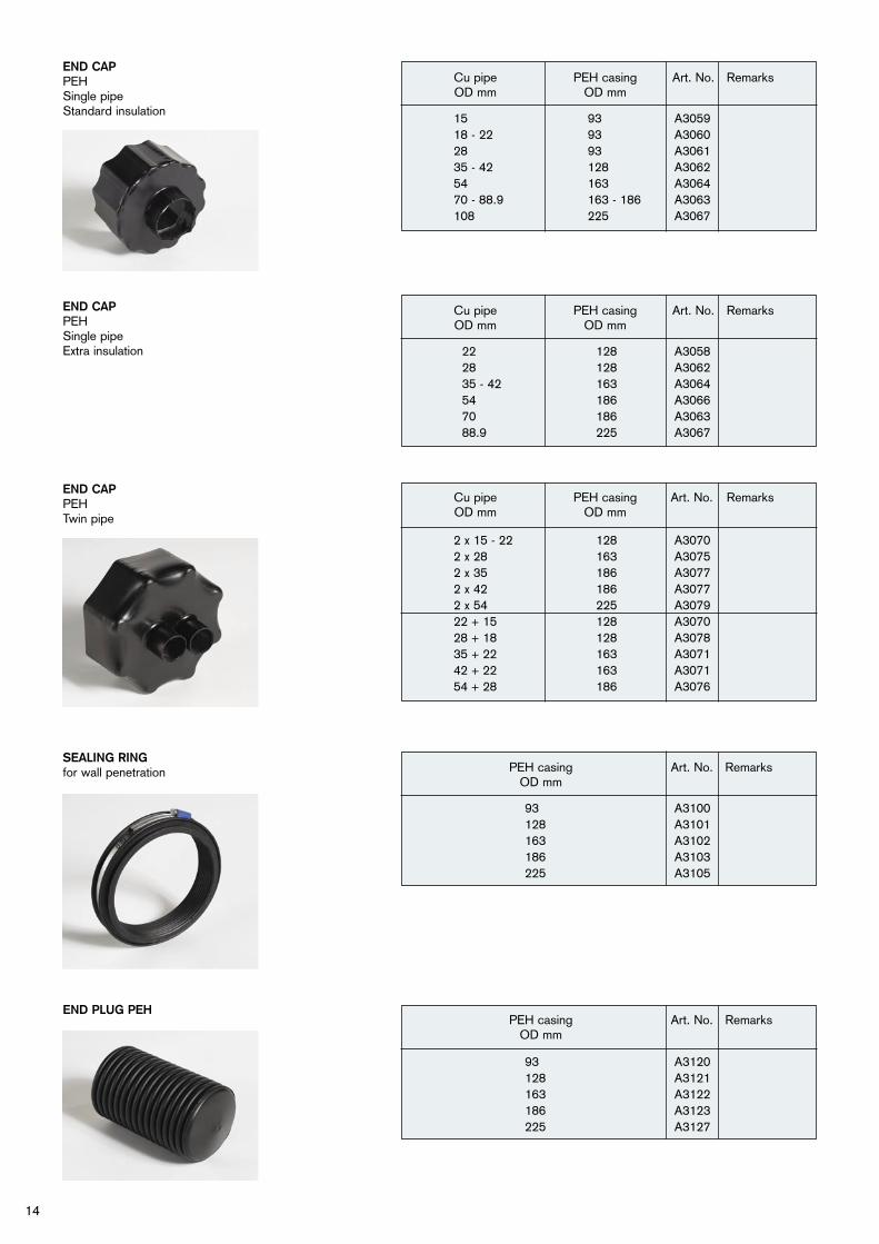
10. Shrink the sleeve using a long, soft propane gas flame, which is kept moving all the time. Take care not to damage the outer casing (don’t use a welding torch). First lightly heat the entire sleeve. Then shrink the sleeve from the middle. Begin from below. Then continue along the sleeve to its ends. To avoid overheating of the outer casing, turn the propane gas flame towards the middle of the shrink sleeve before the complete shrinking process takes place.
11. When the shrinking procedure has been finished, the shrink sleeve should grip the corrugated outer casing firmly. The mastic on the inside of the sleeve should have melted and seep out around the ends of the sleeve. It should be possible to see the outline of the joint. Press with a finger on the warm sleeve; the pressure mark should disappear as soon as you have removed your finger. When the joint has cooled down, it will have attained its full mechanical strength.
Cutting of pipes at site
If the pipes are cut at site, fit a centering plug and end cap on the bare pipe end. Shrink on the end cap with a gentle propane gas flame in the same way as for the shrink sleeve (see above). N.B. First shrink the part of the end cap that is intended to seal against the outer casing. Then shrink the end cap on to the copper pipe.

24
Pressure loss nomogram for Aquawarm heating and water pipes.
Maximum water velocity (allowed)Water pipes
Heating pipesBy risk of corrosion by velocity do not dimension the system with a higher speed than1.5 m/s.
Pre
ssu
re lo
ss (R
) per
met
re o
f p
ipes
.
Flow, l/s
Velo
city
, m/s
25
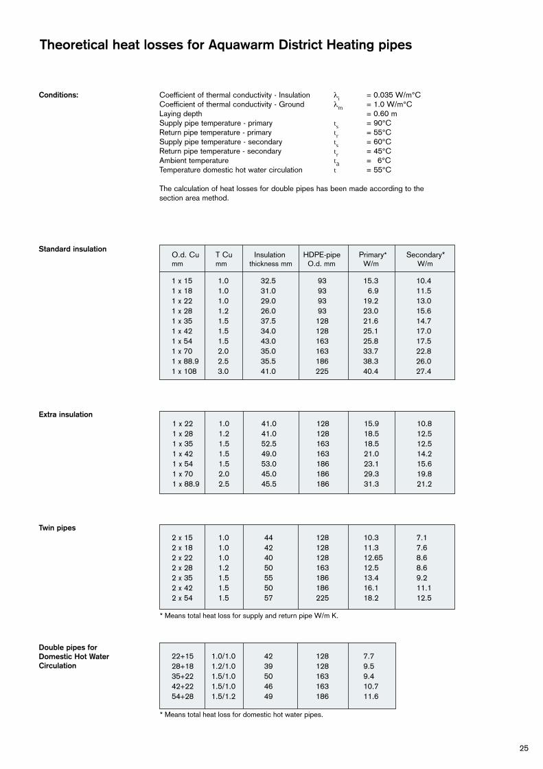
Theoretical heat losses for Aquawarm District Heating pipes
Conditions: Coefficient of thermal conductivity - Insulation λi = 0.035 W/m°C Coefficient of thermal conductivity - Ground λm = 1.0 W/m°C Laying depth = 0.60 m Supply pipe temperature - primary ts = 90°C Return pipe temperature - primary tr = 55°C Supply pipe temperature - secondary ts = 60°C Return pipe temperature - secondary tr = 45°C Ambient temperature ta = 6°C Temperature domestic hot water circulation t = 55°C The calculation of heat losses for double pipes has been made according to the section area method.
1 x 15 1.0 32.5 93 15.3 10.4 1 x 18 1.0 31.0 93 6.9 11.5 1 x 22 1.0 29.0 93 19.2 13.0 1 x 28 1.2 26.0 93 23.0 15.6 1 x 35 1.5 37.5 128 21.6 14.7 1 x 42 1.5 34.0 128 25.1 17.0 1 x 54 1.5 43.0 163 25.8 17.5 1 x 70 2.0 35.0 163 33.7 22.8 1 x 88.9 2.5 35.5 186 38.3 26.0 1 x 10⁸ 3.0 41.0 225 40.4 27.4
O.d. Cu T Cu Insulation HDPE-pipe Primary* Secondary*mm mm thickness mm O.d. mm W/m W/m
Standard insulation
Extra insulation
Twin pipes
Double pipes forDomestic Hot WaterCirculation
* Means total heat loss for supply and return pipe W/m K.
2 x 15 1.0 44 128 10.3 7.1 2 x 18 1.0 42 128 11.3 7.6 2 x 22 1.0 40 128 12.65 8.6 2 x 28 1.2 50 163 12.5 8.6 2 x 35 1.5 55 186 13.4 9.2 2 x 42 1.5 50 186 16.1 11.1 2 x 54 1.5 57 225 18.2 12.5
1 x 22 1.0 41.0 128 15.9 10.8 1 x 28 1.2 41.0 128 18.5 12.5 1 x 35 1.5 52.5 163 18.5 12.5 1 x 42 1.5 49.0 163 21.0 14.2 1 x 54 1.5 53.0 186 23.1 15.6 1 x 70 2.0 45.0 186 29.3 19.8 1 x 88.9 2.5 45.5 186 31.3 21.2
* Means total heat loss for domestic hot water pipes.
22+15 1.0/1.0 42 128 7.7 28+18 1.2/1.0 39 128 9.5 35+22 1.5/1.0 50 163 9.4 42+22 1.5/1.0 46 163 10.7 54+28 1.5/1.2 49 186 11.6

26
Notes

27
0512
. E.
ww
w.s
nap.
nu
Aquawarm is the original among flexible district heating and domestic hot water pipe systems. The system consists of soft copper pipes insulated with freon-free (CFC-free) glass wool and then enclosed in an outer casing of corrugated polyethy-lene. Aquawarm pipes are laid in a sinus-oidal pattern, which allows heat expan-sion of the copper pipes inside the insulation, while the outer casing in the ground does not move. This makes the entire system flexible, easy to install, reliable, environmentally friendly and economical. Why choose anything else than the original?
LOGSTOR Sverige AB Aquawarm
Box 85, SE-730 50 Skultuna, Sweden Phone +46-21-19 87 60
Fax +46-21-19 87 61www.aquawarm.com