the potential for extending the spectral range accessible to
TRANSCRIPT

TESLA-FEL 2004-05
The Potential for Extending the Spectral
Range Accessible to the European X-ray Free
Electron Laser in the Direction of Longer
Wavelengths
E.L. Saldin, E.A. Schneidmiller, and M.V. Yurkov
Deutsches Elektronen-Synchrotron (DESY), Hamburg, Germany
Abstract
The baseline specifications of European XFEL give a range of wavelengths be-tween 0.1 nm and 2 nm. This wavelength range at fixed electron beam energy of17.5 GeV can be covered by operating the SASE FEL with three undulators whichhave different period and tunable gap. A study of the potential for the extendingthe spectral range accessible to the XFEL in the direction of longer wavelengths ispresented. The extension of the wavelength range to 6 nm would cover the waterwindow in the VUV region, opening the facility to a new class of experiments. Thereare at least two possible sources of the VUV radiation associated with the X-rayFEL: the ”low (2.5 GeV) energy electron beam dedicated” and the ”17.5 GeV spentbeam parasitic” (or ”after-burner”) source modes. The second alternative, ”after-burner undulator” is the one we regard as the most favorable. It is possible to placean undulator as long as 80 meters after 2 nm undulator. Ultimately, VUV undulatorwould be able to deliver output power approaching 100 GW level. A beam from thisdevice could be run in pump-probe mode with the X-ray FEL.
26 May 2004


1 Introduction
Baseline design of present European XFEL project [1] assumed only stan-dard (SASE FEL) mode for production of radiation. Recent developmentsin the field of FEL physics and technology form a reliable basis for perspec-tive extensions of the XFEL facility. In [2] we proposed a concept of XFELlaboratory which will allow to implement perspective features from the verybeginning of operation. These extra features include delivery of X-ray pulsesin the attosecond regime, increasing of the FEL power (up to sub-TW level),simultaneous multi-undulator capability. A photon beam distribution systembased on movable multilayer X-ray mirrors can provide an efficient way toorganize a multi-user facility. Distribution of photons is achieved on the basisof pulse trains and it is possible to partition the photon beam among a fewtens independent beamlines thereby obtaining many users working in parallel.
The further development discussed in this paper concerns the expanded photonenergy range. The baseline specifications of European XFEL give a range ofwavelengths between 0.1 nm and 2 nm. It would be extremely interesting toextend this range into so-called ”water window”, i.e. the range between the K-Absorption edges of carbon and oxygen at 4.38 nm and 2.34 nm, respectively.This paper explores ways in which the wavelength of output radiation can beincreased well beyond the XFEL design. It will be shown that the flexibility ofthe XFEL design proposed in [2] allows a considerable expansion in reachableFEL photon energy in the direction of longer wavelengths. The wavelengthrange 0.1-6 nm at fixed electron beam energy of 17.5 GeV can be covered byoperating the SASE FEL with four undulators which have different period andtunable gap. In proposed (”after-burner”) scheme it will be possible to providein parallel hard (around 0.1 nm) and VUV radiation for two photon beamline.The extension of the wavelength range to 6 nm would cover the water window,opening the facility to a new class of experiments. For example, in some modesof operation, VUV FEL radiation could be used with X-ray FEL radiation todo pump-probe experiments with precise intervals between the sources.
2 VUV radiation from the European XFEL
This study will consider two possibilities: the first is based on ”electron switch-yard” technique. Figure 1 shows the schematic layout of the switchyard andthe undulator beamlines togeter with the accelerator. The electron beam (atenergy of 2.5 GeV) is extracted from the main linac and enters transport line,which guides it to the VUV undulator located near the experimental hall. Thebeam distribution system consists of two transport lines. The first beamline(2.5 GeV) directs one bunch train, coming to the ”water window” undulator.
1

Fig. 1. Schematic layout of the first possible strategy for VUV radiation. This schemeis based on the ”electron switchyard” technique
Fig. 2. Schematic layout of the most favorable strategy for VUV radiation. In thisscheme it will be possible to provide simultaneously hard X-ray and VUV radiationbeams (”after-burner” mode of operation)
The second beamline (17.5 GeV) takes every other bunch train and deliversit to X-ray undulators.
Figure 2 illustrates the second (baseline energy) option. This alternative is theone we regard as most favorable. The second option holds the energy at thebaseline value (17.5 GeV) and chooses the undulator period length to matchthe water window wavelengths. Tables 1 and 2 present optimized parameters ofundulator and FEL performance applied to ”water window” wavelength rangewith the electron energy of 2.5 GeV, and for the case of the maximum available
2
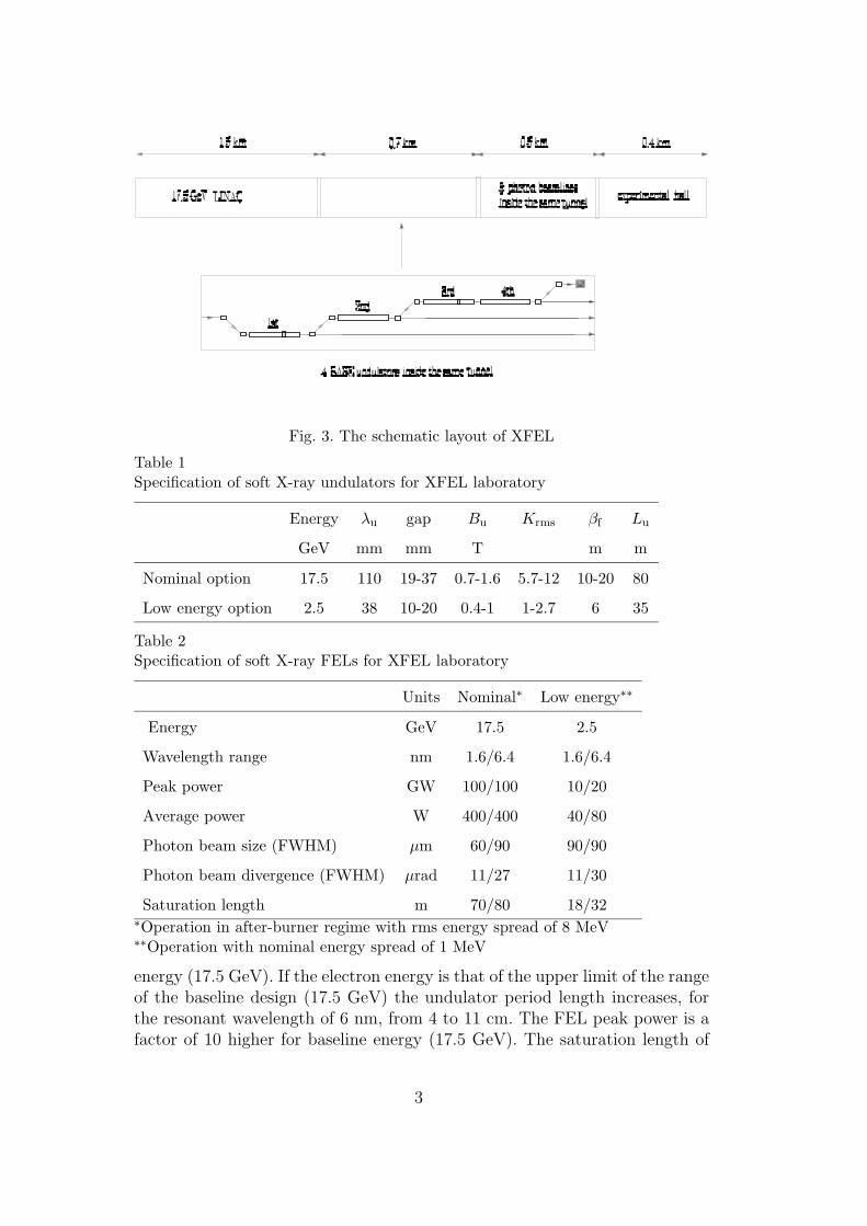
Fig. 3. The schematic layout of XFEL
Table 1Specification of soft X-ray undulators for XFEL laboratory
Energy λu gap Bu Krms βf Lu
GeV mm mm T m m
Nominal option 17.5 110 19-37 0.7-1.6 5.7-12 10-20 80
Low energy option 2.5 38 10-20 0.4-1 1-2.7 6 35
Table 2Specification of soft X-ray FELs for XFEL laboratory
Units Nominal∗ Low energy∗∗
Energy GeV 17.5 2.5
Wavelength range nm 1.6/6.4 1.6/6.4
Peak power GW 100/100 10/20
Average power W 400/400 40/80
Photon beam size (FWHM) µm 60/90 90/90
Photon beam divergence (FWHM) µrad 11/27 11/30
Saturation length m 70/80 18/32∗Operation in after-burner regime with rms energy spread of 8 MeV∗∗Operation with nominal energy spread of 1 MeV
energy (17.5 GeV). If the electron energy is that of the upper limit of the rangeof the baseline design (17.5 GeV) the undulator period length increases, forthe resonant wavelength of 6 nm, from 4 to 11 cm. The FEL peak power is afactor of 10 higher for baseline energy (17.5 GeV). The saturation length of
3

”water window” undulator at 17.5 GeV is 80 m, against the 30 m of the lowenergy undulator.
The second option is the simplest way to obtain VUV radiation from theEuropean XFEL. This is XFEL parasitic mode. All electron bunch trains willbe guided into one electron beamline and dump. The wavelength range 0.1-6nm at fixed electron beam energy of 17.5 GeV can be covered by operating theSASE FEL with four undulators which have different period and tunable gap.These SASE undulators can be placed behind each other assuming that thesubsequent undulator radiates at longer wavelength. It is a great advantagethat accelerator and electron beam transport line in this scheme operate atfixed parameters and that a fast ”electron switchyard” is not required. Inorder to avoid the need for a costly additional tunnels and shafts, the XFELsource is designed such that accelerator, all four SASE undulators, electronbeam line, and photon transport beamlines are installed inside the same (5 mdiameter) tunnel (see Fig. 3).
The electron beam transport line takes every bunch train and deliver it tothe first SASE undulator. The two bending magnets with a 10 mrad bendingangle provide a parallel shift of the beam axis by a distance of 0.5 m, thenthe electron beam reaches the entrance of the 2nd (3rd) SASE undulator.To bend the beam into the undulator, magnets operate in a DC mode. Thephoton beams of the 1st and 2nd (2nd and 3rd) SASE undulators have to beseparated by the distance of 2 m in the experimental hall, which is realizedby a deflection angle of about a mrad. After passing all four undulators, theelectrons are stopped in the beam dump.
Although the electron beam leaving the 1st SASE undulator has acquiredsome additional energy spread (8 MeV), it is still a good ”active medium” forthe 3rd (4th) SASE undulator at the end. In this scheme it will be possible toprovide in parallel hard (around 0.1 nm) and soft X-rays or VUV radiation fortwo photon beamlines (after-burner mode of operation). Normally if a SASEFEL operates in saturation, the quality of the electron beam is too bad forthe generation of SASE radiation in a subsequent undulator which is resonantat a few times longer wavelength. On the other hand, to operate XFEL at therequested radiation wavelengths (0.1 nm - 6 nm) four undulators are needed.The new method of SASE undulator-switching based on the rapid switchingof the SASE process proposed in the paper [2] is an attempt to get aroundthis obstacle (see Fig. 4).
All photon beamlines can be operated in parallel. Using electromagnetic phaseshifter in a SASE undulator it is possible to rapidly switch the FEL photonbeam from one SASE undulator beamline to the other, providing simultane-ous multi-undulator capability. Our approach focuses on the development ofelectromagnetic phase shifter embedded in the other components needed in-
4
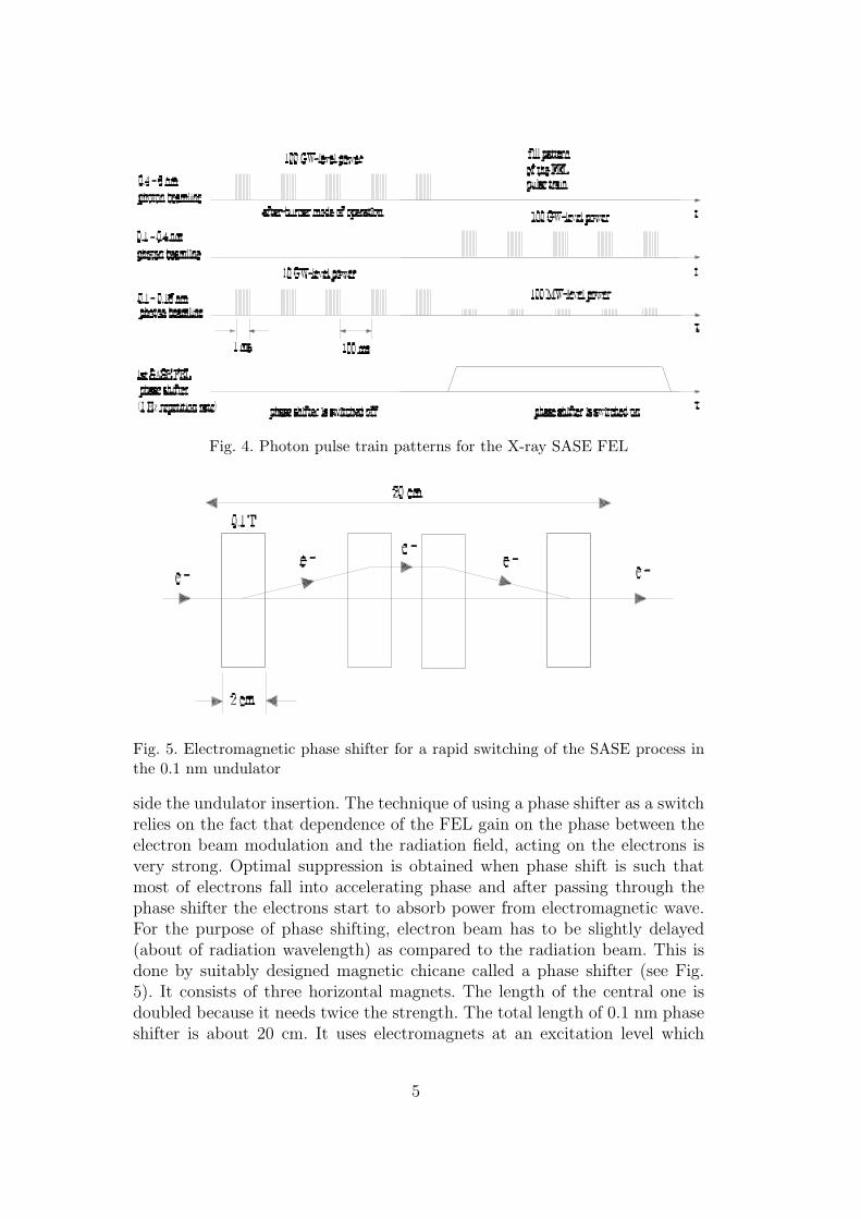
Fig. 4. Photon pulse train patterns for the X-ray SASE FEL
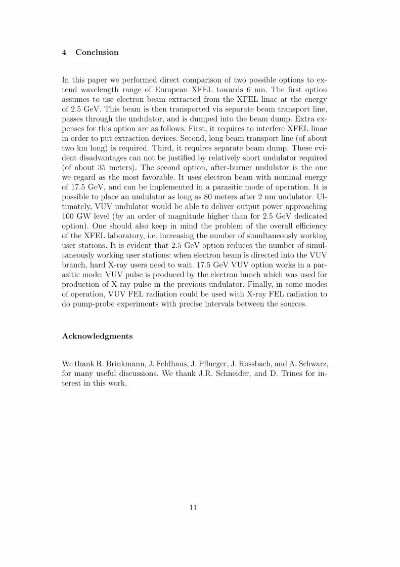
Fig. 5. Electromagnetic phase shifter for a rapid switching of the SASE process inthe 0.1 nm undulator
side the undulator insertion. The technique of using a phase shifter as a switchrelies on the fact that dependence of the FEL gain on the phase between theelectron beam modulation and the radiation field, acting on the electrons isvery strong. Optimal suppression is obtained when phase shift is such thatmost of electrons fall into accelerating phase and after passing through thephase shifter the electrons start to absorb power from electromagnetic wave.For the purpose of phase shifting, electron beam has to be slightly delayed(about of radiation wavelength) as compared to the radiation beam. This isdone by suitably designed magnetic chicane called a phase shifter (see Fig.5). It consists of three horizontal magnets. The length of the central one isdoubled because it needs twice the strength. The total length of 0.1 nm phaseshifter is about 20 cm. It uses electromagnets at an excitation level which
5

Fig. 6. Electromagnetic phase shifter for a switching of the SASE process in the 3rd(0.4-1.6 nm) undulator
Fig. 7. Installation of an phase shifter in the 3rd SASE undulator
is low enough, so that water cooling is not needed. For trapezoidal mode afrequency of 1 Hz is specified with a switching time of less than 10 ms. Thiskind of insertion device can be embedded between two neiboring undulatorsegments.
The electromagnetic phase shifter can also be configured for longer undulatorradiation wavelengths (see Fig. 6). The second phase shifter is a magneticchicane designed to introduce the electron beam delay needed to suppressSASE process in the 3rd undulator. It is also composed of the three low currentdipoles. Because of large delay, the total length of the second phase shifterincreases from 20 cm to 10 m. There is no problem to insert small (a fewcm long) dipole magnets at a 1 m spacing between two neiboring undulator
6

segments (see Fig. 7).
The photon beam transport system will deliver the FEL radiation to the exper-iments. It is desirable to perform experiments relatively far (at the distanceof several hundred meters) from the source. Therefore a long VUV beam-line is planned, with experimental hall beginning about 500 m from the 4th(VUV) undulator exit (see Fig. 3). One of the principal design goal of thephoton transport system is to contain the main photon beam entirely withinthe beamline vacuum pipe under all conditions. Because of its comparativelysmall divergence (about 30 µrad at 6 nm wavelength), this goal is not difficultto achieve without limiting the passage of the VUV FEL beam.
3 Operation of FEL source at longer wavelength
Present concept of an XFEL facility assumes to cover continuously wavelengthrange from 0.1 to 6 nm at a fixed (17.5 GeV) energy of the electron beam. Thisis achieved with four undulators installed in a series in one electron beamlineas illustrated in Fig. 2. Optimization of undulator parameters has been per-formed for the electron beam parameters presented in [1]: peak current 5 kA,rms normalized emittance 1.4 mm-mrad, and initial energy spread of 1 MeV.All undulators are planar, variable-gap devices with an identical mechanicaldesign. Optimized parameters of the undulator for both cases are presentedin Table 1. Calculations of the FEL characteristics are performed with time-dependent FEL simulation code FAST [3].
In this section, some examples will be given that shed light on the differencesbetween the undulator applied to the VUV wavelengths with the electronenergy of 2.5 GeV and an undulator that is modeled for the baseline energy17.5 GeV (after-burner undulator). The build-up of the radiation pulse energyalong the undulator is shown in Fig. 8. Requirements for FEL saturationat the shortest wavelength (1.6 nm) defines the undulator length: 35 m fordedicated 2.5 GeV option, and 80 m for 17.5 GeV after-burner option. Intensitydistributions of the radiation in the far and near diffraction zones are shown inFig. 9. Typical temporal and spectral structure of the radiation pulse from theVUV FEL operating at saturation are presented in Figs. 10 and 11. For bothoptions these structures are very similar, while peak power is much larger forthe after-burner option.
7

5 10 15 20 25 30 350
2
4
6
1.6 nm
6.4 nm
E = 2.5 GeV
E
rad [
mJ]
z [m]
30 40 50 60 70 80 900
5
10
15
20
25
6.4 nm
E = 17.5 GeV
Era
d [m
J]
z [m]
1.6 nm
Fig. 8. Energy in the radiation pulse versus undulator length. Left plot: low energyoption (2.5 GeV). Right plot: nominal energy option (17.5 GeV)
0 50 100 150 2000.0
0.2
0.4
0.6
0.8
1.0
|E(r
)/E(0
)|2
r [µm]
λ = 6.4 nm λ = 1.6 nm
E = 2.5 GeV
0 50 100 150 2000.0
0.2
0.4
0.6
0.8
1.0
λ = 6.4 nm λ = 1.6 nm
E = 17.5 GeV
|E(r
)/E(0
)|2
r [µm]
0 10 20 30 400.0
0.2
0.4
0.6
0.8
1.0
I(θ)
/I(0)
θ [µrad]
λ = 6.4 nm λ = 1.6 nm
E = 2.5 GeV
0 10 20 30 400.0
0.2
0.4
0.6
0.8
1.0
I(θ)
/I(0)
θ [µrad]
λ = 6.4 nm λ = 1.6 nm
E = 17.5 GeV
Fig. 9. Intensity distributions of the radiation in the near and far zone in saturationregime. Solid and dashed lines correspond to the radiation wavelength of 6.4 and1.6 nm, respectively. Left column: low energy option (2.5 GeV). Right column:nominal energy option (17.5 GeV)
8

50 100 150 200 250 300 3500
20
40
60
80
100
120E = 2.5 GeVλ = 6.4 nm
P [
GW
]
t [fs]
50 100 150 200 250 300 3500
100
200
300
400E = 17.5 GeVλ = 6.4 nm
P [
GW
]
t [fs]
200 210 220 230 240 2500
20
40
60
80
100
120E = 2.5 GeVλ = 6.4 nm
P [
GW
]
t [fs]
200 210 220 230 240 2500
100
200
300
400E = 17.5 GeVλ = 6.4 nm
P
[G
W]
t [fs]
-1.5 -1.0 -0.5 0.0 0.50
2
4
6
8E = 2.5 GeVλ = 6.4 nm
Nor
mal
ized
spe
ctru
m
∆ω/ω [%]-1.5 -1.0 -0.5 0.0 0.50
2
4
6E = 17.5 GeVλ = 6.4 nm
Nor
mal
ized
spe
ctru
m
∆ω/ω [%]
Fig. 10. Temporal and spectral structure of the radiation pulse in saturation regime.Radiation wavelength is 6.4 nm. Left column: low energy option (2.5 GeV). Rightcolumn: nominal energy option (17.5 GeV)
9

50 100 150 200 250 300 3500
10
20
30
40E = 2.5 GeVλ = 1.6 nm
P [
GW
]
t [fs]
50 100 150 200 250 300 3500
100
200
300
400E = 17.5 GeVλ = 1.6 nm
P [
GW
]
t [fs]
200 205 210 2150
10
20
30
40E = 2.5 GeVλ = 1.6 nm
P [
GW
]
t [fs]
200 205 210 2150
100
200
300
400E = 17.5 GeVλ = 1.6 nm
P
[G
W]
t [fs]
-1.0 -0.5 0.0 0.50
2
4
6
8
10E = 2.5 GeVλ = 1.6 nm
Nor
mal
ized
spe
ctru
m
∆ω/ω [%]
-1.0 -0.5 0.0 0.50
2
4
6
8
10E = 17.5 GeVλ = 1.6 nm
Nor
mal
ized
spe
ctru
m
∆ω/ω [%]
Fig. 11. Temporal and spectral structure of the radiation pulse in saturation regime.Radiation wavelength is 1.6 nm. Left column: low energy option (2.5 GeV). Rightcolumn: nominal energy option (17.5 GeV)
10
4 Conclusion
In this paper we performed direct comparison of two possible options to ex-tend wavelength range of European XFEL towards 6 nm. The first optionassumes to use electron beam extracted from the XFEL linac at the energyof 2.5 GeV. This beam is then transported via separate beam transport line,passes through the undulator, and is dumped into the beam dump. Extra ex-penses for this option are as follows. First, it requires to interfere XFEL linacin order to put extraction devices. Second, long beam transport line (of abouttwo km long) is required. Third, it requires separate beam dump. These evi-dent disadvantages can not be justified by relatively short undulator required(of about 35 meters). The second option, after-burner undulator is the onewe regard as the most favorable. It uses electron beam with nominal energyof 17.5 GeV, and can be implemented in a parasitic mode of operation. It ispossible to place an undulator as long as 80 meters after 2 nm undulator. Ul-timately, VUV undulator would be able to deliver output power approaching100 GW level (by an order of magnitude higher than for 2.5 GeV dedicatedoption). One should also keep in mind the problem of the overall efficiencyof the XFEL laboratory, i.e. increasing the number of simultaneously workinguser stations. It is evident that 2.5 GeV option reduces the number of simul-taneously working user stations: when electron beam is directed into the VUVbranch, hard X-ray users need to wait. 17.5 GeV VUV option works in a par-asitic mode: VUV pulse is produced by the electron bunch which was used forproduction of X-ray pulse in the previous undulator. Finally, in some modesof operation, VUV FEL radiation could be used with X-ray FEL radiation todo pump-probe experiments with precise intervals between the sources.
Acknowledgments
We thank R. Brinkmann, J. Feldhaus, J. Pflueger, J. Rossbach, and A. Schwarz,for many useful discussions. We thank J.R. Schneider, and D. Trines for in-terest in this work.
11

References
[1] P. Audebert et al., “TESLA XFEL: First stage of the X-ray laser laboratory –Technical design report (R. Brinkmann et al., Eds.)”, Preprint DESY 2002-167.
[2] E. L. Saldin, E. A. Schneidmiller and M. V. Yurkov, DESY Print TESLA FEL2004-02, DESY, Hamburg, 2004.
[3] E. L. Saldin, E. A. Schneidmiller and M. V. Yurkov, Nucl. Instrum. and MethodsA429(1999)233.
12