the rehabilitation of short span masonry arch highway bridges using near-surface reinforcement
TRANSCRIPT
This is a repository copy of The rehabilitation of short span masonry arch highway bridges using near-surface reinforcement.
White Rose Research Online URL for this paper:http://eprints.whiterose.ac.uk/42882/
Proceedings Paper:Garrity, SW (2010) The rehabilitation of short span masonry arch highway bridges using near-surface reinforcement. In: Bartlett, FM, (ed.) Proceedings of the 8th International Conference on Short and Medium Span Bridges. 8th International Conference on Short and Medium Span Bridges, 03 Aug 2010 - 06 Aug 2010, Niagara Falls, Ontario, Canada. Canadian Society for Civil Engineering , Montreal, Canada .
[email protected]://eprints.whiterose.ac.uk/
Reuse Unless indicated otherwise, fulltext items are protected by copyright with all rights reserved. The copyright exception in section 29 of the Copyright, Designs and Patents Act 1988 allows the making of a single copy solely for the purpose of non-commercial research or private study within the limits of fair dealing. The publisher or other rights-holder may allow further reproduction and re-use of this version - refer to the White Rose Research Online record for this item. Where records identify the publisher as the copyright holder, users can verify any specific terms of use on the publisher’s website.
Takedown If you consider content in White Rose Research Online to be in breach of UK law, please notify us by emailing [email protected] including the URL of the record and the reason for the withdrawal request.
Proceedings of 8th
International Conference on Short and Medium Span Bridges Niagara Falls, Canada 2010
075-1
THE REHABILITATION OF SHORT SPAN MASONRY ARCH HIGHWAY BRIDGES USING NEAR-SURFACE REINFORCEMEN T
Stephen W. Garrity University of Leeds, England, UK
ABSTRACT
Near-surface reinforcement has been developed as a minimum intervention, minimum disruption repair or strengthening technique for masonry arch bridges and similar structures. It involves installing small diameter stainless steel reinforcing bars, typically 6mm to 12mm in diameter, into pre-cut grooves or pre-drilled holes in the near-surface zones of the bridge that are likely to be subject to tensile stress. The principal aims of adding reinforcement are to improve flexural crack control, increase flexural and shear strength and to increase robustness and ductility. Typically the reinforcement is installed in the readily accessible surfaces, i.e. the intrados (or soffit) of the arch barrel and the exposed faces of the piers, abutments, spandrels, parapets and wingwalls. This paper summarises the results of a series of tests carried out on 2.95m span clay brick arches in the laboratory. The results of the research were used when designing the strengthening works for a single span arch bridge constructed in the late 18th century to span the Kennet and Avon Canal at Hungerford in Southern England. An innovative feature of this project, which is also briefly described in the paper, is that the longitudinal steel reinforcement was installed in holes that were pre-drilled into the soffit of the arch barrel to follow the line of the arch using a directed drilling technique. The strengthening scheme was given an Historic Bridge and Infrastructure Award by the Institution of Civil Engineers.
1. INTRODUCTION
Page (1993) has indicated that there may be in the order of 40,000 masonry arch highway bridges and 30,000 masonry arches carrying railways in the UK alone. Most of these were constructed between the second half of the eighteenth century and the beginning of the twentieth century during the development of the canal and the railway transportation networks. Many of these structures are now in need of repair or strengthening to meet the operational demands of the 21st century. A number of repair and strengthening measures have been developed for masonry arch bridges and other masonry structures (McKibbins et al 2006). One such minimum disruption, minimum intervention technique is near-surface reinforcement or “retro-reinforcement” (Garrity 1994, Garrity 1995a). This involves installing small diameter stainless steel reinforcing bars, typically 6mm to 12mm in diameter, into pre-cut grooves or pre-drilled holes in the near-surface zones of masonry that are likely to be subject to tensile stress. The principal aims of adding reinforcement are to improve flexural crack control, increase flexural and shear strength and to increase robustness and ductility. In the case of a masonry arch bridge, reinforcement is installed in the readily accessible surfaces, i.e. the intrados (or soffit) of the arch barrel and the exposed faces of the piers, abutments, spandrels, parapets and wingwalls. To date, experimental studies of retro-reinforced arches have been limited to the small scale testing of single ring arches (Garrity 1995b), very small-scale tests in a centrifuge (Baralos 2002) or to tests on full-scale multi-ring arches in which very few parameters were varied (Sumon 1997, 2005). As far as the author is aware, the research summarised in this paper is the first in which the mortar type and the amounts of longitudinal and inter-ring (shear) reinforcement have been varied within a large-scale test programme.

075-2
2. THE TEST ARCHES
The testing was carried out in two phases with four arches tested per phase. The phase I tests (arches 1 to 4) were carried out to investigate the influence of longitudinal reinforcement on the structural behaviour. As will be explained later, ring separation was found to be a cause of premature failure in some of the phase I tests. As a result, the phase II tests (arches 5 to 8) were carried out to assess the performance of different arrangements of shear reinforcement to prevent ring separation. All eight arches were of the same form of construction. Each had a segmental profile with a clear span of 2.95m; a rise of 0.77m; a width of 1.34m and consisted of 3 rings of stretcher-bonded brickwork with a total nominal thickness of 328mm. All the arches were built onto removable timber centring spanning between 328mm thick brickwork abutments. These were built onto a self-straining structural steelwork test rig which was set up on the structural strong floor of the structures laboratory. Two identical rigs were used in the testing; each rig was wide enough to accommodate two arches. Hence, in each phase of testing, four arches were constructed on two test rigs. This had the advantage of allowing four arches to be built at the same time using the same bricklayer thereby minimising any variations in the standard of workmanship. Typical details of the arches and the steelwork test rig are shown in Figure 1. All the arches were constructed from solid clay bricks with the following average properties: a density of 2268 kg/m3; a compressive strength of 133.8 N/mm2; an initial rate of suction of 0.5g/m2.min and a water absorption of 4.1%. These values are based on the results from tests carried out on a randomly sampled batch of 20 bricks. These bricks were used to replicate the very high strength bricks that were often used in the UK in the 1800s (and later) for the arch barrels of railway bridges.
Figure 1. Typical test arch details showing the longitudinal reinforcement (all dimensions are in millimetres).
Stainless steel reinforcement grouted into 20mm wide x 60mm deep grooves cut into arch intrados @ 225 mm centres
328
1340
TYPICAL SECTION THROUGH BARREL
Stainless steel longitudinal reinforcement
600 mm anchorage length
3 ring, 328 mm thick clay brick arch barrel
328 mm thick brick abutment
1100
770 (rise)
2950 clear span
Structural steelwork test rig
Structural steelwork test rig
Laboratory floor
Full width line load applied at ¼ span – see load frame details in Figure 2
075-3
3. PHASE I TEST ARCHES
Three of the four phase I arches (numbers 2, 3 and 4) were reinforced with different amounts of 6mm diameter stainless steel longitudinal reinforcement. Arch 1 was built as an unreinforced experimental control. In arches 2 and 3, the longitudinal reinforcing bars, each fitted with twisted wire spacers, were installed in 6 no. 60mm deep x 20mm wide grooves cut into the arch intrados with a double-bladed circular saw. The grooves were spaced transversely across the arch at 225mm centres. Each groove was filled with a thixotropic cementitious grout, the aim being to ensure a full composite connection between the reinforcement and the arch. Arch 2 was reinforced with a total of 12 no. 6mm diameter stainless steel reinforcing bars distributed in pairs in each of the 6 grooves. Arch 3 was reinforced with only 6 bars (i.e. half the reinforcement of arch 2), with only one bar inserted in each groove. In arch 4, pairs of 6mm diameter bars were inserted into 20mm diameter holes that were drilled into the arch using a flexible drive drill. The flexible drive allowed each hole to be “steered” by the operator so that it remained approximately parallel with the arch intrados (or soffit). Arch 4 was reinforced in this manner as a trial to demonstrate that reinforcement could be installed in holes that are not visible on the underside of a bridge as an alternative to grooves which may be visually unacceptable to some bridge owners. As the phase I tests were carried out, in part, as a pilot study, no close control was exerted on the batching of the mortar. This was specified as a 1:4½ (OPC:sand) mix to give fairly high early strengths to allow the arches to be strengthened and then tested without too much delay.
4. PHASE II TEST ARCHES
As explained later, ring separation, i.e. inter-ring shear failure, was found to be a cause of premature failure in some of the phase I tests. As a result, the phase II tests were carried out to investigate different forms of inter-ring shear connection. All the phase II arches (numbers 5 to 8, inclusive) had the same longitudinal reinforcement as arch 2, namely a total of 12 no. 6mm diameter stainless steel reinforcing bars distributed in pairs in 6 no. grooves spaced transversely across the arch at 225mm centres. Arches 6 and 7 were fitted with 10mm and 16mm diameter U-bar shear reinforcement spaced every 300mm (longitudinally and transversely), respectively. Arch 8 was fitted with 10mm diameter straight radial dowel bars spaced every 225mm (longitudinally and transversely). Arch 5 was the experimental control; it was longitudinally reinforced but not fitted with any shear reinforcement. All the reinforcement was inserted in pre-drilled grooves (in the case of the longitudinal reinforcement) or holes (in the case of the shear reinforcement) and the space between the brickwork and the reinforcement was filled with a thixotropic cementitious grout. The Phase II arches were built using a 1:9 OPC:sand mortar and with much closer control of the weigh batching and mixing than was the case with the phase I arches. A lower strength mortar than that used for the phase I tests was specified to increase the likelihood of ring separation during testing.
5. TEST ARRANGEMENT
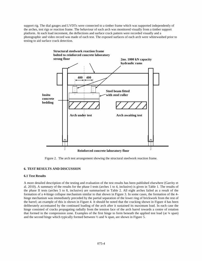
Each arch was subjected to a full-width vertical line load applied at quarter span, as shown previously in Figure 1. The load was applied incrementally until collapse, using two 1000kN capacity hydraulic rams controlled from the same pump. The point loads from the two rams were applied to each arch via a steel spreader beam with a 32mm diameter steel roller welded to its bottom flange. The load from the beam and roller arrangement was applied through an in-situ concrete bed cast on to the arch extrados to provide a level surface. The reaction to the applied load was provided by a steel frame which was bolted to the reinforced concrete strong floor of the laboratory, as shown in Figure 2. Direct strains were measured on the surfaces of the reinforcement under the applied load (at quarter span) and on the steel anchored into the abutment remote from the applied load. In addition, vertical deflections of the barrel extrados were measured using rows of dial gauges and linear variable differential transformers (LVDTs) controlled and recorded by a multi-channel data logger. Lateral deflection of the steel support rigs was measured using a series of dial gauges. In the first phase of tests it was found that the steel support rig deflected laterally, with increasing test load applied to the arches, by up to 8mm. This was considered acceptable and was thought to replicate the lateral deflection of the abutments of a real bridge at or close to collapse. Accordingly, no attempt was made to stiffen the
075-4
support rig. The dial gauges and LVDTs were connected to a timber frame which was supported independently of the arches, test rigs or reaction frame. The behaviour of each arch was monitored visually from a timber support platform. At each load increment, the deflections and surface crack pattern were recorded visually and a photographic and video record was made of each test. The exposed surfaces of each arch were whitewashed prior to testing to aid surface crack detection.
Figure 2. The arch test arrangement showing the structural steelwork reaction frame.
6. TEST RESULTS AND DISCUSSION
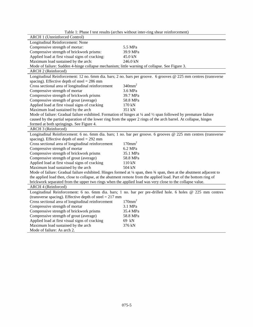
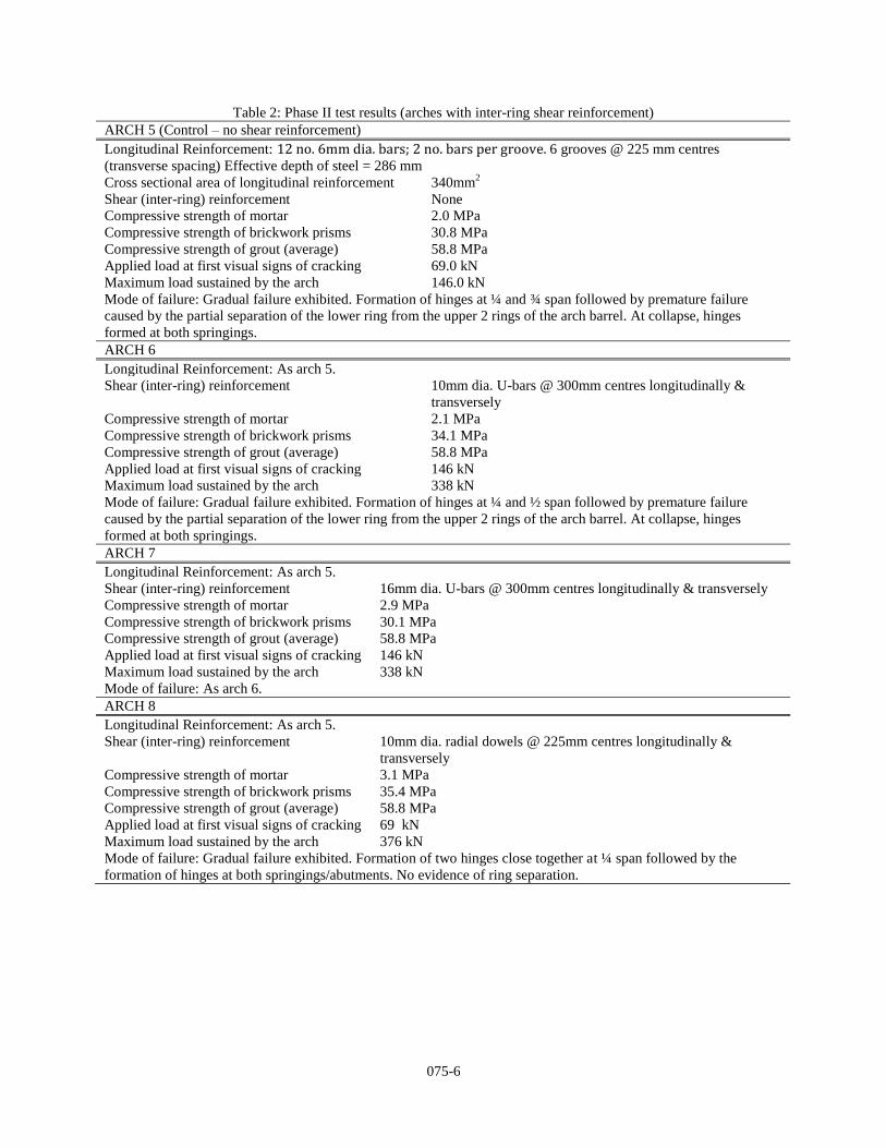
6.1 Test Results
A more detailed description of the testing and evaluation of the test results has been published elsewhere (Garrity et al. 2010). A summary of the results for the phase I tests (arches 1 to 4, inclusive) is given in Table 1. The results of the phase II tests (arches 5 to 8, inclusive) are summarised in Table 2. All eight arches failed as a result of the formation of a 4-hinge collapse mechanism similar to that shown in Figure 3. In some cases, the formation of the 4-hinge mechanism was immediately preceded by the partial separation of the lower ring of brickwork from the rest of the barrel; an example of this is shown in Figure 4. It should be noted that the cracking shown in Figure 4 has been deliberately accentuated by the continued loading of the arch after it sustained its maximum load. In each case the hinge consisted of cracks propagating radially from the tension face of the arch barrel towards a centre of rotation that formed in the compression zone. Examples of the first hinge to form beneath the applied test load (at ¼ span) and the second hinge which typically formed between ½ and ¾ span, are shown in Figure 5.
Reinforced concrete laboratory floor
400 400
Structural steelwork reaction frame bolted to reinforced concrete laboratory strong floor 2no. 1000 kN capacity
hydraulic rams
Insitu concrete bedding
Steel beam fitted with steel roller
Arch under test Arch awaiting test
075-5
Table 1: Phase I test results (arches without inter-ring shear reinforcement) ARCH 1 (Unreinforced Control) Longitudinal Reinforcement: None Compressive strength of mortar: 5.5 MPa Compressive strength of brickwork prisms: 39.9 MPa Applied load at first visual signs of cracking: 45.0 kN Maximum load sustained by the arch: 246.0 kN Mode of failure: Sudden 4-hinge collapse mechanism; little warning of collapse. See Figure 3. ARCH 2 (Reinforced) Longitudinal Reinforcement: 12 no. 6mm dia. bars; 2 no. bars per groove. 6 grooves @ 225 mm centres (transverse spacing). Effective depth of steel = 286 mm Cross sectional area of longitudinal reinforcement 340mm2 Compressive strength of mortar 3.6 MPa Compressive strength of brickwork prisms 39.7 MPa Compressive strength of grout (average) 58.8 MPa Applied load at first visual signs of cracking 170 kN Maximum load sustained by the arch 351 kN Mode of failure: Gradual failure exhibited. Formation of hinges at ¼ and ½ span followed by premature failure caused by the partial separation of the lower ring from the upper 2 rings of the arch barrel. At collapse, hinges formed at both springings. See Figure 4. ARCH 3 (Reinforced) Longitudinal Reinforcement: 6 no. 6mm dia. bars; 1 no. bar per groove. 6 grooves @ 225 mm centres (transverse spacing). Effective depth of steel = 292 mm Cross sectional area of longitudinal reinforcement 170mm2 Compressive strength of mortar 6.2 MPa Compressive strength of brickwork prisms 35.1 MPa Compressive strength of grout (average) 58.8 MPa Applied load at first visual signs of cracking 110 kN Maximum load sustained by the arch 504 kN Mode of failure: Gradual failure exhibited. Hinges formed at ¼ span, then ¾ span, then at the abutment adjacent to the applied load then, close to collapse, at the abutment remote from the applied load. Part of the bottom ring of brickwork separated from the upper two rings when the applied load was very close to the collapse value. ARCH 4 (Reinforced) Longitudinal Reinforcement: 6 no. 6mm dia. bars; 1 no. bar per pre-drilled hole. 6 holes @ 225 mm centres (transverse spacing). Effective depth of steel = 217 mm Cross sectional area of longitudinal reinforcement 170mm2 Compressive strength of mortar 3.1 MPa Compressive strength of brickwork prisms 35.4 MPa Compressive strength of grout (average) 58.8 MPa Applied load at first visual signs of cracking 69 kN Maximum load sustained by the arch 376 kN Mode of failure: As arch 2.
075-6
Table 2: Phase II test results (arches with inter-ring shear reinforcement) ARCH 5 (Control – no shear reinforcement) Longitudinal Reinforcement: 12 no. 6mm dia. bars; 2 no. bars per groove. 6 grooves @ 225 mm centres (transverse spacing) Effective depth of steel = 286 mm Cross sectional area of longitudinal reinforcement 340mm2 Shear (inter-ring) reinforcement None Compressive strength of mortar 2.0 MPa Compressive strength of brickwork prisms 30.8 MPa Compressive strength of grout (average) 58.8 MPa Applied load at first visual signs of cracking 69.0 kN Maximum load sustained by the arch 146.0 kN Mode of failure: Gradual failure exhibited. Formation of hinges at ¼ and ¾ span followed by premature failure caused by the partial separation of the lower ring from the upper 2 rings of the arch barrel. At collapse, hinges formed at both springings. ARCH 6 Longitudinal Reinforcement: As arch 5. Shear (inter-ring) reinforcement 10mm dia. U-bars @ 300mm centres longitudinally &
transversely Compressive strength of mortar 2.1 MPa Compressive strength of brickwork prisms 34.1 MPa Compressive strength of grout (average) 58.8 MPa Applied load at first visual signs of cracking 146 kN Maximum load sustained by the arch 338 kN Mode of failure: Gradual failure exhibited. Formation of hinges at ¼ and ½ span followed by premature failure caused by the partial separation of the lower ring from the upper 2 rings of the arch barrel. At collapse, hinges formed at both springings. ARCH 7 Longitudinal Reinforcement: As arch 5. Shear (inter-ring) reinforcement 16mm dia. U-bars @ 300mm centres longitudinally & transversely Compressive strength of mortar 2.9 MPa Compressive strength of brickwork prisms 30.1 MPa Compressive strength of grout (average) 58.8 MPa Applied load at first visual signs of cracking 146 kN Maximum load sustained by the arch 338 kN Mode of failure: As arch 6. ARCH 8 Longitudinal Reinforcement: As arch 5. Shear (inter-ring) reinforcement 10mm dia. radial dowels @ 225mm centres longitudinally &
transversely Compressive strength of mortar 3.1 MPa Compressive strength of brickwork prisms 35.4 MPa Compressive strength of grout (average) 58.8 MPa Applied load at first visual signs of cracking 69 kN Maximum load sustained by the arch 376 kN Mode of failure: Gradual failure exhibited. Formation of two hinges close together at ¼ span followed by the formation of hinges at both springings/abutments. No evidence of ring separation.

075-7
Figure 3. Arch 1 (unreinforced control) showing the 4-hinge collapse mechanism.
Figure 4. A reinforced arch (arch 2) without shear reinforcement showing premature
partial ring separation and a 4-hinge collapse mechanism.
Figure 5. Hinges forming in the arch barrel at ¼ span (left) and ¾ span (right).
075-8
6.2 Principal Findings from the Tests
The main findings from the tests briefly described in this paper are: a). All the retro-reinforced arches behaved as reinforced brickwork structures; the retro-fitted reinforcement
behaved compositely with the brickwork in all cases. There was no evidence of any de-bonding failures at either the grout/brickwork or grout/reinforcement interfaces.
b). Longitudinal reinforcement installed in the arch intrados close to the surface was found to delay the onset of first cracking and to increase the load carrying capacity. This confirms the findings from the small-scale model arch tests previously carried out by the author (Garrity 1995b).
c). Longitudinal reinforcement was found to be effective as a strengthening measure whether installed in pre-cut grooves or pre-drilled holes. Reinforcement installed in grooves is more structurally efficient because of the larger effective depth, but bars installed in pre-drilled holes are less visually intrusive.
d). The mortar strength had a significant influence on the performance of the reinforced arches. Those constructed using weaker mortar (compressive strength of the order of 3 N/mm2) were found to be more likely to develop ring separation and to fail at lower loads than those built of stronger mortar (compressive strength of the order of 6 N/mm2).
e). Radial dowel reinforcement, installed through the full depth of the arch ring, was found to be more effective at preventing an inter-ring shear failure (ring separation) than U-bars and was easier to install.
The research results were used when developing the design of the strengthening works for a number of short single span masonry arch highway bridges in the UK. Of particular note is the strengthening of Hungerford Canal Bridge which is described below. The author acted as a specialist adviser to the contractor, Bersche-Rolt Limited, in the early stages of the design then carried out an independent check of the proposed strengthening works for the client.
7. THE STRENGTHENING OF HUNGERFORD CANAL BRIDGE, UK
7.1 Background
Hungerford canal bridge is a grade II listed single span clay brick arch structure dating from c.1798. It has a clear span of approximately 7.1m measured between the exposed faces of the brickwork abutments. The 330mm thick arch barrel has an elliptical profile and a maximum rise of 2.35m; it supports fill with an average depth of 460mm at the crown. The wingwalls, pilasters, spandrel walls and parapets are all of solid brickwork construction. The grade II listing means that the bridge has been included on a statutory list of structures in England that are designated to be of special architectural or historical interest “which warrant every effort being made to preserve them” (DCMS 2005). The bridge carries the busy A338 highway across the Kennet and Avon Canal and is located in the county of Berkshire in Southern England. The highway is one of the main links between the small town of Hungerford and the regional M4 motorway (or freeway) which connects London and South Wales. Although the canal fell into disrepair and many sections of it were closed by the 1950s, with the formation of British Waterways Board in 1962 the canal was gradually restored and it was re-opened fully to traffic in 2003. It is now used extensively by tourists who not only use the waterway but also walk or cycle along its towpath. The canal is also used by a small amount of commercial traffic. An assessment of the load carrying capacity of the bridge indicated that it was in need of strengthening to meet current operating standards. In addition, many parts of the exposed brickwork were found to be suffering from frost damage and needed to be replaced. The consulting engineer appointed by the bridge owner to investigate alternative strengthening methods selected near-surface reinforcement because the highway could remain open to traffic at all times and there would be minimal disruption to the residential properties and small businesses located close to the bridge, the nearest being about 5m away from one of the wingwalls. In addition, the contractor proposed to drill into the brickwork and install all the reinforcement from a pontoon floating on the canal. By temporarily suspending construction operations and moving the pontoon from underneath the bridge, canal traffic could pass beneath the bridge. Further details of this project have been reported by McKibbins et al (2006).
075-9
7.2 Design and Construction of the Strengthening Works
7.2.1 Design Philosophy
With masonry arch bridges and similar structures, any strengthening measures that are designed solely to increase strength are unlikely to represent good value for money. Exposure to longer-term risks to the continued well-being of the bridge such as differential settlement, localised scour and increased weathering effects should also be considered by the designer as well as the need to minimise any disruption to the bridge users and local people. Taking into account these requirements and the listed status of the bridge, it was considered essential to design the strengthening works for Hungerford Canal Bridge to: a). Increase the load-carrying capacity of the arch barrel to meet modern operational requirements defined by the
UK Highways Agency; b). Minimise any disruption to the canal users, the highway users, local residents and businesses; c). Minimise the risk of any future damage to or deterioration of the bridge caused by the strengthening works; d). Integrate increased robustness, durability and resilience into the design; e). Develop a strengthening proposal that would respect the architectural and historical heritage of the bridge. These requirements were met by installing an array of comparatively small diameter stainless steel reinforcing bars in the longitudinal and transverse directions in the arch barrel. Such reinforcement was installed from the underside of the bridge, as briefly described in 7.1. The distance between adjacent reinforcing bars was kept in the range 300mm to 400mm to reduce the likelihood of overstressing the original brickwork and to produce, in effect, a mesh of reinforcement. This can be regarded in a similar vein to the crack control and distribution steel provided in most reinforced concrete slabs. In addition, radial dowels were installed through the full thickness of the arch barrel to reduce the risk of ring separation. Details of the transverse, longitudinal and radial dowel reinforcement are summarised in 7.2.2, below. The longitudinal (main) reinforcement was designed using a limit state approach with partial factors of safety and loads defined by the UK Highways Agency. The critical bending moments used in the structural design were obtained from a plastic analysis of the arch barrel. The analysis was based on the 4-hinge mechanism method first proposed by Heyman (1980) for unreinforced arches subjected to a line load representing the axle of a vehicle. In the author’s experience, with short span masonry arch bridges it is usually a single axle load which tends to be critical in the design of strengthening measures rather than combinations of two or more axles where there is usually a measure of relief against sway behaviour. A 4-hinge mechanism analysis was considered to be appropriate given the behaviour of the arches tested in the laboratory, described earlier in this paper. The effect of the reinforcement was taken into account in the mechanism analysis by including the moment capacity of the reinforced masonry arch barrel at the two hinges where tensile stress was expected to occur in the arch intrados (soffit). At the other two hinge locations tensile stress was expected to occur in the extrados (upper surface) where there was no reinforcement to increase the moment capacity. In the analysis, a single vertical line load was applied to the arch barrel through the fill. Two of the hinge positions were fixed at each springing and the other two hinge positions were systematically varied to yield the lowest value of applied load. This value is defined as the collapse load by the upper bound theorem of plasticity on which the analysis was based. The amount of steel reinforcement and the moment capacity of the two hinges were increased to provide a collapse load that was at least equal to the design ultimate axle load. It should be noted that, following the design procedure for reinforced masonry elements in BS 5628 (BSI 2005), the moment capacity of an under-reinforced section was used to minimise the risk of a sudden compressive failure of the brickwork. Although the compressive strength of the brickwork of Hungerford bridge was only of the order of 3 N/mm2, the arch barrel was sufficiently thick for even a fairly small area of steel reinforcement to provide a significant increase in the moment capacity of the arch barrel without risking a compression failure.
7.2.2 Reinforcement Details
Transverse reinforcement. Typically with retro-reinforcement, stainless steel bars are grouted into pre-drilled holes across the full width of the arch barrel. This reinforcement provides improved lateral load distribution not only of concentrated wheel load effects but also any future differential settlement or loss of support from the ground due to
075-10
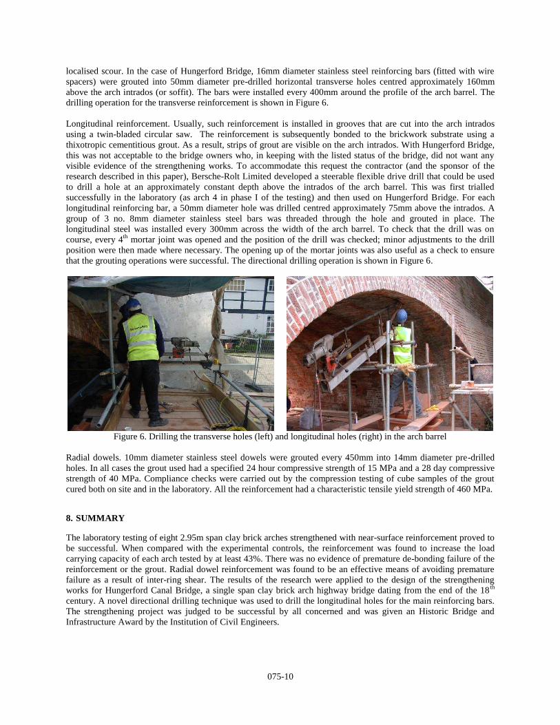
localised scour. In the case of Hungerford Bridge, 16mm diameter stainless steel reinforcing bars (fitted with wire spacers) were grouted into 50mm diameter pre-drilled horizontal transverse holes centred approximately 160mm above the arch intrados (or soffit). The bars were installed every 400mm around the profile of the arch barrel. The drilling operation for the transverse reinforcement is shown in Figure 6. Longitudinal reinforcement. Usually, such reinforcement is installed in grooves that are cut into the arch intrados using a twin-bladed circular saw. The reinforcement is subsequently bonded to the brickwork substrate using a thixotropic cementitious grout. As a result, strips of grout are visible on the arch intrados. With Hungerford Bridge, this was not acceptable to the bridge owners who, in keeping with the listed status of the bridge, did not want any visible evidence of the strengthening works. To accommodate this request the contractor (and the sponsor of the research described in this paper), Bersche-Rolt Limited developed a steerable flexible drive drill that could be used to drill a hole at an approximately constant depth above the intrados of the arch barrel. This was first trialled successfully in the laboratory (as arch 4 in phase I of the testing) and then used on Hungerford Bridge. For each longitudinal reinforcing bar, a 50mm diameter hole was drilled centred approximately 75mm above the intrados. A group of 3 no. 8mm diameter stainless steel bars was threaded through the hole and grouted in place. The longitudinal steel was installed every 300mm across the width of the arch barrel. To check that the drill was on course, every 4th mortar joint was opened and the position of the drill was checked; minor adjustments to the drill position were then made where necessary. The opening up of the mortar joints was also useful as a check to ensure that the grouting operations were successful. The directional drilling operation is shown in Figure 6.
Figure 6. Drilling the transverse holes (left) and longitudinal holes (right) in the arch barrel
Radial dowels. 10mm diameter stainless steel dowels were grouted every 450mm into 14mm diameter pre-drilled holes. In all cases the grout used had a specified 24 hour compressive strength of 15 MPa and a 28 day compressive strength of 40 MPa. Compliance checks were carried out by the compression testing of cube samples of the grout cured both on site and in the laboratory. All the reinforcement had a characteristic tensile yield strength of 460 MPa.
8. SUMMARY
The laboratory testing of eight 2.95m span clay brick arches strengthened with near-surface reinforcement proved to be successful. When compared with the experimental controls, the reinforcement was found to increase the load carrying capacity of each arch tested by at least 43%. There was no evidence of premature de-bonding failure of the reinforcement or the grout. Radial dowel reinforcement was found to be an effective means of avoiding premature failure as a result of inter-ring shear. The results of the research were applied to the design of the strengthening works for Hungerford Canal Bridge, a single span clay brick arch highway bridge dating from the end of the 18th century. A novel directional drilling technique was used to drill the longitudinal holes for the main reinforcing bars. The strengthening project was judged to be successful by all concerned and was given an Historic Bridge and Infrastructure Award by the Institution of Civil Engineers.
075-11
9. ACKNOWLEDGEMENTS
All the experimental work was carried out by the author when he was a practising consulting engineer and Visiting Professor at the University of Bradford. Thanks are due to all the structures laboratory staff and to Drs Y. Chen and A.F.Ashour for their support. The work described in this paper is part of a larger research project funded by Bersche-Rolt Limited of Stream House, Heron’s Ghyll, Uckfield, East Sussex, England, UK. Thanks are due to Bersche-Rolt Limited for their support, encouragement and commitment to investing in research.
10. REFERENCES
Baralos, P. 2002. The small scale modelling of repair techniques for masonry arch bridges using a geotechnical centrifuge. PhD thesis, Cardiff University, Wales, UK.
British Standards Institution. 2005. “Code of practice for the use of masonry - Part 2: Structural use of reinforced and prestressed masonry”, BS 5628. British Standards Institution, London, England, UK.
Department for Culture, Media and Sport (DCMS). 2005. “Principles of selection for listing buildings: planning policy guidance note 15”. Department for Culture, Media and Sport, Architecture and Historic Environment Division, Office of the Deputy Prime Minister, London, England, UK.
Garrity, S.W. 1994, Retro-reinforcement of existing masonry structures. 10th International Brick & Block Masonry Conference, Calgary, Masonry Council of Canada/University of Calgary, Canada: 469-478.
Garrity, S.W. 1995a. Retro-reinforcement - a proposed repair system for masonry arch bridges. In Arch Bridges (Ed. C.Melbourne), Thomas Telford Services Ltd, London, England, UK: 557-566.
Garrity, S.W. 1995b. Testing of small scale masonry arch bridges with surface reinforcement. 6th International Conference on Structural Faults and Repair, Engineering Technics Press, Edinburgh, Scotland, UK: (1), 409 - 418.
Garrity, S.W., Ashour, A.F. and Chen, Y. 2010. An experimental investigation of retro-reinforced clay brick arches. 8th International Masonry Conference, Dresden, Germany, International Masonry Society, Surrey, England, UK, paper ref. 206 in CD-ROM proceedings.
Heyman, J. 1980. The estimation of the strength of masonry arches. Proceedings of the Institution of Civil Engineers, Part 2, Vol. 69 (December): 921-937.
McKibbins, L.D., Melbourne, C., Sawar, N, and Sicilia Gaillard, C. 2006. “Masonry arch bridges: conditional appraisal and remedial treatment”. CIRIA Report C656, Construction Industry Research and Information Association, London, England, UK.
Page J. 1993. State-of-the-art review: masonry arch bridges. Transport Research Laboratory, Department of Transport, Her Majesty’s Stationery Office, London, England, UK.
Sumon, S.K. 1998. Repair and strengthening of five full scale masonry arch bridges, in Arch Bridges: history, analysis, assessment, maintenance and repair (Ed. A. Sinopoli). Balkema, Rotterdam, The Netherlands: 407-415.
Sumon, S.K. 2005. Innovative retrofitted reinforcement techniques for masonry arch bridges. Proceedings of the Institution of Civil Engineers, Bridge Engineering, 158 (BE3 September): 91-99.