the role of flow in g reen chemistr y and engineering
TRANSCRIPT
The role of flow in green chemistry and engineering
The MIT Faculty has made this article openly available. Please share how this access benefits you. Your story matters.
Citation Newman, Stephen G., and Klavs F. Jensen. “The Role of Flow inGreen Chemistry and Engineering.” Green Chemistry 15, no. 6(2013): 1456.
As Published http://dx.doi.org/10.1039/C3GC40374B
Publisher Royal Society of Chemistry
Version Final published version
Citable link http://hdl.handle.net/1721.1/90971
Terms of Use Creative Commons Attribution
Detailed Terms http://creativecommons.org/licenses/by/3.0/
Green Chemistry
CRITICAL REVIEW
Cite this: Green Chem., 2013, 15, 1456
Received 21st February 2013,Accepted 9th April 2013
DOI: 10.1039/c3gc40374b
www.rsc.org/greenchem
The role of flow in green chemistry and engineering
Stephen G. Newman and Klavs F. Jensen*
Flow chemistry and continuous processing can offer many ways to make synthesis a more sustainable
practice. These technologies help bridge the large gap between academic and industrial settings by
often providing a more reproducible, scalable, safe and efficient option for performing chemical reac-
tions. In this review, we use selected examples to demonstrate how continuous methods of synthesis can
be greener than batch synthesis on a small and a large scale.
Introduction
The flask has been the most important piece of equipment inchemistry labs for hundreds of years. It is versatile, durable,chemical and thermal resistant, and inexpensive, making itvery convenient for running reactions on the milligram togram scale. On a large scale, however, the flask becomes ineffi-cient, and the petrochemical, polymer, and bulk chemicalindustries often turn to tubes and pipes as their vessel, whichallows continuous operation with better control over heatingand mixing. In contrast, the pharmaceutical and fine chemicalindustries frequently use stirred tank reactors to perform
reactions. This contrast is perhaps due to the nature of thedifferent industries – pharmaceutical development occursgradually over a number of years, starting at the milligram orgram scale and increasing stepwise by several orders of magni-tude until ton scale production is required. As such, scale upis generally done by increasing the size of the reactor ratherthan performing a time-consuming and costly ground-up re-design of the process to ensure that it is the most green andefficient at the required scale.
On a large scale, the goals of green chemistry and industryalign. High safety, low waste generation, and energy efficiencyare not suggestions but requirements of a good process. A fun-damental goal of green chemistry and engineering is toaddress these issues earlier in a project’s lifetime, ideally allthe way down to academic reaction development and medi-cinal chemistry. Flow chemistry fits into this regime. Flow
Stephen G. Newman
Stephen G. Newman was born inNewfoundland, Canada in 1985.He obtained a Bachelor ofScience with a major in Chem-istry from Dalhousie Universityin 2008. In 2012, he graduatedwith a PhD from the Universityof Toronto under the supervisionof Professor Mark Lautens. Histhesis research was on the devel-opment of new palladium-cata-lyzed carbon–carbon and carbon–heteroatom bond forming reac-tions. He is currently an NSERC
Postdoctoral Fellow in the laboratory of Professor Klavs F. Jensen,using flow chemistry to safely investigate chemical reactions underindustrially relevant conditions that are difficult to obtain inbatch.
Klavs F. Jensen
Klavs F. Jensen is WarrenK. Lewis Professor and Head ofthe Chemical Department at theMassachusetts Institute of Tech-nology. He received his chemicalengineering education from theTechnical University of Denmark(MSc) and University of Wiscon-sin-Madison (PhD). His researchinterests revolve around micro-fabrication, testing, and inte-gration of microsystems forchemical and biological discov-ery, synthesis and processing.
Catalysis, chemical kinetics and transport phenomena are alsotopics of interest along with development of simulationapproaches for reactive chemical and biological systems. He is amember of the US National Academy of Engineering and the Ameri-can Academy of Arts and Science.
Department of Chemical Engineering, Massachusetts Institute of Technology,
77 Massachusetts Avenue, Cambridge, MA 02139, USA. E-mail: [email protected];
Fax: (+1) 617-258-8992; Tel: (+1) 617-253-4589
1456 | Green Chem., 2013, 15, 1456–1472 This journal is © The Royal Society of Chemistry 2013
Ope
n A
cces
s A
rtic
le. P
ublis
hed
on 2
6 A
pril
2013
. Dow
nloa
ded
on 1
5/10
/201
4 15
:19:
58.
Thi
s ar
ticle
is li
cens
ed u
nder
a C
reat
ive
Com
mon
s A
ttrib
utio
n 3.
0 U
npor
ted
Lic
ence
.
View Article OnlineView Journal | View Issue

reactors often offer significant improvements in mixing andheat management, scalability, energy efficiency, waste gener-ation, safety, access to a wider range of reaction conditions,and unique opportunities in heterogeneous catalysis, multi-step synthesis, and more.1–3 Indeed, further development ofmethods in continuous processing was identified as the mostimportant area of research in green chemistry and engineeringfor the pharmaceutical industry.4
Since running reactions in flow requires detailed consider-ation of the chemical reaction as well as reactor design, trans-port phenomena (mass and heat transfer), and scalability, it isuniquely positioned at the interface of chemistry and engineer-ing. As such, researchers in the field should be aware of bothgreen chemistry5 and green engineering4,6 issues. In thisreview, we will discuss how flow chemistry and continuous pro-cessing can contribute to the development of more efficient,environmentally friendly processes. The first section will focuson recent methods for performing continuous chemistry on asmall scale. The second section will focus on how innovationsin small scale research can be readily scaled to kg- or eventonne-scale processes. Most of the discussion will be on reac-tors composed of tubes or micro structured systems withetched channels, as this is where the majority of recent inno-vations in flow chemistry have been made. Discussions onwhat kind of chemistries can be run continuously and whatequipment is available to do so are thoroughly coveredelsewhere.7–10 We will instead focus on when and why oneshould utilize flow for sustainable synthesis.
How flow chemistry can make processesgreenerIncreasing reaction efficiency through access to a wider rangeof reaction conditions
Efficient utilization of energy and time is fundamental togreen chemistry and engineering. These factors are directlyrelated to the rate of a chemical reaction, as a fast reaction willrequire less operating time. Economical use of space is alsoimportant, and fast reactions may allow for a smaller reactorto be utilized, particularly in continuous processes. The moststraightforward way to increase reaction rate is with anincrease in temperature; however, in a batch reactor, this isgenerally limited to the atmospheric boiling point of thesolvent or reagents. In a flow reactor, pressure and temperaturecan be safely manipulated far beyond atmospheric conditions.Analogous to microwaves synthesis,11 reactions done in floware often faster than in the corresponding batch reactions,which gives improved energy, time, and space efficiency.12 Incontrast to typical microwave reactors, a closed system is notrequired, greatly facilitating scale-up.
Methylation reactions of nitrogen and oxygen nucleophilessuch as indoles and phenols are important transformationsoften carried out on a large scale using hazardous reagentssuch as methyl iodide or dimethyl sulfate (Scheme 1).Dimethylcarbonate (DMC) has been recognized as a green,
albeit less reactive alternative. Due to the relatively low boilingpoint (90 °C) and reduced reactivity of this reagent, methy-lation reactions with DMC are generally slow.13 The use of anautoclave or microwave may allow higher temperatures to beused, accessing faster rates; however, this makes scale-up chal-lenging. To access fast reaction rates and improve scalability,Tilstam used a flow reactor to do phenol and N-heterocyclemethylations with DMC.14 A simple set-up was used consistingof a high pressure syringe pump, stainless steel tubing, a GCoven, and a back pressure regulator to ensure that the DMCstayed in solution. At 220 °C, yields up to 97% could beobtained with reaction times as short as ten minutes. A reportby the Kappe and Holbrey group found similar results usingan ionic liquid catalyst.15 While more energy may be requiredto reach these elevated temperatures, the use of insulation toprevent heat loss, and recycling of the energy given off fromexothermic reactions all contribute greatly to energy efficiencyon a commercial scale.16 Perhaps most importantly, thereduction in size and operating time of the vessel offers greatimprovements in sustainability. Indeed, the output of a reactorwith respect to its size and operating time was identified asthe most impactful component of a good process by research-ers at Boehringer Ingelheim.17
Rapid, exothermic reactions are challenging to do in batchreactors. Reagents such as organometallics, strong bases, and
Scheme 1 Methylation with DMC.
Green Chemistry Critical Review
This journal is © The Royal Society of Chemistry 2013 Green Chem., 2013, 15, 1456–1472 | 1457
Ope
n A
cces
s A
rtic
le. P
ublis
hed
on 2
6 A
pril
2013
. Dow
nloa
ded
on 1
5/10
/201
4 15
:19:
58.
Thi
s ar
ticle
is li
cens
ed u
nder
a C
reat
ive
Com
mon
s A
ttrib
utio
n 3.
0 U
npor
ted
Lic
ence
.View Article Online

highly active electrophiles are often added slowly to a reactionmixture under energy-intensive cryogenic conditions toprevent an uncontrollable exotherm. Quenching of these high-energy reagents may again require low temperature. This issueis scale dependent,18 and without proper precautions, boththe likelihood and hazard of a runaway reaction increase withthe size of a reactor. The high surface area to volume ratiofound in flow reactors makes heat transfer more efficient thanin batch, allowing rapid removal of thermal energy given off.These features serve to give the chemist or engineer morecontrol over reaction temperature and reduces the risk ofthermal runaway. Many instances have been reported of reac-tions being performed safely at 0 °C or room temperature inflow that would require cryogenic conditions in batch.19–21
This has a further benefit on the overall processing time, asthe reaction will occur faster at the elevated temperature andinefficient cooling and warming steps are avoided. A remark-able example demonstrating these principles is the roomtemperature Swern oxidation reaction by Yoshida and co-workers (Scheme 2).22 The Swern reaction is a reliable pro-cedure for converting alcohols to ketones and aldehydes usingDMSO activated by an electrophile (typically COCl2 or TFAA) asthe oxidant. In batch, the reaction takes place over threeexothermic steps, each of which requires dropwise addition ofreagents at cryogenic temperatures.23,24 When converting theprocess to flow, the Yoshida group found that the Swern oxi-dation could be done at room temperature with good yieldsand purity. Moreover, instead of having reaction times on theorder of minutes or hours, the whole process was completedin seconds. They attributed the success of their process to theprecise temperature control that can be obtained in flowsystems, as well as the ability to quickly transfer unstable inter-mediates to subsequent steps. Using only a series of syringepumps, stainless steel tubing, and commercial micromixers,they could prepare over 10 grams of material per hour. Beingable to perform reactions on species with very short lifetimesis another general advantage of performing reactions in flow.25
The ability to rapidly remove heat generated in an exother-mic reaction allows the chemist to run reactions not only athigher temperatures, but also at higher concentrations. This isof great benefit not only to the reduction of waste through
solvent usage, but also increased reaction rates and simplifiedpurification. In some instances, reactions may even be runneat, as was demonstrated by Löwe and co-workers in theMichael addition of secondary amines to acrylonitrile andethyl acrylate (Scheme 3).26 When performed in batch, thishighly exothermic reaction was found to require dropwiseaddition of the amine nucleophile to the Michael acceptor inethanol over several hours to ensure safe removal of the heatgenerated. In a flow reactor, the two reactants could be mixedneatly in a micromixer, decreasing the reaction time fromseveral hours to several minutes while maintaining highyields. The combined effects of decreased reaction time andincreased concentration mean that, for identical reactorvolumes, the flow reactor could produce 235 times morematerial per hour.
It is important to understand both the benefits and limi-tations of continuous processing. The above cases demonstratehow a wider range of temperatures, pressures, and concen-trations (i.e. novel process window)27 are available in flow reac-tors, greatly enhancing the efficiency of a reaction. However,there are cases where performing reactions quickly may not beideal. For example, many enantioselective reactions requirelow temperatures and long reaction times to ensure high asym-metric induction. While there are many continuous examplesof asymmetric catalysis,28 it can be argued that flow chemistryis not advantageous for a wide range of such time-consuminghomogeneous transformations. Another limitation of flow isthe challenge in handling solids. In some cases, the use ofsuboptimal solvents, high dilution, or special precautions may
Scheme 3 Solvent-free Michael addition.
Scheme 2 Room temperature Swern oxidation.
Critical Review Green Chemistry
1458 | Green Chem., 2013, 15, 1456–1472 This journal is © The Royal Society of Chemistry 2013
Ope
n A
cces
s A
rtic
le. P
ublis
hed
on 2
6 A
pril
2013
. Dow
nloa
ded
on 1
5/10
/201
4 15
:19:
58.
Thi
s ar
ticle
is li
cens
ed u
nder
a C
reat
ive
Com
mon
s A
ttrib
utio
n 3.
0 U
npor
ted
Lic
ence
.View Article Online

be required for preventing clogging of the reactor. Batch reac-tors have comparatively few issues with handling slurries andsparingly soluble reactants and products. As always, the rela-tive merits of using flow or batch conditions should be evalu-ated on a case-by-case basis.16
Safe, small scale access to supercritical fluids
The ability to safely access high temperatures and pressures inflow reactors has implications not only on the rate of chemicalreactions, but also on the types of solvents one can use. Manygreen solvents such as methanol and acetone have boilingpoints too low for certain batch applications, whereas perform-ing reactions at high pressure in a flow reactor may allow fortheir safe use at elevated temperatures. Supercritical fluids areparticularly interesting, since these solvents are entirely inac-cessible without high pressure conditions. The use of super-critical fluids in a flow system offers numerous advantagesover batch reactors. Reactions may be performed on a smallscale, improving safety and reducing the amount of materialrequired. Depending on the type of reactor, it may be possibleto visualize the reaction to evaluate the phase behaviour. More-over, the reaction can be analyzed and the temperature andpressure subsequently changed without stopping the reactionand cleaning the vessel, as is necessary in a simple autoclave.Continuous methods for utilizing supercritical fluids forextraction,29 chromatography,30 and as a reaction medium31
have all been commercialized, particularly for supercriticalcarbon dioxide (scCO2).
32 Academic examples using scMeOH,scH2O, and scCO2 for continuous reactions such as hydrogen-ations, esterifications, oxidations, and Friedel–Crafts reactionshave been reported.33
A recent example that illustrates many of the green advan-tages of performing supercritical fluid chemistry in flow is inthe ring opening of phthalic anhydride with methanol byVerboom and co-workers (Scheme 4).34 They designed a micro-reactor with a volume of just 0.32 μL that can withstand veryhigh pressures. The exceptionally small channel causes a largebuild-up of pressure, and supercritical conditions with press-ures of up to 110 bar and temperatures up to 100 °C can occurinside the reactor, giving an ‘on-chip’ phase transition. Thechannel size increases near the outlet, allowing the fluid toexpand to atmospheric conditions. Thus, the total volume of
scCO2 under high pressure is exceptionally small, alleviatingthe major hazards of operating under supercritical conditions.The reaction was thoroughly studied on this small scale, allow-ing the authors to determine rate constants at several differenttemperatures and pressures.
Near- and supercritical water (scH2O) can be an interestinggreen solvent only obtainable at very high temperature (Tc =374 °C) and pressure (Pc = 221 bar). It is commonly used forcomplete oxidation of organic waste materials to CO2;however, it has also been shown to be an effective solvent forselective oxidations.35 Given the harshness of the reaction con-ditions, it is not surprising that side product formation iscommon and highly dependent on the reaction time. For fastreactions in a batch reactor, precise control of reaction time ischallenging, as the vessel takes time to heat and cool. In con-trast, rapid heating, cooling, and quenching can be accom-plished in a continuous process, allowing for well definedreaction times. Fine tuning of the temperature, pressure, andtime is also easier in a continuous process, as these variablescan be changed without stopping and starting the reactionbetween samples. Thus, more data points can be obtainedwith less material and fewer heating and cooling cycles. ThePoliakoff group used these advantageous to perform a detailedstudy on the oxidation of p-xylene to terephthalic acid inscH2O, a reaction carried out on industrial scale in acetic acid(Scheme 5).36 By using a flow reactor, reaction times as low as9 seconds could be used. The equivalents of oxygen could alsobe finely varied on a small scale through the controlledthermal decomposition of H2O2. Studying this aerobic oxi-dation with such precision in a batch process would provehighly challenging. Under optimal conditions, excellent selec-tivity for the desired product could be obtained. Furtherresearch by the same group identified improved conditions forthis transformation.37
Heterogeneous catalysis and catalyst recycling
Heterogeneous catalysis is widely used in the synthesis of bulkand fine chemicals. In a general, small scale batch reaction,the catalyst, reactants, and solvent are stirred together untilcompletion of the reaction, after which the bulk liquid is sepa-rated by filtration. The catalyst can then be collected for eitherrecycling or disposal. In a continuous process, the catalyst can
Scheme 4 Small scale continuous use of supercritical fluids. Scheme 5 Selective oxidation in supercritical water.
Green Chemistry Critical Review
This journal is © The Royal Society of Chemistry 2013 Green Chem., 2013, 15, 1456–1472 | 1459
Ope
n A
cces
s A
rtic
le. P
ublis
hed
on 2
6 A
pril
2013
. Dow
nloa
ded
on 1
5/10
/201
4 15
:19:
58.
Thi
s ar
ticle
is li
cens
ed u
nder
a C
reat
ive
Com
mon
s A
ttrib
utio
n 3.
0 U
npor
ted
Lic
ence
.View Article Online
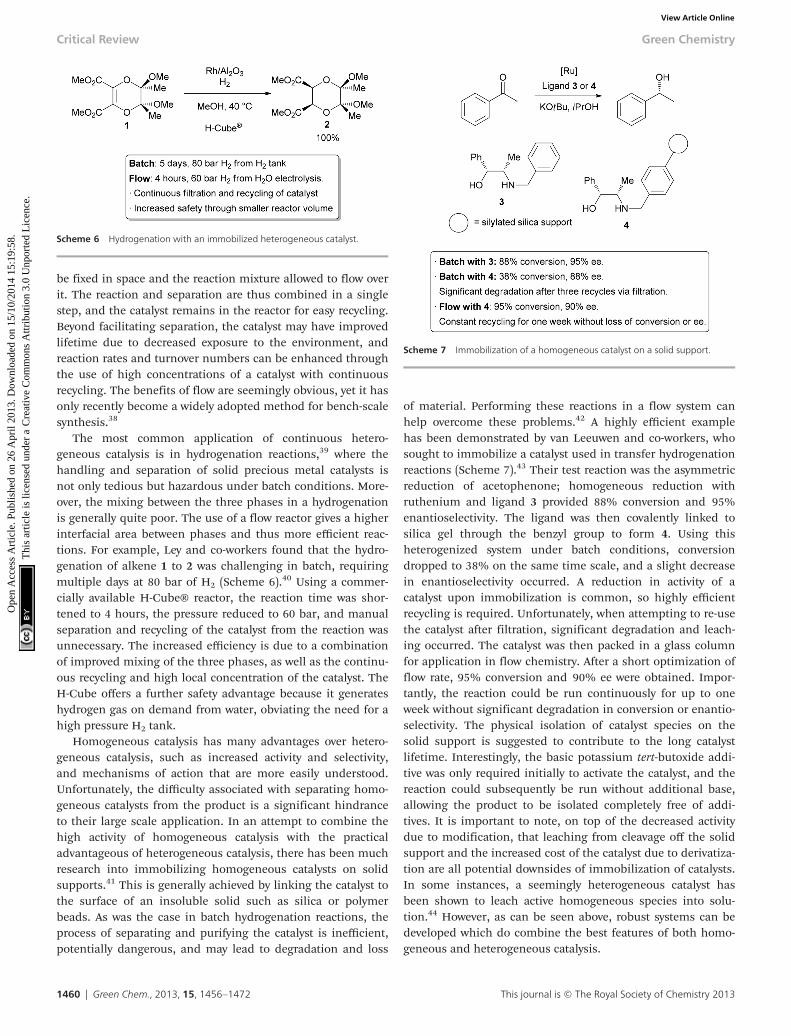
be fixed in space and the reaction mixture allowed to flow overit. The reaction and separation are thus combined in a singlestep, and the catalyst remains in the reactor for easy recycling.Beyond facilitating separation, the catalyst may have improvedlifetime due to decreased exposure to the environment, andreaction rates and turnover numbers can be enhanced throughthe use of high concentrations of a catalyst with continuousrecycling. The benefits of flow are seemingly obvious, yet it hasonly recently become a widely adopted method for bench-scalesynthesis.38
The most common application of continuous hetero-geneous catalysis is in hydrogenation reactions,39 where thehandling and separation of solid precious metal catalysts isnot only tedious but hazardous under batch conditions. More-over, the mixing between the three phases in a hydrogenationis generally quite poor. The use of a flow reactor gives a higherinterfacial area between phases and thus more efficient reac-tions. For example, Ley and co-workers found that the hydro-genation of alkene 1 to 2 was challenging in batch, requiringmultiple days at 80 bar of H2 (Scheme 6).40 Using a commer-cially available H-Cube® reactor, the reaction time was shor-tened to 4 hours, the pressure reduced to 60 bar, and manualseparation and recycling of the catalyst from the reaction wasunnecessary. The increased efficiency is due to a combinationof improved mixing of the three phases, as well as the continu-ous recycling and high local concentration of the catalyst. TheH-Cube offers a further safety advantage because it generateshydrogen gas on demand from water, obviating the need for ahigh pressure H2 tank.
Homogeneous catalysis has many advantages over hetero-geneous catalysis, such as increased activity and selectivity,and mechanisms of action that are more easily understood.Unfortunately, the difficulty associated with separating homo-geneous catalysts from the product is a significant hindranceto their large scale application. In an attempt to combine thehigh activity of homogeneous catalysis with the practicaladvantageous of heterogeneous catalysis, there has been muchresearch into immobilizing homogeneous catalysts on solidsupports.41 This is generally achieved by linking the catalyst tothe surface of an insoluble solid such as silica or polymerbeads. As was the case in batch hydrogenation reactions, theprocess of separating and purifying the catalyst is inefficient,potentially dangerous, and may lead to degradation and loss
of material. Performing these reactions in a flow system canhelp overcome these problems.42 A highly efficient examplehas been demonstrated by van Leeuwen and co-workers, whosought to immobilize a catalyst used in transfer hydrogenationreactions (Scheme 7).43 Their test reaction was the asymmetricreduction of acetophenone; homogeneous reduction withruthenium and ligand 3 provided 88% conversion and 95%enantioselectivity. The ligand was then covalently linked tosilica gel through the benzyl group to form 4. Using thisheterogenized system under batch conditions, conversiondropped to 38% on the same time scale, and a slight decreasein enantioselectivity occurred. A reduction in activity of acatalyst upon immobilization is common, so highly efficientrecycling is required. Unfortunately, when attempting to re-usethe catalyst after filtration, significant degradation and leach-ing occurred. The catalyst was then packed in a glass columnfor application in flow chemistry. After a short optimization offlow rate, 95% conversion and 90% ee were obtained. Impor-tantly, the reaction could be run continuously for up to oneweek without significant degradation in conversion or enantio-selectivity. The physical isolation of catalyst species on thesolid support is suggested to contribute to the long catalystlifetime. Interestingly, the basic potassium tert-butoxide addi-tive was only required initially to activate the catalyst, and thereaction could subsequently be run without additional base,allowing the product to be isolated completely free of addi-tives. It is important to note, on top of the decreased activitydue to modification, that leaching from cleavage off the solidsupport and the increased cost of the catalyst due to derivatiza-tion are all potential downsides of immobilization of catalysts.In some instances, a seemingly heterogeneous catalyst hasbeen shown to leach active homogeneous species into solu-tion.44 However, as can be seen above, robust systems can bedeveloped which do combine the best features of both homo-geneous and heterogeneous catalysis.
Scheme 6 Hydrogenation with an immobilized heterogeneous catalyst.
Scheme 7 Immobilization of a homogeneous catalyst on a solid support.
Critical Review Green Chemistry
1460 | Green Chem., 2013, 15, 1456–1472 This journal is © The Royal Society of Chemistry 2013
Ope
n A
cces
s A
rtic
le. P
ublis
hed
on 2
6 A
pril
2013
. Dow
nloa
ded
on 1
5/10
/201
4 15
:19:
58.
Thi
s ar
ticle
is li
cens
ed u
nder
a C
reat
ive
Com
mon
s A
ttrib
utio
n 3.
0 U
npor
ted
Lic
ence
.View Article Online

Another important method for recycling expensive catalystsis through the use of liquid–liquid biphasic conditions wherethe catalyst and reactants can be separated by extraction uponcompletion of the reaction. Such processes have already beenutilized on the medium and large scale in a continuous orsemi-continuous fashion.45,46 Recycling on a small scale istypically done through batch liquid–liquid extractions, butexamples using continuous methods are increasing.47–51 Arecent automated small scale recycling of a biphasic catalystsystem was demonstrated by the George group in the continu-ous oxidation of citronellol (Scheme 8).52 A highly fluorinatedporphyrin was used as the photocatalyst, and a combination ofhydrofluoroether (HFE) and scCO2 was used as the solvent.Under high pressure flow conditions, a single phase wasobserved. Depressurization occurred after the reactor, resultingin two phases – the organic product in one, and the catalystand HFE in the other. The denser, catalyst-containing fluorousphase was continuously pumped back through the reactor.With this method, the catalyst was recycled 10 times whilemaintaining 75% of its catalytic activity, giving an increase inTON of approximately 27-fold compared to previous batch con-ditions.53 Some leaching of the fluorinated catalyst into theorganic product was observed, accounting for the decreasedactivity over time.
Telescoping multistep reactions
The synthesis of fine chemicals sometimes requires multiplereactions and tedious work-up between each step is oftennecessary. Purification may involve the addition of a quench-ing reagent, multiple aqueous and organic extractions, theaddition of a drying agent, filtration, evaporation, and furtherpurification by chromatography, distillation, or recrystalliza-tion. These operations all require significant input of energyand materials that ultimately end up as large amounts ofwaste. Methods and technologies that eliminate or simplifyone or many of these steps can make a significant influenceon the environmental impact of a multistep chemical syn-thesis. Continuous processing is particularly suitable for ‘tele-scoping’ reaction sequences, and many methods have beendeveloped to facilitate this.54
One strategy utilizes solid supported reagents packed intocolumns which allow starting materials to flow in and productto be collected at the outlet without requiring separation of
the spent reagent. Different columns may be linked in series,allowing multistep processes to take place. Extra operationsmay also be necessary, such as solvent changes or the removalof unwanted side products. Methods for automating these pro-cesses have also been developed. An example from the Leygroup illustrates many of these technologies in the design of asingle apparatus to continuously prepare Imatinib (Gleevec)from simple starting materials (Scheme 9).55 Acid chloride 5and aniline 6 in DCM were flowed through a cartridge contain-ing immobilized DMAP as a nucleophilic catalyst, followed bya basic cartridge to scavenge any remaining 5. The formationof the amide 7 was monitored by an in-line UV spectrometerand subsequently added to a vial containing piperazine 8 inDMF at 50 °C, which facilitated evaporation of the DCM. Oncea particular amount of 7 was obtained, as indicated by the UVspectrometer, a connected autosampler would collect thissolution and pump it through an immobilized base to inducea substitution reaction, followed by an immobilized isonitrileto scavenge any remaining 8. An immobilized acid was used to‘catch’ amine 9 through protonation, allowing unreacted 7 togo to waste. ‘Release’ of 9 through deprotonation followed bythe addition of aniline 10 and a palladium catalyst facilitated across-coupling reaction, furnishing the crude Imatinib, whichwas then evaporated onto a silica gel column for automatedchromatography. Pure product was isolated in 32% overallyield and >95% purity. While not explicitly demonstrated, thepossibility of using this apparatus to form analogs by usingmodified starting materials is proposed. The ability to performmulti-step synthesis of pharmaceuticals without handling ofthe intermediates is particularly interesting, as exposure tothese species can be hazardous.
The above example utilizes packed cartridges of scavengersto effect purification. An alternative method is to more closelyemulate typical batch purification operations such as distilla-tion and extraction, but on a small, continuous scale. Severaldifferent ‘chip’ purification devices have been developed forthis purpose.56–65 Some of these technologies were usedtogether in a combined triflation/Heck reaction of phenols(Scheme 10).66 After the initial triflation step in dichloro-methane, the product is combined with a stream of aqueousHCl and passed on to a chip containing a membrane thatallows the organic phase to pass through while the aqueousstream is passed to waste. The purified triflate then combineswith a stream of DMF and the material enters a distillationdevice heated to 70 °C which allows the volatile dichloro-methane to be carried out of the reactor with a stream of nitro-gen gas. The product then enters a final reactor where itcombines with a stream of alkene and catalyst to form theHeck product. The whole reactor was operated continuouslyfor 5.5 hours, generating approximately 32 mg of product perhour.
Integration of multiple reaction steps, separations, andpurifications into one continuous process has great potentialfor avoiding energy intensive and wasteful intermediate purifi-cation. While great progress has been made, the developmentof a truly general set of reagents, methods, and devices still
Scheme 8 Automated recycling of a biphasic catalyst system.
Green Chemistry Critical Review
This journal is © The Royal Society of Chemistry 2013 Green Chem., 2013, 15, 1456–1472 | 1461
Ope
n A
cces
s A
rtic
le. P
ublis
hed
on 2
6 A
pril
2013
. Dow
nloa
ded
on 1
5/10
/201
4 15
:19:
58.
Thi
s ar
ticle
is li
cens
ed u
nder
a C
reat
ive
Com
mon
s A
ttrib
utio
n 3.
0 U
npor
ted
Lic
ence
.View Article Online

requires more research. Immobilized reagents can be wastefulto scale up, and there are significant limitations to currentmicroreactor extraction and distillation technologies. Crystalli-zation is another very important technique in pharmaceutical
synthesis, and while there are an increasing number ofmethods for continuous crystallization,67,68 it is yet to be usedas an intermediate purification step in an automated multi-step synthesis. Lastly, large scale applications of such complex,streamlined processes are required before a thorough assess-ment of their environmental impact in comparison with tra-ditional batch routes can be made.
Readily accessible and scalable photochemistry
Light has long been recognized as a valuable tool for perform-ing organic reactions. It acts as a traceless reagent, addingenergy to a chemical system without generating waste in theprocess. Historically, UV light has found most application insynthesis; however recent studies have shown that visible lightcan affect a wide range of useful transformations as well.69,70
While photochemistry has been used on the industrial scale, itis still uncommon in the pharmaceutical industry. This islikely due to the challenges associated with performing photo-chemistry on a preparative scale, where the volume of thereactor is too large to allow light to penetrate through. Flowchemistry provides a more efficient method to access photo-chemical transformations in a range of scales with inexpensivelaboratory equipment.71–73 In general, the reaction is pumped
Scheme 9 Multistep synthesis of Imatinib (Gleevec).49
Scheme 10 Triflation/Heck coupling facilitated by automated extraction anddistillation.64
Critical Review Green Chemistry
1462 | Green Chem., 2013, 15, 1456–1472 This journal is © The Royal Society of Chemistry 2013
Ope
n A
cces
s A
rtic
le. P
ublis
hed
on 2
6 A
pril
2013
. Dow
nloa
ded
on 1
5/10
/201
4 15
:19:
58.
Thi
s ar
ticle
is li
cens
ed u
nder
a C
reat
ive
Com
mon
s A
ttrib
utio
n 3.
0 U
npor
ted
Lic
ence
.View Article Online

through transparent polymer tubing or a transparent chipmicroreactor which is irradiated with a light source. The smalldiameter of the channels allows good light penetration, and allmolecules are exposed to similar amounts of heat and light.Since no component of the reaction is shielded from the lightsource, photochemical reactions performed in flow are oftenfound to be orders of magnitude faster than the correspondingbatch reactions. In a recent example, Stephenson and co-workers investigated intramolecular radical reactions withalkyl halides which traditionally require toxic reagents such atrialkyltin hydrides (Scheme 11).74 In batch using a rutheniumcatalyst, a stoichiometric base, and a 15 W fluorescent lamp, arange of tin-free radical cyclization reactions could be com-pleted on ∼0.1 mmol scale with a 12 hour reaction time.Scaling of the batch process was inefficient, and attempts atprocessing grams of material failed after 2 days reactiontime.75 To overcome this issue, a simple flow reactor wasdesigned with an assembly of blue LEDs (5.88 W) irradiating acoil of PFA tubing which carries the reaction mixture. Thesmall diameter of the tubing allows for optimal absorbance ofthe light, and reaction times of just 1 minute were obtained,corresponding to an output of 2.88 mmol h−1. In comparison,the unoptimized batch reactor produced approximately0.012 mmol h−1.72 The ability to obtain high outputs fromsmall reactors makes application of green photochemistrymuch more efficient and scalable.
More data using less material and time
Reactions for the purpose of discovery, optimization, andkinetic analysis seek only to gain information about a given setof conditions, not to form large amounts of products. To mini-mize waste generation, it is desirable to perform these trans-formations on as small a scale as is practical. The μL volumesizes and the ability to easily manipulate reaction conditionssuch as temperature, pressure, and time make microreactortechnology very effective in gathering large amounts of datawith small amounts of material. Moreover, investigating thereaction on a small scale allows one to evaluate the intrinsicbehaviour without worrying about issues with mixing and heattransfer. These advantages of small scale reaction analysis arefurther enhanced by technologies available for active monitor-ing of products. The output of the microreactor has been
integrated with a range of analytical techniques,76 includingUV,77 IR,78 Raman,79 fluorescence,80 NMR,81 HPLC,82 andMS83 devices.
The continuous nature of flow chemistry and the ability toactively monitor the results of a reaction also provide a uniqueopportunity for automation.84 Several groups have developedmethods for ‘self-optimizing’ chemical reactions,85–87 as wellas techniques for obtaining useful kinetic data.88,89 In ageneral approach, a reactor is connected to an instrumentcapable of in-line monitoring of a desired property (e.g. yield).This feeds information to a computer, which is in turn con-nected to the syringe pumps and/or temperature controller ofthe reactor. Stoichiometry, temperature, and time are thuslinked via a computer. An algorithm is used to suggest newconditions, a yield is obtained after completion of the reaction,and the process repeats itself until a maximum yield is identi-fied. A recent example was carried out by Moore and Jensen,who explored a number of different algorithms for theoptimization of a Paal Knorr reaction (Scheme 12).90 A 232 μLchip reactor was used along with a commercially available IRflow cell which was calibrated to determine the concentration,and thus yield, of the desired product at the outlet of thereactor. Temperatures ranging from 30 °C to 130 °C andreaction times from 2 to 30 minutes were evaluated.Stoichiometry was not investigated in this particular exampleto avoid trivializing the optimization through using onereagent in large excess. With the most effective algorithm,only 38 experiments were required to find the optimal con-ditions. The highest conversions were identified at the extremeof the parameter ranges; however, optimal production con-ditions were at 130 °C and 12.35 minutes, giving a conversionof 81%. Running a large number of reactions in batch is alsopossible with, for example, a 96-well plate. However, thesequential nature of the automated flow system with inline IRallows the maximum amount of data to be gathered withlimited material, as the result of one reaction can be used toguide the next experiment. On the other hand, efficientmethods for analyzing discrete variables such as solvent andcatalyst have not yet been integrated into automated flowoptimizations, leaving significant opportunities for furtherdevelopment.
Scheme 11 Photochemical alkylation.
Scheme 12 Automated optimization of temperature and time.
Green Chemistry Critical Review
This journal is © The Royal Society of Chemistry 2013 Green Chem., 2013, 15, 1456–1472 | 1463
Ope
n A
cces
s A
rtic
le. P
ublis
hed
on 2
6 A
pril
2013
. Dow
nloa
ded
on 1
5/10
/201
4 15
:19:
58.
Thi
s ar
ticle
is li
cens
ed u
nder
a C
reat
ive
Com
mon
s A
ttrib
utio
n 3.
0 U
npor
ted
Lic
ence
.View Article Online
Safe, practical use of gases in gas–liquid phase reactions
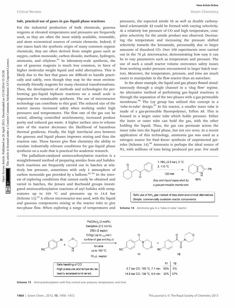
For the industrial production of bulk chemicals, gaseousreagents at elevated temperatures and pressures are frequentlyused, as they are often the most widely available, renewable,and atom economical sources of certain elements. Indeed, ifone traces back the synthetic origin of many common organicchemicals, they are often derived from simple gases such asoxygen, carbon monoxide, carbon dioxide, methane, hydrogen,ammonia, and ethylene.91 In laboratory-scale synthesis, theuse of gaseous reagents is much less common, in favor ofhigher molecular weight liquid and solid alternatives. This islikely due to the fact that gases are difficult to handle practi-cally and safely, even though they may be the most environ-mentally friendly reagents for many chemical transformations.Thus, the development of methods and technologies for per-forming gas–liquid biphasic reactions on a small scale isimportant for sustainable synthesis. The use of microreactortechnology can contribute to this goal. The reduced size of thereactor means increased safety when working under highpressures and temperatures. The flow rate of the gas can bevaried, allowing controlled stoichiometry, increased productpurity and reduced gas waste. A higher surface area to volumeratio of the reactor decreases the likelihood of hazardousthermal gradients. Finally, the high interfacial area betweenthe gaseous and liquid phases improves mixing and thus thereaction rate. These factors give flow chemistry the ability toemulate industrially relevant conditions for gas–liquid phasesynthesis on a scale that is practical for academic research.
The palladium-catalyzed aminocarbonylation reaction is astraightforward method of preparing amides from aryl halides.Such reactions are frequently carried out in batches at rela-tively low pressure, sometimes with only 1 atmosphere ofcarbon monoxide gas provided by a balloon.92–94 In the inter-est of exploring conditions that cannot easily be obtained andvaried in batches, the Jensen and Buchwald groups investi-gated aminocarbonylation reactions of aryl halides with temp-eratures up to 160 °C and pressures up to 14.8 bar(Scheme 13).95 A silicon microreactor was used, with the liquidand gaseous components mixing at the reactor inlet to givetwo-phase flow. When exploring a range of temperatures and
pressures, the expected amide 11 as well as double carbony-lated α-ketoamide 12 could be formed with varying selectivity.At a relatively low pressure of CO and high temperature, com-plete selectivity for the amide product was observed. Decreas-ing the temperature and increasing the pressure shiftedselectivity towards the ketoamide, presumably due to largeramounts of dissolved CO. Over 100 experiments were carriedout in the 78 μL microreactor, demonstrating how easy it canbe to vary parameters such as temperature and pressure. Theuse of such a small reactor volume overcomes safety issuesfrom working under pressure encountered in larger batch reac-tors. Moreover, the temperature, pressure, and time are mucheasier to manipulate in the flow reactor than an autoclave.
In the above example, the liquid and gas phases flowed simul-taneously through a single channel in a ‘slug flow’ regime.An alternative method of performing gas–liquid reactions isthrough the separation of the two phases with a gas-permeablemembrane.96 The Ley group has utilized this concept in a‘tube-in-tube’ design.97 In his reactor, a smaller inner tube ismade of a gas-permeable fluoropolymer, Teflon AF. This ishoused in a larger outer tube which holds pressure. Eitherthe inner or outer tube can hold the gas, with the otherholding the liquid. Thus, the gas can permeate across theinner tube into the liquid phase, but not vice versa. In a recentapplication of this technology, ammonia gas was used as anitrogen source for Paal–Knorr synthesis of unprotected pyr-roles (Scheme 14).98 Ammonia is perhaps the ideal source ofN1, with millions of tons being produced per year. For small
Scheme 13 Aminocarbonylation with fine control over pressure, temperature, and time.
Scheme 14 Ammonia gas in a ‘tube-in-tube’ reactor.
Critical Review Green Chemistry
1464 | Green Chem., 2013, 15, 1456–1472 This journal is © The Royal Society of Chemistry 2013
Ope
n A
cces
s A
rtic
le. P
ublis
hed
on 2
6 A
pril
2013
. Dow
nloa
ded
on 1
5/10
/201
4 15
:19:
58.
Thi
s ar
ticle
is li
cens
ed u
nder
a C
reat
ive
Com
mon
s A
ttrib
utio
n 3.
0 U
npor
ted
Lic
ence
.View Article Online

scale synthetic applications, however, less atom economicalammonium salts or pre-made commercially available stocksolutions are generally used for practical reasons. Thesereagents are problematic when elevated temperatures arerequired, as the volatile ammonia will evaporate out of thereaction vessel. To perform the pyrrole synthesis, the reactorwas divided into two sections. The first section contained thetube-in-tube setup with starting material in methanol on theoutside and 3.5 bar ammonia on the inside, all cooled to 0 °C.This allowed fast diffusion of the ammonia into the organicphase. The solution then entered a heated section of thereactor where the reaction took place under high pressure toprevent outgassing of ammonia. Excellent yields could beobtained in 120 minutes from the time when reagents aremixed to the outlet. Importantly, all components of the reactorset-up are commercially available and are relatively straightfor-ward to set up, making it ideal for small scale applications.The high cost and thermal sensitivity of Teflon AF tubing is alimitation on larger scale.
Safe use of potentially hazardous reagents
The small size of microreactors means that only μL volumes ofreactants and reagents are exposed to one another at a giventime. This has significant safety implications, as the hazardsof reactor failure are low, even in the worst case scenario. Assuch, there has been much interest in the advantages of per-forming useful but hazardous chemical reactions in small flowreactors. For example, reactions with both fluorine gas99 andliquid or solid fluorinating reagents,100,101 high energy organo-metallics,102,103 azides,104,105 and diazo compounds106,107 haveall been studied in flow. A particularly useful way of increasingsafety when using hazardous reagents is through theirimmediate synthesis, use, and quench, all within a microreac-tor. This avoids the need to transport and stockpile large quan-tities of such chemicals, instead allowing for the production ofexactly the required amount of material on-site, on-demand.
Diazomethane is a powerful reagent, capable of inducinguseful transformations such as methylation and cyclopropana-tion reactions with nitrogen gas being the only side product.Unfortunately, it is also highly explosive, volatile, and toxic,and is often avoided in favour of less efficient reagents.Methods for the continuous production and utilization of di-azomethane can significantly decrease the safety hazardsassociated with its use.108 The Stark group has developed auseful, small scale method for the rapid generation and use ofdiazomethane from Diazald (Scheme 15).109 For their testsystem, benzoic acid was methylated to methyl benzoate in amicroreactor. A mixed solvent system of isopropanol anddiethylene glycol ethyl ether was required to avoid the for-mation of solid precipitate. An excess of acid was used toensure complete consumption of the diazomethane. Goodyields were obtained with very fast reaction times, suggestingthat moles of material could be produced in a day from asingle microreactor. Most importantly, the total amount of di-azomethane present at any given time was negligible.
Flow chemistry on large scaleContinuous operation
Scaling up of a chemical reaction often requires wasteful re-optimization of reaction conditions due to the change in mixingand heating properties. As such, reactions which work well onthe bench scale might need increased reaction times, cryo-genic conditions, or may be simply impossible to perform on aprocess scale. A good reaction should be easily translatedbetween different scales without requiring reoptimization.This is particularly important for green chemistry, since agreen process needs to be scalable to have the greatest impact.In a continuous reaction, the most straightforward way tochange the total amount of product prepared is by changingthe length of time that the reactor is run. For example, increas-ing the operating time from 10 minutes to 1 week gives a 1000-fold increase in output. In contrast, changing the total outputof a batch reaction requires either running the reaction mul-tiple times in a small reactor or increasing the reactor size,which may require changing the conditions. Thus, a continu-ous reaction allows one to readily choose the amount ofmaterial produced without modifying the process or runningmultiple batches, meeting the green engineering principle tomeet needs and minimize excess. This is particularly impor-tant in larger scale chemistry, where the cost and complexity ofreaction vessels make changing the total output morechallenging.
Scaling out
To further increase the scale of a flow reactor while still takingadvantage of the good mixing and heat transfer properties ofmicroreactors, multiple reactors can be run simultaneously,referred to as numbering up, parallelization, or scaling out.Pumping and heating dozens of chip or tubular microreactorsis difficult, so a more practical method may be to design areactor with multiple channels which only requires a singlepump and heating apparatus. The Styring group implementedthis idea in a scaled up Kumada coupling (Scheme 16). In theinitial single reactor screening, an immobilized nickel specieswas identified which could catalyze the reaction at room temp-erature, producing 35.4 mg product per hour.110 A simple,stainless steel column packed with the catalyst was used. Toscale the process up, a vessel was designed featuring 120
Scheme 15 Preparation and immediate use of diazomethane.
Green Chemistry Critical Review
This journal is © The Royal Society of Chemistry 2013 Green Chem., 2013, 15, 1456–1472 | 1465
Ope
n A
cces
s A
rtic
le. P
ublis
hed
on 2
6 A
pril
2013
. Dow
nloa
ded
on 1
5/10
/201
4 15
:19:
58.
Thi
s ar
ticle
is li
cens
ed u
nder
a C
reat
ive
Com
mon
s A
ttrib
utio
n 3.
0 U
npor
ted
Lic
ence
.View Article Online

capillaries of identical shape and volume to the single channelreactor.111 The entire apparatus was small enough to fit on topof a hotplate-stirrer. A positive pressure of nitrogen was usedto pump the reactants through the bed of nickel catalyst, andsimilar reaction times and yields were obtained as was foundin the single channel reactor. The reaction was run continu-ously for 31 hours without a noticeable change in yield and nodetectable leaching of the catalyst, giving approximately5 grams of product per hour.
Scaling up through increasing channel length and diameter
A microreactor has, by definition, volumes in the microliterrange. While numbering up is a possibility, there are limit-ations to how many flow reactors can be utilized simul-taneously. The cost of individual reactors, as well as thechallenge in pumping liquid evenly throughout the reactors,can quickly become impractical. To scale up to the mL (meso-reactor) range, however, risks losing some of the main advan-tages of performing reactions in microreactors. Mixing bydiffusion may no longer be sufficient, highly exothermic reac-tions may be challenging to control, and flow may become tur-bulent. These factors may prevent all molecules fromexperiencing the same conditions throughout the reaction.Careful engineering may be used to understand and overcomethese problems. For example, heat sinks and static or dynamicmicromixers can be incorporated into the system, and anunderstanding of the reaction kinetics and flow patternswithin the reactor can also be used to modify and optimizereaction conditions. To demonstrate scale-up in reactorvolume of an industrially relevant reaction, the Jensen andJamison groups studied the opening of styrene oxide by aprimary amine to give a β-amino alcohol analogous to thatfound in pharmaceuticals such as Salbutamol and Indacaterol(Scheme 17).112 Side products resulting from poor regioselec-tivity or bisalkylation must be avoided, which make the reac-tion complex. The system must be well understood to ensurethat selectivity is not altered due to changes in mass and heattransfer on scale-up. In a 125 μL microreactor, over 100 exper-iments were performed in an 8 hour period to obtain kineticdata for the formation of both the mono- and bis-alkylationproducts. The results showed that the best yield and selectivitywere obtained at high temperature and high amine to epoxide
ratio. Knowledge of the kinetics and key parameters of thereactor allowed 100 fold scale-up into a 12.5 mL tubular stain-less steel mesoreactor. In a single test run, 9.2 grams ofproduct (78% yield) were obtained over 30 minutes at a 110second residence time, demonstrating that scale-up in flowcan be safe, predictable, and can avoid wasteful reoptimiza-tion. It is worth noting that the reaction was performedefficiently using ethanol as the solvent far above its boilingpoint, providing another example of how the availability of agreater range of reaction conditions can allow for higher reac-tivity and the use of green solvents.
We have already discussed how reactions that require drop-wise addition of reagents at cryogenic temperatures in batchmay be run at higher temperatures in microreactors due to thehigh surface area to volume ratio and good heat transfer.Researchers at Lonza and Corning designed a reactor for thepurpose of retaining the benefits of μL volume reactors whileallowing high production.113 Their solution was to implementmultiple injection ports, emulating the common batch tech-nique of dosing or dropwise addition of one reagent. To testtheir design, an exceptionally exothermic Grignard addition toan acyl chloride was chosen, with an enthalpy of 260 kJmol−1.114 When running at a total flow rate of 80 g min−1, arespectable yield of 50% could be obtained for this challengingtransformation (Scheme 18). The reactor was operated withoutinterruption for several weeks. The local generation of
Scheme 16 120-fold scale-out by increasing the number of reactor channels.
Scheme 17 Scale-up by increasing the reactor size.
Scheme 18 A highly exothermic Grignard reaction.
Critical Review Green Chemistry
1466 | Green Chem., 2013, 15, 1456–1472 This journal is © The Royal Society of Chemistry 2013
Ope
n A
cces
s A
rtic
le. P
ublis
hed
on 2
6 A
pril
2013
. Dow
nloa
ded
on 1
5/10
/201
4 15
:19:
58.
Thi
s ar
ticle
is li
cens
ed u
nder
a C
reat
ive
Com
mon
s A
ttrib
utio
n 3.
0 U
npor
ted
Lic
ence
.View Article Online

hotspots was attributed as the primary reason for side-productformation, and further temperature reductions were challen-ging due to the poor solubility of the Grignard reagent.
Scaling of potentially hazardous gas–liquid transformations
As discussed earlier, performing reactions with hazardousgases in a continuous process offer advantages in improvedrates due to increased mixing of the gas and liquid phases, aswell as higher safety due to the small volumes of pressurizedequipment needed. These benefits may lessen upon scalingfrom a microreactor to a mesoreactor, but with proper precau-tions, performing gas–liquid reactions in flow can still offergreat improvements over batch processes. For example, oxi-dation reactions using O2 as the stoichiometric oxidant arehighly desirable due to the high availability and low environ-mental impact of molecular oxygen. For these reasons, its usein academic research, particularly with transition metal cata-lysts, has been increasing.115–120 Oxygen is also frequentlyused in the bulk chemical industry, such as for the productionof ethylene glycol from ethylene.121 Application to fine chemi-cals and pharmaceuticals, however, is much less common, inpart due to safety concerns when mixing large volumes of O2
with flammable solvents. Demonstration of the safe and selec-tive use of O2 on the mesoscale is a challenging but importantgoal. The Stahl group, in collaboration with researchers at EliLilly, sought to scale up a palladium-catalyzed aerobic oxi-dation of alcohols to ketones, a transformation frequentlycarried out using wasteful stoichiometric reagents(Scheme 19).122 Under batch conditions, the oxidation of1-phenylethanol proceeds with a 90% yield using 1 bar of pureoxygen over 18 h on a 1 mmol scale at room temperature.Upon converting to a 5 mL flow reactor, pressure and tempera-ture were increased, and a comparable yield could be obtainedwith just a 45 minute residence time. Interestingly, catalystdecomposition was problematic when using elevated tempera-tures in batch, suggesting that the improved gas–liquid mixingin flow is critical. The oxidation was then scaled to a 400 mLreactor at 100 °C with dilution of the O2 in N2, and further
scaled to a 7 L reactor with a decrease in the loading of palla-dium. Dilution of the gas served as a safety feature, but alsoallowed increased flow rates to be used, enhancing mixing.The use of a long coil of stainless steel tubing with a relativelysmall inner diameter gave a further increase in linear velo-cities, and thus mixing, of the reactants. Nonetheless, anincrease in residence time was required on each jump in scale.In the 7 L reactor, an output of approximately 52 g h−1 couldbe obtained. A 99.5% yield was obtained when processing 1 kgof material, demonstrating that O2 can be used safely andselectively on the mesoscale.
Multi-kilo scale-up under GMP conditions
Examples of flow processes being used to produce exception-ally large amounts of material are becoming increasinglycommon as industrial researchers become more knowledge-able about the benefits of continuous reactions. The aboveexamples from academic groups serve to illustrate that reac-tions optimized in small reactors processing tens to hundredsof mg hour−1 of material can be scaled up to several grams perhour. Projects in process chemistry are often time-sensitive,however, and production of multiple kg of material may beneeded in a short amount of time. An example of how theefficient scaling of a flow reaction can save time and reducewaste is provided by a group of researchers at Eli Lilly in theirkg synthesis of a key drug intermediate under GMP conditions(Scheme 20). In batch, ketoamide 13 was condensed withNH4OAc and cyclized to form imidazole 14 at 100 °C inbutanol on a 1 gram scale. However, side product formationbecame a significant problem on multiple runs at a 250 g
Scheme 19 Safe scale-up of an aerobic oxidation. Scheme 20 Kilogram-scale synthesis of an imidazole API precursor.
Green Chemistry Critical Review
This journal is © The Royal Society of Chemistry 2013 Green Chem., 2013, 15, 1456–1472 | 1467
Ope
n A
cces
s A
rtic
le. P
ublis
hed
on 2
6 A
pril
2013
. Dow
nloa
ded
on 1
5/10
/201
4 15
:19:
58.
Thi
s ar
ticle
is li
cens
ed u
nder
a C
reat
ive
Com
mon
s A
ttrib
utio
n 3.
0 U
npor
ted
Lic
ence
.View Article Online
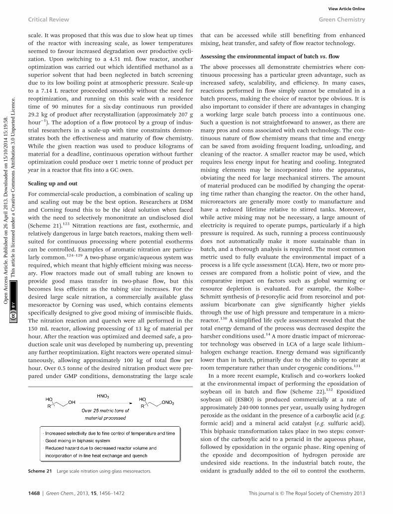
scale. It was proposed that this was due to slow heat up timesof the reactor with increasing scale, as lower temperaturesseemed to favour increased degradation over productive cycli-zation. Upon switching to a 4.51 mL flow reactor, anotheroptimization was carried out which identified methanol as asuperior solvent that had been neglected in batch screeningdue to its low boiling point at atmospheric pressure. Scale-upto a 7.14 L reactor proceeded smoothly without the need forreoptimization, and running on this scale with a residencetime of 90 minutes for a six-day continuous run provided29.2 kg of product after recrystallization (approximately 207 ghour−1). The adoption of a flow protocol by a group of indus-trial researchers in a scale-up with time constraints demon-strates both the effectiveness and maturity of flow chemistry.While the given reaction was used to produce kilograms ofmaterial for a deadline, continuous operation without furtheroptimization could produce over 1 metric tonne of product peryear in a reactor that fits into a GC oven.
Scaling up and out
For commercial-scale production, a combination of scaling upand scaling out may be the best option. Researchers at DSMand Corning found this to be the ideal solution when facedwith the need to selectively mononitrate an undisclosed diol(Scheme 21).123 Nitration reactions are fast, exothermic, andrelatively dangerous in large batch reactors, making them well-suited for continuous processing where potential exothermscan be controlled. Examples of aromatic nitration are particu-larly common.124–129 A two-phase organic/aqueous system wasrequired, which meant that highly efficient mixing was necess-ary. Flow reactors made out of small tubing are known toprovide good mass transfer in two-phase flow, but thisbecomes less efficient as the tubing size increases. For thedesired large scale nitration, a commercially available glassmesoreactor by Corning was used, which contains elementsspecifically designed to give good mixing of immiscible fluids.The nitration reaction and quench were all performed in the150 mL reactor, allowing processing of 13 kg of material perhour. After the reaction was optimized and deemed safe, a pro-duction scale unit was developed by numbering up, preventingany further reoptimization. Eight reactors were operated simul-taneously, allowing approximately 100 kg of total flow perhour. Over 0.5 tonne of the desired nitration product were pre-pared under GMP conditions, demonstrating the large scale
that can be accessed while still benefiting from enhancedmixing, heat transfer, and safety of flow reactor technology.
Assessing the environmental impact of batch vs. flow
The above processes all demonstrate chemistries where con-tinuous processing has a particular green advantage, such asincreased safety, scalability, and efficiency. In many cases,reactions performed in flow simply cannot be emulated in abatch process, making the choice of reactor type obvious. It isalso important to consider if there are advantages in changinga working large scale batch process into a continuous one.Such a question is not straightforward to answer, as there aremany pros and cons associated with each technology. The con-tinuous nature of flow chemistry means that time and energycan be saved from avoiding frequent loading, unloading, andcleaning of the reactor. A smaller reactor may be used, whichrequires less energy input for heating and cooling. Integratedmixing elements may be incorporated into the apparatus,obviating the need for large mechanical stirrers. The amountof material produced can be modified by changing the operat-ing time rather than changing the reactor. On the other hand,microreactors are generally more costly to manufacture andhave a reduced lifetime relative to stirred tanks. Moreover,while active mixing may not be necessary, a large amount ofelectricity is required to operate pumps, particularly if a highpressure is required. As such, running a process continuouslydoes not automatically make it more sustainable than inbatch, and a thorough analysis is required. The most commonmetric used to fully evaluate the environmental impact of aprocess is a life cycle assessment (LCA). Here, two or more pro-cesses are compared from a holistic point of view, and thecomparative impact on factors such as global warming orresource depletion is evaluated. For example, the Kolbe–Schmitt synthesis of β-resorcylic acid from resorcinol and pot-assium bicarbonate can give significantly higher yieldsthrough the use of high pressure and temperature in a micro-reactor.130 A simplified life cycle assessment revealed that thetotal energy demand of the process was decreased despite theharsher conditions used.14 A more drastic impact of microreac-tor technology was observed in LCA of a large scale lithium–
halogen exchange reaction. Energy demand was significantlylower than in batch, primarily due to the ability to operate atroom temperature rather than under cryogenic conditions.131
In a more recent example, Kralisch and co-workers lookedat the environmental impact of performing the epoxidation ofsoybean oil in batch and flow (Scheme 22).132 Epoxidizedsoybean oil (ESBO) is produced commercially at a rate ofapproximately 240 000 tonnes per year, usually using hydrogenperoxide as the oxidant in the presence of a carboxylic acid (e.g.formic acid) and a mineral acid catalyst (e.g. sulfuric acid).This biphasic transformation takes place in two steps: conver-sion of the carboxylic acid to a peracid in the aqueous phase,followed by epoxidation in the organic phase. Ring opening ofthe epoxide and decomposition of hydrogen peroxide areundesired side reactions. In the industrial batch route, theoxidant is gradually added to the oil to control the exotherm.Scheme 21 Large scale nitration using glass mesoreactors.
Critical Review Green Chemistry
1468 | Green Chem., 2013, 15, 1456–1472 This journal is © The Royal Society of Chemistry 2013
Ope
n A
cces
s A
rtic
le. P
ublis
hed
on 2
6 A
pril
2013
. Dow
nloa
ded
on 1
5/10
/201
4 15
:19:
58.
Thi
s ar
ticle
is li
cens
ed u
nder
a C
reat
ive
Com
mon
s A
ttrib
utio
n 3.
0 U
npor
ted
Lic
ence
.View Article Online

Performing such a process in flow may offer advantages inmass transfer between the two phases and improved tempera-ture control; however, the batch process has already beendemonstrated to be effective and scalable. To determine if per-forming the epoxidation in flow was of any environmentalbenefit, a systematic evaluation of the input and output ofmaterial and energy was carried out. The energy demand permole of product was found to be lowest when performed athigh temperatures in a flow reactor (T > 100 °C) due todecreased reaction times; however, this effect levelled off at T >180 °C due to increased energy demand. In a best-case scen-ario, the authors note that switching the existing process to ahigh temperature flow reaction can give approximately 11–12%reduction in global warming and human toxicity potential.Considering that the largest factors in environmental impactof the process are from the starting material supply whichcannot be reduced beyond stoichiometric quantities, this is asignificant improvement. Economic feasibility was also foundto be favorable due to decreased personnel costs when operat-ing on a large scale in the continuous process. As the calcu-lations performed on the flow system are thus far theoretical,the development of a pilot plant is required before one can besure that the expectations can be fulfilled.
Advantages in large scale production from small reactors
In general, the improved mass and heat transfer available inmicroreactors, as well as the ability to continuously feedreagents and safely use high pressures, temperatures, and con-centrations, allows increased rates of chemical production tobe possible in small reactors. This has general advantages insafety and energy efficiency, but also provides the opportunityto develop more portable, small scale manufacturing plants.For example, the conversion of syngas to liquid fuels—theFischer Tropsch process—must be operated at a very highcapacity to keep the cost per barrel low. As such, it is desirableto build plants near the source of syngas to avoid long distancetransportation. Researchers at Velocys have developed a multi-channel microreactor that can obtain high efficiency at a muchlower production capacity than is capable with the traditionalroutes, reducing capital investment and operating costs(Scheme 23).133,134 Furthermore, the production capacity perunit mass of the reactor is significantly higher. This opens upthe potential to transport the reactor to the site of biomass,rather than the converse. This is particularly advantageous forsources of biomass that may not be large enough to justify the
development of a fixed facility. Application of this technologyto the preparation of liquid fuels from natural gas reserves,particularly those offshore, has also been proposed.
Conclusions
Flow chemistry and continuous manufacturing have becomeincreasingly recognized as a viable and, in many cases,superior alternative to batch processing. Continuous methodsgenerally offer increased safety, energy efficiency, scalability,and reproducibility. In certain cases, such as heterogeneouscatalysis and photochemistry, performing reactions in flowoffers further advantages that cannot be emulated in a round-bottom flask or stirred tank. The application of continuousmethods on a process scale has recently seen a rapid increase,demonstrating that these advantages are real and impactful.Further developments in academic labs and large scale appli-cations from industry will expand the types of transformationsthat can be performed more sustainably in flow.
Acknowledgements
S. G. N. thanks NSERC for a postdoctoral fellowship.
References
1 C. Wiles and P. Watts, Green Chem., 2012, 14, 38–54.2 S. V. Ley, Chem. Rec., 2012, 12, 378–390.3 J.-i. Yoshida, H. Kim and A. Nagaki, ChemSusChem, 2011,
4, 331–340.4 C. Jiménez-González, P. Poechlauer, Q. B. Broxterman,
B.-S. Yang, D. am Ende, J. Baird, C. Bertsch, R. E.Hannah, P. Dell’Orco, H. Noorman, S. Yee, R. Reintjens,A. Wells, V. Massonneau and J. Manley, Org. Process Res.Dev., 2011, 15, 900–911.
5 P. T. Anastas and M. M. Kirchhoff, Acc. Chem. Res., 2002,35, 686–694.
6 P. T. Anastas and J. B. Zimmerman, Environ. Sci. Technol.,2003, 37, 94A–101A.
7 N. G. Anderson, Org. Process Res. Dev., 2012, 16, 852–869.8 C. Wiles and P. Watts, Chem. Commun., 2011, 47, 6512–
6535.
Scheme 23 Microreactor technology helps overcome scale limitations in con-verting biomass to liquid fuels.
Scheme 22 Life cycle analysis of batch and flow syntheses of ESBO.
Green Chemistry Critical Review
This journal is © The Royal Society of Chemistry 2013 Green Chem., 2013, 15, 1456–1472 | 1469
Ope
n A
cces
s A
rtic
le. P
ublis
hed
on 2
6 A
pril
2013
. Dow
nloa
ded
on 1
5/10
/201
4 15
:19:
58.
Thi
s ar
ticle
is li
cens
ed u
nder
a C
reat
ive
Com
mon
s A
ttrib
utio
n 3.
0 U
npor
ted
Lic
ence
.View Article Online

9 J.-i. Yoshida, Flash Chemistry. Fast Organic Synthesis inMicrosystems, Wiley-Blackwell, 2008.
10 C. Wiles and P. Watts, Micro Reaction Technology inOrganic Synthesis, CRC Press, 2011.
11 Microwaves in Organic Synthesis, ed. A. Loupy, Wiley-VCH,Weinheim, 2006.
12 T. Razzaq and C. O. Kappe, Chem.–Asian. J., 2010, 5, 1274–1289.
13 W.-C. Shieh, S. Dell and O. Repič, Org. Lett., 2001, 3, 4279–4281.
14 U. Tilstam, Org. Process Res. Dev., 2012, 16, 1974–1978.15 T. N. Glasnov, J. D. Holbrey, C. O. Kappe, K. R. Seddon
and T. Yan, Green Chem., 2012, 14, 3071–3076.16 S. Heubschmann, D. Kralisch, V. Hessel, U. Krtschil
and C. Kompter, Chem. Eng. Technol., 2009, 32, 1757–1765.
17 R. Dach, J. J. Song, F. Roschanger, W. Samstag andC. H. Senanayake, Org. Process Res. Dev., 2012, 16, 1697–1706.
18 R. L. Hartman, J. P. McMullen and K. F. Jensen, Angew.Chem., Int. Ed., 2011, 50, 7502–7519.
19 V. Hessel, C. Hofmann, H. Löwe, A. Meudt, S. Scherer,F. Schönfeld and B. Werner, Org. Process Res. Dev., 2004, 8,511–523.
20 A. Nagaki, Y. Tomida, H. Usutani, H. Kim,N. Takabayashi, T. Nokami, H. Okamoto and J.-i. Yoshida,Chem.–Asian J., 2007, 2, 1513–1523.
21 T. Gustafsson, H. Sörensen and F. Pontén, Org. ProcessRes. Dev., 2012, 16, 925–929.
22 T. Kawaguchi, H. Miyata, K. Ataka, K. Mae and J.-I.Yoshida, Angew. Chem., Int. Ed., 2005, 44, 2413–2416.
23 A. K. Sharma and D. Swern, Tetrahedron Lett., 1974, 15,1503–1506.
24 A. K. Sharma, T. Ku, A. D. Dawson and D. Swern, J. Org.Chem., 1975, 40, 2758–2764.
25 J.-i. Yoshida, Chem. Rec., 2010, 10, 332–341.26 H. Löwe, V. Hessel, P. Löbe and S. Hubbard, Org. Process
Res. Dev., 2006, 10, 1144–1152.27 V. Hessel, Chem. Eng. Technol., 2009, 32, 1655–1681.28 X. Y. Mak, P. Laurino and P. H. Seeberger, Beilstein J. Org.
Chem., 2009, 5, DOI: 10.3762/bjoc.5.19.29 F. Sahena, I. S. M. Zaidul, S. Jinap, A. A. Karim, K. A.
Abbas, N. A. N. Norulaini and A. K. M. Omar, J. Food Eng.,2009, 95, 240–253.
30 D. J. Dixon and K. P. Jhonston, in Encyclopedia of Sepa-ration Technology, ed. D. M. Ruthven, John Wiley, 1997,1544–1569.
31 P. Licence, J. Ke, M. Sokolova, S. K. Ross and M. Poliakoff,Green Chem., 2003, 5, 99–104.
32 X. Han and M. Poliakoff, Chem. Soc. Rev., 2012, 41, 1428–1436.
33 S. Marre, Y. Roig and C. Aymonier, J. Supercrit. Fluids,2012, 66, 251–264.
34 F. Benito-Lopez, R. M. Tiggelaar, K. Salbut, J. Huskens,R. J. M. Egberink, D. N. Reinhoudt, H. J. G. E. Gardeniersand W. Verboom, Lab Chip, 2007, 7, 1345–1351.
35 R. Holliday, B. Y. M. Jong and J. W. Kolis, J. Supercrit.Fluids, 1998, 12, 255–260.
36 P. A. Hamley, T. Ilkenhans, J. M. Webster, E. García-Verdugo, E. Vernardou, M. J. Clarke, R. Auerbach, W. B.Thomas, K. Whiston and M. Poliakoff, Green Chem., 2002,4, 235–238.
37 E. Pérez, J. Fraga-Dubreuil, E. García-Verdugo, P. A.Hamley, M. L. Thomas, C. Yan, W. B. Thomas, D. Housley,W. Partenheimer and M. Poliakoff, Green Chem., 2011, 13,2397–2407.
38 C. G. Frost and L. Mutton, Green Chem., 2010, 12, 1687–1703.
39 M. Irfan, T. N. Glasnov and C. O. Kappe, ChemSusChem,2011, 4, 300–316.
40 C. F. Carter, I. R. Baxendale, M. O’Brien, J. P. V. Pavey andS. V. Ley, Org. Biomol. Chem., 2009, 7, 4594–4597.
41 P. McMorn and G. J. Hutchings, Chem. Soc. Rev., 2004, 33,108–122.
42 S. Ceylan and A. Kirschning, in Recoverable and RecyclableCatalysts, ed. M. Benaglia, John Wiley & Sons Ltd, 2009,pp. 379–410.
43 A. J. Sandee, D. G. I. Petra, J. N. H. Reek, P. C. J. Kamerand P. W. N. M. Van Leeuwen, Chem.–Eur. J., 2001, 7,1202–1208.
44 M. Pagliaro, V. Pandarus, R. Ciriminna, F. Belénd andP. D. Cerà, ChemCatChem, 2012, 4, 432–445.
45 C. W. Kohlpaintner, R. W. Fischer and B. Cornils, Appl.Catal., A, 2001, 221, 219–225.
46 W. A. Herrmann, C. W. Kohlpaintner, H. Bahrmann andW. Konkol, J. Mol. Catal., 1992, 73, 191.
47 A. B. Theberge, G. Whyte, M. Frenzel, L. M. Fidalgo,R. C. R. Wootton and W. T. S. Huck, Chem.Commun.,2009, 6225–6227.
48 A. Yoshida, X. Hao and J. Nishikido, Green Chem., 2003, 5,554–557.
49 E. Perperi, Y. Huang, P. Angeli, G. Manos, C. R. Mathison,D. J. Cole-Hamilton, D. J. Adams and E. G. Hope, DaltonTrans., 2004, 2062–2064.
50 S. Liu, T. Fukuyama, M. Sato and I. Ryu, Org. Process Res.Dev., 2004, 8, 477–481.
51 T. Fukuyama, M. T. Rahman, M. Sato and I. Ryu, Synlett,2008, 151–163.
52 J. F. B. Hall, X. Han, M. Poliakoff, R. A. Bourne andM. W. George, Chem. Commun., 2012, 48, 3073–3075.
53 R. A. Bourne, X. Han, M. Poliakoff and M. W. George,Angew. Chem., Int. Ed., 2009, 48, 5322.
54 D. Webb and T. F. Jamison, Chem. Sci., 2010, 1, 675–680.
55 M. D. Hopkin, I. R. Baxendale and S. V. Ley, Chem.Commun., 2010, 46, 2450–2452.
56 J. G. Kralj, H. R. Sahoo and K. F. Jensen, Lab Chip, 2007,7, 256–263.
57 R. L. Hartman, H. R. Sahoo, B. C. Yen and K. F. Jensen,Lab Chip, 2009, 9, 1843–1849.
58 M. O’Brien, P. Koss, D. L. Browne and S. V. Ley, Org.Biomol. Chem., 2012, 10, 7031–7036.
Critical Review Green Chemistry
1470 | Green Chem., 2013, 15, 1456–1472 This journal is © The Royal Society of Chemistry 2013
Ope
n A
cces
s A
rtic
le. P
ublis
hed
on 2
6 A
pril
2013
. Dow
nloa
ded
on 1
5/10
/201
4 15
:19:
58.
Thi
s ar
ticle
is li
cens
ed u
nder
a C
reat
ive
Com
mon
s A
ttrib
utio
n 3.
0 U
npor
ted
Lic
ence
.View Article Online

59 K. K. R. Tetala, J. W. Swarts, B. Chen, A. E. M. Janssen andT. A. van Beek, Lab Chip, 2009, 9, 2085–2092.
60 D. M. Fries, T. Voitl and P. R. von Rohr, Chem. Eng.Technol., 2008, 31, 1182–1187.
61 S. Aljbour, H. Yamada and T. Tagawa, Top. Catal., 2010,53, 694–699.
62 A. Smirnova, K. Shimura, A. Hibara, M. A. Proskurnin andT. Kitamori, Anal. Sci., 2007, 23, 103–107.
63 R. C. R. Wootton and A. J. deMello, Chem. Commun., 2004,266–267.
64 A. Hibara, K. Toshin, T. Tsukahara, K. Mawatari andT. Kitamora, Chem. Lett., 2008, 1064–1065.
65 Y. Zhang, S. Kato and T. Anazawa, Lab Chip, 2010, 10,899–908.
66 R. L. Hartman, J. R. Naber, S. L. Buchwald andK. F. Jensen, Angew. Chem., Int. Ed., 2010, 49, 899–903.
67 S. Lawton, G. Steele, P. Shering, L. Zhao, I. Laird andX.-W. Ni, Org. Process Res. Dev., 2009, 13, 1357–1363.
68 H. Zhao, J.-X. Wang, Q.-A. Wang, J.-F. Chen and J. Yun,Ind. Eng. Chem. Res., 2007, 46, 8229–8235.
69 J. Xuan and W.-J. Xiao, Angew. Chem., Int. Ed., 2012, 51,6828–6838.
70 J. M. R. Narayanam and C. R. J. Stephenson, Chem. Soc.Rev., 2011, 40, 102–113.
71 J. P. Knowles, L. D. Elliott and K. I. Booker-Milburn, Beil-stein J. Org. Chem., 2012, 8, 2025–2052.
72 M. Oelgemöller and O. Shvydkiv, Molecules, 2011, 16,7522–7550.
73 M. Oelgemoeller, Chem. Eng. Technol., 2012, 35, 1144–1152.
74 J. W. Tucker, J. M. R. Narayanam, S. W. Krabbe andC. R. J. Stephenson, Org. Lett., 2010, 12, 368–371.
75 J. W. Tucker, Y. Zhang, T. F. Jamison and C. R. J.Stephenson, Angew. Chem., Int. Ed., 2012, 51, 4144–4147.
76 J. Yue, J. C. Schouten and T. A. Nijhuis, Ind. Eng. Chem.Res., 2012, 51, 14583–14609.
77 F. Benito-Lopez, W. Verboom, M. Kakuta,J. G. E. Gardeniers, R. J. M. Egberink, E. R. Oosterbroek,A. van den Berg and D. N. Reinhoudt, Chem. Commun.,2005, 2857–2859.
78 H. Lange, C. F. Carter, M. D. Hopkin, A. Burke,J. G. Goode, I. R. Baxendale and S. V. Ley, Chem. Sci.,2011, 2, 765–769.
79 S. Mozharov, A. Nordon, D. Littlejohn, C. Wiles, P. Watts,P. Dallin and J. M. Girkin, J. Am. Chem. Soc., 2011, 133,3601–3608.
80 H. Song and R. F. Ismagilov, J. Am. Chem. Soc., 2003, 125,14613–14619.
81 L. Ciobanu, D. A. Jayawickrama, X. Zhang, A. G. Webband J. V. Sweedler, Angew. Chem., Int. Ed., 2003, 42,4669–4672.
82 C. J. Welch, X. Gong, J. Cuff, S. Dolman, J. Nyrop, F. Linand H. Rogers, Org. Process Res. Dev., 2009, 13, 1022–1025.
83 D. L. Browne, S. Wright, B. J. Deadman, S. Dunnage,I. R. Baxendale, R. M. Turner and S. V. Ley, RapidCommun. Mass Spectrom., 2012, 26, 1999–2010.
84 J. P. McMullen and K. F. Jensen, Annu. Rev. Anal. Chem.,2010, 3, 19–42.
85 J. P. McMullen, M. T. Stone, S. L. Buchwald andK. F. Jensen, Angew. Chem., Int. Ed., 2010, 49, 7076–7080.
86 A. J. Parrott, R. A. Bourne, G. R. Akien, D. J. Irvine andM. Poliakoff, Angew. Chem., Int. Ed., 2011, 50, 3788–3792.
87 S. Krishnadasan, R. J. C. Brown, A. J. deMello andJ. C. deMello, Lab Chip, 2007, 7, 1434–1441.
88 B. J. Reizman and K. F. Jensen, Org. Process Res. Dev.,2012, 16, 1770–1782.
89 J. P. McMullen and K. F. Jensen, Org. Process Res. Dev.,2011, 15, 398–407.
90 J. J. S. Moore and K. F. Jensen, Org. Process Res. Dev., 2012,16, 1409–1415.
91 P. G. Jessop, Green Chem., 2011, 13, 1391–1398. Support-ing information.
92 J. R. Martinelli, D. M. M. Freckmann and S. L. Buchwald,Org. Lett., 2006, 8, 4843–4846.
93 T. Ishiyama, H. Kizaki, T. Hayashi, A. Suzuki andN. Miyaura, J. Org. Chem., 1998, 63, 4726–4731.
94 A. Shoenberg and R. F. Heck, J. Org. Chem., 1974, 39,3327–3331.
95 E. R. Murphy, J. R. Martinelli, N. Zaborenko,S. L. Buchwald and K. F. Jensen, Angew. Chem., Int. Ed.,2007, 46, 1734–1737.
96 T. Noël and V. Hessel, ChemSusChem, 2013, 6(3), 405–407.97 A. Polyzos, M. O’Brien, T. P. Petersen, I. R. Baxendale and
S. V. Ley, Angew. Chem., Int. Ed., 2011, 50, 1190–1193.98 P. B. Cranwell, M. O’Brien, D. L. Browne, P. Koos,
A. Polyzos, M. Peña-López and S. V. Ley, Org. Biomol.Chem., 2012, 10, 5774–5779.
99 C. P. McPake and G. Sandford, Org. Process Res. Dev.,2012, 16, 844–851.
100 M. Baumann, I. R. Baxendale and S. V. Ley, Synlett, 2008,2111–2114.
101 M. Baumann, I. R. Baxendale, L. J. Martin and S. V. Ley,Tetrahedron, 2009, 65, 6611–6625.
102 D. Webb and T. F. Jamison, Org. Lett., 2012, 14, 568–571.103 A. Nagaki, C. Matsuo, S. Kim, K. Saito, A. Miyazaki and
J.-i. Yoshida, Angew. Chem., Int. Ed., 2012, 51, 3245–3248.104 B. Gutmann, J.-P. Roduit, D. Roberge and C. O. Kappe,
Angew. Chem., Int. Ed., 2010, 49, 7101–7105.105 P. B. Palde and T. F. Jamison, Angew. Chem., Int. Ed., 2011,
50, 3525–3528.106 N. Zaborenko, E. R. Murphy, J. G. Kralj and K. F. Jensen,
Ind. Eng. Chem. Res., 2010, 49, 4132–4139.107 R. Fortt, R. C. R. Wootten and A. J. de Mello, Org. Process
Res. Dev., 2003, 7, 762–768.108 L. D. Procter and A. J. Warr, Org. Process Res. Dev., 2002, 6,
884–892.109 M. Struempel, B. Ondruschka, R. Daute and A. Stark,
Green Chem., 2008, 10, 41–43.110 N. T. S. Phan, D. H. Brown and P. Styring, Green Chem.,
2004, 6, 526–532.111 P. Styring and A. I. R. Parracho, Beilstein J. Org. Chem.,
2009, 5, DOI: 10.3762/bjoc.5.29.
Green Chemistry Critical Review
This journal is © The Royal Society of Chemistry 2013 Green Chem., 2013, 15, 1456–1472 | 1471
Ope
n A
cces
s A
rtic
le. P
ublis
hed
on 2
6 A
pril
2013
. Dow
nloa
ded
on 1
5/10
/201
4 15
:19:
58.
Thi
s ar
ticle
is li
cens
ed u
nder
a C
reat
ive
Com
mon
s A
ttrib
utio
n 3.
0 U
npor
ted
Lic
ence
.View Article Online

112 N. Zaborenko, M. W. Bedore, T. F. Jamison and K. F.Jensen, Org. Process Res. Dev., 2011, 15, 131–139.
113 P. Barthe, C. Guermeur, O. Lobet, M. Moreno, P. Woehl,D. M. Roberge, N. Bieler and B. Zimmerman, Chem. Eng.Technol., 2008, 31, 1146–1154.
114 D. M. Roberge, N. Bieler, M. Mathier, M. Eyholzer,B. Zimmermann, P. Barthe, C. Guermeur, O. Lobet,M. Moreno and P. Woehl, Chem. Eng. Technol., 2008, 31,1155–1161.
115 A. John and K. M. Nicholas, J. Org. Chem., 2011, 76, 4158–4162.
116 S. E. Davis, M. S. Ide and R. J. Davis, Green Chem., 2013,15, 17–45.
117 S. S. Stahl, Angew. Chem., Int. Ed., 2004, 43, 3400–3420.118 C. Zhang and N. Jiao, J. Am. Chem. Soc., 2010, 132, 28–29.119 A. Gheorghe, T. Chinnusamy, E. Cuevas-Yañez, P. Hilgers
and O. Reiser, Org. Lett., 2008, 10, 4171–4174.120 K. M. Gligorich and M. S. Sigman, Chem. Commun., 2009,
3854–3867.121 S. Rebsdat and D. Mayer, “Ethylene Glycol” in Ullmann’s
Encyclopedia of Industrial Chemistry, Wiley-VCH, 2000.122 X. Ye, M. D. Johnson, T. Diao and M. H. Yates, Green
Chem., 2010, 12, 1180–1186.123 S. Braune, P. Pochlauer, R. Reintjens, S. Steinhofer,
M. Winter, O. Lobet, R. Guidat, P. Woehl andC. Guermeur, Chim. Oggi, 2009, 27, 26.
124 T. Schwalbe, V. Autze and G. Wille, Chimia, 2002, 56, 636–646.
125 A. A. Kulkarni, V. S. Kalyani, R. A. Joshi and R. R. Joshi,Org. Process Res. Dev., 2009, 13, 999–1002.
126 J. Shen, Y. Zhao, G. Chen and Q. Yuan, Chin. J. Chem.Eng., 2009, 17, 412–418.
127 J. R. Cage, X. Guo, J. Tao and C. Zheng, Org. Process Res.Dev., 2012, 16, 930–933.
128 G. Panke, T. Schwalbe, W. Stirner, S. Taghavi-Moghadamand G. Wille, Synthesis, 2003, 2827–2830.
129 J. Pelleter and F. Renaud, Org. Process Res. Dev., 2009, 13,698–705.
130 V. Hessel, C. Hofmann, P. Löb, J. Löhndorf, H. Löwe andA. Ziogas, Org. Process Res. Dev., 2005, 9, 479–489.
131 D. Kralisch and G. Kreisel, Chem. Eng. Sci., 2007, 62,1094–1100.
132 D. Kralisch, I. Streckmann, D. Ott, U. Krtschil,E. Santacesaria, M. Di Serio, V. Russo, L. De Carlo,W. Linhart, E. Christian, B. Cortese, M. H. J. M. de Croonand V. Hessel, ChemSusChem, 2012, 5, 300–311.
133 S. R. Deshmukh, A. L. Y. Tonkovich, J. S. McDaniel,L. D. Schrader, C. D. Burton, K. T. Jarosch, A. M. Simpsonand D. R. Kilanowski, Biofuels, 2011, 2, 315–324.
134 S. R. Deshmukh, A. L. Y. Tonkovich, K. T. Jarosch,L. Schrader, S. P. Fitzgerald, D. R. Kilanowski, J. J. Lerou andT. J. Mazanec, Ind. Eng. Chem. Res., 2010, 49, 10833–10888.
Critical Review Green Chemistry
1472 | Green Chem., 2013, 15, 1456–1472 This journal is © The Royal Society of Chemistry 2013
Ope
n A
cces
s A
rtic
le. P
ublis
hed
on 2
6 A
pril
2013
. Dow
nloa
ded
on 1
5/10
/201
4 15
:19:
58.
Thi
s ar
ticle
is li
cens
ed u
nder
a C
reat
ive
Com
mon
s A
ttrib
utio
n 3.
0 U
npor
ted
Lic
ence
.View Article Online