the sensiscan 2000 - fire-lite
TRANSCRIPT

12 Clintonville Road, Northford, CT, 06472
HP/N 15017:H ECN 96-200
Document # 1501710/8/96 Rev:
THE SENSISCAN 2000INSTALLATION , OPERATION, AND PROGRAMMING MANUAL

WARNING: This equipment generates, uses, and can radiate radio frequencyenergy and if not installed and used in accordance with the instruction manual, maycause interference to radio communications. It has been tested and found to complywith the limits for class A computing device pursuant to Subpart B of Part 15 of FCCRules, which is designed to provide reasonable protection against such interferencewhen operated in a commercial environment. Operation of this equipment in aresidential area is likely to cause interference, in which case the user will be requiredto correct the interference at his own expense.
Installation Precautions - Adherence to the following will aid in problem-free installation with long-term reliability:
WARNING - Several different sources of power can be connected to the fire alarmcontrol panel. Disconnect all sources of power before servicing. Control unit andassociated equipment may be damaged by removing and/or inserting cards,modules, or interconnecting cables while the unit is energized. Do not attempt toinstall, service, or operate this unit until this manual is read and understood.
CAUTION - System Reacceptance Test after Software Changes: To ensureproper system operation, this product must be tested in accordance with NFPA 72-1993 Chapter 7 after any programming operation or change in site-specific software.Reacceptance testing is required after any change, addition or deletion of systemcomponents, or after any modification, repair or adjustment to system hardware orwiring.
All components, circuits, system operations, or software functions known to beaffected by a change must be 100% tested. In addition, to ensure that otheroperations are not inadvertently affected, at least 10% of initiating devices that arenot directly affected by the change, up to a maximum of 50 devices, must also betested and proper system operation verified.
This system meets NFPA requirements for operation at 0-49O C/32-120O Fand at a relative humidity of 85% RH (non-condensing) at 30O C/86O F.However, the useful life of the system's standby batteries and the electroniccomponents may be adversely affected by extreme temperature ranges andhumidity. Therefore, it is recommended that this system and its peripherals beinstalled in an environment with a nominal room temperature of 15-27O C/60-80O
F.
Verify that wire sizes are adequate for all initiating and indicating device loops.Most devices cannot tolerate more than a 10% I.R. drop from the specified devicevoltage.
Like all solid state electronic devices, this system may operate erratically or canbe damaged when subjected to lightning induced transients. Although no system iscompletely immune from lightning transients and interferences, proper grounding willreduce susceptibility. Overhead or outside aerial wiring is not recommended, due toan increased susceptibility to nearby lightning strikes. Consult with the TechnicalServices Department if any problems are anticipated or encountered.
Disconnect AC power and batteries prior to removing or inserting circuit boards.Failure to do so can damage circuits.
Remove all electronic assemblies prior to any drilling, filing, reaming, or punchingof the enclosure. When possible, make all cable entries from the sides or rear.Before making modifications, verify that they will not interfere with battery,transformer, and printed circuit board location.
Do not tighten screw terminals more than 9 in-lbs. Over tightening may damagethreads, resulting in reduced terminal contact pressure and difficulty with screwterminal removal.
This system contains static-sensitive components. Always ground yourself with aproper wrist strap before handling any circuits so that static charges are removedfrom the body. Use static suppressive packaging to protect electronic assembliesremoved from the unit.
Follow the instructions in the installation, operating, and programming manuals.These instructions must be followed to avoid damage to the control panel andassociated equipment. FACP operation and reliability depend upon properinstallation.
Fire Alarm System Limitations While installing a fire alarm system may make lower insurancerates possible, it is not a substitute for fire insurance!
An automatic fire alarm system - typically made up of smoke detectors, heatdetectors, manual pull stations, audible warning devices, and a fire alarm controlwith remote notification capability can provide early warning of a developing fire.Such a system, however, does not assure protection against property damage orloss of life resulting from a fire.
Any fire alarm system may fail for a variety of reasons:
Smoke detectors may not sense fire where smoke cannot reach the detectors suchas in chimneys, in walls, or roofs, or on the other side of closed doors. Smokedetectors also may not sense a fire on another level or floor of a building. A secondfloor detector, for example, may not sense a first floor or basement fire. Further-more, all types of smoke detectors - both ionization and photoelectric types, havesensing limitations. No type of smoke detector can sense every kind of fire causedby carelessness and safety hazards like smoking in bed, violent explosions,escaping gas, improper storage of flammable materials, overloaded electricalcircuits, children playing with matches, or arson.
IMPORTANT! Smoke detectors must be installed in the same room as thecontrol panel and in rooms used by the system for the connection of alarmtransmission wiring, communications, signaling, and/or power. If detectors arenot so located, a developing fire may damage the alarm system, crippling itsability to report a fire.
Audible warning devices such as bells may not alert people if these devices arelocated on the other side of closed or partly open doors or are located on anotherfloor of a building.
A fire alarm system will not operate without any electrical power. If AC power fails,the system will operate from standby batteries only for a specified time.
Rate-of-Rise heat detectors may be subject to reduced sensitivity over time. Forthis reason, the rate-of-rise feature of each detector should be tested at least onceper year by a qualified fire protection specialist.
Equipment used in the system may not be technically compatible with the control.It is essential to use only equipment listed for service with your control panel.
Telephone lines needed to transmit alarm signals from a premise to a centralmonitoring station may be out of service or temporarily disabled.
The most common cause of fire alarm malfunctions, however, is inadequatemaintenance. All devices and system wiring should be tested and maintained byprofessional fire alarm installers following written procedures supplied with eachdevice. System inspection and testing should be scheduled monthly or as requiredby National and/or local fire codes. Adequate written records of all inspections shouldbe kept.
FCC WarningCanadian RequirementsThis digital apparatus does not exceed the Class A limits for radiation noiseemissions from digital apparatus set out in the Radio Interference Regulations of theCanadian Department of Communications.
Le present appareil numerique n'emet pas de bruits radioelectriques depassant leslimites applicables aux appareils numeriques de la classe A prescrites dans leReglement sur le brouillage radioelectrique edicte par le ministere des Communica-tions du Canada.
Technical Publishing Document PRECAULG.PM6 12/31/96

S2000 15017 Rev H 10/08/96 P/N 15017:H 3
TABLE OF CONTENTS
SECTION ONE: GENERAL INFORMATION ............................................................. 4Introduction ........................................................................................................................... 4Key Features ......................................................................................................................... 4Related Documentation ........................................................................................................ 5Minimum System Configurations .......................................................................................... 6
SECTION TWO: INVENTORY ............................................................................... 7The BE-2000 Basic Equipment Package .............................................................................. 8Power Supplies ..................................................................................................................... 9Modules ............................................................................................................................... 10Equipment for the Sensiscan 2000 ..................................................................................... 12Cabinets .............................................................................................................................. 13
SECTION THREE: INSTALLATION ....................................................................... 14Mount the cabinet backbox ................................................................................................. 16Install a CHS-4 .................................................................................................................... 16Install the Main Power Supply ............................................................................................. 16Install the AVPS .................................................................................................................. 16Mounting Modules ............................................................................................................... 17Mounting the CPU-2000 ..................................................................................................... 18Connecting Row Ribbon Cables to Modules ...................................................................... 19Mounting the RS-1459 in the CHS-4 .................................................................................. 19
SECTION FOUR: FIELD WIRING THE MODULES ................................................. 20UL Power-Limited Wiring Requirements ............................................................................. 21The EIA-485 Interface ......................................................................................................... 24NFPA Style B Field Wiring of Initiating Zone Modules ........................................................ 25NFPA Style D Field Wiring of IZ-8F with IZE-A Expander ................................................... 26NFPA Style Y/Z Field Wiring of the IC-4F and ICE-4F ........................................................ 27Field Wiring of the CR-4F and the CRE-4F ........................................................................ 28
SECTION FIVE: THE POWER SUPPLIES ............................................................. 29The MPS-24AF/MPS-24AFE Main Power Supply............................................................... 30The MPS-24BF/MPS-24BFE Main Power Supply............................................................... 33Field Wiring of the Optional Audio Visual Power Supplies .................................................. 36The R45-24/R45-24E Remote Battery Charger .................................................................. 37
SECTION SIX: APPLICATIONS ......................................................................... 38Waterflow Alarm .................................................................................................................. 38Supervisory Service ............................................................................................................38Central Station .................................................................................................................... 38Digital Alarm Communicator Transmitters (DACT) .............................................................. 38Tee-Tapping ......................................................................................................................... 44Four-Wire Smoke Detectors ................................................................................................ 45Notification appliance circuit Power Configurations ............................................................ 46Remote Command Inputs for the Sensiscan 2000 ............................................................. 48
SECTION SEVEN: PROGRAMMING .................................................................... 51System Programming (Password 123-1232) ...................................................................... 52Extended Programming Features (Password 123-3211) .................................................... 56
SECTION EIGHT: OPERATION .......................................................................... 58CPU-2000 Circuits .............................................................................................................. 59Disabling/Enabling Circuits ................................................................................................. 61
SECTION NINE: SENSISCAN 2000 TESTING ....................................................... 62Acceptance Test .................................................................................................................. 62Periodic Testing and Service ............................................................................................... 62Operational Checks ............................................................................................................. 62Battery Checks and Maintenance ....................................................................................... 63Walk Testing the Sensiscan 2000 ....................................................................................... 63
APPENDIX A: SUPPLY CALCULATIONS ............................................................. 64The Fire Alarm Circuit ......................................................................................................... 64The Main Power Supply ...................................................................................................... 64Sensiscan 2000 Programming Log ..................................................................................... 69

S2000 15017 Rev H 10/08/96 P/N 15017:H4
1.1 INTRODUCTION
The System 2000 is an expandable multi-zone Fire Alarm Control Panel designed with maximum flexibility and modularityas a basic requirement. The heart of the system is the Central Processor Unit (CPU-2000) module which monitors anddirects the actions of all other modules in the system. Up to seven additional modules may be installed in various configu-rations. Internal communications are accomplished over a high-speed serial bus.
The CPU-2000 is provided with the Basic Equipment package. This module provides two Style Z and/or Style Y notifica-tion appliance circuits, Form-C alarm and trouble contacts, Remote Station alarm and trouble outputs, and a MunicipalMaster Box output. A main power supply (MPS-24AF/MPS-24AFE or MPS-24BF/MPS-24BFE) and an initiating zonemodule (IZ-4F or IZ-8F) must be added to make the basic system functional.
The basic system can be expanded using one or more of the following optional modules or boards:
System expansion must comply with:
� The physical limitations of the cabinet configuration.
� The electrical limitations of the system power supplies (see Appendix A).
� The capacity of the standby batteries (see Appendix A).
1.2 KEY FEATURES
� Distributed microprocessor electronics.
� Field programmable in nonvolatile memory.
� Alarm and trouble resound.
� Plug-in terminal blocks for ease of field wiring and service.
� On/Off status indicators on all notification appliance circuits and control relays.
� IZ-8F Initiating Zone Module
� IZ-4F Initiating Zone Module
� IZE-AF Initiating Zone Expander
� IC-4F Notification Circuit Module
� ICE-4F Notification Circuit Expander
� CR-4F Control Relay Module
� AVPS-24F/AVPS-24FE Audio-Visual PowerSupply
� CRE-4F Control Relay Expander
� TC-2F Time Control Module
SECTION ONE: GENERAL INFORMATION
� TC-4F Time Control Module
� AFM-16ATF Annunciator Fixed Module
� AFM-32AF Annunciator Fixed Module
� AFM-16AF Annunciator Fixed Module
� AFM-16ATX Annunciator Fixed Module
� AFM-32AX Annunciator Fixed Module
� UDACT-F Universal Digital Alarm Communicator Trans-mitter

S2000 15017 Rev H 10/08/96 P/N 15017:H 5
NFPA STANDARDS:NFPA 12 Installation, Maintenance, and Use of Carbon Dioxide Extinguishing Systems
NFPA 12A Installation, Maintenance, and Use of Halon 1301 Extinguishing Systems
NFPA 12B Installation, Maintenance, and Use of Halon 1211 Extinguishing Systems
NFPA 2001 Clean Agent Fire Extinguishing Systems
NFPA 72-1993 Installation, Maintenance, and Use of Central Station Signaling Systems.
NFPA 72-1993 Local Protective Signaling Systems
NFPA 72-1993 Auxiliary Protective Signaling Systems
NFPA 72-1993 Use of Remote Station Protective Signaling Systems
NFPA 72-1993 Use of Proprietary Protective Signaling Systems
NFPA 72-1993 Automatic Fire Detectors
NFPA 72-1993 Installation, Maintenance, and Use of Notification Appliances for Protective Signaling Systems
NFPA 72-1993 Testing Procedures for Signaling Systems
UNDERWRITERS LABORATORIES DOCUMENTS:UL 38 Manually Actuated Signaling Boxes
UL 217 Smoke Detectors, Single and Multiple Station
UL 228 Door Closers - Holders for Fire Protective Signaling Systems
UL 268 Smoke Detectors for Fire Protective Signaling Systems
UL 268A Smoke Detectors for Duct Applications
UL 346 Waterflow Indicators for Fire Protective Signaling Systems
UL 464 Audible Signaling Appliances
UL 521 Heat Detectors for Fire Protective Signaling Systems
UL 864 Standard for Control Units for Fire Protective Signaling Systems
UL 1481 Power Supplies for Fire Protective Signaling Systems
UL 1638 Visual Signaling Appliances
UL 1971 Signaling Devices for the Hearing Impaired
UNDERWRITERS LABORATORIES OF CANADA (ULC) LISTED
Standard CAN/ULC-S527-M87
OTHER:EIA-485 Serial Interface Standards
NEC Article 300 Wiring Methods
NEC Article 760 Fire Protective Signaling Systems
** Applicable Local and State Building Codes
** Requirements of the Local Authority Having Jurisdiction
Before proceeding, the installer should be familiar with the following documents.
1.3 RELATED DOCUMENTATION

S2000 15017 Rev H 10/08/96 P/N 15017:H6
1.4 MINIMUM SYSTEM CONFIGURATIONS
At a minimum, the following Sensiscan components are required for compliance with NFPA standards 12, 12A, 12B and 72-1993.
� BE-2000 Basic Equipment Package which includes:
CPU-2000 Central Processor Module, Vented Dress Panel, CHS-4F Chassis, and connectingcables.
� An IZ-4F or IZ-8F Initiating Zone Module for up to eight Style B initiating device circuits.
� The Main Power Supply (MPS-24AF/MPS-24AFE or MPS-24BF/MPS-24BFE)
� Standby Batteries - refer to Standby Power Requirements, Appendix A.
� A Sensiscan 2000 Cabinet (CAB-A3F or CAB-B3F)
In addition, the following equipment is required for the specific NFPA standards listed below.
An NFPA 72-1993 Proprietary Protected Premises Control Unit requires:
� Potter Electronic Signal Co. Transmitter (Model EFT-C) with transformer (Model ULT, Stock. Number 1000391).
An NFPA 72-1993 Central Station Protected Premises Control Unit requires:
� UDACT-F, 911A Digital Communicator or an Ademco No. 678 UL-F Digital Communicator
� Sprinkler Supervisory and/or Waterflow Alarm Service requires a Control Relay Module.
An NFPA-12 Minimum Carbon Dioxide Extinguishing Control Unit, NFPA-12A Halon 1301 Fire Extinguishing ControlUnit, NFPA-12B Halon 1211 Fire Extinguishing Control Unit requires:
� TC-2F or TC-4F Time Control Module.
NOTE
For wiring diagrams and more information on these applications, refer to Section 6.

S2000 15017 Rev H 10/08/96 P/N 15017:H 7
The Sensiscan 2000 is offered under a Basic Equipment (BE-2000) package which provides the CPU-2000 module, theVP-1F Vented Dress Panel, one CHS-4F Chassis, interconnecting cables and instruction manuals.
Other Components include modules and devices not provided in the Basic Equipment package. These components alsoinclude several items necessary to complete a basic system, such as the main power supply, initiating modules, notificationmodules, and control relay modules. See Section One for minimum system requirements.
This installation manual covers a basic system. For information on other devices, refer to the installation manuals of thefollowing products:
� The AFM Annunciator Fixed Module, Document 15970
� The AFM-16ATF Annunciator Fixed Module, Document 15210
� The AFM-X Series Annunciator Modules, Document 15390
� The TC-2F Time Control Module, Document 15971
� The TC-4F Time Control Module, Document 15972
� The Fire�Lite Device Compatibility Document, Document 15384
� The UDACT-F Manual, Document 50049
SECTION TWO: INVENTORY

S2000 15017 Rev H 10/08/96 P/N 15017:H8
2.1 THE BE-2000 BASIC EQUIPMENT PACKAGE
CPU-2000 CENTRAL PROCESSOR MODULE
This module is the heart of the system. It controls and monitors the system modulesand provides a full accounting of system status. In addition, the CPU contains twonotification appliance circuits, a Remote Signaling Municipal Tie Circuit, and Form-C alarm and trouble contacts. Field programming of the system is accomplished fromthis module via the use of the Programming Key. Slide-in labels for programming,control, and system operation are provided with the CPU, as well as end-of-line anddummy load resistors.
VP-1F Vented Dress Panel
Covers the top row of modules in thecabinet.
Power Harness
(71086)
First-Row Ribbon Cable
(71087)
Main Bell Power Harness
(71093)
KEY #___ PWD#___
ProgrammingKey (PKB)
Dummy Load Resistor
4.7K, 1/2 watt (71245)
End-of-Line Resistor(ELR)
4.7K, 1/2 watt (71252)
Power Ribbon(71085)
CHS-4 Chassis
For the mounting of up to four modules or four AVPS-24FAudio-Visual Power Supplies. The CHS-4 occupies one
row in the CAB-A3F or CAB-B3F cabinet.

S2000 15017 Rev H 10/08/96 P/N 15017:H 9
MPS-24AF/MPS-24AFEThe MPS-24AF supplies the regulated power needed to run system modules. Italso supplies up to 3 amps of regulated notification appliance power, permittingthe use of a variety of standard UL-listed 24 VDC Notification Appliances(refer to the Fire�Lite Device Compatibility Document, Document 15384 for acomplete list of notification appliances). Up to one amp of resettable power isavailable for four-wire smoke detectors. The MPS-24AF contains an integralbattery charger for 9.5 to 55 AH batteries.
2.2 POWER SUPPLIES
MPS-24BF/MPS-24BFEThe MPS-24BF supplies the regulated power needed to run the system's mod-ules. It also supplies up to 2.0 amps of RMS-regulated notification appliancepower, permitting the use of a variety of standard UL-listed 24 VDC notifica-tion appliances (see Document 15384 for a complete list). Up to 200mA ofresettable power is available for four wire smoke detectors. The MPS-24BFcontains an integral battery charger capable of charging batteries in the 6.5 to17 AH range. Includes two sets of battery cables, one with 1/4" lug-type con-nectors for larger batteries and one set with 3/16" lug-type connectors.
AVPS-24F/AVPS-24FE A UDIO VISUAL POWER SUPPLY
Supplies power to notification appliance circuits only. Unfiltered, unregulated, 3.0 ampsmaximum. Assumes one position on the CHS-4 Chassis. Provided with a trouble cablefor connection to the main power supply. See Document 15384 for a list of compatible,UL-listed notification appliances. The AVPS-24F may be installed under any moduleexcept the CPU or modules with expander board installed.
BP-3F BATTERY DRESS PANEL
Covers the main power supply and the batteries in thecabinet (provides dead-front where required).

S2000 15017 Rev H 10/08/96 P/N 15017:H10
IZ-8F INITIATING
ZONE MODULE
This module provides eightStyle B initiating device cir-cuits. Circuits are power limit-ed and can be programmed forstandard fire, Waterflow Alarm,Supervisory service, NonAlarm or Command Inputs.Also provided are eight end-of-line and eight dummy load re-sistors.
IZE-AF INITIATING
ZONE EXPANDER
Converts the eight initiating de-vice circuits on the InitiatingZone Module (IZ-8F) to StyleD operation. The expanderplugs into the bottom of the IZ-8F.
2.3 MODULES
IZ-4F INITIATING
ZONE MODULE
This module provides fourStyle B initiating device cir-cuits. Circuits are power lim-ited and user programmable forstandard fire, Waterflow Alarmor Supervisory service. Alsoprovided are four end-of-lineand four dummy load resistors.
Note: This module will not sup-port an IZE-AF Expander.
Dummy Load Resistor
4.7K, 1/2 watt (71245)
End-of-Line Resistor (ELR)
4.7K, 1/2 watt (71252)
RS-1459 MODULE
The RS-1459 module is used in conjunction withthe Remote Station or Municipal Box Output. TheRS-1459 is NOT required for the Municipal BoxCircuit if wiring remains in conduit, wire length isless than 1000 meters, and wiring does not crossany power lines. All conditions must be met ac-cording to page 23 of this manual (refer to Figure4-3). For more information on the RS-1459 mod-ule, refer to the RS-1459 Product Installation Draw-ing, Document 50519.

S2000 15017 Rev H 10/08/96 P/N 15017:H 11
CRE-4F CONTROL
RELAY EXPANDER
Expands the capacity of theControl Relay Module (CR-4F) to eight Form-C alarm re-lays. Relays are identical tothose on the CR-4F. The ex-pander plugs into the back ofthe CR-4F or IC-4F.
ICE-4F INDICATING CIR-CUIT EXPANDER
Expands the IC-4F to a total of eightnotification appliance circuits (eitherStyle Y or Style Z). Circuit ratingsare identical to those of the IC-4F.An Auxiliary Bell Power Harness isprovided with each expander. Theexpander plugs into the back of theIC-4F.
THE UNIVERSAL DIGITAL
ALARM COMMUNICATOR/TRANSMITTER
The UDACT-F may be used withthe Fire�Lite MS-9200 andSensiscan 2000 control panels.The UDACT-F transmits systemstatus to UL-Listed Central StationReceivers via the public switchedtelephone network. The UDACT-F is compact in size and may bemounted inside the host controlpanel or may mount externally ina separate enclosure. EIA-485 annunciator communications busand 24 volt (nominal) connections are required. The UDACT-Fis capable of reporting 198 points or 56 zones when used withthe MS-9200 and 56 zones when used with the Sensiscan 2000.
IC-4F INDICATING CIR-CUIT MODULE
Provides four notification appliancecircuits for Style Y or Style Z opera-tion. Maximum signaling current is3.0 amps (3 amps max per circuit).Circuits are field programmable torespond to a single initiating zone, agroup of zones, or all initiatingzones. End-of-line resistors, dummyload resistors, and an Auxiliary BellPower Harness are provided witheach module. For California Code see Figure 4-7.
CR-4F CONTROL RELAY
MODULE
Provides four standard dry Form-C alarm contacts rated for 5 amps@ 120 VAC or 30 VDC (resistive).Each relay is field programmableto respond to a single device cir-cuit, a group of circuits, or all initi-ating device circuits.
TC-2F/TC-4F TIME
CONTROL MODULE
The TC-2F module can beconfigured for one of fivefunctions. Pre-signal evacua-tion or dual code evacuation,and standard release service,triple-coded release, or IRI re-lease. For more information,refer to the TC-2F Manual.The TC-4F can provide eitherfour releasing circuits or fourpower-limited dual codeevacuation circuits. For more information, refer to the TC-4F Manual.

S2000 15017 Rev H 10/08/96 P/N 15017:H12
MP-1F Module Dress Panel
F-ELR
The F-ELR Resistor Assortment is required for use in Canada. It includes a variety of ELRvalues for supervising IZ or IC circuits. The desired resistor mounts to a single ELR plate (illus-trated). Included with the F-ELR:
47K, 27K, 10K, 6.8K, 4.7K, 2.2K, 1.8K, 470 and 120 ohm resistors.
2.4 EQUIPMENT FOR THE SENSISCAN 2000
CHS-4F
The CHS-4F expansion chassis package is required for all CAB-B3F installa-tions. The CHS-4F includes the CHS-4 Chassis, the MP-1F Module DressPanel (illustrated), and an Expander Ribbon Cable.
AFM-16ATX
AFM-16ATX
The AFM-16ATX Annunciator Control Module contains 16 red alarm and 16 yellow trouble LEDs, 16 momentary touch-pad switches for controlling each point, a system trouble LED, an ON LINE/POWER LED, and a local piezo sounder witha silence/acknowledge switch for audible indication of alarm and trouble conditions at each annunciator. The AEM-16ATFAnnunciator Expander Module expands the AFM-16ATX by 16 system points. One to three of these expander modules
can be supported by an AFM-16ATX to a maximum of 64 system points.
AFM-32AX
The AFM-32AX Annunciator Control Module contains 32 red alarm LEDs, a System Trouble LED,an ON LINE/POWER LED, and a local piezo sounder with a silence/acknowledge switch for au-dible indication of alarm and trouble conditions at each annunciator. The AEM-32ATF ExpanderModule expands the AFM-32AX by 32 system points. One expander module can be supported byan AFM-32AX, providing a maximum of 64 points.
AFM-16ATF
The AFM-16ATF Annunciator Fixed Module contains 16 red alarm and 16 yellow trouble LEDs,16 momentary touch-pad switches, a system trouble LED, an ON LINE/POWER LED, and a localpiezo sounder with a silence/acknowledge switch for audible indication of alarm and trouble condi-tions at each annunciator. Only One annunciator may be used in a system.
AFM-32AF
The AFM-32AF Annunciator Fixed Module contains 32 red alarm LEDs, a System Trouble LED,an ON LINE/POWER LED, and a local piezo sounder with a Local Silence/Acknowledge switchfor audible indication of alarm and trouble conditions. Only one annunciator may be used in asystem.
AFM-16AF
The AFM-16AF Fixed Annunciator module is intended for use in systems that require 16 alarm annunciator points or less.Only one annunciator may be used in a system.

S2000 15017 Rev H 10/08/96 P/N 15017:H 13
2.5 CABINETS
The CAB-A3F and CAB-B3F cabinet assemblies consist of a backbox and a locking door with two keys. The backbox anddoor can be ordered separately or as a complete package.
TR-A3R/TR-B3R TRIM RING
For semi-flush mounting of the cabinet
CAB-B3F
CAB-A3F

S2000 15017 Rev H 10/08/96 P/N 15017:H14
SECTION THREE: INSTALLATION
The control panel's modules communicate with the CPUthrough a common ribbon cable connection.
The following procedures, diagrams, and instructions must be followed precisely to avoid damage to the control panel andits associated equipment. Reliability depends to a great extent upon proper installation and maintenance.
❏❏❏❏❏
❏❏❏❏❏
❏❏❏❏❏
❏❏❏❏❏❏❏❏❏❏
Cabinet - Mount the cabinet and draw all field wiring through the knockouts provided. If the door is left-hanging,mount door hardware now, due to the main power supply resting on lower hinge.
NOTE
Do not draw wiring into the bottom nine inches of the cabinet or conflict with the powersupply and batteries may result.
Main Power Supply - Mount the main power supply to the cabinet as illustrated in Figure 3-3. Do not wire anythingat this time!
Chassis- Mount all chassis. Refer to Figure 3-2 for installation of the CHS-4 chassis.
Audio Visual Supplies - If any optional audio visual power supplies are to be employed, mount them to the chassis.Refer to Figure 3-4 for mounting of the AVPS-24F/AVPS-24FE to the CHS-4.
Audio Visual Cables - Connect the trouble cable(s) and Auxiliary Bell Power Harness to the audio visual powersupply as illustrated in Figure 5-4.
Preliminary System Wiring- The main power supply and any audio visual power supplies should be wired at thistime while the terminals are readily accessible. Refer to Section Five to wire the main power supply, audio visualpower supplies or the R45-24.
❏❏❏❏❏

S2000 15017 Rev H 10/08/96 P/N 15017:H 15
Module Ribbon Cables - Connect the 1st Row Ribbon Cable to the CPU as illustrated in Figure 3-8. For eachadditional row of modules installed in the cabinet, connect an Expander Row Ribbon Cable to the CPU.
CPU - Install the CPU module in the top left cabinet position as illustrated in Figure 3-7. Connect the Power Ribbonand Power Harness between the CPU and the main power supply as illustrated in the respective figure in Section Four.
Module Expander Boards - If expander boards are to be used with a module, install as illustrated in Figure 3-5.
Modules - Mount each module in its respective chassis position as illustrated in Figure 3-6. Connect the CPU RowRibbon Cable and the Expander Row Ribbon (in CAB-B3F installations) to the modules. Field-wire each module,using the following figures for reference:
CPU-2000 Figure 4-3, 4-4IZ-8F or IZ-4F (Style B) Figure 4-5IZ-8F requires IZE-AF (for Style D) Figure 4-6IC-4F/ICE-4F Figure 4-7 (ICE-4F Optional)CR-4F/CRE-4F Figure 4-8 (CRE-4F optional)TC-2F (Refer to the TC-2F Manual)TC-4F (Refer to the TC-4F Manual)AFM-16ATF, AFM-32AF,AFM-16AF,AFM-16ATX,AFM-32AX (Refer to respective manual.)UDACT-F Figure 6-1
Power-on-check - Apply AC power to the control panel. Do not connect the batteries at this time! To silence theaudible trouble sounder, push the ACKNOWLEDGE switch on the CPU. The system should reflect the followingstatus.
On the CPU
� Green AC POWER indicator should be on.
� The BATTERY FAIL indicator will be on due to the absence of batteries.
� SYSTEM TROUBLE and POWER FAILURE indicators should be on due to the absence of batteries.
� MODULE FAILURE indicator may light shortly after AC power is applied (applies only to a system that hasnot been previously configured).
On each module
� The yellow trouble indicators may come on approximately ten seconds after AC power is applied (appliesonly to a system that has not previously been configured).
On each AVPS
� The yellow trouble indicators will light due to the absence of batteries.
On the main power supplyFailure of the AC POWER indicator, or the presence of indications not mentioned above may suggest an installationproblem. Carefully review the installation instructions to isolate the source.
Programming - To configure and program the system, refer to field programming in Section Seven.
Batteries - Once the system has been programmed and is functional, connect the batteries. Ensure that all indicatorsexcept AC POWER are extinguished.
Testing - Fully field test the system by conducting the test procedure in Section Nine.
Dress Panels - Complete installation of the system by installing the cabinet door first, followed by the dress p a n e l s(VP-1F and MP-1F).
❏❏❏❏❏
❏❏❏❏❏
❏❏❏❏❏❏❏❏❏❏
❏❏❏❏❏❏❏❏❏❏
❏❏❏❏❏
❏❏❏❏❏❏❏❏❏❏

S2000 15017 Rev H 10/08/96 P/N 15017:H16
FIGURE 3-3: INSTALL THE MAIN POWER
SUPPLY
Place the MPS-24AF/MPS-24AFE (shown) or MPS-24BF/MPS-24BFE into the bottom of the cabinet, ensuring thatthe upper bracket engages the support bracket on the cabi-net. Secure the bottom of the power supply to the bottomcabinet support with the provided screws.
FIGURE 3-4: INSTALL THE AVPSInstall any optional AVPS-24F/AVPS-24FE over the screwmounts on the CHS-4 and secure with the two provided nuts.
FIGURE 3-2: INSTALL A CHS-4Install a CHS-4 in each row of the cabinet that will em-ploy Sensiscan 2000 modules. For proper grounding ofthe modules to the cabinet, connect a grounding cable toone of the chassis mounting screws as illustrated.
FIGURE 3-1 : MOUNT THE CABINET BACKBOX
Mount the backbox in a clean, dry, vibration free area, using the fourholes provided in the back surface of the cabinet.
Grounding Cable
CHS-4
AVPS
17-15/16

S2000 15017 Rev H 10/08/96 P/N 15017:H 17
FIGURE 3-5: MOUNTING MODULE EXPANDERS
Expander/ModuleModule
FIGURE 3-6: MOUNTING MODULES IN THE CHASSIS
Step 1:
Angle the module into the cabinet so that the upperboard edge slips into the cabinet slot as shown.
CabinetCabinet
Step 2:
Push the upper end of the module into the cabinet and securewith two module screws. Straighten LEDs so that they extendfrom the board at a 90 degree angle.
Step 2:
Insert the pins on the expander board intothe connector on the module and press thetwo boards together, ensuring that the pinsare properly aligned.
Step 1:
Attach four standoffs to themodule using the four screwsprovided.
Step 3:
Secure the module/expander as-sembly with the four nuts and lockwashers provided.
Expander Module

S2000 15017 Rev H 10/08/96 P/N 15017:H18
Step 1:
Insert the CPU Module into the left-mostcabinet slot, angling the front end of themodule into position as shown.
FIGURE 3-7: MOUNTING THE CPU-2000
Bottom View
Step 2:
Push the back end of the module down into thecabinet and pull down until the upper boardengages the slot on the chassis as shown.
Step 3:
Align the module screws with thethread-holes on the chassis and securein place.

S2000 15017 Rev H 10/08/96 P/N 15017:H 19
First Row
Ribbon
(71087)
Connect to upper-most connector on
CPU.
Expander
Ribbon
(71088)
FIGURE 3-8: CONNECTING ROW RIBBON CABLES TO MODULES
The ribbon cable is notched at the module ends.
RS-1459
CHS-4
FIGURE 3-9: MOUNTING THE RS-1459 IN THE CHS-4Mount the RS-1459 to two studs in any position on the back of the CHS-4. Use the provided standoffs and screws to mountthe module. Refer to Figure 4-3 for information on wiring the module.

S2000 15017 Rev H 10/08/96 P/N 15017:H20
SECTION FOUR: FIELD WIRING THE MODULES
The IC-4F Notification Circuit Module, as wellas the IZ, CR and TC modules feature removableterminal blocks that ease installation and servic-ing of the control panel.

S2000 15017 Rev H 10/08/96 P/N 15017:H 21
Figure 4-1: Typical Wiring Diagram for UL Power-limited Wiring Requirements
4.1 UL POWER-LIMITED WIRING REQUIREMENTS
Power-limited and nonpower-limited circuit wiring must remain separated in the cabinet. All power-limited circuit wiringmust remain at least 0.25" away from any nonpower-limited circuit wiring. Furthermore, all power-limited and nonpower-limited circuit wiring must enter and exit the cabinet through different knockouts and/or conduits. A typical wiring diagramfor the Sensiscan 2000 is shown below.
Power-limitedcircuits
Power-limitedcircuits
Power-limitedcircuits
Nonpower-limitedcircuits
Power-limitedcircuits
Nonpower-limitedcircuits
Power supplies in bottom of cabinet - see Figure 4-2

S2000 15017 Rev H 10/08/96 P/N 15017:H22
4.2 UL POWER-LIMITED WIRING REQUIREMENTS - POWER SUPPLIES
The diagram below shows a typical Sensiscan 2000 installation and is provided as a guide for proper wiring placement. TheAC and battery wiring are not power-limited. A separation of at least 0.25" must be maintained between power-limited andnonpower-limited wiring. Install the tie wraps and adhesive squares as indicated below.
Figure 4-2: Power-limited and Nonpower-limited Wiring for Power Supplies
Adhesive square andtie-wrap on back ofcabinet and on top ofpower supply chassisaffixing nonpower-limited wiring.
Adhesive square and tie-wrap on back of cabinetaffixing power-limitedwiring.
S2000 15017 Rev H 10/08/96 P/N 15017:H 23
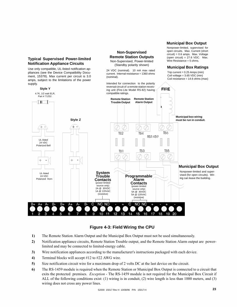
Figure 4-3: Field Wiring the CPU
UL-listed24 VDC
Polarized Horn
UL-listed24 VDC
Polarized Bell
Municipal box wiringmust be run in conduit.
Remote StationTrouble Output
Remote StationAlarm Output
24 VDC (nominal). 10 mA max ratedcurrent. Internal resistance = 1360 ohms(nominal).
Intended for connection to the polarityreversal circuit of a remote station receiv-ing unit (Fire-Lite Model RS-82) havingcompatible ratings.
Non-SupervisedRemote Station OutputsNon-Supervised, Power-limited
(Standby polarity shown)
Trip current = 0.25 Amps (min)Coil voltage = 3.65 VDC (min)Coil resistance = 14.6 ohms (max)
Style Z
4.7K, 1/2 watt ELR,Part # 71252.
Style Y
Typical Supervised Power-limitedNotification Appliance CircuitsUse only compatible, UL-listed notification ap-pliances (see the Device Compatibility Docu-ment, 15378). Max current per circuit is 3.0amps, subject to the limitations of the powersupply.
Municipal Box Ratings
Nonpower-limited, supervised foropen circuits. Max. Current (shortcircuit) = 0.6 amps. Max. Voltage(open circuit) = 27.6 VDC. Max.Wire Resistance = 5 ohms.
Municipal Box Output
Nonpower-limited and super-vised (for open circuits). Wir-ing can leave the building.
Municipal Box Output
1) The Remote Station Alarm Output and the Municipal Box Output must not be used simultaneously.
2) Notification appliance circuits, Remote Station Trouble output, and the Remote Station Alarm output are power-limited and may be connected to limited-energy cable.
3) Wire notification appliances according to the manufacturer's instructions packaged with each device.
4) Terminal blocks will accept #12 to #22 AWG wire.
5) Size notification circuit wire for a maximum drop of 2 volts DC at the last device on the circuit.
6) The RS-1459 module is required when the Remote Station or Municipal Box Output is connected to a circuit thatexits the protected premises. Exception - The RS-1459 module is not required for the Municipal Box Circuit ifALL of the following conditions exist: (1) wiring is in conduit, (2) wire length is less than 1000 meters, and (3)wiring does not cross any power lines.
ProgrammableAlarm
Contacts(power-limitedsource only)
5A @ 30VDC5A @ 120VAC
(resistive)
SystemTrouble
Contacts(power-limitedsource only)
2A @ 30VDC1A @ 120VAC
(resistive)

S2000 15017 Rev H 10/08/96 P/N 15017:H24
Figure 4-4: Connecting the EIA-485 Interface
EIA-485 Interface
Supervised and Power-limited
EIA-485 (+)
EIA-485 (-)
DUMMY-LOADING UNUSED CIRCUITS ON THE CPU
An unused notification circuit must be terminated withone dummy load resistor.
If the Municipal Box Output is not to be used,it must be terminated with a dummy load re-sistor.
4.7K, 1/2-watt ResistorPart # 71245
4.7K, 1/2-watt ResistorPart # 71245
THE EIA-485 INTERFACE
The Sensiscan 2000 communicates with the AFM serial annunciators through the EIA-485 interface on the CPU. Maximumdistance is 6000 feet and maximum resistance is 100 ohms.
TB2

S2000 15017 Rev H 10/08/96 P/N 15017:H 25
b+ b- b+ b- b+ b- b+ b- b+ b- b+ b- b+ b- b+ b-
A B C D E* F* G* H*
A E
B F
C G
D H
Manual Pull Station
UL-listed two-wirePhoto smoke detector 2
UL-listed two-wireIon smoke detector 2
4.7K, 1/2 watt ELR, Part # 71252. 5
1) Initiating device circuits are supervised, power limited and may be con-nected to limited-energy cable, except for initiating devices that require24 VDC power.
2) Use only the compatible, UL-listed two-wire smoke detectors that arelisted in Fire�Lite Document 15384.
3) For connection of four-wire smoke detectors, refer to Section Six.
4) Wire initiating devices according to the manufacturer's instructions pack-aged with each device.
5) For Canada, model F-ELR End-of-Line Resistor Assembly required.
6) Maximum line resistance is 100 ohms.
Typical NFPA Style BInitiating Device Circuit
Supervised and Power-limited
Dummy load all unused circuitswith 4.7K ELR (71245).
*NOTE: IZ-4F contains only circuits A, B, C and D.
FIGURE 4-5 NFPA STYLE B FIELD WIRING OF INITIATING ZONE MODULES

S2000 15017 Rev H 10/08/96 P/N 15017:H26
Manual Pull Station
A B C D E F G H
Two-wire Photo smoke detector
two-wire Ion smoke detector 2
IZ-8F/IZE-AF
Typical NFPA Style DInitiating Device Circuit
Supervised and Power-limited1) Initiating device circuits are supervised, power limited and may be
connected to limited-energy cable, except for initiating devices thatrequire 24 VDC power.
2) Use only the compatible, UL-listed two-wire smoke detectors thatare listed in Fire�Lite Document 15384.
3) For connection of four-wire smoke detectors, refer to Section Six.
4) Wire initiating devices according to the manufacturer's instructionspackaged with each device.
5) The IZ-4F does not support the IZE-AF expander module and there-fore cannot be wired for Style D circuits.
6) Maximum line resistance is 100 ohms.
Dummy load all unused circuitswith a 4.7 ELR (71245).
FIGURE 4-6: STYLE D FIELD WIRING OF IZ-8F INITIATING ZONE MODULE WITH IZE-AFEXPANDER
A E
B F
C G
D H
a+ a- a+ a- a+ a- a+ a- a+ a- a+ a- a+ a- a+ a-
b+ b- b+ b- b+ b- b+ b- b+ b- b+ b- b+ b- b+ b-

S2000 15017 Rev H 10/08/96 P/N 15017:H 27
b+ a+ a- b- b+ a+ a- b- b+ a+ a- b- b+ a+ a- b-
b+ a+ a- b- b+ a+ a- b- b+ a+ a- b- b+ a+ a- b-
E F G H Optional ICE-4F Indicating Circuit Expander. Positions E, F, G, and Hare active only with this board installed.
4.7K, 1/2 watt ELR,Part # 71252. 5
Jumperunusedcircuits
Jumperunusedcircuits
UL-listed24 VDC
Polarized Horns
UL-listed24 VDC
Polarized Bells
TypicalNFPA Style Y
Notification ApplianceCircuit
TypicalNFPA Style Z
Notification ApplianceCircuit
Cut this diode for California Code
FIGURE 4-7: NFPA STYLE Y/Z FIELD WIRING OF THE IC-4F INDICATING CIRCUIT MOD-ULE AND ICE-4F EXPANDER
1) Notification appliance circuits are supervised, power limited and may be connected to limited-energy cable.
2) Use only compatible, UL-listed notification appliances that are listed in Document 15384.
3) Wire notification appliances according to the manufacturer's instructions packaged with each device.
4) Max current per circuit is 3.0 amps, subject to the limitations of the source of power (MPS-24AF/MPS-24AFE, MPS�24BF/MPS-24BFE, or AVPS-24F/AVPS-24FE).
5) For Canada, model F-ELR End-of-Line Resistor Assembly is required.
6) Size wiring for a maximum voltage drop of two volts at the last device on the circuit.
7) The IC-4F is California Code programmable (microprocessor Rev. B or higher of IC-4F). To program for California Code, cutdiode D35.
8) Cut jumper JP1 and JP2 to separately power notification appliance circuits 1 & 2 or 3 & 4. Separate 3 amps max. powersupplies must be tied to J5 & J6.
IC-4F/ICE-4F
A B C D
A E
B F
C G
D H
D35
J5 J6
JP2

S2000 15017 Rev H 10/08/96 P/N 15017:H28
* Optional CRE-4F Control Relay Expander. Positions E, F, G and Hare active only with this board installed.
These Form-C gold-plated, silver alloy relay contacts are formedium duty switching and are not intended for Motor Con-trol or Pilot Duty.
UL contact ratings are 5 amps @ 125 volts AC (resistive) or30 volts DC (resistive) and 2 amps @ 125 volts AC (induc-tive).
Activation of a CR-4F or CRE-4F relay occurs automati-cally when an alarm is detected on a selected (programmed)Initiating Device Circuit.
no nc c no nc c no nc c no nc c
E F G H
no nc c no nc c no nc c no nc c
A B C D
A E
B F
C G
D H
★
★
★
★Nonpower-limited and power-limited wiring must have a minimumdistance of 0.25" wire to wire and must enter and exit from differentknockouts. If this module is used to drive nonpower-limited andpower-limited circuits, please follow the instructions below.
1) Skip a set of dry contacts to maintain the 0.25" required spacebetween power-limited and nonpower-limited circuits. The wiringof this module must follow UL Power-limited Wiring Requirements.
OR
2) If this module is needed to drive power-limited and nonpower-limited relays that are next to each other, refer to the figure to the leftshowing a typical connection.
NO
NO
NC
NC
NC
NO
C
C
CNO
Relay 1
Relay 2
Relay 3
Relay 4 NCC
Power-limited Circuit
Power-limited Circuit
Nonpower-limited Circuit
Nonpower-limited Circuit
no connection
Typical Form-C Control Relay in Standby Position
FIGURE 4-8: FIELD WIRING OF THE CR-4F CONTROL RELAY MODULE AND THE CRE-4FCONTROL RELAY EXPANDER
Note: Refer to the power-limited label located on the FACP door.Make a notation on the label for each circuit being employed asa nonpower-limited circuit. (Refer to the example on the label).

S2000 15017 Rev H 10/08/96 P/N 15017:H 29
SECTION FIVE: THE POWER SUPPLIES
Main Power Supply BellPower Harness
(71093)Blue to Bell Power (+)Black to Bell Power (-)
Three cables complete the electrical connection between the CPU and the main power supply.
CPU(BottomView)
Power Ribbon(71085)
Connects to P3on the main
power supplyMain Power Harness
(71086) to P2 on the main power
supply

S2000 15017 Rev H 10/08/96 P/N 15017:H30
The MPS-24AF/MPS-24AFE Main Power Supply is capable of powering the control panel continuously during standby andalarm conditions. A total of 3.0 amps (internal0 @ 24 VDC regulated is available from the main power supply for operatingthe system during Standby conditions. No more than 6 amps @ 24 VDC can be drawn from the MPS-24AF.
Figures 5-1 and 5-2 illustrate connections for primary and secondary power to the MPS-24AF Main Power Supply, as wellas terminal and harness connections for the control panel.
CONNECTING THE PRIMARY POWER SOURCE
Primary power required for the MPS-24AF is 120 VAC, 50/60 Hz, 1.8 amps and primary power for the MPS-24AFE is 220/240 VAC, 50/60 Hz, 0.9 amps. With the breaker at the main power distribution panel turned off, remove the plastic insulat-ing cover from Terminal Block TB1 on the main power supply and connect the system primary power source. Connect theservice ground to TB1 Terminal 2 and ground the power supply assembly to the cabinet with a Chassis Ground cable (71073)to TB1 Terminal 1. Connect the primary Neutral line to TB1 Terminal 4 and the primary Hot line to TB1 Terminal 6. Aftercompletion of these connections reinstall the plastic insulating cover over the terminal strip. Leave the main power breakeroff until installation of the entire system is complete.
CONNECTING THE SECONDARY POWER SOURCE (24 VDC)Secondary power (batteries) is required to support the system during loss of primary power. These batteries reside in thecontrol panel cabinet, or in a separate R45-24 Remote Battery Charger cabinet which can be mounted up to 20 feet awayfrom the control panel (for connection of an R45-24, refer to Figure 5-6).
Connect the Battery Positive Cable (71071) to TB2 Terminal 1 (+) and the Battery Negative Cable (71072) to TB2 Terminal2 (-). Do not connect the Battery Interconnect Cable (Part Number 71070) at this time. This connection will be made justafter initial primary system power-up.
FOUR-WIRE SMOKE DETECTOR POWER (24 VDC)Up to one amp of current for four-wire smoke detectors can be drawn from TB3 Terminals 1 (+) and 2 (-). Power is removedfrom these terminals during system reset. This 24 VDC regulated four-wire smoke detector power is power limited but mustbe supervised via an UL-listed end-of-line power supervision relay. The power supervision relay is energized by the four-wire power circuit and its contact must be connected in series with an initiating device circuit.
NOTIFICATION APPLIANCE POWER (24 VDC)Up to 3 amps of regulated power-limited current for powering notification appliances can be drawn from TB3 Terminals3(+) and 4(�). Power is not removed from these terminals during system reset. If a resettable power circuit is desired, cutJP5 on the MPS-24AF (Note that a maximum of 2 amps is available with JP5 cut.) Note: On the Main Power Supply BellPower Harness, the fork lugs must be cut off and wires stripped for connection to the MPS-24AF.
ANNUNCIATOR POWER (24 VDC)AFM Annunciators can be powered either from the four-wire smoke detector output or the notification appliance poweroutput. Both outputs provide filtered, regulated, power-limited source required by the annunciators. The power run to theannunciators is supervised by the annunciator (Loss of Communications error).
SYSTEM HARNESS CONNECTIONS
Internal power for the system is provided via the power harness. Connect this harness from P2 on the main power supply tothe CPU. This same power can be fed to other boards or modules requiring internal power. Signaling between the CPU andthe main power supply is accomplished through connection of the Power Ribbon (71085) to P3 on the MPS-24AF.
5.1 THE MPS-24AF/MPS-24AFE MAIN POWER SUPPLY

S2000 15017 Rev H 10/08/96 P/N 15017:H 31
Cut R27 to disableEarth FaultDetection.
Four-Wire Smoke Detector/Annunciator Power24 VDC (20.4-26.4, 200 mV ripple), 1 amp max. Filtered, regulated and resettable.Power-limited but must be supervised via a UL approved Power Supervision Relay.
Notification Appliance/Annuncia-tor PowerPower-limited, filtered, regulated,non-resettable , 3 amps (in alarm)max. Power is supervised by outputmodule (such as an ICM-4F) in theSensiscan 2000.
FIGURE 5-1: FIELD WIRING THE MPS-24AF/MPS-24AFE POWER SUPPLY
Power Harnesses (P2, P4)
Power Ribbon Connector
+ -+- Secondary Power
27.6 VDC, supervised and power-limited.Fast charge = 2 amps, trickle charge = 20 mA.
Battery -Battery +
EarthGroundConnect tochassis via aGrounding CableAssembly.
Ground
Primary Power120 VAC, 50/60 Hz, 1.8 amps for MPS-24AF220/240 VAC, 50/60 Hz, 1.8 amps for MPS-24AFE
Neutral Out Hot In
Neutral In Hot Out
Battery Fuse
* Cut JP5 to convertNotification Appliance
power (TB3 Terminals 3-4)
to a resettable,2-amp maximum
circuit.
DO NOT CUT JP2.
When employing anR45-24/R45-24ERemote BatteryCharger, removeJumper JP-1.
LED IndicatorsGround FaultBattery FailAC Power Fail(not used)
AVPS-24FSupervisory CableConnector

S2000 15017 Rev H 10/08/96 P/N 15017:H32
CPU(bottom view)
Bottomview
of ICM-4For ICE-4F
If powering a notification circuit module from themain power supply, connect the Auxiliary Bell PowerHarness (71091) from J6 on the CPU to J5 on the ICM-4F or ICE-4F. See Section 6.9 for more information.
Connector orientation
7-position end
Note position of RedWire at 8-position end
Power Ribbon(71085)
Main PwerSupply BellPowerHarness (71093)
Blue wirePower Harness
(71086)Connect to P2 or P4.
(ICM-4F)
(ICE-4F)
FIGURE 5-2 HARNESS CONNECTIONS FOR THE MPS-24A
+ -
MPS-24AF/MPS-24AFE

S2000 15017 Rev H 10/08/96 P/N 15017:H 33
5.2 THE MPS-24BF/MPS-24BFE MAIN POWER SUPPLY
Note: The MPS-24BF has been designed to support single-cabinet row systems only.
This amounts to enough power for the CPU and up to three other modules as a maximum.
The MPS-24BF Main Power Supply is a supply capable of powering the system continuously during standby and alarmconditions. A total of 750 mA @ 24 VDC regulated is available for operating the system during Standby conditions.
Figures 5-3 and 5-4 illustrate connections for primary and secondary power to the MPS-24BF Main Power Supply, as wellas terminal and harness connections.
CONNECTING THE PRIMARY POWER SOURCE
The MPS-24BF requires 120 VAC, 50/60 Hz, 1.8 amps primary power and the MPS-24BFE requires 220/240 VAC, 50/60Hz, 0.9 amps. With the breaker at the main power distribution panel turned off, remove the plastic insulating cover fromTerminal Block TB1 and connect the system primary power source. Ground Cable per NEC requirements. Ground thepower supply assembly to the cabinet with a Chassis Ground cable (71073) to TB1 Terminal 2. Connect the primary Neutralline to TB1 Terminal 3 and the primary Hot line to TB1 Terminal 4. Do not route 120 VAC wiring in the same conduit asother control panel circuits. After completion of these connections reinstall the plastic insulating cover over the terminalstrip. Leave the main power breaker off until installation of the entire control panel is complete.
CONNECTING THE SECONDARY POWER SOURCE (24VDC)Secondary power (batteries) is required to support the system during loss of primary power. These batteries reside in thecontrol panel cabinet. Connect the Battery Positive Cable to TB3 Terminal 1 (+) and the Battery Negative Cable to TB3Terminal 2 (-). Do not connect the Battery Interconnect Cable at this time. This connection will be made just after initialprimary system power-up.
EARTH FAULT DETECTION
The MPS-24BF automatically employs detection of earth faults in the system (unless Resistor R55 is removed).
FOUR-WIRE SMOKE DETECTOR POWER (24VDC)Up to 200mA of current for 24 VDC four-wire smoke detectors can be drawn from TB2 Terminals 1 (+) and 2 (-). Power isremoved from these terminals during system reset (unless Jumper JP1 is removed). This regulated four-wire smoke detectorpower is power-limited but must be supervised via a UL-listed Power Supervision Relay. The power supervision relay isenergized by the four-wire power circuit and its contact must be connected in series with an initiating device circuit.
ANNUNCIATOR POWER (24VDC)Up to 200mA of current suitable for powering an AFM-16ATF or AFM-32AF Annunciator can be drawn from TB2 Termi-nals 1 (+) and 2(-). The power is regulated, power-limited and is supervised by the annunciator.
NOTIFICATION APPLIANCE POWER (24 VDC)Up to 2.0 amps of regulated power-limited current for powering Notification appliances can be drawn from TB2 Terminals3 (+) and 4 (-). Power is not removed from these terminals during system reset. Do not connect any type of serialannunciator (such as an AFM) or any device requiring filtered 24 VDC power to this circuit or damage may result!
SYSTEM HARNESS CONNECTIONS
Internal power for the system is provided via the Power Harness (71086). Connect this harness from P2 on the MPS-24BFto the CPU. Signaling between the CPU and the main power supply is accomplished through connection of the PowerRibbon (71085) to P3 on the MPS-24BF.

S2000 15017 Rev H 10/08/96 P/N 15017:H34
* Cut JP1 to make Four-WireSmoke Detector/AnnunciatorPower on TB2 Terminals 1 and 2a non-resettable circuit.
FIGURE 5-3 THE MPS-24BF MAIN POWER SUPPLY
Cut JP2 to disable the batterycharger when employing the R45-24 Remote Battery Charger.
Supervisory Cable tooptional AVPS
LED Indicators
Ground FaultBattery FailAC Power Fail
AC CircuitBreaker
Chassis GroundConnect to chassis witha Grounding Cable As-sembly (Cable # 71073).
Earth Ground
Primary Power120 VAC, 1.8 amps max for MPS-24BF220/240 VAC, 0.9 amps max for MPS-24BFE
Neutral Hot
Cut R55 to disableEarth Fault Detection
-+ Four-Wire Smoke Detector/Annunciator Power
+ 24 VDC (20.4-26.4, 200 mV ripple), 200 mA max.Filtered, regulated and resettable*. Power-limited butwhen used for four-wire detectors, must be super-vised by a UL-listed Power Supervision Relay.
Notification Appliance power (see Caution below)+ 24 VDC power-limited, RMS-regulated, non-resettable,2.0 amps (in alarm) max. Power is supervised by outputmodule such as an IC-4. This output is not suitable forpowering annunciators.
+
-CAUTION: The +24 VDC provided on TB2 Terminal 3 ispower-limited only when used with the minus return onTB2 Terminal 4. Do not use the minus return on TB2 Ter-minal 2 with the +24 VDC power on TB2 Terminal 3.
Secondary Power27.6 VDC, 6.5 to 17 AH. Supervised and power-limited.Fast charge =750mA max., trickle charge = 20 mA (typ).
Battery +Battery -

S2000 15017 Rev H 10/08/96 P/N 15017:H 35
FIGURE 5-4 MPS-24BF/MPS-24BFE H ARNESS CONNECTIONS
CPU(bottom view)
7-position end
Power Harness(71086)
Connect to P2
Note position of RedWire at 8-position end.
Blue wire Black wire
Red Wire
Power Harness Connector Orientation
Power Ribbon(71085)
+ -
Main PowerSupply BellPowerHarness (71093)
Connect to J5 onthe CPU-2000.

S2000 15017 Rev H 10/08/96 P/N 15017:H36
1 2
Hot
-
+
Neutral
Earth Ground OutConnect to TB1 Terminal 1on next AVPS-24F.
Earth Ground InConnect to chassis or EarthGround Terminal on themain power supply.
Last AVPS-24FFirst AVPS-24FTo P5 on MPS-24AF;or to P4 on the MPS-24BF.
+ -
Black wire
Blue wire
Auxiliary BellPower Harness
24 VDC Bell PowerUnfiltered, unregulated, power-limited (3.0 amps max). Use AuxiliaryBell Power Harness to provide power to notification circuit modules(connect to J5 on IC-4F or ICE-4F).
For multipleAudio Visual
Power Supplies
Secondary Power(24 VDC Batteries)
Connect to:MPS-24AF: TB2-1 (+) and TB2-2 (-)MPS-24BF: TB3-1 (+) and TB3-2 (-)
Primary Power120 VAC for AVPS-24F
220/240 VAC for AVPS-24FE
Connect to:MPS-24AF: TB1-5 (Neutral) and TB1-7 (Hot)MPS-24BF: TB1-3 (Neutral) and TB1-4 (Hot).
TroubleLED
For the first or only AVPS-24F in a Sensiscan2000, connect the AVPS-24F Trouble Cable(71033) to P5 on the MPS-24AF or P4 on theMPS-24BF for supervision. Otherwise con-nect as illustrated below.
TB2
TB1
P3
Figure 5-5 Field Wiring of the Optional Audio Visual Power Supplies (AVPS-24F/AVPS-24FE)

S2000 15017 Rev H 10/08/96 P/N 15017:H 37
Figure 5-6 Connecting the R45-24 Remote Battery Charger
1 2 3 4
- + - +
R45-24
+ -
Primary Power SourceHot Neutral
PS-1255012 VDC55-AHBattery
PS-1255012 VDC55-AHBattery
IMPORTANT!1) Cut JP1 to disable on-board charger on the MPS-24AF.2) Cut JP2 to disable on-board charger on the MPS-24BF.
TB2-6PS-12550Battery
PS-12550Battery
TB2-2
TB2-1 TB2-5
MPS-24AF MPS-24BF
THE R45-24/R45-24E REMOTE BATTERY CHARGER
When the secondary requirements demand batteries that cannot be adequately charged by the main power supply employed,an R45-24 Remote Battery Charger must be used. The R45-24 mounts in its own cabinet, up to 20 feet away (must be in thesame room as the control panel). The R45-24 is capable of charging 55 AH PS-12550 batteries, which are also contained inthe charger cabinet. For more information refer to the R45-24 Product Installation Drawing packaged with each unit.
CONNECTING THE PRIMARY POWER SOURCE
The R45-24 requires 120 VAC, 50/60 Hz primary power and the R45-24E requires 220/240 VAC, 50/60 Hz primary power.With the breaker at the main power distribution panel turned off, connect the primary Hot line to Terminal 1 on the R45-24and the primary Neutral line to Terminal 2. All connections between the Sensiscan 2000 and the R45-24 must be made inconduit, using #12 AWG wire. Do not route VAC wiring in the same conduit as other Sensiscan 2000 circuits. Leave themain power breaker off until installation of the entire system is complete.
CONNECTING THE SECONDARY POWER SOURCE (24VDC)Do not connect AC power or batteries until the system is completely wired and ready for testing. Refer to Wiring Diagramand instructions for the Fire-Lite R45-24 remote Battery Charger.
24 VDC. (supervised). Maximum charge current for standby batteries is 2 amps(fast charge) or 20mA (trickle charge). Use #12 AWG wire in conduit (20 feet orless, in same room).
+
-

S2000 15017 Rev H 10/08/96 P/N 15017:H38
SECTION SIX: APPLICATIONS
6.1 WATERFLOW ALARM
A waterflow alarm device may be connected to an IZ Series Initiating Zone Module circuit provided that the circuit isprogrammed to activate at least one notification appliance circuit and one of the following conditions are met:
� The initiating Device Circuit is programmed for waterflow operation
OR
� the notification appliance circuit is programmed as non-silenceable.
6.2 SUPERVISORY SERVICE
Normally open supervisory devices may be connected to any Initiating Zone Module circuit provided that the circuit isprogrammed for supervisory operation. This circuit must be dedicated to supervisory devices.
6.3 CENTRAL STATION
The Sensiscan 2000 can be employed as a protected premises Control Unit when used in conjunction with a compatible,UL- listed electrically-activated transmitter or when used in conjunction with a compatible, UL-listed digital alarm commu-nicator such as the 911A. (See Figure 6-1)
6.4 DIGITAL ALARM COMMUNICATOR TRANSMITTERS (DACT)The Fire Alarm Control Panel (FACP) will support a Digital Alarm Communicator Transmitter (DACT) provided that thepanel is configured and programmed for DACT operation. Software P/N 73452 (or higher) will support DACT�s that areactivated via relay contacts (911A), while Software P/N 73611 (or higher) will support the UDACT-F via the EIA-485Annunciator Port.
The FACP must be programmed for DACT operation (see the Extended Programming Section). Programming the FACP forDACT operation will delay the reporting of an AC loss condition for approximately eight hours (Software P/N 73452 orhigher) and modify the EIA-485 Annunciator Port protocol (Software P/N 73611 or higher) for UDACT-F operation.
The modified protocol is compatible with the AFM and LDM Annunciators. Annunciators and a UDACT-F can be con-nected to the EIA-485 Annunciator Port simultaneously. However, the modified EIA-485 protocol alters the assignment ofthe first eight yellow annunciator LED's as shown in the table on the following page.

S2000 15017 Rev H 10/08/96 P/N 15017:H 39
elbuorTtnioPwolleY()DEL
N/PerawtfoSdna25437
rewol
rehgihdna11637N/PerawtfoS
tuohtiWF-TCADU
F-TCADUhtiW
1 elbuorTmetsySelbuorTmetsyS)ssolCAssel(
elbuorTmetsyS)ssolCAssel(
2 decneliSlangiS decneliSlangiS decneliSlangiS
3 desUtoN desUtoN desUtoN
4 yrosivrepuS yrosivrepuS yrosivrepuS
5tiucriCgnitacidnI
elbuorT1tiucriCgnitacidnI
elbuorT1tiucriCgnitacidnI
elbuorT1
6tiucriCgnitacidnI
elbuorT2tiucriCgnitacidnI
elbuorT2tiucriCgnitacidnI
elbuorT2
7eiTlapicinuM
elbuorTeiTlapicinuM
elbuorTdnG/yrettaBwoL
tluaF
8 elbuorTlenaP liaFCA liaFCA
Annunciators and a UDACT-F can be connected to the EIA-485 Annunciator Port simultaneously. However, the modifiedEIA-485 protocol alters the assignment of the first eight yellow annunciator LED�s as follows:
seciveDdellatsnI
F-TCADU )1etoN(rotaicnunnA
noitarugifnoC noisivrepuS noitarugifnoC noisivrepuS
F-TCADUylnO
timsnarT/evieceR 584-AIEaiV
F-TCADUdna
rotaicnunnA
timsnarT/evieceR 584-AIEaiV1sserddA
ylnOevieceRdesivrepuS-nU
ylnOevieceRF-TCADUaiVliaFmmoC
)2etoN(tuptuO
1sserddAtimsnarT/evieceR
584-AIEaiV
timsnarT/evieceR 584-AIEaiV1sserddA
ylnOevieceR584-AIEaiV
)3etoN(
1) Additional annunciators may be employed in the Receive Only Mode. The wiring to these annunciators will besupervised only if the power and the EIA-485 circuits are wired sequentially and the Receive/Transmit device isconnected last.
2) The UDACT-F's Comm Fail Output (TB3, pin #2) must be connected to the AUX Trouble Input on the main powersupply (P5, pin #1 on MPS-24AF or P4, pin #1 on MPS-24B). See connection diagrams.
3) The power and the EIA-485 circuits are wired sequentially (the FACP connects to the annunciator and the annun-ciator connects to the UDACT-F).
The FACP must be programmed for an annunciator whenever it's connected to a UDACT-F since the UDACT-F receives theFACP status on the EIA-485 Annunciator Port. If the FACP is connected to both annunciators and a UDACT-F, all devicesexcept one must be configured as receive only. Refer to the table below for configuration and supervision arrangements.

S2000 15017 Rev H 10/08/96 P/N 15017:H40
Figure 6-1: UDACT-F Mounting in CHS-4
CPU-2000
UDACT-F
CHS-4
NylonSupportPosts
Aluminum Standoffand screw
Nylon &AluminumStandoff
GroundStrap
INSTALLING THE UDACT-FRemove all power from the control panel by disconnecting AC and batteries. Install the three supplied nylon support postsfor the top and bottom left of the UDACT-F, one aluminum/nylon and one aluminum standoff in the CHS-4 chassis slot inwhich the UDACT-F is to be installed (refer to Figure 6-1). Position the UDACT-F on the standoffs and secure on alumi-num standoff with a #6-32 screw. Alternatively, the UDACT-F may be mounted remotely using an ABS-8RF enclosure.Ferrite cores are required for this application. Refer to the UDACT-F Manual, Document 50049 for more information.
Connect the communication line between the EIA-485 terminal block on the CPU-2000 and TB1 terminals 3 and 4 on theUDACT-F being certain to observe polarity (refer to the Document 50049). Recommended wire is 12 AWG to 18 AWGtwisted pair. If no other devices are connected to the EIA-485, install a 120 ohm end-of-line resistor across UDACT-F TB1terminals 3 and 4.
Connect the supplied Ground Strap from the UDACT-F Earth Ground terminal on TB3 to the CHS-4 chassis. Connect24VDC filtered, regulated, non-resettable power to TB1 terminals 1 and 2 on the UDACT-F (refer to Document 50049).

S2000 15017 Rev H 10/08/96 P/N 15017:H 41
6.5 CONNECTION OF A 911A DIGITAL COMMUNICATOR
Power Requirements: 26.6VDC minimum, 30 mA in Normal; 138 mA while communicating; 166.8 mA with alarm &trouble relays while communicating.
Retard time and Reset time must be programmed for zero second when connecting the alarm initiating circuit to an existingcontrol panel.
For more detailed instructions and connection and power information, refer to the Noti-Fire 911A manual, Document #74-06200-005-A.
The Noti-Fire 911A Digital Alarm Communicator Transmitter (DACT) is a three-zone module designed for use with theSensiscan 2000 to provide for off-premises monitoring of this fire alarm control panel. For stand-alone installations, use the911AC kit that includes a transformer and an enclosure(s) for both the 911A and the transformer. The 911A is self-poweredin this mode and is triggered by the alarm and/or trouble contacts received from the control panel. It communicates with adigital receiver by means of one of two transmission formats, BFSK or Pulsed Fast Single Round format.
MPS-24AF
(+) 24 VDC
(+) 27.6 VDC
Common
CPU
TroubleAlarm
911AWiring between the FACPand 911A must be in conduit.
UPC A119 SPM
mralAyllamron
nepostcatnoc
41-1BT 7dna6
51-1BT 9dna8
elbuorTyllamron
nepostcatnoc
9-1BT 01
11-1BT 11
CDV42+ 2 3-2BT
nommoC 4 4-2BT

S2000 15017 Rev H 10/08/96 P/N 15017:H42
6.6 MS-5012 AS A DACTThe MS-5012 may be used as a slave communicator to a master FACP. In slave configuration, five channels may betriggered by the relay outputs of the master panel. Zone 1 is used for General Alarm, Zone 2 is used for general trouble, Zone4 is used for supervisory. Zone 3 and 5 may be programmed to match the FACP relay function.
Figure 6-2A: Connecting the MS-5012 as a DACT
NOTES:
1) Reference the MS-5012 manual for additional information.
2) Program the MS-5012 for slave application.
AC wiring for the DACT/FACPmust be connected to the samecircuit.
1 2 3 4 5 6 7 8 9 10 1112 1314 15 16 17 18 19 20
-
+ 12VDCBattery2-7AH
Red
Black120 VAC
HOT
Neutral
GroundBlack
White
Green
yellow
yellow
1 2
TB2
TB3
TB1
RESET SILENCE MODE
ALARM
AC POWER TROUBLE
SUPERVISORY
Primary Active
Secondary Active
KissoffJ2
J3
Modular CableP/N MCBL-6
Secondary Phone Line
Primary Phone Line
Alarm
Trouble
CPU
1
2
3
4
5
6
7
8
9
10
11
12
13
14
2105-SM draobrehtoM
mralA1-2BT 51-1BT
2-2BT 41-1BT
elbuorT3-2BT 01-1BT
4-2BT 9-1BT
S2000 15017 Rev H 10/08/96 P/N 15017:H 43
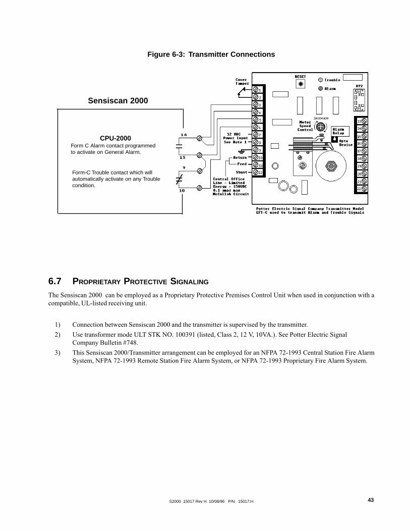
Figure 6-3: Transmitter Connections
1) Connection between Sensiscan 2000 and the transmitter is supervised by the transmitter.
2) Use transformer mode ULT STK NO. 100391 (listed, Class 2, 12 V, 10VA.). See Potter Electric SignalCompany Bulletin #748.
3) This Sensiscan 2000/Transmitter arrangement can be employed for an NFPA 72-1993 Central Station Fire AlarmSystem, NFPA 72-1993 Remote Station Fire Alarm System, or NFPA 72-1993 Proprietary Fire Alarm System.
Form-C Trouble contact which willautomatically activate on any Troublecondition.
CPU-2000Form C Alarm contact programmedto activate on General Alarm.
Sensiscan 2000
6.7 PROPRIETARY PROTECTIVE SIGNALING
The Sensiscan 2000 can be employed as a Proprietary Protective Premises Control Unit when used in conjunction with acompatible, UL-listed receiving unit.

S2000 15017 Rev H 10/08/96 P/N 15017:H44
6.8 TEE-TAPPING
One Tee-Tap will be allowed on Style Y notification appliance circuits if a 10 K End-of-Line Resistor (Part # 71274) is usedon each branch as shown in Figure 6-4. Note: This application is not recommended by Factory Mutual (FM).
Figure 6-4: Tee-Tapping Notification Appliance Circuits
StandardStyle Y
IC-4F Notification CircuitModule or ICE-4F Expander
Tee-TappedNotification Appliance
Circuit
4.7K ELR(Part # 71252)
Listed10K ELR
(Part # 71274)
Listed10K ELR
(Part # 71274)

S2000 15017 Rev H 10/08/96 P/N 15017:H 45
6.9 FOUR-WIRE SMOKE DETECTORS
Initiating devices requiring 24 VDC operating power can be wired as illustrated in Figures 6-4 and 6-5.
UL-Listed PowerSupervision
Relay
UL-listed 24 VDCFour-Wire Smoke Detectors
IZ-4F orIZ-8F
Initiating DeviceCircuit
UL-listed 24 VDCFour-Wire Smoke Detectors
24VDC PowerSupply
Power-limited,UL listed for FireProtectiveSignaling
24VDC PowerSupply
Power-limited,UL listed for FireProtectiveSignaling
IZ SeriesInitiating Device
Circuit
Figure 6-4:
Employing Four-Wire Smoke Detectors (Style D)
All connections are supervised and power-limited
UL-Listed PowerSupervision
Relay
where:
Notes on Style B and Style D field wiring:
1) The Power Supervision Relay coil leads must be connected to the last detector base 24V screw terminal.
2) Calculation of the maximum allowable resistance in the 24VDC detector power wiring:
RMAX = (20.6 - VOM)(N)(IS) + (NA)(IA) + (IR)
RMAX �is the maximum total resistance of the 24V power circuits.VOM � is the minimum operating voltage of the detector or end of line relay, whichever is greater, in volts.N � is the total number of detectors on the 24V supply loop.IS � is the detector current in standby.NA � is the number of detectors on the 24V power loop which must function at the same time in alarm.IA � is the detector current in alarm.IR � is the end-of-line relay current.
4.7K 1/2-watt End-Of-Line Resistor,
Part #71245
Figure 6-5: Employing Four-Wire Smoke Detectors (Style B)
All connections are supervised and power-limited
MPS-24AF TB3 Term. 1 (+) & 2 (-)MPS-24BF TB2 Term. 1 (+) & 2 (-)
MPS-24AF TB3 Term. 1 (+) & 2 (-)MPS-24BF TB2 Term. 1 (+) & 2 (-)

S2000 15017 Rev H 10/08/96 P/N 15017:H46
Figure 6-6: Typical Supply/Notification Circuit Configurations
CPUModule
J5
CPUModule
J5
J6
J5
IC-4F
CPUModule
J5
AVPS-24F IC-4F
J5
CPUModule
IC-4F
ICE-4F
J5
J6
J5
J6
J5
Bottom view of theIC-4F/ICE-4F
mainpowersupply
mainpowersupply
mainpowersupply
mainpowersupply
These two notification appli-ance circuits share the totalmain power supply current.
These four notification appli-ance circuits share the total3.0 amps of current on theAVPS-24F.
These sixNotification appliancecircuits share the total mainpower supply current.
6.10 NOTIFICATION APPLIANCE CIRCUIT POWER CONFIGURATIONS
The total current drawn from a notification appliance circuit cannot exceed 3.0 amps (subjectto the limitations of the power supply). Figure 6-6 illustrates some of the typical powersupply/notification appliance circuit configurations possible with the Sensiscan 2000.
These two notification appliance cir-cuits share the total main powersupply current.
These tenNotification appliancecircuits share the total main powersupply current.

S2000 15017 Rev H 10/08/96 P/N 15017:H 47
Whenever supplying an IC-4F or ICE-4F module withtwo different sources of power (as in the above illus-tration), cut jumper JP1 and JP2.
These four notification appliance cir-cuits share 3.0 amps of one AVPS-24F.
These eight notification appliance cir-cuits share 3.0 amps of one AVPS-24F.
These four notification appliance cir-cuits share 3.0 amps of one AVPS-24F.
These four notification appliance cir-cuits share 3.0 amps of one AVPS-24F.
These two notification appliance cir-cuits share 3.0 amps of one AVPS-24F.
These two notification appliance cir-cuits share total current of the mainpower supply.
These two circuits share 3.0 ampsof one AVPS-24F.
These two circuits share 3.0 ampsof one AVPS-24F.
MainPowerSupply
J5 CPUModule
AVPS
AVPSIC-4F
J6
IC-4F
J5
J5
J5
ICE-4F
AVPSJ5
IC-4F
IC-4FAVPS
MainPowerSupply
AVPS
AVPSIC-4F
J6
J5
CPUModule
J5
J5

S2000 15017 Rev H 10/08/96 P/N 15017:H48
EmergencyAlert
Acknowledge
SignalSilence
ResetPresignal
Inhibit
6.11 REMOTE COMMAND INPUTS FOR THE SENSISCAN 2000The function of Acknowledge, Signal Silence, and Reset can be executed from remote switches. The switches are wired toIZ-8F circuits which must be programmed for this special operation. Additional functions are outlined below, can also beaccomplished through IZ-8F circuits.
Presignal Inhibit: IZ-8F zone 1. Program zone as non-alarm and supervisory. This command is used to inhibit presignaloperation. Upon entering presignal, the CPU checks zone 1 on all IZ-8F modules. If the zone is active (shorted), all presignalor PAS operations will be ignored.
Emergency Alert: IZ-8F zone 5. Program zone as non-alarm and supervisory. Use as an evacuation signal for tornados,bomb-scares and other non-fire emergency situations. If the control panel is not in alarm, activation (short) on zone 5 willactivate all notification appliance circuits and output relays, that are mapped to zone 5, with a steady signal. ProgrammedMarch Time or Temporal code is ignored. A fire alarm will take priority over an emergency alert. Notification appliancecircuit used for fire must be programmed for MTC or Code 3 operation. Emergency Alert is for local signalling only, do notmap to "Remote Signalling/Municipal Tie" outputs.
Acknowledge: IZ-8F zone 6. Program circuit as non-alarm and supervisory. Use to remotely execute an Acknowledgecommand without the need of an AFM-16ATX annunciator.
Signal Silence: IZ-8F zone 7. Program circuit as non-alarm and supervisory. Use to remotely execute the Signal Silencecommand without the need of an AFM-16ATX annunciator.
System Reset: IZ-8F zone 8. Program circuit as non-alarm and supervisory. Use to execute the Reset function without theneed of an AFM-16ATX annunciator.
Function only asregular Alarm
zones
Figure 6-7: Remote Command Input Connections
1) Initiating circuits used as command circuits are supervised, power-limited, and may be connected to limited-energy cable.
2) Maximum line resistance allowed due to wiring is 100 ohms.

S2000 15017 Rev H 10/08/96 P/N 15017:H 49
Figure 6-8: Remote Presignal Inhibit, Emergency Alert,
Acknowledge, Signal Silence and System Reset Switches (Style B).
1) Switches used to control Presignal Inhibit, Acknowledge,Signal Silence or System Reset must be key operated,located within a locked cabinet, or arranged to provideequivalent protection against unauthorized use.
2) Switches must be UL listed to switch 30 VDC at 50mA.
3) If a key operated switch is used, the key should be re-movable in both open and closed positions, when usedfor Presignal Inhibit. The keys should be removable inthe open position only when used for Acknowledge, Sig-nal Silence or System Reset.
4) The Presignal Inhibit, Emergency Alert, Acknowledge,Signal Silence or System Reset functions can be controlledby a relay contact from a CR-4F/CRE-4F Relay Module,which can be operated from switches on AFM-16ATXAnnunciators.
5) Locate Acknowledge, Signal Silence and System Resetswitches adjacent to a system annunciator so that systemstatus is available to the operator.
6) Remote Command Circuits are supervised and power lim-ited. Maximum wire resistance per circuit is 100 ohms.Circuits wired for Style B operation require a 4.7K End-Of-Line Resistor (P/N 71252) at the end of the line.
4.7K ELRP/N 71252
Presignal InhibitSwitch
B+ B-
B+ B- B+ B- B+ B- B+ B- B+ B- B+ B- B+ B- B+ B-
A B C D E F G Hñ ñ ñ ñ ñ ñ ñ ñ
EEmergency Alert
FAcknowledge
GSignal Silence
HSystem Reset
APresignal Inhibit
B(standard zone)
C(standard zone)
D(standard zone)
IZ-8F
Dummy load all unusedcircuits with 4.7K ELR,
Part # 71245

S2000 15017 Rev H 10/08/96 P/N 15017:H50
Figure 6-9: Remote Presignal Inhibit, Emergency Alert,
Acknowledge, Signal Silence and System Reset Switches (Style D).
Presignal InhibitSwitch
Jumper all unusedcircuits as shown
Style D
B+ B-
A+ A-
Switches used to control Presignal Inhibit, Acknowledge, Signal Silence or System Reset must be key operated, locatedwithin a locked cabinet or arranged to provide equivalent protection against unauthorized use.
1) Switches must be UL-listed to switch 30 VDC at 50mA.
2) If a key operated switch is used, the key should be removable in both open and closed positions when used forPresignal Inhibit. The keys should be removable in the open position only when used for Acknowledge, SignalSilence or System Reset.
3) The Presignal Inhibit, Emergency Alert, Acknowledge, Signal Silence or System Reset functions can be controlledby a relay contact from a CR-4F/CRE-4F Relay Module, which can be operated from switches on AFM-16ATXAnnunciators.
4) Locate Acknowledge, Signal Silence and System Reset switches adjacent to a system annunciator so that systemstatus is available to the operator.
5) Remote Command Circuits are supervised and power limited. Maximum wire resistance per circuit is 100 ohms.
A+ A- A+ A- A+ A- A+ A- A+ A- A+ A- A+ A- A+ A-
1 2 3 4 5 6 7 8ñ ñ ñ ñ ñ ñ ñ ñ
B+ B- B+ B- B+ B- B+ B- B+ B- B+ B- B+ B- B+ B-
1Presignal Inhibit
2(standard zone)
3(standard zone)
4(standard zone)
5Emergency Alert
6Acknowledge
7Signal Silence
8System Reset
IZ-8F
IZE-8F
IZ-8F

S2000 15017 Rev H 10/08/96 P/N 15017:H 51
Note: The panel's Disable feature will not function with Write Inhibit selected.
SECTION SEVEN: PROGRAMMING
Access SecurityAdditional access security for the systemcan be obtained by setting a switch onthe lower CPU board to the Write Inhibitposition. When set to the Write Inhibitposition, the system will still give theimpression that it can be programmed,but pressing the ENTER key will not re-sult in the storing of any program data� all work will be lost.
The Security Switch canbe found in one of twolocations on the CPU.
Write Inhibitposition
Write Enableposition
7.1 GENERAL
The control panel is programmed entirely by using the four switches on the CPU. The eight LEDs are used to show theprogrammer the status of programming. Each of these LEDs has two states - flashing and steady. On the programming label,two functions are associated with each LED. The function marked with an "F" is indicated by a flashing LED. The functionmarked with a "S" is indicated by steady LED illumination.
7.2 PREPARING FOR PROGRAMMING
Slide programming label into the Dress Panel. Insert the Programming Key through the dress panel into Plug J11 on theCPU. Wait until ENTER PASSWORD LED and PRESS ENTER LED flash, then enter password.
7.3 ENTERING PASSWORDS
There are four different programming modes, each with its own password. They are as follows:
Reconfigure: 123-1231, System Programming: 123-1232, Extended Features: 123-3211, Clear Program 312-1233
After entering the appropriate password digits, press the ENTER switch.
7.4 CLEAR PROGRAM (PASSWORD 312-1233)Before reconfiguring the system, we recommend clearing the CPU's memory. To do this use the PROGRAM CLEARfunction. After PREPARING FOR PROGRAMMING enter the password 312-1233 then press and hold the ENTER key.The LEDs on the modules will go through a scrolling sequence until finally only the ENTER PASSWORD and PRESSENTER LEDs are lit (approx. 10 sec.). PROGRAM CLEAR is now complete and the system is ready for reconfiguration.NOTE: Program clear should only be executed on new systems or ones that have been significantly changed because allprevious programming will be removed!
7.5 RECONFIGURE MODE (PASSWORD 123-1231)Upon entering the Reconfigure Mode, the CPU identifies what modules are in the system. The system must be reconfiguredthe first time it is programmed and any time a module is removed or added. The Reconfigure Mode sets new modules to thedefault conditions listed below (the program for modules that have been previously reconfigured remains unchanged)
� No circuits are selected for waterflow, supervisory, or circuit verification.� No circuits are selected for coded output. � All notification appliance circuits are silenceable.� Control relays are non-silenceable. � All circuits are mapped for general alarm.
After entering the Reconfigure password and pressing CHANGE STATE key, the PASSWORD ACCEPTED LED and theRECONFIGURE LED will illuminate. All correctly-installed modules will light their LEDs as follows:
IZ-8F: All red and yellow LEDsIZ-4F: All red and yellow LEDsIC-4F, ICE-4F: Four green LEDs on left. All eight will light if an expander has been installed.CR-4F, CRE-4F: Four yellow LEDs on left. All eight will light if an expander has been installedTC-2F, TC-4F: All eight green LEDs will light.
Press the ESCAPE switch to store the system configuration. Programming will advance to programming of the system.
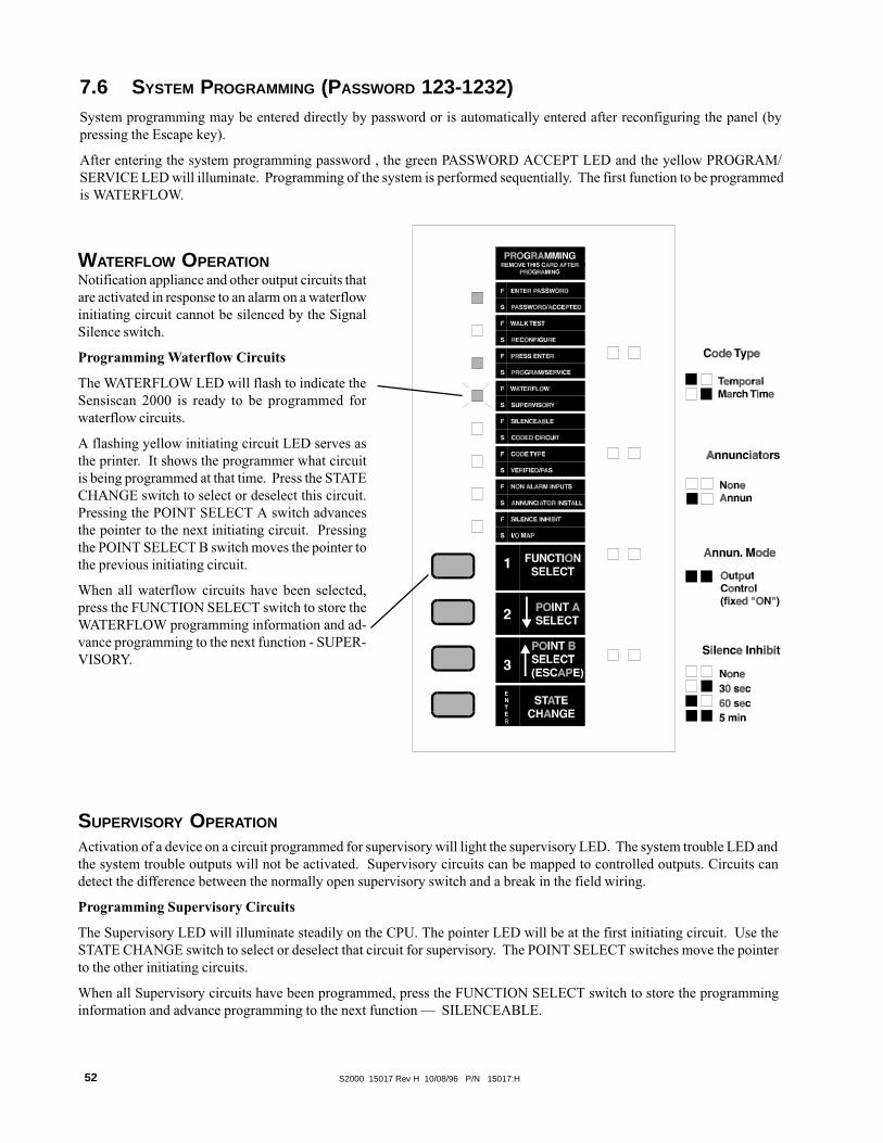
S2000 15017 Rev H 10/08/96 P/N 15017:H52
7.6 SYSTEM PROGRAMMING (PASSWORD 123-1232)System programming may be entered directly by password or is automatically entered after reconfiguring the panel (bypressing the Escape key).
After entering the system programming password , the green PASSWORD ACCEPT LED and the yellow PROGRAM/SERVICE LED will illuminate. Programming of the system is performed sequentially. The first function to be programmedis WATERFLOW.
Activation of a device on a circuit programmed for supervisory will light the supervisory LED. The system trouble LED andthe system trouble outputs will not be activated. Supervisory circuits can be mapped to controlled outputs. Circuits candetect the difference between the normally open supervisory switch and a break in the field wiring.
Programming Supervisory Circuits
The Supervisory LED will illuminate steadily on the CPU. The pointer LED will be at the first initiating circuit. Use theSTATE CHANGE switch to select or deselect that circuit for supervisory. The POINT SELECT switches move the pointerto the other initiating circuits.
When all Supervisory circuits have been programmed, press the FUNCTION SELECT switch to store the programminginformation and advance programming to the next function � SILENCEABLE.
WATERFLOW OPERATIONNotification appliance and other output circuits thatare activated in response to an alarm on a waterflowinitiating circuit cannot be silenced by the SignalSilence switch.
Programming Waterflow Circuits
The WATERFLOW LED will flash to indicate theSensiscan 2000 is ready to be programmed forwaterflow circuits.
A flashing yellow initiating circuit LED serves asthe printer. It shows the programmer what circuitis being programmed at that time. Press the STATECHANGE switch to select or deselect this circuit.Pressing the POINT SELECT A switch advancesthe pointer to the next initiating circuit. Pressingthe POINT SELECT B switch moves the pointer tothe previous initiating circuit.
When all waterflow circuits have been selected,press the FUNCTION SELECT switch to store theWATERFLOW programming information and ad-vance programming to the next function - SUPER-VISORY.
SUPERVISORY OPERATION

S2000 15017 Rev H 10/08/96 P/N 15017:H 53
SILENCEABLE OPERATION
Silenceable circuits are controlled output circuits that, when activated, can be silenced by pressing the signal silence key onthe CPU. Do Not program the Remote Signalling / Municipal Tie output for silenceable operation.
Programming Silenceable Circuits
The SILENCEABLE LED will flash on the CPU. The pointer is represented by a flashing yellow LED on the first outputcircuit. Use the STATE CHANGE switch to select or deselect the circuit for silenceable operation. The green LED willilluminate when the circuit has been selected as silenceable. Use the POINT SELECT switches to move the pointer to theother output circuits.
When all silenceable circuits have been programmed, press the FUNCTION SELECT switch to store the programminginformation and advance programming to the next function � CODED CIRCUITS.
CODED CIRCUIT OPERATION
Selecting controlled outputs for coded operation enables those outputs to pulse a selected code chosen later in the program-ming process (see code type). Outputs that are not selected for coded operation will turn on steady.
Programming Coded Circuits
The CODED CIRCUIT LED will illuminate steadily on the CPU. The pointer will be at the first output circuit. Use theSTATE CHANGE switch to select or deselect the circuit for coded operation. Use the POINT SELECT switches to movethe pointer to the other output circuits.
When all coded circuits have been selected, press the FUNCTION SELECT switch to store the programming informationand advance programming to the next function � CODE TYPE.
CODE TYPE SELECTION
Allows for the selection of March Time Code (110 beats per minute) or Temporal (3-3-3) coding for circuits programmed ascoded in the previous step. Code type selection is on a system basis, therefore all coded circuits will sound the same code.Circuits that were not selected as coded are unaffected by Code Type selection.
Special Requirements apply to codes and code type selection when the system employs a TC-2F or TC-4F module. See theTC-2F Manual and the TC-4F Manual for more information
Programming Code Type
The CODE TYPE LED flashes. Use the STATE CHANGE switch to chose between the two codes:
Green LED for notification appliance circuit 1 on-TemporalYellow LED for notification appliance circuit 1 on-March Time
When code type is programmed, press the FUNCTION SELECT switch to store the programming information and advancethe programming to the next function � VERIFIED ZONES.
Verified / PASVERIFIED/PASAlarm Verification increases the time required to initiate an alarm from two wire smoke detectors. When the system detectsan alarm on an initiating circuit programmed for verification, it will automatically reset the power to that circuit. Power isthen reapplied, beginning a verification period. Any alarm detected during this period will initiate an immediate systemalarm.
Verification should only be used on circuits where false alarm rate cannot be reduced to an acceptable level by other means.Only alarm signals from two-wire smoke detectors can be verified since four-wire smoke detectors are not reset duringverification. Both two-wire smoke detectors and normally-open shorting-type initiating devices may be connected to thesame circuit, although verification will not affect the contact type devices.
Code TypeTemporalMarch Time

S2000 15017 Rev H 10/08/96 P/N 15017:H54
� Building HVAC and energy management sensors such as thermostats or timers could be connected to Non-Alarmpoints and used to open/close ventilation dampers connected to CR-4F relays. In the event of a fire situation, thecontrol panel could force the dampers in one position or the other, and subsequent non alarm state changes wouldbe ignored.
� A manual drill switch could be connected to an IZ point and used to manually test the alarm system withoutcausing a System Alarm or activating a Remote Station.
� Door locks connected to CR-4F/CRE-4F modules could be unlocked when a fire is detected by the Sensiscan 2000.A Non-Alarm point could be used to manually unlock/lock the doors in non-fire situations.
Programming Non-Alarm Inputs
The NON ALARM INPUTS LED will flash. The pointer will be at the first initiating circuit. Use the STATE CHANGEswitch to select or deselect the circuit as a Non Alarm Input. The left-hand LED (red) on each point will illuminate whenthe circuit is selected, and will extinguish when the circuit has been deselected. Use the POINT SELECT switches to movethe pointer to the other initiating circuits. Press the FUNCTION SELECT switch to store this programming and proceed toprogramming the next function � ANNUNCIATOR INSTALLATION.
Positive Alarm Sequence (PAS)
PAS adds a 15 second, post-alarm delay to signal activation. Pressing the ACKNOWLEDGE or SILENCE key before 15seconds has expired will change the timer to its full value (1, 2, OR 3 MINUTES) programmed.
For proper operation of PAS, the following conditions must be met:
1) The control panel must be located so that an alarm signal can be acknowledged by trained personnelwithin 15 seconds.
2) The system must be equipped with a presignal bypass switch.
3) The system must be configured so that activation of a second automatic fire detector bypasses presignaland immediately activates alarm signals. To accomplish this, the installer must install one smoke detector perconventional initiating device.
4) Zones selected for PAS operation shall contain smoke detectors only. These zones may not contain otherinitiating devices such as manual stations, heat detectors, waterflow indicators, etc.
A fire alarm system that fails to meet the above requirements for PAS service will be classified as a presignal systemonly.
Programming Verified or PAS Zones
The VERIFIED / PAS LED will illuminate steady. The pointer will be at the first initiating circuit. Use the STATECHANGE switch to select or deselect the circuit for verification. Use the POINT SELECT switches to move the pointerto the other initiating circuits.
When all VERIFIED / PAS ZONES are programmed press the FUNCTION SELECT switch to store programing infor-mation and advance programming to the next function � NON ALARM INPUTS.
NON ALARM INPUTS
A non-alarm input is an initiating circuit that, upon activation, will not light the System Alarm LED or cause the piezo tosound, will not latch, will self-restore and can be mapped to activate output circuits. Note: If the system is in alarm, orenters an alarm condition, non-alarm inputs WILL latch. When a short circuit occurs on a non-alarm circuit, the IZ redLED is turned on, but the System Alarm LED and the piezo sounder are not activated. Non-alarm points have a lowerpriority compared to regular IZ alarm zones. Non-alarm circuits are "tracking" (non-latching) in that they turn on whenthe circuit is shorted and turn off when the circuit returns to normal (unless the system is in alarm). Non-alarm circuits usethe I/O map capability of the control panel and the mapped controls simply turn on/off as the non-alarm point turns on/off.Non-alarm circuits are supervised for opens.
Applications
Non-Alarm circuits are used to monitor devices that are not fire initiating sensors. Examples of these applications are:

S2000 15017 Rev H 10/08/96 P/N 15017:H 55
ANNUNCIATOR INSTALLATION
Annunciator installation programming allows the programmer to tell the panel if a serial annunciator has been installed.
Note
After the system has been programmed, the Programming Keymust be removed to transfer the programming informationfrom temporary memory storage to nonvolatile memory.
Programming Annunciator Installation
The ANNUNCIATOR INSTALL LED will illuminate steadily. An illuminated green LED for notifica-tion appliance circuit #2 represents an installed annunciator. Use the STATE CHANGE switch toselect or deselect annunciator installation. After programming annunciator installation, press the FUNC-TION SELECT key to store the programming information and advance programming to the next func-tion.
Annunciators
None
Annun
SILENCE INHIBIT
The SILENCE INHIBIT function prevents the operation of the Signal Silence switch for 30 seconds,60 seconds or 5 minutes after the output circuits have been activated.
Programming Silence Inhibit
The SILENCE INHIBIT LED will flash. Use the STATE CHANGE switch to select SilenceInhibit time as represented by the Alarm Relay LEDs.
After programming Silence Inhibit press the FUNCTION SELECT switch to store this informa-tion and select the next function � I/O Map.
INPUT/OUTPUT MAPThe I/O map is the assignment of output circuits to be activated by par-ticular initiating circuits. Unmapped initiating circuits will not generate asystem alarm. Unmapped controlled outputs will not operate.
Silence Inhibit
None
30 sec
60 sec
5 min
Programming the I/O MAP
The I/O Map LED will illuminate steadily. The red LED pointer willilluminate steadily on the selected initiating circuit. A yellow flashingLED points to an output circuit. Pressing the STATE CHANGE switchwill select or deselect the output circuit to be activated by the initiatingcircuit. Use the POINT B SELECT to scroll through each of the outputcircuits and the STATE CHANGE switch to select/deselect the outputs(after scrolling through all of the output circuits it will cycle back to thefirst).
After each of the output circuits has been selected/deselected, press thePOINT A SELECT switch to move the red pointer to the next initiatingcircuit. Continue mapping outputs for each initiating circuit.
After programming the I/O map, press the FUNCTION SELECT key tostore I/O map programmed. If you do not press the FUNCTION SE-LECT switch after programming the I/O Map, the I/O map will notbe saved. Yellow LEDs on initiating circuits show unmapped circuits.Press ESCAPE switch to return to I/O mapping, or ENTER switch toreturn to Waterflow. Remove the Programming Key to exit program-ming mode.

S2000 15017 Rev H 10/08/96 P/N 15017:H56
The following features are available in CPU EPROM U4 software numbered 73265 (or greater).
The AUTO SILENCE feature will automatically turn off all silenceable circuits after a pre-programmed delay. The delaytimer starts after a system alarm. Any subsequent alarms which occur before the auto silence activates will restart the delaycountdown at zero.
The PRESIGNAL DELAY delays the activation of all silenceable circuits mapped to a zone in alarm for a pre-programmedlength of time. A subsequent alarm aborts the delay and re-maps all alarm points. Pressing the SIGNAL SILENCE switchbefore the delay time has expired aborts the delayed activation of the silenceable circuits. Note: When Pre-Signal Delayhas been selected, at least one notification appliance circuit must be programmed as non-silenceable. This willensure that at least one notification circuit will sound immediately after initiation of an alarm condition.
The POSITIVE ALARM SEQUENCE (PAS) function adds a timer. After a first alarm, the timer is set for 15 seconds. Ifnothing happens in that 15 seconds, all signals are activated. If an ACKNOWLEDGE or SILENCE key (including annuncia-tor keys) is pressed before 15 seconds, the timer changes to its full value (1, 2, or 3 minutes).
Note: When Pre-Signal has been selected, at least one notification appliance circuit must be programmed as non-silenceable.This will ensure that at least one notification Circuit will sound immediately after initiation of an alarm condition.
NFPA 72-1993 requires the installation of a Day/Night/Weekend switch that can override PAS operation. This can beaccomplished by using a normally open switch to close an IZ-8F that has been programmed for NON-ALARM and SUPER-VISORY operation. Note that the zone cannot have a notification appliance circuit mapped to it.
The switch totally inhibits all presignal function. On entering presignal mode, the CPU checks zone 1 in module 1. If this isan IZ-8F zone set for NON-ALARM and SUPERVISORY, and it is active (switch is on), all presignal and PAS operationwill be ignored.
AC LOSS REPORT DELAY When a Digital Alarm Communicator Transmitter (DACT) is used, the reporting of an ACLoss condition must be delayed. With software P/N 73452 (or higher), this function can be selected under extended pro-gramming features. When selected, the CPU's trouble contacts will not be activated for loss of AC power until approxi-mately 8 hours after loss of power occurs.
The CALIFORNIA CODE mode adds a ten second timer to the two notification circuits on the CPU. When an alarmoccurs, the timer is started. At the end of the ten second period, all silenceable circuits are shut off for five seconds. NOTE:The circuits on the CPU and the circuits on the IC-4F are controlled by different microprocessors and may not be insynchronization with each other. At the end of the five seconds, the circuits are turned on again for 10 seconds. This cyclerepeats indefinitely.
In the event of an acknowledged alarm, the REMINDER mode pulses the piezo every 15 seconds. If an acknowledgedtrouble exists, but not an alarm, the piezo will beep every two minutes.
EXTENDED PROGRAMMING FEATURES (PASSWORD 123-3211)

S2000 15017 Rev H 10/08/96 P/N 15017:H 57
To program the features of AUTO SI-LENCE, PRESIGNAL DELAY, andCALIFORNIA CODE, key in the pass-word 123-3211 and push ENTER.
In addition to PASSWORD ACCEPTEDand PROGRAM/SERVICE LEDs, theNON-ALARM LED will flash on theCPU.
Press the ENTER switch to scroll throughthe options for AUTO SILENCE until theLEDs reflect the desired choice.
Press the FUNCTION SELECT switchto store the option setting in memory andadvance to the next point to be pro-grammed. Again, press the ENTERswitch until the LEDs reflect the desiredchoice, followed by the FUNCTION SE-LECT switch to store the data.
To exit extended programming at anytime, remove the programming key. The123-3211 password does not allow accessto any other program features and doesnot cause the system to reconfigure.
CPU-2000
*Applies only to zones selected as "Verified/PAS."

S2000 15017 Rev H 10/08/96 P/N 15017:H58
Note: The CPU produces a pulsed tone for troubles, disabled outputs,and supervisory conditions. A continuous tone is generated for alarms.
SECTION EIGHT: OPERATION
CPU LED Indicators
A green LED that indicates the presence of normal AC power. This LED is turned offwhen the AC line voltage falls below normal.
A red LED that indicates an alarm condition. This LED initially flashes during alarm(the CPU will also sound a continuous audible tone). Silencing or acknowledging thealarm(s) turns the audible tone off and causes the LED to illuminate steadily. Subsequentalarms will resound the audible tone and flash their LEDs. Alarm signals latch until thecontrol panel is reset.
A yellow LED that indicates activation of a circuit programmed to monitor supervisorydevices.
Indicates the presence of a trouble condition in the system.
Indicates the failure of a module in the control unit or an annunciator failure.
Indicates 1) that a power supply is not functioning correctly, 2) AC line voltage is belownormal, 3) improper battery voltage, or 4) that a ground fault exists. Additional informa-tion is displayed on internal LEDs located on power supply assemblies.
Indicates that an output circuit is silenced. Indication will remain until the reset switch isdepressed.
Indicates that a circuit(s) within the system has been manually disabled.
CPU Control Switches
Depressing ACKNOWLEDGE turns the audible tone off and switches LED operationfrom flashing to steady. A subsequent trouble or alarm will resound the audible tone andflash appropriate LEDs.
Returns all silenceable outputs, which were automatically activated by the alarm condi-tion, to their non-alarm state. A subsequent alarm can reactivate alarm outputs.
The System Reset Switch will reset the system provided that the alarm condition is clear.Holding this switch depressed will sequentially light (lamp test) all LEDs.
The Lamp Test Switch illuminates all the LEDs in the system for as long as the switch isheld down. This switch can also be used to disable or enable individual circuits.

S2000 15017 Rev H 10/08/96 P/N 15017:H 59
Notification Appliance Circuit #1
Notification Appliance Circuit #2
Municipal Box/Remote Signaling Tie
Form-C Alarm Relay
Green LEDs:
Each output has a green LED thatindicates activation of that circuit.
Yellow LEDs:
Each output circuit has a yellow LED that indi-cates trouble conditions or disabled outputs. New
troubles are indicated by a flashing LED.
8.1 CPU-2000 CIRCUITS
The CPU Module contains: 1) Two supervised notification appliance circuits that can be used to control evacuation signalingdevices such as bells, chimes, horns, and strobes. 2) An alarm relay that can control external devices such as elevators, anddoors. 3) A Remote Signaling/Municipal Tie output for connection to a municipal fire department, central station, or aremote monitoring station.

S2000 15017 Rev H 10/08/96 P/N 15017:H60
IZ Series
Initiating Zone Module
Each Initiating Zone Module will moni-tor up to eight initiating zones (groups)of initiating devices (smoke detectors,pull stations, heat detectors) for alarmsignals. It also checks the integrity of thebuilding wiring between the module andthe initiating devices. The IZ-4F and IZ-8F modules convey the status of the ini-tiating zones and their wiring to the CPUmodule and at the direction of the CPUwill light the appropriate LEDs to dis-play alarm and trouble conditions (bro-ken wire, inactive circuit, etc.).
The red LEDs indicate alarm conditions.New alarms are indicated by a flashingLED and a steady audible tone. Silenc-ing an alarm turns the audible tone offand causes the LED to illuminate steadi-ly.
The yellow LEDs indicate an initiatingzone trouble or a disabled zone. Newtroubles are indicated by a flashing LEDand a pulsed audible tone. Silencing atrouble turns the audible tone off andswitches LED operation from flashingto steady. A subsequent trouble from adifferent initiating zone will resound theaudible tone and flash its LED. Troublesignals will self-restore as soon as thetrouble conditions are corrected.
IC-4F
Notification Circuit Module
Each Indicating Circuit Module willcontrol and monitor up to eight notifi-cation appliance circuits (with an ICE-4F expander installed) of evacuationsignaling devices, such as bells, chimes,horns, and lights. The IC-4F moduleconveys the status of the notificationappliance circuits and their wiring to theCPU module and at the direction of theCPU will light the appropriate LEDs todisplay activation and trouble condi-tions (broken wire, inactive circuit). Thenotification appliance circuits activateautomatically during an alarm conditionaccording to a program instructionsstored in CPU nonvolatile memory.
The green LEDs indicate an activatednotification appliance output.
The yellow LEDs indicate a notifica-tion circuit trouble or a disabled circuit.New troubles are indicated by a flash-ing LED and a pulsed audible tone. Si-lencing a trouble turns the audible toneoff and causes the LED to illuminatesteadily. A subsequent trouble from adifferent circuit will resound the audibletone and flash the associated troubleLED. Trouble signals will self-restoreas soon as the trouble condition hasbeen corrected.
This module is programmable for Cali-fornia Code. Cutting D35 programs thiscard for California Code.
CR-4F
Control Relay Modules
Each Control Relay Module controlsup to eight relays (with a CRE-4F ex-pander installed) which can be con-nected to control external devices in-cluding elevators, doors, and air han-dling equipment. These relays will beactivated automatically during analarm condition according to programinstructions stored in CPU module'smemory.
The green LEDs indicate that the as-sociated control relay has been acti-vated.
The yellow LEDs indicate that the as-sociated control relay output has beendisabled.

S2000 15017 Rev H 10/08/96 P/N 15017:H 61
ACKNOWLEDGESILENCE TONE
SIGNALSILENCE
SYSTEMRESET
LAMP TESTDISABLE/ENABLE
1
2
3
Caution: Disabling a circuit will reduce or eliminate fire protection.
1) Press the LAMP TEST switch and hold it in throughoutthe remainder of this procedure.
2) Press 1, 2, 3. If any circuits have been previouslydisabled, they will be indicated by illumination of theirleft-hand LED (red for initiating circuits, green for allothers).
The position of the circuit pointer is indicated by theflashing yellow LED.
To move forward in the circuit map, press Switch 3(SYSTEM RESET). To move backward in thecircuit map, press Switch 2 (SIGNAL SILENCE).
3) Move forward or reverse until the pointer stops at thecircuit to be disabled.
4) Press Switch 1 (ACKNOWLEDGE) to turn on the left-hand LED on the circuit to be disabled. When thisLED is on, the circuit has been disabled.
A circuit can be re-enabled by pressing Switch 1 untilthe left-hand LED goes out.
5) Repeat steps 3 and 4 until all disabling/enabling hasbeen accomplished.
6) Release the LAMP TEST switch to exit Disable/Enablemode. The control panel will return to operation withthe selected circuits disabled.
8.2 DISABLING /ENABLING CIRCUITS
Note: The disable feature will not work if the CPU Write Inhibit Switch has been set (refer to page 51 for details).
For servicing of the Sensiscan 2000, input or output circuits can be disabled. To disable a circuit, a 1-2-3 key sequence mustbe entered and the operator must advance to the circuit to be disabled. **This does not work in program mode.

S2000 15017 Rev H 10/08/96 P/N 15017:H62
SECTION NINE: SENSISCAN 2000 TESTING
9.1 ACCEPTANCE TEST
Upon completion of the original installation and following subsequent modifications, a complete operational test should beconducted on the entire installation for the purpose of verification of compliance with the applicable NFPA standards.Testing should be conducted by a factory-trained distributor in the presence of a representative of the Authority HavingJurisdiction and the Owner's Representative. Follow procedures contained in NFPA Standard 72-1993, Chapter 7, "Inspec-tion, Testing and Maintenance."
9.2 PERIODIC TESTING AND SERVICE
Periodic testing and servicing of the Sensiscan 2000, all initiating devices and notification appliances, and any other associ-ated equipment is essential to insure proper and reliable operation. Testing and servicing should be in accordance with theschedules and procedures outlined in: 1) NFPA 72-1993, Chapter 7, "Inspection, Testing and Maintenance" and 2) theservice manuals and instructions for the peripheral devices contained in your system. Correct any trouble condition ormalfunction immediately.
9.3 OPERATIONAL CHECKS
Between formal periodic testing and servicing intervals, the following operation checks should be performed monthly ormore frequently when required by the Authority Having Jurisdiction.
1) Check that the green "AC POWER" LED is illuminated.
2) Check that all yellow LEDs are off.
3) Holding "SYSTEM RESET" depressed should sequentially light all system LEDs.
4) Before proceeding, a) notify fire department and/or central alarm receiving station if alarm conditions are transmit-ted; b) notify facility personnel of test so that alarm sounding devices are ignored during test period. Whennecessary, activation of alarm notification appliances can be prevented by disabling those circuits.
5) Activate an initiating device circuit via an alarm initiating device and check that all active notification appliancesfunction. Reset the alarm initiating device, the control panel, and any other associated equipment.
6) Repeat Step 5 for each initiating device circuit.
7) Remove AC power, activate an initiating device circuit via an alarm initiating device and check that active notifica-tion appliances sound, and alarm indicators illuminate. Measure the battery voltage while notification appliancesare activated. Replace any battery with a terminal voltage less than 21.6 volts. Replacement batteries may beobtained from Fire�Lite. Minimal replacement battery capacity is indicated on the control panel marking label.Reapply AC Power. Note: This test requires fully charged batteries, if batteries are new or discharged due to arecent power outage, allow the control panel to charge batteries for 48 hours before testing.
8) Check that all yellow LEDs are off and that the green "AC POWER" LED is illuminated.
9) Notify fire, central station and/or building personnel that test is complete.

S2000 15017 Rev H 10/08/96 P/N 15017:H 63
9.4 BATTERY CHECKS AND MAINTENANCE
Maintenance-free sealed lead-acid batteries used in Sensiscan 2000 do not require the addition of water or electrolyte. Theyare charged and are maintained in a fully charged state by the main power supply's float charger during normal systemoperation. A discharged battery will charge at 1.5 amps (typically) and obtain its float voltage of 27.6 volts within 48 hours.
Replace any battery that is leaking or damaged. Replacement batteries may be obtained from Fire-Lite. Minimal replace-ment battery capacity is indicated on the control panel marking label. To check battery and system, Refer to Section "Opera-tional Checks" above.
CAUTION!
Batteries contain Sulfuric Acid which can cause severe burns to the skin and eyes anddamage to fabrics. In the event a battery leaks and contact is made with the Sulfuric Acid,immediately flush skin and/or eyes with water for at least 15 minutes. For eyes, seek imme-diate medical attention. A good neutralizing solution for Sulfuric Acid is water and house-hold baking soda. Care should be taken to insure proper handling of the battery to prevent
short-circuiting. Accidental shorting of the leads from uninsulated work benches, tools,bracelets, rings, and coins should be avoided. Shorting the battery leads can damage the
battery, equipment, and could cause injury to personnel.
9.5 WALK TESTING THE SENSISCAN 2000In order to execute Walk Test from the Sensiscan 2000, the CPU Programming Key must be inserted.
Enter the Walk Test password (123-1233) then press ENTER. Depress the Enter Switch again. The PASSWORD AC-CEPTED LED will light and the WALK TEST LED will flash. Activate an initiating device and all output circuits that areprogrammed as silenceable will activate for approximately four seconds. If an initiating device circuit is activated morethan once, the outputs will activate for approximately one second. Once an initiating circuit has been activated, its red LEDwill flash. All of the red LEDs on the initiating circuit modules will illuminate. The green LEDs on all notification appliancecircuits that are silenceable will illuminate.
Testing Initiating Circuits for Trouble
Inducing a trouble into an initiating circuit will activate all output circuits that are programmed as silenceable. The outputswill remain activated until the trouble is cleared. After a circuit is tested for trouble, the yellow LED for that circuit willflash.
Testing Notification Appliance Circuits for Trouble
Inducing a trouble into a notification circuit will activate the particular circuit and pulse the circuit at one second on/off rateuntil the trouble is cleared.
Exiting Walk Test
To exit Walk Test, remove the programming key.
NOTE: Four-wire smoke detectors cannot be tested under Walk Test.

S2000 15017 Rev H 10/08/96 P/N 15017:H64
APPENDIX A: SUPPLY CALCULATIONS
Table A-1: AC Fire Alarm Circuit
Use Table A-1 to determine the total amount of current, in AC amps, that the AC service must be capable of supplying to thesystem.
A.2 THE MAIN POWER SUPPLY
The main power supply must be capable of powering all internal system devices (and several external types of devices)continuously during non-fire alarm conditions. Use Table A-2A to determine the Non-Fire Alarm Load on the main powersupply regulator when a primary power is applied. A finite amount of additional current must be provided by the powersupply during a fire alarm condition. Use Table A-2B to determine the additional current needed during fire alarms. Therequirements for non-fire alarm and fire alarm current loads cannot exceed the capabilities of the power supply in eithercase.
The MPS-24AF provides up to 3.0 amps of regulated current for operating the system in standby (non-fire alarm) and up to6.0 amps during fire alarms. The MPS-24AF contains battery charging circuitry and a 1-amp regulated output for poweringfour-wire smoke detectors. The MPS-24BF provides 750 mA of regulated power for system modules and 2.0 amps forNotification Appliances.
A.1 THE FIRE ALARM CIRCUIT
The control panel requires connection to a separate dedicated AC fire alarm circuit, which must be labeled "FIRE ALARM."This circuit must connect to the line side of the main power feed of the protected premises. No other equipment may bepowered from the fire alarm circuit. The AC circuit wire run must run continuously, without any disconnect devices, fromthe power source to the fire alarm control panel. Overcurrent protection for this circuit must comply with Article 760 of theNational Electrical Code as well as local codes. Use #12 AWG wire with 600V insulation for this circuit.
eciveD seciveDfo#ylpitluM
yB
tnerruCni
spmAtnerruClatoT
EFA42-SPM/FA42-SPMro
EFB42-SPM/FB42-SPM1 X 9.0/8.1 9.0/8.1
EF42-SPVA/F42-SPVA ][ X 5.0/0.1
etomeRE42-54R/42-54RregrahC
1 X 5.0/0.1
=*daoLmralAeriFyradnoceSrofnmuloCmuS spma
Note
Devices rated for 220/240 VAC operation ("E" products) will draw one halfof the current of devices rated for 120 VAC operation.

S2000 15017 Rev H 10/08/96 P/N 15017:H 65
SENSISCAN 2000 SYSTEM CURRENT DRAW CALCULATION TABLE (TABLE A-2A)Note: The Primary Power Source Non-Alarm Current and Alarm Current columns of this table are not battery calculations.They are simply current calculations to confirm that the main power supply can supply enough current to support the systemduring Primary Non-Alarm and Fire Alarm conditions.
Note: Throughout these current calculation tables, the word "primary" refers to the FACP's primary source of power, i.e.AC power. The word "secondary" refers to the FACP's backup batteries (or any other 24 VDC uninterruptable, regulatedpower supply listed for Fire Protective Signaling and connected in place of the batteries).
Part One - Non-Alarm Current (Primary Power Source): This column of Table A-2A allows the user to calculate thecurrent that will be drawn from the main power supply during a non-alarm condition, with AC power applied. This currentdraw cannot exceed 750 mA on the MPS-24BF or 3.0 amps on the MPS-24AF. This column does not account for currentdrawn from TB2-3 and TB2-4 in non-alarm conditions on the MPS-24BF which is limited to 0.800 amps, exclusive of the0.750 amps limit on the non-alarm current load. Current drawn from TB2-1 and TB2-2 cannot exceed 0.200 amps at anytime on the MPS-24BF.
Part Two - Fire Alarm Current (Primary AC Power): The second column of Table A-2A allows the system designer todetermine the additional current load that must be supported by the main power supply during a fire alarm condition withprimary power applied. This current drawn during a fire alarm cannot exceed 0.750 amps on the MPS-24BF. This columndoes not account for current draw from TB2-3 and TB2-4 in fire alarm which is limited to 2.0 amps exclusive of the 0.750amps fire alarm load. The fire alarm load cannot exceed 6 amps for the MPS-24AF and 2.3 amps for the MPS-24BF.
Note: Typically, a system should be designed around the capacity to activate all output circuits and relays, andsupport fire alarms on no less than 10% of initiating device circuits (subject to the requirements of the LocalAuthority Having Jurisdiction (LAHJ).
Concerning four-wire detectors: In Table A-2A, the current to be entered for four-wire smoke detectors is themanufacturer's rated fire alarm current minus the manufacturer's rated non-fire alarm current.
Concerning notification appliances: The main power supply provides a regulated supply for notification appliancecircuits, permitting the use of any 24 VDC notification appliances UL listed for Fire Alarm Systems. Enter intoTable A-2A the respective current draws of notification appliances and other external devices to be powered by themain power supply during a fire alarm.
Part Three - Non-Fire Alarm Current (Secondary battery power): The last column of Table A-2A allows the systemdesigner to calculate the secondary non-fire alarm current. This is the current that will be drawn from the main power supplyin a non-fire alarm condition during AC power loss. This figure is required to complete the standby battery calculations.After adding up all the individual current draws, the total figure is then transferred to Table A-2C.

S2000 15017 Rev H 10/08/96 P/N 15017:H66
Table A-2A: Sensiscan 2000 System Current Draw Calculations
Notes:1) The total regulated load current supplied to external circuits cannot exceed 3.0 amps (MPS-24AF) or 0.200 amps (MPS-24BF).2) MPS-24BF: Enter only notification appliance draw from TC-2F/TC-4F circuits. MPS-24AF: Enter total notification appliance draw for
entire system. Do not include power from AVPS-24F supplies!3) The Alarm Load cannot exceed 6 amps for the MPS-24AF. For the MPS-24BF, the alarm load limit is 750 mA for both internal needs and
power drawn from TB2-1 and TB2-2. The alarm load limit is 2.0 amps from TB2-3 and TB2-4.
yrogetaC
ecruoSrewoPyramirP ecruoSrewoPyradnoceS
)spma(tnerruCmralA-noN )spma(tnerruCmralA )spma(tnerruCmralA-noN
ytQ =]wardtnerruc[X latot ytQtnerruc[X
=]wardlatot ytQ =]wardtnerruc[X latot
UPC 1 =]130.0[x 130.0 1 =]322.0[x 322.0 1 =]130.0[x 130.0
EFA42-SPM/FA42-SPMEFB42-SPM/FB42-SPM
1=]460.0[x=]260.0[x
1=]460.0[x=]260.0[x
1=]401.0[x=]220.0[x
EF42-SPVA/F42-SPVA ][ =]900.0[x ][ =]900.0[x ][ =]900.0[x
F8-ZIFA-EZI
F4-RC,F4-CIF4-ECIF4-ERC
4-CT,2-CT
][][][][
][
=]740.0[x=]400.0[x=]700.0[x=]100.0[x
elbacilppaton=]700.0[x
][][][][][][
=]740.0[x=]300.0[x=]270.0[x=]560.0[x=]560.0[x=]270.0[x
][][][][
][
=]740.0[x=]400.0[x=]700.0[x=]100.0[x
elbacilppaton=]700.0[x
FA23-MFA,FTA61-MFAFA23-MCA,FTA61-MCA
FA61-MFAotrefer(XA23-MFA,XTA61-MFA
)09351.coD
][][][][
=]040.0[x=]040.0[x=]520.0[x=][x
][][][][
=]650.0[x=]650.0[x=]560.0[x=][x
][][][][
=]040.0[x=]040.0[x=]520.0[x=][x
refer(srotceteDekomSeriW-2ytilibitapmoCeciveDehtot
)swardtnerrucroftnemucoD
][][][][
=][x=][x=][x=][x
][][][][
=][x=][x=][x=][x
][][][][
=][x=][x=][x=][x
senoz03ot1senoz04ot13senoz94ot14senoz65ot05
ELBACILPPATON
][][][][
=]021.0[x=]061.0[x=]002.0[x=]042.0[x
ELBACILPPATON
rotacinummoCA119rotacinummoCTCADU
][][
=]030.0[x=]040.0[x
][][
=]761.0[x=]001.0[x
][][
=]030.0[x=]040.0[x
rewopgniwardsecivedrehtOgnidulcxeylppusrewopehtmorf
rewoPecnailppAnoitacifitoN)3dna1setonees(
][][][][
=][x=][x=][x=][x
][][][][
=][x=][x=][x=][x
][][][][
=][x=][x=][x=][x
syaleRnoisivrepuSrewoP)1etonees(
][][
=][x=][x
][][
=][x=][x
][][
=][x=][x
morfwarDeciveDgnisaeleRstiucricF4-CT/F2-CT)2dna1setonees(
ELBACILPPATON ][ =][x ELBACILPPATON
stiucriCnoitatSetomeR)1etonees(
][ =]810.0[x ][ =]810.0[x ][ =]810.0[x
srotceteDekomSeriW-4)1etonees(
][][
=][x=][x
][][
=][x=][x
][][
=][x=][x
slatotrofnmulochcaemuS :latotmralaerif-non,yramirP :latotmrala,yramirPmralaerif-non,yradnoceS
:latot

S2000 15017 Rev H 10/08/96 P/N 15017:H 67
Maximum Secondary Power Fire Alarm Current Draw
Use Table A-2B to determine the maximum current requirements of secondary power source during fire alarm conditions.The total obtained in Table A-2B is the amount of current that the batteries must be capable of supplying. This figure willbe used in Table A-2C to determine the size of the batteries needed to support five minutes of fire alarm operation.
Table A-2B assumes that while in a fire alarm condition, the batteries must feed the main power supply and any additionalsupplies (AVPS-24F/AVPS-24FE) with the maximum rated power each supply can provide. Note: Due to the maximumrating of 9 amps imposed when using PS-12250 batteries, it may be necessary to calculate the exact requirements of thesecondary supply. In that case, add the Secondary Non-Fire Alarm Load obtained in Table A-2A to the total fire alarmcurrent draw of all Notification Appliances in the system and substitute that figure in Table A-2B for the main power supplyand any additional supplies.
Notes:1. NFPA 72-1993 Local, Central Station, and Proprietary Fire Alarm Systems require 24 hours of standby power followed by five
minutes in alarm. NFPA 72-1993 Auxiliary and Remote Station Fire Alarm Systems require 60 hours of standby power followed byfive minutes in alarm. Batteries installed in a system powered by a generator need to provide at least four hours of standby power.
2. If the total exceeds 55AH (17AH on the MPS-24BF), a UL-listed Uninterruptable Power Supply (UPS) with sufficient capacity isneeded. If the system does not have battery backup, a UPS must be installed in the same room as the FACP.
Table A-2C: Secondary Power Standby and Fire Alarm Load
Table A-2B: Maximum Secondary Power Fire Alarm Current Draw
eciveDepyT
rebmuNledoMfo#
seciveDtnerruC)spma(
latoTtnerruC
rewoP:seilppuS
EFA42-SPM/FA42-SPMro
EFB42-SPM/FB42-SPM1 X
0.6ro39.2
=
EF42-SPVA/F42-SPVA[]
X 0.3 =
daoLmralAyradnoceSrofnmuloCmuS = spma
eriF-noNyradnoceSdrihtmorf(daoLmralA)A2-AelbaT,nmuloc
X
-noNyradnoceSderiuqeRemiTybdnatSmralAeriF
)sruoh06ro42(=
mralAeriF-noNyradnoceS
pmAybdnatSsruoH
mralAeriFyradnoceSdaoL
)B2-AelbaTmorf( X
emiTmralAeriFderiuqeR,480.0retne,setunim5roF(
)52.0retne,setunim51rof =
eriFyradnoceSruoHpmAmralA
tnemeriuqeR
sruoHerepmAyradnoceSlatoTrofnmuloCmuS=detaluclac
=2.1XrotcafgnitaredehtybylpitluM
deriuqeRsruoHerepmAyradnoceSlatoT spma

S2000 15017 Rev H 10/08/96 P/N 15017:H68
Calculating battery size needed
Table 8.2E sums the standby and alarm loads toarrive at the battery size, in ampere hours, neededto support the system. Each main power supplyhas a specific range of batteries that can becharged properly. Select batteries that meet orexceed the Total Ampere-Hours calculated andthe are within the acceptable charger range:
Battery Charger Amp-Hour Range:
MPS-24AF (9-55AH)
MPS-24BF (6.5-17AH)
yrettaBeziS
egatloVgnitaR
rebmuNderiuqeR
traPrebmuN
eziStenibaC
HA0.7HA5.9HA21HA71HA52HA55
stlov21stlov6stlov21stlov21stlov21stlov21
owtruof
owtowtowtowt
0721-SP596-SP
02121-SP07121-SP05221-SP00621-SP
F3B-BAC,F3A-BACF3B-BAC,F3A-BACF3B-BAC,F3A-BACF3B-BAC,F3A-BACF3B-BAC,F3A-BACF3B-BAC,F3A-BAC

S2000 15017 Rev H 10/08/96 P/N 15017:H 69
Sensiscan 2000 Programming Log
dnegeL
epyTenoZretteLenOretnE
epyTnoitacifitoN)s(retteLretnE
F eriF- R yaleR-
W wolfretaW- CT lortnoCemiT-
S yrosivrepuS- VA lausiVoiduA-
N mralAnoN-MSR etomeR-
lapicinuM/noitatS
-T eiT
eludoMnoitisoP
tiucriCrebmuN
lebaLtiucriCgnitaitinIenoZepyT
mralAyfireV
stiucriCnoitacifitoNdeppaM
stiucriC0002-UPCnoitsisoPeludoMtuptuOretnE(
)#tiucriC&1DNI 2DNI xoB.M
mralAyaleR

S2000 15017 Rev H 10/08/96 P/N 15017:H70
CAB-A3F
CAB-B3F
Cabinet Module Position Layout
1. Cross out unused rows.
2. Fill module blocks with appropriate model num-ber (IZ-8F, IZE-AF, IZ-4F, IC-4F, ICE-4F, CR-4F,CRE-4F, TC-2F, TC-4F)
eludoMnoitisoP
tiucriCrebmuN
tiucriCnoitacifitoNlebaL
tiucriCepyT
?dedoC ?elbaecneliS
A1 1
A1 1
A1 1 TM/SR
A1 1
0002-UPCA1 B1 C1 D1
0002-UPCA1 B1 C1 D1
A2 B2 C2 D2
sgnitteSediW-metsyS
:epyTedoC q laropmeT q emiThcraM
:tibihnIecneliS q enoN q .ces03 q .nim1 q .nim5
:ecneliSmralA q enoN q .nim5 q .nim01 q nim02
yaleDlangiS-erP q enoN q .nim1 q .nim2 q .nim3
dnegeL
epyTenoZenOretnE
retteL
epyTnoitacifitoN)s(retteLretnE
F eriF- R yaleR-
W wolfretaW- CT lortnoCemiT-
S yrosivrepuS- VA lausiVoiduA-
N mralAnoN-MSR etomeR-
lapicinuM/noitatS
-T eiT

S2000 15017 Rev H 10/08/96 P/N 15017:H 71
Notes

Fire-Lite® warrants its products to be free from defects in materials and workmanshipfor eighteen (18) months from the date of manufacture, under normal use and service.Products are date stamped at time of manufacture. The sole and exclusive obligationof Fire-Lite® is to repair or replace, at its option, free of charge for parts and labor, anypart which is defective in materials or workmanship under normal use and service.For products not under Fire-Lite® manufacturing date-stamp control, the warranty iseighteen (18) months from date of original purchase by Fire-Lite®'s distributor unlessthe installation instructions or catalog sets forth a shorter period, in which case theshorter period shall apply. This warranty is void if the product is altered, repaired orserviced by anyone other than Fire-Lite® or its authorized distributors or if there is afailure to maintain the products and systems in which they operate in a proper andworkable manner. In case of defect, secure a Return Material Authorization form fromour customer service department. Return product, transportation prepaid, to Fire-Lite®, One Fire-Lite Place, Northford, Connecticut 06472-1653.
This writing constitutes the only warranty made by Fire-Lite® with respect to its products.Fire-Lite® does not represent that its products will prevent any loss by fire or otherwise,or that its products will in all cases provide the protection for which they are installedor intended. Buyer acknowledges that Fire-Lite® is not an insurer and assumes norisk for loss or damages or the cost of any inconvenience, transportation, damage,misuse, abuse, accident or similar incident.
Fire-Lite® GIVES NO WARRANTY, EXPRESSED OR IMPLIED, OFMERCHANTABILITY, FITNESS FOR ANY PARTICULAR PURPOSE, OR OTHERWISEWHICH EXTEND BEYOND THE DESCRIPTION ON THE FACE HEREOF. UNDERNO CIRCUMSTANCES SHALL Fire-Lite® BE LIABLE FOR ANY LOSS OF ORDAMAGE TO PROPERTY, DIRECT, INCIDENTAL OR CONSEQUENTIAL, ARISINGOUT OF THE USE OF, OR INABILITY TO USE Fire-Lite® PRODUCTS.FURTHERMORE, Fire-Lite® SHALL NOT BE LIABLE FOR ANY PERSONAL INJURYOR DEATH WHICH MAY ARISE IN THE COURSE OF, OR AS A RESULT OF,PERSONAL, COMMERCIAL OR INDUSTRIAL USE OF ITS PRODUCTS.
This warranty replaces all previous warranties and is the only warranty made by Fire-Lite®. No increase or alteration, written or verbal, of the obligation of this warranty isauthorized.
"Fire-Lite" is a registered trademark.
Limited Warranty
One Fire-Lite Place, Northford, CT 06472Phone: (203) 484-7161FAX: (203) 484-7118
Technical Publishing Document WARFBG-D.P65 11/04/98

Sensiscan 2000 Operating Instructions
NORMAL STANDBY OPERATION : 1) The green AC POWER indicator must be lit, 2) all alarm (red LEDs) and troubleindicators (yellow LEDs) should be off.
ALARM CONDITION: Activation of a compatible detector or any normally open fire alarm initiating device will result in thefollowing action by the System 500 control panel: 1) activate alarm notification, control, and signaling outputs as programmed,2) light the Red SYSTEM ALARM LED and the associated initiating circuit alarm LED(s), and 3) A steady audible tone will sounduntil the alarm is acknowledged or silenced. The controlled outputs will remain activated and the associated alarm LEDs willflash until the alarm has been silenced or acknowledged, or the system has been reset.
If PRESIGNAL DELAY has been pro-grammed, the activation of allsilenceable output circuits will be de-layed by the time marked at right. ForPositive Alarm Sequence (PAS): If theACKNOWLEDGE or SILENCE keysare not pressed within 15 seconds ofinitiation of a first (and only) alarm,output signals will be activated. Other-wise, the programmed PAS 1, 2, orthree-minute time delay will take effect.
❑❑❑❑❑❑❑❑❑❑❑❑❑❑❑❑❑❑❑❑❑❑❑❑❑❑❑❑❑❑❑❑❑❑❑
None selected
1 Minute
2 Minutes
3 Minutes
PAS 1 Minute
PAS 2 Minutes
PAS 3 Minutes
If ALARM SILENCE has been programmed, allsilenceable output circuits will be shut off afterthe time marked at right.
❑❑❑❑❑❑❑❑❑❑❑❑❑❑❑❑❑❑❑❑
None selected
5 Minutes
10 Minutes
20 Minutes
❑❑❑❑❑❑❑❑❑❑❑❑❑❑❑❑❑❑❑❑
None selected
30 Seconds
1 Minute
5 Minutes
If SIGNAL SILENCE INHIBIT hasbeen programmed, Signal Si-lence will not function for the in-hibit time marked at right.
ACKNOWLEDGE (SILENCE TONE): Depressing the ACKNOWLEDGE switch will turn the audible tone off and switchoperation of associated LED(s) from flashing to steady. New alarms and/or troubles will resound the audible tone and flashtheir associated LED(s).
ALARM SILENCING PROCEDURE: Alarm notificationappliance circuits, control relays and signalling circuits thathave been programmed as silenceable may be silenced bydepressing the SIGNAL SILENCE switch on the CPU controlpanel (top left module). Subsequent alarms will reactivatealarm outputs.
SIGNAL SILENCE should not pressed until it isdetermined that an evacuation of the building is not required!
Local Service Representative
Name:
Company:
Address:
Telephone:
ALARM RESET: After locating and correcting the alarm condition, reset the control panel by depressing the SYSTEMRESET switch on the CPU control panel (top left mod-ule).
DISABLE/ENABLE: Refer to the System 2000 Installa-tion Manual. WARNING: Disabling a circuit will reduceor eliminate fire protection.
TROUBLE CONDITION: Activation of a trouble signalunder normal operation indicates a condition that re-quires immediate correction. Carefully note which indi-cators (LEDs) are illuminated and contact your localservice representative. The audible tone may be si-lenced by depressing the ACKNOWLEDGE switch,subsequent trouble(s) will reactivate the audible tone.Trouble LEDs will continue to display the troublecondition(s) until the trouble(s) is corrected.
Sensiscan 2000 Programmer: Mark the check-boxes above as appropriate. This sheet must be framed and mounted adjacent tocontrol panel. For more information, refer to the Sensiscan 2000 Installation Manual
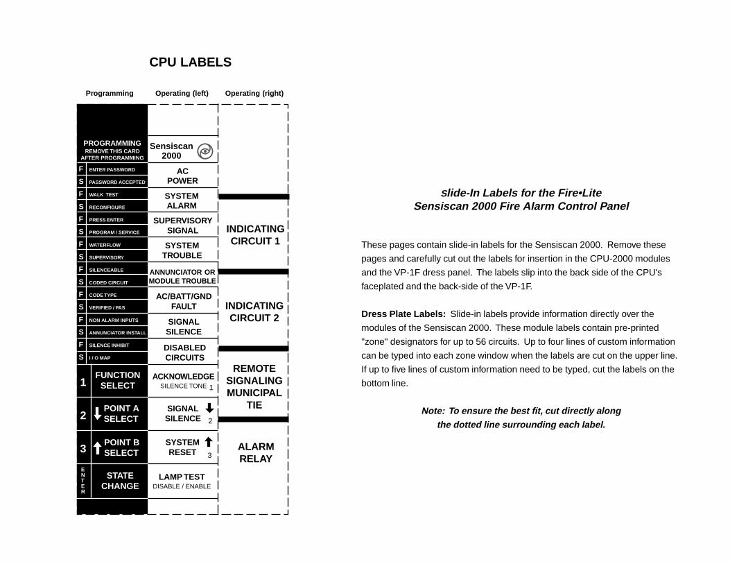
F
S
F
S
F
S
F
S
F
S
F
S
F
S
F
S
ENTER PASSWORD
PASSWORD ACCEPTED
WALK TEST
RECONFIGURE
PRESS ENTER
PROGRAM / SERVICE
WATERFLOW
SUPERVISORY
SILENCEABLE
CODED CIRCUIT
CODE TYPE
VERIFIED / PAS
NON ALARM INPUTS
ANNUNCIATOR INSTALL
SILENCE INHIBIT
I / O MAP
1
2
3
FUNCTIONSELECT
POINT ASELECT
POINT BSELECT
STATECHANGE
ENTER
INDICATINGCIRCUIT 1
INDICATINGCIRCUIT 2
REMOTESIGNALINGMUNICIPAL
TIE
ALARMRELAY
PROGRAMMINGREMOVE THIS CARD
AFTER PROGRAMMING
Sensiscan2000
ACPOWER
SYSTEMALARM
SUPERVISORYSIGNAL
SYSTEMTROUBLE
ANNUNCIATOR ORMODULE TROUBLE
AC/BATT/GNDFAULT
SIGNALSILENCE
DISABLEDCIRCUITS
ACKNOWLEDGESILENCE TONE
SIGNALSILENCE
SYSTEMRESET
LAMP TESTDISABLE / ENABLE
1
2
3
CPU LABELS
Programming Operating (left) Operating (right)
Slide-In Labels for the Fire•LiteSensiscan 2000 Fire Alarm Control Panel
These pages contain slide-in labels for the Sensiscan 2000. Remove these
pages and carefully cut out the labels for insertion in the CPU-2000 modules
and the VP-1F dress panel. The labels slip into the back side of the CPU's
faceplated and the back-side of the VP-1F.
Dress Plate Labels: Slide-in labels provide information directly over the
modules of the Sensiscan 2000. These module labels contain pre-printed
"zone" designators for up to 56 circuits. Up to four lines of custom information
can be typed into each zone window when the labels are cut on the upper line.
If up to five lines of custom information need to be typed, cut the labels on the
bottom line.
Note: To ensure the best fit, cut directly alongthe dotted line surrounding each label.